


Manual No.: M501-E376
Revision:
X-Ray High-Voltage Generator
ZUD-P40D/DS ZUD-L41D/DS
ZUD-L40D/DS ZUD-V40D/DS
ZUD-B40D/DS
INSTALLATION MANUAL
This manual is for professional service engineers. It bears no relation to the usual operation.
Manual No.: M501-E376
Revision:
NO TEXT

INDEX INSTALLATION
INDEX
1. Introduction............................................................................................................................. |
1-2 |
|
1.1 |
Introduction ....................................................................................................................... |
1-2 |
2. Technical Data ...................................................................................................................... |
2-2 |
|
2.1 |
Specifications and Installation Environment..................................................................... |
2-2 |
|
2.1.1 ZUD-P40D/DS ......................................................................................................... |
2-2 |
|
2.1.2 ZUD-L41D/DS , ZUD-L40D/DS ............................................................................... |
2-7 |
|
2.1.3 ZUD-V40D/DS ....................................................................................................... |
2-13 |
|
2.1.4 ZUD-B40D/DS ....................................................................................................... |
2-18 |
2.2 |
Internal Structure ............................................................................................................ |
2-24 |
|
2.2.1 ZUD-P40D/DS Cabinet.......................................................................................... |
2-24 |
|
2.2.2 ZUD-L41D/DS, ZUD-L40D/DS, ZUD-V40D/DS, ZUD-B40D/DS Cabinet ............. |
2-25 |
|
2.3.2 XSC-Z40RA/RB/RC Remote Operating Console.................................................. |
2-26 |
3. Installation and Connection.................................................................................................... |
3-2 |
|
3.1 |
Fixing the Cabinet............................................................................................................. |
3-2 |
|
3.1.1 ZUD-P40D/DS ......................................................................................................... |
3-2 |
|
3.1.2 ZUD-L40D/DS, ZUD-V40D/DS, ZUD-B40D/DS ...................................................... |
3-3 |
|
3.2 Setting of generator device of each type.................................................................... |
3-4 |
|
3.3 Setting of switch of each PCB setting jumper pin...................................................... |
3-5 |
|
3.3.1 Setting of switch of UD CONT-2005 PCB and jumper pin ...................................... |
3-5 |
|
3.3.2 Setting of TERMINAL-2005 PCB switch ................................................................. |
3-6 |
|
3.3.3 Setting EXT I/F-2005 PCB switch ........................................................................... |
3-7 |
|
3.3.4 Set to switch of DTC/SFC/OPT PCB and set to jumper pin.................................... |
3-7 |
|
3.3.5 Set to switch of Remote console XSC-Z40RA/RB/RC............................................ |
3-7 |
|
3.3.6 Set to switch of Local console ................................................................................. |
3-7 |
3.4 |
Connecting the Power Cable and Cables between Units................................................. |
3-8 |
|
3.4.1 ZUD-P40D/DS ......................................................................................................... |
3-9 |
|
3.4.2 ZUD-L41D/DS, ZUD-L40D/DS, ZUD-V40D/DS, ZUD-B40D/DS........................... |
3-11 |
3.5 |
Changing Connections According to the Power Supply Voltage.................................... |
3-13 |
|
3.5.1 ZUD-P40D/DS ....................................................................................................... |
3-14 |
|
3.5.2 ZUD-L41D/DS, ZUD-L40D/DS, ZUD-V40D/DS, ZUD-B40D/DS Three-phase |
|
|
400 V System........................................................................................................ |
3-15 |
|
3.5.3 ZUD-L41D/DS, ZUD-L40D/DS Single-phase 200 V System ................................ |
3-16 |
3.6 |
Starter Connections ........................................................................................................ |
3-19 |
3.7 |
X-ray High-voltage Cable Connection ............................................................................ |
3-19 |
3.8 |
Connections to External Equipment ............................................................................... |
3-21 |

INDEX INSTALLATION
|
3.8.1 R/F Table ZS-5D/5DS ........................................................................................... |
3-21 |
|
3.8.2 I.I. Unit, X-ray TV Unit, Digital Unit ........................................................................ |
3-24 |
|
3.8.3 Tube Select Signals............................................................................................... |
3-34 |
|
3.8.4 Door Open/Closed Confirmation Terminals .......................................................... |
3-34 |
3.9 |
Fixing the Cables ............................................................................................................ |
3-35 |
4. Checks and Adjustments........................................................................................................ |
4-2 |
|
4.1 |
Preparations ..................................................................................................................... |
4-3 |
|
4.1.1 Equipment Required for the Adjustments................................................................ |
4-3 |
|
4.1.2 Connecting the Adjustment PC ............................................................................... |
4-4 |
4.2 |
Checking the Supply Voltage Detection ........................................................................... |
4-5 |
4.3 |
Checking the Inverter Voltage Detection .......................................................................... |
4-6 |
4.4 |
Initial Settings ................................................................................................................... |
4-7 |
4.5 |
Checking Starter Operation ............................................................................................ |
4-15 |
|
4.5.1 Starter 4 CE/UL ..................................................................................................... |
4-15 |
|
4.5.2 Starter SA-42 ZUD ................................................................................................ |
4-15 |
4.6 |
Connecting the Tube Voltage/Tube Current Measuring Instruments............................. |
4-16 |
4.7 |
X-ray Tube Aging............................................................................................................ |
4-20 |
4.8 |
Adjusting the Radiography Tube Current ....................................................................... |
4-21 |
|
4.8.1 Preparations .......................................................................................................... |
4-21 |
|
4.8.2 Adjusting the Radiography Tube Current .............................................................. |
4-22 |
4.9 |
Adjusting the Fluoroscopy Tube Current........................................................................ |
4-23 |
|
4.9.1 Preparations .......................................................................................................... |
4-23 |
|
4.9.2 Adjusting the Continuous Fluoroscopy Tube Current ........................................... |
4-24 |
|
4.9.3 Pulse fluoroscopy tube current adjustment ........................................................... |
4-27 |
4.10 Checking and Adjusting the Tube Voltage ................................................................... |
4-29 |
|
4.11 Adjusting the Iris ........................................................................................................... |
4-31 |
|
4.12 Adjusting the I.I. Phototimer ......................................................................................... |
4-34 |
|
|
4.12.1 Preparations ........................................................................................................ |
4-34 |
|
4.12.2 Density Adjustment.............................................................................................. |
4-34 |
4.13 Adjusting the Direct Phototimer .................................................................................... |
4-39 |
|
|
4.13.1 Configuration ....................................................................................................... |
4-39 |
|
4.13.2 Installation............................................................................................................ |
4-40 |
|
4.13.3 Adjustment........................................................................................................... |
4-41 |
|
4.13.4 Density Adjustment.............................................................................................. |
4-43 |
4.14 Setting the Realtime Clock ........................................................................................... |
4-45 |
|
4.15 Setting the Intercom...................................................................................................... |
4-47 |
|
|
|
|
|
|
|

INDEX INSTALLATION
4.16 |
Console Settings........................................................................................................... |
4-49 |
4.17 |
APR Settings ................................................................................................................ |
4-50 |
4.17.1 Setting of remote console APR ........................................................................... |
4-50 |
|
4.17.2 Setting the APR of general radiography console ................................................ |
4-52 |
|
4.18 |
Adjusting the Memory Shot .......................................................................................... |
4-54 |
4.18.1 Preparations before Adjusting the Memory Shot ................................................ |
4-54 |
|
4.18.2 Setting the Fluoroscopy Conditions for Different Image Fields........................... |
4-54 |
|
4.18.3 Checking the Radiography Conditions ................................................................ |
4-56 |
|
4.18.4 Changing the Radiography Memory Shot Data................................................... |
4-58 |
|
4.18.5 Registering Memory Shot to APR ....................................................................... |
4-59 |
|
4.18.6 Checking the Backup (Direct Spot Filming)......................................................... |
4-59 |
|
4.18.7 Precautions when Changing the Direct Spot Filming Conditions........................ |
4-59 |
|
4.19 |
System information......................................................................................................... |
4-60 |
4.20 Communication Line Monitor........................................................................................... |
4-61 |
|
4.21 |
Error log......................................................................................................................... |
4-63 |
4.22 |
Setting of external output signal...................................................................................... |
4-64 |
4.23 |
Save setting data, and load. ............................................................................................ |
4-66 |
4.23.1 Procedure of saving and loading of setting data ................................................. |
4-66 |
|
4.23.2 Save setting data................................................................................................. |
4-67 |
|
4.23.3 Loading setting data ............................................................................................ |
4-68 |
|
4.24 |
Writing the present data to the EEPROM..................................................................... |
4-69 |
4.25 |
Initializing the EEPROM ............................................................................................... |
4-70 |
5. Options ................................................................................................................................... |
5-2 |
|
5.1 Installing the Optional Auto Transformer .......................................................................... |
5-2 |
|
5.1.1 Outline ..................................................................................................................... |
5-2 |
|
5.1.2 Configuration ........................................................................................................... |
5-2 |
|
5.1.3 Connections............................................................................................................. |
5-2 |
|
5.2 Installing the Starter 4 CE/UL (option).............................................................................. |
5-4 |
|
5.2.1 Outline ..................................................................................................................... |
5-4 |
|
5.2.2 Specifications .......................................................................................................... |
5-4 |
|
5.2.3 Configuration ........................................................................................................... |
5-5 |
|
5.2.4 Installation................................................................................................................ |
5-6 |
|
5.3 Installing Starter SA-42 ZUD (Option) .............................................................................. |
5-9 |
|
5.3.1 Outline ..................................................................................................................... |
5-9 |
|
5.3.2 Specifications .......................................................................................................... |
5-9 |
|
5.3.3 Configuration ......................................................................................................... |
5-10 |
|

INDEX INSTALLATION
5.3.4 Installation.............................................................................................................. |
5-11 |
5.3.5 Maintenance .......................................................................................................... |
5-14 |
5.3.6 Precautions............................................................................................................ |
5-16 |
5.4 Installing 2-tube Unit (Option)......................................................................................... |
5-17 |
5.4.1 Outline ................................................................................................................... |
5-17 |
5.4.2 Installation Procedure............................................................................................ |
5-20 |
5.4.3 GSC-2002S(Z) Installation and Wiring .................................................................. |
5-21 |
5.4.3.3 Connecting Cables to Control Cabinet ........................................................ |
5-24 |
5.4.3.4 GSC2002SZ Installation Method ................................................................. |
5-26 |
5.4.3.5 Assembling the Hand Switch Bracket Assembly ......................................... |
5-29 |
5.4.3.6 Wiring the GSC-2002S(Z) Control Console................................................. |
5-30 |
5.4.4 2 Connecting Two Tubes....................................................................................... |
5-31 |
5.4.5 Changing the Wiring Connections for One Tube................................................... |
5-37 |
5.4.6 Connecting the Attachments ................................................................................. |
5-38 |
5.5 Installation of connection unit ZUD (Option)...................................................................... |
5-45 |
5.5.1 Configuration ......................................................................................................... |
5-45 |
5.5.2 Connecting the cables ........................................................................................... |
5-46 |
5.5.3 Initial Setting .......................................................................................................... |
5-48 |
5.5.4 Operation Check.................................................................................................... |
5-49 |
5.5.5 Communications Specification .............................................................................. |
5-49 |
5.5.6 Message Formation............................................................................................... |
5-50 |
5.5.7 Physical Layer ....................................................................................................... |
5-50 |
5.5.8 Data Link Layer ..................................................................................................... |
5-51 |
5.5.9 Application Layer ................................................................................................... |
5-54 |
5.5.10 Communication Sequence .................................................................................. |
5-55 |
5.5.11 Details of Transmitted Text.................................................................................. |
5-55 |
5.6 Installation of Local Console (Option)................................................................................ |
5-66 |
5.6.1 Connection............................................................................................................. |
5-66 |
5.6.2 Setting.................................................................................................................... |
5-67 |
6 R/F Table System Option........................................................................................................ |
6-2 |
6.1 Installation control cabinet parts for Spot Film Device ..................................................... |
6-2 |
6.1.1 Outline ..................................................................................................................... |
6-2 |
6.1.2 Configuration ........................................................................................................... |
6-2 |
6.1.3 Parts Installation ...................................................................................................... |
6-3 |
6.1.4 Parts Wiring ............................................................................................................. |
6-5 |
6.2 Installation control cabinet parts for Oblique radiography unit. (Option) .......................... |
6-7 |
|
|
|
|

INDEX INSTALLATION
6.2.1 Outline ..................................................................................................................... |
6-7 |
6.2.2 Configuration ........................................................................................................... |
6-7 |
6.2.3 Parts Installation ...................................................................................................... |
6-9 |
6.2.4 Parts Wiring ........................................................................................................... |
6-11 |
6.3 Installation control cabinet parts for OPT Kit. (Option) ................................................... |
6-13 |
6.3.1 Outline ................................................................................................................... |
6-13 |
6.3.2 Configuration ......................................................................................................... |
6-13 |
6.3.2 Board OPT Installation and wiring......................................................................... |
6-14 |
6.4 Installation control cabinet parts for Image Speed Up unit. (Option).............................. |
6-16 |
6.4.1 Outline ................................................................................................................... |
6-16 |
6.4.2 Configuration ......................................................................................................... |
6-16 |
6.4.3 Parts Installation .................................................................................................... |
6-17 |
6.4.4 Parts Wiring ........................................................................................................... |
6-19 |

INDEX MAINTENANCE
INDEX
1. Detailed Adjustment Procedures......................................................................................... |
M1-2 |
|||||
1.1 |
Precautions.................................................................................................................... |
M1-2 |
||||
|
1.1.1 Introduction........................................................................................................... |
M1-2 |
||||
|
1.1.2 Equipment Required for the Adjustments............................................................. |
M1-2 |
||||
|
1.1.3 Precautions during Adjustments........................................................................... |
M1-3 |
||||
|
1.1.4 Connecting the Power Cable and Cables between Units .................................... |
M1-3 |
||||
|
1.1.5 Connecting the Adjustment PC ............................................................................ |
M1-4 |
||||
1.2 |
Turning ON Power and Checking Voltage..................................................................... |
M1-5 |
||||
|
1.2.1 Preparations Before Turning ON the Power......................................................... |
M1-5 |
||||
|
1.2.2 Turning ON Power................................................................................................ |
M1-6 |
||||
|
1.2.3 Voltage Check ...................................................................................................... |
M1-7 |
||||
|
1.2.4 Connecting the Connectors.................................................................................. |
M1-8 |
||||
|
1.2.5 Checking the Supply Voltage Detection ............................................................... |
M1-8 |
||||
1.3 |
Checking the Inverter Voltage Detection ..................................................................... |
M1-11 |
||||
|
1.3.1 ZUD-P40............................................................................................................. |
M1-11 |
||||
|
1.3.2 ZUD-L41/V40/B40 Series ................................................................................... |
M1-12 |
||||
1.4 |
Preparations for Test Operation (1)............................................................................. |
M1-15 |
||||
|
1.4.1 ZUD-P40............................................................................................................. |
M1-15 |
||||
|
1.4.2 ZUD-L41/L40/V40/B40 ....................................................................................... |
M1-15 |
||||
1.5 |
Checking the X-ray tube Filament Heating Circuit ...................................................... |
M1-16 |
||||
|
1.5.1 Checking the Pulsed Output for the Heating Setting.......................................... |
M1-16 |
||||
|
1.5.2 Checking the Power Circuit ................................................................................ |
M1-16 |
||||
|
1.5.3 Adjusting the Measured Tube Current System .................................................. |
M1-19 |
||||
1.6 |
Checking Main Inverter Operation............................................................................... |
M1-21 |
||||
|
1.6.1 ZUD-P40............................................................................................................. |
M1-21 |
||||
|
1.6.2 ZUD-L41/L40/V40/B40 ....................................................................................... |
M1-26 |
||||
1.7 |
Checking the VS/VN Output ........................................................................................ |
M1-29 |
||||
|
1.7.1 Adjusting |
|
and |
|
on KV ADJ-2002 PCB |
M1-29 |
|
kV+ |
kV- |
||||
1.8 |
Checking the Tube Voltage Feedback System ........................................................... |
M1-30 |
||||
|
1.8.1 Preparations ....................................................................................................... |
M1-30 |
||||
|
1.8.2 Adjustment.......................................................................................................... |
M1-30 |
||||
1.9 |
Checking the Feedback System Operation................................................................. |
M1-31 |
||||
1.10 Adjusting the Tube Voltage ....................................................................................... |
M1-33 |
|||||
1.11 Adjusting the Fluoroscopy Tube Voltage ...................................................................... |
M1-33 |
|||||
2. Replacing PCBs and Major Components............................................................................ |
M2-2 |
|||||
|
|
|
|
|
|
|
|
|
|
|
|
|
|

INDEX MAINTENANCE
2.1 |
Replacing PCBs and Major Components........................................................................... |
M2-2 |
2.2 |
Table of X-ray Tube Model Names................................................................................ |
M2-2 |
2.3 UD CONT-2005 Check Pin Arrangement Diagram ....................................................... |
M2-3 |
|
2.4 |
Fuse Lists....................................................................................................................... |
M2-5 |
2.5 |
Error Code Lists............................................................................................................. |
M2-6 |
|
2.4.1 Error Messages .................................................................................................... |
M2-6 |
2.6 |
High-voltage Transformer Oil Volumes ....................................................................... |
M2-10 |
3. Inspection and Maintenance ............................................................................................... |
M3-2 |
|
3.1 |
Periodic Replacement Parts .......................................................................................... |
M3-2 |

INDEX APPENDIX
INDEX
1. ZUD-HV Maintenance Tool Waveform Display Functions ................................................... |
A1-2 |
|
1.1 |
Introduction...................................................................................................................... |
A1-2 |
1.2 Equipment Required for the Adjustments..................................................................................................... |
A1-2 |
|
1.3 |
Starting the Waveform Display Functions .......................................................................... |
A1-2 |
2. UDCONT-2005 Firmware Update Procedure Manual ......................................................... |
A2-2 |
|
2.1 |
Introduction...................................................................................................................... |
A2-2 |
2.2 |
Equipment Required for Firmware Updating ....................................................................... |
A2-2 |
2.3 |
Firmware updating procedure............................................................................................ |
A2-2 |
2.4 |
Force updating procedure of UDCONT-2005 PCB........................................................... |
A2-11 |
2.5 |
Procedure of initialization of UDCONT-2005 built-in flash ROM....................................... |
A2-15 |
3. FLEXAVISION Remote / Local Console Firmware Update procedure ................................ |
A3-2 |
|
3.1 |
Introduction...................................................................................................................... |
A3-2 |
3.2 |
Equipment Required for Firmware updating........................................................................ |
A3-2 |
3.3 |
Firmware updating procedure............................................................................................ |
A3-3 |
3.4 |
Force Update Procedure of Remote/Local Console......................................................... |
A3-10 |
4. GSC-2002S(Z) for the 2-Tubes Option FLASH S/W Updating Procedure .......................... |
A4-2 |
|
4.1 |
Introduction...................................................................................................................... |
A4-2 |
4.2 |
Parts required and S/W.................................................................................................... |
A4-2 |
4.3 |
Preparation....................................................................................................................... |
A4-2 |
4.4 |
Update of S/W ................................................................................................................. |
A4-3 |
4.5 |
Confirmation Operation..................................................................................................... |
A4-7 |
|
|
|
|
|
|
I N S T A L L A T I O N
Chapter 1
1
Introduction
Chapter Contents
1.1 Introduction
1-1
M501-E376

I N S T A L L A T I O N
1.Introduction
1.1Introduction
This is the Installation Manual for the ZUD-P40D/DS, ZUD-L41D/DS, ZUD-L40D/DS, ZUD-V40D/DS, and ZUD-B40D/DS X-ray high-voltage generators for the FLEXAVISION X-ray TV system. These units incorporate a controller for the R/F table.
Install and adjust the apparatus in accordance with the steps described in this manual.
Before installing the equipment, check the items described in “2.1 Specifications and Installation Environment.” Then follow the procedures described in “3. Installation and Connection” and “4. Checks and Adjustments.”
The tube current is not adjusted at the factory.
Adjust the tube current during installation in accordance with the sections specified above.
1-2
M501-E376

I N S T A L L A T I O N 2.1 Specification and Installation Environment
Chapter 2
2
Technical Data
Chapter Contents
 2.1 Specifications and Installation Environment
 2.2 Internal Structure
2-1
M501-E376

I N S T A L L A T I O N 2. Technical Data
ZUD-P40D/DS
2.Technical Data
2.1Specifications and Installation Environment
2.1.1 ZUD-P40D/DS
Equipment Classifications
Type of protection against electric shocks: Class 1 equipment Degree of protection against electric shocks: Type B Waterproofing: Standard
Safe operation in air/flammable anesthetic gas or oxygen/nitrous oxide or flammable anesthetic gas atmosphere: Unsuitable
Operation mode: Continuous operation with intermittent load
Rated output (product of max. tube current that can flow in 0.1 sec and tube voltage at 100 kV tube voltage)
20 kW (100 kV, 200 mA) Short-time rating
125 kV 160 mA, 100 kV 200 mA, 80 kV 250 mA Long-time rating
125 kV 2.5 mA
Nominal max. tube voltage and maximum current at nominal max. tube voltage Short-time rating 125 kV 160 mA
Long-time rating 125 kV 2.5 mA
Max. tube current and maximum voltage at max. tube current Short-time rating 250 mA 80 kV
Long-time rating 2.5 mA 125 kV
Tube voltage and tube current combination at maximum electrical output Short-time rating 125 kV 160 mA, 100 kV 200 mA, 80 kV 250 mA Long-time rating 125 kV 2.5 mA
Nominal shortest radiation time (for AEC radiography) 3 ms
Radiography tube voltage 40-125kV
1 kV steps
2-2
M501-E376

I N S T A L L A T I O N 2.1 Specifications and Installation Environment
ZUD-P40D/DS
Radiography tube current 10-250 mA
Any 12 of the following positions that are permitted by the X-ray tube unit can be used: 10, 11, 12, 14, 16, 18, 20, 22, 25, 28, 32, 36, 40, 45, 50, 56, 63, 71, 80, 90, 100, 110, 125, 140, 160, 180, 200, 220, 250 mA
Radiography tube current time product 0.5-320 mAs
Set from the following 57 positions:
0.5, 0.56, 0.63, 0.71, 0.80, 0.90, 1.0, 1.1, 1.25, 1.4, 1.6, 1.8, 2.0, 2.2, 2.5, 2.8, 3.2, 3.6,4.0, 4.5, 5.0, 5.6, 6.3, 7.1, 8.0, 9.0, 10, 11, 12.5, 14, 16, 18, 20, 22, 25, 28, 32, 36, 40, 45, 50, 56, 63, 71, 80, 90, 100, 125, 140, 160, 180, 200, 220, 250, 280, 320 mAs
Radiography time 0.001-10 sec
Set from the following 81 positions. Do not set to a value less than 0.5 mAs or over 320 mAs.
1.0, 1.1, 1.25, 1.4, 1.6, 1.8, 2.0, 2.2, 2.5, 2.8, 3.2, 3.6, 4.0, 4.5, 5.0, 5.6, 6.3, 7.1, 8.0, 9.0, 10, 11, 12.5, 14, 16, 18, 20, 22, 25, 28, 32, 36, 40, 45, 50, 56, 63, 71, 80, 90 ms
0.10, 0.12, 0.14, 0.16, 0.18, 0.20, 0.22, 0.25, 0.28, 0.32, 0.36, 0.40, 0.45, 0.50, 0.56, 0.63, 0.80, 0.90, 1.0, 1.1, 1.25, 1.4, 1.6, 1.8, 2.0, 2.2, 2.5, 2.8, 3.2, 3.6, 4.0, 4.5,5.0, 5.6, 6.3, 7.1, 8.0, 9.0, 10 s
Fluoroscopy tube voltage 50-125 kV
1 kV steps Fluoroscopy tube current
0.3-2.5mA Fluoroscopy time
Continuous fluoroscopy time 10 minutes
Applicable Procedures
General radiography, fluoroscopic examinations, direct spot filming, DR radiography, vertical Bucky radiography, horizontal Bucky radiography
Radiography programs
User can create up to 12 radiography conditions per technique Number of connectable X-ray tube units
1 (2 with 2-tube option) Starter
Normal rotation
2-3
M501-E376

I N S T A L L A T I O N 2. Technical Data
ZUD-P40D/DS
Number of connectable AEC detectors
I.I. photocell type: 1
Direct phototimer photo sensor: 3 (SPT-XD only)
Options 2-tube option
Normal rotation starter (starter 4 CE/UL)
Power supply
Type and frequency AC, 50 or 60 Hz
Phases and nominal voltage Single-phase, 200/220/240 V
Permitted voltage range and power supply impedance under no-load status
200V-5%, 10% |
0.08 Ω |
220V±10% |
0.08 Ω |
240V±10% |
0.08 Ω |
Recommended distribution transformer capacity 30kVA
Length and Sectional Area of Lead-in Conductor vs Distribution Transformer Capacity
|
Length |
|
|
|
|
|
Sectional area of wire (mm2) |
|
|
|
|
|||||||
Transformer |
10 m |
|
20m |
30m |
40m |
|
50m |
|
60m |
70m |
80m |
90m |
100m |
|||||
max. |
|
|
|
|||||||||||||||
capacity |
|
|
|
|
|
|
|
|
|
|
|
|
|
|
|
|||
|
|
|
|
|
|
|
|
|
|
|
|
|
|
|
|
|
||
|
30 kVA |
22 |
|
22 |
22 |
38 |
|
38 |
|
38 |
38 |
60 |
60 |
60 |
||||
(single-phase) |
|
|
|
|||||||||||||||
|
|
|
|
|
|
|
|
|
|
|
|
|
|
|
|
|
||
|
Safety Devices |
|
|
|
|
|
|
|
|
|
|
|
|
|
|
|
||
|
|
|
|
|
|
|
|
|
|
|
|
|
|
|
|
|||
|
|
|
|
|
|
Safety Device |
|
|
|
|
|
Current rating of |
|
|
||||
|
|
|
|
|
|
|
|
|
|
|
|
|
|
recommended fuse or |
|
|
||
|
|
|
|
|
Type |
|
|
Capacity |
|
|
|
|
||||||
|
|
|
|
|
|
|
|
|
circuit breaker |
|
|
|||||||
|
Single-phase |
Knife switch or fuse or |
|
100 A min. |
|
|
|
60A |
|
|
|
|||||||
|
200/220/240V |
|
circuit breaker |
|
|
|
|
|
|
|
|
|||||||
|
|
|
|
|
|
|
|
|
|
|
|
|
|
|||||
If an earth leakage breaker is installed, use an inverter type that does not malfunction at high frequency current.
Earth
Grounding resistance 100 Ω max.
2-4
M501-E376

I N S T A L L A T I O N 2.1 Specifications and Installation Environment
ZUD-P40D/DS
Operating environment Temperature: 5°C to 35°C Humidity: 20% to 85%
Atmospheric pressure: 700 hPa to 1060 hPa No condensation
Provide a dedicated air-conditioning unit if the environmental conditions do not meet the conditions above.
Heat generated by equipment Control console: 30 kcal/h
Power cabinet: 500 kcal/h (120 kcal/h)
These heat generation values are values from an average operating state. The values may differ due to the operating state.
Values in parentheses ( ) indicate the heat generated by the X-ray tube unit. 1kW=860kcal/h
Power consumption
Standby: 500 VA
Short-time maximum rating: 45 kVA
Transport and storage environment Temperature: -10°C to 60°C Humidity: 10% to 95%
Atmospheric pressure: 700 hPa to 1060 hPa
The conditions above are for the transportation and storage of the equipment in its packaging.
Unit configuration Control cabinet Cables Accessories
(Operating console XSC-Z40RA/RB/RC Remote Operating Console)
2-5
M501-E376
I N S T A L L A T I O N 2. Technical Data
ZUD-P40D/DS
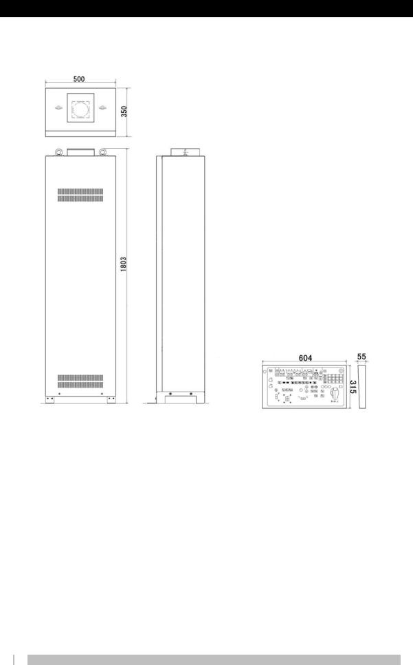
External dimensions and mass
Mass 170 kg |
Mass 7 kg |
2-6
M501-E376

I N S T A L L A T I O N 2.1 Specifications and Installation Environment
ZUD-L41D/DS , ZUD-L40D/DS
2.1.2 ZUD-L41D/DS , ZUD-L40D/DS
Equipment Classifications
Type of protection against electric shocks: Class 1 equipment Degree of protection against electric shocks: Type B Waterproofing: Standard
Safe operation in air/flammable anesthetic gas or oxygen/nitrous oxide or flammable anesthetic gas atmosphere: Unsuitable
Operation mode: Continuous operation with intermittent load
Rated output (product of max. tube current that can flow in 0.1secand tube voltage at 100 kV tube voltage)
Single-phase 200/220/240 V: 32 kW (100 kV, 320 mA)
3-phase 200/220/240 V: 50 kW (100 kV, 500 mA)
3-phase 380/400/415/440 V: 50 kW (100 kV, 500 mA)
Short-time rating
Single-phase 200/220/240 V: 150kV 200 mA, 125kV 250 mA, 100 kV 320 mA, 80 kV 400 mA 3-phase 200/220/240 V: 150 kV 320 mA, 125 kV 400 mA, 100 kV 500 mA, 80 kV 630 mA 3-phase 380/400/415/440 V: 150 kV 320 mA, 125 kV 400 mA, 100 kV 500 mA, 80 kV 630 mA
Long-time rating 125kV 4mA
Nominal max. tube voltage and maximum current at nominal max. tube voltage
Short-time rating |
Single-phase 200/220/240 V: |
150 kV, 200 mA |
|
3-phase 200/220/240 V: |
150 kV, 320 mA |
|
3-phase 380/400/415/440 V: |
150 kV, 320 mA |
Long-time rating |
125 kV 4 mA |
|
Max. tube current and maximum voltage at max. tube current |
||
Short-time rating |
Single-phase 200/220/240 V: |
400 mA 80 kV |
|
3-phase 200/220/240 V: |
630 mA 80 kV |
|
3-phase 380/400/415/440 V: |
630 mA 80 kV |
Long-time rating |
4 mA 125 kV |
|
Tube voltage and tube current combination at maximum electrical output |
||
Short-time rating |
Single-phase 200/220/240 V: |
100 kV 320 mA, 80 kV 400 mA |
|
3-phase 200/220/240 V: |
80 kV 630 mA |
|
3-phase 380/400/415/440 V: |
80 kV 630 mA |
Long-time rating |
125 kV 4 mA |
|
2-7
M501-E376

I N S T A L L A T I O N 2. Technical Data
ZUD-L41D/DS , ZUD-L40D/DS
Nominal shortest radiation time (for AEC radiography) 3 ms
Radiography tube voltage 40 kV to 150 kV
1 kV steps Radiography tube current
10 mA to 630 mA
Any 12 of the following positions that are permitted by the X-ray tube unit can be used: 10, 11, 12, 14, 16, 18, 20, 22, 25, 28, 32, 36, 40, 45, 50, 56, 63, 71, 80, 90, 100, 110, 125, 140, 160, 180, 200, 220, 250, 280, 320, 360, 400, 450, 500, 560, 630 mA
Radiography tube current time product 0.5-800 mAs
Set from the following 65 positions:
0.5, 0.56, 0.63, 0.71, 0.80, 0.90, 1.0, 1.1, 1.25, 1.4, 1.6, 1.8, 2.0, 2.2, 2.5, 2.8, 3.2, 3.6, 4.0, 4.5, 5.0, 5.6, 6.3, 7.1, 8.0, 9.0, 10, 11, 12.5, 14, 16, 18, 20, 22, 25, 28, 32, 36, 40, 45, 50, 56, 63, 71, 80, 90, 100, 125, 140, 160, 180, 200, 220, 250, 280, 320, 360, 400, 450, 500, 560, 630, 710, 800 mAs
Radiography time 0.001-10 sec
Set from the following 81 positions. Do not set to a value less than 0.5 mAs or over 800 mAs.
1.0, 1.1, 1.25, 1.4, 1.6, 1.8, 2.0, 2.2, 2.5, 2.8, 3.2, 3.6, 4.0, 4.5, 5.0, 5.6, 6.3, 7.1, 8.0, 9.0, 10, 11, 12.5, 14, 16, 18, 20, 22, 25, 28, 32, 36, 40, 45, 50, 56, 63, 71, 80, 90 ms
0.10, 0.12, 0.14, 0.16, 0.18, 0.20, 0.22, 0.25, 0.28, 0.32, 0.36, 0.40, 0.45, 0.50, 0.56, 0.63, 0.80, 0.90, 1.0, 1.1, 1.25, 1.4, 1.6, 1.8, 2.0, 2.2, 2.5, 2.8, 3.2, 3.6, 4.0, 4.5, 5.0, 5.6, 6.3, 7.1, 8.0, 9.0, 10 s
Fluoroscopy tube voltage 50 kV to 125 kV
1 kV steps Fluoroscopy tube current
0.3 mA to 4 mA Fluoroscopy time
Continuous fluoroscopy time 10 minutes
2-8
M501-E376
I N S T A L L A T I O N 2.1 Specifications and Installation Environment
ZUD-L41D/DS , ZUD-L40D/DS
Applicable Procedures
General radiography, fluoroscopic examinations, direct spot filming, DR radiography, vertical Bucky radiography, horizontal Bucky radiography
Radiography Programs
User can create up to 12 radiography conditions per technique Number of Connectable X-ray Tube Units
ZUD-L41D/DS: 1
ZUD-L40D/DS: 2 with 2-tube option Starter
High-speed rotation/normal rotation Number of connectable AEC detectors
I.I. photocell type: 1
Direct phototimer photo sensor: 3 (SPT-XD only)
Options 2-tube option
Auto transformer XAT-2 (3-phase 200/220/240 V required) High-speed starter (starter SA-42ZUD)
Normal rotation starter (STARTER 4 UL/CE) Direct phototimer option
Power Supply |
|
Type and frequency |
AC, 50 or 60 Hz |
Phases and nominal voltage |
Single-phase, 200/220/240 V |
|
3-phase 200/220/240 V |
|
3-phase 380/400/415/440 V |
Permitted voltage range and power supply impedance under no-load status
Single-phase 200/220/240 V |
200V-5%,+10% |
0.08 Ω |
|
220V±10% |
0.08 Ω |
|
240V±10% |
0.08 Ω |
3-phase 200/220/240 V |
200V-5%,+10% |
0.087 Ω |
|
220V±10% |
0.087 Ω |
|
240V±10% |
0.087 Ω |
2-9
M501-E376

I N S T A L L A T I O N 2. Technical Data
ZUD-L41D/DS , ZUD-L40D/DS |
|
|
3-phase 380/400/415/440 V |
380V±10% |
0.16 Ω |
|
400V±10% |
0.17 Ω |
|
415V±10% |
0.19 Ω |
|
440V±10% |
0.21 Ω |
Recommended distribution transformer capacity Single-phase 200/220/240 V: 30 kVA 3-phase 200/220/240 V: 50 kVA 3-phase 380/400/415/440 V: 50 kVA
Length and Sectional Area of Lead-in Conductor vs Distribution Transformer Capacity |
|
||||||||||||||||
|
|
|
|
|
|
|
|
|
|
|
|
|
|
|
|
||
Power cable |
Distribution |
|
|
|
|
Sectional area of wire (mm2) (Cu) |
|
|
|||||||||
|
transformer |
10m |
|
20m |
30m |
40m |
|
50m |
|
60m |
70m |
80m |
90m |
100m |
|||
|
capacity |
|
|
|
|||||||||||||
|
max. |
max. |
max. |
max. |
max. |
max. |
max. |
max. |
max. |
max. |
|||||||
|
kVA |
||||||||||||||||
|
|
|
|
|
|
|
|
|
|
|
|
|
|
|
|
|
|
Single-phase, |
30 |
14 |
|
22 |
38 |
60 |
|
60 |
|
100 |
100 |
100 |
100 |
100 |
|||
200 V |
|
|
|
||||||||||||||
|
|
|
|
|
|
|
|
|
|
|
|
|
|
|
|
|
|
3-phase, 400 V |
50 |
5.5 |
|
5.5 |
5.5 |
5.5 |
|
8 |
|
|
8 |
8 |
|
14 |
14 |
14 |
|
3-phase, 200 V |
50 |
8 |
|
14 |
14 |
22 |
|
38 |
|
38 |
38 |
|
60 |
60 |
60 |
||
Safety Devices |
|
|
|
|
|
|
|
|
|
|
|
|
|
|
|
|
|
|
|
|
|
|
|
|
|
|
|
|
|
|
|
|
|
||
|
|
|
|
|
|
Safety Device |
|
|
|
|
Current rating of |
||||||
|
|
|
|
|
|
|
|
|
|
recommended fuse |
|||||||
|
|
|
|
|
|
|
|
|
|
|
|
|
|
|
|||
|
|
|
|
|
|
Type |
|
|
|
|
|
Capacity |
|
or circuit breaker |
|||
Single-phase |
|
|
|
Knife switch or fuse or |
|
|
100 A min. |
|
|
100A |
|
||||||
200/220/240 V |
|
|
|
|
circuit breaker |
|
|
|
|
|
|||||||
|
|
|
|
|
|
|
|
|
|
|
|
|
|||||
3-phase |
|
|
|
Knife switch or fuse or |
|
|
100 A min. |
|
|
100A |
|
||||||
200/220/240 V |
|
|
|
|
circuit breaker |
|
|
|
|
|
|||||||
|
|
|
|
|
|
|
|
|
|
|
|
|
|||||
3-phase |
|
|
|
|
Circuit breaker |
|
|
- |
|
|
|
50A |
|
||||
380/400/415/440V |
|
|
|
|
|
|
|
|
|
||||||||
|
|
|
|
|
|
|
|
|
|
|
|
|
|
|
|
||
If an earth leakage breaker is installed, use an inverter type that does not malfunction at high frequency current.
Earth
Single-phase, 200/220/240 V: Grounding resistance 100 Ω max. 3-phase, 200/220/240 V: Grounding resistance 100 Ω max. 3-phase, 380/400/415/440 V: Grounding resistance 10 Ω max.
2-10
M501-E376

I N S T A L L A T I O N
|
2.1 Specifications and Installation Environment |
|
ZUD-L41D/DS , ZUD-L40D/DS |
Operating environment |
|
Temperature: |
5°C to 35°C |
Humidity: |
20% to 85% |
Atmospheric pressure: |
700 hPa to 1060 hPa |
No condensation |
|
Provide a dedicated air-conditioning unit if the environmental conditions do not meet the conditions above.
Heat generated by equipment Control console: 30 kcal/h
Power cabinet: 600 kcal/h (170 kcal/h)
These heat generation values are values from an average operating state. The values may differ due to the operating state.
Values in parentheses ( ) indicate the heat generated by the X-ray tube unit. 1 kW = 860 kcal/h
Power consumption |
|
|
Standby: 500 VA |
|
|
Short-time maximum rating: Single-phase 200/220/240 V: |
60 kVA |
|
|
3-phase 200/220/240 V: |
80 kVA |
|
3-phase 380/400/415/440 V: |
80 kVA |
Transport and storage environment |
|
|
Temperature: |
-10°C to 60°C |
|
Humidity: |
10% to 95% |
|
Atmospheric pressure: |
700 hPa to 1060 hPa |
|
The conditions above are for the transportation and storage of the equipment in its packaging.
Unit configuration Control cabinet Cables Accessories
(Operating console XSC-Z40RA/RB/RC Remote Operating Console)
2-11
M501-E376

I N S T A L L A T I O N 2. Technical Data
ZUD-L41D/DS , ZUD-L40D/DS
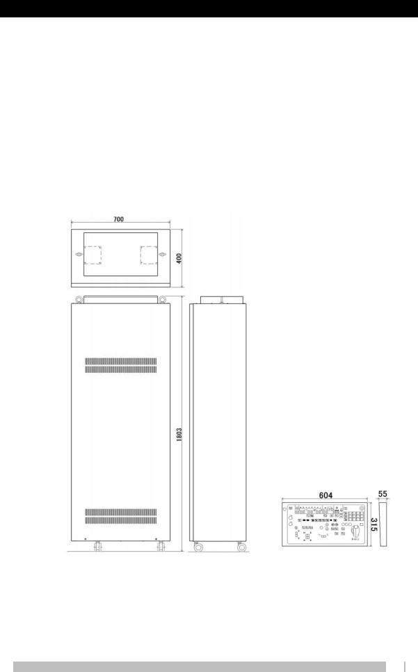
External dimensions and weight
Mass 270 kg |
Mass 7 kg |
2-12
M501-E376

I N S T A L L A T I O N 2.1 Specifications and Installation Environment
ZUD-V40D/DS
2.1.3 ZUD-V40D/DS
Equipment Classifications
Type of protection against electric shocks: Class 1 equipment Degree of protection against electric shocks: Type B Waterproofing: Standard
Safe operation in air/flammable anesthetic gas or oxygen/nitrous oxide or flammable anesthetic gas atmosphere: Unsuitable
Operation mode: Continuous operation with intermittent load
Rated output (product of max. tube current that can flow in 0.1 sec and tube voltage at 100 kV tube voltage)
65kW(100kV, 650mA)
Short-time rating
150kV 400mA, 125kV 500mA, 100kV 650mA, 80kV 800mA Long-time rating
125kV 4mA
Nominal max. tube voltage and maximum current at nominal max. tube voltage Short-time rating 150 kV 400 mA
Long-time rating 125 kV 4 mA
Max. tube current and maximum voltage at max. tube current Short-time rating 800 mA 80 kV
Long-time rating 4 mA 125 kV
Tube voltage and tube current combination at maximum electrical output Short-time rating 100 kV 650 mA
Long-time rating 125 kV 4 mA
Nominal shortest radiation time (for AEC radiography) 3 ms
Radiography tube voltage 40 kV to 150 kV
1 kV steps
2-13
M501-E376

I N S T A L L A T I O N 2. Technical Data
ZUD-V40D/DS
Radiography tube current 10 mA to 800 mA
Any 12 of the following positions that are permitted by the X-ray tube unit can be used: 10, 11, 12, 14, 16, 18, 20, 22, 25, 28, 32, 36, 40, 45, 50, 56, 63, 71, 80, 90, 100, 110, 125, 140, 160, 180, 200, 220, 250, 280, 320, 360, 400, 450, 500, 560, 630, 710, 800 mA
Radiography tube current time product 0.5 mAs to 800 mAs
Set from the following 65 positions:
0.5, 0.56, 0.63, 0.71, 0.80, 0.90, 1.0, 1.1, 1.25, 1.4, 1.6, 1.8, 2.0, 2.2, 2.5, 2.8, 3.2, 3.6, 4.0, 4.5, 5.0, 5.6, 6.3, 7.1, 8.0, 9.0, 10, 11, 12.5, 14, 16, 18, 20, 22, 25, 28, 32, 36, 40, 45, 50, 56, 63, 71, 80, 90, 100, 125, 140, 160, 180, 200, 220, 250, 280, 320, 360, 400, 450, 500, 560, 630, 710, 800 mAs
Radiography time 0.001 sec to 10 s
Set from the following 81 positions. Do not set to a value less than 0.5 mAs or over 800 mAs.
1.0, 1.1, 1.25, 1.4, 1.6, 1.8, 2.0, 2.2, 2.5, 2.8, 3.2, 3.6, 4.0, 4.5, 5.0, 5.6, 6.3, 7.1, 8.0, 9.0, 10, 11, 12.5, 14, 16, 18, 20, 22, 25, 28, 32, 36, 40, 45, 50, 56, 63, 71, 80, 90ms
0.10, 0.12, 0.14, 0.16, 0.18, 0.20, 0.22, 0.25, 0.28, 0.32, 0.36, 0.40, 0.45, 0.50, 0.56, 0.63, 0.80, 0.90, 1.0, 1.1, 1.25, 1.4, 1.6, 1.8, 2.0, 2.2, 2.5, 2.8, 3.2, 3.6, 4.0, 4.5, 5.0, 5.6, 6.3, 7.1, 8.0, 9.0, 10 s
Fluoroscopy tube voltage 50 kV to 125 kV
1 kV steps Fluoroscopy tube current
0.3 mA to 4 mA Fluoroscopy time
Continuous fluoroscopy time 10 minutes
Applicable Procedures
General radiography, fluoroscopic examinations, direct spot filming, DR radiography, vertical Bucky radiography, horizontal Bucky radiography
Radiography Programs
User can create up to 12 radiography conditions per technique Number of Connectable X-ray Tube Units
2
2-14
M501-E376

I N S T A L L A T I O N 2.1 Specifications and Installation Environment
ZUD-V40D/DS
Starter
High-speed rotation/normal rotation
Number of connectable AEC detectors
I.I. photocell type: 1
Direct phototimer photo sensor: 3 (SPT-XD only)
Options 2-tube option
Auto transformer (3-phase 200/220 V required) High-speed starter (starter SA-42ZUD) Normal rotation starter (starter 4 CE/UL) Direct phototimer option
Power Supply |
|
Type and frequency |
AC, 50 Hz or 60 Hz |
Phases and nominal voltage |
3- phase, 200/220/240 V |
|
3-phase 380/400/415/440 V |
Permitted voltage range and power supply impedance under negative load 3-phase 200/220/240 V 200V±10% 0.054 Ω
220V±10% 0.054 Ω 240V±10% 0.054 Ω
3-phase 380/400/415/440 V |
380V±10% |
0.10 Ω |
|
|
|
|
|
|
||||||
|
|
|
|
400V±10% |
0.11 Ω |
|
|
|
|
|
|
|||
|
|
|
|
415V±10% |
0.12 Ω |
|
|
|
|
|
|
|||
|
|
|
|
440V±10% |
0.13 Ω |
|
|
|
|
|
|
|||
Recommended distribution transformer capacity |
|
|
|
|
|
|
|
|||||||
3-phase 200/220/240 V: |
|
75 kVA |
|
|
|
|
|
|
|
|
||||
3-phase 380/400/415/440 V: |
75 kVA |
|
|
|
|
|
|
|
|
|||||
Length and Sectional Area of Lead-in Conductor vs Distribution Transformer Capacity |
|
|||||||||||||
|
|
|
|
|
|
|
|
|
|
|
|
|
|
|
|
Distribution |
|
|
|
|
|
|
|
|
2 |
) (Cu) |
|
|
|
Power cable |
transformer |
|
|
|
Sectional area of wire (mm |
|
|
|||||||
capacity |
|
10m |
20m |
30m |
|
40m |
50m |
60m |
70m |
80m |
90m |
100m |
||
|
kVA |
|
max. |
max. |
max. |
|
max. |
max. |
max. |
max. |
max. |
max. |
max. |
|
3-phase, 200 V |
75 |
|
14 |
22 |
38 |
|
38 |
60 |
60 |
60 |
100 |
100 |
100 |
|
3-phase, 400 V |
75 |
|
5.5 |
8 |
14 |
|
22 |
22 |
22 |
38 |
38 |
38 |
38 |
|
|
|
|
|
|
|
|
|
|
|
|
|
|
|
2-15 |
|
|
|
|
|
|
|
|
|
|
|
|
|
M501-E376 |
|

I N S T A L L A T I O N 2. Technical Data
ZUD-V40D/DS
Safety Devices
|
Safety Device |
|
Current rating of |
|
|
|
|
|
recommended fuse |
|
Type |
|
Capacity |
|
|
|
or circuit breaker |
||
3-phase |
Knife switch or fuse or |
|
100 A min. |
100 A |
200/220/240 V |
circuit breaker |
|
||
|
|
|
||
3-phase |
Circuit breaker |
|
- |
100 A |
380/400/415/440 V |
|
|||
|
|
|
|
|
If an earth leakage breaker is installed, use an inverter type that does not malfunction at high frequencies.
Earth
3-phase, 200/220/240 V: Grounding resistance 100 Ω max. 3-phase, 380/400/415/440 V: Grounding resistance 10 Ω max.
Operating environment |
|
Temperature: |
5 °C to 35 °C |
Humidity: |
20% to 85% |
Atmospheric pressure: |
700 hPa to 1060 hPa |
No condensation |
|
Provide a dedicated air-conditioning unit if the environmental conditions do not meet the conditions above.
Heat generated by equipment
Control console: |
30 kcal/h |
Power cabinet: |
680 kcal/h (220 kcal/h) |
These heat generation values are values from an average operating state. The values may differ due to the operating state.
Values in parentheses ( ) indicate the heat generated by the X-ray tube unit. 1 kW = 860 kcal/h
Power consumption
Standby: 500 VA
Short-time maximum rating: 120 kVA
Transport and storage environment
Temperature: |
-10 °C to 60 °C |
Humidity: |
10% to 95% |
Atmospheric pressure: |
700 hPa to 1060 hPa |
The conditions above are for the transportation and storage of the equipment in its
2-16
M501-E376
I N S T A L L A T I O N 2.1 Specifications and Installation Environment
ZUD-V40D/DS
packaging.
Unit configuration Control cabinet Cables Accessories
(Operating console: XSC-Z40RA/RB/RC Remote Operating Console)
External dimensions and weight
Mass 270 kg |
Mass 7 kg |
2-17
M501-E376

I N S T A L L A T I O N 2. Technical Data
ZUD-B40D/DS
2.1.4 ZUD-B40D/DS
Equipment Classifications
Type of protection against electric shocks: Class 1 equipment Degree of protection against electric shocks: Type B Waterproofing: Standard
Safe operation in air/flammable anesthetic gas or oxygen/nitrous oxide or flammable anesthetic gas atmosphere: Unsuitable
Operation mode: Continuous operation with intermittent load
Rated output (product of max. tube current that can flow in 0.1 sec and tube voltage at 100 kV tube voltage)
80 kW (100 kV, 800 mA)
Short-time rating
150kV 500mA, 125kV 630mA, 100kV 800mA, 80kV 1000mA Long-time rating
125kV 4mA
Nominal max. tube voltage and maximum current at nominal max. tube voltage Short-time rating 150 kV 500 mA
Long-time rating 125 kV 4 mA
Max. tube current and maximum voltage at max. tube current Short-time rating 1000 mA 80 kV
Long-time rating 4 mA 125 kV
Tube voltage and tube current combination at maximum electrical output Short-time rating 100 kV 800 mA, 80 kV 1000 mA
Long-time rating 125 kV 4 mA
Nominal shortest radiation time (for AEC radiography) 3 ms
Radiography tube voltage 40 kV to 150 kV
1 kV steps Radiography tube current
2-18
M501-E376
 Loading...