


Manual No.: M503-E329
Revision: B
Mobile X-ray System
High Power Type(32kW)
INSTALLATION MANUAL
This manual is for professional service engineers. It bears no relation to the usual operation.

TABLE OF CONTENTS
Chapter 1. Introduction
|
1.1 |
...............................................................................Directions for using the unit |
1-2 |
|
1.2 |
Document List...................................................................................................... |
1-3 |
Chapter 2. Outline
|
2.1 |
.....................................................................Conditions for Installation (using) |
2-2 |
|
2.2 |
Conditions for Transportation and Storage...................................................... |
2-3 |
|
2.3 |
Name of Each Part of the Unit ............................................................................ |
2-4 |
|
2.4 |
Name of Each Circuit Board and Layout of the Circuit Boards ...................... |
2-6 |
Chapter 3. Preprations for installation
|
3.1 |
...........................................................................Tools Required for Installation |
3-2 |
|
3.2 |
Unpacking............................................................................................................. |
3-3 |
|
3.3 |
Discharging the Internal Capacitor.................................................................... |
3-6 |
|
3.3 |
How to Open/Close the Covers .......................................................................... |
3-8 |
Chapter 4. Installation
|
4.1 |
.......................................................................................Installation Procedures |
4-2 |
|
4.2 |
Check Safety function ......................................................................................... |
4-5 |
|
4.3 |
Changing According to the Power Supply........................................................ |
4-6 |
|
4.4 |
Checking Performance of Each Part ................................................................. |
4-7 |
|
4.5 |
Installing the arm cover ...................................................................................... |
4-12 |
|
4.6 |
Attaching the knob for locking collimator rotation.......................................... |
4-13 |
|
4.7 |
Attaching screw caps.......................................................................................... |
4-14 |
|
4.8 |
Installing the apron hanger................................................................................. |
4-15 |
|
4.9 |
Reset of all parts usage information ................................................................. |
4-15 |
|
4.10 Assembler Test .................................................................................................. |
4-15 |
|
|
4.11 Charging the Battery after installation ............................................................ |
4-16 |
|
Chapter 5. Installing the Options
|
5.1 |
..................................................................Installing Remote Controller Option |
5-2 |
|
|
5.2 |
Installing folding–type Protective Screen Option ............................................ |
5-6 |
|
|
5.3 |
Installing Dose Area Product Meter Option ...................................................... |
5-10 |
|
|
5.4 |
Installing Dose Area Product Meter Option for UL........................................... |
5-17 |
|
|
5.5 |
Installing the Dose Calculation Unit .................................................................. |
5-24 |
|
|
5.6 |
Installing the Distance Indicator ........................................................................ |
5-31 |
|
|
5.7 |
Keyless Entry ....................................................................................................... |
5-36 |
|
|
5.8 |
Adjusting the Height of the Driving Handle ...................................................... |
5-40 |
|
|
5.9 |
Illuminated Hand Switch ..................................................................................... |
5-46 |
|
|
5.10 |
Additional Hand Switch..................................................................................... |
5-48 |
|
|
5.11 |
Installing the Grid Case Option........................................................................ |
5-51 |
|
|
5.12 |
Installing the Large Cassette Box Option ....................................................... |
5-55 |
|
|
5.13 |
FPD Upgrade Kit ................................................................................................ |
5-58 |
|
|
5.14 |
Decoration label................................................................................................. |
5-59 |
|
Chapter 6. Specifications
|
6.1 |
.......................................................................................................Specifications |
6-2 |
|
6.2 |
Dimensional Drawing of the Unit ....................................................................... |
6-10 |
|
6.3 |
X-ray Reference Axis and Focal Spot Position................................................. |
6-11 |
|
6.4 |
Exposure Condition............................................................................................. |
6-12 |
Appendix A. DIP Switches and Jumpers Setting on Each Board
|
.....................................................................................................A.1 NEX-SH Board |
A-2 |
|
A.2 X-CONT2008 Board ............................................................................................. |
A-4 |
|
A.3 INVERTER UNIT Board ....................................................................................... |
A-4 |
|
A.4 MU DRIVER 07 Board.......................................................................................... |
A-5 |
Appendix B. Adjustment Mode
|
....................................................................B.1 How to Get Into Adjustment Mode |
B-3 |
||
|
B.2 |
Initialization of NEX-SH Board........................................................................... |
B-6 |
|
|
B.3 |
Adjustment Mode List......................................................................................... |
B-7 |
|
|
B.4 |
Adjustment of Tube Current .............................................................................. |
B-9 |
|
|
B.5 |
Adjustment of the Handle................................................................................... |
B-16 |
|
|
B.6 |
Adjustment of the Battery Voltage Detection Circuit ...................................... |
B-18 |
|
|
B.7 |
Setting Date and Time ........................................................................................ |
B-20 |
|
|
B.8 |
Display and Reset of Error Log ......................................................................... |
B-22 |
|
|
B.9 |
Displaying Running Speed................................................................................. |
B-23 |
|
|
B.10 |
Battery Voltage Drop Check Mode .................................................................. |
B-25 |
|
|
B.11 |
Battery code setting mode............................................................................... |
B-27 |
|
|
B.12 Dose area product meter adjustment mode................................................... |
B-35 |
||
|
B.13 |
Dose calculation adjustment mode................................................................. |
B-43 |
|
|
B.14 |
Battery usage setting mode............................................................................. |
B-53 |
|
|
B.15 |
CPU board battery usage information setting mode ................................ |
B-55 |
|
|
B.16 |
Emergency brake release battery usage information setting mode............ |
B-57 |
|
|
B.17 |
X-ray tube unit usage information setting mode ........................................... |
B-59 |
|
|
B.18 |
Motor usage information setting mode .......................................................... |
B-61 |
|
|
B.19 |
Usage information collective setting mode.................................................... |
B-63 |
|
Appendix C. Adjusting Methods
|
C.1 |
..........................................................................................................Preparation |
C-2 |
|
C.2 |
Adjusting the battery-voltage detection circuit ............................................... |
C-3 |
|
C.3 Adjusting MUX CHARGE 32K board ................................................................. |
C-4 |
|
|
C.4 |
Adjusting mAs circuit of X-CONT2008 board................................................... |
C-6 |
|
C.5 |
Adjusting inverter control circuit of X-CONT2008 board................................ |
C-7 |
|
C.6 |
Operation Check of Capacitor Charging .......................................................... |
C-10 |
|
C.7 |
Checking the X-ray exposure............................................................................. |
C-12 |
|
C.8 |
Checking battery charging................................................................................. |
C-16 |
|
C.9 |
Volume control of a buzzer ................................................................................ |
C-18 |
|
C.10 Finish.................................................................................................................. |
C-19 |
|
Appendix D. Error Message List
|
..............................................................................................D.1 Error Message List |
D-2 |
Appendix E. Maintenance and Inspection
|
E.1 |
.........................................................................................Expendable Parts List |
E-2 |
|
|
E.2 |
Batteries Replacement........................................................................................ |
E-4 |
|
|
E.3 |
Replacement of the Motor .................................................................................. |
E-9 |
|
|
E.4 CPU Backup Battery Replacement.................................................................... |
E-14 |
||
|
E.5 |
Collimator lamp Replacement............................................................................ |
E-15 |
|
|
E.6 |
Maintenance of rotary X-ray tube section......................................................... |
E-17 |
|
|
E.7 |
Centering the Collimator and X-Ray Focus ...................................................... |
E-22 |
|
|
E.8 |
Adjustment of Collimator lamp voltage ............................................................ |
E-26 |
|
|
E.9 |
Cleaning and disinfections................................................................................. |
E-28 |
|
|
E.10 |
Replacing the Emergency Brake Release Battery ......................................... |
E-30 |
|
|
E.11 |
Version up of S/W for NEX-SH ......................................................................... |
E-32 |
|
|
E.12 |
PC Maintenance Function ................................................................................ |
E-38 |
|
Appendix F Operation of High-Voltage Cable
|
F.1 |
..................................................................Spare parts with high-voltage cable |
F-2 |
|
F.2 |
Installation procedure of the high-voltage generator side plug ..................... |
F-3 |
|
F.3 |
Installation procedure of the X-ray tube assembly side mini-plug ................ |
F-4 |

Chapter 1
Introduction
Before installing the unit, fully grasp the contents of this Installation Manual, and install it so that the system may deliver its full performance and functions.
Besides, thoroughly refer to the Operation Manual and Survice Manual of this unit.
Chapter Contents
1.1 Directions for using the unit
1.2 Document List
|
MobileArt Evolution High Power Type(32kW) Installation Manual |
|
1-1 |
|
|
|
Chapter 1 Introduction
1.1 Directions for using the unit
Directions about safety are described in this Section. Read this before installing the unit without fail.
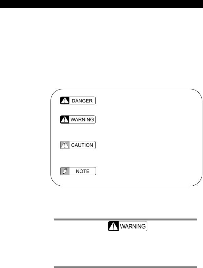
The meanings of the following precaution and prohibition terms used in the operation manual are defined as below:
States a direct danger that may cause death or serious injury if it is not avoided.
States an indirect or potential danger that may cause death or serious injury if it is not avoided.
States a danger that may cause slight or medium injury or may cause damage in equipment or fire if it is not avoided.
States the information which helps to use the system correctly.
In this system, large-capacity capacitors are connected to the battery. Even after turning OFF the key switch or the main breaker, electrical charge remains in the capacitor.
Be sure to discharge the capacitor when working on this system. (Refer to 3.3)
1-2 |
|
MobileArt Evolution High Power Type(32kW) Installation Manual |
|
|
|
|

Chapter 1 Introduction
1.2 Document List
If necessary, the following documents can be obtained. Contact the responsible service shop of Shimadzu Corporation.
Document |
Document Number |
MobileArt Evolution operation Manual |
M503-E027 |
|
|
MobileArt Evolution Installation Manual |
M503-E329 |
|
|
X-ray tube assembly Operation Manual |
M535-E219 |
|
|
MobileArt Evolution Parts List |
M503-4011 |
|
|
MobileArt Evolution Connection Diagram |
There is no document |
|
number. |
|
|
|
|
|
1-3 |
|
MobileArt Evolution High Power Type(32kW) Installation Manual |
|

Chapter 2
Outline
This chapter describes the outline and features of the equipment.
Read this chapter before installing the system.
Chapter Contents
 2.1 Conditions for Installation (using)
 2.2 Conditions for Transportation and Storage
 2.3 Name of Each Part of the Unit
 2.4 Name of Each Circuit Board and Layout of the Circuit Boards
MobileArt Evolution High Power Type(32kW) Installation Manual |
2-1 |
|

Chapter 2 Outline
2.1 Conditions for Installation (using)
 Use environment
Ambient temperature 10 to 40
Relative humidity 30% to 85% (no dew condensation)
Atmospheric pressure 700 hPa to 1060 hPa
The battery must be changed in the use environment.
Do not do it in the storage environment.
 Storage environment ( without a package for transport and storage )
Ambient temperature |
-10 to 40 |
Relative humidity |
30% to 85% (no dew condensation) |
Atmospheric pressure |
700 hPa to 1060 hPa |
 Power supply
AC power
|
System |
Single phase AC |
|
Frequency |
50/60 Hz |
|
Standard voltages |
100, 110, 120, 200, 220, 230, 240 V |
|
Voltage variation range |
±10% of standard voltages |
|
Supply capacity |
1kVA |
|
Supply Impedance |
100, 110, 120 V : 1.0Ωor less |
|
|
200, 220, 230, 240 V : 4.0Ωor less |
|
Earth |
|
|
|
|
|
Earth terminal |
Earth resistance of 100Ωor less |
Additional earth terminal Earth resistance of 100Ωor less
2-2 |
|
MobileArt Evolution High Power Type(32kW) Installation Manual |
|
Chapter 2 Outline
2.2 Conditions for Transportation and Storage
This condition is applied only at packed condition for transportation and storage.
 Transportation and Storage environment
Ambient temperature: |
-10 to 40 |
(The upper bound of the temperature is allowed up to 50 only for the period of less than one month.)
Relative humidity: |
10% to 95% |
Atmospheric pressure: |
700hPa to 1060hPa |
• When the unit is kept in storage for a long time until its installation, it is recommended to charge the battery within the following period in order to keep the performance of the battery:
Storage temperature 40 : Once every 2 months 30 : Once every 4 months 25 : Once every 6 months
• When the unit is kept in storage for a long time until its installation, it is recommended to travel the motor once every 3 month in order to keep the performance of the motor.
DO NOT CHARGE THE BATTERY WHEN PACKED.
Place the system in a well-ventilated area to charge the battery.
|
MobileArt Evolution High Power Type(32kW) Installation Manual |
|
2-3 |
|
|
|

Chapter 2 Outline
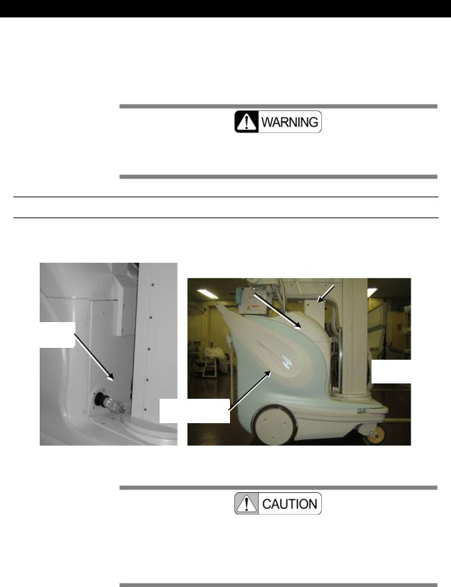
2.3 Name of Each Part of the Unit
Appearance
X-ray tube unit:
The X-ray tube with the collimator can turn around the X-ray focus. This makes a positioning and adjustment of the irradiation field and small movement of the unit.
Arm:
Holds the X-ray tube assembly. It can slide vertically along the column and the arm itself can stretch in the horizontal direction.
Column:
Holds the X-ray tube assembly and arm. It can turn itself
Grip bar(Driving handle):
The handle for the system driving.
Hand switch:
The switch to make X-ray exposures
2-4 |
|
MobileArt Evolution High Power Type(32kW) Installation Manual |
|

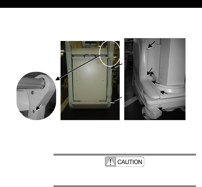
Chapter 2 Outline
Operating section
Emergency stop switch: |
Key switch: |
Use to stop the motor in an |
Turns the system on/off. |
emergency case. |
|
Battery indicator:
Indicate remaining charge of the battery.
X-ray control panel:
Refer to Operation Manual.
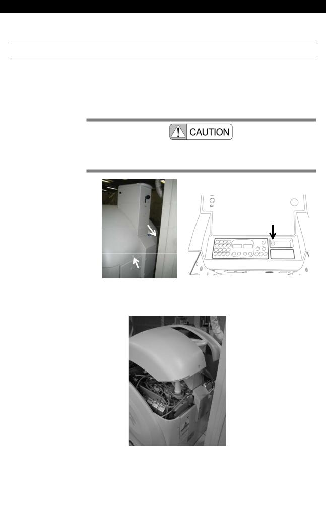
Power plug and main circuit breaker
|
Main circuit breaker: |
|
Turning off this breaker cut |
Power plug: |
off power for the whole unit. |
Use to charge the battery. |
The lid can be opened by |
|
pressing and releasing it. |
Obstruction detector:
Stop the unit in the event of a collision
|
MobileArt Evolution High Power Type(32kW) Installation Manual |
|
2-5 |
|
|
|

Chapter 2 Outline
2.4 Name of Each Circuit Board and Layout of the Circuit Boards
Right side of the unit
Discharge Switch
MUX CAPACITOR
BOARD
Xcont-2008
BOARD
NEXSH
BOARD
Bus Extender |
|
Breaker NFB1 |
Under side is ON
Left side of the unit
MUX |
|
Power 32K |
|
BOARD |
Inverter Unit |
|
|
|
32K |
|
BOARD |
BOARD
Charge 04B
MUX
MUX-LC1BF
BOARD
MUX
Charge 32K
BOARD
2-6 |
|
MobileArt Evolution High Power Type(32kW) Installation Manual |
|
Chapter 2 Outline
Lower part of the unit
MU DRIVER-07
BOARD
|
MobileArt Evolution High Power Type(32kW) Installation Manual |
|
2-7 |
|
|
|

Chapter 3
Preparations for installation
Before installing the unit, thoroughly read this Chapter and make necessary preparations.
Chapter Contents
 3.1 Tools Required for Installation
 3.2 Unpacking
 3.3 Discharging the Internal Capacitor
 3.4 How to Open/Close the Covers
|
MobileArt Evolution High Power Type(32kW) Installation Manual |
|
3-1 |
|
|
|

Chapter 3 Preparations for installation
3.1 Tools Required for Installation
When installing the unit, prepare the following tools:
•Screw drivers and Philips screw drivers
•Hexagonal bar L-type spanners: No. 2.5 10
•Nipper
•Pliers
•Tester
•Insulok
•Grease
•Cutter
•Waste cloth
•Alligator clip
•Alcohol for cleaning
•Oscilloscope
•Hexagonal bolt M8 x 16: (Only for exchanging X-ray tube assembly)
•Pliers for FU Lock nut AW04: (Only for exchanging X-ray tube assembly)
•Spring gauge: (Only for adjusting X-ray tube assembly or adjustment of handle)
3-2 |
|
MobileArt Evolution High Power Type(32kW) Installation Manual |
|
|
|

3.2 Unpacking
3.2 Unpacking
Make sure that the following items are contained:
|
|
|
|
|
|
|
Quantity |
Description |
|
MobileArt Evolution type 32kW |
1 |
|
|
||||||
Components |
|
Arm cover |
1 |
|
|
||||
|
|
|
Spare |
|
Fuse 313.500 |
1 |
|
|
|
|
|
|
parts |
|
Fuse 313001 |
1 |
|
|
|
|
|
|
|
|
|
Fuse 313002 |
1 |
|
|
|
|
|
|
|
|
Fuse 313005 |
1 |
|
|
|
|
|
|
|
|
Fuse 3136.25 |
1 |
|
|
|
|
|
|
|
|
Fuse 326010 |
1 |
|
|
|
|
|
|
|
|
Fuse 660CF-10UL |
1 |
|
|
|
|
|
|
|
|
Label, Input Voltage |
1 |
|
|
|
|
|
|
|
|
Cap |
5 |
White |
|
|
|
|
|
|
|
Cap |
2 |
Blue |
|
|
|
|
|
|
|
Release Switch Label |
2 |
|
|
|
|
|
|
|
|
SH_MUX200 S/W |
1 |
|
|
|
|
|
Operation Manual |
1 |
|
|
|||
|
|
|
Installation Manual |
1 |
|
|
|||
|
|
|
Parts List |
1 |
|
|
|||
|
|
|
|
|
|
|
|
||
|
Options |
|
|
Remote controller |
|
|
|
||
|
|
|
|
|
Protective screen |
|
|
|
|
|
|
|
|
|
Dose area product meter |
|
|
|
|
|
|
|
|
|
Dose calculation unit |
|
|
|
|
|
|
|
|
|
Distance indicator |
|
|
|
|
|
|
|
|
|
Keyless entry |
|
|
|
|
|
|
|
|
|
Changing the grip bar height |
|
|
|
|
|
|
|
|
|
Luminous hand switch |
|
|
|
|
|
|
|
|
|
Additional a hand switch |
|
|
|
|
|
|
|
|
|
Grid case |
|
|
|
|
|
|
|
|
|
Large cassette box |
|
|
|
|
|
MobileArt Evolution High Power Type(32kW) Installation Manual |
|
3-3 |
|
|
Chapter 3 Preparations for installation
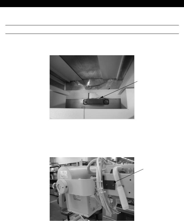
Remove Fixing bracket for device shipment
1. Remove the red plate fixing the column rotation-lock pin. Then, paste the attached sponge on the place, where the red plate was fixed.
Fixing plate
Fig.3- 1
2. Remove the column rotation-lock pin.
3. Remove both sides of the fixing bracket for Tube rotation-lock and the arm extension retaining at tip of arm.
Fixing bracket
Fig.3- 2
3-4 |
|
MobileArt Evolution High Power Type(32kW) Installation Manual |
|
|
|
3.2 Unpacking
4. Unscrew the weight fixing bolt. If it is hard to remove, loosen the bolt (a) at the arm fixing bracket shown in the following figure.
Arm fixing bracket
(a) |
|
|
(a) |
|
|
|
|
|
|
|
|
|
|
|
|
|
|
|
|
|
|
Weight fixing bolt |
||
|
|
|
|
|
Fig.3- 3
5. Finally remove the arm fixing bracket.
6. After unpacking, turn ON the main breaker and the switch (see Fig.3- 6), move to the place, where X-ray radiography is executable and there is a power outlet. The main breaker is at the front side of the system.
ON
ON OFF
OFF
Fig.3- 4 Key switch
Fig.3- 5 Main breaker
When the system is parked for long time, this might flat the wheels where contacts the floor. Runing the system, the wheels will be back the original shape gradually.
Use the fixing brackets for transportation when the system is transported by a track etc.
|
MobileArt Evolution High Power Type(32kW) Installation Manual |
|
3-5 |
|
|
Chapter 3 Preparations for installation
3.3 Discharging the Internal Capacitor
In this system, large-capacity capacitors are connected to the battery. Even after turning OFF the key switch or the main breaker, electrical charge remains in the capacitor.
Be sure to discharge the capacitor when working on this system.
1.
2.
3.
4.
Confirm that both the key switch and the main breaker are turned OFF.
Remove the right-side cover.
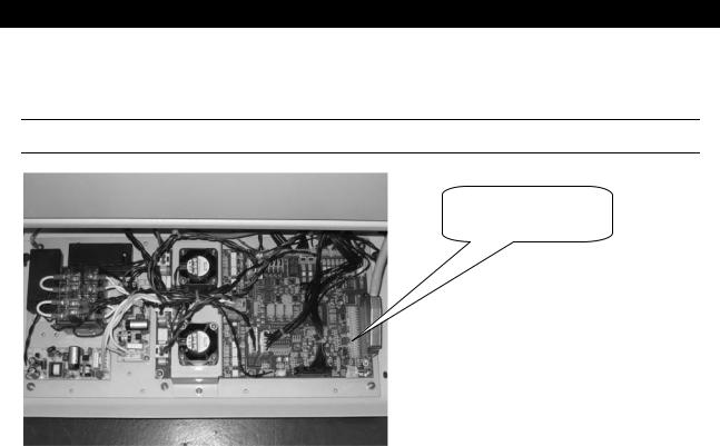
Confirm that the discharge switch is set to “NORMAL” (left side).
Disconnect the CN1/CN2 cable from the CN2 connector “NORMAL” on the MUX CAPACITOR board and connect it to the CN1 connector “DISCHARGE”. If electrical charge is remaining in the capacitor, the LED on the MUX CAPACITOR board will be lit.
Fig.3- 6
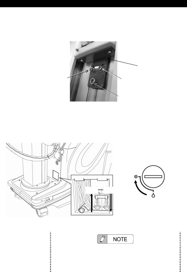
5. Set the discharge switch to “DISCHARGE” (right side). Discharge of the internal capacitor is started.
3-6 |
|
MobileArt Evolution High Power Type(32kW) Installation Manual |
|
|
|

3.3 Discharging the Internal Capacitor
Fig.3- 7
6. Five minutes or more will be required to reach the capacitor voltage to 1 V or less. Capacitor voltage can be checked by using check pins CP1-CP2 on the MUX CAPACITOR board.
7. After all work is finished, to return the system to normal operation status, confirm again that both the key switch and the main breaker are turned OFF, then set the discharge switch to “NORMAL” (left side), and reconnect the CN1/CN2 cable to the CN2 connector “NORMAL” on the MUX CAPACITOR board.
|
MobileArt Evolution High Power Type(32kW) Installation Manual |
|
3-7 |
|
|
Chapter 3 Preparations for installation
3.4 How to Open/Close the Covers
Be sure to turn off the main breaker. There is a danger of receiving electric shock.
Name and Layout of the Covers
|
|
|
|
|
Arm joint section |
|
|
Top cover |
|
|
|||
|
|
|||||
|
|
|
|
|
|
|
|
|
|
|
|
|
|
|
|
|
|
|
|
|
|
|
|
|
|
|
|
Front cover
 Cable cover
Side cover
Fig.3- 8 Name and layout of the covers
Do NOT pull the imaging unit's cable.
If the cable catches on something, do NOT pull on the imaging unit. Doing so can cause in cable damage, fire, electric shock, unit damage, or malfunction.
3-8 |
|
MobileArt Evolution High Power Type(32kW) Installation Manual |
|
|
|
3.4 How to Open/Close the Covers
1. Remove eight screws shown in Fig.3- 9.
Fig.3- 9 Points to screw on the side cover
2. Pull the side cover sideways to detach.
Be careful to remove the right side cover. The right side cover and the main unit are connected with the cable of the hand switch.
|
MobileArt Evolution High Power Type(32kW) Installation Manual |
|
3-9 |
|
|
Chapter 3 Preparations for installation
How to Open/Close the Top cover
1. Unscrew screws as shown in Fig.3- 10 (a).
2. Unscrew screws on the Top cover as shown in Fig.3- 10 (b).
3. Pull up the front part of the top cover (Fig.3- 11).
The top cover and the main unit are connected with the cables. Be careful to remove the top cover.
(a) |
(b) |
Fig.3- 10 Screw cramp positions of the top cover
Fig.3- 11 How to open/close the top cover.
3-10 |
|
MobileArt Evolution High Power Type(32kW) Installation Manual |
|
|
|
3.4 How to Open/Close the Covers
How to Open/Close the Front Cover
1. Unscrew screws as shown in Fig.3- 12 and remove the top cover to the side of the unit.
2. Slightly holding up the column under-cover, pull out forward and remove the cover.
Column under-cover
Fig.3- 12 Method of opening/closing the front cover
How to Open/Close the Front Rear Cover
3.
4.
Unscrew 2 screws as shown in Fig.3- 13 (a).
Unscrew 4 screws in the column under-cover as shown in Fig.3- 13 (b).
5. Remove the front rear-cover, slightly holding up the column under-cover, as shown in Fig.3- 13 (c).
(a) |
(b) |
(c) |
Fig.3- 13 Method of opening/closing the front rear-cover
|
MobileArt Evolution High Power Type(32kW) Installation Manual |
|
3-11 |
|
|
Chapter 3 Preparations for installation
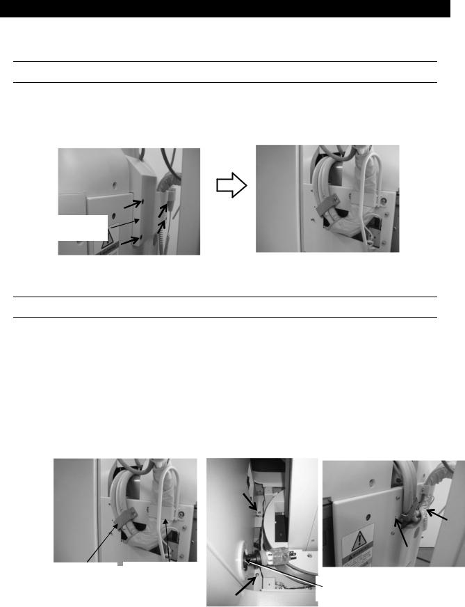
How to Open/Close the Cable Cover
1. Loose 4 hexagon socket head cap screws as shown in Fig.3- 14.
2. Pull the cable cover upward and remove it.
Cable Cover
Fig.3- 14 Screw cramp positions of the cable cover
How to Open/Close the Front Cover
1. Remove the front side cover and front rear cover.
2. Remove the cable cover.
3. Remove the cable guard and cable holder.
4. Remove the code guide.
5. Unscrew 4 screws as shown in Fig.3- 15 and remove the front cover.
Cable Holder |
Cable Guard |
Cord guide
Fig.3- 15 Screw cramp positions of the front cover
3-12 |
|
MobileArt Evolution High Power Type(32kW) Installation Manual |
|
|
|
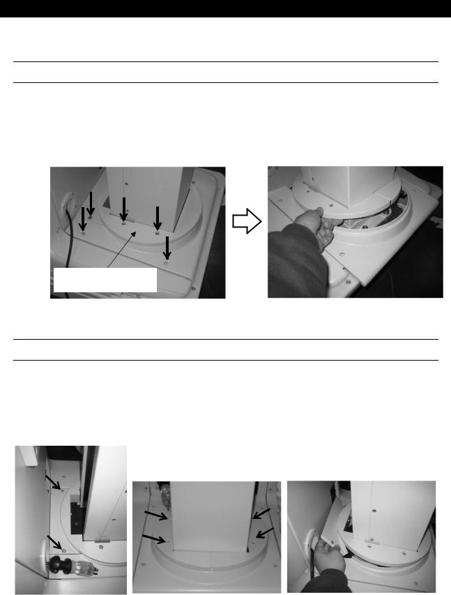
3.4 How to Open/Close the Covers
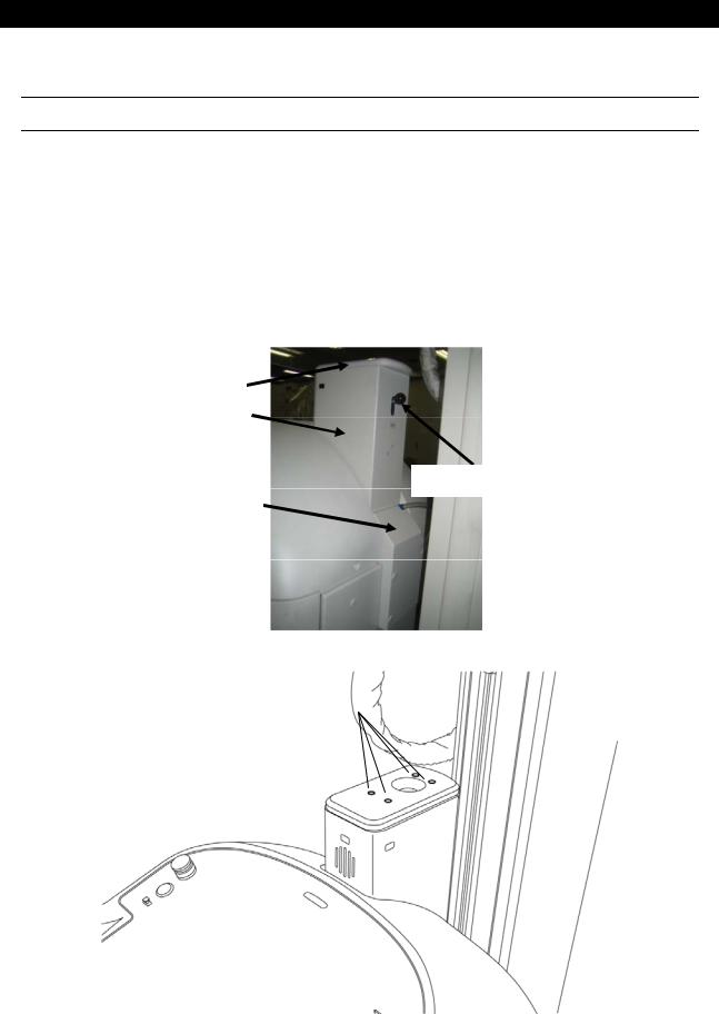
How to Open/Close the Arm Joint Section
1.
2.
Remove the upper cover and the cable cover.
Unscrew the hexagon socket head cap screws at 4 locations indicated in Fig.3- 17.
3. Remove the knob of the arm lock release lever by turning it counterclockwise.
4. Pull out the top plate and the main cover of the arm joint section.
Top plate
Main cover of arm joint section
Arm Lock release lever
Cable Cover
Fig.3- 16 Name of each part of the arm joint section
Hexagon socket head cap screw M4
Fig.3- 17 Screw cramp positions of Top plate
|
MobileArt Evolution High Power Type(32kW) Installation Manual |
|
3-13 |
|
|

Chapter 4
Installation
Install the system properly in the procedures described in this Chapter.
Chapter Contents
 4.1 Installation Procedures
 4.2 Check Safety function
 4.3 Changing According to the Power Supply
 4.4 Checking Performance of Each Part
 4.5 Installing the arm cover
 4.6 Attaching the knob for locking collimator rotation
 4.7 Attaching screw caps
 4.8 Installing the apron hanger
 4.9 Reset of all parts usage information
 4.10 Assembler Test
 4.11 Charging the Battery after installation
In this system, large-capacity capacitors are connected to the battery. Even after turning OFF the key switch or the main breaker, electrical charge remains in the capacitor.
Be sure to discharge the capacitor when working on this system. (Refer to 3.3)
|
MobileArt Evolution High Power Type(32kW) Installation Manual |
|
4-1 |
|
|
|
Chapter 4 Installation
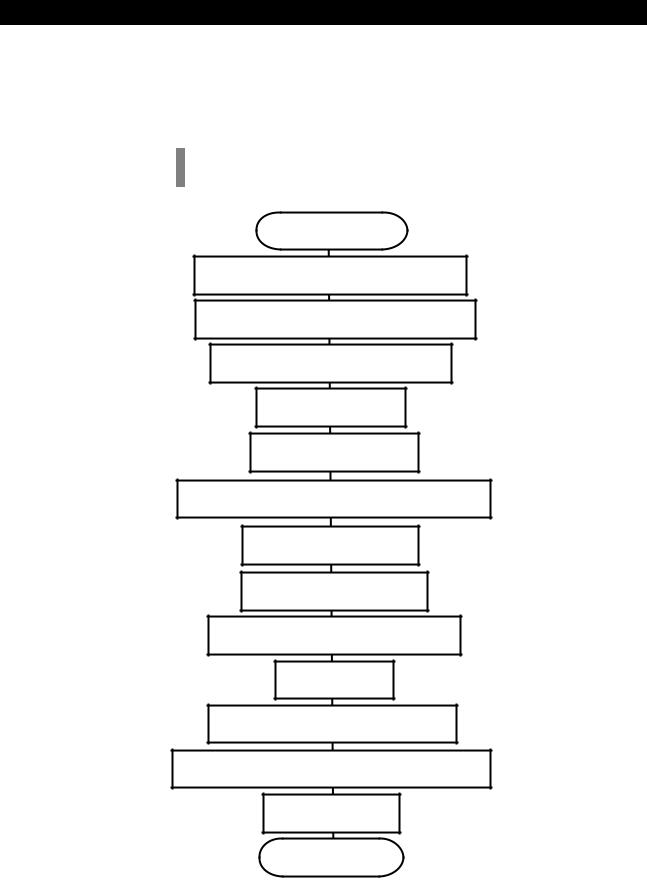
4.1 Installation Procedures
Install the system according to the flowchart below.Fill in the
Installation Performance Check Sheet in accordance with table 4-1.
Start
Check Safety function (Refer to 4.2)
Changing According to the Power Supply (Refer to4.3)
Checking Performance of Each Part
(Refer to 4.4)
Installing options (Refer to Chapter 5)
Installing the arm cover (Refer to4.5)
Attaching the knob for locking collimator rotation (Refer to 4.6)
Attaching screw caps (Refer to 4.7)
Installing the apron hanger (Refer to 4.8)
Reset of all parts usage information (Refer to4.9)
Assembler Test
(Refer to 4.10)
Charging the Battery after installation (Refer to 4.11)
Explanation of MobileArt Evolution operation to customer
Clinical application
End
4-2 |
|
MobileArt Evolution High Power Type(32kW) Installation Manual |
|
|
|
 Loading...