


Shimadzu UP4201Y, UP823X, UP623Y, UP823Y, UP822Y User Manual
...Top-loading Balance
UPX Series
UP223X, |
UP423X, |
UP623X, |
UP823X, |
UP1023X |
UP422X, |
UP822X |
|
|
|
UP2202X, |
UP4202X, |
UP6202X |
|
|
UP4201X, |
UP8201X |
|
|
|
UPY Series
UP223Y, |
UP423Y, |
UP623Y, |
UP823Y, |
UP1023Y |
UP422Y, |
UP822Y |
|
|
|
UP2202Y, |
UP4202Y, |
UP6202Y |
|
|
UP4201Y, |
UP8201Y |
|
|
|
Instruction Manual
Read the instruction manual thoroughly before you use the product. Keep this instruction manual for future reference.
UP0000x |
UP0000x |
3 |
|
|
3 |
S321-78282
Aug. 2019
|
Foreword |
|
1. |
Name and Function |
|
of Components |
||
2. |
Installation |
|
3. |
Basic Operation |
|
4. |
Menu Item Selection |
|
5. |
Built-in Clock Set-up |
|
6. |
Display Selection |
|
7. |
Calibration |
|
8. |
Environment |
|
9. |
Unit Display Set-up |
|
10. |
ProductivityEnhancing |
|
11. |
FunctionsApplication |
|
12. |
Connections and |
|
Communications with |
||
External Equipment |
||
13. |
Maintenance and |
|
Transportation |
||
14. |
Troubleshooting |
|
Appendices
No text

Foreword
Read the instruction manual thoroughly before using the product.
Thank you for purchasing the Shimadzu Top-loading Balance UP Series.
This instruction manual provides details on how to use the balance and on the accessories and options, etc., that are related to it. Read the manual thoroughly and make sure it is used in accordance with the details listed herein. The following instruction manual is also supplied with this product.
Simple Sheet: Operation Guide |
321-78282 |
Operation descriptions in a simple diagram format. |
Store the instruction manuals together with the product in an easily-accessible location.
The instruction manuals (PDF format) can also be downloaded from the Shimadzu website
(https://www.an.shimadzu.co.jp/balance/) Balances |
SEARCH |
|
Click |
Notices
•If the balance is to be operated by a different user or transferred to a different location, make sure the instruction manuals are also provided to the subsequent users.
•Contact the Shimadzu sales office or agency in the event of the instruction manuals were lost or mislaid.
•Safety precautions are listed in the instruction manual to ensure safe usage. Read the section on [Safety Precautions] thoroughly prior to using the balance.
•You are requested to complete the user registration procedure to ensure that your balance can be used without anxiety. This is required when making claims against the product warranty, and you are requested to complete either of the following two user registration procedures.
(1)Fill in the details on the rear of the [Product Warranty] card provided, and send it to us by facsimile.
(2)Access our website and will in the details accordingly.
(https://www.an.shimadzu.co.jp/balance/user/index.html)
Once you have completed the user registration procedures, you will be given precedence with regard to receiving information on product warranty and Shimadzu products and services. (You are also requested to fill in the questionnaire.)
 Notices
•The content of this manual is subject, without notice, to modifications for the sake of improvement.
•Every effort has been made to ensure that the content of this manual was correct at the time of creation. However, in the event that any mistakes or omissions are discovered, it may not be possible to correct them immediately.
•The copyright of this manual is owned by Shimadzu Corporation. Reproduction and duplication of whole or part of the content without permission of the company are strictly prohibited.
•Windows is the registered trademark of Microsoft Corporation of the U.S.A. in the United States and other countries. All other company names and product names that appear in this manual are trademarks or registered trademarks of the companies concerned. Note that ™ and ® indications are not used.
•UniBloc and Smart+ are the registered trademarks of Shimadzu Corporation in Japan.
•Shimadzu does not guarantee that the serial communication functions will operate without problem on all PCs. Shimadzu will not accept responsibility for any trouble that arises as a result of using this function. It is recommended that all important data and programs are backed up in advance.
©2019 Shimadzu Corporation. All rights reserved.
I

Foreword
Notation Conventions Used within the Instruction Manual
The instruction manual uses the following notation conventions in accordance with the degree of risk and damage to equipment.
Notation |
Description |
|
|
|
|
! Caution |
Indicates a potentially hazardous situation which, if not avoided, |
|
may result in minor to moderate injury or equipment damage. |
||
|
||
|
|
|
Note |
Provides additional information needed to properly use the |
|
balance. |
||
|
||
|
|
Descriptions of the other pictograms used within the instruction manual are listed below.
Pictogram |
Description |
Indicates an action that must NOT be performed
Prohibitions
Indicates an action that must be performed.
Instructions
The functions available for use and the selectable items differ in accordance with the model with the UP Series. Read the sections concerning the model in use.
|
|
|
Other conventions used in this manual include: |
|
|
|
|
|
|
1, 2, 3, … |
Indicates the step number in a procedure |
|||
[POWER] key |
Indicates the operation key on the balance. |
|||
|
|
|
|
|
|
|
|
Items displayed on the balance display are shown in [ ] brackets. |
|
[E-CAL ] etc... |
This also includes displayed items when selecting a menu item and is also used to identify |
|||
|
|
|
menu items. |
|
mass display |
Indicates that the balance is in the weighing mode and mass is displayed in one of the |
|||
weighing units. |
||||
|
|
|
||
Mass display |
Indicates that the balance display is in one of the mass units and that the value displayed will |
|||
change according to the load on the pan. |
||||
|
|
|
||
|
|
|
Indicates the menu item to be selected. |
|
|
1 |
|
||
|
|
In the number of the menu item on the Menu Map. See A-2 “Menu Map”. |
||
|
|
|
||
|
|
|
||
II
UP Series
The UP Series comprises of the Top-loading equilibrium balances mounted with aluminum UniBloc sensors. This instruction manual provides details on operating the UP Series models listed below. The functions available differ in accordance with the model, so check the product label located on the front or back of the balance and read the sections concerning the model in use.
About the model name
Example: UP223X
Model name
Capacity |
|
Minimum display |
|
22: |
220g |
1: 0.1 |
g |
42: |
420g |
2: 0.01 |
g |
62: |
620g |
3: 0.001 |
g |
82: |
820g |
|
|
102: 1020g 220: 2200 g 420: 4200 g
620: |
6200 g |
820: |
8200g |
 Series name
X: X Series (with built-in calibration weight)
Y: Y Series
UP Lineup
UPX Series |
UP223X |
|
|
|
UP423X |
|
|
|
UP623X |
Small pan type UP823X
UP1023X
UP422X
UP822X
UP2202X
UP4202X
Large pan type UP6202X
UP4201X
UP8201X
UPY Series |
UP223Y |
|
|
|
UP423Y |
|
|
|
UP623Y |
UP823Y
Small pan type UP1023Y
UP422Y
UP822Y
UP2202Y
UP4202Y
Large pan type UP6202Y
UP4201Y
UP8201Y
For information on the following points, please contact your Shimadzu Balance representative.
•Product warranty
•After service
III

Safety Precautions
Use
To be strictly observed
To ensure that you use the balance safely and correctly, read the following precautions carefully. The details listed below provide important information on safety, and must be observed at all times.
■■ Precautions Related to Usage
! CAUTION
Prohibitions Cannot be used as proof of transactions.
The balance is not permitted by law to be used as proof of transaction for drug formulation, etc.
■■ Precautions Related to Place of Installation
! CAUTION
Prohibitions
Prohibitions
Prohibitions
Instructions
Do not use the balance outdoors or anywhere where it will be exposed to water.
You could sustain an electric shock or the product could operate abnormally.
Avoid locations where the balance will be exposed to volatile gas, flammable gas or corrosive gas.
Failure to observe this may result in the outbreak of fire and accidents.
Avoid locations where the balance will be exposed to any of the following.
This could cause accidents or poor performance.
•Air flow from an air conditioner, ventilator, door or window
•Extreme temperature changes
• Vibration
• Direct sunlight
• Dust, electromagnetic waves or a magnetic field
• Condensation
Install the balance on a strong and stable flat table or floor.
Placing the balance in an unstable site could lead to injury or trouble with the balance. When selecting the installation site, take into account the combined weight of the balance and the item to be weighed.
IV
Safety Precautions
■■ Precautions Related to Installation Work
! CAUTION
Prohibitions
Instructions
Instructions
Instructions
Instructions
Instructions
Do not connect anything other than peripheral devices specified by Shimadzu to the balance’s connector.
If you do, the balance may stop working normally. In order to avoid trouble, always connect peripheral devices in accordance with the directions in this manual.
Use the correct power supply and voltage with the AC adapter supplied.
Using the balance with an incorrect power supply or voltage may result in the outbreak of fire or malfunctions. Note also that if the power supply or voltage is unstable or if the power supply capacity is insufficient, it will not be possible to obtain satisfactory performance from the balance.
The included AC adapter is for use with this product only.
Do not use the included AC adapter with any other devices. Doing so could cause fires or other damage.
Install measures to prevent the balance from toppling over in the event of earthquakes, etc.
If the balance topples over as a direct result of vibrations, it may result in injury.
Plug the AC adapter into an easily accessible power outlet.
During emergencies, it is necessary to unplug the AC adapter from the power outlet.
Beware of the gaps between equipment during installation.
Failure to observe this may result in fingers getting caught, leading to injury. Place fingers on the indentations on the sides of the unit and grip it firmly with both hands during installation.
■■ Precautions Related to Work/Operations
! CAUTION
Instructions
Instructions
Use the correct weighing units.
Using incorrect weighing units can lead to accidents as a result of weighing errors. Check that the weighing units are correct before starting weighing.
Treat the balance with care and respect.
The balance is a precision instrument. Subjecting it to impact may result in malfunctions. When moving the balance, remove the pan, the pan supporter the shield plate, fix the glass draft shield, the Draft shield inner plate, the Power pack, the Stage, the Shield case and the Multi-stand, etc in place, and grasp it firmly with both hands when carrying it. If the balance is to be stored for long periods of time, place it in the packaging box which was used for delivery and store it in a safe location with few temperature fluctuations.
■■ Risks Involved in Repairs/Dismantling/Modifications
! CAUTION
Prohibitions Never disassemble, modify or attempt to repair this product or any accessory.
You could sustain an electric shock or the product could operate abnormally. If you believe that the balance has failed, contact your Shimadzu representative.
V

Safety Precautions
■■ Precautions Related to Inspections/Maintenance
! CAUTION
Prohibitions
Instructions
Instructions
The design standard period of usage for this product is ten years. Using the product for more than the design standard period may result in it being impossible to maintain performance or malfunctions, etc.
•A fee is charged for safety inspections. Direct all requests to our sales offices, dealers or the service agencies specified by the company.
•The design standard period is the standard period during which the product can be used safely without malfunctions, and it does not represent the valid period of product warranty.
•See [Chapter 13. Maintenance and Transportation] for details on daily maintenance inspections and replacement parts.
Unplug the power cord from the AC adapter during inspections, maintenance and when replacing parts.
Failure to observe this may result in accidents caused by electric shocks or short-circuits.
Always use the parts specified in the instruction manual when replacing parts.
The use of non-specified parts may result in them becoming damaged and unusable.
■■ Measures to be Observed during Emergencies
! CAUTION
If you detect anything abnormal (e.g. a burning smell), immediately disconnect the Instructions AC adapter from the power outlet.
Continuing to use the balance with an abnormality could lead to fire or an electric shock.
■■ Measures to be Observed during Power Outages
! CAUTION
Instructions After a power outage, turn the power back ON.
When a power outage occurs, the power is shut off automatically. Therefore, begin operation from “Turning on the Power” (P.15) again.
■■ Caution Labels
Cautions labels are placed in necessary locations on the balance to ensure that it is used correctly. In the event of these labels being mislaid or damaged, contact a Shimadzu sales office or service agency to request new labels, and then make sure they are situated in the correct locations.
[UP223X example]
Use the AC adapter supplied with the specified power supply
RS232C |
DATA I/O |
AUX |
KEY |
DC IN |
|
|
|
|
VI

Safety Precautions
■■ Residual Risk Information
Residual risk refers to the risks that could not be removed or reduced during the design and manufacturing stages. Check the [Residual Risk Maps] for each area with inherent risks and implement protective measures while referring to the [List of Residual Risks].
■ Residual Risk Maps
The [Equipment Location] and [No.] shown below match up with the [List of Residual Risks]. Refer to the [List of Residual Risks] for further details.
Location A: Windbreak set
! Caution No.1
UP0000x |
UP |
3 |
0000x |
|
3 |
Location C: Large pan windbreak |
|
|
|
Location B: Pan |
||
! Caution |
No.2 |
|
|
! Caution |
No.3 |
|
■ List of Residual Risks
The [No.] and [Equipment Location] shown below match up with the [Residual Risk Maps]. Check the [Residual List Maps] for further retains on the relevant [Equipment Location].
Read and fully comprehend the details listed in [Refer To] and implement protective measures without fail.
Measurement Preparations
No. |
Equipment Location |
Risk |
Protective Measures Implemented by Users |
— |
— |
1 |
A |
! Caution |
When moving the balance, do not hold |
Refer To |
P10 |
|
|
the windbreak set, instead securely hold |
|
|
|
|
|
Task |
Moving the |
||
|
|
If you attempt to move the |
|||
|
|
the main body from the bottom using |
|
Balance |
|
|
|
balance while holding the |
|
||
|
|
both hands. |
|
||
|
|
|
|
||
|
|
Qualifications |
Recipients of |
||
|
|
windbreak set, the windbreak |
|||
|
|
|
|||
|
|
will detach from the balance. |
|
& Training |
Work Training |
|
|
|
|
|
|
2 |
C |
! Caution |
When installing the windbreak, do not |
Refer To |
P12 |
|
|
hold it by sharp edges when placing. |
Task |
Windbreak |
|
|
|
When setting the large pan |
|||
|
|
|
|||
|
|
|
|
installation |
|
|
|
windbreak, holding it by the |
|
|
|
|
|
|
|
|
|
|
|
|
Qualifications |
Recipients of |
|
|
|
corners could cause you to cut |
|
||
|
|
your hands. |
|
& Training |
Work Training |
|
|
|
|
|
|
Maintenance |
|
|
|
|
|
No. |
Equipment Location |
Risk |
Protective Measures Implemented by Users |
— |
— |
|
|
|
|
|
|
3 |
A |
! Caution |
Always remove the pan and pan |
Refer |
P10 |
|
|
supporter when transporting the |
To |
|
|
|
|
Transporting the balance with |
|
||
|
|
balance for repair. |
Task |
Transporting |
|
|
|
the pan and pan supporter |
|||
|
|
|
|||
|
|
|
|
during repairs |
|
|
|
installed could result in damage |
|
|
|
|
|
|
|
|
|
|
|
|
Qualifications |
Recipients of |
|
|
|
to the main body. |
|
||
|
|
|
|
& Training |
Work Training |
VII

Safety Precautions
Product Warranty
Shimadzu provides warranty with regard to the following as a basic principle. See the [Product Warranty] supplied for further details.
1. Period of Warranty
Valid for one year from the date of purchase. (Restricted to Japan).
2. Items Covered by the Warranty
Malfunctions attributable to Shimadzu occurring within the period of warranty will be repaired or parts replaced free of charge. (The warranty is only valid within Japan).
3.Limitation of Liability
1)Shimadzu cannot be held responsible for the users’ loss of profit, indirect damages or secondary damages under any circumstances. The company can also not be held responsible for damages relating to damage compensation caused to users by third parties.
2)The liability for compensatory damages attributable to Shimadzu is limited to a sum equivalent to the cost of the product in all cases.
4.Warranty Exemption
The warranty is not valid for malfunctions attributable to the following, even during the period of warranty.
1)Malfunctions occurring as a result of misuse.
2)When the product is repaired or modified, etc., by any company or person other than Shimadzu Corporation.
3)Malfunctions attributable to causes other than the product itself.
4)When used in harsh environments, such as high-temperature and high-humidity environments, environments subject to corrosive gases, and environments subject to vibrations, etc.
5)Malfunctions caused by fire, earthquakes or other natural disasters, by contamination caused by radioactivity or toxic substances, or by unavoidable situations, such as war, civil unrest and crime.
6)When moved or transported elsewhere after having been installed.
7)Consumable parts and parts conforming to this designation.
VIII
Safety Precautions
Aftercare Services and Part Supply Period
1. Aftercare Service
In the event of the product not operating normally, carry out inspections and resolve the problem in accordance with the instructions providing in [14.Errors and Recovery] ( P.91). If the problem persists or other problems that are thought to be malfunctions not covered by the instructions provided arise, contact the numbers provided on the back cover.
2. Part Supply Period
The period during which replacement parts will be supply for the product is up until seven years after the termination of manufacture.
Note that there are cases in which it will not be possible to supply replacement parts once this supply period has elapsed. However, the supply periods stipulated separately by the manufacturers will be applied for parts not manufactured by Shimadzu.
Inspections and Maintenance
Daily inspections, Periodic inspections and regular calibrations are required to ensure that the performance of the balance is maintained for long periods of time so that correct measurement data can be acquired.
•See [Chapter 13. Maintenance/Inspections] for details on daily inspections and part replacement.
•Contact a Shimadzu sales office or service agency, or one of Shimadzu’s service companies to request Periodic inspections and regular calibrations.
Product Disposal
When disposing of the product, dismantle and dispose of the parts separately in accordance with their composition in order in consideration of environmental conservation.
Direct all inquiries to the contact numbers provided on the back cover.
IX
Safety Precautions
Shimadzu Balances and 21 CFR Part 11
21 CFR Part 11
21 CFR Part 11, Electronic Records, Electronic Signatures, Final Rule (often referred to as Part 11) is the United States Food and Drug Administration (FDA) regulation affecting computer resources and electronic records that are used for any document that is required to be kept and maintained by FDA regulations. Requirements concerning computer resources security are key elements in Part 11.
The controls implemented as a result of security related requirements are intended to result in trusted records.
Shimadzu Lab Solutions Balance
Shimadzu provides a means for compliance with 21 CFR Part 11 with Shimadzu Lab Solutions Balance software, part of a comprehensive laboratory data management system, Shimadzu Lab Solutions.
Ask your Shimadzu representative about it.
Two-way Communication
Shimadzu balances have always been computer friendly and they can be set up for bi-directional communication as part of a fully automated production system or LIMS.
This manual includes the command codes and information needed by programmers to integrate Shimadzu balances with their software.
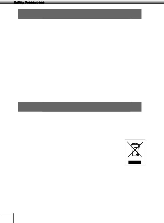
Action for Environment (WEEE)
To all user of Shimadzu equipment in the European Union:
Equipment marked with this symbol indicates that it was sold on or after 13th August 2005,
which means it should not be disposed of with general household waste. Note that our equipment is for industrial/professional use only.
Contact Shimadzu service representative when the equipment has reached the end of its life.
They will advise you regarding the equipment take-back.
With your co-operation we are aiming to reduce contamination from waste electronic and electrical equipment and preserve natural resource through re-use and recycling.
Do not hesitate to ask Shimadzu service representative, if you require further information.
For Caifornia, USA Only
This product contains a battery that contains perchlorate material. Perchlorate Material - special handling may apply.
See www.dtsc.ca.gov/hazardouswaste/perchlorate
WEEE Mark
X

Table of Contents
Foreword....................................................... |
I |
UP Series..................................................... |
III |
Safety Precautions..................................... |
IV |
Precautions on Use ............................................. |
IV |
■■Precautions Related to Usage.......................... |
IV |
■■Precautions Related to Place of Installation..... |
IV |
■■Precautions Related to Installation Work........... |
V |
■■Precautions Related to Work/Operations.......... |
V |
■■ Risks Involved in Repairs/Dismantling/ |
|
Modifications ............................................... |
V |
■■Precautions Related to Inspections/ |
|
Maintenance............................................ |
VI |
■■Measures to be Observed during |
|
Emergencies ........................................... |
VI |
■■Measures to be Observed during Power |
|
Outages................................................... |
VI |
■■Caution Labels................................................. |
VI |
■■Residual Risk Information............................... |
VII |
Aftercare Services and Part Supply Period.......... |
IX |
Inspections and Maintenance............................... |
IX |
Product Disposal.................................................. |
IX |
Shimadzu Balances and 21 CFR Part 11............... |
X |
Action for Environment (WEEE)............................. |
X |
Table of Contents........................................ |
XI |
1.Name and Function of Components..1
|
1.1 |
Components............................................. |
1 |
|
1.2 |
Key Panel and Operation.......................... |
3 |
|
1.3 |
Balance Display and Function.................. |
4 |
2. |
Installation............................................ |
5 |
|
|
2.1 |
Choosing the Installation Site................... |
5 |
|
2.2 |
Unpacking and Delivery Inspection.......... |
7 |
|
2.3 |
Installation.............................................. |
10 |
|
2.4 |
Turning on the Power.............................. |
15 |
|
2.5 |
Span Calibration..................................... |
16 |
3.Basic Operation The balance can be used correctly according to the
content of Chapters 1 to 4................ |
19 |
|
3.1 |
Weighing................................................. |
19 |
3.2 |
Changing the Unit Display...................... |
20 |
4.Menu Item Selection (Read Chapters
4 to 12 before using the balance)..... |
21 |
|
4.1 |
What is the Menu?.................................. |
21 |
4.2 |
Menu Map.............................................. |
21 |
|
4.3 |
Menu Item Selection Procedure............. |
22 |
|
|
4.4 |
Setting Numeric Values.......................... |
25 |
|
|
4.5 |
Related Useful Functions........................ |
26 |
|
|
|
4.5.1 |
Last Menu Recall....................... |
26 |
|
|
4.5.2 |
Returning to the Default Settings |
|
|
|
|
(menu reset)............................... |
26 |
|
|
4.5.3 |
Menu Lock................................. |
27 |
5. |
Built-in Clock Set-up......................... |
28 |
||
|
5.1 |
Date........................................................ |
|
28 |
|
5.2 |
Date Output Style................................... |
28 |
|
|
5.3 |
Time........................................................ |
|
29 |
|
5.4 |
Setting Display During Stand-by............. |
29 |
|
6. |
Display Selection............................... |
30 |
||
|
6.1 |
Bar graph display.................................... |
30 |
|
|
6.2 |
Changing the Minimum Display Digit...... |
30 |
|
7. |
Calibration.......................................... |
|
31 |
|
|
7.1 |
What is calibration?................................ |
31 |
|
|
7.2 |
Calibration Execution.............................. |
32 |
|
|
|
7.2.1 |
Span Calibration Using the Built-in |
|
|
|
|
Weight (UPX Series Only)........... |
32 |
|
|
7.2.2 |
Calibration Check Using the Built- |
|
|
|
|
in Weight (UPX Series Only)....... |
33 |
|
|
7.2.3 |
Span Calibration Using External |
|
|
|
|
Weights...................................... |
35 |
|
|
7.2.4 |
Calibration Check Using External |
|
|
|
|
Weights...................................... |
36 |
|
7.3 |
Calibration Setting.................................. |
37 |
|
|
|
7.3.1 |
Selecting the Calibration Type.... |
37 |
|
|
7.3.2 |
PSC Fully-automatic Calibration |
|
|
|
|
(UPX Series only)........................ |
37 |
|
|
7.3.3 |
Clock-CAL Fully-automatic |
|
|
|
|
Calibration (UPX Series only)...... |
39 |
|
|
7.3.4 |
PCAL: Calibration of the Built-in |
|
|
|
|
Weight (UPX Series only)............ |
40 |
|
|
7.3.5 |
PCAL Password Setting (UPX |
|
|
|
|
Series only)................................ |
41 |
7.4Maintaining Calibration Reports… GLP/ GMP/ISO Compliant Measurement
|
|
Management Systems............................ |
42 |
|
|
|
7.4.1 |
Calibration Report Setting.......... |
42 |
|
|
7.4.2 |
Balance ID Setting..................... |
42 |
8. |
Environment....................................... |
43 |
||
|
8.1 |
Overview................................................. |
43 |
|
|
8.2 |
Stability and Response (Averaging)........ |
43 |
|
|
8.3 |
Stability Detection and Settings.............. |
45 |
|
|
|
8.3.1 |
Stability Detection Band............ |
45 |
XI

Table of Contents
|
|
8.3.2 Timing of Stability Mark |
|
|
|
12.5.3 |
Format....................................... |
88 |
|
|
Illumination and Data Output |
..... 46 |
|
|
12.5.4 |
Communication Speed.............. |
88 |
|
8.4 |
Tracking.................................................. |
46 |
|
|
12.5.5 Parity / Bit Length...................... |
88 |
|
|
|
|
|
|
|
12.5.6 |
Stop Bit...................................... |
89 |
9. |
Unit Display Set-up............................ |
47 |
|
|
12.5.7 |
Delimiter..................................... |
89 |
|
|
9.1 |
Units |
47 |
|
12.6 Decimal Point Symbol in Output Data.... |
89 |
||
|
|
|
|
|
|
|||
|
9.2 |
Percentage (%) Conversion.................... |
48 |
13. |
Maintenance and Transportation |
90 |
||
|
|
|
|
|||||
10. |
Enhancing Productivity..................... |
49 |
|
13.1 |
Maintenance........................................... |
90 |
||
|
10.1 |
Checkweighing and Target Display |
49 |
|
13.2 |
Moving the Balance................................ |
90 |
|
|
|
|
|
|
|
|||
10.1.1Checkweighing (Comparator)
|
Display Type 1 |
50 |
14. |
Troubleshooting................................. |
91 |
|
|
|
|
|
|
||
10.1.2 |
Checkweighing (Comparator) |
|
|
14.1 |
General Display...................................... |
91 |
|
Display Type 2............................ |
50 |
|
14.2 |
Error Display........................................... |
92 |
10.1.3 |
Target Mode............................... |
51 |
|
14.3 |
Troubleshooting...................................... |
93 |
10.2 Piece Counting (PCS)............................. |
52 |
|
14.4 |
LCD (Liquid Crystal Display) Check........ |
93 |
|
10.3Automatic Printing and Output
|
(Auto Print).............................................. |
53 |
Appendices................................................ |
94 |
||
10.4 |
Automatic Compensation of Zero Point |
|
A-1. |
Specifications |
94 |
|
|
Drift (Auto Zero) |
55 |
||||
|
A-2. |
Menu Map |
96 |
|||
10.5 |
Sample Loading and Unloading |
|
||||
|
A-3. |
Standard Accessories and Maintenance |
||||
|
Determination (Zero Range) |
56 |
||||
|
|
Parts List |
101 |
|||
10.6 |
Taring/Printing at Stability |
57 |
|
|||
A-4. |
Optional Accessories List |
102 |
||||
10.7 |
Registering Container Weight (Pretaring |
|
||||
|
A-5. |
RS-232C/Specifications of Connectors.103 |
||||
|
Value) |
58 |
||||
|
A-6. |
Unit Conversion Coefficient List |
104 |
|||
|
|
|
||||
11. Application Functions |
59 |
A-7. |
Performance Checks............................ |
105 |
||
A-8. |
Below-Weigh Hook Dimensions |
106 |
||||
|
|
|
||||
11.1 |
Solid Specific Gravity Measurement....... |
59 |
A-9. |
Index..................................................... |
107 |
|
11.2 |
Liquid Density Measurement.................. |
62 |
|
|
|
|
11.3 |
Detecting Peak Values (Peak Hold)......... |
65 |
|
|
|
|
11.4 |
Outputting at Fixed Times (Interval Timer)........ |
67 |
|
|
|
|
11.5Measuring a Large Number of Small
|
Samples (Add-on Mode)......................... |
68 |
11.6 |
Animal Weighing mode........................... |
70 |
11.7 |
Formulation Mode.................................. |
73 |
12. Connections and Communications |
|
|
with External Equipment................... |
75 |
|
12.1 |
Connecting Printers................................ |
75 |
12.2 |
Connecting Personal Computers........... |
76 |
12.3Connecting PLCs and Other Serial
|
Communications Equipment.................. |
78 |
|
12.4 |
Cable Connections (RS232C)................. |
79 |
|
|
12.4.1 |
Connecting the Cable................ |
79 |
|
12.4.2 |
Data Format............................... |
80 |
|
12.4.3 |
Using Command Codes............ |
82 |
12.5 |
Communication Setting.......................... |
87 |
|
|
12.5.1 |
Overview.................................... |
87 |
|
12.5.2 |
Handshaking.............................. |
87 |
XII

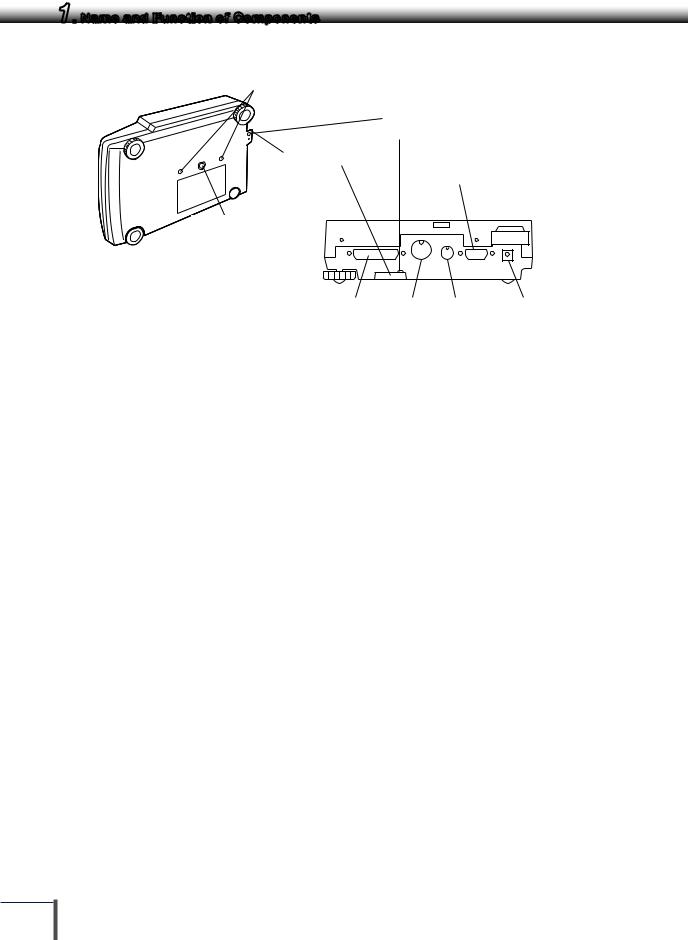
1. Name and Function of Components
1.1 Components
a. Large pan model
Label
Shows model name. "Max" and "d" are indications required by legal metrology, which do not restrict the weighing range in general use.
UP |
0 |
|
000x |
||
|
||
3 |
|
Operation keys
Used to tare, execute calibration and functions, program functions, input numerical values
Pan
Supports the object to be weighed
Large pan windbreak
Even light breezes can have an effect on measurements, so the windbreak protects against wind.
The windbreak is not included with models with a minimum display of 0.1 g.
Main body
Display panel
Shows weighed result, information on programming function, indicates current setting, working function,
necessary operation, and error message
Level screws
Adjust to level the balance
b. Small pan model (minimum display 0.001g, windbreak standard)
|
Windbreak set |
Pan |
Even light breezes can have an effect on |
measurements, so the windbreak protects against |
|
Supports the object to be weighed |
wind. |
Label |
|
|
Shows model name. |
|
|
"Max" and "d" are |
|
|
indications required by |
|
|
legal metrology, which do |
|
|
not restrict the weighing |
|
|
range in general use. |
U |
000x |
|
P0 |
|
|
3 |
|
Operation keys
Used to tare, execute calibration and functions, program functions, input numerical values
Main body
Display panel
Shows weighed result, information on programming function, indicates current setting, working function,
necessary operation, and error message
Level screws
Adjust to level the balance
1
2
3
4
5
6
7
8
9
10
11
12
13
14
1
1. Name and Function of Components
a,b. Common
Transportation screws
(only for UPX Series)
Ground terminal
Connect this terminal to ground if necessary
Theft preventing ring
KEY Connector
Below-weigh hook cap
RS-232C |
DATA I/O |
AUX |
DC IN |
Connector |
Connector |
Connector |
Connector |
(Connectors on the back)
2
1. Name and Function of Components
1.2 Key Panel and Operation
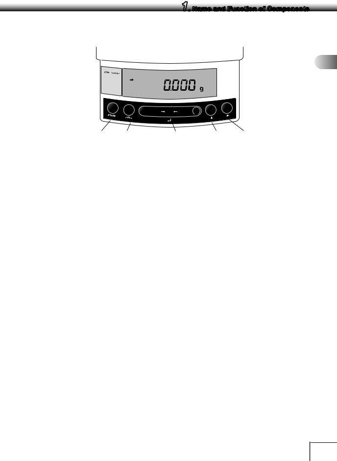
1
UP1023X
Max 1020g
d= 0.001g
POWE |
R |
CAL |
O/T |
UNIT |
|
|
|||||
|
|
|
|||
|
|
|
|
|
[POWER] key [CAL] key [O/T] key [UNIT] key [PRINT] key
Functions of the keys
Key |
During Weighing |
||
|
|
||
Press Once and Release |
Press and Hold for About 3 Seconds |
||
|
|||
|
|
|
|
[POWER] |
Switches between the operation and standby |
Exits the application function and returns to |
|
modes. |
the mass display. |
||
|
|||
|
|
|
|
[CAL] |
Enters span calibration or menu item selection. |
Displays the last menu item that was set. (Last |
|
(*1) |
menu recall) |
||
|
|||
|
|
|
|
[O/T] |
Tares the balance. (Displays zero.) (*2) |
Displays the Pretare value. (*6) |
|
|
|
|
|
[UNIT] |
Changes the weighing unit or selects the |
Switches between the 1d and 10d displays. |
|
specific gravity measurement. (*3) |
(*4) (*7) |
||
|
|||
[PRINT] |
Sends the displayed value to a peripheral |
Sends the date and time to a peripheral |
|
device. |
device. (*6) |
||
|
|||
|
|
|
|
*1 This key is used to set values when percent (%), number (PCS), solid specific gravity ( d), or liquid specific gravity (d) are displayed.
*2 When a Pretare value is set, zero is not displayed and [-Pretare value] is displayed.
*3 Units other than “g” must be set up before they can be used for measurement. Only gram (g), percent (%), and piece counting (PCS) are set-up before shipment.
*4 When the unit is set to 10d, the resolution of the minimum display is decreased by one decimal place.
*5 In Pouring mode (See 8.2), the right-most part of [O/T] key marked with a circle functions as the switch for environmental condition setting. Otherwise this part functions the same way as the other parts of [O/T] key.
*6 Either “Taring” (at a weight exceeding 2.0% of the capacity) or “Zeroing” ( at a weight within 2.0% of the capacity) takes place with a verified balance as a legal measuring instrument in using region.
*7 Not applicable to a verified balance as a legal measuring instrument in using region.
Key |
During Menu Item Selection |
||
|
|
||
Press Once and Release |
Press and Hold for About 3 Seconds |
||
|
|||
|
|
|
|
[POWER] |
Returns to the previous menu level |
Returns to the mass display. |
|
|
|
|
|
[CAL] |
Moves to the next menu item. |
Displays the last menu item that was set. (Last |
|
Menu Recall) |
|||
|
|
||
|
|
|
|
[O/T] |
Selects or sets the currently displayed menu |
No operation. |
|
item, or enter into the displayed menu. |
|||
|
|
||
|
|
|
|
[UNIT] |
Increases the numeric value of the blinking digit |
No operation. |
|
by 1. |
|||
|
|
||
|
|
|
|
[PRINT] |
Moves to the next digit during numeric value |
No operation. |
|
entry. |
|||
|
|
||
|
|
|
|
2
3
4
5
6
7
8
9
10
11
12
13
14
3
1. Name and Function of Components
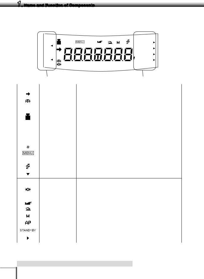
1.3 Balance Display and Function
|
|
|
HI |
# |
|
|
%NETBPTG |
|||
|
|
|
|
|||||||
|
|
|
|
|||||||
|
|
|
GO |
|
|
|
PCS lbGN |
|||
|
|
|
|
|
|
|||||
|
|
|
|
|
|
|||||
|
|
|
|
|
|
mg mom |
||||
|
|
|
|
|
|
|||||
|
|
|
|
|
|
|||||
|
|
|
|
|
|
|||||
|
|
|
|
|
|
|
|
|
kg ctdwt |
|
|
|
|
|
|
|
|
|
|
||
|
|
|
|
|
|
|
|
|
||
|
|
|
|
|
|
|
|
|
||
|
|
|
LO |
BATT AP |
WARM-UP STAND-BY |
oztl |
||||
|
|
|
||||||||
|
|
|
||||||||
|
|
|
||||||||
|
|
|
|
|
|
|
|
|||
|
Analog display section |
|
|
|
Unit display section |
|||||
|
|
|
|
|
|
|
|
|||
Display |
|
|
Name |
|
|
Description |
||||
|
|
|
|
|
|
|
|
|
||
|
|
Stability mark |
|
Indicates that the weighed value is stable. (*1) In menu item selection, this |
||||||
|
|
|
symbol indicates currently selected item. (*1) |
|||||||
|
|
|
|
|
|
|
||||
|
|
Tare symbol |
|
Indicates that a Pretare value has been set. (*3) |
||||||
|
|
|
|
|
|
|
|
|
|
|
|
|
|
|
|
|
|
Illuminates during span calibration. |
|
|
|
|
|
|
|
|
|
|
Blinks before automatic span calibration starts. |
|||
|
|
Weight symbol |
Note: Using a verified balance as a legal measuring instrument in |
|
||||||
|
|
using region: |
|
|
||||||
|
|
|
|
|
|
|
|
|
||
|
|
|
|
|
|
|
When PSC fully-automatic span calibration is not activated, operator must |
|
||
|
|
|
|
|
|
|
carry out span calibration with the built-in weight upon blinking of this symbol. |
|
||
|
|
|
|
|
|
|
|
|
|
|
|
|
|
|
|
|
|
|
|||
|
|
|
|
|
|
|
Note: Using a verified balance as a legal measuring instrument in |
|
||
[ ] |
|
|
Bracket |
|
using region: |
|
|
|||
|
|
|
|
|
|
|
The figure bordered by the bracket is the auxiliary indicating device. |
|
||
|
|
|
|
|
|
|
|
|
|
|
|
|
Number symbol |
Indicates numeric value entry. |
|
|
|||||
|
|
|
|
|
|
|
||||
|
|
Menu symbol |
|
Illuminates during menu item selection. |
|
|
||||
|
|
|
|
|
|
|
||||
|
|
|
Asterisk |
|
Indicates that the displayed numeric value is not a mass value. (*2) |
|||||
|
Communication symbol |
Illuminates during communication to external equipment through the |
||||||||
|
RS-232C or DATA I/O connector. |
|
|
|||||||
|
|
|
|
|
|
|
|
|
||
|
Inverse triangle symbol |
Indicates the set-up of solid specific gravity measurement. Used as a |
||||||||
|
substitution of the decimal point. |
|
|
|||||||
|
|
|
|
|
|
|
|
|
||
|
|
|
Indicates the set-up of Auto Zero function.(*3) |
|
|
|
|
|
|
|
|
|
Note: Using a verified balance as a legal measuring instrument in |
|
|
Zero symbol |
using region: |
|
|
|
|
|
Indicates that the balance is set exactly to "Zero" with the zero-setting |
|
|
|
|
function(+/- 0.20e: e = verification scale interval). |
|
|
|
|
|
|
|
Animal symbol |
Indicates the set-up of Animal Weighing function.(*3) |
||
|
|
|
|
|
|
Add-on symbol |
Indicates the set-up of Add-on mode or Formulation mode. |
||
|
|
|
|
|
|
Memory symbol |
Displays when the net total mass measurement function (memory |
||
|
function) is ON. |
|||
|
|
|
||
|
Auto Print symbol |
Indicates the set-up of Auto Print function. |
||
|
|
|
|
|
|
Stand-by symbol |
Illuminates when the balance power is in the standby mode. |
||
|
Also illuminates when the application function has entered the standby mode. |
|||
|
|
|
||
|
Response stability |
Displays to indicate response stability setting status. |
||
|
setting symbol |
|||
|
|
|
||
*1 |
Stability mark |
The displayed value may change while the stability symbol remains illuminated if the load is |
||
*2 |
|
changing slowly or if the stability detection band has been set to a large value. |
||
Decimal replacement |
If there are any decimals to the right of 7 digit numbers, this will be displayed to indicate the |
|||
|
|
presence of the decimals that are not displayed. |
||
*3 Not applicable to a verified balance as a legal measuring instrument in using region
4
2. Installation
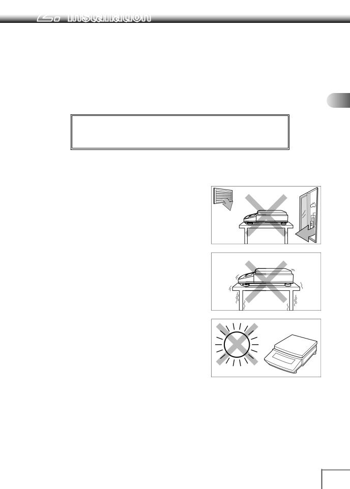
2.1 Choosing the Installation Site
(1)Power supply
Select an installation site with a power source that allows for proper use of the included AC adapter.
Verify that the supply power voltage conforms to that indicated on the AC adapter.
(2)Installation site
! Caution
Avoid sites where the balance will be exposed to the following:
•Air flow from air-conditioner, open window, or ventilator
•Vibration
• Direct sunlight
Continued
1
2
3
4
5
6
7
8
9
10
11
12
13
14
5

2.
 Installation
• Extreme temperature, temperature changes or humidity
•Corrosive or flammable gasses
•Dust, wind, electromagnetic waves, or magnetic fields
Install the balance on a strong and stable flat table or floor in the room.
Large capacity balances should be installed on a sturdy floor and table that can support the total load of the balance and object to be weighed.
6
2.
 Installation
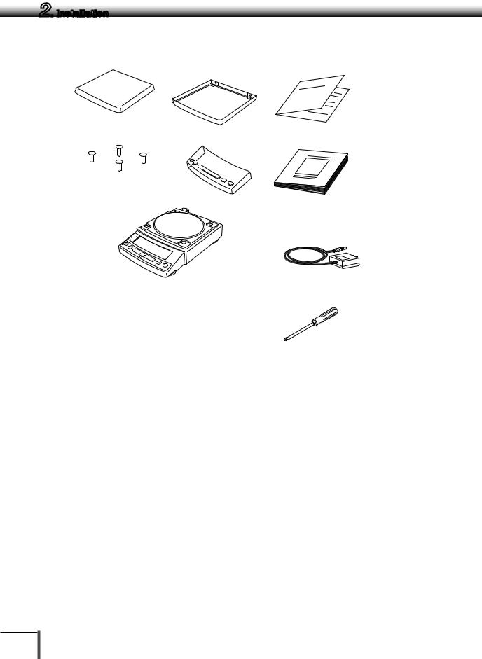
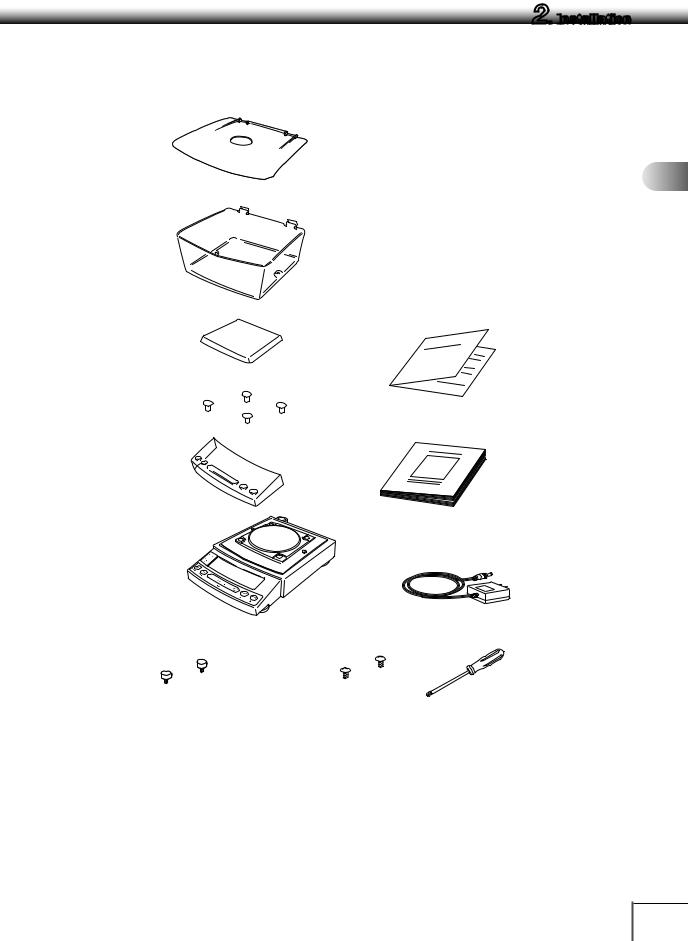
2.2 Unpacking and Delivery Inspection
Unpack and remove all the items from the delivery box. Check if all the listed items are present and nothing has been damaged. Contact your local distributor in case of damaged or missing items. Contact information is provided on Last page.
1 Standard packed item and quantity
|
|
a. Large pan model |
b. Small pan model |
|||
Type |
|
Minimum |
Minimum |
Minimum |
Minimum |
|
|
display |
display |
display |
|||
|
|
display d=0.1g |
||||
|
|
d=0.01g |
d=0.01g |
d=0.001g |
||
|
|
|
||||
Model |
|
UP4201X |
UP2202X |
UP422X |
UP223X |
|
|
|
UP8201X |
UP4202X |
UP822X |
UP423X |
|
|
|
|
UP6202X |
|
UP623X |
|
|
|
|
|
|
UP823X |
|
|
|
|
|
|
UP1023X |
|
|
|
UP4201Y |
UP2202Y |
UP422Y |
UP223Y |
|
|
|
UP8201Y |
UP4202Y |
UP822Y |
UP423Y |
|
|
|
|
UP6202Y |
|
UP623Y |
|
|
|
|
|
|
UP823Y |
|
|
|
|
|
|
UP1023Y |
|
Balance main body |
|
1 |
1 |
1 |
1 |
|
|
|
|
|
|
|
|
Pan supporter cap |
|
4 |
4 |
4 |
4 |
|
|
|
|
|
|
|
|
Pan |
|
1 |
1 |
1 |
1 |
|
|
|
|
|
|
|
|
AC adapter |
|
1 |
1 |
1 |
1 |
|
|
|
|
|
|
|
|
In-use protective cover |
|
1 |
1 |
1 |
1 |
|
|
|
|
|
|
|
|
Windbreak (for Large pan) |
0 |
1 |
0 |
0 |
||
|
|
|
|
|
|
|
Windbreak set (for |
Main |
0 |
0 |
0 |
1 |
|
Small pan) |
|
|
|
|
|
|
Lid |
0 |
0 |
0 |
1 |
||
|
||||||
|
|
|
|
|
|
|
|
Fixing knob |
0 |
0 |
0 |
2 |
|
|
|
|
|
|
|
|
Rubber cap |
|
0 |
0 |
2 (installed on |
2 (installed on |
|
|
|
|
|
balance main |
balance main |
|
|
|
|
|
body) |
body) |
|
Stainless screw |
|
0 |
0 |
2* |
2* |
|
|
|
|
|
|
||
Instruction manual (incl. operation |
1 |
1 |
1 |
1 |
||
explanation sheet) |
|
|||||
|
|
|
|
|
||
*In cases where there is any risk of organic solvents coming into contact with the main body, pull off the 2 rubber caps
from the top of the main body and fasten the included stainless steel screws in the holes.
1
2
3
4
5
6
7
8
9
10
11
12
13
14
7
2.
 Installation
a. Large pan model
■Pan |
■Large pan windbreak |
■Operation explanation sheet |
|
(0.01 g models only) |
|
■Pan supporter caps |
■In-use protective cover |
■Instruction manual |
■Balance main body |
■AC adapter |
|
(The shape of the adapter supplied with |
UP0000x |
the balance may differ from this gure.) |
|
■Screw Driver
8
2.
 Installation
b.Small pan model
■Windbreak Lid
(minimum display0.001g models only)
■Windbreak Main
(minimum display0.001g models only)
■Pan |
■operation explanation sheet |
■Pan supporter caps
■In-use protective cover |
■Instruction manual |
■Balance main body |
■AC adapter |
|
(The shape of the adapter supplied with |
UP0000x |
the balance may differ from this figure.) |
■Fixing knobs for windbreak |
■Stainless screws |
■Screw Driver |
minimum display0.001g models only |
|
|
1
2
3
4
5
6
7
8
9
10
11
12
13
14
9
2.
 Installation
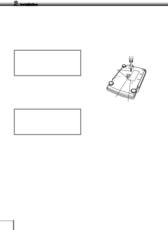
2.3 Installation
Start at step 3 when installing a UPY Series balance. Prepare a plus (+) screw driver for a UPX Series balance.
1 Place the balance main body upside down. (UPX only)
! Caution
Do not operate step 2 with the balance placed on its side. Place the balance on a smooth surface.
2 Referring to the explanation label on the bottom of the balance, turn the two transportation screws counterclockwise until they tighten again. (UPY only)
! Caution
When moving the balance again, turn the two transportation screws clockwise until they tighten. (UPX only)
3 Slowly and carefully turn the main body back over (right side up).
Transportation screws (only for UPX Series)
Below-weigh
hook cap Explanation label (only for UPX Series)
10
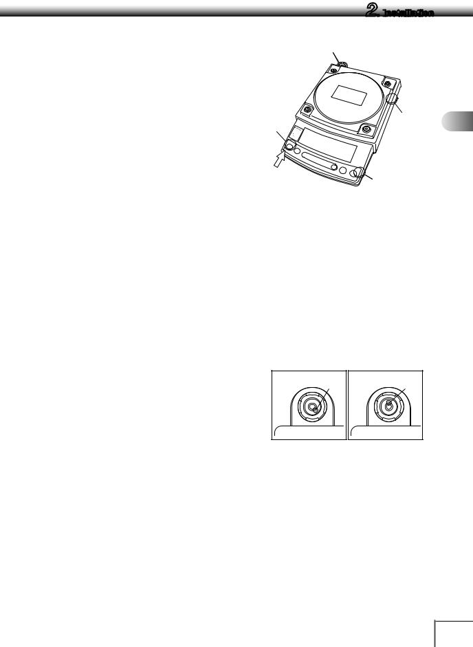
4 This balance has three level screws (adjustable feet) at the right front, left front and right rear corners.
Turning a level screw clock-wise stretches the leg to raise the balance body there. Turning anticlockwise withdraws the leg and lowers the balance body.
The level indicator locates at left rear. The bubble of it is off center when the balance is not placed level.
(1)At first, adjust only with the two front screws. Then, turn the right rear level screwanticlockwise to withdraw its leg completely.
While adjusting level screws and observing the bubble, gently press the left front corner of the balance so that both front level screw feet are touching the table surface.
(2)Bubble moves to the highest position. Therefore, adjust level screws so that the balance main body is lowered in the direction of the bubble.
Case 1: Right front of the balance is too high. Turn right front level screw anticlockwise so that the bubble moves towards center.
Case 2: Front of the balance is too low. Turn both front level screws clockwise so that the bubble moves towards center.
(3)When the bubble has come to the center of the red circle, turn the right rear level screw clockwise until its foot softly touches the table surface. Verify the balance sits stable with four feet.
2.
 Installation
Level indicator
Level |
|
screw |
83[ |
|
|
|
J |
Left front
Case 1 |
Bubble |
|
|
1 |
|
|
Level |
2 |
|
|
screw |
||
(At the shortest |
|
||
point when starting |
3 |
||
|
adjustment) |
||
|
|||
|
|
||
Level screw |
4 |
||
[Large pan model] |
|||
|
|||
|
|
5 |
|
|
|
6 |
|
|
|
7 |
|
|
|
8 |
|
|
|
9 |
|
Case 2 |
Bubble |
|
|
|
10 |
||
|
|
||
|
|
11 |
|
|
|
12 |
|
|
|
13 |
|
|
|
14 |
|
11
2.
 Installation
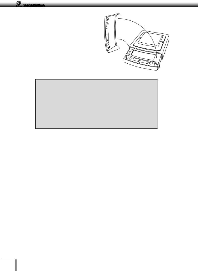
5 Install the pan. With small pan model with minimum display of 0.001g, the standard windbreak is also installed here.
a.Large pan model
(1)Insert the four pan supporter caps into the holes in the top of the balance.
(2)Next, align the large pan windbreak with the frame and set in place
(3)Lastly, set the pan so that the positioners on the back of the pan precisely align with the pan supporter caps as shown in the figure.
Positioners
Pan
Curved
front
Pan supporter caps
 83 [
83 [
b.Small pan model (minimum display 0.01g ∙ No
windbreak)
Insert the four pan supporter caps into the holes in the top of the balance. Place the pan gently on pan supporter caps. Positioners of the pan must fit pan supporter.
The rubber caps on top of the main body may be replaced with the stainless screws so that it will be more secure when exposed to organic solvent.
Positioners
Pan
Curved
front
Pan supporter caps
 83 [
83 [
b.Small pan model
(minimum display 0.001g, windbreak standard)
(1)Pull out the two rubber caps from the main body top.
83 [


Large pan windbreak (0.01 g models only)
Rubber caps
12

(2)Fit windbreak main on top of the balance main body, and fasten it with two fixing knobs. In cases where there is any risk of organic solvents coming into contact with the main body, use the included stainless steel screws to fasten the windbreak instead of the fixing knobs.
(3)Insert the four pan supporter caps into the holes in the top of the balance. Place the pan on them. Positioners on the pan must fit pan supporter caps.
(4)Place windbreak lid on top of windbreak main fitting the hinge parts.
2.
 Installation
UP0000x
 3
3 
Curved front
Pan supporter caps
83 [


83 [


Pan
Hinge parts
1
2
3
4
5
6
7
8
9
10
11
12
13
14
13
2.
 Installation
6 If you use in-use protective cover, peel off the paper to expose the adhesive on it, then fit it on the display and key part. Press the adhesive parts gently.
UP0000x
 3
3 
Note
Using a verified balance as a legal measuring instrument in using region:
Legal regulations require a verified balance be sealed. This control seal is a self-destructive adhesive label. This seal is irreparably damaged invalidating the verification, if you attempt to remove it. The balance must then be reverified before it is used for legal measurements.
14
2.
 Installation
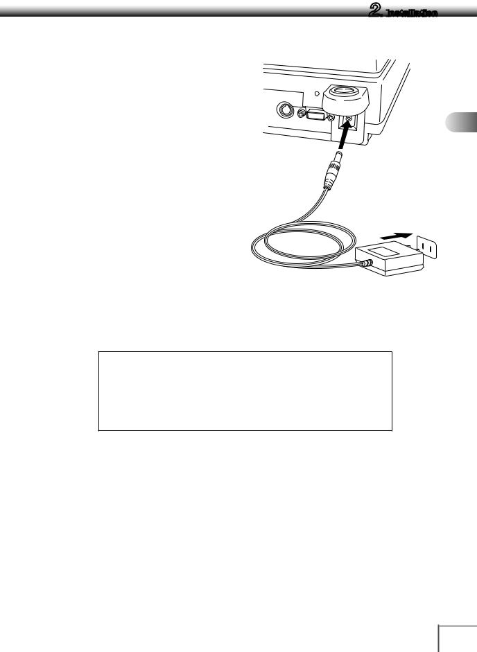
2.4 Turning on the Power
1 Insert the AC adapter plug into the DC IN connector on the back of the balance.
2 Insert the AC adapter into the power source. The balance self-check is activated and the following messages are displayed in the order indicated.
First, the software version number is displayed. (Balance self-check display)
[5.00:00]→[CHE 5]→[CHE 4]→ [CHE 3]
→[CHE 2]→[CHE 1]→[CHE 0]→ prompting all the symbols and segments →[oFF]
* e.g. of the version number
([CHE 5] and [CHE 4] are not displayed for the UPY Series)
3 Press [POWER] key.
All the symbols and segments prompt and then the display changes to indicate the gram-display. The backlight is illuminated.
Note
If display all mode (→14.4) is selected, the balance will stop in the display all state.
Press the [O/T] key afterwards to switch to g display.
*The actual AC adapter shape may be different.
1
2
3
4
5
6
7
8
9
10
11
12
13
14
15

2.
 Installation
2.5 Span Calibration
Note
Using a verified balance as a legal measuring instrument in using region:
Span calibration must be performed once the balance is installed and before using the balance as a legal measuring instrument in using region. Span calibration must be performed with the internal calibration weight to
maintain the verification valid. The balance must be connected to power and warmed up for at least 2 hours prior to span calibration and use as a legal measuring instrument.
It is necessary to calibrate the balance after it is moved.
Verify that the balance is stable before performing the span calibration. To achieve a very stable state, ensure that the balance has been turned on with the gram-display for at least one hour, that the temperature is constant, that there are no breezes or vibrations and that the balance is in an area isolated from the normal traffic flow.
Note
When carrying out span calibration, it is necessary to make sure the balance is as stable as possible. In order to ensure this stability, turn the power to the g display for at least 1 hour and allow the temperature of the balance to stabilize after installation, before carrying out calibration.
UPX Series
[Span Calibration Using the Builtin Weight]
1 Verify that the balance is in gram-display and that the pan is empty.
2 Press the [CAL] key once. “i-CAL” is displayed.
3 Press the [O/T] key.
After [i-CAL3] ~ [i-CAL 1] , [SEt] , [CAL End]are displayed indicating the completion of span calibration, the gram-display will appear.
This is the standard calibration type. Refer to " 7 for Calibration".
16
 Loading...