


 Loading...
Installation Guide
For
UD 150L-30 EX/FX
UD150L30-FX/EX Installation Guide, REV_B |
Page 1 of 35 |
Contents
1. General information
1.1Component location
1.2Mandatory modification
2. Connection of the system
2.1Power transformers
2.2Cable connection
3. Settings and adjustments
3.1Settings
3.2Adjustments
4. Appendix
A.Mandatory modification
B.List of error message
C.List of Potentiometers
D.List of LEDs
E.Initial Setting for Software
F.Fluoro mA setting
G.RAD60 and RAD 56 tube data
UD150L30-FX/EX Installation Guide, REV_B |
Page 2 of 35 |

1. General information
•Component location
Before starting the installation, locate all major components and PCBs in the generator. Following three figures is the illustration for component location.
Figure 1-1 Front View of UD150L-30/FX
UD150L30-FX/EX Installation Guide, REV_B |
Page 3 of 35 |

Figure 1-2 Front view of UD150L-30/FX (open swing panel)
UD150L30-FX/EX Installation Guide, REV_B |
Page 4 of 35 |

Figure 1-3 Back view of UD150L-30/FX
UD150L30-FX/EX Installation Guide, REV_B |
Page 5 of 35 |

2. Connection of the system
2.1 Power transformers
•A step down transformer, (XAT-2) is normally shipped together with this generator for installation. This transformer can provide proper power input for UD150L-30 FX/EX generator, YSF/RS table system, HMS/AID high-speed starter, and other peripheral accessories.
•There are two other transformers in UD150L-30 FX/EX generator are power related, T1 and T2 transformer. It is necessary to change taps for these two transformers according to the supplied input from XAT-2 before proceeding.
(1) T1 transformer,
For example, if the incoming power is three-phase 400V from XAT-2, connect AIN-0 to –A200 and AIN-2 to A200.
(2) T2 transformer,
Connect T2-0 to –200 and T2-2 to 200 base on the same assumption as (1).
2.2 Cable connection |
|
|
|
|
|
|
||||
• Power cable |
|
|
|
|
|
|
||||
Hospital breaker (3 φ 480V) |
XAT-2 transformer (3 φ 400V) |
Control cabinet |
||||||||
U |
|
|
|
|
|
|
|
|
UN |
Power terminal |
|
|
|
|
I/P |
O/P |
|
|
|||
|
|
|
|
|
||||||
V |
|
|
|
|
I/P |
O/P |
|
|
VN |
|
|
|
|
|
|
|
|||||
W |
|
|
|
|
I/P |
O/P |
|
|
WN |
|
|
|
|
|
|
|
|||||
GND |
|
|
GND |
GND |
|
GND |
Terminal block |
|||
|
|
|||||||||
Note: Only ground one end of the shielding on the three-phase power cable to prevent ground loop from happening. Refer to Fig. 2.4.3 in the installation manual.
• Control console |
|
|
|||
Control console |
|
Control cabinet |
|||
J62 |
|
|
J 62 |
System LF 30 PCB |
|
|
|
||||
J 63 |
|
|
J63 |
I/O LFX PCB |
|
|
|
||||
Frame |
|
GND |
Terminal strip |
||
|
|||||
J9 |
|
Hand Switch |
|||
|
|||||
•High speed starter (HMS or AID)
Connect JS1 cable between SYSTEM-LF 30 PCB and high speed starter by using JS1 connector kit in the accessory package shipped with this generator.
Following table is the description of the signal used for high speed starter
Signal |
Meaning |
Signal |
Meaning |
2 |
Normal speed rotation |
1M |
Tube 1 selection |
7 |
High speed rotation |
2M |
Tube 2 selection |
H2 |
Normal speed confirmation |
SBK |
Starter fault signal |
H7 |
High speed confirmation |
CM1 |
Return for 7, H7, and SBK (0V DC) |
F |
Fluoro tube rotation |
CM2 |
Return for 2 and H2 (+15V DC) |
SP1 |
Spot film |
CM3 |
Return for F and SP1 (L0) |
|
|
CM4 |
Return for 1M and 2M (+15V DC) |
UD150L30-FX/EX Installation Guide, REV_B |
Page 6 of 35 |

The procedures to set up or programming the starter can be found in the installation and service manual of HMS-3. Follow the instruction in Section 6 on page 11. (X-ray tube must be connected to perform setup mode.)
•Table power
If a SHIMADZU table is to be installed, connect 3 φ 200 V from XAT-2 step down transformer to the power input terminal block for table.
•Table interface with generator
|
UD150L-30 FX |
|
|
|
|
YSF-220 |
|
|
|
|
|
J7 EXTENSION PCB |
|
CN36 GENERATOR |
|
|
I/O LFX |
J7 |
|||||
|
|
J7 |
CN36 |
|
I/F PCB |
||
|
|
|
|
|
|||
|
|
|
|
J8 |
|
|
|
|
MOTHER2-LF30 |
|
|
|
|
||
|
|
|
|
|
|
||
|
|
J8 |
|
|
|
|
|
|
|
|
|
|
|
|
|
UD150L30-FX/EX Installation Guide, REV_B |
Page 7 of 35 |
|
|||||

•Bucky connection
CAUTION: If UD150L30-FX is equipped only with SHIMADZU Bucky, YOU MUST DISCONNECT CABLES between TERMINAL-LF30 and TERMINAL LFX PCB. This includes 1B11, 1B1, 1B22, 1B2, 2B11, 2B1, 2B22, and 2B2 terminals on TERMINAL-LF30 PCB. Tape all disconnected terminals separately and secure them with other cables. Then connect Bucky cable directly to TERMINAL-LF30 PCB as stated below. Fail to disconnect the cable between these two boards will damage TERMINAL-LF30 PCB.
CONNECTION OF SHIMADZU BUCKY SYSTEM
TERMINAL-LF30 PCB |
SHIMADZU BUCKY |
|
L 100 |
X 2 |
|
|
|
|
|
L 100 |
|
||
|
1B11 |
|
|
||
|
|
## |
B1 |
GRID MOVING |
|
|
1B1 |
L 100 |
|||
24 V DC |
|
|
|
CONFIRMATION |
|
1B22 |
L 100 |
B2 |
AC POWER TO |
||
|
|||||
|
|
|
|
DRIVE BUCKY |
|
|
|
|
L 0 |
GRID MOTOR |
|
K 31 |
1B2 |
|
|
||
|
|
|
|||
* 1B 22 |
|
|
|
||
|
|
|
|
||
Note 1 24 V DC |
|
|
|
||
K 27 B |
|
|
|
|
|
BUCKY 1
* XOK
Note 2
K 25 A
## Add Jumper
L 0
Note 1: *1B22 is a DC signal within TERMINAL-LF30 PCB. When selecting Bucky1, 1B22 is at DC ground. However, 1B22 at terminal X2 is a AC 100 volt power supply to drive grid motor in Bucky. DO NOT mix these two signals by adding any extra jumpers for trouble shooting purpose.
Note 2: *XOK is the signal to turn on X-ray. Can be found in SYSTEM-LF30 PCB print 10/18. (M74A pin 2)
UD150L30-FX/EX Installation Guide, REV_B |
Page 8 of 35 |
CONNECTION OF NON-SHIMADZU BUCKY SYSTEM
TERMINAL-LF30 |
TERMINAL-LFX |
NON-SHIMADZU BUCKY |
L 100 |
|
X 2 |
JD 2 |
|
|
|
X0 1D |
|
|
4 |
1 |
|
|||
|
|
|
9 |
|
1 B11X |
||
|
1 B11 |
|
3 |
2 |
|
||
|
|
|
JP 2C |
|
|
|
|
|
|
|
|
|
|
|
|
|
|
|
8 |
JB 2B |
|
|
|
|
1 B1 |
|
|
|
|
|
|
24 V DC |
|
|
JB 2A |
|
|
1 B1X |
|
|
|
|
|
|
|||
K 27 B |
1 B22 |
|
1 |
L 100 |
|
|
X0 1E |
BUCKY 1 |
|
|
|
||||
24 V DC |
|
|
|
|
|
|
|
|
K 31 |
|
|
K 03 |
9 |
1 B22X |
|
|
|
2 |
|
|
|
|
|
|
1 B2 |
|
|
|
|
|
|
* 1B22 |
|
|
|
|
10 |
1 B2X |
|
|
|
|
L 0 |
|
|||
|
|
|
|
|
|
|
|
|
* XOK |
|
|
|
|
|
|
CONFIRMATION OF GRID MOVING
RETURN SIGNAL
POWER SUPPLY TO DRIVE GRID MOTOR
GRID MOTOR
|
|
CAUSION: MAKE |
SURE THERE |
|
L 0 |
||||
HAS NO JUMPER |
CONNECTED HERE |
|||
•Change jumper positions according to the voltage on 1 B11X.
JP 2C: AC 100-125 V |
JP 2B: DC 24 V |
JP 2A: DC 12 V |
Jumper position of JP 2A, JP 2B, and JP 2C depends on the voltage of from 1 B11X, grid confirmation signal provided by the Bucky system. If Bucky provide a 24 V DC signal to 1 B11X, when grid is moving, install JP 2B to 1-4 position, and JP 2C, JP 2A to 2-3 position. Then connect 1 B1X to 24 V DC ground. Make sure only one jumper is installed on 1-4 position and the other two on 2-3 position.
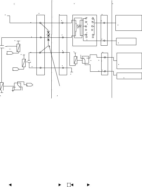
•Connection of I. I. Mag. mode selection signal
I.I. Mag. mode signal is connected via a new cable, I.I. View-field switching cable (P/N 532-15191) provided for this generator. This cable connects between JSK terminal on TERMINAL-LF30 PCB and IS connector attached to I.I. (Refer to Circuit diagram SYSTEM-LF30 15/18)
|
UD150L-30/FX |
YSF series table |
|
|
||||
|
TERMINAL-LF30 PCB |
GENERATOR I/F PCB |
||||||
|
|
|
IS |
|
|
|
|
|
JSK |
J9C |
|||||||
|
View-field switching cable |
|
|
|||||
|
|
Adapter |
|
|
||||
UD150L30-FX/EX Installation Guide, REV_B |
Page 9 of 35 |

• I.I. mode signal for under table collimator |
|
|||
UD150L-30/FX |
YSF series table |
|||
TERMINAL-LF30 PCB |
GENERATOR I/F PCB |
|||
|
|
|
|
XS |
|
JXS |
|||
|
cable (collimator control) |
|||
|
XS |
Adapter |
||
•I.I. Mag. Mode selection output
TERMINAL-LF30 PCB has several terminals for I.I. Mag. mode output selection. These terminals are IF0, IF1, IF2, IF3, and IF4. Mag. mode output is to provide interface for Digital products. IF signals are routed through the onboard relay contacts.
TERMINAL-LF30 PCB |
|
INFIMED or CAMTRONICS |
Common (DC24V) |
[IF0] |
Common |
Non-Mag. |
[IF1] |
|
Mag1 |
[IF2] |
Mag 1 |
Mag2 |
[IF3] |
Mag 2 |
Mag3 |
[IF4] |
Mag 3 |
Note: Same signal names used to be the I.I. Mag. mode selection input to the previous models of the X-ray Generators. With new UD150L-30/FX, these signal names are used for the output.
•I.I. cable connection
New cable connector is provided to improve the installation quality.
UD150L-30/FX |
I.I. |
||||
TERMINAL-LF30 PCB |
POWER SUPPLY |
||||
|
|
|
|
|
|
|
JTH-RB |
|
|
||
|
|
|
|
|
|
•PMT cable from I.I.
When using photomultiplier tube for digital exposure (IFG technique) and fluoro IBS regulation, connect PMT cable for I.I. as the following table.
PH POWER-96 PCB |
Phototimer signal cable |
|
M1 |
M1 |
(-HV) |
M2, M3 (common) |
M2, M3 |
|
M4 |
M4 |
(Signal) |
E |
E |
|
•Fluoro IBS signal connection, case 1
In case of using PMT to regulate Fluoro IBS, add a jumper between CP6 on PH-POWER PCB to TV7 on ANALOG-LF30 PCB (X1 pin3).
UD150L30-FX/EX Installation Guide, REV_B |
Page 10 of 35 |
• Fluoro IBS signal connection, case 2
When using TV signal to regulate fluoro IBS, a shielded co-axial cable should be connected from TV camera to ANALOG-LF30 PCB.
UD150L-30/FX |
|
TV system |
|
ANALOG-LF30 PCB |
TV 7 |
IBS signal |
Shielded cable |
|
TV 2 |
0 V |
|
• Photo timing connection
• |
For SHIMADZU Bucky with SPT photo timing connection, check the installation manual section 6.2. |
|
• |
If you programmed the Comet Chambers to Detector 2, follow the stated below diagram for |
|
|
connection. |
|
|
Comet Chamber |
PH CONT-98 PCB |
2
Left |
|
Field |
5 |
|
|
|
3 |
Right |
|
Field |
4 |
|
|
SIGNAL |
|
|
|
1 |
1 |
|
2 |
|
2 |
|
||
|
|
SIGNAL |
3 |
|
3 |
|
||
4 |
4 |
|
PLUG |
CN2-DTA |
|
|
|
1 |
1 |
|
|
|
1 |
SIGNAL |
|
Center |
|
|
|
|
|
|
|
||
|
|
||||||||
|
6 |
|
|
|
|
|
|
||
|
|
|
|
|
|
||||
Field |
2 |
|
|
|
2 |
|
|||
|
|
|
|
|
|
|
|
||
|
|
|
|
|
|
|
|
|
|
|
|
|
|
|
|
|
CN2-DTB |
||
|
|
|
|
Plug |
|
||||
in case of DET 2
You can change the connection anyway you like. Just make sure the connection stay in the same group. For example,
CN1-DTA and CN1-DTB are for Detector 1 CN3-DTA and CN3-DTB are for Detector 3
UD150L30-FX/EX Installation Guide, REV_B |
Page 11 of 35 |
Loading...