

Sherwood S-9500c Service Manual
SI{ER\
TOOD
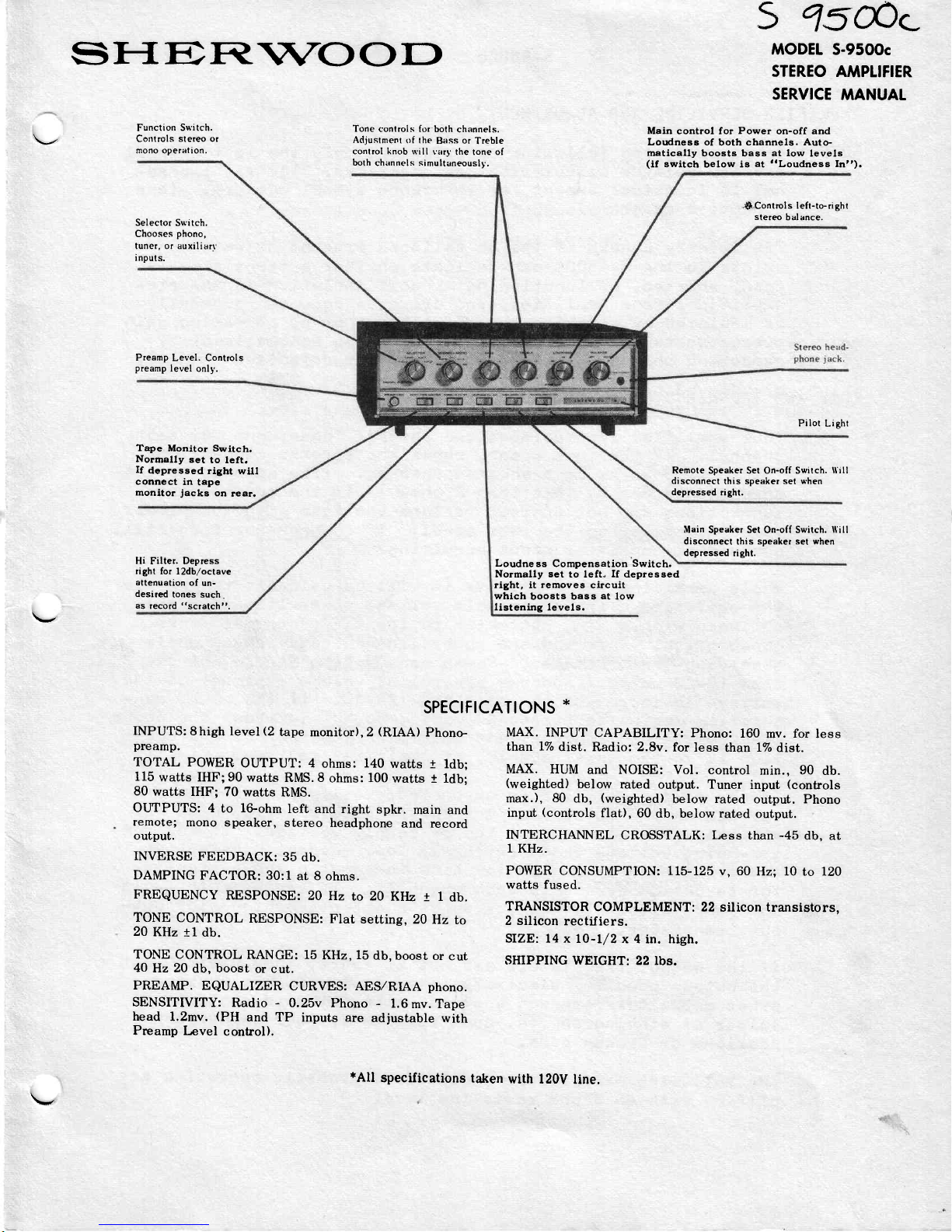
Function
Switch.
Controls
stereo or
mono operation.
Selector Switch.
Chooses
phono,
tuner, or auxiliarr
inputs.
Preamp
Level. Controls
preamp
level
only.
Tape Monitor
Switch.
Normally
set
to left.
If
depressed
right
will
connect
in
tape
monitor
jacks
on
rear.
Hi Filter. Depress
right
for l2db,/octave
attenuation
of un-
desired
tones such.
as
record
"scratcht'.
INPUTS:8high
level
(2
tape
monitor),2
(RIAA)
Phono-
preamp.
TOTAL
POWER
OUTPUT: 4
ohms:
140
watts
i ldb;
115
watts IHF;90
watts
RMS.8
ohms:
100
watts t ldb;
80
watts
IHF;
70
watts RMS.
OUTPUTSz 4
to
lGohm
left and right
spkr.
main and
remote;
mono speaker,
stereo
headphone
and record
output.
INVERSE
FEEDBACK:
35
db.
DAMPING
FACTOR: 30:l
at 8
ohms.
FREQUENCY
RESPONSE:
2O Hz
to 20
KlIz r 1
db.
TONE
CONTROL
RESPONSE:
FIat setting,
20
Hz
to
20
KHz
tl db.
TONE
CONTROL RANGE: 15
KHz,
15
db,
boost or
cut
4O
Hz 20
db,
boost
or cut.
PREAMP.
EQUALIZER
CURVES:
AES,zRIAA phono.
SENSITIVITY:
Radio - 0.25v Phono
-
1.6
mv.
Tape
head
1.2mv.
(PH
and TP
inputs
are
adjustable
with
Preamp
I-evel
control).
Tone controls
for both
channels.
Adjustment
of the
Bass
or
Treble
control knob will
varl'
the tone of
both
channel s simultaneouslv.
5
1s&c
MODEI
S-95OOc
STEREO AMPLIFIER
SERVICE
MANUAL
Main control for Power on-off and
Loudness of
both channels.
Auto-
matieally
boosts bass
at low
levels
(if
switch
below
is
at
t'Loudness
Int').
.S-.Control
s left-to- ri
ght
stereo
balance.
Pilot
Light
Remote
Speaker Set On-off Switch.
ll'ill
disconnect
this
speaker set when
depressed right.
Main Speaker Set
On-off Switch.
lf ill
disconnect
this
speaker set urhen
depressed
right.
Loudne
ss Compensation
Switch.
Normally set
to left"
If
depressed
right, it removes
circuit
whlch
boosts bass
at
low
listening levels.
SPECTFICATIONS
*
MAX. INPUT
CAPABILITY: Phono:
160
mv.
for
less
than
1%
dist.
Radio:
2.8v.
for less
than
1%
dist.
MAX.
HUM
and NOISE:
Vol. control
min.,
90
db.
(weighted)
below rated
output. Tuner
input
(controls
max.), 80
db,
(weighted)
below
rated
output. Phono
input
(controls
flat),
60
db, below
rated
output.
INTERCHANNEL
CROSSTALK: Less
than
-45
db, at
1
KHz.
POWER
CONSUMPTION:
115-125 v, 60
Hz; 10
to l2O
watts fused.
TRANSISTOR
COMPLEMENT:
22
silicon
transistors,
2 silicon
rectifiers.
SIZE:
14 xl0-L/2
x 4
in.
high.
SHIPPING WEIGHT:
22 lbs.
*All
specifications
taken
with l20V
line.
5-9
500c
AMPLIFIER
SERVICING AND
ADJUSTMENT
NOTE:
To
simplify the following
descriptions only
the left channel
and
its related circuitries are
deseribed. The
right chan-
nel is identical except
for reference
symbol numbers.
(
see
schQmatic
diagrams
)
Preliminary
checks
of the
dc
voltages
present
at various
points
in
the
5-9500c
can indicate
whether a transistor
is
open, shorted, or
functioning.
FauLt
isolation
in
the
pre-
amplifier, tone
amplifier, and driver stages can
g
enerally
be
isolated
by
checking
the dc
voltages or by comparing
gain
measurements
of
1
KHz
as
indicated
on the
schematic
or
by
comparing
the operating channeL
with
the defective channel.
FUSE AND
SPEAKER
5Y5TEM
CHECKS:
Your amplifier
incorporates
two
speaker
fuses, one
for each
channel.
If
the fuse opens,
check
the
speaker
connections
for shorted
wires ox
a shorted
speaker.
(The
speaker
resist-
ance should
not
be less
than
4
ohms.)
If
the
speaker
and
connections
are
not
shorted
replace
the fuse
with
the
Proper
val-ue as marked
on
the rear
panel.
If
the
speaker
fuse
still
opens
your
amplifier needs
servicing.
lrr/hi1e
servicing
the
ampli.fier
it
will-
be valuabl-e
to
opergte
the
amplifier using
a variable
voltage
power line
(VnnIAC)
equipped
with a line
wattmeter
to identify
abnormal
power
consumption.
Increase
the
power line
voltage upward
while
observing
the wattmeter.
Power
consumption
shoul-d
not ex-
ceed t
O-20
watts ( loudness
control
at
volume
minimum
)
.=
the
voltage
is increased
to
the
rated 1ZBVAC.
If the
power
con-
sumption
begins
to
exceed
2A watts,
do
NOT
increase
the
Power
line
voltage
any
further
and
determine
whether
the
malfunc-
tion
is in
the
power
supply,
oI
amPlifier
section.
If the
power amplifier
is
suspected,
verify
center-point
voltage
on the
dc side
of
the
output
el-ectrolyticr_C29O
for
app=o*imately
one-hal-f
of
the
B+
supply
voltage.
If the
cen-
ter-point
voltage
reads
extremely
]ot
r
susPect
a defective
output
transistor
on
the l-ow
side
(schematic
shows
transis-
tor
as
bottom
device
in
each channel
)
.
If
center-point
volt-
age
reads
extremely
high
r
suspect
a
defective
high
side
out-
put
transistor.
If the
output
transistors
are
not
at
fau1t,
then
verify
that
the
output
coupling
electrolytic
capacitor
is
not
shortedt
other
capacitors
are not
shorted,
circuit
board
contains
no
sol-der
or
etching
shorts,
open
resistors
r
poor
solder
con-
nections
or
broken
pads.
The following
perfoxmance
indicates
a
properly
operating
am-
plif
ier
with
an
I ohm
.resistive load.
v
\-1
 Loading...