

Sherwood S-9500 User Manual

5-9500
50 WATT
ALt
SILICOI\
II\TEGRATED
TRAI\SISTOR AMPTIFIER
Funclion
Switch
conlrols
slereo or
mono
operolion.
5elects
left
ond
right
input
chon-
nel
simultoneously.
Phono
Goin.
Contr
preomp
level
only.
Tope Monitor
Switch.
Normolly
set
to
left,
will
connect in tope
monitor
iock
on reor
if
switched to right.
Tone
controls
for both
chonnels.
Adjustment of
the
Boss
or Treble
conlrol
knob will vory
the tone
of
both
chonnels
simu ltoneously.
'Ff
i.-fTtttil:''*Sfi
i tch'
ro
right
for
l2dbloctove
otlenuotion
of un-
desired
lones
such
os record
"scrolcht'.
Moin
control for Power
on-off ond
Loudness
of
both
chonnels. Auto-
moticolly
boosts boss
ot
low.levels
(if
swirch
below
ol
"Loudness
In").
Controls
left-to-right
stereo bolonce
Pilot
Lighr
Speoker
"on-off"
switch.
Normolly
set
to
left, will
di sconnecl speokers
when
switched
to right.
Loudness
Compensotion
Switch.
Normolly
set to
left,
will remove
circuit
which
boosts
boss
ot low
seftings
of Loudness
control if
switched to right.
DESIGN
-CENTER
SPECI FICATIONS*
IN PU
TS:
6
high
level
(2
tope
monitor),
2
(RIAA)
Phono-preomp.,
2
(NAB)
topeheod
preomp.
POWER
OUTPUT:
Stereo-Eoch
chonnel
Zs
wotts music
power
(20
wotts continuous)
ot
1.5%
llt
distortion
(60c:7kc/4:1).
0UTPUTS:
4
to
16-ohm
left
ond
right
spkr.;
stereo
heodphone
ond record
output.
INVERSE
FEEDBACK:
45db.
DAMPING
FACTOR:
l5:l
ot 8 ohms.
FREQUENCY
RESPONSE:
(20w)
20cps
to
20kc
tl
db.
TONE
CONTROL
RESPONSE:
Flot
setting,
20
cps to
20
kc
tl
db.
TONE
CONTROL
RANGE:
l5
kc,
I5db.
boost
or cut.
40
cps.
l6db.
boost
or cut.
MAX.
INPUT
CAPABILITY:
Phono:
35mv.
for less
thon
.1%dist.
Rodio:
2.8v.
for
less thon
.l%
dist.
*Att
specificati,ons
with
120V
AC
line.
PREAMP. EQUALIZER
CURVES:
AES/RIAA
phono
ond NAB
tope.
SEN SITIVITY:
Rodio-0.
25v.
Phono-l
.8mv.
Tope
heod-,8mv.
(PH
ond TP
inputs ore
odiustoble
with
Phono
Goin control).
MAX.
HUM
ond
NOISE:
Vol.
control
min.,
90db.
(weighted)
below
roted
output.
Tuner input
(controls
moxi-
Iym),
B0db.
(weighted)
below
rored
ourpur.
Phono
input (contuols
flot),
70db.
bel'ow
roted
output.
INTERCH
ANN
EL
CROSSTALK:
Better
thon
-
45db
ot I kc.
POWER
CONSUMPTION:
ll5-125v,
60
cps;
l0
to
100
wotts fused.
TRANSI
STOR
COMPL
EMENT:
20
si I
icon
tron
sistors
2
si I icon
rectif
iers
SIZE:
ll
x
l2Yzx
4in.
hish.
SHIPPING
WEIGHT:
20
lbs.
INFORMATIO
s-9500
sERVlclNG
VOTTAGE
CHECKS
Preliminary
checks
of
tlte
D.C. voltages
present
at
various
points
in
the 5-9500
can
i"ove
useful
in
locating
defective componenttil
They are
inconclusive,
however,
in
determin-
ing
if
transistors
are operating
properly
in
all
aspects.
They
can only
indicate
whether
the
transistor
is
open,
shorted
or
fgnctioning,
not
how
well the
transistor is
functioning.
IN
GENERAL:
Correct
voltages
indicate a functioning
transistor.
The
same
voltage at the
colleetor
4nd
emitter
indicates a
shortedtransistor.
FUll
supply
voltage
on
the collector
and
no
voltage on
the emitter indicates
an
open
transistor.
OUTPUT
TRANSISTOR
BIAS
Of all
the
specifications which require
eheck-
ing
to
ascertain
eorrect
performance
of
the
S-9500,
proper
output
transistor
operation
is
the
most important and critieal.
Adjustment
of the output transistor
bias is necessary
if
output
transistors
are replaced*,
or the
amplifier
exhibits
one
or more
of
the follow-
ing symptoms:
1. Overheating
of
the output
transistors
under normal operating
conditions.
2.
Excessive
low level Intermodulation
Distortion more
than
0.t%
at 1.5
volts
across
I
ohms
(0.28
watt
output).
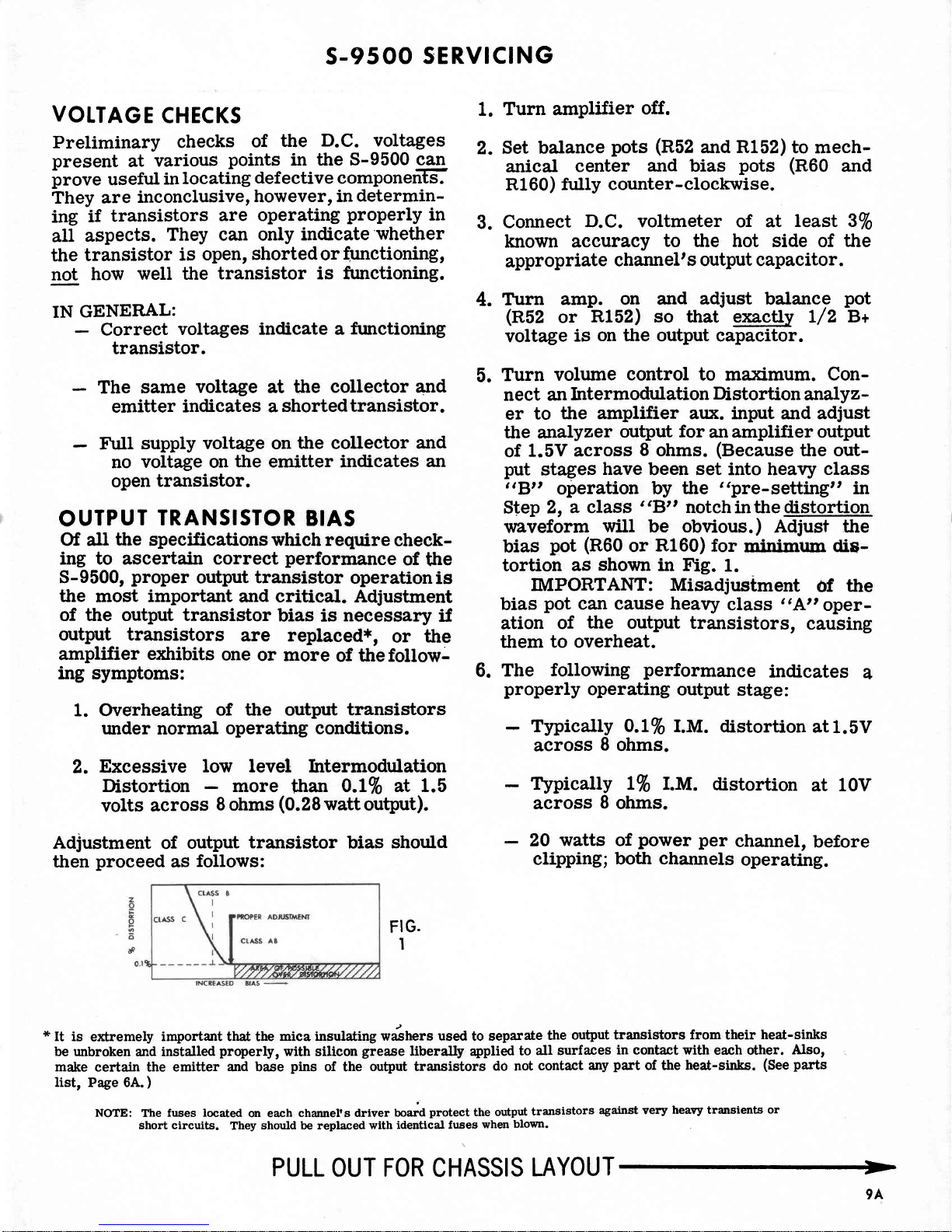
Adjustment
of
output
transistor bias should
then
proceed
as
follows:
FI
G.
I
*
It
is extremely important
that
the
mica insulating rih"", used to separate
the
output
transistors from their
heat-s
be unbroken
and instatled
properly,
with silicon
grease
liberally
applied
to
all
surfaces
in
contact
with
each other.
A
make
certain the emitter
and bas-e
pins
of the
output transistors
do not
contact
any
part
of the
heat-sinks.
(See
p
list,
Page 6A.
)
NOTE: The
fuses located
on each
channels driver
board
protect
the output
transistors
against very
heavy transients
or
short circuits.
They
should be replaced
with
identlcal fuses
when
blown
1.
2.
Turn amplifier
off.
Set balance
pots
(R52
and
R152)
to mech-
anical
center
and
bias
pots
(R60
and
Rl
60)
ftrlly
counter-
cloclwise.
Conneet
D.C. voltmeter
of at
least SVo
known accuracy
to
the hot side of
the
appropriate
channel's
output capacitor.
Turn
amp.
on and adjust balance
pot
(R52
or
R152)
so that exaetly t/2
B+
voltage
is
on the
output capacitor.
Turn
volume
eontrol to maximum. Con-
nect an
Intermodulation
Distortion
analyz-
er
to
the amplifier alx. input
and
adjust
the analyzer
output
for
an amplifier
output
of
1.5V
across
8
ohms.
(Because
the out-
put
stages
have
been set into healy class
3'B."
oleration
by
the
"pre-setting"
in
Step 2,
L elass
'
eB"
notch in the distortion
waveform
will
be obvious.
)
Adjust the
bias
pot
(R60
or
R160)
for
rninimum
dis-
tortion
as
shown
in Fig.
1.
IMPORTANT:
Misadjustment
Of
the
bias
pot
can cause heavy
class
3'A,,
oper-
ation
of
the
output transistors,
causing
them
to overheat.
The
following
performance
indicates
4
properly
operating
output
stage:
Typically
O.LVo
I.M.
distortion
at 1.5V
across
8
0hms.
Tlpically
LVo
I.M.
distortion
at 10V
across
8
0hms.
20
watts
of
power
per
channel,
before
clipping;
both channels
operating.
3.
4.
5.
6.
PULL
OUT
FOR
CHASSIS
LAYOUT
9A
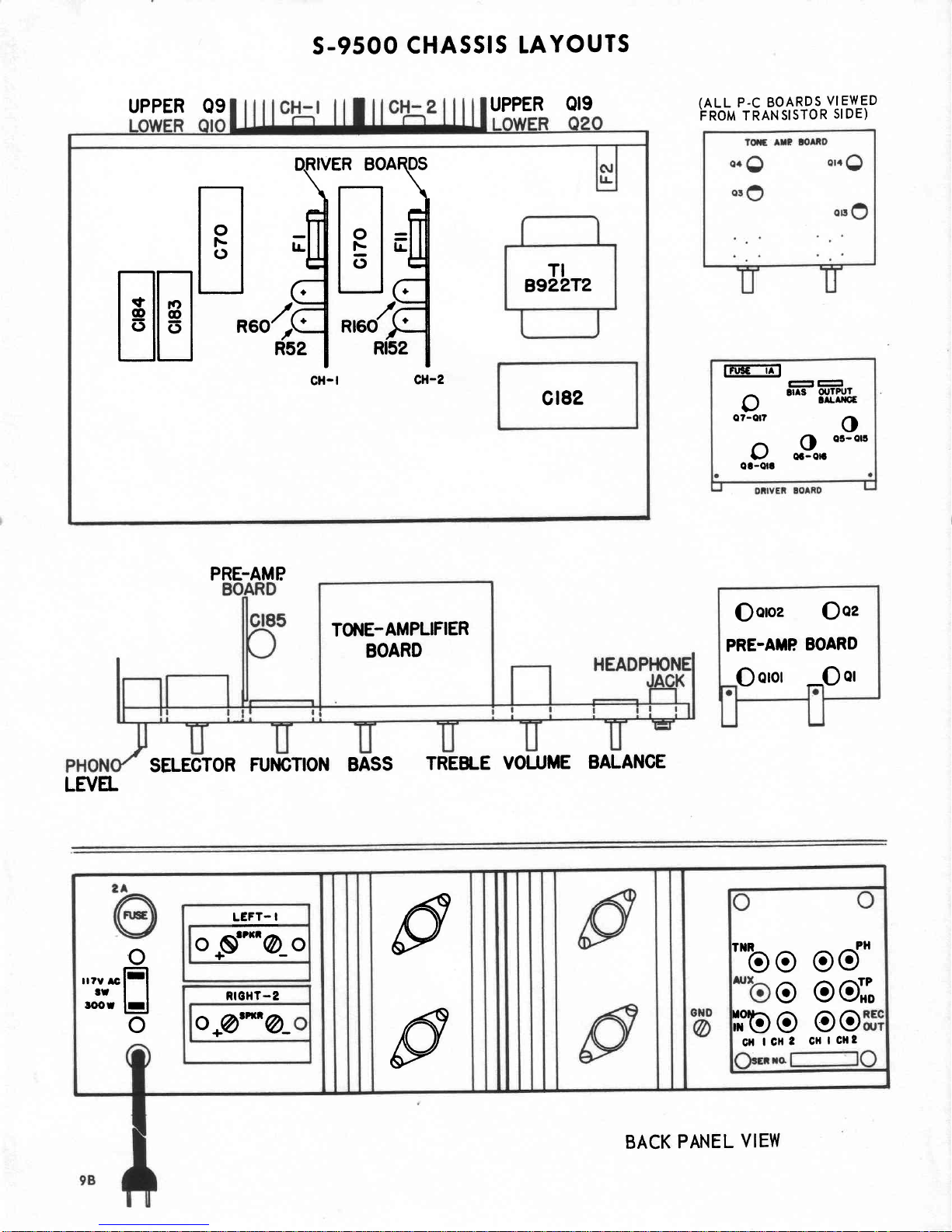
s-9500
cHASSlS LAYOUTS
UPPER Q9
UPPER
QI9
PRE-AMP
SELECTOR
FUI{GTION
BASS
TREBLE
VOLUME
BALANCE
(ALL
P.C BOARDS
VIEWED
Fnom rRANslsroR
slDE)
TI
B922T2
fidfi
E=,..,fi
R52
|
Rl52
I
cH-l
cH-z
,-,,-,[{
EEL-R6O
Gt82
rFGE-1in
-
-
,1
tl^s
9'
o7-or?
OIJTPT'I
!rLrl|cE
o
oc-or5
oB""
oa-ort
Qoroz
Ooz
PRE-AMP
BOARD
O
oror
-O
ot
TO]IIE-AMPLIFIER
BOARD
LE1/EL
@
p
o
,,r,
*lEl
trll
roof
lrl
o
LEFT-
I
.ttrl ^
o
Js""@_o
RICHT-2
o*@"n@_
'*bo
od'
o
oor,
iL"lOg
OO
clt
lcll
2 CHlcHt
BACK
PANEL
VIEW
 Loading...