

Page 1

XG-V10WE
AN-SD1E/S422E
SERVICE MANUAL
SERVICE-ANLEITUNG
S00J4XG-V10WE
LCD PROJECTOR
LCD PROJEKTOR
XG-V10WE
MODEL
AN-SD1E
MODELL
In the interests of user-safety (Required by safety regulations in some countries) the set should be restored
to its original condition and only parts identical to those specified should be used.
Im lnteresse der Benutzersicherheit (erforderliche Sicherheitsregeln in einigen Ländern) muß das Gerät in seinen
Originalzustand gebracht werden. Außerdem dürfen für die spezifizierten Bauteile nur identische Teile verwendet
werden.
AN-S422E
SHARP CORPORATION
1
Page 2

XG-V10WE
AN-SD1E/S422E
• SPECIFICATIONS ............................................. 3
• NOTE TO SERVICE PERSONNEL ................... 4
• OPERATION MANUAL ...................................... 6
• REMOVING OF MAJOR PARTS ..................... 14
• RESETTING THE TOT AL LAMP TIMER ......... 19
• THE OPTICAL UNIT OUTLINE........................ 20
• CONVERGENCE AND
FOCUS ADJUSTMENT .................................. 21
• ELECTRICAL ADJUSTMENT.......................... 27
• ADJUSTING THE PC INTERFACE ................. 35
• TROUBLE SHOOTING TABLE ........................ 39
• CHASSIS LAYOUT .........................................118
• BLOCK DIAGRAM ......................................... 120
CONTENTS
Page Page
• OVERALL WIRING DIAGRAM ...................... 122
• DESCRIPTION OF SCHEMATIC DIAGRAM . 124
• WAVEFORMS ................................................ 125
• SCHEMATIC DIAGRAM ................................ 126
• PRINTED WIRING BOARD ASSEMBLIES ... 184
• PARTS LIST
Ë
ELECTRICAL PARTS............................... 197
Ë
CABINET AND MECHANICAL PARTS .... 231
Ë
ACCESSORIES PARTS ........................... 236
Ë
PACKING PARTS..................................... 236
• PACKING OF THE SET ................................. 237
• OPTIONAL BOARDS..................................... 238
Seite Seite
• TECHNISCHE DATEN..................................... 60
• HINWEISE FÜR DAS
WARTUNGSPERSONAL................................. 61
• BEDIENUNGSANLEITUNG............................. 63
• ENTFERNEN DER HAUPTTEILE ................... 71
• RÜCKSTELLEN DES LAMPEN-BETRIEBS-
ZEITZÄHLERS................................................. 76
• ÜBERSICHT DER OPTIKEINHEIT.................. 77
• EINSTELLUNG VON KONVERGENZ UND
BRENNPUNKT ................................................ 78
• ELEKTRISCHE EINSTELLUNG ...................... 84
• EINSTELLUNG DER PC-PLATINE.................. 92
• FEHLERSUCHTABELLE ................................. 96
• CHASSIS-ANORDNUNG ...............................118
INHAL T
• BLOCKSCHALTBILD ..................................... 120
• GESAMTSCHALTPLAN................................. 122
• BESCHREIBUNG DES SCHEMATISCHEN
• WELLENFORMEN......................................... 125
• SCHEMATISCHER SCHALTPLAN................ 126
• LEITERPLATTENEINHEITEN ....................... 184
• ERSATZTEILLISTE
• VERPACKEN DES GERÄTS ......................... 237
• WAHLWEISE PLATINE.................................. 238
SCHALTPLANS ............................................. 124
Ë
ELEKTRISCHE BAUTEILE ...................... 197
Ë
CEHÄUSE UND MECHANISCHE
BAUTEILE ................................................ 231
Ë
ZUBEHÖRTEILE...................................... 236
Ë
VERPACKUNGSTEILE ............................ 236
2
Page 3

Specifications
XG-V10WE
AN-SD1E/S422E
Product type
Model
Video system
Display method
LCD panel
Projection lamp
Contrast ratio
Video input signal
S-video input signal
Component input signal
Horizontal resolution
RGB input signal
Pixel clock
Vertical frequency
Horizontal frequency
Computer contr ol signal
Speaker system
Rated voltage
Input current
Rated frequency
Power consumption
Power dissipation
Operating temperature
Storage temperature
Cabinet
I/R carrier frequency
Laser pointer of remote control
Dimensions (approx.)
Weight (appr ox.)
Supplied accessories
Replacement parts
LCD Projector
XG-V10WE
PAL/PAL 60/PAL-M/PAL-N/SECAM/NTSC 3.58/NTSC 4.43
DTV 480i/480P/720P/1080i
LCD panel ✕ 3, RGB optical shutter method
Panel size: 46 mm (1.8") (28.7 [H] ✕ 35.8 [W] mm)
Display method: Translucent TN liquid crystal panel
Drive method: TFT (Thin Film Transistor) Active Matrix panel
No. of dots: 1,310,720 dots (1,280 [H] ✕ 1,024 [V])
200 W UHP lamp ✕ 2
400:1
BNC Connector: VIDEO (INPUT 4, 5), composite video, 1.0 Vp-p, sync negative, 75 Ω
terminated
RCA Connector: AUDIO (INPUT 4, 5), 0.5 Vrms more than 22 kΩ (stereo)
4-pin Mini DIN connector (INPUT 4, 5)
Y (luminance signal): 1.0 Vp-p, sync negative, 75 Ω terminated
C (chrominance signal): Burst 0.286 Vp-p, 75 Ω terminated
BNC Connector (INPUT 2, 4, 5)
Y: 1.0 Vp-p, sync negative, 75 Ω terminated
B
: 0.7 Vp-p, 75 Ω terminated
P
R
: 0.7 Vp-p, 75 Ω terminated
P
620 TV lines (video input), 720 TV lines (DTV 720P input, Dot by Dot)
PIN MINI
D-
15-
SUB CONNECTOR
RGB separate/composite sync/sync on gr een type analog input: 0
(INPUT 1), 5 BNC
CONNECTOR
(INPUT 2):
0.7 Vp-p, positive,
terminated
CONNECTOR
DVI
ORIZONTAL SYNC. SIGNAL
H
ERTICAL SYNC. SIGNAL
V
230 MHz
12
200 Hz
43
126 kHz
15
9-pin D-sub connector (RS-232C Input Port/Output Port)
5 ✕ 8 cm (1
AC 110
(29-
PIN
) (INPUT 3), RGB (DIGITAL), 250 1,000 mV, 50 Ω
: Same as above
31
32
" ✕ 3
120/220 240 V
: TTL level (positive/negative) or composite sync (Apple only)
5
32
") oval ✕ 2, 3 W + 3 W (stereo)
6.2 A/3.1 A
50/60 Hz
575 W
< 2,100 BTU/hour
C to + 40 C
++5
20
C to + 60 C
Plastic
38 kHz
Wave length: 650 nm / Max. output: 1 mW / Class II Laser Product
444.2 ✕ 196.2 ✕ 621.3 mm (W ✕ H ✕ D) (main body only)
530.1 ✕ 221.9 ✕ 643.2 mm (W ✕ H ✕ D) (including standar d lens, terminal cover,
adjustment feet and projecting par ts)
18.9 kg (main body only)
Remote control, Two AA size batteries, Power cord (1.8 m), RGB cable (3 m), PS/2 mouse
control cable (1 m), USB mouse control cable (1 m), Remote mouse receiver, Extra air
filter, Terminal cover, CD-ROM, LCD projector operation manual, LCD pr ojector quick
references, Sharp Advanced Presentation Software operation manual
Lamp unit (Lamp/cage module) (BQC-XGV10WU/1), Remote control (RRMCG1565CESA),
AA size batteries, Power cord, RGB cable (QCNW-5304CEZZ), PS/2 mouse control cable
(QCNW-5113CEZZ), USB mouse control cable (QCNW -5680CEZZ), Remote mouse
receiver (RUNTK0673CEZZ), Air filter (PFILD0110CEZZ), Terminal cover
(CCOVA1789CE01), CD-ROM (UDSKA0027CEN1), LCD projector operation manual (TINS6975CEZZ), LCD projector quick references (TINS-6981CEZZ, TINS-6982CEZZ, TINS6983CEZZ), Sharp Advanced Presentation Software operation manual (TINS-6993CEZZ)
This SHARP projector uses LCD (Liquid Crystal Display) panels. These
very sophisticated panels contain 1,310,720 pixels ( ✕ RGB) TFTs
(Thin Film Transistors). As with any high technology electr onic
equipment such as lar ge scr een TVs, video systems and video
cameras, there are certain acceptable tolerances that the equipment
must conform to.
Specifications are subject to change without notice.
This unit has some inactive TFTs within acceptable tolerances which
may result in illuminated or inactive dots on the pictur e screen. This
will not affect the picture quality or the life expectancy of the unit.
3
Page 4

XG-V10WE
5
4
AN-SD1E/S422E
NOTE TO SERVICE
PERSONNEL
UV-RADIATION PRECAUTION
The light source, UHP lamp, in the LCD projector
emits small amounts of UV-Radiation.
A VOID DIRECT EYE AND SKIN EXPOSURE.
To ensure safety please adhere to the following:
1. Be sure to wear sun-glasses when servicing the
projector with the lamp
turned “on” and the top
enclosure removed.
2. Do not operate the lamp outside of the lamp housing.
234567890123456789012345678901212345678901234
UV-RADIATION PRECAUTION (Continued)
23456789012345678901234567890121234567890123
Lamp Replacement
Note:
Since the lamp reaches a very high temperature
during units operation replacement of the lamp
should be done at least one hour after the power
has been turned off. (to allow the lamp to cool off.)
Installing the new lamp, make sure not to touch the
lamp (bulb) replace the lamp by holding its reflector
2.
[Use original replacement only.]
Lamp
1
Reflector
2
DANGER ! –– Never turn the power on without the
lamp to avoid electric-shock or damage of the
devices since the stabilizer generates high voltages
at its start.
3. Do not operate for more than 2 hours with the
enclosure removed.
UV-Radiation and Medium Pressure
Lamp Precautions
1. Be sure to disconnect the AC plug when replacing
the lamp.
2. Allow one hour for the unit to cool down before
servicing.
3. Replace only with same type lamp. Type
CLMPF0064DE01/02 or BQC-XGV10WU/1 rated
100V/200W.
4. The lamp emits small amounts of UV-Radiation, avoid
direct-eye contact.
5. The medium pressure lamp involves a risk of
explosion. Be sure to follow installation instructions
described below and handle the lamp with care.
Since small amounts of UV-radiation are emitted from
an opening between the exhaust fans, it is recommended to place the cap of the optional lens on the
opening during servicing to avoid eye and skin ex-
posure (Fig. 1).
Note: Please obtain a lens cap before servicing a
model XG-V10WE that is received without
one.
LENS CAP
Figure 1.
4
Page 5
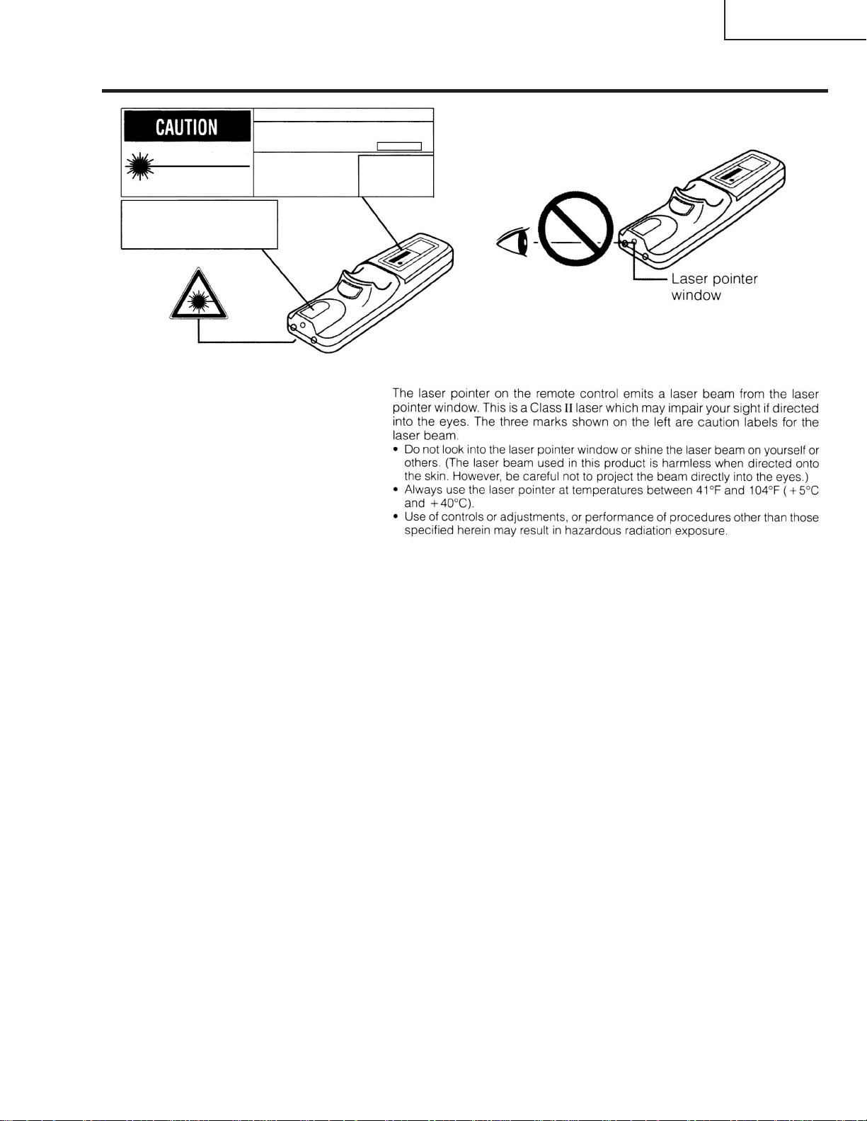
Cautions Concerning the Laser Pointer
"COMPLIES WITH 21 CFR SUBCHAPTER J"
SHARP ELECTRONICS CORPORATION
SHARP PLAZA, MAHWAH, NEW JERSEY 07430
TEL : 1-800-BE-SHARP
REMOTE CONTROL
MODEL NO. : RRMCG1564CESA
DC3V(1.5VX2PCS.)
MADE IN CHINA
FABRIQUÉ AU CHINE
LASER RADIATIONDO NOT STARE INTO BEAM
WAVE LENGTH : 650nm
MAX. OUTPUT : 1mW
CLASS II LASER PRODUCT
AVOID EXPOSURE-
LASER
RADIATION IS EMITTED
FROM THIS APERTURE.
U.S.A. ONLY
XG-V10WE
AN-SD1E/S422E
5
Page 6

XG-V10WE
AN-SD1E/S422E
Location of Controls
Projector
Front and Top View
MUTE button
POWER buttons (ON/OFF)
LENS button
ENTER button
INPUT 1, 2, 3 button
FREEZE button
ENLARGE button
UNDO button
VOLUME buttons (
MENU button
ADJUSTMENT buttons
(]/[/< /> )
INPUT 4, 5, 6 button
AUTO SYNC button
RESIZE button
GAMMA button
+ —
/)
Remote control sensor
Lens (sold separately)
Air filter (Intake vent)
Carrying handle
Adjuster
POWER indicator
LAMP 1 REPLACEMENT indicator
LAMP 2 REPLACEMENT indicator
TEMPERATURE WARNING indicator
6
Page 7
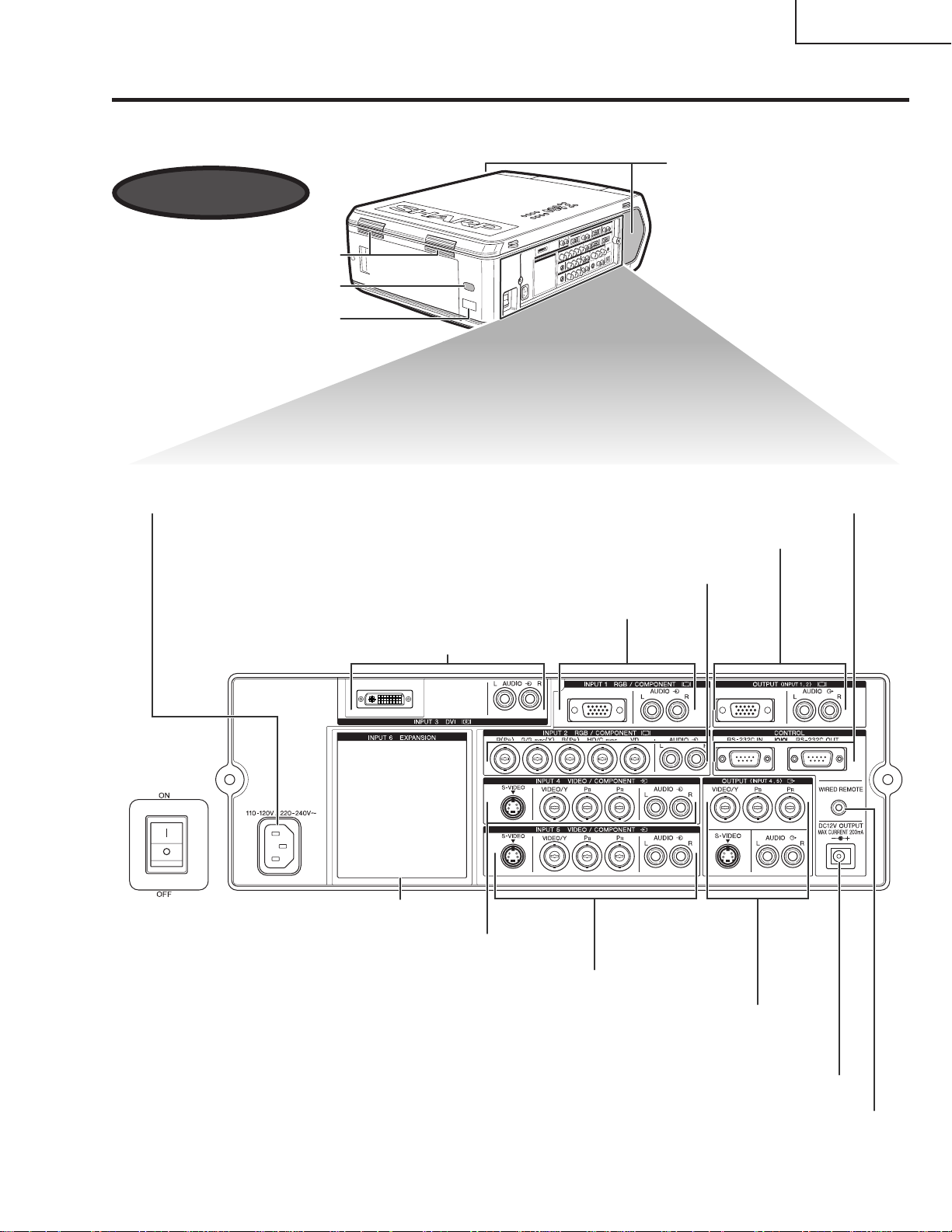
Projector
Side and Rear View
Exhaust vent
Remote control sensor
LED display (ID No.)
XG-V10WE
AN-SD1E/S422E
Speakers
AC socket
RS-232C INPUT port
RS-232C OUTPUT port
OUTPUT port (15-pin Mini D-sub) for INPUT 1, 2/
AUDIO OUTPUT terminals for INPUT 1, 2
INPUT 2 terminals/AUDIO INPUT 2 terminals
INPUT 1 port (15-pin Mini D-sub)/
AUDIO INPUT 1 terminals
INPUT 3 port (DVI)/
AUDIO INPUT 3 terminals
INPUT 6 EXPANSION board
S-VIDEO INPUT 4 terminal (4-pin Mini DIN)/
INPUT 4 terminals/AUDIO INPUT 4 terminals
MAIN POWER switch
S-VIDEO INPUT 5 terminal (4-pin Mini DIN)/
INPUT 5 terminals/AUDIO INPUT 5 terminals
OUTPUT terminals for INPUT 4, 5/
S-VIDEO OUTPUT terminal for INPUT 4, 5 (4-pin Mini DIN)/
AUDIO OUTPUT terminals for INPUT 4, 5
DC 12V OUTPUT
WIRED REMOTE control input terminal
7
Page 8

XG-V10WE
AN-SD1E/S422E
Operating the Wireless Mouse Remote Control
Remote Control
Front View
MUTE button
POWER buttons
LENS/BLACK
SCREEN button
RIGHT-CLICK/
ENTER button
FREEZE button
ADJUSTMENT
(ON/OFF)
MOUSE/
switch
1.2.3 4.5.6
VOLUME buttons
(+/—)
LASER POINTER/
MENU button
MOUSE/
ADJUSTMENT
buttons (]/[ /</> )
INPUT 4, 5, 6 buttonINPUT 1, 2, 3 button
AUTO SYNC button
RESIZE buttonENLARGE button
GAMMA buttonTOOLS button
BACKLIGHT button
Top View
Remote control
signal transmitter
Laser
pointer
window
Rear View
LEFT-CLICK/
UNDO
button
Bottom View
Bottom View
Wired remote control
input
Inserting the batteries
Press in on the arrow
13
mark and slide in the
direction of the arrow to
remove the battery cover.
Battery
cover
Insert two AA size
2
batteries, making sure
the polarities match the
+ and – marks inside
the battery compartment.
Battery
compartment
Insert the side tabs of
the battery cover into the
slots and press the
cover in until it is
properly seated.
Battery
cover
8
Page 9

Using the Remote Control as aWireless Mouse
XG-V10WE
AN-SD1E/S422E
The remote control has the following three functions:
¥ Projector control
MOUSE/ADJUSTMENT switch
(Remote control)
¥ Wireless mouse
¥ Laser pointer
MOUSE
ADJ.
Wireless mouse/
Laser pointer
MOUSE
ADJ.
Projector control
Remote Control/Mouse Receiver Positioning
¥ The remote control can be used to control the projector within the ranges shown below.
¥ The remote mouse receiver can be used with the remote control to control the mouse functions of a connected
computer within the ranges shown below.
¥ The signal from the remote control can be reflected off a screen for easy operation. However, the effective distance of the
signal may differ due to the screen material.
Controling the Projector
Remote Control
30ß
7 m
30ß
45ß
Using the Wireless Mouse
Remote Control
30ß
45ß
30ß
Remote Control
30ß
120ß
4 m
Remote
mouse
receiver
9
Page 10

XG-V10WE
AN-SD1E/S422E
Use as a Wireless Mouse
Be sure the supplied remote mouse receiver is connected to your computer.
Slide the MOUSE/ADJUSTMENT switch to MOUSE.
MOUSE mode buttons
BLACK SCREEN
MOUSE
LASER
POINTER
LEFT-CLICK
RIGHT-CLICK
1.2.3 4.5.6
MOUSE/
ADJUSTMENT
MOUSE
ADJ.
switch
Conference Series
• For one-button mouse systems, use either the LEFT-CLICK or RIGHT-CLICK button.
• Press BACKLIGHT to turn on the backlights of the operation buttons for about five seconds.
Button name
LASER POINTER/MENU
BLACK SCREEN/LENS
RIGHT-CLICK/ENTER
MOUSE/ADJUSTMENT
LEFT-CLICK/UNDO
POWER ON/OFF
VOLUME +/–
MUTE
Position of MOUSE/ADJUSTMENT switch
LASER POINTER (GREEN)
BLACK SCREEN (GREEN)
RIGHT-CLICK (GREEN)
MOUSE (NOT LIT)
ON (NOT LIT)
MOUSE
ADJ.
MENU (RED)
LENS (RED)
ENTER (RED)
ADJUSTMENT (NOT LIT)
UNDO (NOT LIT)
ON (RED)
Button name
INPUT 1, 2, 3
INPUT 4, 5, 6
FREEZE
AUTO SYNC
ENLARGE
RESIZE
TOOLS
GAMMA
Position of MOUSE/ADJUSTMENT switch
ADJ. MOUSE
ON (RED)
10
Page 11

XG-V10WE
AN-SD1E/S422E
Use as a Laser Pointer
Slide the MOUSE/ADJUSTMENT switch to MOUSE, and press LASER POINTER ( ) to activate
the laser pointer.
LASER
POINTER
1.2.3 4.5.6
MOUSE
MOUSE/ADJUSTMENT
ADJ.
switch
Conference Series
• When the button is released, the light automatically goes off.
• For safety reasons, the laser pointer automatically goes off after 1 minute of continuous use. To turn it on, release LASER
POINTER ( ) and press again.
Wired Remote Control
When the remote control cannot be used due to the range
or positioning of the projector (rear projection, etc.), connect
3.5 mm stereo minijack cable
(sold separately)
a 3.5 mm stereo minijack cable (sold separately) from the
wired remote control input on the bottom of the remote
control to the WIRED REMOTE control input terminal on the
side of the projector.
• The laser pointer and wireless mouse functions can still be
operated wthe wired remote control.
11
Page 12

XG-V10WE
AN-SD1E/S422E
Connection Pin Assignments
INPUT 1 RGB and OUTPUT (INPUT 1, 2) Signal Input Ports:15-pin Mini D-sub female connector
5
10
15
1
6
11
RGB Input
Analog
1. Video input (red)
2. Video input
(green/sync on green)
3. Video input (blue)
4. Reserve input 1
5. Composite sync
6.Earth (red)
7.Earth (green/sync on gr
Component Input
Analog
1. P
R
(CR)
2. Y
3. P
B
(CB)
4. Not connected
5.Not connected
6.Earth (P
R
)
7.Earth (Y)
8.Earth (P
B
)
8.Earth (blue)
9.Not connected
10. GND
11. GND
12. Bi-directional data
13. Horizontal sync signal
14. Vertical sync signal
15.Data clock
9.Not connected
10. Not connected
11. Not connected
12. Not connected
13. Not connected
14. Not connected
15.Not connected
RS-232C Port: 9-pin D-sub male connector of the DIN-D-sub RS-232C cable
15
69
Pin No. Signal Name I/O Reference
1 CD Not connected
2 RD Receive Data Input Connected to internal circuit
3 SD Send Data Output Connected to internal circuit
4 ER Not connected
5 SG Signal Ground Connected to internal circuit
6 DR Data Set Ready Output Not connected
7 RS Request to Send Output Connected to internal circuit
8 CS Clear to Send Input Connected to internal circuit
9 CI Not connected
DVI Port: 29-pin
Pin No. Name
1 T.M.D.S. Data 2—
2 T.M.D.S. Data 2+
C1 C2
91
16
8
C32417
C5
¥*1 Return for +5 V, Hsync. and Vsync.
2
¥*
Analog R, G and B return
3
These pins are not used on this equipment.
¥*
C4
3 T.M.D.S. Data 2/4 Shield
4 T.M.D.S. Data 4—*
5 T.M.D.S. Data 4+ *
6 DDC Clock
7 DDC Data
8 Analog Vertical Sync
9 T.M.D.S. Data 1—
10 T.M.D.S. Data 1+
11 T.M.D.S. Data 1/3 Shield
12 T.M.D.S. Data 3—*
13 T.M.D.S. Data 3+ *
14 +5 V Power
15 Ground*
1
16 Hot Plug Detect
17 T.M.D.S. Data 0—
18 T.M.D.S. Data 0—
19 T.M.D.S. Data 0/5 Shield
20 T.M.D.S. Data 5—*
21 T.M.D.S. Data 5+ *
22 T.M.D.S. Clock Shield
23 T.M.D.S. Clock+
24 T.M.D.S. Clock—
C1 Analog Red
C2 Analog Green
C3 Analog Blue
C4 Analog Horizontal sync
C5 Analog Ground*
3
3
3
3
3
3
2
12
Page 13

Dimensions
414.5
221.85
74.5
25.65 81.85 621.3
444.2
3.9
42
376
Rear View
Top View
Side View
Side View
Front View
Bottom View
Units: mm
XG-V10WE
AN-SD1E/S422E
13
Page 14

XG-V10WE
AN-SD1E/S422E
REMOVING OF MAJOR PARTS
1.Removing the intake cover, intake filter and lamp unit.
1-1. Detach the intake cover.
1-2. Detach the intake filter.
1-3. Loosen the lock screw from the lamp cover and slide the lamp cover off position.
1-4. Remove the three lock screws each from the lamp units 1 and 2, and detach these units.
Intake cover
1-3
Lamp cover
Lamp unit 1
1-4
1-4
Lamp unit 2
1-2
1-1
Intake filter
14
Page 15
XG-V10WE
AN-SD1E/S422E
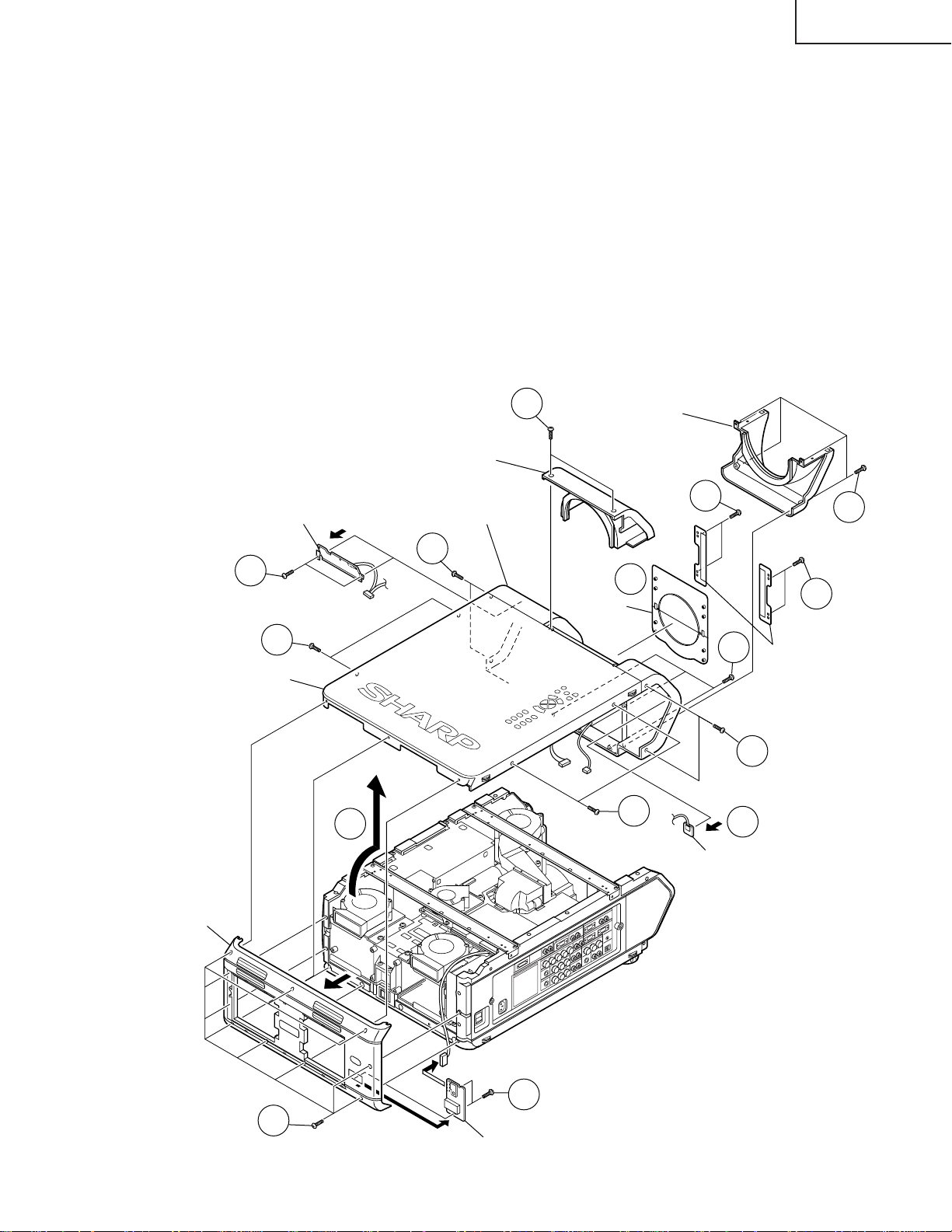
2.Removing the front, top and rear panels.
2-1. Remove the ten lock screws from the rear panel. Disconnect the connector (RD) of the remote control receiver
PWB unit 2. Then detach the rear panel.
2-2. Remove the two lock screws from the remote control receiver PWB unit 2. Detach the remote control receiver
PWB unit 2.
2-3. Remove the two lock screws from the lens cover (top) and detach the lens cover (top).
2-4. Remove the four lock screws from the lens cover (bottom) and detach the lens cover (bottom).
2-5. Remove the four lock screws from the shutter holder and detach the shutter holder.
2-6. Take out the shutter.
2-7. Remove the seven lock screws from the front panel.(Long size 2, Short size 5)
2-8. Remove the four lock screws from the top panel.
2-9. Slowly lift the back of the top panel. Disconnect the following connectors: connector (KY) of the operation
unit, connector (L) of the leaf switch, and connector (RE) of the LED PWB unit and remote control receiver
PWB unit 1. Lift and detach both the front and top panels.
2-10. Remove the two lock screws from the LED PWB unit. Detach the LED PWB unit.
2-11. Open the hooks of the remote control receiver PWB unit 1 and take out the remote control receiver PWB 1.
LED PWB unit
2-10
2-8
Top panel
Lens cover (top)
(RE)
2-9
Front panel
2-7
2-3
Lens cover (bottom)
2-6
Shutter
(KY)
(L)
2-8
2-5
2-7
2-11
2-4
2-5
Shutter holder
2-7
Rear panel
Remote control
receiver PWB unit 1
(RD)
2-2
2-1
Remote control receiver PWB unit 2
15
Page 16

XG-V10WE
AN-SD1E/S422E
3.Removing the reinforcing angles and intake fan duct assembly.
3-1. Remove the four lock screws from the front reinforcing angle and detach this angle.
3-2. Remove the four lock screws from the rear reinforcing angle and detach this angle.
3-3. Remove the five lock screws from the intake fan duct assembly and detach this assembly.
3-4. Remove the two lock screws from the intake cover and detach this cover.
3-1
Front reinforcing angle
3-1
Rear reinforcing angle
3-2
3-2
Intake cover
3-2
3-4
3-3
3-3
Intake fan duct assembly
3-3
16
Page 17

XG-V10WE
AN-SD1E/S422E
4.Removing the PWBs
4-1. Remove the two lock screws from the DVI connector.
4-2. Remove the five lock screws from the PC I/F PWB. Lift this PWB off the output PWB unit.
4-3. Remove the four lock screws from the cooling fan. Remove the lock screw from the output sub-PWB unit and
disconnect the connectors. Lift the cooling fan and the output sub-PWB unit off the output PWB unit.
4-4. Disconnect the connectors from the output PWB unit.
4-5. Remove the four stud bolts and eight lock screws from the output PWB unit. Lift and detach the output PWB
unit.
4-6. Disconnect the connector (SP) of the signal PWB unit.
4-7. Remove the eight lock screws from the side terminal board.
4-8. Remove the lock screw from the terminal cover and detach the terminal cover.
4-9. Remove the three lock screws from the grounding plate behind the terminal cover and detach the grounding
plate.
4-10. Detach the terminal board from the left-side panel. Lift the input PWB unit and the signal PWB unit off position.
Output
(F6)
(F8)
(S8)
(F7)
(TP)
(S7)
(GP)
(RP)
(BP)
(F5)
(KY)
sub-PWB
unit
(S5)
FRONT
(AZ)
(AS)
(F1)
(RE)
(L)
Cooling fan
Output sub-PWB unit
4-3
4-5
4-2
PC I/F PWB unit
4-5
4-4
(TOP VIEW)
(F4)
(S4)
(S3)
(F3)
(F2)
(RD)
(LL)
(EC)
(RL) (D) (EA)
Output
PWB unit
Output PWB unit
` Note: When reassembling, fit
the projection of the
terminal PWB shield in
the positioning hole of the
left-side panel.
4-5
4-5
4-5
4-1
`
4-8
Signal PWB unit
Input PWB unit
4-6
4-10
Left-side panel
4-7
4-9
4-7
17
Page 18

XG-V10WE
AN-SD1E/S422E
5.Removing the power/ballast PWB unit assembly.
5-1. Remove the lock screw from the socket holder (with shorter lead) for the lamp unit 1. Slide sideway and
detach the holder.
5-2. Remove the lock screw from the socket holder (with longer lead) for the lamp unit 2. Slide sideway and
detach the holder.
5-3. Disconnect the connectors from the power/ballast PWB unit assembly.
5-4. Remove the six lock screws from the power/ballast PWB unit assembly. Lift and detach this assembly.
6.Removing the inlet PWB unit assembly.
6-1. Remove the three lock screws from the left-side panel at the inlet PWB unit assembly.
6-2. Disconnect the connectors from the inlet PWB unit assembly.
6-3. Remove the two lock screws from the bottom panel at the inlet PWB unit assembly. Lift and detach this
assembly.
7.Removing the optical mechanism unit.
7-1. Remove the five lock screws from the lamp fan assembly.
7-2. Remove the seven lock screws
from the optical mechanism unit.
Lift and detach this unit.
5-1
5-3
(BB)
5-4
(EA)
Power/ballast PWB
unit assembly
(PL)
5-3
(F7)
7-1
Lamp fan assembly
Bottom panel
7-1
5-2
(F6)
7-2
7-1
Optical mechanism unit
Left-side panel
(EC)
6-3
6-2
6-1
(PA)
Inlet PWB unit assembly
18
Page 19

XG-V10WE
AN-SD1E/S422E
Resetting the TOTAL LAMP TIMER
Resetting the counter
» Draw out the lamp to be replaced. Turn on the power and the absence of the lamp is detected. Now reset the total
hour counter.
Resetting procedure
Replacing one lamp Replacing both lamps
1 Draw out the relevant lamp only. Draw out both the lamps.
2 Turn on the main power.
3 Press POWER button to LCD projector on.
4
5 Turn off the main power. Fit a new lamp into position.
» With just one of the lamps drawn out, the optical mechanism may get unstable in temperature. To avoid this,
the projector comes in the reset mode.
» For two or more projectors, their counters cannot be reset at once using the remote controller. Press the
ENTER key for resetting.
» In the process mode, the historical information is also reset.
The LED indicator at the drawn-out lamp side starts flashing.
Press the ENTER key to reset the counter. The LED indicator goes out.
End
Maintenance Indicator
TEMPERATURE
WARNING indicator
LAMP REPLACEMENT indicator
(LAMP1, LAMP2)
POWER indicator
Condition
The internal
temperature is
abnormally high.
The lamp does
not light up.
The POWER
indicator flashes
in red when the
projector is on.
Problem
· Blocked air intake.
· Clogged air filter.
· Cooling fan breakdown.
· Internal circuit failure.
· Burnt-out lamp.
· Lamp circuit failure.
· The filter cover is open.
· The lens cover is missing.
Possible Solution
· Relocate the projector to an area with
proper ventilation.
· Clean the filter.
· Take the projector to your nearest Authorized Sharp Industrial LCD Products
Dealer or Service Center for repair.
· Carefully replace the lamp.
· Take the projector to your nearest Authorized Sharp Industrial LCD Products
Dealer or Service Center for repair.
· Securely install the filter cover.
· Remove the top lens cover
(CCOVA1785CE01) off the front panel.
19
Page 20

XG-V10WE
AN-SD1E/S422E
THE OPTICAL UNIT OUTLINE
Layout of the optical system
Note: Layout for positioning the optical system.
★2 Output polarizer R
★2 Output polarizer G
Dichroic coating
(R transmission)
Dichroic coating
(G transmission)
AL-deposited face
Marking
★M2
Dichroic coating
UV absorbing glass
PBS aperture
Fly-eye lens
R-LCD
M5
L2(R)
AL-coated mirror R
RED
B/G reflector
G-LCD
Projection Lens
L2(G)
G/R Reflector
★M3
Marking
L1
Cross dichroic prism
AL-coated mirror B
G03
B-DF
GREEN
G01
PBS
(polarization beam splitter)
Marking
AL-deposited face
Dicroic coating
(B transmission)
Relay lens 1
★2 Output polarizer B
B-LCD
Input polarizer B
Relay lens 3
M6
AL-deposited face
Relay lens 2
G02
BLUE
M4
AL-coated mirror B
UHP lamp
(Light source)
Marking
★ M2 and M3 mirrors have a coat-
ing wedge (for different film thickness). Set up these mirrors, with
their markings positioned as
shown above, so that their
coated faces and both sides be
in the correct directions.
Prism array
★2 See the assemble-illustration
for determing a direction of
the output polarizer.
20
UHP lamp
(Light source)
UV-IR filter
Page 21

XG-V10WE
AN-SD1E/S422E
CONVERGENCE AND FOCUS ADJUSTMENT
» Place the set in the ceiling-mounted position, open the maintenance door, and start the
convergence and focus adjustments. Make sure the settings are complete and then turn
on the power. For adjusting the image, use the remote controller. Take the following
adjustment procedures.
1. Focusing the projection lens
(A) Replacing all the 3 LCD panels
1. Before replacing all the 3 LCD panels, project an image on the screen and bring it into focus.
2. Replace the panels with new ones. But until the focus has been completely readjusted, be careful not to
change the distance between the set and the screen, nor to move the projection lens focus and zoom
rings.
If the focus is readjusted with a different positional relation, the relation between the projection distance
and the screen size is affected. In other words, a short-distance image (40 WIDE, for example) may get
out of the focus range, or a long-distance image (300 WIDE, for example) may come out of focus.
(B) Replacing 1 or 2 of the 3 LCD panels
1. In adjusting the focus after replacement of one or two LCD panels, project an image on the screen and turn
the projection lens focus ring to get the non-replaced LCD panel into focus.
2. But until the focus has been completely adjusted for the new LCD panels, be careful not to change the
distance between the set and the screen, nor to move the projection lens focus and zoom rings.
(If the distance has been changed or the projection lens readjusted, repeat the above steps 1 and 2.)
2. Adjusting the G-LCD panel
(A) Focus adjustment. (Make this adjustment on the white-only screen.)
1. Right-and-left focus adjustment (θY direction) .
Loosen the lock screws "b" and "c" and insert the eccentric screwdriver into the notch and hole "b". Turn
the screwdriver until the right and left halves on the screen get into focus.
First get the right and left halves in balance. Then improve the accuracy while making the adjustment 2
below.
2. Top-center-bottom focus adjustment (θX and Z directions).
Loosen the lock screws "a" and "c" and insert the eccentric screwdriver into the notch and hole "a" or "c".
Turn the screwdriver until the top, center and bottom on the screen get into focus. In adjusting this top-tobottom focus, temporarily tighten the lock screw "b" to fix the θY direction adjustment.
3. Repeat the above steps 1 and 2 to finely adjust the focus. Finally tighten up all the lock screws.
Notes :
1 Carefully proceed with the focus adjustment because the adjusting directions are correlated.
2 In adjusting the convergence and focus, do not move the projection lens zoom and focus rings until the end
of all the adjustments.
(B) Convergence adjustment
» The G-LCD panel has no convergence adjustment mechanism. Use this panel as convergence adjustment
reference.
3. B-LCD panel adjustment (the same for the R-LCD panel)
(A) Focus adjustment
» T ake the same procedure as for the G-LCD panel focus adjustment. Note that the adjustment range is small
in the Z direction. If the convergence is quite different between the B-LCD and G-LCD panels, roughly adjust
the convergence first and then the focus.
(B) Convergence adjustment
» Use a crosshatch pattern signal for this adjustment.
Make the adjustment just for the G-color and the relevant color.
(1) Loosen the convergence lock screw "d".
(2) With the G-LCD panel’s screen center as reference, adjust the B-LCD panel in the X, Y and θZ directions.
(3) Finally tighten up the convergence lock screw "d".
21
Page 22

XG-V10WE
AN-SD1E/S422E
Notes :
1 The eccentric cam is used for convergence adjustment. This means that the cam’s turning and the linear
movement are not always uniform.
2 This model is not equipped with the LCD image adjustment mechanism. This is because the dichroic prism
is used for image formation. When the LCD panels all get into the best focus, the images are almost
completely converged.
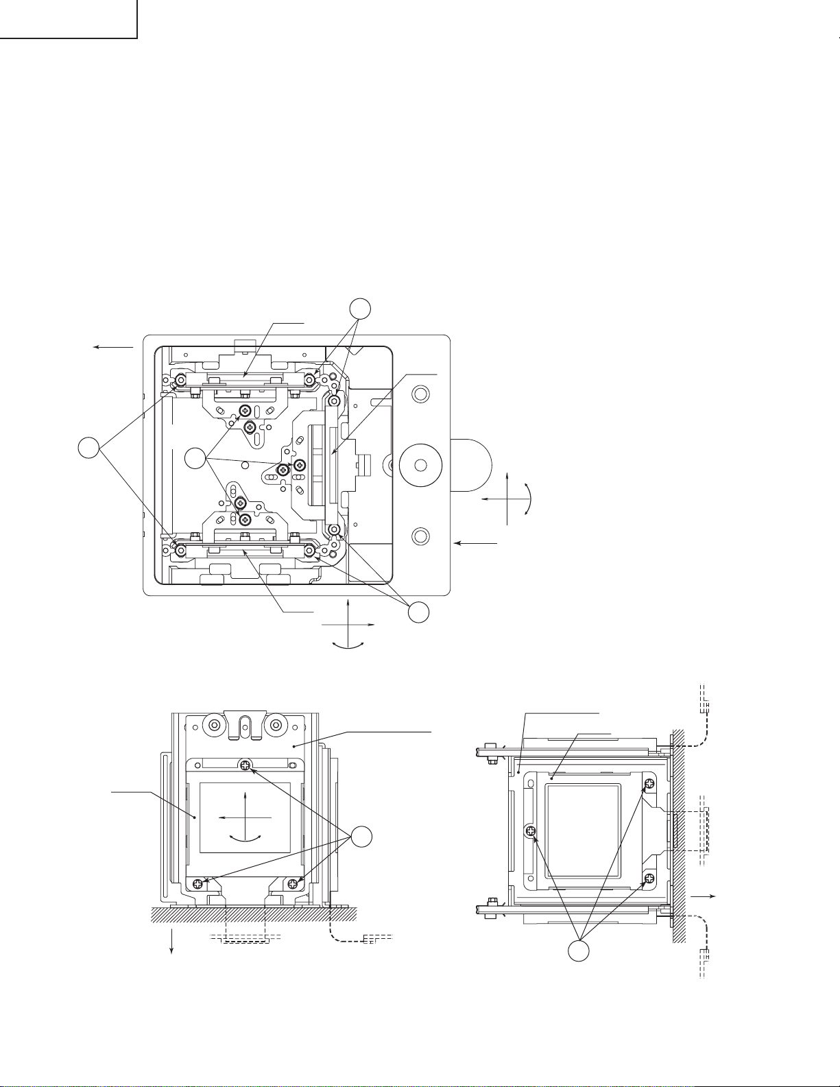
Convergence and Focus Adjustments Mechanism
BOTT OM VIEW SIDE VIEW
FRONT
Lock screw "a"
Notch and hole "a"
SIDE VIEW (from outside) SIDE VIEW (from inside)
R-LCD
B-LCD
Lock screw "c"
Notch and hole "c"
θ
X
G-LCD panel
mounting screws
G-LCD
Notch and hole "b"
Lock screw "b"
X
Y
Z
Notch and hole "c"
Z
θ
Y
Lock screw "c"
X
θ
Eccentric cam
Y
Z
TOP
G-LCD
G adjusting plate
RáB-LCD
TOP
Lock screw "d"
Y
X
θ
Z
(convergence
adjustment)
RáB-LCD panel
mounting screws
22
Page 23

Convergence and Focus Adjustments at a Glance
2
5
16
R2
50
CUT
Adjustment directions
Adjustment Direction Definition Direction of LCD panel
X direction LCD right and left
Convergence Y direction LCD top and bottom
θZ direction Rotation around Z axis LCD turning axis
Z direction LCD optical axis
Focus θX direction Rotation around X axis LCD top-to-bottom flapping
θY direction Rotation around Y axis LCD right-to-left flapping
Convergence and Focus Adjustment for the Optical Mechanism
XG-V10WE
AN-SD1E/S422E
Color Adjustment Direction
X direction ±0.8mm Eccentric cam Eccentric cam adjusting wrench d Hex wrench
Convergence Y direction ±0.8mm Eccentric cam Eccentric cam adjusting wrench d Hex wrench
R/B θZ direction ±1° Eccentric cam Eccentric cam adjusting wrench d Hex wrench
colors Z direction ±1.3mm
Focus θX direction ±1°
θY direction ±2.5°
Z direction ±0.4mm
G color Focus θX direction ±1° Same as for R and B colors
θY direction ±2.5°
Movement
Position Adjusting tool
Notch and hole "a" & "c"
Notch and hole "a" & "c"
Notch and hole "b" & "c"
Eccentric screwdriver a, c
Lock screw
a, c
b, c
Tightening tool
Phillips
screwdriver,
*Hex wrench
Focus Adjustments the Other Way
Lock screw Position Related direction
a Notch and hole "a" Z and θX directions
b Notch and hole "b" θY direction
c Notch and hole "c" Z, θX and θY directions
Convergence and Focus Adjusting and Tightening Tools
Tool Specific or General Tool code Configuration
Eccentric cam Specific 9DASPN-XGNV1U
adjusting wrench
80
Eccentric screwdriver Specific 9EQDRiVER-NV1A
100
Hex wrench General (redesigned) 9EQLNC-XGNV1U
Phillips screwdriver General — For M2.6 pan-head machine screw
*Hex wrench General —
23
Preferably use a 70 mm or longer
screwdriver (with a handle).
Page 24
XG-V10WE
AN-SD1E/S422E
Replacing the LCDs
Remove the top cover.
(1)Remove the six screws off the relay duct and disconnect the relay duct.
(2)Remove the two screws off the upper suction cover and detach this cover.
(3)Disconnect the LCD flat cable from the PWB connector.
(4)Place the set in the ceiling-mounted position and open the maintenance door.
(5)Remove the lock screws "b" and "c". Take out the LCD-equipped R/B adjusting board and G adjusting board.
(6)Detach the LCD panel from the adjusting board.
(7)Place a replacement LCD panel and take the above steps (1) thru (5) in the reverse order.
~ Keep in mind that the G LCD panel does not need convergence readjustment and that it has a small adjustable
range in the Z direction.
BOTT OM VIEW
Lock
R-LCD
FRONT
5
screws "c"
G-LCD
Lock
5
Lock
screws "c"
screws "b"
5
B-LCD
Z
X
θY
5
Lock
screws "c"
SIDE VIEW SIDE VIEW
R·B adjusting plate
R·B-LCD
Y
X
X
Z
`
G adjusting plate
θY
G-LCD
TOP
θZ
6
R·B-LCD panel
mounting screws
G-LCD panel
6
mounting screws
TOP
24
Page 25

XG-V10WE
AN-SD1E/S422E
1. Adjusting the mirror optical axis
The optical axis must be readjusted to correct possible eclipse that occurs with the R, G or B LCD panel.
This readjustment is usually required when an optical part in the optical mechanism has been replaced,
and may be needed when a LCD panel has been replaced.
1. Disconnect the LCD flat cable.
2. Get the lamp on. Be sure to start the cooling fan too.
(Eclipse with the R LCD panel: Screen edges appearing in cyan)
3. Loosen the lock screws of the M5 adjusting lever.
4. Watching the image on the screen, turn or slide the M5 adjusting lever until the eclipse disappears from the
screen. Now tighten up the lock screws.
(Eclipse with the G LCD panel: Screen edges appearing in magenta)
3. Loosen the lock screws of the M3 adjusting lever.
4. Watching the image on the screen, turn or slide the M3 adjusting lever until the eclipse disappears from the
screen. Now tighten up the lock screws.
(Eclipse with the B LCD panel: Screen edges appearing in yellow)
3. Loosen the lock screws of the M6 adjusting lever.
4. Watching the image on the screen, turn or slide the M6 adjusting lever until the eclipse disappears from the
screen. Now tighten up the lock screws.
2. Adjusting the orientation of polarizer
The contrast must be optimized when the polarizer or an optical mechanism part has been replaced.
1. Turn on the power.
2. If the background is blue, clear the screen and get it black.
3. Loosen the two lock screws of the polarizer (two for each plate).
4. Press the heads of the lock screws in the arrow directions until the onscreen contrast becomes best. Finally
tighten up the lock screws.
3. Adjusting the PBS
This adjustment may be required when the optical mechanism has been disassembled. Colors uneven
on the right and left halves onscreen can be corrected here. Usually there is no need to make this adjustment. It is enough to have the lamp adjusting groove in alignment.
1. Turn on the power.
2. Loosen the PBS lock screw.
3. Feed a white-only signal, or call the process mode and get the screen white only.
4. Put the eccentric screwdriver (9EQDRiVER-NV1A) in the PBS adjusting groove.
5. Watching the image on the screen, turn the eccentric screwdriver until the right-and-left colors onscreen
become most even. Finally tighten up the lock screw.
4. Adjusting the lamp optical axis
The lamp optical axis is optimized to obtain the best color evenness and brightness. Usually there is no
need to make this adjustment because the replacement lamp unit (BQC-XGV10WU/1) has been delivered
factory-adjusted.
1. Turn on the power.
2. Loosen the three lamp lock screws.
3. Feed a white-only signal, or call the process mode and get the screen white only.
4. Put the eccentric screwdriver (9EQDRiVER-NV1A) in the lamp adjusting groove.
5. Watching the image on the screen, turn the eccentric screwdriver until the right-and-left colors onscreen
become most even. Finally tighten up the lock screws.
25
Page 26

XG-V10WE
AN-SD1E/S422E
Mirror adjusting
lever lock screws
PBS lock screw
PBS adjusting groove
Lamp adjusting groove
4
1
M5 adjusting lever
R
2
G
M3 adjusting lever
4
1
M6 adjusting lever
Mirror adjusting
lever lock screws
B
1
Mirror adjusting lever
lock screws
Lamp adjusting groove
3
Lamp lock screws
Lamp lock screws
26
Page 27

XG-V10WE
AN-SD1E/S422E
ELECTRICAL ADJUSTMENT
Hook up a signal generator, or a DOSV or Mac personal computer to the projector in order to feed the
signals specified in the Adjusting conditions.
No. Adjusting point Adjusting conditions Adjusting procedure
1 EEPROM
initialization
1. Turn on the power (with the
lamp on) and warm up the
set for 15 minutes.
» Make the following settings.
Press S2601 to call the process mode. Execute
the S2 and S4 commands on the SSS menu. With
the S2 command, all but the PC boards will be
initialized. Do not execute the S1 command
because this will get the PC boards initialized. To
readjust the PC boards, refer to "Adjusting the PC
interface" on page 35.
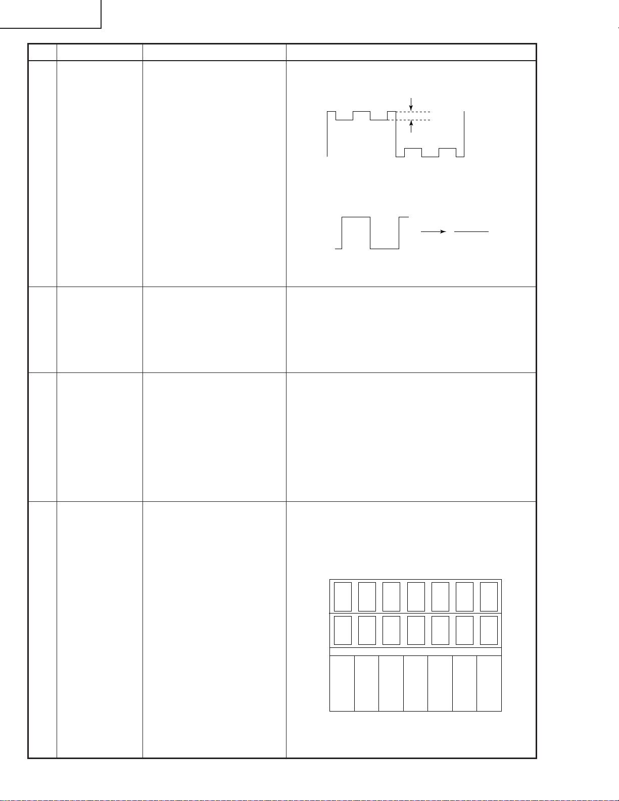
2 RGB drive
adjustment
3 RGB1 system
black level
signal amplitude
adjustment
1. Feed the 100% white sig-
nal.
2. Select the following group
and subjects.
Group : A/D
Subject : R-D (R)
G-D (G)
B-D (B)
1. Select the following group
and subjects.
Group : OUTPUT1
Subject : G1-BLK
G1-GAIN
For the R and B colours,
choose the following respective subjects.
R1-BLK and R1-GAIN for R
B1-BLK and B1-GAIN for B
2. Make sure the process adjustment colour bars are being displayed.
3. Connect the oscilloscope to
pin (3) (for G) of P1001.
4. Similarly connect the oscilloscope to the following for
the R and B colours.
Pin (1) of P1001 for R
Pin (5) of P1001 for B
» Using the set's control switch or the remote
controller's button, adjust the settings so that there
be some bit dropouts.
» Select G1-GAIN. Using the set's control switch or
the remote controller’s button, adjust the setting so
that the signal amplitude be 3.7 ± 0.05 Vp-p.
» Select G1-BLK. Using the set’s control switch or
the remote controller’s button, adjust the setting so
that the white to white level be 2.4 ± 0.05 Vp-p.
» Do the same for the R and B colours.
2.4Vp-p
3.7Vp-p
`The G1 settings affect all the R, G and B signals
at the same time. When the G1-BLK setting has
been changed, therefore, the R1-BLK and B1-BLK
settings are accordingly modified. Also with a
change in the G1-GAIN setting, the R1-GAIN and
B1-GAIN settings are accordingly modified. In
other words, adjust the G settings first and then
the R as well as B settings.
27
Page 28
XG-V10WE
AN-SD1E/S422E
No. Adjusting point Adjusting conditions Adjusting procedure
4 RGB2 system
black level
signal amplitude
adjustment
5 Sample hold
pulse phase
checking
1. Select the following group
and subjects.
Group : OUTPUT2
Subject : R2-GAIN
R2-BLK
For the G and B colours,
choose the following respective subjects.
G2-GAIN and G2-BLK for G
B2-GAIN and B2-BLK for B
2. Connect the oscilloscope to
pin (2) (for R) of P1001.
3. Similarly connect the oscilloscope to the following for
the G and B colours.
Pin (4) of P1001 for G
Pin (6) of P1001 for B
1. Feed the SXGA-mode, 75-
Hz black signal.
2. Select the following group
and subject.
Group : OUTPUT3
Subject : SH-PHASE
» Select R2-GAIN. Adjust the setting so that the
signal component has the minimum amplitude.
» Select R2-BLK. Adjust the setting so that the wave-
form becomes a straight horizontal line.
Adjusted to
» Using the set's control switch or the remote
controller’s button, make sure the characters
OUTPUT3 are not blurry with no ghost image on
the screen. If anything blurry or a ghost image
appears onscreen, readjust the setting in the
range of 7-9.
6 RGB
countervoltage
adjustment
7 RGB tone
reproduction
adjustment
1. Feed the SXGA-mode, 60-
Hz, countervoltage adjustment signal.
2. Select the following group
and subjects.
Group : OUTPUT3
Subject : RC (R)
GC (G)
BC (B)
1. Feed the Infocom
Grayscale & Colour
Pattern signal.
2. Select the following group
and subject.
Group : OUTPUT1
Subject : G1-BLK
» Using the set's control switch or the remote
controller’s button, adjust the setting so that the
flickering be minimum.
» If there is a difference between the center and
both sides on the screen, adjust the setting to get
both sides equal to each other.
» Make sure the grayscale, shown below, is visible
up to the tone 251 (white) as well as down to the
tone 8 (black).
» If the white tone is out of spec, finely adjust the
G1-BLK setting.
4
812
249 251
28
Page 29

No. Adjusting point Adjusting conditions Adjusting procedure
XG-V10WE
AN-SD1E/S422E
8 RGB white
balance adjustment
9 Video horizontal
center adjustment
DLY checking
10 Video picture
adjustment
1. Feed the 32-step grayscale
signal. (SXGA, 60 Hz)
2. Select the following group
and subjects.
Group : OUTPUT1
Subject : R1-BLK (R)
B1-BLK (B)
1. Feed the NTSC
monoscope pattern signal.
2. Group : VIDEO 2
Subject : N358-DLY (2)
N443-DLY (0)
PAL-DLY (0)
SECAM-DLY(0)
Make sure the settings are
as above.
3. Then select the following
group and subject.
Group : VIDEO1
Subject : NTSC-H
1. Feed the split colour bar
signal.
2. Select the following group
and subject.
Group : VIDEO1
Subject : PICTURE
3. Connect the oscilloscope
between pin (1) of P801
and GND.
» Adjust the R1-BLK and B1-BLK settings to get the
tone balance to optimum.
» Using the set's control switch or the remote con-
troller’s button, adjust the setting so that the
overscan be the same at right and left.
» Using the set’s control switch or the remote con-
troller’s button, adjust the setting so that the amplitude between the black and 100% white levels be
2.3 ± 0.02 Vp-p.
2.3Vp-p
11 Video offset
adjustment
1. Feed the colour bar signal
with base band. (ON-AIR
not allowed because of its
too much noise.)
2. Select the following group
and subjects.
Group : VIDEO2
Subject : VROS (R)
VGOS (G)
VBOS (B)
Make sure there are some
bit dropouts on the screen.
If not, press the set’s control switch or the remote
controller’s mute button.
(Gamma correction is now
set for the adjustment process.)
» Using the set's control switch or the remote con-
troller’s button, adjust the settings so that the black
signal has some bit dropouts.
29
Page 30
XG-V10WE
100% White Red
100% White Red
100% White Red
AN-SD1E/S422E
No. Adjusting point Adjusting conditions Adjusting procedure
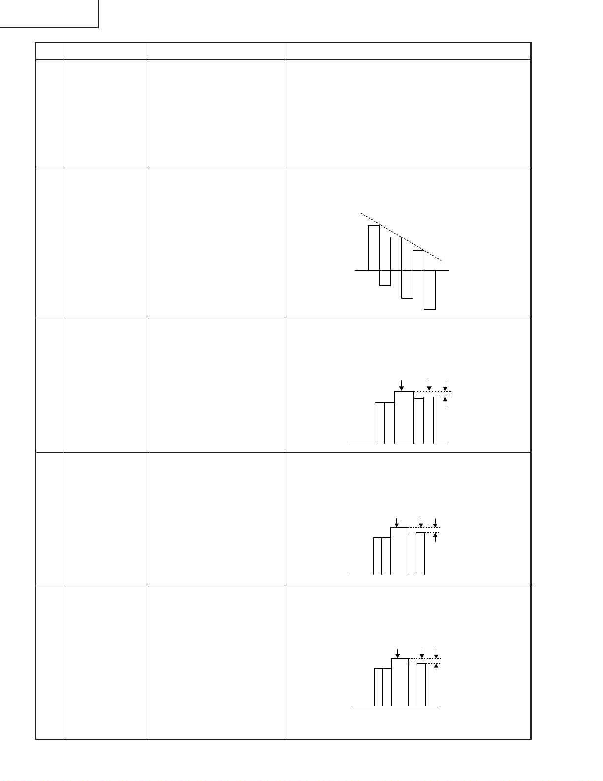
12 Video AGC
adjustment
13 Video tint
adjustment
14 NTSC colour
saturation
adjustment
1. Feed the split colour bar
signal.
2. Select the following group
and subject.
Group : VIDEO1
Subject : AGC
Make sure there are some
bit dropouts on the screen.
1. Feed the split colour bar
signal. Select the following
group and subject.
Group : VIDEO1
Subject : TINT
2. Connect the oscilloscope to
pin (4) of P801.
1. Feed the split colour bar
signal.
2. Select the following group
and subject.
Group : VIDEO1
Subject : N-COLOUR
3. Connect the oscilloscope to
pin (1) of P801.
» Using the set’s control switch or the remote
controller’s button, adjust the setting so that the
100% white signal has some bit-less.
» Using the set's control switch or the remote
controller's button, adjust the setting so that the –
(B–Y) waveform runs straight downhill.
» Using the set’s control switch or the remote
controller’s button, adjust the setting so that the
amplitude between the 100% white and red levels
be 0.20 ± 0.02 Vp-p.
15 PAL colour
saturation
adjustment
16 SECAM colour
saturation
adjustment
1. Feed the PAL colour bar
signal.
2. Select the following group
and subject.
Group : VIDEO1
Subject : P-COLOUR
3. Connect the oscilloscope to
pin (1) of P801.
1. Feed the SECAM colour
bar signal.
2. Select the following group
and subject.
Group : VIDEO1
Subject : S-COLOUR
3. Connect the oscilloscope to
pin (1) of P801.
» Using the set's control switch or the remote
controller’s button, adjust the setting so that the
amplitude between the 100% white and red levels
be 0.36 ± 0.02 Vp-p.
» Using the set's control switch or the remote
controller’s button, adjust the setting so that the
amplitude between the 100% white and red levels
be 0.50 ± 0.02 Vp-p.
30
Page 31

No. Adjusting point Adjusting conditions Adjusting procedure
XG-V10WE
AN-SD1E/S422E
17 Video input
panel signal
amplitude
adjustment
18 Video white
balance adjustment
19 DVD contrast
adjustment
1. Feed the NTSC 10-step
signal.
2. Select the following group
and subjects.
Group : VIDEO2
Subject : R1-GAIN
B1-GAIN
3. Connect the oscilloscope to
pin (1) (for R) of P1001 and
pin (3) (for G) of P1001.
4. Similarly connect the oscilloscope to the following for
the B colour.
Pin (5) of P1001 for B
Pin (3) of P1001 for G
1. Feed the NTSC
monoscope pattern signal.
2. Select the following group
and subjects.
Group : VIDEO2
Subject : R1-BLK
B1-BLK
1. Feed the 100% colour bar
signal of the 480I component signal to the G (Y) input terminal on the BNC
socket.
2. Select the following group
and subject.
Group : DVD
Subject : CONTRAST
» Select R1-GAIN. Adjust the setting so that the R
signal amplitude and the G signal amplitude be
the same.
» Do the same for the B colour.
» Using the set's control switch or the remote
controller's button, adjust the setting so that the
white balance be the same as on the monitor
screen.
» Using the set's control switch or the remote
controller's button, adjust the setting so that the
100% white signal has some bit dropouts.
20 DVD tint adjust-
ment
1. Feed the 100% colour bar
signal of the 480I component signal to the Y, Pb and
Pr input terminals on the
BNC socket. For the Y signal, feed the sync signal
only.
2. Select the following group
and subject.
Group : DVD
Subject : TINT
3. Connect the oscilloscope to
pin (2) of P801.
» Using the set's control switch or the remote
controller’s button, adjust the setting so that the
(B–Y) waveform runs straight uphill.
31
Page 32

XG-V10WE
100% White Red
AN-SD1E/S422E
No. Adjusting point Adjusting conditions Adjusting procedure
21 DVD colour
saturation
adjustment
22 DVD input panel
signal amplitude
adjustment
1. Feed the 100% colour bar
signal of the 480I component signal to the Y, Pb and
Pr input terminals on the
BNC socket.
2. Select the following group
and subject.
Group : DVD
Subject : COLOUR
3. Connect the oscilloscope to
pin (1) of P801.
1. Feed the 10-step signal to
the G (Y) input terminal on
the BNC socket.
2. Select the following group
and subjects.
Group : DVD
Subject : R1-GAIN
B1-GAIN
3. Connect the oscilloscope to
pin (1) (for R) of P1001 and
pin (3) (for G) of P1001.
4. Similarly connect the oscilloscope to the following for
the B colour.
Pin (5) of P1001 for B
Pin (3) of P1001 for G
» Using the set’s control switch or the remote
controller’s button, adjust the setting so that the
amplitude between the 100% white and red levels
be 0.10 ± 0.02 Vp-p.
» Select R1-GAIN. Adjust the setting so that the R
signal amplitude and the G signal amplitude be
the same.
» Do the same for the B colour.
23 DVD white
balance checking
24 Saw-tooth wave
correction (G),
(R)
1. Feed the NTSC
monoscope pattern signal
to the G (Y) input terminal
on the BNC socket.
2. Select the following group
and subjects.
Group : DVD
Subject : R1-BLK
B1-BLK
Make sure the lamp optical
axis has been already adjusted.
1. Feed the SXGA, 60-Hz
gray-only signal.
2. Check for uneven colour
spot on the screen.
3. Select the following group
and subject.
Group : NOKO
Subject : NOKO-G
Choose the subject NOKOR for the R colour.
» Make sure the white balance is the same as on
the monitor screen.
» If not, adjust the setting so that the white balance
be the same as on the monitor screen, using the
set's control switch or the remote controller's
button.
» When the green colour is found not uneven, turn
off the saw-tooth wave correction with S4201.
» Select NOKO-G and adjust the setting to minimize
the colour unevenness at right and left on the
screen.
For the R colour, use S4202 to turn on or off the wave
correction.
32
Page 33

No. Adjusting point Adjusting conditions Adjusting procedure
XG-V10WE
AN-SD1E/S422E
25 White balance
checking and
readjustment
26 Set-up 1. Select the following.
27 Colour-related
performance
checking
1. For the adjusting conditions, refer back to Item
Nos. 8, 19 and 24 for the
RGB, Video and DVD inputs, respectively.
DTV input
1) Feed the 720P SMPTE
(colour difference) signal.
If out of spec, take the
readjustment step below.
2) Select the following
group and subjects.
Group : DTV
Subject : CR-OFFSET
CB-OFFSET
Group : VIDEO 1
Subject : SET UP B
SET UP C
1. Feed the colour bar signal.
» Make sure the white balance is the same as on
the monitor screen. To obtain the specified white
balance, readjust the RGB, Video and DVD inputs
in this order.
» Make sure the SET UP B and SET UP C settings
are 6 and 1, respectively.
» Select the process mode L1. Check the Colour
and Tint settings.
28 Video-related
performance
checking
29 Audio-related
performance
checking
30 RGB-related
performance
checking
31 Off-timer per-
formance
checking
32 Thermistor
performance
checking
1. Feed the monoscope pattern signal.
1. Feed the stereo audio signal.
1. Feed the RGB signal.
» Select the process mode L2. Check the Picture,
Brightness and Sharpness settings.
» Select the process mode L3. Check the Bass,
Treble and Balance settings.
» Select the process mode L4. Check the Picture,
Brightness, Red, Blue, Clock, Phase, H-Pos and
V-Pos settings.
» Select the process mode OFF. Make sure that the
off-timer starts with "5" (minutes) onscreen and
counts down minute by minute each second, and
that the set turns itself off with "0" (minutes)
onscreen.
» Get the thermistor status list displayed onscreen.
33 Auto sync
performance
checking
1. Feed the phase check pattern signal.
» In the VGA, SVGA, XGA, SXGA and UXGA
modes, make sure the Clock, Phase, H-Pos and
V-Pos settings can be automatically adjusted.
33
Page 34

XG-V10WE
AN-SD1E/S422E
No. Adjusting point Adjusting conditions Adjusting procedure
34 Lens perform-
ance checking
» Using the set's control switch or the remote control-
ler, make sure the focus, zoom, keystone and lens
shift actions are as specified.
35 Delivery set-
tings
1. When the S4 delivery settings have been made, the
SET-UP signal is acceptable.
If the process mode is
» Make the following settings.
Process
adjustment
S3 "Delivery setting 3"
called up again, however,
the SET-UP signal is not
automatically accepted. In
such case, select Group:
VIDEO1 and Subject: SET
UP, change the SET UP
setting from 0 to 1, and exit
from the process mode. Or
make the S4 delivery settings again.
The methods of colour correction adjustment, after LCD panel is replaced.
When not use colour correction system.
Remote controller
setting
No. Adjusting point Adjusting conditions Adjusting procedure
1 Colour correc-
tion Rest
2 Saw-tooth wave
Correction (G),
(R)
1. Make the following choice.
Group : NOKO
Subject : CC
1. Feed the gray only RGB colour signal. (XGA 60Hz)
2. Check for uneven colour
spot on the screen.
3. Make the following choice.
Group : NOKO
» Make the following setting.
Subject : CC
Setting : 0 (colour correction OFF)
» If the colour is irregular, adjust the setting NOKO-
G or NOKO-R to minimize the right-hand and lefthand colour irregularity.
» If there is no colour irregularity, turn off the saw-
tooth correction using SW4201 (green) and
SW4202 (red).
Subject : NOKO-G
Choose the subject NOKOR for the R Colour.
34
Page 35

XG-V10WE
AN-SD1E/S422E
ADJUSTING THE PC INTERFACE (CPCi-0042CE02. PC I/F Unit)
1.Initializing the EEPROM
1) Press S2601 to call the process mode.
2) Execute the S1 command on the SSS menu. (The S1 command is used to get the PC boards initialized. Do
not carry out the S2 command because otherwise all the other adjustment data than on the PC boards would
be initialized.)
3) Make sure the program version VER.XXX on the SPECIAL menu is the latest one.
2.Adjusting the levels
2-1. Preparing the oscilloscope
1) Set the oscilloscope range to 1 Vdc/div. and 5 µs/div.
2-2. Connecting the PC interface
1) Connect the PC interface to the set and make sure the P404, P405 and P502 connectors are all tight in
position.
2) Connect a cable between the ANALOG OUTPUT terminal (signal generator) and the DSUB connector
(projector's INPUT1).
3) Set the projector's INPUT SELECT to the INPUT1 position.
4) Set the signal generator to the SXGA mode (1280 x 1024, 60 Hz, 32 tones). Adjust the output amplitude
between the black and white levels to 700 mVp-p (terminated with a 75-ohm impedance).
5) Turn on the power.
2-3. Adjusting and checking the levels
1) Press S2601 and call the process mode.
2) Adjust the SH-PHASE setting on the OUPUT3 menu to 8. (Make sure the onscreen display characters
appear crisp and clear.)
(Adjusting the A/D menu settings)
3) G-BRIGHT adjustment: Feed the black signal and adjust the G-BRIGHT setting on the A/D menu until there
are bit dropouts.
4) R-BRIGHT adjustment: Feed the black signal and adjust the R-BRIGHT setting on the A/D menu until there
are bit dropouts.
5) B-BRIGHT adjustment: Feed the black signal and adjust the B-BRIGHT setting on the A/D menu until there
are bit dropouts.
6) G-D adjustment: Feed the white signal and adjust the G-D setting on the A/D menu until there are bit
dropouts.
7) R-D adjustment: Feed the white signal and adjust the R-D setting on the A/D menu until there are bit
dropouts.
8) B-D adjustment: Feed the white signal and adjust the B-D setting on the A/D menu until there are bit
dropouts.
2-4. Adjusting the DTV settings
1) Feed the 480P Y signal to the INPUT1 terminal. Keep out the R (Pr) and B (Pb) signals.
2) G-BRIGHT adjustment: Feed the black signal and adjust the G-BRIGHT setting on the DTV menu until there
are bit dropouts.
3) CR-OFFSET adjustment: Adjust the CR-OFFSET setting to 16.
4) CB-OFFSET adjustment: Adjust the CB-OFFSET setting to 16.
5) Press S2601 to exit from the process mode.
35
Page 36

XG-V10WE
AN-SD1E/S422E
Process menu1
AD
OUTPUT1
OUTPUT2
DTV
OUTPUT3
VIDEO1
VIDEO2
DVD
NOKO
LINE
SSS
PATTERN
CVIC
LENS
SPECIAL
VIDEO2
VROS
VGOS
VBOS
R1-BLK
R1-GAIN
B1-BLK
B1-GAIN
N358 DLY
N443 DLY
PAL DLY
SECAM DLY
OUTPUT2
PSIG-H
PSIG-L
R2-BLK
R2-GAIN
G2-BLK
G2-GAIN
B2-BLK
B2-GAIN
NTSC-H
PICTURE
AGC
BRIGHT
TINT
N-COLOR
P-COLOR
S-COLOR
SET UP
SET UP B
SET UP C
VIDEO1
OUTPUT1
R1-BLK
R1-GAIN
G1-BLK
G1-GAIN
B1-BLK
B1-GAIN
OUTPUT3
RC
GC
BC
SH-PHASE
GCK-PHASE
R3-GAIN
G3-GAIN
B3-GAIN
AD
R-BRIGHT
G-BRIGHT
B-BRIGHT
R-D
B-D
G-D
DTV
G-BRIGHT
CB-OFFSET
CR-OFFSET
36
NOKO
NOKO-G
NOKO-R
CC
R-CNV-H
G-CNV-H
B-CNV-H
R-CNV-V
G-CNV-V
B-CNV-V
DVD
CONTRAST
BRIGHT
TINT
COLOR
R1-BLK
R1-GAIN
B1-BLK
B1-GAIN
Page 37

Process menu2
XG-V10WE
AN-SD1E/S422E
AD
OUTPUT1
OUTPUT2
DTV
OUTPUT3
VIDEO1
VIDEO2
DVD
NOKO
LINE
SSS
PATTERN
CVIC
LENS
SPECIAL
SPECIAL
IPL
E2PROM
ADR RD/WR
LINE
L1
L2
L3
L4
OFF
TEMP OFF
SENSER CHECK
ID CHECK
CVIC
PROGRESSIVE
ENHANCE
SCREEN
IDC
LENS
LENS AUTO
LENS TOP
LENS BOTTOM
TIME
S1
S2
S3
S4
S5
LAMP
SSS
PATTERN
RGB
RGB [50]
CROSS
RAMP
STEP
COLOR
CHR
PROGRESSIVE
MODE
LPF
LSW
PTG
LEVEL
LIMIT
FILM
THRESH
MISSTH
IDC
XEGTH
XLTH1-H
XLTH1-L
XLTH2-H
XLTH2-L
YEGTH
YLTH1-H
YLTH1-L
YLTH2-H
YLTH2-L
37
SCREEN
CUBIC-RGB
CUBIC-VIDEO
ENHANCE
BBN-RGB
BBN-VIDEO
DFC-RGB
DFC-VIDEO
Page 38

XG-V10WE
AN-SD1E/S422E
Precautions in servicing
(1) If the convergence gets out of spec during servicing, call up the process mode and select the following sub-
jects.
Group : NOKO
Subject : R-CNV-H, R-CNV-V
G-CNV-H, G-CNV-V
B-CNV-H, B-CNV-V
(H: Horizontal adjustment, V: Vertical adjustment)
Adjust the above settings in the range of 0-4. When changing each setting from the initial setting of 2, however,
the 1280 x 1024 dot display area will have a fewer number of lines.
Example 1 : When the R-CNV-H setting is changed from 2 (initial) to 4, the number of lines will be from 1280 to
1278.
Example 2 : When the R-CNV-H, G-CNV-H and B-CNV-H settings are changed to 3, 3 and 4, respectively, the
display will be 1278 x 1024 lines. But when the above settings are switched to 2, 2 and 3, respectively, the display will be 1279 x 1024 lines.
Preferably keep each setting as close to 2 as possible.
(2) When calling up the process mode, make sure the following appears onscreen.
Group : VIDEO1
Subject : SET UP B 2
SET UP C 1
Be sure to exit from this mode with the following onscreen.
Subject : SET UP 1
38
Page 39

TROUBLE SHOOTING TABLE
Checking the PWB performance
XG-V10WE
AN-SD1E/S422E
Video input in trouble
Go to "Checking the video unit
circuit".
RGB input in trouble
Feed test pattern signal from
PC.
Is specified cable connected
between PC and projector?
Yes
Is supply voltage as specified?
Yes
Does image appear?
Yes
Go to "Trouble shooting table
for PC I/F unit ".
Through-output in trouble
Through-output circuit in
trouble.
No
Use specified cable.
No
Power circuit in trouble.
No
Check the connectors, starting
from the input circuit.
Remote control in trouble
Go to "Checking the remote
control".
Checking the video system
Is the lamp on?
Yes
Is specified voltage fed to EA
connectors?
Yes
Are there signal inputs at pins (12),
(31) and (37) of SC401?
Yes
Are there signal outputs at pins (7) of
IC6014 and (7) of IC6015?
Yes
Go to "Checking IC803
(RGB signal output circuit)".
Check IC6009, IC6011,
IC6014, IC6015 and their
peripheral circuits as well
as switching circuit.
No
No
Go to "Lamp fails to light-up".
No
Check the power circuit and its parts.
No
Check the input unit circuit (IC1401,
IC1402, IC1403, IC1404, IC1405
and its peripheral circuits).
39
Page 40

XG-V10WE
AN-SD1E/S422E
Checking the video unit circuit
TROUBLE SHOOTING TABLE (Continued)
Is there video signal output at pin (7)
of IC1405?
Yes
Is there video signal input at IC4001?
Yes
Are there signal outputs at pins (6)
and (8) of IC4001?
Yes
Check the low-pass and buffer circuits
of Q6008 thru Q6014. Is the signal as
specified?
Yes
Go to "Checking IC801 (RGB signal
output circuit)".
No
Check the IC1403, IC1406 selector
switch, terminal voltage and input
circuit.
No
Check the low-pass and buffer
circuits of Q4002, Q4003 and Q4004.
No
Check IC4001 and its peripheral
circuits (bias).
No
Check Q4005 thru Q4008 and their
peripheral circuits.
Checking IC801 (RGB signal output circuit)
Go to "No colour or unusual tone",
"No Y signal" or "Out of sync".
No
Are there RGB output waveforms at
pins (31), (32) and (33) of IC803?
Yes
Are there output waveforms at pin
1 of Q6801, Q6802, Q6803?
Yes
Are there output waveforms at pin
(8), (10), (12) of SC8404?
Yes
Go to "Trouble shooting table for PC
I/F unit".
No
Check the data transfer and other
performance at pins (17) and (18) of
video IC803.
No
Check Q6801, Q6802, Q6803 and
their peripheral circuits.
No
Check IC6801, Q6807, Q6808,
Q6809 and their peripheral circuits.
40
Page 41

TROUBLE SHOOTING TABLE (Continued)
Checking the chroma and Y signals of IC801
(RGB signal output)
XG-V10WE
AN-SD1E/S422E
Are there signal inputs at pins (12),
(31) and (37) of SC401?
Yes
Are there output waveforms at pins
(7) of IC6014 (chroma signal) and
(7), (Y signal)of IC6015?
Yes
Are there signal inputs at pins (20)
(chroma signal) and (21) (Y signal)
of IC803?
Yes
Go to "Checking IC801 (RGB signal
output circuit)".
No
Go to "Checking the video unit
circuit".
No
Check the IC6009 IC6010 and IC6011
switching and their peripheral circuits.
If there is no signal at pins (1) of
IC6014 and pin (5) of IC6015 and pin
(16) of IC6010 check 3-D noise
reduction circuit (IC6009).
No
Check IC803 and its peripheral
circuits.
Checking IC806 (3-D noise reduction circuit)
and its peripheral circuits
Are there signal inputs at pins (40)
(Y signal) and (45)(chroma signal) of
IC6009?
Yes
Are there signal outputs at pins (55)
(Y signal) and (51)(chroma signal) of
IC8001?
Yes
Are there signal outputs at the
emitters of Q6010 (Y signal) and
Q6015 (chroma signal)?
Yes
Check IC6011, IC6014, IC6015 and
IC801 (RGB signal output circuit).
No
Check the buffer circuit of Q6007 thru
Q6011 as well as Q6013 thru Q6014.
No
Check IC6008, IC6010 (memory) and
their peripheral circuits.
No
Check the low-pass circuit around
Q6010, Q6012 and Q6015.
Check IC6009 (3-D noise reduction
circuit) and its peripheral circuits.
No colour or unusual tone (NTSC, PAL, PALM, PALN)
Is there chroma signal input at pin
(20) of IC801?
Yes
Are there signal outputs at pins
(46)(R-Y) and (45)(B-Y) of IC801?
Yes
Check IC804, IC805 and their
peripheral circuits.
No
Go back to the signal processing
block.
No
Check the oscillation of X801, X802,
X803 and X804 and their peripheral
circuits.
41
Page 42

XG-V10WE
AN-SD1E/S422E
TROUBLE SHOOTING TABLE (Continued)
No or unusual Y signal
Is there Y signal input at pin (21) of
IC803?
Yes
Is there Y signal output at pin (40) of
IC803?
Yes
Is there Y signal output at pin (17) of
IC804?
Yes
Check IC804 and its peripheral
circuits.
No
Go back to the signal processing
block.
No
Check IC803 and its peripheral
circuits.
No
Check IC804 and its peripheral
circuits as well as IC806 (AGC).
No or unusual horizontal sync
Is there horizontal sync pulse output
at pin (56) of IC803?
Yes
Is there horizontal sync pulse output
at pin (9) of IC802?
Yes
No
Check IC803 and its peripheral
circuits.
No
Check the pulse shaping circuit of
IC801 and IC802.
Go to "Trouble shooting table for PC
I/F unit".
No or unusual vertical sync
Is there vertical sync pulse output at
pin (4) of IC803?
Yes
Go to "Trouble shooting table for
PC I/F unit".
No
Check IC803 and its peripheral
circuits.
42
Page 43

TROUBLE SHOOTING TABLE (Continued)
Checking the output PWB unit
XG-V10WE
AN-SD1E/S422E
If there is no signal at SC6801,
go to the video system block.
If there is no signal at SC8404
and SC8405, go to "Trouble
shooting table for PC I/F unit".
Is there signal input at
SC6801?
Are voltages applied to EA
connectors and SC8404,
SC8405 and SC8502?
Yes
Are there signal outputs at
pins (17) of IC2101, IC2102,
IC2201, IC2202, IC2301,
IC2302?
Yes
Are there signal inputs at pin
(47) of IC1101, IC1102,
IC1201, IC1202, IC1301 and
IC1302?
Yes
Are there signal outputs at pins
(17), (19), (21), (28), (30) and
(32) of IC1101, IC1102,
IC1201, IC1202, IC1301 and
IC1302?
Yes
NoNo
If there is no signal at EA
connector or SC8404, SC8405
and SC8502, go to Checking
the power unitblock.
No
Check IC2101, IC2102,
IC2201, IC2202, IC2301,
IC2302 and their peripheral
circuits.
No
Check IC2101, IC2102, IC2201,
IC2202, IC2301, IC2302 and
their peripheral circuits.
No
Check IC1101, IC1102,
IC1201,IC1202, IC1301,
IC1302 and their peripheral
circuits.
If there is no signal input at
pins (1) and (32) of SC1101,
SC1201 and SC1301, check
the switching circuit and
amplifier circuit of IC1101,
IC1201, IC1301, IC1102,
IC1202, IC1302 and their
peripheral circuits.
No
Are there signal inputs at
SC1101, SC1201 and
SC1301?
Check the R, G and B panels.
Yes
Yes
No
If there is no signal input at
pins (15) and (30) of
SC1101, SC1201 and
SC1301, check IC1601
and their peripheral
circuits.
Check IC1611, IC1612,
IC1613, IC1615, IC1621,
IC1622, IC1623, IC1624
and their peripheral
circuits.
43
Page 44

XG-V10WE
AN-SD1E/S422E
TROUBLE SHOOTING TABLE (Continued)
No audio output
Are there audio signal inputs at pins
(2) and (23) of IC301?
Are there audio signal outputs at pins
(3) and (6) of IC302?
If the voltage at pin (7) of IC302 is not
as specified, check Q302, Q303 and
their peripheral circuits.
Checkig the Power Unit
No
Yes
No
Yes
Check IC302 and its peripheral
circuits, and the SP connectors and
speakers.
Check the input, the switching circuit
of IC403 and IC404, and their
peripheral circuit.
Check IC302 and its peripheral
circuits.
There is no voltage output at
EA connector.
No
Is EA connector disconnected
or loose?
No
Is AC voltage (85-264V)
applied across the BA
connector?
Yes
Is R727 broken?
Yes
Replace R727 or Q701.
Yes
Reconnect the EA connector.
No
Replace F1701.
No
There is a short-circuit along
the EA output line. Using a
tester, check the resistance
between each voltage line and
the ground.
44
Page 45

TROUBLE SHOOTING TABLE (Continued)
Power on
XG-V10WE
AN-SD1E/S422E
Is the right input selected?
Yes
Are the PC, video and LCP cables as
specified and properly connected?
Yes
With the contrast control at maximum,
does the image appear?
No
Is the voltage at CON3 (P8502)
connector as specified?
Yes
Hook up a personal computer.
Does the image appear?
No
Select the right input with remote
control.
No
Use the right cables or reconnect the
cables.
Yes
Readjust the video system.
No
Power circuit faulty.
No
Yes
Is the image as specified?
Yes
Is the image's colour as specified?
Yes
Does the on-screen display function?
Yes
Does the remote control function?
Yes
End
Go to "Checking the clock circuit and
its peripheral circuits".
No
Check the sync signal circuit and its
peripheral circuits.
No
Check the video circuit and its
peripheral circuits.
No
Go to "Checking the OSD circuit and
its peripheral circuits".
No
Go to "Checking the remote control".
45
Page 46

XG-V10WE
AN-SD1E/S422E
Is the lamp out of socket?
Yes
Reconnect the
lamp into socket.
TROUBLE SHOOTING TABLE (Continued)
Lamp fails to light-up
Turn on the power switch. Is
Yes
discharging sound heard from
the lamp?
No
No
No
Check the power circuit.
Replace the
lamp.
Is the ballast cooling fan
running?
Yes
Replace the ballast.
Is DC 360V voltage applied
between PL1 and PL2
connector pins?
Is 3.5V or higher voltage
Yes
applied between pins (1), (2)
and (4) of ballast’s D
connector?
Is power EA connector
disconnected?
Yes
Reconnect the
connector into socket.
No
Yes
No
No
Check the
microcomputer circuit.
46
Page 47

TROUBLE SHOOTING TABLE FOR PC I/F UNIT-1
Checking the PC PWB
0
Does the user menu appear
Yes
onscreen?
No
XG-V10WE
AN-SD1E/S422E
Is screen color as specified?
No
Adjust the output system in the
process adjustment.
0
Check the RGB input.
(Check the basic signal flow.
The COMPONENT and VIDEO
signals flow in the same way
from CVIC_IC up to DAC OUT.
No checking is therefore
needed from the CVIC on.)
Check the COMPONENT
input.
(The signal flows in the same
circuit as with the RGB input.
Check the SOG (Sync On
Green) circuit and the color
adjust circuit, among others.)
Yes
Check the GA4 and its
peripherals.
Overwrite the flash ROM.
Check the VIDEO input.
(The VIDEO signal comes to
CVIC_IC via a different route
from the RGB input signal. So
check the VIDEO DACÆEPLL
IC.)
Check the DVI input.
(Check the DVI digital input
and the DVI analog input
alike.)
End
47
Page 48

XG-V10WE
AN-SD1E/S422E
TROUBLE SHOOTING TABLE FOR PC I/F UNIT-2
Checking the RGB input
Feed the sync separation type
RGB signal to INPUT1 or
INPUT2.
1
Using panel key or remote
controller, select INPUT1 or
INPUT2.
2
Does image appear onscreen?
Yes
Is the image free of distortion?
Yes
3
» Checking the sync (H/V) signal separation type
No
Check the video input.
No
Check the sync signal.
Do the R, G and B colors all
appear?
Yes
Execute the AUTOSYNC
command.
Is the image contour as
specified?
Yes
Is the vertical stripe pattern
as specified?
Yes
No problem with the RGB input
No
Check the R, G and B signals.
No
No
PLL, ADC or their peripherals
defective.
48
Page 49

TROUBLE SHOOTING TABLE FOR PC I/F UNIT-3
Checking the video input
Check up the input signal
settings.
XG-V10WE
AN-SD1E/S422E
Is there video signal at C77
land?
Yes
Check the sync signal.
Yes
CVIC_IC or ADCÆEPLL circuit
defective.
No
Input PWB defective.
Checking the input signal settings
Are connector connections
and input menu selection as
specified?
Yes
No
Select the right ones.
Are connectors properly
connected?
Yes
Input signal settings completed.
No
2
Reconnect the connectors.
1
49
Page 50

XG-V10WE
AN-SD1E/S422E
TROUBLE SHOOTING TABLE FOR PC I/F UNIT-4
» Check the H/V separation type sync signal.
Checking the sync signal
Is there vertical sync signal at
TL134?
Yes
Is there horizontal sync signal
at TL133?
Yes
Is there vertical sync signal at
TL131?
Yes
Is there horizontal sync signal
at TL130?
Yes
Are both the vertical and
horizontal sync signals in
good timing?
No
No
No
Check up the input signal
settings.
Input PWB defective.
No
No
PC board s sync signal
selector circuit or its
peripherals defective.
Yes
No problem with the sync
signal.
Is the signal generator (input
source) as specified?
Yes
Input PWB defective.
No
Make proper signal source
settings.
2
50
Page 51

TROUBLE SHOOTING TABLE FOR PC I/F UNIT-5
» Check the R, G and B (Y, Pb and Pr) colors.
Checking the R, G and B colors
XG-V10WE
AN-SD1E/S422E
Is the signal type set for RGB?
Yes
Call the process mode.
Select R, G and B individually
on the pattern menu.
Check the GA4 peripherals.
Set the signal generator for the
tone signal to check the input
signal.
No
Set the type for RGB.
Watch the TP1, TP2 and TP3
outputs on oscilloscope screen
to check the tine signal.
Are the TP1, TP2 and TP3
outputs as specified?
Yes
CVIC_IC or its peripherals
defective.
No
Are there signals at
C69 and C61?
Yes
ADC·PLL_IC or its
peripherals defective.
51
No
Input PWB defective.
Page 52

XG-V10WE
AN-SD1E/S422E
TROUBLE SHOOTING TABLE FOR PC I/F UNIT-6
Checking the GA4 peripherals
Select R, G and B individually
on the pattern menu.
Are the R, G and B video
outputs as specified?
No
Measure the FB4, FB5, FB6,
FB10, FB11 and FB12 outputs
on oscilloscope screen.
Are the pattern menu-selected
settings and the above
measurements consistent?
No
Are there clocks at pins (31),
(32) and (33) of IC50 and
IC51?
Yes
Measure the TL106 thru TL111
outputs on oscilloscope
screen.
Yes
GA4 peripherals checking
complete.
Yes
Output PWB defective.
No
Is there clock at TL114?
Is there 54-MHz clock at
FL110?
CVIC_IC defective.
Yes
No
GA4 defective.
No
Yes
X5 (quartz oscillator)
defective.
Are the pattern menu-selected
settings and the above
measurements consistent?
Yes
GA4 defective.
No
CVIC_IC defective.
52
Page 53

TROUBLE SHOOTING TABLE FOR PC I/F UNIT-7
XG-V10WE
AN-SD1E/S422E
Checking the COMPONENT input
Feed the COMPONENT signal
to INPUT1 or INPUT 2.
Using panel key or remote
controller, select INPUT1 or
INPUT2.
Does image appear onscreen?
Yes
4
Are the colors as specified?
No
Is the signal type of
COMPONENT?
Yes
No
Check the SOG circuit.
Yes
No
Set the signal type to
COMPONENT.
» Check the COMPONENT (1080I, 720P, 480P, etc.:
480I not included) signals.
Carry out the process
adjustment.
4
Is the image contour as
specified?
Yes
No problem with the
COMPONENT input.
No
IC4 (CXA3516R) or IC25
(CVIC_IC) defective.
53
Page 54

XG-V10WE
AN-SD1E/S422E
TROUBLE SHOOTING TABLE FOR PC I/F UNIT-8
Checking the SOG circuit
Measure the TL136 output on
oscilloscope screen.
Is the composite sync signal
reproduced in good timing?
No
Measure the C69 land on
oscilloscope screen.
Does the Y signal contain
sync signal?
Yes
SOG sync separation circuit
defective.
Yes
No problem with the SOG
circuit.
No
Check the input signal settings.
Input PWB defective.
54
Page 55

TROUBLE SHOOTING TABLE FOR PC I/F UNIT-9
Checking the VIDEO input
Feed the composite video
signal to INPUT4 or INPUT 5.
Using panel key or remote
controller, select INPUT4 or
INPUT5.
Select the VIDEO signal type
on user menu.
5
XG-V10WE
AN-SD1E/S422E
Does image appear onscreen?
Yes
Is the image free of distortion?
Yes
Are the colors as specified?
Yes
No problem with the VIDEO
input.
Measure the following outputs on
oscilloscope screen: at pin (5)(R)
of IC324, pin (3)(G) of IC326 and
pin (5)(B) of IC326.
Is the video signal level
between VRB and VRT?
No
No
Check the VIDEO sync signal.
No
» VRB: Bottom reference voltage at video ADC
Yes
» VRT: Top reference voltage at video ADC
Check the VIDEO sync signal.
Carry out the process
adjustment.
5
No
Measure the output at pin (5) or
(6) of IC323 on oscilloscope
screen.
Is the clamp pulse as
specified?
No
Check the VIDEO sync signal.
CVIC_IC or its peripherals
defective.
IC310 or CVIC_IC defective.
Yes
» Checking the clamp pulse
Clamp level setting IC (IC316,
IC327 or IC323) or its
peripherals defective.
55
Page 56

XG-V10WE
AN-SD1E/S422E
TROUBLE SHOOTING TABLE FOR PC I/F UNIT-10
Checking the VIDEO sync signal
» Checking the VIDEO vertical sync signal.
Measure the TL135 output on
oscilloscope screen.
Is the vertical sync signal as
specified?
Yes
Measure the TL132 output on
oscilloscope screen.
Is the horizontal sync signal as
specified?
Yes
Are there horizontal and
vertical sync signals at TL130
and TL131?
Yes
Is the pulse output at pin (4) of
IC328 in the same timing as
the horizontal signal?
Yes
Is the pulse output at pin (5) of
IC328 in the same timing as
the pulse at pin (4)?
Yes
No
» Checking the VIDEO
vertical sync signal
No
Check the input signal settings.
Input PC board defective.
No
IC302 or its peripherals
defective.
No
CVIC_IC or its peripherals
defective.
No
CVIC_IC or its peripherals
defective.
Is there 69-MHz or so clock at
FL102?
Yes
No problem with the VIDEO
sync signal and clock.
No
IC328 (PLL_IC) or its
peripherals defective.
56
Page 57

TROUBLE SHOOTING TABLE FOR PC I/F UNIT-11
Checking the DVI digital input
XG-V10WE
AN-SD1E/S422E
Feed the DVI digital signal to
INPUT3.
Select the INPUT3 input.
Does image appear onscreen?
Yes
Is the image free of distortion?
Yes
Are the colors as specified?
Yes
No problem with the DVI
digital input.
Note:
In order to establish the plug & play fashion, first connect the cable
to INPUT3 and then turn on the computer power (signal generator).
No
No
No
IC298 (Sil151) or its
peripherals defective.
Is the sync signal as specified?
Yes
Is the clock as specified?
Yes
IC298 (Sil151) or its
peripherals defective.
No
No
» Measure the C463 land for the vertical sync
signal and the C464 land for the horizontal sync
signal (on the back the PC board).
» Measure the R685 value for the clock (on the
back of the PC board).
IC298 (Sil151) or its
peripherals defective.
57
Page 58

XG-V10WE
AN-SD1E/S422E
TROUBLE SHOOTING TABLE FOR PC I/F UNIT-12
Checking the DVI analog input
With the plug & play fashion
established, feed the DVI
analog signal to INPUT3.
Select the INPUT3 input.
Does image appear onscreen?
Yes
Yes
3
Is the image free of distortion?
No
Is the sync signal of separate
type?
Yes
Is the sync signal as specified?
(Check pin (6) of IC330 for the
vertical sync signal and pin (6)
of IC331 for the horizontal sync
signal.)
No
Sync separation circuit IC330
or IC331 (TL712CPW) or its
peripherals defective.
No
Are there R, G and B signals?
(Check to see if the R, G and B
signals are coming to pins
(126), (136) and (141) of IC4.)
Yes
No
Check the DVI_SOG circuit.
Yes
Are there horizontal and
vertical sync signals at TL130
and TL131?
Yes
CVIC_IC or IC4 peripherals
defective.
No
DVI connector or its
peripherals defective.
No
IC302 or its peripherals
defective.
58
Page 59

XG-V10WE
AN-SD1E/S422E
TROUBLE SHOOTING TABLE FOR PC I/F UNIT-13
» The SOG component of the DVI analog signal is separated
Checking the DVI_SOG
in the CXA3516R circuit. The Green signal is fed to the
SOGIN2 terminal. The DVI SOG sync signal is selected
by the bus switch (IC23).
Is there horizontal sync signal
at TL82?
No
Is there Green signal at pin
(135) of IC4?
Yes
IC4 or IIC bus control
peripherals defective.
Is there sync signal at TL136?
No
Are pins (4) of IC23 and IC336
at low level?
Yes
Yes
No
DVI connector or its
peripherals defective.
Yes
No
No problem with the DVI_SOG.
IC23 or IC336 defective.
CPU port defective.
59
Page 60

XG-V10WE
AN-SD1E/S422E
CHASSIS LAYOUT / CHASSIS-ANORDNUNG
H
G
F
XG-V10WE
AN-SD1E/S422E
E
D
C
B
A
118
879654321
119
1716 1918151413121110
Page 61

XG-V10WE
AN-SD1E/S422E
BLOCK DIAGRAM / BLOCKSCHALTBILD
H
G
F
XG-V10WE
AN-SD1E/S422E
E
D
C
B
A
120
879654321
121
1716 1918151413121110
Page 62

XG-V10WE
AN-SD1E/S422E
OVERALL WIRING DIAGRAM / GESAMTSCHALTPLAN
H
G
F
XG-V10WE
AN-SD1E/S422E
E
D
C
B
A
122
879654321
123
1716 1918151413121110
Page 63

XG-V10WE
AN-SD1E/S422E
DESCRIPTION OF
SCHEMATIC DIAGRAM
H
VOLTAGE MEASUREMENT CONDITION:
1. Voltages at test points are measured at the
supply voltage of AC 230V. Signals are fed by a
color bar signal generator for servicing purpose and
the above voltages are measured with a 20k ohm/V
tester.
G
WAVEFORM MEASUREMENT CONDITION:
1. Waveforms at test points are observed at the supply
voltage of AC 230V. Signals are fed by a color bar
signal generator for servicing purpose.
INDICATION OF RESISTOR & CAPACI-
F
TOR:
RESISTOR
1. The unit of resistance “Ω” is omitted.
(K=kΩ=1000 Ω, M=MΩ).
2. All resistors are ± 5%, unless otherwise noted.
(J= ± 5%, F= ± 1%, D= ± 0.5%)
3. All resistors are 1/10W, unless otherwise noted.
E
4. All resistors are Carbon type, unless otherwise
noted.
C : Solid
S : Oxide Film T : Special
N : Metal Coating
CAPACITOR
1. All capacitors are µF, unless otherwise noted.
D
(P=pF=µµF).
2. All capacitors are 50V, unless otherwise noted.
3. All capacitors are Ceramic type, unless otherwise
noted.
(ML): Mylar (TA): Tantalum
(PF): Polypro Film (ST): Styrol
C
CAUTION:
This circuit diagram is original one, therefore there may be a
slight difference from yours.
SAFETY NOTES:
1. DISCONNECT THE AC PLUG FROM THE AC
OUTLET BEFORE REPLACEING PARTS.
B
2. SEMICONDUCTOR HEAT SINKS SHOULD BE
REGARDED AS POTENTIAL SHOCK HAZARDS
WHEN THE CHASSIS IS OPERATING.
IMPORTANT SAFETY NOTICE:
PARTS MARKED WITH “å” ( ) ARE
IMPORTANT FOR MAINTAINING THE SAFETY OF
A
THE SET. BE SURE TO REPLACE THESE PARTS
WITH SPECIFIED ONES FOR MAINTAINING THE
SAFETY AND PERFORMANCE OF THE SET.
W
: Cement
BESCHREIBUNG DES
SCHEMATISCHEN SCHALTPLANS
SPANNUNGSMESSUNGEN:
1. Spannungen an den Prüfpunkten werden bei einer
Netzspannung von 230V gemessen, Signale werden
für die Wartung mit einem Farbbalken-Signal generator
zugeführt, und Spannungen werden mit einem
Meßinstrument (20 k /V) ermittelt.
SIGNALFORMMESSUNGEN:
1. Die Wellenformen an den T estpunkten werden bei einer
Netzspannung von 230V verfolgt. Signale werden für
die Wartung mit einem Farbbalken-Signal generator
zugeführt.
BEZEICHNUNG DES WIDERSTANDS UND
KONDENSATORS:
WIDERSTAND
1. Die Widerstandseinheit “ ” wird weggelassen.
(K=k =1000 , M=M )
2. Alle Widerstände haben ± 5%, sofern nicht anders
angegeben.(J= ± 5%, F= ± 1%, D= ± 0.5%)
3. Alle Widerstände haben 1/10W, sofern nicht anders
angegeben.
4. Alle Widerstände sind Kohletyp, sofern nicht anders
angegeben.
C : Solid
S : Oxide Film T : Special
N : Metal Coating
KONDENSATOR
1. Die Kapazitätseinheit ist µF, sofern nicht anders
angegeben. (P=pF=µµF).
2. Alle Kondensatoren haben 50V, sofern nicht anders
angegeben.
3. Alle Kondensatoren sind Keramiktyp, sofern nicht
anders angegeben.
(ML): Mylar (TA): Tantal
(PF): Polyprofilm (ST): Styrol
ACHTUNG:
Bei diesem Schaltplan handelt es sich um den ursprünglichen.
Esönnen daher geringfügige Unterschiede zu dem lhrem bestehen.
SICHERHEITSANMERKUNGEN:
1. VOR DEM AUSWECHSELN VON TEILEN MUSS UNBEDINGT
NETZSTECKER AUS DER NETZSTECKDOSE GEZOGEN WERDEN.
2. DIE WARMEABLEITER DER HALBLEITER SOLLTEN BEIM
BETRIEB DES CHASSIS ALS MÖGLICHE URSACHEN VON
GEFÄHRLICHEN ELEKTRISCHEN SCHLÄGEN BETRACHTET
WERDEN.
WICHTIGE SICHERHEITSANMERKUNGEN:
MIT “å”( )BEZEICHNETEN TEILE SIND
BESONDERS WICHTIG FÜR DIE AUFRECHTERHAL TUNG
DER SICHERHEIT . BEIM WECHDIESER TEILE SOLL TEN
DIE VORGESCHRIEBENEN TEILE IMMER VERWENDET
WERDEN, UM SOWOHL DIE SICHERHEIT ALS AUCH DIE
LEISTUNG DES GERÄTES AUFRECHTZUERHALTEN.
W
: Cement
87109654321
124
Page 64

WAVEFORMS / WELLENFORMEN
XG-V10WE
AN-SD1E/S422E
1 SC1101 13-pin
(RSIG11)
H : 10µsec/div
V : 2V/div
5 SC1301 13-pin
(BSIG11)
H : 10µsec/div
V : 2V/div
9 P801 4-pin
(B-Y)
H : 10µsec/div
V : 0.5V/div
2 SC1101 11-pin
(RSIG9)
H : 10µsec/div
V : 2V/div
6 SC1301 11-pin
(BSIG9)
H : 10µsec/div
V : 2V/div
0 IC802 9-pin
(HD)
H : 10µsec/div
V : 2V/div
3 SC1201 13-pin
(GSIG11)
H : 10µsec/div
V : 2V/div
7 P801 1-pin
(R)
H : 10µsec/div
V : 0.5V/div
q Q6003 Emitter
(4FSC)
H : 50nsec/div
V : 1V/div
4 SC1201 11-pin
(GSIG9)
H : 10µsec/div
V : 2V/div
8 P801 2-pin
(B)
H : 10µsec/div
V : 0.5V/div
w IC803 21-pin
(Y-signal)
H : 10µsec/div
V : 200mV/div
e IC803 20-pin
(CHROMA signal)
H : 10µsec/div
V : 200mV/div
u P1001 4-pin
(TPG2)
H : 10µsec/div
V : 2V/div
r P1001 1-pin
(TPR1)
H : 10µsec/div
V : 2V/div
i P1001 5-pin
(TPB1)
H : 10µsec/div
V : 2V/div
125
t P1001 2-pin
(TPR2)
H : 10µsec/div
V : 2V/div
o P1001 6-pin
(TPB2)
H : 10µsec/div
V : 2V/div
y P1001 3-pin
(TPG1)
H : 10µsec/div
V : 2V/div
1716 1918151413121110
Page 65

XG-V10WE
AN-SD1E/S422E
Ë
OUTPUT UNIT / AUSGABEEINHEIT-1/9
H
G
F
XG-V10WE
AN-SD1E/S422E
E
D
C
B
A
126
879654321
127
1716 1918151413121110
Page 66

XG-V10WE
AN-SD1E/S422E
Ë
OUTPUT UNIT / AUSGABEEINHEIT-2/9
H
G
F
XG-V10WE
AN-SD1E/S422E
E
D
C
B
A
128
879654321
129
1716 1918151413121110
Page 67

XG-V10WE
AN-SD1E/S422E
Ë
OUTPUT UNIT / AUSGABEEINHEIT-3/9
H
G
F
XG-V10WE
AN-SD1E/S422E
E
D
C
B
A
130
879654321
131
1716 1918151413121110
Page 68

XG-V10WE
AN-SD1E/S422E
Ë
OUTPUT UNIT / AUSGABEEINHEIT-4/9
H
G
F
XG-V10WE
AN-SD1E/S422E
E
D
C
B
A
132
879654321
133
1716 1918151413121110
Page 69

XG-V10WE
AN-SD1E/S422E
Ë
OUTPUT UNIT / AUSGABEEINHEIT-5/9
H
G
F
XG-V10WE
AN-SD1E/S422E
E
D
C
B
A
134
879654321
135
1716 1918151413121110
Page 70

XG-V10WE
AN-SD1E/S422E
Ë
OUTPUT UNIT / AUSGABEEINHEIT-6/9
H
G
F
XG-V10WE
AN-SD1E/S422E
E
D
C
B
A
136
879654321
137
1716 1918151413121110
Page 71

XG-V10WE
AN-SD1E/S422E
Ë
OUTPUT UNIT / AUSGABEEINHEIT-7/9
H
G
F
XG-V10WE
AN-SD1E/S422E
E
D
C
B
A
138
879654321
139
1716 1918151413121110
Page 72

XG-V10WE
AN-SD1E/S422E
Ë
OUTPUT UNIT / AUSGABEEINHEIT-8/9
H
G
F
XG-V10WE
AN-SD1E/S422E
E
D
C
B
A
140
879654321
141
1716 1918151413121110
Page 73

XG-V10WE
AN-SD1E/S422E
Ë
OUTPUT UNIT / AUSGABEEINHEIT-9/9
H
G
F
XG-V10WE
AN-SD1E/S422E
E
D
C
B
A
142
879654321
143
1716 1918151413121110
Page 74

XG-V10WE
AN-SD1E/S422E
Ë
OUTPUT SUB UNIT / ZUSATZ-AUSGABEEINHEIT
H
G
F
XG-V10WE
AN-SD1E/S422E
E
D
C
B
A
144
879654321
145
1716 1918151413121110
Page 75

XG-V10WE
AN-SD1E/S422E
Ë
SIGNAL UNIT / SIGNALEINHEIT-1/5
H
G
F
XG-V10WE
AN-SD1E/S422E
E
D
C
B
A
146
879654321
147
1716 1918151413121110
Page 76

XG-V10WE
AN-SD1E/S422E
Ë
SIGNAL UNIT / SIGNALEINHEIT-2/5
H
G
F
XG-V10WE
AN-SD1E/S422E
E
D
C
B
A
148
879654321
149
1716 1918151413121110
Page 77

XG-V10WE
AN-SD1E/S422E
Ë
SIGNAL UNIT / SIGNALEINHEIT-3/5
H
G
F
XG-V10WE
AN-SD1E/S422E
E
D
C
B
A
150
879654321
151
1716 1918151413121110
Page 78

XG-V10WE
AN-SD1E/S422E
Ë
SIGNAL UNIT / SIGNALEINHEIT-4/5
H
G
F
XG-V10WE
AN-SD1E/S422E
E
D
C
B
A
152
879654321
153
1716 1918151413121110
Page 79

XG-V10WE
AN-SD1E/S422E
Ë
SIGNAL UNIT / SIGNALEINHEIT-5/5
H
G
F
XG-V10WE
AN-SD1E/S422E
E
D
C
B
A
154
879654321
155
1716 1918151413121110
Page 80

XG-V10WE
AN-SD1E/S422E
Ë
LED UNIT / LED-EINHEIT
H
H
G
G
F
F
E
E
D
D
C
C
B
B
A
A
87109654321
654321
156
Page 81

XG-V10WE
AN-SD1E/S422E
Ë
R/C RECEIVER-1 UNIT / FERNBEDIENUNGSEMPFÄNGERSEINHEIT 1
H
G
F
E
D
C
B
A
1716 1918151413121110
654321
157
Page 82

XG-V10WE
AN-SD1E/S422E
Ë
R/C RECEIVER-2 UNIT / FERNBEDIENUNGSEMPFÄNGERSEINHEIT 2
H
G
F
XG-V10WE
AN-SD1E/S422E
E
D
C
B
A
158
879654321
159
1716 1918151413121110
Page 83

XG-V10WE
AN-SD1E/S422E
Ë
INPUT UNIT / EINGANGSEINHEIT-1/3
H
G
F
XG-V10WE
AN-SD1E/S422E
E
D
C
B
A
160
879654321
161
1716 1918151413121110
Page 84

XG-V10WE
AN-SD1E/S422E
Ë
INPUT UNIT / EINGANGSEINHEIT-2/3
H
G
F
XG-V10WE
AN-SD1E/S422E
E
D
C
B
A
162
879654321
163
1716 1918151413121110
Page 85

XG-V10WE
AN-SD1E/S422E
Ë
INPUT UNIT / EINGANGSEINHEIT-3/3
H
G
F
XG-V10WE
AN-SD1E/S422E
E
D
C
B
A
164
879654321
165
1716 1918151413121110
Page 86

XG-V10WE
AN-SD1E/S422E
Ë
POWER AND INLET UNIT / NETZTEILEINHEIT UND EINLASSEINHEIT
H
G
XG-V10WE
AN-SD1E/S422E
F
(POWER)
(INLET)
E
D
C
B
A
166
879654321
167
1716 1918151413121110
Page 87

XG-V10WE
AN-SD1E/S422E
Ë
PC I/F UNIT / PC-I/F-EINHEIT-1/8
H
G
F
XG-V10WE
AN-SD1E/S422E
E
D
C
B
A
168
879654321
169
1716 1918151413121110
Page 88

XG-V10WE
AN-SD1E/S422E
Ë
PC I/F UNIT / PC-I/F-EINHEIT-2/8
H
G
F
XG-V10WE
AN-SD1E/S422E
E
D
C
B
A
170
879654321
171
1716 1918151413121110
Page 89

XG-V10WE
AN-SD1E/S422E
Ë
PC I/F UNIT / PC-I/F-EINHEIT-3/8
H
G
F
XG-V10WE
AN-SD1E/S422E
E
D
C
B
A
172
879654321
173
1716 1918151413121110
Page 90

XG-V10WE
AN-SD1E/S422E
Ë
PC I/F UNIT / PC-I/F-EINHEIT-4/8
H
G
F
XG-V10WE
AN-SD1E/S422E
E
D
C
B
A
174
879654321
175
1716 1918151413121110
Page 91

XG-V10WE
AN-SD1E/S422E
Ë
PC I/F UNIT / PC-I/F-EINHEIT-5/8
H
G
F
XG-V10WE
AN-SD1E/S422E
E
D
C
B
A
176
879654321
177
1716 1918151413121110
Page 92

XG-V10WE
AN-SD1E/S422E
Ë
PC I/F UNIT / PC-I/F-EINHEIT-6/8
H
G
F
XG-V10WE
AN-SD1E/S422E
E
D
C
B
A
178
879654321
179
1716 1918151413121110
Page 93

XG-V10WE
AN-SD1E/S422E
Ë
PC I/F UNIT / PC-I/F-EINHEIT-7/8
H
G
F
XG-V10WE
AN-SD1E/S422E
E
D
C
B
A
180
879654321
181
1716 1918151413121110
Page 94

XG-V10WE
AN-SD1E/S422E
Ë
PC I/F UNIT / PC-I/F-EINHEIT-8/8
H
G
F
XG-V10WE
AN-SD1E/S422E
E
D
C
B
A
182
879654321
183
1716 1918151413121110
Page 95

XG-V10WE
AN-SD1E/S422E
PRINTED WIRING BOARD ASSEMBLIES
LEITERPLATTENEINHEITEN
H
G
F
E
D
C
B
A
Output Unit (Wiring Side)
Ausgabeeinheit (Leiterbahnseite)
654321
184
Page 96

XG-V10WE
AN-SD1E/S422E
H
G
F
E
D
C
B
A
Output Unit (Component Side)
Ausgabeeinheit (Bestückungsseite)
654321
185
Page 97

XG-V10WE
AN-SD1E/S422E
H
G
F
Output Sub Unit (Wiring Side)
Zusatz-Ausgabeeinheit (Leiterbahnseite)
E
D
R/C Receiver-1 Unit (Wiring Side)
Fernbedienungsempfängerseinheit 1
C
(Leiterbahnseite)
B
R/C Receiver-2 Unit (Wiring Side)
Fernbedienungsempfängerseinheit
2(Leiterbahnseite)
A
LED Unit (Wiring Side)
LED einheit (Leiterbahnseite)
654321
186
Page 98

XG-V10WE
AN-SD1E/S422E
H
G
F
Output Sub Unit (Component Side)
Zusatz-Ausgabeeinheit (Bestückungsseite)
E
D
R/C Receiver-1 Unit (Component
C
Side)
Fernbedienungsempfängerseinheit
1(Bestückungsseite)
B
R/C Receiver-2 Unit (Component Side)
Fernbedienungsempfängerseinheit 2
(Bestückungsseite)
A
LED Unit (Component Side)
LED einheit (Bestückungsseite)
654321
187
Page 99

XG-V10WE
AN-SD1E/S422E
H
G
F
E
D
C
B
A
Signal Unit (Wiring Side)
Signaleinheit (Leiterbahnseite)
654321
188
Page 100

XG-V10WE
AN-SD1E/S422E
H
G
F
E
D
C
B
A
Signal Unit (Component Side)
Signaleinheit (Bestückungsseite)
654321
189
 Loading...