

Page 1
TopPage
XG-PH70X/XG-PH70X-N (1st. Edition)
SERVICE MANUAL
No. SX6Z1XGPH70X/
MULTIMEDIA PROJECTOR
XG-PH70X
MODELS
In the interests of user-safety (Required by safety regulations in some countries) the set should be restored to its original condition and only parts identical to those specified should be used.
XG-PH70X-N
CONTENTS
SAFETY PRECAUTION
IMPORTANT SERVICE SAFETY NOTES
Precautions for using lead-free solder ..............vi
CHAPTER 1. OPERATION MANUAL
[1] SPECIFICATIONS ......................................... 1-1
[2] Operation Manual........................................... 1-2
[3] DIMENSIONS ................................................ 1-9
[4] Maintenance Indicators................................ 1-10
[5] Regarding the Lamp..................................... 1-12
CHAPTER 2. REMOVING OF MAJOR PARTS
[1]
Removing the Lamp Unit
[2] Removing the Top Cover................................ 2-2
[3] Removing the Lens Hood............................... 2-3
[4] Removing the Lens Cap................................. 2-3
[5] Removing the Lens Trim ................................ 2-4
[6] Removing the Standard Lens......................... 2-4
[7] Removing the Top Cabinet............................. 2-5
[8] Removing the Handle Bracket3 ..................... 2-6
[9] Removing the PWB Units............................... 2-7
[10]
Removing the Optical Engine and Lens Shift
[11] Removing the Terminal Unit......................... 2-10
[12] Removing the Filter Unit............................... 2-11
[13] Removing the IR (Rear) Unit........................ 2-11
[14]
Removing the Power Unit and Audio Unit
CHAPTER 3. ELECTRICAL ADJUSTMENT
[1] ELECTRICAL ADJUSTMENT........................ 3-1
[2] PC I/F adjustment method ............................. 3-3
[3] Special 232c command for factory................. 3-4
[4] SERVICE MODE............................................ 3-5
[5] Failure mode when the lamp does not light
up even when powered on............................. 3-7
................................ 2-1
.............i
........ 2-8
........ 2-12
CHAPTER 4. TROUBLESHOOTING TABLE
[1] TROUBLESHOOTING TABLE ......................4-1
CHAPTER 5. BLOCK DIAGRAM/OVERALL WIRING
DIAGRAM
[1] BLOCK DIAGRAM.........................................5-1
[2] OVERALL WIRING DIAGRAM......................5-3
CHAPTER 6. PRINTED WIRING BOARD
[1] MAIN Unit ......................................................6-1
[2] FORMATTER Unit .........................................6-5
[3] POWER Unit..................................................6-7
[4] FILTER/P.F.C CONTROL/LVPS CON-
TROL Unit......................................................6-9
[5] PC I/F Unit ...................................................6-11
[6] DIRECT OFF Unit........................................6-13
[7] AUDIO Unit..................................................6-14
[8] KEYPAD Unit...............................................6-15
[9] TERMINAL Unit ...........................................6-17
[10] IR (FRONT)/IR (REAR)/LAMP1 COVER/
LAMP2 COVER Unit/INDEX Unit ................6-18
CHAPTER 7. WAVEFORMS
[1] WAVEFORMS ...............................................7-1
CHAPTER 8. SCHEMATIC DIAGRAM
[1] DESCRIPTION OF SCHEMATIC DIA-
GRAM............................................................8-1
[2] SCHEMATIC DIAGRAM................................8-2
Parts Guide
Parts marked with " " are important for maintaining the safety of the set. Be sure to replace these parts with specified ones for maintaining the
safety and performance of the set.
This document has been published to be used for
after sales service only.
The contents are subject to change without notice.
Page 2
XG-PH70X/XG-PH70X-N (1st. Edition)
XG-PH70X
SAFETY PRECAUTION
IMPORTANT SERVICE SAFETY NOTES
IMPORTANT SERVICE SAFETY NOTES (for USA)
Service work should be performed only by qualified service technicians who are
thoroughly familiar with all safety checks and servicing guidelines as follows:
WARNING
1. For continued safety, no modification of any circuit
should be attempted.
2. Disconnect AC power before servicing.
BEFORE RETURNING THE PROJECTOR:
(Fire & Shock Hazard)
Before returning the projector to the user, perform
the following safety checks:
1. Inspect lead wires are not pinched between the chassis
and other metal parts of the projector.
2. Inspect all protective devices such as non-metallic
control knobs, insulating materials, cabinet backs,
adjustment and compartment covers or shields,
isolation resistor-capacity networks, mechanical
insulators, etc.
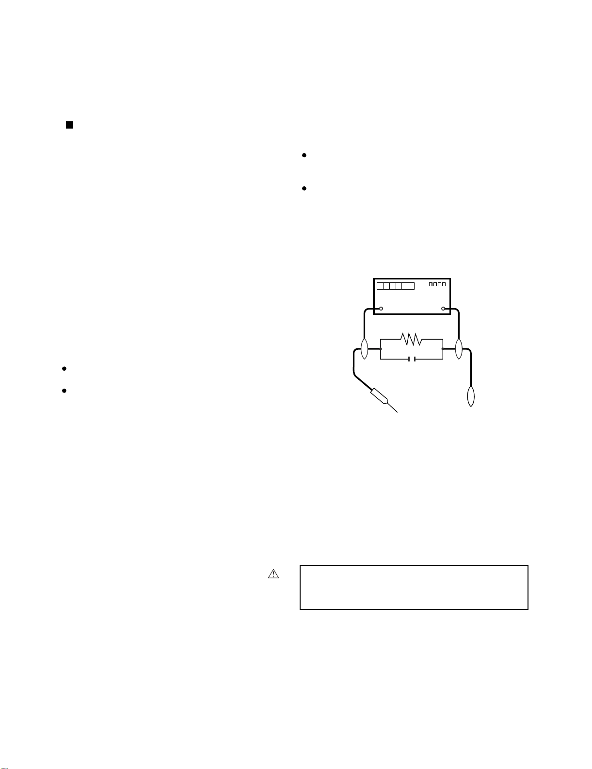
3. To be sure that no shock hazard exists, check for
current leakage in the following manner:
Plug the AC cord directly into a 120-volt AC outlet,
(Do not use an isolation transformer for this test).
Using two clip leads, connect a 1.5k ohm, 10 watt
resistor paralleled by a 0.15µF capacitor in parallel
between all exposed metal cabinet parts and earth
ground.
Service Manual
Use an AC voltmeter with sensitivity of 5000 ohm per
volt., or higher, sensitivity to measure the AC voltage
drop across the resistor.
All checks must be repeated with the AC plug
connection reversed. (If necessary, a non-polarized
adapter plug must be used only for the purpose of
completing these checks.)
Any reading of 0.4 volts RMS (this corresponds to 0.27
milliamp. AC.) or more is excessive and indicates a
potential shock hazard which must be corrected before
returning the unit to the owner.
DVM
AC SCALE
1.5k ohm
10W
0.15 µF
TEST PROBE
TO EXPOSED
METAL PARTS
CONNECT TO
KNOWN EARTH
GROUND
/////////////////////////////////////////////////////////////////////////////////////////////////////////////////////////////////////////////////
SAFETY NOTICE
Many electrical and mechanical parts in DMD™
Projector have special safety-related characteristics.
These characteristics are often not evident from visual
inspection, nor can protection afforded by them be
necessarily increased by using replacement components
rated for higher voltage, wattage, etc.
Replacement parts which have these special safety
characteristics are identified in this manual; electrical
components having such features are identified by “ ”
and shaded areas in the Replacement Parts Lists and
Schematic Diagrams. For continued protection,
/////////////////////////////////////////////////////////////////////////////////////////////////////////////////////////////////////////////////
replacement parts must be identical to those used in
the original circuit. The use of a substitute replacement
parts which do not have the same safety characteristics
as the factory recommended replacement parts shown
in this service manual, may create shock, fire or other
hazards.
WARNING: The bimetallic component has the primary
conductive side exposed. Be very careful in
handling this component when the power is on.
i
Page 3
XG-PH70X/XG-PH70X-N (1st. Edition)
PRECAUTIONS A PRENDRE LORS DE LA REPARATION
Ne peut effectuer la réparation qu' un technicien spécialisé qui s'est parfaitement
accoutumé à toute vérification de sécurité et aux conseils suivants.
AVERTISSEMENT
1. N'entreprendre aucune modification de tout circuit.
C'est dangereux.
2. Débrancher le récepteur avant toute réparation.
VERIFICA TIONS CONTRE L'INCEN-DIE ET
LE CHOC ELECTRIQUE
Avant de rendre le récepteur à l'utilisateur, effectuer
les vérifications suivantes.
1. Inspecter tous les faisceaux de câbles pour s'assurer
que les fils ne soient pas pincés ou qu'un outil ne soit
pas placé entre le châssis et les autres pièces
métalliques du récepteur .
2. Inspecter tous les dispositifs de protection comme les
boutons de commande non-métalliques, les isolants, le
dos du coffret, les couvercles ou blindages de réglage
et de compartiment, les réseaux de résistance-capacité,
les isolateurs mécaniques, etc.
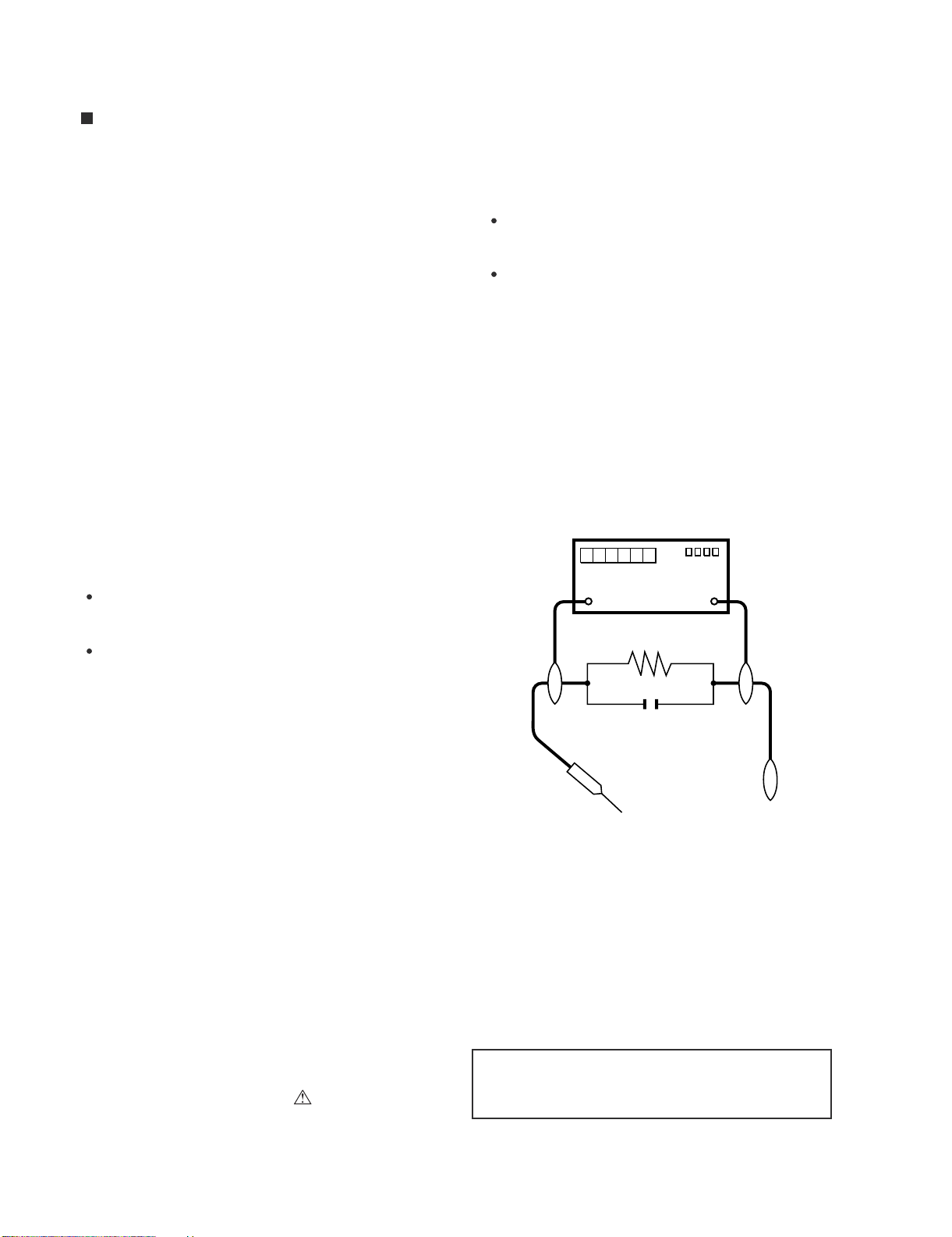
3. S'assurer qu'il n'y ait pas de danger d'électrocution en
vérifiant la fuite de courant, de la facon suivante:
Brancher le cordon d'alimentation directem-ent à une
prise de courant de 120-V. (Ne pas utiliser de tran
sformateur d'isolation pour cet essai).
A l'aide de deux fils à pinces, brancher une résistance
de 1.5 kΩ 10 watts en parallèle avec un condensateur
de 0.15µF en série avec toutes les pièces métalliques
exposées du coffret et une terre connue comme une
conduite électrique ou une prise de terre branchée à la
terre.
Utiliser un voltmètre CA d'une sensibilité d'au moins
5000Ω/V pour mesurer la chute de tension en travers
de la résistance.
Toucher avec la sonde d'essai les pièces métalliques
exposées qui présentent une voie de retour au châssis
(antenne, coffret métallique, tête des vis, arbres de
commande et des boutons, écusson, etc.) et mesurer la
chute de tension CA en-travers de la résistance. Toutes
les vérifications doivent être refaites après avoir inversé
la fiche du cordon d'alimentation. (Si nécessaire, une
prise d'adpatation non polarisée peut être utilisée dans
le but de terminer ces vérifications.)
La tension de pointe mesurèe ne doit pas dépasser 0.4V
(correspondante au courant CA de pointe de 0.27mA).
Dans le cas contraire, ilyaunepossibilité de choc
électrique qui doit être supprimée avant de rendre le
récepteur au client.
DVM
ECHELLE CA
1.5k ohm
10W
0.15
µ
SONDE D'ESSAI
F
AUX PIECES
METALLIQUES
EXPOSEES
BRANCHER A UNE
TERRE CONNUE
/////////////////////////////////////////////////////////////////////////////////////////////////////////////////////////////////////////////////////
AVIS POUR LA SECURITE
De nombreuses pièces, électriques et mécaniques, dans
les projecteur à DMD™ présentent des caractéristiques
spéciales relatives à la sécurité, qui ne sont souvent pas
évidentes à vue.
Le degré de protection ne peut pas être nécessairement
augmentée en utilisant des pièces de remplacement
étalonnées pour haute tension, puissance, etc.
Les pièces de remplacement qui présentent ces
caractéristiques sont identifiées dans ce manuel;
les pièces électriques qui présentent ces particularités
sont identifiées par la marque “ ” et hachurées dans la
/////////////////////////////////////////////////////////////////////////////////////////////////////////////////////////////////////////////////////
liste des pièces de remplacement et les diagrammes
schématiques. Pour assurer la protection, ces pièces
doivent être identiques à celles utilisées dans le circuit
d’origine. L’utilisation de pièces qui n’ont pas les mêmes
caractéristiques que les pièces recommandées par l’usine,
indiquées dans ce manuel, peut provoquer des
électrocutions, incendies ou autres accidents.
AVERTISSEMENT: La composante bimétallique dispose du
conducteur primaire dénudé. Faire attention
lors de la manipulation de cette
composante sous tension.
ii
Page 4
XG-PH70X/XG-PH70X-N (1st. Edition)
NOTE TO SERVICE
PERSONNEL
//////////////////////////////////////////////////////////////
UV-RADIATION PRECAUTION
//////////////////////////////////////////////////////////////
The light source, lamp, in the pr ojector emits small
amounts of UV-Radiation.
AVOID DIRECT EYE AND SKIN EXPOSURE.
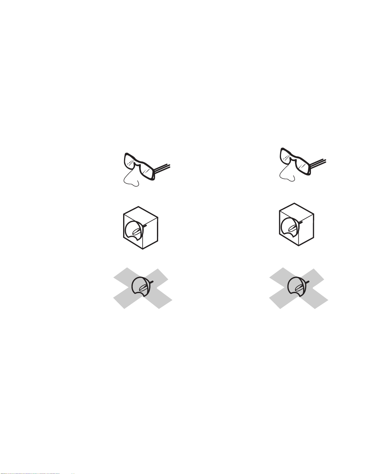
To ensure safety please adhere to the following:
1. Be sure to wear sun-glasses when servicing the
projector with the lamp
turned “on” and the top
enclosure removed.
2. Do not operate the lamp outside of the lamp housing.
NOTE POUR LE PERSONNEL
D'ENTRETIEN
//////////////////////////////////////////////////////////////
PRECAUTION POUR LES RADIATIONS UV
//////////////////////////////////////////////////////////////
La source de lumière, la lampe, dans le projecteur émet
de petites quantités de radiation UV.
EVITEZ TOUTE EXPOSITION DIRECTE DES
YEUX ET DE LA PEAU.
Pour votre sécurité, nous vous prions de respecter
les points suivants:
Toujours porter des lunettes de soleil lors d’un entretien
1.
du projecteur
avec la lampe allumée
et le haut du coffret retiré.
2. Ne pas faire fonctionner la lampe à l’extérieur du boîtier
de lampe.
3. Do not operate for more than 2 hours with the enclosure
removed.
UV-Radiation and Medium Pressure
Lamp Precautions
1. Be sure to disconnect the AC plug when replacing the
lamp.
2. Allow one hour for the unit to cool down before
servicing.
3. Replace only with same type lamp. Type AN-PH7LP1/
AN-PH7LP2 rated 260W.
4. The lamp emits small amounts of UV-Radiation, avoid
direct-eye contact.
5. The medium pressure lamp involves a risk of explosion.
Be sure to follow installation instructions described
below and handle the lamp with care.
3. Ne pas faire fonctionner plus de 2 heures avec le coffret
retiré.
Précautions pour les radiations UV
et la lampe moyenne pression
1. Toujours débrancher la fiche AC lors du remplacement
de la lampe.
2. Laisser l'unité refroidir pendant une heure avant de
procéder à l'entretien.
3. Ne remplacer qu'avec une lampe du même type. Type
AN-PH7LP1/AN-PH7LP2, caractéristique 260W.
4. La lampe émet de petites quantités de radiation UVéviter tout contact direct avec les yeux.
5. La lampe moyenne pression implique un risque
d'explosion. Toujours suivre les instructions
d'installation décrites ci-dessous et manipuler la lampe
avec soin.
iii
Page 5
XG-PH70X/XG-PH70X-N (1st. Edition)
////////////////////////////////////////////////////////////////
UV-RADIATION PRECAUTION (Continued)
////////////////////////////////////////////////////////////////
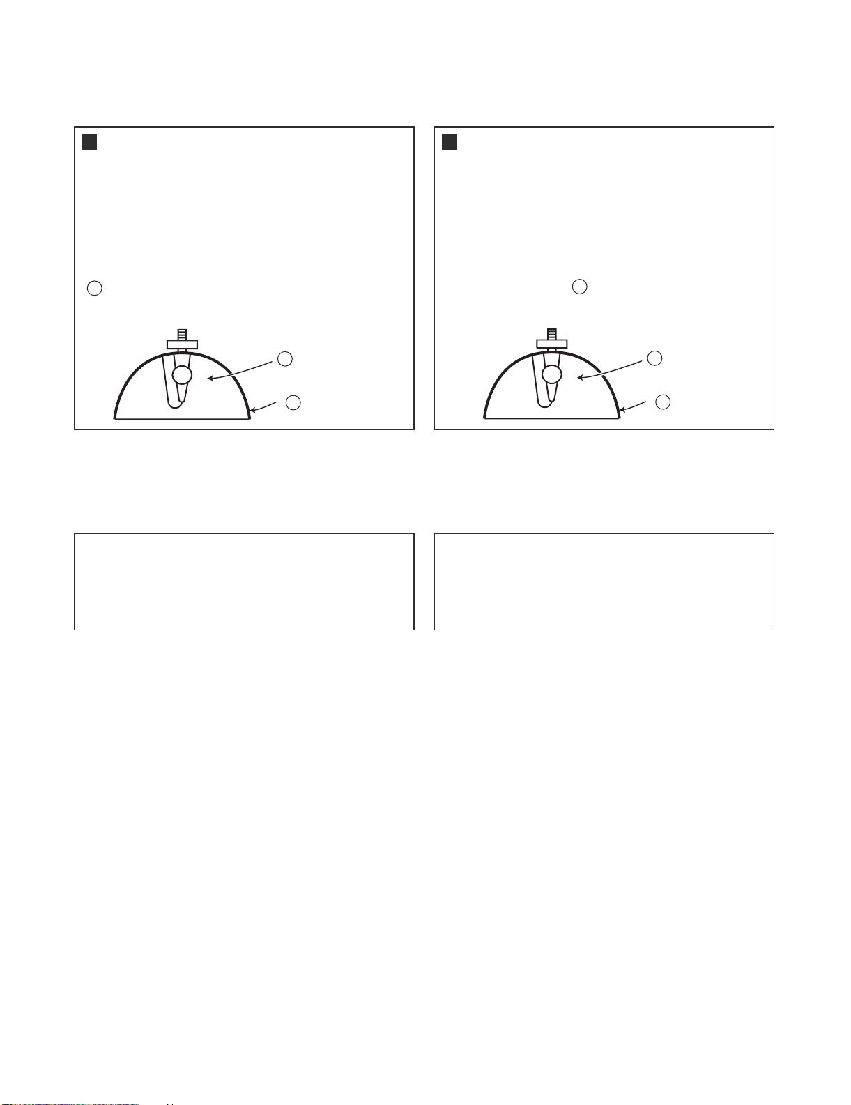
Lamp Replacement
Note:
Since the lamp reaches a very high temperature during
units operation replacement of the lamp should be
done at least one hour after the power has been turned
off. (to allow the lamp to cool off.)
Installing the new lamp, make sure not to touch the
lamp (bulb) replace the lamp by holding its reflector
2
.
[Use original replacement only.]
Lamp
1
Reflector
2
DANGER ! –– Never turn the power on without the
lamp to avoid electric-shock or damage of the devices
since the stabilizer generates high voltages at its start.
////////////////////////////////////////////////////////////////
PRECAUTION POUR LES RADIA TIONS UV (Suite)
////////////////////////////////////////////////////////////////
Remplacement de la lampe
Remarque:
Comme la lampe devient très chaude pendant le
fonctionnement de l’unité, son remplacement ne doit
être effectué au moins une heure après avoir coupé
l’alimentation (pour permettre à la lampe de refroidir).
En installant la nouvelle lampe, s’assurer de ne pas
toucher la lampe (ampoule). Remplacer la lampe en
tenant son réflecteur .
[N’utiliser qu’un remplacement d’origine.]
DANGER ! –– Ne jamais mettre sous tension sans la
lampe pour éviter un choc électrique ou des
dommages des appareils car le stabilisateur génère
de hautes tensions à sa mise en route.
2
1
Lampe
2
Reflecteur
Since small amounts of UV-radiation are emitted
from an opening between the exhaust fans, it is recommended to place the cap of the optional lens on
the opening during servicing to avoid eye and skin
exposure.
Comme de petites quantités de radiation UV sont
émises par une ouverture entre les ventilateurs aspirants, il est recommandé de placer le capuchon de
l’optique optionnelle sur l’ouverture pendant l’entretien
pour éviter une exposition des yeux et la peau.
iv
Page 6
XG-PH70X/XG-PH70X-N (1st. Edition)
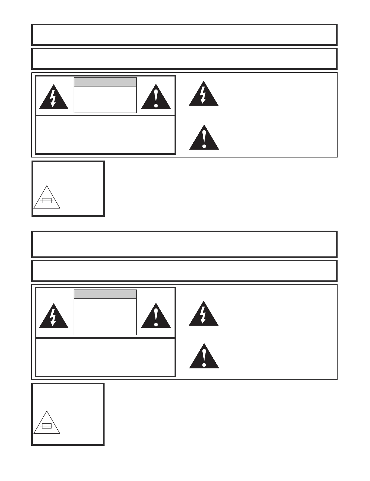
WARNING: High brightness light source, do not stare into the beam of light, or view directly. Be especially
careful that
children do not stare directly in to the beam of light.
WARNING: TO REDUCE THE RISK OF FIRE OR ELECTRIC SHOCK, DO N OT EXPOSE
THIS UNIT TO
MOISTURE OR WET LOCATIONS.
CAUTION
RISK OF ELECTRIC SHOCK.
DO NOT REMOVE SCREWS
EXCEPT SPECIFIED USER
SERVICE SCREW.
CAUTION: TO REDUCE THE RISK OF ELECTRIC SHOCK,
DO NOT REMOVE CABINET.
NO USER-SERVICEABLE PARTS EXCEPT LAMP UNIT.
REFER SERVICING TO QUALIFIED SERVICE
PERSONNEL.
The lighting flash with arrowhead within a
triangle is intended to tell the user that
parts inside the product are risk of electric
shock to persons.
The exclamation point within a triangle is
intended to tell the user that important
operating and servicing instructions are in
the manual with the projector.
CAUTION
(FILTER Unit)
8A 250V
For continued
protection against a
risk of fire, replace
only with same type
8A, AC250V fuse.
(F301)
//////////////////////////////////////////////////////////////////////////////////////////////////////////////////////////////////
AVERTISSEMENT: Source lumineuse de grande intensité. Ne pas fixer le faisceau lumineux ou le regarder
directement. Ve
iller particulièrement à éviter que les enfants ne fixent directement le
faisceau lumineux.
AVERTISSEMENT: AFIN D’EV
ITER TOUT RISQUE D’INCENDIE OU D’ELECTROCUTION, NE PAS PLACER
CET APPAREIL DANS UN ENDROIT HUMIDE OU MOUILLE.
ATTENTION
RISQUE
D’ÉLECTROCUTION. NE
PASR ETIRER LES VIS Á
L’EXCEPTION DE LA VIS DE
REPARATION UTILISATEUR
SPECIFIEES
ATTENTION: POUR EVITER TOUT RISQUE
D’ELECTROCUTION, NE PAS RETIRER LE CAPOT.
AUCUNE DES PIECES INTERIEURES N’EST REPARABLE
PAR L’UTILISATEUR, A L’EXCEPTION DE L’UNITE DE
LAMPE. POUR TOUTE REPARATION, S’ADRESSER A UN
TECHNICIEN D’ENTRETIEN QUALIFIE.
L’éclair terminé d’une flèche à l’intérieur
d’un triangle indique à l’utilisateur que les
pi‘eces se trouvant dans l’appareil sont
susceptibles de provoquer une décharge
électrique.
Le point d’exclamation à l’intérieur d’un
triangle indique à l’utilisateur que les
instructions de fonctionnement et
d’entretien sont détaillées dans les
documents fournis avec le projecteur.
PRECAUTION
(Unité de Filtre)
8A 250V
Pour une protection
continue contre un
risques d’incendie, ne
remplacer qu’avec un
fusible 8A,AC250V
du même type.
(F301)
v
Page 7
XG-PH70X/XG-PH70X-N (1st. Edition)
Precautions for using lead-free solder
Employing lead-free solder
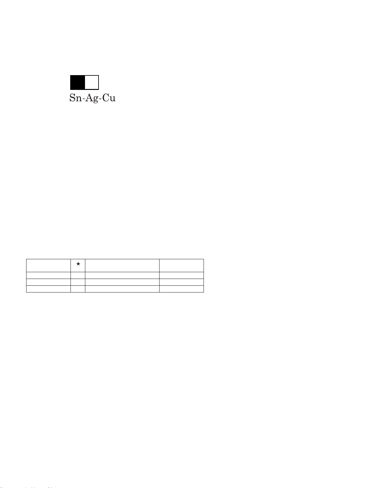
• "PWBs" of this model employs lead-free solder. The LF symbol indicates lead-free solder, and is attached on the PWBs and service manuals. The
alphabetical character following LF shows the type of lead-free solder.
Example:
L Fa
Indicates lead-free solder of tin, silver and copper.
Using lead-free wire solder
• When fixing the PWB soldered with the lead-free solder, apply lead-free wire solder. Repairing with conventional lead wire solder may cause damage or accident due to cracks.
As the melting point of lead-free solder (Sn-Ag-Cu) is higher than the lead wire solder by 40 °C, we recommend you to use a dedicated soldering
bit, if you are not familiar with how to obtain lead-free wire solder or soldering bit, contact our service station or service branch in your area.
Soldering
• As the melting point of lead-free solder (Sn-Ag-Cu) is about 220 °C which is higher than the conventional lead solder by 40 °C, and as it has poor
solder wettability, you may be apt to keep the soldering bit in contact with the PWB for extended period of time. However, Since the land may be
peeled off or the maximum heat-resistance temperature of parts may be exceeded, remove the bit from the PWB as soon as you confirm the
steady soldering condition.
Lead-free solder contains more tin, and the end of the soldering bit may be easily corroded. Make sure to turn on and off the power of the bit as
required.
If a different type of solder stays on the tip of the soldering bit, it is alloyed with lead-free solder. Clean the bit after every use of it.
When the tip of the soldering bit is blackened during use, file it with steel wool or fine sandpaper.
• Be careful when replacing parts with polarity indication on the PWB silk.
Lead-free wire solder for servicing
Part No. Description Code
ZHNDAi123250E J φ0.3mm 250g(1roll) BL
ZHNDAi126500E J φ0.6mm 500g(1roll) BK
ZHNDAi12801KE J φ1.0mm 1kg(1roll) BM
vi
Page 8

XG-PH70X/XG-PH70X-N (1st. Edition)
XG-PH70X
CHAPTER 1. OPERATION MANUAL
[1] SPECIFICATIONS
Service Manual
Product type
Model
Video system
Display device
Standard zoom lens
Projection lamp
Component input (INPUT 1)/
output (OUTPUT) signal
Horizontal resolution
Component input (INPUT 2)
signal
RGB input (INPUT 1/2)/output
(OUTPUT) signal
RGB digital input signal (INPUT 3)
Video input signal
(INPUT 4)
S-video input signal
(INPUT 5)
Audio input signal
Audio output signal
(AUDIO OUTPUT 1
−
RS-232C terminal
LAN terminal
Pixel clock
Vertical frequency
Horizontal frequency
Audio output
Speaker system
Rated voltage
Input current
Rated frequency
Power consumption
Power consumption (standby)
Heat dissipation
Operating temperature
Storage temperature
Cabinet
I/R carrier frequency
Dimensions (approx.)
Weight (approx.)
Replacement parts
Multimedia Projector
XG-PH70X (standard zoom lens attached)/XG-PH70X-N (no lens attached)
NTSC3.58/NTSC4.43/PAL/PAL-M/PAL-N/PAL-60/SECAM/
DTV480I /DTV480P/DTV540P/DTV576I/DTV576P/DTV720P/DTV1035I /DTV1080I
0.7" DLP chip x 1
®
No. of dots: 786,432 dots (1,024 [H] x 768 [V])
1.2 x electric zoom/focus lens, F1.8−F2.0, f = 25.6−31.3 mm (standard equipment with XG-PH70X)
260 W x 2
15-pin mini D-sub connector
Y: 1.0 Vp-p, sync negative, 75 Ω terminated
P
B: 0.7 Vp-p, 75 Ω terminated
R: 0.7 Vp-p, 75 Ω terminated
P
750 TV lines (DTV720P)
BNC connector
Y: 1.0 Vp-p, sync negative, 75 Ω terminated
P
B: 0.7 Vp-p, 75 Ω terminated
R: 0.7 Vp-p, 75 Ω terminated
P
15-pin mini D-sub connector, 5 BNC connector: RGB separate/composite sync (TTL)/sync
on green type analog input: 0Ð0.7 Vp-p, positive, 75 Ω terminated
Horizontal sync. signal: TTL level (positive/negative) or composite sync (Apple only)
Vertical sync. signal: Same as above
DVI connector (24-pin), RGB (digital), 250
−
1,000 mV, 50 Ω (Compatible with HDCP)
RCA connector: VIDEO, composite video, 1.0 Vp-p, sync negative, 75 Ω
terminated
4-pin mini DIN connector
Y (luminance signal): 1.0 Vp-p, sync negative, 75 Ω terminated
C (chrominance signal): Burst 0.286 Vp-p, 75 Ω terminated
φ3.5 mm stereo minijack, RCA terminal
0.5 Vrms, more than 22 kΩ
φ3.5 mm minijack
0.5 Vrms, less than 2.2 kΩ
5)
9-pin D-sub connector
8-pin RJ-45 modular connector
12
−
230 MHz
43
−
200 Hz
−
126 kHz
15
3.0 W (stereo)
3.3 cm round x 2
AC 100
−
6.6 A (AC 100 V)
240 V
−
2.7 A (AC 240 V)
50/60 Hz
650 W (when "Eco Mode" is "OFF")/570 W (when "Eco Mode" is "ON") with AC 100 V
620 W (when "Eco Mode" is "OFF")/550 W (when "Eco Mode" is "ON") with AC 240 V
0.8 W (AC 100 V)−1.1 W (AC 240 V) (When "Monitor Out" and "LAN/RS232C" are set to "Disable".)
2,440 BTU/hour (when "Eco Mode" is "OFF")/2,140 BTU/hour (when "Eco Mode" is "ON")
with AC 100 V
2,330 BTU/hour (when "Eco Mode" is "OFF")/2,070 BTU/hour (when "Eco Mode" is "ON")
with AC 240 V
41 F to 104 F (+5 C to +40 C)
−
4 F to 140 F (−20 C to +60 C)
Plastic
38 kHz
5
16
/32"x73/32"x1835/64" (410 (W) x 180 (H) x 471 (D) mm) (main body only)
5
16
/32"x737/64"x1835/64"
(410 (W) x 192.1 (H) x 471 (D) mm) (including adjustment foot
and projecting parts)
XG-PH70X: 32.9 lbs. (14.9 kg)
XG-PH70X-N: 30.3 lbs. (13.7 kg)
Remote control, Power cord for U.S., Canada, etc., Power cord for Europe, except U.K.,
Power cord for U.K., Hong Kong and Singapore, Power cord for Australia, New Zealand and
Oceania, RGB cable
, Remote mouse receiver, Cap for the standard zoom lens, Projector
manual and technical reference CD-ROM, Operation manual
As a part of policy of continuous improvement, SHARP reserves the right to make design
and specification changes for product improvement without prior notice. The performance
specification figures indicated are nominal values of production units. There may be some
deviations from these values in individual units.
1 – 1
Page 9
[2] Operation Manual
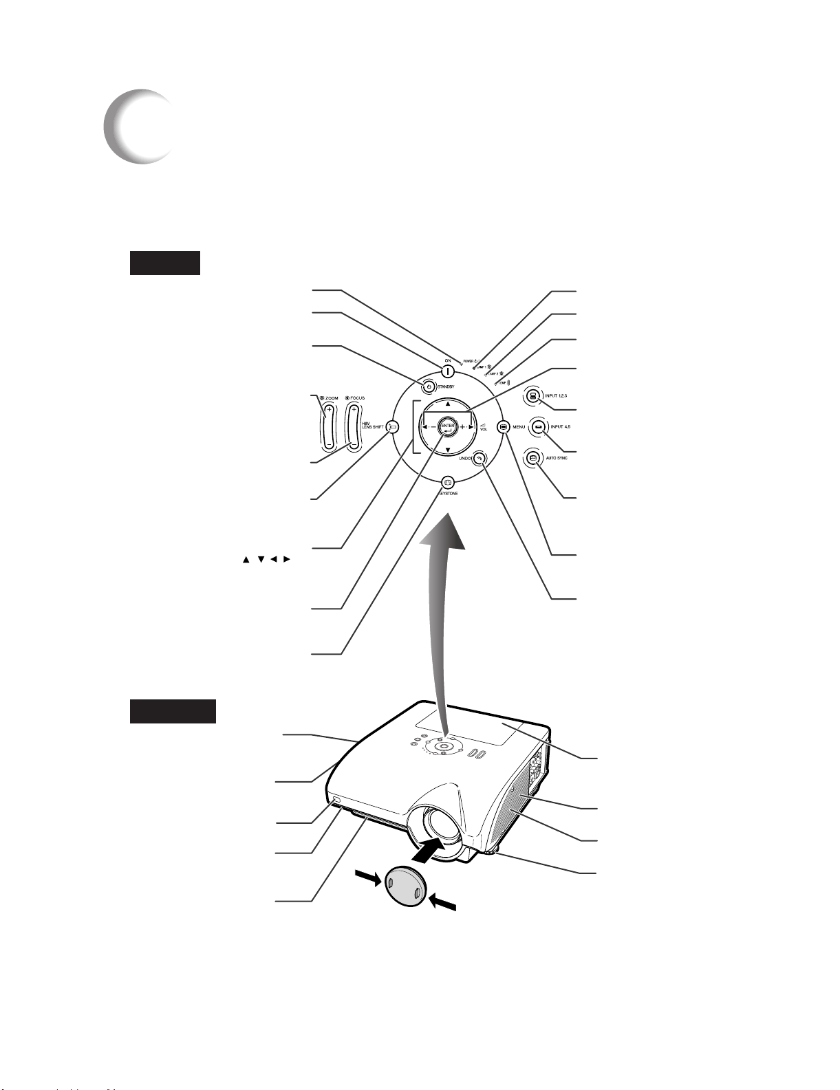
Part Names and Functions
Projector
Top View
XG-PH70X/XG-PH70X-N (1st. Edition)
Power indicator
ON button
For turning the power on.
STANDBY button
For putting the projector
into standby mode.
ZOOM button
For adjusting the projected
image size.
FOCUS button
For adjusting the focus.
H & V LENS SHIFT button
For shifting the lens horizontally
and vertically.
Adjustment buttons
(///)
For selecting menu items
and other settings.
ENTER button
For setting items selected
or adjusted on the menu.
KEYSTONE button
For entering the Keystone
Correction mode.
Lamp indicator 1
Lamp indicator 2
Temperature warning
indicator
Volume buttons
For adjusting the speaker
sound level.
INPUT 1, 2, 3 button
For switching input mode
1, 2 or 3.
INPUT 4, 5 button
For switching input mode
4or5.
AUTO SYNC button
For automatically
adjusting images when
connected to a computer.
MENU button
For displaying adjustment
and setting screens.
UNDO button
For undoing an operation
or returning to the previous
display.
Front View
Carrying handle
Remote control
Adjustment foot
(on the bottom of
For carrying the
projector.
Speaker
sensor
the projector)
Intake vent
Lamp unit cover
Intake vent
Speaker
Adjustment foot
(on the bottom of
the projector)
Attaching the lens cap
Push the lens cap on until it clicks
into position.
Removing the lens cap
Pull the lens cap directly outward.
1 – 2
Page 10
XG-PH70X/XG-PH70X-N (1st. Edition)
Part Names and Functions
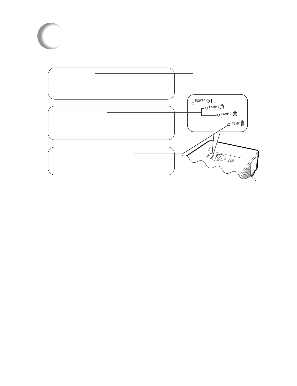
About the Indicators on the Projector
Power indicator
Red on
Green on
Red blinks
Lamp indicators 1, 2
Green on
Green blinks
Red on
Temperature warning indicator
Off
Red blinks/on
...
Normal (Standby)
...
Normal (Power on)
...
The intake vent cover is open.
...
Normal
...
The lamp is warming up.
The lamp has been shut down abnormally or
needs to be changed.
...
The internal temperature is abnormally
high.
...
Normal
...
1 – 3
Page 11
XG-PH70X/XG-PH70X-N (1st. Edition)
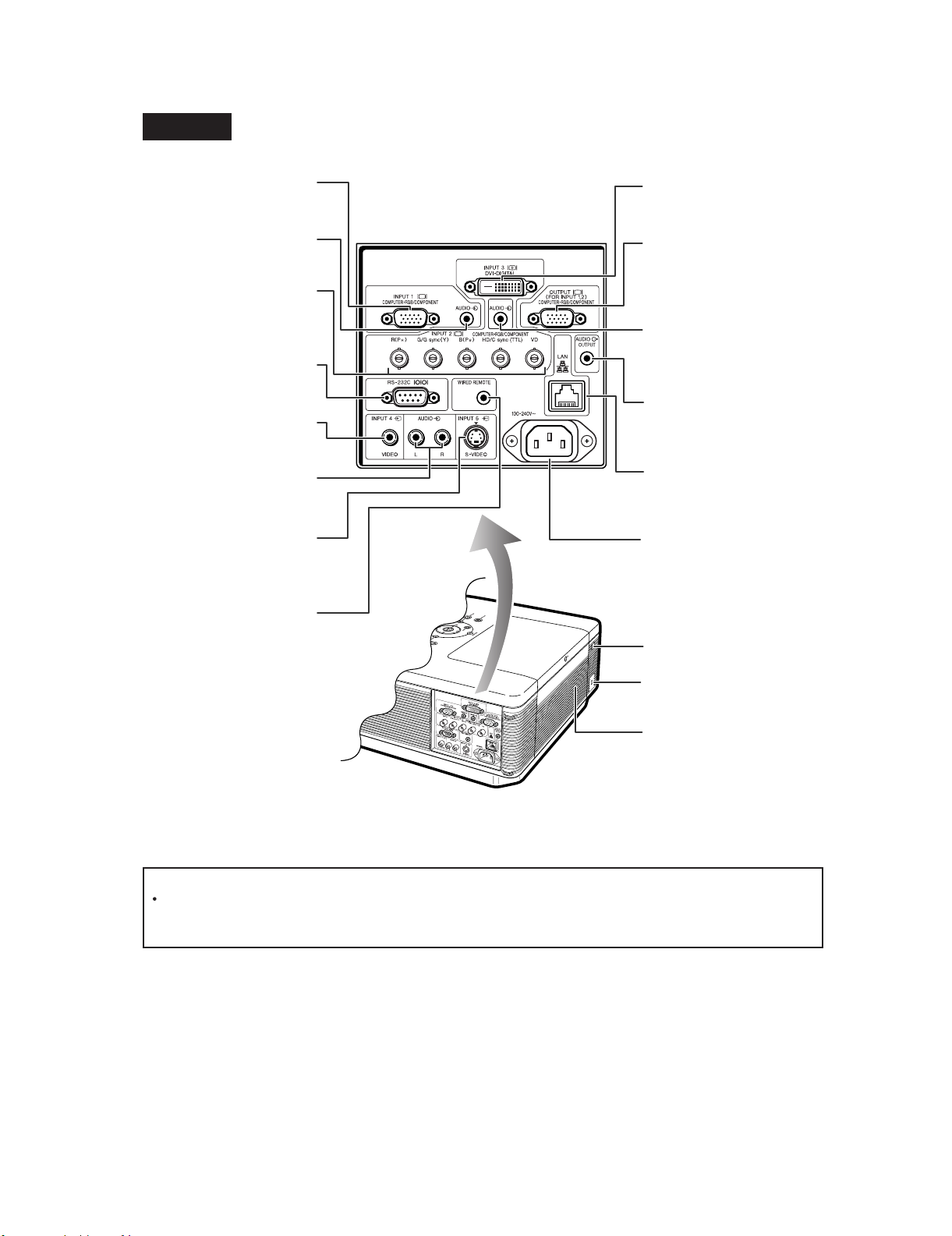
Projector (Side View)
Terminals Refer to "INPUT/OUTPUT Terminals and Connectable Main Equipment" on
INPUT 1 terminal
Terminal for computer RGB
and component signals.
AUDIO input (1) terminal
Audio input terminal for
INPUT 1.
INPUT 2 terminals
BNC terminals for computer
RGB and component
signals.
RS-232C terminal
Terminal for controlling the
projector using a computer.
INPUT 4 terminal
Terminal for connecting
video equipment.
AUDIO input (4, 5) terminals
Shared audio input terminals for
INPUT 4 and 5.
INPUT 5 terminal
Terminal for connecting
video equipment with an
S-video terminal.
WIRED REMOTE terminal
For connecting the remote
control to the projector when
the signals from the remote
control cannot reach the
remote control sensor.
INPUT 3 terminal
Terminal for DVI digital RGB
and digital component signals.
OUTPUT (FOR INPUT 1, 2)
terminal
Output terminal for computer
RGB and component signals.
Shared for INPUT 1 and 2.
AUDIO input (2, 3) terminal
Shared audio input terminal for
INPUT 2 and 3.
AUDIO OUTPUT terminal
Audio output terminal shared
for INPUT 1−5.
LAN terminal
Terminal for controlling the
projector using a computer
via network.
AC socket
Connect the supplied Power
cord.
Remote control sensor
Kensington Security
Standard connector
Exhaust vent
The speed and pitch of
the cooling fan may
change during operation
in response to internal
temperature changes.
This is normal operation
and does not indicate a
malfunction.
Using the Kensington Lock
This projector has a Kensington Security Standard connector for use with a Kensington MicroSaver Security
System. Refer to the information that came with the system for instructions on how to use it to secure the
projector.
1 – 4
Page 12
XG-PH70X/XG-PH70X-N (1st. Edition)
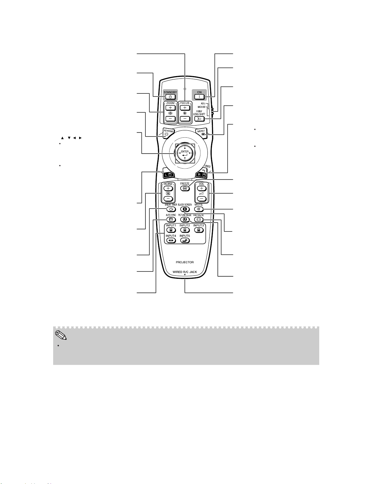
Remote Control
For bringing the projected image
into focus.
STANDBY button
FOCUS buttons
For putting the projector into
standby mode.
ZOOM buttons
For adjusting the projected
image size.
KEYSTONE button
For entering the Keystone
Correction mode.
Mouse/adjustment button
(///)
For moving the computer
cursor while the
ADJ./MOUSE switch is the
MOUSE position.
For selecting menu items
while the ADJ./MOUSE
s
witch is the ADJ. position.
ENTER button
For setting items selected or
adjusted on the menu.
L-click button
For the left click while the
ADJ./MOUSE switch is the
MOUSE position.
ENLARGE (enlarge/reduce)
buttons
For enlarging/reducing part of the
image.
BREAK TIMER button
For setting the break time.
ON button
For turning the power on.
ADJ./MOUSE switch
For switching the remote control
modes.
H & V LENS SHIFT button
For shifting the lens horizontally
and vertically.
MENU button
For displaying adjustment and
setting screens.
R-c
lick/UNDO button
For the right click while the
ADJ./MOUSE switch is the
MOUSE position.
For undoing an operation or
returning to the previous
display while the ADJ./MOUSE
switch is the ADJ. position.
FREEZE button
For freezing images.
Volume buttons
For adjusting the speaker sound level.
MUTE button
For temporarily turning off the
sound.
BLA
CK SCREEN button
For temporarily display the black
screen.
RESIZE button
F
or switching the screen size.
For automatically adjusting images
AUTO SYNC button
when connected to a computer.
INPUT 1, 2, 3, 4 and 5 buttons
For switching to the respective
input modes.
PICTURE MODE button
For switching the picture mode.
WIRED R/C JACK
For connecting the remote control
to the projector when the signals
from the remote control cannot
reach the remote control sensor.
Note
All the buttons on the remote control, except the mouse/adjustment button and the ADJ./MOUSE switch,
are made of luminous material that is visible in the dark. Visibility will diminish over time. Exposure to light
will recharge the luminous buttons.
1 – 5
Page 13
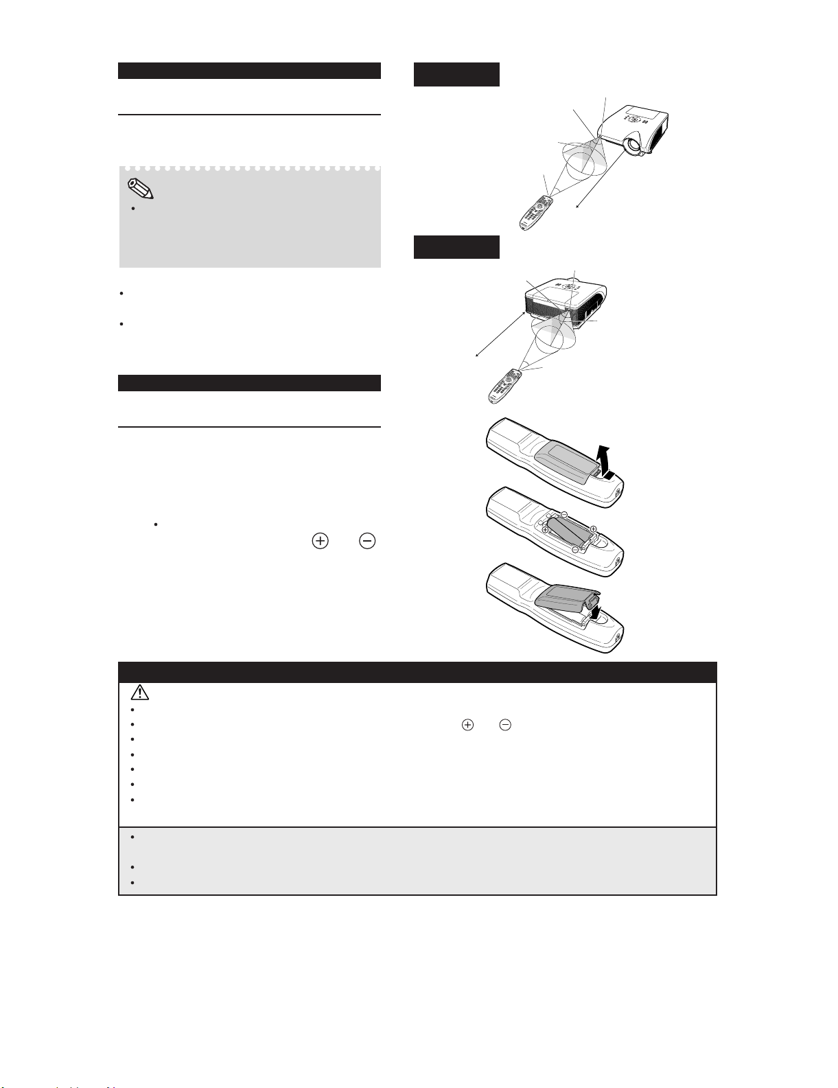
Usable Range
The remote control can be used to control the
projector within the ranges shown in the illustration.
Note
The signal from the remote control can be reflected off a screen for easy operation. However, the effective distance of the signal may
differ depending on the screen material.
When using the remote control:
Ensure that you do not drop it or expose it to
moisture or high temperature.
The remote control may malfunction under a
fluorescent lamp. In this case, move the projector away from the fluorescent lamp.
Inserting the Batteries
Front View
Remote control
signal transmitters
Rear View
23' (7 m)
XG-PH70X/XG-PH70X-N (1st. Edition)
Remote control sensor
30°
30°
30°
Remote control
Remote control sensor
30°
30°
Remote control
signal transmitters
Remote control
23' (7 m)
30°
1
Press the tab and lift open the battery
cover in the direction of the arrow
2
Insert the batteries.
Insert the batteries making sure the polarities correctly match the
marks inside the battery compartment.
3
Insert the tabs on the end of the
.
and
battery cover into their slots and
press the cover into position.
Incorrect use of the batteries may cause them to leak or explode. Please follow the precautions below.
Caution
Danger of explosion if battery is incorrectly replaced. Replace only with the same or equivalent type.
Insert the batteries making sure the polarities correctly match the
Batteries of different types have different properties, therefore do not mix batteries of different types.
Do not mix new and old batteries.
This may shorten the life of new batteries or may cause old batteries to leak.
Remove the batteries from the remote control once they have run out, as leaving them in can cause them to leak.
Battery fluid from leaked batteries is harmful to skin, therefore ensure you wipe them first and then remove them
using a cloth.
The batteries included with this projector may run down in a short period, depending on how they are kept.
Be sure to replace them as soon as possible with new batteries.
Remove the batteries from the remote control if you will not be using the remote control for a long time.
Comply with the rules (ordinance) of each local government when disposing of worn-out batteries.
and marks inside the battery compartment.
1 – 6
Page 14
XG-PH70X/XG-PH70X-N (1st. Edition)
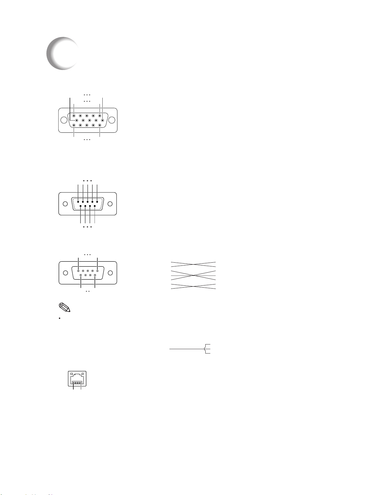
Connecting Pin Assignments
RGB Signal Terminal (INPUT 1 and OUTPUT (FOR INPUT 1, 2)): 15-pin mini D-sub female connector
10
5
15
RS-232C Terminal: 9-pin D-sub male connector
6
1
11
Pin No. Signal Name I/O Reference
51
RGB Input
1. Video input (red)
2. Video input (green/sync on green)
3. Video input (blue)
4. Not connected
5. Not connected
6. Earth (red)
7. Earth (green/sync on green)
8. Earth (blue)
9. Not connected
10. GND
11. Not connected
12. Bi-directional data
13. Horizontal sync signal: TTL level
14. Vertical sync signal: TTL level
15. Data clock
1 Not connected
2 RD Receive Data Input Connected to internal circuit
3 SD Send Data Output Connected to internal circuit
4 Not connected
5 SG Signal Ground Connected to internal circuit
6 Not connected
7 RS Request to Send Connected to CS in internal circuit
8 CS Clear to Send Connected to RS in internal circuit
9 Not connected
Component Input
10. Not connected
11. Not connected
12. Not connected
13. Not connected
14. Not connected
15. Not connected
)
1. P
R(CR
2. Y
3. P
)
B(CB
4. Not connected
5. Not connected
6. Earth (P
7. Earth (Y)
8. Earth (P
9. Not connected
R
B
)
)
96
RS-232C Cable Recommended Connection: 9-pin D-sub female connector
51
96
Pin No. Signal Pin No. Signal
1CD 1 CD
2RD 2 RD
3SD 3 SD
4ER 4 ER
5SG 5 SG
6DR 6 DR
7RS 7 RS
8CS 8 CS
9CI 9 CI
Note
Depending on the controlling device used, it may be necessary to connect Pin 4 and Pin 6 on the controlling
device (e.g. computer).
Projector
Pin No.
4
5
6
Computer
Pin No.
4
5
6
LAN Terminal : 8-pin RJ-45 modular connector
Pin No. Signal Pin No. Signal
1TX+ 5
2TX− 6RX−
3RX+ 7
8...1
48
1 – 7
Page 15

DVI digital Terminal (INPUT 3)
1724
8
16
1
9
Pin No. Signal
1 T.M.D.S. Data 2-
2 T.M.D.S. Data 2+
3 T.M.D.S. Data 2 Shield
4 Not connected
5 Not connected
6 DDC Clock
7 DDC Data
8 Not connected
9 T.M.D.S. Data 1
10 T.M.D.S. Data 1+
11 T.M.D.S. Data 1 Shield
12 Not connected
13 Not connected
14 +5 V Power
15 Ground
16 Hot Plug Detect
XG-PH70X/XG-PH70X-N (1st. Edition)
Pin No. Signal
17 T.M.D.S. Data 0-
18 T.M.D.S. Data 0+
19 T.M.D.S. Data 0 Shield
20 Not connected
21 Not connected
22 T.M.D.S. Clock Shield
23 T.M.D.S. Clock+
-
24 T.M.D.S. Clock
-
1 – 8
Page 16
XG-PH70X/XG-PH70X-N (1st. Edition)
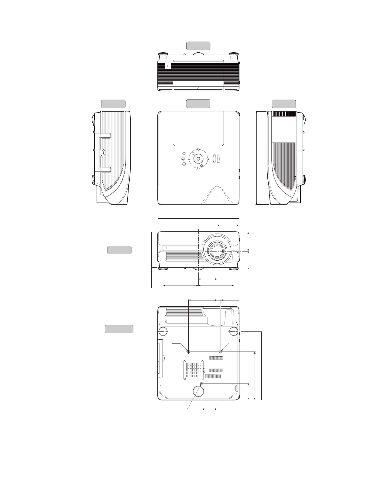
[3] DIMENSIONS
Units: inches (mm)
Side View Side View
Rear View
Top View
165/32(410)
11
4
/32(110.1)
/64 (471)
35
18
Front View
Bottom View
/32 (180)
3
7
/64 (12.1)
31
/64 (97.8)3
55
3
/32 (94.3)
23
3
3
/4(94.9)
1
7
/16(179)71/16(179)
547/64(145.5)
M4
M4
(77.27)
45
/64(17.5)
M4
/8 (346)
5
13
/64 (243.9)
39
9
/64 (85)
23
3
/
64
3
3
1 – 9
Page 17
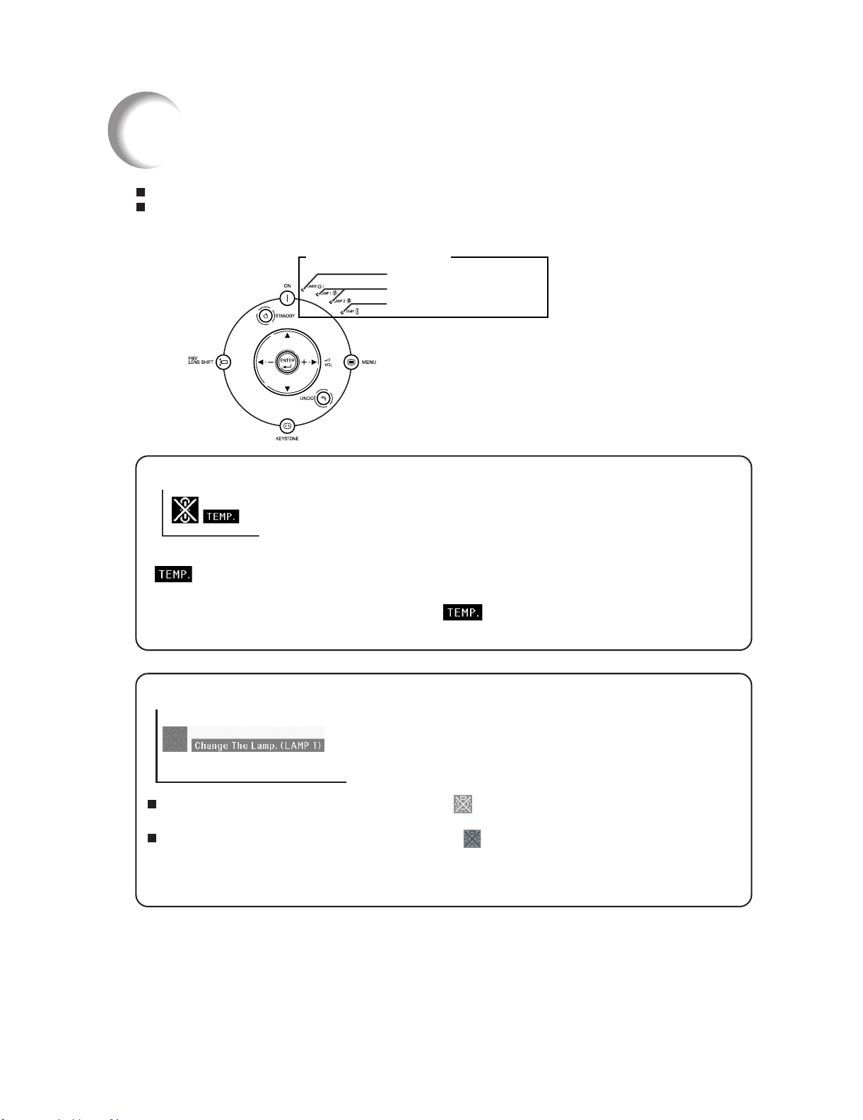
[4] Maintenance Indicators
Maintenance Indicators
The warning lights on the projector indicate problems inside the projector.
If a problem occurs, either the temperature warning indicator or the lamp indicator will illuminate
red, and the projector will enter the standby mode. After the projector has entered the standby
mode, follow the procedures given below.
XG-PH70X/XG-PH70X-N (1st. Edition)
Maintenance Indicators
Power indicator
Lamp indicators 1, 2
Temperature warning indicator
About the temperature warning indicator
If the temperature inside the projector increases, due to blockage of the air vents, or the setting location,
"
turn off and the temperature warning indicator will blink, the cooling fan will run for a further 90 seconds, and
then the projector will enter the standby mode. After "
" will illuminate in the lower left corner of the picture. If the temperature keeps on rising, the lamp will
" appears, ensure you perform the measures
About the lamp indicator
"Change The Lamp. (LAMP 2)" is displayed when the remaining life of the lamp 2 becomes 5% or less.
ı When the remaining lamp life becomes 5% or less,"
will be displayed on the screen.
ı When the percentage becomes 0%, it will change to "
this time, the lamp indicator will illuminate in red.
If you try to turn on the projector a fourth time without replacing the lamp, the lamp whose life is 0%
will not light up.
" (yellow) and "Change The Lamp. (LAMP 1/2)"
"(red), the lamp will automatically turn off. At
1 – 10
Page 18
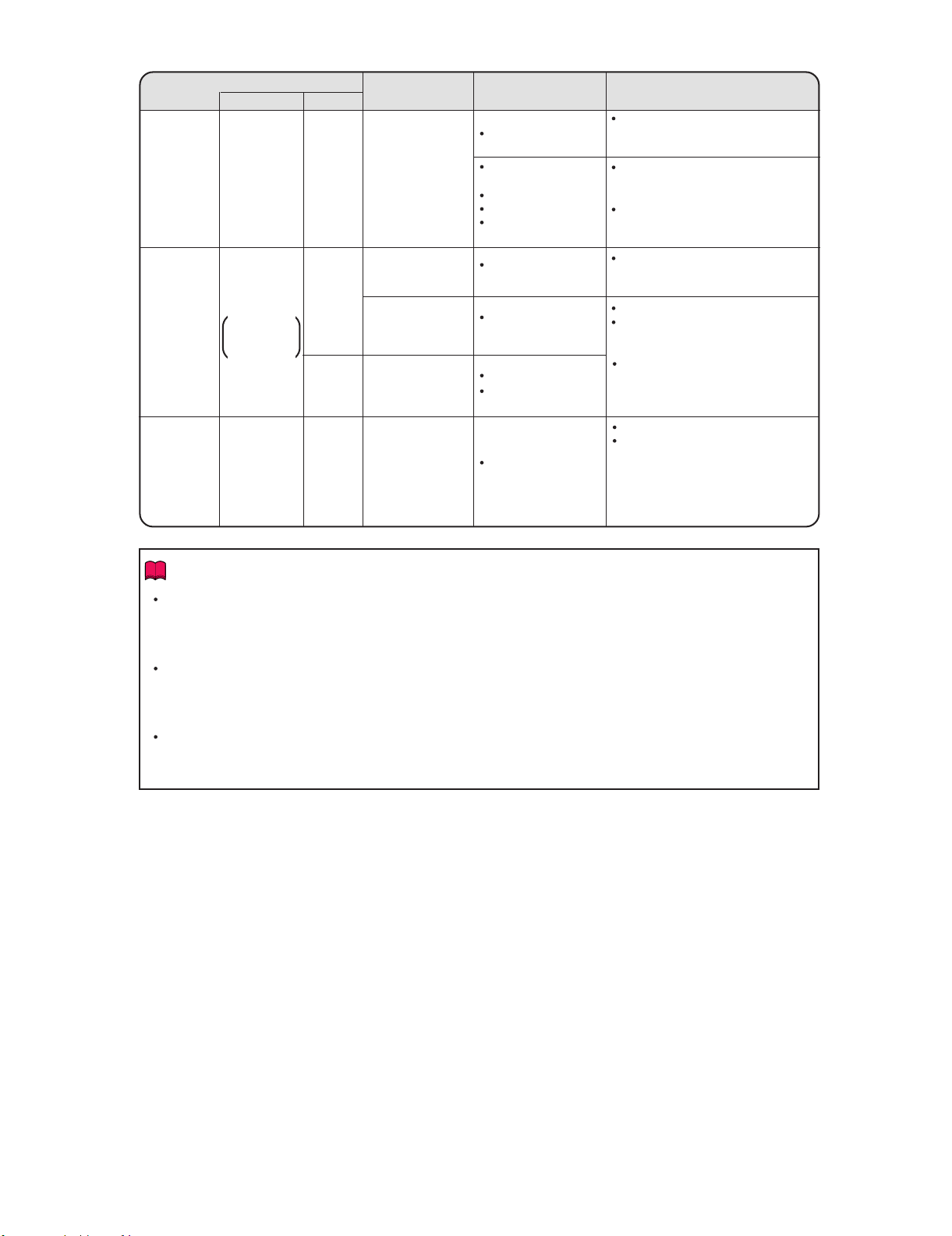
XG-PH70X/XG-PH70X-N (1st. Edition)
Maintenance indicator
Temperature
warning
indicator
Lamp
indicators
1, 2
Power
indicator
Normal
Off
Green on
Green blinks
when the lamp
is warming up.
Green on/
Red on
Abnormal
Red on
(Standby)
Red on
Red on
(Standby)
Red
blinks
Problem
The internal
temperature is
abnormally high.
The lamp does
not illuminate.
Time to change
the lamp.
The lamp does
not illuminate.
The power
indicator blinks in
redwhenthe
projector is on.
Cause Possible solution
Relocate the projector to an area
Blocked air intake
Cooling fan breakdown
Internal circuit failure
Clogged air intake
Clogged intake vent
cover
The lamp is shut
down abnormally.
Remaining lamp life
becomes 5% or less.
Burnt-out lamp
Lamp circuit failure
The intake vent
cover is open.
with proper ventilation.
Take the projector to your nearest
Sharp Authorized Projector Dealer
or Service Center for repair.
Clean the air vents and the intake
vent cover.
Disconnect the power cord from
the AC outlet, and then connect it
again.
Carefully replace the lamp.
Take the projector to your nearest
Sharp Authorized Projector Dealer
or Service Center for repair.
Please exercise care when
replacing the lamp.
Securely install the cover.
If the power indicator blinks even
when the intake vent cover is
securely installed, contact your
nearest Sharp Authorized Projector
Dealer or Service Center for
advice.
Info
If the temperature warning indicator blinks and the projector enters the standby mode, the temperature
warning indicator starts to illuminate. Check whether any of the ventilation holes are blocked
and then try turning the power back on. Wait until the projector has cooled down completely before plugging
in the power cord and turning the power back on. (At least 10 minutes.)
If the power is turned off for a brief moment due to power outage or some other cause while using the
projector, and the power supply recovers immediately after that, the lamp indicator will illuminate in red
and the lamp may not be lit. In this case, unplug the power cord from the AC outlet, replace the power
cord in the AC outlet and then turn the power on again.
The cooling fan keeps the internal temperature of the projector constant and this function is controlled
automatically. The sound of the cooling fan may change during operation because the fan speed may
change and this is not a malfunction.
1 – 11
Page 19
[5] Regarding the Lamp
Regarding the Lamp
Lamp
It is recommended that the lamp units (optional: AN-PH7LP1 and AN-PH7LP2) be replaced when the
remaining lamp life becomes 5% or less, or when you notice a significant deterioration in the picture
and color quality. The lamp life (percentage) can be checked with the on-screen display.
Purchase a replacement lamp unit of type AN-PH7LP1 and AN-PH7LP2 from your place of purchase,
nearest Sharp Authorized Projector Dealer or Service Center.
IMPORTANT NOTE TO U.S. CUSTOMERS:
The lamp included with this projector is backed by a 90-day parts and labor limited warranty. All service
of this projector under warranty, including lamp replacement, must be obtained through a Sharp Authorized Projector Dealer or Service Center. For the name of the nearest Sharp Authorized Projector Dealer
or Service Center, please call toll-free: 1-888-GO-SHARP (1-888-467-4277).
Hg LAMP CONTAINS MERCURY For State Lamp Disposal Information
www.lamprecycle.org or 1-800-BE-SHARP
XG-PH70X/XG-PH70X-N (1st. Edition)
U.S.A. ONLY
Caution Concerning the Lamp
This projector utilizes a pressurized mercury lamp. A loud sound may indicate lamp failure. Lamp
failure can be attributed to numerous sources such as: excessive shock, improper cooling, surface
scratches or deterioration of the lamp due to a lapse of usage time.
The period of time up to failure largely varies depending on the individual lamp and/or the condition
and the frequency of use. It is important to note that failure can often result in the bulb cracking.
When the lamp indicator and on-screen display icon are illuminated, it is recommended that the
lamp be replaced with a new one immediately, even if the lamp appears to be operating normally.
Should the lamp break, the glass particles may spread inside the lamp cage or gas contained in the
lamp may be vented into the room from the exhaust vent. Because the gas in this lamp includes
mercury, ventilate the room well if the lamp breaks and avoid all exposure to the released gas. In
case of exposure to the gas, consult a doctor as soon as possible.
Should the lamp break, there is also a possibility that glass particles may spread inside of the
projector. In such a case, it is recommended you contact your nearest Sharp Authorized Projector
Dealer or Service Center to assure safe operation.
Replacing the Lamp
Caution
Do not remove the lamp unit from the projector right after use. The lamp will be very hot and may cause burn
or injury.
Wait at least one hour after the power cord is disconnected to allow the surface of the lamp unit to fully cool
before removing the lamp unit.
ı Carefully change the lamp by following the instructions described in this section. *If you wish, you
may have the lamp replaced at your nearest Sharp Authorized Projector Dealer or Service Center.
* If the new lamp does not illuminate after replacement, take your projector to the nearest Sharp Authorized
Projector Dealer or Service Center for repair.
1 – 12
Page 20
XG-PH70X/XG-PH70X-N (1st. Edition)
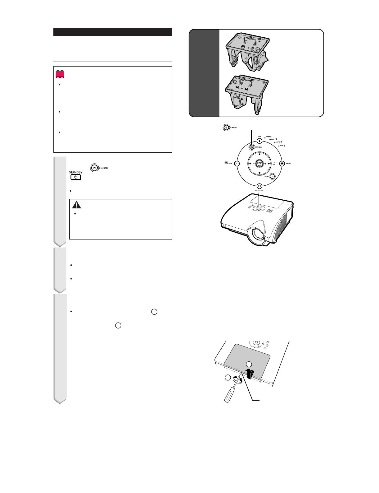
Removing and Installing
the Lamp Unit
Info
Ensure the lamp unit is removed using the
handle. Ensure the glass surface of the
lamp unit or the inside of the projector are
not touched.
To avoid injury to yourself and damage to
the lamp, make sure you carefully follow
the steps below.
Do not loosen other screws except for the
lamp unit cover and lamp unit.
(Only the silver screws are loosened.)
1
Press on the projector or
on the remote control to put
the projector into standby mode.
Wait until the cooling fan stops.
Warning!
Do not remove the lamp unit from the
projector right after use. The lamp and
parts around the lamp will be very hot
and may cause burn or injury.
Lamp unit 1
AN-PH7LP1
Optional
accessories
Lamp unit 2
AN-PH7LP2
STANDBY button
2
Disconnect the power cord.
Unplug the power cord from the AC
socket.
Leave the lamp until it has fully cooled
down (about 1 hour).
3
Remove the lamp unit cover.
Loosen the user service screw ( ) that
secures the lamp unit cover. Remove the
lamp unit cover ( ).
2
1
2
1
User service screw
1 – 13
Page 21
XG-PH70X/XG-PH70X-N (1st. Edition)
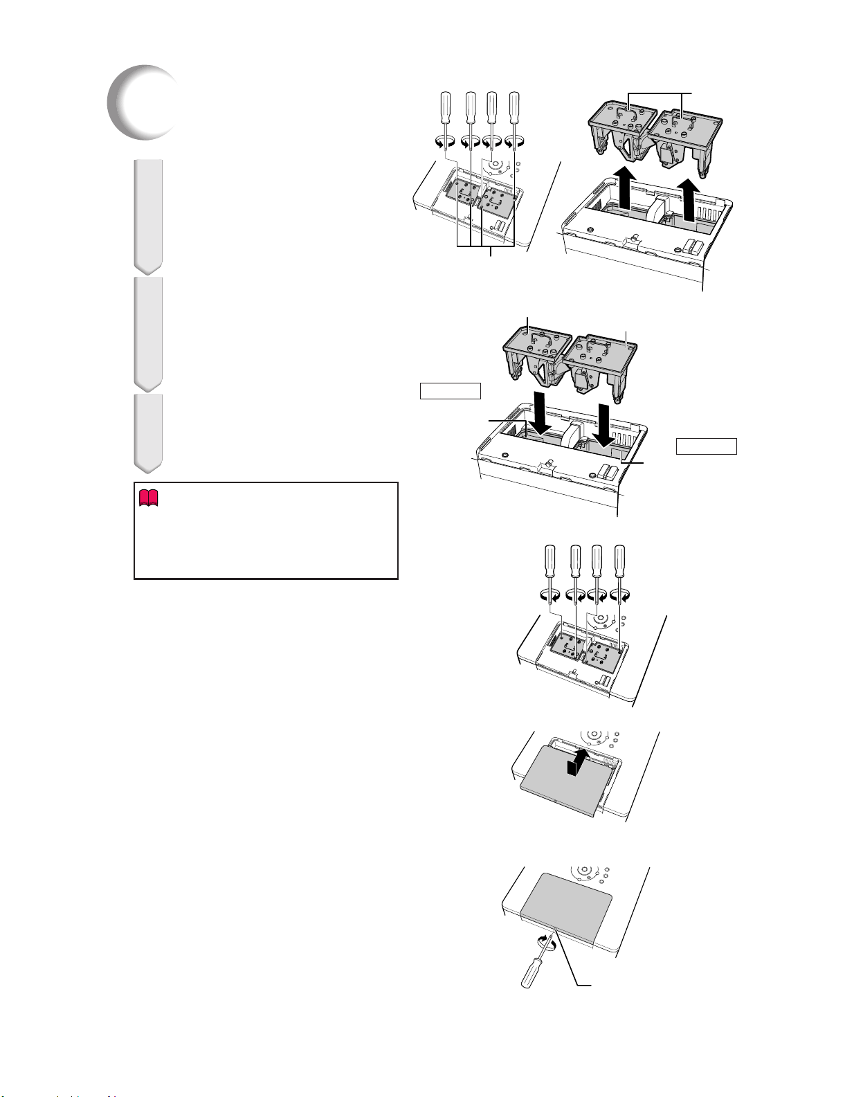
Regarding the Lamp
4
Remove the lamp unit.
Loosen the securing screws (two for
each lamp) from the lamp unit. Hold the
lamp unit by the handle and pull it in the
direction of the arrow. At this time, keep
the lamp unit horizontal and do not tilt it.
5
Insert the new lamp unit.
Press the lamp unit firmly into the lamp
unit compartment. Fasten the securing
screws.
Be sure that AN-PH7LP1 and ANPH7LP2 are respective type.
6
Replace the lamp unit cover.
Align the lamp unit cover and slide it to
close. Then tighten the user service
screw to secure the lamp unit cover.
Info
If the lamp unit and lamp unit cover are not
correctly installed, the power will not turn
on, even if the power cord is connected to
the projector.
Handle
Securing screws
AN-PH7LP1
AN-PH7LP2
For Lamp 1
Compartment for
AN-PH7LP1
For Lamp 2
Compartment for
AN-PH7LP2
1 – 14
User service screw
Page 22
XG-PH70X/XG-PH70X-N (1st. Edition)
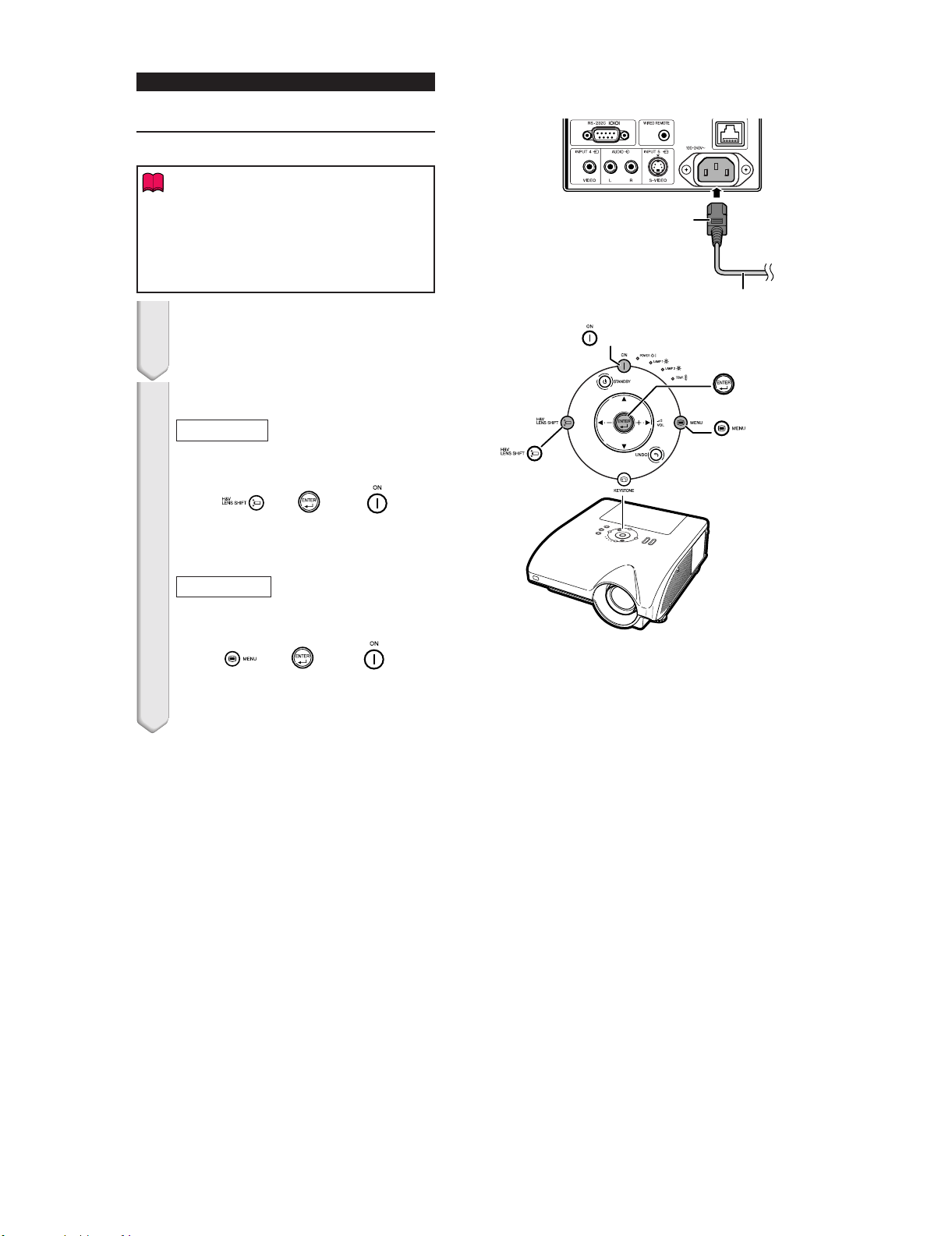
Resetting the Lamp Timer
Reset the lamp timer after replacing the lamp.
Info
Make sure to reset the lamp timer only
when replacing the lamp. If you reset the
lamp timer and continue to use the same
lamp, this may cause the lamp to become
damaged or explode.
1 Connect the power cord.
Plug the power cord into the AC socket
of the projector.
To AC socket
Power cord
ON button
2 Reset the lamp timer.
For Lamp 1
When you reset the timer for ANPH7LP1, while simultaneously holding
down
projector.
"LAMP 1 100%" is displayed, indicating
that the lamp timer is reset.
For Lamp 2
When you reset the timer for ANPH7LP2, while simultaneously holding
down
projector.
"LAMP 2 100%" is displayed, indicating
that the lamp timer is reset.
and , press on the
and , press
ENTER button
MENU button
H&V LENS
SHIFT
button
on the
1 – 15
Page 23
XG-PH70X
CHAPTER 2. REMOVING OF MAJOR PARTS
Service Manual
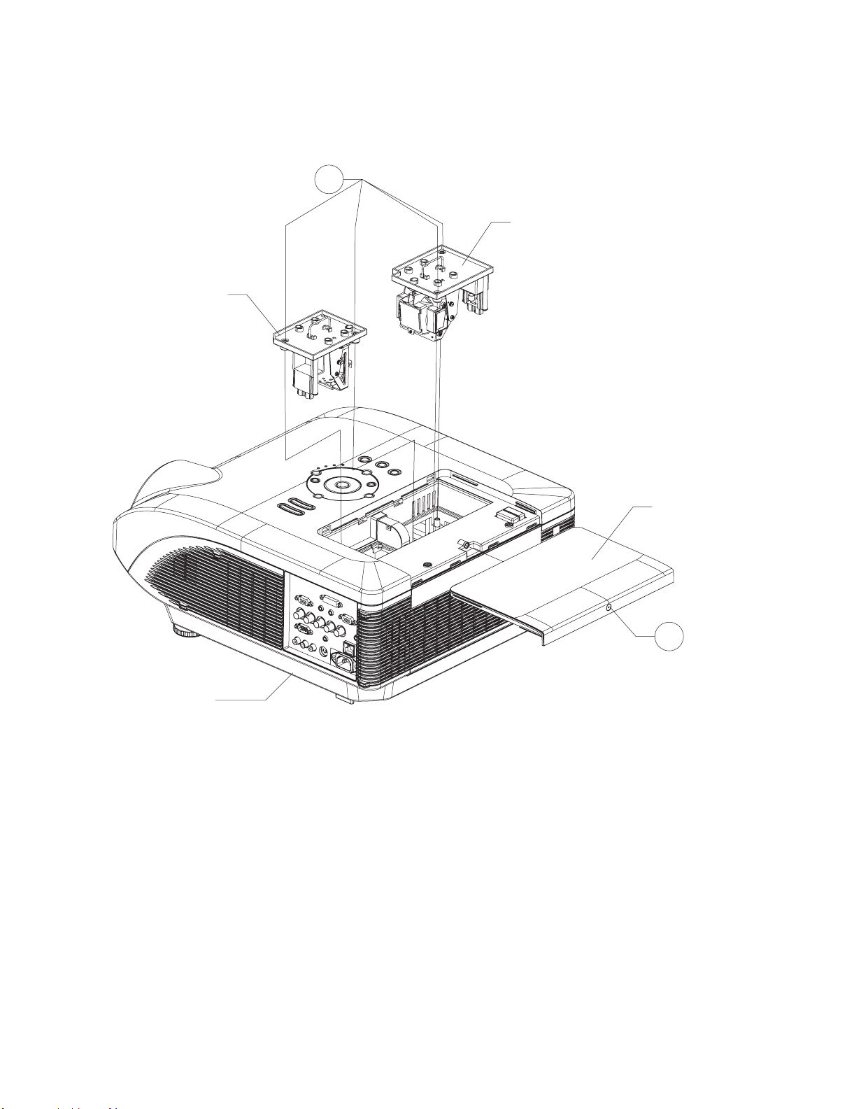
[1] Removing the Lamp Unit
1. Remove the screw from the lamp cover and detach the lamp cover.
2. Remove the four screws from the lamp units and take out the lamp units.
1-2
Lamp Unit 1
XG-PH70X/XG-PH70X-N (1st. Edition)
Lamp Unit 2
Bottom Case
Lamp Cover
1-1
2 – 1
Page 24
XG-PH70X/XG-PH70X-N (1st. Edition)
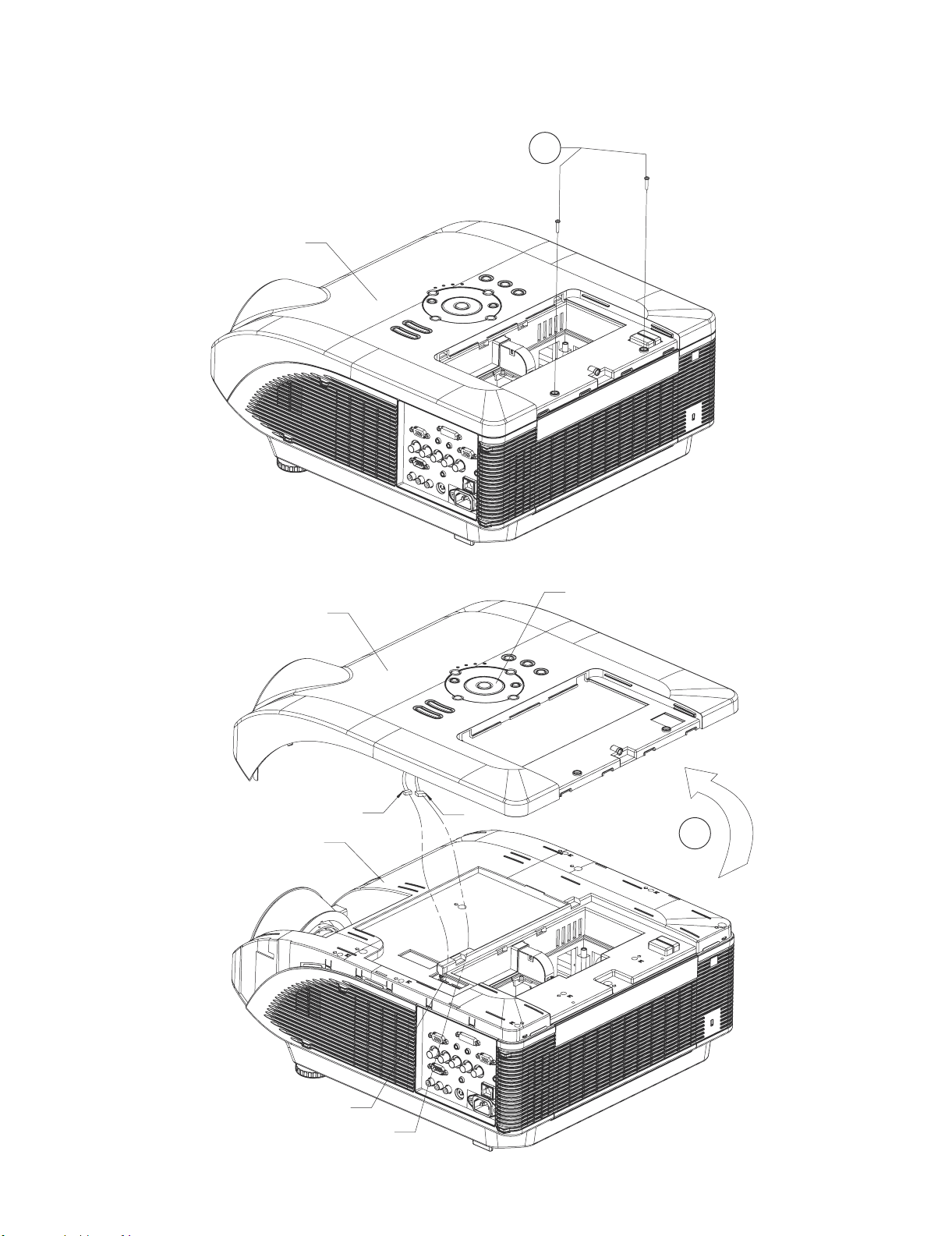
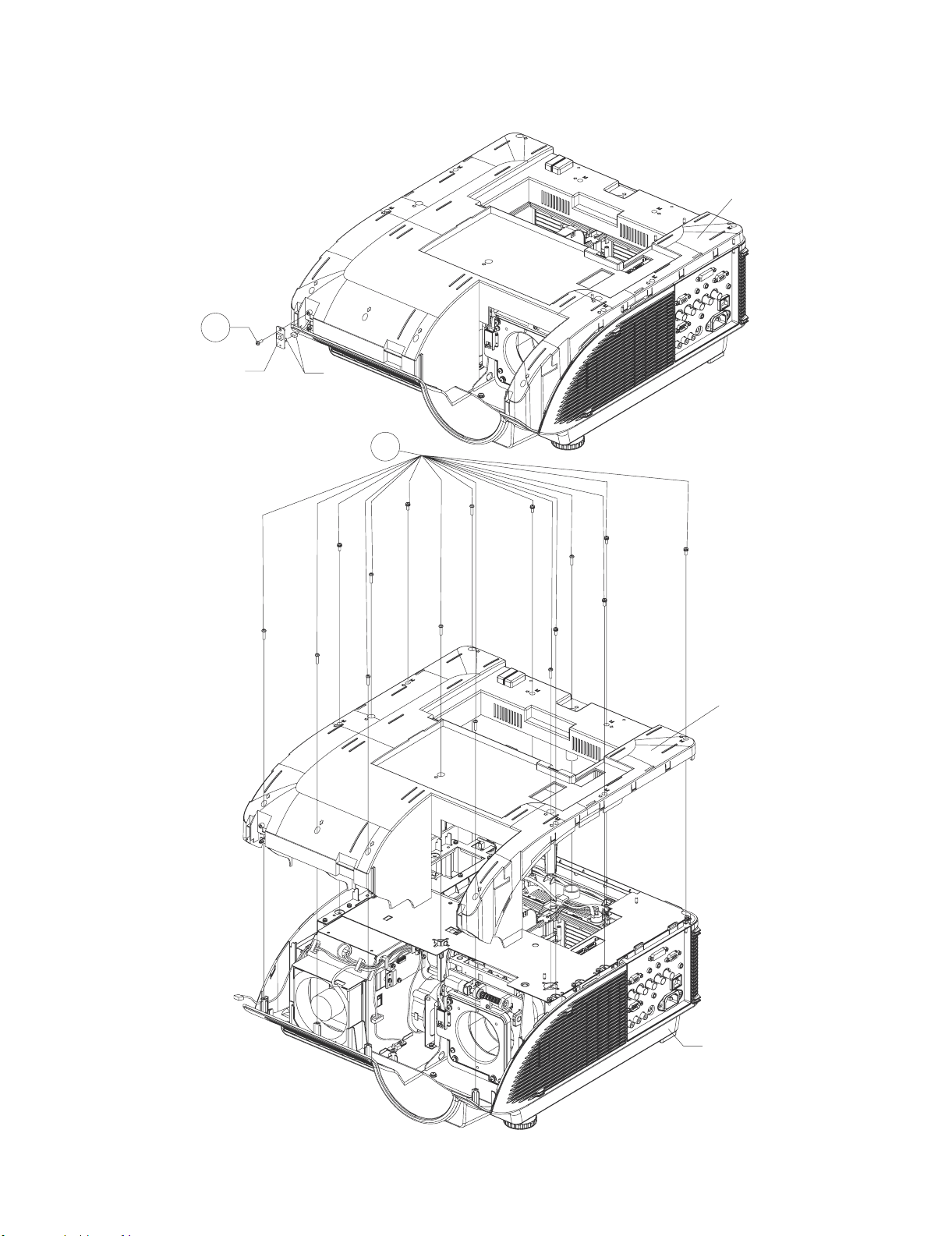
[2] Removing the Top Cover
1. Remove the two screws from the top cover.
2. Slowly lift the back of the top cover and disconnect the operation key connectors (KY1 and KY2). Pull up and off the top cover.
2-1
Top Cover
Top Cover
Top Cabinet
KY1
Operation Key
KY2
2-2
KY1
KY2
2 – 2
Page 25
XG-PH70X/XG-PH70X-N (1st. Edition)
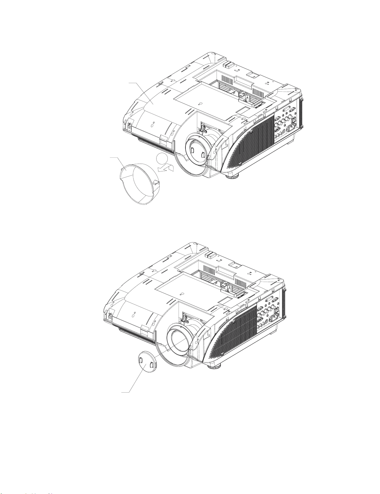
[3] Removing the Lens Hood
* For XG-PH70X-N, the lens removal operations (sections 3 - 6) are unnecessary.
1. Slowly lift the lens hood up until it can be moved forward and then move it forward and detach the lens hood.
Top Cabinet
Lens Hood
[4] Removing the Lens Cap
1. Remove the lens cap.
3-1
Lens Cap
2 – 3
Page 26
XG-PH70X/XG-PH70X-N (1st. Edition)
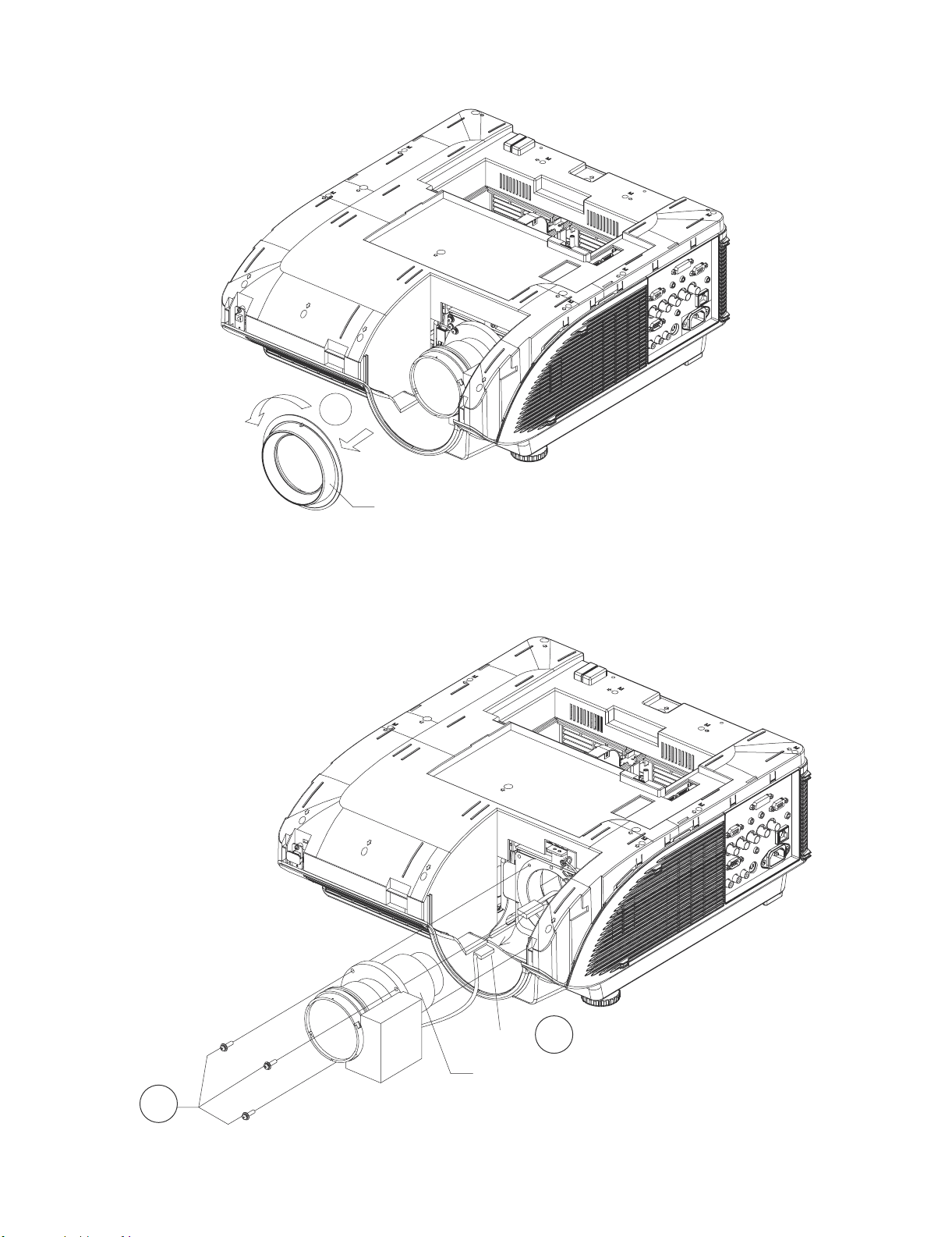
[5] Removing the Lens Trim
1. Rotate the lens trim counterclockwise and then detach the lens trim.
5-1
Lens Trim
[6] Removing the Standard Lens
1. Disconnect the standard lens connector (SL).
2. Remove the three screws from the standard lens and take out the standard lens.
6-2
SL
6-1
Standard Lens
2 – 4
Page 27
XG-PH70X/XG-PH70X-N (1st. Edition)
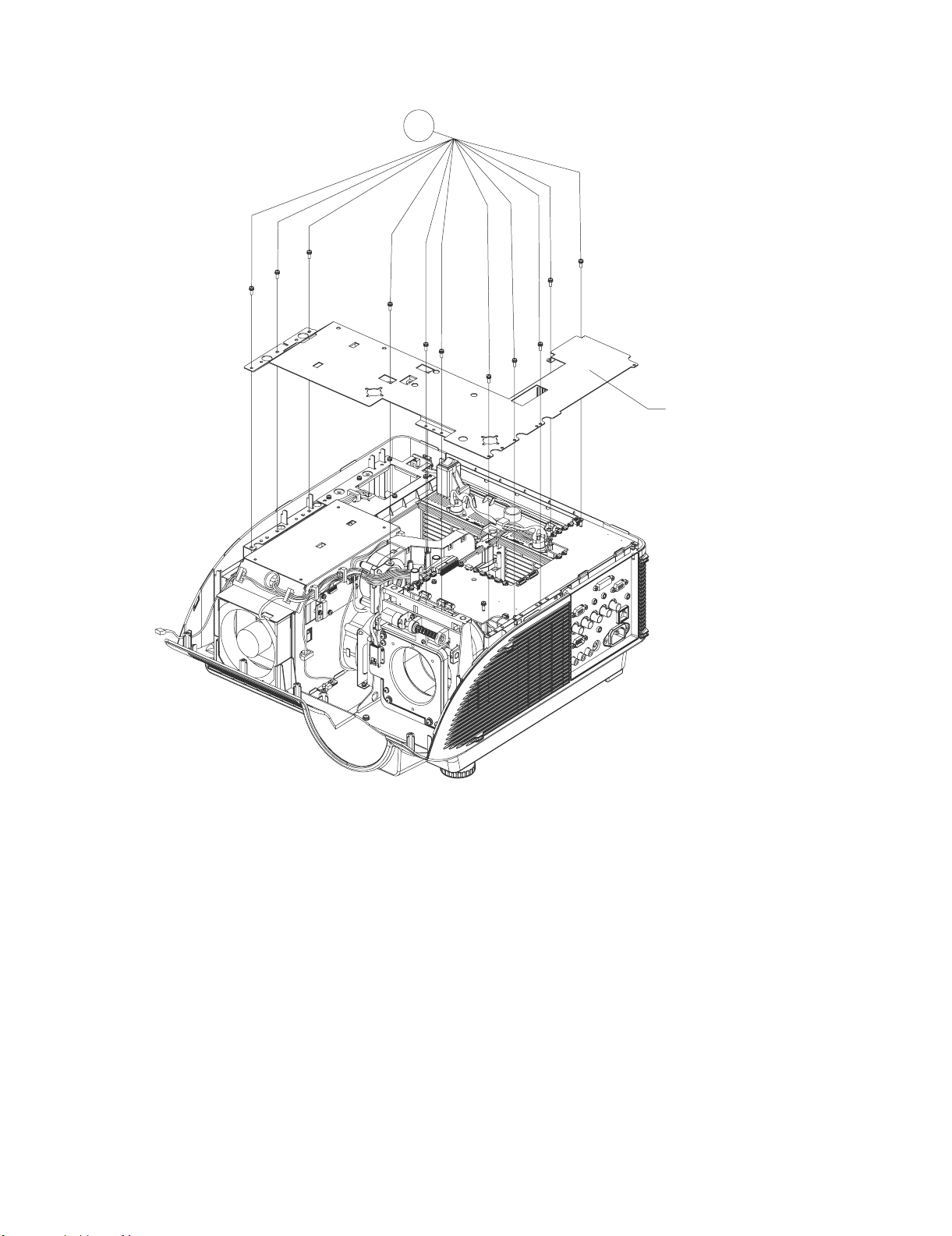
[7] Removing the Top Cabinet
1. Remove the screw from IR (Front) unit, take out the IR (Front) unit and then disconnect the IR (Front) unit connector (RC).
2. Remove the sixteen screws from the top cabinet and then pull up and off the top cabinet.
Top Cabinet
7-1
IR (Front) Unit
RC
7-2
Top Cabinet
2 – 5
Bottom Case
Page 28
XG-PH70X/XG-PH70X-N (1st. Edition)
[8] Removing the Handle Bracket3
1. Remove the Eleven screws from the handle bracket3 and detach the handle bracket3.
8-1
Handle Bracket3
2 – 6
Page 29
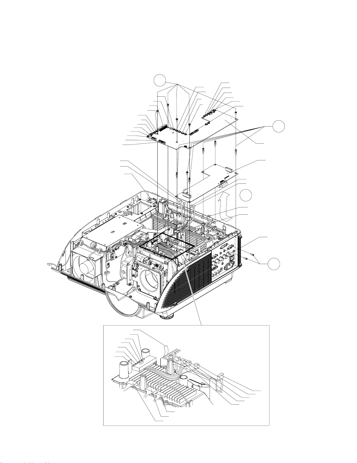
[9] Removing the PWB Units
1. Disconnect all the connector from the Main Unit.
2. Remove the five screws from the Main Unit. Detach the Main Unit from the PC I/F Unit.
3. Remove the two spacers from the PC I/F Unit.
4. Remove the five spacers and the screw.
5. Disconnect the PC I/F Unit from the Terminal Unit and then detach the PC I/F Unit.
XG-PH70X/XG-PH70X-N (1st. Edition)
LSUD
LSRL
LSR
FC4
IR (Rear) Unit
FC1
FR
RC
AD
BTR
TS
BTL
PR
LSF
CW
9-2
FC3
FC5
TS
FC2
LSR
FC6
FC4
FC7
RC
LSL
9-5
LSL
FC6
RC
FC7
9-4
Main Unit
PC I/F Unit
Terminal Unit
RC
FC1
BTR
TS
PR
BTL
CW
FR
LSRL
LSUD
[Enlarged]
LSF
FC3
FC2
FC5
9-3
TS
2 – 7
Page 30
XG-PH70X/XG-PH70X-N (1st. Edition)
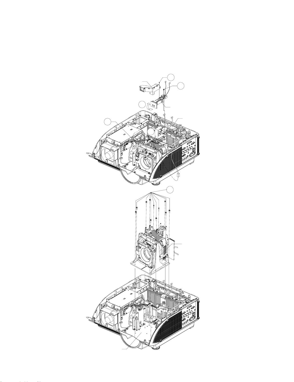
[10] Removing the Optical Engine and Lens Shift
1. Remove the screw from the rod duct and then detach the rod duct.
2. Remove the screw from the lamp channel top.
3. Unhook the front of the lamp channel top and take it out.
4. Slide the bimetal cover and detach it out.
5. Release the cable tie and then disconnect the left speaker connector.
6. Remove the eight screws from the lens shift and remove three screws from the optical engine and then lift the lens shift and optical engine out of
position.
10-5
Rod Duct
10-3
10-1
10-2
Lamp Channel Top
Bimetal Cover
10-4
10-6
Chassis
Lens Shift
2 – 8
Page 31

XG-PH70X/XG-PH70X-N (1st. Edition)
7. Remove the three screws from the optical engine and then lift the optical engine out of position.
10-6
Optical Engine
2 – 9
Page 32

XG-PH70X/XG-PH70X-N (1st. Edition)
[11] Removing the Terminal Unit
1. Remove the four screws from the terminal bracket, lift the terminal bracket and then disconnect the AC socket.
2. Remove the six spacers from the terminal unit.
3. Remove the six screws from the terminal unit and take out the terminal unit.
11-1
11-3
Terminal Unit
Chassis
11-2
Terminal Bracket
2 – 10
Page 33

XG-PH70X/XG-PH70X-N (1st. Edition)
[12] Removing the Filter Unit
1. Disconnect all the connectors from the filter unit. Remove the four screws from the filter unit and then take it out.
12-1
Filter Unit
Chassis
[13] Removing the IR (Rear) Unit
1. Disconnect all the connectors from the power unit. Remove the six screws from the Plate and then take out the Plate.
2. Remove the screw from the IR (Rear) unit and detach the IR (Rear) unit.
3. Remove the four screws from the Direct off unit and then take it out.
14-1
IR (Rear) Unit
14-2
14-1
Direct Off Unit
Power unit
Plate
14-1
PR3
PR2
PR1
PR3
PR2
PR1
Chassis
2 – 11
Page 34

XG-PH70X/XG-PH70X-N (1st. Edition)
[14] Removing the Power Unit and Audio Unit
1. Remove the four screws from the power unit.
2. Detach the power air guide from the power channel upper.
3. Remove the four screws from the power channel down and then disconnect the two power connector PR.
4. Remove the four screws from the power unit and then take out the power unit.
5. Remove the four screws from the holders and then disconnect the signal connectors SG.
6. Remove the four screws from the audio unit and then take out the audio unit.
Power Channel upper
Power Air Guide
Ballast Unit
Holder
14-2
14-5
SG
14-1
Power Unit
Audio Unit
14-6
Holder
14-4
Power Unit
Power Channel Down
14-3
Power Unit Insulator
Chassis
2 – 12
Page 35

XG-PH70X/XG-PH70X-N (1st. Edition)
XG-PH70X
CHAPTER 3. ELECTRICAL ADJUSTMENT
Service Manual
[1] ELECTRICAL ADJUSTMENT
– Turn on the power (lamp on state) and wait for 15 minutes for aging.
– Enter the adjustment process mode with S3602 (tact switch) on the main board.
In case that top cabinet covered S3602, you can enter by pushing key continuously in sequence.
key pad On -> Up -> Down -> Up -> Down -> Enter -> Enter -> Menu
Remote controller On -> Vol up -> Vol down -> Vol up -> Vol down -> Enter -> Enter -> Menu
* You can exit from factory mode by same method. (Or select "EXIT" in the process mode to exit.)
– Select the group to adjust with the DOWN key or the UP key, and enter the adjustment item with the ENTER key on the remote control or key pad.
– Select the adjustment item with the DOWN key or the UP key.
– Use the LEFT key or the RIGHT key for adjustment.
– To return from the adjustment item to the adjustment group, use the UNDO key or the MENU key.
– Change internal test pattern and input signal with the MUTE key
No. Adjusting point Adjusting conditions Adjusting procedure
1 Initialization of
EEPROM
2 Write MAC
address
3 Adjustment of
CW index
1. Turn on the power (the lamp lights
up) and warm up the system for 15
minutes.
2. Select the following group and
subject.
Group : SSS
Subject: S2
1. Signal input: 64 STEP color bar
signal.
2. Select the following group and
subjects.
Group : DLP
Subject : CW-INDEX
1. Press S3602 to enter the process mode.
2. Execute the S2 command on the SSS menu.
* With the S2 command, all the circuit boards than the PC board will be ini-
tialized.
NOTE: Since the PC I/F unit is initialized with S1, do not carry out S1.
The PC I/F unit is already adjusted.
When the PC I/F unit must be adjusted, in such case as S1 is carried
out by mistake, adjust it according to the "PC I/F adjustment method"
at the end of this document.
3. Wait approximately 30 seconds and when "INPUT1" appears, turn off the
power.
4. After all the fans stop, turn the power back on.
1. Read a sticker which is written mac address on main board.
2. Write MAC address by 232c serial cable. (For the procedure, refer to the
attachment.)
1. Feed the signal to INPUT 1.
2. Select subject and make adjustment so that the uniformity should be
smooth.
4 Adjustment of
DLP voltage
5-1 Adjustment of
Video brightness
5-2 Adjustment of
Video contrast
1. Read voltage rank of DLP
description.
2. Select the following group and
subjects.
Group : DLP
Subject : DMD-BIN
1. Select the following group and
subject.
Group : VIDEO
Subject : BRIGHT
1. Select the following group and
subject.
Group : VIDEO
Subject : PICTURE-SUB
R
G
B
1. Adjust DMD-BIN corresponding to the rank which has been read. (on the
main board)
Rank / setting value
B / 0
C / 1
D / 2
E / 3
* Carry out adjustment when DLP chip or PC board has been replaced
1. Check that the value is 115.
1. Check that the value is 157.
3 – 1
Page 36

XG-PH70X/XG-PH70X-N (1st. Edition)
No. Adjusting point Adjusting conditions Adjusting procedure
6 Adjustment of
component Cr/
Cb offset (1)
7 Adjustment of
component
brightness
1. Feed the color difference signal
(480i) to INPUT1
: Y 0% brightness, Cb and Cr 0%
white patterns.
2. Select the following group and
subject.
Group : COMPO
Subject : COMPO-AUTO
1. Feed the color difference signal
(480i) to INPUT1
: Y 0% brightness, Cb and Cr 0%
white patterns.
2. Select the following group and
subject.
Group : COMPO
Subject : G-BRIGHT
1. After signal input, select COMPO-AUTO for automatic adjustment.
1. Make adjustment so that some bits should be missing in the picture.
* refer to the following photo image
8 Adjustment of
component Cr/
Cb offset (2)
9 Adjustment of
RGB white balance
10 Adjustment of
sRGB white balance
11 adjustment of
video white balance
12 Adjustment of
DTV white balance
13 Factory settings 1. Select the following group and
for reference / setting
1. Feed the color difference signal
(480i) to INPUT1
: Y 0% brightness, Cb and Cr 0%
white patterns.
2. Select the following group and
subject.
Group : COMPO
Subject : CR-OFFSET
1. Feed the 50% gray pattern signal
(XGA, 60 Hz) to INPUT1.
2. Select the following group and
subject.
Group : DLP
Subjects : R1-GAIN (Red)
B1-GAIN (Blue)
1. Feed the 50% gray pattern signal
(XGA, 60 Hz) to INPUT1
2. Select the following group and
subject.
Group : DLP
Subjects : S-G1-GAIN (Green)
S-B1-GAIN (Blue)
1. Feed the 50% gray pattern signal
(NTSC, burst signal) to INPUT4.
2. Select the following group and
subject.
Group : DLPV
Subjects : V-R1-GAIN (Red)
V-B1-GAIN (Blue)
1. Feed the 50% gray pattern signal
(480i, color difference signal) to
INPUT1.
2. Select the following group and
subject.
Group : DLPV
Subjects : C-R1-GAIN (Red)
C-B1-GAIN (Blue)
subject.
Group : SSS
Subject : S4 (North America)
S3 (Europe/Asia/Australia)
S5 (Japan)
1. Reduce the CR-OFFSET value by 2 points.
1. Adjust R1-GAIN and B1-GAIN so that x-value should be 290 ±3 and y value 310 ± 3.
1. Adjust S-G1-GAIN and S-B1-GAIN so that x-value should be 313 ±5 and y value 329 ± 5.
1. Adjust V-R1-GAIN and V-B1-GAIN so that x-value should be 290 ± 3 and y value should be 310 ± 3.
1. Adjust C-R1-GAIN and C-B1-GAIN so that x-value should be 290 ± 3 and y value should be 310 ± 3.
1. Make the following settings.
PH70XU : S4 (to north America)
PH70X : S5 (to Japan)
Other : S3 (to Europe/Asia/Australia)
OSD language Video-set up level
S3 English 0IRE
S4 English 7.5IRE
S5 Japanese 0IRE
3 – 2
Page 37

XG-PH70X/XG-PH70X-N (1st. Edition)
No. Adjusting point Adjusting conditions Adjusting procedure
14 Lens shift posi-
tion
15 Turn off the
power
1. Move lens shift position
Vertical : Top position
Horizontal: Center
[2] PC I/F adjustment method
NOTE: Since the PC I/F unit is initialized with S1, do not carry out S1. The PC I/F unit is already adjusted.
When the PC I/F unit must be adjusted, in such case as S1 is carried out by mistake, adjust it according to the followings
No. Adjusting point Adjusting conditions Adjusting procedure
1 Initialization of
EEPROM
2 RGB tone repro-
duction adjustment
1. Select the following group and
subject.
Group : SSS
Subject : S1
1. Feed the window pattern signal
that has 92% (0.64Vbw) and 0%
signals (XGA/60Hz) to input 1
2. Select the following group and
subject.
Group : A/D
Subjects : AD-AUTO
1. Press S3602 to enter the process mode.
2. Execute the S2 command on the SSS menu. (By S1, all the contents of
EEPROM are initialized.)
1. After signal input, select AD-AUTO for automatic adjustment.
* When you can not prepare 92%
signal
1. Feed the window pattern signal
that has 100% (0.7Vbw) and 0%
signals.
(XGA/60Hz) to input 1
* "MUTE" key will be change to
the factory gamma
1. Select the following group and subject.
Group : A/D
Subjects : G-BRIGHT
2. Make adjustment so that some bits should be missing in black area of the
picture.
3. Select the following group and subject.
Group : A/D
Subjects : G-D
4. Make adjustment so that some bits should be missing in white area of the
picture.
5. Select the following subject.
Subjects : R-BRIGHT
6. Make adjustment so that some bits should be missing in black area of the
picture.
7. Select the following subject.
Subjects : R-D
8. Make adjustment so that some bits should be missing in white area of the
picture.
9. Select the following subject.
Subjects : B-BRIGHT
10. Make adjustment so that some bits should be missing in black area of the
picture.
11. Select the following subject.
Subjects : B-D
12. Make adjustment so that some bits should be missing in white area of the
picture.
3 – 3
Page 38

XG-PH70X/XG-PH70X-N (1st. Edition)
[3] Special 232c command for factory
How to write MAC address (Write) Send the following 232c commands in sequence
1. _ L M A 0 0 *1 *2 +"enter" key *1 the first byte
wait "OK" *2 the second byte
2. _ L M A 1 0 *3 *4 + "enter" key *3 the third byte
wait "OK" *4 the fourth byte
3. _ L M A 2 0 *5 *6 + "enter" key *5 the fifth byte
wait "OK" *6 the sixth byte
4. _ L M A 3 0 *7 *8 + "enter" key *7 the seventh byte
wait "OK" *8 the eighth byte
5. _ L M A 4 0 *9 *10 + "enter" key *9 the ninth byte
wait "OK" *10 the 10th byte
6. _ L M A 5 0 *11 *12 + "enter" key *11 the 11th byte
(Read) Send the following 232c commands
_ L M A 1 + "enter" key
MAC address will be appear on screen
*12 the 12th byte
How to write serial number (Write) Send the following 232c commands in sequence.
1. S N _ 1 1 2 3 4 + “enter” key
wait “OK”
2. S N _ 2 5 6 7 8 + “enter” key
wait “OK”
3. *1 *2 *3 *4 *5 *6 *7 *8 *9 *10 *11 *12 + “enter” key
4. *1 *2 *3 *4 *5 *6 *7 *8 *9 *10 *11 *12 + “enter” key
wait “OK”
(Read) Send the following 232c commands
S N R D 1 + “enter” key
serial number will be appear on screen
*1~*12/serial number
same data as step3
NOTE: When number of characters of the serial number is shorter than twelve characters,
please use space character ““.
for example
serial number is “1311163”
1 3 1 1 1 6 3 + “enter” key
serial number is “412311112”
4 1 2 3 1 1 1 1 2 + “enter” key
How to check projector status (Read) Send the following 232c commands
T F C K 1 + “enter” key
serial number will be appear on screen
3 – 4
Page 39

XG-PH70X/XG-PH70X-N (1st. Edition)
[4] SERVICE MODE
1. How to enter Service Mode
Select the group “Option2” by user menu and then select “service Mode”.
Enter the password “9303”
2. How to adjust in service mode
– Select the group to adjust with the DOWN key or the UP key,
and enter the adjustment item with the ENTER key on the remote control or key pad.
– Select the adjustment item with the DOWN key or the UP key.
– Use the LEFT key or the RIGHT key for adjustment.
– To return from the adjustment item to the adjustment group, use the UNDO key or the MENU key.
NOTE: – In service mode, user adjustment value will be changed to default value (Picture/CMS).
When you exit from service mode, adjustment value will change to user adjustment value.
– In service mode, the following functions will be canceled.
AV mute / sound mute / freeze / enlarge / PinP
* "standby" button on a remote controller and a operation pad is invalid in the service mode.
If you would like to turn off the power, please exit from service mode.
3. Adjustment of white balance
• Adjustment of RGB PC 1. Feed a RGB PC signal to input1
white balance 2. Select the group "DLP"
PH70X will change to input1/RGB mode automatically
group Subject initial value effective range adjustment source/mode
DLP R1-BLK 0 ±20 brightness of red INPUT1 / RGB
R1-GAIN 0 ±20 contrast of red INPUT1 / RGB
G1-BLK 0 ±20 brightness of green INPUT1 / RGB
G1-GAIN 0 ±20 contrast of green INPUT1 / RGB
B1-BLK 0 ±20 brightness of blue INPUT1 / RGB
B1-GAIN 0 ±20 contrast of blue INPUT1 / RGB
• Adjustment of video 1. Feed a video signal
white balance 2. Select the group "DLPV"
PH70X will change to input4 mode automatically
group Subject initial value effective range adjustment source/mode
DLPV V-R1-BLK 0 ±20 brightness of red INPUT4 / video
V-R1-GAIN 0 ±20 contrast of red INPUT4 / video
V-G1-BLK 0 ±20 brightness of green INPUT4 / video
V-G1-GAIN 0 ±20 contrast of green INPUT4 / video
V-B1-BLK 0 ±20 brightness of blue INPUT4 / video
V-B1-GAIN 0 ±20 contrast of blue INPUT4 / video
• Adjustment of DTV 1. Feed a component signal to input1
white balance 2. Select the group "DLPV"
PH70X will change to input1/component mode automatically
group Subject initial value effective range adjustment source/mode
DLPV C-R1-GAIN 0 ±20 contrast of red INPUT1 / component
C-G1-GAIN 0 ±20 contrast of green INPUT1 / component
C-B1-GAIN 0 ±20 contrast of blue INPUT1 / component
(memo) The adjustment value of the brightness is common to video.
3 – 5
Page 40

XG-PH70X/XG-PH70X-N (1st. Edition)
4. Adjustment of video
1. Feed a video signal
2. Select the group "VIDEO"
PH70X will change to input4 mode automatically
group Subject initial value effective range adjustment source/mode
adjustment of VIDEO VIDEO PICTURE 0 ±60 contrast INPUT4 / video
picture BRIGHT 0 ±60 brightness INPUT4 / video
adjustment of VIDEO TINT 0 ±120 tint (effected in NTSC only) INPUT4 / video
color N-COLOR 0 ±120 color saturation INPUT4 / video
setting of VIDEO gain control
AGC-CNT 0-1 auto gain control INPUT4 / video
0 : AGC On
1 : AGC Off
adjustment of delay
DLY 0 ±5 INPUT4 / video
between chroma and luminance
adjustment of VIDEO
horizontal position H-CENTER 0 ±10 INPUT4 / video
adjustment of VIDEO
low pass filter FILTER 0 ±3 filter gain INPUT4 / video
5. Others
group Subject initial value effective range adjustment source/mode
VIDEO COMP-FILTER 0 0-1 0 : filter off, 1 : filter on INPUT1 / component
switch of component
low pass filter
switch of RGB
low pass filter RGB-FILTER 0 0-1 0 : filter off, 1 : filter on INPUT1 / RGB
switch of audio delay
of internal speaker A-DELAY 0 0-1 0 : delay on, 1 : delay off INPUT4 / video
6. Initialization of adjustment value
RESET - Select this item and push ENTER key.
Value inside each item of "DLP", "DLPV" and "VIDEO" is returned to the initial value with RESET.
7. Internal test pattern
group Subject initial value effective range signal
PATTERN RGB 1 1-8 raster signal
RGB[50] 1 1-8 50% raster signal
CROSS 1 1-9 cross hatch
FOCUS 1 1-2 checkered signal
STEP 1 1-2 8step/16step
COLOR color bar
CHR 1 1-4 oblique line and vertical line
8. Firmware version
group Subject version
FIRMWARE SUB *.**
MAIN-LOADER *.**
MAIN-ZIMAGE *.**
MAIN-MTD *.**
MAIN-JFFS *.**
3 – 6
Page 41

XG-PH70X/XG-PH70X-N (1st. Edition)
9. Network setting
group Subject address
NETWORK IP ADDRESS 192.168.150.002
MAC ADDRESS **:**:**:**:**:**
10. Exit from service mode
group
EXIT - Select this item and push ENTER key.
[5] Failure mode when the lamp does not light up even when powered on
1. Status of LED
• POWER does not light up.
The sub CPU (IC3603) does not start. Check the peripheral circuits.
• POWER blinks in red.
0.5-second interval: Fan error detection.
(This unit detects the number of fan revolutions. When the fan is running more slowly than the preset lower speed limit, the
power is shut down by the protection function even if the fan does not stop completely.)
1-second interval: Bottom air filter cover (RCS) detection.
2-second interval: Communication error between sub CPU (IC3603) and main CPU (IC8003).
• LAMP LED blinks in red.
1-second interval: Lamp leaf switch detection.
(The power is not turned on if the lamp cartridge is removed from the unit.)
2. Checking the status via RS232C serial communication
Send "TFCK 1" + ENTER, "TABN 1" via 232C communication to check the status of the projector.
Return value example of the normal unit
TFCK 1
[ RCS ] Close
[ Lamp1 Leaf ] Close
[ Lamp2 Leaf ] Close
[ Main-Sub ] Communication OK.
[ Fan ] Normal
[ pwm Fan1] No error
[ pwm Fan2] No error
[ pwm Fan3] No error
[ pwm Fan4] No error
[ pwm Fan5] No error
[ pwm Fan6] No error
[ dac Fan0] No error
[ dac Fan1] No error
[ Temperature ] Normal
[ Lamp1 Non Light ] Normal
[ Lamp2 Non Light ] Normal
[ Lamp Life1 ] Normal
[ Lamp Life2 ] Normal
OK
3. Others
• The lamp does not light up if the color wheel motor does not run.
• The lamp does not light up if the thermistor sensor is not connected (e.g. breaking of wire).
• The lamp does not light up when if a communication error occurs between IC8003 and IC8025 on the PC board.
3 – 7
Page 42

XG-PH70X/XG-PH70X-N (1st. Edition)
4. Disabling of the sensors
CAUTION: When the unit is returned to a user with the sensors disabled, the cabinet may be deformed by heat because the protection function does
not work. After completion of inspection, be sure to restore the sensors to their original state.
• Temperature sensor
Mount a resistor of 10 k_ between pins 1 and 2 of CN7205 and a resistor of 12 kΩ between pins 1 and 2 of CN7005 to turn on the power with the
sensor detached. Since the unit is set to the sensor temperature fixed mode, the fan speed is fixed to low speed. After completion of inspection, be
sure to remove the resistors.
• Fan lock detection
This unit detects the pulse of the fan. When checking the operation of the PWBs without running the fan, connect the pin C8 of IC3603 (on the pin
C8 side of R3727) to GND with a jumper wire. Even if the fan does not run, the unit continues operation. Therefore the reliability of parts cannot be
maintained. After completion of inspection, be sure to remove the jumper wire.
• Air filter cover detection
Short-circuit between pins 1 and 2 of CN7001.
Since the power turns on even if the filter cover is removed, the user may be injured with the fan. After completion of inspection, be sure to restore
it to its original state.
• Lamp cartridge detection
This unit has two lamps. When turning on the lamp with one lamp cartridge removed, the cabinet may be deformed by heat. After completion of
inspection, be sure to restore the lamp cartridge to its original state.
Short-circuit between pins 1 and 2 of CN2801/CN2802.
• Color wheel motor/Photosensor
Cannot be disabled. Connect an extension jig.
3 – 8
Page 43

XG-PH70X
CHAPTER 4. TROUBLESHOOTING TABLE
Service Manual
[1] TROUBLESHOOTING TABLE
Checking the PWB Performance
DVI input in trouble Video & S-video input in
trouble
Feed the test pattern signal from PC.
Is specified cable Connected between Source
and projector?
YES YES
Is supply voltage as specified?
YES YES
Does image appear? NO Check the connectors,
NO Use specified cable. Is specified cable con-
NO Power circuit in trouble. Is supply voltage as spec-
Page 4-2, 4-3 Go to
"checking the S-Video &
video circuit".
starting from the Source
input circuit.
RGB input in trouble
Feed the test pattern signal from PC.
nected between PC and
projector?
ified?
Does image appear? NO Check the connectors, start-
XG-PH70X/XG-PH70X-N (1st. Edition)
NO Use specified cable.
NO Power circuit in trouble.
ing from the Source input circuit.
YES YES
Check the PC I/F unit Check the PC I/F unit
Checking the PWB Performance
RGB through output in trouble
Through output circuit in
trouble.
Remote control in trouble Audio input in trouble
Checking the IR Unit. Page 4-3, 4-4 Go to "Check-
ing the audio signal".
Is specified cable Connected between Source and
projector?
YES
Is supply voltage as specified?
YES
Does sound appear? NO Check the connectors, starting
NO Use specified cable.
NO Power circuit in trouble.
from the Source input circuit.
4 – 1
Page 44

XG-PH70X/XG-PH70X-N (1st. Edition)
Checking the PWB Performance
Audio output in trouble RGB + HV input in trouble RS232 channel input in trouble
Page 4-4 Check the audio output circuit
and its parts.
Check S-Video signal input.
Go to "Checking the S-Video signal circuit".
Are there signal "C" at C418 output?
Are there signal "Y" at C419 output?
Feed the pattern signal from source. Check the RS232 channel input signal from
source.
Is specified cable Connected between
Source and projector?
YES
Is supply voltage as specified? NO Power circuit in trouble.
YES
Does image appear? NO Check the connectors, starting from the
YES
Check the PC I/F unit
NO Check C418, C419 and their peripheral circuits.
NO Use specified cable.
Source input circuit.
YES
Are there signal "C" at emitter of Q414 output?
Are there signal "Y" at emitter of Q415 output?
YES
Are there signal at pin(7) of IC406? NO Check IC406 and its peripheral circuits.
YES
CN3001 is not stable or breakdown.
NO Check Q414, Q415 and their peripheral circuits.
4 – 2
Page 45

XG-PH70X/XG-PH70X-N (1st. Edition)
Check Video signal input.
Go to "Checking the Video circuit".
Are there signal at C411 output? NO Check C411 and its peripheral circuits.
YES
Are there signal at emitter of Q412 output? NO Check Q412 and its peripheral circuits.
YES
Are there signal at pin (5) of IC406? NO Check IC406 and its peripheral circuits.
YES
CN3001 is not stable or breakdown.
Check Audio signal input of Video.
Go to "Checking the Audio circuit".
Are there signal at C420 output?
Are there signal at C423 output?
YES
Are there signal at pin (7) of IC402 and IC404? NO Check IC402, IC404 and their peripheral circuits.
YES
Are there signal at C445 output?
Are there signal at C447 output?
YES
CN3001 is not stable or breakdown.
Check Audio signal input of PC1.
Go to "Checking the Audio circuit".
Are there signal at C412 output?
Are there signal at C413 output?
YES
Are there signal at pin (7) of IC402 and IC404? NO Check IC402, IC404 and their peripheral circuits.
NO Check C420, C423 and their peripheral circuits.
NO Check C445, C447 and their peripheral circuits.
NO Check C412, C413 and their peripheral circuits.
YES
Are there signal at C445 output?
Are there signal at C447 output?
YES
CN3001 is not stable or breakdown.
NO Check C445, C447 and their peripheral circuits.
4 – 3
Page 46

XG-PH70X/XG-PH70X-N (1st. Edition)
Check Audio signal input of PC2.
Go to "Checking the Audio circuit"
Are there signal at C414 output?
Are there signal at C417 output?
YES
Are there signal at pin (7) of IC402 and IC404? NO Check IC402, IC404 and their peripheral circuits.
YES
Are there signal at C445 output?
Are there signal of C447 output?
YES
CN3001 is not stable or breakdown.
Check Audio output signal.
Go to "Checking the Audio circuit".
Are there signal at C415 output?
Are there signal at C416 output?
YES
Are there signal at pin (1) of IC401 and IC403? NO Check IC401, IC403 and their peripheral circuits.
NO Check C414, C417 and their peripheral circuits.
NO Check C445, C447 and their peripheral circuits.
NO Check C415, C416 and their peripheral circuits.
YES
Are there signal at C446 output?
Are there signal at C448 output?
YES
CN3001 is not stable or breakdown.
Checking the Main unit.
Check output signal of input1 and 2.
Are there signal at R3045, R3047 and R3049 output? NO Check R3045, R3047, R3049 and their peripheral circuits.
YES
Are there signal at pin (2) of FL3006, FL3007 and FL3009
input?
YES
Are there signal at pin (1) of FL3006, FL3007 and FL3009 out-
put?
YES
CN3001 is not stable or breakdown.
NO Check C446, C448 and their peripheral circuits.
NO R3045, R3047 and R3049 are breakdown.
NO FL3006, FL3007 and FL3009 are breakdown.
4 – 4
Page 47

Checking the Main unit.
Check output sync signal of input 1 and 2.
Check input sync signal circuits.
XG-PH70X/XG-PH70X-N (1st. Edition)
Are there any sync signal at pin (2) to "V-sync" and pin (5) to
"H-sync" of IC3001 input?
YES
Are there any sync signal at pin (6) to "V-sync" & pm (3) to "Hsync" of IC3001 output?
YES
CN3001 is not stable or breakdown.
Checking the Terminal unit.
Check INPUT2 sync signal input.
Check BNC RGB input sync signal circuits.
Are there any sync signal at pin (11) to "V-sync" and pin (13) to
"H-sync" of IC3005 input?
YES
Are there any sync signal at pin (5) to "V-sync" and pin (2) to
"H-sync" of IC3002 input?
NO Check IC3001 and its peripheral circuits.
NO IC3001 is breakdown.
NO Check IC3005 and its peripheral circuits.
NO IC3005 are breakdown.
YES
Are there any sync signal at pm (3) to "V-sync" & pin (6) to "H-
sync" of IC3002 output?
YES
CN3001 is not stable or breakdown.
NO Check IC3002 and its peripheral circuits.
4 – 5
Page 48

XG-PH70X/XG-PH70X-N (1st. Edition)
Checking the Terminal unit.
Check input sync signal circuits.
Check RGB input sync signal circuits.
Are there any sync signal at pin (3) to "V-sync" and pin (1) to
"H-sync" of IC3005?
YES
Are there any sync signal at pin (5) to "V-sync" & pin (2) to "Hsync" of IC3004?
YES
Are there any sync signal at pin (3) to "V-sync" and pin (6) to
"H-sync" of IC3004 output?
YES
CN3001 is not stable or breakdown.
Checking the Terminal unit.
NO Check IC3005 and its peripheral circuits.
NO IC3005 are breakdown.
NO Check IC3004 and its peripheral circuits.
Check INPUT2 sync signal circuits.
Check BNC5 RGB input signal circuits.
Are there any sync signal at pin (8) to "B", pin (10) to "G" and
pin (12) to "R" of IC3007 input?
YES
Are there any sync signal at pin (16) to "B", pin (18) to "G" and
pin (20) to "R" of IC3007 output?
YES
CN3001 is not stable or breakdown.
Checking the Terminal unit.
Check input/output signal of Lan.
Check Lan circuits.
Are there transmission signal at pin (13,14) of T9401?
Are there received signal at pin (8,9) of T9401?
NO Check IC3007 and its peripheral circuits.
NO Check IC3007 and its peripheral circuits.
NO Check T9401 and its peripheral circuits.
YES
Are there transmission signal at pin (1,2) of T9401 output?
Are there transmission signal at pin (6,7) of T9401 input?
YES
CN3001 is not stable or breakdown.
NO T9401 are breakdown.
4 – 6
Page 49

XG-PH70X/XG-PH70X-N (1st. Edition)
Checking the Terminal unit.
Check input signal of INPUT1.
Check RGB input signal circuits.
Are there signal at C3031(B), C3038(G) and C3041(R) output? NO Check C3031(B), C3038(G), C3041(R) and its peripheral circuits.
YES
Are there any sync signal at pin (16) to "B", pin (18) to "G", pin
(20) to "R" of IC3007 output?
YES
CN3001 is not stable or breakdown.
PC board check
0
Is the user menu displayed? YES Checking the RGB input.
NO Check IC3007 and its peripheral circuits.
OSD check Checking the component input.
NO
Checking of VIDEO input.
DVI digital input check.
End.
4 – 7
Page 50

XG-PH70X/XG-PH70X-N (1st. Edition)
OSD check
Is the user menu normally displayed with the MENU
key?
NO
Enter the process menu to select PATTERN. Select
the COLOR pattern.
Is the OSD display color normal? NO Adjust the DLP system with the process adjustment.
YES
Select the STEP signal.
Is the STEP signal normal? YES Rewrite the OSD data.
NO
Are signals suitable for STEP signals sent to
TL8047, 8048 and 8049?
YES OSD is normal.
NO IC8025 is defective.
0
0
YES
Go to "Checking the periphery of GA5".
Rewrite the OSD data.
4 – 8
Page 51

XG-PH70X/XG-PH70X-N (1st. Edition)
Checking the RGB input
Feed the sync separation analog RGB signal to INPUT1.
1
Select INPUT1 by using the panel key or remote control.
2
Is a picture displayed? NO Go to "Video input check".
YES
Is a picture distorted? YES Go to "Checking of sync signal".
3
Are three colors (R, G and B) displayed? NO Go to "RGB signal check".
Perform AUTOSYNC.
Is the contour displayed properly? NO IC8017 or the periphery of IC8025 is defective.
Are vertical stripe patterns distorted? YES IC8017 or the periphery of IC8025 is defective.
End
Video input check
Go to "Input signal setting check".
Is a video signal applied to the land
of C8165?
NO
YES
YES
NO
NO Is signal applied to the pin 13 of
SC8001 (B to B connector)?
NO The signal source or connector is defec-
tive.
YES YES
Go to "Checking the sync signal". The signal path is defective.
Check CRs from SC8001 to IC8017.
IC8025 or IC8017 is defective.
4 – 9
Page 52

XG-PH70X/XG-PH70X-N (1st. Edition)
Input signal setting check
Is the input menu selected properly? NO Select the proper menu.
YES
Are the connectors connected properly? NO Connect the connectors properly.
YES
End
Checking of Sync signal
Is the vertical sync signal applied to
the pin 11 of IC8012?
YES
Is the horizontal sync signal applied
to the pin 5 of IC8012?
NO Go to “Input signal setting check”. The periphery of SC8001 is defective.
NO Go to “Input signal setting check”. The periphery of SC8001 is defective.
2
1
YES
Is the vertical sync signal applied to
TL8016?
YES
Is the horizontal sync signal applied
to TL8015?
YES
Is the timing of vertical and horizon-
tal sync signals correct?
NO
Is the signal generator (input
source) correct?
YES
The periphery of SC8001 is defective.
NO IC8012 is defective.
NO IC8012 is defective.
YES The sync signal is normal.
3
NO Properly set the signal source.
2
4 – 10
Page 53

RGB signal check
Is the Signal Type set to RGB? NO Set the Signal Type to RGB.
YES
Enter the process mode.
Select R, G and B separately in the
pattern menu.
Go to "Checking the periphery of
GA5".
Set the signal generator to the gradation signal to check the input signal.
Measure TL8027, 8029 and 8031
with an oscilloscope.
(MSBbit after AD conversion)
XG-PH70X/XG-PH70X-N (1st. Edition)
Are signals properly sent from
TL8027, 8029 and 8031?
YES YES
The periphery of IC8025 is defective.
NO Are signals supplied to C8164,
C8165 and C8166?
The periphery of IC8017 is defective.
NO Go to "Video input check".
4 – 11
Page 54

XG-PH70X/XG-PH70X-N (1st. Edition)
Checking the periphery of GA5
Select R, G and B separately in the pattern menu of the process mode.
Are R, G and B of a picture sent properly?
NO
Measure pins 31, 21 and 11of SC8004
with an oscilloscope.
These signals are MSB of B/G/R.
Do the contents selected in the pattern
menu correspond with the measured
signals?
NO
Is the clock applied to the pin 58 of
SC8004?
YES End of checking the periphery of
YES The formatter PWB is defective.
NO Is the clock (65 MHz) applied to
GA5.
FL8009?
NO
Is the clock (65 MHz) applied to
FL8006?
YES IC8032 is defective.
NO X8004 is defective.
YES
Measure TL8047, 8048, and 8049 with
an oscilloscope.
Do the contents selected in the pattern
menu correspond with the measured
signals?
YES
IC8032 is defective.
YES
IC8025 is defective.
NO IC8025 is defective.
4 – 12
Page 55

Component input (except 408i) check
Feed the component signal to
INPUT1.
Select INPUT1 by using the panel key
or remote control.
Is a picture sent? NO Go to "SOG circuit check".
XG-PH70X/XG-PH70X-N (1st. Edition)
4
Are colors normal? YES Is the contour displayed properly? NO IC8017 or IC8025 is defective.
Is the Signal Type set to Component? NO Set the Signal Type to Compo-
Execute the process adjustment.
SOG circuit check
Measure TL8017 with an oscilloscope.
Is the composite sync signal reproduced at the right timing? YES SOG circuit is normal.
YES
YES
Component is normal.
NO
4
End.
nent.
4
End.
NO
Measure land of C8149 with an oscilloscope.
Is the Y signal including sync signal available? NO Go to "Input signal setting check".
YES
The SOG sync separation circuit (periphery of IC8015) is defective.
4 – 13
Page 56

XG-PH70X/XG-PH70X-N (1st. Edition)
Checking of Video input
Feed the composite VIDEO signal
to INPUT4.
Use keys on the main unit or
remote control to select INPUT4.
5
Is a picture displayed? NO Go to "VIDEO sync signal check". Execute the process adjustment.
YES
Is a picture displayed? YES Go to "VIDEO sync signal check".
5
NO
Are colors normal? Is the VIDEO signal fed to C8103? YES
6
NO
S-VIDEO input check Is the signal applied to R8092? YES The peripheries of Q8007,8009
and 8011 are defective.
NO
Is the signal applied to the pin 23
YES The periphery of R8092 is defec-
of SC8001?
NO
The terminal PWB is defective.
6
Measure the clock of IC8010 at R8048.
Is the clock normal? NO IC8010 is defective.
YES
Go to "VIDEO sync signal check".
IC8025 is defective.
tive.
4 – 14
Page 57

XG-PH70X/XG-PH70X-N (1st. Edition)
VIDEO sync signal check
Measure TL8016 with an oscilloscope (vertical sync signal
check).
Is the vertical sync signal normal? NO Go to "Input signal setting check".
YES
Measure TL8015 with an oscilloscope (horizontal sync signal
check).
Is the horizontal sync signal normal? NO Go to "Input signal setting check".
YES
Are the horizontal and vertical sync signals sent to R8030 and
TL8029?
YES
Is the specified clock (1.6 MHz) sent to Q8002 (B)? NO IC8010 is defective.
NO IC8010 is defective.
YES
End
Checking of S-Video input
Feed the S-VIDEO signal to INPUT5.
Select INPUT5 by using the panel key
or remote control.
7
Is a picture sent? NO Go to "VIDEO sync signal check". Execute the process adjustment.
YES
Is a picture distorted? YES Go to "VIDEO sync signal check".
7
NO
Are colors normal? NO Is the color difference signal fed to
C8095?
YES
End Is the signal applied to R8090? YES The peripheries of Q8006, 8008
NO
YES IC8010 is defective.
and 8010 are defective.
NO
Is the signal applied to the pin (21)
of SC8001?
NO
The terminal PWB is defective.
4 – 15
YES The periphery of R8090 is defec-
tive.
Page 58

XG-PH70X/XG-PH70X-N (1st. Edition)
DVI digital input check
Feed the DVI digital signal to INPUT3.
Select INPUT3.
Is a picture displayed?
YES
Is a picture distorted?
YES
Are colors normal? NO The periphery of IC8020 is defective.
YES
NO
Measure the vertical sync signal at the pin 13 of IC8012 and
the horizontal sync signal at the pin 3 of IC8012, respectively.
The DVI digital input is normal.
NO
Are the sync signals normal? NO The periphery of IC8020 is defective.
YES
Measure the clock at R8169.
Is the clock normal? NO The periphery of IC8020 is defective.
YES
The periphery of IC8025 is defective.
4 – 16
Page 59

— MEMO —
XG-PH70X/XG-PH70X-N (1st. Edition)
4 – 17
Page 60

XG-PH70X/XG-PH70X-N (1st. Edition)
C
B 12VM
XG-PH70X
CHAPTER 5. BLOCK DIAGRAM/OVERALL WIRING DIAGRAM
Service Manual
[1] BLOCK DIAGRAM
BLOCK DIAGRAM
J
DSub15
I
BNCx5 DSub15
IC3007
IC3003
DSub9
3.5jack
T9401
Video
RCA
VIDEO
H
COMPUTER
AUDIO 1
COMPUTER
AUDIO 2
G
AUDIO OUT
S-Video
F
IC402/IC404
S-Y
S-C
IC401/
IC403
IC3001
IC406
IC3002/
IC3004
IC30V18CVIC
IC18VA5V
IC2VB+1.8V
IC11V15
IC19V33ADC
IC3005
IC2901
IC14
B+3V3AT
B+12VM
B+5VM
I2C bus
IC15
I
I
B+3V3AT
E
D
IC22
IC23
C
Input3
IC21
IC20
IC12
IC17
IC10
IC13
IC16
IC8/IC9
IC25
IC26/27
28/29
IC32
DVI-D
CPU BUS(65.5MHz)
B
A
I2C bus
I2C bus
IC7
IC3
SH3
1
23
4567 910
8
5 – 1
Page 61

XG-PH70X/XG-PH70X-N (1st. Edition)
IC7202/7203
/7204
I2C bus
IC3603
B+3V3
B+2V5
B+12VMTR
IC2807
I2C bus
IC3501
B+3V3AT
B+12VM
B+5VM
IC4501
B+3V3AT
B+12VM
B+5V1
B+5V7
B+5VM
B+3V3
IC3801
IC2804
IC7207/
IC7208
IC3802
IC3610
IC7205/
IC7206
IC2802
I2C bus
IC1402
IC2803/IC2812
POWER
IC2801
IC1401
IC2704
B+13V
IC1405
/1406
B+2V5
B+5V7
B+3V3
B+16V
IC1403
/1404
IC2702
IC2705
IC2707
BU+4V
IC1501
IC2701
IC26/27/
28/29
IC32
IC3
SH3
IC4
IC33
B+12VMTR
B+5V1
B+3V3
B+2V5
TEMP1
IC2703
IC9003
IC9001
IC9004
IC9301
IC9007
IC9006
11 1312 14 15 16 18 1917
5 – 2
Page 62

XG-PH70X/XG-PH70X-N (1st. Edition)
1
23
4567 910
8
J
A
B
C
D
E
F
G
H
I
77204
3
001 6
40 P2
NC
wwer FAN 9
Index BD
P1101
NC
S/W Down
Load
(Composer)
nng diagram
[2] OVERALL WIRING DIAGRAM
Overall wiri
Keyp
ad bd
Direct Power Off BD
SC2201
S
C2202
12
10
Back IR 60
3
CN7502
PC BD FAN 7
Outlet FAN4
7
JPS1
Outlet FAN6
Lamp 1
Cover
Switch
2CN1
3
3NC
6
4
7
3
Lamp 2
Cove
Switch
CN5602
CN7202
CN7201
CN7402
CN7407
CN7403
CN28012
r
AC Voltage In
LVPS 1
(Filter BD)
LVPS 2
PFC
Power BD
AUDIO BD
CN1503
CN1501 CN1502
2 3
SPK R/L
9
Thermal
Sensor
Front IR
CN5701
Power FAN 1
34 CN7003
5
5Ballast 1
9 CN1401
6 CN7005
5Ballast 2
2 CN7501
3 CN5601
3
3 CN7406
C/W
CN7004
Bottom
Cover
Switch
4
CN2703
CN2702
6
Motor
Focus
Zoom
Blower
Blower
FAN 3
FAN 2
2 4 3 5 2
CN7001 CN7
CN7002
404 CN7405 CN7203 CN7205
CN2700 CN2704
5 42
NC
Limit
Switch
for
Len
Shift
Up
&
Down
Main BD
Limit
Switch
for
Len
Shift
Left
&
Right
Blower
FAN 5
Blower
FAN 8
2CN2
Thermal
Sensor
DMD
2
4
1012CN2602
CN2802
CN7401
CN2601
CN8002
CN8001
80
CN36
CN
Blo
5 – 3
Page 63

ll wiring diagram
XG-PH70X/XG-PH70X-N (1st. Edition)
CN8002
2802
7401
2601
2601
60
CN3601 6
60
SC2
40 P2
NC
NC
PC BD
70
SC4
30SC1
24P1 DVI IN
CN300130
Terminal BD
CN7204
3
CN8001
80
Blower FAN 9
S/W Down
Load
(Composer)
Index BD
P1101
SC3
5
CN1000
Formatter BD
80
4
4 CN9003
70
CN9002
11 1312 14 15 16 18 1917
5 – 4
Page 64

XG-PH70X/XG-PH70X-N (1st. Edition)
1
23
4567 910
8
J
A
B
C
D
E
F
G
H
I
MAIN Unit (Side-A)
XG-PH70X
CHAPTER 6. PRINTED WIRING BOARD
[1] MAIN Unit
Service Manual
6 – 1
Page 65

XG-PH70X/XG-PH70X-N (1st. Edition)
11 1312 14 15 16 18 1917
6 – 2
Page 66

XG-PH70X/XG-PH70X-N (1st. Edition)
1
23
4567 910
8
J
A
B
C
D
E
F
G
H
I
MAIN Unit (Side-B)
6 – 3
Page 67

XG-PH70X/XG-PH70X-N (1st. Edition)
11 1312 14 15 16 18 1917
6 – 4
Page 68

XG-PH70X/XG-PH70X-N (1st. Edition)
[2] FORMATTER Unit
FORMATTER Unit (Side-A)
J
I
H
G
F
E
D
C
B
A
1
23
4567 910
8
6 – 5
Page 69

FORMATTER Unit (Side-B)
J
I
H
G
XG-PH70X/XG-PH70X-N (1st. Edition)
F
E
D
C
B
A
1
23
4567 910
8
6 – 6
Page 70

XG-PH70X/XG-PH70X-N (1st. Edition)
[3] POWER Unit
POWER Unit (Side-A)
J
I
H
G
F
E
D
C
B
A
1
23
4567 910
8
6 – 7
Page 71

POWER Unit (Side-B)
J
I
H
G
XG-PH70X/XG-PH70X-N (1st. Edition)
F
E
D
C
B
A
1
23
4567 910
8
6 – 8
Page 72

XG-PH70X/XG-PH70X-N (1st. Edition)
[4] FILTER/P.F.C CONTROL/LVPS CONTROL Unit
FILTER Unit (Side-A)
J
I
H
G
P.F.C CONTROL Unit (Side-A)
F
E
D
C
LVPS CONTROL Unit (Side-A)
B
A
1
23
4567 910
8
6 – 9
Page 73

FILTER Unit (Side-B)
J
I
H
G
XG-PH70X/XG-PH70X-N (1st. Edition)
P.F.C CONTROL Unit (Side-B)
F
E
D
C
LVPS CONTROL Unit (Side-B)
B
A
1
23
4567 910
8
6 – 10
Page 74

XG-PH70X/XG-PH70X-N (1st. Edition)
[5] PC I/F Unit
PC I/F Unit (Side-A)
J
I
H
G
F
E
D
C
B
A
1
23
4567 910
8
6 – 11
Page 75

PC I/F Unit (Side-B)
J
I
H
G
XG-PH70X/XG-PH70X-N (1st. Edition)
F
E
D
C
B
A
1
23
4567 910
8
6 – 12
Page 76

XG-PH70X/XG-PH70X-N (1st. Edition)
[6] DIRECT OFF Unit
DIRECT OFF Unit (Side-A)
J
I
H
G
F
E
DIRECT OFF Unit (Side-B)
D
C
B
A
1
23
4567 910
8
6 – 13
Page 77

[7] AUDIO Unit
AUDIO Unit (Side-A)
J
I
H
G
XG-PH70X/XG-PH70X-N (1st. Edition)
F
E
AUDIO Unit (Side-B)
D
C
B
A
1
23
4567 910
8
6 – 14
Page 78

XG-PH70X/XG-PH70X-N (1st. Edition)
[8] KEYPAD Unit
KEYPAD Unit (Side-A)㧕
J
I
H
G
F
E
D
C
B
A
1
23
4567 910
8
6 – 15
Page 79

KEYPAD Unit (Side-B)
J
I
H
G
XG-PH70X/XG-PH70X-N (1st. Edition)
F
E
D
C
B
A
1
23
4567 910
8
6 – 16
Page 80

XG-PH70X/XG-PH70X-N (1st. Edition)
[9] TERMINAL Unit
TERMINAL Unit (Side-A)
J
I
H
G
F
TERMINAL Unit (Side-B)
E
D
C
B
A
1
23
4567 910
8
6 – 17
Page 81

XG-PH70X/XG-PH70X-N (1st. Edition)
[10] IR (FRONT)/IR (REAR)/LAMP1 COVER/LAMP2 COVER Unit/INDEX Unit
J
I
IR (FRONT) Unit (Side-A)
IR (FRONT) Unit (Side-B)
IR (REAR) Unit (Side-A) IR (REAR) Unit (Side-B)
H
G
LAMP1 COVER Unit (Side-A) LAMP1 COVER Unit (Side-B)
F
E
LAMP2 COVER Unit (Side-A) LAMP2 COVER Unit (Side-B)
D
C
INDEX Unit (Side-A) INDEX Unit (Side-B)
B
A
1
23
4567 910
8
6 – 18
Page 82

XG-PH70X/XG-PH70X-N (1st. Edition)
XG-PH70X
CHAPTER 7. WAVEFORMS
[1] WAVEFORMS
Service Manual
1 CN2703 4-pin
(MAIN PWB)
(CWCTR)
H:200µ sec/div
V:5V/div
5 IC17 45-pin
(PC I/F PWB)
(AD-HSIN)
H:10µ sec/div
V:2V/div
2 CN2703 1-pin
(MAIN PWB)
(CWY1)
H:200µ sec/div
V:5V/div
6 IC17 44-pin
(PC I/F PWB)
(PCV)
H:10m sec/div
V:2V/div
3 CN3001 23-pin
(TERMINAL PWB)
(VIDEOI)
H:20µ sec/div
V:500mV/div
7IC175-pin
(PC I/F PWB)
(RAIN0)
H:4µ sec/div
V:500mV/div
4 CN3001 21-pin
(TERMINAL PWB)
(S-CI)
H:20µ sec/div
V:500mV/div
8 IC17 13-pin
(PC I/F PWB)
(GAIN0)
H:4µ sec/div
V:500mV/div
10
9 IC17 20-pin
(PC I/F PWB)
(BAIN0)
H:4µ sec/div
V:500mV/div
CN9002 60-pin
13 14 15 16
(FORMATTER PWB)
(HSYNCZ)
H:10µ sec/div
V:2V/div
IC17 17-pin
(PC I/F PWB)
(GAIN1)
H:20µ sec/div
V:500mV/div
CN9002 61-pin
(FORMATTER PWB)
(VSYNCZ)
H:10m sec/div
V:2V/div
11 12
CN9002 38-pin
(FORMATTER PWB)
(LAMPEN)
H:2m sec/div
V:2V/div
CN9002 64-pin
(FORMATTER PWB)
(SSPO_CLK)
H:40n sec/div
V:2V/div
7 – 1
CN9002 58-pin
(FORMATTER PWB)
(CLKIN)
H:10n sec/div
V:1V/div
CN9003 2-pin
(FORMATTER PWB)
(CWINDEX)
H:2m sec/div
V:2V/div
Page 83

XG-PH70X
CHAPTER 8. SCHEMATIC DIAGRAM
[1] DESCRIPTION OF SCHEMATIC DIAGRAM
1. VOLTAGE MEASUREMENT CONDITION:
1. Voltages at test points are measured at the supply voltage of AC
100V/CROSS 10V-240. Signals are fed by a color bar signal generator for servicing purpose and the above voltages are measured
with a 20k ohm/V tester.
2. INDICATION OF RESISTOR & CAPACITOR:
RESISTOR
1. he unit of resistance “Ω” is omitted.
(K=kΩ=1000 Ω, M=MΩ).
2. All resistors are ± 5%, unless otherwise noted.
(J=± 5%, F= ± 1%, D= ± 0.5%)
3. All resistors are 1/10W, unless otherwise noted.
4. All resistors are Carbon type, unless otherwise noted.
: Solid : Cement
C
S
: Oxide Film : Special
W
T
XG-PH70X/XG-PH70X-N (1st. Edition)
Service Manual
N
: Metal Coating
CAPACITOR
1. All capacitors are µF, unless otherwise noted.
(P=pF=µµF).
2. All capacitors are 50V, unless otherwise noted.
3. All capacitors are Ceramic type, unless otherwise noted.
(ML): Mylar (TA): Tantalum
(PF): Polypro Film (ST): Styrol
CAUTION:
This circuit diagram is original one, therefore there may be a
slight difference from yours.
SAFETY NOTES:
1. DISCONNECT THE AC PLUG FROM THE AC
OUTLET BEFORE REPLACING PARTS.
2. SEMICONDUCTOR HEAT SINKS SHOULD BE
REGARDED AS POTENTIAL SHOCK HAZARDS
WHEN THE CHASSIS IS OPERATING.
IMPORTANT SAFETY NOTICE:
PARTS MARKED WITH “ ” ( ) ARE
IMPORTANT FOR MAINTAINING THE SAFETY OF THE
SET. BE SURE TO REPLACE THESE PARTS WITH
SPECIFIED ONES FOR MAINTAINING THE SAFETY AND
PERFORMANCE OF THE SET.
8 – 1
Page 84

1
23
4567 910
8
J
A
B
C
D
E
F
G
H
I
MAIN Unit-1
P
8
+
3
XG-PH70X/XG-PH70X-N (1st. Edition)
[2] SCHEMATIC DIAGRAM
B+5V7
C7015
132
C7017
0.1U
0603
0.1U
0603
6
5
IC7006
Vin
GND
PQ1R33
GND
DAN202K
B+3V3M
D7005
R7025 1,1/4W 1206
B+5V7
C7019
+
10U/25V
AL
1
VC
2
34
NROUT
C7016
0.1U
0603
100 0603R7022
PCON0
R7024 100 0603
IC7005
PQ05DZ1U
VOUTVIN
5
ADJCTL
GND
2
31
42
CN7001
NC(85204-0200)
B+5V1
1
2
3
4
5
6
7
1
2
3
4
5
6
7
8
BU+4V
FB7004
85204-0200
1
2
3
4
FB7001
MLB-201209-0080P-N2
CN7002
FB7005
MLB-201209-0080P-N2
0805
SCI1
DMI1
SCI2
DMI2
0805
R7003 0 0603
1
FB7003 NC 0805
2
3
4
MLB-201209-0080P-N2
0805
B+5V1
R7037
15KF
0603
R7005
NC
0603
R7038
15KF
0603
1K 0603R7006
FB7002
C7001
0.1U
0603
NC 0603R7011
N-LIGHT1 4
N-LIGHT2 4
Q7005
DTC114EUA
CN7004
85204-0500
TO BALLAST1
CN7005
85204-0600
TO BALLAST2
PCON06
MLB-201209-0080P-N2
0805
C7002
0.1U
0603
NC 0603R7001
1K 0603R7002
23
1
1,1/4W 1206R7012
C7003
+
10U/25V
AL
Q7001
DTC114EUA
1
ECO2
10KF 0603R7013
PCON0
23
R7007 1K 0603
R7009 NC 0603
R7010 NC 0603
R7008 1K 0603
4
IC7001
PQ3DZ13
LEAF6
LAMPCON1
R7004 NC 0603
VOUTVIN
ADJCTL
GND
5
31
42
Q7003
DTC114EUA
1
B+5V1
Q7004
DTC114EUA
1
C7004
+
100U/16V
AL
D7001
DAN202K
132
BU+4V
B+5V7
B+13V
B+3V3
B+2V5
23
23
ECO1 4
LAMPCON2
B+5V7
B+3V3AT
C7005
0.1U
0603
CN7003
1
1
3
3
5
5
7
7
9
9
11
11
13
13
15
15
17
17
19
19
21
21
23
23
25
25
27
27
29 30
29 30
31 32
31 32
33 34
33 34
A2005WR0-2C17P
TO POWER UNIT
CWTACH2
MTRCLK2
EXT_ARSTZ2
SSPO_CSO2
SSPO_DO2
SSPO_CLK2
B+3V3
0R7043 2512
B+2V5
PCON0
2
2
4
4
6
6
8
8
10
10
12
12
14
14
16
16
18
18
20
20
22
22
24
24
26
26
28
28
4
4
2
2
4
4
6
6
8
8
10
10
12
12
14
14
16
16
18
18
20
20
22
22
24
24
26
26
28
28
30
30
32
32
34
34
36
36
38
38
40
40
42
42
44
44
46
46
48
48
50
50
52
52
54
54
56
56
58
58
60
60
62
62
64
64
66
66
68
68
70
70
72
72
74
74
76
76
78
78
80
80
FX
TO
8 – 2
Page 85

XG-PH70X/XG-PH70X-N (1st. Edition)
A
B+13V
D7006
DAN202K
C7020
+
100U/16V
AL
PCON0
2
2
4
4
6
6
8
8
10
10
12
12
14
14
16
16
18
18
20
20
22
22
24
24
26
26
28
28
30
30
32
32
34
34
36
36
38
38
40
40
42
42
44
44
46
46
48
48
50
50
52
52
54
54
56
56
58
58
60
60
62
62
64
64
66
66
68
68
70
70
72
72
74
74
76
76
78
78
80
80
FX8C-80P-SV2
TO PC(TERMINAL)/B
132
NLIGHT14
NLIGHT24
CN8001
B+16V
B+5V7
B+13V
B+3V3
B+2V5
1
3
5
7
9
11
13
15
17
19
21
23
25
27
29
31
33
35
37
39
41
43
45
47
49
51
53
55
57
59
61
63
65
67
69
71
73
75
77
79
1
3
5
7
9
11
13
15
17
19
21
23
25
27
29
31
33
35
37
39
41
43
45
47
49
51
53
55
57
59
61
63
65
67
69
71
73
75
77
79
C7022
0.1U
0603
232CFWP
0 0603R7023
B+5VM
4
3
2
1 8
B+5V1
S7001
5
6
7
TEMP2 8
B+12VMTR
B+3V3
B+2V5
B+5V7
0R7042 2512
LAMP_PEN14
LAMP_PEN24
B+5V7
R7017
NC
0603
B+13V
LAMPEN
LAMPPOW14,11
LAMPCON1
R7041
100
0603
IC7026
SN74LVC2G32DCTR
1
2
5
6
R7016 1,1/4W 1206
FANPOW 4,9,10,11
PCON1 2,3,6,11
B+3V3
B+3V3
C7026
0.1U
0603
1A
VCC
1B2A1Y
2Y
2B
GND
3
UT
4
DJ
2
2
4
4
6
6
8
8
10
10
12
12
14
14
16
16
18
18
20
20
22
22
24
24
26
26
28
28
30
30
32
32
34
34
0-2C17P
R UNIT
12
1,1/4W 1206R7028
C7021
+
47U/25V
AL
100 0603R7027
NC 0603R7026
C7009
+
47U/25V
AL
R7018 10KF 0603
1,1/4W 1206R7021
C7012
+
47U/25V
AL
NC 0603R7019
100 0603R7020
R7039
100
0603
8
7
3
4
R7015
C7006
+
22U/16V
AL
31
42
132
C7024
+
10U/25V
AL
132
C7010
+
100U/16V
AL
132
C7013
+
10U/25V
AL
D7007
DAN202K
D7003
DAN202K
D7004
DAN202K
1K 0603R7030
10KF 0603R7036
1K 0603R7035
132
C7007
+
100U/16V
AL
C7025
0.1U
0603
C7011
0.1U
0603
C7014
0.1U
0603
D7002
DAN202K
B+12VM
B+12VMTR
LAMPPOW2
B+3V3
1,1/4W
1206R7014
C7008
0.1U
0603
B+5V1
LAMPCON2
B+3V3AT
B+1V5AT
IC7008
PQ12DZ1U
31
VOUTVIN
42
ADJCTL
GND
5
IC7003
PQ05DZ1U
31
VOUTVIN
42
ADJCTL
GND
5
IC7004
PQ12DZ1U
31
VOUTVIN
42
ADJCTL
GND
5
NC 0603R7032
1K 0603R7029
NC 0603R7031
10KF 0603R7034
1K 0603R7033
IC7007
1
2
3
4
5
6
7
74HCT08PWT
100 0603R7040
10KF
0603
1A
1B
1Y
2A
2B
2Y
GND
14
Vcc
13
4B
12
4A
11
4Y
10
3B
9
3A
8
3Y
IC7002
PQ015EZ1
B+5V1
VOUTVIN
ADJCTL
GND
5
11 1312 14 15 16 18 1917
8 – 3
Page 86

1
23
4567 910
8
J
A
B
C
D
E
F
G
H
I
MAIN Unit-2
2
3
3
3
C
U
2
3
2
XG-PH70X/XG-PH70X-N (1st. Edition)
B+13VB+5V7
D2701
132
C2708
+
10U/25V
AL
1
2
3
4
5
6
7
8
9
10
B+5V1_FB2701B+5V1
C2716
0.1U
0603
B+5V1_FB2701
3MR2718 0603
DAN202K
C2711
0.1U
0603
B+5V
R2711 100 0603
R2713 100 0603
C2710 2.7KP
0603
MTRSIDI
MTRSICLK
MTRSICSZ
MTRRSTZ
MTRSIDO
MTR_CLK
C2722
0.15U/16V
0603
C2706
0.01U
0603
+12VH
+
B+5V
C2723
10U/25V
AL
24
23
22
21
20
19
17
16
15
14
C2707
+
10U/25V
AL
IC2703
A8904SLB
CD1
DATAIN
CLOCK
CSZ
RESETZ
GNDD
DATAOUT
OSC
VDD
SECDAT
R2719
10KF
0603
Z+ 4
R2755
10KF
0603
Z- 4
R2757
10KF
0603
4.7,1WR2738 2512
Q2701
C144EUA
2 3
BREAK4
IC2701
C2704
+
10U/25V
AL
PQ05DZ1U
VOUTVIN
5
ADJCTL
GND
31
42
PCON11,3,6,11
R2752
NC
0603
LAMPPOW4
R2709
R2753
0
0603
10KF
0603
IC2702
LB1831M
CN2702
A2001WR2-6P
ZOOM+
1
ZOOM-
2
FOCUS+
3
FOCUS-
4
5
6
TO MOTOR
(FOCUS&ZOOM)
F+4
F-4
R2754
R2710
100
10KF
0603
0603
R2712 100
R2756
10KF
0603
0603
20
19
18
17
16
15
14
13
12
11
FB2701
B+5V1_FB2701
R2748
R2749
1K
1K
0603
0603
SSPO_DO1
MTRCLK1
SSPO_CSO1
EXT_ARSTZ1
CWTACH1
SSPO_CLK1
C2740
C2741
220P
220P
0603
0603
C2744
220P
0603
IC2708
SN74LVC1G14
3 4
GND OUT
2
IN
1
NC
ADD
R2751
R2750
1K
1K
0603
0603
C2743
C2742
220P
220P
0603
0603
R2701 100 0603
B+5V1_FB2701
5
GND
GND
VCC
GND
GND
GND
GND
F(+)
F+(M)
VS
F-(M)
F(-)
Z(+)
Z+(M)
VS
Z-(M)
Z(-)
GND
GND
NC
MLB-201209-0080P-N2
0805
C2709
0.1U
0603
100R2705 0603
100R2706 0603
100R2704 0603
100R2703 0603
100R2702 0603
C2720
5.6KP/50V
0603
1,1/4WR2720 1206
10KFR2721 0603
1
IC2705
BA6417F
1
OUT1
2
Vm
3
VCC
4 5
Fin Rin
VBB
CD2
CWD
CST
OUTA
GNDA
GNDBGNDC
OUTB
OUTC
CNTRTAP
BRAKEZ
CRESFILTER
C2724
+
47U/25V
AL
R2722
NC
0603
8
GND
7
OUT2
6
Vref
1
2
3
4
5
6
718
8
9
10
R2715 10KF
11
1213
IC2704
PQ12DZ1U
C2726
0.01U
0603
0603
VOUTVIN
GND
5
R2724
NC
0603
31
42
ADJCTL
C2729
NC
0603
R2740
R2741
10KF
0603
B+5V1_FB2701
C2718
0.22U/16V
0603
C27
NC
060
C27
0.01
060
2
+
D
D
10R2739
N
8 – 4
Page 87

XG-PH70X/XG-PH70X-N (1st. Edition)
D2704
DAN202K
132
R2735 2512
C2727
+
10U/25V
AL
D2709 BYD37J
D2710 BYD37J
C2730
NC
0603
10KF
NC
C2725
0.01U
0603
0603
0603
R2742
10KF
0603
C2728
0.1U
0603
LENS_LIML4
LENS_LIMR4
+12VH
12
12
0
R2736 2512
0R2726 0603
R2759
15KF
0603
LENS_SHIFT1LENS_SHIFT1+
R2761
15KF
0603
3.3KR2723 0603
0603
3.3KR2725
C2705
10U/16V
1206
R2758
CN2704
A2001WR2-4P
1
2
3
4
LIMIT SWITCH
(LENS SHIFT
LEFT &
RIGHT)
R2760
S-H 4
S+H 4
0
+12VV+12VH
C2703
10U/16V
1206
R2727
10KF
0603
10KF
0603
+12VV
R2743 2512
10KF
C2732
+
0603
10U/25V
AL
R2707 5.6,1W 2512
R2708 5.6,1W
C2702
0.1U
0603
B+13V
Q2702
C144EUA
2 3
1
4.7,1W
2512
10KFR2729 0603
IC2707
BA6417F
1
2
3
4 5
C2701
0.1U
0603
1,1/4WR2728 1206
C2733
+
47U/25V
AL
OUT1
GND
Vm
OUT2
VCC
Vref
Fin Rin
B+12VMTR
R2730
NC
0603
IC2706
PQ12DZ1U
8
7
6
VOUTVIN
5
C2735
0.01U
0603
ADJCTL
GND
R2732
NC
0603
31
42
C2731
NC
0603
R2746
10KF
0603
3
2
3
2
D2707
DAN202K
132
R2734 2512
C2736
+
10U/25V
AL
D2700 BYD37J
D2708 BYD37J
C2738
NC
0603
10KFR2744 0603
NCR2745 0603
C2734
0.01U
0603
D2706
BAT54SWT
1
D2705
BAT54SWT
1
C2737
0.1U
0603
R2763
R2764 10KF
+12VV
R2747
10KF
0603
TL2701
TL2702
NC
10KF
0603
R2762
15KF
0603
12
LENS_SHIFT2LENS_SHIFT2+
12
R2765
15KF
0603
0603
CWY1
CWY2
CWY3
CWCTR
R2737 2512
LENS_LIMD 4
CN2700
A2001WR2-5P
1
2
3
4
5
LIMIT SWITCH
(LENS SHIFT
UP & DOWN)
LENS_LIMU 4
3.3KR2731 0603
3.3KR2733 0603
TL2704
TL2703
+12VV+12VH
0
S-V
S+V
CN2703
52852-0410
1
2
3
4
5
6
TO CW
4
4
1_FB2701
18
U/16V
3
C2714
1U/16V
0805
C2713
4.7KP
0603
C2712
2.7KP
0603
C2719
1KP
0603
R2717
150,1/4W
1206
C2721
0.01U
0603
C2717
1KP
0603
R2716
150,1/4W
1206
C2715
1KP
0603
R2714
150,1/4W
1206
11 1312 14 15 16 18 1917
8 – 5
D2703
BAT54SWT
3
1
2
D2702
BAT54SWT
3
1
2
Page 88

1
23
4567 910
8
J
A
B
C
D
E
F
G
H
I
MAIN Unit-3
4
K
0
4
4
C
C
XG-PH70X/XG-PH70X-N (1st. Edition)
FB1403
B+5VM B+5VMS
0.47U 0603
C1401
S_R
C1402 0.47U 0603
S_L
C1403 2.2U 0805
C1404 2.2U 0805
C1405 0.1U 0603
C1406 0.1U 0603
R1401
5.6K
0603
MLB-201209-0080P-N2
0805
IC1401
TDA7440D
1
R_IN3
2
R_IN2
3
R_IN1
4
L_IN1
5
L_IN2
6
L_IN3
7
L_IN4
8
MUXOUT(L)
9
IN(L)
10
11
12
13
14
MUXOUT(R)
IN(R)
BIN(R)
BOUT(R)
BINL
TREBLE(R)
TREBLE(L)
C1414 0.1U 0603
R_IN4
ROUT
AGND
DIG_GND
BOUTL
LOUT
CREF
SDA
SCL
NC
NC
28
27
26
25
24
VS
23
22
21
20
19
18
17
16
15
9V
LOUT
ROUT
C1409 0.1U 0603
10U/16V 1206
C1410
5.6KP/50VC1411 0603
5.6KP/50VC1412 0603
C1413 0.1U 0603
C1407 1U/16V 0805
C1408
R1402
5.6K
0603
1U/16V 0805
SH2SDA
SH2SCL 4,6,8,10
9V
1,2,6,11
C1417
DELAY_L
C1418
1U/16V
0805
C1420
1U/16V
0805
DELAY_R
0.1U
0603
L8
R8
C1419
0.1U
0603
B+16V
9V
IC1403
NJM2245M
1
IN1
2
CTL1
3
IN2
4
CTL2
4,6,8,10
IC1404
NJM2245M
1
IN1
2
CTL1
3
IN2
SDELAY4
4
CTL2
GND
OUT
VCC
IN3
NCR1406 0603
NCR1407
GND
OUT
VCC
IN3
B+5VMS
8
7
6
5
0603
8
7
6
5
R1418
10KF
0603
1U/16V
C1436
ROUT
0805
B+5VMS
C1421 1U/16V
LOUT
0805
R1408
10KF
0603
1
R1409
10KF
0603
Q1401
MMBT3904
2 3
C1422 1U/16V
R1410
4.7K
0603
0805
R1411 12KF
0603
R1412 12KF
R1413 12KF
C1423
4.7KP
0603
0603
0603
C1425 0.068U 0603
C1426 0.1U 0603
C1427 0.1U 0603
C1424
1KP
0603
IC1405
M65850FP
1
NC
2
LPF1IN
3
LPF1OUT
4
OP1OUT
5
OP1IN
6
CC1
7
CC2
8
GND
VCC
CLOCK
REF
OP2IN
OP2OUT
LPF2IN
LPF2OUT
16
NC
15
14
13
12
11
10
9
Q1402
1
MMBT3904
2 3
R1419
C1437 1U/16V
10KF
0603
R1420
4.7K
0603
R1414 47K 0603
C1432 0.068U 0603
R1415 12KF
C1433
1KP
0603
0603
0805
R1
R1
12
06
C1
8 – 6
Page 89

03
417
U
L
L8
R8
XG-PH70X/XG-PH70X-N (1st. Edition)
Q1403
9V
R1430 12KF 0603
B+16V
9V
0R1428 2512
C144EUA
CN1401
85204-0900
TO SOUND/B
1
2
3
4
5
6
7
8
9
10
11
1
23
Q1404
C144EUA
2 3
S-MUTE 4PCON11,2,6,11
1
B+16V
R1431
47K
0603
R1433
0
0603
R1432
18K
0603
419
U
03
2
T3904
7 1U/16V
0805
0
47K 0603
U0603
12KF
0603
R1421 12KF
B+5VMS
C1428
0.1U
0603
C1431 22U/16V
+
C1430 0.1U 0603
R1417 12KF
R1416
12KF
0603
C1435 1U/16V
0603
0805
0603
C1429
47U/25V
AL
DELAY_L
C1434
4700P
0603
B+13V
R1422 12KF
R1423 12KF
C1438
4.7KP
0603
0603
0603
C1440 0.068U 0603
C1441 0.1U 0603
C1442 0.1U 0603
FB1401
NCR1429 2512
MLB-201209-0080P-N2
0805
C1439
1
1KP
0603
2
3
4
5
6
7
8
IC1406
M65850FP
NC
LPF1IN
LPF1OUT
OP1OUT
OP1IN
CC1
CC2
GND
VCC
CLOCK
REF
OP2IN
OP2OUT
LPF2IN
LPF2OUT
R1403
27KF
0603
16
NC
15
14
13
C1446 0.068U 0603
12
11
10
9
IC1402
PQ20WZ11
31
VOUTVIN
42
ADJCTL
GND
5
R1424 47K 0603
R1425 12KF
C1447
1KP
0603
0603
R1404
7.32K/1%
0603
R1405
3KF
0603
B+5VMS
C1443
0.1U
0603
C1445 22U/16V
+
C1444 0.1U0603
R1427 12KF
R1426
12KF
0603
C1449 1U/16V
0603
0805
FB1402
C1448
4700P
0603
DELAY_R
C1415
+
47U/25V
AL
MLB-201209-0080P-N2
0805
C1416
+
47U/25V
AL
9V
11 1312 14 15 16 18 1917
8 – 7
Page 90

XG-PH70X/XG-PH70X-N (1st. Edition)
1
23
4567 910
8
J
A
B
C
D
E
F
G
H
I
MAIN Unit-4
5
8
0
0
R
0
R
1
R
R
SH2SCL_336
SH2SDA_336
SH2SCL3,6,8,10
SH2SDA3,6,8,10
16
15
14
13
12
11
10
9
B+3V3AT
TP2801
TP2802
TP2803
TP2804
IC2812
M62320FP
CS0
CS1
CS2
VDD
NC
NC
LIML
LIMR
S-MUTE3
R2827 3.3K 0603
R2879 3.3K 0603
W_A8
R2802 0 0603
R2801 100 0603
R2874 100 0603
B+5VM
1
SO
2
SCL
3
SDA
LIMU
LIMD
GND
4
5
6
7
8
LAMP_PEN1
LAMP_PEN2
100 0603R2803
100 0603R2804
100 0603R2806
100 0603R2808
100 0603R2857
CN2801
85204-0200
1
2
3
4
TO LAMP LEAF1
CN2802
85204-0200
1
2
3
4
TO LAMP LEAF2
MLB-201209-0080P-N2
0805FB2802
C2810
R2854
22K
0.1U
0603
0603
MLB-201209-0080P-N2
0805FB2803
R2855
C2811
0.1U
22K
0603
0603
B+3V3AT
B+5VM
R2810 3.3K 0603
R2828 3.3K 0603
R2881 3.3K 0603
RESET-SUB6
B+5V1
R2885 4.7K 0603
C2806
0.1U
0603
LENS_LIMR2
B+5V1
R2850 100 0603
R2873 100 0603
R2835 100 0603
R2880 22F 0603
R2834 1.2K 0603
IC2801
M62392FP
1
R
2
SCL
3
SDA
4
BAL
5
TRE
6
VOL
7
BASS
8
S-MUTE
9
NC
10
VREFU
11
VREFU1
12
GND
R2890
R2891
10KF
10KF
0603
0603
100 0603R2839
NC 0603R2856
100 0603R2841
FANCON4
FANCON3
FANCON2
FANCON1
100 0603R2886
100 0603R2887
100 0603R2888
100 0603R2889
CS0
CS1
CS2
VDD
VCC
BREAK
VREFU2
IC2807
AT24C16AN
6 8
SCL VCC
5
SDA
1
NC0
2
NC1
3
NC2
1
2
3
4
5
6
7
8
B+5VM
24
23
22
21
20
19
18
17
16
15
NC
14
13
LAMP_PEN1 1
LAMP_PEN2 1
LENS_LIMU 2
LENS_LIMD 2LENS_LIML2
IC2804
PCA9557
SCL
SDA
A0
A1
A2
W/A
LAMPLEAF1
GND
C2801
0.1U
0603
B+5V1
WP
GND
7
4
FANERROR2
WAKELANEN
LAMPLEAF2
100 0603R2805
100 0603R2807
100 0603R2809
100 0603R2811
100 0603R2813
NC 0603R2814
VDD
RESET
SDELAY
FANPOW2
FANPOW
B+5V1
TP28
+ C2807
10U/25V
AL
C2804
0.1U
0603
S-V2
S+V2
S-H2
S+H2
R2843 100 0603
R2846 100 0603
R2851 100 0603
R2853 100 0603
R2833
2.7KF
0603
16
15
14
13
12
11
10
IC2803
M62320FP
CS0
CS1
CS2
VDD
S-(B)
S+(V)
S-(H)
9
S+(H)
SO
SCL
SDA
GND
1
R2837 100 0603
2
R2875 100 0603
3
4
Z+
Z-
F+
F-
R2844 100 0603
5
6
7
8
100 0603R2840
100 0603R2847
100 0603R2852
Z+ 2
Z- 2
F+ 2
F- 2
B+5V1
B+5V1 B+
ECO11
ECO21
LAMPPOW11,11
LAMPPOW21,11
R2864 3.3KF 0603
R2865 3.3KF 0603
LAMPPOW2
R2860
100
0603
R2882
R2
10
06
8 – 8
Page 91

B+3V3AT
XG-PH70X/XG-PH70X-N (1st. Edition)
VDD
RESET
ERROR2
SDELAY
ANPOW2
KELANEN
FANPOW
MPLEAF2
03
03
03
03
03
TP2800
3
+5V1
16
15
14
13
12
11
10
9
FANCON4 9
FANCON3 9
FANCON2 9
FANCON1 9
BREAK 2
IC2808
TC7SET08F(U)
5
VCC
4
GND
Y
IC2809
TC7SET08F(U)
5
VCC
4
GND
Y
R2893
10KF
0603
FANPOW2 9
100 0603R2848
100 0603R2845
C2803
0.1U
0603
1K 0603R2812
100 0603R2894
100 0603R2892
R2838
100
0603
SH_RES 6,7
FANERROR2 9
SDELAY 3
R2866
10KF
0603
R2895
10KF
0603
R2858
100
0603
SH3SDA5
B+5V1
SH3SCL5
B+3V3ATB+3V3AT
R2863
NC
0603
WAKELANEN 5,6,8
FANPOW 1,9,10,11
R2867 NC 0603
R2869 0 0603
R2870 0 0603
R2830
0603
R2831 NC 0603
R2836 0 0603
R2842 0 0603
R2877 3.3K0603
R2815 3.3K0603
B+3V3
0
R2861
0603
R2829
NC
0603
B+3V3
0
CN5601
1
2
3
A2001WR2-3P
REMOVE CONTROL
R2862
NC
0603
1
2
3
4
IC2806
NC(HN24256T)
1
A0
2
A1
3
NC
4
NC
5
NC
6
A2
7
VSS
5
6
3
IC2810
HN24256F
A0
A1
A2
VSS
VCC
WS
NC
NC
NC
SCL
SDA
HN1K03FU
G2
D1
D2
B+5V1
IC2805
G1
S1
S2
VCC
WP
SCL
SDA
14
13
12
11
10
9
8
MLB-201209-0080P-N2
0805FB5601
IRC1 8
8
R2868 0 0603
7
R2871 100 0603
6
R2872 100 0603
5
R2832 0 0603
R2849 100 0603
R2878 100 0603
B+3V3
2
1
4
B+3V3AT
C2826
0.1U
0603
SH3SDA
SH3SCL
C2805
0.1U
0603
SH3SDA
SH3SCL
C2808
0.1U
0603
1
A
2
B
3
1
A
2
B
3
R2859
860
100
0603
3
R2818 100 0603
R2821 100 0603
R2823 NC 0603
R2825 NC 0603
3
3
B+5V1
882 100 0603
IC2811
SN74LVC1G32DCKR
5
VCC
A
4
B
GND
Y
R2883 0 0603
1
R2884 0 0603
2
3
R2816 100 0603
R2876 100 0603
IC2802
M62320FP
1
SO
2
SCL
3
SDA
4
ECO1
5
ECO2
6
LAMPPOW1
7
LAMPPOW2
8
GND
CS0
CS1
CS2
VDD
S/VIDEO
BINARY
N-LIGHT2
N-LIGHT1
NLIGHT21
NLIGHT11
16
15
14
13
12
11
10
9
11 1312 14 15 16 18 1917
8 – 9
C2802
0.1U
0603
R2820 100 0603
R2822 1.8K 0603
R2824 100 0603
R2826 100 0603
R2819
NC
0603
R2817
NC
0603
BINARY 6
N-LIGHT2 1
N-LIGHT1 1
Page 92

XG-PH70X/XG-PH70X-N (1st. Edition)
1
23
4567 910
8
J
A
B
C
D
E
F
G
H
I
MAIN Unit-5
R
R
N
CN2601
85205-1200
10
11
12
14
B+3V3AT
Q2601
C144EUA
D2601
RB425D
KO1-O
1
3
2
D2602
RB425D
KO2-O
1
3
2
D2603
RB425D
KO3-O
1
3
2
D2604
RB425D
KO4-O
1
3
2
D2605
RB425D
KO5-O
1
3
2
D2613
RB425D
KI1_I
D2621
D2614
D2617
1 2
1 2
EV18N
1
2
3
4
5
6
7
8
9
13
EV18N
1 2
EV18N
D2622
1 2
EV18N
D2623
1 2
EV18N
ON_KEY
100 0603R2603
100 0603R2606
100 0603R2601
100 0603R2607
100 0603R2602
100 0603R2608
100 0603R2609
100 0603R2605
100 0603R2610
100 0603R2611
POWERKEY 6
3
D2615
RB425D
KI3_I
3
D2611
RB425D
KI4_I
3
D2612
RB425D
KI5_I
3
D2606
1PS226
2
3
1
Q2602
C144EUA
D2607
1PS226
2
3
1
Q2603
C144EUA
D2608
1PS226
2
3
1
Q2604
C144EUA
D2609
1PS226
2
3
1
Q2605
C144EUA
D2610
1PS226
2
3
1
1
KI1
2
1
KI3
2
1
KI4
2
1
KI5
2
D2616
1PS226
KI16
D2618
1PS226
KI36
D2619
1PS226
KI46
D2620
1PS226
KI56
23
1
23
1
R2625
23
1
R2626
23
1
23
1
B+3V3AT
2
3
1
2
3
1
2
3
1
2
3
1
Q2606
C144EUA
10KF 0603R2628
NC 0603R2612
Q2607
C144EUA
0603
10KF
NC 0603R2613
Q2608
C144EUA
0603
10KF
0603
NC
R2614
Q2609
C144EUA
10KF 0603R2627
NC 0603R2615
Q2610
C144EUA
10KF 0603R2629
R2616 NC 0603
R3547 4.7K0603
23
KO16
1
23
KO26
1
23
KO36
1
23
KO46
1
23
KO56
1
D2630
1 2
EV18N
D2627
1 2
EV18N
D2631
1 2
EV18N
D2628
1 2
EV18N
B+3V3AT
D2632
1 2
EV18N
D2633
1 2
EV18N
D2634
1 2
EV18N
D2635
1 2
EV18N
R2624 100 0603
100 0603R2623
100 0603R2622
100 0603R2621
100 0603R2620
100 0603R2619
100 0603R2618
1
19
18
17
16
15
14
13
12
11
10
IC2601
74AHC541
OE0
OE1
Y0
Y1
Y2
Y3
Y4
Y5
Y6
Y7
GND
R3513
NC
0603
R3509
0
0603
R3514
NC
0603
R3508
0
0603
1
0
0
R3512
NC
0603
Q3501
DTC114EUA
R2634
10KF
0603
2 3
R2633
10KF
0603
WAKELANEN4,6,8
B+3V3AT
20
Vcc
2
A0
3
A1
4
A2
5
A3
6
A4
7
A5
8
A6
9
A7
R2617
R2636
10KF
0603
R2635
10KF
0603
0
0603
1
R2632
10KF
0603
R3548 NC 0603
R3549 NC 0603
R2630
R2631
10KF
10KF
0603
0603
POW_LED 6
STBY_LED 6
TEMP_LED6
LAMP1_GLED6
LAMP1_RLED6
LAMP2_GLED6
LAMP2_RLED6
R3510
0
0603
D2625
D2624
1 2
EV18N
1 2
EV18N
D2626
1 2
EV18N
CN2600,CN2601 TO KEY
CN2602
85205-1000
1
2
POWLED
3
STBYLED
4
TEMPLED
5
LAMP1GLED
6
LAMP1RLED
7
LAMP2GLED
8
LAMP2RLED
9
10
11
12
MLB-201209-0080P-N2
0805FB2601
D2629
1 2
EV18N
8 – 10
Page 93

XG-PH70X/XG-PH70X-N (1st. Edition)
MLB-201209-0080P-N2
0805
+
MLB-201209-0080P-N2
0805
C3514
25MHZ(CRYSTAL)
22P
0603
R3511 10KF 0603
SH_PHY_CLK6
R3501
R3502
51F
51F
0603
0603
C3501
0.1U
0603
C3510
C3511
22U/16V
0.1U
AL
0603
C3508
C3504
1U/16V
0.1U
0805
0603
R3539 0 0603
X3501
C3515
22P
0603
R3518 10KF 0603
R3540 NC 0603
R3527 0 0603
R3538 RN10K
7
6
D3501
RB425D
1
3
2
C3512
0.1U
0603
B+3V3AT_FB3502
C3509
0.1U
0603
0 0603R3525
0 0603R3524
0 0603R3522
0 0603R3521
18
2
3
45
R3530
0
0603
C3513
0.1U
0603
R3531
0
0603
B+3V3AT_FB3503
44
42
47
46
37
38
39
40
41
43
30
31
33
34
10
12
15
27
28
R3528
2K
0603
IC3501
RTL8201CP
MII/SNIB/RTT3
RESETB
X2
X1
ANE
DUPLEX
SPEED
RPTR
LDPS
ISOLATE
TPRXTPRX+
TPTXTPTX+
9
LED0/PHYAD0
LED1/PHYAD1
LED2/PHYAD2
LED3/PHYAD3
LED4/PHYAD4
NC
RTSET
R3529
NC
0603
B+3V3AT_FB3502
141336
48
AVDD33
DVDD33
DVDD33
DGND
DGND
AGND
AGND
11
17
35
29
MDIO
RXER/FXEN
RXDV
RXD0
RXD1
RXD2
RXD3
TXEN
TXD0
TXD1
TXD2
TXD3
PWFBOUT
PWFBIN
DGND
45
MDC
RXC
CRS
COL
TXC
B+3V3AT_FB3503
R3533
1.5K
0603
26
25
16
24
23
22
21
20
19
18
1
2
7
6
5
4
3
32
FB3501
8
C3507
0.1U
0603
R3544 47 0603
R3532 47 0603
R3536 47 0603
R3541 5.6K 0603
R3542 5.6K 0603
R3534 RN47
4 5
3
6
2
7
1 8
R3535 RN47
4 5
3
6
2
7
1 8
R3543 NC 0603
R3520 47 0603
R3545 47 0603
R3526 47 0603
R3523 RN47
18
2
7
3
6
45
MLB-201209-0080P-N2
0805
C3506
0.1U
0603
SH_MDIO6
SH_MDC 6
SH_RX_CLK 6
SH_RX_ER 6
SH_CRS 6
SH_RX_DV 6
SH_ERXD0 6
SH_ERXD1 6
SH_ERXD2 6
SH_ERXD3 6
B+3V3AT_FB3503
SH_COL 6
SH_TX_EN6
SH_TX_CLK 6
SH_ETXD0 6
SH_ETXD1 6
SH_ETXD2 6
SH_ETXD3 6
+
C3505
22U/16V
AL
R3546
0
0603
R3504
51F
0603
C3502
0.1U
0603
C2602
0.1U
0603
R3503
51F
0603
FB3503
FB3502
B+3V3AT
R3516
10KF
0603
R3506
NC
0603
R3517
10KF
0603
R3505
NC
0603
LED_LINK6,8
SH_PHY_EXOUT6
B+3V3AT_FB3503
LED_10_100BASE8
R3515
R3514
3513
C
NC
0603
R3508
0
0603
10KF
0603
R3507
NC
0603
603
3509
603
RX-8
RX+8
TX-8
TX+8
R3537
10KF
0603
C2601
0.1U
0603
R3519 0 0603
C3503 0.1U 0603
11 1312 14 15 16 18 1917
8 – 11
PWFB8
Page 94

XG-PH70X/XG-PH70X-N (1st. Edition)
V
M13
MAIN Unit-6
J
B+1V5AT
C3630
0.1U
0603
B+3V3M
1
2
4
MLB-201209-0080P-N2
0805
+
C3602
10U/25V
AL
SH2SCL_334
IC3610
HN1K03FU
5
G2
G1
6
D1
S2
3
D2
S1
B+3V3AT_FB3602
IC3608
SN74LVC2G66DCTR
8
1A1CVCC
7
1B
63
2B2C
5
2A
GND
C3609
0.1U
0603
2
4
1
C3638
0.1U
0603
C3615
0.1U
0603
C3625
C3618
0.1U
0.1U
0603
0603
B+3V3AT_FB3602
C3621
C3617
0.1U
0.1U
0603
0603
C3631
0.1U
0603
R3732 NC 0603
R3687 100KF 0603
R3696 100KF 0603
R3698 100KF 0603
R3702 100KF 0603
KI15
KI35
KI45
KI55
POWERKEY5
C3603
0.1U
0603
R3751 10KF 0603
5
4
SN74LVC1G125DCKR
R3647 10KF 0603
R3648
FB3601
I
H
SH2SDA3,4,8,10
SH2SCL3,4,8,10
SH2SDA_334
G
F
X3601
C3623
24.576MHZ(CRYSTAL)
22P
0603
R3606
10KF
0603
R3621
0
0603
B+3V3AT_FB3602
RESET-SUB4
B+5VM
R3608
100
0603
P-CON1
P-CON0
R3627
0
0603
C3639
0.1U
0603
R3616
R3644
10KF
10KF
0603
0603
R3752 33KF 0603
R3750 10KF 0603
IC3609
TC7SET08F(U)
5
VCC
4
Y
GND
IRC8
A
B
B+3V3M
1
2
3
C3629
10P
0603
NC(BSN20)
E
B+3V3AT_FB3602
14
1
X0
2
Y0
4
X1
5
Y1
9
X2
10
Y2
12
X3
13
Y3
R3614
0
0603
R3602 0 0603
R3609 0 0603
R3603 0 0603
D
IC3602
74HCT08PWT
VCC
3
PCON01
PCON11,2,3,11
PCON28
C
O0
6
O1
8
O2
11
O3
7
GND
B
C3624
22P
0603
R3601
10
0603
1
Q3601
POW_LED5
STBY_LED5
TEMP_LED5
LAMP1_GLED5
LAMP1_RLED5
LAMP2_GLED5
LAMP2_RLED5
SH_TX_CLK5
SH_TX_EN5
SH_RX_CLK5
SH_RX_ER5
SH_RX_DV5
SH_ETXD35
SH_ETXD25
SH_ETXD15
SH_ETXD05
SH_ERXD35
SH_ERXD25
SH_ERXD15
SH_ERXD05
SH_PHY_CLK5
SH_PHY_EXOUT5
2
3
C3604
C3605
0.1U
0.1U
0603
0603
IC3601
1
Vcc
OE
2
A
3
GND
Y
BINARY4
KO15
KO25
KO35
KO45
KO55
R3690 100KF
0603
10 0603
SH_MDC5
SH_MDIO5
SH_CRS5
SH_COL5
LED_LINK5,8
SH2RXD18
SH2TXD18
LEAF1
RSTSYS_SUB
B+3V3AT_FB3602
TP3606
R3733
10KF
0603
B+1V5AT_FB3601
C3611
C3613
0.1U
0.1U
0603
0603
R3612
R3624 0 0603
R3623 0 0603
R3672 10 0603
R3671 10 0603
R3680 10 0603
R3682 10 0603
R3683 10 0603
R3685 0 0603
R3691 0 0603
R3693 0 0603
R3697 0 0603
R3699
R3653 0 0603
R3655 0 0603
R3657 0 0603
R3670
R3667 0 0603
R3665 100 0603
R3664 0 0603
R3707 47 0603
R3692 0 0603
R3605 0 0603
R3628 0 0603
R3630 0 0603
R3607 0 0603
R3615 0 0603
R3728 10KF 0603
R3727 10KF 0603
R3726 10KF 0603
R3725 NC 0603
R3637
R3710
10KF
1K
0603
0603
C3610
0.1U
0603
R3638
10KF
0603
10 0603R3641
10 0603
00603
0 0603
B+3V3AT_FB3602
IC3603
HD6417618
ICP176-007
C6
SH2SCL_33
A8
SH2SDA_33OUT
B8
SH2SDA_33IN
C4
BINARY
K3
KO1
K4
KO2
L1
KO3
L2
KO4
L3
KO5
L4
KI1
M3
KI2
M4
KI3
N1
KI4
N2
KI5
E4
POWERKEY
P13
XTALI
R14
XTALO
G4
POW_LED
G3
STBY_LED
G1
TEMP_LED
J1
LAMP1_GLED
J2
LAMP1_RLED
J3
LAMP2_GLED
J4
LAMP2_RLED
P1
SH_MDC
P2
SH_MDIO
P3
SH_CRS
R8
SH_COL
R6
SH_TX_CLK
P7
SH_TX_EN
N5
SH_RX_CLK
N3
SH_RX_ER
N4
SH_RX_DV
R7
SH_ETXD3
N7
SH_ETXD2
M7
SH_ETXD1
P6
SH_ETXD0
R4
SH_ERXD3
M5
SH_ERXD2
P4
SH_ERXD1
R3
SH_ERXD0
R9
SH_PHY_CLK
M9
SH_PHY_EXOUT
M6
LED_LINK
C1
RXD1
D2
TXD1
D1
IRC
D4
LEAF
F3
PCON0
F4
PCON1
A2
PCON2
B3
IRC
A6
RSYSTS_SUB
C2
TxD2
C8
WAIT(L)
C9
BS(L)
B9
CS4(L)
C14
A00
M11
TRST(L)
C3
RxD2
D7
IOIS16(L)
C7
CE2A(L)
R3646 100 0603
A1A7A15
F15K1R1
M12
3V3
3V3
3V3
3V3
3V3
GND
GND
GND
GND
GND
GND
GND
A11
D14
A14
F14
E1B1B4
R3645 NC 0603
R3729 10KF 0603
S3602
12
M15
3V3
GND
G13
3V3
GND
R10
3V3
GND
J13
A4
B11E2H4M1M8
3V3
1V5
1V5
GND
GND
GND
GND
M2K2H3
M14
G12
D15
1V5
1V5
1V5
GND
GND
GND
P10B7P14
N8
N14
B+3V3AT_FB
1V5
GND
J12
P15R5R2
1V5
GND
B+1
1V5
1V5
GND
GND
A
1
23
4567 910
8
8 – 12
Page 95

XG-PH70X/XG-PH70X-N (1st. Edition)
GND
1V5
B+1V5AT_FB3601
H4
M1P5M8
J12
G12
1V5
1V5
1V5
1V5
1V5
1V5
GND
GND
GND
GND
GND
GND
P10
P14
P15R5R2
N14 E2
B+3V3AT_FB3602
B+3V3AT
FB3602
MLB-201209-0080P-N2
0805
+
C3601
10U/25V
AL
C3607
0.1U
0603
C3612
0.1U
0603
C3616
0.1U
0603
C3626
0.1U
0603
C3619
0.1U
0603
C3620
0.1U
0603
C3622
0.1U
0603
C3606
0.1U
0603
B+3V3AT_FB3602
C3608
C3614
0.1U
0.1U
0603
0603
B+3V3AT_FB3602
R3700
R3703
NC
0603
R3704
0
0603
B+1V5AT_FB3601
5
VCC
NC
123 4
R3754 10KF 0603
IC3607
74AHC541
20
Vcc
2
A0
3
A1
4
A2
5
A3
6
A4
7
A5
8
A6
9
A7
GND
R3734
R3737
10KF
10KF
0603
0603
R3688
NC
0603
R3689
0
0603
OE0
OE1
10KF
0603
R3701
NC
0603
R3716
4.7K
0603
5
IC3605
PST9012
SUB
GND OUT
IC3604
PST9229
VCC
TC
SUB
GND OUT
123 4
C3627
0.1U
0603
Q3602
1
19
18
Y0
17
Y1
16
Y2
15
Y3
14
Y4
13
Y5
12
Y6
11
Y7
10
R3735
10KF
0603
R3740
0
0603
DTC114EUA
R3756 100 0603
R3755 100 0603
B+3V3AT_FB3602
R3748 47 0603
R3738
10KF
0603
23
1
R3745 0 0603
FB3603
PCON1 1,2,3,11
SH2RTS08
SH2TXD0 8
R3746 100 0603
R3747 0 0603
C3634 0.1U 0603
MLB-201209-0080P-N2
0805
3
2
C3633 10P
X3602
3.6864MHZ(Oscillators)
VDD
OUT
EN
GND
0603
R3743 10
IC3606
SN74LVC2G74DCT
2
1
5
6
C3635
0.1U
0603
4
R3749 10 0603
1
0603
R3744
0
0603
3
Q
D
7
PRE
CLK
Q
CLR
48
GNDVCC
C3636
1U/16V
0805
WAKELAN EN 4,5,8
B+3V3AT_FB3602
R3705
NC
N13
M13
1V5
1V5
1V5
SH_MD0
SH_MD1
SH_MD2
SH_MD3
SH_MD5
SH_ASEMD
SH-CS0
SH_RD#
SH_WE1#
SH_WE0#
SH_RDWR
SH_CAS#
SH_RAS#
SH_CS3#
SH_CKE
SH_CKIO
SH_RES#
SCK1
SCK2
RXDO
SH_REQ
CTSO
RTSO
TXDO
FANERROR
SCK0
TxER
TESTOUT(L)
TESTMD(L)
HIFCS(L)
WOL
TMS
TDO
R15
N15
J14
P9
M10
N12
D8
A9
E15
E13
E14
D13
C15
D12
E12
J15
R12
L12
D0
L13
D1
L14
D2
L15
D3
K12
D4
K13
D5
K15
D6
K14
D7
F13
D8
F12
D9
G14
D10
G15
D11
H14
D12
H15
D13
H13
D14
H12
D15
B15
A1
B14
A2
C13
A3
B13
A4
C12
A5
A13
A6
B12
A7
D11
A8
A12
A9
C11
A10
D10
A11
C10
A12
A10
A13
B10
A14
D9
A15
B6
A16
C5
A17
A5
A18
B5
A19
D5
A20
D3
B2
H1
A3
F1
F2
H2
D6
G2
N6
N9
P8
R13
R11
TDI
P12
NMI
P11
N11
N10
TCK
E3
S3601
6185
SH_MD0
SH_MD1
SH_MD2
SH_MD3
SH_MD5
SH_ASEMD
R3643 0 0603
R3640 0 0603
R3669 10 0603
1K 0603
R3711
R3686
R3678 RN0
R3654 RN0
R3663 RN0
R3632 RN0
R3618 RN0
R3619 RN0
R3639 RN0
R3631 RN0
R3604 0 060 3
R3652 0 060 3
R3651 0 060 3
R3660 0 060 3
R3722 1K 0603
18
2
7
3
6
45
18
2
7
3
6
45
18
2
7
3
6
45
18
2
7
3
6
45
18
2
7
3
6
45
18
2
7
3
6
45
18
2
7
3
6
45
18
2
7
3
6
45
18
2
7
3
6
45
R3741 0 0603
R3649 NC 0603
R3742 0 0603
R3650 NC 0603
R3661 100 0603
R3753 39 K 0603
R3724
10
0603
234
7
SH-CS0 7
SH_RD 7
SH_WE1 7
SH_WE0 7
SH_RDWR 7
SH_CAS7
SH_RAS7
SH_CS3 7
SH_CKE7
SH_CKIO 7
SH_RES 4,7
RN0
SH_D0
SH_D1
SH_D2
SH_D3
SH_D4
SH_D5
SH_D6
SH_D7
SH_D8
SH_D9
SH_D10
SH_D11
SH_D12
SH_D13
SH_D14
SH_D15
SH_A1
SH_A2
SH_A3
SH_A4
SH_A5
SH_A6
SH_A7
SH_A8
SH_A9
SH_A10
SH_A11
SH_A12
SH_A13
SH_A14
SH_A15
SH_A16
SH_A17
SH_A18
SH_A19
SH_A20
B+3V3AT_FB3602
C3632 220P 0603
FANERROR 9
TP3608
R3731 10KF 0603
R3708 10KF 0603
R3713 1K 0603
R3709 10KF 0603
R3714 1K 0603
R3715 NC 0603
R3712 1K 0603
R3723 10KF 0603
R3719 100 0603
R3717 100 0603
R3720 100 0603
R3718 100 0603
R3721 100 0603
REQ_TO_SH28
SH_A16
SH_A17
SH_A18
SH_A19
SH_A20
R3739 0 0603
R3730 NC 0603
0603
R3706
0
0603
SH_D[15:0] 7
SH_A[20:1] 7
R3757 100
SH2CTS08
R3758 100 0603
R3759 100 0603
SH2RXD08
R3610 39K 0603
R3611 39K 0603
R3613 39K 0603
R3617 39K 0603
R3620 39K 0603
TDI
TDO
TCK
TMS
TRST
10KF
0603
R3695
NC
0603
C3637
0.1U
0603
CN3601
85204-0600
1
2
3
4
5
6
7
8
TO J-TAG
10KF
0603
R3674
NC
0603
C3628
0.1U
0603
B+3V3AT_FB3602
0603
R3736
10KF
0603
R3673
R3694
11 1312 14 15 16 18 1917
8 – 13
Page 96

XG-PH70X/XG-PH70X-N (1st. Edition)
1
23
4567 910
8
J
A
B
C
D
E
F
G
H
I
MAIN Unit-7
B+3V3AT_FB3602
C3802
SH-CS06
SH_RD6
SH_WE16
SH_RES4,6
R3817
10KF
0603
R3818
NC
0603
R3814
10KF
0603
R3815
NC
0603
C3801
0.1U
0603
0.1U
0603
B+3V3AT_FB3602
R3806
4.7K
0603
R3805
4.7K
0603
R3801
0
0603
R3802
4.7K
0603
R3803 0 0603
R3804 0 0603
SH_A1
SH_A2
SH_A3
SH_A4
SH_A5
SH_A6
SH_A7
SH_A8
SH_A9
SH_A10
SH_A11
SH_A12
SH_A13
SH_A14
SH_A15
SH_A16
SH_A17
SH_A18
SH_A19
SH_A20
IC3801
MX29LV160BBTC
26
CE
28
OE
11
WE
12
RESET
47
BYET
15
RY/BY
25
A0
24
A1
23
A2
22
A3
21
A4
20
A5
19
A6
18
A7
8
A8
7
A9
6
A10
5
A11
4
A12
3
A13
2
A14
1
A15
48
A16
17
A17
16
A18
9
A19
VCC
DQ0
DQ1
DQ2
DQ3
DQ4
DQ5
DQ6
DQ7
DQ8
DQ9
DQ10
DQ11
DQ12
DQ13
DQ14
DQ15
NC
NC
NC
VSS
VSS
37
29
31
33
35
38
40
42
44
30
32
34
36
39
41
43
45
10
13
14
46
27
SH_A[20:1]6
SH_D[15:0]6
8 – 14
Page 97

XG-PH70X/XG-PH70X-N (1st. Edition)
MLB-201209-0080P-N2
0805
C3804
1U/16V
0805
MLB-201209-0080P-N2
0805
C3803
1U/16V
0805
C3807
0.1U
0603
C3805
0.1U
0603
C3806
0.1U
0603
C3808
0.1U
0603
C3809
0.1U
0603
C3810
0.1U
0603
B+3V3AT_FB3802
B+3V3AT_FB3801
C3811
0.1U
0603
FB3802
FB3801
02
B+3V3AT_FB3802
B+3V3AT_FB3801
37
29
31
33
35
38
40
42
44
30
32
34
36
39
41
43
45
10
13
14
46
27
SH_D0
SH_D1
SH_D2
SH_D3
SH_D4
SH_D5
SH_D6
SH_D7
SH_D8
SH_D9
SH_D10
SH_D11
SH_D12
SH_D13
SH_D14
SH_D15
SH_WE06
SH_RAS6
SH_CAS6
SH_RDWR6
SH_CS36
B+3V3AT_FB3801
SH_CKIO6
SH_CKE6
SH_A1
SH_A2
SH_A3
SH_A4
SH_A5
SH_A6
SH_A7
SH_A8
SH_A9
SH_A10
SH_A11
SH_A12
SH_A13
SH_A14
R3807 0 0603
R3808 0 0603
R3812 0 0603
R3810
R3809 0 0603
R3813 0 0603
R3816 10KF 0603
R3811 0 0603
K4S641632H-TC75000
0 0603
IC3802
23
24
25
26
29
30
31
32
33
34
22
35
20
21
15
39
18
17
16
19
38
37
A0
A1
A2
A3
A4
A5
A6
A7
A8
A9
A10
A11
BA0
BA1
DQML
DQMU
RAS
CAS
WE
CS
CLK
CKE
1
3914
27
43
49
VDD
VDD
VDD
VDDQ
VDDQ
VDDQ
SDRAM_8M*16_TSOP54
D0
D1
VDDQ
D2
D3
D4
D5
D6
D7
D8
D9
D10
D11
D12
D13
D14
D15
2
4
5
7
8
10
11
13
42
44
45
47
48
50
51
53
SH_D0
SH_D1
SH_D2
SH_D3
SH_D4
SH_D5
SH_D6
SH_D7
SH_D8
SH_D9
SH_D10
SH_D11
SH_D12
SH_D13
SH_D14
SH_D15
VSS1
VSS2
VSS3
VSS4
VSS5
6122841465254
11 1312 14 15 16 18 1917
8 – 15
VSS6
VSS7
NC1
40
TP3801
NC2
36
Page 98

XG-PH70X/XG-PH70X-N (1st. Edition)
1
23
4567 910
8
J
A
B
C
D
E
F
G
H
I
MAIN Unit-8
/
B
B+3V3AT
FB4501
MLB-201209-0080P-N2
0805
IC4501
+
C4502 2.2U/35V
AL
+
C4503
0.1U
0603
SH2TXD16
SH2RXD16
C4505 2.2U/35V
AL
+
C4506 2.2U/35V
AL
R4515 39K 0603
R4516 39K 0603
UPD4721G
1
VDD
2
C1+
3
VCC
4
C1-
5
C5+
6
C5-
7
DIN1
8
DIN2
9
ROUT1
10 11
ROUT2 RIN2
C4+
GND
C4-
VSS
STBY
VCHA
DOUT1
DOUT2
RIN1
TX+5
TX-5
RX-5
RX+5
D4506
PDZ12B
C4501 2.2U/35V
20
19
18
17
16
15
14
13
12
AL
+
+
C4504 2.2U/35V
AL
D4508
PDZ12B
R4504 0 0603
R4502 0 0603
R4501 0 0603
R4503 0 0603
D4507
PDZ12B
R4509 NC 0603
R4510 0 0603
R4507 0 0603
R4511 100
R4512 100
D4509
PDZ12B
D4502
1PS226
2
3
1
D4501
1PS226
2
3
1
D4504
1PS226
2
3
1
D4503
1PS226
2
3
1
R4505
0
0603
B+5V1
PCON26
0603
0603
B+5VMB+3V3AT
LED_10_100BASE5
R4506
NC
0603
B+3V3
SD
RD
LED_LINK5,6
REQ_TO_SH26
R4508 3.3K 0603
WAKELANEN 4,5,6
SH2SCL3,4,6,10
SH2SDA3,4,6,10
SH2CTS06
SH2RTS06
R4517 00 603
TEMP310
TP4501
SD
RD
D4505
DAN202K
3
CN8002
1
1
2
3
3
4
5
5
6
7
7
8
9
9
10
11
11
12
13
13
14
15
15
16
17
17
18
19
19
20
21
21
22
23
23
24
25
25
26
27
27
28
29 30
29 30
31 32
31 32
33 34
33 34
35 36
35 36
37 38
37 38
39 40
39 40
41 42
41 42
43 44
43 44
45 46
45 46
47 48
47 48
49 50
49 50
51 52
51 52
53 54
53 54
55 56
55 56
57 58
57 58
59 60
59 60
FX8C-60P-SV2
TO PC(TERMINAL)
2
1
B+
2
4
6
8
10
12
14
16
18
20
22
24
26
28
B+5V7
R4513 3.3 1W 2512
R4514 3.3 1W 2512
B+5V7_A
8 – 16
Page 99

XG-PH70X/XG-PH70X-N (1st. Edition)
D4505
DAN202K
2
3
1
CN8002
2
1
2
4
3
4
6
5
6
8
7
8
10
9
10
12
11
12
14
13
14
16
15
16
18
17
18
20
19
20
22
21
22
24
23
24
26
25
26
28
27
28
30
29 30
32
31 32
34
33 34
36
35 36
38
37 38
40
39 40
42
41 42
44
43 44
46
45 46
48
47 48
50
49 50
52
51 52
54
53 54
56
55 56
58
57 58
60
59 60
FX8C-60P-SV2
TO PC(TERMINAL)/B
B+5VM
B+3V3AT
B+5VM
B+12VM
S_R 3
S_L3
R3
L3
WRCI
W/A
SH2RXD0
SH2TXD0 6
SH3SCL 4
SH3SDA 4
PWFB 5
B+3V3
TEMP21
B+3V3AT
R5602 4.7K
6
B+3V3
W_A4
R5601 0 0603
0603
FB7502 NC 0805
R7501
R7503
10KF
NC
0603
0603
FB7501
R7502
R7504
NC
NC
0603
0603
C5602
0.1U
0603
IC5602
SN74LVC2G53DCTR
8
COM
VCC
7
Y1
6
GND
Y2
5
A
GND1
INH
1
2
3
4
MLB-201209-0080P-N2
0805
C7501
0.1U
0603
IRC 6
R7507
0
0603
C5601
0.1U
0603
FB5602
R7505 NC 0603
CN7501
85204-0200
1
2
R7506
NC
0603
MLB-201209-0080P-N2
0805
1
A
2
B
3
GND
C7502
0.1U
0603
5
4
LOW_P
TEMP_R
IC5601
TC7S08F
VCC
Y
3
4
T1 10
CN5602
1
2
3
A2001WR2-3P
REMOVE CONTROL
IRC1 4
B+5V7_A
11 1312 14 15 16 18 1917
8 – 17
Page 100

XG-PH70X/XG-PH70X-N (1st. Edition)
1
23
4567 910
8
J
A
B
C
D
E
F
G
H
I
MAIN Unit-9
2
U
2
U
2
U
2
U
2
Z
B+13V
FANPOW1,4,10,11
R7201 1,1/4W 1206
C7201
+
100U/16V
AL
R7203
R7216 1,1/4W 1206
R7220 10KF 0603
10KF 0603
IC7201
PQ20WZ11
IC7202
PQ20WZ11
VOUTVIN
5
VOUTVIN
5
ADJCTL
GND
ADJCTL
GND
D7201
DAN202K
31
42
31
42
132
R7205
R7209
22KF
33KF
0603
0603
R7213 10KF 0603
R7207
R7211
12KF
10KF
0603
0603
D7204
DAN202K
132
R7226
R7222
33KF
22KF
0603
0603
R7228 10KF 0603
R7227
R7224
10KF
12KF
0603
0603
FANCON1 4
FANCON2 4
C7
+
47
AL
C7
+
47
AL
R7202 1,1/4W 1206
IC7203
PQ20WZ11
31
IC7204
PQ20WZ11
VOUTVIN
5
VOUTVIN
5
ADJCTL
GND
ADJCTL
GND
42
31
42
R7204 10KF 0603
FANPOW24
R7336 NC 0603
R7215 1,1/4W 1206
R7217 10KF 0603
R7315 NC 0603
D7202
DAN202K
132
R7206
R7210
22KF
33KF
0603
0603
R7214 10KF 0603
R7212
R7208
10KF
12KF
0603
0603
D7203
DAN202K
132
R7218
R7221
22KF
33KF
0603
0603
R7223 10KF 0603
R7225
R7219
10KF
12KF
0603
0603
FANERROR6
FANCON3 4
FANCON4 4
R7309
56K
0603
D7
PD
C7
+
47
AL
C7
+
47
AL
8 – 18
 Loading...