

Page 1
XG-PH50X
XG-PH50X-NL
SERVICE MANUAL
SERVICE-ANLEITUNG
S35G5XG-PH50X
MULTIMEDIA-PROJECTOR
MULTIMEDIA-PROJEKTOR
XG-PH50X
MODELS
MODELLE
In the interests of user-safety (Required by safety regulations in some countries) the set should be restored to its original condition and only parts identical to those specified should be used.
Im lnteresse der Benutzersicherheit (erforderliche Sicherheitsregeln in einigen Ländern) muß das Gerät in seinen
Originalzustand gebracht werden. Außerdem dürfen für die spezifizierten Bauteile nur identische Teile verwendet
werden.
XG-PH50X-NL
SHARP CORPORATION
This document has been published to be used for
after sales service only.
The contents are subject to change without notice.
Page 2

XG-PH50X
XG-PH50X-NL
• SPECIFICATIONS ............................................3
• IMPORTANT SERVICE SAFETY
NOTES (for USA)..............................................4
• NOTE TO SERVICE PERSONNEL ..................6
• OPERATION MANUAL ...................................10
• DIMENSIONS ................................................. 17
• REMOVING OF MAJOR PARTS ....................18
• RESETTING THE TOT AL LAMP TIMER ........ 31
• ELECTRICAL ADJUSTMENT.........................33
• TROUBLESHOOTING T ABLE........................42
• CHASSIS LAYOUT .......................................134
CONTENTS
Page Page
• BLOCK DIAGRAM ........................................136
• OVERALL WIRING DIAGRAM .....................138
•WAVEFORMS...............................................140
• PRINTED WIRING BOARD ASSEMBLIES .. 141
•PARTS LIST
Ë
ELECTRICAL PARTS...............................156
Ë
CABINET AND MECHANICAL PARTS ....180
Ë
ACCESSORIES PARTS...........................185
Ë
PACKING PARTS.....................................185
•PACKING OF THE SET................................186
• SCHEMATIC DIAGRAM ........................ D1-D71
Seite Seite
• SPEZIFIKATIONEN ........................................70
• HINWEISE FÜR DAS
WARTUNGSPERSONAL................................71
• BEDIENUNGSANLEITUNG............................73
• ABMESSUNGEN ............................................80
• ENTFERNEN DER HAUPTTEILE .................. 81
• RÜCKSTELLEN DES
LAMPENBETRIEBSZEIT-TIMERS.................94
• ELEKTRISCHE EINSTELLUNG .....................96
• FEHLERSUCHTABELLE ..............................105
• CHASSIS-ANORDNUNG .............................134
• BLOCKSCHALTBILD ....................................136
INHALT
• GESAMTSCHALTPLAN................................138
• WELLENFORMEN........................................140
• LEITERPLATTENEINHEITEN ......................141
• ERSATZTEILLISTE
• VERPACKEN DES GERÄTS ........................ 186
• SCHEMATISCHER SCHALTPLAN........ D1-D71
Ë
ELEKTRISCHE BAUTEILE.......................156
Ë
GEHÄUSE UND MECHANISCHE
BAUTEILE.................................................180
Ë
ZUBEHÖRTEILE.......................................185
Ë
VERPACKUNGSTEILE .............................185
2
Page 3

SPECIFICATIONS
Product type Multimedia Projector
Model XG-PH50X (standard zoom lens attached)/XG-PH50X-NL (no lens attached)
Video system NTSC3.58/NTSC4.43/PAL/PAL-M/PAL-N/PAL-60/SECAM/
Display method Single Chip Digital Micromirror DeviceTM (DMDTM) by Texas Instruments
DMD panel Panel size: 0.7"
Projection lamp 250 W ✕ 2
Component input (INPUT 1)/ 15-pin mini D-sub connector
output (OUTPUT) signal Y: 1.0 Vp-p, sync negative, 75 Ω terminated
Horizontal resolution 750 TV lines (DTV720P)
Component input (INPUT 2) BNC connector
RGB input (INPUT 1/2)/ 15-pin mini D-sub connector, 5 BNC connector
output (OUTPUT) signal RGB separate/sync on green type analog input: 0–0.7 Vp-p, positive, 75 Ω terminated
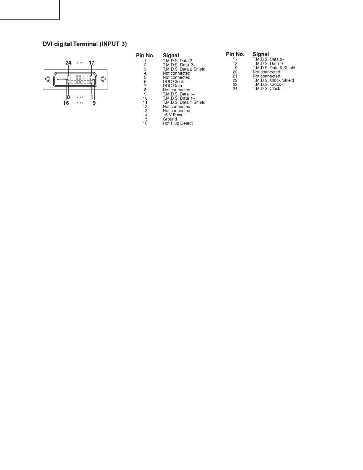
RGB digital input signal (INPUT 3) DVI connector (24-pin), RGB (digital), 250 –1,000 mV, 50 Ω (Compatible with HDCP)
Video input signal RCA connector: VIDEO, composite video, 1.0 Vp-p, sync negative, 75 Ω terminated
(INPUT 4)
S-video input signal 4-pin mini DIN connector
(INPUT 5) Y (luminance signal): 1.0 Vp-p, sync negative, 75 Ω terminated
Audio input signal ø3.5 mm stereo minijack: AUDIO, 0.5 Vrms, more than 22 kΩ
Audio output signal ø3.5 mm minijack
(AUDIO OUTPUT 1–5) 0.5 Vrms, less than 2.2 kΩ
RS-232C terminal 9-pin mini DIN connector
LAN terminal 8-pin RJ-45 modular connector
Pixel clock 12–230 MHz
Vertical frequency 43–200 Hz
Horizontal frequency 15–126 kHz
Audio output 3.0 W (stereo)
Speaker system 4.5 cm round ✕ 2
Rated voltage AC 100–240 V
Input current 6.3 A (AC 100 V)–2.6 A (AC 240 V)
Rated frequency 50/60 Hz
Power consumption 630 W (when "Eco Mode" is "OFF")/505 W (when "Eco Mode" is "ON") with AC 100 V
Power consumption (standby) 0.75 W (AC 100 V) – 1.25 W (AC 240 V) (When "Monitor Out" and "LAN/RS232C" are set to "Disable".)
Heat dissipation 2,370 BTU/hour (when "Eco Mode" is "OFF")/1,900 BTU/hour (when "Eco Mode" is "ON") with AC 100 V
Operating temperature 41°F to 104°F (+5°C to +40°C)
Storage temperature –4°F to 140°F (–20°C to +60°C)
Cabinet Plastic
I/R carrier frequency 38 kHz
Dimensions (approx.) 16
Weight (approx.) XG-PH50X: 32.7 lbs. (14.8 kg), XG-PH50X-NL: 30.0 lbs. (13.6 kg)
Replacement parts Lamp unit (AN-PH50LP1/AN-PH50LP2), Remote control (9NK5041808700), Power cord for U.S., Canada,
DTV480I/DTV480P/DTV540P/DTV576I/DTV576P/DTV720P/DTV1035I/DTV1080I
No. of dots: 786,432 dots (1,024 [H] ✕ 768 [V])
Lens 1.2 ✕ electric zoom/focus lens, F1.8–F2.0, f = 25.6–31.3 mm (standard equipment with XG-PH50X)
PB: 0.7 Vp-p, 75 Ω terminated
PR: 0.7 Vp-p, 75 Ω terminated
signal Y: 1.0 Vp-p, sync negative, 75 Ω terminated
PB: 0.7 Vp-p, 75 Ω terminated
PR: 0.7 Vp-p, 75 Ω terminated
HORIZONTAL SYNC. SIGNAL: TTL level (positive/negative)
VERTICAL SYNC. SIGNAL: Same as above
C (chrominance signal): Burst 0.286 Vp-p, 75 Ω terminated
600 W (when "Eco Mode" is "OFF")/485 W (when "Eco Mode" is "ON") with AC 240 V
2,260 BTU/hour (when "Eco Mode" is "OFF")/1,825 BTU/hour (when "Eco Mode" is "ON") with AC 240 V
5
/32" ✕ 7 3/32" ✕ 18 35/64" (410 (W) ✕ 180 (H) ✕ 471 (D) mm) (main body only)
16 5/32" ✕ 7 37/64" ✕ 18 35/64" (410 (W) ✕ 192.1 (H) ✕ 471 (D) mm) (including adjustment foot and projecting
parts)
etc. (9NK3090152800), Power cord for Europe, except U.K. (9NK3090152700), Power cord for U.K., Hong
Kong and Singapore (9NK3090152900), Power cord for Australia, New Zealand and Oceania (9NK3090152600),
RGB cable (9NK3080431000), Remote mouse receiver (9NK3790197000), Cap for the standard zoom lens
(9NK3797200400), Projector manual and technical reference CD-ROM (9NK3532094500), Operation manual
(9NK5010011800)
XG-PH50X
XG-PH50X-NL
As a part of policy of continuous improvement, SHARP reserves the right to make design and
specification changes for product improvement without prior notice. The performance specification figures indicated are nominal values of production units. There may be some deviations from
these values in individual units.
3
Page 4
XG-PH50X
2
2
XG-PH50X-NL
IMPORTANT SERVICE SAFETY NOTES (for USA)
Ë Service work should be performed only by qualified service technicians who are
thoroughly familiar with all safety checks and servicing guidelines as follows:
WARNING
1. For continued safety, no modification of any circuit
should be attempted.
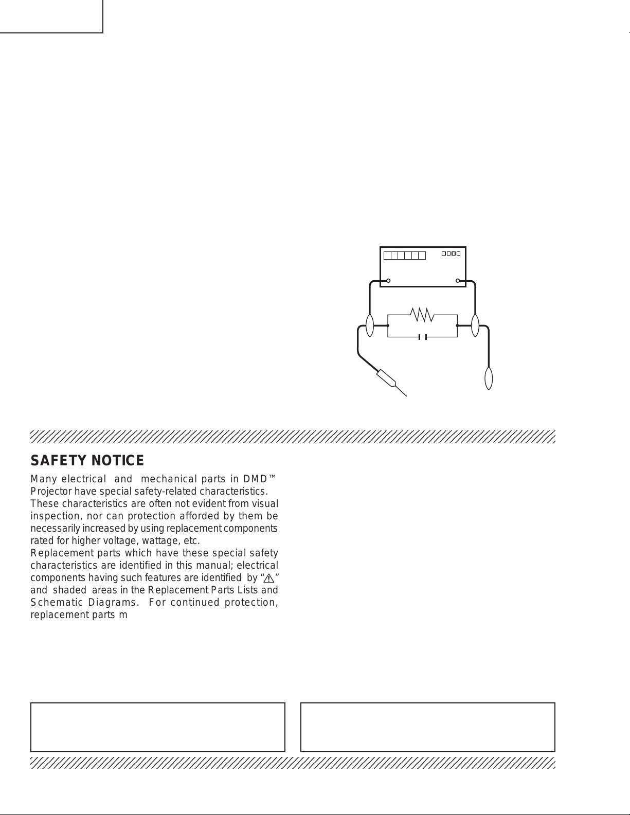
2. Disconnect AC power before servicing.
» Use an AC voltmeter with sensitivity of 5000 ohm per
volt., or higher, sensitivity to measure the AC voltage
drop across the resistor (See Diagram).
» All checks must be repeated with the AC plug
connection reversed. (If necessary, a non-polarized
adapter plug must be used only for the purpose of
BEFORE RETURNING THE PROJECTOR:
(Fire & Shock Hazard)
Before returning the projector to the user, perform
the following safety checks:
1. Inspect lead wires are not pinched between the chassis
completing these checks.)
Any reading of 0.3 volts RMS (this corresponds to 0.2
milliamp. AC.) or more is excessive and indicates a
potential shock hazard which must be corrected before
returning the unit to the owner.
and other metal parts of the projector.
2. Inspect all protective devices such as non-metallic
control knobs, insulating materials, cabinet backs,
DVM
AC SCALE
adjustment and compartment covers or shields,
isolation resistor-capacity networks, mechanical
insulators, etc.
1.5k ohm
10W
3. To be sure that no shock hazard exists, check for
current leakage in the following manner:
» Plug the AC cord directly into a 120-volt AC outlet, (Do
not use an isolation transformer for this test).
0.15 µF
TEST PROBE
» Using two clip leads, connect a 1.5k ohm, 10 watt
resistor paralleled by a 0.15µF capacitor in parallel
between all exposed metal cabinet parts and earth
ground.
234567890123456789012345678901212345678901234567890123456789012123456789012345678901234567890121
TO EXPOSED
METAL PARTS
CONNECT TO
KNOWN EARTH
GROUND
SAFETY NOTICE
Many electrical and mechanical parts in DMD™
Projector have special safety-related characteristics.
These characteristics are often not evident from visual
inspection, nor can protection afforded by them be
necessarily increased by using replacement components
rated for higher voltage, wattage, etc.
Replacement parts which have these special safety
characteristics are identified in this manual; electrical
components having such features are identified by “å”
and shaded areas in the Replacement Parts Lists and
Schematic Diagrams. For continued protection,
replacement parts must be identical to those used in
the original circuit. The use of a substitute replacement
parts which do not have the same safety characteristics
as the factory recommended replacement parts shown
in this service manual, may create shock, fire or other
hazards.
AVIS POUR LA SECURITE
De nombreuses pièces, électriques et mécaniques, dans
les projecteur à DMD™ présentent des caractéristiques
spéciales relatives à la sécurité, qui ne sont souvent pas
évidentes à vue.
Le degré de protection ne peut pas être nécessairement
augmentée en utilisant des pièces de remplacement
étalonnées pour haute tension, puissance, etc.
Les pièces de remplacement qui présentent ces
caractéristiques sont identifiées dans ce manuel;
les pièces électriques qui présentent ces particularités
sont identifiées par la marque “å” et hachurées dans la
liste des pièces de remplacement et les diagrammes
schématiques. Pour assurer la protection, ces pièces
doivent être identiques à celles utilisées dans le circuit
d’origine. L’utilisation de pièces qui n’ont pas les mêmes
caractéristiques que les pièces recommandées par l’usine,
indiquées dans ce manuel, peut provoquer des
électrocutions, incendies ou autres accidents.
WARNING: The bimetallic component has the primary
conductive side exposed. Be very careful in
handling this component when the power is on.
234567890123456789012345678901212345678901234567890123456789012123456789012345678901234567890121
AVERTISSEMENT:La composante bimétallique dispose du
conducteur primaire dénudé. Faire attention
lors de la manipulation de cette
composante sous tension.
4
Page 5
XG-PH50X
2
2
2
XG-PH50X-NL
PRECAUTIONS A PRENDRE LORS DE LA REPARATION
Ë
Ne peut effectuer la réparation qu' un technicien spécialisé qui s'est parfaitement
accoutumé à toute vérification de sécurité et aux conseils suivants.
AVERTISSEMENT
1. N'entreprendre aucune modification de tout circuit.
C'est dangereux.
2. Débrancher le récepteur avant toute réparation.
VERIFICA TIONS CONTRE L'INCEN-DIE ET
LE CMC ELECTRIQUE
Avant de rendre le récepteur à l'utilisateur, effectuer
les vérifications suivantes.
1. Inspecter tous les faisceaux de câbles pour s'assurer
que les fils ne soient pas pincés ou qu'un outil ne soit
pas placé entre le châssis et les autres pièces
métalliques du récepteur.
2. Inspecter tous les dispositifs de protection comme les
boutons de commande non-métalliques, les isolants, le
dos du coffret, les couvercles ou blindages de réglage
et de compartiment, les réseaux de résistance-capacité,
les isolateurs mécaniques, etc.
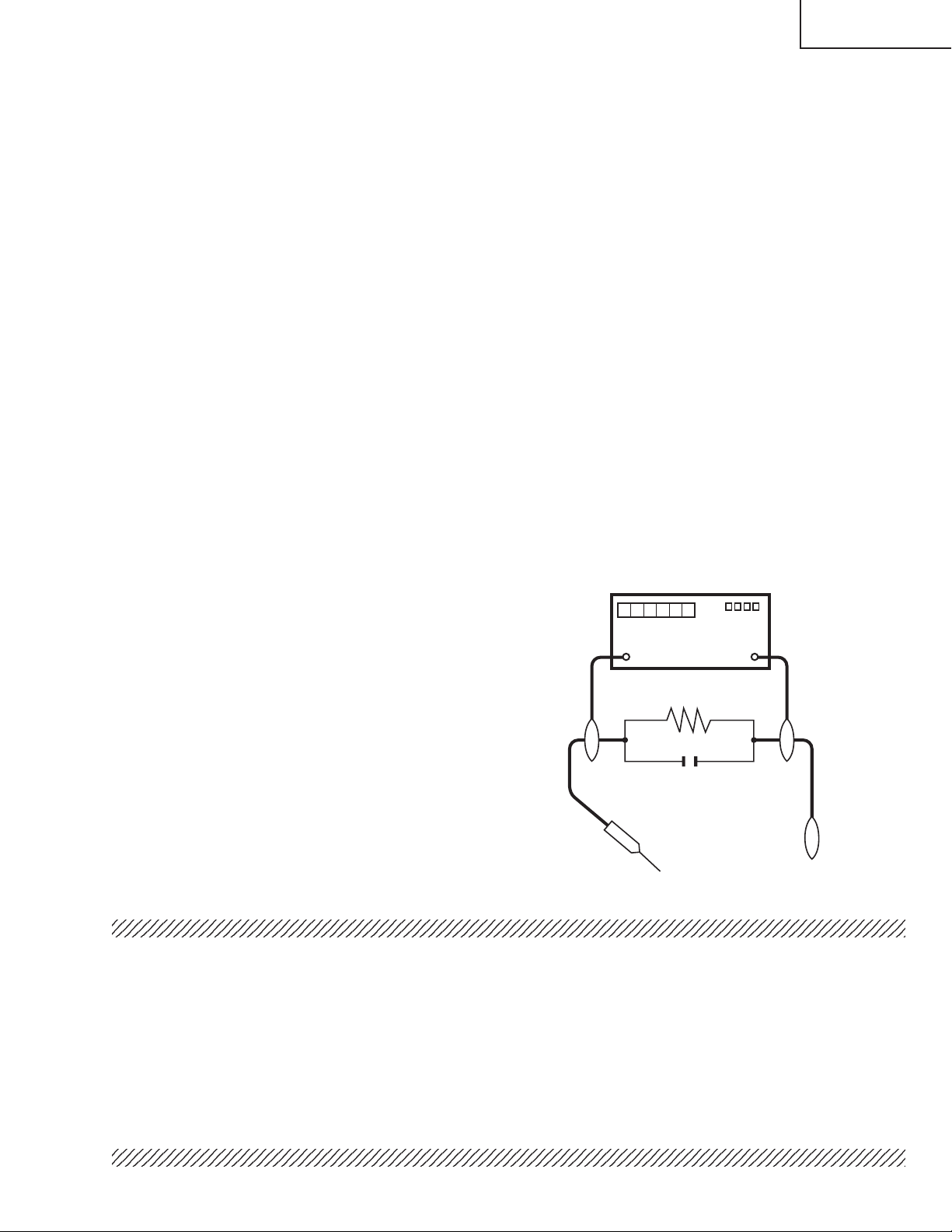
3. S'assurer qu'il n'y ait pas de danger d'électrocution en
vérifiant la fuite de courant, de la facon suivante:
• Brancher le cordon d'alimentation directem-ent à une
prise de courant de 120V. (Ne pas utiliser de
transformateur d'isolation pour cet essai).
• A l'aide de deux fils à pinces, brancher une résistance
de 1.5 kΩ 10 watts en parallèle avec un condensateur
de 0.15µF en série avec toutes les pièces métalliques
exposées du coffret et une terre connue comme une
conduite électrique ou une prise de terre branchée à la
terre.
• Utiliser un voltmètre CA d'une sensibilité d'au moins
5000Ω/V pour mesurer la chute de tension en travers
de la résistance.
• Toucher avec la sonde d'essai les pièces métalliques
exposées qui présentent une voie de retour au châssis
(antenne, coffret métallique, tête des vis, arbres de
commande et des boutons, écusson, etc.) et mesurer la
chute de tension CA en-travers de la résistance. Toutes
les vérifications doivent être refaites après avoir inversé
la fiche du cordon d'alimentation. (Si nécessaire, une
prise d'adpatation non polarisée peut être utilisée dans
le but de terminer ces vérifications.)
Tous les courants mesurés ne doivent pas dépasser 0.5
mA.
Dans le cas contraire, il y a une possibilité de choc
électrique qui doit être supprimée avant de rendre le
récepteur au client.
DVM
ECHELLE CA
1.5k ohm
10W
0.15 µF
SONDE D'ESSAI
AUX PIECES
METALLIQUES
EXPOSEES
234567890123456789012345678901212345678901234567890123456789012123456789012345678901234567890121
BRANCHER A UNE
TERRE CONNUE
AVIS POUR LA SECURITE
De nombreuses pièces, électriques et mécaniques, dans les téléviseur ACL présentent des caractéristiques spéciales
relatives à la sécurité, qui ne sont souvent pas évidentes à vue. Le degré de protection ne peut pas être nécessairement
augmentée en utilisant des pièces de remplacement étalonnées pour haute tension, puissance, etc.
Les pièces de remplacement qui présentent ces caractéristiques sont identifiées dans ce manuel; les pièces électriques
qui présentent ces particularités sont identifiées par la marque " å " et hachurées dans la liste des pièces de
remplacement et les diagrammes schématiques.
Pour assurer la protection, ces pièces doivent être identiques à celles utilisées dans le circuit d'origine. L'utilisation
de pièces qui n'ont pas les mêmes caractéristiques que les pièces recommandées par l'usine, indiquées dans ce
manuel, peut provoquer des électrocutions, incendies, radiations X ou autres accidents.
234567890123456789012345678901212345678901234567890123456789012123456789012345678901234567890121
234567890123456789012345678901212345678901234567890123456789012123456789012345678901234567890121
5
Page 6
XG-PH50X
XG-PH50X-NL
NOTE TO SERVICE
PERSONNEL
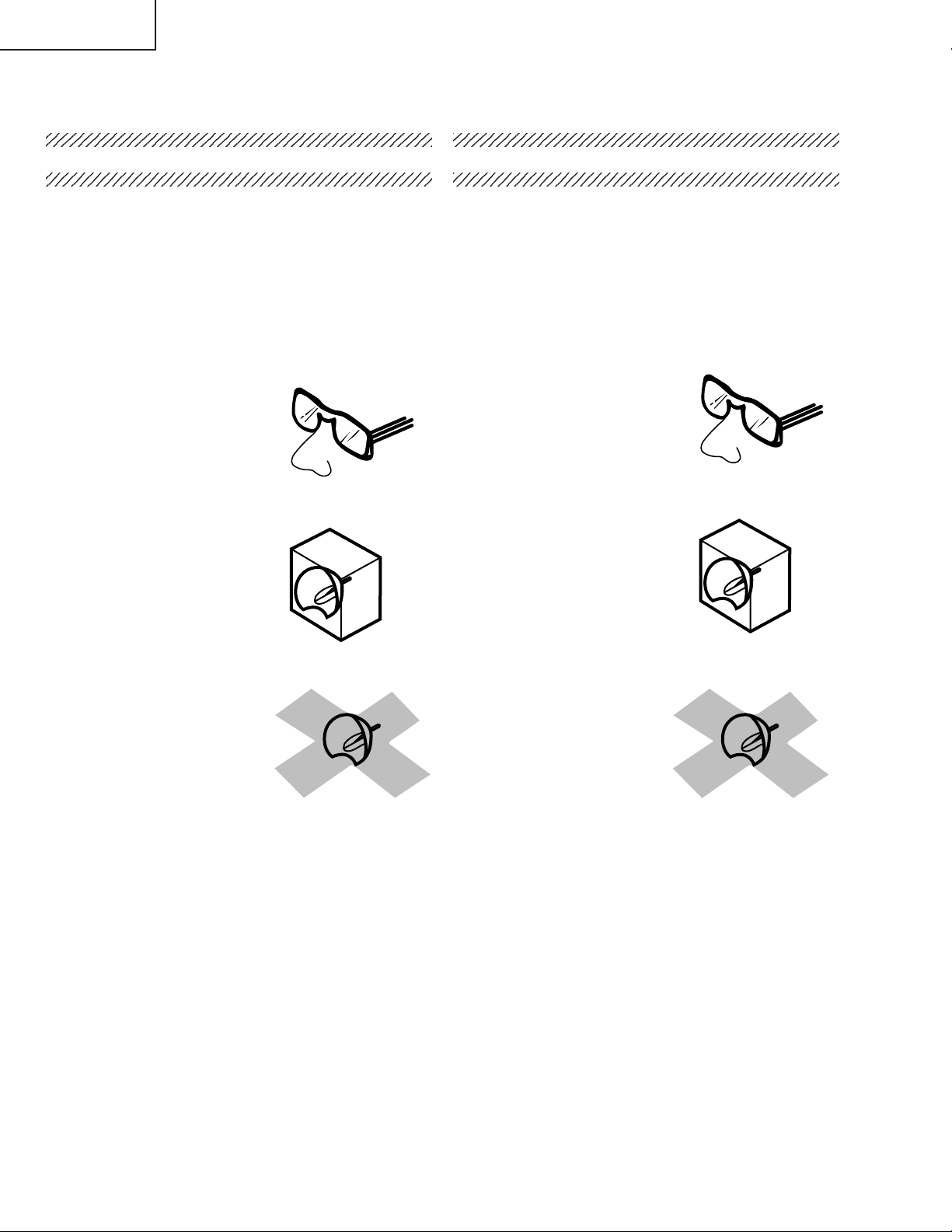
UV-RADIATION PRECAUTION
The light source, UHP lamp, in the LCD projector
emits small amounts of UV-Radiation.
AVOID DIRECT EYE AND SKIN EXPOSURE.
To ensure safety please adhere to the following:
1. Be sure to wear sun-glasses when servicing the
projector with the lamp
turned “on” and the top
enclosure removed.
2. Do not operate the lamp outside of the lamp housing.
NOTE POUR LE PERSONNEL
D’ENTRETIEN
PRECAUTION POUR LES RADIA TIONS UV
La source de lumière, la lampe UHP, dans le projecteur
LCD émet de petites quantités de radiation UV.
EVITEZ TOUTE EXPOSITION DIRECTE DES
YEUX ET DE LA PEAU.
Pour votre sécurité, nous vous prions de respecter
les points suivants:
1. Toujours porter des lunettes de soleil lors d’un entretien
du projecteur
avec la lampe allumée
et le haut du coffret retiré.
2. Ne pas faire fonctionner la lampe à l’extérieur du boîtier
de lampe.
3. Do not operate for more than 2 hours with the enclosure
removed.
UV-Radiation and Medium Pressure
Lamp Precautions
1. Be sure to disconnect the AC plug when replacing the
lamp.
2. Allow one hour for the unit to cool down before
servicing.
3. Replace only with same type lamp. T ype AN-PH50LP1/
AN-PH50LP2 rated 250W.
4. The lamp emits small amounts of UV-Radiation, avoid
direct-eye contact.
5. The medium pressure lamp involves a risk of explosion.
Be sure to follow installation instructions described
below and handle the lamp with care.
3. Ne pas faire fonctionner plus de 2 heures avec le coffret
retiré.
Précautions pour les radiations UV
et la lampe moyenne pression
1. Toujours débrancher la fiche AC lors du remplacement
de la lampe.
2. Laisser l’unité refroidir pendant une heure avant de
procéder à l’entretien.
3. Ne remplacer qu’avec une lampe du même type. Type
AN-PH50LP1/AN-PH50LP2, caractéristique 250W.
4. La lampe émet de petites quantités de radiation UVéviter tout contact direct avec les yeux.
5. La lampe moyenne pression implique un risque
d’explosion. Toujours suivre les instructions
d’installation décrites ci-dessous et manipuler la lampe
avec soin.
6
Page 7
2345678901234567890123456789012123456789012345
6
6
6
6
XG-PH50X
XG-PH50X-NL
2345678901234567890123456789012123456789012345
UV-RADIATION PRECAUTION (Continued)
2345678901234567890123456789012123456789012345
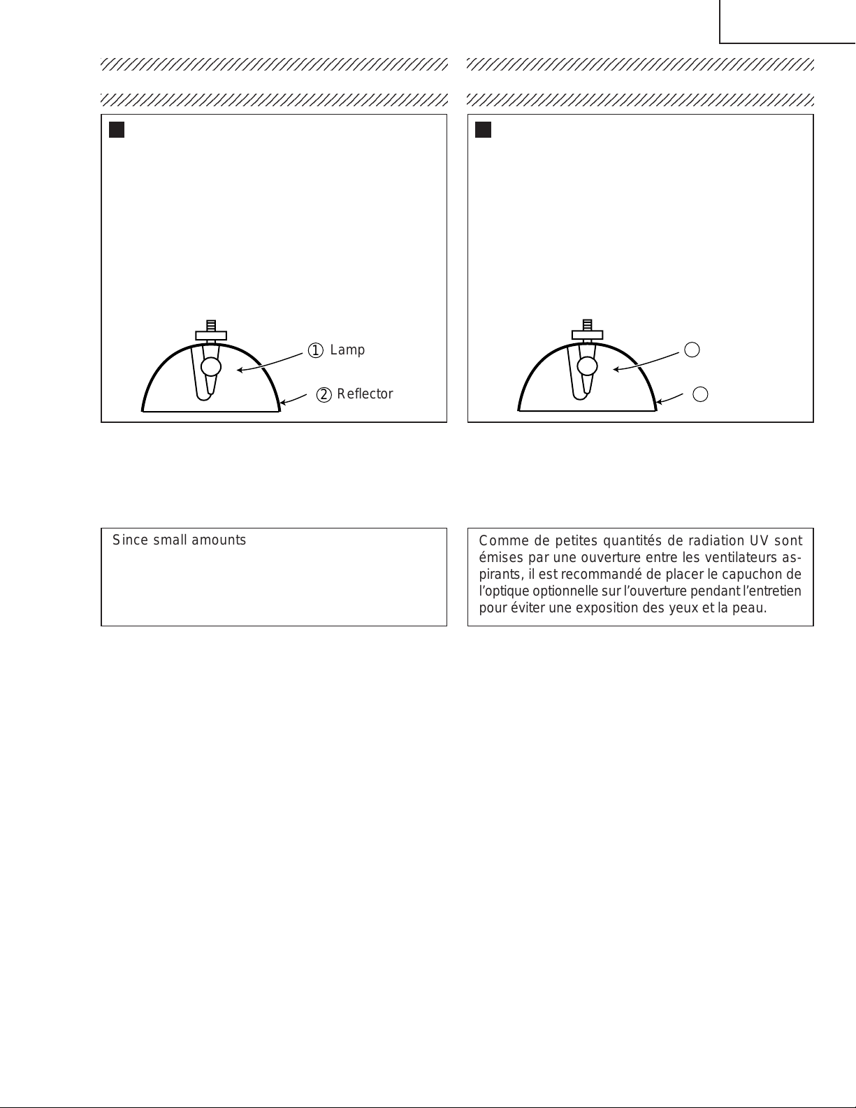
Lamp Replacement
Note:
Since the lamp reaches a very high temperature during
units operation replacement of the lamp should be
done at least one hour after the power has been turned
off. (to allow the lamp to cool off.)
Installing the new lamp, make sure not to touch the
lamp (bulb) replace the lamp by holding its reflector
2.
[Use original replacement only.]
Lamp
1
Reflector
2
DANGER ! –– Never turn the power on without the
lamp to avoid electric-shock or damage of the devices
since the stabilizer generates high voltages at its start.
PRECAUTION POUR LES RADIATIONS UV (Suite)
2345678901234567890123456789012123456789012345
Remplacement de la lampe
Remarque:
Comme la lampe devient très chaude pendant le
fonctionnement de l’unité, son remplacement ne doit
être effectué au moins une heure après avoir coupé
l’alimentation (pour permettre à la lampe de refroidir).
En installant la nouvelle lampe, s’assurer de ne pas
toucher la lampe (ampoule). Remplacer la lampe en
tenant son réflecteur 2.
[N’utiliser qu’un remplacement d’origine.]
1
Lampe
2
Reflecteur
DANGER ! –– Ne jamais mettre sous tension sans la
lampe pour éviter un choc électrique ou des
dommages des appareils car le stabilisateur génère
de hautes tensions à sa mise en route.
Since small amounts of UV-radiation are emitted
from an opening between the exhaust fans, it is recommended to place the cap of the optional lens on
the opening during servicing to avoid eye and skin
exposure.
Comme de petites quantités de radiation UV sont
émises par une ouverture entre les ventilateurs aspirants, il est recommandé de placer le capuchon de
l’optique optionnelle sur l’ouverture pendant l’entretien
pour éviter une exposition des yeux et la peau.
7
Page 8
XG-PH50X
XG-PH50X-NL
WARNING: High brightness light source, do not stare into the beam of light, or view directly . Be especially
careful that children do not stare directly in to the beam of light.
WARNING: TO REDUCE THE RISK OF FIRE OR ELECTRIC SHOCK, DO NOT EXPOSE THIS UNIT TO
MOISTURE OR WET LOCATIONS.
CAUTION
RISK OF ELECTRIC SHOCK.
DO NOT REMOVE SCREWS
EXCEPT SPECIFIED USER
SERVICE SCREW.
CAUTION: TO REDUCE THE RISK OF ELECTRIC SHOCK,
DO NOT REMOVE CABINET .
NO USER-SERVICEABLE P ARTS EXCEPT LAMP UNIT.
REFER SERVICING TO QUALIFIED SERVICE
PERSONNEL.
The lighting flash with arrowhead within a
triangle is intended to tell the user that
parts inside the product are risk of electric
shock to persons.
The exclamation point within a triangle is
intended to tell the user that important
operating and servicing instructions are in
the manual with the projector.
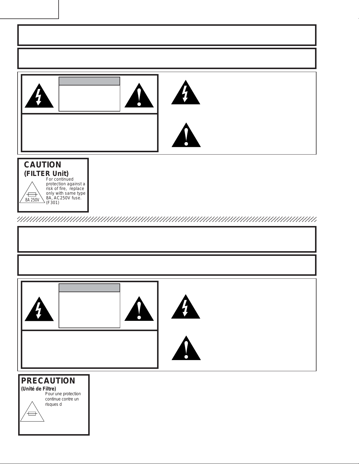
CAUTION
(FILTER Unit)
8A 250V
AVERTISSEMENT: Source lumineuse de grande intensité. Ne pas fixer le faisceau lumineux ou le regarder
For continued
protection against a
risk of fire, replace
only with same type
8A, AC250V fuse.
(F301)
directement. Veiller particulièrement à éviter que les enfants ne fixent directement le
faisceau lumineux.
AVERTISSEMENT: AFIN D’EVITER TOUT RISQUE D’INCENDIE OU D’ELECTROCUTION, NE PAS PLACER
CET APPAREIL DANS UN ENDROIT HUMIDE OU MOUILLE.
ATTENTION
RISQUE
D’ÉLECTROCUTION. NE
PASR ETIRER LES VIS Á
L’EXCEPTION DE LA VIS DE
REPARATION UTILISATEUR
SPECIFIEES
L’éclair terminé d’une flèche à l’intérieur
d’un triangle indique à l’utilisateur que les
pi‘eces se trouvant dans l’appareil sont
susceptibles de provoquer une décharge
électrique.
Le point d’exclamation à l’intérieur d’un
ATTENTION: POUR EVITER TOUT RISQUE
D’ELECTROCUTION, NE PAS RETIRER LE CAPOT.
AUCUNE DES PIECES INTERIEURES N’EST REP ARABLE
PAR L’UTILISA TEUR, A L’EXCEPTION DE L’UNITE DE
LAMPE. POUR TOUTE REP ARATION, S’ADRESSER A UN
TECHNICIEN D’ENTRETIEN QUALIFIE.
triangle indique à l’utilisateur que les
instructions de fonctionnement et
d’entretien sont détaillées dans les
documents fournis avec le projecteur.
PRECAUTION
(Unité de Filtre)
8A 250V
Pour une protection
continue contre un
risques d’incendie, ne
remplacer qu’avec un
fusible 8A,AC250V
du même type.
(F301)
8
Page 9
XG-PH50X
XG-PH50X-NL
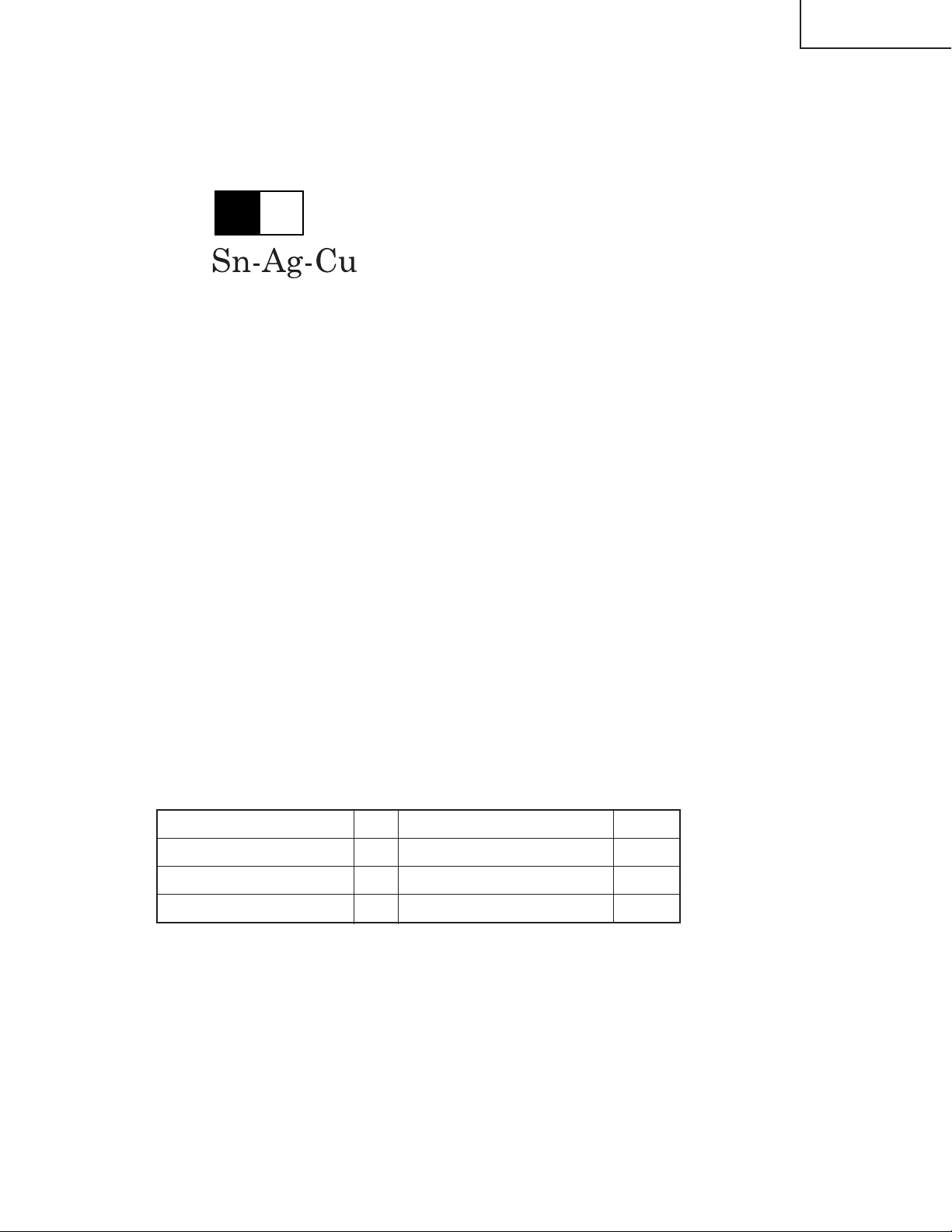
Precautions for using lead-free solder
1 Employing lead-free solder
"PWBs" of this model employs lead-free solder. The LF symbol indicates lead-free solder, and is attached on the
PWBs and service manuals. The alphabetical character following LF shows the type of lead-free solder.
Example:
L Fa
Indicates lead-free solder of tin, silver and copper.
2 Using lead-free wire solder
When fixing the PWB soldered with the lead-free solder, apply lead-free wire solder. Repairing with conventional
lead wire solder may cause damage or accident due to cracks.
As the melting point of lead-free solder (Sn-Ag-Cu) is higher than the lead wire solder by 40°C, we recommend you
to use a dedicated soldering bit, if you are not familiar with how to obtain lead-free wire solder or soldering bit,
contact our service station or service branch in your area.
3 Soldering
As the melting point of lead-free solder (Sn-Ag-Cu) is about 220°C which is higher than the conventional lead solder
by 40°C, and as it has poor solder wettability, you may be apt to keep the soldering bit in contact with the PWB for
extended period of time. However, since the land may be peeled of f or the maximum heat-resistance temperature of
parts may be exceeded, remove the bit from the PWB as soon as you confirm the steady soldering condition.
Lead-free solder contains more tin, and the end of the soldering bit may be easily corroded. Make sure to turn on
and off the power of the bit as required.
If a different type of solder stays on the tip of the soldering bit, it is alloyed with lead-free solder. Clean the bit after
every use of it.
When the tip of the soldering bit is blackened during use, file it with steel wool or fine sandpaper.
Be careful when replacing parts with polarity indication on the PWB silk.
Lead-free wire solder for servicing
Part No. ★ Description Code
ZHNDAi123250E J φ0.3mm 250g(1roll) BL
ZHNDAi126500E J φ0.6mm 500g(1roll) BK
ZHNDAi12801KE J φ1.0mm 1kg(1roll) BM
9
Page 10
XG-PH50X
XG-PH50X-NL
Operation Manual
10
Page 11
XG-PH50X
XG-PH50X-NL
11
Page 12
XG-PH50X
XG-PH50X-NL
12
Page 13
XG-PH50X
XG-PH50X-NL
13
Page 14
XG-PH50X
XG-PH50X-NL
14
Page 15
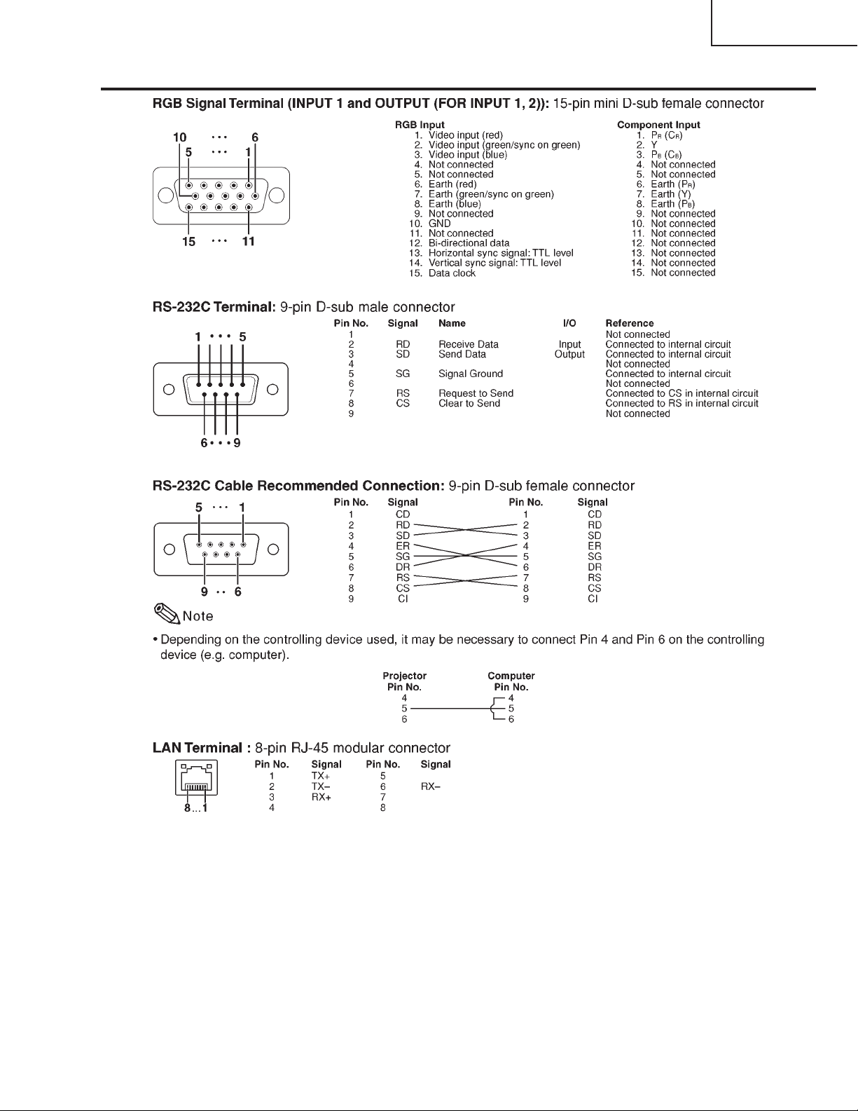
Connection Pin Assignments
XG-PH50X
XG-PH50X-NL
15
Page 16
XG-PH50X
XG-PH50X-NL
16
Page 17
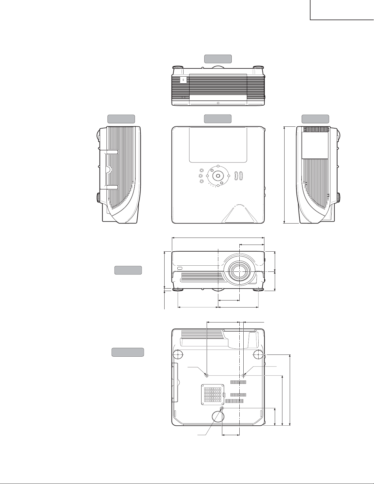
DIMENSIONS
XG-PH50X
XG-PH50X-NL
Units: inches (mm)
Side View Side View
Rear View
Top View
(471)
64
/
35
18
Front View
Bottom View
(180)
32
/
3
7
(12.1)
64
/
31
165/32 (410)
3
/4 (94.9)
3
547/64 (145.5)
M4
M4
7
3
3
(77.27)
11
/32 (110.1)
4
(97.8)3
64
/
55
3
(94.3)
32
/
23
1
/16 (179)71/16 (179)
45
/64 (17.5)
M4
(346)
8
/
5
13
(243.9)
64
/
39
9
(85)
64
/
23
/
64
3
17
Page 18
XG-PH50X
XG-PH50X-NL
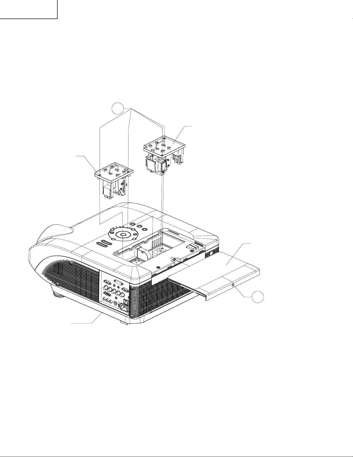
REMOVING OF MAJOR PARTS
1.Removing the Lamp Unit
1-1. Remove the screw from the lamp cover and detach the lamp cover.
1-2. Remove the four screws from the lamp units and take out the lamp units.
1-2
Lamp Unit 2
Lamp Unit 1
Bottom Case
Lamp Cover
1-1
18
Page 19
XG-PH50X
XG-PH50X-NL
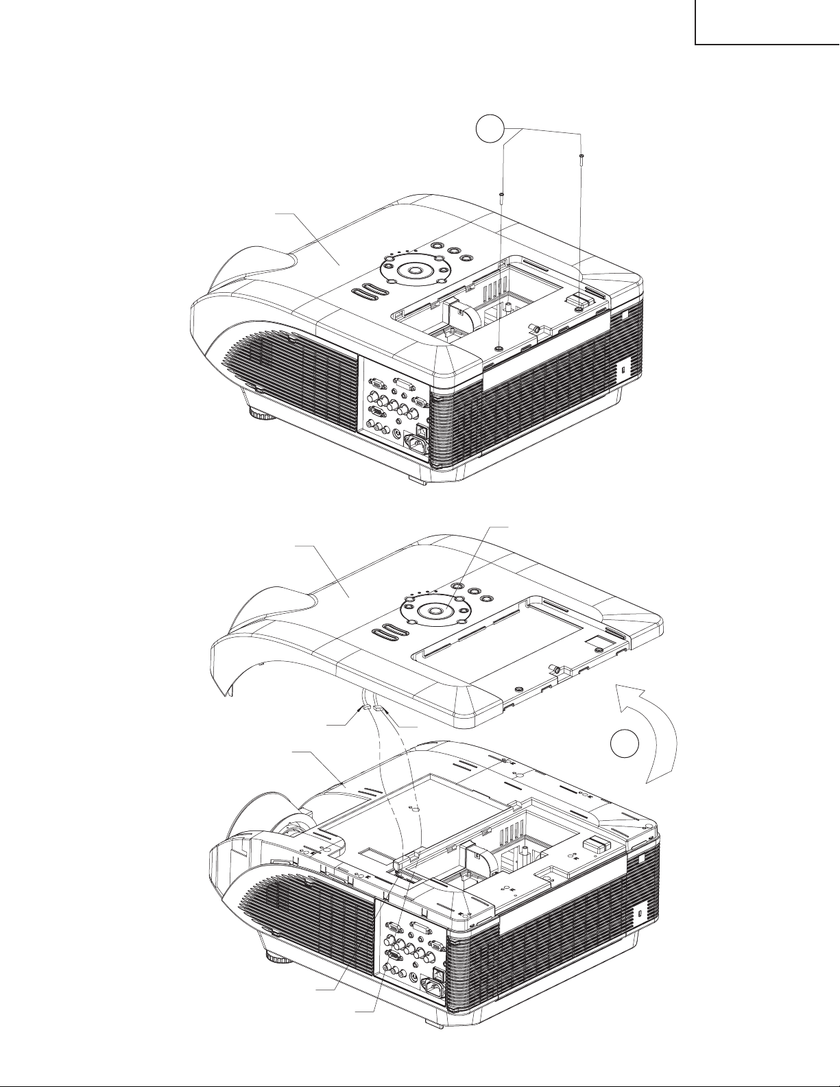
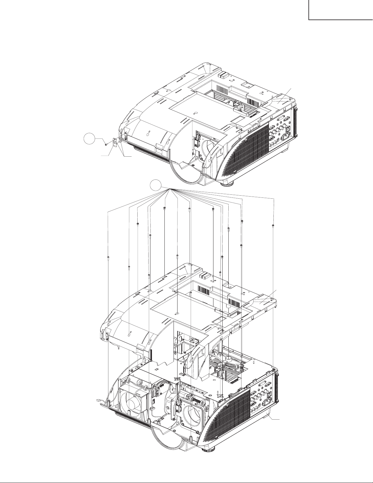
2.Removing the Top Cover
2-1. Remove the two screws from the top cover.
2-2. Slowly lift the back of the top cover and disconnect the operation key connectors (KY1 and KY2). Pull up and
off the top cover.
Top Cover
2-1
Top Cover
Top Cabinet
KY1
Operation Key
KY2
2-2
KY1
KY2
19
Page 20
XG-PH50X
XG-PH50X-NL
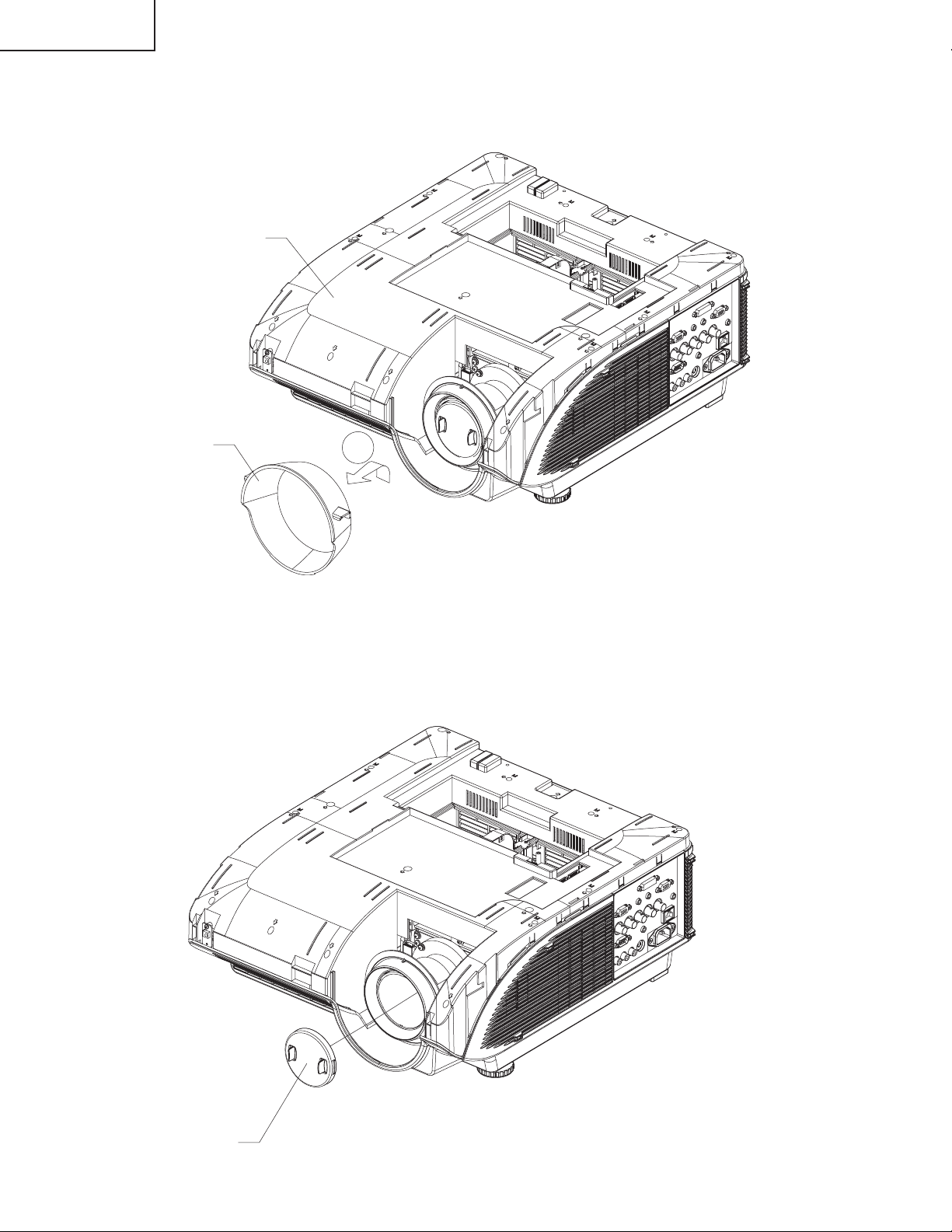
For XG-PH50X-NL, the lens removal operations (sections 3 - 6) are unnecessary.
3.Removing the Lens Hood
3-1. Slowly lift the lens hood up until it can be moved forward and then move it forward and detach the lens hood.
Top Cabinet
Lens Hood
4.Removing the Lens Cap
4-1. Remove the lens cap.
3-1
Lens Cap
20
Page 21
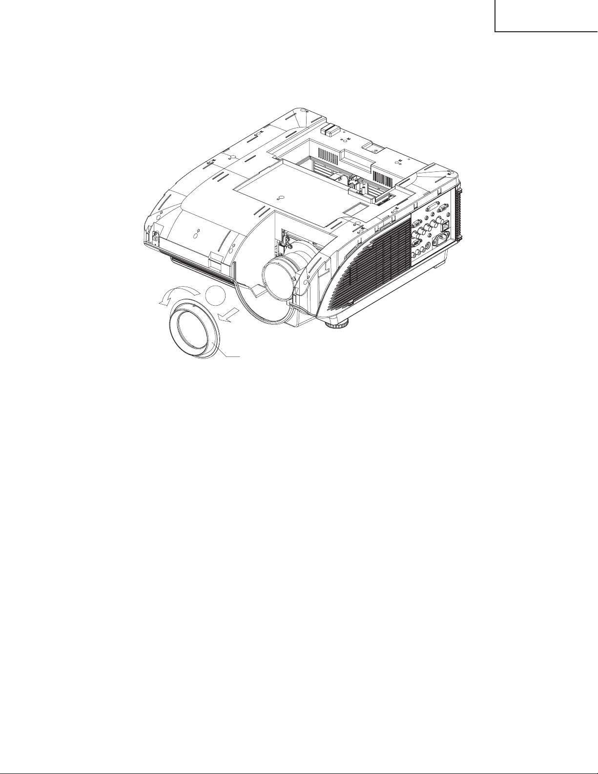
5.Removing the Lens Trim
5-1. Rotate the lens trim counterclockwise and then detach the lens trim.
XG-PH50X
XG-PH50X-NL
5-1
Lens Trim
21
Page 22
XG-PH50X
XG-PH50X-NL
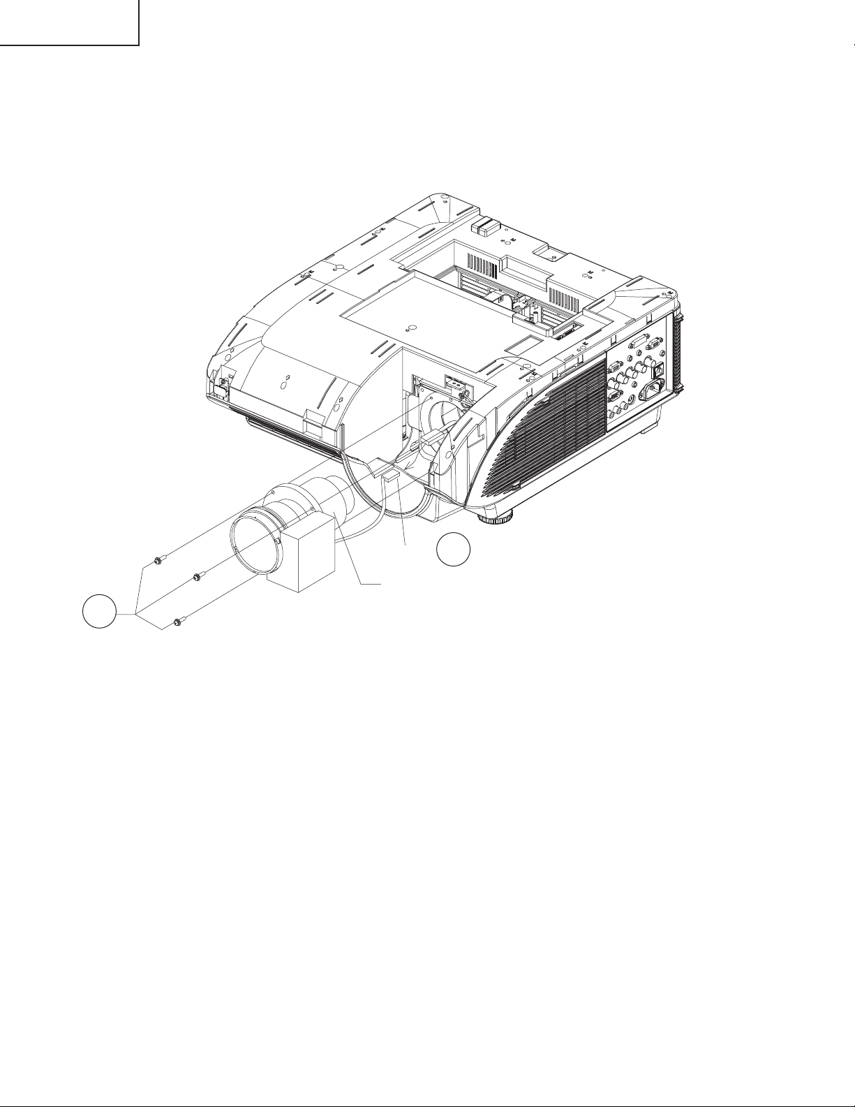
6.Removing the Standard Lens
6-1. Disconnect the standard lens connector (SL).
6-2. Remove the three screws from the standard lens and take out the standard lens.
6-2
SL
6-1
Standard Lens
22
Page 23
XG-PH50X
XG-PH50X-NL
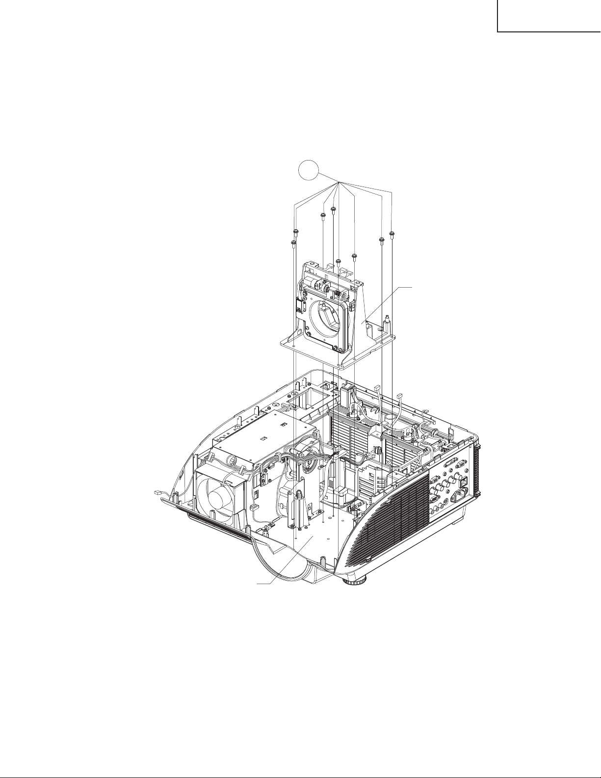
7.Removing the Top Cabinet
7-1. Remove the screw from IR(Front) unit, take out the IR(Front) unit and then disconnect the IR(Front) unit
connector (RC).
7-2. Remove the sixteen screws from the top cabinet and then pull up and off the top cabinet.
Top Cabinet
7-1
IR(Front) Unit
RC
7-2
Top Cabinet
23
Bottom Case
Page 24
XG-PH50X
XG-PH50X-NL
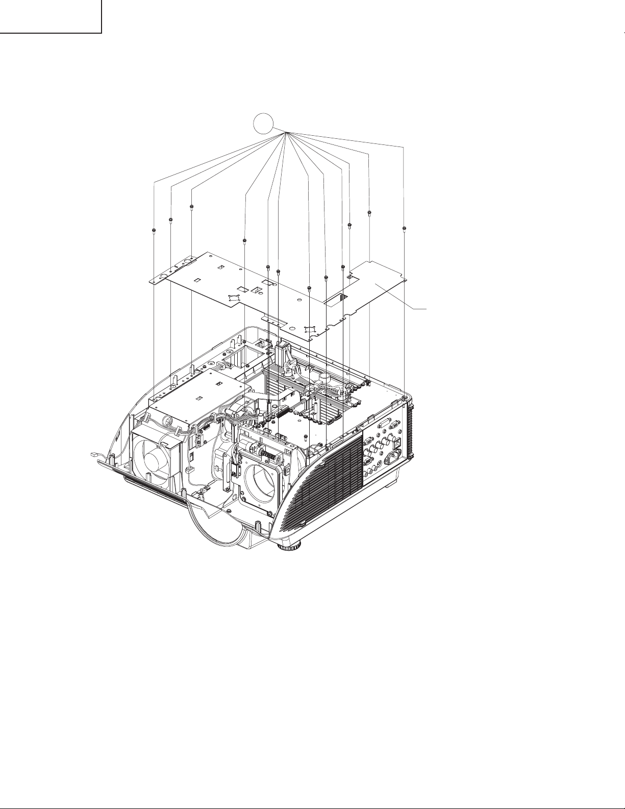
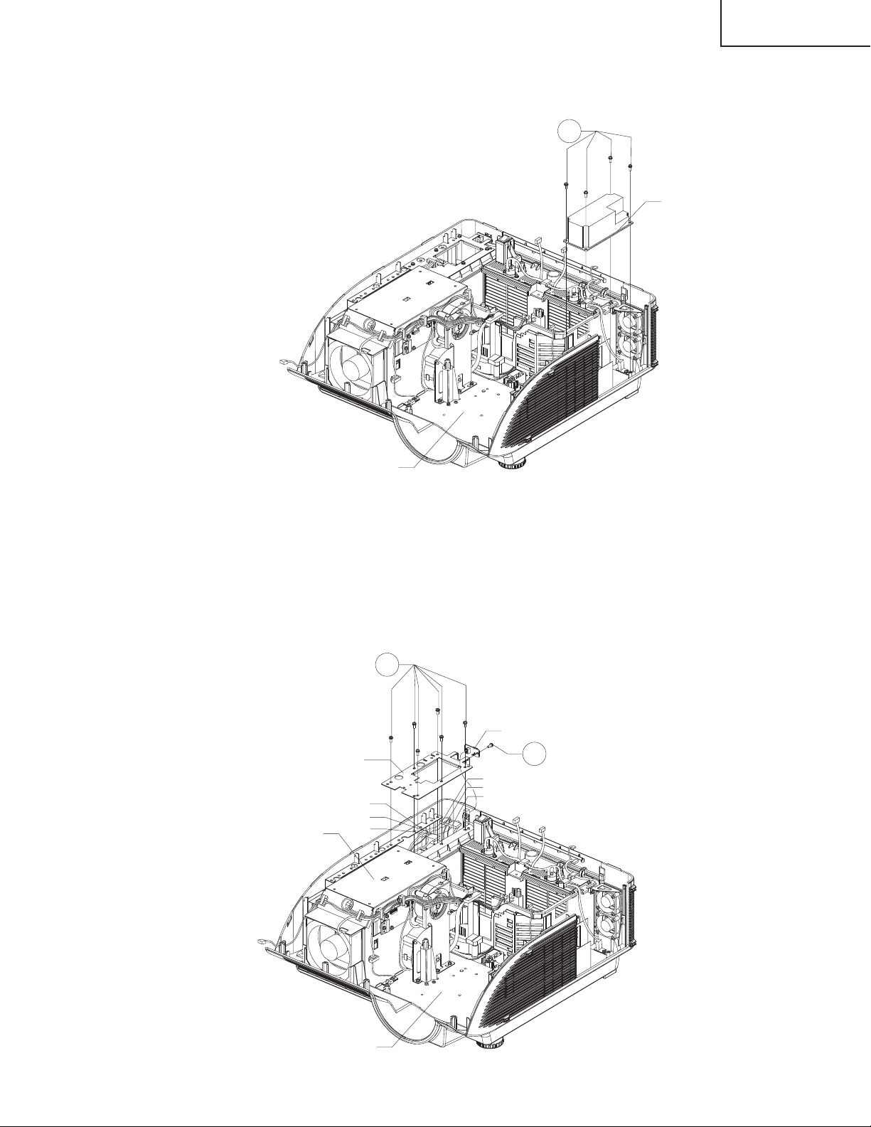
8.Removing the Handle Bracket3
8-1. Remove the Twelve screws from the handle bracket3 and detach the handle bracket3.
8-1
Handle Bracket3
24
Page 25
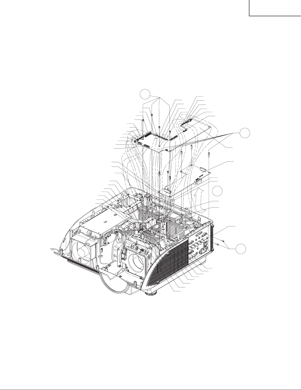
9.Removing the PWBA Units
9-1. Disconnect all the connector from the Main Unit.
9-2. Remove the four screws from the Main Unit. Detach the Main Unit from the PC I/F Unit.
9-3. Remove the two spacers from the PC I/F Unit.
9-4. Remove the five spacers and the screw.
9-5. Disconnect the PC I/F Unit from the Terminal Unit and then detach the PC I/F Unit.
XG-PH50X
XG-PH50X-NL
LSUD
LSRL
LSR
FC4
IR(Rear) Unit
CW
BTL
PR
BTR
TS
RC
FC1
FC1
FR
RC
AD
BTR
TS
BTL
PR
LSF
CW
9-2
FC3
FC2
FC5
TS
LSR
FC6
FC4
FC7
RC
LSL
9-5
LSL
FC6
RC
FC7
9-4
Main Unit
PC I/F Unit
Terminal Unit
25
FR
LSRL
LSUD
LSF
FC3
FC2
FC5
9-3
TS
Page 26
XG-PH50X
XG-PH50X-NL
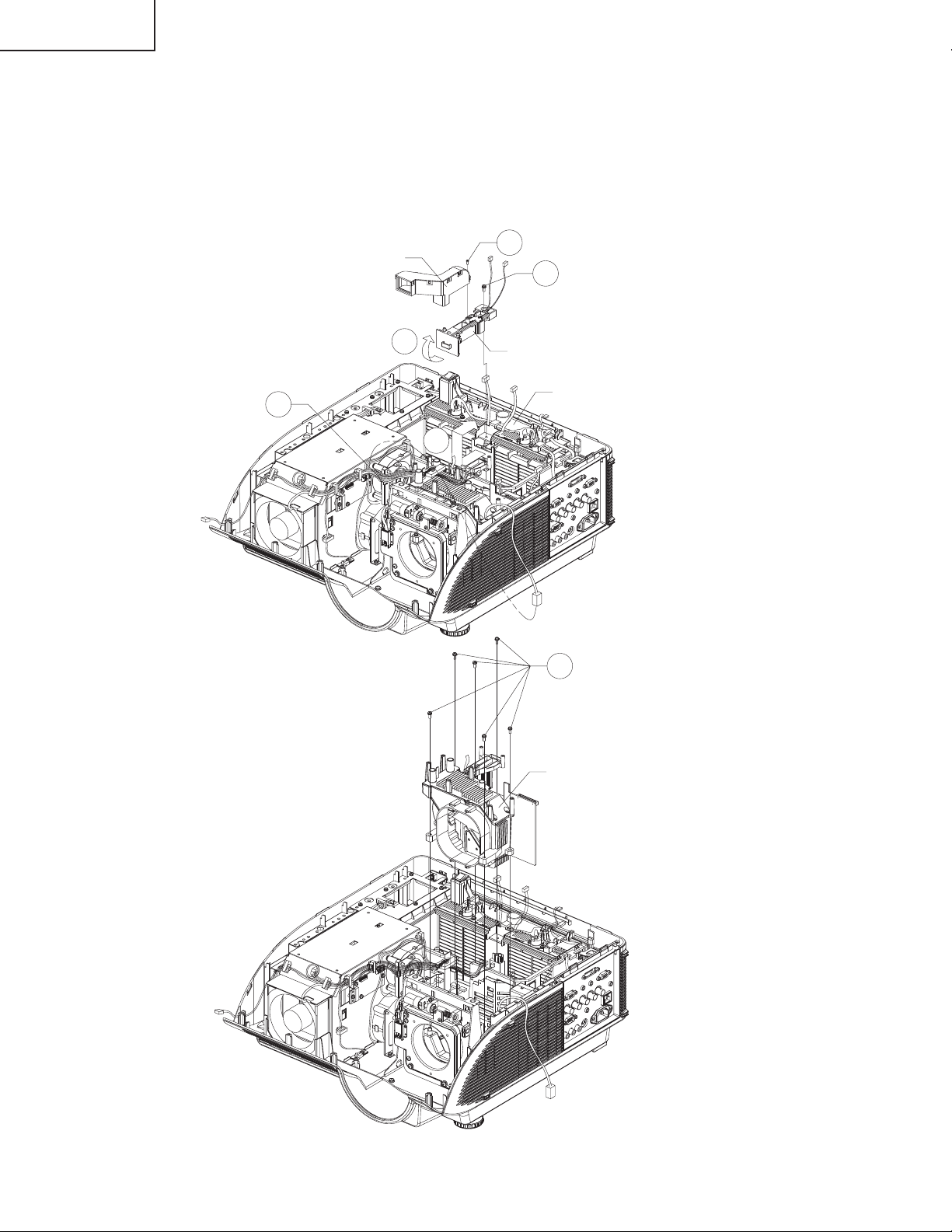
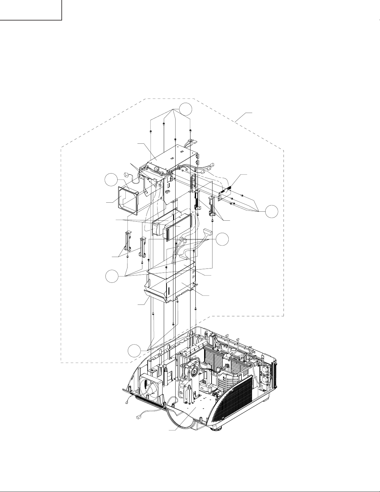
10. Removing the Optical Engine
10-1. Remove the screw from the rod duct and then detach the rod duct.
10-2. Remove the screw from the lamp channel top.
10-3. Unhook the front of the lamp channel top and take it out.
10-4. Slide the bimetal cover and detach it out.
10-5. Release the cable tie and then disconnect the left speaker connector. Remove the six screws from the
optical engine and then lift the optical engine out of position.
10-5
Rod Duct
10-3
10-1
10-2
Lamp Channel Top
Bimetal Cover
10-4
10-5
26
Optical Engine
Page 27
11. Removing the Lens Shift
11-1. Remove the eight screws from the lens shift and then lift the lens shift out of position.
11-1
Lens Shift
XG-PH50X
XG-PH50X-NL
Chassis
27
Page 28

XG-PH50X
XG-PH50X-NL
12. Removing the Terminal Unit
12-1. Remove the five screws from the terminal bracket, lift the terminal bracket and then disconnect the AC
socket.
12-2. Remove the six spacers from the terminal unit.
12-3. Remove the six screws from the terminal unit and take out the terminal unit.
12-1
12-3
Terminal Unit
Chassis
12-2
Terminal Bracket
28
Page 29
XG-PH50X
XG-PH50X-NL
13. Removing the Filter Unit
13-1. Disconnect all the connectors from the filter unit. Remove the four screws from the filter unit and then take it
out.
13-1
Filter Unit
Chassis
14. Removing the IR(Rear) Unit
14-1 Disconnect all the connectors from the power unit. Remove the six screws from the Plate and then take out
the Plate.
14-2. Remove the screw from the IR(Rear) unit and detach the IR(Rear) unit.
14-1
IR(Rear) Unit
PR3
PR2
PR1
14-2
Power Unit
Plate
PR3
PR2
PR1
Chassis
29
Page 30
XG-PH50X
XG-PH50X-NL
15. Removing the Power Unit and Audio Unit
15-1. Remove the four screws from the power unit.
15-2. Detach the power air guide from the power channel upper.
15-3. Remove the four screws from the power channel down and then disconnect the two power connector PR.
15-4. Remove the four screws from the power unit and then take out the power unit.
15-5. Remove the four screws from the holders and then disconnect the signal connectors SG.
15-6 Remove the four screws from the audio unit and then take out the audio unit.
Power Channel upper
Power Air Guide
Ballast Unit
Holder
15-2
15-5
SG
15-1
Power Unit
Audio Unit
15-6
Holder
15-4
Power Unit
Power Channel Down
15-3
Power Unit Insulator
Chassis
30
Page 31

RESETTING THE TOTAL LAMP TIMER
● Resetting the total lamp timer
When replacing the lamp, reset the total lamp timer in the procedure below.
XG-PH50X
XG-PH50X-NL
Lamp
■ It is recommended that the lamp units (optional: AN-PH50LP1 and AN-PH50LP2) be replaced when the remaining
lamp life becomes 5% or less, or when you notice a significant deterioration in the picture and color quality. The
lamp life (percentage) can be checked with the on-screen display.
■ Purchase a replacement lamp unit of type AN-PH50LP1 and AN-PH50LP2 from your place of purchase, nearest
Sharp Authorized Projector Dealer or Service Center.
31
Page 32

XG-PH50X
XG-PH50X-NL
32
Page 33

XG-PH50X
XG-PH50X-NL
ELECTRICAL ADJUSTMENT
- Turn on the power (lamp on state) and wait for 15 minutes for aging.
- Enter the adjustment process mode with S3602 (tact switch) on the main board.
In case that top cabinet covered S3602, you can enter by pushing key continuously in sequence.
key pad On -> Up -> Down -> Up -> Down -> Enter -> Enter -> Menu
Remote controler On -> Vol up -> Vol down -> Vol up -> Vol down -> Enter -> Enter -> Menu
* You can exit from factory mode by same method.(Or select "EXIT" in the process mode to exit.)
- Select the group to adjust with the DOWN key or the UP key, and enter the adjustment item with the ENTER
key on the remote control or key pad.
- Select the adjustment item with the DOWN key or the UP key.
- Use the LEFT key or the RIGHT key for adjustment.
- To return from the adjustment item to the adjustment group, use the UNDO key or the MENU key.
- Change internal test pattern and input signal with the MUTE key
No. Adjusting point Adjusting conditions Adjusting procedure
1 Initialization of
EEPROM
2Write MAC
address
3 Adjustment of
CW index
1. Turn on the power (the
lamp lights up) and warm
up the system for 15 minutes.
2. Select the following group
and subject.
Group: SSS
Subject: S2
1. Signal input: 64 STEP color
bar signal.
2. Select the following group
and subjects.
Group : DLP
Subject : CW-INDEX
1. Press S3602 to enter the process mode.
2. Execute the S2 command on the SSS menu.
*With the S2 command, all the circuit boards than
the PC board will be initialized.
(Note)
Since the PC I/F unit is initialized with S1, do not
carry out S1.
The PC I/F unit is already adjusted.
When the PC I/F unit must be adjusted, in such
case as S1 is carried out by mistake, adjust it
according to the "PC I/F adjustment method" at
the end of this document.
3. Wait approximately 30 seconds and when "INPUT1" appears, turn off the power.
4. After all the fans stop, turn the power back on.
1. Read a sticker which is written mac address on main
board.
2. Write MAC address by 232c serial cable.(For the procedure, refer to the attachment.)
1. Feed the signal to INPUT 1.
2. Select subject and make adjustment so that the uniformity should be smooth.
R
4 Adjustment of
DLP voltage
1. SRead voltage rank of DLP
description.
2. Select the following group
and subjects.
Group : DLP
Subject : DMD-BIN
G
B
1. Adjust DMD-BIN corresponding to the rank which
has been read. (on the main board)
Rank / setting value
B / 0
C / 1
D / 2
E / 3
*Carry out adjustment when DLP chip or PC board has
been replaced
33
Page 34

XG-PH50X
XG-PH50X-NL
No. Adjusting point Adjusting conditions Adjusting procedure
5-1 Adjustment of
Video brightness
5-2 Adjustment of
Video contrast
6 Adjustment of
component Cr/
Cb offset (1)
7 Adjustment
ofcomponent
brightness
1. Select the following group
and subject.
Group : VIDEO
Subject : BRIGHT
1. Select the following group
and subject.
Group : VIDEO
Subject : PICTURE-SUB
1. Feed the color difference
signal(480i) to INPUT1
: Y 0% brightness,
Cb and Cr 0% white patterns.
2. Select the following group
and subject.
Group : COMPO
Subject : COMPO-AUTO
1. Feed the color difference
signal(480i) to INPUT1
: Y 0% brightness,
Cb and Cr 0% white patterns.
2. Select the following group
and subject.
Group : COMPO
Subject : G-BRIGHT
1. Check that the value is 115.
1. Check that the value is 96.
1. After signal input, select COMPO-AUTO for automatic
adjustment.
1. Make adjustment so that some bits should be missing in the picture.
* refer to the following photo image
8 Adjustment of
component Cr/
Cb offset (2)
9 Adjustment of
RGB white
balance
10 Adjustment of
sRGBwhite
balance
1. Feed the color difference
signal(480i) to INPUT1
: Y 0% brightness,
Cb and Cr 0% white patterns.
2. Select the following group
and subject.
Group : COMPO
Subject : CR-OFFSET
1. Feed the 50% gray pattern
signal (XGA, 60 Hz) to INPUT1.
2. Select the following group
and subject.
Group :DLP
Subjects : R1-GAIN (Red)
B1-GAIN (Blue)
1. Feed the 50% gray pattern
signal (XGA, 60 Hz to INPUT1
2. Select the following group
and subject.
Group : DLP
Subjects :
S-G1-GAIN (Green)
S-B1-GAIN (Blue)
1. Reduce the CR-OFFSET value by 2 points.
1. Adjust R-1 GAIN and B1-GAIN so that x-value should
be 290 ± 3 and y-value 310 ± 3.
1. Adjust S-G1-GAIN and S-B1-GAIN so that x-value
should be 313 ± and y-value 329 ± 5.
34
Page 35

No. Adjusting point Adjusting conditions Adjusting procedure
XG-PH50X
XG-PH50X-NL
11 adjustment of
videowhite
balance
12 Adjustment of
DTV white
balance
13 Factory settings 1. Select the following group
1. Feed the 50% gray pattern
signal (NTSC, burst signal)
to INPUT4.
2. Select the following group
and subject.
Group : DLPV
Subjects:
1. Feed the 50% gray pattern
signal (480i, color difference signal) to INPUT1.
2. Select the following group
and subject.
Group : DLPV
Subjects : C-R1-GAIN(Red)
and subject.
Group : SSS
Subject :
V-R1-GAIN (Red)
V-B1-GAIN (Blue)
C-B1-GAIN(Blue)
S4 (North America)
S3 (Europe/Asia/
Australia)
S5 (Japan)
1. Adjust V-R1-GAIN and V-B1-GAIN so that x-value
should be 290 ± 3 and y-value should be 310 ± 3.
1. Adjust C-R1-GAIN and C-B1-GAIN so that x-value
should be 290 ± 3 and y-value should be 310 ± 3.
1. Make the following settings.
PH50XU : S4 (to north America)
PH50X : S5 (to Japan)
Other : S3 (to Europe/Asia/Australia)
for reference / setting
OSD language Video-set up level
S3 English 0IRE
S4 English 7.5IRE
S5 Japanese 0IRE
No. Adjusting point Adjusting conditions Adjusting procedure
14 Lens shift
position
15 Turn off the
power
1. Move lens shift position
Vertical : Top position
Horizontal: Center
35
Page 36

XG-PH50X
XG-PH50X-NL
PC I/F adjustment method
(Note)
Since the PC I/F unit is initialized with S1, do not carry out S1. The PC I/F unit is already adjusted.
When the PC I/F unit must be adjusted, in such case as S1 is carried out by mistake, adjust it according to the
followings
No. Adjusting point Adjusting conditions Adjusting procedure
1 Initialization of
EEPROM
1. Select the following group
and subject.
Group : SSS
Subject : S1
1. Press S3602 to enter the process mode.
2. Execute the S2 command on the SSS menu.(By S1,
all the contents of EEPROM are initialized.)
2 RGB tone
reproduction
adjustment
1. Feed the window pattern
signal that has 92%
(0.64Vbw) and 0% signals
(XGA/60Hz) to input 1
2. Select the following group
and subject.
Group : A/D
Subjects : AD-AUTO
* When you can not prepare
92% signal
1. Feed the window pattern
signal that has 100%
(0.7Vbw) and 0% signals.
(XGA/60Hz) to input 1
* "MUTE" key will be change
to the factory gamma
1. After signal input, select AD-AUTO for automatic
adjustment.
1. Select the following group and subject.
Group : A/D
Subjects : G-BRIGHT
2. Make adjustment so that some bits should be
missing in black area of the picture.
3. Select the following group and subject.
Group : A/D
Subjects : G-D
4. Make adjustment so that some bits should be missing in white area of the picture.
5. Select the following subject.
Subjects : R-BRIGHT
6. Make adjustment so that some bits should be missing in black area of the picture.
7. Select the following subject.
Subjects : R-D
8. Make adjustment so that some bits should be missing in white area of the picture.
9. Select the following subject.
Subjects : B-BRIGHT
10. Make adjustment so that some bits should be missing in black area of the picture.
11. Select the following subject.
Subjects : B-D
12. Make adjustment so that some bits should be missing in white area of the picture.
36
Page 37

how to write MAC address (Write) Send the following 232c commands in sequence
1.
_LMA00
*1 *2
+ "enter" key *1 the first byte
wait "OK"
*2 the second byte
2.
_LMA10
*3 *4
+ "enter" key *3 the third byte
wait "OK"
*4 the fourth byte
3.
_LMA20
*5 *6
+ "enter" key *5 the fifth byte
wait "OK"
*6 the sixth byte
4.
_LMA30
*7 *8
+ "enter" key *7 the seventh byte
wait "OK"
*8
the eighth b
5.
_LMA40
*9 *10
+ "enter" key *9 the ninth byte
wait "OK"
*10 the 10th byte
6.
_LMA50
*11 *12
+ "enter" key *11 the 11th byte
*12 the 12th byte
(Read) Send the following 232c commands
_LMA 1
+ "enter" key
MAC address will be appear on screen
how to write serial number (Write) Send the following 232c commands in sequence
1.
SN_ 1 12
34
+ "enter" key
wait "OK"
2.
SN_ 2 56
78
+ "enter" key
wait "OK"
3.
*1 *2 *3 *4 *5 *6 *7 *8 *9 *10 *11 *12
+ "enter" key *1~*12/serial number
4.
*1 *2 *3 *4 *5 *6 *7 *8 *9 *10 *11 *12
+ "enter" key same data as step3
wait "OK"
(NOTE)
When number of characters of the serial number is shorter
than twelve characters, please use space character " ".
(Read) Send the following 232c commands for example
SNRD 1
+ "enter" key serial number is "1311163"
serial number will be appear on screen
1311163
+ "enter" key
serial number is "412311112"
412311112
+ "enter" key
how to check projector status (Read) Send the following 232c commands
TF CK 1
+ "enter" key
serial number will be appear on screen
Special 232c command for factory
XG-PH50X
XG-PH50X-NL
37
Page 38

XG-PH50X
XG-PH50X-NL
How to enter Service Mode
Select the group"Option2"by user menu and then select "service Mode".
Enter the password "9303"
How to adjust in service mode
- Select the group to adjust with the DOWN key or the UP key,
and enter the adjustment item with the ENTER key on the remote control or key pad.
- Select the adjustment item with the DOWN key or the UP key.
- Use the LEFT key or the RIGHT key for adjustment.
- To return from the adjustment item to the adjustment group, use the UNDO key or the MENU key.
note
- In service mode, user adjustment value will be changed to default value (Picture/CMS).
When you exit from service mode, adjustment value will change to user adjustment value.
- In service mode, the following functions will be canceled.
AV mute / sound mute / freeze / enlarge / PinP
- "standby" button on a remote controller and a operation pad is invalid in the service mode.
If you would like to turn off the power, please exit from service mode.
adjustment of white balance
Adjustment of RGB PC
white balance
adjustment of video
white balance
adjustment of DTV
white balance
adjustment of video
adjustment of VIDEO
picture
adjustment of VIDEO
color
setting of VIDEO gain control
adjustment of delay
between chroma and luminance
adjustment of VIDEO
horizontal position
adjustment of VIDEO
low pass filter
1. Feed a RGB PC signal to input1
2. Select the group "DLP"
PH50X will change to input1/RGB mode automatically
group Subject initial value
DLP R1-BLK 0 ±20 brightness of red INPUT1 / RGB
1. Feed a video signal
2. Select the group "DLPV"
PH50X will change to input4 mode automatically
group Subject initial value adjustment source/mode
DLPV V-R1-BLK 0 ±20 brightness of red INPUT4 / video
1. Feed a component signal to input1
2. Select the group "DLPV"
PH50X will change to input1/component mode automatically
group Subject initial value adjustment source/mode
DLPV C-R1-GAIN 0 ±20 contrast of red INPUT1 / component
1. Feed a video signal
2. Select the group "VIDEO"
PH50X will change to input4 mode automatically
group Subject initial value adjustment source/mode
VIDEO PICTURE 0
R1-GAIN 0 ±20 contrast of red INPUT1 / RGB
G1-BLK 0 ±20 brightness of green INPUT1 / RGB
G1-GAIN 0 ±20 contrast of green INPUT1 / RGB
B1-BLK 0 ±20 brightness of blue INPUT1 / RGB
B1-GAIN 0 ±20 contrast of blue INPUT1 / RGB
V-R1-GAIN 0 ±20 contrast of red INPUT4 / video
V-G1-BLK 0 ±20 brightness of green INPUT4 / video
V-G1-GAIN 0 ±20 contrast of green INPUT4 / video
V-B1-BLK 0 ±20 brightness of blue INPUT4 / video
V-B1-GAIN 0 ±20 contrast of blue INPUT4 / video
C-G1-GAIN 0 ±20 contrast of green INPUT1 / component
C-B1-GAIN 0 ±20 contrast of blue INPUT1 / component
(memo) The adjustment value of the brightness is common to video.
BRIGHT 0
TINT 0
N-COLOR 0
AGC-CNT 0
DLY 0
H-CENTER 0
FILTER 0
effective
adjustment source/mode
range
effective
range
effective
range
effective
range
±60
contrast INPUT4 / video
brightness INPUT4 / video
±60
tint(effected in NTSC only) INPUT4 / video
±120
color saturation INPUT4 / video
±120
auto gain control INPUT4 / video
0-1
0 : AGC On
1 : AGC Off
±5
±10
filter gain INPUT4 / video
±3
INPUT4 / video
INPUT4 / video
38
Page 39

XG-PH50X
others
group Subject initial value adjustment source/mode
switch of component
VIDEO COMP-FILTER 0 0-1 0 : filter off, 1 : filter on INPUT1 / component
low pass filter
switch of RGB
RGB-FILTER 0 0-1 0 : filter off, 1 : filter on INPUT1 / RGBlow pass filter
switch of audio delay
A-DELAY 0 0-1 0 : delay on, 1 : delay off INPUT4 / video
of internal speaker
initialization of adjustment value RESET - Select this item and push ENTER key.
Value inside each item of "DLP","DLPV" and "VIDEO" is returned to the initial value with RESET.
internal test pattern
group Subject initial value signal
PATTERN RGB 1 1-8 raster signal
RGB[50] 1 1-8 50% raster signal
CROSS 1 1-9 cross hatch
FOCUS 1 1-2 checkered signal
STEP 1 1-2 8step/16step
COLOR color bar
CHR 1 1-4 oblique line and vertical line
firmware version group Subject version
FIRMWARE SUB *.**
MAIN-LOADER *.**
MAIN-ZIMAGE *.**
MAIN-MTD *.**
MAIN-JFFS *.**
network setting group Subject address
NETWORK IP ADDRESS 192.168.150.002
MAC ADDRESS **:**:**:**:**:**
exit from service mode group
EXIT - Select this item and push ENTER key.
effective
range
effective
range
XG-PH50X-NL
39
Page 40

XG-PH50X
XG-PH50X-NL
Failure mode when the lamp does not light up even when powered on
1. Status of LED
• POWER does not light up.
The sub CPU (IC3603) does not start. Check the peripheral circuits.
• POWER blinks in red.
0.5-second interval:Fan error detection.
(This unit detects the number of fan revolutions. When the fan is running more slowly than
the preset lower speed limit, the power is shut down by the protection function even if the fan
does not stop completely.)
1-second interval: Bottom air filter cover (RCS) detection.
2-second interval: Communication error between sub CPU (IC3603) and main CPU (IC8003).
• LAMP LED blinks in red.
1-second interval: Lamp leaf switch detection.
(The power is not turned on if the lamp cartridge is removed from the unit.)
2. Checking the status via RS232C serial communication
Send"TFCK△△△1"+ENTER,"TABN△△△1" via 232C communication to check the status of the projector.
Return value example of the normal unit
TFCK 1
[ RCS ] Close
[ Lamp1 Leaf ] Close
[ Lamp2 Leaf ] Close
[ Main-Sub ] Communication OK.
[ Fan ] Normal
[ pwm Fan1] No error
[ pwm Fan2] No error
[ pwm Fan3] No error
[ pwm Fan4] No error
[ pwm Fan5] No error
[ pwm Fan6] No error
[ dac Fan0] No error
[ dac Fan1] No error
[ Temperature ] Normal
[ Lamp1 Non Light ] Normal
[ Lamp2 Non Light ] Normal
[ Lamp Life1 ] Normal
[ Lamp Life2 ] Normal
OK
3. Others
• The lamp does not light up if the color wheel motor does not run.
• The lamp does not light up if the thermistor sensor is not connected (e.g. breaking of wire).
• The lamp does not light up when if a communication error occurs between IC3 and IC25 on the PC board.
40
Page 41

XG-PH50X
XG-PH50X-NL
4. Disabling of the sensors
Caution: When the unit is returned to a user with the sensors disabled, the cabinet may be deformed by heat
because the protection function does not work. After completion of inspection, be sure to restore the sensors to
their original state.
• Temperature sensor
Mount a resistor of 10 k_ between pins 1 and 2 of CN7205 and a resistor of 12 kΩ between pins 1 and 2 of
CN7005 to turn on the power with the sensor detached. Since the unit is set to the sensor temperature fixed
mode, the fan speed is fixed to low speed. After completion of inspection, be sure to remove the resistors.
• Fan lock detection
This unit detects the pulse of the fan. When checking the operation of the PWBs without running the fan, connect
the pin C8 of IC3603 (on the pin C8 side of R3727) to GND with a jumper wire. Even if the fan does not run, the
unit continues operation. Therefore the reliability of parts cannot be maintained. After completion of inspection,
be sure to remove the jumper wire.
• Air filter cover detection
Short-circuit between pins 1 and 2 of CN7001.
Since the power turns on even if the filter cover is removed, the user may be injured with the fan. After
completion of inspection, be sure to restore it to its original state.
• Lamp cartridge detection
This unit has two lamps. When turning on the lamp with one lamp cartridge removed, the cabinet may be
deformed by heat. After completion of inspection, be sure to restore the lamp cartridge to its original state.
Short-circuit between pins 1 and 2 of CN2801/CN2802.
• Color wheel motor/Photosensor
Cannot be disabled. Connect an extension jig.
41
Page 42

XG-PH50X
Checking the PWB Performance
DVI input in trouble
Video & S-videoinput
in trouble
RGB input in trouble
Audio input in trouble
RGB + HV input in
trouble
RS232 channel input
in trouble
Audio output in trouble
RGB through output
in trouble
Feed the test pattern
signal from PC.
Feed the test pattern
signal from PC.
Feed the pattern signal
from source.
Is specified cable
Connected between
Source and projector?
Is specified cable
connected between PC
and projector?
YES
NO
YES
NO
YES
NO
Page43,44 Go to
"checking the S-Video
&video circuit".
Use specified cable.
Is supply voltage as
specified?
Power circuit in trouble.
Does image appear?
Check the PC I/F unit
Check the connectors,
starting from the
Source input circuit.
YES
NO
YES
NO
YES
NO
Use specified cable.
Is supply voltage as
specified?
Power circuit in trouble.
Does image appear?
Check the PC I/F unit
Check the connectors,
starting from the
Source input circuit.
Is specified cable
Connected between
Source and projector?
YES
NO
YES
NO
YES
NO
Use specified cable.
Is supply voltage as
specified?
Power circuit in trouble.
Does image appear?
Check the PC I/F unit
Check the connectors,
starting from the
Source input circuit.
Is specified cable
Connected between
Source and projector?
YES
NO
YES
NO
NO
Use specified cable.
Is supply voltage as
specified?
Power circuit in trouble.
Does sound appear?
Check the connectors,
starting from the
Source input circuit.
Through output circuit in
trouble.
Remote control in
trouble
Checking the IR
Unit.
Page45,46,47 Go to
"Checking the audio
signal".
Check the RS232
channel input signal
from source.
Page48 Check the
audio output circuit
and its parts.
XG-PH50X-NL
TROUBLESHOOTING TABLE
42
Page 43

Check S-Video signal input.
Go to "Checking the S-Video
signal circuit".
XG-PH50X
XG-PH50X-NL
Are there signal "C" at C418
output?
Are there signal "Y" at C419
output?
YES
Are there signal "C" at emitter
of Q414 output?
Are there signal "Y" at emitter
of Q415 output?
YES
Are there signal at pin(7) of
IC406?
YES
NO
Check C418, C419 and their
peripheral circuits.
NO
Check Q414, Q415 and their
peripheral circuits.
NO
Check IC406 and its
peripheral circuits.
CN3001 is not stable or
breakdown.
43
Page 44

XG-PH50X
XG-PH50X-NL
Check Video signal input.
Go to "Checking the Video
circuit".
NO
Are there signal at C411
output?
YES
Are there signal at emitter
of Q412 output?
YES
Are there signal at pin(5) of
IC406?
YES
CN3001 is not stable or breakdown.
Check C411 and its
peripheral circuits.
NO
Check Q412 and its
peripheral circuits.
NO
Check IC406 and its
peripheral circuits.
44
Page 45

Check Audio signal input
of Video.
Go to "Checking the Audio
circuit".
XG-PH50X
XG-PH50X-NL
Are there signal at C420
output?
Are there signal at C423
output?
YES
Are there signal at pin(7) of
IC402 and IC404?
YES
Are there signal at C445
output?
Are there signal at C447
output?
YES
NO
Check C420, C423 and their
peripheral circuits.
NO
Check IC402, IC404 and their
peripheral circuits.
NO
Check C445, C447 and their
peripheral circuits.
CN3001 is not stable or
break-down.
45
Page 46

XG-PH50X
XG-PH50X-NL
Check Audio signal input of
PC1.
Go to "Checking the Audio
circuit".
Are there signal at C412
output?
Are there signal at C413
output?
YES
Are there signal at pin(7) of
IC402 and IC404?
YES
Are there signal at C445
output?
Are there signal at C447
output?
YES
NO
Check C412, C413 and their
peripheral circuits.
NO
Check IC402, IC404 and their
peripheral circuits.
NO
Check C445, C447 and their
peripheral circuits.
CN3001 is not stable or
break-down.
46
Page 47

YES
YES
NO
NO
NO
YES
Go to "Checking the Audio
circuit"
Are there signal at C414
output?
Are there signal at C417
output?
Are there signal at pin (7) of
IC402 and IC404 ?
Are there signal at C445
output?
Are there signal of C447
output?
Check C414, C417 and their
peripheral circuits.
Check IC402, IC404 and their
peripheral circuits.
Check C445, C447 and their
peripheral circuits.
CN3001 is not stable or
break-down.
Check Audio signal input
of PC2.
XG-PH50X
XG-PH50X-NL
47
Page 48

XG-PH50X
XG-PH50X-NL
Check Audio output signal.
Go to "Checking the Audio
circuit".
Are there signal at C415
output?
Are there signal at C416
output?
YES
Are there signal at pin(1) of
IC401 and IC403?
YES
Are there signal at C446
output?
Are there signal at C448
output?
YES
NO
Check C415, C416 and their
peripheral circuits.
NO
Check IC401, IC403 and their
peripheral circuits.
NO
Check C446, C448 and their
peripheral circuits.
CN3001 is not stable or
break-down.
48
Page 49

Checking the Main unit.
Check output signal of input1
and 2.
XG-PH50X
XG-PH50X-NL
Are there signal at R3045,
R3047 and R3049 output?
YES
Are there signal at pin(2) of
FL3006, FL3007 and FL3009
input?
YES
Are there signal at pin(1) of
FL3006, FL3007 and FL3009
output?
YES
NO
Check R3045, R3047, R3049
and their peripheral circuits.
NO
R3045, R3047 and R3049 are
breakdown.
NO
FL3006, FL3007 and FL3009
are breakdown.
CN3002 is not stable or
break-down.
49
Page 50

XG-PH50X
XG-PH50X-NL
Checking the Main unit.
Check output sync signal of
input 1 and 2.
Check input sync signal
circuts.
Are there any sync signal at
pin (2) to "V-sync" and pin (5)
to "H-sync" of IC3001 input?
YES
Are there any sync signal at
pin (6) to "V-sync" & pm (3) to
"H-sync" of IC3001 output?
YES
SC3002 is not stable or
break-down.
NO
Check IC3001 and its
peripheral circuits.
NO
IC3001 is breakdown.
50
Page 51

Checking the Terminal unit.
Check INPUT2 sync signal
input.
Check BNC RGB input sync
signal circuits.
XG-PH50X
XG-PH50X-NL
Are there any sync signal at
pin (11)to "V-sync" and pin
(13) to "H-sync" of IC3005
input?
YES
Are there any sync signal at
pin (5) to "V-sync" and pin (2)
to "H-sync" of IC3002 input?
YES
Are there any sync signal at
pm (3) to "V-sync" & pin (6) to
"H-sync" of IC3002 output?
YES
NO
Check IC3005 and its
peripheral circuits.
NO
IC3005 are breakdown.
NO
Check IC3002 and its
peripheral circuits.
CN3001 is not stable or
break-down.
51
Page 52

XG-PH50X
XG-PH50X-NL
Checking the Terminal unit.
Check inputl sync signal
circuits.
Check RGB input sync signal
circuits.
Are there any sync signal at
pin (3) to "V-sync" and pin (1)
to "H-sync" of IC3005 ?
YES
Are there any sync signal at
pin (5) to "V-sync" & pin (2)
to "H-sync" of IC3004 ?
YES
Are there any sync signal at
pin (3) to "V-sync" and pin (6)
to "H-sync" of IC3004 output?
YES
NO
Check IC3005 and its
peripheral circuits.
NO
IC3005 are breakdown.
NO
Check IC3004 and its
peripheral circuits.
CN3001 is not stable or
break-down.
52
Page 53

Checking theTerminal unit.
Check INPUT2 sync
signal circuits.
Check BNC5 RGB input
signal circuits.
XG-PH50X
XG-PH50X-NL
Are there any sync signal at
pin (8) to "B", pin (10) to "G"
and pin (12) to "R" of IC3007
input?
YES
Are there any sync signal at
pin (16) to "B", pin (18) to
"G" and pin (20) to "R" of
IC3007 output?
YES
CN3001 is not stable or
break-down.
NO
Check IC3007 and its
peripheral circuits.
NO
Check IC3007 and its
peripheral circuits.
53
Page 54

XG-PH50X
XG-PH50X-NL
Checking the Terminal unit.
Check input/output signal of
Lan.
YES
Check Lan circuits.
YES
Are there transmission signal
at pin (13,14) of T9401?
Are there received signal at
pin (8,9) of T9401?
YES
Are there transmission signal
at pin (1,2) of T9401 output?
Are there transmission signal
at pin (6,7) of T9401 input?
YES
CN3001 is not stable or
break-down.
NO
Check T9401 and its
peripheral circuits.
NO
T9401 are breakdown.
54
Page 55

Checking the Terminal
unit.
Check input signal of INPUT1.
YES
Check RGB input signal
circuits..
XG-PH50X
XG-PH50X-NL
YES
Are there signal at C3031(B),
C3038(G) and C3041(R)
output?
YES
Are there any sync signal at
pin (16) to "B", pin (18) to
"G", pin (20) to "R" of
IC3007 output?
YES
CN3001 is not stable or
break-down.
NO
Check C3031(B), C3038(G),
C3041(R) and its peripheral
circuits.
NO
Check IC3007 and its
peripheral circuits.
55
Page 56

XG-PH50X
XG-PH50X-NL
PC board check
0
Is the user menu displayed?
NO
OSD check
Checking the RGB input.
Checking the component
input.
YES
Checking of
DVI digital input check.
VIDEO input.
End.
56
Page 57

YES
NO
NO
YES
YES
YES
NO
NO
OSD check
Is the user menu normally
displayed with the MENU key?
OSD is normal.
Enter the process menu to
select PATTERN. Select the
COLOR pattern.
Is the OSD display color
normal?
Adjust the DLP system with
the process adjustment.
0
0
Select the STEP signal.
Is the STEP signal normal?
Rewrite the OSD data.
Are signals suitable for STEP
signals sent to TL8047, 8048
and 8049?
IC8025 is defective.
Go to "Checking the
periphery of GA5".
Rewrite the OSD data.
XG-PH50X
XG-PH50X-NL
57
Page 58

XG-PH50X
XG-PH50X-NL
Checking the RGB input
Feed the sync separation
analog RGB signal to
INPUT1.
1
Select INPUT1 by using the
panel key or remote control.
2
NO
Is a picture displayed?
YES
Go to "Video input check".
YES
Is a picture distorted?
3
Are three colors (R, G and B)
displayed?
Perform AUTOSYNC.
Is the contour displayed
properly?
NO
Go to "Checking of sync
signal".
NO
YES
Go to "RGB signal check".
NO
YES
Are vertical stripe patterns
distorted?
NO
End
58
YES
IC8017 or the periphery of
IC8025 is defective.
Page 59

Video input check
O
Go to "Input signal setting
check".
XG-PH50X
XG-PH50X-NL
Is a video signal applied to
the land of C8165?
YES
Go to "Checking the sync
signal".
IC8025 or IC8017 is
defective.
Input signal setting check
NO
Is signal applied to the pin 13
of SC8001 (BtoB connector)?
The signal path is defective.
Check CRs from SC8001 to
IC8017.
The signal source or connector
is defective.
YES
N
Is the input menu selected
properly?
YES
Are the connectors
connected properly?
YES
End
NO
NO
59
Select the proper menu.
2
Connect the connectors
properly.
1
Page 60

XG-PH50X
XG-PH50X-NL
Checking of Sync signal
Is the vertical sync signal
applied to the pin 11 of
IC8012?
YES
Is the horizontal sync signal
applied to the pin 5 of
IC8012?
YES
Is the vertical sync signal
applied to TL8016?
YES
NO
NO
Go to “Input signal setting
check”.
The periphery of SC8001 is
defective.
NO
Is the horizontal sync signal
applied to TL8015?
YES
Is the timing of vertical and
horizontal sync signals
correct?
NO
Is the signal generator (input
source) correct?
YES
The periphery of SC8001 is
defective.
NO
IC8012 is defective.
YES
The sync signal is normal.
NO
3
Properly set the signal
source.
2
60
Page 61

RGB signal check
XG-PH50X
XG-PH50X-NL
Is the Signal Type set to
RGB?
YES
Enter the process mode.
Select R, G and B separately
in the pattern menu.
Go to "Checking the
periphery of GA5".
NO
Set the Signal Type to RGB.
Set the signal generator to
the gradation signal to check
the input signal.
Measure TL8027, 8029 and
8031 with an oscilloscope.
(MSBbit after AD conversion)
Are signals properly sent
from TL8027, 8029 and
8031?
YES
The periphery of
IC8025 is defective.
NO
NO
Are signals supplied to
C8164, C8165 and C8166?
YES
The periphery of IC8017 is
defective.
61
Go to "Video input check".
Page 62

XG-PH50X
XG-PH50X-NL
Checking the
periphery of GA5
Select R, G and B separately
in the pattern menu of the
process mode.
Are R, G and B of a picture
sent properly?
NO
Measure pins 31, 21 and 11of
SC8004 with an oscilloscope.
These signals are MSB of
B/G/R.
Do the contents selected in
the pattern menu correspond
with the measured signals?
NO
Is the clock applied to the pin
58 of SC8004?
YES
YES
End of checking the
periphery of GA5.
YES
NO
The formatter PWB is
defective.
Is the clock (65 MHz)
applied to FL8009?
YES
Measure TL8047, 8048, and
8049 with an oscilloscope.
Do the contents selected in
the pattern menu correspond
with the measured signals?
YES
IC8032 is defective.
NO
NO
Is the clock (65 MHz)
applied to FL8006?
YES
IC8025 is defective.
IC8025 is defective.
62
IC8032 is defective.
NO
X8004 is defective.
Page 63

Component input
(except 408i) check
Feed the component signal to
INPUT1.
Select INPUT1 by using the
panel key or remote control.
Is a picture sent?
XG-PH50X
XG-PH50X-NL
NO
4
Are colors normal?
Is the Signal Type set to
Component?
Execute the process
adjustment.
YES
Go to "SOG circuit check".
YES
NO
NO
YES
Set the Signal Type to
Component.
4
Is the contour displayed
properly?
YES
Component is normal.
End.
NO
IC8017 or IC8025 is
defective.
63
Page 64

XG-PH50X
XG-PH50X-NL
Measure TL8017 with an
oscilloscope.
SOG circuit check
Is the composite sync signal
reproduced at the right
timing?
NO
Measure land of C8149 with
an oscilloscope.
Is the Y signal including sync
signal available?
YES
The SOG sync separation
circuit (periphery of IC8015)
is defective.
YES
SOG circuit is normal.
End.
NO
Go to "Input signal setting
check".
64
Page 65

XG-PH50X
XG-PH50X-NL
Checking of Video input
Feed the composite VIDEO
signal to INPUT4.
Use keys on the main unit
or remote control to select
INPUT4.
5
Is a picture displayed?
YES
Is a picture distorted?
NO
Are colors normal?
S-VIDEO input check
Is the VIDEO signal fed to
C8103?
NO
YES
Go to "VIDEO sync signal
check".
NO
Is the signal applied to
R8092?
Go to "VIDEO sync signal
check".
Execute the process
adjustment.
5
NO
YES
The peripheries of
6
Q8007,8009 and 8011 are
defective.
The terminal PWB is defective.
YES
Is the signal applied to the
pin 23 of SC8001?
NO
The periphery of R8092 is
defective.
YES
65
Page 66

XG-PH50X
XG-PH50X-NL
6
Measure the clock of IC8010
at R8048.
YES
NO
Is the clock normal?
YES
Go to "VIDEO sync signal
check".
IC8025 is defective.
VIDEO sync signal check
Measure TL8016 with an
oscilloscope (vertical sync
signal check).
Is the vertical sync signal
normal?
IC8010 is defective.
NO
YES
Measure TL8015 with an
oscilloscope (horizontal sync
signal check).
Is the horizontal sync signal
normal?
YES
7
66
NO
Go to "Input signal setting
check".
Page 67

XG-PH50X
XG-PH50X-NL
7
Are the horizontal and vertical
sync signals sent to R8030
and TL8029?
YES
Is the specified clock (13.5
MHz) sent to FL8114?
YES
End
NO
IC8010 is defective.
NO
IC8010 is defective.
67
Page 68

XG-PH50X
XG-PH50X-NL
Checking of
Feed the S-VIDEO signal to
INPUT5.
Select INPUT5 by using the
panel key or remote control.
Is a picture sent?
Is a picture distorted?
S-Video input
YES
NO
YES
Go to "VIDEO sync signal
check".
Are colors normal?
YES
End
NO
Go to "VIDEO sync signal
check".
NO
Is the color difference signal
fed to C8095?
NO
Is the signal applied to
R8090?
YES
The peripheries of Q8006,
8008 and 8010 are defective.
Execute the process
adjustment.
YES
IC8010 is defective.
NO
Is the signal applied to the
pin (21) of SC8001?
The terminal PWB is
defective.
68
YES
NO
The periphery of R8090 is
defective.
Page 69

DVI digital input check
Feed the DVI digital signal to
INPUT3.
Select INPUT3.
XG-PH50X
XG-PH50X-NL
Is a picture displayed?
YES
Is a picture distorted?
YES
Are colors normal?
YES
The DVI digital input is
normal.
Measure the vertical sync
signal at the pin 13 of IC8012
and the horizontal sync
signal at the pin 3 of IC8012,
respectively.
NO
NO
NO
The periphery of IC8020 is
defective.
Are the sync signals normal?
YES
Measure the clock at R8169.
Is the clock normal?
YES
The periphery of IC8025 is
defective.
NO
NO
The periphery of IC8020 is
defective.
69
Page 70

XG-PH50X
XG-PH50X-NL
SPEZIFIKATIONEN
Produkttyp Multimedia-Projektor
Modell XG-PH50X/XG-PH50X-NL
Videosystem NTSC3.58/NTSC4.43/PAL/PAL-M/PAL-N/PAL-60/SECAM/
Anzeigeverfahren Single Chip Digital Micromirror Device™ (DMD™) von Texas Instruments
DMD-Panel Panel-Größe: 0,7"
Standard-Zoomobjektiv 1,2 ✕ Elektronik-Zoom/Fokuslinse, F: 1,8–2,0, f: 25,6–31,3 mm
Projektionslampe 250 W ✕ 2
Eingangs(INPUT 1)-/Ausgangs 15-pol.-Mini-D-Sub-Anschluss
(OUTPUT)-signal-Komponente Y: 1,0 Vp-p, negatives Sync., 75 Ω terminiert
Horizontale Auflösung 750 Fernsehzeilen (DTV 720P)
Eingangs(INPUT 2)-signal- BNC-Anschluss
Komponente Y: 1,0 Vp-p, negatives Sync., 75 Ω terminiert
RGB-Eingangs (INPUT 1/2)-/ 15-pol.-Mini-D-Sub-Anschluss, 5 BNC-Anschluss: RGB getrennt/Komposit-Sync. (TTL)/Sync. auf Grün-Typ
Ausgangs (OUTPUT)-signal analoger Eingang: 0-0,7 Vp-p, positiv, 75 Ω terminiert
Digitales RGB-Eingangssignal DVI-Anschluss (24-Pin), RGB (digital), 250-1,000 mV, 50 Ω (HDCP-kompatibel)
(INPUT3)
Video-Eingangssignal (INPUT 4) RCA-Anschluss: VIDEO, Verbund-Video, 1,0 Vp-p, negatives Sync., 75 Ω terminiert
S-Video-Eingangssignal 4-pol.-Mini-DIN-Anschluss
(INPUT 5) Y (Luminanzsignal): 1,0 Vp-p, negatives Sync., 75 Ω terminiert
Audio-Eingangssignal ø3,5 mm Stereo-Minibuchse, RCA-Buchse
Audio-Ausgangssignal ø3,5 mm Minibuchse
(AUDIO OUTPUT 1–5) 0,5 Vrms, weniger als 2,2 k Ω
RS-232C-Anschluss 9-pol. D-Sub-Anschluss
LAN-Anschluss 8-pol. RJ-45-Modularanschluss
Pixeltakt 12-230 MHz
Vertikale Frequenz 43-200 Hz
Horizontale Frequenz 15-126 kHz
Audio-Ausgang 3,0 W (Stereo)
Lautsprechersystem 4,5 cm rund ✕ 2
Nennspannung 100-240 V AC
Eingangsstrom 6,3 A
Nennfrequenz 50/60 Hz
Leistungsaufnahme 630 W (wenn „Eco-Modus“ auf „OFF“) bzw. 505 W (wenn „Eco-Modus“ auf „On“) bei 100 V AC
Leistungsaufnahme 0,75 W (100 V AC)-1,25 W (240 V AC) (wenn „Monitor Aus.“ und „LAN/RS232C“ auf „Ausschalten“ gestellt
(Bereitschaft) sind)
Wärmeableitung
Betriebstemperatur 41°F bis 104°F (+5°C bis +40°C)
Lagertemperatur –4°F bis 140°F (–20°C bis +60°C)
Gehäuse Kunststoff
I/R-Trägerfrequenz 38 kHz
Abmessungen (ca.) 16 5/32" ✕ 7 3/32" ✕ 18 35/64" (410 (B) ✕ 180 (H) ✕ 471 (T) mm) (nur Hauptgerät)
Gewicht (ca.) XG-PH50X: 32,7lbs. (14,8 kg), XG-PH50X-NL: 30,0lbs.(13,6kg)
Ersatzteile Lampeneinheit (AN-PH50LP1/AN-PH50LP2), Fernbedienung (9NK5041808700), Netzkabel für USA, Kanada
DTV480I/DTV480P/DTV540P/DTV576I/DTV576P/DTV720P/DTV1035I/DTV1080I
Anzahl der Bildpunkte: 786.432 Bildpunkte (1.024 [H] ✕ 768 [V])
B: 0,7 Vp-p, 75 Ω terminiert
P
PR: 0,7 Vp-p, 75 Ω terminiert
P
B: 0,7 Vp-p, 75 Ω terminiert
PR: 0,7 Vp-p, 75 Ω terminiert
Horizontales Sync.-Signal: TTL-Pegel (positiv/negativ) oder Komposit-Sync. (nur Apple)
Ver tikales Sync.-Signal: Wie oben
C (Chrominanzsignal): Stoß 0,286 Vp-p, 75 Ω terminiert
0,5 Vrms, mehr als 22 k Ω
600 W (wenn „Eco-Modus“ auf „OFF“) bzw. 485 W (wenn „Eco-Modus“ auf „On“) bei 240 V AC
2,370 BTU/Stunde (wenn „Eco-Modus“ auf „OFF“) bzw. 1,900 BTU/Stunde (wenn „Eco- Modus“ auf „ON“) bei 100 V AC
2,260 BTU/Stunde (wenn „Eco-Modus“ auf „OFF“) bzw. 1,825 BTU/Stunde (wenn „Eco- Modus“ auf „ON“) bei 240 V AC
16 5/32" ✕ 7 37/64" ✕ 18 35/64" (410 (B) ✕ 192,1 (H) ✕ 471 (T) mm) (einschließlich Einstellfüße und Projektionsteile)
usw. (9NK3090152800), Netzkabel für Europa, außer Großbritannien (9NK3090152700), Netzkabel für
Großbritannien, Hongkong und Singapur (9NK3090152900), Netzkabel für Australien, Neuseeland und
Ozeanien (9NK3090152600), RGB-Kabel (9NK3080431000), Funkmaus-Empfänger (9NK3790197000),
Objektivkappe für Standard-Zoomobjektiv (9NK3797200400), Projektorhandbuch- und Technische ReferenzCD-ROM (9NK3532094500), Bedienungsanleitung (9NK5010011800)
Bedingt durch fortlaufende technische Verbesserungen behält sich SHARP das Recht vor, das Design
und die Spezifikationen ohne vorherige Ankündigung ändern zu können. Die angegebenen
Leistungswerte stellen die Nennwerte einer in Serienherstellung produzierten Einheit dar. Geringe
Abweichungen bei einzelnen Geräten sind möglich.
70
Page 71

HINWEISE FÜR DAS
6
6
WARTUNGSPERSONAL
2345678901234567890123456789012123456789012345
ACHTUNG: UV-STRAHLUNG
2345678901234567890123456789012123456789012345
Die Beleuchtungsquelle des LCD-Projektors, eine
UHP-Lampe, emittiert eine geringe Menge
UV-Strahlung.
DIREKTE BESTRAHLUNG AUF AUGEN
UND HAUT MUSS VERMIEDEN WERDEN.
Zur Gewährleistung der Sicherheit muß folgendes
beachtet werden:
1. Bei Arbeiten am Projektor bei eingeschalteter
Lampe und abgenommenem oberen Gehäuse muß
unbedingt eine Sonnenbrille getragen werden.
XG-PH50X
XG-PH50X-NL
Auswechseln der Lampe
Hinweis:
Da die Lampe während des Betriebs sehr heiß wird, sollte
die Lampe erst ausgewechselt werden, nachdem das
Gerät mindestens eine Stunde ausgeschaltet war, damit
die Lampe ausreichend abkühlen kann.
Beim Installieren der neuen Lampe muß darauf
geachtet werden, die Lampe selbst (Glaskolben)
nicht zu berühren. Vielmehr muß die Lampe am
Reflektor 2 gehalten werden.
[Es darf nur ein Original-Ersatzteil verwendet
werden.]
Lampe
1
Reflektor
2
2. Die Lampe darf nicht außerhalb des
Lampengehäuses eingeschaltet werden.
3. Betrieb für länger als 2 Stunden bei
abgenommenem Gehäuse ist nicht zulässig.
Zur Beachtung bei UV-Strahlung
und Mitteldruck-Lampen
1. Vor dem Auswechseln der Lampe muß der Netzstecker
gezogen werden.
2. Vor Durchführung von Wartungsarbeiten muß das
Gerät eine Stunde abkühlen.
3. Die Lampe darf nur gegen eine der gleichen Art
ausgewechselt werden. Typ AN-PH50LP1 und ANPH50LP2, bemessen für 250W.
4. Die Lampe gibt eine geringe UV-Strahlung ab, daher
muß direkter Augenkontakt vermieden werden.
5. Die Mitteldruck-Lampe weist ein Explosionsrisiko auf.
Daher müssen die nachstehenden
Installationsanweisungen beachtet werden, und die
Lampe muß vorsichtig behandelt werden.
GEFAHR! — Niemals die Spannungsversorgung
einschalten, ohne daß eine Lampe vorhanden ist, um
elektrische Schläge und Schäden am Gerät zu
vermeiden, da der Stabilisator anfangs hohe
Spannungen erzeugt.
Da eine geringe Menge UV-Strahlung an der Öffnung
zwischen den Lüftern austritt, wird empfohlen, während
der Wartungsarbeiten die Abdeckkappe des Zusatzobjektivs an dieser Öffnung anzubringen, um Augen
und Haut vor den UV-Strahlen zu schützen.
71
Page 72

XG-PH50X
XG-PH50X-NL
Vorsichtsmaßregeln für bleifreien Lötzinn
1Verwendung von bleifreiem Lötzinn
Bei den Platinen für dieses Modells wird bleifreies Lot verwendet. Das Symbol LF kennzeichnet bleifreies Lot und
findet sich an den Platinen und in den Wartungshandbüchern. Der Buchstabe hinter LF bezieht sich auf die Art des
bleifreien Lots.
Beispiel:
L Fa
Zeigt bleifreien Lötzinn aus Zinn, Silber und Kupfer an.
2 Bei Reparatur der mit bleifreiem Lötzinn gelöteten Platine immer bleifreien Lötzinn verwenden. Reparatur mit
herkömmlichem Lötzinn kann zu Schäden oder Unfällen aufgrund von Rissen führen.
Da der Schmelzpunkt bleifreien Lvtzinns (Sn-Ag-Cu) um 40°C höher als der von Bleidraht-Lötzinn ist, empfehlen
wir die Verwendung einer speziellen Lötspitze. W enn Fragen über den Beschaffung leitfreien Lötzinns oder spezieller
Lötspitzen bestehen, wenden Sie sich an unsere Kundendienstvertretung in Ihrem Gebiet.
3 Löten
Da der Schmelzpunkt bleifreien Lötzinns (Sn-Ag-Cu) etwa 220°C beträgt, was um 40°C höher als der von bleihaltigem
Lötzinn ist, und außerdem schlechte Löt-Benetzbarkeit aufweist, kann es erforderlich werden, die Lötspitze längere
Zeit in Kontakt mit der Platine zu halten. Da die Lötlauge abfliessen kann oder der maximale Hitzewiderstand von
Teilen überschritten werden kann, die Lötspitze sofort von der Platine nehmen, sobald eine gute Lötung erzielt ist.
Bleifreier Lötzinn enth_lt mehr Zinn, und das Ende der Lötspitze kann leicht angegriffen werden. Immer sicherstellen,
dass der Lötkolben nur bei Bedarf eingeschaltet wird.
Wenn ein anderer Typ von Lötzinn an der Lötspitze haften bleibt, verschmilzt er mit dem bleifreien Lötzinn. Die
Lötspitze nach jeder Verwendung reinigen.
Wenn die Lötspitze bei der Verwendung geschwärzt wird, die Spitze mit Stahlwolle oder feinem Sandpapier
abschmirgeln.
Immer beim Austausch von Teilen vorsichtig sein, und die Polaritätsanzeige auf der Platinenbeschriftung beachten.
Bleifreier Lötzinn zur Wartung
Teile-Nr. ★ Beschreibung Code
ZHNDAi123250E J φ0.3mm 250g(1roll) BL
ZHNDAi126500E J φ0.6mm 500g(1roll) BK
ZHNDAi12801KE J φ1.0mm 1 Rolle BM
72
Page 73

Bedienungsanleitung
XG-PH50X
XG-PH50X-NL
73
Page 74

XG-PH50X
XG-PH50X-NL
74
Page 75

XG-PH50X
XG-PH50X-NL
75
Page 76

XG-PH50X
XG-PH50X-NL
76
Page 77

XG-PH50X
XG-PH50X-NL
77
Page 78

XG-PH50X
XG-PH50X-NL
Pin-Belegung
78
Page 79

XG-PH50X
XG-PH50X-NL
79
Page 80

XG-PH50X
XG-PH50X-NL
ABMESSUNGEN
Einheiten: Zoll (mm)
Ansicht von
der Seite
Ansicht
von hinten
Ansicht von
oben
165/32 (410)
11
/32 (110,1)
4
(471)
64
/
35
18
Ansicht von
der Seite
Ansicht von
vorne
Ansicht von
unten
(180)
32
/
3
7
(12,1)
64
/
31
(97,8)3
64
/
55
3
(94,3)
32
/
23
3
/4 (94,9)
3
1
7
/16 (179)71/16 (179)
547/64 (145,5)
M4
M4
(77,27)
45
/64 (17,5)
M4
(346)
8
/
5
13
(243,9)
64
/
39
9
(85)
64
/
23
3
3
/
64
3
80
Page 81

ENTFERNEN DER HAUPTTEILE
1.Entfernung der Lampeneinheit
1-1. Die Schraube an der Lampenabdeckung losdrehen, um die Lampenabdeckung abzunehmen.
1-2. Die vier Schrauben an den Lampeneinheiten losdrehen, um sie zu entfernen.
1-2
Lampeneinheit1
XG-PH50X
XG-PH50X-NL
Lampeneinheit
Unteres Gehäuse
2
Lampenabdeckung
1-1
81
Page 82

XG-PH50X
XG-PH50X-NL
2.Entfernung der oberen Abdeckung
2-1. Die beiden Schrauben an der oberen Abdeckung losdrehen.
2-2. Die Hinterseite der oberen Abdeckung langsam anheben, und die Bedientastenanschlüsse (KY1 und KY2)
abtrennen. Die obere Abdeckung heraufziehen.
2-1
Obere Abdeckung
Obere Abdeckung
Oberes Gehäuse
KY1
Bedientaste
KY2
2-2
KY1
KY2
82
Page 83

XG-PH50X
XG-PH50X-NL
Für XG-PH50X-NL sind die Objektiv-Ausbauarbeiten (Abschnitte 3 - 6) nicht erforderlich.
3.Entfernung der Gegenlichtblende
3-1. Die Gegenlichtblende langsam anheben, bis sie nach vorne bewegt werden kann; danach die Gegenlichtblende
nach vorne bewegen, um sie zu entfernen.
Oberes Gehäuse
Gegenlichtblende
3-1
4.Entfernung der Objektivkappe
4-1. Die Objektivkappe abnehmen.
Objektivkappe
83
Page 84

XG-PH50X
XG-PH50X-NL
5.Entfernung der Objektivverkleidung
5-1. Die Objektivverkleidung entgegen dem Uhrzeigersinn drehen, um sie abzunehmen.
5-1
Objektivverkleidung
84
Page 85

6.Entfernung des Standardobjektivs
6-1. Den Standardobjektivanschluss (SL) abtrennen.
6-2. Die drei Schrauben am Standardobjektiv losdrehen, um es abzunehmen.
XG-PH50X
XG-PH50X-NL
6-2
SL
6-1
Standardobjektiv
85
Page 86

XG-PH50X
XG-PH50X-NL
7.Entfernung des oberen Gehäuses
7-1. Die Schraube an der IR(VOLDER)-Einheit losdrehen, um sie abzunehmen; danach den Anschluss für die
IR(VOLDER)-Einheit abtrennen.
7-2. Die sechzehn Schrauben am oberen Gehäuse losdrehen, um es heraufzuziehen.
Oberes Gehäuse
7-1
IR(VOLDER)-Einheit
RC
7-2
Oberes Gehäuse
86
Unteres Gehäuse
Page 87

8. Entfernung der Griffhalterung 3
8-1. Die zwölf Schrauben an der Griffhalterung 3 losdrehen, um die Griffhalterung 3 abzunehmen.
8-1
XG-PH50X
XG-PH50X-NL
Griffhalterung 3
87
Page 88

XG-PH50X
t
XG-PH50X-NL
9.Entfernung der Leiterplatten-Baugruppen
9-1. All die Anschlüsse von HAUPT-Einheit abtrennen.
9-2. Die vier Schrauben an HAUPT-Einheit losdrehen. HAUPT-Einheit von der PC-I/F-Einheit abnehmen.
9-3. Die beiden Distanzstücke von der PC-I/F-Einheit entfernen.
9-4. Die fünf Schrauben entfernen und die Schraube losdrehen.
9-5. Die PC-I/F-Einheit von der Anschluss-Einheit abtrennen, und anschließend die PC-I/F-Einheit abnehmen.
LSRL
LSR
FC4
IR(RÜCKEN)-Einheit
CW
BTL
PR
BTR
TS
RC
FC1
LSUD
FC1
FR
RC
AD
BTR
TS
BTL
PR
LSF
CW
9-2
FC3
FC2
FC5
TS
LSR
FC6
FC4
FC7
RC
LSL
9-5
LSL
FC6
RC
FC7
9-4
HAUPT-Einheit
PC-I/F-Einheit
Anschluss-Einhei
88
FR
LSRL
LSUD
LSF
FC3
FC2
FC5
9-3
TS
Page 89

10.Entfernung des optischen Motors
10-1. Die Schraube am Stangenkanal losdrehen, um ihn abzunehmen.
10-2. Die Schraube am oberen Lampenkanal losdrehen.
10-3. Die Vorderseite der oberen Lampenkanal aushaken, um diesen abzunehmen.
10-4. Die Bimetallabdeckung schieben, um sie abzunehmen.
10-5. Den Kabelbinder loslasse, und anschließend den linken Lautsprecheranschluss abtrennen. Die sechs
Schrauben am optischen Motor losdrehen, und anschließend den optischen Motor abheben.
XG-PH50X
XG-PH50X-NL
10-5
Stangenkanal
10-3
10-1
10-2
Oberer Lampenkanal
Bimetallabdeckung
10-4
10-5
89
Optischer Motor
Page 90

XG-PH50X
XG-PH50X-NL
11.Entfernung des Lens-Shifts
11-1.Die acht Schrauben am Lens-Shift losdrehen, und anschließend den Lens-Shift abheben.
11-1
Lens-Shift
Chassis
90
Page 91

XG-PH50X
XG-PH50X-NL
12.Entfernung der Anschlusseinheit
12-1.Die fünf Schrauben an der Anschlusshalterung losdrehen; danach sie anheben, um die Netzanschlussbuchse
abzutrennen.
12-2.Die sechs Distanzstücke an der Anschlusseinheit entfernen.
12-3.Die sechs Schrauben an der Anschlusseinheit losdrehen, um sie anzunehmen.
12-1
12-3
Anschlusseinheit
Chassis
12-2
Anschlusshalterung
91
Page 92

XG-PH50X
XG-PH50X-NL
13.Entfernung der Filtereinheit
13-1.All die Anschlüsse von der Filtereinheit abtrennen. Die vier Schrauben an der Filtereinheit losdrehen, um sie
abzunehmen.
13-1
Filtereinheit
Chassis
14.Entfernung der IR(RÜCKEN)-Einheit
14-1.All die Anschlüsse von der Netzteil-Einheit abtrennen. Die sechs Schrauben an der Platte losdrehen, um sie
anzunehmen.
14-2.Die Schraube an der IR(RÜCKEN)-Einheit losdrehen, um die IR(RÜCKEN)-Einheit abzunehmen.
14-1
IR(RÜCKEN)-Einheit
Netzteil-Einheit
Platte
PR3
PR2
PR1
PR3
PR2
PR1
14-2
Chassis
92
Page 93

XG-PH50X
XG-PH50X-NL
15.Entfernung von Netzteil-Einheit und Audio-Einheit
15-1. Die vier Schrauben an der Netzteil-Einheit losdrehen.
15-2. Die Power-Air-Führung vom oberen Power-Channel abnehmen.
15-3. Die vier Schrauben am unteren Power-Channel losdrehen, und anschließend die beiden Netzanschlüsse
PR abtrennen.
15-4. Die vier Schrauben am Netzteil losdrehen, um es abzunehmen.
15-5. Die vier Schrauben an den Haltern losdrehen, und anschließend die Signalanschlüsse SG abtrennen.
15-6. Die vier Schrauben an der Audio-Einheit losdrehen, um sie abzunehmen.
Oberer Power-Channel
SG
15-2
Power-AirFührung
Vorschaltgerät
Halter
15-5
15-1
Netzteil-Einheit
Audio-Einheit
15-6
Halter
15-4
Netzteil
Unterer PowerChannel
15-3
Netzteilisolator
93
Page 94

XG-PH50X
XG-PH50X-NL
RÜCKSTELLEN DES LAMPENBETRIEBSZEIT-TIMERS
● Rückstellung des Lampen-Timers
Den Lampen-Timer nach dem Lampenaustausch zur ü ckzustellen.
Lampe
■ Es wird empfohlen, die Lampeneinheit (optionales, AN-PH50LP1 und AN-PH50LP2) auszutauschen, wenn die
Lampen-Lebensdauer 5 % oder weniger beträgt, oder wenn Sie eine deutliche Verschlechterung der Bild- und
Farbqualität feststellen. Die Lampen-Lebensdauer (Prozentsatz) kann auf der Bildschirmanzeige überprüft werden.
■ Erwerben Sie über einen Sharp-Projektor-Händler oder Kundendienstbetrieb in Ihrer Nähe eine Lampeneinheit
des Typs AN-PH50LP1 und AN-PH50LP2.
94
Page 95

XG-PH50X
XG-PH50X-NL
95
Page 96

XG-PH50X
XG-PH50X-NL
ELEKTRISCHE EINSTELLUNG
- Die Stromversorgung einschalten (Lampe eingeschaltet), und zur Alterung für 15 Minuten warten.
- Mit Hilfe von S3602 (Takt-Schalter) auf der Hauptleiterplatte in den Einstellungsprozess-Modus umschalten.
Wenn das obere Gehäuse S3602 bedeckt, die folgenden Tasten der Reihe nach drücken.
Tastatur: On -> Up -> Down -> Up -> Enter -> Enter -> Menu
Fernbedienung: On Vol up -> Vol down -> Vol up -> Vol down -> Enter -> Enter -> Menu
* Sie können auf die gleiche Weise den Werksmodus beenden.(Anderenfalls ist "EXIT" im Prozessmodus
auszuwählen.)
- Mit der Taste DOWN oder UP die einzustellende Gruppe auswählen, und per Druck auf die Taste ENTER auf
der Fernbedienung oder Tastatur den Einstellgegenstand eingeben.
- Mit der Taste DOWN oder UP den Einstellgegenstand auswählen.
- Zur Einstellung die Taste LEFT oder RIGHT benutzen.
- Zum Zurückkehren vom Einstellgegenstand zur Einstellgruppe die Taste UNDO oder MENU benutzen.
- Mit der Taste MUTE das interne Prüfmuster und Eingangssignal ändern.
Nr.
Einstellgegenstand
Einstellbedingungen Einstellverfahren
1 EEPROM wird
initialisiert
2 Schreiben der
MAC-Adresse
1. Die Stromversorgung
einschalten (die Lampe
leuchtet auf), und das System für 15 Minuten
aufwärmen.
2. Die folgende Gruppe und
Objekt wählen.
Gruppe :SSS
Objekt :S2
1. S3602 drücken, um in den Prozessmodus
umzuschalten.
2. Im Menü SSS den S2-Befehl ausführen.
* Mit dem S2-Befehl werden all die Schaltplatten
außer der PC-Leiterplatte initialisiert.
(Hinweis:)
Da die PC-Schnittstelleneinheit mit S1 initialisiert
wird, S1 nicht ausführen. Die PCSchnittstelleneinheit ist bereits eingestellt.
Wenn die PC-Schnittstelleneinheit eingestellt
werden muss (S1 wird versehentlich ausgeführt),
diese entsprechend dem "Einstellverfahren für die
PC-Schnittstelleneinheit" am Ende dieses
Dokumentes einstellen.
3. Für ca. 30 Sekunden warten; wenn "INPUT1"
erscheint, das Gerät ausschalten.
4. Nach dem Stoppen sämtlicher Ventilatoren das
Gerät wieder einschalten.
1. Einen Aufkleber lesen, auf dem die MAC-Adresse auf
der Hauptleiterplatte geschrieben ist.
2. Über das 232C Serial-Kabel die MAC-Adresse
schreiben. (Verfahren finden Sie im Anhang.)
3 Einstellung von
CW index
1. Signaleingang: 64-STEPFarbbalkensignal
2. Die folgende Gruppe und
Objekt wählen.
Gruppe :DLP
Objekt :CW-INDEX
1. INPUT1 das Signal zuführen.
2. Ein Objekt auswählen und eine Einstellung machen,
sodass die Gleichförmigkeit ausgeglichen ist.
R
G
B
96
Page 97

Nr.
Einstellgegenstand
4 Einstellung der
DLP-Spannung
Einstellbedingungen Einstellverfahren
1. Den Spannungsbereich
der DLP-Beschreibung
lesen.
2. Die folgende Gruppe und
Objekt wählen.
Gruppe : DLP
Objekt : DMD-BIN
1. Entsprechend dem Rang, der gelesen worden ist (auf
der Hauptleiterplatte), DMD-BIN einstellen.
Rang / Einstellwert
B / 0
C / 1
D / 2
E / 3
* Beim Auswechseln des DLP-Chips oder der PC-
Leiterplatte die Einstellung durchführen.
XG-PH50X
XG-PH50X-NL
5-1 Video-Helligkeit
Einstellung
5-2 Video-Kontrast-
einstellung
6 Einstellung der
KomponentenCr/CbAbweichung (1)
7 Einstellung der
KomponentenHelligkeit
1. Die folgenden Gruppen
und Positionen wählen:
Gruppe :VIDEO
Objekt :BRIGHT
1. Die folgenden Gruppen
und Positionen wählen:
Gruppe :VIDEO
Objekt :PICTURE-SUB
1. INPUT1 das Farbdifferenzsignal (480i) zuführen.
Y-0%-Helligkeit.
Cb- und Cr-0%-Weiß-muster.
2. Die folgenden Gruppen und
Positionen wählen:
Gruppe :COMPO
Objekt :COMPO-AUTO
1. INPUT1 das Farbdifferenzsignal (480i) zuführen.
Y-0%-Helligkeit.
Cb- und Cr-0%-Weiß-muster.
2. Die folgenden Gruppen und
Positionen wählen:
Gruppe :COMPO
Objekt :G-BRIGHT
1. Überprüfen, dass der Wert 115 beträgt.
1. Überprüfen, dass der Wert 96 beträgt.
1. Nach dem Signaleingang zur automatischen
Einstellung COMPO-AUTO auswählen.
1. Die Einstellung machen, sodass gewisse Bits im Bild
fehlen.
* Beziehen Sie sich auf das Fotobild.
8 Einstellung der
KomponentenCr/CbAbweichung (2)
9 RGB-
WeißbalanceEinstellung
1. INPUT1 das Farbdifferenzsignal (480i) zuführen.
Y-0%-Helligkeit.
Cb- und Cr-0%-Weiß-muster.
2. Die folgenden Gruppen und
Positionen wählen:
Gruppe :COMPO
Objekt :CR-OFFSET
1.INPUT1 das 50%Graumustersignal (XGA,
60 Hz) zuführen.
2. Die folgenden Gruppen und
Positionen wählen:
Gruppe :DLP
Objekt :R1-GAIN (Red)
B1-GAIN (Blue)
1. Den CR-OFFSET-Wert um 2 Punkte reduzieren.
1. R-1 GAIN und B1-GAIN einstellen, sodass der x-Wert
290±3 beträgt und der y-Wert 310±3.
97
Page 98

XG-PH50X
XG-PH50X-NL
Nr.
Einstellgegenstand
Einstellbedingungen Einstellverfahren
10 sRGB-
WeißbalanceEinstellung
11 Video-
WeißbalanceEinstellung
12 DTV-
WeißbalanceEinstellung
13 Ausgabe-
Einstellwerte
1. Das Graumustersignal mit
50% des Amplitudenpegels
von XGA 60 Hz zuführen.
2. Die folgenden Gruppen und
Positionen wählen:
Gruppe :DLP
Objekt :
1. INPUT4 das 50%-Graumustersignal (NTSC,
Burst-Signal) zuführen.
2. Die folgenden Gruppen
und Positionen wählen:
Gruppe :DLPV
Objekt :
1. INPUT1 das 50%-Graumustersignal (480i,
Farbdifferenzsignal)
zuführen.
2. Die folgenden Gruppen
und Positionen wählen:
Gruppe :DLPV
Objekt :C-R1-
1. Die folgenden Gruppen
und Positionen wählen:
Gruppe :SSS
Objekt :
S-G1-GAIN (Green)
S-B1-GAIN (Blue)
V-R1-GAIN (Red)
V-B1-GAIN (Blue)
GAIN(Red)
C-B1-GAIN(Blue)
S4 (Nordamerika)
S3 (Europa/Asien/
Australien)
S5 (Japan)
1. S-G1-GAIN und S-B1-GAIN einstellen, sodass der
x-Wert 313±5 beträgt und der y-Wert 329±5.
1. V-R1-GAIN und V-B1-GAIN einstellen, sodass der
x-Wert 290±3 beträgt und der y-Wert 310±3.
1. V-R1-GAIN und V-B1-GAIN einstellen, sodass der
x-Wert 290±3 beträgt und der y-Wert 310 ± 3.
1. Die folgenden Einstellungen machen.
PH50UX : S4 (für Nordamerika)
PH50X : S5 (für Japan)
Andere : S3 (für Europa/Asien/Australien)
Für Referenz/Einstellung
OSD-Sprache Video-Pegel
S3 Englisch 0IRE
S4 Englisch 7.5IRE
S5 Japanisch 0IRE
Nr.
Einstellgegenstand
14 Lens-Shift
Position
15 Die
Stromversorgung
ausschalten
Einstellbedingungen Einstellverfahren
1. Die Lens-Shift Position bewegen.
Vertikal : Oberste Stellung
Horizontal : Mitte
98
Page 99

XG-PH50X
XG-PH50X-NL
PC-Schnittstellen-Einstellverfahren
(Hinweis)
Da die PC-Schnittstelleneinheit mit S1 initialisiert wird, S1 nicht ausführen. Die PC-Schnittstelleneinheit ist bereits
eingestellt.
Wenn die PC-Schnittstelleneinheit eingestellt werden muss (S1 wird versehentlich ausgeführt), diese entsprechend
dem Folgenden einstellen.
Nr.
Einstellgegenstand
1 EEPROM wird
initialisiert
Einstellbedingungen Einstellverfahren
1. Die folgenden Gruppen
und Positionen wählen:
Gruppe :SSS
Objekt :S1
1. S3602 drücken, um in den Prozessmodus
umzuschalten.
2. Im Menü SSS den S2-Befehl ausführen. (Durch S1
werden all die Inhalte von EEPROM initialisiert.)
2 Einstellung der
RGB-Farbtonwiedergabe
1. INPUT1 das Fenstermustersignal mit 92%(0,64Vbw) und 0%Signalen (XGA/60Hz)
zuführen.
2. Die folgenden Gruppen und
Positionen wählen:
Gruppe :A/D
Objekt :AD-AUTO
*Wenn Sie nicht das 92%-
Signal vorbereiten können
1. INPUT1 das Fenstermustersignal mit 100%(0,7Vbw) und 0%-Signalen
(XGA/60Hz) zuführen.
* Die “mute”-Taste wechselt
zum Werksgamma.
1. Nach dem Signaleingang zur automatischen
Einstellung COMPO-AUTO auswählen.
1. Die folgenden Gruppen und Positionen wählen:
Gruppe : A/D
Objekt : G-BRIGHT
2. Die Einstellung machen, sodass gewisse Bits im
schwarzen Bereich des Bildes fehlen.
3. Die folgenden Gruppen und Positionen wählen:
Gruppe : A/D
Objekt : G-D
4. Die Einstellung machen, sodass gewisse Bits im
weißen Bereich des Bildes fehlen.
5. Das folgende Objekt auswählen.
Objekt: R-BRIGHT
6. Die Einstellung machen, sodass gewisse Bits im
schwarzen Bereich des Bildes fehlen.
7. Das folgende Objekt auswählen.
Objekt: R-D
8. Die Einstellung machen, sodass gewisse Bits im
weißen Bereich des Bildes fehlen.
9. Das folgende Objekt auswählen.
Objekt: R-BRIGHT
10. Die Einstellung machen, sodass gewisse Bits im
schwarzen Bereich des Bildes fehlen.
11. Das folgende Objekt auswählen.
Objekt: B-D
12. Die Einstellung machen, sodass gewisse Bits im
weißen Bereich des Bildes fehlen.
99
Page 100

XG-PH50X
Schreiben der MAC-Adresse (Schreiben) Die folgenden 232C-Befehle der Reihe nach senden.
1.
_LMA00
*1 *2
Taste "enter" *1 das erste Byte
*2 das zweite Byte
Auf “OK” warten.
2.
_LMA10
*3 *4
Taste "enter" *3 das dritte Byte
*4 das vierte Byte
Auf “OK” warten.
3.
_LMA20
*5 *6
Taste "enter" *5 das fünfte Byte
*6 das sechste Byte
Auf “OK” warten.
4.
_LMA30
*7 *8
Taste "enter" *7 das siebte Byte
*8 das achte Byte
Auf “OK” warten.
5.
_LMA40
*9 *10
Taste "enter" *9 das neunte Byte
*10 das 10. Byte
Auf “OK” warten.
6.
_LMA50
*11 *12
Taste "enter" *11 das 11. Byte
*12 das 12. Byte
(Lesen) Die folgenden 232C-Befehle senden.
_LMA 1
Taste "enter"
Die MAC-Adresse erscheint auf dem Bildschirm.
Schreiben der Seriennummer (Schreiben) Die folgenden 232C-Befehle der Reihe nach senden.
1.
SN_ 112
34
Taste "enter"
Auf “OK” warten.
2.
SN_ 256
78
Taste "enter"
Auf “OK” warten.
3.
*1 *2 *3 *4 *5 *6 *7 *8 *9 *10 *11 *12
Taste "enter" *1-*12/Seriennummer
4.
*1 *2 *3 *4 *5 *6 *7 *8 *9 *10 *11 *12
Taste "enter" Die gleichen Daten wie bei Schritt 3
Auf “OK” warten.
Hinweis:
Ist die Stellenzahl der Seriennummer kürzer als zwölf Stellen,
dann das Leerzeichen “ “ benutzen.
(Lesen) Die folgenden 232C-Befehle senden. Zum Beispiel
SNRD 1
Taste "enter" Die Seriennummer ist "1311163".
Die Seriennummer erscheint auf dem Bildschirm.
1311163
Taste "enter"
Die Seriennummer ist "412311112"
412311112
Taste "enter"
Überprüfen des
Projektorstatus
(Lesen) Die folgenden 232C-Befehle senden.
TFCK 1
+ "enter" key
Die Seriennummer erscheint auf dem Bildschirm.
XG-PH50X-NL
Spezieller 232C-Befehl für Werk
100
 Loading...