

Page 1
SERVICE MANUAL
VC-V10/V19
VC-V10/V19
VC-V30/V50
VC-V30/V50
VC-V59/V70
VC-V59/V70
SERVICE MANUAL
S99N7VC-V10//
SHARP
VIDEO CASSETTE PLAYER
VC-V10/19
SHARP
VC-V30
SHARP
VIDEO CASSETTE PLAYER
1. SPECIFICATIONS......................................................................................................................... 2
MODELS VC-V10/VC-V19/VC-V30/VC-V50/VC-V59/VC-V70
2. DISASSEMBLY AND REASSEMBLY............................................................................................3
3. FUNCTION OF MAJOR MECHANICAL PARTS ...........................................................................6
4. ADJUSTMENT, REPLACEMENT AND ASSEMBLY OF MECHANICAL UNITS .......................... 8
5. ELECTRICAL ADJUSTMENT......................................................................................................27
6. MECHANISM OPERATION FLOWCHART AND TROUBLESHOOTING GUIDE ...................... 30
7. TROUBLESHOOTING.................................................................................................................36
8. BLOCK DIAGRAM....................................................................................................................... 46
9. SCHEMATIC DIAGRAM AND PWB FOIL PATTERN..................................................................52
10. REPLACEMENT PARTS LIST .................................................................................................... 83
11. EXPLODED VIEW OF MECHANICAL PARTS............................................................................92
12. PACKING OF THE SET .............................................................................................................. 96
VC-V50/59
SHARP
VC-V70
MODELS
In the interests of user-safety (Required by safety regulations in some countries) the set should be restored to its
original condition and only parts identical to those specified
be used.
CONTENTS
VC-V10/19
VC-V30/50
VC-V59/70
Page
SHARP CORPORATION
1
Page 2

VC-V10/V19
VC-V30/V50
VC-V59/V70
PRECAUTIONS IN PART REPLACEMENT
When servicing the unit with power on, be careful to the section marked white all over.
This is the primary power circuit which is live.
When checking the soldering side in the tape travel mode, make sure first that the tape has been loaded and then turn over
the PWB with due care to the primary power circuit.
Make readjustment, if needed after replacement of part, with the mechanism and its PWB in position in the main frame.
(1) Start and end sensors: D804 and D803
Insert the sensor's projection deep into the upper hole of the holder (LHLDZ1962AJ00). Referring to the PWB, fix the
sensors tight enough.
(2) Photocoupler RH-FX0007GEZZ: IC901
Refer to the symbol on the PWB and the anode marking of the part.
(3) Cam switches A and B (RH-PX0253GEZZ): D807 and D806
Adjust the notch of the part to the white marker of the symbol on the PWB. Do not allow any looseness.
(4) Take-up and supply sensors (RH-PX0252GEZZ): D801 and D802
Be careful not to confuse the setting direction of the parts in reference to the symbols on the PWB. Do not allow any
looseness.
(5) Diode bridge (RH-DX0083GEZZ): D901
Adjust the + marking of the part to the symbol's cathode marking on the PWB.
1. SPECIFICATIONS
Format: VHS PAL/MESECAM/NTSC standard(VC-V10/30/50/70)
VHS PAL/MESECAM/SECAM/NTSC standard(VC-V19/59)
Recording/Playback system: Rotary, slant azimuth two head LP helical scan system(VC-V10/30/50/70)
Rotary, slant azimuth two head helical scan system(VC-V19/59)
Video signal system: PAL/MESECAM 4.43Hz colour or monochrome signals : 625 lines
(VC-V10/30/50/70)
PAL/MESECAM/SECAM colour or monochrome signals : 625 lines
(VC-V19/59)
NTSC 3.58Hz colour or monochrome signals : 525 lines
Maximum Recording/playback time: 240 min with E-240 tape at SP mode
480 min with E-240 tape at EP mode(VC-V10/30/50/70)
480 min with T-160 tape at LP mode(VC-V10/30/50/70)
Tape width: 12.7 mm
Tape speed: 23.39 mm/sec. (PAL/MESECAM)
33.35 mm/sec. (NTSC)
Antenna: 75 ohm unbalanced
RF output signal: UHF channel E30 – E39 (preset to E39)
Power requirement: AC110V–240V, 50/60Hz
Power consumption: 13 W (approx.)
Operating temperature: 5°C to 40°C
Storage temperature: –20°C to 60°C
Video output: 1.0 Vp-p, 75 ohm
Audio output: Line: –8 dB, less than 1 kohm
Weight: 2.7 kg (approx. )
Dimensions: 360 (W) x 284.5 (D) x 94 (H) mm
Accessories included: 75 ohm coaxial cable
Operation manual
Infrared remote control
Battery (R6 (UM/SUM–3 or AA)) x 2
Mic(VC-V30/70)
* Design and specifications are subject to change without notice.
Note: The antenna must correspond to the new standard DIN 45325
(IEC 169 - 2) for combined UHF/VHF antenna with 75 ohm connector.
2
Page 3
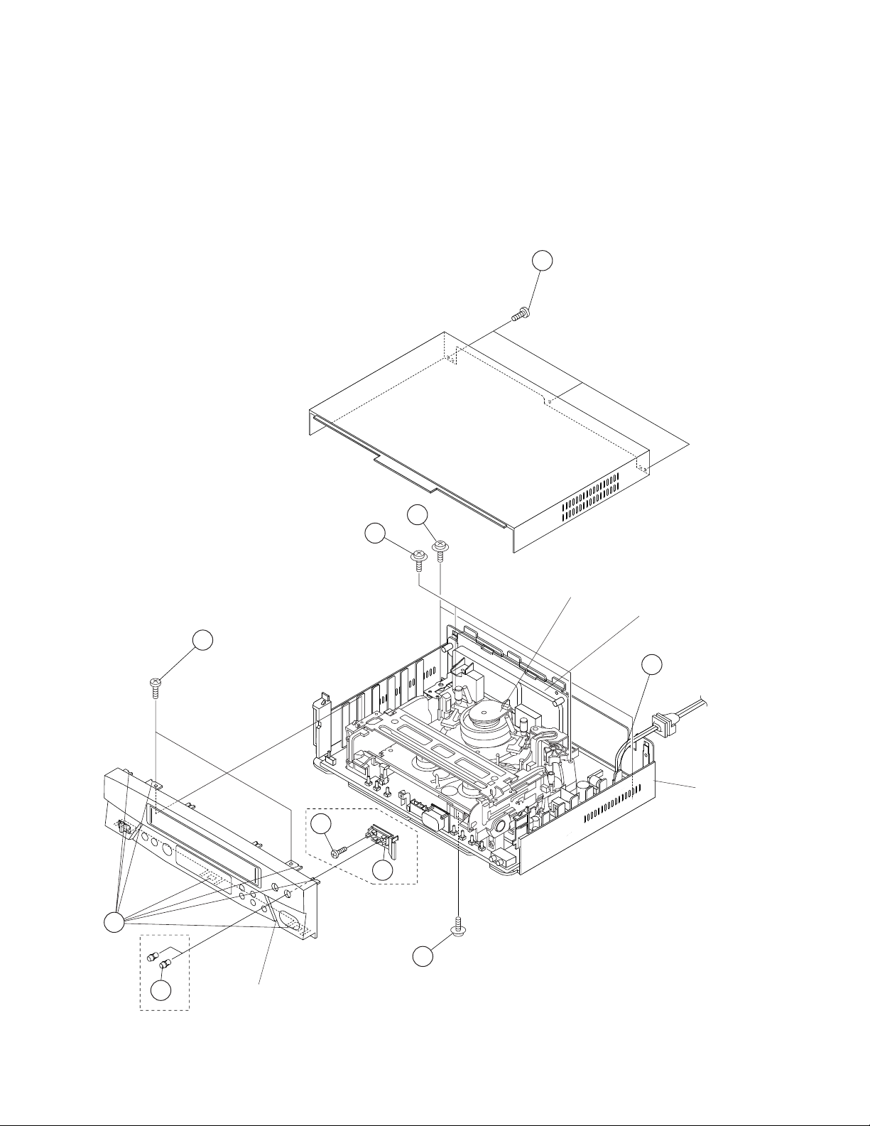
2. DISASSEMBLY AND REASSEMBLY
2-1 DISASSEMBLY OF MAJOR BLOCKS
VC-V10/V19
VC-V30/V50
VC-V59/V70
TOP CABINET : Remove 3 screws 1.
FRONT PANEL : Remove 2 VR Knobs 2 at first(VC-
V30/70). Remove 2 screws 3 and 7
clips 4.
MIC VR PWB : Remove 1 screw 5 and 1 FFC 6.
HOLDER
(VC-V30/70)
XHPSD30P06WS0
XEPSD30P14XS0
7
MECHANISM/ : Remove 2 screws 7 and 2 screws
MAIN PWB Remove 1 screw 9 from behind of the
ASSEMBLY main frame. Remove 1 connector 0.
Lift the antenna terminal cover and take
the assembly out of the main frame.
XEBSD30P12000
1
TOP CABINET
8
8.
MECHANISM/
MAIN PWB
XEBSD30P12000
3
ASSEMBLY
ANTENNA
TERMINAL
COVER
10
MAIN FRAME
5
6
*MIC VR PWB
HOLDER
4
XJPSD30P10WS0
9
2
*MIC VR KNOB
FRONT PANEL
*VC-V30/70 Only
3
Page 4
VC-V10/V19
VC-V30/V50
VC-V59/V70
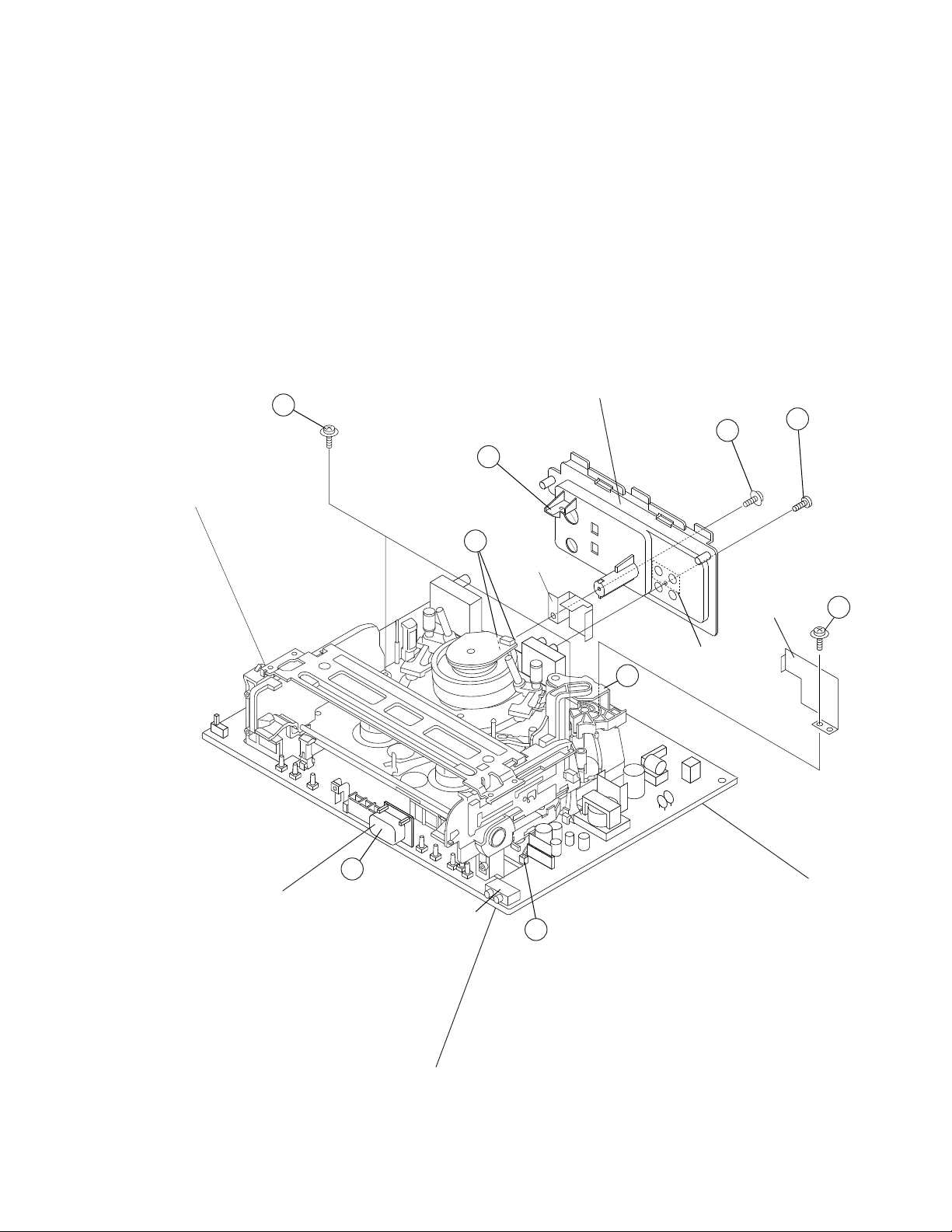
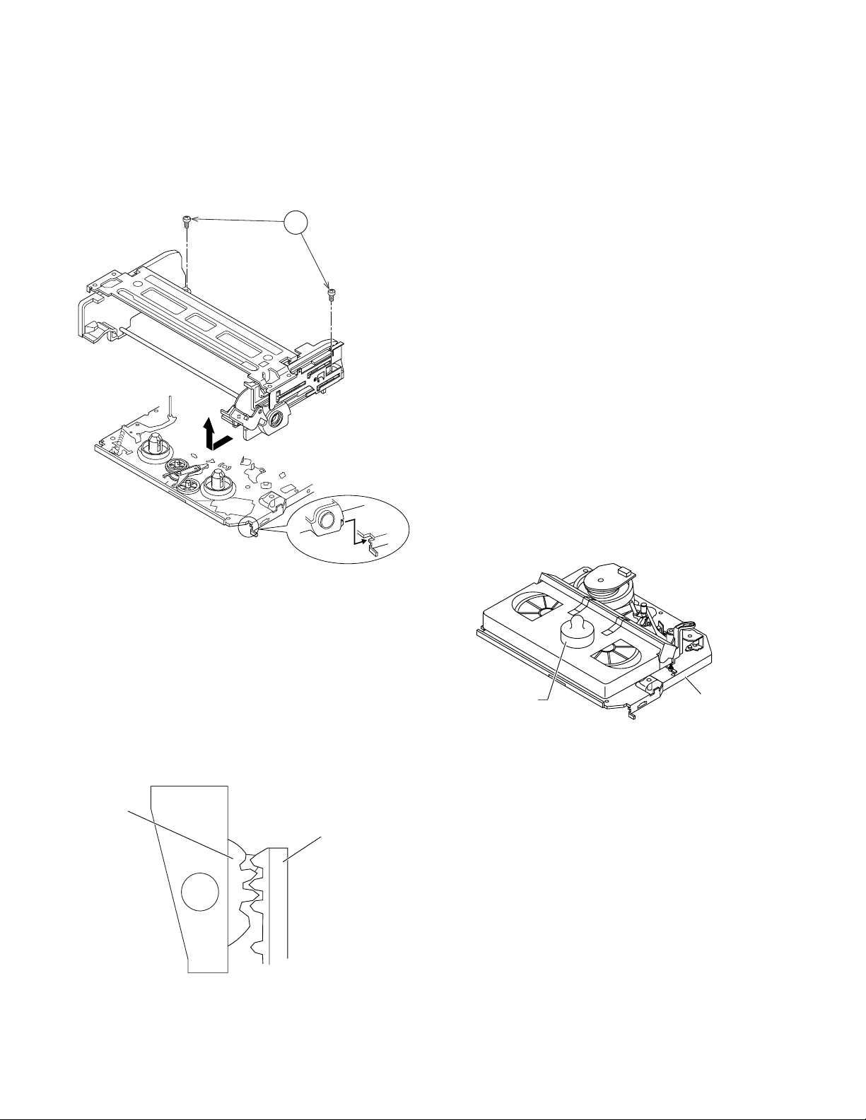
2-2 DISASSEMBLING THE MECHANISM/MAIN PWB ASSEMBLY
ANTENNA : Remove 1 Hook q, 1 screw w and 1
TERMINAL COVER
screw e(VC-V50/59/70 Only).
Remove the H/A shield case.
LED PWB : Take it out of connector r.
HOLDER
MECHANISM : Remove 3 FFCs t and 1 harness y.
CHASSIS/ Be carefull not to confuse the top
CASSETTE and bottom of the FFC.
HOUSING Remove the mechanism chassis assem-
ASSEMBLY bly straight up from the main PWB with
care not to damage theirs urrounding
parts.
XHPSD30P06WS0
17
CASSETTE
HOUSING
CASSETTE : Remove 2 screws u.
HOUSING
SHIELD PLATE : Remove 1 screw i.
ANTENNA
TERMINAL
COVER
LX-HZ3087GEFN
12
11
15
H/A SHIELD
CASE
XEBSD30P12000
VC-V50/59/70 Only
13
LED PWB HOLDER
14
VC-V30/70 Only
16
VC-V50/59/70 Only
15
SHIELD PLATE
MECHANISM
CHASSIS
18
MAIN PWB
4
Page 5
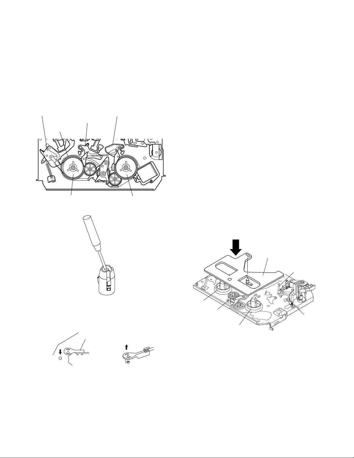
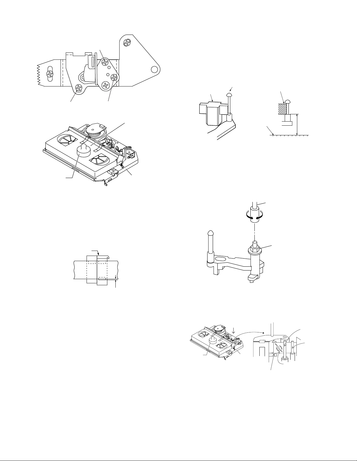
2-3 CARES WHEN REASSEMBLING
VC-V10/V19
VC-V30/V50
VC-V59/V70
INSTALLING THE CASSETTE HOUSING
When the cassette housing is installed on the mechanism,
the initial setting is essential condition.
There are two initial setting methods, namely electrical
and mechanical.
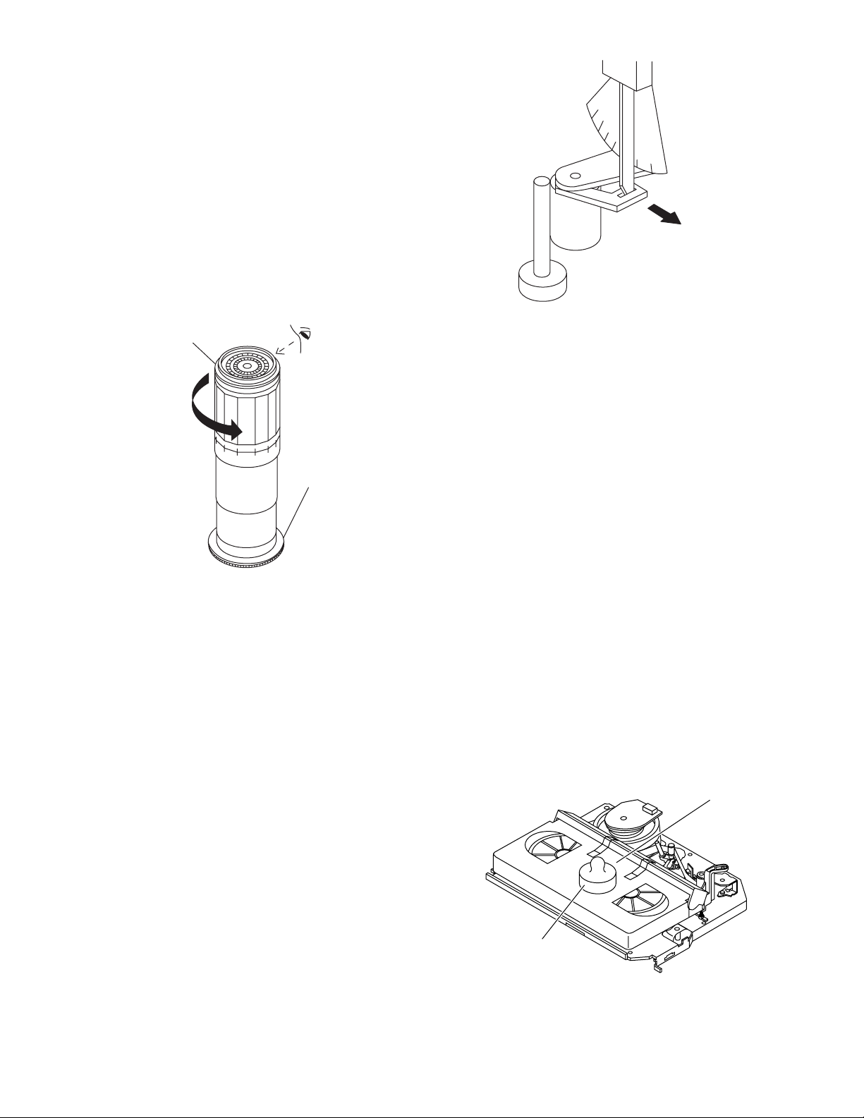
1. Electrical initial setting
So as to perform initial setting of mechanism execute the
Step 1 of Installation of cassette housing. After ascertaining the return to the initial setting position (*1) install the
Pulley feed gear
Screwdriver
Tilt mark (*1)
cassette housing. (Conditions: When mechanism and
PWB have been installed)
2. Mechanical initial setting
Feed the pulley feed gear of loading motor with screw
driver. After ascertaining the return to the initial set position (*1) install the cassette housing in the specified
position. (This method is applied only for the mechanism.)
Casecon
drive gear
Drive angle of
cassette housing
INSTALLING THE MECHANISM ON PWB
Lower vertically the mechanism, paying attention to the
mechanism edge, and install the mechanism with due
care so that the parts are not damaged. So as to fix the
mechanism to the main PWB install two housings. (Fit the
antenna cover to one of them. For other, fix the vicinity of
loading motor and solder joint side of main PWB.) Connect again the FFC cable (AA-MH, AD-ME, AH-MH)
between the mechanism and the main PWB.
END SENSOR
REC TIP SWITCH (VC-V50/59/70 Only)
PARTS WHICH NEED PARTICULAR CARE
When installing the mechanism chassis on the PWB unit,
take care so as to prevent deformation due to contact of
mechanism chassis with REC TIP SW.
AE Connector
AC Connector
AL Connector
START SENSOR
MIC JACK(VC-V30/70 Only)
5
Page 6
VC-V10/V19
VC-V30/V50
VC-V59/V70
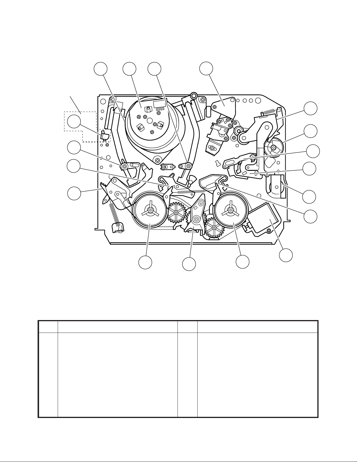
3. FUNCTION OF MAJOR MECHANICAL PARTS (TOP VIEW)
VC-V19/50/59/70
Only
1
2
7
3
1715
18
10
14
9
11
5
12
8
6
No. Function
1 Full erase head(VC-V19/50/59/70 Only)
2 Supply pole base ass’y
3 Tension arm
4 Idler wheel ass’y
5 Pinch drive lever ass’y
6 Supply reel disk
7 Supply main brake
4
No. Function
8 Take-up main brake
9 Pinch drive cam
10 A/C head ass’y
11 Reverse guide lever ass'y
12 Casecon drive gear
13 Take-up reel disk
14 Pinch roller lever ass’y
13
16
6
Page 7
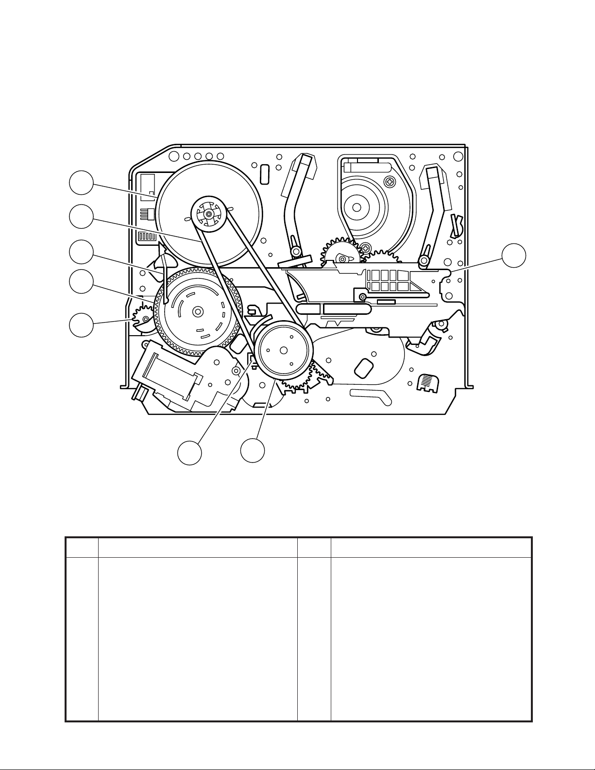
FUNCTION OF MAJOR MECHANICAL PARTS (BOTTOM VIEW)
21
22
VC-V10/V19
VC-V30/V50
VC-V59/V70
19
20
12
23
26
24
No. Function
15 Drum ass’y
16 Loading motor
17 Drum drive motor
18 Take-up pole base ass’y
19 Slow brake lever
20 Master cam
21 Capstan D.D. motor
No. Function
22 Reel belt
23 Clutch lever
24 Limiter pulley ass'y
26 Shifter
7
Page 8
VC-V10/V19
VC-V30/V50
VC-V59/V70
4. ADJUSTMENT, REPLACEMENT AND ASSEMBLY OF MECHANICAL UNITS
The explanation given below relates to the on-site general service (field service) but it does not relates to the adjustment
and replacement which need high-grade equipment, jigs and skill. For example, the drum assembling, replacement and
adjustment service must be performed by the person who have finished the technical courses.
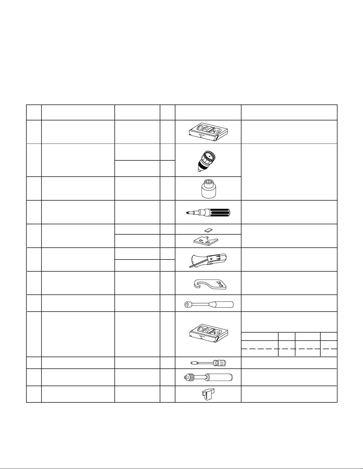
4-1 MECHANISM CONFIRMATION ADJUSTMENT JIG
So as to perform completely the mechanism adjustment prepare the following special jigs. So as to maintain the initial
performance of the machine the maintenance and check are necessary. Utmost care must be taken so that the tape is
not damaged. If adjustment needs any jig, be sure to use the required jig.
No. Jig ltem Part No. Code Configuration Remarks
This cassette torque meter is used for check-
1. Torque Cassette Meter JiGVHT-063 CZ
JiGTG0090 CM
2.
Torque Gauge
JiGTG1200 CN
3. Torque Gauge Head JiGTH0006 AW
ing and adjusting the torque of take-up for
measuring tape back tension.
These Jigs are used for checking
and adjusting the torque of take-up
and supply reel disks.
4. Torque Driver JiGTD1200 CB
Master Plane Jig and
Reel Disk Height
5.
Adjusting Jig
JiGRH0002 BR
JiGMP0001 BY
JiGSG2000 BS
Tension Gauge
6.
JiGSG0300 BF
Pinch pressing force
7. JiGADP003 BK
measuring jig
Reverse guide height
8.
adjustment box driver
Alignment Tape
9.
Guide roller height
10. JiGDRiVERH-4 AP
adjustment driver
X value adjustment
11. JiGDRiVER-6 BM
gear driver
Reverse Guide Height
12. JiGRVGH-F18 BU
Adjusting Jig
JiGDRiVER11055
VROCPSV CK
AR
When fixing any part to the threaded
hole using resin with screw, use the
jig. (Specified torque 5 kg)
These Jigs are used for checking
and adjusting the reel disk height.
There are two gauges used for the
tension measurements, 300 g and
2.0kg.
This Jig is used with the tension
gauge. Rotary transformer clearance
adjusting jig.
This Jig is used for height adjustment of the
reverse guide (for reverse guide height adjustment).
These tape is especially used for
electrical fine adjustment.
Video Audio HiFi Audio Track
625 Monoscope 7k — 49µm
PAL Color Bar 1k — 49 µm
This screwdriver is used for adjusting the
guide roller height.
For X value adjustment
This Jig is used for height
adjustment of the reverse guide.
8
Page 9
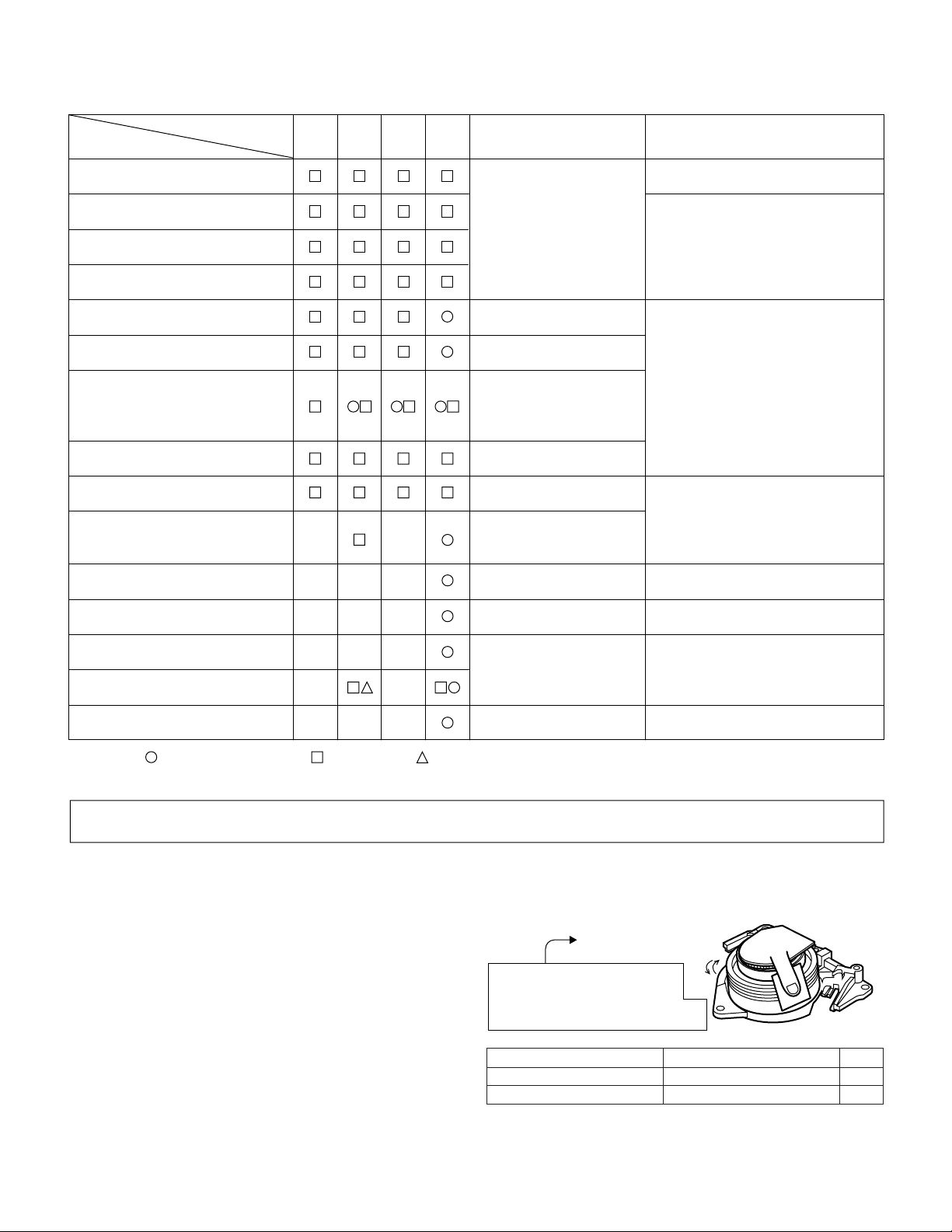
4-2 MAINTENANCE CHECK ITEMS AND EXECUTION TIME
Perform the maintenance with the regular intervals as follows so as to maintain the quality of machine.
VC-V10/V19
VC-V30/V50
VC-V59/V70
Maintained
Parts
Guide roller ass’y
Sup guide shaft
Retaining guide
Slant pole on pole base
Full erase head
A/C head
Upper and lower drum ass’y
Capstan D.D. motor
Pinch roller
Reel belt
Tension band ass’y
500
hrs.
1000
hrs.
1500
hrs
2000
hrs
Possible symptom
encountered
Lateral noises Head
occasionally blocked
Color and beating
Small sound or sound
distortion
Poor S/N ratio, no color
Poor flatness of the
envelope with alignment
tape
No tape running,
uneven color
No tape running, tape
slack
No tape running, tape
slack, no fast forward/
rewind motion
Screen swaying
Remarks
Abnormal rotation or significant
vibration requires replacement.
Clean tape contact part with the
specified cleaning liquid.
Clean tape contact area with the
specified cleaning liquid.
Clean rubber and rubber contact
area with the specified cleaning
liquid.
Loading motor
Idler ass’y
Limiter pulley
Supply/take-up main brake levers
Cassette not loaded or
unloaded
No tape running, tape
slack
Tape slack
NOTE : Part replacement. : Cleaning : Apply grease
<Specified> Cleaning liquid Industrial ethyl alcohol
* This mechanism does not need electric adjustment with variable resistor. Check parts. If any deviation is found,
clean or replace parts.
Video head cleaning procedure
1. Apply one drop of cleaning liquid to the cleaning paper with the baby oiler.
2. Gently press the cleaning paper against the video head to fix your finger, and move the upper drum so that each head
is passed to and fro 5 times (do not move the cleaning paper).
3. Wipe with the dry cleaning paper.
Notes :
• Use the commercially available ethanol of Class 1 as
cleaning liquid.
• Since the video head may be damaged, do not move up
and down the cleaning paper.
Gently press the cleaning paper to
fix with your finger, and rotate the
upper drum to clean.
Move to and fro 5 times for each head.
(Do not move the cleaning paper.)
Rotate the upper drum
with one hand.
• Whenever the video head is cleaned, replace the cleaning paper.
• Do not apply this procedure for the parts other than the
video head.
Parts Code Description Code
ZPAPRA56-001E Cleaning Paper AW
ZOiLR-02-24TE Babe Oiler (Spoit) AH
9
Page 10
VC-V10/V19
VC-V30/V50
VC-V59/V70
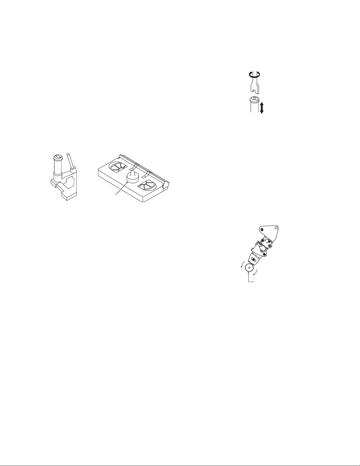
4-3 REMOVING AND INSTALLING THE CAS-
SETTE HOUSING
• Removal
1. In the cassette removing mode, remove the cassette.
2. Unplug the power cord.
3. Remove in the following numerical order.
a) Remove two screws 1.
b) Slide and pull up the cassette housing control.
1
Notes:
1. When fitting the S/E sensor holder to the cassette
controller frame L/R, take care.
2. Misengagement of teeth of casecon drive gear and drive
angle gear causes malfunction. (The cassette cannot be
set, load and ejection are repeated).
3. In the case when you use the magnet screw driver, never
approach the magnet driver to the A/C head, FE head,
and drum.
4. When installing or removing, take care so that the
cassette housing control and tool do not contact the
guide pin or drum.
5. After installing the cassette housing control once perform cassette loading operation.
4-4 TO RUN A TAPE WITHOUT THE CASSETTE
HOUSING CONTROL ASSEMBLY
1. Remove the full-surface panel.
2. Short-circuit TP701.
3. Plug in the power cord.
4. Turn off the power switch.
(The pole bases move into U.L.position.)
5. Open the lid of a cassette tape by hand.
6. Hold the lid with two pieces of vinyl tape.
7. Set the cassette tape in the mechanism chassis.
8. Stabilize the cassette tape with a weight (500g) to
prevent floating.
9. Turn on the power switch.
10. Perform running test.
Figure 4-1.
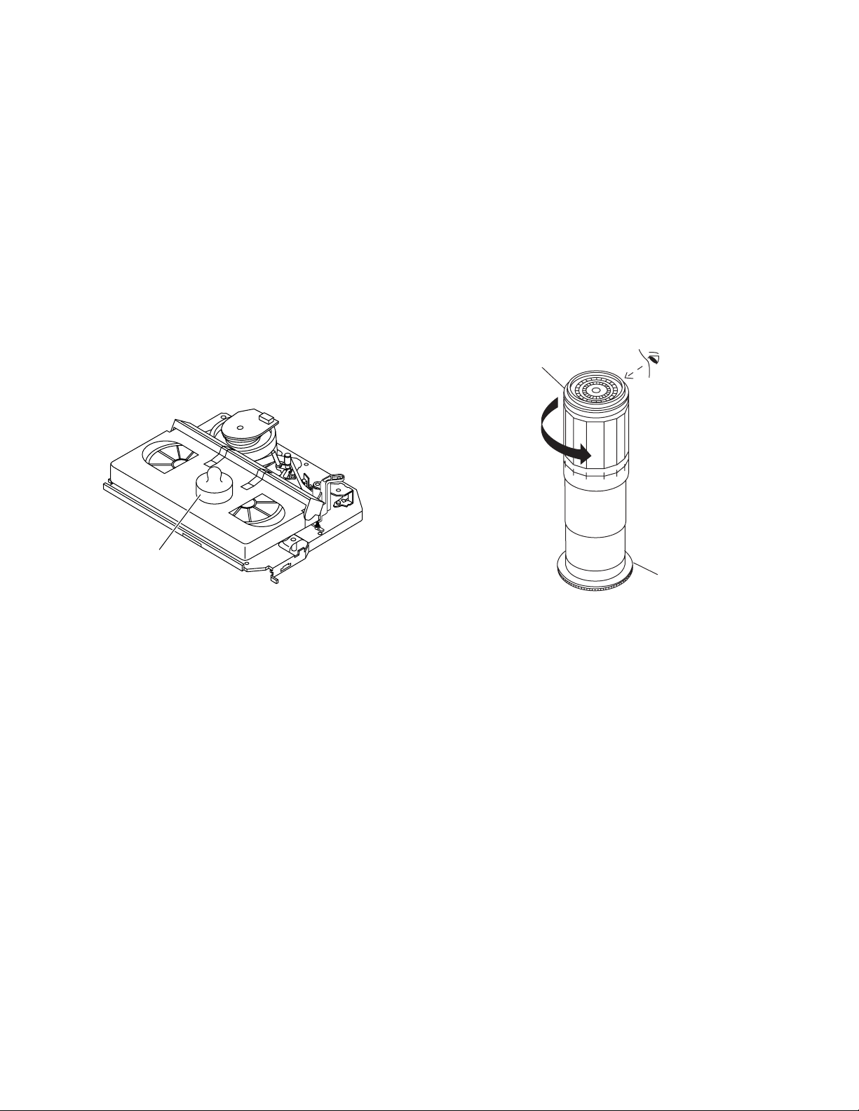
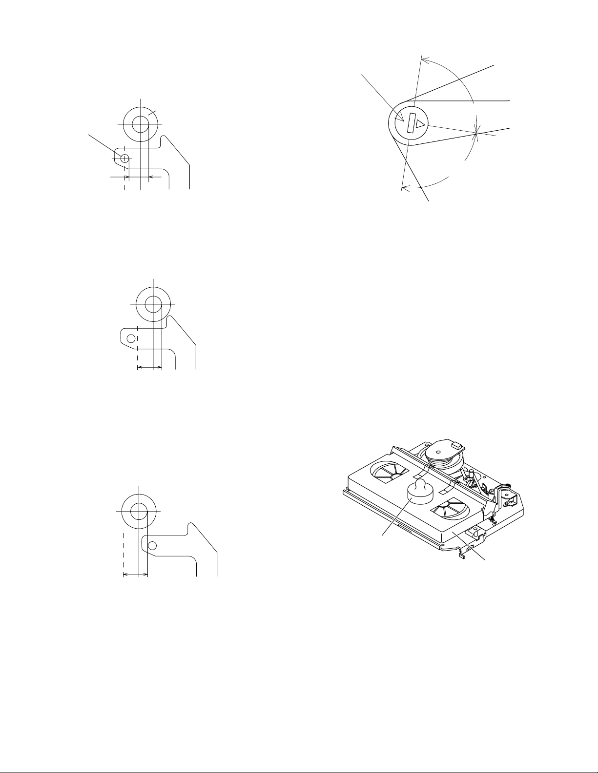
• Reassembly
1. Before installing the cassette housing control, shortcircuit TP701 provided at the center (when facing to the
main PWB), press the eject button. The casecon drive
gear turns and stops when the positioning mark appears. Engage two teeth of casecon drive gear with the
three teeth of casecon drive angle gear, and set on the
mechanism chassis as shown below.
Casecon
drive gear
Casecon drive
angle gear
500g
Weight to prevent
float (500g)
Mechanism chassis
Figure 4-3.
Note:
The weight should not be more than 500g.
To take out the cassette tape.
1. Turn off the power switch.
2. Take out the cassette tape.
Figure 4-2.
2. Install in the reverse order of removal.
10
Page 11
4-5 REEL DISK REPLACEMENT AND HEIGHT
CHECK
• Removal
1. Remove the cassette housing control assembly.
2. Pull the tension band out of the tension arm ass'y.
3. Remove the Supply/Take-up main brake ass'y.
4. Open the hook at the top of the reel disk, and remove the
reel disk.
Note:
Take care so that the tension band ass'y and main brake
ass'y (especially soft brake) are not deformed.
Tension arm ass'y
Supply main brake ass'y
Tension band ass'y
Take-up main brake ass'y
VC-V10/V19
VC-V30/V50
VC-V59/V70
4. Assemble the Supply main brake ass'y.
Notes:
1. When installing the reel disk, take due care so that the
tension band ass'y is not deformed and grease does no
adhere.
2. Do not damage the Supply main brake ass'y. Be careful
so that grease does not adhere to the brake surface.
• Reassembly (Take-up reel disk)
1. Clean the reel disk shaft and apply grease (SC-141) to
it.
2. Align the phase of the reel disk to that of the reel relay
gear and to install a new take-up reel disk onto the shaft.
3. Check the reel disk height and reassemble the take-up
main brake ass'y.
Note:
1. Take care so that the Take-up main brake ass'y is not
damaged. Take care so that grease does not adhere the
brake surface.
2. After reassembly, check the video search rewind back
tension (see 4-10), and check the brake torque (see 4-
14).
Supply reel disk
Take-up reel disk
Figure 4-4.
Note:
When the tension band ass'y is pressed in the direction of
the arrow for removal, the catch is hard to be deformed.
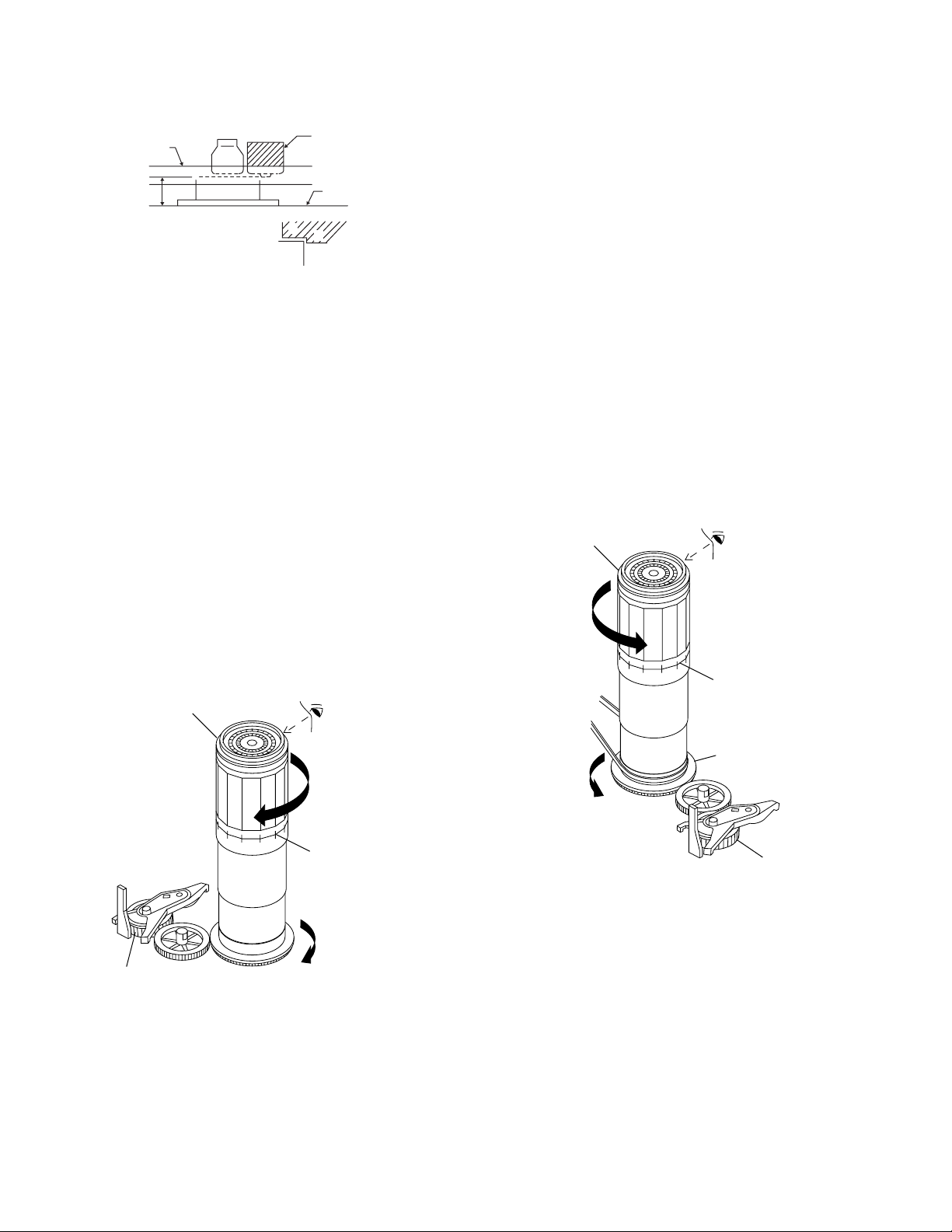
• Height checking and adjustment
Note:
1. Set the master plane with due care so that it does not
contact the drum.
2. When putting the master plane, shift the reverse guide
a little in the loading direction. Care must be taken since
excessive shift results in damage.
Master plane
Reverse
guide
Supply reel disk
Cassette lock
release shaft
Take-up reel disk
Position
pin
Figure 4-6.
Figure 4-5.
• Reassembly (Supply reel disk)
1. Clean the reel disk shaft and apply grease (SC-141) to
it.
2. Match the phases of reel disk and reel relay gear, and set
the new reel disk.
3. After checking the reel disk height, wind the tension
band ass'y around the reel disk, and insert into the hole
of tension arm ass'y.
Note:
• Check that the reel disk is lower than part A but higher
than part B. If the height is not correct, readjust the reel
disk height by changing the poly-slider washer under the
reel disk.
11
Page 12
VC-V10/V19
VC-V30/V50
VC-V59/V70
Note:
Whenever replacing the reel disk, perform the height checking and adjustment.
Master plane
10 ± 0.2mm
Reel disk
Reel disk
Reel disk height
adjusting jig
Mechanism chassis
A
B
Figure 4-7.
4-6 CHECKING AND ADJUSTMENT OF TAKE-
UP TORQUE IN FAST FORWARD MODE
• Remove the cassette housing control assembly.
• After short-circuiting TP701 provided at the center
(facing to the main PWB), plug in the power cord.
• Setting
1. Set a torque gauge to zero on the scale. Place it on the
take-up reel disk.
2. Press the FF button.
3. To calculate the remaining capacity of the play back
mode, slowly rotate the supply reel disk, and then shift
it into the forward mode.
• Checking
1. Turn the torque gauge slowly (one rotation every 2 to 3
seconds) by hand in the CW direction.
2. Make sure that the indication of torque gauge is not less
than 30mN·m (306gf·cm).
Torque gauge
Notes:
1. Hold the torque gauge by hand so that it is not moved.
2. Do not keep the reel disk in lock state. Do not allow longtime measurement.
4-7 CHECKING AND ADJUSTMENT OF TAKE-
UP TORQUE IN REWIND MODE
• Remove the cassette housing control assembly.
• After short-circuiting TP701 provided at the center
(facing to the main PWB), plug in the power cord.
• Setting
1. Set a torque gauge to zero on the scale. Place it on the
supply reel disk.
2. Press the rewind button.
3. To calculate the remaining capacity, slowly rotate the
take-up reel disk, and then shift it into the rewind mode.
• Checking
1. Turn the torque gauge slowly (one rotation every 2 to 3
seconds) by hand in the CCW direction.
2. Make sure that the indication of torque gauge is not less
than 30mN·m (306gf·cm).
Torque gauge
30mN·m (306gf·cm)
or more
CCW
The gauge is held at
its maximum value.
(Red mark)
30mN·m (306gf·cm)
or more
Idler ass'y
CW
The gauge is held at
its maximum value.
(Red mark)
Figure 4-8.
• Adjustment
1. If the FF winding-up torque is less than the specified
value, clean the capstan D.D. motor pulley, drive belt,
and limiter pulley with cleaning liquid, and check again.
2. If the torque is less than the set value, replace the reel
belt.
Supply reel disk
Idler ass'y
Figure 4-9.
• Adjustment
1. If the rewind winding-up torque is less than the specified
value, clean the capstan D.D. motor pulley, drive belt,
and limiter pulley with cleaning liquid, rewind again, and
check the winding-up torque.
2. If the winding-up torque is still out of range, replace the
drive belt.
12
Page 13
Notes:
1. Hold the torque gauge by hand so that it is not moved.
2. Do not keep the reel disk in lock state. Do not allow longtime measurement.
VC-V10/V19
VC-V30/V50
VC-V59/V70
4-9 CHECKING AND ADJUSTMENT OF TAKE-
UP TORQUE IN VIDEO SEARCH REWIND
MODE
• Remove the cassette housing control assembly.
4-8 CHECKING AND ADJUSTMENT OF TAKE-
UP TORQUE IN RECORD/PLAYBACK
MODE
• Remove the cassette housing control assembly.
• After short-circuiting TP701 provided at the center
(facing to the main PWB), plug in the power cord.
• Turn off the power switch.
• Open the cassette torque meter lid, and fix it with
tape.
• Load the cassette torque meter into the unit.
• Put the weight (500g) on the cassette torque meter.
• Turn on the power switch.
• Press the picture record button, and set LP picture
record mode (x2).
Set value LP6.9 ± 2.5mN⋅m (70 ± 25gf⋅cm)
500g
• After short-circuiting TP701 provided at the center
(facing to the main PWB), plug in the power cord.
• Setting
Press the playback button and rewind button to set the
video search rewinding mode.
• Checking
Place the torque gauge on the supply reel disk, and turn it
counterclockwise very slowly (one rotation every 1 to 2
seconds) and check that the torque is within the set value
14.0 ± 3.9mN⋅m. (144 ± 40gf⋅cm)
Torque gauge
CCW
Cassette torque meter
Figure 4-10.
• Checking
1. Make sure that value is within the setting 6.9±2.5mN·m
(70±25gf·cm).
2. The winding-up torque fluctuates due to variation of
rotation torque of limiter pulley ass'y. Read the center
value of fluctuation as setting.
3. Set the LP record mode (x2) and make sure that the
winding-up torque is within setting.
• Adjustment
If the playback winding-up torque is not within the setting,
replace the limiter pulley assembly.
Note:
When the torque cassette is set, put a weight (500g) to
prevent rise.
When the cassette torque meter is taken out.
Turn off the power switch.
Supply reel disk
Figure 4-11.
Note:
Surely put the torque gauge on the reel disk to measure. If
the torque gauge is raised, accurate measurement is
impossible.
• Adjustment
If the rewinding playback winding-up torque is not within the
setting, replace the limiter pulley assembly.
Note:
The winding-up torque fluctuates due to variation of rotation torque of supply reel disk. Read the center value of
fluctuation as setting.
13
Page 14
VC-V10/V19
VC-V30/V50
VC-V59/V70
4-10 CHECKING THE VIDEO SEARCH REWIND
BACK TENSION
• Remove the cassette housing control assembly.
• After short-circuiting TP701 provided at the center
(facing to the main PWB), plug in the power cord.
• Checking
1. After pressing the play button, press the rewind button,
and set the video search rewind mode.
2. Place the torque gauge on the take-up reel disk, and turn
it counterclockwise very slowly (one rotation every 2 to
3 seconds) and check that the torque is within the set
value 3.4±1.5mN⋅m (35± 15gf⋅cm).
Torque gauge
CCW
Take-up reel disk
Pinch roller
Capstan shaft
Tension gauge adapter
Tension gauge
900 - 1,200gf
Figure 4-13.
1. Detach the pinch roller from the capstan shaft.
Do not separate excessively. Or the pinch lever and
pinch double action lever may disengage.
2. Engage the tension gauge adapter with the pinch roller
shaft, and pull in the arrow direction.
3. Gradually return the pinch roller, and measure the
pulling force when the pinch roller contacts the capstan
shaft.
4. Make sure that the measured value is within setting 9.0
to 11.8 N (900 to 1,200gf).
Figure 4-12.
Notes:
Set the torque gauge securely on the take-up reel disk.
If it is not secure, the measurement will be incorrect.
4-11 CHECKING THE PINCH ROLLER PRESSURE
• Remove the cassette housing control assembly.
• After short-circuiting TP701 provided at the center
(facing to the main PWB), plug in the power cord.
• Checking
Press the play button to set the playback mode.
4-12 CHECKING AND ADJUSTMENT OF
TENSION POLE POSITION
• Remove the cassette housing control assembly.
• After short-circuiting TP701 provided at the center
(facing to the main PWB), plug in the power cord.
• Setting
1. Turn off the power switch.
2. Open the cassette tape (E-180), and fix with tape.
3. Set the cassette tape in loading state.
4. Put the weight (500g) on the cassette tape.
5. Turn on the power switch.
6. Make the adjustment with the beginning of a E-180 tape.
(E-180)
500g
Weight to prevent
float (500g)
Figure 4-14.
• Checking
1. Set a cassette tape, push the REC button to place the
unit in the SP record mode. Now check the tension pole
position.
14
Page 15
2. Visually check to see if the right edge of the tension pole
is within the 2.3 ± 0.25 from the right edge of the Sup
guide shaft.
VC-V10/V19
VC-V30/V50
VC-V59/V70
Tension pole adjuster adjusting range
Tension pole adjuster
Sup guide shaft
Tension pole
2.3 ± 0.25
Make the adjustment with the beginning of a E-180 tape.
Figure 4-15.
At left side from the center line
2.3 ± 0.25
Figure 4-16.
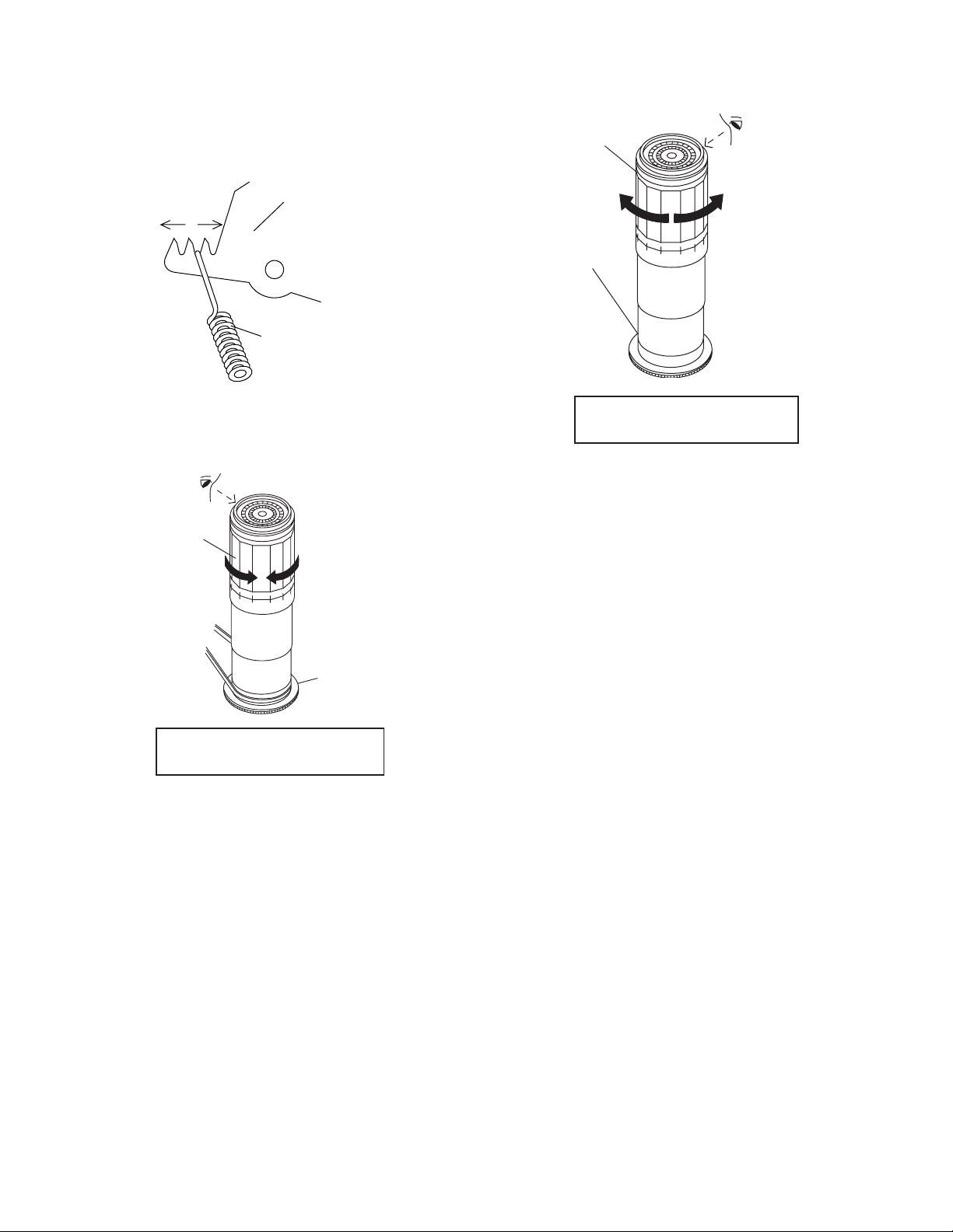
Insert the slotted screwdriver in the tension pole adjuster,
and rotate counterclockwise.
90°
90°
Figure 4-18.
Adjust so that the delta mark of tension pole adjuster is
within 90° range (left, right).
4-13 CHECKING AND ADJUSTMENT OF
RECORD/PLAYBACK BACK TENSION
• Remove the cassette housing control assembly.
• After short-circuiting TP701 provided at the center
(facing to the main PWB), plug in the power cord.
• Setting
1. Turn off the power switch.
2. Open the torque cassette meter and fix with tape.
3. Set the cassette tape in loading state.
4. Put the weight (500g) on the cassette torque meter.
5. Turn on the power switch.
At right side from the center line
2.3 ± 0.25
Figure 4-17.
Insert the slotted screwdriver in the tension pole adjuster,
and rotate clockwise.
500g
Weight to prevent
float (500g)
Cassette torque
meter
Figure 4-19.
• Checking
1. Push the REC button to place the unit in the SP record
mode.
2. At this time ascertain that the back tension is within the
setting (36.5 to 52g·cm) by seeing the indication of
torque cassette meter.
15
Page 16
VC-V10/V19
VC-V30/V50
VC-V59/V70
• Adjustment
1. If the indication of torque cassette meter is lower than
the setting, shift the tension spring engagement to the
part A.
2. If the indication of torque cassette meter is higher than
the setting, shift the tension spring engagement to the
part B.
A
B
Tension arm
Tension spring
• Checking the brake torque at the take-up side
Torque gauge
CW
Take-up reel
disk
CCW
Figure 4-20.
4-14 CHECKING THE BRAKE TORQUE
• Checking the brake torque at the supply side
Torque gauge
CCW
CCW: 2.9~9.8mN⋅m (30~100gf⋅cm)
CW: 4.9~13.7mN⋅m (50~140gf⋅cm)
Figure 4-21.
• Remove the cassette housing control assembly.
• After short-circuiting TP701 provided at the center
(facing to the main PWB), plug in the power cord.
• Setting
1. Set a torque gauge to zero on the scale. Place it on the
supply reel disk.
2. Switch from the FF mode to the STOP mode.
3. Disconnect the power cord.
• Checking
Turn the torque gauge at a rate of about one turn/2 sec
in the CW direction/CCW direction with respect to the
supply reel disk so that the reel disk and torque gauge
pointer rotate at equal speed, and make sure that the
value is within the setting (CW direction: 4.9 to 13.7mN·m
(50 to 140gf·cm); CCW direction: 2.9 to 9.8mN·m (30 to
100gf·cm).
CW
Supply reel disk
CCW: 4.9~13.7mN⋅m (50~140gf⋅cm)
CW: 3.9~10.8mN⋅m (40~110gf⋅cm)
Figure 4-22.
• Remove the cassette housing control assembly.
• After short-circuiting TP701 provided at the center
(facing to the main PWB), plug in the power cord.
• Setting
1. Switch from the FF mode to the STOP mode.
2. Disconnect the power cord.
3. Set a torque gauge to zero on the scale. Place it on the
take-up reel disk.
• Checking
1. Turn the torque gauge at a rate of about one turn/2 sec
in the CCW direction/CW direction so that the reel disk
and torque gauge pointer rotates at equal speed and
make sure that the value is within the setting (CCW
direction: 4.9 to 13.7mN·m (50 to 140gf·cm), CW direction: 3.9 to 10.8 mN·m (40 to 110gf·cm).
2. Adjustment of the brake torque at the supply side and the
take-up side
• Unless the supply side brake torque or take-up side
brake torque is within the setting, clean the felt surface
of reel disk (supply, take-up) brake lever, check again
the brake torque.
• If value cannot be set within the setting yet, replace the
main brake ass'y or main brake spring.
16
Page 17
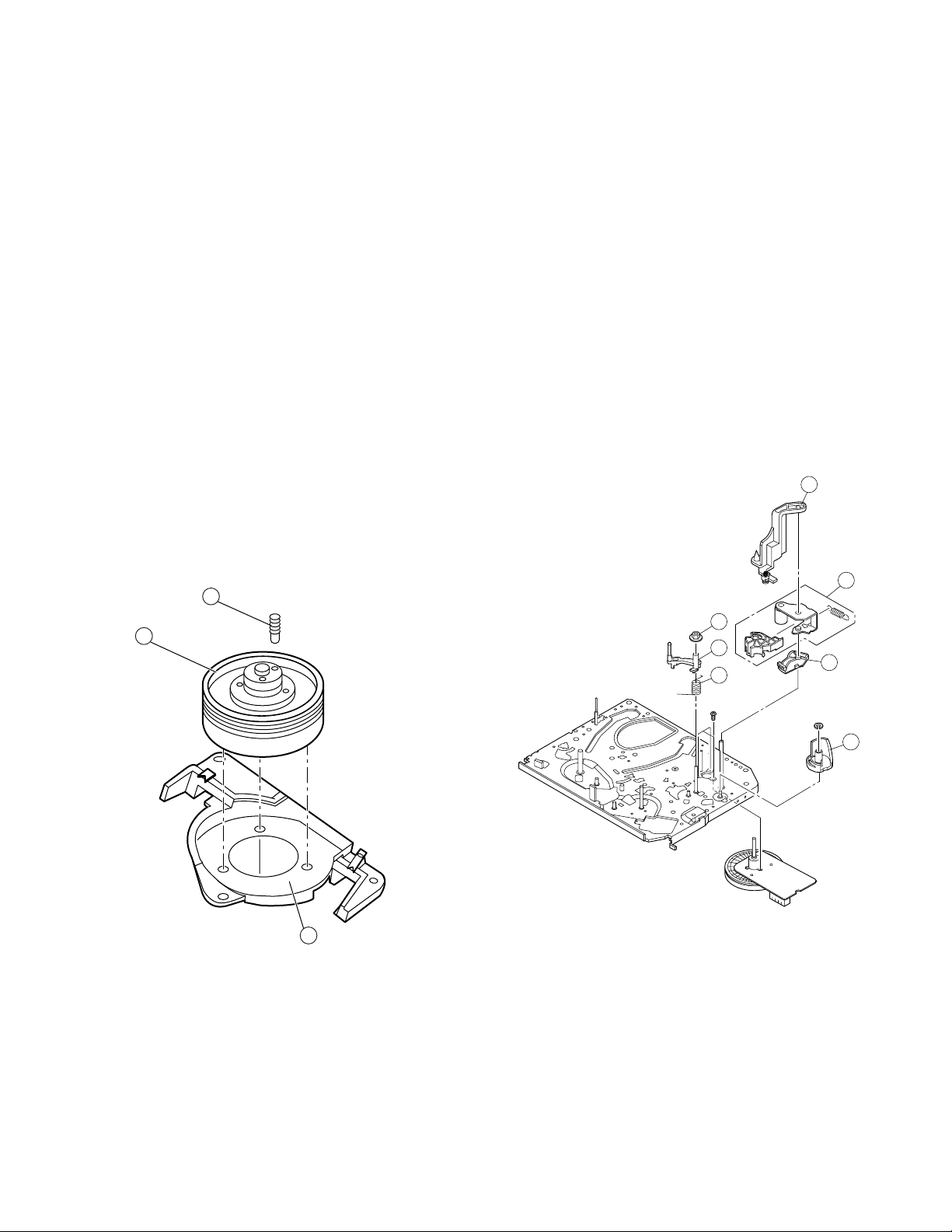
4-15 REPLACEMENT OF A/C (Audio/Control)
HEAD
1. Remove the cassette housing control assembly.
2. In unloading state unplug the power cord.
• Removal
1. Remove the screws 123, Azimuth screw, Tilt screw.
2. Unsolder the PWB fitted to the A/C head.
Notes:
1. When replacing, never touch the head. If you touched,
clean with the cleaning liquid.
2. When removing the screw 3, take care so that the
spring may out.
Tilt screw
3
Azimuth screw
Height screw
Spring
1
VC-V10/V19
VC-V30/V50
VC-V59/V70
3. Align the left end of gear of A/C head arm with the
punched mark of chassis, tentatively tighten the screws
1 and 2 so as to ensure smooth motion of A/C head
arm. Tentative tightening torque must be 0.15 to 0.20
N·m (1.5 to 2.0kgf·cm).
1
3
Height screw
Left end of A/C head arm gear
2
Punched line mark on chassis
Figure 4-25.
Note:
1. If the screws 1 and 2 are tighten tentatively too loose,
the azimuth and height of A/C head may change when
they are finally tightened. Therefore care must be taken.
2. After completion of A/C head be sure to adjust tape
running. (Execute the running adjustment by the method
described in 4-18.)
2
Figure 4-23.
• Replacement
1. Solder the removed PWB to the new head assembly.
2. Adjust the height from the A/C head arm (lower surface)
to the A/C head plate to 10.8mm with slide calipers. (3
places of azimuth screw section, tilt screw section and A/
C head front section) (See the figure below.)
Solder
New A/C head ass'y
A/C head PWB
Never touch the head
A/C head plate
Figure 4-24.
10.8mm10.8mm
17
Page 18
VC-V10/V19
VC-V30/V50
VC-V59/V70
4-16 A/C HEAD HEIGHT ROUGH ADJUSTMENT
• Setting
Azimuth screw
4-17 HEIGHT ADJUSTMENT OF REVERSE
GUIDE
1. Adjust the height from the mechanism chassis to the
reverse guide lower flange to 13.38 mm, using the
reverse guide height adjustment jig, in tape loading
state. (Refer to Figure 4-28 (a) (b).)
Height screw
500g
Weight to prevent
float (500g)
Tilt screw
Cassette tape
Mechanism chassis
Figure 4-26.
1. Set the cassette tape in the unit.
2. Press the PLAY button to put the unit in the playback
mode.
3. Roughly adjust the height of the A/C head by turning the
height screw until the tape is in the position shown
below.
A/C head
Reverse guide
Reverse guide height
adjusting jig
Mechanism
chassis
(a)
Reverse guide height
adjusting jig
13.38mm
(b)
Figure 4-28.
2. Rotate counterclockwise the reverse guide height adjustment nut 1/10 turn. (For height adjustment use the
reverse guide height adjustment box driver (JiGDRiVER
11055)).
Box driver
CCW
Height adjusting nut
Tape
0.3mm
Figure 4-27.
• Adjustment
Adjust the height screw visually so that the control head is
visible 0.3mm below the bottom of the tape.
Figure 4-29.
3. Set the tape, and check for tape crease near the reverse
guide in the playback mode.
If crease is found, turn the reverse guide adjustment nut
to remove crease. (As for crease check refer to Figure 4-
30.)
500g
Weight to
prevent float (500g)
A
Mechanism
chassis
Reverse guide
Capstan
motor shaft
Fixing guide
An example of
crease near the
reverse guide
* Check for crease from the A direction.
Figure 4-30.
18
Page 19
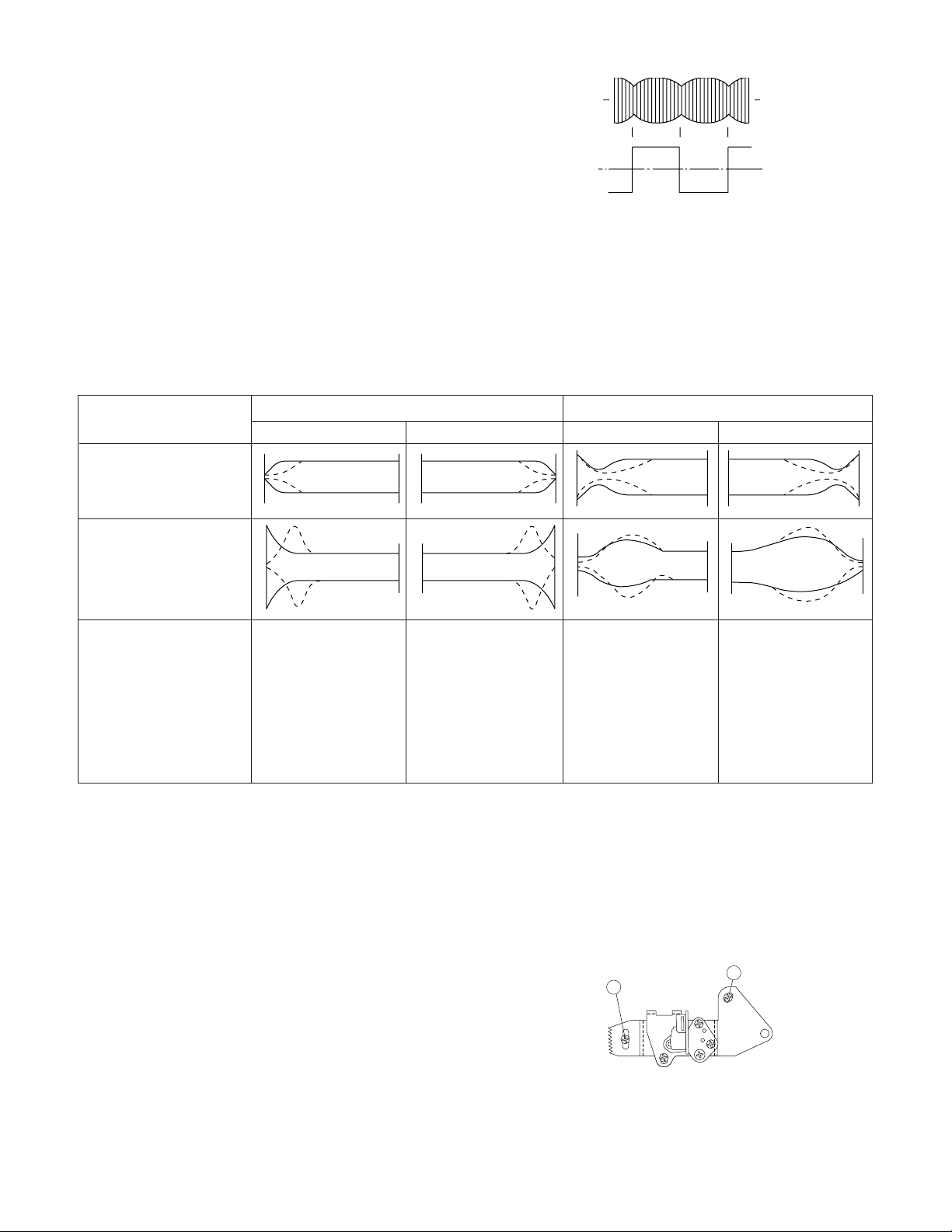
4-18 ADJUSTMENT OF TAPE DRIVE TRAIN
1. Tape run rough adjustment
1 Remove the cassette housing control assembly.
2 After shortcircuiting TP701 provided at the center
(facing to the main PWB), plug in the power cord.
3 Check and adjust the position of the tension pole.
(See 4-12.)
4 Check and adjust the video search rewind back
tension. (See 4-10.)
5 Connect the oscilloscope to the test point for PB
CHROMA envelope output (TP201). Set the synchronism of the oscilloscope to EXT. The PB
CHROMA signal is to be triggered by the head
switching pulse (TP202).
6 Set the alignment tape (VROCPSV) to play. (Put a
500g weight on the cassette tape to prevent lift of
cassette tape.)
Guide roller
Cassette Tape
500g
Weight of 500g
Figure 4-31.
7 Press the tracking button (+), (–) and change the
envelope waveform from max to min and from min to
max. At this time make sure that the envelope
waveform changes nearly parallel.
8 Unless the envelope waveform changes nearly par-
allel, adjust the height of supply side and take-up
side guide roller so that the envelope waveform
changes nearly parallel. (For envelope adjustment
procedure refer to Figure 4-35.)
9 Turn the tilt screw to remove the tape crease at the
fixing guide flange.
Playback the tape and check for tape crease at the
fixing guide flange.
(1)If there is no tape crease
Turn the tilt screw clockwise so that tape crease
appears once at the flange, and then return the tilt
screw so that the crease disappears.
(2)If there is tape crease
Turn counterclockwise the tilt screw so that the
tape crease disappears.
(Reference) If the tilt screw is turned clockwise
crease appears at the lower flange.
VC-V10/V19
VC-V30/V50
VC-V59/V70
Notes:
1. Previously set the tracking control in the center position,
and adjust the envelope waveform to maximum with X
value adjustment nut. Thereby the tape run rough adjustment is facilitated.
2. Especially the outlet side envelope waveform must have
higher flatness.
Figure 4-32.
2. Adjustment of A/C head height and azimuth
1 Perform the initial setting of A/C head position by the
method stated in "4-15 Replacement 3".
2 Connect the oscilloscope to the audio output termi-
nal.
3 Using the alignment tape in which 1 kHz linear audio
signal has been recorded, adjust the height screw so
as to get max audio output.
4 Using the alignment tape in which 7 kHz linear audio
signal has been recorded, adjust the azimuth screw
so as to get max audio output.
5 The adjustment of 3 and 4 twice or three times
repeat, and finally adjust 4.
For X value adjustment
Adjust the X value, turning the geartype screwdriver.
Figure 4-33.
3. Tape run adjustment
1 Connect the oscilloscope to PB CHROMA envelope
output test point, set oscilloscope sync to EXT,
trigger-input the PB CHROMA signal (head switching pulse).
2 Rough adjustment of X value
Tentatively fix A/C head arm screws 1 and 2 by the
method described in 4-15 "Replacement 3".
Playback the alignment tape (VROCPSV).
Move the A/C head with the X value adjustment gear
driver (JiGDRiVER-6) by the method shown in Figure 4-33, and adjust the A/C head so as to get the
maximum envelope waveform. (Note: When the A/
C head is adjusted, adjust so that the maximum
envelope waveform is obtained nearest the position
of initial setting made in 4-15.)
19
Page 20
VC-V10/V19
VC-V30/V50
VC-V59/V70
3 Next, press the tracking button (+), (–) and change
4 If the tape is lifted or sunk from the helical lead
5 Press the tracking button (+), (–) and make sure that
6 Finally check tape crease near the reverse guide. If
the envelope waveform from max to min and from
min to max. At this time adjust the height of supply
and take-up side guide roller with the adjustment
driver (JiGDRiVERH-4) so that the envelope waveform changes nearly parallel.
surface, the PB CHROMA envelope waveform appears as shown in Figure 4-35.
the envelope waveform changes nearly parallel.
tape crease is found, remove it as stated in 4-17
"HEIGHT ADJUSTMENT OF REVERSE GUIDE"
item 3.
Supply side
Take-up side Supply side Take-up side
PB CHROMA
Envelope
CH-1 CH-2
Head switching pulse
Figure 4-34.
4. A/C head X value adjustment
1 Tentatively fix A/C head arm screws 1 and 2 by the
method described in 4-15 "Replacement 3".
2 Playback the alignment tape (VROCPSV).
When the tape is below the helical lead.When the tape is above the helical lead.
Adjustment
Supply side guide roller
rotated in clockwise
direction (lowers guide
roller) to flatten
envelope.
Take-up side guide roller
rotated in clockwise
direction (lowers guide
roller) to flatten
envelope.
Figure 4-35.
3 Move the A/C head with the X value adjustment gear
driver by the method shown in Figure 4-33, and
adjust the A/C head so as to get the maximum
envelope waveform. (Note: At this time adjust so as
to get the maximum envelope waveform nearest the
A/C head position which has been set in case of X
value rough adjustment as stated in 4-18, 3- 2.)
4 Tighten finally the screws 1 and 2. Be sure to
tighten at first the screw 1 and then the screw 2.
Final tightening torque is 0.6N·m (If the screw 2 is
tightened first, the X value may deviate.)
5 Adjust the playback switching point (Refer to the
electric adjustment method.)
6 Playback the self-picture-recorded tape, and check
the flatness of envelope waveform and sound.
Supply side guide roller
rotated in counterclockwise direction (raises
guide roller) to make the
tape float above the helical
lead. The supply
side guide roller is then
rotated in the clockwise
direction to flatten the
envelope.
Take-up side guide roller
rotated in counterclockwise direction (raises
guide roller) to make the
tape float above the
helical lead. The take-up
side guide roller is then
rotated in the clockwise
direction to flatten the
envelope.
Notes:
When the A/C head X value adjustment is performed, be
sure to perform at first X value rough adjustment (refer to 4-
18, 3-2).
2
1
Figure 4-36.
20
Page 21
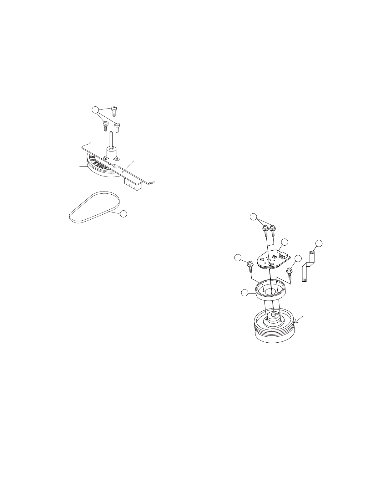
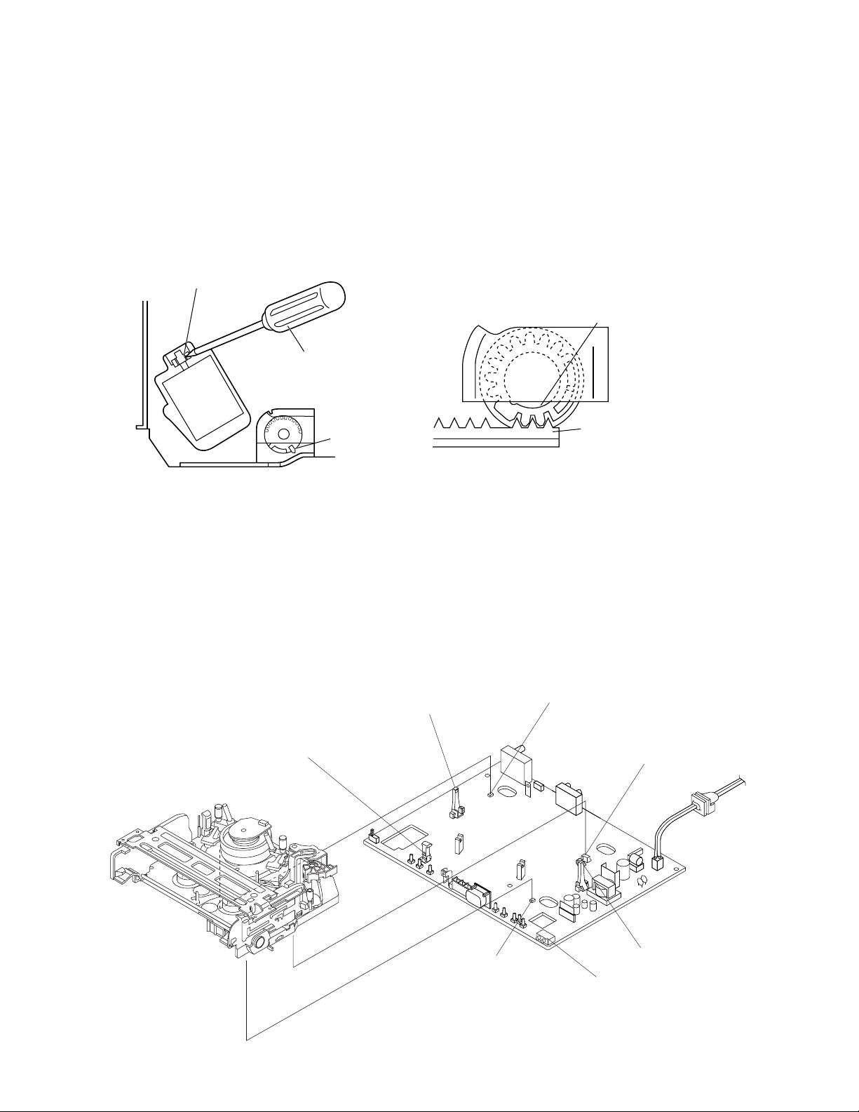
4-19 REPLACEMENT OF THE CAPSTAN D.D.
(DIRECT DRIVE) MOTOR
• Remove the mechanism from the main PWB (refer to 22 item 1. When removing the mechanism from the main
PWB").
• Removal (Follow the order of indicated numbers.)
1. Remove the reel belt 1.
2. Remove the three screws 2.
VC-V10/V19
VC-V30/V50
VC-V59/V70
4-20 REPLACEMENT OF DRUM D.D. MOTOR
1. Set the ejection mode.
2. Withdraw the main power plug from the socket.
• Removal (Perform in numerical order.)
1. Disconnect the FFC cable 1.
2. Unscrew the D.D. stator assembly fixing screws 2.
3. Take out the D.D. stator assembly 3.
4. Unscrew the D.D. rotor assembly fixing screws 4.
5. Take out the D.D. rotor assembly 5.
2
Capstan D.D. motor
1
control PWB
Reel belt
Capstan D.D.
motor
Figure 4-37.
• Reassembly
1. Taking care so that the capstan shaft does not contact
the mechanism chassis, set its position on the mechanism chassis, and then install with the three screws.
2. Install the reel belt.
Notes:
1. After installing the capstan D.D. motor, be sure to rotate
the capstan D.D. motor and check the movement.
2. Set the tape, and check for the tape crease near the
reverse guide in the playback mode. Adjust the A/C
head and azimuth as stated in 4-18 item 2. If crease is
found, adjust as stated in 4-17 "HEIGHT ADJUSTMENT
OF REVERSE GUIDE".
Notes:
1. In removing the D.D. stator assembly, part of the drum
earth spring pops out of the pre-load collar.
Be careful not to lose it.
2. Install, so that the D.D. rotor ass'y and upper drum ass'y
mounting direction check holes align.
(Align the upper drum dent with the rotor hole.)
3. Be careful not to damage the upper drum or the video
head.
4. Protect the hole elements from shock due to contact with
D.D. stator or D.D. rotor ass'y.
5. After installation adjust the playback switching point for
adjustment of servo circuit.
2
D.D. stator ass'y
3
4
5
4
D.D. rotor ass'y
1
FFC
Upper drum
21
Figure 4-38.
Page 22
VC-V10/V19
VC-V30/V50
VC-V59/V70
4-21 REPLACING THE UPPER AND LOWER
DRUM ASSEMBLY
• Replacement (Perform in the numerical order)
1 Remove the motor as stated in 4-20.
2 Remove the drum earth brush ass’y 2.
3 Remove the drum base 3 from the upper and lower
drum assembly 1.
[Cares when replacing the drum]
1. Be careful so that the drum earth brush is not lost.
2. Do not touch directly the drum surface.
3. Fit gently the screwdriver to the screws.
4. Since the drum assembly is an extremely precise assembly, it must be handled with utmost care.
5. Make sure that the drum surface is free from dust, dirt
and foreign substances.
6. After replacing the drum be sure to perform the tape
running adjustment.
After that, perform also the electrical adjustment.
• Playback switching point adjustment
• X-position adjustment and check
• Standard and x-3 slow tracking adjustment
7. After replacing the drum clean the drum.
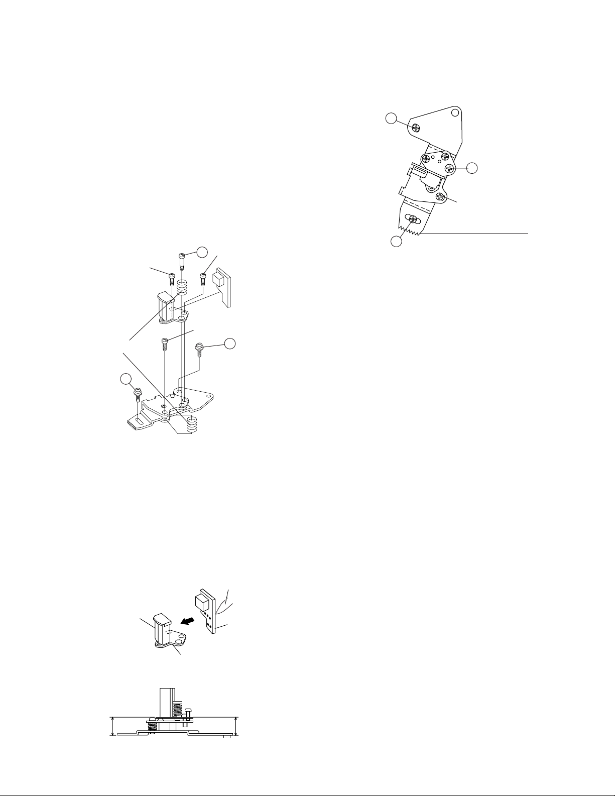
4-22 ASSEMBLING OF PHASE MATCHING
MECHANISM COMPONENTS
• Assemble the phase matching mechanism components in the following order.
1. Assemble the pinch roller assembly and pinch drive
cam.
2. Mounting the shifter (on the back of the mechanism
chassis).
3. Mounting the master cam (on the back of the mechanism chassis).
4. Assemble the connection gear, slow brake and loading
motor parts.
• Pinch drive cam and pinch roller assembling
method.
(Place the following parts in position in numerical order.)
(1)Reverse drive lever 1
(2)Reverse guide spring 2
(3)Reverse guide lever ass’y 3
(4)Reverse guide height adjusting nut 4
(5)Pinch drive cam 5
(6)Pinch roller ass’y 6
(7)Open lever 7
7
6
2
1
3
Figure 4-40.
4
3
1
2
5
Figure 4-39.
22
Page 23
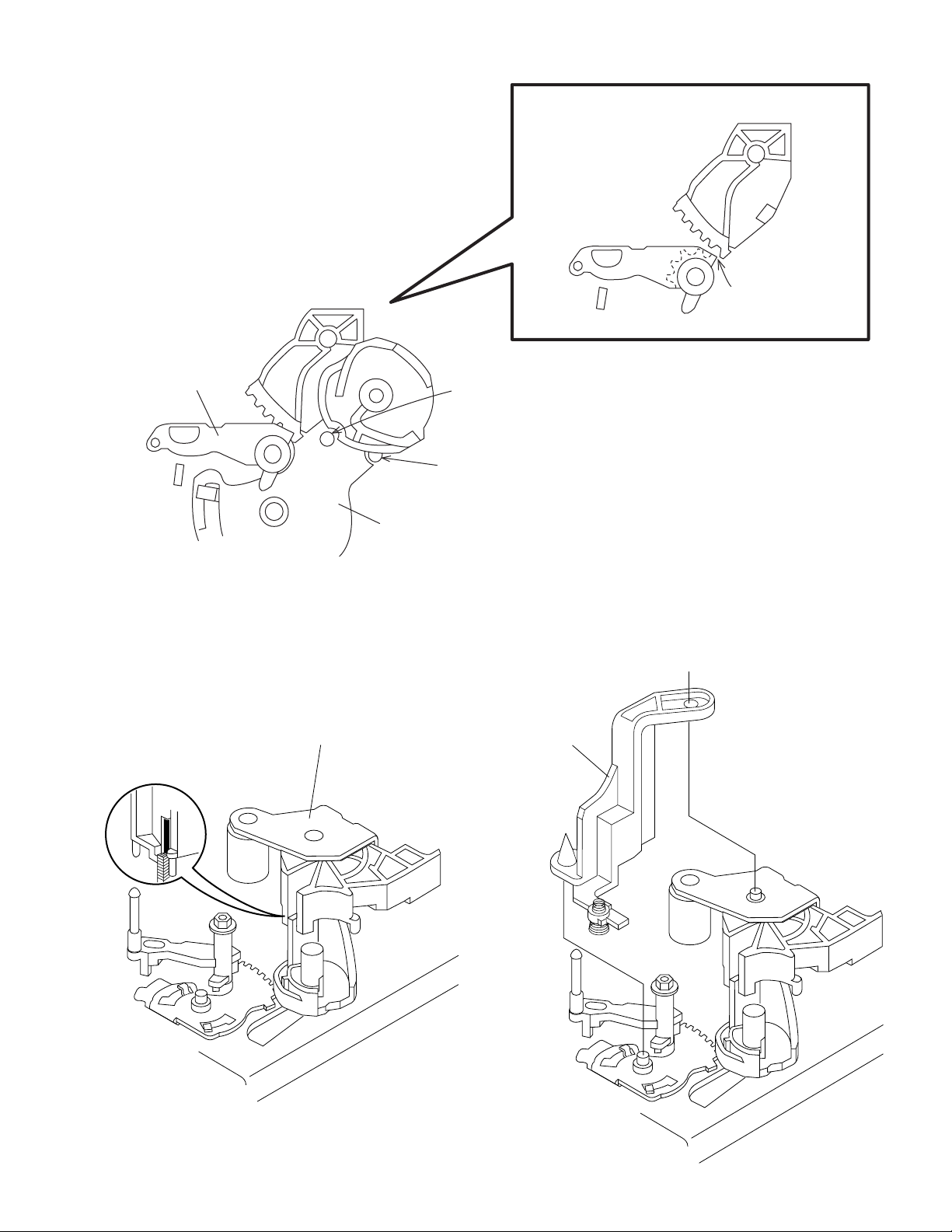
1Insert Reverse Guide Lever Ass’y
VC-V10/V19
VC-V30/V50
VC-V59/V70
Insert reverse guide lever ass'y
2 Insert pinch drive cam
Turn the reverse guide lever
assembly counterclockwise
to the stopper.
Fit the pinch drive cam so that the notch of
pinch drive lever assembly aligns with the
half-round notch of chassis.
Pinch drive lever ass'y
Figure 4-41-1.
2Insert Pinch Roller/Pinch Double Action Lever Ass’y.
Pinch Roller Double
Action Lever Ass'y
Phase Matching Point 2
Align here.
Fit the pinch drive cam so that the notch of pinch
drive cam aligns with the dent of pinch drive lever
assembly.
3Insert Open Lever.
Open lever
Figure 4-41-2.
Figure 4-41-3.
23
Page 24
VC-V10/V19
VC-V30/V50
VC-V59/V70
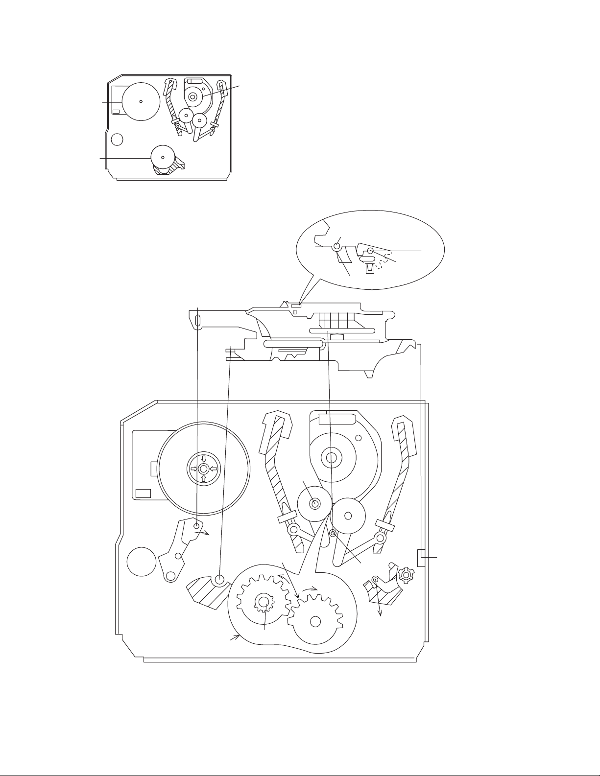
4-23 INSTALLING THE SHIFTER
Capstan
D.D. motor
Reel pulley
Drum
1. Make sure that the loading gear is at the Phase-Matching point 1 as shown below.
2. Install, paying attention to insert point 5 and release
point 3.
3. For the phase matching at the insert point 1, see the
Phase-Matching point 2 as shown below.
4. Finally fix the inserts 1 and 4.
(Bottom side of mechanism chassis)
Figure 4-42.
Insert
point 3
Insert
point 2
Shaft 1
Phase-Matching
point 2
Round mark
Sifter
Loading gear (T)
Insert
point 1
Shaft 1
Half round notch
Insert
point 4
Phase-matching
point 1
Rotation
point 2
Shaft 1
Figure 4-43.
24
Shaft 4
Release
point 3
Insert
point 5
Page 25

4-24 INSTALLING THE MASTER CAM (AT
REAR SIDE OF MECHANISM CHASSIS)
1. Make sure beforehand that the shifter is at the point as
shown below.
2. Place the master cam in the position as shown below.
E ring
(XRESJ30-06000)
Master cam
Fully turn
clockwise
Fully turn counterclockwise
VC-V10/V19
VC-V30/V50
VC-V59/V70
4-25 REPLACEMENT OF LOADING MOTOR
• Removal
Apply grease
Apply grease
Face the wide tooth side ward
Figure 4-44-1.
Note:
See the figure below for the phase matching between the
master cam and the casecon drive gear.
3. Finally fix with the E ring.
Master cam
Casecon drive gear
Half-round notch
Round mark
When installing the master cam,
align the casecon drive gear
round mark with the half-round
notch of master cam.
No grease
Figure 4-45.
• Replacement
Remove the loading motor, and install the replacement
loading motor as shown below.
+0.2
10.2 mm
–0.2
Figure 4-44-2.
Figure 4-46.
The loading motor pressing-in must be less than 14.7 N
(1500 gf).
Adjust the distance between motor and pulley to 10.2
+0.2
mm).
–0.2
25
Page 26

VC-V10/V19
VC-V30/V50
VC-V59/V70
4-26 ASSEMBLY OF CASSETTE HOUSING
1. Drive Gear and R Drive angle ass’y
Apply grease
2. Synchro Gear, Drive Gear L and Drive Gear R
MSPRT0381AJFJ
Apply grease
Apply grease
Figure 4-47.
Top surface should be free from scratches or soil.
Drive angle
LANGF9592AJFW
Drive gear R
Frame
Figure 4-48.
26
Page 27

5. ELECTRICAL ADJUSTMENT
Notes:
• Before the adjustment:
Electrical adjustments discussed here are often required after replacement of electronic components and mechanical
parts such as video heads.
Check that the mechanism and all electric components are in good working condition prior to the adjustments,
otherwise adjustments can not be completed.
• Instruments required:
Colour TV monitor Dual-trace oscilloscope
Audio signal generator AC milli-voltmeter
Blank video cassette tape Alignment tape (VROCPSV)
Screwdriver for adjustment
Colour bar signal generator
• Location of controls and test points
T601
VC-V10/V19
VC-V30/V50
VC-V59/V70
P201
(TP202-3)
TP701-2
R875
Figure 5-1.
27
Page 28

VC-V10/V19
µ
VC-V30/V50
VC-V59/V70
SERVO CIRCUIT ADJUSTMENT
ADJUSTMENT OF HEAD SWITCHING POINT
Measuring
instrument
Mode
Cassette
Test point VIDEO OUT jack to CH2
Control
Specification
1. Remove the front panel.
2. Set the COLOUR MODE switch turn on the PAL AUTO
mode, and play the alignment tape.(VROCPSV)
3. Connect a dual-trace oscilloscope to the VIDEO OUT
jack and TP202(H.S.P.)~TP203(GND).(Trigger the oscilloscope with the head switching pulse on TP202)
4. Playback the alignment tape, and then short circuit
between TP701 and TP702 on the main PWB, and press
both TRACKING buttons (+) and (–) on the remote
control at same time.
Be sure that the S.S. Picture LED flashing(about 2Hz)
into the TEST mode.
5. Cancel the short circuited of step-4.
6. Adjust R875 so that the leading edge of the head switching pulse is 6.5H (lines) a head of the vertical sync as
shown in Figure 5-2.
7. Press the STOP button in the return to normal mode.
Note:
When the models with both of PAL and NTSC function,
make of adjustment at PAL mode only.
Dual-trace oscilloscope
Playback
Alignment tape(VROCPSV)
TP202(H.SW.P.)~TP203(GND)
to CH1
R875 Head switching point
adjustment control
6.5 ± 0.5H (lines)
ADJUSTMENT OF FV (False Vertical Sync) OF
STILL PICTURE
Measuring
instrument
Mode
Cassette
Control Tracking control buttons (+) or (–)
Specification No vertical jitter of picture
1. Play an Alignment tape or a self-recorded tape.
2. Press the PAUSE/STILL button to freeze the picture.
3. Adjust (+) or (–) TRACKING buttons on the remote
control so that the vertical jitter of the picture is minimized.
Note:
1Self-recorded tape is a tape which program was re-
corded by the unit being adjusted.
2The FV goes back to the it's initial state when the unit is
put into the system controller reset mode due to power
failure, etc.
In this case, preset the FV once again.
Colour TV monitor
Playback still
Alignment tape (VROCPSV) (VC-
V10/30) or Self-recorded tape
(PAL) (VC-V19/50/59/70)
(See Note below 1)
Y/C CIRCUIT ADJUSTMENT
CHECKING OF VIDEO E-E LEVEL
Measuring
instrument
Mode
Input signal
Test point VIDEO OUT jack
Oscilloscope
E-E or Record
EIA colour bar (1.0Vp-p)
CH-2
Video signal
CH-1
Head Switching Pulse
TRIG INT CH-1
6.5 ± 0.5H
Figure 5-2.
V: 2V/div
H: 50
sec/div
Specification 1.0 ± 0.2 Vp-p
1. Connect a 75 ohm terminating resistor to the VIDEO
OUT jack and connect an oscilloscope across this terminating resistor.
(See Note below.)
2. Feed a colour bar signal to the VIDEO IN jack.
3. Make sure that the E-E signal amplitude is 1.0Vp-p as
shown in Figure 5-3.
1.0 Vp-p
Notes:
Figure 5-3.
If the 75 ohm terminating resistor is missing, the signal
amplitude will be doubled.
28
Page 29

CHECKING OF PLAYBACK LEVEL
VC-V10/V19
VC-V30/V50
VC-V59/V70
CHECKING OF AUDIO PLAYBACK LEVEL
Measuring
instrument
Mode
Cassette
Specification 1.0 ± 0.2 Vp-p
1. Be sure that E-E level has been correctly specificed.
2. Connect a 75 ohm terminating resistor to the VIDEO OUT
jack and connect an oscilloscope across this terminating
resistor.(See Note below 1 )
3. Play an Alighment tape or a self-recorded tape.
4. Make sure that the output signal amplitude is
1.0Vp-p as shown in Figure 5-4.
Note:
1 If the 75 ohm terminating resistor is missing, the signal
amplitude will be doubled.
2 Self-recorded tape is a tape which program was re-
corded by the unit being adjusted.
Oscilloscope
Record/Playback
Alignment tape (VROCPSV) (VCV10/30) or Self-recorded tape
(PAL) (VC-V19/50/59/70)
(See Note below 1)
Measuring
instrument
Mode
Input signal
Test point AUDIO OUT jack
Specification –12 ± 3 dBs
1. Connect an AC milli-voltmeter to the AUDIO OUT jack.
2. Playback the Alignment tape. (VROCPSV 1kHz level
audio signal)
3. Make sure that the output level is value shown in table.
AC milli-voltmeter
Playback
Alignment tape.(VROCPSV) (1kHz
level control signal.)
CHECKING OF AUDIO RECORD LEVEL
(VC-V19/50/59/70 ONLY)
Measuring
instrument
Mode
Input signal
AC milli-voltmeter
Record/playback
1kHz, –8.0 dBs
Test point AUDIO OUT jack
Specification –8.0 ± 3 dBs
1.0 Vp-p
Figure 5-4.
1. Connect an AC milli-voltmeter to the AUDIO OUT jack.
2. Feed the audio signal shown in table to the AUDIO IN
3. Make the self-recording and playback of the signal.
4. Make sure that the output level is value shown in table.
CHECKING OF ERASE VOLTAGE AND OSCILLA-
AUDIO CIRCUIT ADJUSTMENT
CHECKING OF E-E LEVEL(VC-V19/50/59/70 ONLY)
Measuring
instrument
Mode
Input signal
Test point AUDIO OUT jack
Specification –8.0 ± 3 dBs
1. Connect an AC milli-voltmeter to the AUDIO OUT jack.
2. Feed the audio signal shown in table to the AUDIO IN
jack.
3. Put the unit in E-E or recording mode.
4. Make sure that the output level is value shown in table.
AC milli-voltmeter
E-E/Record
1kHz, –8.0 dBs (at RCA type jack)
TION FREQUENCY (VC-V19/50/59/70 ONLY)
Measuring
instrument
Mode
Test point
Control T601
Specification 70 ± 5kHz, 40Vp-p or greater
1. Connect an oscilloscope across the full erase head.
2. Put the unit in recording mode.
3. Make sure the erase voltage across the full erase head
jack.
Oscilloscope
Record
Full erase head
is approx. 40Vp-p or more and frequency is 70 ± 5kHz.
29
Page 30

VC-V10/V19
0
5
10
15
20
25
F mechanical timing
Mode
Rotation angle
Mode check
Cam mark
Mode detection outside
(D806 SW B)
Mode detection inside
(D807 SW A)
Cam graph E
60 120 180 240
300 360
CA/END
CS/EJ
33.82
UL
81
VSR
218
PU(LD)
188
PB
252
SLOW
269
CL
293
STOP
309
FF
325
Cam switch
0
Mode detection outside
Mode detection inside
S sensor
S sensor
Mode detection inside
Sensor A
Mode detection outside
Sensor B
CS/EJ
ULD
PU LD
VSR
PB
STILL
CL
STOP
FF
111000000
011101000
open
close
0
1
EJ
UL
FF
PU
011
000
011 or 0
1
1
1
0
100000
1
1
1
1
1
1
VSR
PB SLW STP
CL
Loading motor turns in reverse
direction and master cam
counterclockwise.
CASSETTE INSERTION → STOP
Cassette
inserting
Full-
loading
YES
YES
YES
NO
NO
NO
Unloading
Loading motor starts in normal
direction and master cam counter
clockwise.
Does mechanism position sw.
come off within 2.5 sec.?
Are start/end sensors at low level
before cassette insertion ?
Insert cassette.
Double action rack slides.
Drum motor starts.
Tape loading.
Pinch roller comes into contact.
Cam switch is at PB position.
Loading motor stop.
Is drum FG pulse outputted ?
End
End
Cassette is ejected and loading
motor stops.
Start sensor lever turns on.
(Cassette is judged
caught halfway.)
(Cassette LED or some other part
is judged defective.)
VC-V30/V50
VC-V59/V70
6. MECHANISM OPERATION FLOWCHART AND TROUBLESHOOTING GUIDE
MECHANISM OPERATION FLOWCHART
* This flowchart describes the outline of the mechanism’s operation, but does not give its details.
30
Page 31

STOP → REC/PLAY
PLAY → STILL
PLAY → VSR
VSR → PLAY
Capstan motor turns
counterclockwise.
Is take-up reel sensor signal
outputted ?
End
Press REC/PLAY key.
Picture appears.
Unloading
Set capstan motor to search
speed.
End
Press FF key.
PLAY → VSF
REC/PLAY → STOP
Capstan motor turns in
reverse direction.
Loading motor turns in
counter clockwise direction
and master cam clockwise.
Slow brake comes into
contact with capstan motor.
Slow brake
pressing
Cam switch is at STILL
position.
End
Capstan motor stops.
Press STOP key.
Loading motor stops.
End
Stop capstan motor.
NO
YES
Press STILL key.
Pinch
roller
releasing
Idler
swinging
Pinch
roller
pressing
Loading motor turns
clockwise and master
cam counterclockwise.
Turn capstan motor in
reverse direction.
Turn loading motor
counter clockwise.
Cam switch is at VSR
position.
Set capstan motor to search
speed.
Is take-up reel sensor signal
outputted ?
Press REW key.
Release pinch roller.
Cam switch is at PU position.
Stop loading motor.
Loading motor turns clockwise.
Release the supply auxiliary brake.
Cam switch is at PU1 position.
Press pinch roller.
Stop loading motor.
End
Unloading
Cam switch is at PB position.
End
Press PLAY Key.
Loading motor turns in
clockwise and master cam
clockwise.
Capstan motor turns
counterclockwise. PB speed.
NO
YES
VC-V10/V19
VC-V30/V50
VC-V59/V70
31
Page 32

VC-V10/V19
STOP → FF/REW
STOP → CASSETTE EJECT
FF/REW → STOP
NO
NO
FF/REW
operation
Brake
function
Turn capstan motor in
normal or reverse direction,
after the remaining tape has
been detected.
Loading motor turns
clockwise.
Cam switch is at Stop
position.
End
Press STOP key.
Press FF/REW key.
Stop capstan motor.
Loading motor stops.
End
Loading motor turns in clockwise and master cam
counterclockwise.
4 supply reel pulses
outputted ?
Does the take-up
reel pulse output
two edges?
Capstan motor turns
clockwise.
Loading motor turns
clockwise.
Cam switch is at
Eject position.
Loading motor
stops.
Capstan motor
stops.
Press EJECT key.
Tape
unloading
Cassette
eject
End
Capstan motor turns
clockwise.
Capstan motor turns
counterclockwise in about
2 seconds.
Stop loading motor.
Capstan motor turns in reverse direction.
Cam switch is at UL Stop position.
YES
YES
VC-V30/V50
VC-V59/V70
32
Page 33

MECHANISM TROUBLESHOOTING
1. FF/REW FAILURE (NO TAPE WINDING)
Press FF key.
NO
NO
NO
NO NO NO
NO
NO
YES
YES
YES
YES
YES
YES
YES YES
Is master cam at
FF position ?
Does loading
motor operate?
Modes changing
smoothly through
cam switch ?
Loading motor
control system
in trouble.
Are Vco 12V and
Vcc5V applied ?
Replace the
capstan motor.
Replace the idler
ass’y.
Replace the reel
sensor.
Is voltage applied
to loading motor ?
Loading motor is
damaged. Replace
it.
Voltage supply
system in trouble.
Mode sensor
system in trouble
or master cam
malpositioned.
Voltage supply
system in trouble.
Does capstan
motor turn in FF (or
REW) direction ?
Are idler wheel
ass’y and reel disk
in mesh ?
Is the pulse
outputted from reel
sensor ?
The cassette tape
is presumably
damaged.
2. REC/PLAY FAILURE (MODE RELEASE)
NO
NO
NO
NO NO NO
NO
YES
YES
YES
YES
YES
YES
YES YES
Is the master cam
at PB position ?
Does loading
motor operate ?
Modes changing
smoothly through
cam switch ?
Loading motor
control system
in trouble.
Are Vco 12V and
Vcc5V applied ?
Replace the
capstan motor.
Replace the idler
ass’y.
Replace the reel
sensor.
Is voltage applied
to loading motor ?
Loading motor is
damaged. Replace
it.
Voltage supply
system in trouble.
Voltage supply
system in trouble.
Does capstan
motor turn ?
Are idler wheel
ass'y and reel disk
in mesh ?
Is the pulse
outputted from reel
sensor ?
Check main PWB.
VC-V10/V19
VC-V30/V50
VC-V59/V70
33
Page 34

VC-V10/V19
Replace loading motor block.
3. WINDING FAILURE AT VSR 4. UNUSUAL SOUND IN EACH MODE
Is Playback
function normal ?
Master cam
shifting to VSR
position ?
Go to 2. REC/
PLAY FAILURE
routine.
Replace idler
gear ass’y.
Replace limiter
pulley ass’y.
Replace reel
sensor.
Go to 2. REC/
PLAY FAILURE
routine.
Are idler wheel
ass’y and supply
reel disk in mesh ?
Is supply reel disk
winding torque
normal ?
Is pulse outputted
from reel sensor?
Check main PWB.
YES
YES
YES
YES
YES
NO
NO
NO
NO
NO
YES
YES
NO
NO
YES
Press REW key.
4-i) Unusual sound in cassette
insertion and ejection mode
Is unusal sound heard during
cassette control running ?
Unusual sound heard with pinch
roller lever going up or down ?
Is unusual sound heard during
loading/unloading ?
Check pinch roller drive cam, pinch roller
drive lever and reverse guide for their actions.
Replace damaged one with new one.
Replace cassette control ass’y.
VC-V30/V50
VC-V59/V70
34
Page 35

VC-V10/V19
YES
YES
NO
NO
NO
NO
YES
YES
Replace capstan motor.
4-ii) Unusual sound in FF/REW mode
Is reel disk height as specified ?
Thrust gap found at reel disk ?
Drive system out of contact with any
part on main PWB ?
Turn capstan motor by hand.
Unusual sound heard ?
Check drive system’s gears for
damage. Replace damaged gear
with new one.
• Reel disk
• Limiter pulley ass’y
• Idler wheel ass’y
Check reel disk and main chassis.
And replace defective parts.
Adjust reel disk height.
Rearrange the parts on main PWB.
VC-V30/V50
VC-V59/V70
35
Page 36

VC-V10/V19
FLOW CHART NO.5 SYSTEM CONTROL TROUBLESHOOTING(1)
No power is turned on.
Does power control (H) signal at
pin(48) of IC801 change from "L" to
"H" level?
Check IC801.
Does the base of Q928 change from
"L" to "H" level?
Check lines between the Q928 and
all the way up to IC801.
Is about 4.4V applied at the base
of Q927?
Check Q921, Q922, Q923, Q927
and Q928.
Is 5V at the collector of Q927?
Check line between Q927 and
all the way up to AT 5V line.
Is 5.2V at the emitter of Q927?
Check peripheral circuits for poor
soldering.
Check AT 5V line.
YES
YES
YES
YES
YES
NO
NO
NO
NO
NO
FLOW CHART NO.4 POWER TROUBLESHOOTING(4)
In case of output voltage at low level.
Check whether the secondary side
photocoupler circuit operates
normally.
Check the circuit and replace
defective parts. (IC901, IC921, etc.)
NO
YES
Check whether the primary side
photocoupler output control
function normally.
Check the circuit and replace
defective parts. (IC901, IC921, Q902,
T901, etc.)
NO
YES
Replace IC901.
FLOW CHART NO.1 POWER TROUBLESHOOTING(1)
No power.
The fuse blows out even when it is
replaced with new one.
See FLOW CHART NO.2
POWER TROUBLESHOOTING (2)
<In case of Fuse (F901) blown out.>
YES
YES
YES
NO
NO
NO
NO
Is the fuse good?
Is the normal state restored when
once unplugged power cord is
plugged again after several
seconds?
Check for leak or short-circuiting
of primary circuit part
(L902, D901~905, D907~908,
Q901~902, T901, C907, etc.),
replace defective parts.
Are AT 5V voltage line normal?
Are AT 5V and M 12V lines normally?
Check each rectifier circuits and
short-circuit of secondary circuit.
FLOW CHART NO.2 POWER TROUBLESHOOTING(2)
In case of Fuse (F901) blown out.
Check for leak or short-circuiting of
primary circuit part
(L902, D901~905, D907~908,
Q901~902, T901, C907, etc.),
replace defective parts.
Check for short-circuit of rectifying
diode and circuit in each rectifying
circuit of secondary circuit.
(D921, 922)
FLOW CHART NO.3 POWER TROUBLESHOOTING(3)
In case of abnormal noise (sound).
Check for short circuit of rectifying diode of each rectifying circuit of secondary circuit
and check for shunt regulator circuit. (D921, D922, IC921, C927~928)
VC-V30/V50
VC-V59/V70
7. TR OUBLESHOOTING
36
Page 37

VC-V10/V19
FLOW CHART NO.8 CASSETTE CONTROL TROUBLESHOOTING(1)
A cassette tape is not taken in.
Is the cassette housing distorted? Fix or replace the cassette housing.
NO
YES
YES
YES
YES
NO
YES
NO
YES
NO
NO
NO
Check start sensor cover.
Check line between start sensor and
all the way up to pin(4) of IC801.
Check line between IC801 and all the
way up to pin(11) of IC706.
Check IC706.
Check line between IC706 and all the
way up to loading motor.
Replace loading motor.
Is the specified voltage, (about 10V)
applied at the loading motor terminal
when the cassette tape is inserted?
Does pin(13) of IC706 change to
about 10V when the cassette tape is
inserted?
Does pin(11) of IC706 go to a "H"
(about 0.7V) level when the cassette
tape is inserted?
Does pin(4) of IC801 change from
"H" to "L" level when the cassette
tape is inserted?
Does the start sensor cover go to
open when the cassette tape is
inserted?
FLOW CHART NO.6 SYSTEM CONTROL TROUBLESHOOTING(2)
Does the key switch make good
contact, when the cassette tape is
inserted?
Check switch contact.
Is there the function control voltage
inputted at the pin(2) of IC801,
when the keys are activated?
Peplace IC801.
YES
YES
NO
Check peripheral circuit of pin(2) of IC801,
and the function keys.
0.000V ~ 0.325V OPERATE
NO
Key-in input is not received.
0.325V ~ 0.945V STOP/EJECT
0.945V ~ 1.580V PLAY
1.580V ~ 2.185V FF
2.185V ~ 2.810V REW
2.810V ~ 3.430V PAUSE/STILL
3.430V ~ 4.045V REC (Except VC-V10/30)
4.045V ~ 4.680V S.S. PICTURE
4.680V ~ 5.000V no key
FLOW CHART NO.7 INFRARED R/C TROUBLESHOOTING
No operation is possible from the infrared remote control.
Operation is possible from the VCR,
but no operation is possible from the
infrared remote control.
Is the supply voltage of 5V fed to
pin(2) terminal of remote control
receiver?
Check AT 5V and GND lines.
Is "L" pulse sent out pin(1) terminal
receiver when the infrared remote
control is activated?
Replace the remote control receiver
or replace the remote control
transmitter if necessary.
Is inputted to pin(73) of IC801?
Check between at pin(1) of terminal
receiver and all the way up to
pin(73) of IC801.
YES
YES
NO
NO
NO
YES
Replace IC801.
YES
VC-V30/V50
VC-V59/V70
37
Page 38

VC-V10/V19
NO
NO
NO
FLOW CHART NO.9 CASSETTE CONTROL TROUBLESHOOTING(2)
A cassette tape is taken in, but ejected at once.
Does the start sensor pulse at
pin(4) of IC801 change from "L" to
"H" level when the cassette tape is
loaded?
Check line between start sensor
and all the way up to IC801.
Does the end sensor pulse at pin(5)
of IC801 change from "L" to "H" level
when the cassette tape is loaded?
Check line between end sensor
and all the way up to IC801.
Does the master cam mode shifter
operate normally when the cassette
tape is loaded?
Check line between cam switch
and all the way up to IC801.
Replace IC801.
YES
YES
YES
FLOW CHART NO.10 LOADING MOTOR AND EJECT TROUBLESHOOTING
The cassette tape fails to come out.
Does the capstan motor start when
the STOP/EJECT button is pressed?
See FLOW CHART NO.11
CAPSTAN MOTOR TROUBLE
SHOOTING.
Does the take-up reel disk turn when
the capstan motor is running?
Check reel disk and reel drive unit.
Are pulses applied at pin(30) of IC801
when the take-up reel disk is turning?
Check between take-up reel sensor
and all the way up to IC801.
Is a "H" (about 0.7V) level applied
at pin(6) of IC802 when a reel pules
has been inputted?
Check pin(60) of IC801.
Is the voltage about 10V sent out from
pin(10) of IC802?
Check IC802.
Is the specified voltage applied at
the loading motor terminal?
Check between IC802 and all the
way up to the loading motor.
Dose the loading motor run? Replace loading motor.
Replace cassette cam, gear, etc.
YES
YES
YES
YES
YES
YES
YES
NO
NO
NO
NO
NO
NO
NO
VC-V30/V50
VC-V59/V70
38
Page 39

VC-V10/V19
FLOW CHART NO.11 CAPSTAN MOTOR TROUBLESHOOTING
The capstan motor fails to run.
Is the capstan error signal given out
of pin(45) of IC801.
Check IC801.
NO
NO
NO
NO
NO
YES
YES
YES
YES
YES
Is the voltage of 5V DC applied at
pin(8) of AE connector?
Check AT 5V line.
Is the voltage more than 2.6V DC
sent in pin(4) of AE connector?
Check line between the AE connector
and all the way up to pin(47)
of IC801.
Is the voltage of pin(3) of AE
connector 1.25~2.5V?
Check pin(35) of IC801 and all the
way up to the current limitter line
of R854~858.
Is the M 12V applied at pin(5) of
AE connector?
Check M 12V line.
Replace capstan motor.
FLOW CHART NO.12 DRUM MOTOR TROUBLESHOOTING(1)
The drum motor fails to run.
Is the drum error signal given out of
pin(44) of IC801?
Check IC801.
NO
NO
NO
YES
YES
YES
Check line between R836 (Drum
error filter) and all the way up to
pin(7) of AD connector.
Is the voltage more than about 1.3V
DC given out of pin(7) of AD
connector?
Is the M 12V applied at pin(4) of AD
connector?
Replace drum motor.
Check M 12V line.
FLOW CHART NO.13 DRUM MOTOR TROUBLESHOOTING(2)
The drum motor runs only for a few seconds.
Is drum PG signal given out from
pin(3) of AD connector?
Check drum motor.
Check line between AD connector
and all the way up to pin(13) of
IC801.
Is drum PG signal given out at
pin(13) of IC801?
Is drum FG signal given out at
pin(12) of IC801?
Check line between AD connector
and all the way up to pin(12)
of IC801.
Is head switching pulse given out at
pin(38) of IC801?
Check IC801.
Replace IC801.
YES
YES
YES
YES
NO
NO
NO
NO
NO
NO
D-FG
about 5Vp-p
YES
YES
YES
NO
NO
NO
FLOW CHART NO.14 HEAD SWITCHING PULSE TROUBLESHOOTING
No head switching pulse.
See FLOW CHART NO.12,13
DRUM MOTOR
TROUBLESHOOTING(1), (2)
Is the drum motor rotating?
Is the drum PG signal and drum FG
signal present on the pins(13) and
(12) of IC801, respectively?
Are there drum PG M.M. signal at
pin(3) of IC801?
Check C835 and readjust R875.
(HEAD SW. POINT control.)
Check line between AD plug
and all the way up to IC801.
Check drum motor and between
AD to AO harness.
Are the drum PG signal and drum FG
signal present on pins(3) and (5) of
AD connector?
Replace IC801.
D-PG
about 5Vp-p
VC-V30/V50
VC-V59/V70
39
Page 40

VC-V10/V19
FLOW CHART NO.15 DRUM SERVO TROUBLESHOOTING
Drum servo does not function.
Check peripheral circuit of X801.
Is there 8.00MHz oscillation at
pins(62) and (63) of IC801?
NO
In PB mode
YES
In REC mode
(VC-V19/50/59/70 Only)
Is there drum FG signal at pin(12)
of IC801 present?
Is the C-SYNC signal (reference)
at pin(78) of IC801?
YES
NO
NO
Check COMPOSIT-SYNC signal line.
Check drum FG signal line.
Is the head switching pulse at pin
(38) of IC801 present?
NO
See FLOW CHART NO.14 HEAD
SWITCHING PULSE TROUBLE
SHOOTING.
YES
YES
Is the drum error output at pin(44)
of IC801 present.
NO
Replace IC801.
YES
YES
Is th drum control voltage applied to
pin(7) of AD connector?
NO
YES
YES
Does the drum error filter circuit
(R843, R836, C821) operation
normally?
Replace drum motor.
NO
NO
Replace IC801.
Check harness between AD and AO.
Is pin(46) of IC801 in high
impedance?
VC-V30/V50
VC-V59/V70
40
Page 41

VC-V10/V19
1 2
FLOW CHART NO.16 CAPSTAN SERVO TROUBLESHOOTING
Capstan servo does not function.
Are REC and/or
PB mode
inoperative?
Only PB mode inoperative
YES
YES
Only REC mode inoperative
Check COMPOSIT-
SYNC signal line.
Is the C-SYNC
signal(reference)
at appear pin(78)
of IC801?
YES
YES
YES
YES
YES
NO
NO
NO
NO
NO
NO
Is there REC CTL
signal output at
pins(20) and (21)
of IC801?
Does the capstan
FG signal appear
at pin(14) of
IC801?
Is there 8.00MHz
oscillation at
pins(62) and (63)
of IC801?
Check peripheral
circuit of X801.
Check between
capstan FG signal
line and AE-MC
harness.
Is there capstan
error signal at
pin(45) of IC801?
Is pin(47) of IC801
in high inpedance?
Check "1"
Check "2"
Replace IC801.
Check capstan
motor unit and/or
replace.
Is there capstan
error signal at
pin(45) of IC801?
Does PB CTL
signal appear at
pin(80) of IC801?
Replace IC801.
Replace AA-MH
harness.
Replace A/C head.
Is AA-MH harness
good?
Does A/C head
operate normally?
Adjust the height
of the A/C head.
YES
YES
YES
YES
YES
NO
NO
NO
NO
(VC-V19/50/59/70 Only)
VC-V30/V50
VC-V59/V70
41
Page 42

VC-V10/V19
No picture E-E signal. (by pass)
Is picture signal input into the pin(30) of IC201?
YES
YES
YES
YES
NO
NO
NO
NO
NO
Check the line between external video input terminal (J203) and
pin(31) of IC201.
Is picture signal outputted to the pin(52) of IC201?
Check the line between pins(63) and (62) of IC201
and all the way up thru to pins(53) and (54) of IC801.
Is picture signal output to the emitter of video output buffer
(Q251)?
1 Line output: Check video output buffer(Q251) peripheral and output terminal periphery.
2 RF output: Check video output buffer(Q251) peripheral and video input terminal of RF converter periphery.
Is supply voltage of 5V(Y-Vcc) fed to the pin(12) of IC201?
Check the PC 5V line.
Is there Y/C serial data and Y/C signal clock applied
to the pins(63) and (62) of IC201?
Check peripheral circuit of Q251.
FLOW CHART NO.17 E-E MODE TROUBLESHOOTING (VC-V19/50/59/70 ONLY)
VC-V30/V50
VC-V59/V70
42
Page 43

VC-V10/V19
Picture (Luminance) record is impossible (E-E mode is possible). Although picture record is possible, color does not appear in PAL or NTSC mode (E-E mode is possible).
NO
NO
NO
NO
NO
NO
NO
NO
NO
NO
NO
Is luminance signal (approx. 0.5Vp-p)
input to the pin(19) of IC201?
Is luminance signal (approx. 0.3Vp-p)
input to the pin(42) of IC201?
Is luminance signal (approx. 0.5Vp-p)
input to the pin(26) of IC201?
Is luminance signal (approx. 0.5Vp-p)
input to the pin(39) of IC201?
Is luminance signal (approx. 0.5Vp-p)
input to the pin(23) of IC201?
YES
YES
YES
YES
YES
YES
YES
YES
YES
YES
YES
YES
YES
Is luminance signal (approx. 0.5Vp-p) input
and output to the pins(13) and (14) of
IC201, respectively?
Check between the pins(18) and (19)
of IC201. (Check C206.)
Check between the pins(21) and (42)
of IC201. (Check C208.)
Check between the pins(60) and (46)
of IC201. (Check C512.)
Check between pins(58) and (35) of
IC201. (Check RJ18, C515.)
Check between the pins(39) and (26)
of IC201. (Check C212.)
Check between the pins(24) and (23)
of IC201. (Check C210.)
Is voltage 5V applied to the CCD section power
terminal pin(36) of IC201?
Is CCD control voltage
(approx. 0V<PAL/MESECAM mode>,
5.0V<NTSC mode>
applied normally to the pin(37) from the
pin(57) of IC201?
Is clock signal
(approx. 8.86 MHz<PAL mode>,
7.16 MHz<NTSC mode>
/0.5Vp-p) for CCD applied normally to the
pin(44) from the pin(69) of IC201?
Check the pins(13) and (14) of IC201
peripheral circuit. (Check R201, R202,
C203)
SP mode: Is there record FM signal (approx. 20mVp-p) output to the pins(88), (89) (SP1) and pins(86), (87) (SP2) of IC201?
Check or replace the cylinder. Is PRE/REC Vcc 5V applied to pin(90) of IC201?
Is voltage 5V applied to the chroma section
power terminal at pin(61) of IC201?
Is chroma signal (approx. 143mVp-p/
burst) input into the pin(46) of IC201?
Is chroma signal (approx. 180mVp-p/
burst) input in the pin(58) of IC201?
Check peripheral of pin(61) of IC201
and PC 5V line.
<For NTSC mode.>
Check whether the pins(73) and (71) of
IC201 oscillate 3.58MHz?
<For PAL/MESECAM mode.>
Check whether the pins(73) and (75) of
IC201 oscillate 4.43MHz?
Is chroma signal (approx. 180mVp-p/
burst) output to the pin(35) of IC201?
FLOW CHART NO.18 RECORDING MODE TROUBLESHOOTING (VC-V19/50/59/70 ONLY)
YES
<For NTSC mode.>
Check peripheral parts of X501.
<For PAL/MESECAM mode.>
Check peripheral parts of X502.
VC-V30/V50
VC-V59/V70
43
Page 44

VC-V10/V19
Playback picture does not appear.
YES
YES
YES
YES
YES
YES
YES
YES
YES
NO
NO
YES
YES
YES
YES
YES
YES
YES
NO
NO
NO
NO
NO
NO
NO
NO
NO
NO
NO
NO
Is V-H.SW.P. applied to the
pin(81) of IC201?
Although picture playback is possible, color does not appear in PAL or NTSC(VC-V19/50/59/70 Only) mode.
Is voltage 5V applied to the CCD section power terminal at pin(36) of IC201?
Is CCD control voltage (approx. 0V<PAL/MESECAM mode>, 5.0V<NTSC mode>) applied normally to
the pin(37) from the (57) of IC201?
Is clock signal (approx. 8.86MHz<PAL mode>, 7.16MHz<NTSC mode> /0.5 Vp-p) for CCD applied
normally to the pin(44) from the (69) of IC201?
Check between the pins(24) and (23) of
IC201. (Check C210.)
Replace IC201.
Is picture signal output to the emitter of
video output buffer(Q251)?
Is luminance signal (approx. 0.5Vp-p)
input to the pin(26) of IC201?
Is luminance signal (approx. 0.3Vp-p)
input to the pin(42) of IC201?
Is luminance signal (approx. 0.5Vp-p)
input to the pin(19) of IC201?
Is FM signal (approx. 0.4Vp-p) input to
the pin(78) of IC201?
Is FM signal (approx. 0.4Vp-p) output to
the pin(79) of IC201?
Is luminance signal (approx. 0.5Vp-p)
output to the pin(39) of IC201?
Check between the pin(39) and pin(26)
of IC201. (Check C212.)
Check between the pins(21) and (42)
of IC201. (Check C208.)
Check between the pins(18) and (19)
of IC201. (Check C206.)
Check between the pins(55) and (54) of
IC201. (Check R504, L502, C515~6.)
Check between the pins(79) and (78)
of IC201. (Check C312.)
Is luminance signal (approx. 0.25Vp-p)
input and output to the pins(13), (14) and
(17) of IC201, respectively?
Is voltage 5V applied to the chroma
power terminal at pin(61) of IC201?
Is chroma signal
(approx. 156mVp-p<PAL mode>,
298mVp-p<NTSC mode>/
burst) input into the pin(46) of IC201?
Is chroma signal
(approx. 197mVp-p<PAL mode>,
375mVp-p<NTSC mode>/
burst) input into the pin(58) of IC201?
Is chroma signal
(approx. 300mVp-p<PAL mode>,
286mVp-p<NTSC mode>/
burst) input the pin(54) of IC201?
Is chroma signal
(approx. 197mVp-p<PAL mode>,
375mVp-p<NTSC mode>/
burst) output in the pin(35) of IC201?
Check between the pin(60) and (46) of
IC201. (Check C512.)
Check between pin(58) and (35) of IC201.
(Check RJ18, C515.)
Check peripheral of pin(61) of IC201
and PC 5V line.
Check the peripheral circuit of pins(13),
(14) and (16) of IC201. (Check R201-3,
L201, C203, C205.)
<For NTSC mode.>
Check whether the pins(73) and (71) of
IC201 oscillate 3.58MHz?
<For PAL/MESECAM mode.>
Check whether the pins(73) and (75) of
IC201 oscillate 4.43MHz?
Check V-H.SW.P. line.
Replace IC201.
1 Line output : Check video output buffer(Q251) perpheral and output terminal perphery.
2 RF output : Check video output buffer(Q251) perpheral and video input terminal of RF converter
perphery.
FLOW CHART NO.19 PLAYBACK MODE TROUBLESHOOTING
YES
Is luminance signal (approx. 0.5Vp-p)
input to the pin(23) of IC201?
YES
Is picture signal outputted to the pin(52)
of IC201?
YES
YES
<For NTSC mode.>
Check peripheral parts of X501. (Except VC-V10/30)
<For PAL/MESECAM mode.>
Check peripheral parts of X502.
VC-V30/V50
VC-V59/V70
44
Page 45

VC-V10/V19
NO
NO
YES
NO
NO
NO
NO
YES
YES
YES
YES
YES
FLOW CHART NO.20 LINEAR SOUND MODE TROUBLESHOOTING(1) (VC-V19/50/59/70 ONLY)
No E-E sound heard.
Check the line between external audio input
terminal (J203) and pin(9) of IC201.
Is supply voltage of 5V(A-Vcc) fed to
the pin(96) of IC201?
Replace IC201.
Is there Y/C serial data and Y/C signal clock
applied to the pins(63) and(62) of IC201?
Check the line between pins(63) and (62)
of IC201 and all the way up to pins(53) and
(54) of IC801.
Is "L" level applied at pin(99)
of IC201?
Check peripheral parts of Q605.
Does fh trap circuit operate normally? (Q605)
Check A-MUTE (H) line.
Check PC 5V line.
1 Line output terminal : Check line ranging from fh trap circuit to the audio output terminal.
2 RF output terminal : Check line ranging from fh trap circuit to the audio input terminal of
RF converter(CNV201).
Is audio signal input into the pin(9) of
IC201?
Is audio signal outputted to the pin(11)
of IC201?
No linear sound recording
(E-E mode is possible).
Check A-MUTE (H) line.
Is the operation of IC201 normal?
Replace IC201.
Does the bias oscillation circuit operate
normally?
YES
YES
YES
NO
NO
NO
Is "L" level applied at pin(99) of IC201?
Is audio signal on which bias signal is
superposed output to pin(6) of T601?
Is the supply voltage of 12V fed to pin(2)
of T601?
Check the bias oscillation circuit.
(T601, Q602~3 and their peripheral parts.)
Check the MH-AA harness and A/C head.
FLOW CHART NO.21 LINEAR SOUND MODE TROUBLESHOOTING(2) (VC-V19/50/59/70 Only)
Check M 12V line.
Check BIAS CTL (L) line.
YES
Is audio signal output to the pin(4) of IC201?
YES
NO
YES
YES
No linear sound playback
Are MH-AA harness and the PB AMP.
peripheral parts normal?
Is the A/C head surface clean?
Is A/C head height adjusted properly?
Replace A/C head.
Check A-MUTE (H) line.
Readjust A/C head height.
Is audio signal output to the pin(11) of
IC201?
YES
YES
YES
YES
YES
YES
NO
NO
NO
Is it possible to confirm the audio signal
(PB EQ) on the pin(100) of IC201?
Check peripheral parts of Q605.
Is the pin(99) of IC201 in "L" level?
Does fh trap circuit operate normally?
(Q605)
FLOW CHART NO.22 LINEAR SOUND MODE TROUBLESHOOTING(3)
Replace IC201.
NO
NO
YES
1 Line output terminal : Check line ranging from fh trap circuit to the audio output terminal.
2 RF output terminal : Check line ranging from fh trap circuit to the audio input terminal of
RF converter(CNV201).
VC-V30/V50
VC-V59/V70
45
Page 46

VC-V10/V19
VC-V30/V50
VC-V59/V70
VC-V10/V19
VC-V30/V50
VC-V59/V70
8. BLOCK DIAGRAM
SYSTEM SERVO BLOCK DIAGRAM
46~47
Page 47

VC-V10/V19
VC-V30/V50
VC-V59/V70
VC-V10/V19
VC-V30/V50
VC-V59/V70
SIGNAL FLOW BLOCK DIAGRAM
Playback luminance signal
Recording luminance signal
Playback chroma signal
Recording chroma signal
Audio playback signal
Audio recording signal
E-E signal
E-E signal(Audio)
48~49
Page 48

VC-V10/V19
VC-V30/V50
VC-V59/V70
POWER CIRCUIT BLOCK DIAGRAM
50
Page 49

SCHEMATIC DIAGRAM
IMPORTANT SAFETY NOTICE:
BE SURE TO USE GENUINE PARTS FOR SECURING THE SAFETY AND RELIABILITY OF THE
SET.
PARTS MARKED WITH "
SHADED (IN BLACK) ARE ESPECIALLY IMPORTANT FOR MAINTAINING THE SAFETY AND
PROTECTING ABILITY OF THE SET.
BE SURE TO REPLACE THEM WITH PARTS OF
SPECIFIED PART NUMBER.
SAFETY NOTES:
1. DISCONNECT THE AC PLUG FROM THE AC
OUTLET BEFORE REPLACING PARTS.
2. SEMICONDUCTOR HEAT SINKS SHOULD BE
REGARDED AS POTENTIAL SHOCK HAZARDS
WHEN THE CHASSIS IS OPERATING.
å
" AND PARTS
VC-V10/V19
VC-V30/V50
VC-V59/V70
NOTES:
1. The unit of resistance "ohm" is omitted (k=1000
ohm, M=1 Meg ohm).
2. All resistors are 1/8 watt, unless otherwise noted.
3. The unit of capacitance "F" is omitted (µ=µF, p=µµF).
4. The values in parentheses are the ones in the PB
mode; the values without parentheses are the ones
in the REC mode.
VOLTAGE MEASUREMENT CONDITIONS:
1. DC voltages are measured between points indicated and chassis ground by VTVM, with
AC110~240V, 50/60Hz supplied to unit and all
controls are set to normal viewing picture unless
otherwise noted.
2. Voltages are measured with 10000µV B & W or
colour noted.
WAVEFORM MEASUREMENT CONDITIONS:
10000µV 87.5 percent modulated colour bar signal is
fed into tuner.
CAUTION:
This circuit diagram is original one. Therefore there
might be a slight difference from yours.
51
Page 50

VC-V10/V19
VC-V30/V50
VC-V59/V70
VC-V10/V19
VC-V30/V50
VC-V59/V70
9. SCHEMATIC DIAGRAM AND PWB FOIL PATTERN
MAIN CIRCUIT(1)(VC-V10)
J
I
H
G
F
E
D
U0062GE(V10)
U0056GE(V10AM)
C
B
A
1234567891011 12 13 14 15 16 17 18 19 20
* VOLTAGE MEASUREMENT MODE
PB .......... Parentheses ( )
REC ....... Without Parentheses
52~53
Page 51

VC-V10/V19
VC-V30/V50
VC-V59/V70
VC-V10/V19
VC-V30/V50
VC-V59/V70
MAIN CIRCUIT(1)(VC-V30)
J
I
H
G
F
E
D
C
B
A
1234567891011 12 13 14 15 16 17 18 19 20
* VOLTAGE MEASUREMENT MODE
PB .......... Parentheses ( )
REC ....... Without Parentheses
54~55
Page 52

VC-V10/V19
VC-V30/V50
VC-V59/V70
VC-V10/V19
VC-V30/V50
VC-V59/V70
MAIN CIRCUIT(1)(VC-V50)
J
I
H
G
F
E
D
C
B
A
1234567891011 12 13 14 15 16 17 18 19 20
* VOLTAGE MEASUREMENT MODE
PB .......... Parentheses ( )
REC ....... Without Parentheses
56~57
Page 53

VC-V10/V19
VC-V30/V50
VC-V59/V70
VC-V10/V19
VC-V30/V50
VC-V59/V70
MAIN CIRCUIT(1)(VC-V19/59)
J
I
H
G
F
E
D
C
B
A
1234567891011 12 13 14 15 16 17 18 19 20
* VOLTAGE MEASUREMENT MODE
PB .......... Parentheses ( )
REC ....... Without Parentheses
58~59
Page 54

VC-V10/V19
VC-V30/V50
VC-V59/V70
VC-V10/V19
VC-V30/V50
VC-V59/V70
MAIN CIRCUIT(1)(VC-V70)
J
I
H
G
F
E
D
C
B
A
1234567891011 12 13 14 15 16 17 18 19 20
* VOLTAGE MEASUREMENT MODE
PB .......... Parentheses ( )
REC ....... Without Parentheses
60~61
Page 55

VC-V10/V19
VC-V30/V50
VC-V59/V70
VC-V10/V19
VC-V30/V50
VC-V59/V70
MAIN CIRCUIT(2)(VC-V10)
J
I
H
G
F
E
D
C
B
A
1234567891011 12 13 14 15 16 17 18 19 20
* VOLTAGE MEASUREMENT MODE
PB .......... Parentheses ( )
REC ....... Without Parentheses
62~63
Page 56

VC-V10/V19
VC-V30/V50
VC-V59/V70
VC-V10/V19
VC-V30/V50
VC-V59/V70
MAIN CIRCUIT(2)(VC-V30)
J
I
H
G
F
E
D
C
B
A
1234567891011 12 13 14 15 16 17 18 19 20
* VOLTAGE MEASUREMENT MODE
PB .......... Parentheses ( )
REC ....... Without Parentheses
64~65
Page 57

VC-V10/V19
VC-V30/V50
VC-V59/V70
VC-V10/V19
VC-V30/V50
VC-V59/V70
MAIN CIRCUIT(2)(VC-V50)
J
I
H
G
F
E
D
C
B
A
1234567891011 12 13 14 15 16 17 18 19 20
* VOLTAGE MEASUREMENT MODE
PB .......... Parentheses ( )
REC ....... Without Parentheses
66~67
Page 58

VC-V10/V19
VC-V30/V50
VC-V59/V70
VC-V10/V19
VC-V30/V50
VC-V59/V70
MAIN CIRCUIT(2)(VC-V19/59)
J
I
H
G
F
E
D
C
B
A
1234567891011 12 13 14 15 16 17 18 19 20
* VOLTAGE MEASUREMENT MODE
PB .......... Parentheses ( )
REC ....... Without Parentheses
68~69
Page 59

VC-V10/V19
VC-V30/V50
VC-V59/V70
VC-V10/V19
VC-V30/V50
VC-V59/V70
MAIN CIRCUIT(2)(VC-V70)
J
I
H
G
F
E
D
C
B
A
1234567891011 12 13 14 15 16 17 18 19 20
* VOLTAGE MEASUREMENT MODE
PB .......... Parentheses ( )
REC ....... Without Parentheses
70~71
Page 60

VC-V10/V19
VC-V30/V50
VC-V59/V70
VC-V10/V19
VC-V30/V50
VC-V59/V70
MAIN CIRCUIT(3) AND VOLUME CIRCUIT(VC-V30/70)
J
I
H
G
F
E
D
C
B
A
1234567891011 12 13 14 15 16 17 18 19 20
* VOLTAGE MEASUREMENT MODE
PB .......... Parentheses ( )
REC ....... Without Parentheses
72~73
Page 61

VC-V10/V19
VC-V30/V50
VC-V59/V70
VC-V10/V19
VC-V30/V50
VC-V59/V70
MAIN CIRCUIT(4)
J
I
H
G
F
(Except V10AM)
(V10AM)
E
D
C
B
A
1234567891011 12 13 14 15 16 17 18 19 20
* VOLTAGE MEASUREMENT MODE
PB .......... Parentheses ( )
REC ....... Without Parentheses
74~75
Page 62

VC-V10/V19
VC-V30/V50
VC-V59/V70
VC-V10/V19
VC-V30/V50
VC-V59/V70
SECAM CIRCUIT(VC-V19/59)
J
I
H
G
F
E
D
C
B
A
1234567891011 12 13 14 15 16 17 18 19 20
* VOLTAGE MEASUREMENT MODE
PB .......... Parentheses ( )
REC ....... Without Parentheses
76~77
Page 63

VC-V10/V19
VC-V30/V50
VC-V59/V70
LED CIRCUIT(VC-V10/30/50/70)
J
I
H
G
F
E
D
C
B
A
12345678910
* VOLTAGE MEASUREMENT MODE
PB .......... Parentheses ( )
REC ....... Without Parentheses
78
Page 64

LED CIRCUIT(VC-V19/59)
J
I
H
G
VC-V10/V19
VC-V30/V50
VC-V59/V70
F
E
D
C
B
A
12345678910
* VOLTAGE MEASUREMENT MODE
PB .......... Parentheses ( )
REC ....... Without Parentheses
79
Page 65

VC-V10/V19
VC-V30/V50
VC-V59/V70
VC-V10/V19
VC-V30/V50
VC-V59/V70
PWB FOIL PATTERN
MAIN PWB
J
I
H
G
F
E
D
C
B
A
1234567891011 12 13 14 15 16 17 18 19 20
80~81
Page 66

VC-V10/V19
VC-V30/V50
VC-V59/V70
J
I
H
G
VOLUME PWB(VC-V30/70)
F
E
D
C
B
LED PWB
A
12345678910
82
Page 67

VC-V10/V19
VC-V30/V50
VC-V59/V70
Ref. No. Part No. ★ Description Code Ref. No. Part No. ★ Description Code
10. REPLACEMENT PARTS LIST
PARTS REPLACEMENT
DUNTK5790TEV1(VC-V70)
DUNTK5790TEV2(VC-V10)
Many electrical and mechanial parts in video cassette recorder have special safety-related characteristics. These characteristics are often not evident from visual inspection nor can the protection afforded by them necessarily be obtained by using replacement components rated for higher v oltage, wattage, etc. Replacement parts which have these special safety characteristics are identified in this manual; electrical components having such
features are identified by " å " and shaded areas in the Replacement
Parts Lists and Schematic Diagrams.
The use of a substitute replacement part which does not have the same
safety characteristics as the factory recommended replacement parts shown
in this service manual may create shock, fire or other hazards.
"HOW TO ORDER REPLACEMENT PARTS"
To have your order filled promptly and correctly, please furnish the
following informations.
1. MODEL NUMBER 2. REF. NO.
3. PART NO. 4. DESCRIPTION
HOW TO IDENTIFY CHIP
TRANSISTORS AND
CNV201 RCNVR0007AJN9 V Converter BC
IC201 VHiHA8317F/-1 V HA118317F, BA
IC202 VHiMM1111XF1E V MM1111XFBE(V19/59) AE
IC601 VHiBA7755A/-1 V BA7755A(V19/50/59/70) AE
IC706 VHiLB1988//-1 V LB1988, Loading/Drum AQ
IC801 RH-iX1606GEN2 J IX1606GE, QFP 80 AX
IC921 VHiKiA431//-1 V KIA431 AE
IC5301 VHiTA1238F/-1 V TA1238F, SECAM, AR
IC6101 VHiM65850FP-1 V M65850FP, Echo(V30/70) AL
IC6102 VHiBA15218F1E V BA15218F, Mic Amp AF
IC6104 VHiBA15218F1E V BA15218F, Mix Amp AF
DUNTK5790TEV3(VC-V30)
DUNTK5790TEV4(VC-V50)
DUNTK5790TEV5(VC-V59)
DUNTK5790TEVJ(VC-V19)
MAIN UNIT
CONVERTER
INTEGRATED CIRCUITS
Y/C Audio Proccessor
M Drive IC
CHROMA(V19/59)
(V30/70)
(V30/70)
DIODES BY ITS MARKING
TRANSISTORS
SECAM
MESECAM
SW
(1)
(3)
(2)
Fig. 1
Package Marking Parts No.
Fig. 1 FQ VS2SA1037KQ-1
Fig. 1 BQ VS2SC2412KQ-1
Fig. 1 16 VSDTA144EK/-1
Fig. 1 15 VSDTA124EK/-1
Fig. 1 25 VSDTC124EK/-1
MARK★: SPARE PARTS-DELIVERY SECTION
Ref. No. Part No. ★ Description Code
Marking
(1) Base/Input
(2) Emitter/Ground
(3) Collector/Output
PRINTED WIRING BOARD ASSEMBLIES
(NOT REPLACEMENT ITEM)
DUNTK5790TEV1 - Main Unit(VC-V70) —
DUNTK5790TEV2 - Main Unit(VC-V10) —
DUNTK5790TEV3 - Main Unit(VC-V30) —
DUNTK5790TEV4 - Main Unit(VC-V50) —
DUNTK5790TEV5 - Main Unit(VC-V59) —
DUNTK5790TEVJ - Main Unit(VC-V19) —
DUNTK5791TEV1 - LED Unit —
DUNTK5791TEV2 - LED Unit(VC-V19/59) —
DUNTK5792TEV1 - Volume Unit(VC-V30/70) —
(VC-V10/30/50/70)
Q208 VS2SA1037KQ-1 V 2SA1037KQ(V19/59) AA
Q209 VS2SC2412KQ-1 V 2SC2412KQ(V19/59) AA
Q210 VS2SC2412KQ-1 V 2SC2412KQ(V19/59) AA
Q251 VS2SA1037KQ-1 V 2SA1037KQ AA
Q303 VSKRC103S//-1 V KRC103S AA
Q304 VS2SC2412KQ-1 V 2SC2412KQ(V19/59) AA
Q305 VSKRC103S//-1 V KRC103S AA
Q306 VS2SA1037KQ-1 V 2SA1037KQ AA
Q501 VSKRC103S//-1 V KRC103S AA
Q502 VSKRC103S//-1 V KRC103S AA
Q602 VS2C3939SQR-1 V 2C3939SQR(V19/50/59/70)AC
Q603 VS2SC3203Y/-1 V 2SC3203Y(V19/50/59/70) AB
Q604 VSKRA102S//-1 V KRA102S(V19/50/59/70) AA
Q605 VSiMX9/////-1 V IMX9 AC
Q801 VSKRA102S//-1 V KRA102S AA
Q802 VSKRA102S//-1 V KRA102S AA
Q803 VSKRA102S//-1 V KRA102S AA
Q804 VSKRA102S//-1 V KRA102S AA
Q809 VSKRA102S//-1 V KRA102S, SP LED/ AA
Q810 VSKRA102S//-1 V KRA102S, LP.EP LED/ AA
Q811 VSKRC104S//-1 V KRC104S AA
Q812 VSKRC104S//-1 V KRC104S(V19/59) AA
Q813 VSKRA104S//-1 V KRA104S AA
å Q901 VS2SC3866//-1 V 2SC3866(Except V10AM) AN
å Q901 VS2SC4231QR-3 V 2SC4231QR(V10AM) AH
å Q902 VS2SC3377-Q-1 V 2SC3377 AC
Q921 VS2SC3198-Y-1 V 2SC3198 AA
Q922 VSKRA102S//-1 V KRA102S AA
Q923 VSKRC102S//-1 V KRC102S AA
Q927 VS2SB1117KU1E V 2SB1117 AE
Q928 VSKRC103S//-1 V KRC103S AA
Q955 VS2SB1117KU1E V 2SB1117 AE
Q956 VSKRC103S//-1 V KRC103S AA
Q957 VS2SB1117KU1E V 2SB1117 AE
Q958 VSKRC103S//-1 V KRC103S, Capstan Vcc AA
Q5301 VS2SC2412KQ-1 V 2SC2412KQ(V19/59) AA
Q5302 VS2SC2412KQ-1 V 2SC2412KQ(V19/59) AA
Q5303 VSKRC104S//-1 V KRC104S(V19/59) AA
Q5304 VSKRC103S//-1 V KRC103S(V19/59) AA
Q5305 VSKRA104S//-1 V KRA104S(V19/59) AA
Q6102 VSDTC143TK/-1 V DTC143TK(V30/70) AB
Q6104 VSKRA103S//-1 V KRA103S(V30/70) AA
Q6105 VS2SC2412KQ-1 V 2SC2412KQ(V30/70) AA
83
Page 68

VC-V10/V19
VC-V30/V50
VC-V59/V70
Ref. No. Part No. ★ Description Code Ref. No. Part No. ★ Description Code
Q6106 VS2SC2412KQ-1 V 2SC2412KQ(V30/70) AA
Q6107 VS2SC2412KQ-1 V 2SC2412KQ(V30/70) AA
Q6108 VS2SC2412KQ-1 V 2SC2412KQ, E.F.(V30/70) AA
Q6109 VS2SC2412KQ-1 V 2SC2412KQ(V30/70) AA
Q6121 VSKRA103S//-1 V KRA103S(V30/70) AA
Q6122 VSDTC323TK/-1 V DTC323TK(V30/70) AB
Q6123 VS2SC2412KQ-1 V 2SC2412KQ(V30/70) AA
Q6124 VS2SC3203Y/-1 V 2SC3203Y(V10AM) AB
DIODES AND LED’S
D801 RH-PX0252GEZZ J LED, Takeup Reel Sensor AF
D802 RH-PX0252GEZZ J LED, Supply Reel Sensor AF
D803 RH-PX0233GEZZ J LED, End Sensor AD
D804 RH-PX0233GEZZ J LED, Start Sensor AD
D805 VHD1SS119//-1 V 1SS119 AB
D806 RH-PX0253GEZZ J LED, Cam SW B AF
D807 RH-PX0253GEZZ J LED, Cam SW A AF
D808 RH-PX0270GEZZ J LED, Cassette LED AC
D811 RH-PX0196GEZZ J LED AC
D812 VHD1SS119//-1 V 1SS119 AB
D813 VHD1SS119//-1 V 1SS119 AB
D816 RH-PX0303GEZZ J LED(V19/50/59/70) AD
D817 RH-PX0303GEZZ J LED AD
å D901 RH-DX0083GEZZ J DX0083GE AC
å D902 RH-DX0220CEZZ V DX0220CE AB
å D903 VHDERA2206/-1 V ERA2206 AC
å D904 VHD1SS119//-1 V 1SS119 AB
å D905 VHDERA1802/-1 V ERA1802 AB
å D907 RH-EX0001AEZZ V Zener Diode AC
å D908 RH-EX0723GEZZ J Zener Diode AB
D921 VHD15DF1FC/1E V 15DF1FC AD
D922 VHD11EQS04/1E V 11EQS04(V10/30/50/70) AD
D926 RH-EX0633GEZZ J Zener Diode AA
D929 VHD1SS119//-1 V 1SS119 AB
D930 RH-EX0649GEZZ J Zener Diode AB
D931 VHD31DQ04FC1E V 31DQ04FC1E(V19/59) AC
D932 VHD15DF1FC/1E V 15DF1FC AD
D934 VHD1S40////-1 V 1S40 AF
D962 VHDRL1N4004-1 V RL1N4004 AD
D963 VHDRL1N4004-1 V RL1N4004 AD
D964 VHDRL1N4004-1 V RL1N4004 AD
D965 VHDRL1N4004-1 V RL1N4004 AD
D966 VHDRL1N4004-1 V RL1N4004 AD
D967 VHDRL1N4004-1 V RL1N4004 AD
D6102 VHD1SS119//-1 V 1SS119(V30/70) AB
å IC901 RH-FX0007GEZZ J PC123FY AD
å VA901 RH-VX0048CEZZ V Varistor AE
PACKAGED CIRCUITS
X501 RCRSB0265GEZZ J Crystal, CRSB0265GE AH
(V50/59/70)
X502 RCRSB0232GEZZ J Crystal, CRSB0232GE AG
X5301 RCRSB0225GEZZ J Crystal, CRSB0225GE, AH
4.286MHz(V19/59)
X801 RCRSB0128GEZZ J Crystal, CRSB0128GE AF
COILS
FL201 RCiLF0010AJZZ V Coil, CiLF0010AJ(V19/59) AF
L201 VP-XF181K0000 V Peaking, 180µHAB
L203 VP-XF150K0000 V Peaking, 15µH(V59) AB
L213 VP-ZK100K0000 V Peaking, 10µHAB
L301 VP-MK101K0000 V Peaking, 100µHAB
L302 VP-XF180K0000 V Peaking, 18µHAB
L303 VP-MK151K0000 V Peaking, 150µHAB
L502 VP-XF560K0000 V Peaking, 56µHAB
L503 VP-XF120K0000 V Peaking, 12µHAB
L602 VP-DF221K0000 V Peaking, 220µHAB
(V19/50/59/70)
å L902 RCiLF0275GEZZ J Coil, CiLF0275GE AF
(Except V10AM)
å L902 RCiLF0009AJZZ V Coil, CiLF0009AJ(V10AM) AK
L922 RCiLP0007AJZZ V Coil, CiLP0007AJ, 10µHAE
L923 RCiLP0011AJZZ V Coil, CiLP0011AJ, 22µHAE
L6101 VP-YF682J0000 V Peaking, 6800µH(V30/70) AC
T601 RTRNH0086GEZZ J OSC. Transformer AD
TRANSFORMERS
(V19/50/59/70)
å T901 RTRNZ0113AJZZ V Transformer AM
VARIABLE RESISTOR
R875 RVR-M4343GEZZ J Variable Resistor, 100k AB
CAPACITORS
C201 VCEA9M0JW107M V 100 6.3V Electrolytic AB
C202 VCKYCY0JF105Z V 1 6.3V Ceramic AB
C203 VCCCCY1HH151J V 150p 50V Ceramic AA
C204 VCKYCY1CF104Z V 0.1 16V Ceramic AA
C205 VCCCCY1HH270J V 27p 50V Ceramic AA
C206 VCKYCY1CB104K V 0.1 16V Ceramic AB
(V10/30/50/70)
C207 VCKYCY1CF104Z V 0.1 16V Ceramic AA
C208 VCEA9M1CW106M V 10 16V Electrolytic AB
C209 VCKYCY1CF104Z V 0.1 16V Ceramic AA
C210 VCKYCY1CB104K V 0.1 16V Ceramic AB
C211 VCEA9M1HW335M V 3.3 50V Electrolytic AB
C212 VCEA9M1CW106M V 10 16V Electrolytic AB
C213 VCEA9M1HW225M V 2.2 50V Electrolytic AB
C214 VCKYCY0JF105Z V 1 6.3V Ceramic AB
(V19/50/59/70)
C217 VCEA9M0JW107M V 100 6.3V Electrolytic AB
C218 VCKYCY0JF105Z V 1 6.3V Ceramic AB
C219 VCKYCY1CF104Z V 0.1 16V Ceramic AA
C220 VCKYCY1CF104Z V 0.1 16V Ceramic AA
C221 VCEA9M1CW106M V 10 16V Electrolytic AB
C223 VCKYCY1CF104Z V 0.1 16V Ceramic AA
C226 VCEA9M0JW107M V 100 6.3V Electrolytic AB
C227 VCKYCY0JF105Z V 1 6.3V Ceramic AB
C229 VCCCCY1HH560J V 56p 50V Ceramic AA
C230 VCCSD41HL560J V 56p 50V Ceramic AA
C231 VCEAEA1CW106M V 10 16V Electrolytic AB
(V19/59)
C232 VCCCCY1HH390J V 39p 50V Ceramic AA
(V19/59)
C233 VCCCCY1HH121J V 120p 50V Ceramic AA
(V19/59)
C234 VCEAEA1CW106M V 10 16V Electrolytic AB
(V19/59)
C235 VCEAEA1CW106M V 10 16V Electrolytic AB
(V19/59)
C236 VCKYCY1CB104K V 0.1 16V Ceramic AB
(V19/59)
C250 VCEA9M1CW476M V 47 16V Electrolytic AB
C251 VCEA9M1CW476M V 47 16V Electrolytic AB
C252 VCEAGA0JW337M V 330 6.3V Electrolytic AB
C256 VCKYCY1CF104Z V 0.1 16V Ceramic AA
C258 VCKYCY1HF103Z V 0.01 50V Ceramic AA
C259 VCKYCY1HF103Z V 0.01 50V Ceramic AA
C260 VCCCCY1HH121J V 120p 50V Ceramic AA
C261 VCEAEA1CW106M V 10 16V Electrolytic AB
(V19/59)
C301 VCEA9M0JW107M V 100 6.3V Electrolytic AB
C302 VCKYCY0JF105Z V 1 6.3V Ceramic AB
C303 VCKYCY1EB103K V 0.01 25V Ceramic AA
C304 VCKYCY1EB103K V 0.01 25V Ceramic AA
C305 VCKYCY1EB103K V 0.01 25V Ceramic AA
C306 VCKYCY1EB103K V 0.01 25V Ceramic AA
C311 VCKYCY1EB103K V 0.01 25V Ceramic AA
C312 VCKYCY1HF103Z V 0.01 50V Ceramic AA
C313 VCKYCY1HB102K V 1000p 50V Ceramic AA
C315 VCKYCY1HB221K V 220p 50V Ceramic AA
C316 VCCCCY1HH220J V 22p 50V Ceramic AA
C317 VCCCCY1HH120J V 12p 50V Ceramic AA
C318 VCCCCY1HH220J V 22p 50V Ceramic AA
C319 VCCCCY1HH220J V 22p 50V Ceramic AA
C501 VCEA9M0JW107M V 100 6.3V Electrolytic AB
C502 VCKYCY0JF105Z V 1 6.3V Ceramic AB
C503 VCKYCY1HB472K V 4700p 50V Ceramic AA
C504 VCEA9M1HW475M V 4.7 50V Electrolytic AB
C505 VCKYCY1HF223Z V 0.022 50V Ceramic AB
C506 VCEA9M1HW105M V 1 50V Electrolytic AB
C507 VCKYCY1CF104Z V 0.1 16V Ceramic AA
84
Page 69

VC-V10/V19
VC-V30/V50
VC-V59/V70
Ref. No. Part No. ★ Description Code Ref. No. Part No. ★ Description Code
C508 VCEA9M1HW475M V 4.7 50V Electrolytic AB
C509 VCKYD41CY103N V 0.01 16V Ceramic AA
C510 VCCCCY1HH8R0D V 8p 50V Ceramic AA
C512 VCKYCY1HF103Z V 0.01 50V Ceramic AA
C513 VCKYCY1HF103Z V 0.01 50V Ceramic AA
C514 VCKYCY1HF103Z V 0.01 50V Ceramic AA
C515 VCKYCY1HB331K V 330p 50V Ceramic AA
C516 VCCCCY1HH8R0D V 8p 50V Ceramic AA
C517 VCEA9M1HW335M V 3.3 50V Electrolytic AB
C518 VCKYCY1HF333Z V 0.033 50V Ceramic AA
C519 VCEA9M1HW105M V 1 50V Electrolytic AB
C520 VCKYCY1CB104K V 0.1 16V Ceramic AB
C521 VCCCCY1HH6R0D V 6p 50V Ceramic AA
C523 VCKYCY1HF103Z V 0.01 50V Ceramic AA
C601 VCEA9M0JW107M V 100 6.3V Electrolytic AB
C602 VCKYCY1EB123K V 0.012 25V Ceramic AA
C603 VCEAEA0JW226M V 22 6.3V Electrolytic AB
C604 VCKYCY1HB102K V 1000p 50V Ceramic AA
C605 VCEA9M1HW335M V 3.3 50V Electrolytic AB
C606 VCEA9M1CW106M V 10 16V Electrolytic AB
(V19/50/59/70)
C607 VCEA9M1HW475M V 4.7 50V Electrolytic AB
C608 VCEA9M0JW226M V 22 6.3V Electrolytic AB
C609 VCEA9M1HW474M V 0.47 50V Electrolytic AB
C610 VCKYCY1CF104Z V 0.1 16V Ceramic AA
(V19/50/59/70)
C617 VCEA9M1CW476M V 47 16V Electrolytic AB
(V19/50/59/70)
C618 VCKYCY1EB103K V 0.01 25V Ceramic AA
(V19/50/59/70)
C619 VCKYCY1EB103K V 0.01 25V Ceramic AA
(V19/50/59/70)
C620 VCEA9M1CW106M V 10 16V Electrolytic AB
(V19/50/59/70)
C621 VCQPYA2AA562J V 5600p 100V Mylar AC
(V19/50/59/70)
C623 VCKYCY1HF103Z V 0.01 50V Ceramic AA
(V19/50/59/70)
C629 VCKYCY1HB822K V 8200p 50V Ceramic AB
C630 VCKYCY0JF105Z V 1 6.3V Ceramic AB
C631 VCCCCY1HH101J V 100p 50V Ceramic AA
C632 VCCCCY1HH101J V 100p 50V Ceramic AA
C633 VCCCCY1HH221J V 220p 50V Ceramic AA
C635 VCKYD41CF105Z V 1 16V Ceramic AB
C636 VCEA9M1CW476M V 47 16V Electrolytic AB
C701 VCKYD41HF104Z V 0.1 50V Ceramic AA
C781 VCKYCY1CF104Z V 0.1 16V Ceramic AA
C783 VCKYCY0JF105Z V 1 6.3V Ceramic AB
C784 VCKYCY1HB102K V 1000p 50V Ceramic AA
C785 VCEA9M0JW476M V 47 6.3V Electrolytic AB
C786 VCKYCY1CF334Z V 0.33 16V Ceramic AA
C787 VCFYHA1HA474J V 0.47 50V M.Polypro AD
C789 VCQYTA1HM103J V 0.01 50V Mylar AA
C790 RC-QZA392TAYJ V 3900p 50V Mylar AB
C791 RC-QZA392TAYJ V 3900p 50V Mylar AB
C792 VCEA9M1CW476M V 47 16V Electrolytic AB
C794 VCKYCY1EB223K V 0.022 25V Ceramic AA
C795 VCKYCY1EB223K V 0.022 25V Ceramic AA
C796 VCEA9A1CW476M V 47 16V Electrolytic AB
C797 VCKYCY1CF334Z V 0.33 16V Ceramic AA
C798 VCKYCY1EB223K V 0.022 25V Ceramic AA
C804 VCKYCY1HB682K V 6800p 50V Ceramic AA
C807 VCKYCY1HB102K V 1000p 50V Ceramic AA
C808 VCKYPA1HB102K V 1000p 50V Ceramic AA
C813 VCKYCY1HF103Z V 0.01 50V Ceramic AA
C814 VCKYCY1HF103Z V 0.01 50V Ceramic AA
C816 VCKYCY1HF103Z V 0.01 50V Ceramic AA
C818 VCCCCY1HH270J V 27p 50V Ceramic AA
C819 VCCCCY1HH220J V 22p 50V Ceramic AA
C820 VCCCCY1HH101J V 100p 50V Ceramic AA
C821 VCFYSA1HB104J V 0.1 50V M.Polypro AB
C822 VCFYSA1HB333J V 0.033 50V M.Polypro AE
C825 VCKYCY1HF103Z V 0.01 50V Ceramic AA
C826 VCEA9M0JW476M V 47 6.3V Electrolytic AB
C827 VCKYCY1HB102K V 1000p 50V Ceramic AA
C828 VCEA9M0JW227M V 220 6.3V Electrolytic AB
C829 VCEA9M1CW106M V 10 16V Electrolytic AB
C830 VCKYCY1HB221K V 220p 50V Ceramic AA
C831 VCKYCY1HB102K V 1000p 50V Ceramic AA
C832 VCKYCY1HB221K V 220p 50V Ceramic AA
C833 VCEA9M0JW107M V 100 6.3V Electrolytic AB
C834 VCKYCY0JF105Z V 1 6.3V Ceramic AB
C835 VCKYCY1HF103Z V 0.01 50V Ceramic AA
C836 VCKYD41CY103N V 0.01 16V Ceramic AA
C838 VCKYCY1HB472K V 4700p 50V Ceramic AA
C839 VCKYCY1HB152K V 1500p 50V Ceramic AA
C840 VCKYCY0JF105Z V 1 6.3V Ceramic AB
C841 VCKYD41HB101K V 100p 50V Ceramic AA
C842 VCKYCY1CF104Z V 0.1 16V Ceramic AA
å C901 RC-FZ029CUMZZ V 0.1 250V M.Polypro AD
(Except V10AM)
å C901 RC-FZ008SGEZZ V 0.1 250V M.Polypro AD
(VC10AM)
å C904 RC-FZ027CUMZZ V 0.047 250V M.Polypro AE
å C905 RC-KZ0102GEZZ J 680p 400V Ceramic AE
å C907 RC-EZ0437GEZZ J 68 400V Electrolytic AK
å C908 RC-KZ0102GEZZ J 680p 400V Ceramic AE
å C911 VCFYZP2GA473K V 0.047 400V M.Polypro AC
å C912 RC-KZ0129GEZZ J 150p 1kV Ceramic AC
å C913 VCKYPA1HB472K V 4700p 50V Ceramic AA
å C914 VCQYTA1HM473J V 0.047 50V Mylar AA
å C915 VCQYTA1HM473J V 0.047 50V Mylar AA
å C916 VCQYTA1HM562J V 5600p 50V Mylar AA
å C917 VCQYTA1HM333J V 0.033 50V Mylar AA
C921 RC-QZ0107GEZZ J 560p 100V Mylar AC
C922 VCEAVA1VN477M V 470 35V Electrolytic AD
C923 VCEAGA1CW108M V 1000 16V Electrolytic AD
C925 VCEAVA1AN108M V 1000 10V Electrolytic AD
C926 VCEAGA0JW108M V 1000 6.3V Electrolytic AC
C927 VCQYTA1HM333J V 0.033 50V Mylar AA
C928 VCQYTA1HM104J V 0.1 50V Mylar AA
C929 VCEA9M1CW106M V 10 16V Electrolytic AB
C931 VCEA9M1CW106M V 10 16V Electrolytic AB
C932 VCEAVA1VN477M V 470 35V Electrolytic AD
C933 VCEA2A1VW107M V 100 35V Electrolytic AC
C950 VCKYD41HF104Z V 0.1 50V Ceramic AA
C5301 VCKYCY1HF103Z V 0.01 50V Ceramic AA
(V19/59)
C5302 VCKYCY1EF104Z V 0.1 25V Ceramic AA
(V19/59)
C5303 VCKYCY1CB104K V 0.1 16V Ceramic AB
(V19/59)
C5304 VCCCCY1HH150J V 15p 50V Ceramic AA
(V19/59)
C5305 VCKYCY1HF103Z V 0.01 50V Ceramic AA
(V19/59)
C5306 VCKYCY1HF333Z V 0.033 50V Ceramic AA
(V19/59)
C5307 VCEAEM1HW225M V 2.2 50V Electrolytic AB
(V19/59)
C5309 VCKYCY1AF105Z V 1 10V Ceramic AC
(V19/59)
C5310 VCKYCY1AF105Z V 1 10V Ceramic AC
(V19/59)
C5311 VCKYCY1HF103Z V 0.01 50V Ceramic AA
(V19/59)
C5312 VCKYCY1HF103Z V 0.01 50V Ceramic AA
(V19/59)
C5313 VCEA9M0JW476M V 47 6.3V Electrolytic AB
(V19/59)
C5314 VCKYCY1CF474Z V 0.47 16V Ceramic AB
(V19/59)
C5315 VCKYCY1EF473Z V 0.047 25V Ceramic AB
(V19/59)
C5316 VCKYD41CY103N V 0.01 16V Ceramic AA
(V19/59)
C5317 VCEAEA1HW474M V 0.47 50V Electrolytic AB
(V19/59)
C5318 VCKYCY1EF473Z V 0.047 25V Ceramic AB
(V19/59)
C5319 VCKYCY1HF103Z V 0.01 50V Ceramic AA
(V19/59)
C5320 VCKYD41CY103N V 0.01 16V Ceramic AA
(V19/59)
C5321 VCKYCY1CB104K V 0.1 16V Ceramic AB
(V19/59)
85
Page 70

VC-V10/V19
VC-V30/V50
VC-V59/V70
Ref. No. Part No. ★ Description Code Ref. No. Part No. ★ Description Code
C6101 VCKYCY1HB222K V 2200p 50V Ceramic AA
(V30/70)
C6102 VCKYCY1HB222K V 2200p 50V Ceramic AA
(V30/70)
C6104 VCEAEA1HW334M V 0.33 50V Electrolytic AB
(V30/70)
C6105 VCCCCY1HH330J V 33p 50V Ceramic AA
(V30/70)
C6106 VCEA9M1HW105M V 1 50V Electrolytic AB
(V30/70)
C6107 VCEAEA1CW106M V 10 16V Electrolytic AB
(V30/70)
C6108 VCEAEA1HW474M V 0.47 50V Electrolytic AB
(V30/70)
C6109 VCEA9M1CW106M V 10 16V Electrolytic AB
(V30/70)
C6110 VCEA9M1CW106M V 10 16V Electrolytic AB
(V30/70)
C6111 VCEA9M1CW106M V 10 16V Electrolytic AB
(V30/70)
C6112 VCKYCY1HB822K V 8200p 50V Ceramic AB
(V30/70)
C6113 VCKYCY1HB821K V 820p 50V Ceramic AA
(V30/70)
C6114 VCKYCY1CB473K V 0.047 16V Ceramic AA
(V30/70)
C6115 VCKYCY1CF224Z V 0.22 16V Ceramic AA
(V30/70)
C6116 VCKYCY1CF224Z V 0.22 16V Ceramic AA
(V30/70)
C6117 VCKYCY1HB221K V 220p 50V Ceramic AA
(V30/70)
C6118 VCKYCY1CB473K V 0.047 16V Ceramic AA
(V30/70)
C6119 VCKYCY1HB152K V 1500p 50V Ceramic AA
(V30/70)
C6120 VCEA9M0JW476M V 47 6.3V Electrolytic AB
(V30/70)
C6121 VCKYCY1EF104Z V 0.1 25V Ceramic AA
(V30/70)
C6122 VCEA9M0JW476M V 47 6.3V Electrolytic AB
(V30/70)
C6123 VCKYCY1CF224Z V 0.22 16V Ceramic AA
(V30/70)
C6124 VCFYSA1HB153J V 0.015 50V M.Polypro AA
(V30/70)
C6125 VCEA9M1CW106M V 10 16V Electrolytic AB
(V30/70)
C6126 VCEAEA1HW475M V 4.7 50V Electrolytic AB
(V30/70)
C6127 VCFYSA1HB153J V 0.015 50V M.Polypro AA
(V30/70)
C6128 VCFYSA1HB103J V 0.01 50V M.Polypro AA
(V30/70)
C6136 VCEA9M1CW106M V 10 16V Electrolytic AB
(V30/70)
C6140 VCEA9M1CW106M V 10 16V Electrolytic AB
(V30/70)
C6161 VCKYCY1EF104Z V 0.1 25V Ceramic AA
(V30/70)
C6162 VCEA9M1AW336M V 33 10V Electrolytic AB
(V30/70)
C6163 VCEA9M1HW225M V 2.2 50V Electrolytic AB
(V30/70)
C6164 VCEAEA1VW475M V 4.7 35V Electrolytic AB
(V30/70)
C6170 VCEA9M1CW106M V 10 16V Electrolytic AB
(V30/70)
C6171 VCEA9M0JW476M V 47 6.3V Electrolytic AB
(V30/70)
C6172 VCKYCY1HB472K V 4700p 50V Ceramic AA
(V30/70)
C6173 VCEA9M1HW105M V 1 50V Electrolytic AB
(V30/70)
C6180 VCKYCY1HB392K V 3900p 50V Ceramic AA
(V30/70)
C6181 VCKYCY1HB221K V 220p 50V Ceramic AA
(V30/70)
RJ1 VRS-CY1JF000J V 0 1/16W Metal Oxide AA
RESISTORS
RJ3 VRS-CY1JF000J V 0 1/16W Metal Oxide AA
RJ5 VRS-CY1JF000J V 0 1/16W Metal Oxide AA
RJ6 VRS-CY1JF000J V 0 1/16W Metal Oxide AA
RJ10 VRS-CY1JF000J V 0 1/16W Metal Oxide AA
(V19/59)
RJ11 VRS-CY1JF000J V 0 1/16W Metal Oxide AA
(V19/59)
RJ12 VRS-CY1JF000J V 0 1/16W Metal Oxide AA
(V10/30)
RJ13 VRS-CY1JF000J V 0 1/16W Metal Oxide AA
RJ15 VRS-CY1JF000J V 0 1/16W Metal Oxide AA
RJ16 VRS-CY1JF000J V 0 1/16W Metal Oxide AA
RJ18 VRS-CY1JF000J V 0 1/16W Metal Oxide AA
RJ20 VRS-CY1JF000J V 0 1/16W Metal Oxide AA
(V30/70)
RJ34 VRS-CY1JF000J V 0 1/16W Metal Oxide AA
RJ201 VRS-CY1JF000J V 0 1/16W Metal Oxide AA
(V10/30/50/70)
R201 VRS-CY1JF682J V 6.8k 1/16W Metal Oxide AA
R202 VRS-CY1JF182J V 1.8k 1/16W Metal Oxide AA
R203 VRS-CY1JF272J V 2.7k 1/16W Metal Oxide AA
R207 VRD-RA2BE101J V 100 1/8W Carbon AB
R225 VRD-RA2BE750J V 75 1/8W Carbon AA
R226 VRS-CY1JF101J V 100 1/16W Metal Oxide AA
(V19/50/59/70)
R227 VRS-CY1JF472J V 4.7k 1/16W Metal Oxide AA
(V19/50/59/70)
R228 VRS-CY1JF562J V 5.6k 1/16W Metal Oxide AA
(V19/50/59/70)
R230 VRD-RA2BE561J V 560 1/8W Carbon AA
R231 VRD-RA2BE561J V 560 1/8W Carbon AA
R232 VRD-RA2BE153J V 15k 1/8W Carbon AA
R233 VRD-RA2BE153J V 15k 1/8W Carbon AA
R234 VRS-CY1JF123J V 12k 1/16W Metal Oxide AA
(V19/59)
R235 VRS-CY1JF391J V 390 1/16W Metal Oxide AA
(V19/59)
R236 VRS-CY1JF391J V 390 1/16W Metal Oxide AA
(V19/59)
R237 VRS-CY1JF272J V 2.7k 1/16W Metal Oxide AA
(V19/59)
R238 VRS-CY1JF471J V 470 1/16W Metal Oxide AA
(V19/59)
R239 VRS-CY1JF391J V 390 1/16W Metal Oxide AA
(V19/59)
R240 VRS-CY1JF103J V 10k 1/16W Metal Oxide AA
(V19/59)
R247 VRS-CY1JF750J V 75 1/16W Metal Oxide AA
(V19/30/50/59/70)
R252 VRD-RA2EE221J V 220 1/4W Carbon AA
R253 VRS-CY1JF101J V 100 1/16W Metal Oxide AA
R254 VRS-CY1JF101J V 100 1/16W Metal Oxide AA
R256 VRS-CY1JF183J V 18k 1/16W Metal Oxide AA
R257 VRD-RA2EE271J V 270 1/4W Carbon AA
R261 VRS-CY1JF123J V 12k 1/16W Metal Oxide AA
(V19/59)
R262 VRS-CY1JF472J V 4.7k 1/16W Metal Oxide AA
(V19/59)
R263 VRS-CY1JF822J V 8.2k 1/16W Metal Oxide AA
(V19/59)
R264 VRS-CY1JF222J V 2.2k 1/16W Metal Oxide AA
(V19/59)
R301 VRS-CY1JF473J V 47k 1/16W Metal Oxide AA
R303 VRS-CY1JF392J V 3.9k 1/16W Metal Oxide AA
R305 VRD-RA2BE102J V 1k 1/8W Carbon AA
R306 VRS-CY1JF681J V 680 1/16W Metal Oxide AA
R309 VRS-CY1JF222J V 2.2k 1/16W Metal Oxide AA
(V19/59)
R311 VRS-CY1JF473J V 47k 1/16W Metal Oxide AA
R330 VRS-CY1JF222J V 2.2k 1/16W Metal Oxide AA
R331 VRS-CY1JF102J V 1k 1/16W Metal Oxide AA
R501 VRS-CY1JF561J V 560 1/16W Metal Oxide AA
R502 VRS-CY1JF273J V 27k 1/16W Metal Oxide AA
R504 VRS-CY1JF561J V 560 1/16W Metal Oxide AA
R507 VRS-CY1JF000J V 0 1/16W Metal Oxide AA
R511 VRD-RA2BE224J V 220k 1/8W Carbon AA
86
Page 71

VC-V10/V19
VC-V30/V50
VC-V59/V70
Ref. No. Part No. ★ Description Code Ref. No. Part No. ★ Description Code
R531 VRS-CY1JF103J V 10k 1/16W Metal Oxide AA
R601 VRS-CY1JF822J V 8.2k 1/16W Metal Oxide AA
R602 VRS-CY1JF274J V 270k 1/16W Metal Oxide AA
R603 VRS-CY1JF181J V 180 1/16W Metal Oxide AA
R604 VRS-CY1JF473J V 47k 1/16W Metal Oxide AA
R605 VRS-CY1JF153J V 15k 1/16W Metal Oxide AA
(V19/50/59/70)
R606 VRS-CY1JF333J V 33k 1/16W Metal Oxide AA
(V19/50/59/70)
R607 VRD-RA2BE122J V 1.2k 1/8W Carbon AA
R608 VRS-CY1JF473J V 47k 1/16W Metal Oxide AA
R609 VRD-RA2BE393J V 39k 1/8W Carbon AA
(V50/59/70)
R610 VRS-CY1JF183J V 18k 1/16W Metal Oxide AA
(V50/59/70)
R616 VRS-CY1JF103J V 10k 1/16W Metal Oxide AA
R618 VRS-CY1JF563J V 56k 1/16W Metal Oxide AA
(V19/50/59/70)
R619 VRS-CY1JF470J V 47 1/16W Metal Oxide AA
(V19/50/59/70)
R620 VRS-CY1JF153J V 15k 1/16W Metal Oxide AA
(V19/50/59/70)
R621 VRG-SC2EB4R7J V 4.7 1/4W Fuse Resistor AB
(V19/50/59/70)
R622 VRS-CY1JF152J V 1.5k 1/16W Metal Oxide AA
(V19/50/59/70)
R623 VRD-RA2BE273J V 27k 1/8W Carbon AA
(V19/50/59/70)
R624 VRD-RA2BE224J V 220k 1/8W Carbon AA
(V19/50/59/70)
R625 VRD-RA2BE472J V 4.7k 1/8W Carbon AA
(V50/59/70)
R626 VRD-RA2BE102J V 1k 1/8W Carbon AA
(V19/50/59/70)
R630 VRS-CY1JF224J V 220k 1/16W Metal Oxide AA
R632 VRS-CY1JF562J V 5.6k 1/16W Metal Oxide AA
R633 VRS-CY1JF104J V 100k 1/16W Metal Oxide AA
R634 VRS-CY1JF473J V 47k 1/16W Metal Oxide AA
R635 VRS-CY1JF104J V 100k 1/16W Metal Oxide AA
R636 VRS-CY1JF101J V 100 1/16W Metal Oxide AA
R637 VRS-CY1JF271J V 270 1/16W Metal Oxide AA
R638 VRS-CY1JF332J V 3.3k 1/16W Metal Oxide AA
R641 VRS-CY1JF272J V 2.7k 1/16W Metal Oxide AA
R642 VRS-CY1JF682J V 6.8k 1/16W Metal Oxide AA
R644 VRD-RA2BE102J V 1k 1/8W Carbon AA
(V10AM)
R694 VRS-CY1JF000J V 0 1/16W Metal Oxide AA
R702 VRD-RA2BE102J V 1k 1/8W Carbon AA
R748 VRS-CY1JF1R0J V 1 1/16W Metal Oxide AA
R783 VRS-CY1JF392J V 3.9k 1/16W Metal Oxide AA
R784 VRS-CY1JF104J V 100k 1/16W Metal Oxide AA
R785 VRS-CY1JF105J V 1M 1/16W Metal Oxide AA
R786 VRS-CY1JF564J V 560k 1/16W Metal Oxide AA
R787 VRD-RM2HD1R0J V 1 1/2W Carbon AA
R788 VRD-RM2HD1R0J V 1 1/2W Carbon AA
R791 VRS-CY1JF1R0J V 1 1/16W Metal Oxide AA
R805 VRD-RA2BE275J V 2.7M 1/8W Carbon AA
R806 VRD-RA2BE395J V 3.9M 1/8W Carbon AA
R807 VRD-RA2BE684J V 680k 1/8W Carbon AA
R809 VRD-RA2BE122J V 1.2k 1/8W Carbon AA
R810 VRD-RA2BE103J V 10k 1/8W Carbon AA
R811 VRS-CY1JF391J V 390 1/16W Metal Oxide AA
R812 VRS-CY1JF473J V 47k 1/16W Metal Oxide AA
R813 VRD-RA2BE391J V 390 1/8W Carbon AA
R814 VRD-RA2BE473J V 47k 1/8W Carbon AA
R815 VRS-CY1JF103J V 10k 1/16W Metal Oxide AA
R818 VRD-RA2BE472J V 4.7k 1/8W Carbon AA
R819 VRD-RA2EE151J V 150 1/4W Carbon AA
R820 VRS-CY1JF123J V 12k 1/16W Metal Oxide AA
R821 VRS-CY1JF123J V 12k 1/16W Metal Oxide AA
R825 VRS-CY1JF682J V 6.8k 1/16W Metal Oxide AA
R826 VRS-CY1JF182J V 1.8k 1/16W Metal Oxide AA
R827 VRD-RA2BE223J V 22k 1/8W Carbon AA
R828 VRS-CY1JF393J V 39k 1/16W Metal Oxide AA
R829 VRS-CY1JF123J V 12k 1/16W Metal Oxide AA
R830 VRS-CY1JF682J V 6.8k 1/16W Metal Oxide AA
R831 VRS-CY1JF392J V 3.9k 1/16W Metal Oxide AA
R832 VRS-CY1JF272J V 2.7k 1/16W Metal Oxide AA
R833 VRS-CY1JF182J V 1.8k 1/16W Metal Oxide AA
R834 VRD-RA2BE152J V 1.5k 1/8W Carbon AA
R835 VRS-CY1JF103J V 10k 1/16W Metal Oxide AA
R836 VRS-CY1JF822J V 8.2k 1/16W Metal Oxide AA
R837 VRD-RA2BE103J V 10k 1/8W Carbon AA
R838 VRS-CY1JF102J V 1k 1/16W Metal Oxide AA
R839 VRS-CY1JF103J V 10k 1/16W Metal Oxide AA
R840 VRS-CY1JF103J V 10k 1/16W Metal Oxide AA
R842 VRS-CY1JF223J V 22k 1/16W Metal Oxide AA
R843 VRS-CY1JF473J V 47k 1/16W Metal Oxide AA
R844 VRS-CY1JF000J V 0 1/16W Metal Oxide AA
(V59)
R845 VRS-CY1JF105J V 1M 1/16W Metal Oxide AA
R847 VRS-CY1JF104J V 100k 1/16W Metal Oxide AA
R848 VRD-RA2BE271J V 270 1/8W Carbon AA
R849 VRS-CY1JF104J V 100k 1/16W Metal Oxide AA
R850 VRD-RA2BE271J V 270 1/8W Carbon AA
R853 VRD-RA2BE102J V 1k 1/8W Carbon AA
R854 VRS-CY1JF823J V 82k 1/16W Metal Oxide AA
R855 VRS-CY1JF393J V 39k 1/16W Metal Oxide AA
R856 VRS-CY1JF153J V 15k 1/16W Metal Oxide AA
R857 VRS-CY1JF183J V 18k 1/16W Metal Oxide AA
R858 VRD-RA2BE102J V 1k 1/8W Carbon AA
R860 VRD-RA2BE332J V 3.3k 1/8W Carbon AA
R862 VRS-CY1JF473J V 47k 1/16W Metal Oxide AA
R864 VRS-CY1JF473J V 47k 1/16W Metal Oxide AA
(V10/30/50/70)
R865 VRD-RA2BE473J V 47k 1/8W Carbon AA
(V19/59)
R866 VRS-CY1JF103J V 10k 1/16W Metal Oxide AA
R870 VRS-CY1JF561J V 560 1/16W Metal Oxide AA
R871 VRS-CY1JF331J V 330 1/16W Metal Oxide AA
R872 VRS-CY1JF331J V 330 1/16W Metal Oxide AA
R873 VRS-CY1JF153J V 15k 1/16W Metal Oxide AA
R876 VRS-CY1JF102J V 1k 1/16W Metal Oxide AA
R877 VRD-RA2BE102J V 1k 1/8W Carbon AA
R879 VRD-RA2BE103J V 10k 1/8W Carbon AA
R881 VRD-RA2EE121J V 120 1/4W Carbon AA
R882 VRS-CY1JF181J V 180 1/16W Metal Oxide AA
R885 VRS-CY1JF391J V 390 1/16W Metal Oxide AA
(V19/50/59/70)
R886 VRS-CY1JF391J V 390 1/16W Metal Oxide AA
R887 VRD-RA2BE473J V 47k 1/8W Carbon AA
R890 VRS-CY1JF000J V 0 1/16W Metal Oxide AA
(V19/59)
R893 VRS-CY1JF000J V 0 1/16W Metal Oxide AA
(V10/30/50/70)
R897 VRS-CY1JF103J V 10k 1/16W Metal Oxide AA
(V10/30/50/70)
å R901 VRD-RM2HD105J V 1M 1/2W Carbon AA
å R902 RR-WZ0002GEZZ J 2.2 2W Cement AD
(Except V10AM)
å R902 RR-WZ0017GEZZ J Resistor(V10AM) AD
å R903 VRC-UA2HG685K V 6.8M 1/2W Solid AA
å R904 VRC-UA2HG685K V 6.8M 1/2W Solid AA
å R905 VRD-RM2HD224J V 220k 1/2W Carbon AA
å R906 VRD-RM2HD224J V 220k 1/2W Carbon AA
å R908 RR-SZ0019GEZZ J 120k 3W Metal Oxide AD
å R909 VRS-VV3AB470J V 47 1W Metal Oxide AA
å R910 RR-SZ0020GEZZ J 6.8 3W Metal Oxide AD
å R911 VRD-RA2EE101J V 100 1/4W Carbon AA
å R912 VRD-RA2EE821J V 820 1/4W Carbon AA
R921 VRS-CY1JF330J V 33 1/16W Metal Oxide AA
R922 VRS-CY1JF562J V 5.6k 1/16W Metal Oxide AA
R923 VRS-CY1JF271J V 270 1/16W Metal Oxide AA
R927 VRS-CY1JF102J V 1k 1/16W Metal Oxide AA
R928 VRS-CY1JF152J V 1.5k 1/16W Metal Oxide AA
R931 VRD-RA2BE103J V 10k 1/8W Carbon AA
R932 VRD-RA2BE103J V 10k 1/8W Carbon AA
R933 VRD-RA2BE391J V 390 1/8W Carbon AA
R934 VRN-RA2BK562F V 5.6k 1/8W Metal Film AA
R935 VRD-RA2BE101J V 100 1/8W Carbon AB
R936 VRS-CY1JF271J V 270 1/16W Metal Oxide AA
R937 VRS-CY1JF102J V 1k 1/16W Metal Oxide AA
R938 VRN-RA2BK562F V 5.6k 1/8W Metal Film AA
R940 VRD-RA2BE123J V 12k 1/8W Carbon AA
R941 VRS-CY1JF273J V 27k 1/16W Metal Oxide AA
R958 VRD-RM2HD182J V 1.8k 1/2W Carbon AA
87
Page 72

VC-V10/V19
VC-V30/V50
VC-V59/V70
Ref. No. Part No. ★ Description Code Ref. No. Part No. ★ Description Code
R959 VRS-CY1JF103J V 10k 1/16W Metal Oxide AA
R960 VRN-VV3DB1R0J V 1 2W Metal Film AB
R961 VRD-RM2HD182J V 1.8k 1/2W Carbon AA
R962 VRS-CY1JF103J V 10k 1/16W Metal Oxide AA
R5301 VRS-CY1JF562J V 5.6k 1/16W Metal Oxide AA
(V19/59)
R5302 VRS-CY1JF103J V 10k 1/16W Metal Oxide AA
(V19/59)
R5303 VRS-CY1JF103J V 10k 1/16W Metal Oxide AA
(V19/59)
R5304 VRS-CY1JF102J V 1k 1/16W Metal Oxide AA
(V19/59)
R5305 VRS-CY1JF102J V 1k 1/16W Metal Oxide AA
(V19/59)
R5306 VRD-RA2BE102J V 1k 1/8W Carbon AA
(V19/59)
R5307 VRD-RA2BE102J V 1k 1/8W Carbon AA
(V19/59)
R5308 VRS-CY1JF472J V 4.7k 1/16W Metal Oxide AA
(V19/59)
R5309 VRD-RA2BE102J V 1k 1/8W Carbon AA
(V19/59)
R5310 VRS-CY1JF562J V 5.6k 1/16W Metal Oxide AA
(V19/59)
R5311 VRS-CY1JF563J V 56k 1/16W Metal Oxide AA
(V19/59)
R5312 VRS-CY1JF222J V 2.2k 1/16W Metal Oxide AA
(V19/59)
R5313 VRS-CY1JF102J V 1k 1/16W Metal Oxide AA
(V19/59)
R5314 VRD-RA2BE102J V 1k 1/8W Carbon AA
(V19/59)
R5315 VRS-CY1JF103J V 10k 1/16W Metal Oxide AA
(V19/59)
R5316 VRD-RA2BE472J V 4.7k 1/8W Carbon AA
(V19/59)
R5317 VRS-CY1JF473J V 47k 1/16W Metal Oxide AA
(V19/59)
R5318 VRS-CY1JF101J V 100 1/16W Metal Oxide AA
(V19/59)
R5320 VRS-CY1JF101J V 100 1/16W Metal Oxide AA
(V19/59)
R5321 VRS-CY1JF102J V 1k 1/16W Metal Oxide AA
(V19/59)
R6101 VRS-CY1JF222J V 2.2k 1/16W Metal Oxide AA
(V30/70)
R6102 VRS-CY1JF273J V 27k 1/16W Metal Oxide AA
(V30/70)
R6103 VRS-CY1JF273J V 27k 1/16W Metal Oxide AA
(V30/70)
R6104 VRS-CY1JF222J V 2.2k 1/16W Metal Oxide AA
(V30/70)
R6105 VRS-CY1JF472J V 4.7k 1/16W Metal Oxide AA
(V30/70)
R6106 VRS-CY1JF472J V 4.7k 1/16W Metal Oxide AA
(V30/70)
R6107 VRS-CY1JF274J V 270k 1/16W Metal Oxide AA
(V30/70)
R6108 VRD-RA2BE563J V 56k 1/8W Carbon AA
(V30/70)
R6109 VRS-CY1JF683J V 68k 1/16W Metal Oxide AA
(V30/70)
R6110 VRS-CY1JF102J V 1k 1/16W Metal Oxide AA
(V30/70)
R6111 VRS-CY1JF473J V 47k 1/16W Metal Oxide AA
(V30/70)
R6112 VRS-CY1JF223J V 22k 1/16W Metal Oxide AA
(V30/70)
R6114 VRS-CY1JF153J V 15k 1/16W Metal Oxide AA
(V30/70)
R6115 VRS-CY1JF103J V 10k 1/16W Metal Oxide AA
(V30/70)
R6116 VRS-CY1JF153J V 15k 1/16W Metal Oxide AA
(V30/70)
R6117 VRS-CY1JF563J V 56k 1/16W Metal Oxide AA
(V30/70)
R6118 VRS-CY1JF000J V 0 1/16W Metal Oxide AA
(V30/70)
R6119 VRS-CY1JF563J V 56k 1/16W Metal Oxide AA
(V30/70)
R6121 VRS-CY1JF273J V 27k 1/16W Metal Oxide AA
(V30/70)
R6122 VRS-CY1JF823J V 82k 1/16W Metal Oxide AA
(V30/70)
R6124 VRS-CY1JF333J V 33k 1/16W Metal Oxide AA
(V30/70)
R6125 VRS-CY1JF223J V 22k 1/16W Metal Oxide AA
(V30/70)
R6126 VRS-CY1JF333J V 33k 1/16W Metal Oxide AA
(V30/70)
R6127 VRS-CY1JF681J V 680 1/16W Metal Oxide AA
(V30/70)
R6128 VRS-CY1JF473J V 47k 1/16W Metal Oxide AA
(V30/70)
R6129 VRS-CY1JF223J V 22k 1/16W Metal Oxide AA
(V30/70)
R6130 VRS-CY1JF563J V 56k 1/16W Metal Oxide AA
(V30/70)
R6131 VRS-CY1JF563J V 56k 1/16W Metal Oxide AA
(V30/70)
R6132 VRS-CY1JF182J V 1.8k 1/16W Metal Oxide AA
(V30/70)
R6139 VRS-CY1JF000J V 0 1/16W Metal Oxide AA
(V30/70)
R6140 VRS-CY1JF000J V 0 1/16W Metal Oxide AA
(V30/70)
R6162 VRS-CY1JF105J V 1M 1/16W Metal Oxide AA
(V30/70)
R6163 VRS-CY1JF471J V 470 1/16W Metal Oxide AA
(V30/70)
R6164 VRS-CY1JF105J V 1M 1/16W Metal Oxide AA
(V30/70)
R6165 VRS-CY1JF681J V 680 1/16W Metal Oxide AA
(V30/70)
R6166 VRS-CY1JF102J V 1k 1/16W Metal Oxide AA
(V30/70)
R6167 VRS-CY1JF122J V 1.2k 1/16W Metal Oxide AA
(V30/70)
R6168 VRS-CY1JF683J V 68k 1/16W Metal Oxide AA
(V30/70)
R6169 VRS-CY1JF273J V 27k 1/16W Metal Oxide AA
(V30/70)
R6170 VRD-RA2BE102J V 1k 1/8W Carbon AA
(V30/70)
R6172 VRS-CY1JF564J V 560k 1/16W Metal Oxide AA
(V30/70)
R6175 VRS-CY1JF000J V 0 1/16W Metal Oxide AA
(V30/70)
R6176 VRS-CY1JF472J V 4.7k 1/16W Metal Oxide AA
(V30/70)
R6177 VRS-CY1JF563J V 56k 1/16W Metal Oxide AA
(V30/70)
R6178 VRS-CY1JF472J V 4.7k 1/16W Metal Oxide AA
(V30/70)
R6179 VRS-CY1JF682J V 6.8k 1/16W Metal Oxide AA
(V30/70)
R6180 VRS-CY1JF152J V 1.5k 1/16W Metal Oxide AA
(V30/70)
R6181 VRS-CY1JF684J V 680k 1/16W Metal Oxide AA
(V30/70)
R6182 VRS-CY1JF563J V 56k 1/16W Metal Oxide AA
(V30/70)
R6184 VRS-CY1JF153J V 15k 1/16W Metal Oxide AA
(V30/70)
R6185 VRS-CY1JF681J V 680 1/16W Metal Oxide AA
(V30/70)
R6186 VRS-CY1JF152J V 1.5k 1/16W Metal Oxide AA
(V30/70)
R6190 VRS-CY1JF563J V 56k 1/16W Metal Oxide AA
(V30/70)
BALUNES
FB201 RBLN-0043CEZZ V Balun, BLN-0043CE AB
FB202 RBLN-0043CEZZ V Balun, BLN-0043CE AB
FB203 RBLN-0043CEZZ V Balun, BLN-0043CE AB
FB204 RBLN-0043CEZZ V Balun, BLN-0043CE AB
88
Page 73

VC-V10/V19
VC-V30/V50
VC-V59/V70
Ref. No. Part No. ★ Description Code Ref. No. Part No. ★ Description Code
FB206 RBLN-0043CEZZ V Balun, BLN-0043CE AB
FB702 RBLN-0037CEZZ V Balun, BLN-0037CE AB
FB801 RBLN-0043CEZZ V Balun, BLN-0043CE AB
FB802 RBLN-0043CEZZ V Balun, BLN-0043CE AB
FB901 RBLN-0043CEZZ V Balun, BLN-0043CE AB
FB902 RBLN-0043CEZZ V Balun, BLN-0043CE AB
FB903 RBLN-0043CEZZ V Balun, BLN-0043CE AB
SWITCHES
S201 QSW-S0274GEZZ J Switch(V19/50/59/70) AE
S801 QSW-K0002AJZZ V Switch, Operate AD
S802 QSW-K0002AJZZ V Switch, Stop/Eject AD
S803 QSW-K0002AJZZ V Switch, Play AD
S804 QSW-K0002AJZZ V Switch, FF AD
S805 QSW-K0002AJZZ V Switch, Rew AD
S806 QSW-K0002AJZZ V Switch, Pause/Still AD
S807 QSW-K0002AJZZ V Switch, Rec(V19/50/59/70) AD
S808 QSW-K0002AJZZ V Switch, S.S. Picture AD
S810 QSW-S0276GEZZ J Switch, PAL Auto/PAL/ AE
MESECAM(V10/30)
S811 QSW-S0277GEZZ J Switch, PAL Auto/PAL/ AF
MESECAM/NTSC
(V19/50/59/70)
S812 QSW-F0042AJZZ V Switch, Rec Tip SW AG
(V19/50/59/70)
MISCELLANEOUS PARTS
PSLDM4563AJFW V Shield AF
å QACCZ3009AJZZ V AC Cord(V10S/50S) AP
å ACC901 QACCV2009AJZZ V AC Cord(V10A/AS/B/K/L/ AM
30/50A/AS/B/K/L/70)
QCNW-7614GEZZ J FFC(V30/70) AD
å FH901 QFSHD1013CEZZ V Fuse Holder AC
å FH902 QFSHD1014CEZZ V Fuse Holder AC
å F901 QFS-C2025CEZZ V Fuse, T2AL 250V AD
J201 QJAKE0223GEZZ J Jack, Video Out(V10/30) AD
J202 QJAKE0224GEZZ J Jack, Audio Out(V10/30) AD
J203 QJAKH0005AJZZ V Jack(V19/50/59/70) AL
J6101 QJAKE0231GEZZ J Jack, Mic1(V30/70) AG
J6102 QJAKE0231GEZZ J Jack, Mic2(V30/70) AG
å PDA901 PRDAF5023AJFW V Heat Sink AD
P201 QPLGN0447REZZ V Plug, 4 Pin AA
P702 QPLGN0247REZZ V Plug, 2 Pin AA
P802 QPLGZ0883GEZZ J Plug, 8 Pin AD
P803 QPLGN0759REZZ V Plug, 7 Pin AC
å P901 QPLGN0269GEZZ J Plug, 3 Pin AB
RMC801 RRMCU0062GEZZ J Remote Receiver AG
(Except V10AM)
RMC801 RRMCU0056GEZZ J Remote Receiver(V10AM) AG
SC301 QSOCN0464REZZ V Socket, 4 Pin AC
SC601 QSOCN0604REN1 V Socket, 6 Pin AB
SC602 QSOCZ0293GEZZ J Socket, 2 Pin AC
(V19/50/59/70)
SC701 QSOCN0704REN1 V Socket, 7 Pin AB
SC702 QSOCZ0292GEZZ J Socket, 2 Pin AC
SC6101 QSOCN0595REZZ V Socket, 5 Pin(V30/70) AB
W803 LHLDZ1962AJ00 V Holder AD
W804 LHLDZ1962AJ00 V Holder AD
DUNTK5791TEV1(VC-V10/30/50/70)
DUNTK5791TEV2(VC-V19/59)
LED UNIT
LED’S
D8101 RH-PX0263GEZZ J LED AD
D8102 RH-PX0263GEZZ J LED AD
D8103 RH-PX0263GEZZ J LED AD
D8104 RH-PX0263GEZZ J LED AD
D8105 RH-PX0263GEZZ J LED AD
D8106 RH-PX0263GEZZ J LED AD
D8107 RH-PX0263GEZZ J LED AD
D8108 RH-PX0263GEZZ J LED AD
D8109 RH-PX0304GEZZ J LED(V19/59) AC
D8110 RH-PX0304GEZZ J LED(V19/59) AC
D8111 RH-PX0304GEZZ J LED(V10/30/50/70) AC
D8112 RH-PX0304GEZZ J LED(V10/30/50/70) AC
RESISTORS
R8101 VRS-CY1JF391J V 390 1/16W Metal Oxide AA
R8102 VRS-CY1JF391J V 390 1/16W Metal Oxide AA
R8103 VRS-CY1JF391J V 390 1/16W Metal Oxide AA
R8104 VRS-CY1JF391J V 390 1/16W Metal Oxide AA
R8105 VRS-CY1JF391J V 390 1/16W Metal Oxide AA
R8106 VRS-CY1JF391J V 390 1/16W Metal Oxide AA
R8107 VRS-CY1JF391J V 390 1/16W Metal Oxide AA
R8108 VRS-CY1JF391J V 390 1/16W Metal Oxide AA
R8109 VRS-CY1JF391J V 390 1/16W Metal Oxide AA
(V19/59)
R8110 VRS-CY1JF391J V 390 1/16W Metal Oxide AA
(V19/59)
R8111 VRS-CY1JF391J V 390 1/16W Metal Oxide AA
(V10/30/50/70)
R8112 VRS-CY1JF391J V 390 1/16W Metal Oxide AA
(V10/30/50/70)
MISCELLANEOUS PART
SC8101 QSOCN0798REZZ V Socket, 7 Pin AF
DUNTK5792TEV1(VC-V30/70)
VOLUME UNIT
VARIABLR RESISTORS
R6701 RVR-B4372GEZZ J Variable Resistor, 10k(B), AD
Mic Volume
R6702 RVR-B4372GEZZ J Variable Resistor, 10k(B), AD
Echo Volume
MISCELLANEOUS PART
SC6701 QSOCN0596REZZ V Socket, 5 Pin AB
MECHANISM CHASSIS PARTS
1 LBNDK1011AJZZ V Tension Band Ass’y AH
2 LBOSZ1007AJZZ V Tension Arm boss AD
4 LBOSZ1006AJZZ V Cassette Stay L AD
5 LCHSM0174AJZZ V Main Chassis Ass’y AV
6 LHLDZ2016AJZZ V Loading Motor Block AG
7 LPOLM0070GEZZ J Supply Pole Base Ass’y AK
8 LPOLM0064GEZZ J Take-up Pole Base Ass’y AM
9 MLEVF0518AJZZ V Take-up Loading AF
Arm Ass’y
10 MLEVF0519AJZZ V Supply Loading AF
Arm Ass’y
11 MLEVF0499AJZZ V Pinch Drive Lever Ass’y AG
12 MLEVF0500GEZZ J Pinch Roller Lever Ass’y AW
15 MLEVF0523AJZZ V Tension Arm Ass’y AH
16 LANGF9620AJFW V A/C Head Plate AG
17 MLEVP0271AJZZ V Shifter Drive Lever AE
18 MLEVP0272AJZZ V Pinch Double Action Lever AD
19 MLEVP0301AJZZ V Reverse Guide Lever Ass’y AL
20 MLEVP0275AJZZ V Reverse Drive Lever AD
21 MLEVP0292AJZZ V Slow Brake Lever AE
22 MLEVP0290AJZZ V Open Lever AD
23 MLEVP0293AJZZ V Clutch Lever AE
24 MLEVP0324AJZZ V Supply Main Brake Ass’y AF
25 MLEVP0325AJZZ V Take-up Main Brake AF
Ass’y
27 MSLiP0010AJZZ V Shifter AH
29 MSPRD0175AJFJ V Reverse Guide Spring 2 AE
30 MSPRT0402AJFJ V Loading Double Action AE
Spring
31 MSPRT0403AJFJ V Pinch Double Action AD
Spring
32 MSPRC0213AJFJ V Earth Spring AC
89
Page 74

VC-V10/V19
VC-V30/V50
VC-V59/V70
Ref. No. Part No. ★ Description Code Ref. No. Part No. ★ Description Code
33 MSPRT0416AJFJ V Tension Spring AD
34 NBLTK0067AJ00 V Reel Belt AE
35 NDAiV1078AJ00 V Reel Disk AE
36 NGERH1293AJZZ V Loading Connect Gear AD
37 NGERH1295AJ00 V Master Cam AE
38 NGERH1294AJZZ V Casecon Drive Gear AD
39 NGERH1270AJZZ V Take-up Loading Gear AF
40 NGERH1271AJZZ V Supply Loading Gear AD
41 NGERH1272AJZZ V Pinch Drive Cam AE
43 NGERH1299AJZZ V Reel Relay Gear AE
44 NGERW1070AJZZ V Worm Gear AD
45 NGERW1066AJZZ V Worm Wheel Gear AD
46 NiDR-0018AJZZ V Idler Wheel Ass’y AK
47 NPLYV0162AJZZ V Motor Pully AD
48 NPLYV0163AJZZ V Limiter Pulley Ass’y AM
49 NROLP0131GEZZ J Guide Roller AL
50 NSFTP0032AJZZ V Tension Pole Adjuster AB
51 MSPRC0217AJFJ V Guide Roller Spring AC
52 PREFL1011AJZZ V Light Guide AE
53 QCNW-8022AJZZ V FFC for Drum Motor AD
55 QCNW-8021AJZZ V FFC for A/C Head AD
56 QPWBF5243AJZZ V A/C Head PWB AE
57 QSOCN0605REN1 V Socket, 6 pin AB
58 RHEDT0036AJZZ V Full Erase Head AM
(V19/50/59/70)
59 RHEDU0088GEZZ J A/C Head Ass’y AV
60 RMOTM1078GEZZ J Loading Motor AP
61 RMOTN2055GEZZ J Capstan D.D. Motor BA
62 RMOTP1139GEZZ J Drum Drive Motor AT
63 DDRMW0028TEX1 V Upper and lower drum BP
Ass’y(V10/30/50/70)
63 DDRMW0028TEX2 V Upper and lower drum BP
Ass’y(V19/59)
65 QBRSK0041GEZZ J Drum Earth Brush AD
66 XBPSD26P05J00 V Drum Drive Motor AA
Mounting Screw
(SW2.6P+5S)
67 PGiDC0056GEFW J Drum Base AL
68 QPWBF5468AJZZ V PWB(LDG Motor) AE
69 QPLGZ0292GEZZ J Socket(LDG Motor) AE
70 MSPRC0223AJFJ V Azimuth Spring AC
71 MSPRC0224AJFJ V Height Adjusting spring AC
SCREW, NUTS AND WASHERS
201 XBPSD26P08000 V Screw 2.6P+8S A/C Head AA
202 LX-HZ3082GEZZ J WSW2.6+6(AC) AD
203 XHPSD26P06000 V Screw, C2.6P+6S AA
(For Capstan Motor)
207 XHPSD30P08WS0 V Screw, C3.0P+8S AA
(For Drum Base)
208 XRESJ30-06000 V E-Ring, E-3 AA
209 XWHJZ31-03052 V Washer, W3.1-5.2-0.3 AC
210 XWHJZ31-04052 V Washer, W3.1-5.2-0.4 AC
211 XWHJZ31-05052 V Washer, W3.1-5.2-0.5 AC
212 XWHJZ31-06052 V Washer, W3.1-5.2-0.6 AC
213 XWHJZ31-07052 V Washer, W3.1-5.2-0.7 AC
214 PSPAP0009AJZZ V Reverse Guide AB
Adjusting Nut
216 LX-WZ1041GE00 J CW 2.6-6-0.5 CAM AA
218 XBPSD30P08J00 V Drum Base Mounting AA
Screw(SW 3P+8S)
219 LX-WZ1098GE00 J CW 2.6-4.7-0.5 RED AB
220 LX-BZ3096GEFD J Tilt Adjusting Screw AA
221 XBPSD26P06000 V Azimuth Adjusting Screw AA
2.6+6S
222 LX-BZ3197GEFD J Screw(A/C Head) AD
223 XWHJZ31-08052 V Washer, W3.1-5.2-0.8 AC
CASSETTE HOUSING CONTROL PARTS
300 CHLDX3081TEV2 V Cassette Housing AX
Control Ass’y
301 LANGF9592AJFW V Upper Plate AL
302 LHLDX1028AJ00 V Frame (L) AH
303 LHLDX1032AJ00 V Frame (R) AH
304 LHLDX1030AJZZ V Holder (L) AE
305 LHLDX1031AJZZ V Holder (R) AE
306 MLEVF0469AJFW V Proof Lever (R) AE
307 MLEVP0281AJ00 V Door Open Lever AD
308 MSLiF0076AJFW V Slider AK
309 MSPRD0151AJFJ V Proof Lever (R) Spring AB
310 MSPRD0166AJFJ V Drive Gear (R) Spring AE
311 MSPRP0175AJFJ V Cassette Spring AE
312 MSPRT0381AJFJ V Double Action Spring AC
313 NGERH1278AJZZ V Drive Gear L AE
314 NGERH1309AJZZ V Drive Gear R AE
315 NGERR1008AJ00 V Double Action Rack Gear AE
316 NGERR3005AJFW V Drive Angle Gear AG
317 NSFTD0041AJFD V Main Shaft AH
CABINET PARTS
600 CCABA1090TEV0 V Top Cabinet AR
(V10A/50A/19/59)
600 CCABA1090TEV1 V Top Cabinet AT
(Except V10A/50A/19/59)
601 GCABB1211AJSA V Main Frame AN
(V10A/50A/19/59)
601 GCABB1211AJSB V Main Frame AN
(Except V10A/50A/19/59)
602 GCOVA2049AJZZ V Antenna Terminal Cover AH
(V10/10S/19/30)
602 GCOVA2050AJZZ V Antenna Terminal Cover AH
(Except V10/10S/19/30)
603 LANGQ9067AJFW V Earth (Pow. Side) AD
604 LANGQ9068AJFW V Earth (Conv. Side) AD
605 XHPSD30P06WS0 V Screw AA
606 PSLDM4519AJFW V Head Amp. Shield AD
607 XEPSD30P14XS0 V Screw AB
608 XEBSD30P12000 V Screw AA
609 XHPSD26P06WS0 V Screw AA
610 LX-HZ3087GEFN J Screw AB
611 PSLDM4566AJFW V Shield Plate AD
613 TLABM4071AJZZ V Model Label(V70A) AC
613 TLABM4093AJZZ V Model Label(V70B) AD
613 TLABM4094AJZZ V Model Label(V50A) AC
613 TLABM4095AJZZ V Model Label(V50B) AC
613 TLABM4097AJZZ V Model Label(V50S) AC
613 TLABM4098AJZZ V Model Label(V50L) AC
613 TLABM4099AJZZ V Model Label(V50K) AC
613 TLABM4100AJZZ V Model Label(V50AS/AM) AC
613 TLABM4101AJZZ V Model Label(V30A/AM) AC
613 TLABM4102AJZZ V Model Label(V30B) AC
613 TLABM4103AJZZ V Model Label(V10A) AC
613 TLABM4104AJZZ V Model Label(V10B) AC
613 TLABM4106AJZZ V Model Label(V10S) AC
613 TLABM4107AJZZ V Model Label(V10L) AC
613 TLABM4108AJZZ V Model Label(V10K) AC
613 TLABM4117AJZZ V Model Label(V59A) AC
613 TLABM4118AJZZ V Model Label(V59AS) AC
613 TLABM4137AJZZ V Model Label AC
(V10AS/AM)
613 TLABM4171AJZZ V Model Label(V19)
614 PSLDM4536AJFW V Shield AK
615 XJPSD30P10WS0 V Screw AA
616 PGUMS0026AJZZ V Foot Felt AB
617 LHLDP1170AJZZ V LED Holder (A) AD
618 LHLDP1194AJZZ V LED Holder (B) AE
619 JKNBK1104AJSB V Volume Knob(Karaoke AE
Model Only)(V30/70)
620 LHLDZ2004AJZZ V PWB Holder(Karaoke AD
Model Only)(V30/70)
90
Page 75

VC-V10/V19
VC-V30/V50
VC-V59/V70
Ref. No. Part No. ★ Description Code Ref. No. Part No. ★ Description Code
FRONT PANEL PARTS
500 CPNLC2656TEV1 V Front Panel Ass’y(V50) AW
500 CPNLC2657TEV1 V Front Panel Ass’y(V70) AW
500 CPNLC2665TEV1 V Front Panel Ass’y(V59) AW
500 CPNLC2666TEV1 V Front Panel Ass’y(V30) AX
500 CPNLC2667TEV1 V Front Panel Ass’y(V10) AW
500 CPNLC2674TEV1 V Front Panel Ass’y(V50S) AW
500 CPNLC2675TEV1 V Front Panel Ass’y(V59S) AW
500 CPNLC2679TEV1 V Front Panel Ass’y(V10S) AW
500 CPNLC2712TEV1 V Front Panel Ass’y(V19)
501 GCOVA2056AJZZ V LED Cover AD
500-1 ———— - Front Panel —
(Not Replacement Item)
502 HBDGB1008AJSA V SHARP Badge AE
506 HiNDP2109AJSA V Indication Plate(V50) AG
506 HiNDP2109AJSB V Indication Plate(V50S/70) AG
506 HiNDP2112AJSA V Indication Plate(V59) AG
506 HiNDP2112AJSB V Indication Plate(V59S) AG
506 HiNDP2113AJSA V Indication Plate(V10) AG
506 HiNDP2113AJSB V Indication Plate(V10S/30) AG
506 HiNDP2131AJSA V Indication Plate(V19)
511 MSPRD0103AJFJ V Cassette Spring AB
513 HDECQ2107AJSA V Window Decoration AK
(V50/59)
513 HDECQ2107AJSB V Window Decoration AK
(V50S/59S)
513 HDECQ2107AJSC V Window Decoration(V70) AK
513 HDECQ2110AJSA V Window Decoration AK
(V10/19)
513 HDECQ2110AJSB V Window Decoration AK
(V10S/30)
514 HDECQ2108AJSA V Cassette Flap(V70) AK
514 HDECQ2113AJSA V Cassette Flap(V59) AK
514 HDECQ2113AJSB V Cassette Flap(V59S) AK
514 HDECQ2114AJSA V Cassette Flap(V50) AM
514 HDECQ2114AJSB V Cassette Flap(V50S) AM
514 HDECQ2115AJSA V Cassette Flap(V30) AM
514 HDECQ2116AJSA V Cassette Flap(V10) AM
514 HDECQ2116AJSB V Cassette Flap(V10S) AM
514 HDECQ2163AJSA V Cassette Flap(V19)
515 JBTN-2999AJSA V FF/REW Button AE
(Except V70)
515 JBTN-2999AJSB V FF/REW Button(V70) AE
516 PSPAZ0544AJZZ V Volume Knob Spacer AD
(Karaoke Model Only)
(V30/70)
517 JKNBP1092AJSA V Slide Knob(V10/19/50/59) AE
517 JKNBP1092AJSB V Slide Knob AE
(Except V10/19/50/59)
518 PGiDM0184AJSA V Slide Guide(V10/19/50/59) AD
518 PGiDM0184AJSB V Slide Guide AD
(Except V10/19/50/59)
519 HDECP0244AJSA V Foot Decoration AC
(V50/59/70)
TiNS-3666AJZZ V Operation Manual(V30B) AE
TiNS-3655AJZZ V Operation Manual AE
(English etc.)
(V50A/AS/K/S)
TiNS-3667AJZZ V Operation Manual AD
(Thai Language)
(V50A/AS/K/S)
TiNS-3656AJZZ V Operation Manual AF
(V59A/AS)
TiNS-3642AJZZ V Operation Manual AF
(English etc.)(V70A)
TiNS-3670AJZZ V Operation Manual AD
(Thai Language)(V70A)
TiNS-3671AJZZ V Operation Manual(V70B) AE
TiNS-3722AJZZ V Operation Manual(V19)
RRMCG1210AJSA V Infrared Remote Control AQ
Unit(V50/70)
RRMCG1216AJSA V Infrared Remote Control AQ
Unit(V10/30)
RRMCG1217AJSA V Infrared Remote Control AQ
Unit(V59)
RRMCG1235AJSA V Infrared Remote Control
Unit(V19)
RMiCD0014GEZZ J Microphone(V30/70) AX
QPLGA0013GEZZ J AC Plug Adapter AH
(V10S/50S)
PACKING PARTS
(NOTREPLACEMENT ITEM)
SPAKC4142AJZZ - Packing Case(V70A) —
SPAKC4155AJZZ - Packing Case(V50A) —
SPAKC4158AJZZ - Packing Case —
(V50AS/AM)
SPAKC4159AJZZ - Packing Case(V30A/AM) —
SPAKC4160AJZZ - Packing Case(V10A) —
SPAKC4177AJZZ - Packing Case(V59A) —
SPAKC4178AJZZ - Packing Case(V59AS) —
SPAKC4191AJZZ - Packing Case(V30B) —
SPAKC4193AJZZ - Packing Case(V70B) —
SPAKC4202AJZZ - Packing Case(V10AS/AM) —
SPAKC4227AJZZ - Packing Case(V10B) —
SPAKC4228AJZZ - Packing Case(V10K) —
SPAKC4229AJZZ - Packing Case(V10L) —
SPAKC4230AJZZ - Packing Case(V50B) —
SPAKC4231AJZZ - Packing Case(V50K) —
SPAKC4232AJZZ - Packing Case(V50L) —
SPAKC4240AJZZ - Packing Case(V10S/AM) —
SPAKC4241AJZZ - Packing Case(V50S) —
SPAKC4257AJZZ - Packing Case(V19A) —
SPAKX1061AJZZ - Packing Add.(V30/70) —
SPAKX1062AJZZ - Packing Add. —
(Except V30/70)
SSAKA0001AJZZ - Polyethylene Bag —
SUPPLIED ACCESSORIES
ACCESSORIES
QCNW-0299AJZZ V 75 ohm Coaxial Cable AL
TiNS-2319AJZZ V Operation Manual
(V10AM)
TiNS-3653AJZZ V Operation Manual AE
(English etc.)
(V10A/AS/K/S)
TiNS-3662AJZZ V Operation Manual AD
(Thai Language)
(V10A/AS/K/S)
TiNS-3663AJZZ V Operation Manual(V10B) AD
TiNS-3664AJZZ V Operation Manual(V10L) AE
TiNS-3654AJZZ V Operation Manual AF
(English etc.)(V30A)
TiNS-3665AJZZ V Operation Manual AD
(Thai Language)(V30A)
91
Page 76

VC-V10/V19
VC-V30/V50
VC-V59/V70
Ref. No. Part No. ★ Description Code Ref. No. Part No. ★ Description Code
11. EXPLODED VIEW OF MECHANICAL PARTS
MECHANISM CHASSIS PARTS
66
62
66
62
63
66
15
V19/50/59/70
66
65
218
58
25
52
53
202222
70
221
59
201
202
207
67
49
51
11
220
55
57
56
202
16
71
49
51
8
214
22
32
31
H
G
207
50
F
E
1
33
2
D
C
B
A
24
35
35
209
210
211
212
213
223
46
43
27
43
10
30
40
4
23
48
9
39
219
7
36
30
45
19
203
5
216
37
6
208
44
47
18
29
41
21
38
17
60
68
12
20
61
34
69
123456
92
Page 77

VC-V10/V19
VC-V30/V50
VC-V59/V70
Ref. No. Part No. ★ Description Code Ref. No. Part No. ★ Description Code
CASSETTE HOUSING CONTROL PARTS
H
300
G
301
304
F
302
311
311
305
306
308
E
309
313
D
310
317
303
C
314
312
B
307
315
316
A
123456
93
Page 78

VC-V10/V19
VC-V30/V50
VC-V59/V70
Ref. No. Part No. ★ Description Code Ref. No. Part No. ★ Description Code
CABINET PARTS
600
H
608
V50/59/70
602
G
F
E
D
605
608
607
614
V50/59/70
605
606
617
618
604
610
601
608
Except
V50/59/70
609
611
613
603
C
608
620
B
*1
616
615
*2
619
A
123456
*1 VC-V30/70
*2 VC-V10/10S/19/50/50S/59/59S
94
Page 79

VC-V10/V19
VC-V30/V50
VC-V59/V70
Ref. No. Part No. ★ Description Code Ref. No. Part No. ★ Description Code
FRONT PANEL PARTS
518
F
517
500
511
E
SHARP
519
D
502
*4
514
515
501
*1
516
C
506
513
500-1
*3
*2
B
A
123456
PRECAUTION ON FRONT PANEL SET-UP
Cassette housing
Cassette cover
open lever
Before attaching the front
panel in position, make
sure that the cassette cover
open lever is in its right
place (lower-most). If it is
out of position, push it down
with a finger.
*1 VC-V30/70
*2 Except VC-V30/70
(non-karaoke)
*3 VC-V10/10S/19/30
*4 VC-V50/59/70
Cassette cover
open lever
Keep the cassette over about
45° open and make sure that
the cassette cover open lever is between the front panel
and the cassette cover. Now
fix the front panel in place.
95
Cassette cover
About 45˚
Front panel
Cassette cover
open lever
Do not mount the front
panel with the cassette
cover tilted too open.
Otherwise the cassette
cover might wrongly run
on the cassette housing.
3Cassette cover
4
1
2
5
Removing the cassette compartment cover.
1 Open the cassette compartment cover
fully.
2 Remove the center positioner.
3 Slide the cover to the right.
4 Slightly bend the cover.
5 Draw out the left-side rod.
Page 80

VC-V10/V19
VC-V30/V50
VC-V59/V70
Ref. No. Part No. ★ Description Code Ref. No. Part No. ★ Description Code
12. PACKING OF THE SET
Accessories
TiNS-3653AJZZ Operation Manual
TiNS-3662AJZZ Operation Manual
TiNS-2319AJZZ Operation Manual(V10M)
TiNS-3663AJZZ Operation Manual(V10B)
TiNS-3664AJZZ Operation Manual(V10L)
TiNS-3654AJZZ Operation Manual
TiNS-3665AJZZ Operation Manual
TiNS-3666AJZZ Operation Manual(V30B)
TiNS-3655AJZZ Operation Manual
TiNS-3667AJZZ Operation Manual
TiNS-3656AJZZ Operation Manual Book
TiNS-3642AJZZ Operation Manual Book
TiNS-3670AJZZ Operation Manual
TiNS-3671AJZZ Operation Manual(V70B)
RMiCD0014GEZZ Microphone(V30/70)
QPLGA0013GEZZ AC Plug Adapter
QCNW-0299AJZZ 75 ohm Coaxial Cable
★ Battery
★ SPAKP0114AJZZ
Polystyrene Sack
(English etc.)
(V10A/AS/K/S)
(Thai Language)
(V10A/AS/K/S)
(English etc.)(V30A)
(Thai Language)(V30A)
(English etc.)
(V50A/AS/K/S)
(Thai Language)
(V50A/AS/K/S)
(V59A/AS)
(English etc.)(V70A)
(Thai Language)(V70A)
(V10S/50S)
RRMCG1210AJSA(V50)
RRMCG1216AJSA(V10/30)
RRMCG1217AJSA(V59)
RRMCG1235AJSA(V19)
Infrared Remote Control Unit
★ SSAKA0001AJZZ
Polyethylene Bag
★ SPAKC4142AJZZ(V70A)
★ SPAKC4155AJZZ(V50A)
★ SPAKC4158AJZZ(V50AS/AM)
★ SPAKC4159AJZZ(V30A/AM)
★ SPAKC4160AJZZ(V10A)
★ SPAKC4177AJZZ(V59A)
★ SPAKC4178AJZZ(V59AS)
★ SPAKC4191AJZZ(V30B)
★ SPAKC4193AJZZ(V70B)
★ SPAKC4202AJZZ(V10AS/AM)
★ SPAKC4227AJZZ(V10B)
★ SPAKC4228AJZZ(V10K)
★ SPAKC4229AJZZ(V10L)
★ SPAKC4230AJZZ(V50B)
★ SPAKC4231AJZZ(V50K)
★ SPAKC4232AJZZ(V50L)
★ SPAKC4240AJZZ(V10S)
★ SPAKC4241AJZZ(V50S)
★ SPAKC4257AJZZ(V19)
Packing Case
FRONT
★ SPAKX1061AJZZ(karaoke)(V30/70)
★ SPAKX1062AJZZ(non-karaoke)(Except V30/70)
Packing Add.
★ TLABK0013AJZZ
No. Card
★ Not Replacement Items
96
 Loading...