

Page 1
MODEL
Information
General
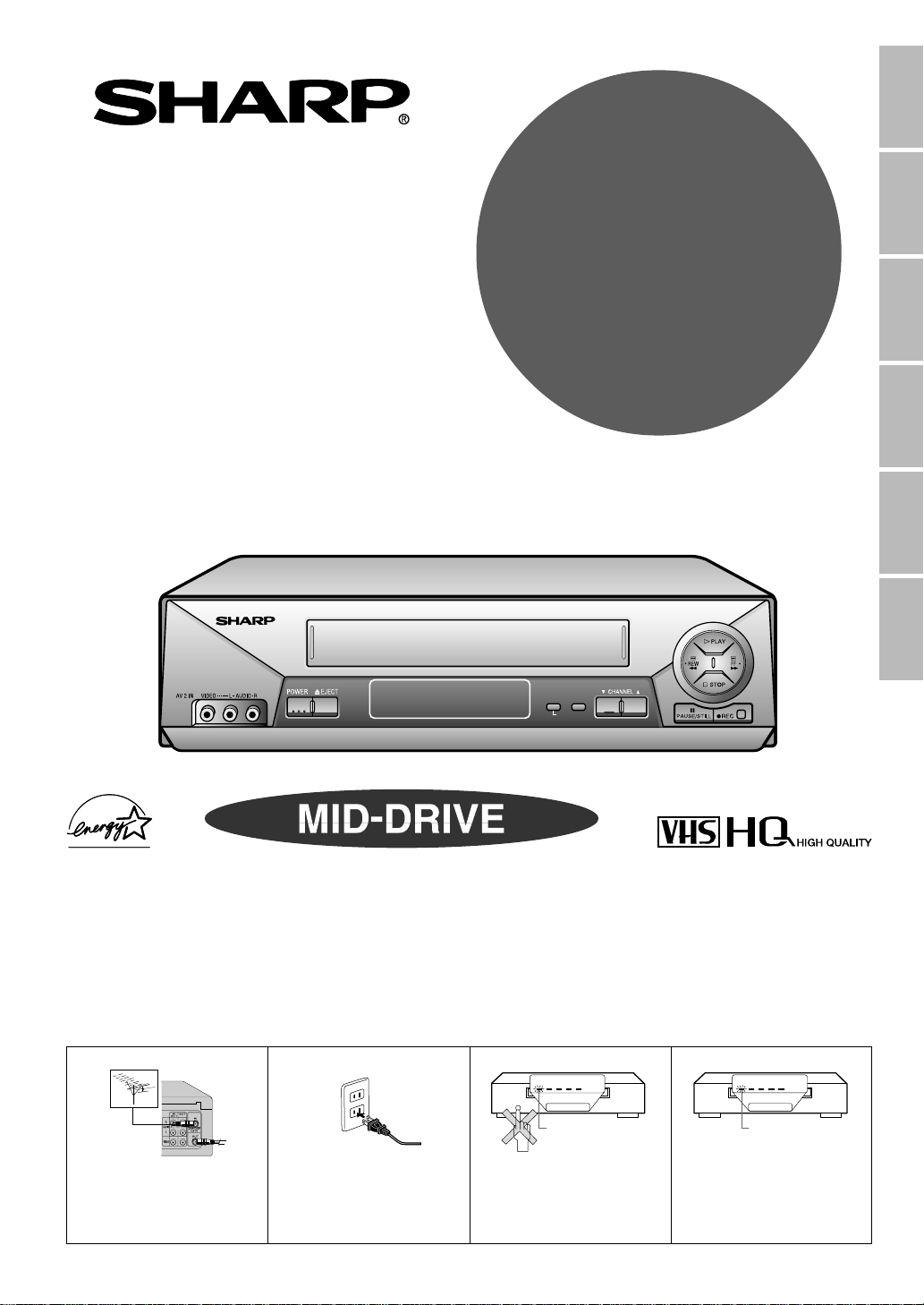
VIDEO CASSETTE RECORDER
OPERATION MANUAL
Please read this operation manual carefully
before using the VCR.
POWER VCR REC
TIMER
TAMPER
PROOF
REMOTE SENSOR
VC-A410U
VC-A411U
VC-A420U
VC-H810U
VC-H811U
VC-H820U
SET MENU
S.PICTURE
Setting Up
Operations
Basic
Recording
Functions
Special
Helpful
Hints
(VC-H820U)
[IMPORTANT]
EZ SET UP (AUTO CHANNEL/CLOCK SET UP)
! Connect Antenna/Cable
to VCR first.
@ Then, plug into AC
Power Outlet.
REMOTE SENSOR
TAMPER
TIMER
POWER VCR REC
PROOF
Flashing
# Do not press the POWER
button until completion of
EZ SET UP.
REMOTE SENSOR
TAMPER
POWER VCR REC
TIMER
PROOF
Flash slowly
$ EZ SET UP complete.
Detail: Please see page 15
1
Page 2
This video cassette recorder (VCR) uses “ONLY” cassette
tapes, NTSC video signals and 120 V AC, 60 Hz (standard
household
For future reference, record the model and serial number (located
on the rear of the VCR) in the space provided.
current).
Model No.:
Serial No.:
—————————
—————————
WARNING:TO REDUCE THE RISK OF FIRE OR ELECTRIC SHOCK, DO NOT
EXPOSE THIS APPLIANCE TO RAIN OR MOISTURE.
CAUTION: TO PREVENT ELECTRIC SHOCK, MATCH WIDE BLADE OF
PLUG TO WIDE SLOT, FULLY INSERT.
CAUTION: TO REDUCE THE RISK OF
ELECTRIC SHOCK, DO NOT
CAUTION
RISK OF ELECTRIC SHOCK
DO NOT OPEN
REMOVE COVER. NO USERSERVICEABLE PARTS INSIDE.
REFER SERVICING TO
QUALIFIED SERVICE
PERSONNEL.
This symbol warns the user of
uninsulated voltage within the
unit that can cause dangerous
electric shocks.
This symbol alerts the user that
there are important operating
and maintenance instructions in
the literature accompanying this
unit.
WARNING—Keep your VCR away from electrical and magnetic appliances which could impair performance.
Be sure to position your VCR away from your TV or video monitor by at least 8ⴖ.
WARNING OF DEW FORMATION
Whenever your VCR is moved from a cold to a warm environment, it is important that you plug the unit in, turn
the power on and allow it to sit for about 2 hours before attempting to play a tape. This period will allow any dew
formation to evaporate. Failure to do so may result in tape and/or video head damage.
After the 2 hour evaporation period, you may witness a “snowy” picture for the first few minutes of VCR
operation. This picture noise will disappear shortly thereafter.
As an ENERGY STAR
guidelines for energy efficiency. ENERGY STAR is a U.S. registered mark.
WHAT IS ENERGY STAR
TVs and VCRs use energy both when they are on and when they are off. North Americans spend more than $1
billion a year of energy consumed by TVs and VCRs when they are not in use. The new
models will reduce that energy “leakage” by up to 75 percent. Ultimately, this will mean more than $500 million a
year in energy savings for consumers.
The energy savings will help reduce the burning of fossil fuels and the related carbon dioxide pollution that
contributes to global warming. If every North American family replaced their TVs and VCRs with
®
STAR
eliminating the pollution from more than one million cars.
By using ENERGY STAR® products, you will save money on your electric bills and use less energy. This not
only makes good economic sense but also good for our environment.
models, it would reduce carbon dioxide emissions by five million tons every year -- equivalent to
®
Partner, SHARP has determined that this product meets the ENERGY STAR
®
ENERGY STAR
ENERGY
®
®
2
Page 3
IMPORTANT SAFEGUARDS AND PRECAUTIONS
CAUTION
READ THE SAFETY AND OPERATING INSTRUCTIONS before operating your VCR.
FOLLOW INSTRUCTIONS AND HEED ALL WARNINGS on your VCR and in this manual.
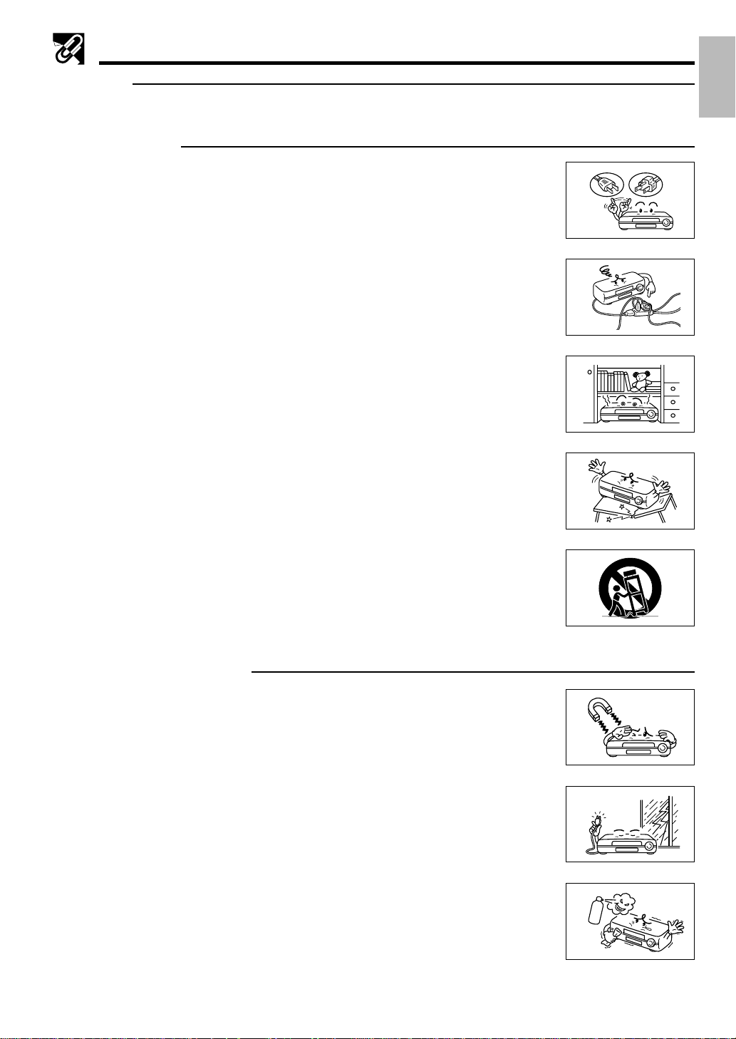
INSTALLATION
1. Operate only from a power source indicated on your VCR or in this manual. If you are
unsure of your power supply, ask your local power company.
2. As a safety feature, your VCR is equipped with either a 2-wire polarized plug (one
plug blade bigger than the other) or a 3-wire grounded plug (a third pin for
grounding). The 2-wire polarized plug will fit only one way into the power outlet. The
3-wire grounded plug will fit only into a grounding-type power outlet.
If the plug does not fit, ask your electrician to replace your obsolete outlet. Do not
modify the plug. To do so will void the safety feature.
3. Protect and route power cords so they will not be stepped on or pinched by anything
placed on or against them. Be especially careful at plug-ins, convenience receptacles
or cord exit points from the VCR. Frayed power cords or damaged plugs are
hazardous. Have them replaced by a qualified service technician.
Overloaded wall outlets and extension cords may cause fire or electrical shock
hazards.
4. Do not cover or block ventilation holes in the VCR cabinet. Doing so may damage the
VCR or cassette or cause fire.
Information
General
2
3
4
Do not place your VCR on a soft surface which could block ventilation holes on the
bottom. Avoid enclosed installations such as bookshelves or racks unless ventilation
is adequate.
5. Avoid excessive humidity, sudden temperature changes or temperature extremes.
Dew may form inside your VCR or on the cassette.
6. To avoid costly damage or injury, place your VCR flat on a solid, stable surface free
from vibrations; do not place any heavy objects on top of it. Use only a cart, stand,
tripod, bracket or table recommended by the manufacturer; follow all instructions
regarding their use exactly.
7. An appliance and cart combination should be moved with care. Quick stops,
excessive force and uneven surfaces may cause the appliance and cart combination
to overturn.
OPERATION/CLEANING
1. Keep your VCR away from electrical and magnetic appliances which could impair
performance. Be sure to position your VCR away from your TV or video monitor by at
least 8ⴖ.
2. Keep your VCR away from wet locations such as bathtubs, sinks, laundries, wet
basements and swimming pools.
3. Use only accessories recommended by the manufacturer to avoid fire, shock or other
hazards.
4. If your VCR has been exposed to rain, moisture or strong impact, unplug it and have
it inspected by a qualified service technician before resuming use.
5. Unplug your VCR and disconnect it from the antenna and/or cable system during a
lightning storm or an extended period of discontinued use.
6. Unplug your VCR before cleaning. Use a damp cloth for cleaning. Do not use
cleaning fluids or aerosols which could enter the unit and cause damage, fire or
electrical shock. These substances may also mar the finish of your VCR.
6
7
1
5
6
7. Never open or remove covers or make any adjustments not described in this manual.
Attempting to do so could expose you to dangerous electrical shock or other hazards.
It may also cause serious damage to your VCR.
3
Page 4
IMPORTANT SAFEGUARDS AND PRECAUTIONS
8. Keep liquids and foreign objects away from your VCR. Never operate your VCR if
any liquid or foreign object has entered it. Electrical shorts could result and possibly
8
cause fire or shock hazards. Unplug your VCR immediately and have it inspected by
a qualified service technician.
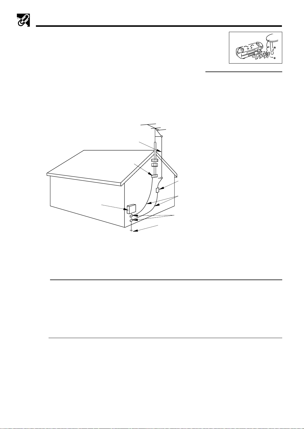
OUTDOOR ANTENNA GROUNDING AND POWER LINES
1. If an outside antenna or cable system is connected to your VCR, be sure the antenna or cable system is
grounded, thus providing some protection against voltage surges and built-up static charges. Section 810 of
the National Electrical Code, ANSI/NFPA No.70-1984, provides information regarding proper grounding of the
mast and supporting structure, grounding of the lead-in wire to an antenna discharge unit, size of grounding
conductors, location of antenna-discharge unit, connection to grounding electrodes and requirements for the
grounding electrode. See diagram below.
EXAMPLE OF ANTENNA
GROUNDING AS PER NATIONAL
ELECTRICAL CODE
ANTENNA LEAD-IN
WIRE
ELECTRIC
SERVICE
EQUIPMENT
NEC—NATIONAL ELECTRICAL CODE
GROUND CLAMP
POWER SERVICE GROUNDING
ELECTRODE SYSTEM
(NEC ART 250, PART H)
ANTENNA
DISCHARGE
UNIT
(NEC SECTION
810–20)
GROUNDING
CONDUCTORS
(NEC SECTION
810–21)
GROUND CLAMPS
2. An outside antenna system should not be located in the vicinity of overhead power lines or other electric light
or power circuits, or where it can come into contact with power lines or circuits. When installing an outside
antenna system, extreme care should be taken to keep from coming into contact with power lines or circuits;
contact with them might be fatal.
SERVICE
1. Do not attempt to service this VCR yourself. Instead, unplug it and contact a qualified service technician. (See
LIMITED WARRANTY at the end of this manual.)
2. Be sure the service technician uses authorized replacement parts or their equivalents. Unauthorized parts
may cause fire, electrical shock, or other hazards.
3. Following any service or repair, be sure the service technician performs safety checks to certify that your VCR
is in safe operating order.
OTHERS
1. For Your Information: Your full understanding of the following is appreciated. Parliament by statute has
decreed that it is illegal to make copies of copyrighted material of any manner or kind without the consent of
the copyright owner, subject to the “Fair Dealing” exceptions in the Act penalties may be imposed on those
guilty of making such copies.
2. Normally, your VCR does not require head cleaning. However, the heads may become clogged when an old
or damaged tape is used. If the playback picture becomes blurred, the heads may need cleaning. Head
cleaning should be performed by a qualified technician. Contact the nearest Sharp Factory Service Center or
Authorized Service Station. Do not use a cleaning tape unless it is new and of high quality. Excessive use of
cleaning tapes may also damage the heads.
4
Page 5
CONTENTS
General Information
IMPORTANT SAFEGUARDS AND
PRECAUTIONS................................................... 3
Features ................................................................. 6
Accessories ........................................................... 6
Major Components of Your VCR ......................... 7
Remote Control ..................................................... 8
• Inserting the Batteries
Setting Up
Connecting the VCR ............................................. 9
• RF Connection
• AV Connection
• After the Connection
• Setting the 3 ↔ 4 Output Channel Selector
Cable TV Connections .......................................... 10
Menu Screen.......................................................... 14
OSD (On Screen Display) ..................................... 14
• How to Display Indicators
EZ Set Up (With Auto Clock Setting)................... 15
Setting the Language............................................ 16
Setting the Clock................................................... 16
• Auto Clock Setting
• Manual Clock Setting
• Automatic Daylight Saving-Time (D.S.T.)
Adjustment
Setting the Channels ............................................ 19
• Adding Channel Memory/Erasing Channel
Memory
Mode Selection...................................................... 21
Recording
Recording a TV Program ...................................... 25
• Without a Cable Box or Digital Satellite
Receiver
• With a Cable Box or Digital Satellite Receiver
• To Watch Another TV Program While
Recording
• Cassette Erase Protection
• Recording Speeds
• Recording Hi-Fi Stereo Sound
• Recording MTS (Multi-channel TV Sound)
Broadcasts
• Monitor Output When Receiving a SAP
Broadcast
• Tape Dubbing Connection Instructions
Simple Recording Timer....................................... 28
• Changing the Contents of the Simple
Recording Timer
• Cancelling the Simple Recording Timer
Recording with the Timer ..................................... 29
• Confirming Timer Programs
• Cancelling Timer Programs
Special Functions
Sharp Super Picture.............................................. 32
Recorded Section Auto Repeat ........................... 32
Auto Zero Back...................................................... 32
DPSS (Digital Program Search System) ............. 33
Skip Search............................................................ 33
Instant Replay........................................................ 33
Tamper Proof......................................................... 34
Basic Operations
Playback................................................................. 22
• Inserting a Video Cassette
• Playback
• Fast Forward and Rewind
• Video Search
• Slow Motion Playback (only with the remote
control)
• Still Picture and Frame Advance
• Automatic Tracking Control System
• Manual Tracking Control
• Blue Screen Noise Elimination
• Quick Start with Full Loading Mechanism
• Full Automatic Playback
• Audio Output Mode
Helpful Hints
Specifications........................................................ 35
Troubleshooting.................................................... 36
Service Information............................................... 36
LIMITED WARRANTY............................................ 38
5
Page 6
Features
Only for VC-H810U, VC-H811U, VC-H820U
• Hi-Fi Stereo Sound
• Built-in MTS (Multi-channel TV Sound) Decoder
— Lets you record stereo or SAP (Separate Audio
Program) broadcasts.
Common Features
• EZ Set Up — VCR tuner channels and clock are
automatically set for both Air and Cable channels.
• S-VHS Quasi Playback
Notes for S-VHS tape
• Playback of S-VHS recorded tapes is possible.
• Playback of S-VHS image quality is not available.
• Picture noise or distortion may appear on the screen
during playback in the SLOW or STILL mode.
• S-VHS recording is not available. However, HQ recording
is possible with S-VHS tape.
• Double-Azimuth 4-Heads
µ
Clear Picture System (in EP mode) — For
•19
enhanced picture quality in EP (Extended Play)
mode.
System for Better Resolution and Color Re-
•
production
• Multi-Language (English/Spanish/French) OSD
(On Screen Display) with Menu Screen Guidance
— On-screen setting and recording instructions.
• 181-channel PLL Quartz Synthesized Random
Access Tuner with Automatic Channel Setting
• Quick Start with Full Loading Mechanism
• 1-Year, 8-Event Programmable Timer
• Simple Recording Timer
• Unified Remote Control
• Sharp Super Picture — Enhances picture quality
during playback.
• 5 Seconds Timer Backup
• Field-Still/Variable Slow/Frame Advance
• Automatic Daylight Saving-Time (D.S.T.)
Adjustment — Automatically adjusts VCR clock to
daylight saving-time.
• Blue Screen Noise Elimination
• Auto Tracking Control System — Automatically
adjusts tracking during playback.
• Digital Program Search System (DPSS) — Quickly
locates the beginning of a specific recording.
• Skip Search — Quickly operates a forward video
search in 30 second intervals, then resumes
playback.
• Instant Replay — Quickly operates a reverse video
search in 20 second intervals, then resumes
playback.
• Auto Zero Back — Quickly finds “0:00.00” point
and stops there.
• Recorded Section Auto Repeat — Continually
plays back a recorded section of the tape.
• Full Automatic Playback
• Tamper Proof — Prevents accidental change of the
operation mode.
• Up to 8 Hours of Recording and Playback (with
T-160 cassette)
Only for VC-A420U, VC-H820U
• Built-in Front AV Jacks — For easy connection of
audio/video equipment such as the Sharp Viewcam.
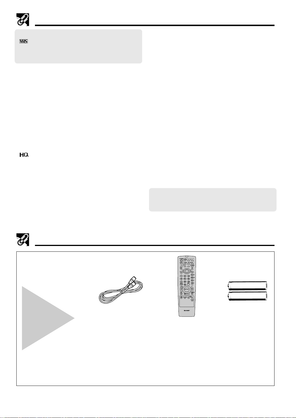
Accessories
Be sure that the
following
accessories are
all included with
your VCR.
Round coaxial cable
(75 Ohm, 1 m [3-1/4 ft.])
QCNW-8115AJZZ
or
(75 Ohm, 0.9 m [3-11/18 ft.])
QCNW-8530AJZZ
or
QCNW-8533GEZZ
or
QCNW-8555AJZZ
or
QCNW-8614AJZZ
VIDEO CASSETTE RECORDER
Remote control unit
RRMCG1236AJSA
or
RRMCG1236AJSB
or
RRMCG1236AJSC
AA batteries for
the remote
control unit
6
Page 7
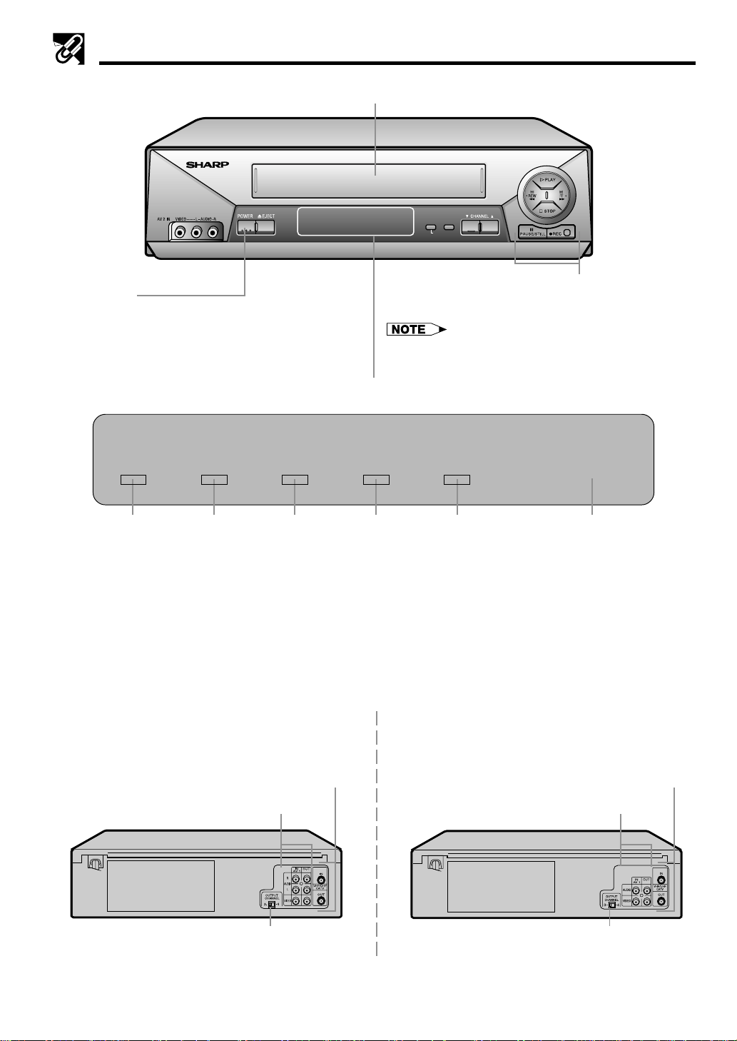
Major Components of Your VCR
[Front]
(VC-H820U)
POWER button
(When pressed to turn on the VCR, POWER LED indicator
will light up. When the power is turned off, POWER LED
indicator will turn off.)
Cassette compartment (see Playback/Recording)
TIMER
POWER VCR REC
LED Indicator (explained throughout the operation instruction)
POWER TIMER VCR REC PROOF
REMOTE SENSOR
TAMPER
PROOF
SET MENU
S.PICTURE
Basic function controls
(see Playback/Recording)
• The design may be slightly different depending on the
model.
TAMPER
REMOTE SENSOR
!@#$% ^
! POWER LED indicator
This indicator lights up whenever the VCR is turned on.
@ TIMER LED indicator
This indicator lights up when the VCR is set for timer
recording, Simple Recording Timer and Recording with
the Timer.
# VCR LED indicator
This indicator lights up when selecting “VCR” by using
the TV/VCR button.
[Rear]
(VC-H810U, VC-H811U, VC-H820U)
Connection terminals (see Connecting the VCR and
Cable TV Connections)
Connection terminals (see Tape Dubbing)
3 ↔ 4 OUTPUT CHANNEL selector
(see Setting the 3 ↔ 4 Output Channel Selector)
$ REC LED indicator
This indicator lights up during recording. This indicator
flashes during REC-Pause.
% TAMPER PROOF (ÿ) LED indicator
This indicator lights up when the set mode is locked.
^ Remote Sensor
Point Remote Control at this window.
(VC-A410U, VC-A411U, VC-A420U)
Connection terminals (see Connecting the VCR and
Cable TV Connections)
Connection terminals (see Tape Dubbing)
3 ↔ 4 OUTPUT CHANNEL selector
(see Setting the 3 ↔ 4 Output Channel Selector)
7
Page 8
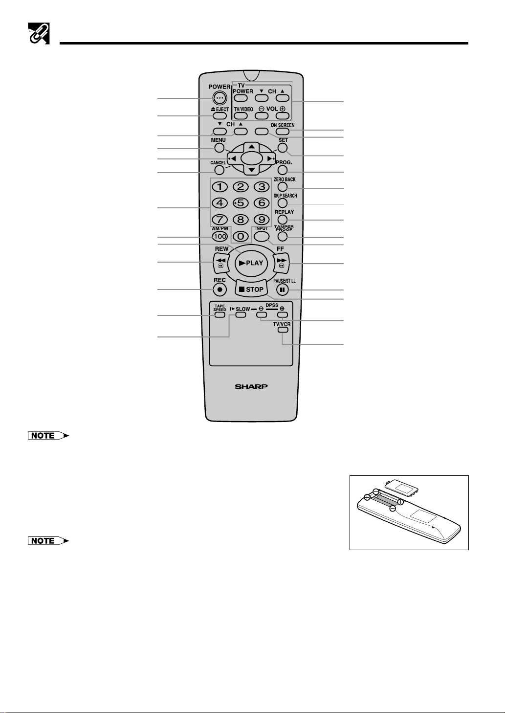
Remote Control
POWER button (p. 16)
EJECT button (p. 22)
CH (CHANNEL) ∂/ƒ buttons (p. 28)
MENU button (p. 14)
∂/ƒ/ß/© button (p. 16)
CANCEL button (p. 31)
TV Functions Control buttons
(POWER, CH ∂/ƒ, VOL j/k and
TV/VIDEO)
• This Remote Control can control many
of SHARP’s TVs.
ON SCREEN button (p. 14)
(*)
SET button (p. 16)
PROG. (PROGRAM) button (p. 29)
ZERO BACK button (p. 32)
Numbered buttons (p. 18)
100/AM/PM button (p. 18)
PLAY button (p. 22)
REW button (p. 23)
REC button (p. 25)
TAPE SPEED button (p. 25)
SLOW button (p. 23)
VIDEO CASSETTE RECORDER
*: This button cannot be used for this model.
Inserting the Batteries
Make sure that the batteries have been properly installed first. Fit two batteries
type “AA”. If the remote control stops working, fit new batteries.
Ensure the batteries are fitted correctly, matching the polarities (j/k) indicated
in the remote control.
SKIP SEARCH button (p. 33)
REPLAY button (p. 33)
TAMPER PROOF button (p. 34)
INPUT button (p. 27)
FF button (p. 23)
PAUSE/STILL button (p. 23)
STOP button (p. 22)
j/k buttons (SLOW j/k,
DPSS j/k) (p. 33)
TV/VCR buttons (p. 16)
• Do not subject the remote control to shock, water or excessive humidity.
• The remote control may not function if the VCR sensor is in direct sunlight or any other
strong light.
• Incorrect use of batteries may cause them to leak or burst. Read the battery warnings and use the batteries properly.
• Do not mix old and new batteries, or mix brands in use.
• Remove the batteries if the remote control will not be operated for an extended period of time.
• If the remote control does not function properly when new batteries are installed, remove the batteries and keep pressing
any button for 10 seconds before re-installing them.
8
Page 9
Connecting the VCR
The connection method differs depending on the type of TV.
If you have cable TV (CATV), see Cable TV Connections.
RF Connection (for connection to a TV without AV terminals)
! Disconnect the TV antenna from the TV.
@ Connect the TV antenna cable to the ANTENNA IN terminal on the rear of the VCR.
# Connect the TV OUT terminal on the rear of the VCR with the antenna terminal on the TV using a coaxial
cable. Select the TV channel 3 or 4 corresponding to the 3 ↔ 4 output channel selector of the VCR. (See
Setting the 3 ↔ 4 Output Channel Selector below.)
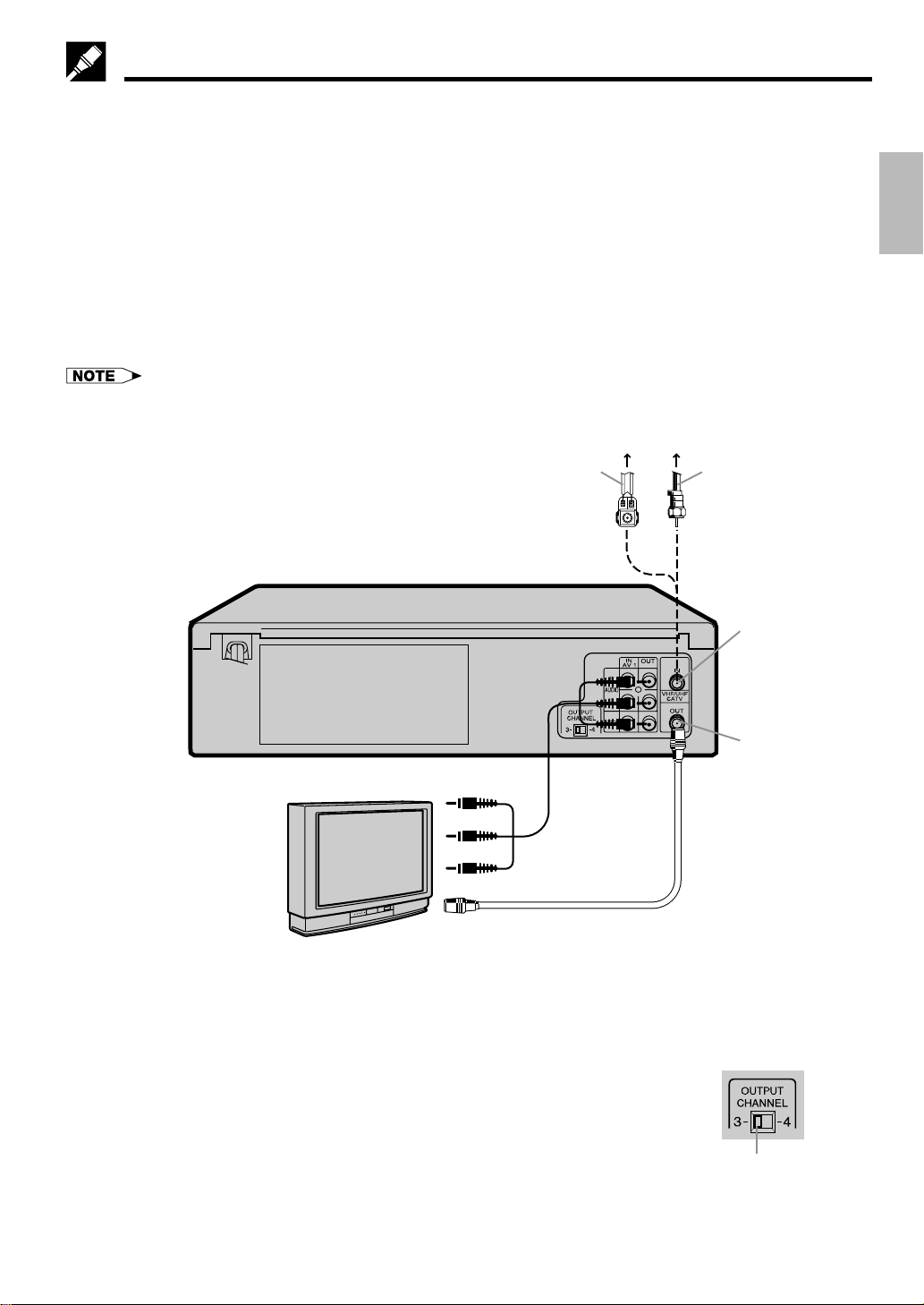
AV Connection (for connection to a TV with AV terminals)
! Disconnect the TV antenna from the TV.
@ Connect the antenna, VCR, and TV using the Audio/Video cable and coaxial cable (supplied) as shown.
# Select the video input mode or A/V input mode on your TV. (See the TV operation manual for details.)
• If your VCR is a monaural model, connect the audio cable to “AUDIO OUT” on the VCR.
Antenna
Connect the flat twin lead cable
to a transformer
(300 ohm to 75 ohm, not
supplied)
VCR Rear
(Hi-Fi model)
Coaxial cable
ANTENNA IN
(antenna or
cable input)
Setting Up
Audio/Video
cable (not
supplied)
TV
Coaxial cable (supplied)
After the Connection
Plug in the power cord of the TV. Then go to EZ Set Up.
Setting the 3 ↔ 4 Output Channel Selector
The 3 ↔ 4 OUTPUT CHANNEL selector changes the VCR OUTPUT to standard
TV broadcasting signals. Both your TV and VCR must be set to the same
channel (i.e. TV on channel 3 and VCR OUTPUT CHANNEL selector on 3).
Your VCR is set to channel 3 at the factory, so your TV should be tuned to
channel 3 as well. If channel 3 is an active broadcast channel in your area, set
the VCR 3 ↔ 4 OUTPUT CHANNEL selector to 4 and tune your TV to channel 4.
TV OUT
Rear of Your VCR
3 ↔ 4 OUTPUT CHANNEL
selector
9
Page 10
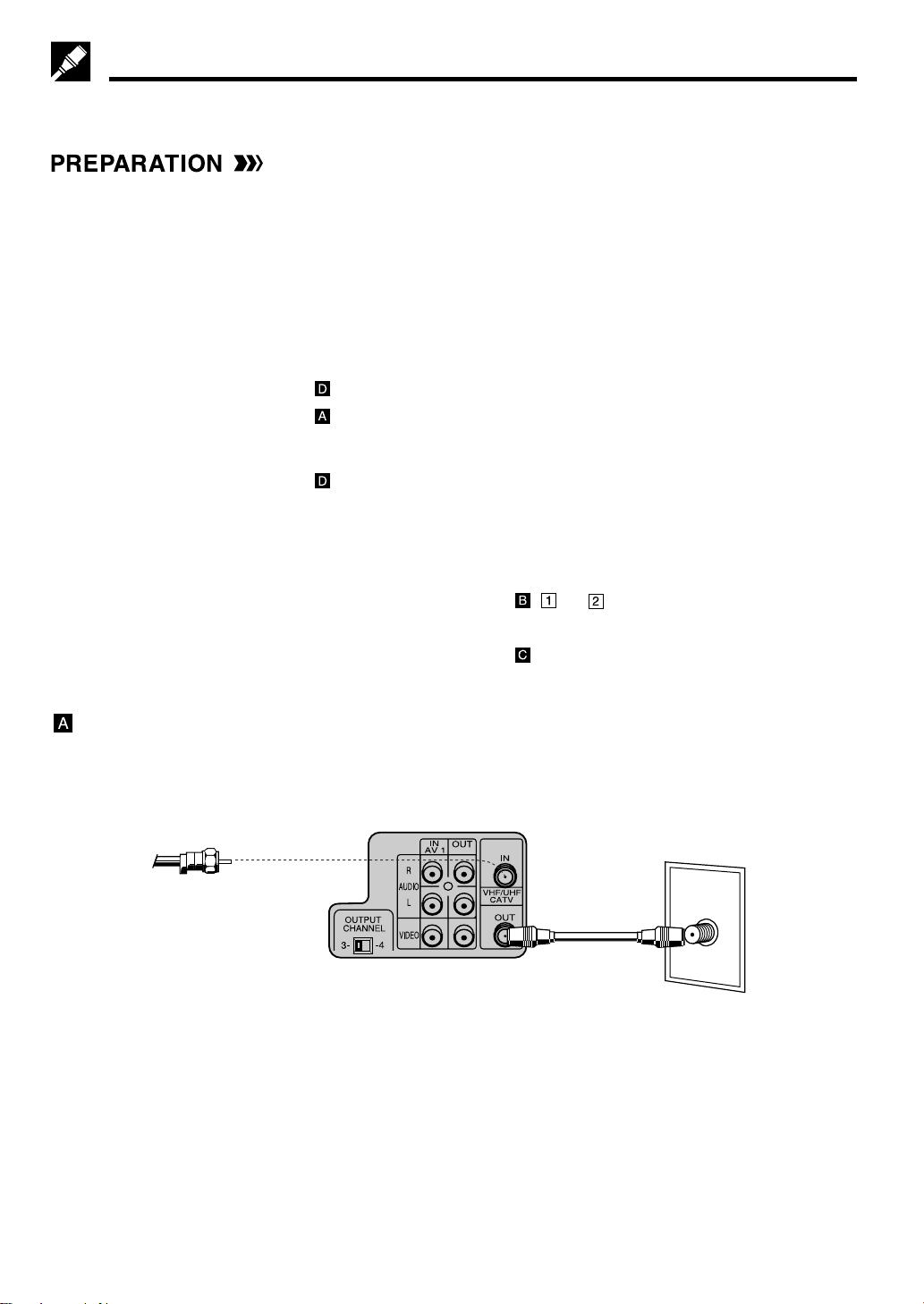
Cable TV Connections
Your VCR is capable of receiving the following non-scrambled channels.
• Scrambled channels can be received with the cable box supplied by your cable TV company.
Set the 3 ↔ 4 OUTPUT CHANNEL selector on the rear of the VCR to 3 or 4. (Factory preset: 3)
First check your TV/CATV system
Step Q Is your TV cable compatible with the VCR?
•YES → Go to Step W
•NO → Go to Step E
Step W Does your CATV system have some or all channels scrambled?
•YES → Go to
•NO → Go to
Step E Does your CATV system have some or all channels scrambled?
•YES → Go to
•NO → Go to Step R
Step R Choose the type below.
•Basic connection (only for
descrambled CATV signals.) → Go to - or
•To watch a CATV program while recording a TV program
by using the A/B switch. → Go to
Connection without a cable box
• Connect as shown. Then go to “After the Connection”.
VCR Rear (Hi-Fi model)
From CATV system
Coaxial
cable
(Supplied)
TV Rear
ANT/CABLE
10
Page 11
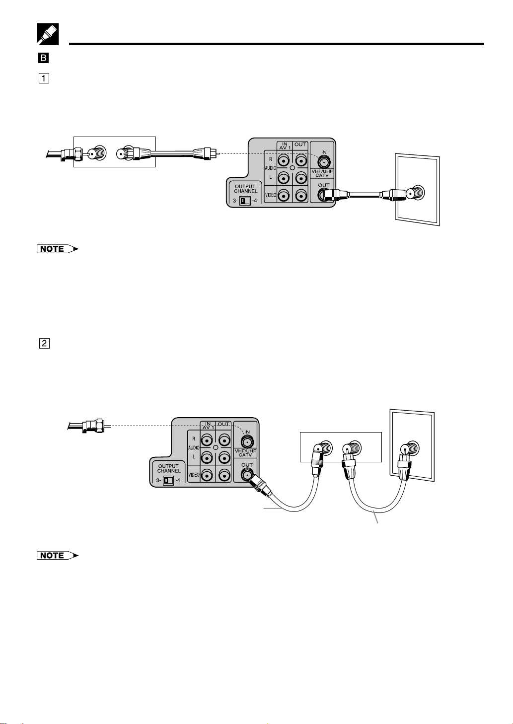
Cable TV Connections
Connection with cable box
• Connect as shown. With this connection, it is possible to record descrambled CATV signals. Then go to “After
the Connection”.
VCR Rear (Hi-Fi model)
TV Rear
ANT/CABLE
From
CATV
Cable Box
OUTIN
Coaxial cable
(Not supplied)
system
Coaxial
cable
(Supplied)
• If the cable box is turned off, it will not output any signals, thus making it impossible to record or view a program from the
CATV system.
• In the case of the above connections, it is not possible to change channels using the VCR remote control. Only the cable
box can be used to change channels.
• Only one channel at a time can be programmed for recording programs with the timer. It is not possible to watch a TV
program different from the one being recorded.
• Depending on which terminals the TV has, a separate combiner (mixer) or separator (splitter) may be necessary.
•Connect as shown. With this connection, it is not possible to record CATV programs which have been
scrambled, but is possible to record one channel and watch the other one. Then go to “After the
Connection”.
From CATV system
VCR Rear (Hi-Fi model)
Cable Box
OUTIN
TV Rear
ANT/CABLE
Coaxial cable
(Supplied)
• With the above connection, ∂/ƒ of the VCR or the numbered buttons on the remote control can be used to select channels.
• Depending on which terminals the TV has, a combiner (mixer) or separator (splitter) may be necessary.
• To record one channel and watch another, the VCR must be set to the TV mode.
Coaxial cable
(Not supplied)
11
Page 12
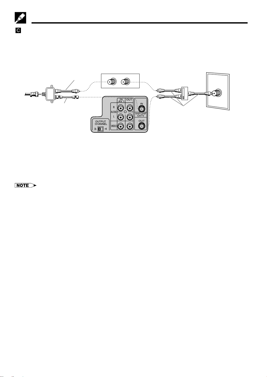
Cable TV Connections
Connection with cable box, A/B switch and splitter
By using an A/B switch or splitter, it is possible to switch between the cable box and the VCR output.
For example, while recording a TV program with the VCR, it is possible to watch a CATV program (including
descrambled programs) using the A/B switch.
• Connect as shown. Then go to “After the Connection”.
Cable Box
OUTIN
From
CATV
system
Splitter
(Not supplied)
Coaxial cable
(Supplied)
Coaxial cable
(Not supplied)
VCR Rear (Hi-Fi model)
Using the A/B Switch
1. Set the A/B switch to the “A” position in the following situations.
! To watch a cable TV program while recording another program.
@ To watch a scrambled cable TV program.
# To watch a cable TV program when the VCR is turned off.
• Use the cable box to change channels.
• If you turn off the cable box, you cannot watch a CATV program.
2. Set the A/B switch to the “B” position in the following situations.
! To play back a cassette on the VCR.
@ To watch a program which is being recorded with the VCR tuner.
# To watch a program using the VCR tuner.
A/B switch
(Not supplied)
A
B
Coaxial cable
(Not supplied)
TV Rear
ANT/CABLE
12
Page 13

Cable TV Connections
Connection with two cable boxes, A/B switch and splitter
The following connection is necessary to record a cable TV program (even those scrambled by a cable
company) while watching another cable TV program. The following connection requires two cable boxes, a 2way splitter and an A/B switch.
• Connect as shown. Then go to “After the Connection”.
From
CATV
system
Splitter
(Not supplied)
Coaxial cable
(Not supplied)
Cable Box 1
OUTIN
VCR Rear (Hi-Fi model)
A/B switch
(Not supplied)
A
B
Coaxial cable
(Not supplied)
TV Rear
ANT/CABLE
Cable Box 2
OUTIN
Coaxial cable
(Supplied)
Using the A/B Switch
1. Set the A/B switch to the “A” position in the following situations.
! To watch a cable TV program while recording another program.
@ To watch a cable TV program when the VCR is turned off.
2. Set the A/B switch to the “B” position in the following situations.
! To play back a cassette on the VCR.
@ To watch a program being recorded, or to change (or watch) channels with the cable box 2. The output
channel of the cable box 2 and the VCR must be the same.
• If you turn off the cable box, you cannot record or view a CATV program.
• If you have questions regarding any connection procedure, please contact your cable company or the nearest Sharp
Authorized Service.
After the Connection
Plug in the power cords of the TV and cable box.
Then go to EZ Set Up.
13
Page 14

Menu Screen
MENU screen is a home screen used to select various screen functions. A submenu will appear once you select an item for the menu.
! Turn on the TV and select the video channel. (See Setting the 3 ↔ 4
Output Channel Selector on page 9.)
@ Press POWER (POWER LED indicator will light up) and then TV/VCR to
select “VCR” (VCR LED indicator will light up).
# Press MENU to display the MENU screen.
MENU
TIMER
SET UP
CHANNEL PRESET
CLOCK
LANGUAGE
SELECT :
ENTER :SET EXIT :MENU
The following 5 items can be set by using the MENU screen.
TIMER............................... Setting a timer recording (and checking it). (See page 29.)
SET UP ............................. VCR operating conditions are set according to the broadcast reception and tape
playback conditions. (See page 21.)
CHANNEL PRESET .......... Setting the channels. (See page 19.)
CLOCK ............................. Setting the present time. (See pages 16–18.)
LANGUAGE ..................... Selection of language to be used for the MENU screen. (See page 16.)
$ Press ∂/ƒ and then SET. The screen changes to the one which you have selected.
% To cancel the MENU screen, press MENU.
OSD (On Screen Display)
To facilitate the operation and check the current VCR mode information, the following OSD (On Screen Display)
will appear on the TV screen when using this VCR.
Display example
STOP 123
S. PICTURE ON STEREO
SP STOP 11:30AM SAPSAP
L R
FRI 4/25 DPSS 19
10:00AM 1:59.19
Program channel position
Stereo/SAP mode
Audio Output mode
DPSS
Real time counter
PLAY
FF
REW
STOP
REC
PAUSE
Play
Recorded Section
- - - - - - - Function status
Fast
forward
Rewind
Stop
Rec
Rec
pause
Sharp Super Picture
Simple Recording Timer
Calendar display
Auto Repeat
Tape speed
Clock display
• If the clock is not set, the time and date will not be displayed.
• Stereo/SAP and Audio Output modes are only for Hi-Fi models.
How to Display Indicators
Each time ON SCREEN is pressed, the screen changes as follows:
! AUTO Display @ FULL Display # COUNTER Display $ Display off
AUTO Display
When an operation button, numbered button or CH ∂/ƒ is pressed, the current function status or the number
of the channel will be displayed in the upper section of the TV screen for about 3 seconds.
PLAY
(When you press
PLAY)
REC 09
• When the VCR power is turned off, the display mode is retained in memory.
• When you record a video signal output from this VCR on another VCR, press ON SCREEN to select Display Off. (If the
function status is displayed on the screen, it is also recorded on the tape.)
14
(When you press
REC while you are
receiving CH 9.)
Page 15

EZ Set Up (With Auto Clock Setting)
IMPORTANT (Caution during EZ Set Up):
• Do not press the POWER button on the
VCR or remote control.
• Do not insert a video cassette into the VCR.
The EZ Set Up function automatically sets the tuner channels and clock when the antenna cable is connected to
the rear of the VCR and the power plug is then connected to an AC outlet.
IMPORTANT:
When using a cable box:
• See Cable TV Connections.
• Leave POWER on the cable box turned on and select a channel that carries EDS signals.
During Auto Channel Setting and
Auto Clock Setting
TIMER
POWER VCR REC
Flashes quickly
佣
TAMPER
PROOF
REMOTE SENSOR
! Make sure that the antenna cable is connected. For
connection configuration, refer to Connecting the
VCR.
@ Connect the VCR power plug to an AC outlet.
# The tuner channels and clock will automatically be
set. The POWER LED indicator will flash quickly to
indicate the setting.
EZ Set Up complete
TIMER
POWER VCR REC
TAMPER
PROOF
REMOTE SENSOR
• This VCR can monitor and use time-signals (EDS
signals), which are provided by some TV stations, to
automatically adjust the VCR clock. This VCR
automatically searches EDS signals, but if you are in
a hurry to use timer recording or know the channel
Flash slowly
of the EDS signal carrier in your area, follow the
procedure in Auto Clock Setting or Manual Clock
Setting.
$ When the setting is completed, POWER LED indicator
will flash slowly.
• If power is supplied to the VCR before the cable is connected, EZ Set Up will not be able to preset the channels into
memory. If this occurs unplug the VCR from the power source and wait a few minutes. Check the cable/antenna connection
and supply power to the VCR. EZ Set Up will automatically begin again.
• If the power is turned on during EZ Set Up, the Auto Channel setting will be interrupted and the tuner channels will not be
able to be preset.
• Auto Clock Setting may take several minutes.
• If the Auto Clock Setting is not completed within 30 minutes, there may be no channels with EDS signals. In this case, set the
clock manually. (See Manual Clock Setting.)
• If the antenna signal is weak, the Auto Clock Setting function may not operate.
• During initial channel setting, the channels are set into the AIR channel setting. To watch a cable TV channel, select “CATV”
on the CHANNEL PRESET screen. (See Setting the Channels.)
15
Page 16

Setting the Language
When you use the VCR for the first time or the power is
interrupted for more than 5 seconds (power failure, etc.),
you should set the language to be used for the MENU
screen.
∂
MENU
ß
(Remote Control)
SET
©
• Turn on your TV and select the video channel.
(See Setting the 3 ↔ 4 Output Channel Selector.)
• Press POWER (POWER LED indicator will light up) and
ƒ
then TV/VCR to select “VCR”. (VCR LED indicator will
light up.)
LANGUAGE
ENGLISH
ESPANOL
FRANÇAIS
佡
SELECT :
ENTER :SET EXIT :MENU
佡
• If you press MENU to exit the LANGUAGE screen in Step #, the data will not be stored.
• You can also use the ∂ (CHANNEL ∂), ƒ (CHANNEL ƒ), © (FF è), ß (REW È), MENU or SET buttons on the VCR to
set the On Screen Display (OSD).
佡
∂
ƒ
Normal
Screen
! Press MENU.
LANGUAGE screen will appear.
@ Select the language with ∂/ƒ.
Ex.: ENGLISH
# Press SET to enter. To return to the normal screen, press
the MENU button.
Setting the Clock
Auto Clock Setting (If you DO know a channel that carries EDS signals)
• Make sure that the antenna cable is connected and connect the power cord.
• Turn on your TV and select the video channel. (See Setting the 3 ↔ 4 Output Channel Selector.)
• Press POWER (POWER LED indicator will light up) and then TV/VCR to select “VCR”. (VCR LED indicator will
light up.)
IMPORTANT:
When using a cable box:
• See Cable TV Connections.
• Leave POWER on the cable box turned on and select a channel that carries EDS signals.
! Press MENU.
Select “CLOCK” with ∂/ƒ and then press SET.
@ Select “AUTO” with ∂/ƒ and then press SET.
∂
佡
ƒ
CLOCK
∂
AUTO
ƒ
MANUAL
MENU
TIMER
SET UP
CHANNEL PRESET
CLOCK
LANGUAGE
SELECT :
ENTER :SET EXIT :MENU
佡
佡
16
EDS CH SET AUTO MANUAL
ß
EDS CH 02
©
AL
# Set EDS CH SET mode to “MANUAL” with ß/©
ƒ
佡
and then press ƒ.
Page 17

Setting the Clock
$ Select a channel that carries EDS signals with ß/©.
EDS CH SET AUTO MANUAL
EDS CH 07
佡佡
• If the EDS CH SET mode is set to MANUAL mode in Step # and a channel that does not carry EDS signal is selected in
Step $, the Auto Clock Setting function will not operate.
• In Step $, the number of channels that can be selected depends on the mode setting on the CHANNEL PRESET screen.
See the table below.
AIR/CATV Channels to be selected
AIR
CATV
• In Step !, if you press MENU when operating the screen setting for the first time or after a power failure of more than 5
seconds, the LANGUAGE screen will appear.
• If you entered incorrect data during the setting procedure, re-enter the correct data in the following manner:
1 Use ß /© to select the data to be corrected.
2 Set the correct data with ∂/ƒ.
3 After correcting the data in Step 2, press SET to enter.
• If you press MENU in Step %, the data will not be stored.
• If a button is not pressed within 3 minutes during the setting procedure, the screen will return to the normal screen.
Normal
Screen
02 03 04 68 69 02
01 02 03 124 125 01
ß
©
Ex.: 07
• The number of channels that can be selected depends
on the mode setting on the CHANNEL PRESET screen.
See NOTE.
When using a cable box:
Input the output channel (02, 03 or 04) of the cable box.
% Press SET to enter. The screen returns to normal.
Press POWER to turn off the VCR (VCR LED indicator will
turn off and POWER LED indicator will turn off).
The Auto Clock Setting function will automatically set the
clock.
Manual Clock Setting
• Turn on your TV and select the video channel. (See Setting the 3 ↔ 4 Output Channel Selector.)
• Press POWER (POWER LED indicator will light up) and then TV/VCR to select “VCR”. (VCR LED indicator will
light up.)
MENU
TIMER
SET UP
∂
CHANNEL PRESET
佡
CLOCK
LANGUAGE
ƒ
SELECT :
ENTER :SET EXIT :MENU
CLOCK
AUTO
MANUAL
∂
ƒ
SELECT :
ENTER :SET EXIT :MENU
佡
佡
! Press MENU.
Select “CLOCK” with ∂/ƒ and then press SET.
@ Select “MANUAL” with ∂/ƒ and then press SET.
17
Page 18

CLOCK
TIME DATE YEAR DST
10:28AM
7/04WED 01 ON
SELECT : CHANGE:
ENTER :SET EXIT :MENU
ß /©
and
∂/ƒ
Setting the Clock
# Select “TIME” with ß/© and set time by holding ∂/ƒ.
Ex.: 10:28 AM
Numbered buttons can be used instead of ∂/ƒ to set
time and date. Press AM/PM (100) to select AM or PM
during time setting.
$ Select and set “DATE”, “YEAR” and “DST” in turn, in the
same manner as in Step #.
• See Automatic Daylight Saving-Time (D.S.T.) Adjust-
ment.
Ex.: Jul. 4, 2001, DST: ON
Normal
佡
Screen
% If the data is correct, press SET to enter.
The screen returns to normal.
• In Step !, if you press MENU when operating the screen setting for the first time or after the power is interrupted for more
than 5 seconds, the LANGUAGE screen will appear.
• If you entered incorrect data during the setting procedure, re-enter the correct data in the following manner:
1 Use ß /© to select the data to be corrected.
2 Set the correct data with ∂ /ƒ.
3 After correcting the data in Step 2, press SET to enter.
• If you press MENU to exit the CLOCK screen in Step %, the data will not be stored.
• If a button is not pressed within 3 minutes during the setting procedure, the screen will return to the normal screen.
Automatic Daylight Saving-Time (D.S.T.) Adjustment
This VCR is equipped with an internal Automatic Daylight Saving-Time Adjustment function. In spring (first
Sunday in April) and autumn (last Sunday in October), the time is adjusted as shown below. This function has
been preset to ON at the factory. Set the D.S.T. mode in the clock setting screen.
Spring
Programmed timer recording set within this time frame (2:00
AM to 3:00 AM) will not be carried out.
First Sunday in April (D.S.T. is ON)
1:00 AM 2:00 AM
䢇
䢇
The clock is automatically
advanced 1 hour.
䢇䢇
3:00 AM
4:00 AM
Autumn
Because there will be two time frames from 1:00 AM to 2:00
AM, timer programming set between these times will be
influenced by the time change.
Last Sunday in October (D.S.T. is ON)
2:00 AM1:00 AM
䢇
The clock is automatically
set back 1 hour.
1:00 AM
䢇
䢇䢇
2:00 AM
• If the timer recording program is affected by the D.S.T. time change, check your TV listing and find out when it reflects the
time change. Some TV listings will indicate the time change in the same manner as is programmed in this VCR, but others
do not show the time change until the next morning. In that case, when programming a timer, use the CLOCK screen to set
the D.S.T. mode to OFF so the time change will not be carried out.
18
Page 19

Setting the Channels
Your VCR can receive a maximum of 181 channels as shown below by presetting the channels into memory.
(VHF: 2 to 13, UHF: 14 to 69, CATV: 1 to 125)
• Make sure that the cable (antenna or CATV) is connected to the IN terminal on the rear of the VCR.
MENU
TIMER
SET UP
∂
CHANNEL PRESET
CLOCK
佡
LANGUAGE
ƒ
SELECT :
ENTER :SET EXIT :MENU
CHANNEL PRESET
ß
AIR/CATV AIR CATV
CHANNEL PRESET
©
CH SET AUTO MANUAL
AIR/CATV AIR CATV
ß
CH SET AUTO MANUAL
©
02
AUTOMATIC TUNING.
PLEASE WAIT.
• Automatic tuning will not start unless the arrow is at “CH SET-AUTO” position.
• If a button is not pressed within 3 minutes during the setting procedure, the screen will return to normal.
• If the power is interrupted for more than 5 seconds, AIR/CATV selection must be set again.
• Automatic tuning will be interrupted if PLAY, REC or MENU buttons are pressed before the screen returns to normal.
佡
佡
佡
佡
Normal
Screen
! Press MENU.
Select “CHANNEL PRESET” with ∂/ ƒ and then press
SET.
@ Select “AIR” or “CATV” with ß/© and then press ƒ.
Ex.: AIR
ƒ
• To watch cable TV after EZ Set Up, select “CATV”,
press SET.
# Set “CH SET” to “AUTO” with ß/© and then press SET.
$ The auto tuning will start.
The channel display will count up and when finished, the
screen returns to normal.
19
Page 20

Setting the Channels
Adding Channel Memory/Erasing Channel Memory
Use this function to manually add or erase channels to/from the memory.
! Select the channel to be added with the numbered buttons and the channel to be erased with
the CH ∂/ƒ or numbered buttons.
MENU
TIMER
SET UP
∂
CHANNEL PRESET
CLOCK
佡
LANGUAGE
ƒ
SELECT :
ENTER :SET EXIT :MENU
CHANNEL PRESET
∂
AIR/CATV AIR CATV
ƒ
CH SET AUTO MANUAL
[ADD]
ADD 03
CHANNEL SELECT :
ADD/ERASE :
EXIT :MENU
ß / ©
[ERASE]
ß
©
@ Press MENU. Select “CHANNEL PRESET” with ∂/ ƒ and
press SET.
佡
# Select “CH SET” with ∂/ƒ and then select “MANUAL”
with ß/©. Then press SET.
佡
$ Select “ADD” if you want to add the channel memory or
“ERASE” if you want to erase the channel memory with
ß /©.
ERASE 03
Normal
佡
Screen
• If the power is interrupted for more than 5 seconds, the channel memory may be erased. If this happens, reset the channels
again and reset AIR/CATV selection.
• If a button is not pressed within 3 minutes during the setting procedure, the screen will return to normal.
% Press MENU to return to the normal screen.
20
Page 21

Mode Selection
MODE SELECTION
You can use the SET UP–selection screen to select the mode for basic features.
• Turn on the TV and select the video channel. Press POWER (POWER LED indicator will light up) and then
TV/VCR to select “VCR” (VCR LED indicator will light up).
MENU
TIMER
SET UP
∂
CHANNEL PRESET
佡
CLOCK
LANGUAGE
ƒ
SELECT :
ENTER :SET EXIT :MENU
[AUTO REPEAT]
AUTO REPEAT ON OFF
BLUE SCREEN ON OFF
SAP ON OFF
AUDIO OUTPUT
ß
MONO LR L R
©
SELECT : CHANGE:
ENTER :SET EXIT :MENU
[BLUE SCREEN]
AUTO REPEAT ON OFF
BLUE SCREEN ON OFF
ß
SAP ON OFF
AUDIO OUTPUT
©
MONO LR L R
[SAP]
AUTO REPEAT ON OFF
BLUE SCREEN ON OFF
ß
SAP ON OFF
AUDIO OUTPUT
©
MONO LR L R
! Press MENU.
@ Select “SET UP” with ∂/ƒ and then press SET.
佡
# Set AUTO REPEAT mode to ON or OFF with ß/©. Then
press ƒ.
(See Recorded Section Auto Repeat.)
• SAP and AUDIO OUTPUT are displayed only with Hi-Fi
ƒ
佡
ƒ
佡
ƒ
佡
models. See the shaded area below.
$ Set BLUE SCREEN mode to ON or OFF with ß/©. Then
press ƒ.
(See Blue Screen Noise Elimination.)
(Only for Hi-Fi models)
% Set SAP (Separate Audio Program) mode to ON or OFF
with ß/©. Then press ƒ.
(See Recording MTS (Multi-channel TV sound)
Broadcasts.)
[AUDIO OUTPUT]
AUTO REPEAT ON OFF
BLUE SCREEN ON OFF
ß
SAP ON OFF
AUDIO OUTPUT
©
MONO LR L R
Normal
佡
Screen
• If you press MENU to exit the mode selection screen in Step &, the data will not be stored. Be sure to press SET to store
the data.
• SAP is used for bilingual broadcasting. Check your local broadcast station or cable company.
(Only for Hi-Fi models)
^ Set AUDIO OUTPUT mode to MONO, LR, L or R with
ß /©.
(See Audio Output Mode.)
& Press SET to enter.
The screen returns to normal.
21
Page 22

Playback
Inserting a Video Cassette
Gently insert the video cassette into the cassette compartment. The VCR turns on automatically and POWER
LED indicator light up. If the cassette is inserted incorrectly, the loading system will not function. Do not force
the cassette into the VCR.
To remove the cassette, press EJECT during stop mode.
Playback
• Turn on the TV and select the video channel. (See Setting the 3 ↔ 4 Output Channel Selector.)
POWER
EJECT
PLAY
STOP
VIDEO CASSETTE RECORDER
(VC-H820U)
POWER
EJECT
TIMER
POWER VCR REC
TAMPER
PROOF
REMOTE SENSOR
SET MENU
S.PICTURE
PLAY
STOP
! Press POWER to turn on the VCR. The POWER LED indicator light up.
@ Insert a cassette.
# Press PLAY. (The automatic tracking control system engages and “PLAY” flashes on the TV screen for a
few seconds. See Automatic Tracking Control System.) VCR LED indicator will light up.
$ To stop playback, press STOP. (If the tape reaches its end, the VCR will automatically rewind the tape to
the beginning, eject the cassette and turn off the power.)
• If noise should remain on the TV screen after tracking adjustment has been completed by the Automatic Tracking Control
System, use the manual tracking mode.
• Press CH ∂ / ƒ during playback mode to change to manual tracking mode. Adjust the tracking using CH ∂ /ƒ until the
noise is minimized or eliminated.
• For tapes recorded in EP on another VCR that still have vertical jitter even after manual adjustment, hold down PLAY for
about 2 seconds. (On screen display may be blurred.) Ejecting the tape or turning off the power will return playback to its
normal mode.
Notes for S-VHS tape
• Playback of S-VHS recorded tapes is possible.
• Playback of S-VHS image quality is not available.
• Picture noise or distortion may appear on the screen during playback in the SLOW or STILL mode.
• S-VHS recording is not available. However, HQ recording is possible with S-VHS tape.
22
Page 23

Playback
Fast Forward and Rewind
! When the VCR is in stop mode, press FF or REW to fast forward or rewind the cassette. (The picture cannot
be viewed in this mode.)
@ Press STOP to halt fast forward or rewind.
• The FF and REW speeds may be slower for cassette tapes other than T-60, T-90 or T-120.
• After rewinding the T-120 cassette tape for about 2 minutes, you can fast forward the cassette tape.
Video Search
Use the following procedure to quickly find the section you want, while viewing the picture.
! During playback, press FF for forward video search or REW for reverse video search.
There are 2 search speeds in each direction. The VCR switches between them each time the button is
pressed.
@ Press PLAY to resume normal playback.
Slow Motion Playback (only with the remote control)
! Press SLOW during playback.
@ Press SLOW j/k (to the right of SLOW) to vary the slow motion playback speed between
normal playback speed.
If noise bars appear on the screen, use CH ∂/ƒ.
If the picture experiences vertical jitter during the slow mode, set your VCR to the still mode and press
CH ∂/ƒ to stabilize the picture. Then press SLOW again.
# Press PLAY to resume normal playback.
1
⁄5 and 1⁄30 of the
Operations
Basic
Still Picture and Frame Advance
! Press PAUSE/STILL during playback. This will freeze the picture on your TV.
@ If the picture vibrates vertically during still mode, use CH ∂/ƒ to adjust for minimum distortion. If noise bars
appear on the screen during still mode, set your VCR to the slow mode and press CH ∂/ƒ to make the
noise disappear. Then press PAUSE/ STILL again.
# Press PAUSE/STILL during still mode for frame advance.
$ Press PLAY again to resume normal playback.
• Sound is muted during still picture, video search, frame advance and variable slow motion.
• The picture quality in still picture, video search, frame advance and variable slow motion is best with tapes recorded in SP
or EP mode.
Automatic Tracking Control System
This function automatically adjusts the tracking to match the
recorded tape. Auto tracking engages in the following cases:
• When you insert the cassette and begin playback.
• When you press CH ∂/ƒ at the same time.
• When the VCR has been playing back an unrecorded
section of tape, and then reaches a recorded tape segment.
When auto tracking engages, “PLAY” on the TV screen flashes for a few seconds.
Poor Tracking Normal Picture
佡
Manual T racking Control
When a poorly recorded tape is played back or the VCR is near an electrical or magnetic field, auto tracking
may not operate normally. In this event, manually adjust the tracking with CH ∂/ƒ to make any noise
disappear.
23
Page 24

Playback
Blue Screen Noise Elimination
Set the BLUE SCREEN mode to ON on the SET UP–selection screen. (See Mode Selection.) This function
eliminates monitor noise and mutes sound during playback of unrecorded portions of a tape and when
receiving a non-broadcasting channel. Blue Screen will also appear if the VCR is set to the Auxiliary mode but
no video signal is fed to the VCR. (The BLUE SCREEN mode is set to ON at the factory.)
• Blue Screen does not function during still picture, variable slow motion and video search.
• Blue Screen may not function properly if the broadcast signal is too strong or too weak.
• Blue Screen does not function during playback of a tape with noise recorded.
• If the antenna signal is weak while recording a TV program or if the input signal is weak while tape dubbing, the monitor
screen may turn blue since the unit may not recognize whether or not a proper signal is being received. In this event, set the
BLUE SCREEN mode to OFF.
Quick Start with Full Loading Mechanism
Your VCR has a standby function (Full Loading Mechanism) to allow immediate recording and playback.
After pressing REC or PLAY, it takes about 2 seconds until recording or playback is engaged when in the
standby mode.
Full Automatic Playback
The Full Automatic Playback lets you enjoy playback with ease. When you insert a cassette with the erasure
protection tab removed, your VCR automatically turns on the power and plays back the tape. When the tape
reaches its end, the VCR automatically rewinds the tape, ejects it and turns off the power.
• If the erasure protection hole is covered, press PLAY after the power turns on automatically.
Only for Hi-Fi models
Audio Output Mode
Your VCR has 3 channels for audio recording (2 on the Hi-Fi track and 1 on the linear track). You can select the
audio output channels in playback mode on the SET UP–selection screen. The following shows which audio
channels will be heard when a stereo Hi-Fi video
cassette is played back while a stereo system is
properly connected to the VCR.
(See Mode Selection.)
Hi-Fi
Ⳮ mode:
Normally, select Hi-Fi Ⳮ mode on the SET UP–
selection screen: both the left (L) and right (R) audio
channels will be taken from the Hi-Fi audio track.
Normally you will not have to change to another
mode.
(See Recording MTS (Multi-channel TV Sound)
Broadcasts.)
Hi-Fi
mode:
The left channel of the Hi-Fi audio track will be played back through both speakers.
Hi-Fi mode:
The right channel of the Hi-Fi audio track will be played back through both speakers.
Linear mode:
The audio signal recorded on the linear audio track will be played back through both speakers.
AUTO REPEAT ON OFF
BLUE SCREEN ON OFF
SAP ON OFF
AUDIO OUTPUT
MONO LR L R
SELECT : CHANGE:
ENTER :SET EXIT :MENU
Hi-FiL+R mode
LR
Hi-FiL mode
L
Hi-FiR mode
R
Linear mode
MONO
• When video cassettes recorded on a non-Hi-Fi VCR are played back or the Hi-Fi audio output level is poor, the audio signal
recorded on the linear audio track will automatically be played back regardless of the audio output mode.
24
Page 25

Recording a TV Program
• Turn on the TV and select the video channel. (See Setting the 3 ↔ 4 Output Channel Selector.)
• Press POWER (POWER LED indicator will light up) and then TV/VCR to select “VCR” (VCR LED indicator will
light up).
Only for Hi-Fi models
• If necessary, set “SAP” on the SET UP-selection screen. (See Mode Selection.)
Without a Cable Box or Digital Satellite Receiver
! Insert the cassette, with the erasure protection tab covered. (See Cassette Erase Protection below.)
@ Press TAPE SPEED on the remote control to set the recording speed (SP or EP). (See Recording Speeds
below.)
# Select the desired channel with CH ∂/ƒ or the numbered buttons on the remote control.
$ Press REC. The REC LED indicator light up (If the erasure protection tab has been removed, the cassette
will be ejected.)
% To stop recording, press STOP. The REC LED indicator will turn off.
* To pause recording during the REC mode, press PAUSE/STILL on the remote control (The REC LED indicator will flash). To
resume recording, press PAUSE/STILL or REC and at the same time REC LED indicator will turn on. (Pause disengages
automatically after about 5 minutes to avoid damage to the tape and the VCR and stop mode is engaged.)
With a Cable Box or Digital Satellite Receiver
! Insert the cassette, with the erasure protection tab covered. (See Cassette Erase Protection below.)
@ Press TAPE SPEED on the remote control to set the recording speed (SP or EP). (See Recording Speeds
below.)
# Set the TV and VCR channels to output CH of cable box or digital satellite receiver.
$ Set the cable box or digital satellite receiver to the desired channel to record.
% Press REC. The REC LED indicator light up (If the erasure protection tab has been removed, the cassette
will be ejected.)
^ To stop recording, press STOP. The REC LED indicator will turn off.
Recording
• You will be unable to watch a scrambled channel while recording.
• It is not necessary to set the clock to use this recording operation.
• “PAUSE” will flash on the TV screen if PAUSE/STILL is pressed in stop mode. Press STOP to disengage the pause mode
or press REC to enter the record standby mode at the same time REC LED indicator will flash, then press REC or
PAUSE/STILL button again to enter record. (The REC LED indicator will light up.)
• The VCR can record a TV program even with the TV turned off.
To Watch Another TV Program While Recording
While recording, press TV/VCR to select “TV” (the VCR LED indicator will turn off to indicate TV mode), then
select the program you wish to view using the TV tuner.
At the end of the tape, your VCR will automatically stop recording, rewind the tape, eject it and turn off the
power.
Cassette Erase Protection
A cassette has a removable tab to prevent accidental erasure of
recorded material. Removing the tab prevents recording. To record on a
video cassette with the tab removed, place adhesive tape over the tab
opening.
Recording Speeds
This VCR lets you select a recording speed (SP or EP). SP provides
a better picture, although the recording time is shorter. Select the
tape speed that best suits your needs.
CASSETTE
ERASURE PROTECTION TAB
MODE
T- 60
T-120
T-160
SP
(Standard Play)
1 hr.
2 hrs.
2 hrs. & 40 min.
EP
(Extended Play)
3 hrs.
6 hrs.
8 hrs.
• This VCR can play back tapes recorded in LP (Long Play) mode.
25
Page 26
Recording a TV Program
Only for Hi-Fi models
Recording Hi-Fi Stereo Sound
Your VCR records AUDIO signals on two types of audio tracks.
Hi-Fi:
Using specialized rotary heads, audio signals are recorded on the video track in FM format.
Multi-sound broadcasts (Stereo or SAP [Separate Audio Program]) are recorded on two channels.
Linear:
All audio signals are recorded in mono on the linear audio track.
• Video cassettes recorded on a non-Hi-Fi VCR can also be played back. However, if the audio signals are recorded on two
linear channels, stereo programs will be played back in monaural and SAP (Separate Audio Program) will be played back
with both the MAIN and SAP audio mixed together.
• Video cassettes recorded on this VCR can be played back on a non-Hi-Fi VCR. However, only the linear track will be played
back.
Recording MTS (Multi-channel TV Sound) Broadcasts
Your VCR can record stereo or SAP (Separate Audio
Program) broadcasts, where available.
If the broadcast is in stereo, the VCR automatically
records the stereo sound in dynamic Hi-Fi. If the broadcast is in SAP, you can record both the MAIN and the
SAP sound by using the SET UP–selection screen to set
the SAP mode to ON. If the broadcast is in stereo/SAP,
you can record either the SAP sound by using the SET
UP–selection screen to set the SAP mode to ON, or stereo
sound by setting the SAP mode to OFF. (See Mode
Selection.)
On the TV screen
33
STEREO
SAPSAP
L R
Shown while receiving
SAP broadcast.
Shown while receiving
stereo broadcast.
Shown when SAP
mode is on.
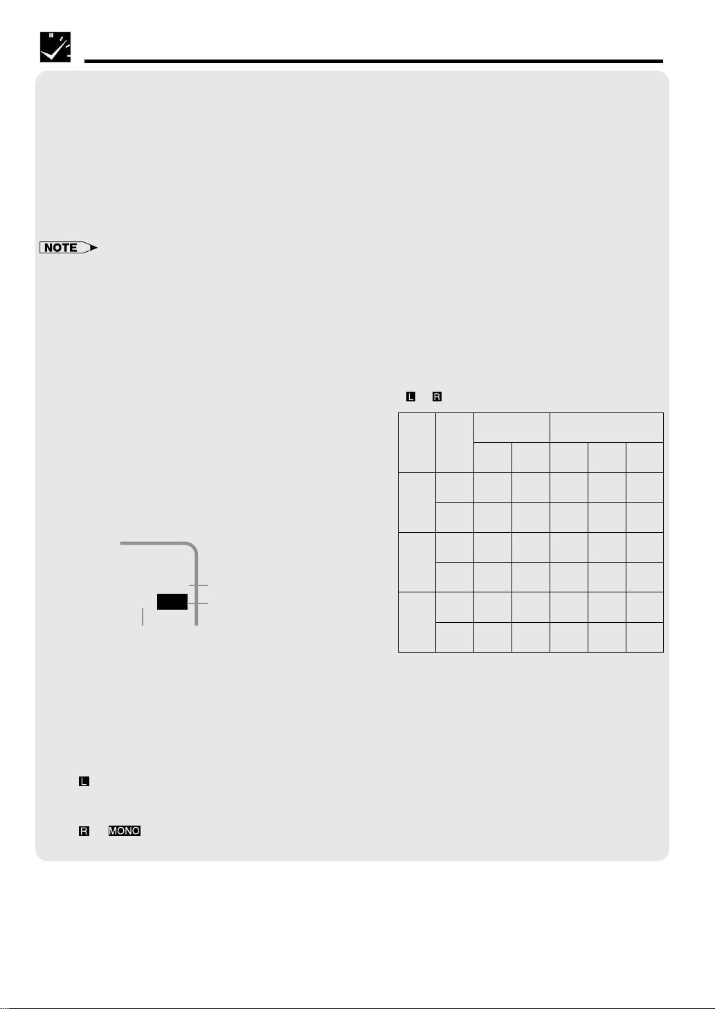
MTS/SAP RECORDING
* The monitor output listed in the table shows
that the audio output mode is in the Hi-Fi
Ⳮ mode.
SAP
Broad-
cast Re-
ceived
Stereo
SAP
Stereo/
SAP
*Monitor Output Recording
Mode
Posi-
tion
SpeakerR-Speaker
OFF
ON
OFF
ON
OFF
ON
L-
LR
LR
MAIN
MAIN
MAIN
SAP
LR
L R
SAP
Hi-Fi
L-CH
L
L
MAIN
MAIN
L
++
L R
Hi-Fi
R-CH
R
R
MAIN
SAP
R
SAP
Linear
Track
L +
+
L R
MAIN
SAP
L R
+
SAP
R
Monitor Output When Receiving a SAP Broadcast
When receiving a SAP broadcast, if the SAP position is set to ON, change the audio output mode to select
Monitor Output (MAIN or SAP) with the SET UP–selection screen.
(See Mode Selection.)
When enjoying a TV program with MAIN sound:
Select
(See Audio Output Mode.)
When enjoying a TV program with SAP sound:
Select
(See Audio Output Mode.)
26
on the SET UP–selection screen.
or on the SET UP–selection screen.
Page 27

Recording a TV Program
Tape Dubbing Connection Instructions
Your VCR can dub (copy) video material from another video device. It can also output video and audio signals
for recording on other video or audio equipment. Audio/Video dubbing cannot be done separately.
! Switch your VCR to the auxiliary input by pressing INPUT on the remote control. (You can also use
CHANNEL ∂/ƒ on the VCR or CH ∂/ƒ on the remote control.)
@ Begin recording on the dubbing VCR and playback on the source VCR simultaneously.
• When using special playback functions (still picture, video search, frame advance and variable slow motion) during
dubbing, a blue screen may appear.
Set BLUE SCREEN mode on the dubbing VCR (for recording) to OFF. (See Mode Selection.)
• To use the TV as a monitor while dubbing, press TV/VCR to “VCR” on the dubbing VCR.
• Use an RCA pin-type connection cable (not supplied with VCR, but supplied with VIEWCAM) to connect source VCR to
dubbing VCR.
• Refer to the manual of the VCR connected to this unit when dubbing a tape.
Only for Hi-Fi models
• If source VCR is a monaural mode, connect the audio cable to “AUDIO-L” of the dubbing VCR.
(VC-A410U, VC-A411U, VC-A420U) (VC-H810U, VC-H811U, VC-H820U)
Source VCR
(for playback)
Sharp Viewcam
(for playback)
Source VCR
(for playback)
Sharp Viewcam
(for playback)
Audio/Video cable
(not supplied)
Dubbing VCR
(for recording)
Coaxial cable
(supplied)
Audio/Video
cable (supplied
with Viewcam)
or
(Only for VC-A420U)
TV Rear
ANT/CABLE
To Front
Audio/Video cable
(not supplied)
Dubbing VCR
(for recording)
Coaxial cable
(supplied)
Audio/Video
cable (supplied
with Viewcam)
or
(Only for VC-H820U)
TV Rear
ANT/CABLE
To Front
27
Page 28

Simple Recording Timer
SIMPLE RECORDING TIMER
The Simple Recording Timer (SRT) enables you to set the recording stop time. The SRT can be set on the TV
screen by using the remote control.
The SRT cannot be set if the clock has not been set. Make sure the clock is set before setting the SRT.
• Turn on the TV and select the video channel. (See Setting the 3 ↔ 4 Output Channel Selector.)
• Insert a cassette with the erasure protection tab opening covered. Power will turn on automatically (POWER
LED indicator will light up).
• Press TV/VCR to select “VCR” (VCR LED indicator will light up).
Only for Hi-Fi models
• If necessary, set “SAP” on the SET UP–selection screen. (See Mode Selection.)
Example: Recording a TV program in the SP mode. The program is on Channel 2, ending at 9:50 AM. The
present time is 8:43 AM.
! Select the desired channel with the numbered buttons or
02
CH ∂/ƒ.
Ex.: Channel → 02
@ Set the recording speed (SP or EP) with TAPE SPEED on
the remote control.
Ex.: SP
Recording Speed
# Press REC to enter the recording mode (REC LED
02
SP STOP 8:50AM
indicator will light up).
Then, press REC again to enter the simple recording
timer mode (TIMER LED indicator will light up). The
recording stop time is displayed.
Ex.: 8:50 AM
02
SP STOP 9:50AM
$ Each press of REC increases the stop time by 10
minutes.
Ex.: 9:50 AM
• The recording stop time will flash for a few seconds before the
stop time is fixed.
% When the stop time comes, recording is finished and the power turns off.
Changing the Contents of the Simple Recording Timer
! Press REC. The stop time flashes on the TV screen.
@ Change the stop time as desired using REC.
Cancelling the Simple Recording Timer
! Press STOP.
• The Simple Recording Timer has priority over other
recordings.
• Ordinary timer programs will not be recorded when portions of
the time setting of the simple recording timer and of the time
setting of the ordinary timer recording overlap.
28
Example:
Ordinary timer recording
(9:30 AM to 10:30 AM)
Simple Recording Timer
(9:00 AM to 10:00 AM)
NOT
recorded
9:00 10:00
Recorded
Record-
ed
11:00 12:00
Page 29

Recording with the Timer
When pressing: The recording date changes in this sequence:
8/10 MO-FR MO-SA DAILY SAT SUN 8/9 8/8
8/10 8/11 8/12 8/8 8/9 SUN SAT
(next year)
(next year)(present) (tomorrow)
• Turn on the TV and select the video channel.
• Insert a cassette with the erasure protection tab opening covered. Power will turn on automatically (POWER
LED indicator will light up).
• Press TV/VCR to select “VCR” (VCR LED indicator will light up).
• Check that the clock is displaying the correct time.
Only for Hi-Fi models
• If necessary, set “SAP” on the SET UP–selection screen. (See Mode Selection.)
Example: Recording a TV program in the SP mode: the TV program is on channel 7 starting at 9:05 PM and
stopping at 10:35 PM on August 10th. The present time is 6:35 PM on August 10th.
1/2
DATE CH START STOP
--/-- --- -:-- -:-- --
--/-- --- -:-- -:-- --
--/-- --- -:-- -:-- --
佡
--/-- --- -:-- -:-- - 2/2
CLEAR :CANCEL
SELECT :
ENTER :SET EXIT :MENU
佡
! Press PROG.. The Timer screen will appear and then
press SET.
@ Select the desired month/day (DATE) with ∂/ƒ and then
1/2
DATE CH START STOP
8/10 --- -:-- -:-- SP
∂
--/-- --- -:-- -:-- --
--/-- --- -:-- -:-- --
--/-- --- -:-- -:-- --
ƒ
SELECT : CHANGE:
ENTER :SET EXIT :MENU
©
佡
press ©. The cursor will move to the next column.
Ex.: August 10th
• If you want to record every day or week at the same
time, hold ƒ when you select the date.
# Select the desired channel with ∂/ƒ and then press ©.
1/2
DATE CH START STOP
∂
8/10 07 -:-- -:-- SP
--/-- --- -:-- -:-- --
ƒ
--/-- --- -:-- -:-- --
--/-- --- -:-- -:-- --
©
佡
Ex.: Channel 07
1/2
∂
DATE CH START STOP
8/10 07 9:05
--/-- --- -:-- -:-- --
ƒ
--/-- --- -:-- -:-- --
--/-- --- -:-- -:-- --
1/2
DATE CH START STOP
∂
8/10 07 9:05
--/-- --- -:-- -:-- --
ƒ
--/-- --- -:-- -:-- --
--/-- --- -:-- -:-- --
1/2
DATE CH START STOP
∂
8/10 07 9:05
--/-- --- -:-- -:-- --
ƒ
--/-- --- -:-- -:-- --
--/-- --- -:-- -:-- --
PM
PM 10:35PM
PM 10:35PM
-:-- SP
SP
SP
©
佡
©
佡
$ Set the recording start time (hour digits and minute digits)
with ∂/ƒ and then press ©.
Ex.: 9:05 PM
Press the AM/PM (100) to select AM or PM.
% Set the recording stop time with ∂/ƒ and then press ©.
Ex.: 10:35 PM
^ Select the tape speed with ∂/ƒ.
Ex.: SP
29
Page 30

Recording with the Timer
1/2
DATE CH START STOP
8/10 07 9:05
佡
--/-- --- -:-- -:-- --
--/-- --- -:-- -:-- --
--/-- --- -:-- -:-- --
PM 10:35PM
SP
• To program the additional timer settings, press SET and
repeat steps @–&.
* Press MENU to finish settings.
The display shown to the left appears on the screen for 5
& Press SET.
TURN VCR POWER OFF
FOR TIMER RECORDING.
佡
佡
Normal
Screen
seconds, after which the normal screen returns.
( Press POWER to enter the timer standby mode. Be sure
POWER VCR RECTIMER
that the TIMER LED indicator light up.
佡
• If the power is interrupted for more than 5 seconds (power failure, etc.) during timer recording, the Auto Clock Setting will
reset the time after the power is returned (the POWER LED indicator will flash) but the timer settings will be cancelled.
• Numbered buttons can be used instead of ∂/ƒ to set the data.
• If the cassette ends before recording all the programs, the VCR will stop, eject the cassette and turn the power off
automatically.
• In Step (, if POWER is pressed with no cassette inserted, the TIMER LED indicator flashes for 5 seconds indicating that
timer recording is not possible.
• In Step (, if the inserted cassette is without the erasure protection tab, TIMER LED indicator flashes and the cassette is
ejected.
• To stop timer recording, press STOP.
• If a button is not pressed within 3 minutes during the setting procedure, the screen will return to the normal screen.
• There are two timer setting screens (1/2, 2/2).
30
Page 31

Recording with the Timer
Confirming Timer Programs
You can see on the Timer setting screen a list of all timer programs that are already set.
• Turn on the TV and select the video channel.
• Press POWER (POWER LED indicator will light up) and then TV/VCR to select “VCR” (VCR LED indicator will
light up).
! Press PROG.. TIMER screen will appear.
• Check the information displayed.
@ If you want to correct the data, select the data to be
changed with ∂/ƒ and then press SET. Correct the data
as desired using ∂/ƒ/ß / ©. Then press SET.
See 2/2 screen also.
佡
1/2
DATE CH START STOP
8/01 125 12:05AM
∂
8/10 07 9:05
DAILY 88 10:03
--/-- --- -:-- -:-- - 2/2
ƒ
CLEAR :CANCEL
SELECT :
ENTER :SET EXIT :MENU
1/2
DATE CH START STOP
8/01 125 12:05AM
8/10 07 9:05
DAILY 88 10:03
--/-- --- -:-- -:-- - 2/2
CLEAR :CANCEL
SELECT :
ENTER :SET EXIT :MENU
12:30PM
PM 10:35PM
PM 10:30PM
12:30PM
PM 10:35PM
PM 10:30PM
EP
SP
EP
佡
EP
SP
EP
∂/ƒ
and
ß/©
佡
# Pressing MENU will clear the screen.
The display shown to the left appears for 5 seconds, after
TURN VCR POWER OFF
FOR TIMER RECORDING.
佡
佡
which the normal screen returns.
• After checking or correcting the program contents, press
POWER to enter the Timer Standby mode. (At the same time,
TIMER LED indicator will light up.)
Cancelling Timer Programs
Perform the following procedure to cancel timer programs that have already been set.
• Turn on the TV and select the video channel.
• Press POWER (POWER LED indicator will light up) and then TV/VCR to select “VCR” (VCR LED indicator will
light up).
1/2
DATE CH START STOP
8/01 125 12:05AM
8/10 07 9:05
DAILY 88 10:03
佡
--/-- --- -:-- -:-- - 2/2
CLEAR :CANCEL
SELECT :
ENTER :SET EXIT :MENU
1/2
DATE CH START STOP
--/-- --- -:-- -:-- --
8/10 07 9:05
DAILY 88 10:03
--/-- --- -:-- -:-- --
佡
2/2
CLEAR :CANCEL
SELECT :
ENTER :SET EXIT :MENU
TURN VCR POWER OFF
FOR TIMER RECORDING.
佡
12:30PM
PM 10:35PM
PM 10:30PM
PM 10:35PM
PM 10:30PM
EP
∂
SP
EP
• Select the program you wish to cancel with ∂/ ƒ.
ƒ
@ Double-check that it is the program you wish to cancel
! Press PROG.. TIMER screen will appear.
SP
EP
and press CANCEL. It will be cleared on the screen.
# Pressing MENU will clear the screen.
The display shown to the left appears for 5 seconds, after
which the normal screen returns.
佡
• If there are still some programs set, press POWER to enter the
Timer Standby mode. (At the same time, TIMER LED indicator
will light up.)
• If you press MENU when all of the timer programs are
cancelled, the screen will return to normal.
31
Page 32

Sharp Super Picture
This function creates clearer picture quality only during playback.
S. PICTURE ON
SET
S.PICTURE
Press S. PICTURE on the VCR.
“S.PICTURE ON (or OFF)” will appear on the TV screen for a few seconds. Each time the
button is pressed, the mode switches between ON and OFF. (The Sharp Super Picture is
preset to ON at the factory.)
ON:
Normally leave the mode set to ON. This high picture quality function will create a clearer image during
playback.
OFF:
Set to OFF when playing back a tape on the VCR while editing or when strong noise appears on the screen.
• This function only operates during playback. It will not operate when recording or watching a TV program with the VCR
tuner.
• When playing S-VHS tape
1. Sharp Super Picture is set to off automatically. When finished playback, the setting will return to the previous setting.
2. You cannot change ON/OFF setting manually.
• The ON/OFF status of the Sharp Super Picture can be checked when ON SCREEN is pressed to display OSD.
• This function can not be set to ON/OFF with the MENU screen displayed. First close the MENU screen before operating this
function.
• When the VCR power is turned off, the Sharp Super Picture setting is retained in memory.
• If power is interrupted for more than 5 seconds (power failure, etc.), the setting will return to ON.
Recorded Section Auto Repeat
Set the AUTO REPEAT mode to ON on the SET UP selection screen. (See Mode
Selection.) If the recorded portion has finished and a non-recorded portion has
PLAY
continued for 15 seconds, the tape will automatically stop, rewind to the
beginning and repeat playback. (The AUTO REPEAT mode is preset to OFF at the
factory.)
• The ON/OFF status of the Recorded Section Auto Repeat can be checked when ON SCREEN is pressed to display OSD.
(The “ ” mark lights when the Recorded Section Auto Repeat is on.)
• If the Recorded Section Auto Repeat is on and the tape is rewinded to the beginning with rewind or reverse video search,
the tape will automatically start playback.
Auto Zero Back
This function automatically forwards or rewinds the cassette to the “0:00.00” point. Use this function to return to
a recording start point.
! Reset the counter to “0:00.00” with CANCEL before recording.
@ Press REC to start recording (REC LED indicator will light up).
# After recording the desired program, press STOP to stop recording (REC LED indicator
will turn off).
$ Press ZERO BACK to return to the recording start point (0:00.00).
• During Auto Zero Back, if the VCR rewinds (or fast forwards) the tape all the way without finding the “0:00.00” point, it will
stop at the beginning (or end) of the tape.
• The counter start point “0:00.00” may differ slightly from the starting point on the tape.
• This function is not operable during recording, recording pause, simple recording timer or timer recording.
32
Page 33

DPSS (Digital Program Search System)
1–1 2
3
You can quickly locate a desired section of the tape with this
feature.
Index Signal
Rewind
Current tape position
Fast forward
An index signal is automatically recorded on the tape at the start
of ordinary recording, simple recording timer and timer
recording.
Index signals
! Insert a tape containing index signals.
@ Select the index number of the desired program with DPSS k/j on the remote
control.
• With each press of the button, the number changes. One of 19 programs can be
selected in either direction (one of up to 38 programs).
(Ex.: DPSS 3=Third program after the current one.)
On the TV screen
DPSS 3
佡
DPSS 2
# Search starts immediately when you press DPSS k/j. (When a signal is located, the displayed number
decreases.)
$ When the selected section is found, playback begins automatically.
• DPSS may not work if recordings are too close (within 3 minutes of each other).
• Press PLAY or STOP to cancel DPSS.
• If the tape reaches its end or beginning before locating the desired point, DPSS is cancelled.
• DPSS may not function for damaged or worn tapes.
• DPSS cannot be used with tapes that contain no index signals.
• The starting point of a program may vary slightly.
• DPSS does not operate during the slow, record, timer stand-by, and timer recording modes, or when there is no cassette loaded.
• Index signals for DPSS cannot be entered manually.
Functions
Special
Skip Search
With this feature, you can set a forward video search time to approx. 30, 60, 90 or 120
seconds of recorded material. After searching, normal playback will resume automatically.
• Press SKIP SEARCH on the remote control during playback (ex. during commercials).
Number of Times Pressed 1 Time 2 Times 3 Times 4 Times
Video Search Time Approx. 30 sec. Approx. 60 sec. Approx. 90 sec. Approx. 120 sec.
Instant Replay
With this feature, you can set a reverse video search time to approx. 20, 40, 60, or 80
seconds of recorded material. After searching, normal playback will resume automatically.
• Press REPLAY on the remote control during playback.
Number of Times Pressed 1 Time 2 Times 3 Times 4 Times
Video Search Time Approx. 20 sec. Approx. 40 sec. Approx. 60 sec. Approx. 80 sec.
33
Page 34

Tamper Proof
With this feature, you can lock all VCR modes to prevent accidental change.
This function works even when the VCR power is off, thus preventing children from operating
the VCR or viewing select programs while you are away from home.
Tamper Proof
! Press TAMPER PROOF on the remote control for about 2 seconds.
The TAMPER PROOF LED indicator will flashing for about 2 seconds and remain lit. Tamper Proof has been
activated.
@ Now regardless of what other operating buttons are touched, the VCR will continue to operate in the present
mode and the TAMPER PROOF LED indicator will flash.
(If Tamper Proof is activated during playback, once the tape reaches its end, the VCR automatically
rewinds the tape, ejects it and turns the power off.)
Disengaging Tamper Proof
• Press TAMPER PROOF for about 2 seconds.
The TAMPER PROOF LED indicator starts flashing and then disappears. Now, Tamper Proof is disengaged.
• If power is interrupted for more than 5 seconds (power failure, etc.), Tamper Proof may disengage.
• If, Tamper Proof is on, you attempt to change modes by pressing any button, the TAMPER PROOF LED indicator will flash.
34
Page 35

Specifications
Format: VHS NTSC Standard
Video Recording System: Rotary Two-Head Helical Scanning
Number of Video Heads: 4
Video Signal Standard: NTSC Color System
Audio Recording System: 1 Stationary Head for Linear Audio
2 Rotary Heads for Hi-Fi stereo (Only for Hi-Fi models)
Tape Width: 12.7 mm (1/2 inch)
Tape Speed: (SP) 33.35 mm/sec (1.31 i.p.s.)
(LP) 16.67 mm/sec (0.66 i.p.s.) (playback only)
Maximum Recording Time: (SP) 160 min (T-160)
Channel Coverage: VHF 2–13
Antenna Input: 75 Ohm
Video Input: 0.5 to 2.0 Vp-p, 75 Ohm unbalanced
Video Output: 1.0 Vp-p, 75 Ohm unbalanced
Audio Input: 8 dBs, 47 kOhm unbalanced (0 dBs 0.775 Vrms)
Audio Output: 8 dBs, 1 kOhm unbalanced (0 dBs 0.775 Vrms)
Hi-Fi Audio (Only for Hi-Fi models)
Dynamic Range
Frequency Response
Memory Backup: 5 seconds
Operating Temperature: 5 C to 40 C (41 F to 104F)
Storage Temperature: 20 C to 60 C (4 F to 140 F)
Power Source: 120 V AC, 60 Hz
Power Consumption: 18 W
Dimensions (approx.): VC-A411U, VC-H811U:
Weight (approx.): 2.7 kg (6 lbs)
(EP) 11.12 mm/sec (0.44 i.p.s.)
(EP) 480 min (T-160)
UHF 14–69
CATV 1–125
: 90 dB
: 20 Hz–20 kHz
360 (W) 92 (H) 254 (D) mm
(14-3/16 3-5/8 10 )
VC-A410U, VC-A420U, VC-H810U, VC-H820U:
360 (W) 92 (H) 255 (D) mm
(14-3/16 3-5/8 10-3/64 )
Helpful
Hints
• Hi-Fi models: VC-H810U, VC-H811U, VC-H820U
• Specifications are subject to change without notice.
35
Page 36

Troubleshooting
Check this list before calling for service.
Problem
Possible Cause/Solutions
• NO OPERATION WHEN ANY BUTTON IS
PRESSED.
• No power.
• VCR does not receive CATV channels.
• VCR does not operate.
• VCR does not record.
• No color or poor TV picture during normal
viewing.
• No tape movement.
• No picture appears during playback.
• Cassette cannot be loaded.
• Timer recording does not work.
• Noise appears on the screen when the
automatic tracking control system is
operating.
• Cannot record a signal through the rear
external input jack.
• MAKE SURE THAT THE “TAMPER PROOF” MODE IS NOT ENGAGED (The
TAMPER PROOF LED indicator will light up).
• Make sure the power cord is plugged in.
• Check the outlet, fuse or circuit breaker.
• Use the CHANNEL PRESET screen to change from AIR mode to CATV. (See
Setting the Channels.)
• Turn on the power.
• Press EJECT several times.
• Safety device in VCR is functioning. Unplug VCR and plug it in again after a few
minutes.
• Cassette erasure protection tab is removed. Use a different cassette or place
adhesive tape over the tab opening.
• Check for a cassette loaded in the unit.
• Make sure the “TV” has been selected by pressing TV/VCR.
• Make sure all cables are connected properly.
• Make sure the VCR is not in PAUSE/STILL mode.
• Make sure the tape has not reached the end or beginning.
• Make sure the TV is set to the same channel as the VCR’s 3 ↔ 4 OUTPUT
CHANNEL selector.
• Check all connecting cables.
• Make sure there is no other cassette inside.
• Make sure the cassette is properly positioned and reinsert.
• Make sure the “TAMPER PROOF” mode is not engaged.
• Power failure may have occurred.
• Adjust the tracking manually by pressing CH ∂/ƒ.
• In some cases, with a worn or damaged tape, noise cannot be eliminated
completely.
• The VCR may not be set to external input mode.
Press INPUT to set the VCR to external input mode. (See Tape Dubbing.)
• Picture or sound is not stable during
playback.
•“DEW”
• If remote control fails to operate.
• Keep your VCR away from electrical and magnetic appliances. Be sure to
position your VCR at least 8 away from your TV or video monitor.
• See page 2 for information.
• See page 8 for information.
Only for Hi-Fi models
• Stereo TV puts out monaural sound only,
even when cassettes recorded in Hi-Fi
stereo are played back.
• Cassettes recorded in stereo mode are
not played back in stereo.
• Use RCA pin type connection cables (not the supplied coaxial cable) to connect
the TV to the VCR, and set the TV to external video input mode.
• Adjust the tracking or try another Hi-Fi stereo cassette.
• Make sure the sound was recorded in Hi-Fi stereo. (Any stereo signals recorded
on the linear track will not be played back in stereo.)
This unit is equipped with a microprocessor. Its performance could be adversely affected by external
electrical noise or interference. If this should happen, unplug the VCR and plug it in again after a few
minutes and reset EZ Set Up for AIR/CATV operation.
Service Information
To obtain the name and address of the nearest Sharp Factory Service Centre or Authorized Service Centre,
please contact:
HEADQUARTERS: 335 Britannia Road East, Mississauga, Ontario L4Z 1W9
Tel: (905) 568-7140 or 1-(877) SHARP-CC
36
Page 37

Memo
37
Page 38

VALID IN CANADA ONLY
LIMITED WARRANTY
Consumer Electronics Products
Congratulations on your purchase!
Sharp Electronics of Canada Ltd. (hereinafter called “Sharp”) gives the following express warranty to the first consumer
purchaser for this Sharp brand product, when shipped in its original container and sold or distributed in Canada by Sharp
or by an Authorized Sharp Dealer:
Sharp warrants that this product is free, under normal use and maintenance, from any defects in material and workmanship.
If any such defects should be found in this product within the applicable warranty period, Sharp shall, at its option, repair
or replace the product as specified herein.
This warranty shall not apply to:
(a) Any defects caused or repairs required as a result of abusive operation, negligence, accident, improper installation
or inappropriate use as outlined in the owner’s manual.
(b) Any Sharp product tampered with, modified, adjusted or repaired by any party other than Sharp, Sharp’s Authorized
Service Centres or Sharp’s Authorized Servicing Dealers.
(c) Damage caused or repairs required as a result of the use with items not specified or approved by Sharp, including
but not limited to head cleaning tapes and chemical cleaning agents.
(d) Any replacement of accessories, glassware, consumable or peripheral items required through normal use of the
product including but not limited to earphones, remote controls, AC adapters, batteries, temperature probe, stylus,
trays, filters, belts, ribbons, cables and paper.
(e) Any cosmetic damage to the surface or exterior that has been defaced or caused by normal wear and tear.
(f) Any damage caused by external or environmental conditions, including but not limited to transmission line/power line
voltage or liquid spillage.
(g) Any product received without appropriate model, serial number and CSA/CUL markings.
(h) Any products used for rental or commercial purposes.
(i) Any installation, setup and/or programming charges.
Should this Sharp product fail to operate during the warranty period, warranty service may be obtained upon delivery of
the Sharp product together with proof of purchase and a copy of this LIMITED WARRANTY statement to an Authorized
Sharp Service Centre or an Authorized Sharp Servicing Dealer. In home warranty service may be provided at Sharp’s
discretion on any Sharp television with the screen size of 27" or larger and on any Sharp Over The Range Microwave
Oven.
This warranty constitutes the entire express warranty granted by Sharp and no other dealer, service centre or their agent
or employee is authorized to extend, enlarge or transfer this warranty on behalf of Sharp. To the extent the law permits,
Sharp disclaims any and all liability for direct or indirect damages or losses or for any incidental, special or consequential
damages or loss of profits resulting from a defect in material or workmanship relating to the product, including damages
for the loss of time or use of this Sharp product or the loss of information. The purchaser will be responsible for any
removal, reinstallation, transportation and insurance costs incurred. Correction of defects, in the manner and period of
time described herein, constitute complete fulfillment of all obligations and responsibilities of Sharp to the purchaser with
respect to the product and shall constitute full satisfaction of all claims, whether based on contract, negligence, strict
liability or otherwise.
WARRANTY PERIODS
Colour Television 1 year (picture tube 1 additional year)
LCD Projector 1 year (bulb 90 days)
LCD TV 1 year
Video Cassette Recorder 1 year
Camcorder 1 year
TV/VCR Combo 1 year (picture tube 1 additional year)
Audio Products 1 year
Microwave Oven 2 years (magnotron 3 additional years for part only)
Vacuum Cleaner 1 year
DVD Player 1 year
38
To obtain the name and address of the nearest Authorized Sharp Service Centre or Dealer, please contact:
SHARP ELECTRONICS OF CANADA LTD.
H
E
T
B
E
E
B
O
T
SHARP ELECTRONICS OF CANADA LTD.
335 Britannia Road East
Mississauga, Ontario
L4Z 1W9
(905)568-7140 or 1-(877) SHARP-CC
Web site: www.sharp.ca
SHARP CORPORATION
Osaka, Japan
T
H
R
O
U
SERVICE
G
H
C
U
S
S
T
O
R
E
M
Printed in Malaysia
TINS-3969AJZZ
1P02-MSF
S
T
N
O
I
T
C
A
F
S
I
T
A
 Loading...