

Page 1

IMPORTANT SAFETY NOTICES
PREVENTION OF PHYSICAL INJURY
1. Before disassembling or assembling parts of the copier and peripherals,
make sure that the copier power cord is unplugged.
2. The wall outlet should be near the copier and easily accessible.
3. Note that the optional tray heater and the optional anti-condensation
heaters are supplied with electrical voltage even if the main switch is
turned off.
4. If any adjustment or operation check has to be made with exterior
covers off or open while the main switch is turned on, keep hands away
from electrified or mechanically driven components.
5. The inside and the metal parts of the fusing unit become extremely hot
while the copier is operating. Be careful to avoid touching those
components with your bare hands.
HEALTH SAFETY CONDITIONS
1. Toner and developer are non-toxic, but if you get either of them in your
eyes by accident, it may cause temporary eye discomfort. Try to remove
with eye drops or flush with water as first aid. If unsuccessful, get
medical attention.
OBSERVANCE OF ELECTRICAL SAFETY STANDARDS
1. The copier and its peripherals must be installed and maintained by a
customer service representative who has completed the training course
on those models.
SAFETY AND ECOLOGICAL NOTES FOR DISPOSAL
1. Do not incinerate toner cartridges or used toner. Toner dust may ignite
suddenly when exposed to open flame.
2. Dispose of used toner, developer, and organic photoconductors in
accordance with local regulations. (These are non-toxic supplies.)
3. Dispose of replaced parts in accordance with local regulations.
Page 2

SECTION 1
OVERALL
MACHINE INFORMATION
Page 3

20 December 1996 SPECIFICATIONS
1. SPECIFICATIONS
Configuration: Desk Top
Copy Process: Dry electrostatic transfer system
Originals: Sheet/Book
Original Size: Maximum: A3/11" x 17"
Copy Paper Size: Maximum: A3/11" x 17"
Minimum:
1/2
A5/5
1/2
A6/5
Non-standard sizes:
Vertical 45 mm ~ 308 mm, 1.8" ~ 12"
Horizontal 148 mm ~ 432 mm, 5.8" ~ 17"
Copy Paper Weight: Paper tray feed: 64 to 90 g/m
By-pass feed: 52 to 157 g/m
" x 8
" x 8
1/2
" sideways (Paper tray feed)
1/2
" lengthwise (By-pass feed)
2
, 17 to 24 lb
2
, 14 to 42 lb
Overall
Information
Reproduction Ratios:
Enlargement
Full Size 100% 100%
Reduction
Metric Version Inch Version
200%
141%
122%
93%
82%
71%
50%
200%
155%
129%
93%
74%
65%
50%
Zoom: From 50% to 200% in 1% steps
Copying Speed: 15 copies/minute (A4/8.5" x 11" sideways)
9 copies/minute (A3/11" x 17")
Warm-up Time:
120 V machines: Less than 30 seconds (at 23°C)
230 V machines: Less than 45 seconds (at 23°C)
First Copy Time: Less than 6.9 seconds (A4/8.5" x 11" sideways)
Copy Number Input: Number keys, 1 to 99
Manual Image Density
7 steps
Selection:
Automatic Reset: 1 minute standard setting; can also be set to 3
minutes or no auto reset
1-1
Page 4

SPECIFICATIONS 20 December 1996
Paper Capacity: Paper tray: 500 sheets or less than 56 mm stack
height
By-pass feed entrance:
Standard paper 80 sheets
OHP 10 sheets
Others 1 sheet
Toner Replenishment: Bottle exchange (215 g/bottle)
Copy Tray Capacity: 100 sheets
Power Source: 120 V/60 Hz: More than 15 A (for North America)
220 ~ 240 V/50 Hz: More than 8 A (for Europe)
220 V/50 Hz: More than 8 A (for Asia)
220 V/60 Hz: More than 8 A (for Middle East/Asia)
110 V/60 Hz: More than 15 A (for Taiwan)
127 V/60 Hz: More than 15 A (for Middle East)
Power Consumption:
Dimensions:
Copier only Full system*
Maximum 1.4 kW
(120 V machines)
0.9 kW
(230 V machines)
Copy cycle 0.71 kW 0.74 kW
Warm-up 0. 95 kW 0. 95 kW
Stand-by 0.25 kW 0.25 kW
Energy saver 0.2 kW 0.2 kW
*Full system : Copier with document feeder and 10 - bi n sorter
Width Depth Height
Copier 579 mm
(22.8")
Full system* 775 mm
(30.2")
*Full system : Copier with document feeder and 10 - bi n sorter
560 mm
(22.1")
560 mm
(22.1")
1.5 kW
(120 V machines)
1.0 kW
(230 V machines)
420 mm
(16.6")
508 mm
(19.8")
1-2
Page 5

20 December 1996 SPECIFICATIONS
Noise Emissions: Sound pressure level (the measurements are
made in accordance with ISO 7779 at the
operator position.)
Copying Less than 57 dB Less than 61 dB
*Full system : Co pi er w i th d ocument feeder an d 10- bi n sorter
Copier only Full system*
Sound power level (the measurements are made
in accordance with ISO 7779)
Overall
Information
Weight:
Optional Equipment:
(Sales items)
Optional Equipment:
(Servi ce items)
Copier only Full system*
Stand-by Less than 40 dB Less than 40 dB
Copy cycle Less than 63 dB Less than 67 dB
*Full system : Co pi er w i th d ocument feeder an d 10- bi n sorter
Copier only
Full system *
*Full system : Co pi er w i th d ocument feeder an d 10- bi n sorter
42 kg (93.0 lb)
55 kg (121 lb)
Document feeder (A662)
10-bin sorter (A657)
Optics anti-condensation heater
Tray heater
•
Specifications are subject to change without
notice.
1-3
Page 6
COPY PROCESS AROUND THE DRUM 20 December 1996
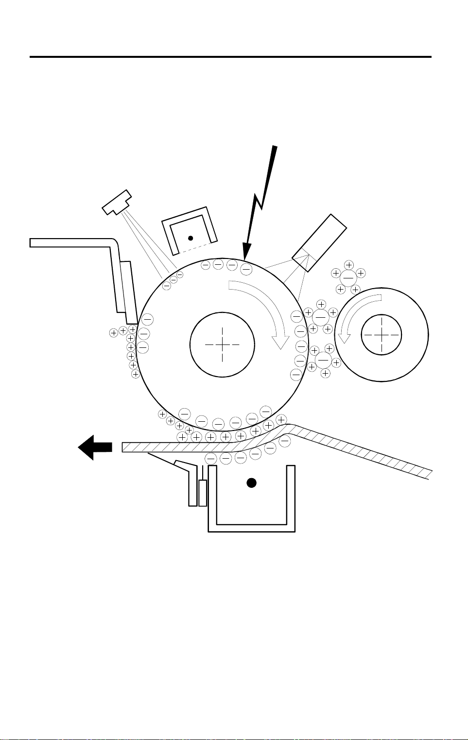
2. COPY PROCESS AROUND THE DRUM
2
8
1
3
7
4
6
1-4
5
A219V503.wmf
Page 7

20 December 1996 COPY PROCESS AROUND THE DRUM
1. DRUM CHARGE
In the dark, the charge corona unit gives a uniform negative charge to the
organic photoconductive (OPC) drum. The charge remains on the surface
of the drum because the OPC drum has a high electrical resistance in the
dark.
2. EXPOSURE
An image of the original is reflected to the drum surface via the optics
assembly. The charge on the drum surface is dissipated in direct
proportion to the intensity of the reflected light, thus producing an
electrical latent image on the drum surface.
3. ERASE
The erase lamp illuminates the area of the charged drum surface that will
not be used for the copy image. The resistance of the drum in the
illuminated areas drops and the charge on those areas dissipates.
4. DEVELOPMENT
Positively charged toner is attached to the negatively charged areas of
the drum, thus developing the latent image. (The positive triboelectric
charge is caused by friction between the carrier and toner particles.)
Overall
Information
5. IMAGE TRANSFER
Paper is fed to the drum surface at the proper time so as to align the copy
paper and the developed image on the drum surface. Then, a strong
negative charge is applied to the back side of the copy paper, producing
an electrical force which pulls the toner particles from the drum surface to
the copy paper. At the same time, the copy paper is electrically attracted
to the drum surface.
6. PAPER SEPARATION
A strong positive dc charge is applied to the back side of the copy paper
via a discharge plate, reducing the negative charge on the copy paper
and breaking the electrical attraction between the paper and the drum.
Then, the stiffness of the copy paper causes the paper to separate from
the drum surface.
7. CLEANING
The cleaning blade scrapes the toner off the drum. The collected toner is
recycled.
8. QUENCHING
Light from the quenching lamp electrically neutralizes the drum surface.
1-5
Page 8
MECHANICAL COMPONENT LAYOUT 20 December 1996
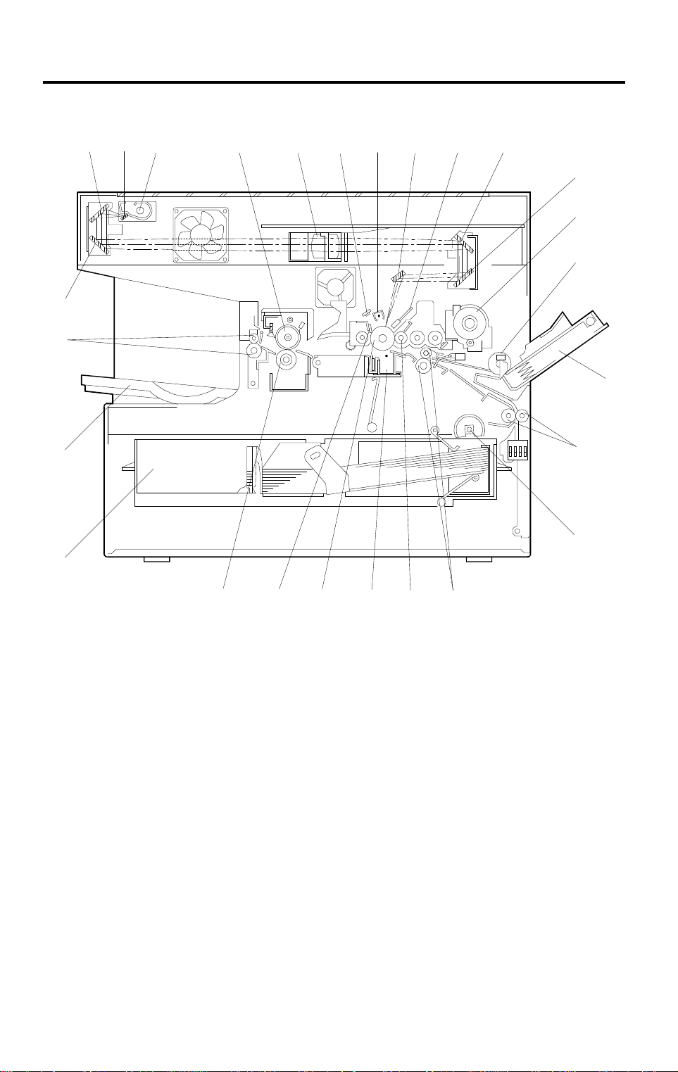
3. MECHANICAL COMPONENT LAYOUT
26
25
24
23
7
10
98654321
11
12
13
14
15
16
22
1. 2nd Mirror
2. 1st Mirror
3. Exposure Lamp
4. Hot Roller
5. Lens
6. Quenching Lamp
7. Charge Corona Unit
8. 6th Mirror
9. Erase Lamp
10. 4th Mirror
11. 5th Mirror
12. Toner Bottle Holder
13. By-pass Feed Roller
21 20
19
18
17
A219V500.wmf
14. By-pass Feed Table
15. Relay Rollers
16. Tray Paper Feed Rollers
17. Registration Rollers
18. Development Roller
19. Transfer/Separation Unit
20. Drum
21. Cleaning Blade
22. Pressure Roller
23. Paper Tray
24. Copy Tray
25. Exit Rollers
26. 3rd Mirror
1-6
Page 9
20 December 1996 DRIVE LAYOUT
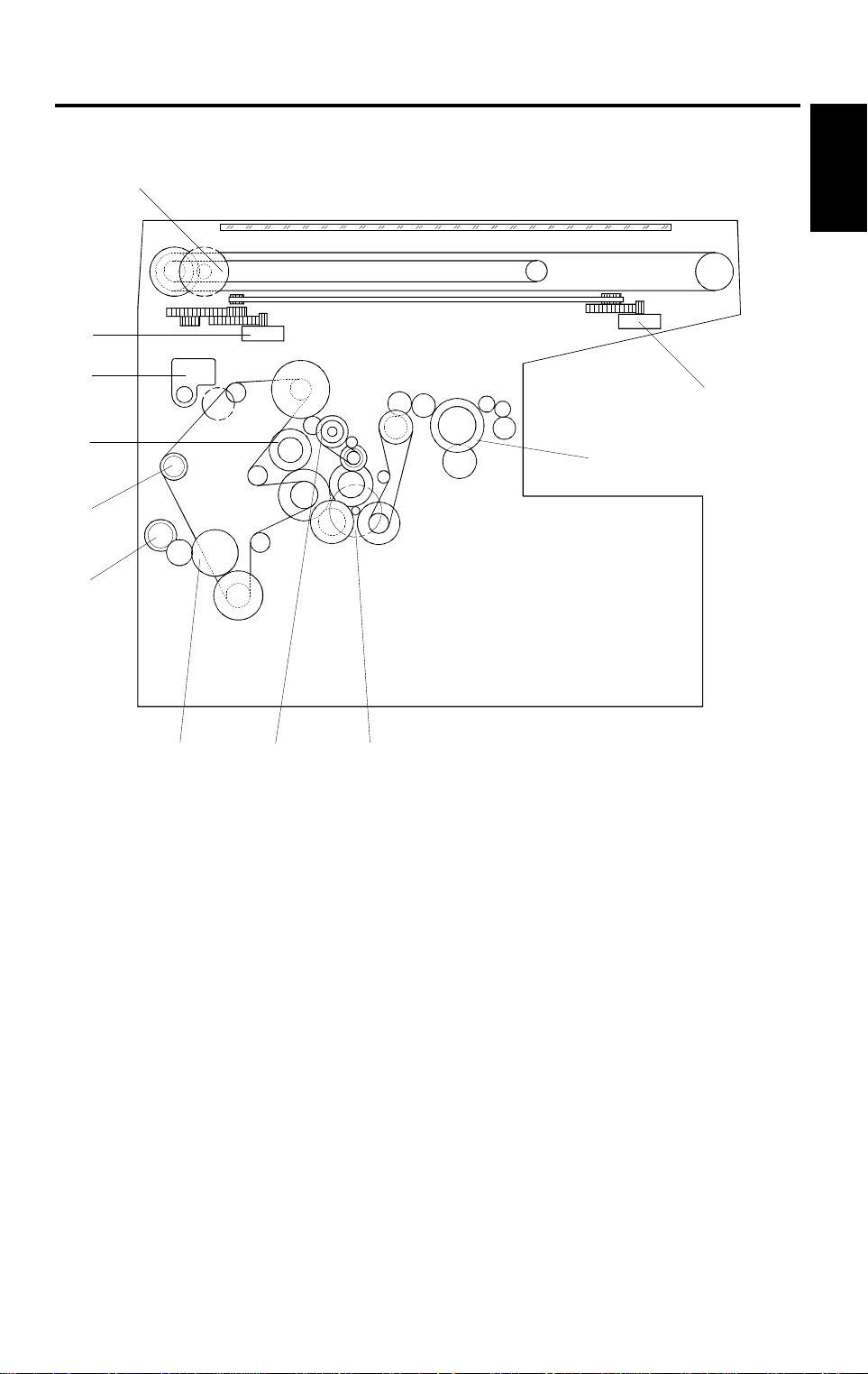
4. DRIVE LAYOUT
10
11
9
8
2
1
Overall
Information
7
6
543
1. Lens Motor
2. Fusing Unit Drive Gear
3. Main Motor
4. Drum Drive Gear
5. Tray Paper Feed Clutch Gear
6. Relay Roller Clutch Gear
A219V501.wmf
7. By-pass Paper Feed Clutch
8. Registration Clutch Gear
9. Toner Supply Motor
10. 4th/5th Mirror Motor
11. Scanner Drive Motor
1-7
Page 10
PAPER PATH 20 December 199 6
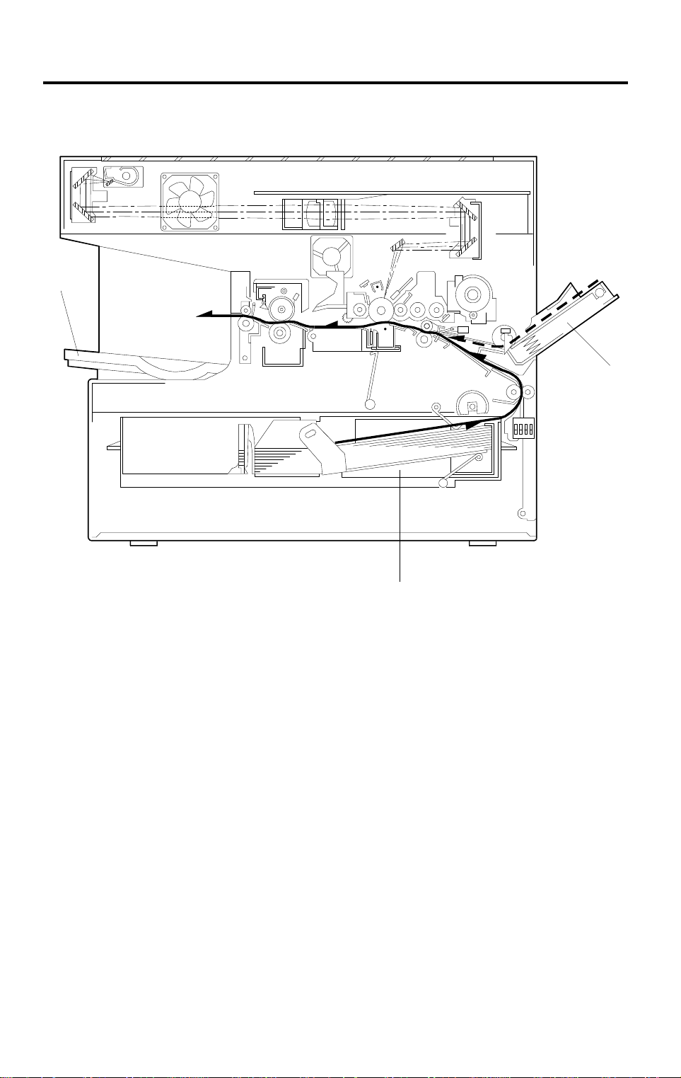
5. PAPER PATH
3
1
1. By-pass Feed
2. Paper Tray Feed
3. Copy Tray
2
A219V502.wmf
1-8
Page 11

20 December 1996 ELECTRICAL COMPONENT DESCRIPTIONS
6. ELECTRICAL COMPONENT DESCRIPTIONS
Refer to the electrical component layout and the point-to-point diagram on the
waterproof paper in the pocket for symbols and index numbers.
Symbol Name Function Index No.
Motors
M1
M2 Scanner Drive M ot or Drives the sca nners (1st and 2nd). 9
M3
M4
M5
M6
M7
Main Motor Drives all th e m ai n unit component s except
for the optics u ni t and f ans.
Lens Motor Moves the lens position in accor dance with
the selecte d m agnification.
4th/5th Mirror Motor Moves the 4th/5th mirror position in
accordanc e w ith the selected magnification.
Toner Supply M ot or Rotates the to ner bot tle to supply toner to the
development uni t .
Optics Cooling Fan
Motor
Exhaust Fan Mot or Removes heat fro m a ro und the fusing uni t
Prevents buil d- up of hot air in the opti cs
cavity.
and blows the ozone built up aro und the
charge corona unit towards the ozone filter.
8
18
16
10
17
7
Overall
Information
Clutches
CL1
CL2
CL3 Relay Roller Clutch Drives the relay rollers for paper tray feed. 13
CL4 Registration Clutch Drives the registration rollers. 11
Switches
SW1 Main Switch Supplies power to the copier. 38
SW2
SW3
SW4
Sensors
S1
S2
Tray Paper Feed
Clutch
By-pass Paper F eed
Clutch
Interlock Switch Cuts all power when the front cover is
Tray Paper Size
Switch
Right Vertical Guide
Switch
4th/5th Mirro r Hom e
Position Sensor
ADS Sensor Detects the bac kground density of th e
Transfers ma in motor drive to the paper feed
roller.
Starts paper fee d fr om t he by-pass feed
table.
opened.
Determines what size of paper is in the
paper tray.
Cuts the +24 V dc power line of the relay
roller clutch.
Informs the CPU when the 4th/5th mirror
assembly is at the home position (full size
position).
original.
14
12
37
31
27
33
24
1-9
Page 12

ELECTRICAL COMPONENT DESCRIPTIONS 20 December 1996
Symbol Name Function Index No.
S3
Tray Paper End
Sensor
Informs the CPU when the paper tray runs
out of paper.
28
Registratio n Sensor Detects the leading edge of th e copy paper
S4
to determin e th e stop timing of the re l ay
30
roller clutc h , and detects misfeed s.
S5
By-pass Feed Paper
End Sensor
Informs the CPU w hen there is no paper in
the by-pass tray.
29
S6 Exi t Sensor D etects misfeeds. 23
S7
S8
S9
Scanner Home
Position Sensor
Lens Home Posit ion
Sensor
Toner Density (TD)
Sensor
Informs the CPU w hen the 1st scanner i s at
the home position.
Informs the CPU when the lens is at the
home posit ion.
Detec ts the ra tio of ton er to car rier in th e
developer.
40
22
26
Printed Circuit Boards
PCB1 Main Control Board Controls all copier funct i ons. 1
PCB2
High Voltage Supply
Board - C/G/B/T/S
Provides high voltage to the charge corona,
grid, development bias, transfer corona, and
2
discharge plate.
PCB3
AC Drive/DC Power
Supply Board
Drives the exp o sure lamp, fusing l amp, and
main motor. Rectifies 30 Vac and 8 Vac input
3
and outputs 5 Vdc and 24 Vdc.
PCB4
Operation Pane l
Board
Informs the CPU of the selected mode s and
displays the si t uation on the panel.
6
Lamps
Erase Lamp Discharges t he drum outside of th e i m age
L1
area. (Provides leading/trailing edge and
side erases.)
L2
L3
Quenching Lamp Neutralizes any charge remain i ng on the
drum surfa ce af t er cl eaning.
Exposure Lamp Applies high intensity light to the original for
exposure.
L4 Fusing Lamp Provides heat to the hot roller. 25
Others
CO1
H1
H2
TF1
Total Counter Keeps track of the t ot a l number of copies
made.
Tray Heater (Opt i on) Turns on when t he main switch is of f to keep
paper in the pa per tray dry.
Optics
Anti-condensat i on
Heater (Opti on)
Exposure Lamp
Thermofuse
Turns on when t he main switch is of f to
prevent moisture from accumulating in the
optics.
Provide back-up overheat protection around
the exposure lamp.
4
5
20
34
32
39
21
1-10
Page 13

20 December 1996 ELECTRICAL COMPONENT DESCRIPTIONS
Symbol Name Function Index No.
TF2
TH1
TH2
TR
Fusing Therm of u se Provide back-up overheat pro te ct i on i n t he
fusing unit.
Fusing Therm i st or Monitor s th e te mperature around t he
exposure lam p for overheat prot ect i on.
Optics Therm i st or Monitors th e te mperature around t he
exposure lam p for overheat prot ect i on.
Transformer Steps down the wall vol t age to 30 Vac and 8
Vac.
36
35
19
15
Overall
Information
1-11
Page 14

SECTION 2
DETAILED DESCRIPTIONS
Page 15

20 December 1996 DRUM
1. DRUM
1.1 OPC DRUM CHARACTERISTICS
The OPC (Organic Photoconductor) drum used in this copier is small in
diameter (30 mm), ensuring good paper separation. An OPC drum has the
following characteristics.
1. The drum is able to accept a high negative electrical charge in the dark.
(The electrical resistance of a photoconductor is high in the absence of
light.)
2. It dissipates the electrical charge when exposed to light.
(Exposure to light greatly increases the conductivity of a photoconductor.)
3. The amount of charge dissipated is in direct proportion to the intensity of
the light. That is, where stronger light is directed to the photoconductor
surface, a smaller voltage remains on the drum.
4. An OPC drum is less sensitive to changes in temperature (when
compared to selenium F type drums).
Detailed
Descriptions
5. During the drum’s life, drum residual voltage gradually increases and the
photoconductive surface becomes worn. Therefore, some compensation
for these characteristics is required.
2-1
Page 16
DRUM 20 December 1996
1.2 DRIVE MECHANISM
[C]
[E]
[D]
[B]
[A]
A219D520.wmf
The drive from the main motor [A] is transmitted to the drum [B] through a
series of gears, a timing belt [C], and the drum drive shaft [D].
When the imaging unit is installed in the copier, the drum drive shaft engages
inside the drum’s flange [E] as shown.
2-2
Page 17
20 December 1996 CHARGE
2. CHARGE
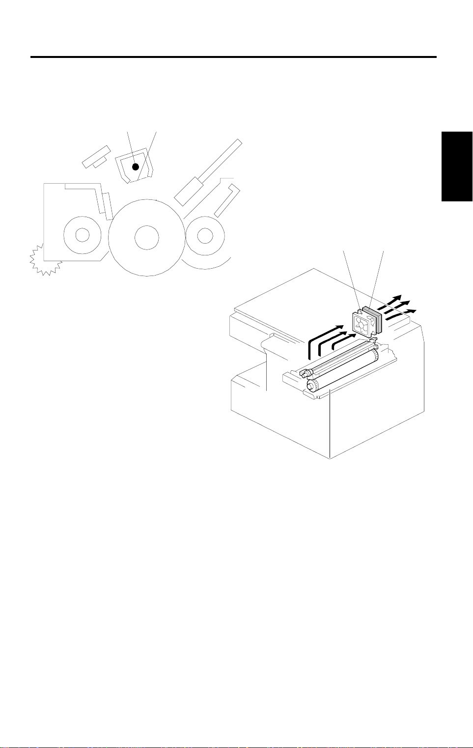
2.1 OVERVIEW
[A]
[B]
A219D505.wmf
[C]
Detailed
Descriptions
[D]
A219D521.wmf
This copier uses a single wire scorotron to charge the drum. The corona wire
[A] generates a corona of negative ions when the high voltage supply unit
applies a negative voltage. The stainless steel grid plate [B] ensures that the
drum coating receives a uniform negative charge as it rotates past the corona
unit.
The exhaust fan [C] causes a flow of air above and through the charge
corona section. This prevents an uneven build-up of negative ions that can
cause uneven image density.
3
An ozone filter [D], which absorbs ozone (O
) generated by the charge
corona, is located beside the exhaust fan. The ozone filter decreases in
efficiency over time as it absorbs ozone. The ozone filter should be replaced
every PM cycle (45 k copies).
2-3
Page 18
CHARGE 20 December 1996
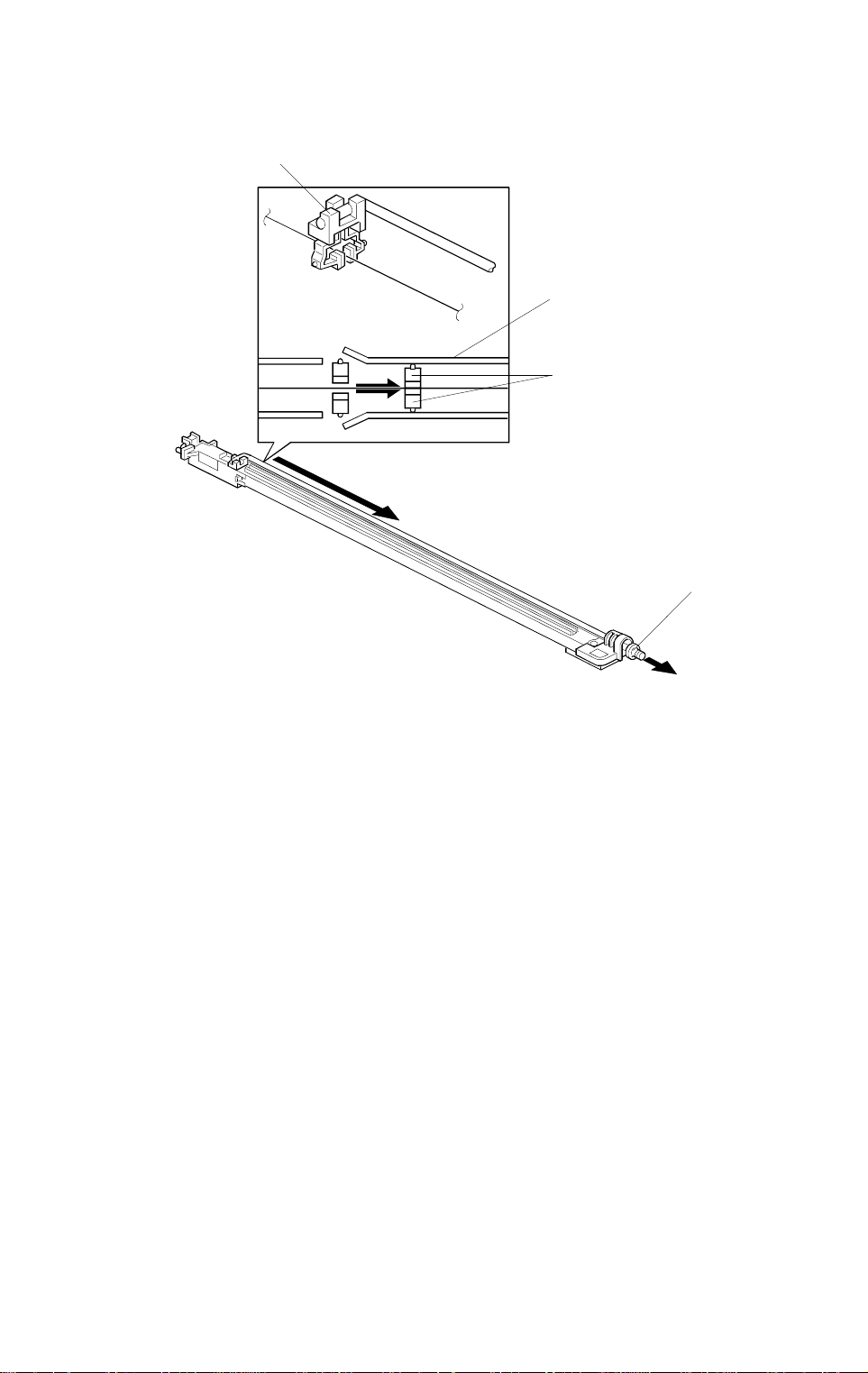
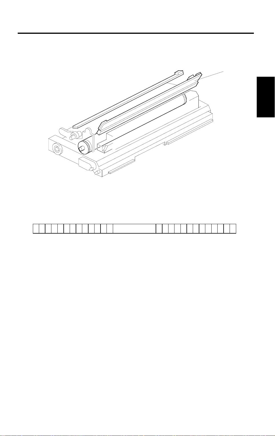
2.2 CHARGE CORONA WIRE CLEANER MECHANISM
[C]
[D]
[A]
[B]
A219D536.wmf
Pads [A] move along the charge corona wire as the wire cleaner knob [B] is
manually slid in and out.
The cleaner pad bracket [C] is connected to the wire cleaner knob. When the
knob is pulled out, the pads move into contact with the corona wire as shown,
since the casing [D] is narrower away from the home position.
The pads move away from the wire when the wire cleaner knob is fully
inserted and the pad bracket is pushed back to the home position.
After copier installation, the key operator should be instructed to use this
mechanism when copies have white streaks or uneven image density.
Instruct the operator to firmly push the pad bracket into the home position.
Poor copy quality will result if the cleaning pads remain in contact with the
charge corona wire.
2-4
Page 19
20 December 1996 CHARGE
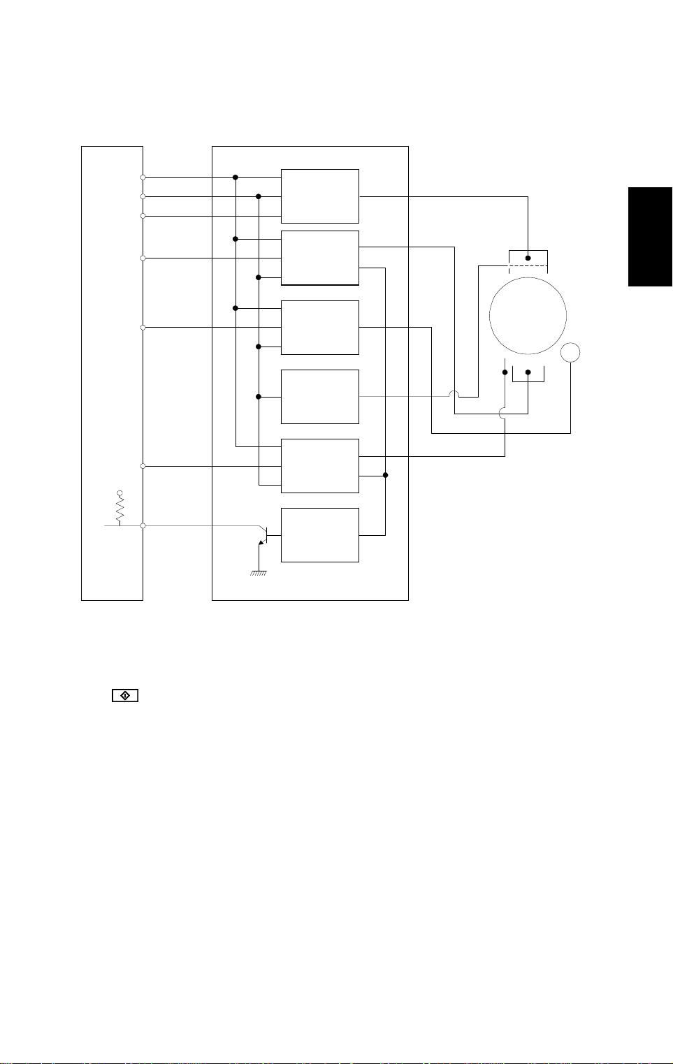
2.3 CHARGE CORONA CIRCUIT
Main Board High Voltage Supply Board
24 V
GND
C Trigger
CN102-7
CN102-6
CN102-5
DC/DC
Converter
T Trigger
B-PWM
S Trigger
4.7 k
5 V
CN102-4
CN102-3
CN102-2
CN102-1
DC/DC
Converter
DC/DC
Converter
Zener
Diode
DC/DC
Converter
Protection
Circuit
GC
Drum
B
S
T
A219D506.wmf
Detailed
Descriptions
The main board supplies +24 V to the high voltage supply board at CN102-7.
After the
key is pressed, the CPU drops CN102-5 from +24 V to 0 V.
This activates the charge corona circuit which applies a high negative voltage
of approximately –5 k volts to the charge corona wire. The corona wire then
generates a negative corona charge.
The grid plate limits the charge voltage to ensure that the charge does not
fluctuate and that an even charge is applied to the entire drum surface. The
grid plate is connected to ground through a zener diode in the high voltage
supply unit. The grid plate drains any charge in excess of –910 V, which is
discharged to ground through the zener diode.
2-5
Page 20

OPTICS 20 December 1996
3. OPTICS
3.1 OVERVIEW
[C][C] [A][B] [K] [E] [I] [G]
[D]
[F]
[H]
[J]
A219D507.wmf
During the copy cycle, an image of the original is reflected onto the drum
surface through the optics assembly as follows:
Light path:
Exposure Lamp [A] → Original → First Mirror [B] → Second Mirror [C] →
Third Mirror [D] → Lens [E] → Blue Filter [F] → Fourth Mirror [G] → Fifth
Mirror [H] → Sixth Mirror [I] → Drum [J]
This copier has eight standard reproduction ratios and a zoom function. The
operator can also change the reproduction ratio in one-percent steps from
50% to 200%. Stepper motors are used to change the positions of the lens
and 4th/5th mirrors to enlarge/reduce the image across the page. Changes in
reproduction ratio down the page are achieved by changing the scanner
speed.
The CPU monitors the temperature around the optics through a thermistor
which is located on the scanner frame. When the temperature reaches 40°C,
the optics cooling fan [K] starts rotating to draw cool air into the optics cavity.
The fan operates until the temperature drops below 38°C.
Additionally, a thermofuse on the 1st scanner provides back-up overheat
protection. It opens when the temperature reaches 128°C and cuts ac power
to the exposure lamp.
A blue filter is located just after the lens to improve the reproduction of red
areas of the original on copies.
2-6
Page 21
20 December 1996 OPTICS
3.2 SCANNER DRIVE
[H]
[F]
[D]
[C]
[A]
Detailed
Descriptions
[E]
[B]
A219D522.wmf
[G]
A stepper motor [A] is used to drive the scanners.
The first scanner [B], which consists of the exposure lamp and the first mirror,
is connected to the first scanner belt [C]. The second scanner [D], which
consists of the second and third mirrors, is connected to the second scanner
belt [E]. Both the scanners move along the guide rod [F].
There are no scanner drive wires, and only one side of the scanner is
supported (by a rod and guide rail). Therefore, the scanners should be
moved by moving the timing belt, and never by moving the scanners directly.
The pulley [G] drives both the first and second scanner belts. The 2nd
scanner moves at half the speed of the first scanner. This maintains the focal
distance between the original and the lens during scanning.
The scanner home position is detected by a home position sensor [H]. The
scanner return position is determined by counting the scanner motor drive
pulses.
2-7
Page 22
OPTICS 20 December 1996
3.3 LENS DRIVE
[A]
[C]
A219D509.wmf
[B]
: Reduction
: Enlargement
The lens motor [A] (stepper motor) changes the lens [B] position through the
timing belt [C] in accordance with the selected reproduction ratio to provide
the proper optical distance between the lens and the drum surface.
[D]
The rotation of the lens drive pulley moves the lens back and forth in discrete
steps. The home position of the lens is detected by a home position sensor
[D]. The main board keeps track of the lens position based on the number of
pulses sent to the lens motor.
2-8
Page 23
20 December 1996 OPTICS
3.4 4TH/5TH MIRROR DRIVE
[D]
[A]
[C]
[B]
A219D510.wmf
The 4th/5th mirror drive motor [A] (stepper motor) changes the 4th/5th mirror
assembly position through the pinion gears [B] and the rack gear [C] in
accordance with the selected reproduction ratio to provide the proper optical
distance between the lens and drum surface.
Detailed
Descriptions
The home position of the 4th/5th mirror assembly is detected by a home
position sensor [D]. The main board keeps track of the lens position based on
the number of pulses sent to the 4th/5th mirror motor.
2-9
Page 24
OPTICS 20 December 1996
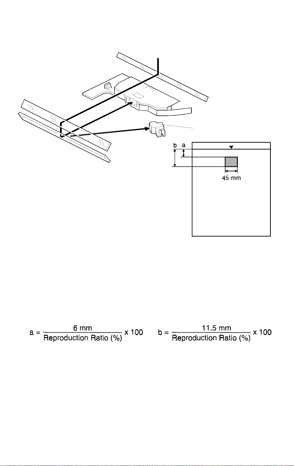
3.5 AUTOMATIC IMAGE DENSITY SENSOR
[A]
A219D511.wmf
A219D512.wmf
The auto ID sensor [A], a photodiode, is mounted on the upper front frame.
The sensor cover has a hole in it to allow light to fall directly onto the sensor.
Sampling starts 6 millimeters from the leading edge of the original and
continues for 11.5 millimeters from the leading edge of original in full size
mode. These lengths "a" and "b" will vary depending on the selected
reproduction ratio. The lengths "a" and "b" for each reproduction ratio are
calculated as follows:
Every original in ADS mode, the photosensor circuit converts the light
intensity to a voltage. The detected voltage is amplified and sent to the main
board. If less light is reflected from the original (the image is darker), the
sensor outputs a lower voltage. The CPU compares the maximum ADS
output voltage with the standard ADS reference voltage and compensates
the copy image density by changing the development bias voltage in
accordance with the difference. The standard ADS reference voltage (2.5 ±
0.1 V) is generated by SP 56. Details about changes to the development bias
voltage are explained in "Development Bias for Image Density Control".
2-10
Page 25

20 December 1996 OPTICS
3.6 EXPOSURE LAMP VOLTAGE CONTROL
The main board controls the exposure lamp voltage through the ac drive/dc
power supply board. The exposure lamp voltage is based on the base lamp
voltage and various correction factors. The method of control is different
depending on whether the image density is manually selected or the auto
image density mode is selected.
The exposure lamp voltage is determined by the following factors:
Lamp Voltage = Base Lamp Voltage Setting (SP48)
+
*Image Density Adjustment Factor (SP34)
+
*Manual Image Density Setting Factor
+
L
Correction 1 Factor (SP62)
V
+
L
V
Correction 2 Factor
+
Reproduction Ratio Correction Factor
*NOTE:
SP34 (Image Density Adjustment Factor) is applied for ADS mode
only.
The "Manual Image Density Factor" is applied for manual ID mode
only.
1) Base Lamp Voltage Setting
The lamp voltage is determined by the SP48 setting.
Detailed
Descriptions
Base Lamp Voltage = SP48 setting x 0.5 (120 V machines)
SP48 setting x 1.0 (230 V machines)
The default setting is: 140 = 70 V (120 V machines)
140 = 140 V (230 V machines)
The current lamp voltage (after all correction factors are included) can be
viewed with SP 51.
2-11
Page 26

OPTICS 20 December 1996
2) Image Density Adjustment Factor (SP34)
Depending on the SP34 setting, the development bias and the exposure
lamp settings are increased or decreased during ADS mode.
SP34 Setting Setting Dev. Bias Exposure Lamp
0Normal0 0
1 Light –40 V 0
2 Dark +40 V 0
3 Lightest –40 V +4 steps
4 Darkest +40 V –4 steps
1 step = 0.5 V (120 V machines) or 1.0 V (230 V machines)
3) Manual Image Density Setting Factor
Depending on the manual image density setting on the operation panel, the
exposure lamp voltage is changed as shown in the table below:
LighterDarker
Manual ID
Level
Exposure
Lamp Voltage
Factor
Development
Bias Voltage
(Volts)
1234567
V
– 6
0
steps
–200 –200 –200 –200 –200 –240 –240
V0 – 4
steps
V0 – 2
steps
V
0
V0 + 2
steps
0
: Base lamp voltage setting (SP48)
V
1 step = 0.5 V (120 V machines) or 1.0 V (230 V machines)
V0 + 6
steps
V0 + 12
steps
2-12
Page 27

20 December 1996 OPTICS
4) VL Correction 1 Factor
The light intensity may decrease because of dust accumulated on the optics
parts. Additionally, the drum sensitivity gradually decreases during the drum’s
life. This may cause dirty background on copies. To compensate for this, V
L
corrections 1 and 2 are done.
The exposure lamp voltage is increased by two steps at the set copy count
interval (a step is +2.0 V for 230 V machines, and +1 V for 120 V machines).
The table below shows the relationship between the SP setting and the
interval.
SP62 Setting VL Correction Interval
0 2 steps/8,000 copies
1 2 steps/6,000 copies
2 2 steps/4,000 copies
3 2 steps/2,000 copies
4 2 steps/1,000 copies
5 No correc t i on
(Default setting: 2)
Detailed
Descriptions
VL correction 1 compensates for the decrease of drum sensitivity and the
decrease in reflectivity of the 4th, 5th, and 6th mirrors due to dust.
L
5) V
Correction 2 Factor
L
V
correction 2 compensates for dust on the lens and mirrors 1 to 3, but is
independent of the drum condition.
The ADS sensor receives the light reflected through the 1st, 2nd and 3rd
mirrors from the white plate located under the middle part of the left scale.
The photosensor circuit converts this light intensity to a voltage, and the CPU
stores this in memory as the white plate reference voltage. This is done every
time SP56 (ADS reference voltage adjustment) is done, before sampling
starts for the ADS sensor adjustment.
Every 500 copies, the machine reads the intensity of light reflected from the
white plate and compares it with the white plate reference voltage.
If the measured voltage difference is more than 0.1 volt, +2 steps will be
L
added to the exposure lamp setting as the V
The sum of V
correction factors 1 and 2 cannot exceed +40 steps.
L
correction 2 factor.
correction factors 1 and 2 are automatically reset every time the light
V
L
intensity is adjusted with SP48. (SP56 must be done immediately after SP48;
see Service Remarks for details.)
2-13
Page 28

OPTICS 20 December 1996
6) Reproduction Ratio Correction Factor
The exposure lamp voltage is increased depending on the selected
magnification ratio in order to compensate for the change in concentration of
light on the drum.
Magnification Ratio Reproduction Ratio Correction Factor
50% to 61% +2 steps
62% to 119% 0
120% to 139% +2 steps
140% to 159% +4 steps
160% to 179% +8 steps
180% to 200% +12 steps
1 step = 0.5 V (120 V machines) or 1.0 V (230 V machines)
2-14
Page 29
20 December 1996 ERASE
4. ERASE
4.1 OVERVIEW
A219D513.wmf
bcdefghaijklm mlkj ihgfedcban
[A]
Detailed
Descriptions
A219D527.wmf
The erase lamp [A], which is installed in the copier main frame, consists of a
single row of white LEDs (38 LEDs) extended across the full width of the
drum. The erase lamp has the following functions: leading edge erase, side
erase and trail edge erase. (Trail edge erase begins after the trailing edge of
the copy paper; therefore, the trailing edge of the copy will not be erased.)
In side erase mode, the appropriate LEDs turn on in accordance with the
modes selected by the user.
2-15
Page 30

ERASE 20 December 1996
4.2 LEAD EDGE ERASE
The entire line of LEDs turn on when the main motor turns on. They stay on
until the erase margin slightly overlaps the lead edge of the original image
area on the drum (Lead Edge Erase Margin). This prevents the shadow of
the original edge from being developed on the copy. At this point, side erase
starts. The width of the leading erase margin can be adjusted using SP41.
4.3 SID E ERASE
Based on the combination of copy paper size and the reproduction ratio data,
the LEDs turn on in blocks (labeled "a" to "n" on the previous page). This
reduces drum cleaning load.
Also, to prevent horizontal black lines from appearing on the edge of copies
as a result of light leaking under the edge of the DF belt, the side erase
combination is changed between platen mode and DF mode; in DF mode,
more of the image is erased at the sides. (The setting of SP24 must be 0.)
-Platen Mode-
Blocks On Paper Size
None 99% to 200%
a to b 95% to 98%
a to c
a to d 88% to 91%
a to e
a to f 80% to 83%
a to g 75% to 79%
a to h
a to i
a to j 63% to 67%
a to k B5 59% to 62%
a to l 54% to 58%
a to m 50% to 53%
All (a to n)
11" x 17",
11" x 8
B4, B5
sideways
1/2
" x 11",
8
1/2
" x 5
8
A4
Lengthwise
Lead Edge and Trai l Edge
Erase
Reproduction
1/2
"
1/2
"
Ratio (%)
92% to 94%
84% to 87%
72% to 74%
68% to 71%
-DF Mode-
Blocks On Paper Size
None 99% to 200%
a to b 97% to 98%
a to c
a to d 90% to 92%
a to e
a to f 81% to 85%
a to g 77% to 80%
a to h
a to i
a to j 65% to 69%
a to k B5 61% to 64%
a to l 56% to 60%
a to m 50% to 55%
All (a to n)
11" x 17",
11" x 8
B4, B5
sideways
1/2
" x 11",
8
1/2
" x 5
8
A4
Lengthwise
Lead Edge and Trai l Edge
Erase
Reproduction
1/2
"
1/2
"
Ratio (%)
93% to 96%
86% to 89%
73% to 76%
70% to 72%
2-16
Page 31

20 December 1996 ERASE
4.4 TRAILING EDGE ERASE
This minimizes toner consumption.
The entire line of LEDs turns on when the drum has turned 9 mm at the end
of scanning (about 100 ms). The LEDs stay on to erase the leading edge of
the latent image in the next copy cycle. After the final copy, the erase lamps
turn off at the same time as the main motor.
Detailed
Descriptions
2-17
Page 32

DEVELOPMENT 20 December 1996
5. DEVELOPMENT
5.1 OVERVIEW
[D]
[C]
[A]
[E]
[B]
A219D514.wmf
When the main motor turns on, the development roller [A] and two agitators
[B] and [C] start turning.
There are permanent magnets in the development roller which attract the
developer particles (which are about 50 µm in diameter) to the roller. The
turning sleeve of the development roller carries the developer past the doctor
blade [D] which trims the developer to the desired thickness.
The development roller sleeve continues to turn, carrying the developer to the
drum [E]. When the developer brush contacts the drum surface, the
negatively charged areas of the drum surface attract and hold the positively
charged toner. In this way, the latent image is developed.
The development roller is given a suitable negative bias for preventing toner
from being attracted to the non-image areas on the drum which may have a
residual negative charge. The bias also controls image density.
2-18
Page 33

20 December 1996 DEVELOPMENT
5.2 DRIVE MECHANISM
[B]
[C]
[A]
A219D515.wmf
When the main motor [A] turns on, the drive is transmitted to the
development drive shaft [B] through gears and a timing belt. The rotation of
the development roller gear is transmitted to the agitator gears [C] through
other gears.
Detailed
Descriptions
2-19
Page 34

DEVELOPMENT 20 December 1996
5.3 CROSS-MIXING
[B]
[D]
[C]
[A]
A219D516.wmf
A cross-mixing mechanism is used to keep the toner and developer evenly
mixed. It also helps agitate the developer to prevent developer clumps from
forming and helps create the triboelectric charge.
Two agitators (helical coils) [A] and [B] are used for cross-mixing. The 1st
agitator [A] moves the developer from left to right. The toner supplied from
the cutout in the toner cartridge holder is mixed with the developer by the 1st
agitator. The 2nd agitator [B] rotates to move the developer back from right to
left. In this way, the developer is evenly distributed in the development unit.
The magnets in the development roller [C] attract the developer, and the
development roller sleeve rotates to carry the developer to the drum. The
doctor blade [D] trims the developer on the development roller to the desired
thickness.
2-20
Page 35

20 December 1996 DEVELOPMENT
5.4 DEVELOPMENT BIAS FOR IMAGE DENSITY CONTROL
The image density is controlled by changing two items: the amount of bias
voltage applied to the development roller sleeve, and the amount of voltage
applied to the exposure lamp.
Applying a bias voltage to the development sleeve reduces the potential
between the development roller and the drum, thereby reducing the amount
of toner transferred. As the bias voltage becomes greater, the copy becomes
lighter.
The method of control depends on whether the image density is manually
selected or auto image density is used.
The development bias voltage applied to the development roller sleeve has
the following factors:
Development bias voltage = Base Bias Voltage
(Manual or auto image density mode)
+
*Image Bias Adjustment Factor (SP33)
+
*Image Density Adjustment Factor (SP34)
+
R
Drum Residual Voltage (V
) Correction Factor
Detailed
Descriptions
*NOTE:
Image Bias Adjustment Factor (SP33) is applied for manual ID mode
only.
Image Density Adjustment Factor (SP34) is applied for ADS mode
only.
2-21
Page 36

DEVELOPMENT 20 December 1996
5.4.1 Base Bias Voltage Factor in Manual Image Density Mode
Manual ID
Level
Exposure
Lamp Voltage
Factor
Development
Bias Voltage
(Volts)
1234567
– 6
V
0
steps
–200 –200 –200 –200 –200 –240 –240
V0 – 4
steps
V0 – 2
steps
V
0
V0 + 2
steps
V
: Depends on th e set t i ng of SP48
0
V0 + 6
steps
LighterDarker
V0 + 12
steps
When manual ID level 6 or 7 is selected, –40 V is added to the base bias
voltage.
Using SP33 (Image Bias Adjustment), the base bias voltage can be
increased or decreased for all manual ID levels as follows:
SP Setting Setting Dev. Bias Note
0Normal0 Default
1 Darkest +40 V
2Darker+20 V
3 Light er –20 V
4 Lightest –40 V
2-22
Page 37

20 December 1996 DEVELOPMENT
5.4.2 Base Bias Voltage Factor in Automatic Image Density (ADS) Mode
The bias voltage for ADS mode depends on the background image density of
the original which is measured by the ADS sensor. (See "Automatic Image
Density Sensor" for more information about the ADS sensor.)
The CPU checks the voltage output from the automatic ID circuit. This circuit
has a peak hold function. The peak hold voltage is the maximum ADS sensor
output voltage, which corresponds to the maximum reflectivity of the original.
The CPU then determines the proper base bias level by comparing this
voltage (read from the original) with the standard ADS reference voltage.
The table below shows the relationship between the original background
density (ADS voltage ratio) and the base bias voltage.
Detailed
Descriptions
ADS Voltage Ratio [α] (%)
80 to 100 (light ) –200 V
75 to 79 –240 V
70 to 74 –280 V
60 to 69 –320 V
29 to 59 –360 V
0 to 28 (dark) –380 V
ADS Voltage Ratio [α]
ADS0
V
: Standard ADS Reference Voltage (2.5 ± 0.1 V)
Maximum ADS Output Voltage
=
Bias Voltage
ADS0
V
Using SP34, the base bias voltage and the exposure lamp setting can be
increased or decreased for the ADS mode as follows:
SP Setting Setting Dev. Bias Exposure Lamp
0Normal0 0
1 Light er –40 V 0
2Darker+40 V 0
3 Lightest –40 V +4 steps
4 Darkest +40 V –4 steps
(D efault Setting: 0)
5.4.3 Drum Residual Voltage (VR) Correction Factor
R
During the drum’s life, drum residual voltage (V
) will gradually increase. To
compensate for this, the bias voltage is increased by –20 V every 5 k copies.
The V
R
correction is done up to 20 k copies. The VR correction will not
change after 20 k copies.
2-23
Page 38

DEVELOPMENT 20 December 1996
5.5 DEVELOPMENT BIAS CIRCUIT
Main Board High Voltage Supply Board
24 V
GND
C Trigger
CN102-7
CN102-6
CN102-5
DC/DC
Converter
T Trigger
B-PWM
S Trigger
4.7 k
5 V
CN102-4
CN102-3
CN102-2
CN102-1
DC/DC
Converter
DC/DC
Converter
Zener
Diode
DC/DC
Converter
Protection
Circuit
GC
Drum
B
S
T
A219D506-2.wmf
The main board supplies +24 volts to the high voltage supply board from
CN102-7. When the
key is pressed, the CPU starts sending the bias
trigger pulses from CN102-3. This energizes the development bias circuit
within the high voltage supply board, which applies a high negative voltage to
the development roller. The development bias is applied whenever the drum
is rotating.
2-24
Page 39

20 December 1996 TONER SUPPLY
6. TONER SUPPLY
6.1 TONER BOTTLE REPLENISHMENT MECHANISM
[F]
[E]
[I]
[A]
[J]
[H]
[G]
Detailed
Descriptions
[D][C] [B]
A219D517.wmf
[K]
A219D518.wmf
When a toner bottle is placed on the bottle holder unit [A] and pushed back in
completely, the following happens automatically.
•
The pin [B] on the imaging unit toner shutter [C] is pushed out (shutter
opened) by the projection [D].
•
The pin [E] on the toner shutter [F] is pulled up (shutter opened) as a
result of the shape of the developer cartridge.
When the toner bottle holder lever [G] is pushed down to the operation
position, the following happens automatically to allow toner to be supplied to
the development unit.
•
The shaft [H] is pushed out from the machine by the curved rail behind
the toner bottle holder lever, and this pulls out the cap [I] into the chuck
[J], where it is held.
The toner end detection system determines when to drive the toner bottle
replenishment mechanism (see Toner End Detection). The toner supply
mechanism transports toner from the bottle to the development unit. The
toner bottle has a spiral groove [K] that helps move toner to the development
unit.
When the bottle holder unit is pulled out to add new toner, the following
happens automatically to prevent toner from scattering.
•
The chuck releases the toner bottle cap into its proper position.
•
Both shutters shut as a result of pressure from springs.
2-25
Page 40

TONER SUPPLY 20 December 199 6
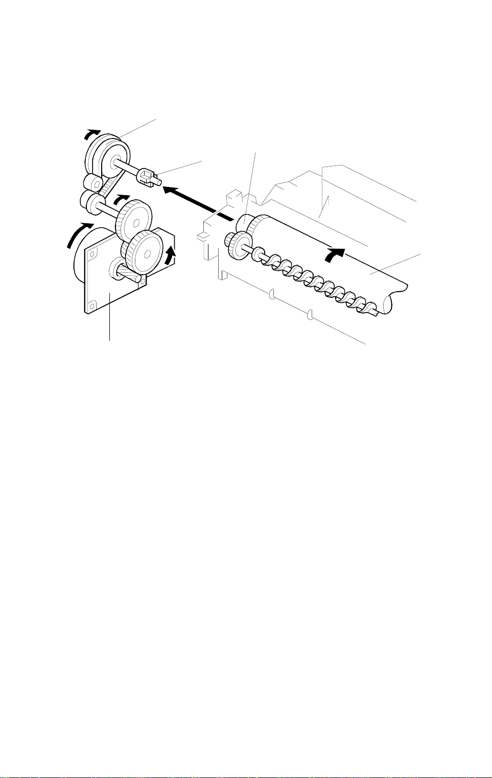
6.2 TONER SUPPLY MECHANISM
[A]
[B]
[E]
[C]
[F]
[D]
A219D519.wmf
The toner supply motor [A] drives the toner bottle [B] and the mylar blades
[C]. First, the toner falls down into the toner holder. The two toner supply
mylar blades transfer the toner to the opening [D], then the toner falls down
into the development unit.
There is a notch [E] on the toner bottle, and a roller [F] located under the
toner bottle. They both shake the toner bottle to prevent toner clumps from
forming. They also help to transport the toner inside the toner bottle when the
amount of toner inside is low.
2-26
Page 41

20 December 1996 TONER SUPPLY
6.3 TONER DENSITY DETECTION MECHANISM
[B]
[A]
Detailed
Descriptions
A219D516-2.wmf
A toner density sensor (TD sensor) [A] is used for toner density control.
The TD sensor is located under the 1st agitator [B]. The developer being
conveyed by the 1st agitator passes over the top of the sensor. As the toner
in the developer is consumed during development, the toner to carrier ratio
changes, resulting in a change in the magnetic permeability of the developer.
This in turn is converted to a corresponding voltage. The CPU monitors the
voltage to control the toner supply mechanism.
When new developer is installed, and SP66 (TD Sensor Initial Setting) is
done, the machine starts idling for developer initialization. During developer
initialization, the CPU adjusts the TD sensor control voltage so that the TD
sensor outputs 1.9 ± 0.1 V for the toner to carrier ratio of new developer
(4.0% by weight). This voltage is used as the standard TD sensor voltage.
2-27
Page 42

TONER SUPPLY 20 December 199 6
6.4 TD SENSOR CHECK AND TONER SUPPLY TIMING
(seconds)
Original Scan
Drum Charge
TD Sensor
2 s
Toner Supply Motor
The TD sensor voltage is monitored for two seconds when the 1st copy drum
charge starts. The CPU checks the voltage every 40 ms and stores the
second highest voltage of every 240 ms period. The stored voltages during
the two seconds are averaged, and then the average is used as the TD
sensor value for that detection period. The related amount of toner is added
by the toner supply motor (as described in Toner Supply Amount). The TD
sensor is monitored for two-second intervals is until the last original scan is
finished. Unlike a toner supply clutch mechanism, with a toner supply motor,
the copier can add toner during image development.
2 s
A219D540.wmf
2-28
Page 43

20 December 1996 TONER SUPPLY
6.5 TONER SUPPLY CONTROL
6.5.1 Modes Available
NOTE:
The following pages explain how the various settings control the
toner supply mechanism. They should not be adjusted in the field,
unless instructed to do so as a countermeasure for a specific
problem that may occur in the future.
SP30
Setting
0
1
2
3
4
Toner Supply
Mode
Detect Supply
Mode
Fixed Supply Mode None Fixed
Target Toner
Sensor Voltage
Depends on the
initial TD sensor
setting (1.9 ± 0.1
V).
Depends on SP53
(input manually).
Depends on the
initial TD sensor
setting (1.9 ± 0.1
V).
Depends on SP53
(input manually).
Toner Supply
Depends on the
TD sensor outp ut .
Depends on the
TD sensor outp ut .
Fixed
Fixed
Toner Near/End
Amount
Default setting: 0
Detection
Yes
Yes
No
No
No
Depending on the SP30 setting, Detect Supply mode or Fixed Supply mode
is selected. If 0, 1, 2, or 3 is selected with SP30, Detect Supply mode is used.
If 4 is selected, Fixed Supply mode is used.
Detailed
Descriptions
Note that when 2, 3, or 4 is selected, the machine will not perform the toner
near-end/end detection. Normally, SP30 should always be kept at the default
setting. The following pages describe the toner supply mode settings in detail.
6.5.2 Detect Supply Mode
In Detect Supply mode, the CPU monitors the TD sensor voltage, which
depends on the toner to carrier ratio in the developer. As the toner in the
developer is consumed, the TD sensor output voltage increases.
The TD sensor voltage is compared with the standard voltage (known as the
Target Toner Sensor Voltage), and toner is supplied when the TD sensor
output is higher than this target voltage.
The machine has two ways of calculating the target toner sensor voltage
(either the initial TD sensor setting is used, or a value can be input using
SP53); the method used depends on SP30. The toner supply amount can
also be changed using SP31 or 32.
2-29
Page 44

TONER SUPPLY 20 December 199 6
1) Target Toner Sensor Voltage
- Method 1 -
Normally (if 0 or 2 is selected with SP30) the voltage is determined by the
following factors:
Target Toner Sensor Voltage (V
) = Initial Developer Setting Voltage (VT0)
TS
+
Toner Density Adjustment Factor
a) Initial Developer Setting Voltage (V
T0
)
This voltage is adjusted to 1.9 ± 0.1 V during developer initialization
(refer to Toner Density Detection).
b) Toner Density Adjustment Factor
The target toner density can be changed by customers or service
engineers using SP mode 38 or user tool No. 6.
SP 38 Setting
0 0 Normal 0
1 1 Darker –S x 1/2
2 2 Lighter +S x 1/2
3Darkest–S
4 Lightest +S
User Tool 6
Setting
S: TD Sensor Sensitivity (SP36) De fa ul t : Nor m al
Toner Density
Toner Density
Adjustment Factor (β)
The sensor sensitivity is stored in SP36.
TD Sensor Sensitivity (S) [V/wt%] =
Change of TD sensor output [V]/Change of toner density [wt%] =
SP36 setting x 0.05 [V] (Default: SP36 = 15)
- Method 2 -
If 1 or 3 is selected with SP30, the setting of SP53 is used as the target toner
sensor voltage. In this case, the target toner sensor voltage is determined by
the following formula:
Target Toner Sensor Voltage = SP53 setting x 0.02 [V] (Default: 97 = 1.94 V)
The TD sensor initial setting is not changed by this SP mode. However, it is
ignored if method 2 is selected.
2-30
Page 45

20 December 1996 TONER SUPPLY
2) Toner Supply Amoun t
- Method 1 -
Normally (if 0 or 1 is selected with SP30), the toner supply amount is
determined by the difference between the actual TD sensor voltage (V
the target toner sensor voltage (V
). The following table shows the
TS
) and
T
relationship between the sensor output and the toner supply motor on time
for each copy.
Toner Supply Level TD Sensor Voltage Level [VT] Toner Supply Motor On Time
1
2
3
4
5
6 (Near End Level)
7 (Toner End Level)
V
< VT ≤ VTS + S/16
TS
V
+ S/16 < VT ≤ VTS + S/8
TS
V
+ S/8 < VT ≤ VTS + S/4
TS
V
+ S/4 < VT ≤ VTS + S/2
TS
V
+ S/2 < VT ≤ VTS + 4S/5
TS
V
≥ VTS + 4S/5
T
V
≥ VTS + S
T
The toner supply tim e unit "t" can be chang ed using SP31.
t = SP31 setting x 0.1 [secon d] (Def ault: 4 = 0.4 second)
S: TD Sensor Sensitivity (SP36)
* This value can be changed using SP35.
t
2 x t
4 x t
8 x t
16 x t
*10 seconds
*10 seconds
- Method 2 -
If 2 or 3 is selected with SP30, a fixed amount of toner is supplied when the
TD sensor voltage becomes higher than the target toner sensor voltage. The
amount of toner can be selected using SP32.
SP32 Setting
00.3 3.5
10.6 7
21.2 15
32.4 30
43.6 45
54.8 60
6
7 0 (No toner supply) 0
Toner Supply Motor O n Ti me
(seconds)
Stays on until the TD sensor
voltage becomes lower than the
target voltage.
Corresponding image area ratio
(%)
Detailed
Descriptions
2-31
Page 46

TONER SUPPLY 20 December 199 6
6.5.3 Fixed Supply Mode
If 4 is selected with SP30, the TD sensor is not used for toner supply control.
A fixed amount of toner is supplied every copy cycle. The toner supply
amount is determined by the SP32 setting.
6.5.4 Abnormal Condition in To ner D ensi t y D etection
If the output of the TD sensor goes below 0.2 volts (indicating far too much
toner), the CPU determines that the toner density supply is abnormal. The
CPU changes from the detect supply mode to the fixed supply mode. At the
same time, either the Auto ID indicator or the selected manual ID level starts
blinking, and the machine can be used. No SC code is generated. Under this
condition, the machine will not perform the toner end detection.
If the value recovers above 0.2 volts, or the main switch is turned off and on,
this condition is canceled and the toner density detection will recover to the
toner supply mode that was in use immediately before the abnormal condition
occurred.
2-32
Page 47

20 December 1996 TONER SUPPLY
6.6 TONER END
Toner Supply Level TD Sensor Voltage Level [VT] Toner Supply Motor On Time
1
2
3
4
5
6 (Near End Level)
7 (Toner End Level)
6.6.1 Toner Near End
V
< VT ≤ VTS + S/16
TS
V
+ S/16 < VT ≤ VTS + S/8
TS
V
+ S/8 < VT ≤ VTS + S/4
TS
V
+ S/4 < VT ≤ VTS + S/2
TS
V
+ S/2 < VT ≤ VTS + 4S/5
TS
V
≥ VTS + 4S/5
T
V
≥ VTS + S
T
The toner supply tim e unit "t" can be chang ed using SP31.
t = SP31 setting x 0.1 [secon d] (Def ault: 4 = 0.4 second)
S: TD Sensor Sensitivity (SP36)
* This value can be changed using SP35.
t
2 x t
4 x t
8 x t
16 x t
*10 seconds
*10 seconds
Detailed
Descriptions
If the CPU detects toner supply level 6 (V
≥ VTS + 4S/5) five times
T
consecutively, the toner end indicator blinks and the machine goes to the
toner near end condition.
In this condition, the toner supply motor is energized for 10 seconds for every
copy (this time can be changed using SP35). Also, the toner supply motor
stays on continuously between pages of a multi-copy job.
TS
If a toner sensor voltage lower than V
+ 4S/5 is detected twice
consecutively while the toner supply motor is on, the machine recovers from
the toner near end condition. Also, if this condition is detected during the
normal copy cycle, the toner near end is canceled.
6.6.2 Toner End
If toner supply level 6 is detected, the machine supplies toner between
copies and for 10 seconds after the copy job is finished (as explained above).
While the toner supply motor is on, if the CPU detects toner supply level 7
T
≥ VTS +S) three times consecutively, a toner end condition is detected
(V
and copier operation is disabled.
If the toner sensor voltage stays at level 6 after the toner near end condition
is detected, 50 more copies can be made. After 50 copies, the toner end
indicator lights and copying is disabled.
2-33
Page 48

TONER SUPPLY 20 December 199 6
6.6.3 Toner End Recovery
If the main switch is turned off and on, or the front door is opened and closed
during a toner end condition, the machine checks the toner bottle for
replacement. The main motor turns on and the toner supply motor is
intermittently energized. If the TD sensor voltage does not recover from level
7 within 40 seconds, the machine stops, keeping the toner end condition. If
TS
the TD sensor voltage becomes lower than V
+3S/5 in this period, the
machine recovers from the toner end condition. Then the toner supply motor
stops, but the main motor continuously rotates for 40 seconds to distribute
toner evenly inside the development unit.
2-34
Page 49

20 December 1996 IMAGE TRANSFER AND PAPER SEPARATION
7. IMAGE TRANSFER AND PAPER
SEPARATION
7.1 OVERALL
Detailed
Descriptions
[B]
[A]
A219D528.wmf
A high negative voltage (approximately –5 kV) is applied to the transfer
corona wire [A], and the corona wire generates negative ions. These
negative ions are applied to the back side of the copy paper. This negative
charge forces the paper against the drum and attracts the positively charged
toner onto the paper.
A high positive voltage (approximately +2.2 kV) is applied to the discharge
plate [B]. The negative charge on the copy paper is discharged after image
transfer by this discharge plate to ensure paper separation from the drum.
2-35
Page 50

IMAGE TRANSFER AND PAPER SEPARATION 20 December 1996
7.2 TRANSFER CORONA AND DISCHARGE PLATE CIRCUIT
Main Board High Voltage Supply Board
24 V
GND
C Trigger
CN102-7
CN102-6
CN102-5
DC/DC
Converter
T Trigger
B-PWM
S Trigger
4.7 k
5 V
CN102-4
CN102-3
CN102-2
CN102-1
DC/DC
Converter
DC/DC
Converter
Zener
Diode
DC/DC
Converter
Protection
Circuit
GC
Drum
B
S
T
A219D506-3.wmf
When the CPU drops CN102-4 from +24 V to 0 V, the transfer corona is
applied to the drum. When the CPU drops CN102-2 from 24 V to 0 V, a high
positive voltage (+2.2 kV) is applied to the discharge plate.
2-36
Page 51

20 December 1996 DRUM CLEANING
8. DRUM CLEANING
8.1 OVERVIEW
[A]
Detailed
Descriptions
A219D528-2.wmf
A counter blade system is used for drum cleaning. The cleaning blade [A]
scrapes off any toner remaining on the drum after the image is transferred to
the paper.
The removed toner is transported into the developer to be recycled.
2-37
Page 52

DRUM CLEANING 20 December 1996
8.2 TONER RECYCLING MECHANISM
[A]
[B]
A219D530.wmf
The toner removed from the drum falls onto the toner collection coil [A]. The
drum gear rotation is directly transmitted to the toner collection coil drive gear.
As the coil rotates, the toner moves from rear to front until it reaches the
toner recycling belt [B]. The paddles of the belt, which is driven by the toner
collection coil shaft, transports the toner into the developer, and the toner is
recycled.
2-38
Page 53

20 December 1996 QUENCHING
9. QUENCHING
[A]
Detailed
Descriptions
A219D513-2.wmf
In preparation for the next copy cycle, light from the quenching lamp (QL) [A],
which is installed in the upper unit, neutralizes any charge remaining on the
drum.
LEDs are used for quenching and the lamp is turned on whenever the main
motor rotates.
2-39
Page 54

PAPER FEED AND REGISTRATION 20 December 1996
10. PAPER FEED AND REGISTRATION
10.1 OVERVIEW
[B]
[C]
[D]
[E]
[A]
A219D500.wmf
This copier has one paper feed station and a by-pass feed table.
The paper feed station uses a paper tray [A] which can hold 500 sheets. The
by-pass feed table [B] can hold 80 sheets.
The paper tray uses two semicircular feed rollers [C] and a corner separator.
The semicircular feed rollers make one rotation to drive the top sheet of the
paper stack to the relay rollers [D]. The paper tray has two corner separators,
which allow only one sheet to feed. They also hold the paper stack. When the
paper tray is drawn out of the machine, the spring pressure is released, and
the tray bottom plate drops. In addition, there is no need to press the bottom
plate down when putting the tray back in.
The by-pass feed table uses a feed roller and friction pad system to feed the
top sheet of paper to the registration rollers.
In humid environments, copy paper may crease as it comes out of the fusing
unit. The optional tray heater [E] is available as a service part to keep copy
paper dry.
2-40
Page 55

20 December 1996 PAPER FEED AND REGISTRATION
10.2 PAPER TRAY FEED
10.2.1 Paper Lift Mechanism
[A]
[B]
[H]
[C]
[J]
[E]
[D]
A219D534.wmf
[I]
[G]
[F]
[K]
A219D535.wmf
The capacity of this tray is higher than usual for a corner separator type.
Because of this, there are two springs to lift the bottom plate.
As the tray is pushed into the machine, shutter [A] under the tray pushes
against projection [B]. As the shutter slides past the projection, the shutter
rotates, which forces the main lift spring [C] to pull the bottom plate lever [D].
The secondary lift spring [E] also pulls the bottom plate lever (this is
described below).
The tension applied to the main lift spring is always the same. However, the
secondary spring is only used when wider paper is installed, to lift the extra
weight of the paper stack. The tension applied to the secondary lift spring
depends on the paper width. Below a certain threshold width, tension is not
applied. Above this width, the wider the paper, the more tension is applied.
To apply spring tension for wider paper, projection [F] stops against the end
of rail [G]. When this happens, lever [H] swings out in the direction shown
above, which stretches the spring as the tray is pushed in. The side fence
position affects the orientation of [F]; wider paper causes [F] to contact [G]
earlier, leading to greater spring tension when the tray has been pushed all
the way in.
For narrow paper, the secondary lift spring is not needed. The side fence
orients projection [F] so that it slides past the rail as the tray is pushed into
the machine, and the spring stays slack.
Detailed
Descriptions
The bottom plate stopper [I] rests on the bottom plate [J]. It stops the bottom
plate at the maximum height. When the tray is getting empty, the corner
separators [K] start to rise, and continue to rise as the amount of paper in the
tray decreases, so that the paper is always at the correct height.
2-41
Page 56

PAPER FEED AND REGISTRATION 20 December 1996
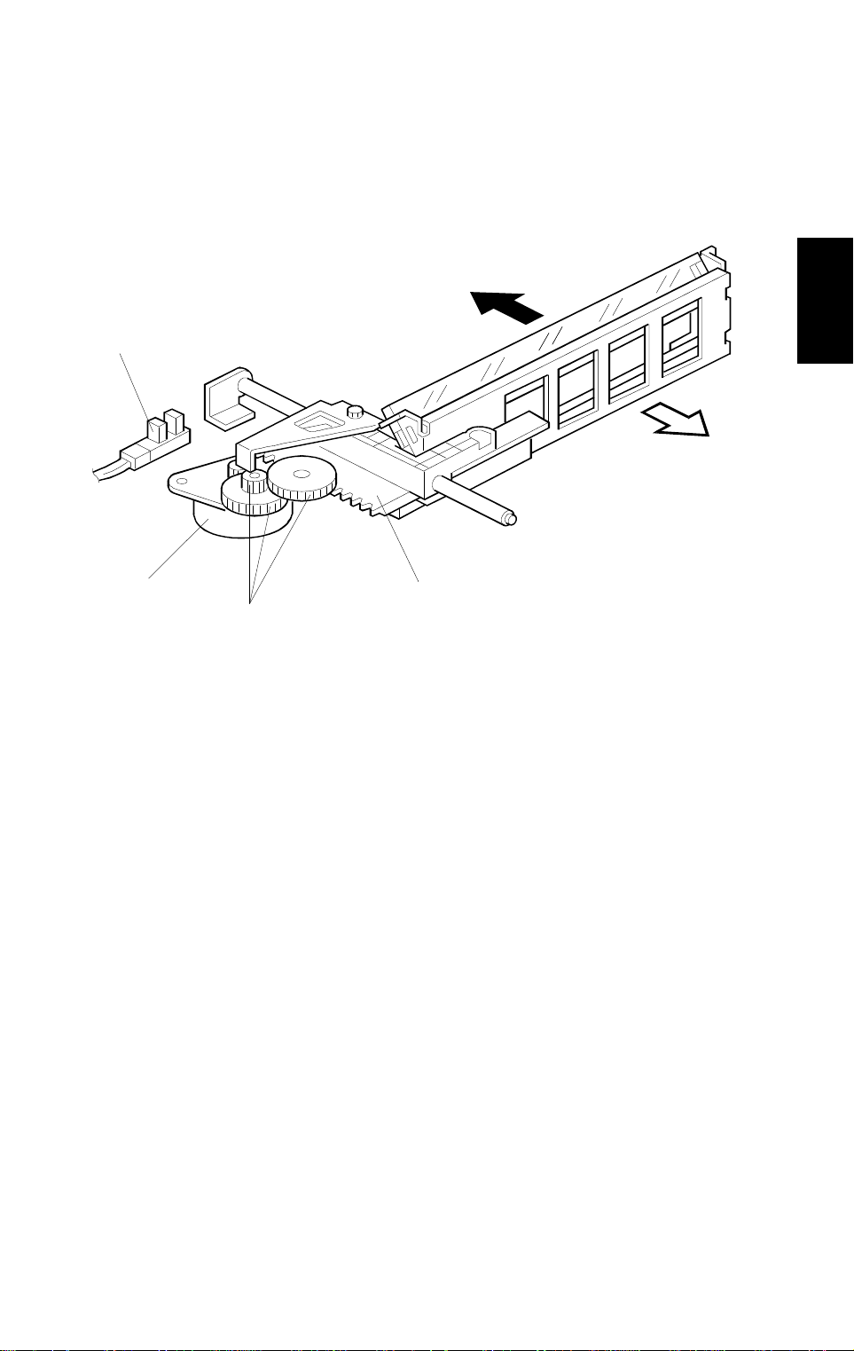
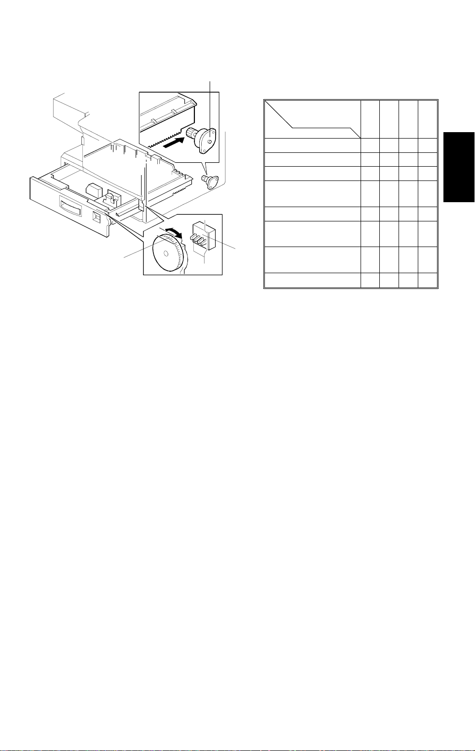
10.2.2 Paper Feed Mechanism
[E]
[D]
[A]
[C]
[B]
A219D508.wmf
[H]
[F]
[G]
A219D523.wmf
Through several gears and a timing belt, main motor rotation is transmitted to
the tray paper feed clutch gear [A] and the relay roller clutch gear [B].
-Feed rollers-
The tray paper feed clutch gear is on the same shaft as the semicircular
feed rollers [C]. After the
key is pressed, the tray paper feed clutch [D] is
energized for 250 milliseconds to release the stopper [E]. Then the drive of
the main motor is transmitted, and the feed rollers make one complete
rotation to feed the top sheet of paper which is enough for the leading edge
of the paper to be caught by the relay rollers [F]. The feed rollers stop when
the stopper drops back into the notch at the end of one complete turn.
-Relay rollers-
The relay roller clutch gear is on the same shaft as the relay rollers. The
rotation timing of the relay rollers is controlled by the relay roller clutch [G].
The CPU energizes the relay roller clutch after the
key is pressed (at the
same time as the tray paper feed clutch). Paper is fed from the relay rollers to
the registration rollers [H].
2-42
Page 57

20 December 1996 PAPER FEED AND REGISTRATION
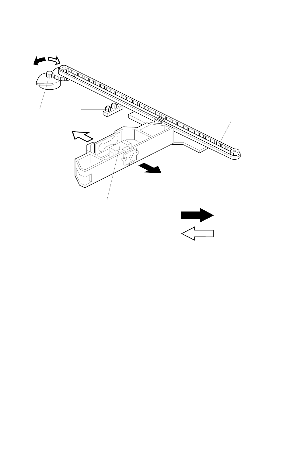
10.3 BY-PASS FEED
10.3.1 Overview
[A]
Detailed
Descriptions
A219D501.wmf
The by-pass feed table [A] can hold 80 sheets of paper.
This machine does not have a by-pass feed cover sensor. The by-pass feed
indicator is always displayed on the operation panel. The Add Paper indicator
will light when the user selects by-pass feed while the by-pass feed table is
closed or if there is no paper on the by-pass feed table.
After the
key is pressed, the cpu energizes the by-pass feed clutch and
the by-pass feed roller starts to feed paper to the registration roller.
This machine does not have any sensor or switch to determine the paper
size for by-pass feed. The machine will perform a full scan for all copies.
2-43
Page 58

PAPER FEED AND REGISTRATION 20 December 1996
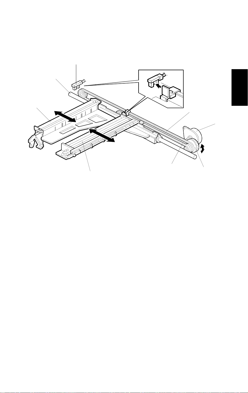
10.3.2 Paper Feed Mechanism and Paper End Detection
[A]
[C]
[D]
[B]
[F]
A219D524.wmf
[E]
A219D502.wmf
This machine uses a feed roller [A] and friction pad [B] mechanism, with drive
from the main motor [C] transmitted when the by-pass feed clutch [D] turns
on. The friction pad prevents all but the top sheet from feeding. Therefore,
during paper feed, the top sheet of paper is separated from the stack and fed
to the registration rollers.
Before placing paper on the by-pass feed table, the user must lower the
by-pass feed table by using the lever [E]. This is to ensure that the paper is
placed between the friction pad and the feed roller. Then, before starting to
copy, it must be put back up to move the paper stack into contact with the
feed roller.
When there is no paper on the by-pass feed table, the paper end feeler [F]
drops into the cutout in the by-pass feed table and the by-pass feed paper
end sensor is activated.
2-44
Page 59

20 December 1996 PAPER FEED AND REGISTRATION
10.4 PAPER REGISTRATION
[A]
[B]
[E][F]
[C]
[D]
A219D529.wmf
A219D523-2.wmf
Main motor rotation is transmitted to the registration roller clutch gear [A]
through several gears and a timing belt. When the registration clutch [B] is
energized, the rotation of the clutch gear is transmitted to the lower
registration roller [C].
Detailed
Descriptions
The registration sensor [D], which is positioned just before the registration
rollers, controls the relay roller clutch stop timing. The relay roller clutch stays
on for 130 milliseconds after the leading edge of the paper actuates the
registration sensor. The CPU then turns off the relay roller clutch. This delay
allows time for the paper to press against the registration rollers and buckle
slightly to correct skew.
The CPU energizes the registration clutch at the proper time to align the
paper with the image on the drum.
The registration sensor is also used for paper misfeed detection.
The paper dust mylar [E] on the upper registration roller [F] removes paper
dust before the paper reaches the transfer/separation unit.
2-45
Page 60

PAPER FEED AND REGISTRATION 20 December 1996
10.5 SIDE FENCE DOUBLE STOPPER MECHANISM
[B]
[A]
[A]
[B]
A219D503.wmf
There is a side fence stopper mechanism for both the front and rear side
fences.
If the tray is closed with excessive force after loading paper, paper may come
over the rear side fence, because the fence is deformed by the weight of the
paper leaning against it. As a result, skewing or paper jams may occur. To
prevent this, a side fence stopper mechanism has been added to the rear
side fence.
The release levers [A] each have a stopper which contains teeth like those
on a gear. The guide rails [B] also have teeth. When the release lever is
pushed, the gear teeth release each other and the side fences can be moved.
2-46
Page 61

20 December 1996 PAPER FEED AND REGISTRATION
10.6 PAPER END DETECTION
[B]
[D]
[A]
Detailed
[E]
Descriptions
[C]
A219D504.wmf
The paper end feeler [A] is on the same shaft as the paper end actuator [B].
When the paper tray runs out of paper, the paper end feeler drops into the
cutout [C] in the tray bottom plate. The paper end actuator activates the
paper end sensor [D].
The paper end actuator is in contact with the lever [E]. When the tray is
drawn out, the lever turns as shown by the arrow in the diagram. Then the
lever pushes up the actuator. As a result, the feeler rotates upwards. This
mechanism is necessary to prevent the feeler from getting damaged by the
paper tray body.
2-47
Page 62

PAPER FEED AND REGISTRATION 20 December 1996
10.7 PAPER FEED AND MISFEED DETECTION TIMING
Start Key
Main Motor
Tray Paper Feed Clutch
Relay Roller Clutch
Registration Clutch
Registration Sensor
Exit Sensor
0
A4 sideways
0.10 0.35
0.13
,
2.09
2.01
(1)
4.97
,
(2)
(second)
7.45
,
(3)
7.80
,
(4)
A219D526.wmf
The registration sensor and the exit sensor are used for misfeed detection. If
the CPU detects a misfeed, the Check Paper Path and the Location
indicators turn on.
Just after the main switch is turned on, the CPU checks these sensors for
any jammed paper.
During the copy cycle, the CPU performs four kinds of misfeed detection. The
following explains jam detection timing for copying A4 sideways paper.
,
(1): Checks whether the registration sensor is actuated within 2.01 seconds
after the
,
(2): Checks whether the exit sensor is actuated within 4.97 seconds after
the
,
(3): Checks whether the copy paper has passed through the registration
sensor 7.45 seconds after the
,
(4): Checks whether the copy paper has passed through the exit sensor
7.80 seconds after the
NOTE:
,
,
The detection timing for
key is pressed.
key is pressed.
key is pressed.
key is pressed.
(1) and , (2) are detected from the lead edge of the copy paper.
(3) and , (4) are detected from the trail edge of the copy paper.
,
(3) and , (4) will vary with the
copy paper size in use.
2-48
Page 63
20 December 1996 PAPER FEED AND REGISTRATION
10.8 OTHERS
[C]
SW
(from right to left)
Size
1/2
1/2
1/2
"x13" )
"x14"
"
[B]
A219D525.wmf
A3, F( 8
A4 Lengthwise
A4 Sideways
A5 Sideways,
11"x17"
B4, 8
B5 Sideways,
1/2
8
[A]
●: ON (Not pushed ) ❍: OFF (Pushed)
"x11"
B5 Lengthwise,
11"x8
* (Asterisk)
10.8.1 Paper Size Detection
There are four microswitches [A] on the front right plate of the main frame.
The sensors are actuated by a paper size actuator [B] behind the paper size
indicator plate on the front right of the tray. Each paper size has its own
actuator, with a unique combination of notches. To determine which size tray
has been installed, the cpu reads which switches have been pressed. The
cpu disables paper feed if the paper size cannot be detected. If the paper
size actuator is broken, or if there is no tray, the Add Paper indicator will light.
1234
●●●❍
●❍●❍
●●❍❍
●❍❍❍
❍●❍❍
❍❍❍❍
❍❍●❍
❍❍●●
Detailed
Descriptions
When the paper size actuator is at the "*" mark, the paper tray can be set up
to accommodate one of a wider range of paper sizes. The setting for this
mode is performed with SP74. Paper length will be taken from this setting,
and not from the registration sensor readings.
Because of the limited space on the operation panel, not all the paper sizes
possible with the paper size actuator can be displayed on the operation
panel. In some cases, the " * " mark will be displayed, but the machine will
operate in accordance with the selected paper size.
The paper size switch also acts as a tray open sensor.
10.8.2 Shock Absorber
At the position shown, a damper [C] is installed to reduce the shock to the
paper tray when it is pushed back into the copier. This is to prevent the stack
of paper inside the paper tray from coming over the corner separators, which
will cause double feeding or image skew on copies.
2-49
Page 64

IMAGE FUSING 20 December 1996
11. IMAGE FUSING
11.1 OVERVIEW
[A]
[E]
[B]
[D]
[F]
[C]
A219D531.wmf
[G]
A219D539.wmf
After the image is transferred, the copy paper enters the fusing unit. The
image is fused to the copy paper by heat and pressure using a hot roller [A]
and a pressure roller [B].
The CPU monitors the hot roller temperature through a thermistor [C] which
is in contact with the hot roller surface. A thermofuse [D] prevents the fusing
unit from overheating.
The hot roller strippers [E] separate the copy paper from the hot roller and
direct it to the exit rollers. The exit sensor [F] monitors the progress of the
copy paper through the fusing unit and acts as a misfeed detector. The exit
rollers [G] drive the copy paper to the copy tray.
2-50
Page 65

20 December 1996 IMAGE FUSING
11.2 FUSING DRIVE MECHANISM
[B]
[A]
[D]
A219D539-2.wmf
[E]
[C]
Detailed
Descriptions
[F]
[G]
A219D532.wmf
Drive from the main motor [A] is transmitted to the hot roller [B] through idle
gears and a timing belt. The hot roller always rotates while the main motor
rotates.
The fusing unit drive release mechanism automatically disengages the fusing
drive gear [C] when the front cover [D] is opened. This allows the fusing unit
drive gear to rotate freely so that misfed paper can be easily removed.
When the front cover is opened, the actuator plate [E] pulls the release wire
[F]. The wire pulls the fusing unit gear bracket [G] and the fusing unit drive is
disengaged.
2-51
Page 66

IMAGE FUSING 20 December 1996
11.3 FUSING LAMP CONTROL
The CPU monitors the temperature of the hot roller surface using a
thermistor. The fusing lamp is turned on and off to keep the hot roller surface
at the target temperature. The target temperature depends on the machine
condition as follows:
Machine Condition
Ready
After the main switch is turned
on, until one minut e has passed
since the fusing temperature
reached the R eady condition.
After the above time period, the
copier enters the energy saver
mode.
During copying
Fusing Lamp ON/ O FF
Threshold
165°C: 120 V machines
172°C: 230 V machines
190°C
120°C: 120 V machines
130°C: 230 V machines
190°C
A219D533.wmf
Remarks
—
After the fusing temperature
reaches the read y temperature,
the fusing lam p i s kept on until
it reaches 190°C.
When the key is pressed,
the red indicator blinks and
copying starts after the fusing
temperature reaches the Ready
condition.
—
2-52
Page 67

20 December 1996 IMAGE FUSING
When the main switch is turned on, the CPU turns on the fusing lamp. When
the fusing thermistor detects the ready temperature, the machine enters the
ready condition. After the ready temperature is detected, the CPU keeps the
fusing temperature at 190°C for one minute, then the target temperature is
changed to 120°C (120 V machines) or 130° C (230 V machines).
When the
key is pressed, if the fusing lamp temperature is higher than
the ready temperature, the machine starts copying immediately. If the
temperature is lower, the fusing lamp is turned on and the start indicator turns
red and blinks. Copying starts after the fusing temperature reaches the ready
temperature, and the fusing temperature is kept at 190ÉC during copying.
After copying is finished, the fusing temperature is kept at 190°C for one
minute.
To prevent any copy quality problem caused by exposure lamp intensity
fluctuation, the fusing lamp does not turn on while the exposure lamp is on,
even if the fusing temperature drops below 190°C.
Detailed
Descriptions
2-53
Page 68

IMAGE FUSING 20 December 1996
11.4 FUSING LAMP CONTROL CIRCUIT
11.4.1 Overview
CN113-1
Trigger Pulse
24 V
0 V
Main Board
CN113-2
5 V
CN101-3
24 V
CN101-4
CN207-7
CN207-6
FU1
T202
AC Power Source
T201
PC2
T208
✽
C20
✽
L4
RY1
T207
T205
T206
T204
T203
AC Drive/DC Power
Supply Board
Fusing
Thermistor
Fusing Lamp
Main Switch
Interlock
Switch
✽
230 V machines only
A219D537.wmf
The main board monitors the fusing temperature through a thermistor. It uses
the zero cross signal generated by the ac drive/dc power supply board to
control the applied power accurately.
Normally, the voltage applied to the lamp is the full duty cycle of the ac
waveform. However, through SP29, fusing power can be set to phase control
mode. (Phase control is used only if the customer has a problem with
electrical noise or interference.)
2-54
Page 69

20 December 1996 IMAGE FUSING
11.4.2 On/Off Control
When the main switch is turned on, the main board starts to output a trigger
pulse, which has the same timing as the zero cross signal, to the ac drive/dc
power supply board. This trigger pulse allows maximum ac power to be
applied to the fusing lamp. When the operating temperature is reached, the
CPU stops outputting the trigger pulse (the trigger stays HIGH) and the fusing
lamp turns off.
11.4.3 Phase Control Mode
Detailed
Descriptions
A219D538.wmf
The main board sends the fusing lamp trigger pulse (LOW active) to the ac
drive/dc power supply board, which provides ac power to the fusing lamp at
the falling edge of each trigger pulse. The trigger pulse goes HIGH when the
main board receives the zero cross signal.
The amount of time that power is applied to the fusing lamp depends on the
temperature of the hot roller.
The trigger pulse (LOW part) is wider [C1] and power is supplied for longer
[D1] when the hot roller temperature is lower. It is narrower [C2] and power is
supplied for a shorter time [D2] when the hot roller is near the operating
temperature.
2-55
Page 70

IMAGE FUSING 20 December 1996
11.4.4 Overheat Protection
There is an overheat protection circuit in the main board. If the hot roller
temperature reaches 245°C during the main motor off condition, or 255°C
during the main motor on condition, the resistance of the thermistor (between
CN113-1 and CN113-2) becomes too low. If the main board detects this
condition, "E-53" lights on the operation panel and power to the fusing lamp
is cut.
Even if the thermistor overheat protection fails, the thermofuse opens when it
reaches 169°C, removing power from the fusing lamp.
2-56
Page 71

SECTION 3
INSTALLATION
Page 72

20 December 1996 INSTALLATION REQUIR EM ENTS
1. INSTALLATION REQUIREMENTS
1.1 ENVIRONMENT
1. Temperature Range: 10°C to 30°C (50°F to 87°F)
2. Humidity Range: 15% to 90% RH
3. Ambient Illumination: Less than 1,500 lux (Do not exposure to direct
sunlight.)
4. Ventilation: Room air should turn over at least 3 times per
hour
3
5. Ambient Dust: Less than 0.15 mg/m
(4 x 10⁻³ oz/yd3)
6. If the place of installation is air-conditioned or heated, do not place the
machine:
1) Where it will not be subjected to sudden temperature changes.
2) Where it will not be directly exposed to cool air from an air-conditioner.
3) Where it will not be directly exposed to heat from a heater.
7. Do not place the machine where it will be exposed to corrosive gasses.
8. Do not install the machine at any location over 2,000 m (6,500 feet)
above sea level.
9. Place the copier on a strong and level base.
10. Do not place the machine where it may be subjected to strong vibrations.
1.2 MACHINE LEVEL
1. Front to back: Within 5 mm (0.2") of level
Installation
2. Right to left: Within 5 mm (0.2") of level
3-1
Page 73

INSTALLATION REQUIREMENTS 20 December 1996
1.3 MINIMUM SPACE REQUIREMENTS
Place the copier near the power source, providing clearance as shown:
More than 10 cm, 4.0"
More than
20 cm, 7.9"
More than 70 cm, 27.6"
1.4 POWER REQUIREME NTS
More than
21 cm, 8.1"
A219I506.wmf
CAUTION
1. Make sure the plug is firmly inserted in the outlet.
2. Avoid mult i- wiring.
3. Do not set anything on the power cord.
1. Input voltage level: 110 ~ 127 V/60 Hz: More than 15 A
220 ~ 240 V/50/60 Hz: More than 8 A
2. Permissible voltage
10%
fluctuation:
3-2
Page 74

20 December 1996 COPIER (A219)
2. COPIER (A219)
2.1 ACCESSORY CHECK
Check the quantity and condition of the accessories in the box against the
following list:
1. Model Name Decal (-10, -22 machines)
2. Symbol Explanation Decal - Multi-language
3. Installation Procedure - Multi-language (-10, -15, -22, -26 machines)
4. Operation Instructions - English (-10, -15, -17, -19, -22, -26, -29
machines)
5. NECR - English (-17 machines)
6. NECR - Multi-language (-27, -29 machines)
7. Copy Tray
8. User Survey Card (-17 machines)
9. Envelope for NECR (-17 machines)
Installation
3-3
Page 75

COPIER (A219) 20 December 1996
2.2 INSTALLATION PROCEDURE
[B]
[A]
A219I500.wmf
[C]
[E]
A219I501.wmf
CAUTION
Do not plug in the power cord before starting the following procedure.
1. Remove all strips of tape shown above.
2. Pull out the paper tray [A], and remove the cardboard [B].
[D]
3. Open the front cover and raise the toner bottle holder lever [C].
Then pull down the securing lever [D], and remove the toner bottle holder
[E].
3-4
Page 76

20 December 1996 COPIER (A219)
[B]
[F]
[C]
[E]
[D]
[A]
Installation
A219I502.wmf
[G]
A219I503.wmf
4. Turn the "B1" lever [A] counterclockwise to lower the transfer corona unit.
5. Remove the knob screw [B] and gently pull out the imaging unit [C].
Then place it on a clean sheet of paper.
6. Remove the cover [D] from the imaging unit (1 screw and 1 snap [E]).
7. Pour in the developer [F] evenly into the imaging unit. Then rotate the
outer gear [G] for one or two turns to distribute the developer as shown.
NOTE:
When installing new developer or manually rotating the
development roller, always make sure to turn the gear in the
direction shown above. Also do not rotate the gear more than 3
turns to prevent damage to the unit.
8. Remount the cover on the imaging unit, and install the unit in the copier
(1 knob screw). Then turn the "B1" lever clockwise to raise the transfer
corona unit.
3-5
Page 77

COPIER (A219) 20 December 1996
[B]
[D]
[F]
[C]
[H]
[G]
[A]
[E]
A219I504.wmf
9. Install the toner bottle holder [A] in the copier as shown.
10. Shake the toner bottle [B] well.
NOTE:
Do not remove the bottle cap [C] of the toner bottle at this time.
11. Unscrew the bottle cap and insert the toner bottle into the holder, so that
the rib [D] rides the rail [E].
NOTE:
Do not open the inner bottle cap [F].
12. Reposition the holder by making sure that the securing lever [G] clicks.
Then press down the holder lever [H] to secure the bottle. Close the front
cover.
3-6
Page 78
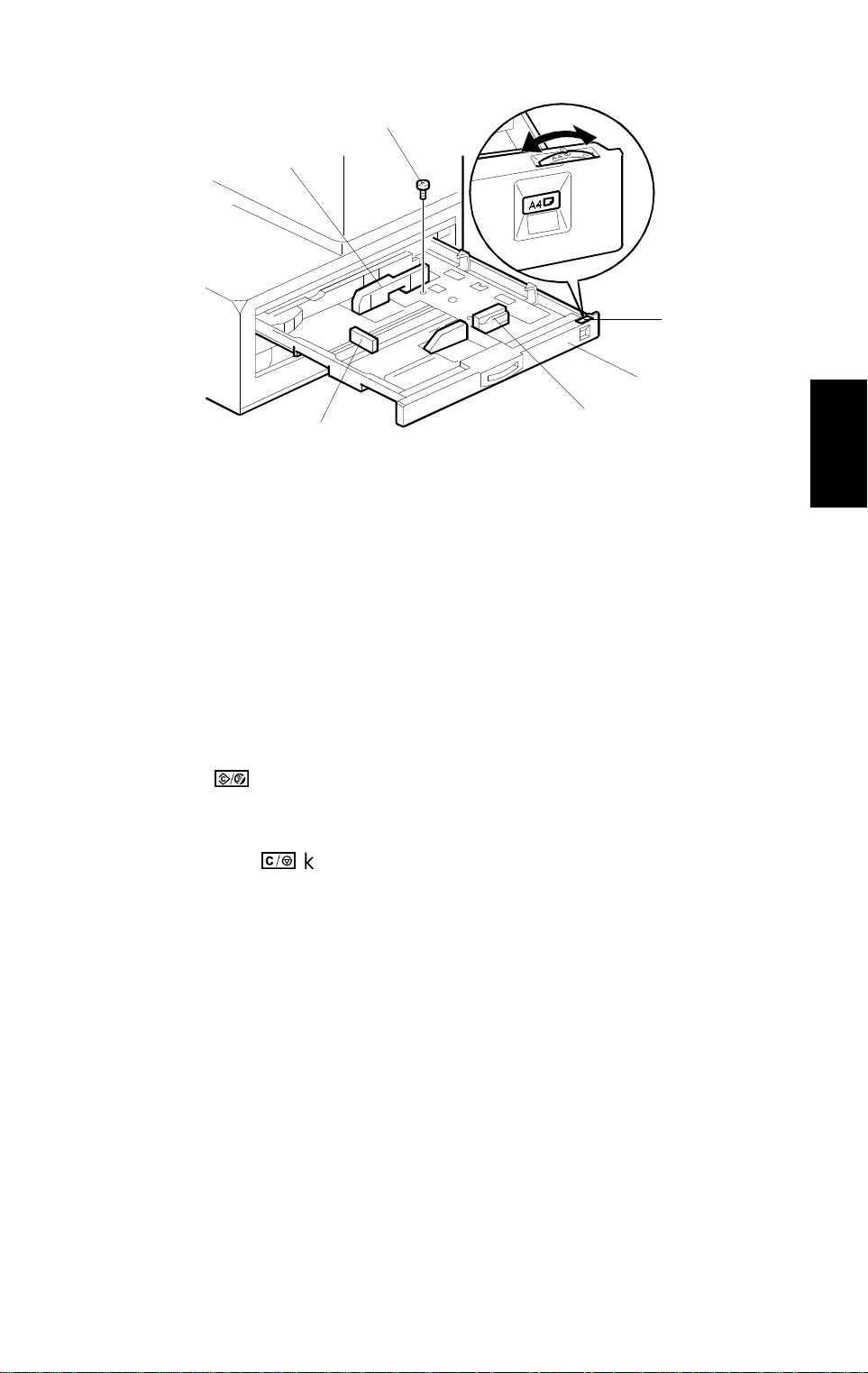
20 December 1996 COPIER (A219)
[E]
[C]
[B]
[A]
[C]
[D]
A219I505.wmf
13. Pull the paper tray [A] out and turn the paper size dial [B] to select the
appropriate size. Adjust the side guides [C] and the end guide [D] to
match the paper size.
NOTE:
1) Make sure the stack of paper is aligned, and that there is no
space between the side guides and the paper stack.
Installation
2) Always push the paper tray in gently.
14. Plug in the copier and turn on the main switch. Wait until it warms up. (It
takes about 45 seconds.)
15. Enter the SP mode as follows:
1) Press the
key.
2) Enter "107" using the numeric keys.
3) Hold down the
key for more than 3 seconds.
16. Perform the TD sensor initial setting as follows:
1) Enter "66" using the numeric keys.
2) Press the "Auto Image Density" key.
NOTE:
The machine will automatically stop when completed. (It takes
about 1 minute.)
17. Turn the main switch off and on to exit SP mode.
18. Check the copy quality and machine operation.
19. Inform the customer of the notes in step 13 concerning the paper tray.
Also find out if the customer changes paper sizes frequently. If not, inform
the customer that the side guides can be fixed with a screw [E] to achieve
better paper feed quality (use tapping screw M3 x 8).
3-7
Page 79

DOCUMENT FEEDER (A 662) 20 December 1996
3. DOCUMENT FEEDER (A662)
3.1 ACCESSORY CHECK
Check the accessories against the following list:
Description Q’ty
1. Voltage Reference Decal.................................................. 1
2. Thumb Screw M4 x 12...................................................... 2
3. Stud Screw (M3)............................................................... 2
4. Installation Procedure - English........................................ 1
5. NECR - Multi-language..................................................... 1
6. Interface Unit for A219 copier .......................................... 1
7. Accessory Kit for A203 copier .......................................... 1
Interface Unit Bracket.................................................. 1
•
Stud Screw (M4).......................................................... 2
•
Harness Clamp ........................................................... 1
•
Upper Unit Stand...... .................. ................................. 1
•
Stepped Screw (Short)................................................ 1
•
Stepped Screw (Long)................................................. 1
•
Magnet......................................................................... 1
•
Operation Decal .......................................................... 1
•
Screw Driver................................................................ 1
•
3-8
Page 80

20 December 1996 DOCUMENT FEEDER (A662)
3.2 INSTALLATION PROCEDURE
[B]
[A]
[F] 230 ~ 240 V
[C]
[D] 220 ~ 230 V
[E]
A662I500.wmf
Installation
CAUTION
When installing the DF, make sure the copier is unplugged.
1. Remove the platen cover [A] from the copier.
2. Replace the 2 screws with the 2 stud screws [B].
Use the M3 stud screws for A219.
•
Use the M4 stud screws for A203.
•
3. Remove the strips of tape from the DF.
CAUTION
The next step (step 4) must be done only in 240 volt areas.
4. Perform the conversion from 220 ∼ 230 V to 240 V as follows:
1) Remove the main board cover [C] (2 screws).
2) Disconnect the connector for 220 ∼ 230 V [D] (Black Wire) from the ac
harness connector [E] and connect the connector for 240 V [F] (White
Wire) to the ac harness connector.
A662I501.img
3) Reinstall the cover.
3-9
Page 81

DOCUMENT FEEDER (A 662) 20 December 1996
[A]
[C]
[B]
A662I502.img
[F]
[E]
A662I503.wmf
[G]
[J]
[H]
[I]
A662I504.wmf
5. Insert the DF [A] into the holes [B] in the copier upper cover.
6. Secure the DF to the copier (2 thumb screws [C]).
7. Remove the rear cover [D] (2 screws) and cut away the portion [E] with
cutting pliers as shown.
8. Locate the 4P connector [F] and connect it to the ADF interface board
[G], then secure the DF interface unit [H] to the copier (1 screw).
[D]
9. Plug the connector [I] (3P) in to CN202 on the ac drive dc power supply
board [J].
3-10
Page 82

20 December 1996 DOCUMENT FEEDER (A662)
[C]
[A]
[B]
A662I505.wmf
[E]
[F]
[D]
A662I514.img
Installation
[F]
A662I515.img
10. Reinstall the rear cover.
11. Plug the optics fiber cable [A] into the DF and the copier.
12. Plug the power supply cord [B] of the DF into the outlet in the copier rear
cover.
13. Attatch the voltage reference decal [C].
14. Check that the rubber pad [D] is in contact with the top of the operation
panel cover. If it is not, remove the DF grip [E] (2 screws), then adjust the
position of the magnet catch [F] so that the rubber pad is in contact with
the top of the operation panel cover.
15. Turn on the main switch and check the operation of the DF.
3-11
Page 83

SORTER (A657) 20 December 1996
4. SORTER (A657)
4.1 ACCESSORY CHECK
Check the accessories against the following list:
Description Q’ty
1. Holder Bracket.................................................................. 1
2. Magnet Catch ................................................................... 1
3. Tapping Screw M4 x 6...................................................... 6
4. Grounding Screw M4 x 8.................................................. 1
5. Snap Ring......................................................................... 1
6. NECR - Multi-language..................................................... 1
7. Installation Procedure - English........................................ 1
3-12
Page 84

20 December 1996 SORTER (A657)
4.2 INSTALLATION PROCEDURE
[A]
[C]
[B]
NOTE:
A657I500.wmf
[E]
[D]
[D]
A657I501.wmf
1) Keep the shipping retainers after installing the machine. They will
be reused if the machine will be transported to an another location
in the future.
2) Proper installation of the shipping retainers is required in order to
avoid any transport damage.
Installation
3) Do not grasp the sorter by the top cover and stay as shown by [A].
Hold both sides of the sorter as shown by [B]. This is to prevent
damage to the anti-static brush [C].
CAUTION
Unplug the copier power cord before star ting the follo wing procedure.
1. Remove the copy tray from the copier.
2. Remove the strips of tape [D] and styrofoam blocks [E].
3-13
Page 85

SORTER (A657) 20 December 1996
[A]
[B]
[D]
A657I502.wmf
[C]
A657I503.wmf
3. Remove the 2 portions [A] on the left hand side of the copier with cutting
pliers as shown.
4. Remove the rear cover [B] (2 screws).
5. Mount the sorter holder bracket [C] on the copier frame (3 tapping
screws).
6. Mount the magnetic catch [D] near the exit cover (2 tapping screws).
3-14
Page 86

20 December 1996 SORTER (A657)
[B]
[E]
[C]
[D]
[F]
[G]
[A]
A657I504.wmf
Installation
7. Install the sorter [A] on the sorter holder bracket [B] (1 snap ring) as
shown.
8. Insert the sorter harness [C] and the grounding wire [D] through the
opening in the lower left cover. Plug the connector in to CN130 [E] on the
main control board, and secure the grounding wire to the copier frame [F]
(1 M4 x 8 sc rew).
9. Secure the bracket [G] (1 tapping screw).
10. Reinstall the rear cover.
11. Plug in the copier power cord and turn on the main switch.
12. Enter SP mode as follows:
1) Press the
2) Enter "107" using the numeric keys.
3) Hold down the
13. Press the following sequence of keys to change the "SP 71" value to "1".
→ 3 →
9
key.
key for more than 3 seconds.
→ 3 →
14. Turn the main switch off and on.
15. Check the sorter’s operation.
3-15
Page 87

OTHERS 20 December 1996
5. OTHERS
5.1 OPTICS ANTI-CONDENSATION HEATER INSTALLATION
(OPTION)
[E]
[B]
[A]
[C]
[D]
A219I507.wmf
NOTE:
Unplug the copier power cord before star ting the follo wing procedure.
1. Remove the rear cover. (See "Replacement and Adjustment - Exterior
2. Remove the exposure glass. (See "Replacement and Adjustment -
3. By using the timing belt [A], manually move the 1st and 2nd scanner units
The optics anti-condensation heater keeps water from condensing
on the copier’s mirrors.
Such condensation occurs at cold temperatures with high humidity,
and causes the first few copies of the day to be dark, or even black.
The heater is available as a service part. (See the parts catalog.)
CAUTION
Cover Removal".)
Exposure Glass Removal".)
away from the home position.
NOTE:
Move the scanners by using the timing belt as shown in the
diagram. Do not handle the scanners directly.
3-16
Page 88

20 December 1996 OTHERS
4. Pass the connector [B] through the opening [C], and mount the
anit-condensation heater [D] as shown (1 screw).
5. Connect the red two-pin connector [E] at the rear of the copier to the
heater’s connector [B] (red).
6. Make sure that scanner drive belt and mirrors do not touch the heater
harness while they are functioning.
NOTE:
Tell the customer that even when the copier main switch is turned
off, the copier power cord should be plugged in. Otherwise, the
optics anti-condensation heater will not function.
Installation
3-17
Page 89

OTHERS 20 December 1996
5.2 TRAY HEATER INSTALLATION (OPTION)
NOTE:
[H]
[G]
[F]
[E]
[C]
[B]
[A]
[D]
A219I508.wmf
The optional tray heater keeps copy paper dry. In humid
environments, copy paper may crease as it comes out of the fusing
unit. The heater is available as a service part. (See the parts catalog.)
CAUTION
Unplug the copier power cord before star ting the follo wing procedure.
1. Remove the paper tray. (See "Replacement and Adjustment - Paper Tray
Removal".)
2. Connect the interface harness [A] to the tray heater [B]. Then mount the
heater on the heater bracket [C] as shown (1 screw).
3. Mount the heater bracket on the bottom of the copier main frame, while
passing the connector [D] through the opening [E] in the copier main
frame as shown (1 screw).
4. Remove the rear cover [F] (2 screws).
5. Remove the transformer [G] (2 screws).
6. Locate the red two-pin connector [H] at the rear of the copier, and
connect it to the heater’s connector (red), as shown.
NOTE:
Tell the customer that even when the copier main switch is turned
off, the copier power cord should be plugged in.
Otherwise, the tray heater will not function.
3-18
Page 90

SECTION 4
SERVICE TABLES
Page 91

20 December 1996 SERVICE REMARKS
1. SERVICE REMARKS
1.1 GENERAL CAUTIONS
1. To prevent physical injury, keep hands away from the mechanical drive
components when the main switch is on (especially during the warm-up
cycle).
If the
the Start indicator starts blinking and the copier starts making copies as
soon as the warm-up cycle is completed.
2. Before disassembling or assembling any parts of the copier, make sure
that the power cord is unplugged.
1.2 IMAGING UNIT
1. Always ensure the following when removing the imaging unit from the
copier.
key is pressed before the copier finishes the warm-up cycle,
Do not touch the drum surface with bare hands. When the drum
•
surface is touched with fingers or becomes dirty, wipe it with a dry
cloth.
Place the imaging unit on a clean and level place. Take care not to
•
scratch the drum from under the unit as there is no cover to protect it.
Cover the imaging unit with sheets of paper to prevent the drum from
•
being exposed to light.
Do not turn the imaging unit upside down. Toner and developer may
•
fall out from the unit.
2. Before pulling out the imaging unit, place a sheet of paper under the unit
to catch any spilled toner.
3. Never use alcohol to clean the drum; alcohol dissolves the drum surface.
4. Take care not to scratch the drum as the photoconductive layer is thin
and is easily damaged.
5. Never expose the drum to corrosive gases such as ammonia gas.
6. Store the imaging unit in a cool, dry place away from heat.
7. Do not touch the charge corona wire or the grid plate with bare hands. Oil
stains may cause uneven image density on copies.
Tables
Service
8. Clean the charge corona wire by pulling on the wire cleaning knob.
9. Clean the charge grid with a blower brush (not with a cloth).
4-1
Page 92

SERVICE REMARKS 20 December 1996
10. Be careful not to damage the edge of the cleaning blade.
11. After installing a new cleaning blade, be sure to apply setting powder
evenly on the surface and edge of the blade.
12. When installing a
drum, do the following:
NEW
1) Apply setting powder to the entire surface of the drum.
2) Reinstall the drum and all other parts. Perform SP93 (V
R
Correction
Reset).
3) Open SP33 (Image Bias Adjustment - Manual ID Mode) and return the
setting to the normal value if it has been changed.
4) SP48 (Light Intensity Adjustment) - see the SP mode table for details.
5) SP56 (ADS Reference Voltage Adjustment) - see the SP mode table
for details.
13. When replacing developer, make sure that all toner and developer are
cleaned from inside the imaging unit.
14. After installing
developer, reinstall the machine and perform SP66
NEW
(TD Sensor Initial Setting).
1.3 OPTICS
1. Clean the exposure glass with glass cleaner and a dry cloth to reduce the
amount of static electricity on the glass surface.
2. Only use a clean soft cloth to clean the mirrors and reflectors.
3. Only use a blower brush to clean the 6th mirror and the lens.
4. Do not touch the following parts with bare hands:
1) Reflectors
2) Exposure Lamp
3) Mirrors and Lens
5. Do not change the cutout position of the reflectors as they are adjusted at
the factory.
6. Always replace the 1st scanner unit as an assembly, as the matching of
each set of exposure lamp and reflectors is performed at the factory.
7. Only use the scanner timing belts when manually moving the scanner
units.
4-2
Page 93

20 December 1996 SERVICE REMARKS
8. Whenever cleaning or replacing the optics, all the following actions must
be done in order.
1) Optics cleaning
2) Open SP33 (Image Bias Adjustment - Manual ID Mode) and return the
setting to the normal value if it has been changed.
3) SP48 (Light Intensity Adjustment) - see the SP mode table for details
4) SP56 (ADS Reference Voltage Adjustment) - see the SP mode table
for details
1.4 TRANSFER CORONA
1. Clean the corona wire and casing with a blower brush.
2. Never loosen the two screws securing the entrance guide plate. The
position is set with a special instrument at the factory to ensure proper
image transfer onto the copy paper.
Tables
Service
1.5 FUSING UNIT
1. Be careful not to damage the edges of the hot roller strippers or their
tension springs.
2. Do not touch the fusing lamp with bare hands.
3. Make sure that both fusing lamp insulators are properly set in the holders.
4. When handling the fusing unit, hold the unit by the bottom frame. Do not
grasp it by the hot roller stripper bracket or by the fusing entrance guide
as they are easily damaged. The upper frame tends to hold more heat
than the lower frame. Be careful.
5. Do not rotate the rollers while the pressure springs are not installed and
the hot roller strippers are in place. If done, the hot roller may be
damaged by the strippers.
4-3
Page 94

SERVICE REMARKS 20 December 1996
1.6 PAPER FEED
1. Do not touch the feed rollers with bare hands.
2. The side fences and the end fence of the paper tray should be positioned
correctly so that they securely hold the paper. Make sure the stack of
paper is aligned, and that there is no space between the side guides and
the paper stack.
3. Always push the paper tray in gently. The paper stack might go over the
side fence or the corner separators, causing double feed or image
skewing problems.
4. Avoid storing paper for a long time.
At high temperature and high humidity, or at low temperature and low
humidity, store paper in a plastic bag. This is especially important to
decrease the amount of curls or waves that would lead to paper misfeeds.
5. Find out if the customer changes the paper size in the paper tray
frequently. If not, inform the customer that the side guides can be fixed
with a screw to achieve better paper feed quality (use tapping screw M3 x
8).
1.7 OTHERS
1. When replacing the main board, remove the EEPROM (IC112) from the
old main board and place it on the new main board. Then install the new
main board in the copier.
2. After installing a new main board with a new EEPROM (IC112), the Clear
All Memory (SP99) procedure must be performed. (Do not perform SP99
if you have placed the old EEPROM on the new main board.)
3. Never perform SP99 (Clear All Memory) except for the following two
cases:
a) When the copier malfunctions due to a damaged EEPROM.
b) When replacing the EEPROM.
4. Whenever SP99 (Clear All Memory) is performed, the drum and
developer must be replaced with new ones. Otherwise, copy quality might
be seriously affected.
4-4
Page 95

20 December 1996 SERVICE REMARKS
5. Securely tighten the screws used for grounding the following PCBs when
reinstalling them.
Main Control Board
•
AC Drive/DC Power Supply Board
•
High Voltage Supply Board C/G/B/T/S
•
6. If the optional tray and anti-condensation heaters have been installed,
keep the copier power cord plugged in, even when the copier main switch
is turned off. This keeps the heaters energized.
Tables
Service
4-5
Page 96

PROGRAM MODES 20 December 1996
2. PROGRAM MODES
2.1 BASIC OPERATION
1. Component
This copier is equipped with two program modes. One is the Service Program
(SP) Mode for factory and field technician usage, and the other is the User
Program (UP) mode for the user. Both program modes have a different
access procedure, but all the UP mode functions can be accessed from the
SP mode.
To be able to reset a service call (E5) condition using SP mode, the SP mode
can be accessed while the error condition exists. The error code will not be
displayed in the copy counter during these conditions.
2. Operation
To access these program modes, certain keys must be pressed after turning
on the main switch. After accessing, select the required mode number and
perform the procedure needed for that function. It is possible to move on to
the next required mode without exiting each time.
To exit these modes, turn the main switch off/on.
3. Display
The Copy Counter is used to display the program mode number. The
Magnification Ratio display is used to display the current value.
When the
to
accept a program mode number
displayed when you input it.) The Magnification Ratio display is blinking at
this time.
When the
machine is ready to
the current adjustment value on the Magnification Ratio display.
4. Notes
1.
With the exception of SP57, all copies made inside the program
modes are made with ID level 4 (center value).
Copy Counter is blinki ng
Copy Counter stops blinki ng
accept an adjustment value
, and the
. (The program mode number is
dot is lit
, and the
, the machine is ready
dot starts blinking
, and it may be displaying
, the
4-6
Page 97

20 December 1996 PROGRAM MO D ES
2.2 SP MODE
1. Service Program Mode Access Procedure
How to enter the SP mode
1. Press the following keys in sequence.
→
NOTE:
2. When SP mode is selected, "1" blinks in the Copy Counter, and a dot (•)
will appear in the top left corner of the Copy Counter. Also, the Auto
Image Density indicator starts blinking, and the magnification ratio display
turns off.
How to enter the UP mode
1. Press the following keys in sequence to enter the UP mode.
* Hold the final
2. How to Select the Program Number
1. By using the Number keys, enter the required program number. At this
point, the Copy Counter will be blinking, and the dot (•) will be lit.
1) The above procedure must be finished within 20 seconds.
2) Hold the final
→
→
→
key for more than 3 seconds.
→
key for more than 3 seconds.
Tables
Service
2. When the Auto Image Density key is pressed, the number which is
currently blinking in the Copy Counter will be entered as the selected
program number.
3. Changing the Value of an SP Mode
1. Enter the desired value or setting using the Number keys.
NOTE:
2. When the Auto Image Density key is pressed, the number which is
currently displayed in the Copy Counter will be entered as the new value
or setting, and will be stored in memory.
3. The copier is ready to accept a new program number. Repeat from step 1
or leave SP mode by turning the main switch off/on.
After changing the value (setting), the previous value (setting)
can be recalled again if the
4-7
key is pressed at this point.
Page 98

PROGRAM MODES 20 December 1996
2.3 SP MODE QUICK REFERENCE TABLE
SP Mode
No.
4
5
Function
Forced Start (Free Run)
Free Run with Exposure Lamp
Off
SP Mode
No.
*41
*42
Function
Lead Edge Erase Margi n
Adjustment
Registration Adjustment
6 Misfeed Detection Off *43 Vertical Magnification Adjustment
7
Free Run
*44
Horizontal M agnification
Adjustment
8 Input Ch eck 45 Registratio n Buckle Adjustment
9
Output Check
46
Registration Buckle Adjustment -
A5 Paper
10 Scanner Free Run *47 F ocus Adjustment
11 All Indicators On *48 Light Intensity Adjustment
14 Auto Shut Off Time (Energy Star) 49 Fusing Temperature Adjustment
15
Auto Reset Time Set t ing (Energy
Saver)
50
Fusing Ready Tem perature
Adjustment
16 Count Up/Down Selection 51 Exposure Lamp Voltag e D i spl ay
17 Narrow Paper Select Mode 52 Fusing Temperature Display
18
Auto Feed Station Shift
(Japanese Market Only)
53
TD Sensor Target Control
Voltage Adjustme nt
19 ADS Priority 54 TD Sensor Gain Adjustment
22 SADF Shut Off Time 55 TD Sensor Output Display Data
24
Horizontal Edge Margin Widt h
Adjustment
56
ADS Reference Voltage
Adjustment
28 Auto Sort Select 57 ADS Output Voltage Display
29
30
31
32
33
34
35
Fusing Temperature Control
Selection
Toner Supply Mode Selection
Toner Supply Amount
(TD Sensor Mode )
Toner Supply Amount
(Fixed Supply Mode)
Image Bias Adjust ment
(Manual ID Mode)
Image Density Adj ust m ent
(ADS Mode)
Total Toner Supply ON Time
During Toner Near/End Condition
59
60
61
62
63
64
66
Optics Temperature Disp lay
Drum Potential M easurement
(With Paper)
Drum Potential M easurement
(Without Paper)
L
Correction Interval
V
Forced Toner Supp l y
R
Correction Value
V
TD Sensor Initial Setting
36 TD Sensor Sensitivity Setting 67 TD Sensor Initial Output Display
L2
38 Toner Density Adjustment 68 V
Correction Selection
* Items listed on the factory setting data sheet
4-8
Page 99

20 December 1996 PROGRAM MO D ES
SP Mode
No.
Function
69 Imaging Unit Counter Disp l ay 94 V
71 Sorter Operation 95 V
SP Mode
No.
Function
L2
Correction Reset
L
Correction Reset
74 Special Paper Size Setting 96 Toner End Force Cancel
76 Sorter Bin Capacity 97 Service Call (E5) Reset
77
Auto Shut Off (Energy Star)
On/Off
98
Total Counter Clear
78 Auto Energy Saver Mode On/Off 99 Clear All Memory
81
82
Factory Initialization
Data Communication
100
101
By-pass Feed Copy Counter
Display
Paper Feed Tray Copy Counter
Display
83 Factory Potential Adjustment 106 DF Origina l Counter Display
88 Total Copy Counter Display 130 Total Service Calls
90 Factory Data and Counter Clear 131 Total Misfeeds
R
93 V
Correction Reset
* Items listed on the factory setting data sheet
Tables
Service
2.4 UP MODE AND SP MODE CROSS REFERENCE TABLE
UP Mode No. SP Mode No. Function
1 34 Image Densi t y Adj ustment (ADS Mode)
2 17 Narrow Paper Select Mode
3 15 Auto Reset Tim e Set ting (Energy Saver)
4 78 Auto Energy Saver Mode On/Off
5 14 Auto Shut Off Time Setti ng (Energy Star)
6 38 Toner Density Ad just ment
7 16 Count Up/Down Selection
4-9
Page 100
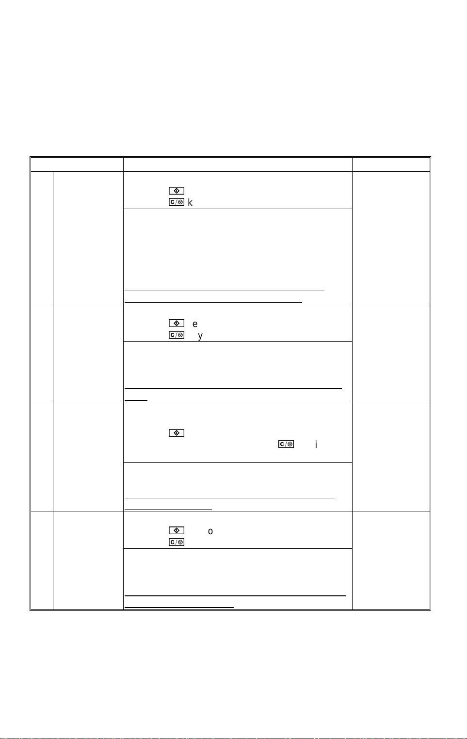
PROGRAM MODES 20 December 1996
2.5 SERVICE PROGRAM MODE TABLE
1. In the
2. In the
Function
Settings
column, comments (extra information) are in italics.
column, the default value is printed in bold letters.
3. If there is a ✝ mark in the Mode No. column, copies can be made within
this SP Mode.
Mode No. Function Settings
Forced Start
(Free Run)
4
Free Run with
Exposure
Lamp Off
5
Misfeed
Detection Off
6
Free Run Performs a free run with the exposure lamp on.
7
Performs a free run with a forced start.
Press the key to start the free tun.
Press the key to stop the free run.
If this mode is swi t ched on, the copier st ar ts the free
run even if the fusing temperature has not reached
the required value yet.
This mode i s per f o r m ed w i t h the selected paper size
and magnif i cat i on ratio without the paper feed clutch
or total counter increment.
Normally, use SP7 to prevent fusing-related
service call conditions from occurring.
A free run is performed without exposure.
Press the key to start the free run.
Press the key to stop the free run.
This mode i s per f o r m ed w i t h the selected paper size
and magnif i cat i on ratio without the paper feed clutch
or total counter increment.
Normally, u se SP7 t o reduce the cleaning blade
load.
Copies are made without misf eed detection by the
registration, exit sensors, and sorter paper sensor.
✝
Press the key to make a copy. It stops when
reaching th e set count, or when the key is
pressed.
Use this mode to check whether a pap er misfeed
was caused b y a sensor malfunction.
The total counter increments when copi es ar e
made in this mode.
Press the key to start the free run.
Press the key to stop the free run.
This mode i s per f o r m ed w i t h the selected paper size
and magnif i cat i on ratio without the paper feed clutch
or total counter increment.
Before starting, close the platen cover to reduce
the clea n ing blade lo ad.
4-10
 Loading...