

Page 1
SF-S54N
CODE : 00ZSFS54N/1AE
COPIER-MOUNTED TYPE
10-BIN STAPLE SORTER
MODEL SF-S54N
CONTENTS
[ 1 ] SPECIFICATIONS . . . . . . . . . . . . . . . . . . . . . . . . . . . . . . . . . . . . .1
[ 2 ] UNPACKING AND INSTALLATION . . . . . . . . . . . . . . . . . . . . . . . .1
PARTS GUIDE
Parts marked with "!" is important for maintaining the safety of the set. Be sure to replace these parts with specified
ones for maintaining the safety and performance of the set.
This document has been published to be used
SHARP CORPORATION
for after sales service only.
The contents are subject to change without notice.
Page 2
SF-S54N
[1] SPECIFICATIONS
(5) No. of sheets accommodated:
In staple sort mode A4 (81⁄2 × 11") 30 sheets
B4 (81⁄2 × 14") 15 sheets
A3 (11 × 17") 15 sheets
In sort mode A4 (81⁄2 × 11") 30 sheets
B4 (81⁄2 × 14") 15 sheets
A3 (11 × 17") 15 sheets
In group mode A4 (81⁄2 × 11") 20 sheets
B4 (81⁄2 × 14") 15 sheets
A3 (11 × 17") 15 sheets
In non-sort mode A4 (81⁄2 × 11") 100 sheets
B4 (81⁄2 × 14") 60 sheets
A3 (11 × 17") 60 sheets
(8) Capacity: 30 sheets/minute
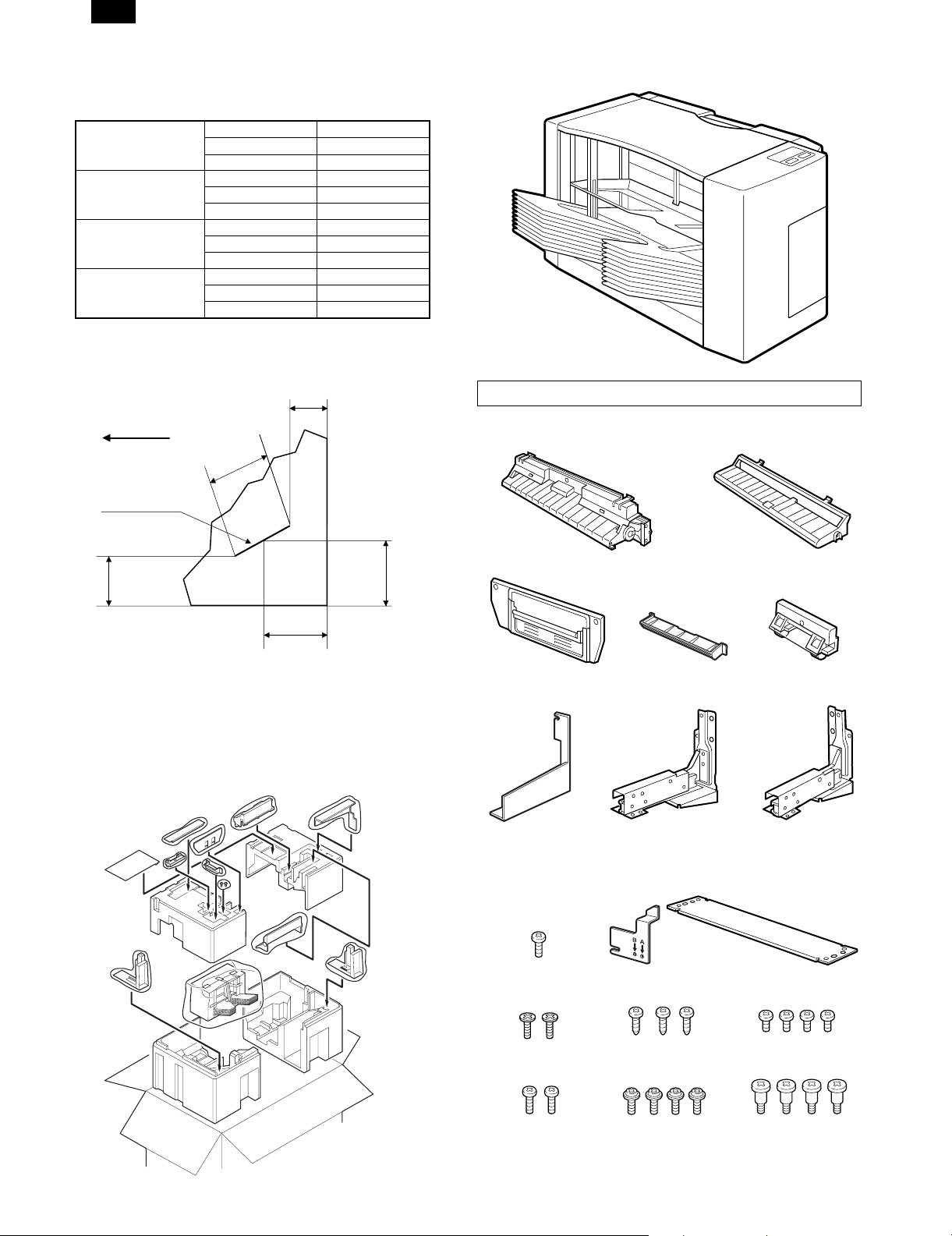
6. Binding reference: Operator’s side corner
Paper is discharged
in this direction
Staple
(see the figure below)
2~9
mm
(10.13)
mm
2. Instal lation
For use with copier model: S F-2530
Parts to be used
Connection unit
(1 pc.)
Support guide
(1 pc.)
2~9
mm
(11.5)
mm
[2] UNPACKING AND
INSTALLATION
1. Unpacki ng
Undo the package, referring to the sketch given below.
(9.5)
mm
Lock plate A
(1 pc.)
F cover
(1 pc.)
Switch plate securing screw
M3 x 6 (1 pc.)
Sorter seat R
Switch plate
(1 pc.)
Lock plate B
(1 pc.)
(1 pc.)
Sorter seat M
(1 pc.)
Roller unit
(1 pc.)
Sorter seat F
(1 pc.)
2/2/1999 – 1 –
F cover securing screws
(M4 x 10) (2 pcs.)
Lock plate securing screws
(M4 x 10) (2 pcs.)
Roller unit/support guide
securing screws
(3 pcs.)
Sorter securing screws
(M4 x 8) (4 pcs.)
Sorter seat M securing screws
(M4 x 5) (4 pcs.)
Sorter seat securing screws
(4 pcs.)
Page 3
SF-S54N
Disconnect the copier’s main power plug before
carrying out the procedure below.
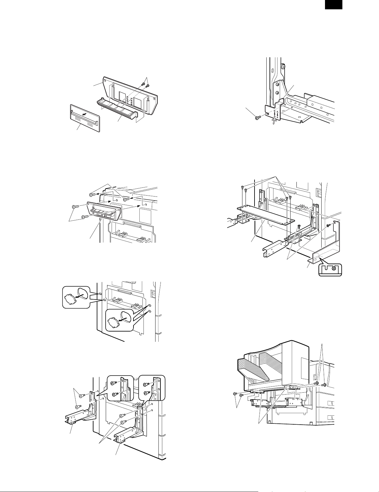
1. Mount the lock plate.
Remove the securing screws on the rear side of lock plate A.
Detach the lock plate being set and replace it with the lock plate B
supplied together with the copier, then fix it with the securing screws.
Screws
Lock plate A
Lock plate B
Lock plate
Remove the securing screws (2 pcs.) on the upper left cabinet panel
of copier main body.
Attach the lock plate A onto the left upper cabinet panel of copier
main body and fix it with the lock plate securing screws M4 x 10 (2
pcs.).
Upper left cabinet panel securing screws
3. Attach the switch plate.
Fit the positioning hole indicated with mark B to the switch plate
positioning portion on the sorter seat at the rear side and secure it
with the switch plate securing screw.
Switch plate
Securing screws
4. Mount sorter seat M.
Mount sorter seat M to sorter seats F and R, and secure it with the
M4 x 5 sorter seat M securing screws (4).
Then, attach the F cover to the sorter seat R and secure it with the F
cover securing screws M4 x 8 (2 pcs.).
Sorter seat M securing screws
Lock plate
securing screws
Lock plate A
2. Mount sorter seat F and sorter seat R.
Cut off the notch part (4 places) of the left cabinet panel of copier
main body.
Secure the sorter seat F to the rear side of the left cabinet of the
copier and the sorter seat R to the front side of the left cabinet with
the sorter seat securing screws (two for each).
Sorter seat
securing screws
Sorter seat M
F cover securing screws
F cover
5. Mount the sorter to the copier.
Mount the sorter onto sorter seats F and R.
Make sure that the protruding parts on the bottom of the sorter fit
securely into sorter seats F and R.
Next, secure the sorter by screwing in the M4 x 8 sorter securing
screws (2 for each sorter seat).
Sorter
securing screws
Sorter seat F
Sorter seat
securing screws
Sorter securing
screws
Protruding parts
Sorter seat R
– 2 – 2/2/1999
Page 4

SF-S54N
6. Mount the connection unit.
Fix the roller unit to the connection unit, using a securing screw (1
pc.).
Next, cut off the cutting portion ( ) of the support guide with a
nipper, then fix it to the connection unit with securing screws (2 pcs.).
Roller unit
securing screw
Cut
Support guide
securing screw
Support guide
Insert the connection unit’s lower tabs (2) into the tab slots inside the
back of the sorter.
Next, insert the upper tabs (2) into their tab slots to install the connection unit.
Tab (lower)
Tab (upper)
Roller unit
Connection unit
Cut
Support guide
securing screw
Tab (lower)
Tab (upper)
Connection unit
7. Connect the sorter connector.
Remove the securing screw of sorter connector cover attached to the
rear cabinet of copier main body, and detach the sorter connector
cover.
Connect the sorter connector to the copier main body connector, and
fix it with the sorter connector securing screw.
Before carrying out the procedures below, insert
the copier’s power plug into its outlet, and turn the
main power switch ON.
8. Set the mode.
• Set the mode with key operation on the copier.
C
Adding system: Enter a numeric value using the 10-key
pad which is obtained by adding the numbers shown
below that correspond to the options to be mounted.
RADF/ADF: 1 DESK: 4 SORTER: 10
Example: If the ADF and sorter are mounted: enter 11
(1 + 10 = 11).
0
0
The mode can be set with this operation.
1
6
2
Perform stapler-sorter function checks.
1. Check sort mode functioning.
Make 10 copies in the sort mode.
Check that the sorter deposits the copies in the sort bins.
2. Check non-sort mode functioning.
Make copies in the non-sort mode.
Check that copies are deposited in the non-sort bin.
3. Check staple-sort mode functioning.
Make copies in the staple-sort mode. Check that copies are deposited
in the s ort bi ns, tha t the staple g uide b ar aligns the cop ies and t hat
the staple unit staples them.
If copies are not stapled, follow the procedure below to make the
staples emerge correctly.
If copies are not stapled:
1. Remove the staple cartridge.
Open the sorter front cover.
Push up the stapler unit’s cartridge release lever, and remove the
staple cartridge from the stapler unit.
Sorter connector cover
Securing
screw
Sorter connector
2/2/1999 – 3 –
2. Close the sorter front cover, and remove the paper.
After removing the staple cartridge, close the sorter front cover.
Next, remove all the paper from the sort bins.
Page 5

3. Install the new staple cartridge.
Before installing the staple cartridge in the stapler unit, make sure
that the tips of the staples are flush with the indicator line on the
cartridge.
• If they are not, pull the staples outward until they are.
• If they protrude beyond the indicator lines, cut them back so that
they are flush with the lines.
Switch plate securing screw
M3 x 6 (1 pc.)
Switch plate
(1 pc.)
SF-S54N
Sorter seat M
(1 pc.)
Indicator line
Open the sorter front cover.
Install the staple cartridge in the stapler unit.
Push the cartridge in until it clicks into place.
Close the sorter front cover.
Press the manual staple key 5 times until the first staple comes out,
to make the staples move into the stapling position.
F cover securing screws
(M4 x 10) (2 pcs.)
Lock plate securing screws
(M4 x 10) (2 pcs.)
Roller unit/support guide
securing screws
(3 pcs.)
Sorter securing screws
(M4 x 8) (4 pcs.)
Sorter seat M securing screws
(M4 x 5) (4 pcs.)
Sorter seat securing screws
(4 pcs.)
Disconnect the copier’s main power plug before
carrying out the procedure below.
1. Mount the lock plate.
Remove the securing screws (2 pcs.) of the copier main body upper
left cabinet panel.
Attach the lock plate A to the upper left cabinet panel of copier main
body and fix it with lock plate securing screws M4 x 10 (2 pcs.).
Upper left cabinet panel securing screws
Lock plate
securing screws
Lock plate A
For use with copier model: SF-1020/1120/2020/2120
SF-1116/1118/2216/2218
Parts to be used
Connection unit
(1 pc.)
Lock plate A
(1 pc.)
F cover
(1 pc.)
Sorter seat F
(1 pc.)
Support guide
(1 pc.)
Roller unit
(1 pc.)
Sorter seat R
(1 pc.)
2. Mount sorter seat F and sorter seat R.
Remove the mask seals (2) from the left cabinet panel of the copier.
Mask seals
Pull out the rails of the sorter seats F and R and remove the spacers
with a flat-blade screwdriver or the like.
Spacer
Spacer
– 4 – 2/2/1999
Page 6

SF-S54N
Next, secure sorter seats F and R to the left cabinet panel with the
sorter seat securing screws (2 for each seat).
Sorter seat
securing screws
Sorter seat R
Sorter seat
securing screws
Sorter seat F
3. Attach the switch plate.
Fit the positioning hole indicated with mark A to the switch plate
positioning portion on the sorter seat at the rear side and secure it
with the switch plate securing screw.
Switch plate
Securing screw
5. Mount the sorter to the copier.
Mount the sorter onto sorter seats F and R.
Make sure that the protruding parts on the bottom of the sorter fit
securely into sorter seats F and R.
Next, secure the sorter by screwing in the M4 x 8 sorter securing
screws (2 for each sorter seat).
Sorter
securing screws
Sorter securing
screws
Protruding parts
6. Mount the connection unit.
• If the sorter is an SF-1120 or SF-2120:
Mount the connection unit as it is (see figure on right).
[Mounting Method]
Insert the connection unit’s lower tabs (2) into the tab slots inside
the back of the sorter.
Next, insert the upper tabs (2) into their tab slots to install the
connection unit.
4. Mount sorter seat M.
Mount sorter seat M to sorter seats F and R, and secure it with the
M4 x 5 sorter seat M securing screws (4).
Then, attach the F cover to the sorter seat F and secure it with the
two F cover securing screws (M4 x 8).
Sorter seat M securing screws
Sorter seat M
F cover securing screws
F cover
F cover
Tab (lower)
Tab (upper)
Tab (lower)
Tab (upper)
Connection unit
• If the sorter is an SF-1020 or SF-2020:
• If the sorter is an SF-1116/1118/2216/2218:
Remove the Mylar sheet pasted to the roller unit.
Mylar sheet
First mount the roller unit to the connection unit and secure it with
a securing screw (1).
Next, mount the support guide to the connection unit and secure it
with the other securing screws (2). Then mount the connection
unit.
After that, attach the connection unit according to [Mounting
Method] described above.
2/2/1999 – 5 –
Page 7

SF-S54N
Roller unit
securing screw
Support guide
securing screw
Support guide
Roller unit
Connection unit
Support guide
securing screw
8. Connect the sorter connector.
Remove the securing screw from the sorter connector cover, which is
mounted on the copier’s rear cabinet panel, and remove the sorter
connector cover by turning it in the direction of the arrow.
Connect the sorter connector to the connector on the copier and
secure it using the sorter connector securing screw.
Sorter connector
Securing
screw
Securing screw
Securing cover
2. Close the sorter front cover, and remove the paper.
After removing the staple cartridge, close the sorter front cover.
Next, remove all the paper from the sort bins.
3. Install the new staple cartridge.
Before installing the staple cartridge in the stapler unit, make sure
that the tips of the staples are flush with the indicator line on the
cartridge.
• If they are not, pull the staples outward until they are.
• If they protrude beyond the indicator lines, cut them back so that
they are flush with the lines.
Before carrying out the procedures below, insert
the copier’s power plug into its outlet, and turn the
main power switch ON.
Perform stapler-sorter function checks.
1. Check sort mode functioning.
Make 10 copies in the sort mode.
Check that the sorter deposits the copies in the sort bins.
2. Check non-sort mode functioning.
Make copies in the non-sort mode.
Check that copies are deposited in the non-sort bin.
3. Check staple-sort mode functioning.
Make copies in the staple-sort mode.
Check that copies are deposited in the sort bins, that the staple guide
bar aligns the copies and that the staple unit staples them.
If copies are not stapled, follow the procedure below to make the
staples emerge correctly.
If copies are not stapled:
1. Remove the staple cartridge.
Open the sorter front cover.
Push up the stapler unit’s cartridge release lever, and remove the
staple cartridge from the stapler unit.
Indicator line
Open the sorter front cover.
Install the staple cartridge in the stapler unit.
Push the cartridge in until it clicks into place.
Close the sorter front cover.
Press the manual staple key 5 times until the first staple comes out,
to make the staples move into the stapling position.
– 6 – 2/2/1999
Page 8

SF-S54
q
COPYRIGHT © 1999 BY SHARP CORPORATION
All rights reserved.
Printed in Japan.
No part of this publication may be reproduced,
stored in a retrieval system, or transmitted,
in any form or by any means,
electronic, mechanical, photocopying, recording, or otherwise,
without prior written permission of the publisher.
SHARP CORPORATION
Printing & Reprographic Systems Group
Quality & Reliability Control Center
Yamatokoriyama, Nara 639-1186, Japan
1999 January Printed in Japan
 Loading...