

Page 1
SERVICE MANUAL
S9310R25ATH//
COMMERCIAL
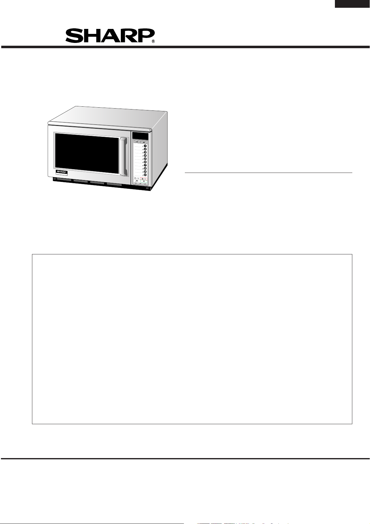
MICROWAVE OVEN
R-25AT
MODEL
1800W/R-23AT
TABLE OF CONTENTS
CAUTION, MICROWAVE RADIATION....................................................................... INSIDE FRONT COVER
WARNING ..........................................................................................................................................................1
SERVICING ...................................................................................................................................................... 2
PRODUCT SPECIFICATIONS ......................................................................................................................... 5
GENERAL INFORMATION ................................................................................................................................5
APPEARANCE VIEW ....................................................................................................................................... 6
OPERATION SEQUENCE................................................................................................................................ 7
FUNCTION OF IMPORTANT COMPONENTS ................................................................................................ 9
TROUBLESHOOTING GUIDE ........................................................................................................................10
TEST PROCEDURE ........................................................................................................................................ 12
TOUCH CONTROL PANEL ASSEMBLY ........................................................................................................ 18
COMPONENT REPLACEMENT AND ADJUSTMENT PROCEDURE ........................................................... 26
MICROWAVE MEASUREMENT .................................................................................................................... 33
TEST DATA AT A GLANCE ........................................................................................................................... 34
WIRING DIAGRAM ......................................................................................................................................... 35
PICTORIAL DIAGRAM ................................................................................................................................... 37
CONTROL PANEL CIRCUIT ...........................................................................................................................38
PRINTED WIRING BOARD .............................................................................................................................39
PARTS LIST ................................................................................................................................................... 40
In interests of user-safety the oven should be restored to its
original condition and only parts identical to those specified
should be used.
R-25AT
Page
SHARP CORPORATION
Page 2

R-25AT
CAUTION
MICROWAVE RADIATION
Personnel should not be exposed to the microwave energy which may radiate from the
magnetron or other microwave generating devices if it is improperly used or connected.
All input and output microwave connections, waveguides, flanges and gaskets must be
secured.
Never operate the device without a microwave energy absorbing load attached.
Never look into an open waveguide or antenna while the device is energized.
VARNING
MICKROVAGSSTRALING
Personal får inte utsättas för mikrovågsenergi som kan ustrala från magnetronen eller
andre mikrovågsalstrande anordningar om dessa är felanslutna eller används på fel sätt.
Alla in-och utgångsanslutningar för mikrovågor, vagledare, flänsar och packningar måste
vara fast anslutna.
Mikrovågsgeneratorn får inte arbeta utan att absorberande belastning är ansluten. Titta
aldrig in i ën öppen vågledare eller antenn när mikrovågsgeneratorn är påkopplad eller
laddad.
VAROITUS
MIKROAALTOSÄTELYÄ
Käyttäjä ei saa joutua alttiiksi mikroaaltoenergialle, jota voi säteillä magnetronista tai
muusta mikroaaltoja kehittävästä laitteesta, jos sitä käytetään tai jos se kytketään väärin.
Kaikkien mikroaaltoliitäntöjen sekä syöttö-että ulostulopuolella, aaltoputkien laippojen ja
tiivisteiden tulee olla varmistettuja.
Mikroaaltouunnia ei koskaan saa käyttää ilman kuormaa jossa mikroaaltoenergiaa kuluu.
Avoimeen aaltoputkeen tai antenniin ei koskaan saa katsoa virran ollessa kytkettynä.
ADVARSEL
MIKROBØLGESTRÅLING
Personell må ikke utsettes for mikrobølge-energi som kan utståles fra magnetronen eller
andre mikrobølge-generende deler dersom apparatet feilbetjenes eller blir feiltikoplet.
Alle inn-og ut-tilkoplinger i forbindelse med mikrobølge-strålingen, bølgeledere, flenser og
tetningsringer/pakninger må festes ordentlig.
Aldri bruk apparatet med mindre en mikrobålge-absorberende last er plassert i
ovnsrommet.
Aldri se direkte inn i en åpen bølgeleder eller antenne imens apparatet er strømførende.
ADVARSEL
MIKROBØLGEBESTRÄLING
Man bør ikke udsætte sig for mikrobølgebestråling fra magnetronen eller andre
mikrobølgefrembringende anordninger, hvilket kan ske hvis apparatet er forkert tilsluttet
eller bruges forkert. Alle mikrobølgeindgange og-udgange, bølgeledere, flanger og
tætningsstrimler må være forsvarligt udført.
Anvend aldrig ovnen uden en mikrobølgesabsorberende anordning. Se aldrig ind i en
åben bølgeleder eller antenne, mens ovnen er i brug.
Page 3
SERVICE MANUAL
COMMERCIAL MICROWAVE OVEN
R-25AT
R-25AT
SERVICING
PRODUCT SPECIFICATIONS
GENERAL IMPORTANT INFORMATION
This Manual has been prepared to provide Sharp Corp. Service
engineers with Operation and Service Information.
It is recommended that service engineers carefully study the entire
text of this manual, so they will be qualified to render satisfactory
customer service.
CAUTION
MICROWAVE RADIATION
DO NOT BECOME EXPOSED TO RADIATION FROM THE
MICROWAVE GENERATOR OR OTHER PARTS THAT CONDUCT MICROWAVE ENERGY.
WARNING
Note: The parts marked "*" are used in voltage more
than 250V. (Parts List)
Anm: Delar märket med "*" har en spänning
överstigande 250V.
Huom: Huolto-ohjeeseen merkitty "tähdella" osat joissa
jännite on yli 250 V.
Bemerk: Deler som er merket "asterisk" er utsatt for
spenninger over 250V til jord.
GENERAL INFORMATION
APPEARANCE VIEW
OPERATING SEQUENCE
FUNCTION OF IMPORTANT
COMPONENTS
TROUBLESHOOTING GUIDE
AND TEST PROCEDURE
TOUCH CONTROL PANEL
COMPONENT REPLACEMENT
AND ADJUSTMENT PROCEDURE
Bemærk: "Dele mærket med stjerne benyttes med højere
spænding end 250 volt.
WARNING
Never operate the oven until the following points are ensured.
(A) The door is tightly closed.
(B) The door brackets and hinges are not defective.
(C) The door packing is not damaged.
(D) The door is not deformed or warped.
(E) There is not any other visible damage with the oven.
Servicing and repair work must be carried out only by trained service
engineers.
All the parts marked "*" on parts list are used at voltage more than
250V.
Removal of the outer wrap gives access to potential above 250V.
All the parts marked "∆" on the parts list may cause undue
microwave exposure, by themselves, or when they are damaged,
loosened or removed.
SHARP CORPORATION
MICROWAVE MEASUREMENT
TEST DATA AT A GLANCE
WIRING DIAGRAM
PARTS LIST
OSAKA, JAPAN
1
Page 4
R-25AT
SERVICING
WARNING TO SERVICE PERSONNEL
GB Microwave ovens contain circuitry capable of producing very high voltage and current, contact with following parts will result
in electrocution. High voltage capacitor, High voltage transformer, Magnetron, High voltage rectifier assembly, High voltage
fuses, High voltage harness.
REMEMBER TO CHECK 3D
1) Disconnect the supply.
2) Door opened, and wedged open.
3) Discharge two high voltage capacitors.
WARNING: AGAINST THE CHARGE OF THE TWO
HIGH-VOLTAGE CAPACITORS
The two high-voltage capacitors remains charged about 60
seconds after the oven has been switched off. Wait for 60
seconds and then short-circuit the connection of the two
high-voltage capacitors (that is, of the connecting lead of the
high-voltage rectifier) against the chassis with the use of an
insulated screwdriver.
Sharp recommend that wherever possible fault-finding is
carried out with the supply disconnected. It may in, some
cases, be necessary to connect the supply after the outer
case has been removed, in this event carry out 3D checks and
then disconnect the leads to the primary of the two High
voltage transformers. Ensure that these leads remain isolated
from other components and the oven chassis. (Use insulation
tape if necessary.) When the testing is completed carry out 3D
checks and reconnect the leads to the primary of the two High
voltage transformers.
NL Magnetronovens bevatten circuits die een zeer hoge spanning en stroom kunnen voortbrengen. Contact met de
volgende onderdelen kan elektrocutie tot gevolg hebben.
Hoogspanningscondensator, hoogspanningstransformator, magnetron, hoogspanningsgelijkrichter, hoogspannings
kabelboom.
REMEMBER TO CHECK 4R
1) Reconnect all leads removed from components during
testing.
2) Replace the outer case (cabinet).
3) Reconnect the supply.
4) Run the oven. Check all functions.
Microwave ovens should not be run empty. To test for the
presence of microwave energy within a cavity, place a cup of
cold water on the oven turntable, close the door and set the
power to HIGH and set the microwave timer for one (1) minute.
When the one minute has elapsed (timer at zero) carefully
check that the water is now hot. If the water remains cold carry
out
3D checks and re-examine the connections to the compo-
nent being tested.
When all service work is completed, and the oven is fully
assembled, the microwave power output should be checked and
a microwave leakage test should be carried out.
VERGEET DE VOLGENDE 3 STAPPEN NIET
1) Haal de stekker uit het stopcontact.
2) Open de deur en zorg ervoor dat hij niet dicht kan vallen.
3) Ontlaad de hoogspanningscondensator.
PAS OP VOOR DE ELECTRISCHE LADING VAN DE
HOOGSPANNINGSCONDENSATOR
De hoogspanningscondensator blijft nog ongeveer 60
seconden lang opgeladen, nadat de oven is uitgeschakeld.
Wacht 60 seconden voordat u de verbinding van de
hoogspannings-condensator (m.a.w. de verbindingsdraad
van de hoogspanningsgelijkrichter) met een geïsoleerde
schroevedraaier kortsluit tegen het chassis.
Sharp beveelt ten sterkste aan dat, voor zover mogelijk,
defecten worden opgespoord wanneer de stekker uit het
stopcontact is gehaald. Soms is het nodig om de stroomtoevoer
weer tot stand te brengen nadat de buitenmantel verwijderd
is. Herhaal dan de bovengenoemde 3 stappen en haal de
electrische draden uit de primaire zijde van de
vermogenstransformator. Zorg ervoor dat deze draden
geïsoleerd blijven van andere elementen en van het chassis
van de oven. (Gebruik zo nodig isolatieband.) Wanneer de
test is uitgevoerd, herhaalt u de bovenstaande 3 stappen en
verbindt u de electrische draden weer aan de primaire zijde
van de vermogenstransformator.
VERGEET DE VOLGENDE 4 STAPPEN NIET
1) Sluit de draden weer aan diezijn losgehaald voor de test.
2) Plaats de buitenmantel weer om het toestel heen (kabinet).
3) Stop de stekker weer in het stopcontact.
4) Zet de oven aan. Controleer alle functies.
Magnetronovens mogen niet leeg aangezet worden. Om te
controleren of er microgolf-energie binnen de oven wordt
geproduceerd, plaatst u een mok met koud water op de
draaitafel van de oven, sluit de deur, zet de oven op HIGH en
stelt de klok van de magnetron in op twee (2) minuten. Wanneer
de twee minuten voorbij zijn (klok staat op nul), controleert u
voorzichtig of het water heet is. Indien het water nog steeds
koud is, herhaalt u de allereerste drie stappen en controleer
nogmaals de aansluitingen naar de geteste onderdelen.
Wanneer alle reparaties zijn uitgevoerd en de oven weer in
elkaar is gezet, moet de het magnetronvermogen worden
gecontroleerd en moet worden gecontroleerd of er geen
microgolflekkage is.
2
Page 5
R-25AT
E Los hornos de microondas contienen circuitos eléctricos capaces de producir voltajes de alta tensión y descargas
eléctricas. Para evitar el riesgo de electrocución, absténgase de tocar los siguientes componentes: condensador de alta
tensión, transformador de alta tensión, magnetrón, dispositivo del rectificador de alta tensión y arnés de alta tensión.
RECUERDE LA COMPROBACION 3D
1) Desconecte la alimentación.
2) Deje la puerta abierta y calzada.
3) Descargue el condensador de alto voltaje.
ADVERTENCIA SOBRE LA CARGA DEL
CONDENSADOR DE ALTO VOLTAJE
El condensador de alto voltaje permanece cargado unos
60 segundos después de haber apagado el horno. Espere
60 segundos y luego ponga en cortocircuito la conexión del
condensador de alto voltaje (esto es, del conductor de
conexión del rectificador de alto voltaje) al chasis con un
destornillador de mango aislado.
Se recomienda encarecidamente que siempre que sea
posible la localización de fallos se realice con la alimentación
desconectada. Puede ser que en algunos casos sea
necesario conectar la alimentación después de haber retirado
la carcasa exterior. En este caso, realice las comprobaciones
3D y luego desconecte los conductores del primario del
transformador de alimentación. Asegúrese de que estos
conductores permanezcan aislados de otros componentes y
del chasis del horno. (Use cinta aislante si es necesario).
Cuando termine la prueba efectúe las comprobaciones 3D y
reconecte los conductores al primario del transformador de
alimentación.
RECUERDE LA COMPROBACION 4C
1) Conecte todos los componentes desconectados de los
componentes durante la prueba.
2) Coloque la carcasa exterior (cabina).
3) Conecte la alimentación.
4) Compruebe todas sus funciones despues de poner en
marcha el horno.
Los hornos de microondas no deben funcionar vacíos. Para
comprobar la presencia de energía de microondas dentro de
una cavidad, coloque una taza de agua fría en el plato giratorio
del horno, cierre la puerta y ponga la potencia en HIGH (alta)
y coloque el temporizador en dos (2) minutos. Cuando
transcurran los dos minutos (temporizador a cero) compruebe
cuidadosamente que el agua se ha calentado. Si el agua
permaneciese fría, efectúe las comprobaciones 3D y vuelva a
examinar las conexiones de los componentes que han sido
probados.
Cuando haya terminado la intervención en el equipo y el horno
haya sido ensamblado de nuevo completamente, deberá
comprobar la potencia de salida de microondas y realizar una
prueba de fugas de microondas.
SV Mikrovågsugnar innehåller kretsar som producerar mycket höga spänningar och strömmar.
Kontakt med följande komponenter kan leda till dödsfall:
Högspänningskondensator, transformator, magnetron, högspännings likriktare, högspännings kablage.
KOM IHÅG ATT KONTROLLERA 3 STEG
1) Koppla från strömkällan.
2) Öppna dörren på glänt.
3) Ladda ur högspänningskondensatorn.
VARNING FÖR LADDNINGEN I
HÖGSPÄNNINGSKONDENSATORN
Högspänningskondensatorn är laddad i 60 sekunder efter
det att ugnen stängts av. Vänta 60 sekunder och korislut
sedan kondensatoms anslutning (dvs anslutningen till
högspänningslikriktaren) till chassiet med hjälp av en isolerad
skruvmejsel.
Sharp rekommenderar att felsökning sker med strömmen
fränkopplad. Ibland kan det var nödvändigt att koppla på
strömmen efter det att höljet avlägsnats, utför da 3 Steg
kontrollen och koppla sedan från ledarna till transformatorns
primärsida. Se till att ledarna är isolerade från andra
komponenter och chassiet. (Använd isoleringsband om det
behövs). När Du testat färdigt utför Du 3 Steg kontrollen och
ansluter ledningarna till transformatorns primärsida igen.
KOM IHÅG ATT KONTROLLERA 4 STEG
1) Anslut alla ledningar som använts vid testning
2) Sätt tillbaka ytterhöljet.
3) Anslut strömkällan på nytt.
4) Sätt på ugnen. Kontrollera alla funktioner.
Mikrovågsugnar får inte användas tomma. Kontrollera
mikrovågsstrålningen i olika delar av ugnen genom att placera
en kopp med kallt vatten på ugnens tallrik, stäng dörren, ställ
in HIGH och ställ in 2 minuter på timern. När två minuter har gått
(timem visar 0) kontrollerar du om vattnet är varmt. Om vattnet
fortfarande är kallt utför Du 3 steg kontroller och kontrollerar
anslutningarna till varje enskild komponent på nytt.
När all service är klar och ugnen ihopskruvad skall ugnens
uteffekt och eventuellt mikrovågsläckage kontrolleras.
3
Page 6

R-25AT
II forni a microonde contengono un circuito elettrico in grado di generare tensioni e correnti estremamente elevate.
L’eventuale contatto con i seguenti componenti può causare la folgorazione:
condensatore ad alta tensione; trasformatore ad alta tensione; magnetron; rettificatore alta tensione; cablaggio ad
alta tensione.
TRE OPERAZIONI IMPORTANTI PER
INCOMINCIARE
1) Scollegare l'alimentazione elettrica.
2) Verificare che la porta sia bloccata in posizione
aperta.
3) Scaricare il condensatore ad alta tensione.
ATTENZIONE AL CONDENSATORE AD ALTA
TENSIONE: PUO ESSERE CARICO
Il condensatore ad alta tensione rimane carico per circa
60 secondi dopo lo spegnimento del forno. Occorre quindi
spettare 60 secondi prima di cortocircuitare, utilizzando
un cacciavite con impugnatura isolata, il collegamento
del condensatore ad alta tensione (cioè del conduttore
di collegamento del raddrizzatore ad alta tensione) sul
telaio del forno.
Sharp raccomanda, nei limiti del possibile, che la ricerca
dei guasti avvenga in assenza di alimentazione elettrica.
In alcuni casi tuttavia, può essere necessario alimentare
l'apparecchio dopo aver rimosso la scatola esterna. In
questo caso eseguire i tre controlli sopra citati e quindi
scollegare i connettori dal primario del trasformatore.
Assicurarsi che tali connettori non vengano a contatto con
altri componenti, ne con il telaio del forno (fare uso, se
necessario, di nastro isolante). Al termine dell'intervento,
eseguire nuovamente i tre controlli e ricollegare i conduttori
al primario del trasformatore.
QUATTRO VERIFICHE IMPORTANTI DA NON
DIMENTICARE
1) Ricollegare tutti i conduttori staccati dai vari componenti
durante l'intervento.
2) Rimontare la scatola esterna.
3) Ripristinare l'alimentazione elettrica.
4) Rimettere in funzione il forno. Controllare tutte le funzioni.
I forni a microonde non devono mai funzionare a vuoto. Per
verificare la presenza di energia da microonde all'interno
di una cavitá, mettere una tazza di acqua fredda sul piatto
rotante del forno, chiudere la porta, regolare la potenza su
HIGH ed impostate il temporizzatore su due (2) minuti.
Tr ascorsi i due minuti (temporizzatore a zero), controllare
accuratamente che ora l'acqua sia calda. Se l'acqua è
rimasta fredda, eseguire i tre controlli iniziali e verificare
nuovamente i collegamenti del componente in questione.
Dopo aver portato a termine le operazioni di manutenzione
e rimontato il forno, è necessario controllare la potenza delle
microonde emesse ed eseguire un test per verificare che
non vi sia alcuna dispersione.
4
Page 7
PRODUCT DESCRIPTION
SPECIFICATION
ITEM DESCRIPTION
Power Requirements 230 Volts
50 Hertz
Single phase, 3 wire earthed
Power Comsumption
Power Output
Case Dimensions Width 510mm
Cooking Cavity Dimensions Width 330 mm
Control Complement Touch Control System
3.15 kW Approx. 15 A
2100 W nominal of RF microwave energy (measured by method of IEC 60705)
Operating frequency 2450 MHz
Height 335 mm
Depth 470mm
Height 180 mm
Depth 330mm
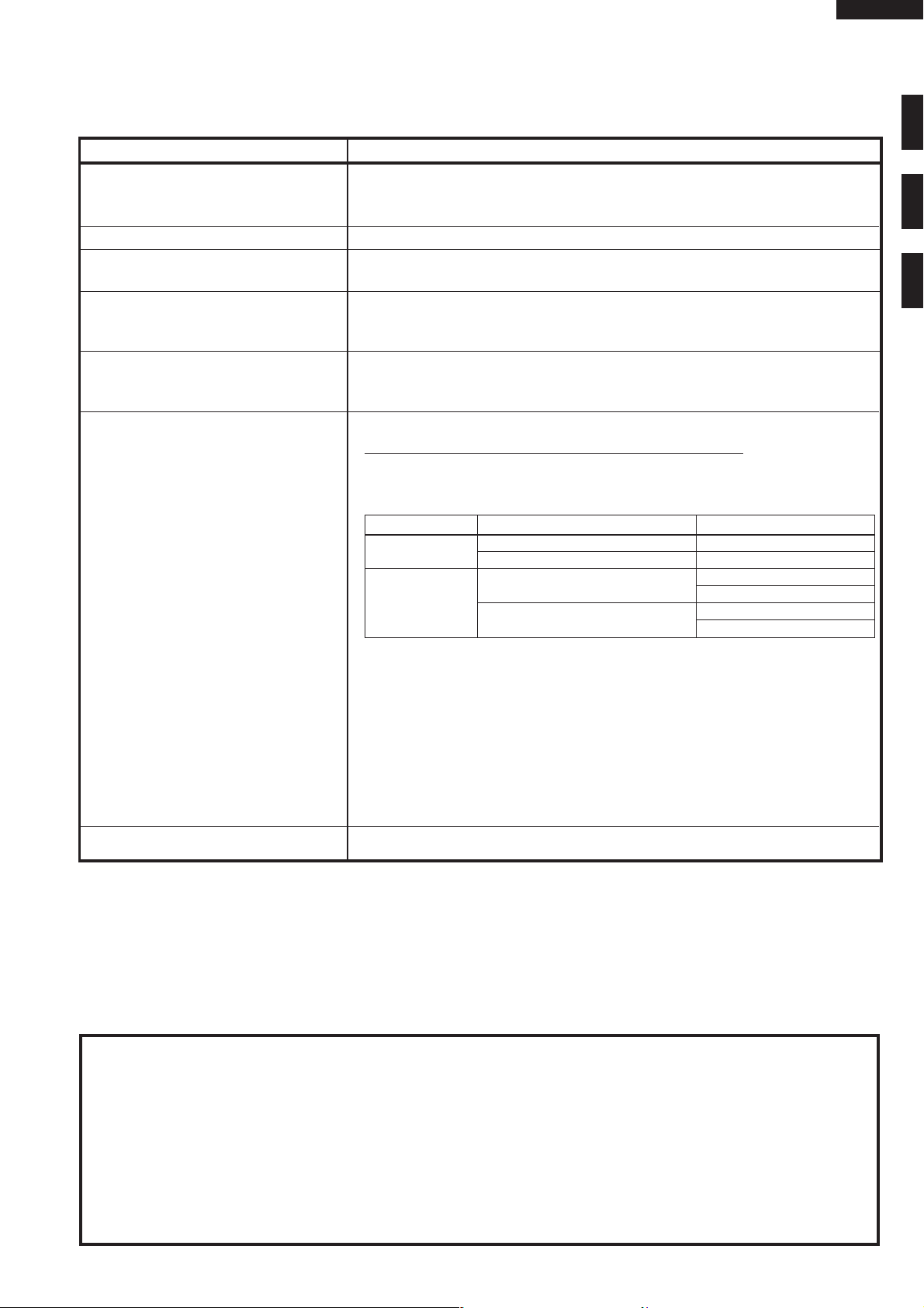
The combination of cooking time and microwave power
The oven can be programmed a series of up to 3 cookling stages.
The combination of microwave power and cooking time that can be input as
folllows.
Cooking Sequence Micrwave power level that can be used. Cooking time that can be used.
1 Stage only
2 or 3 Stage
0 - 40% Max. 30 minutes
50 - 100% Max. 15 minutes
0 - 40%
50 - 100%
Max. 30 minutes any stage
Max. 30 minutes in total
Max. 15 minutes any stage
Max. 15 minutes in total
R-25AT
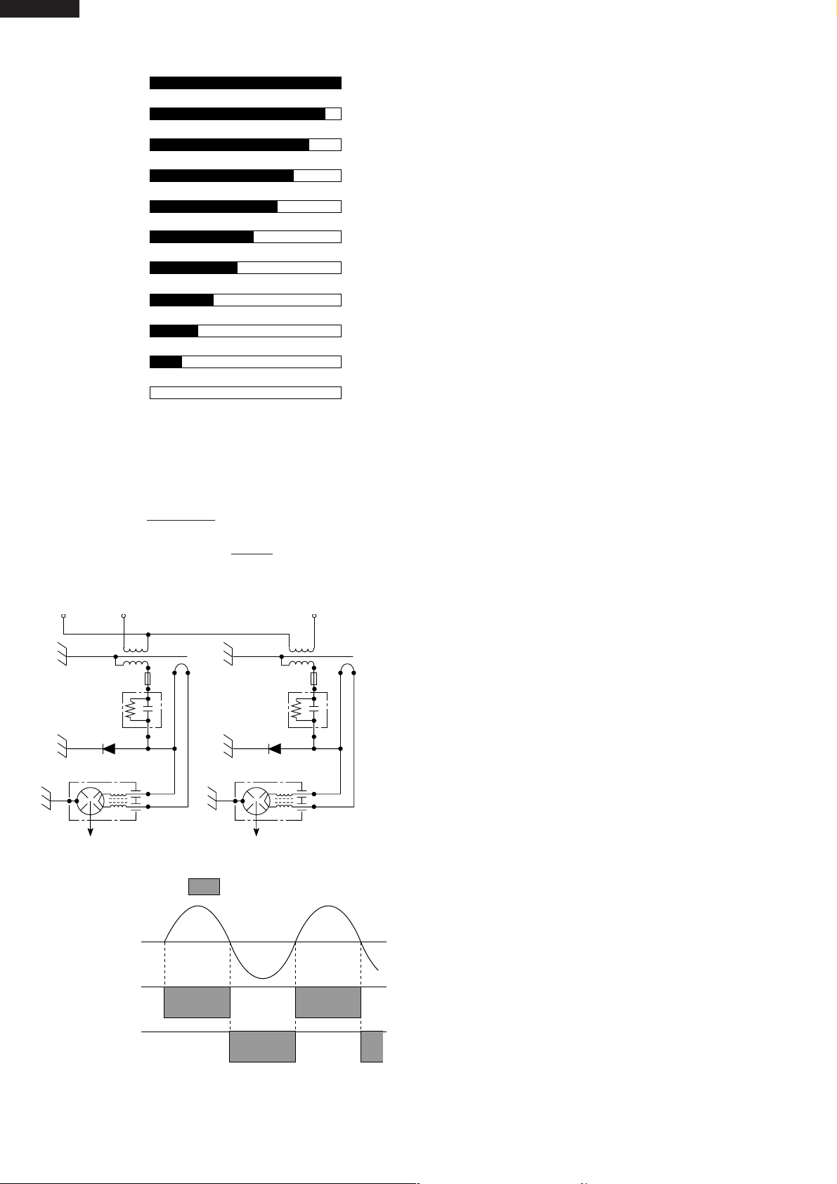
Microwave Power level
100% 90% 80% 70% 60% 50% 40% 30% 20% 10% 0%
MANUAL / REPEAT key, NUMBER keys
MICROWAVE POWER SETTING key
STOP / CLEAR key, START Key
DOUBLE QUANTITY key
EXPRESS DEFROST key, SET key
CHECK key, VOLUME key
Set Weight Approx. 33 kg
GENERAL INFORMATION
WARNING
THIS APPLIANCE MUST BE EARTHED
IMPORTANT
THE WIRES IN THIS MAINS LEAD ARE COLOURED IN ACCORDANCE WITH THE FOLLOWING CODE:
GREEN-AND-YELLOW : EARTH
BLUE : NEUTRAL
BROWN : LIVE
5
Page 8
R-25AT
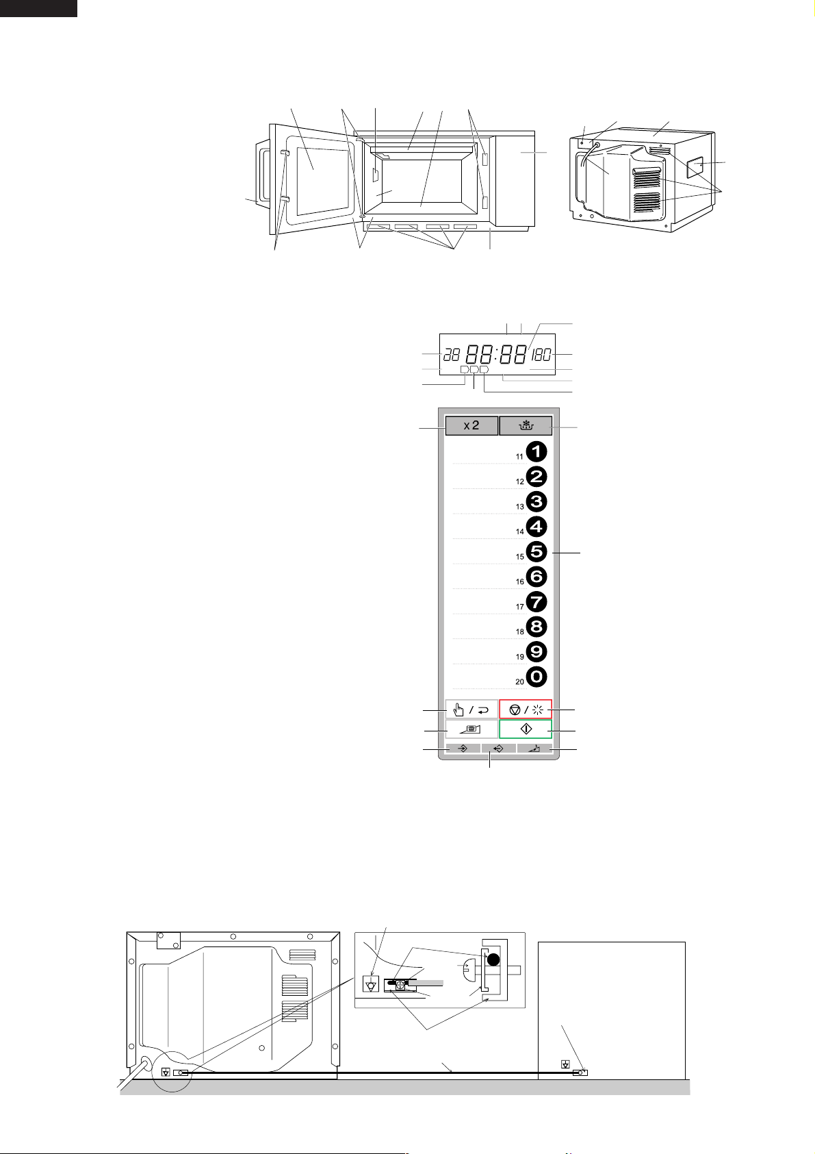
OVEN
1. Control panel
2. Hole for safety door latches
3. Ceramic floor
4. Splash cover
5. Oven light
6. Air intake filter
7. Air intake openings
8. Oven cavity
9. Door seals and sealing surfaces
10. Door hinges
11. Oven door with see-through window
12. Door safety latches
13. Door handle.
14. Outer cabinet
15. Removable cover over oven light bulb
16. Air vent openings
17. Power supply cord
18 Mounting plate
19 Screw for mounting plate
DISPLAY AND INDICATORS
Check indicators after the oven starts to
confirm the oven is operating as desired.
1. Cook indicator
This indicator shows cooking in progress.
2. Memory number indicator
3. Defrost indicator
4. Check mode indicator
5. Power level display
6. Digital display
7. Filter indicator
8. Double quantity mode indicator
9. 3rd. stage indicator
10. 2nd. stage indicator
11. 1st. stage indicator
OPERATING KEYS
12. DOUBLE QUANTITY key
13. EXPRESS DEFROST key
14. NUMBER keys
15. MANUAL/ REPEAT key
16. STOP/CLEAR key
17. MICROWAVE POWER SETTING key
18. START key
19. SET key
20. VOLUME key
21. CHECK key
13
APPEARANCE VIEW
11
12
10
5
8
AUTO TOUCH CONTROL PANEL
11
12
15
17
19
3
4
2
19
18
1
17
14
15
16
679
34
DEF
DOUBLE
21
CHECK
FILTER
NUMBER
2
1 2 3
ON
1
10
POWER
%
6
5
7
8
9
13
14
16
18
20
INSTALLATION INFORMATION
When this commercial microwave oven is installed near other commercial electrical appliances, connect a lead wire to
each equivalent potential terminal with equipotential marking between them (insert a lead wire between a washer and
an earth angle, and screw them), as shown in Fig. A-1, to make sure that they are at equivalent potential.
If any lead wire is not connected between them, when person touch them he/she will get a electric shock.
COMMERCIAL MICROWAVE OVEN OTHER COMMERCIAL
Equipotential marking
Lead wire
Screw
Washer
Earth angle
(Equivalent potential terminal)
Lead wire
Figure A-1
6
ELECTRICAL APPLIANCE
Equivalent
potential terminal
Page 9

OPERATION SEQUENCE
R-25AT
Closing the door activates all door interlock switches
(interlock switches and stop switch).
IMPORTANT
When the oven door is closed, the monitor switch contacts
COM-NC must be open. When the microwave oven is
plugged in a wall outlet (230 volts, 50Hz), the line voltage
is supplied to the control unit through the noise filter.
Figure O-1 on page 35
1. The digital display shows .
IDLE CONDITION
When the door is opened, the contacts of the interlock
switches SW1+SW2 and stop switch SW5 open, initiating
the following:
Figure O-2 on page 35
1. A signal is input to the control unit energizing the coil of
shut-off relay RY-1.
2. The shut-off relay RY-1 contacts close completing
circuits to turn on the oven lamp, blower motor and
antenna motors.
3. If the door remains open, 60 seconds later the control
unit de-energizes shut-off relay RY-1 turning off the
oven lamp, blower motor and antenna motors.
When the door is closed, the contacts of the interlock
switches SW1+SW2 and stop switch SW5 close. With the
closing of the stop switch SW5 contacts, an additional
circuit is provided which will permit the operation of the
oven when one of the touch pads is depressed. Since the
control is enabled through the stop switch SW5, the door
must be closed before the touch pads will be effective.
When the door is closed, a full 60 second IDLE condition
is always provided for selecting and pressing the desired
touch pads. A 60 second IDLE condition will also follow the
end of each cook cycle.
MICROWAVE COOKING CONDITION
Touch MANUAL/ REPEAT key and enter a desired
cooking time with the touching NUMBER key. And then
touch START key.
NOTE: The programme and the check are canceled
when any keys are not touched for more than
3 minutes during programming.
Function sequence Figure O-3 on page 36
CONNECTED COMPONENTS RELAY
Oven lamp/ Blower motor/ Antenna motors RY1
High voltage transformer T1 RY3
High voltage transformer T2 RY4
1. The line voltage is supplied to the primary winding of
the two high voltage transformers. The voltage is
converted to about 3.3 volts A.C. output on the filament
winding and high voltage of approximately 2000 volts
A.C. on the secondary winding.
2. The filament winding voltage (3.3 volts) heats the
magnetron filament and the high voltage (2000 volts) is
sent to the voltage doubling circuit, where it is doubled
to negative voltage of approximately 4000 volts D.C..
3. The 2450 MHz microwave energy produced in the
magnetron generates a wave length of 12.24 cm. This
energy is channelled through the waveguide (transport
channel) into the oven cavity, where the food is placed
to be cooked.
4. When the cooking time is up, a signal tone is heard and
the relays RY3+RY4 go back to their home position.
The circuits to the high voltage transformers T1+T2.
The relay RY1 remains and oven lamp, blower motor
and antenna motors work for 1 minute.
5. When the door is opened during a cook cycle, the
switches come to the following condition.
CONDITION
DURING DOOR OPEN
SWITCH CONTACT COOKING
Interlock switches COM-NO Closed Open
Monitor switches COM-NC Open Closed
Stop switch COM-NO Closed Open
(NO COOKING)
The circuits to the high voltage transformers T1+T2
are cut off when the interlock and stop switches
SW1+SW2+SW5 are made open. The blower motor
BM, antenna motors and oven lamp remains on even
if the oven door is opened after the cooking cycle has
been interrupted, because the relay RY1 stays closed.
Shown in the display is the remaining time, but the
program is cancelled if the oven is not started within 1
minute.
6. MONITOR SWITCH CIRCUIT
The monitor switches SW3+SW4 are mechanically
controlled by oven door, and monitors the operation of
the interlock switches SW1+SW2.
6-1. When the oven door is opened during or after the
cycle of a cooking program, the interlock switches
SW1+SW2 and stop switches SW5 must open their
contacts first. After that the contacts (COM-NC) of the
monitor switches SW3+SW4 can be closed.
6-2. When the oven door is closed, the contacts (COM-
NC) of the monitor switches SW3+SW4 must be
opened first. After that the contacts (COM-NO) of the
interlock switches SW1+SW2 and stop switch SW5
must be closed.
6-3. When the oven door is opened and the contacts of the
interlock switch SW1 (or SW2) remain closed, remains closed, the fuse F1 F10A (or F2 F10A) will
blow, because the monitor switch SW3 (or SW4) is
closed and a short circuit is caused.
MICROWAVE VARIABLE COOKING
When the microwave oven is preset for variable cooking
power, the line voltage is supplied to the high voltage
transformers T1+T2 intermittently within a 48 second time
base through the contacts of the relays RY3+RY4.
The following levels of microwaves power are given.
7
Page 10
R-25AT
48 sec. ON
Number key
44sec. ON
Number key 9
40 sec. ON
Number key 8
36 sec. ON
Number key 7
32 sec. ON
Number key 6
26 sec. ON
Number key 5
22 sec. ON
Number key 4
16 sec. ON
Number key 3
12 sec. ON
Number key 2
8 sec. ON
Number key 1
0 sec. ON
Number key 0
NOTE: The ON/OFF time ratio does not exactly corre-
spond to the percentage of microwave power,
because approx. 3 seconds are needed for heating up the magnetron filament.
TWO MAGNETRON OPERATION SYSTEM
Two magnetrons MG1+MG2 are equipped in order to get
higher microwave power output. The primary windings of
the high voltage transformers T1+T2 are connected so
that each magnetron can be oscillated alternatively according to the frequency of the power supply. Refer to the
Figure B-1 and B-2.
T2: HIGH VOLTAGE
TRANSFORMER
(REAR)
H. V. FUSE H. V. FUSE
H. V. RECTIFIER
MG2: MAGNETRON (LOWER)
C2: H.V. CAPACITOR
H. V. RECTIFIER
Figure B-1. High Voltage Circuit
OPERATION OF
MAGNETRON
MG1: MAGNETRON (UPPER)
T1: HIGH VOLTAGE
TRANSFORMER
(FRONT)
C1: H.V. CAPACITOR
COMMERCIAL
FREQUENCY
(50HZ)
POWER OUTPUT
BY MAGNETRON T1
POWER OUTPUT
BY MAGNETRON T2
Figure B-2. Operation of Magnetron
8
Page 11
FUNCTION OF IMPORTANT COMPONENTS
R-25AT
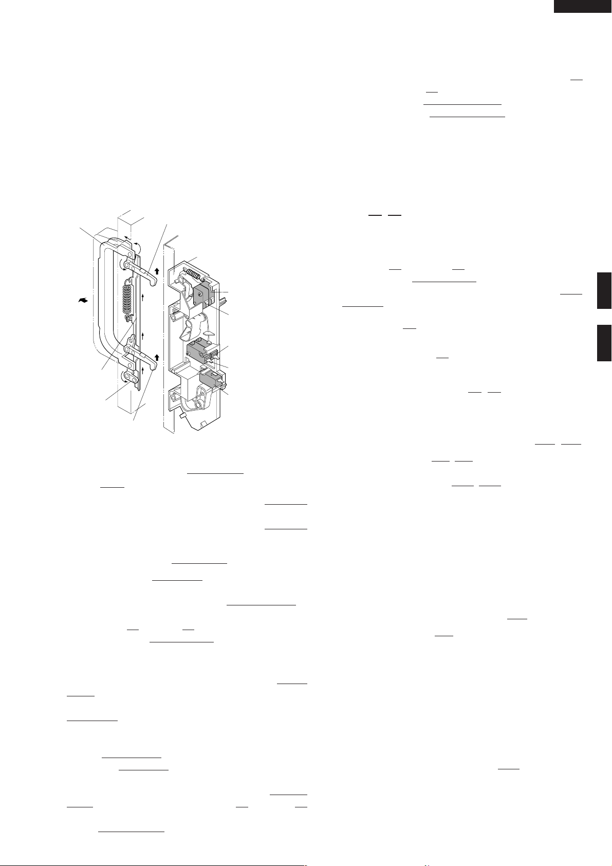
DOOR OPEN MECHANISM
1. The door release lever is pulled.
2. The upper latch head is lifted up by the linked door
release lever.
3. The head lever is lifted up by the door release lever.
4. The joint lever is lifted up by the head lever.
5. The lower latch head is lifted up by the joint lever.
6. Now both latch heads are lifted up, so they can be
released from the latch hook.
7. Now the door can be opened.
Door release
lever
Joint lever
Latch head
Latch hook
SW4: Monitor switch
(Oven side)
SW3: Monitor switch
SW2: Interlock switch
(Oven side)
SW1: Interlock switch
CAUTION:BEFORE REPLACING A BLOWN FUSE F1
F10A (OR F2 F10A) TEST THE INTERLOCK
SWITCH SW1 (OR SW2) AND MONITOR
SWITCHE SW3 (OR SW4) FOR PROPER
OPERATION. (REFER TO CHAPTER “TEST
PROCEDURE”).
NOISE FILTER
The noise filter assembly prevents radio frequency interference that might flow back in the power circuit.
FUSES F1, F2 F10A 250V
1. If the wire harness or electrical components are shortcircuited, this fuse blows to prevent an electric shock or
fire hazard.
2. The fuse F1 F10A (or F2 F10A) also blows when
interlock switch SW1 (or SW2) remains closed with the
oven door open and when the monitor switches SW3
(or SW4) closes.
WEAK POINT F3
If the wire harness or electrical components make a shortcircuit, this weak point F3 blows to prevent an electric
shock or fire hazard.
Head lever
Latch head
SW5: Stop switch
Figure D-1. Door Open Mechanism
INTERLOCK SWITCHES SW1, SW2 AND STOP
SWITCH SW5
1. When the oven door is closed, the contacts COM-NO
must be closed.
2. When the oven door is opened, the contacts COM-NO
must be opened.
MONITOR SWITCHES SW3, SW4
The monitor switches SW3, SW4 are activated (the contacts opened) the upper latch head and switch lever A
while the door is closed. The switch SW3 (or SW4) is
intended to render the oven inoperative by means of
blowing the fuse F1 F10A (or F2 F10A) when the contacts
of the interlock switch SW1 (or SW2) fail to open when the
door is opened.
Function
1. When the door is opened, the monitor switches SW3
+SW4 contacts close (to the ON condition) due to their
being normally closed. At this time the interlock switch
SW1+SW2 are in the OFF condition (contacts open)
due to their being normally open contact switches.
2. As the door goes to a closed position, the monitor
switches SW3+SW4 contacts are opened and interlock switch SW1+SW2 contacts are closed (On opening the door, each of these switches operate inversely.)
3. If the door is opened and the interlock switch SW1 (or
SW2) contacts fail to open, the fuse F1 F10A (or F2
F10A) blows simultaneously with closing of the monitor
switch SW3 (or SW4) contacts.
HIGH VOLTAGE FUSE(S) F4, F5
The high voltage fuse blows when the high voltage rectifier
or the magnetron is shorted.
MAGNETRON TEMPERATURE FUSES TF1, TF2
The temperature fuses TF1, TF2 located on the top of the
upper and lower waveguide, are designed to prevent
damage to the magnetrons MG1, MG2. If an over heated
condition develops in the tube due to blower motor failure,
obstructed air ducts, dirty or blocked air intake, etc., the
circuit to the magnetrons are interrupted. Under normal
operation, the temperature fuses remains closed. However, when abnormally high temperatures are generated
within the magnetrons, the temperature fuses will open at
150˚C causing the microwave energy to stop. The defective temperature fuses must be replaced with new rated
ones.
EXHAUST TEMPERATURE FUSE TF3
The temperature fuse TF3, located on the side of the
exhaust duct assembly, is designed to prevent damage to
the oven by fire. If the food load is overcooked, by either
error in cook time or defect in the control unit, the temperature fuse will open. Under normal operation, the oven
temperature fuse remains closed. However, when abnormally high temperatures are generated within the oven
cavity, the oven temperature fuse will open at 120˚C,
causing the oven to shut down. The defective temperature
fuse must be replaced with new rated one.
EXHAUST OVEN THERMISTOR TH3
The thermistor is a negative temperature coefficient type.
The temperature in the exhaust duct is detected through
the resistance of the thermistor.
If the temperature is high, the control panel will display
“EE7” and the oven will stop to avoid overheating and
9
Page 12

R-25AT
catching fire.
If the thermistor is open, the control panel will display
"EE6" and the oven will stop.
MAGNETRON THERMISTORS TH1, TH2
The thermistor is a negative temperature coefficient type.
The air temperature around the magnetron is detected
through the resistance of the thermistor.
If the temperature is high, the control panel will display
"EE17" and the oven will stop to protect the lower magnetron against overheat.
If the magnetron thermistor is open, the control panel will
display "EE16" and the oven will stop.
If the magnetron thermistor is short, the control panel will
display "EE19" and the oven will stop.
BLOWER MOTOR BM
The blower motor BM drives a blade which draws external
cool air into the oven. This cool air is directed through the
air vanes surrounding the magnetrons and cools the
magnetrons. This air is channelled through the oven cavity
to remove steam and vapours given off from the heating
foods. It is then exhausted through the exhausting air
vents at the oven cavity.
ANTENNA MOTORS SM
The upper and lower antenna motors SM drive stirrer
antennas.
OVEN LAMP OL
The oven cavity light illuminates the interior of the oven so
that food being cooked can be examined visually through the
door window without having to open the door. The oven lamp
is on during the cooking cycle and idle condition.
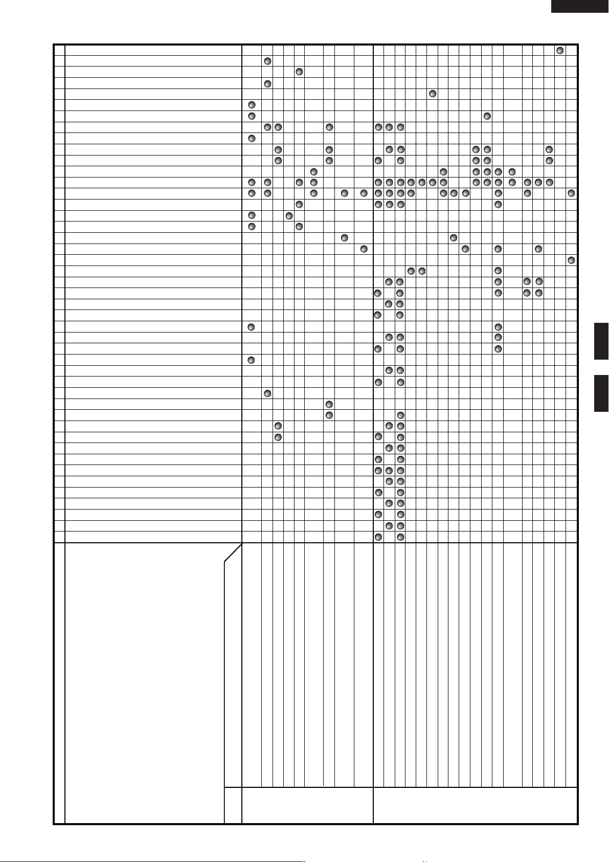
TROUBLESHOOTING GUIDE
When troubleshooting the microwave oven, it is helpful to follow the Sequence of Operation in performing the checks.
Many of the possible causes of trouble will require that a specific test be performed. These tests are given a procedure
letter which will be found in the “Test Procedure”section.
IMPORTANT: If the oven becomes inoperative because of a blown fuse F1 F10A (or F2 F10A) in the interlock switch
SW1 (or SW2) - monitor switches SW3 (or SW4) , check the interlock switch SW1 (or SW2) and monitor
switches SW3 (or SW4) before replacing the fuse F1 F10A (or F2 F10A).
10
Page 13
EEP ROM I-2
N KEY UNIT
TOUCH CONTROL TRANSFORMER T3
Due to programme lock
Over the max. cooking time
No power at wall outlet
HOME FUSE or BREAKER
Mis adjustment of switches
P FUSE 2.5A
O RELAY RY-4
O RELAY RY-3
O RELAY RY-1
M TOUCH CONTROL PANEL
Opened wire harness
Shorted wire harness
POWER SUPPLY CORD
K NOISE FILTER
OVEN LAMP OR SOCKET
J BLOWER MOTOR BM
J ANTENNA MOTORS SM
I EXHAUST THERMISTOR TH3
I MAGNETRON THERMISTOR (Lower) TH2
I MAGNETRON THERMISTOR (Upper) TH1
L HIGH VOLTAGE FUSE F5
L HIGH VOLTAGE FUSE F4
H EXHAUST TEMPERATURE FUSE TF3
H MAGNETRON TEMPERATURE FUSE TF2
H MAGNETRON TEMPERATURE FUSE TF1
F WEAK POINT F3
G FUSE F10A F2
G FUSE F10A F1
E STOP SWITCH SW5
E MONITOR SWITCH SW4
E MONITOR SWITCH SW3
E NTERLOCK SWITCH SW2
D INTERLOCK SWITCH SW1
D H.V. CAPACITOR C2
D H.V. CAPACITOR C1
H.V. WIRE HARNESS
C H.V. RECTIFIER ASSEMBLY FOR MG2
C H.V. RECTIFIER ASSEMBLY FOR MG1
B HIGH VOLTAGE TRANSFORMER T2 (Rear)
B HIGH VOLTAGE TRANSFORMER T1 (Front)
A MAGNETRON MG2 (Lower)
A MAGNETRON MG1 (Upper)
R-25AT
TESTPROCEDURE
AND
POSSIBLE CAUSE
DEFECTIVE PARTS
PROBLEM
. does not appear on display when power cord is plugged into
wall outlet.
Control panel can not accept key in.
Fuse F1 or F2 blows when the door is opened.
Home fuse blows when power cord is plugged into wall outlet.
Weak point F3 blows when power cord is plugged into wall outlet.
Oven lamp, fan motor and antenna motors do not work for 1
minute when the door is opened or after cooking.
Fuse F1 or F2 blows when power cord is plugged into wall outlet.
Oven lamp does not light when door is opened. (Blower and antenna
OFF
CONDITION
CONDITION
EE 1 (Magnetron MG1 failure)
EE 2 (Magnetron MG2 failure)
EE 3 (Magnetron MG1 and MG2 failure)
EE 6 (Exhaust thermistoropen)
EE 7 (Exhaust air temperature is high)
motors work)
Blower motor does not work when door is opened. (Oven lamp
lights and antenna motors work)
EE 9 (Exceeded max. heating time)
11
EE 16 (Thermistor of magnetron are open.)
EE 17 (Magnetron temperature is high.)
EE 19 (Magnetron thermistor short)
Oven lamp, blower motor and antenna motors do not work.
Oven lamp does not work.
Blower motor does not work.
Oven does not stop after end of cooking cycle.
Home fuse blows when starting the oven.
Oven goes into cook cycle but shuts down before end of cooking cycle.
It passed more than 1 minute after cooking but oven lamp, blower
motor and stirrer motors do not stop.
ON
CONDITION
EE 10 (Fault of memory)
Antenna motors do not work.
Page 14

R-25AT
TEST PROCEDURES
PROCEDURE
LETTER COMPONENT TEST
A MAGNETRON TEST
NEVER TOUCH ANY PART IN THE CIRCUIT WITH YOUR HAND OR AN INSULATED TOOL
WHILE THE OVEN IS IN OPERATION.
CARRY OUT
3D CHECKS.
Isolate the magnetron from high voltage circuit by removing all leads connected to filament terminal.
To test for an open circuit filament use an ohmmeter to make a continuity test between the magnetron
filament terminals, the meter should show a reading of less than 1 ohm.
To test for short circuit filament to anode condition, connect ohmmeter between one of the filament
terminals and the case of the magnetron (ground). This test should be indicated an infinite resistance.
If a low or zero resistance reading is obtained then the magnetron should be replaced.
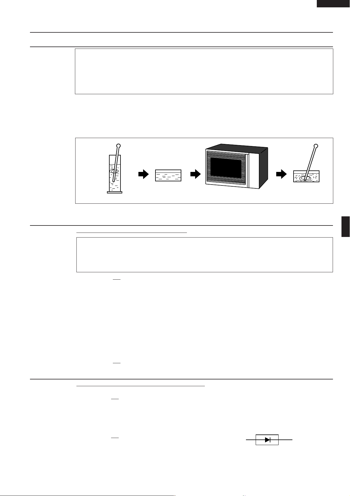
MICROWAVE OUTPUT POWER (1 litre water load)
The following test procedure should be carried out with the microwave oven in a fully assembled
condition (outer case fitted). Microwave output power from the magnetron can be measured by way
of IEC 60705, i.e. it is measured by how much power the water load can absorb. To measure the
microwave output power in the microwave oven, the relation of calorie and watt is used. When P(W)
heating works for t(second), approximately P x t/4.187 calorie is generated. On the other hand, if the
temperature of the water with V(ml) rises ∆T (°C) during this microwave heating period, the calorie of
the water is V x ∆T.
The formula is as follows;
P x t / 4.187 = V x ∆ T+ 0.55 x mc (T2-T0) P (W) = 4.187 x V x ∆T / t + 0.55 x mc (T2-T0)/t
Our condition for water load is as follows:
Room temperature (T0) ...... around 20°CPower supply Voltage .............. Rated voltage
Water load..................................... 1000 g Initial temperature (T1) ...................... 10±1°C
Heating time ................................. 20 sec. Mass of container (mc) ......................... 330 g
T2 ............... Final temperature P = 210 x ∆T+ 0.55 x mc(T2-T0)/20
Measuring condition:
1. Container
The water container must be a cylindrical borosilicate glass vessel having a maximum material
thickness of 3 mm and an outside diameter of approximately 190 mm.
2. Temperature of the oven and vessel
The oven and the empty vessel are at ambient temperature prior to the start the test.
3. Temperature of the water
The initial temperature of the water is (10±1)°C.
4. Select the initial and final water temperature so that the maximum difference between the final water
temperature and the ambient temperature is 5°C.
5. Select stirring devices and measuring instruments in order to minimize addition or removal of heat.
6. The graduation of the thermometer must be scaled by 0.1°C at minimum and be an accurate
thermometer.
7. The water load must be (1000±5) g.
8. “t” is measured while the microwave generator is operating at full power. Magnetron filament heatup time is not included.
NOTE: The operation time of the microwave oven is “t + 3” sec. (3 sec. is magnetron filament heat-up time.)
Measuring method:
1. Measure the initial temperature of the water before the water is added to the vessel.
(Example: The initial temperature T1 = 11°C)
2. Add the 1 litre water to the vessel.
3. Place the load on the centre of the shelf.
4. Operate the microwave oven at HIGH until the temperature of the water rises by a value ∆ T of
(10 ± 2) K.
5. Stir the water to equalize temperature throughout the vessel.
6. Measure the final water temperature. (Example: The final temperature T2 = 21°C)
7. Calculate the microwave power output P in watts from above formula.
12
Page 15
TEST PROCEDURES
B
C
HIGH VOLTAGE RECTIFIER
PROCEDURE
LETTER COMPONENT TEST
Room temperature ................................................................................................. T0 = 21°C
Initial temperature .................................................................................................. T1 = 11°C
Temperature after (20 + 3) = 23 sec ...................................................................... T2 = 21°C
Temperature difference Cold-Warm...................................................................... ∆T1 = 10˚C
Measured output power
The equation is “P = 210 x ∆T” ................................................ P = 210 x 10°C = 2100 Watts
JUDGMENT: The measured output power should be within the range of ± 15 % of the rated output
power.
CAUTION: 1°C CORRESPONDS TO 210 WATTS. REPEAT MEASUREMENT IF THE POWER IS
INSUFFICIENT.
1000g
R-25AT
1000g
T1˚C
Heat up for 23 sec.
B HIGH VOLTAGE TRANSFORMER TEST
WARNING: High voltage and large currents are present at the secondary winding and
filament winding of the high voltage transformer. It is very dangerous to work
near this part when the oven is on. NEVER make any voltage measurements
of the high-voltage circuits, including the magnetron filament.
CARRY OUT 3D CHECKS.
Disconnect the leads to the primary winding of the high voltage transformer. Disconnect the filament
and secondary winding connections from the rest of the HV circuitry. Using an ohmmeter, set on a low
range, it is possible to check the continuity of all three windings. The following readings should be
obtained:-
a. Primary winding approximately 1.2 Ω
b. Secondary winding approximately 75 Ω
c. Filament winding less than 1 Ω
1000g
T2˚C
If the readings obtained are not stated as above, then the high voltage transformer is probably faulty
and should be replaced.
CARRY OUT 4R CHECKS.
C HIGH VOLTAGE RECTIFIER ASSEMBLY TEST
CARRY OUT 3D CHECKS.
Isolate the high voltage rectifier assembly from the HV circuit. The high voltage rectifier can be tested
using an ohmmeter set to its highest range. Connect the ohmmeter across the terminal B+C of the high
voltage rectifier and note the reading obtained. Reverse the meter leads and note this second reading.
The normal resistance is infinite in one direction and more than 100 kΩ in the other direction.
CARRY OUT 4R CHECKS.
NOTE: FOR MEASUREMENT OF THE RESISTANCE OF THE RECTIFIER, THE BATTERIES OF
THE MEASURING INSTRUMENT MUST HAVE A VOLTAGE AT LEAST 6 VOLTS, BECAUSE
OTHERWISE AN INFINITE RESISTANCE MIGHT BE SHOWN IN BOTH DIRECTIONS.
13
Page 16

R-25AT
TEST PROCEDURES
PROCEDURE
LETTER COMPONENT TEST
D HIGH VOLTAGE CAPACITOR TEST
CARRY OUT 3D CHECKS.
A. Isolate the high voltage capacitor from the circuit.
B. Continuity check must be carried out with measuring instrument which is set to the highest
resistance range.
C. A normal capacitor shows continuity for a short time (kick) and then a resistance of about 10MΩ
after it has been charged.
D. A short-circuited capacitor shows continuity all the time.
E. An open capacitor constantly shows a resistance about 10 MΩ because of its internal 10MΩ
resistance.
F. When the internal wire is opened in the high voltage capacitor shows an infinite resistance.
G. The resistance across all the terminals and the chassis must be infinite when the capacitor is
normal.
If incorrect reading are obtained, the high voltage capacitor must be replaced.
CARRY OUT 4R CHECKS.
E SWITCH TEST
CARRY OUT 3D CHECKS.
Isolate the switch to be tested and using an ohmmeter check between the terminals as described in
the following table.
Table: Terminal Connection of Switch
Plunger Operation COM to NO COM to NC
Released Open circuit Short circuit
Depressed Short circuit Open circuit
If incorrect readings are obtained, make the necessary switch adjustment or replace the switch.
CARRY OUT 4R CHECKS.
F WEAK POINT F3 TEST
CARRY OUT 3D CHECKS.
If the weak point F3 is blown, there could be a shorts or grounds in electrical parts or wire harness.
Check them and replace the defective parts or repair the wire harness.
CARRY OUT 4R CHECKS.
CAUTION: Only replace weak point F3 with the correct value replacement.
G FUSE F1, F2 F10A TEST
CARRY OUT 3D CHECKS.
COM; Common terminal,
NO; Normally open terminal
NC; Normally close terminal
If the fuse F1 F10A (or F2 F10A) is blown when the door is opened, check the interlock switch SW1
(or SW2) and monitor switch SW3 (or SW4).
If thefuse F1 F10A (or F2 F10A) is blown by incorrect door switching replace the defective switch(s)
and the fuse F1 F10A (or F2 F10A).
CARRY OUT 4R CHECKS.
CAUTION: Only replace fuse F1 F10A (or F2 F10A) with the correct value replacement.
H TEMPERATURE FUSE TF1, TF2, TF3 TEST
1. CARRY OUT 3D CHECKS.
2. A continuity check across the temperature fuse terminals should indicate a closed circuit unless the
temperature of the temperature fuse reaches specfied temperature as shown below.
14
Page 17

TEST PROCEDURES
PROCEDURE
LETTER COMPONENT TEST
Open Close Display or
temperature temperature Condition Check point
Magnetron temperature fuse (Upper)
TF1
Magnetron temperature fuse
(Lower)
TF2
Exhaust temperature fuse
TF3
150˚C
120˚C
Non resetable
type
Non resetable
type
EE1
EE3
EE2
Oven shut
off
R-25AT
Magnetron
Test magnetron
MG1 Failure:
MG1 and Blower motor.
Magnetron MG1, MG2 Failure: Test magnetron MG1,
MG2. Check blower motor and ventilation opening.
Magnetron MG2 Failure:
Test magnetron
MG2 and Blower motor.
Food has been burned in oven.
Temperature of oven inside is very high.
3. CARRY OUT
4R CHECKS.
CAUTION: IF THE temperature fuse INDICATES AN OPEN CIRCUIT AT ROOM TEMPERATURE,
REPLACE temperature fuse.
I THERMISTOR TH1, TH2, TH3 TEST
1. CARRY OUT 3D CHECKS.
2. Follow the procedures below for each thermistor.
2-1. THERMISTOR TEST
Disconnect the connector of the thermistor from the switch harness. Measure the resistance of the
magnetron thermistor with an ohmmeter. Connect the ohmmeter leads to the leads of the thermistor.
Resistance: Approx. 500 kΩ -- 1 MΩ
If the meter does not indicate above resistance, replace the thermistor.
3. CARRY OUT 4R CHECKS.
J MOTOR WINDING TEST
CARRY OUT 3D CHECKS.
Disconnect the leads from the motor. Using an ohmmeter, check the resistance between the two
terminals.
Resistance of Blower motor should be approximately 60Ω.
Resistance of Antenna motor should be approximately 8.8 kΩ.
If incorrect readings are obtained, replace the motor.
CARRY OUT 4R CHECKS.
K NOISE FILTER TEST
CARRY OUT 3D CHECKS.
Disconnect the leads from the terminals of noise filter. Using an ohmmeter, check between the
terminals as described in the following table.
MEASURING POINT INDICATION OF OHMMETER
Between N and L Approx. 680 kΩ
Between terminal N and WHIT Short circuit
Between terminal L and BLK Short circuit
If incorrect readings are absorbed, replace the noise filter.
CARRY OUT 4R CHECKS.
L HIGH VOLTAGE FUSE F4, F5 TEST
CARRY OUT 3D CHECKS.
If the high voltage fuse F4 (or F5) is blown, there could be a short in the high voltage rectifier or the magnetron
MG1 (or MG2). Check them and replace the defective parts and the high voltage fuse F4 (or F5).
CARRY OUT 4R CHECKS.
CAUTION: Only replace high voltage fuse with the correct value replacement.
15
N
LINE CROSS CAPACITOR 0.22µF/ AC250V
LINE CROSS CAPACITOR
10000 pF/ AC250V
WHT
NOISE FILTER
F3 : WEAK POINT
NOISE SUPPRESSION COIL
DISCHARGE RESISTOR 680 kΩ 1/2W
DISCHARGE RESISTOR 10 MΩ 1/2W
LINE CROSS CAPACITOR
10000 pF/ AC250V
L
BLK
Page 18

R-25AT
TEST PROCEDURES
PROCEDURE
LETTER COMPONENT TEST
M TOUCH CONTROL PANEL ASSEMBLY TEST
The touch control panel consists of circuits including semiconductors such as LSI, IC, etc. Therefore,
unlike conventional microwave ovens, proper maintenance cannot be performed with only a voltmeter
and ohmmeter. In this service manual, the touch control panel assembly is divided into two units,
Control Unit and Key Unit, troubleshooting by unit replacement is described according to the symptoms
indicated.
1. Key Unit Note : Check key unit ribbon connection before replacement.
The following symptoms indicate a defective key unit. Replace the key unit.
a) When touching the pads, a certain pad produces no signal at all.
b) When touching the pads, sometimes a pad produces no signal.
2. Control Unit
The following symptoms may indicate a defective control unit. Replacing the control unit. Before
replacing the control unit, perform the key unit test (Procedure N) to determine if control unit is faulty.
2-1 Programming problems.
a) When touching the pads, a certain group of pads do not produce a signal.
2-2 Display problems.
a) For a certain digit, all or some segments do not light up.
b) For a certain digit, brightness is low.
c) Only one indicator does not light.
d) The corresponding segments of all digits do not light up; or they continue to light up.
e) Wrong figure appears.
f) A certain group of indicators do not light up.
g) The figure of all digits flicker.
2-3 Other possible problems caused by defective control unit.
a) Buzzer does not sound or continues to sound.
b) Cooking is not possible.
N KEY UNIT TEST
CARRY OUT
3D CHECKS.
If the display fails to clear when the STOP/CLEAR pad is depressed, first verify the flat ribbon cable
is making good contact, verify that the stop switch operates properly; that is the contacts are closed
when the door is closed and open when the door is open. If the stop switch is good, disconnect the flat
ribbon cable that connects the key unit to the control unit and make sure the stop switch is closed (either
close the door or short the stop switch connector ). Use the key unit matrix indicated on the control panel
schematic and place a jumper wire between the pins that correspond to the STOP/CLEAR pad making
momentary contact. If the control unit responds by clearing with a beep, the key unit is faulty and must
be replaced. If the control unit does not respond, it is faulty and must be replaced. If a specific pad does
not respond, the above method may be used (after clearing the control unit ) to determine if the control
unit or key pad is at fault.
CARRY OUT 4R CHECKS.
G9
G10
G11
G12
G1
G2 G G G5 G6 G7 G8
X
7
2
8
9
0
5
6
3
4
1
2
O RELAY TEST
CARRY OUT 3D CHECKS.
Remove the outer case and check voltage between Pin Nos. 3 and 5 of the connector (A) on the control
unit with an A.C. voltmeter. The meter should indicate 230 volts, if not check control unit circuity.
16
Page 19

TEST PROCEDURES
PROCEDURE
LETTER COMPONENT TEST
RY1, RY3 and RY4 Relay Test
These relays are operated by D.C. voltage.
Check voltage at the relay coil with a D.C. voltmeter during the microwave cooking operation.
DC. voltage indicated ............................. Defective relay.
DC. voltage not indicated ....................... Check diode which is connected to the relay coil. If
diode is good, control unit is defective.
RELAY SYMBOL OPERATIONAL VOLTAGE CONNECTED COMPONENTS
RY1 APPROX. 25.9V D.C. Oven lamp, Blower motor and Antenna motors
RY3 APPROX. 25.0V D.C. High voltage transformer (MG1)
RY4 APPROX. 25.0V D.C. High voltage transformer (MG2)
CARRY OUT 4R CHECKS.
P PROCEDURES TO BE TAKEN WHEN THE FUSE ON THE PRINTED WIRING BOARD(PWB) IS
OPEN
To protect the electronic circuits, this model is provided with a fine fuse added to the primary on the
PWB. If the fuse is open, follow the troubleshooting guide given below for repair.
R-25AT
Problem: POWER ON, indicator does not light up.
CARRY OUT 3D CHECKS.
STEPS OCCURRENCE CAUSE OR CORRECTION
1 The rated AC voltage is not present at Check supply voltage and oven power cord.
POWER terminal of CPU connector (CN-A).
2 The rated AC voltage is present at primary Touch control transformer or secondary circuit defective.
side of touch control transformer. Check and repair.
3 Fuse on the PWB is open. Replace the fuse with new one.
(CARRY OUT 3D CHECKS BEFORE REPAIR)
NOTE: *At the time of these repairs, make a visual inspection of the varistor for burning damage
and examine the transformer with tester for the presence of layer short-circuit (check
primary coil resistance). If any abnormal condition is detected, replace the defective parts.
CARRY OUT 4R CHECKS.
17
Page 20

R-25AT
TOUCH CONTROL PANEL ASSEMBLY
OUTLINE OF TOUCH CONTROL PANEL
The touch control section consists of the following units as
shown in the touch control panel circuit.
(1) Control Unit
(2) Key Unit
The principal functions of these units and the signals
communicated among them are explained below.
1. Control Unit
Signal of key touch and oven function control are all
processed by one microcomputer.
1) Power Supply Circuit
This circuit changes output voltage at the secondary
side of the touch control transformer to voltages required at each part by full wave rectifying circuit,
constant voltage circuit, etc..
2) Reset Circuit
This is an Auto-clear Circuit, i.e., a reset circuit, which
enables IC1 to be activated from initial state.
3) Power Synchronizing Signal Generating Circuit
This is a circuit for generating power synchronizing
signal by virtue of the secondary side output of touch
control transformer.
This signal is used for a basic frequency to time
processing and so on.
4) Clock Circuit
This is a circuit for controlling clock frequency required
for operating I-1.
5) I-1 (Main Processor)
This is a one-chip microcomputer, responsible for
controlling the entire control unit.
6) I-2 (Memory Processor)
This is a memory IC, responsible for memory function.
7) Display Circuit
This is a circuit for driving display tubes by I-1 output.
8) Key Input Circuit
This is a circuit for transmitting key input information to
I-1.
9) Sound-body Driving Circuit
This is a circuit for driving sound body by I-1 output.
10) Relay Driving Circuit
This is a circuit for driving output relay by I-1 output.
11) Stop Switch Circuit
This is a circuit for driving I-1 to detect door opening/
closing.
12) Exhaust Air Temperature Detecting Circuit
This is a circuit for transmitting output change of
thermistor (Exhaust thermistor) to I-1.
13) Magnetron Temperature Circuit.
(Detect Noload or Fan Lock)
This is a circuit for transmitting output change of
thermistor (Magnetron thermistor) to I-1.
2. Key Unit
The key unit is composed of a matrix circuit in which
when a key it touched, one of signals P33 - P34
generated by the LSI, is passed through the key and
returned to the LSI as one of signals P24 - P27. This
model has 20 Memory pads. When the oven is shipped,
Memory pad 1 to 10 are set as follows: fig.1.
Memory No. Cook Time Output Power
1 5 sec. 100%
2 10 sec. 100%
3 20 sec. 100%
4 30 sec. 100%
5 40 sec. 100%
6 50 sec. 100%
7 1 min. 100%
81 min.15 sec. 100%
91 min.30 sec. 100%
02 mins. 100%
(fig. 1)
This model has a double quantity pad. When the oven
is shipped, Magnification "1.8" is preset in the double
quantity pad. This model has an defrost pad. When the
oven is shipped, defrost is set as follows: fig.2.
1STAGE 2STAGE 3STAGE
POWER 40% 30% 10%
DEFROSTING TIME 0.2Tsec. 0.3T-20sec. 0.5T+20sec.
(fig. 2)
NOTE :
"CHECK" indicator will flash at half of defrosting time.
18
Page 21

DESCRIPTION OF LSI
LSI(IXA222DR)
The I/O signal of the LSI(IXA222DR) is detailed in the following table.
Pin No. Signal I/O Description
1 VCC IN Power source voltage: GND.
VC voltage of power source circuit input. Connected to GND.
2 VEE IN Anode (segment) of Fluorescent Display light-up voltage: -35V.
Vp voltage of power source circuit input.
3 AVSS IN Reference voltage input terminal.
A reference voltage applied to the A/D converter in the LSI. Connected to DC. (-5V)
4 VREF IN Reference voltage input terminal.
A reference voltage applied to the A/D converter in the LSI. Connected to GND.
5-6 AN7-AN6 IN Terminal to switch the specification.
7 AN5 IN Temperature measurement input: EXHAUST THERMISTOR
By inputting DC voltage corresponding to the temperature detected by the thermistor, this input is converted into temperature by the A/D converter built into the LSI.
8 AN4 IN Input signal which communicates the door open/close information to LSI.
Door closed; "H" level signal (0V).
Door opened; "L" level signal (-5.0V).
9 AN3 - Terminal not used.
10 AN2 IN Temperature measurement input: MAGNETRON THERMISTOR TH2.
By inputting DC voltage corresponding to the temperature detected by the thermistor, this input is converted into temperature by the A/D converter built into the LSI.
11 AN1 IN Temperature measurement input: MAGNETRON THERMISTOR TH1.
By inputting DC voltage corresponding to the temperature detected by the thermis-
tor, this input is converted into temperature by the A/D converter built into the LSI.
12 AN0 - Terminal not used.
13-14 P55-P54 - Terminal not used.
15 P53 OUT Magnetron (MG1) high-voltage circuit driving signal.
To turn on and off the cook relay. In 100% power level operation, "L" level during
cooking; "H" level otherwise. In other power level operation (90, 80, 70, 60, 50, 40,
30, 20, 10 or 0%), "H" and "L" level is repeated according to power level.
R-25AT
Power level ON OFF Power level ON OFF
100% 48sec. 0sec. 40% 22sec. 26sec.
90% 44sec. 4sec. 30% 16sec. 32sec.
80% 40sec. 8sec. 20% 12sec. 36sec.
70% 36sec. 12sec. 10% 8sec. 40sec.
60% 32sec. 16sec. 0% 0sec. 48sec.
50% 26sec. 22sec.
16 P52 - Terminal not used.
17 P51 OUT Magnetron (MG2) high-voltage circuit driving signal.
To turn on and off the cook relay. In 100% power level operation, "L" level during
cooking; "H" level otherwise. In other power level operation (90, 80, 70, 60, 50, 40,
30, 20, 10 or 0%), "H" and "L" level is repeated according to power level.
Power level ON OFF Power level ON OFF
100% 48sec. 0sec. 40% 22sec. 26sec.
90% 44sec. 4sec. 30% 16sec. 32sec.
80% 40sec. 8sec. 20% 12sec. 36sec.
70% 36sec. 12sec. 10% 8sec. 40sec.
60% 32sec. 16sec. 0% 0sec. 48sec.
50% 26sec. 22sec.
18 P50 - Terminal not used.
OFF
OFF
48 sec.
48 sec.
ON
ON
GND
-5V
GND
-5V
19
Page 22

R-25AT
Pin No. Signal I/O Description
19 P47 OUT Signal to sound buzzer.
This signal is to control the 2.5kHz
continuous signal.
A: Switch touch sound.
B: Guidance sound.
A
1.2 sec
B
0.12 sec
1.2 sec
GND
-5V
T
2.4 sec
C
C: Completion sound.
200 sec.
200 sec.
20-21 P46-P45 - Terminal not used.
22 P44 OUT Oven lamp, Blower motor and Antenna motor driving signal (Square Waveform
: 50Hz).
To turn on and off the shut-off relay (RY1).
During cooking
The Square waveform voltage is delivered
to the RY1 relay driving circuit and relays
(RY3, RY4, COOK RELAY) control circuit.
20 msec
23-24 P43-P42 - Terminal not used.
25 INT1 IN Signal synchronized with commercial power source frequency.
This is basic timing for all time processing of LSI.
OFF
H
L
GND
26 INT0 IN Connected to VC(-5) through pull-down resistor.
27 RESET IN Auto clear terminal.
Signal is input to reset the LSI to the initial state when power is supplied. Temporarily
set to "L" level the moment power is supplied, at this time the LSI is reset. Thereafter
set at "H" level.
28 P71 OUT Memory (EEPROM) clock output.
29 P70 IN/OUT Memory (EEPROM) data input/output.
30 XIN IN Internal clock oscillation frequency setting input.
The internal clock frequency is set by inserting the ceramic filter oscillation circuit with
respect to XOUT terminal.
31 XOUT OUT Internal clock oscillation frequency control output.
Output to control oscillation input of XIN.
32 VSS IN Power source voltage: -5V.
VC voltage of power source circuit input.
33 P27 IN Signal coming from touch key.
When either one of G-12 line keys on key matrix is touched, a corresponding signal
out of P30 - P34 will be input into P27. When no key is touched, the signal is held at
"L" level.
34 P26 IN Signal similar to P27.
When either one of G-11 line keys on key matrix is touched, a corresponding signal
will be input into P26.
35 P25 IN Signal similar to P27.
When either one of G-10 line keys on key matrix is touched, a corresponding signal
will be input into P25.
36 P24 IN Signal similar to P27.
When either one of G-9 line keys on key matrix is touched, a corresponding signal
will be input into P24.
37-40 P23-P20 OUT Segment data signal.
The relation between signals and indicators are as follows:
Signal Segment Signal Segment Signal Segment
P01 ..................... k P21 ......................... h P15 ..................... d
P02 ...................... j P20 ......................... g P14 ...................... c
P03 ...................... i P17 ......................... f P13 ..................... b
P23 .................. LB P16 ......................... e P12 ..................... a
P22 .................. UB
20 msec.
ON
-5V
20
Page 23

Pin No. Signal I/O Description
41-46 P17-P12 OUT Segment data signal.
Signal similar to P23..
47-48 P11-P10 OUT Digit selection signal.
The relation between digit signal and digit
are as follows:
Digit signal Digit
P11.................... 1st.
P10................... 2nd.
P07.................... 3rd.
P06.................... 4th.
P05.................... 5th.
P04.................... 6th.
Normally, one pulse is output in every ß
period, and input to the grid of the Fluorescent Display.
ß(50Hz)
ß(50Hz)
P11
P10
P07
P06
P05
P04
R-25AT
GND
-31(V)
H
L
GND
-31(V)
GND
-31(V)
49-52 P07-P04 OUT Digit selection signal.
Signal similar to P11.
53-55 P03-P01 OUT Segment data signal.
Signal similar to P23.
56 P00 - Terminal not used.
57-58 P37-P36 OUT (Sound) Voltage level control terminal.
This terminal (P37) is to control volume level of buzzer sound with terminals P36.
Since the volume level of buzzer sound depends on voltage energized, it is control
level in 3 steps by combining signal levels for P37 and P36. Relationship of signal
level combination to sound volume level is shown in the following table, 1~3 in the
table, however, are indicated in the descending order from the maximum level of
sound volume through the minimum level.
Sound Volume P36 P37
1, (Max.) L L
2, H L
3, (Min.) L H
*At Output terminal P47, rectangular wave signal of 2.5kHz is output.
59 P35 - Terminal not used.
60 P34 OUT Key strobe signal.
Signal applied to touch-key section. A pulse signal is input to P24 - P27 terminal while
one of G-4 line keys on key matrix is touched.
61 P33 OUT Key strobe signal.
Signal applied to touch-key section. A pulse signal is input to P24 - P27 terminal while
one of G-5 line keys on key matrix is touched.
62 P32 OUT Key strobe signal.
Signal applied to touch-key section. A pulse signal is input to P24 - P27 terminal while
one of G-6 line keys on key matrix is touched.
63 P31 OUT Key strobe signal.
Signal applied to touch-key section. A pulse signal is input to P24 - P27 terminal while
one of G-7 line keys on key matrix is touched.
64 P30 OUT Key strobe signal.
Signal applied to touch-key section. A pulse signal is input to P24 - P27 terminal while
one of G-8 line keys on key matrix is touched.
A : 1,(Max) 20V
A
2, 13V
3,(Min) 7V
21
Page 24

R-25AT
FUNCTIONAL DIAGRAM
E PROM
512 x 8
2
START
STOP
LOGIC
CONTROL
LOGIC
SLAVE ADDRESS
REGISTER
COMPARATOR
H.V. GENERATION
TIMING
& CONTROL
64
YDEC
8
DATA REGISTER
Dout
CK
3
1
5
64
XDEC
START CYCLE
INC
LOAD
WORD
ADDRESS
COUNTER
R/W
PIN
Dout
ACK
(6) SCL
(5) SDA
(4) Vss
(3) Vcc
2-2 Memory IC (I-2)
CAT24WC16P1 is a 4K-bit, serial memory, enabling CMOS to be erased/written electrically. This memory is constructed
with 512 registers x 8bits, enabling individual access, read and write operations to be performed. Details of input/output
signal for IC2 are as shown in the following diagram.
TOP VIEW
81
A0
A1
A2
VSS
VCC
TEST
72
SCL
63
SDA
54
Figure T-2. Relation between Pin Nos, and Signals
Pin No. Signal I/O Description
1-3 A0-A2 IN Connected to GND.
4 VSS IN Connected to VC(-5V).
5 SDA IN/OUT Serial data input/output : input/outputs data to I-1.
6 SCL IN Clock signal input : input/outputs serial data at every one pulse.
7 TEST IN Connected to VC(-5V).
8 VCC IN Connected to GND.
22
Page 25

SERVICING
R-25AT
1. Precautions for Handling Electronic Components
This unit uses CMOS LSI in the integral part of the
circuits. When handling these parts, the following
precautions should be strictly followed. CMOS LSI
have extremely high impedance at its input and output
terminals. For this reason, it is easily influenced by the
surrounding high voltage power source, static electricity charge in clothes, etc, and sometimes it is not fully
protected by the built-in protection circuit.
In order to protect CMOS LSI.
1) When storing and transporting, thoroughly wrap them
in aluminium foil. Also wrap all PW boards containing
them in aluminium foil.
2) When soldering, ground the technician as shown in the
figure and use grounded soldering iron and work table.
approx. 1M ohm
2. Shapes of Electronic Components
Transistor
E
B
C
KIA79L05P
DTB143ES
DTD143ES
KRA101M
3
2
1
Transistor
2SB953
C
E
Transistor
2SB1238
B
3. Servicing of Touch Control Panel
We describe the procedures to permit servicing of the
touch control panel of the microwave oven and the
precautions you must take when doing so. To perform
the servicing, power to the touch control panel is
available either from the power line of the oven itself or
from an external power source.
(1) Servicing the touch control panel with power supply of
the oven:
CAUTION: THE HIGH VOLTAGE TRANSFORMER
OF THE MICROWAVE OVEN IS STILL
LIVE DURING SERVICING PRESENTS
A HAZARD.
Therefore, when checking the performance of the
touch control panel, put the outer cabinet on the oven
to avoid touching the high voltage transformer, or
unplug the primary terminal (connector) of the high
voltage transformer to turn it off; the end of such
connector must be insulated with an insulating tape.
After servicing, be sure to replace the leads to their
original locations.
A. On some models, the power supply cord between the
touch control panel and the oven itself is so short that
the two can’t be separated. For those models, check
and repair all the controls (sensor-related ones included) of the touch control panel while keeping it
connected to the oven.
B. On some models, the power supply cord between the
touch control panel and the oven proper is long enough
that they may be separated from each other. For those
models, therefore, it is possible to check and repair the
controls of the touch control panel while keeping it
apart from the oven proper; in this case you must short
both ends of the door sensing switch (on PWB) of the
touch control panel with a jumper, which brings about
an operational state that is equivalent to the oven door
being closed. As for the sensor-related controls of the
touch control panel, checking them is possible if dummy
resistor(s) with resistance equal to that of the controls
are used.
(2) Servicing the touch control panel with power supply
from an external power source:
Disconnect the touch control panel completely from the
oven proper,and short both ends of the door sensing
switch (on PWB) of the touch control panel,which
brings about an operational state that is equivalent to
the oven door being closed. Connect an external
power source to the power input terminal of the touch
control panel, then it is possible to check and repair the
controls of the touch control panel it is also possible to
check the sensor-related controls of the touch control
panel by using the dummy resistor(s).
4. Servicing Tools
Tools required to service the touch control panel assembly.
1) Soldering iron: 30W
(It is recommended to use a soldering iron with a
grounding terminal.)
2) Oscilloscope: Single beam, frequency range: DC10MHz type or more advanced model.
3) Others: Hand tools
5. Other Precautions
1) Before turning on the power source of the control unit,
remove the aluminium foil applied for preventing static
electricity.
2) Connect the connector of the key unit to the control unit
being sure that the lead wires are not twisted.
3) After aluminium foil is removed, be careful that abnormal voltage due to static electricity etc. is not applied to
the input or output terminals.
4) Attach connectors, electrolytic capacitors, etc. to PWB,
making sure that all connections are tight.
5) Be sure to use specified components where high
precision is required.
23
Page 26

R-25AT
PROCEDURE FOR CHECKING/CLEARING SERVICE COUNTS OF MICROWAVE OVEN
The following procedure enables the servicer to obtain the
total service counts (cook cycles) for memory cooking,
manual, repeat, double quantity cooking and defrost. The
maximum capacity of the counter is 999,999 counts,
above which the counter will reset to "0". The counter will
retain the total counts (will not clear) in the event of a power
disruption.
1) Practice for checking total service counts
(eg; 234,567 Counts).
--- flashing / ---0.1sec. BUZZER
PAD DISPLAY INDICATOR LED PHONE
(door close) •
•
CHECK NUMBER • CHECK
CHECK #1 82 68 CHECK
(user total count)
#2
VOLUME
VOLUME
DOUBLE 2 34 56 7
QUANTITY (service total count)
1NUMBER 1
(after 1 sec.)
45
(filter used time)
2NUMBER 2
(after 1 sec.)
2 00
(filter lim. time)
0 (No 10) NUMBER 10
(after 1 sec.)
35 43 2
(service total cook time)
CHECK •
#1: Denotes total service counts within the reach of user,
of which checking and clearing practices are described in this instruction manual.
#2: Denotes the procedure for the servicer to disable
checking/clearing. This procedure is instructed to service personnel only and is excluded from the operation
manual.
2) Practice for clearing Service's counts
" " : Flicker / : 0.1 sec BUZZER
PAD ORDER DISPLAY PHONE
(Door close) •
CHECK "NUMBER" • CHECK
CHECK 82 68 "CHECK"
(User's Total Counts)
#1 VOLUME 82 68 "CHECK"
VOLUME 82 68 "CHECK"
DOUBLE QUANTITY 2 34 56 7 "CHECK"
(Total Counts Service)
SET 0 "CHECK"
00 "CHECK"
SET 0 "CHECK"
CHECK •
#1: Denotes the procedure for the servicer to disable
clearing. This procedure is instructed to service personnel only and is excluded from the operation manual.
PROCEDURE FOR ENTERING TO I-2
When the control unit or I-2 is exchanged, re-enter the
constants of EXPRESS DEFROST, the memory information
and the EEPROM data, referring to the following procedures.
If not so, the oven will not operate correctly.
1) How to enter the contents of DEFROST
T = STG1 + STG2 + STG3
Constants STG = A x T + B
of EXPRESS STG1 = 0.20 x T Power level 40%
DEFROST STG2 = 0.30 x T - 20 Power level 30%
STG3 = 0.50 x T + 20 Power level 10%
Suppose above constants are entered.
" " : Flicker / : 0.1 sec BUZZER
PAD ORDER DISPLAY PHONE
(Door close) •
SET •
SET "NUMBER" •
(within 2 sec.)
#1 START "NUMBER" •
EXPRESS
DEFROST
2,0 1 0.20 DEF x 2
MANUAL/ 1 0 DEF
REPEAT
MICROWAVE DEF "POWER"
POWER 1 0 100%
SETTING
41040%
MANUAL/ 2 0.00 DEF
REPEAT
3, 0 2 0.30 DEF x 2
MANUAL/ 2 0 DEF
REPEAT
MANUAL/ 2 - 0 DEF
REPEAT
22-20 DEF
MICROWAVE DEF "POWER"
POWER 2 -20 100%
SETTING
32-20 30%
MANUAL/ 3 0 DEF
REPEAT
#3 5 3 5 DEF
MICROWAVE DEF "POWER"
POWER 3 5 100%
SETTING
13510%
SET 4 • DEF
SET •
#1: No key entry signal.
#2: To set-B, touch the POWER SETTING key twice.
#3: Ex. "CHECK" will flash and the oven will beep after
50% of DEFROST time has lapsed when 5 key is
entered.
24
1 0.00 DEF
(A)
DEF POWER
(A)
(+ - B)
DEF POWER
DEF POWER
Page 27

2) How to enter the memory information
Example : Suppose cooking time 5 sec. and output power
100% are entered into the memory pad 1.
PAD ORDER DISPLAY PHONE
(Door close) •
SET •
SET "NUMBER" •
(within 2 sec.)
1 NUMBER 1 •
1
MANUAL/ NUMBER 1 • 0
REHEAT
5 NUMBER 1 • 5
SET "NUMBER" •
SET •
1
1
Enter the memory information into the memory pads 1 ~ 10
referring to above example. The memory information are
given below.
Memory No. Cook Time Output Power
1 5 sec. 100%
2 10 sec. 100%
3 20 sec. 100%
4 30 sec. 100%
5 40 sec. 100%
6 50 sec. 100%
7 1 min. 100%
81 min.15 sec. 100%
91 min.30 sec. 100%
10 2 mins. 100%
11-20 0 sec.
R-25AT
PAD ORDER DISPLAY PHONE
(Door close) •
SET •
SET "NUMBER" •
DOUBLE "NUMBER" • DOUBLE
CHECK "NUMBER" • DOUBLE
VOLUME "NUMBER" • DOUBLE
SET •
OTHER CHECKING AND CLEARING PROCEDURE FOR
1) To check the contents of defrost.
" " : Flicker / : 0.1 sec BUZZER
PAD ORDER DISPLAY PHONE
(Door close) •
CHECK "NUMBER" • CHECK
DEFROST 1 0.20 DEF CHECK
(A)
DEF CHECK
1 0 POWER
(+ - B) 40%
2 0.30 DEF CHECK
(A)
DEF CHECK
2 -20 POWER
(+ - B) 30%
DEF CHECK
3 5 POWER
10%
(Repeat)
CHECK •
#1: No key entry signal.
2) How to clear all counter(user and service) and total
cooking time and used time of filter.
25
Page 28

R-25AT
COMPONENT REPLACEMENT AND ADJUSTMENT PROCEDURE
WARNING: Avoid possible exposure to microwave energy. Please follow the instructions below before
operating the oven.
1. Disconnect the oven from power supply.
2. Make sure that a definite “click” can be heard when the
microwave oven door is unlatched. (Hold the door in a
closed position with one hand, then grip the door
handle and the door lever assembly with the other, this
causes the latch leads to rise, it is then possible to hear
a “click” as the door switches operate.)
3. Visually check the door and cavity face plate for damage (dents, cracks, signs of arcing etc.).
Carry out any remedial work that is necessary before
operating the oven.
Do not operate the oven if any of the following conditions
exist;
Please refer to ‘OVEN PARTS, CABINET PARTS, CONTROL PANEL PARTS, DOOR PARTS’, when carrying out any
of the following removal procedures:
1. Door does not close firmly.
2. Door hinge, support or latch hook is damaged.
3. The door gasket or seal is damaged.
4. The door is bent or warped.
5. There are defective parts in the door interlock system.
6. There are defective parts in the microwave generating
and transmission assembly.
7. There is visible damage to the oven.
Do not operate the oven:
1. Without the RF gasket (Magnetron).
2. If the wave guide or oven cavity are not intact.
3. If the door is not closed.
4. If the outer case (cabinet) is not fitted.
WARNING FOR WIRING
To prevent an electric shock, take the following
precautions.
1. Before wiring,
1) Disconnect the power supply cord.
2) Open the door and block it open.
3) Discharge the two high voltage capacitors and
wait for 60 seconds.
2. Don’t let the wire leads touch to the followiong parts;
1) High voltage parts:
Magnetron, High voltage transformer, High voltage capacitor, High voltage rectifier assembly and
High voltage fuse.
2) Hot parts:
Oven lamp, Magnetron, High voltage transformer,
3. Do not catch the wire leads in the outer case cabinet.
4. Insert the positive lock connector until its pin is locked
5. To prevent an error function, connect the wire leads
and Oven cavity.
3) Sharp edge:
Bottom plate, Oven cavity, Waveguide flange,
Chassis support and other metallic plate.
4) Movable parts (to prevent a fault)
Blower fan blade, Blower fan motor, Switches,
Switch levers, Antenna motors and Sirrer antennas.
and make sure that the wire leads do not come off
even if the wire leads are pulled.
correctly, referring to the Pictorial Diagram.
OUTER CASE, REAR CABINET AND POWER SUPPLY CORD REMOVAL
To remove the components, procedure as follows.
1. Disconnect oven from power supply.
2. Open the oven door and wedge it open.
3. Remove the screws from the rear and along side the
edge of the outer case.
4. Slide the case back about 1 inch (3 cm) to free it from
the oven cavity.
5. Lift entire case from the unit.
6. DISCHARGE TWO HIGH VOLTAGE CAPACITORS
BEFORE TOUCHING ANY OVEN COMPONENTS
OR WIRING.
7. Now, outer case is free.
N.B.; Step 1,2 and 9 form the basis of the 3D checks.
CAUTION:DISCHARGE TWO HIGH VOLTAGE CA-
PACITORS BEFORE TOUCHING ANY
OVEN COMPONENTS OR WIRING.
HIGH VOLTAGE TRANSFORMER(S) REMOVAL
1. CARRY OUT 3D CHECKS.
2. Remove the rear cabinet, too.
3. Disconnect wire lead(s) of high voltage transformer(s)
To remove rear cabinet and power supply cord:
8. Disconnect the power supply cord from the noise filter.
9. Remove the one (1) screws holding the grounding wire
of power supply cord to the oven cavity.
10.Remove the screws holding the rear cabinet to the
oven cavity and blower motor.
11.Remove the rear cabinet with the power supply cord
from the oven cavity.
12.Loosen the tab of the cord bushing, and remove the
power supply cord with the cord bushing from the rear
cabinet.
13.Remove the cord bushing from the power supply cord,
14.Now, the power supply cord and rear cabinet are free.
from magnetron(s).
4. Remove the wire lead(s) of high voltage transformer(s)
from the wire holder.
26
Page 29

R-25AT
5. Pull out the wire lead(s) of high voltage transformer(s)
from the tube.
6. Disconnect wire lead(s) of high voltage transformer(s)
from high voltage capacitor(s).
7. Disconnect the high voltage fuse(s) from high voltage
transformer(s).
MAGNETRON(S) REMOVAL
Removal
1. CARRY OUT 3D CHECKS.
2. Remove the rear cabinet, too.
3. Remove the two (2) screws holding magnetron exhaust duct to upper and lower waveguide.
4. Remove the magnetron exhaust duct from oven cavity.
5. Disconnect wire leads from magnetron(s ).
6. Disconnect magnetron thermistor from the connector
of the stop switch harness.
7. Remove the one (1) screw holding the thermistor angle
to the upper magnetron.
8. Remove the four (4) screws holding each magnetron to
MAGNETRON THERMISTOR REPLACEMENT
8. Disconnect the main wire harness from high voltage
transformer(s).
9. Remove two (2) screws holding each power transformer to base plate.
10.Remove the high voltage transformer(s) from base
plate.
12.Now, high voltage transformer(s) are free.
upper and/or lower waveguide. When removing the
screws, hold the magnetron to prevent it from falling.
9. Remove the magnetron(s) from upper and/or lower
waveguide with care so magnetron antenna is not hit
by any metal object around antenna.
10.Pull out the thermistor angle from the upper magnetron.
11.Now, the magnetron(s) is (are) free.
CAUTION: WHEN REPLACING MAGNETRON, BE
SURE THE R.F. GASKET IS IN PLACE AND
MOUNTING SCREWS ARE TIGHTENED
SECURELY.
Removal
1. CARRY OUT
3D CHECKS.
2. Remove the rear cabinet, too.
3.
Remove the magnetron from the waveguide flange,
referring to "MAGNETRON(S) REMOVAL".
4. Now, the magnetron with the magnetron thermistor
should be free.
5. Remove the thermistor angle from the magnetron by
pulling out.
6. Straighten the tab of the magnetron thermistor angle
holding the magnetron thermistor.
7. Remove the magnetron thermistor from the thermistor
angle.
8. Now, the magnetron thermistor is free.
Re-install
1. Install the magnetron thermistor to the thermistor angle
as shown in Figure C-1.
2. Hold the magnetron thermistor to the thermistor angle
by bending the tab of the thermistor angle.
3. Insert the thermistor angle between the 2nd. fin and
3rd. fin from the upper fin of the magnetron and push
it until the thermistor angle stops.
NOTE: The magnetron thermistor should be between the
upper fin and the 2nd. fin.
4. Re-install the magnetron to the waveguide flange with
four (4) screws.
5. Re-install the thermistor angle to the waveguide flange
with one (1) screw.
6. Re-install the magnetron exhaust duct to the upper and
lower waveguide flanges with two (2) screws.
7. Route the thermistor harness under the magnetron
temperature fuse.
8. Connect the thermistor harness to the stop switch
harness.
9. Connect the wire leads to the upper magnetron, referring to the pictorial diagram.
10.Re-install the power supply cord, rear cabinet and
outer case cabinet to the oven by reversing the procedures of "OUTER CASE, REAR CABINET AND
POWER SUPPLY CORD REMOVAL".
Upper magnetron
Upper fin
Thermistor
angle
Tab
Magnetron
thermistor
Figure C-1. Magnetron thermistor installation
HIGH VOLTAGE CAPACITOR, HIGH VOLTAGE FUSE AND HIGH VOLTAGE RECTIFIER
ASSEMBLY REMOVAL
1. CARRY OUT 3D CHECKS.
2. Remove the rear cabinet, too.
3. Remove two (2) screws holding earth side terminals of
high voltage rectifier assembly to the capacitor holder
and oven cavity.
4.
Disconnect all wire leads from the high voltage capacitor.
5. Disconnect high voltage fuse(s) from the high voltage
transformer(s). Now, high voltage fuse(s) is(are) free.
6.
Remove the three (3) screws holding the blower motor to
the top of oven cavity, the chassis support and air duct.
7. Disconnect high voltage wire lead(s) of the high voltage rectifier assembly from the magnetron(s).
Now, the the high voltage rectifier assembly is free.
8. Remove two (2) screws holding the capacitor holder to
oven cavity.
Now, the capacitors are free.
27
Page 30

R-25AT
CAUTION:
1. DISCHARGE THE TWO HIGH VOLTAGE CAPACITORS BEFORE TOUCHING ANY OVEN COMPONENTS OR WIRING.
2. DO NOT REPLACE ONLY THE HIGH VOLTAGE
RECTIFIER. IF IT IS DEFECTIVE, REPLACE THE
BLOWER MOTOR REMOVAL
1. CARRY OUT
2. Remove the rear cabinet, too.
3. Disconnect the wire leads from the blower motor and
noise filter.
4. Remove the one (1) screw holding the blower motor
angle to the oven cavity.
3D CHECKS.
STIRRER MOTORS (UPPER AND LOWER) REMOVAL
UPPER
1. CARRY OUT 3D CHECKS.
2. Disconnect the wire leads from the stirrer motor (upper).
3. Remove the one (1) screw holding the stirrer motor
(upper) to the oven cavity.
4. Turn and lift up the stirrer motor (upper).
5. Now, the stirrer motor (upper) is free.
LOWER
1. Disconnect oven from the power supply.
2. Remove the stirrer motor cover by snipping off the
HIGH VOLTAGE RECTIFIER ASSEMBLY.
3. WHEN REPLACING THE HIGH VOLTAGE RECTIFIER ASSEMBLY AND THE HIGH VOLTAGE CAPACITOR, THE CATHODE (EARTH) SIDE TERMINAL OF THE HIGH VOLTAGE RECTIFIER MUST BE
SECURED FIRMLY WITH A EARTHING SCREW.
5. Remove the one (1) screw holding the blower motor
angle to the chassis support.
6. Remove the one (1) screw holding the air duct to the
blower motor.
7. Remove the four (4) screws holding the blower motor
angle to the blower motor.
8. Now, the blower motor is free.
material in four portions.
3. Where the portions have been snipped off bend the
portions flat. No sharp edge must be evident after
removal of the stirrer motor cover.
4. Disconnect the wire leads from the stirrer motor (lower).
5. Remove the one (1) screw holding the stirrer motor
(Lower) to the oven cavity.
6. Now, the stirrer motor (lower) is free.
7. After replacement use one (1) screw to fit the stirrer
motor cover. (This screw has been fitted to the base
plate near the stirrer motor cover beforehand.)
HOW TO RELEASE THE POSITIVE LOCK® CONNECTOR.
Procedure
1. CARRY OUT 3D CHECKS.
2. Pushing the lever of positive lock® connector, pull down
the connector from the terminal.
3. Now, the connector is free.
CAUTION: WHEN CONNECTING THE POSITIVE
LOCK® CONNECTORS TO THE TERMINALS, CONNECT THE POSITIVE LOCK
CONNECTOR SO THAT THE LEVER
FACES YOU.
OVEN LAMP AND LAMP SOCKET REMOVAL
1. CARRY OUT 3D CHECKS.
2. Remove the oven lamp.
3. Pull the wire leads from the oven lamp socket by
pushing the terminal hole of the oven lamp socket with
the small flat type screw driver.
4. Lift up the oven lamp socket .
5. Now, the oven lamp socket is free.
Terminal
Positive lock®
connector
Lever
®
1
Push
2
Pull down
Figure C-2. How to release the positive lock connector.
Oven lamp
socket
Terminal
Wire lead
Terminal hole
Flat type small
screw driver
Figure C-3. Oven lamp socket
TERMINAL INSULATOR REPLACEMENT
1. Open covers of the terminal insulator by using small flat
type screw driver.
2. Remove the receptacle from the terminal insulator.
3. Now, the terminal insulator is free.
28
Page 31

R-25AT
Installation
1. Insert the receptacle into terminal insulator.
Terminal
insulator
Flat type
screw driver
CONTROL PANEL ASSEMBLY AND CONTROL UNIT REMOVAL
CONTROL PANEL ASSEMBLY REMOVAL
The complete control panel should be removed for replacement of components. To remove the control panel,
proceed as follows:
1. Disconnect the oven from power supply.
2. Wait for 60 seconds to discharge the high voltage
capacitor.
3. Remove the air intake filter assembly from the base
plate.
4. Remove two (2) screws holding the control panel to the
base plate.
5. Pull down the control panel and remove it forward.
6. Disconnect connectors and wire leads from the control
unit.
7. Now the control panel assembly is free.
CAUTION FOR TOUCH CONTROL PANEL REMOVAL
1) Hold the lower end (Position A, Fig. 1) of the touch
control panel assembly firmly while sliding it down and
toward you.
2) If the Touch Control Panel is hard to remove;
(1) Insert a flat head screw driver into space B . (Fig. 1)
(2) Rotate the screwdriver clockwise while holding posi-
tion C of the Touch Control Panel. (Fig. 2)
TO AVOID DAMAGE TO TOUCH CONTROL PANEL,
COVER THE TIP OF SCREWDRIVER WITH TAPE.
Fig. 1
TOUCH CONTROL PANEL
SCREW DRIVER
B
B
A
C
Fig. 2
2. Close covers of the terminal insulator, as shown
illustlated below.
COVERS
RECEPTACLE
Replacement of individual component is as follows:
CONTROL UNIT AND CONTROL PANEL FRAME
(WITH KEY)
8. Remove three (3) screws holding the control panel
mounting angle to the panel frame.
9. Lift up the control panel mounting angle from the
panel frame.
10.Disconnect connector (G) from the control unit by
pushing the hooks of cable holder inwardly.
11.Remove four (4) screws holding the control unit to
the panel frame assembly.
12.Now, the control unit and control panel frame (with
key) are free.
CAUTION:
At installing control panel unit assembly to main
body set:
1. Ensure the installation of wiring-related parts
without negligence.
2. When inserting key cable to main body set,
ensure them free from caught-in trouble. In
addition, when installing the control panel assembly to base plate with screws, be sure of
pushing the control panel unit upward to fix with
screws firmly.
3. Do not allow any wire leads to come near the
varistor works, because it will explode and the
wire leads near by the varistor will be damaged.
HOW TO ATTACH MEMBRANE SWITCH AND
GRAPHIC SHEET
1. Before attaching a new membrane switch and graphic
sheet, remove remaining adhesive on the control panel
frame surfaces completely with a soft cloth soaked in
alcohol.
2. Attach the graphic sheet to the membrane switch, with
adjusting their upper edges and right edges. (This
assembly part is called key unit in the following.)
NOTE : When attaching the graphic sheet, make sure
that air does not come between the membrane
switch and the graphic sheet.
3. Then, adjust the upper edge and right edge of the key
unit to the lower edge of the display window and the
right flange of the control panel frame.
4. Stick the key unit firmly to the control panel frame by
rubbing with soft cloth to prevent scratching.
POWER SUPPLY CORD REPLACEMENT
1. CARRY OUT 3D CHECKS
2. Release the cord bushing from the rear cabinet.
3. Disconnect the brown and blue wires of the power
supply cord from the noise filter.
4. Remove the single (1) screw holding the earth wire of
power supply cord.
29
Page 32

R-25AT
5. Remove the power supply cord.
Re-install
1. Insert the power supply cord into the cord bushing.
2. Connect the brown and blue wires of power supply cord
into the terminals of noise filter, referring to pictorial
diagram.
3. Install the green/yellow wire of power supply cord with
the one (1) screw.
4. Re-install the cord bushing to the rear cabinet.
5. CARRY OUT
4R CHECKS.
INTERLOCK SWITCHES, MONITOR SWITCHES, AND STOP SWITCH REMOVAL
1. CARRY OUT 3D CHECKS.
2. Remove the control panel from the oven cavity referring to “CONTROL PANEL REMOVAL”.
3. Remove the two (2) screws holding the latch hook to
the oven cavity.
4. Open the door and pull the latch hook out of the oven
cavity.
5. For stop switch removal
5-1. Disconnect the wire leads from the switch.
5-2. Push the retaining tabs outward slightly and then
pull the switch forwards and remove it from the
latch hook.
Power supply cord
Cord bushing
Noise filter
Green/Yellow
wire
Screw
Brown wire
L
N
Blue wire
Figure C-4. Power supply cord replacement
6. For interlock or monitor switches removal
6-1. Disconnect the wire leads from the interlock or
monitor switches.
6-2. Remove the single (1) screw and nut holding the
interlock or monitor switches to the latch hook.
CAUTION: IF THE LATCH HOOK IS NEW, WHEN
THE INTERLOCK SWITCHES OR MONITOR SWITCHES ARE INSTALLED, THE
TWO (2) TABS OF THE LATCH HOOK
SHOULD BE BROKEN.
INTERLOCK SWITCHES, MONITOR SWITCHES, AND STOP SWITCH ADJUSTMENT
In case interlock switches, stop switch and monitor switches
do not operate properly due to a mis-adjustment, the
following adjustment should be made.
1. Loosen the two (2) screws holding the latch hook.
2. With the door closed, adjust the latch hook by moving
it back and forward, or up and down. In and out play of
the door allowed by the latch hook should be less than
0.5mm. The vertical position of the latch hook should
be placed where the stop switch and interlock switches
have activated with the door closed.
The horizontal position of the latch hook should be
placed where the monitor switches have activated with
the door closed.
3. Secure the screws with washers firmly.
4. Make sure of the interlock switches, stop switch, and
monitor switches operation. If those switches have not
activated with the door closed, loose two (2) screws
holding latch hook and adjust the latch hook position.
After adjustment, make sure of the following:
1. In and out play of door remains less than 0.5mm when
in the latched position.
2. The stop switch and interlock switches interrupt the
circuit before the door open when the door release
lever is pulled, and then and monitor switch close the
circuit when the door is opened.
3. Re-install outer case and check for microwave leakage
around the door with an approved microwave survey
meter. (Refer to Microwave Measurement Procedure.)
Figure C-5 Latch Switch Adjustments
Door release
lever
Joint lever
Head lever
Latch head
Latch head
Latch hook
SW4: Monitor switch
SW3: Monitor switch
SW2: Interlock switch
SW1: Interlock switch
SW5: Stop switch
(Oven side)
(Oven side)
REMOVAL
1. CARRY OUT 3D CHECKS.
DOOR REPLACEMENT AND ADJUSTMENT
2. Remove the two (2) screws holding each of the upper
and lower oven hinges to the oven cavity.
30
Page 33

R-25AT
3. Remove door assembly with upper and lower oven
hinges by pulling it forward.
4. Release upper and lower oven hinges from door assembly.
5. Now, door assembly is free.
NOTE: When individual parts are replaced, refer to "Door
Disassembly".
RE-INSTALL
1. Insert the upper and lower oven hinges into door hinge
pins.
2. Insert the upper and lower oven hinges with door
assembly into rectangular holes of oven cavity front
plate.
3. Make sure that the door is parallel with oven face lines
(left and upper side line) and door latch heads pass
through the latch holes correctly.
4. Fasten upper and lower oven hinges firmly to oven
cavity with two (2) screws on each hinge.
Note: After any service to the door;
(A) Make sure that interlock switches, stop switch
and monitor switches are operating properly.
(Refer to chapter "Test Procedures".).
(B) An approved microwave survey meter should be
used to assure compliance with proper microwave radiation emission limitation standards.
2. Deviation of the door alignment from horizontal line of
cavity face plate is to be less than 1.0mm.
3. The door is positioned with its face depressed toward
the cavity face plate.
4. Re-install outer case and check for microwave leakage
around door with an approved microwave survey meter. (Refer to Microwave Measurement Procedure.)
Note: The door on a microwave oven is designed to act
as an electronic seal preventing the leakage of
microwave energy from oven cavity during cook
cycle. This function does not require that door be
air-tight, moisture (condensation)-tight or lighttight. Therefore, occasional appearance of moisture, light or sensing of gentle warm air movement
around oven door is not abnormal and do not of
themselves, indicate a leakage of microwave energy from oven cavity. If such were the case, your
oven could not be equipped with a vent, the very
purpose of which is to exhaust the vapor-laden air
from the oven cavity.
UPPER
OVEN HINGE
OUTER CASE
CABINET
DOOR ADJUSTMENT
When removing and/or loosening hinges such as in door
replacement, the following adjustment criteria are taken.
Door adjustment is performed with the door properly
installed and closed and while the oven hinges are loose.
1. Loosen upper and lower oven hinges with phillips head
screw driver.
2. Adjust the door by moving it vertically so that the top
right hand corner of the door is in line with the top of the
control panel frame assembly.
3. Tighten the upper and lower oven hinge screws.
After adjustment, make sure of the following:
1. Door latch heads smoothly catch the latch hook through
the latch holes, and the latch head goes through the
center of the latch hole.
DOOR DISASSEMBLY
CHOKE COVER REMOVAL
1. Open the door and insert a putty knife (thickness of
about 0.5mm) in gap between the choke cover and
corner portion of door panel to free engaging parts.
Refer to Fig. C-7.
NOTE: As the choke cover and door panel are engage at
16 places, do not force any perticular part.
2. Remove the choke cover carefully. (If choke cover is
broken, replace with a new one.)
DOOR
HANDLE
PUTTY KNIFE
CHOKE COVER
2
UPPER
OVEN HINGE
CHOKE COVER
1
BENT
LOWER
OVEN HINGE
LATCH HEAD
Figure C-7. Choke cover
PUTTY KNIFE
BENT
DOOR PANEL
FRONT
LOWER
OVEN HINGE
LATCH
HEADS
Figure C-6. Door Replacement
DOOR COMPONENTS REMOVAL
UPPER AND LOWER OVEN HINGES REMOVAL
1. Remove the door assembly from oven cavity, referring to "REMOVAL" of "DOOR REPLACEMENT AND
ADJUSTMENT".
2. Remove choke cover, referring to "CHOKE COVER
REMOVAL".
3. Release the oven hinges from the door panel.
4. Now, the oven hinges are free.
DOOR HANDLE REMOVAL
1. Remove the door assembly from oven cavity, "REMOVAL" of "DOOR REPLACEMENT AND ADJUSTMENT".
2. Place door assembly on a soft cloth with latches
facing up.
3. Remove choke cover from door panel, referring to
"CHOKE COVER REMOVAL".
4. Remove two (2) screws holding the door handle to
door.
31
Page 34

R-25AT
5. Remove the door handle from door panel.
6. Now, door handle is free.
UPPER AND LOWER LATCH HEADS REMOVAL
7. Remove the door release lever from the door assembly.
8. Remove the three (3) screws holding the joint plate to
the door panel.
9. Release the latch spring from the tab of the joint lever
and joint plate.
10.Release the latch heads from joint lever and joint plate.
11.Now, the latch heads are free.
DOOR CASE REMOVAL
1. Remove the door assembly from oven cavity, referring
to "REMOVAL" of "DOOR REPLACEMENT AND ADJUSTMENT".
2. Remove choke cover from door panel, referring to
"CHOKE COVER REMOVAL".
3. Remove door handle from door panel, referring to
"DOOR HANDLE REMOVAL".
4. Bend up four (4) nails of door case.
5. Remove door case from door panel.
6. Now, the door case is free.
DOOR GLASS REMOVAL
7. Remove the four (4) screws holding two (2) outside
window fixing plates to door panel.
8. Now, the door glass is free.
SERVICE INFORMATION
IMPORTANT: When the magnetron MG1 and/or MG2 is replacing, the relays (RY3 and RY4) on control unit must
be replaced at the same time. Because if the magnetron's life has been over, the relay's life may
also be over.
32
Page 35

MICROWAVE MEASUREMENT
R-25AT
After adjustment of door latch switches, monitor switch
and door are completed individually or collectively, the
following leakage test must be performed with a survey
instrument and it must be confirmed that the result meets
the requirements of the performance standard for microwave oven.
REQUIREMENT
The safety switch must prevent microwave radiation emission in excess of 5mW/cm2 at any point 5cm or more from
external surface of the oven.
PREPARATION FOR TESTING:
Before beginning the actual test for leakage, proceed as
follows;
1. Make sure that the test instrument is operating normally as specified in its instruction booklet.
Important:
Survey instruments that comply with the requirement
for instrumentations as prescribed by the performance
standard for microwave ovens must be used for testing.
Recommended instruments are:
NARDA 8100
NARDA 8200
HOLADAY HI 1500
SIMPSON 380M
2. Place the oven tray into the oven cavity.
3. Place the load of 275 ± 15ml of water initially at 20
± 5˚C in the centre of the oven tray. The water
container should be a low form of 600 ml beaker with
inside diameter of approx. 8.5cm and made of an
electrically non-conductive material such as glass
or plastic.
The placing of this standard load in the oven is important not only to protect the oven, but also to insure that
any leakage is measured accurately.
4. Close the door and turn the oven ON with the timer set
for several minutes. If the water begins to boil before
the survey is completed, replace it with 275ml of cool
water.
5. Move the probe slowly (not faster that 2.5cm/sec.)
along the gap.
6. The microwave radiation emission should be measured at any point of 5cm or more from the external
surface of the oven.
mW cm
mW cm
2
2
Microwave leakage measurement at 5 cm distance
33
Page 36

R-25AT
TEST DATA AT A GLANCE
Parts Symbol Value / Data
Fuse F1 F10A
Fuse F2 F10A
Weak point F3 A017
High voltage fuse F4, F5 0.75A 5kV
Temperature fuse (Upper Mag.) TF1 150˚C
Temperature fuse (Lower Mag.) TF2 150˚C
Temperature fuse(Exhaust) TF3 120˚C
Magnetron thermistor (Upper) TH1 Approx. 500kΩ - 1MΩ at the room temperature
Magnetron thermistor (Lower) TH2 Approx. 500kΩ - 1MΩ at the room temperature
Exhaust thermistor TH3 Approx. 500kΩ - 1MΩ at the room temperature
Oven lamp OL 250V 25W
High voltage capacitor C1 1.07µF AC 2300V
High voltage capacitor C2 1.07µF AC 2300V
High voltage transformer T1, T2 Filament winding < 1Ω
Secondary winding Approx. 75Ω
Primary winding Approx. 1.2Ω
Magnetron MG1 Filament winding < 1Ω
Filament winding - chassis ∞ Ω
Magnetron MG2 Filament winding < 1Ω
Filament winding - chassis ∞ Ω
WARNING: DISCONNECT THE PLUG WHEN MEASURING RESISTANCE.
34
Page 37

R-25AT
SW2:
INTERLOCK SWITCH
SW5:
STOP
SWITCH
CN-A
CN-A
F1 : WEAK POINT A017
BLU
NEUTRAL LIVE
GRN/YLW
BRN
NOISE FILTER
SW1:
INTERLOCK SWITCH
SW3:
MONITOR
SWITCH
SW4: MONITOR SWITCH
NOISE SUPPRESSION COIL
DISCHARGE RESISTOR 680 k‰ 1/2W
DISCHARGE RESISTOR 10 M‰ 1/2W
LINE CROSS CAPACITOR 0.22 F/ AC250V
LINE BYPASS CAPACITOR
10000 pF/ AC250V
LINE BYPASS CAPACITOR
10000 pF/ AC250V
T3:
TOUCH CONTROL
TRANSFORMER
FUSE
2.5A
F2: FUSE F10A
TF1: TEMP. FUSE 150¡C
(Upper Mag.)
TF3: EXHAUST
TEMP. FUSE
120¡C
TF1:
TEMP. FUSE 150¡C
(Lower Mag.)
CONTROL
UNIT
230V~50Hz
H. V. RECTIFIER
C1: H.V. CAPACITOR
1.07 F/ AC2300V
C2: H.V. CAPACITOR
1.07 F/ AC2300V
MG1: MAGNETRON (Upper)
F1: FUSE F10A
H. V. RECTIFIER
MG2: MAGNETRON (Lower)
RY1
EARTH
F4:
H.V.FUSE
0.75 A
F5:
H.V.FUSE
0.75 A
L
N
1
3
6
5
4
3
2
1
5
4
3
2
1
5
RY4:
COOK RELAY
RY3:
COOK RELAY
TH3:
EXHAUST
THERMISTOR
TH1:
MAGNETRON
THERMISTOR
(Upper)
TH2:
MAGNETRON
THERMISTOR (Lower)
T1: HIGH VOLTAGE
TRANSFORMER
(Front)
OVEN LAMP
ANTENNA
MOTOR
SM
SM
BM
T2: HIGH VOLTAGE
TRANSFORMER
(Rear)
OL
NOTE: CONDITION OF OVEN
SCHEMATIC
1. POWER SUPPLY CONNECTED AND/OR 1MINUTE
AFTER DOOR CLOSED OR COOK OFF.
2. . APPEAR ON DISPLAY.
NOISE FILTER
L
BRN
230V~50Hz
EARTH
BLU
GRN/YLW
NEUTRAL LIVE
NOISE SUPPRESSION COIL
F1 : WEAK POINT A017
DISCHARGE RESISTOR 680 k‰ 1/2W
LINE CROSS CAPACITOR 0.22 F/ AC250V
10000 pF/ AC250V
LINE BYPASS CAPACITOR
DISCHARGE RESISTOR 10 M‰ 1/2W
10000 pF/ AC250V
LINE BYPASS CAPACITOR
N
T3:
TOUCH CONTROL
TRANSFORMER
5
CN-A
TEMP. FUSE
120¡C
TF3: EXHAUST
NOTE: Indicates components with potential above 250 V.
TF1: TEMP. FUSE 150¡C
3
FUSE
2.5A
CONTROL
UNIT
RY1
CN-A
1
OL
OVEN LAMP
RY4:
COOK RELAY
RY3:
COOK RELAY
SM
SM
ANTENNA
MOTOR
6
5
4
SW5:
3
STOP
2
SWITCH
1
TH3:
EXHAUST
THERMISTOR
5
4
3
2
TH1:
1
MAGNETRON
THERMISTOR
(Upper)
BM
BLOWER
MOTOR
SW2:
INTERLOCK SWITCH
(Upper Mag.)
TF1:
TEMP. FUSE 150¡C
(Lower Mag.)
SW3:
MONITOR
SWITCH
SW4: MONITOR SWITCH
TH2:
MAGNETRON
THERMISTOR (Lower)
F1: FUSE F10A
F2: FUSE F10A
(Front)
T1: HIGH VOLTAGE
TRANSFORMER
(Rear)
T2: HIGH VOLTAGE
TRANSFORMER
C1: H.V. CAPACITOR
1.07 F/ AC2300V
F4:
H.V.FUSE
0.75 A
C2: H.V. CAPACITOR
1.07 F/ AC2300V
F5:
H.V.FUSE
0.75 A
MG1: MAGNETRON (Upper)
H. V. RECTIFIER
MG2: MAGNETRON (Lower)
H. V. RECTIFIER
NOTE: CONDITION OF OVEN
SCHEMATIC
1. FOR 1MINUTE AFTER DOOR CLOSED.
2. . APPEAR ON DISPLAY.
Figure O-2 Oven Schematic-IDLE Condition (Door opened condition)
SW1:
INTERLOCK SWITCH
Figure O-1 Oven Schematic-OFF Condition
35
Page 38

R-25AT
NOTE: CONDITION OF OVEN
SCHEMATIC
1. DOOR CLOSED.
2. MANUAL/ REPEAT KEY TOUCHED.
3. COOKING TIME PROGREMMED.
4. START PAD TOUCHED.
NOISE FILTER
L
BRN
230V~50Hz
BLU
NEUTRAL LIVE
NOISE SUPPRESSION COIL
F1 : WEAK POINT A017
EARTH
GRN/YLW
DISCHARGE RESISTOR 680 k‰ 1/2W
LINE CROSS CAPACITOR 0.22 F/ AC250V
N
T3:
TOUCH CONTROL
TRANSFORMER
10000 pF/ AC250V
LINE BYPASS CAPACITOR
DISCHARGE RESISTOR 10 M‰ 1/2W
CN-A
10000 pF/ AC250V
LINE BYPASS CAPACITOR
TF3: EXHAUST
NOTE: Indicates components with potential above 250 V.
TF1: TEMP. FUSE 150¡C
(Upper Mag.)
TF1:
TEMP. FUSE 150¡C
(Lower Mag.)
SW3:
MONITOR
SWITCH
SW4: MONITOR SWITCH
TH2:
MAGNETRON
THERMISTOR (Lower)
F1: FUSE F10A
F2: FUSE F10A
FUSE
CONTROL
RY1
CN-A
5
TEMP. FUSE
120¡C
3
2.5A
UNIT
1
OL
OVEN LAMP
RY4:
COOK RELAY
RY3:
SM
SM
ANTENNA
MOTOR
6
5
4
SW5:
3
STOP
2
SWITCH
1
COOK RELAY
TH3:
EXHAUST
THERMISTOR
5
4
3
2
TH1:
1
MAGNETRON
THERMISTOR
(Upper)
BM
SW2:
INTERLOCK SWITCH
SW1:
INTERLOCK SWITCH
(Front)
C1: H.V. CAPACITOR
T1: HIGH VOLTAGE
TRANSFORMER
F4:
H.V.FUSE
0.75 A
(Rear)
C2: H.V. CAPACITOR
T2: HIGH VOLTAGE
TRANSFORMER
F5:
H.V.FUSE
0.75 A
1.07 F/ AC2300V
MG1: MAGNETRON (Upper)
H. V. RECTIFIER
1.07 F/ AC2300V
MG2: MAGNETRON (Lower)
H. V. RECTIFIER
Figure O-3 Oven Schematic-Cooking Condition
36
Page 39

R-25AT
BRN
NOISE FILTER
BLU
NL
SW5 : STOP
SWITCH
TOUCH CONTROL PANEL
CN-C
3
6 GRN
2
4
5
1 ORG
NO
COM.
BLU
GRN
GRN
ORG
WHT
COM.
NO
SW1: INTERLOCK
SWITCH
(Cabinet side)
COM.
NO
COM.
NC
BRN
BLU
HIGH VOLTAGE COMPONENTS
MG1 :
MAGNETRON
(Upper)
White case
Black tape
MG2 :
MAGNETRON
(Lower)
T1 :
HIGH VOLTAGE
TRANSFORMER
F4: H.V. FUSE
F5: H.V. FUSE
H. V. RECTIFIER
C2 : HIGH VOLTAGE
CAPACITOR
BLK
WHT
OL : OVEN LAMP
& SOCKET
CONNECTOR
TH3:
EXHAUST
THERMISTOR
G/Y
POWER
SUPPLY
CORD
EARTH
NEUTRAL
LIVE
BLK
WHT
SW3 :
MONITOR
SWITCH
(Cabinet side)
CN-A
CN-A
CN-B
4
1 BLK
5 YLW
3 RED
2
5 BLK
1 GRN
3 GRY
2 RED
4
BM :BLOWER
MOTOR
CN-B
GRN
BLU
COM.
NC
BRN
BLU
SW4 :
MONITOR
SWITCH
(Oven side)
BLU
BLU
RED
RED
RED
BRN
WHT
WHT
WHT
SW2: INTERLOCK
SWITCH
(Oven side)
YLW
WHT
ORG
ORG
BLU
SM:
ANTENNA
MOTOR
(Upper)
BLK
BLK
RED
WHT
BLK
T2 :
HIGH VOLTAGE
TRANSFORMER
C1 : HIGH VOLTAGE
CAPACITOR
H. V. RECTIFIER
TH1:
MAGNETRON
THERMISTOR (Upper)
TH2:
MAGNETRON
THERMISTOR (Lower)
BLK
BLK
WHT
BLK
W
H
T
W
H
T
B
L
K
B
L
K
O
R
G
O
R
G
F1 : FUSE F10A
(Cabinet side)
(Blue case) (Blue case)
(Blue case)
(Blue case)
(Blue case)
(Blue case)
(Blue case)
(Blue case)
(Blue case)
(Blue case)
(Blue case)
(Blue case)
(Blue case)
(Blue case)
BLU
F2 : FUSE F10A
(Oven side)
Blue
case
TF1: TEMP. FUSE 150ßC
(Upper MAG.)
TF3: EXHAUST TEMP.
FUSE 120ßC
BRN
BLK
TF1: TEMP. FUSE 150ßC
(Lower MAG.)
BRN
BLK
1
2
RED
GRN
1
2
GRY
GRN
1
2
WHT
GRN
RED
SM:
ANTENNA
MOTOR
(Lower)
TOUCH CONTROL
TRANSFORMER
CN-D
CN-D
RY1
BZ
1
1
1
1
112
5
6
8
RY4
F1: FUSE 2.5A
ORG
RED
YLW
WHT
1
2
3
4
5
6
7
8
BLU
BRN
BLK
WHT
A017
WHT
WHT
RY3
CN-C
CN-G
I-1
I-2
5
BRN
BRN
BRN
A
B
C
1
2345 6
A
B
C
D
E
F
G
D
E
Figure S-1. Pictrorial Diagram
F
G
H
123456
37
H
Page 40

R-25AT
47
44
46
48
49
50
51
52
53
54
55
56
57
58
59
60
61
62
63
64
P45
P44
P43
P42
INT1
INT0
RESET
P71
P70
XIN
XOUT
VSS
32
31
30
29
28
27
26
25
24
23
22
21
P30
P31
P32
P33
P34
P35
P36
P37
P00
P01
P02
P03
P04
P05
P06
P07
P10
P11
P12
P13
M1
COM
3
4
1
2
6
5
8
7
A0
A1
A2
VSS
VCC
TEST
SCL
SDA
I-2
D1D2
D3 D4
3
2
1
Q3
RY3
RY1
CN-A
C30
R33
R31
10K
2G
3G
4G
5G
6G
i
j
k
NP
F2
F2
f
e
d
a
1G
OL
AC2
AC1
b
c
10
11
12
P27
P26
P25
P24
P23
P22
P21
P20
P17
P16
P15
41
43
42
40
39
38
37
36
35
34
33
P46
P47
P50
P51
P52
P53
P54
P55
AN0
AN1
AN2
AN3
AN4
AN5
AN6
AN7
VREF
AVSS
VEE
3
1
2
4
5
6
7
8
9
10
11
12
13
14
15
16
17
18
19
20
P14
45
CP
F1
F1
NC
CP
F1
F1
9
R95
R96
R97
R98
4.7 K
R94
R92
R90
R91
4.7 K
D7
10EDB10
C1
C2
50V/0.1uF
50V/2200uF
R1
1.5 K
Q11
2SB953
ZD1
HZ16-1
C3
C8
16V/100uF
50V/10uF
C4
C5
50V/10uF
C10
ZD2
HZ4C3
Q2
KRA101M
R5
10K
C7
D6
D5
10EDB10
C74
C9
50V/10uF
R2
270/1W
R21
56K
C21
KRA101M
Q20
P1
S1
S2
S2
S1
P2
Q80 C80
D81
C81
Q81
M2
COM
RY4
D83
D84
10EDB10
D70
D71
100
R70
R71
4.7 K
C70
J2J1
15K
R67
2
3
4
5
6
7
8
1
CF1
J4
J3
C98
C99
C100
C101
330Px4
g
h
UB
NC
LB
50V/
0.1u F
R3
1W
150
50V/0.1uF
50V/0.1uF
R41
20K
Q40
KRA101M
Q41
2SB1238
BZ
6G
R42
R43
39K
10K
C31
R30
100
DTB143ES
Q86
Q87
R65
R64
4.7K x3
C60
C62
C63
R60
R62
R63
33K
1.1
K
1.1
K
CN-C
CN-G Key Unit
4.7 K
4.7 K
4.7 K
4.7 K
4.7 K
4.7 K
4.7 K
CN-B
CN-D
DU24D1-1PR(M)
VC
5
4
3
2
1
C6
50V/0.1uF
I-1
F1
1
5
3
4
5
6
7
8
3
2
1
23
24
25
22
BLACK
R22
4.7K
C22
C75
CAT24WC16PI
VC
Door
4
5
6
3
2
1
IXA222DR
:IF NOT SPECIFIED 0.01uF/16V
:IF NOT SPECIFIED 1/4W ±5%
RED
Oven
TH
MG.
TH2
MG.
TH1
* I-1
P00 - P23 PULL DOWN
P24 - P27 PULL DOWN
CST4.00MGW
4.7K
50V/10uF
VCC
26
25
24
23
22
21
20
19
18
17
16
15
14
13
12
11
10
9
8
7
6
5
4
3
2
1
DEF CHECK
POWER
%
DOUBLEON
NUMBER
1
2
3
FILTER
DG1
A053DR
FLUORESCENT DISPLAY TUBE
R40
3.3K
R93
R32
2.7K
10EDB10
KIA79L05P
D1 - D4: 10EDB10
50V/0.1uF
DTD143ES
50V/10uF
KRA101M
VRS1
470V
FTR-F3AA024E
2.5A
RTRNPA005WRZZ
DU24D1-1PR(M)
DTB143ES
aa a a
a
j
j
h
h
i
j
k
b
c
b
c
d
d
e
e
g
g
f
f
5G
4G
3G
2G
1G
:IF NOT SPECIFIED 1SS133
1
A
B
C
D
E
F
G
H
2345 6
A
B
C
D
E
Figure S-2. Control Panel Circuit
F
G
H
123456
38
Page 41

R-25AT
1
A
B
C
2345 6
A
B
C
D
E
D
E
RED
F
BLACK
2.5A
F
FUSE
G
G
H
H
Figure S-4. Printed Wiring Board
123456
39
Page 42

R-25AT
PARTS LIST
Note: The parts marked "∆" may cause undue microwave exposure.
The parts marked "*" are used in voltage more than 250V.
REF. NO. PART NO. DESCRIPTION Q'TY CODE
ELECTORIC PARTS
BM FMOTEA482WRKZ Blower motor 1 BH
C1, C2 RC-QZA320WRZZ High voltage capacitor 2 AV
*
F1,F2 QFS-CA026WRZZ Fuse F10A 2 AH
F3 QFS-CA017WRE0 Weak point A017 1 AF
F4,F5 QFS-IA002WRE0 High voltage fuse 0.75A/ 5kV 2 AQ
*
MG1 RV-MZA322WREZ Magnetron (Upper) 1 BB
∆
*
MG2 RV-MZA322WREZ Magnetron (Lower) 1 BB
∆
*
OL RLMPTA028WRE0 Oven lamp 1 AK
SM RMOTDA238WRZZ Antenna motor 2 AR
SW1 QSW-MA085WRE0 Interlock switch 1 AF
SW2 QSW-MA085WRE0 Interlock switch 1 AF
SW3 QSW-MA086WRE0 Monitor switch 1 AF
SW4 QSW-MA086WRE0 Monitor switch 1 AF
SW5 QSW-MA085WRE0 Stop switch 1 AF
T1, T2 RTRN-A599WRE0 High voltage transformer 2 BM
*
T3 RTRNPA005WRZZ Touch control transformer 1 AQ
TF1 QFS-TA014WRE0 Temperature fuse 150C (Upper magnetron) 1 AG
TF2 QFS-TA014WRE0 Temperature fuse 150C (Lower magnetron) 1 AG
TF3 QFS-TA015WRE0 Temperature fuse 120C (Exhaust) 1 AG
TH1 FH-HZA070WRE0 Magnetron thermistor (Upper) 1 AM
TH2 FH-HZA070WRE0 Magnetron thermistor (Lower) 1 AM
TH3 FH-HZA070WRE0 Exhaust thermistor 1 AM
1- 1 FACCVA013WRK0 Power supply cord 1 BG
1- 2 QSOCLA024WRE0 Oven lamp socket 1 AH
1- 3 FW-QZA117WRK0 High voltage rectifier assembly 1 AU
*
1- 4 FPWBFA335WRE0 Noise filter 1 AX
1- 5 QFSHDA019WRE0 Fuse holder 2 AH
CABINET PARTS
2- 1 GDAI-A353WRTZ Base plate 1 BB
2- 2 GCABUA860WRPZ Outer case cabinet 1 BD
2- 3 GCOVAA283WRW0 Rear cabinet 1 AX
2- 4 FFTASA064WRY0 Oven lamp access cover assembly 1 AN
2- 4-1 PCUSUA585WRPZ Cushion 1 AF
2- 4-2 PREFHA059WRP0 Reflector 1 AF
2- 5 FFPF-A016WRK0 Vibration-proof sheet 1 AU
2- 6 PSHEGA007WRE0 Rubber sheet B 2 AE
CONTROL PANEL PARTS
3- 1 DPWBFC365WRKZ Control unit 1 BN
3- 1A QCNCMA314DRE0 5-pin connector (CN-A) 1 AC
3- 1B QCNCMA413DRE0 6-pin connector (CN-B) 1 AC
3- 1C QCNCMA420DRE0 5-pin connector (CN-C) 1 AK
3- 1D QCNCMA493DRZZ 6-pin connector (CN-D) 1 AE
3- 1E QCNCWA030DRE0 12-pin connector (CN-G) 1 AF
3- 1F RV-KXA053DRE0 Fluorescent display tube 1 AW
3- 1G PCUSGA359WRP0 Cushion 2 AC
BZ RALM-A014DRE0 Buzzer (PKM22EPT) 1 AG
C1 VCKYD11HF104Z Capacitor 0.1uF 50V 1 AB
C2 VCEAG51HW228M Capacitor 2200uF 50V 1 AH
C3 VCEAG31HW106M Capacitor 10uF 50V 1 AB
C4 VCKYD11HF104Z Capacitor 0.1uF 50V 1 AB
C5 VCEAG31HW106M Capacitor 10uF 50V 1 AB
C6-7 VCKYD11CY103N Capacitor 0.01uF 16V 2 AA
C8 VCEAG31CW107M Capacitor 100uF 16V 1 AC
C9 VCEAG31HW106M Capacitor 10uF 50V 1 AB
C10 VCKYD11HF104Z Capacitor 0.1uF 50V 1 AB
C21 VCKYD11HF104Z Capacitor 0.1uF 50V 1 AB
C22 VCKYD11CY103N Capacitor 0.01uF 16V 1 AA
C30 VCKYD11CY103N Capacitor 0.01uF 16V 1 AA
C31 VCEAG31HW106M Capacitor 10uF 50V 1 AB
C60 VCKYD11CY103N Capacitor 0.01uF 16V 1 AA
C62-63 VCKYD11CY103N Capacitor 0.01uF 16V 2 AA
C70 VCKYD11CY103N Capacitor 0.01uF 16V 1 AA
C74 VCKYD11HF104Z Capacitor 0.1uF 50V 1 AB
C75 VRD-B12EF472J Resistor 4.7k ohm 1/4W 1 AA
C80 VCKYD11HF104Z Capacitor 0.1uF 50V 1 AB
C81 VCEAG31HW106M Capacitor 10uF 50V 1 AB
C98-101 VCKYD11HB331K Capacitor 330pF 50V 4 AA
CF1 RCRS-A010DRE0 Ceramic seronator (CST4.00MGW) 1 AD
D1-7 VHD10EDB10+-1T Diode (10EDB10) 7 AB
D70 VHD10EDB10+-1T Diode (10EDB10) 1 AB
D71 VHD1SS133//-2 Diode (1SS133) 1 AA
40
Page 43

REF. NO. PART NO. DESCRIPTION Q'TY CODE
D81 VHD1SS133//-2 Diode (1SS133) 1 AA
D83-84 VHD1SS133//-2 Diode (1SS133) 2 AA
F1 QFS-IA001KKZZ Fuse 2.5A 50V 1 AD
I- 1 RH-IXA222DRZZ LSI 1 AU
I- 2 VHICAT24W16-1 EEPROM 1 AF
Q2 VSKRA101M//-3 Transistor (KRA101M) 1 AB
Q3 VHIKIA79L05-3 Transistor (KIA79L05P) 1 AE
Q11 VS2SB953-PQ-4 Transistor (2SB953) 1 AG
Q20 VSKRA101M//-3 Transistor (KRA101M) 1 AB
Q40 VSKRA101M//-3 Transistor (KRA101M) 1 AB
Q41 VS2SB1238//-3 Transistor (2SB1238) 1 AA
Q80 VSKRA101M//-3 Transistor (KRA101M) 1 AB
Q81 VSDTD143ES/-3 Transistor (DTD143ES) 1 AC
Q86-87 VSDTB143ES/-3 Transistor (DTB143) 2 AC
R1 VRD-B12EF152J Resistor 1.5k ohm 1/4W 1 AA
R2 VRS-B13AA271J Resistor 270 ohm 1W 1 AA
R3 VRS-B13AA151J Resistor 150 ohm 1W 1 AA
R5 VRD-B12EF103J Resistor 10k ohm 1/4W 1 AA
R21 VRD-B12EF563J Resistor 56k ohm 1/4W 1 AA
R22 VRD-B12EF472J Resistor 4.7k ohm 1/4W 1 AA
R30 VRD-B12EF101J Resistor 100 ohm 1/4W 1 AA
R31 VRD-B12EF153J Resistor 15k ohm 1/4W 1 AA
R32 VRD-B12EF272J Resistor 2.7k ohm 1/4W 1 AA
R33 VRD-B12EF103J Resistor 10k ohm 1/4W 1 AA
R40 VRD-B12EF332J Resistor 3.3k ohm 1/4W 1 AA
R41 VRD-B12EF203J Resistor 20k ohm 1/4W 1 AA
R42 VRD-B12EF393J Resistor 39k ohm 1/4W 1 AA
R43 VRD-B12EF103J Resistor 10k ohm 1/4W 1 AA
R60 VRD-B12EF333J Resistor 33k ohm 1/4W 1 AA
R62-63 VRD-B12EF112J Resistor 1.1k ohm 1/4W 2 AA
R64-65 VRD-B12EF472J Resistor 4.7k ohm 1/4W 2 AA
R67 VRD-B12EF472J Resistor 4.7k ohm 1/4W 1 AA
R70 VRD-B12EF101J Resistor 100 ohm 1/4W 1 AA
R71 VRD-B12EF472J Resistor 4.7k ohm 1/4W 1 AA
R90-98 VRD-B12EF472J Resistor 4.7k ohm 1/4W 9 AA
RY1 RRLY-B004MRE0 Relay (FTR-F3AA024E) 1 AF
RY3-4 RRLY-A113DRE0 Relay (DU24D1-1PR(M)) 2 AM
VRS1 VHV10V471K+-1 Varistor (TNR10V471K) 1 AD
ZD1 VHEHZ161///-1 Zener diode (HZ16-1) 1 AA
ZD2 VHEHZ4C3///-1 Zener diode (HZ4C3) 1 AA
3- 2 FPNLCB774WRKZ Control panel frame with key unit assembly 1 BD
3- 2-1 PSHEPA963WREZ Graphic sheet 1 AS
3- 2-2 QSW-KA041DRZZ Membrane switch 1 AV
3- 2-3 HDECAA195WRP0 Decoration metal fittings 1 AP
3- 2-4 PCUSUA451WRP0 Cushion 1 AB
3- 2-5 PCUSGA618WREZ Cushion 1 AD
3- 3 LANGTA243WRW0 Control panel mounting angle 1 AF
3- 4 XEPSD30P10XS0 Screw : 3mm x 10mm 4 AA
3- 5 XEPSD40P12000 Screw : 4mm x 12mm 2 AA
3- 6 XHTSD40P08RV0 Screw : 4mmx 8mm 1 AA
OVEN PARTS
4- 1 PCLICA042WREZ Chassis clip 4 AC
4- 2 FDUC-A345WRY0 Exhaust duct assembly 1 AP
4- 3 FOVN-A444WRY0 Oven cavity 1 BS
∆
4- 4 PFILWA053WRP0 Oven light screen (Inside) 1 AE
4- 5 MLEVPA153WRF0 Switch lever A 1 AC
4- 6 MLEVPA154WRF0 Switch lever B 1 AC
4- 7 MLEVPA155WRF0 Switch lever C 1 AC
4- 8 MSPRCA075WRE0 Switch spring A 1 AB
4- 9 MSPRCA076WRE0 Switch spring B 2 AB
4-10 PHOK-A081WRF0 Latch hook 1 AP
∆
4-11 MHNG-A216WRM0 Lower oven hinge 1 AG
∆
4-12 PCUSUA626WREZ Cushion 1 AC
4-13 PCUSU0407WRP0 Cushion 2 AA
4-14 FGLSPA063WRY0 Ceramic shelf 1 BF
4-15 FPLT-A008WRY0 Stirrer antenna upper assembly 1 AV
4-16 FPLT-A009WRY0 Stirrer antenna lower assembly 1 AV
4-17 PCUSUA538WRPZ Cushion 1 AD
4-18 LANGQA370WRP0 Oven lamp mounting plate 1 AD
4-19 LBNDKA068WRP0 Capacitor holder 1 AD
4-20 PGIDHA054WRW0 Water-proof cover 1 AF
4-21 NSFTPA031WRF0 Antenna motor shaft 2 AH
4-22 PZETEA087WRPZ Insulater 1 AE
4-23 PCUSUA417WRP0 Cushion 1 AB
∆
4-24 MHNG-A215WRM0 Upper oven hinge 1 AG
4-25 PCUSUA413WRP0 Cushion 1 AG
4-26 PCUSUA415WRP0 Cushion 1 AC
R-25AT
41
Page 44

R-25AT
Note: The parts marked "∆" may cause undue microwave exposure.
The parts marked "*" are used in voltage more than 250V.
REF. NO. PART NO. DESCRIPTION Q'TY CODE
4-27 PDUC-A729WRF0 Air duct 1 AL
4-28 PDUC-A564WRW0 Mg exhaust duct 1 AP
4-29 PCUSUA414WRP0 Cushion 1 AD
4-30 LANGKA679WRPZ Fixing angle S 1 AD
4-31 HDECQA147WRM0 Corner cap right 1 AE
4-32 LANGFA195WRW0 Chassis support 1 AH
4-33 LBSHCA012WRE0 Cord bushing 1 AD
4-34 FCOVPA032WRKZ Stirrer cover assembly 1 BF
4-35 FFIL-A005WRK0 Air intake filter assembly 1 AS
4-36 HDECEA001WRP0 Decoration sash 1 AR
4-37 HDECQA146WRM0 Corner cap left 1 AE
4-38 PCUSGA409WRP0 Cushion 2 AE
4-39 LANGQA440WRM0 Earth angle 1 AE
4-40 LANGQA512WRP0 Thermistor angle 2 AE
4-41 LANGQA593WRPZ Blower motor angle 1 AH
4-42 MSPRCA101WRE0 Switch lever spring C 1 AC
4-43 PCUSUA268WRP0 Cushion 1 AA
DOOR PARTS
5 DDORFA850WRK0 Door assembly 1 BV
∆
5- 1 FDORFA289WRT0 Door panel assembly 1 BH
∆
5- 2 GCOVAA242WRY0 Door case 1 BD
5- 3 FHNDMA011WRY0 Door lever assembly 1 AP
5- 4 GCOVHA350WRF0 Choke cover 1 AR
5- 5 JHNDMA039WRM0 Door handle 1 AX
5- 6 LANGKA766WRP0 Outside window fixing plate 2 AF
5- 7 PCUSGA430WRP0 Cushion 2 AM
5- 8 PGLSPA457WRE0 Door glass 1 AV
5- 9 PPACGA142WRP0 Door case packing 2 AF
5-10 PSHEPA428WRE0 Sealer film 1 AF
5-11 PGID-0024WRF0 Handle guide 4 AC
5-12 XFPSD40P08K00 Screw : 4mm x 8mm 3 AA
5-13 XHTSD40P08RV0 Screw : 4mm x 8mm 4 AA
5-14 FANGKA200WRY0 Latch fixing angle 1 AQ
5-15 FLEVFA019WRY0 Joint lever 1 AP
5-16 LSTPCA002WRM0 Latch head 2 AM
∆
5-17 MLEVPA220WRF0 Head lever 1 AM
5-18 MSPRCA097WRE0 Latch spring 1 AG
5-19 HBDGCA113WREZ Door badge 1 AF
5-20 PGID-0025WRF0 Handel spacer 1 AC
5-21 PCUSGA486WRP0 Cushion 1 AM
5-22 PSPA-A102WRE0 Door case spacer 2 AE
5-23 XBPSD40P10K00 Screw : 4mm x 10mm 2 AA
MISCELLANEOUS
6- 1 TINSMA018WRRZ Operation manual 1 AR
6- 2 TLABHA029WRR0 Menu sticker 1 AC
6- 3 FW-VZB999WREZ Switch harness 1 AP
6- 4 FW-VZC001WREZ Main wire harness 1 BC
6- 5 LHLDWA040WRE0 Wire holder A 1 AB
6- 6 LBNDKA079WRE0 Wire holder 2 AB
6- 7 TCAUHA168WRR0 H caution label 1 AH
6- 8 TCAUHA257WRR0 S caution sheet 1 AE
6- 9 PZET-A018WRE0 Terminal insulator 2 AC
6-10 TLABSA064WRR0 A017 label 1 AC
6-11 TLABSA055WRR0 Fuse label F10A 2 AE
SCRE,NUTS AND WASHERS
7- 1 LX-BZA131WREZ Special screw 4 AB
7- 2 LX-BZA138WREZ Special screw 2 AB
7- 3 XHTSD40P08RV0 Screw : 4mm x 8mm 14 AA
7- 4 XONSC40P10000 Screw : 4mm x 10mm 1 AA
7- 5 XOTSC40P12000 Screw : 4mm x 12mm 5 AA
7- 6 XOTWW40P08000 Screw : 4mm x 8mm 5 AB
7- 7 LX-BZA116WRE0 Special screw 2 AD
7- 8 XOTWW40P10000 Screw : 4mm x 10mm 11 AB
7- 9 XOTSD40P12000 Screw : 4mm x 12mm 6 AA
7-10 LX-CZA038WRE0 Special screw 3 AA
7-11 LX-EZA004WRE0 Special screw 2 AA
7-12 LX-BZA041WRE0 Special screw 2 AA
7-13 XJPSD40P10000 Screw : 4mm x 10mm 2 AA
7-14 LX-EZA042WRE0 Special screw 12 AB
7-15 XOTSD40P10RV0 Screw : 4mm x 10mm 3 AA
7-16 LX-BZA064WRE0 Special screw 1 AA
7-17 LX-WZA035WRE0 Special washer 1 AB
42
Page 45

R-25AT
REF. NO. PART NO. DESCRIPTION Q'TY CODE
7-18 XWSSD40-10000 Washer: 4mm x 1mm 1 AA
7-19 XFTSD40P12000 Screw : 4mm x 12mm 1 AA
7-20 LX-BZA150WREZ Special screw 1 AB
7-21 XCHWW40P08000 Screw : 4mm x 8mm 2 AB
7-22 XCPSD30P10000 Screw : 3mm x 10mm 2 AA
7-23 XBPSD30P28KS0 Screw : 3mm x 28mm 2 AA
7-24 XNESD30-24000 Nut : 3mm x 2.4mm 2 AA
7-25 XCPWW30P08000 Screw : 3mm x 8mm 2 AA
7-26 LX-BZA132WRZZ Special screw 4 AB
7-27 XOTSD40P08000 Screw : 4mm x 8mm 4 AA
HOW TO ORDER REPLACEMENT PARTS
To have your order filled prompty and correctly, please furnish the following information.
1. MODEL NUMBER 2. REF. NO. 3. PART NO. 4. DESCRIPTION
PACKING AND ACCESSORIES
DOOR PROTECTION SHEET
SPADPA552WRE0
DOOR PAD
SPADF0341WRE0
TRAY SUPPORT
SPADPA551WRE0
6-1 OPERATION MANUAL
TOP PAD ASSEMBLY
FPADBA313WRK0
WRAP COVER
SSAKH0111WRE0
BOTTOM PAD ASSEMBLY
FPADBA314WRK0
PACKING CASE
SPAKCE007WREZ
* Not replaceable items.
43
Page 46

R-25AT
1
2345 6
OVEN AND CABINET PARTS
A
7-4
2-4
2-4-1
2-2
7-5
7-2
4-30
4-20
4-23
2-3
2-4-2
B
7-6
4-43
TH3
7-3
7-14
A
2
A
B
7-13
7-6
4-25
7-14
7-3
1-1
TF1
1
7-15
TH1
D
C
C1
7-14
C2
6-6
7-6
7-8
4-26
4-2
2-5
7-25
C
TF3
SM
4-38
7-9
7-1
1-2
OL
D
4-18
x2
7-13
7-3
4-21
7-3
4-37
4-24
4-3
4-4
7-1
4-11
E
4-15
TF2
4-27
4-19
B
TH2
4-12
7-2
4-40
4-40
7-3
1-3
7-3
7-8
7-8
A
1
A
2
7-8
7-8
4-13
MG1
MG2
7-21
7-16
F1
4-28
F2
7-8
7-22
1-5
6-7
7-15
7-12
4-33
7-8
7-10
7-8
7-8
4-29
4-32
1-1
7-18
7-17
4-39
4-13
A
B
7-19
C
D
E
7-27
6-6
4-22
1-4
6-18
7-3
F3
6-10
F
4-36
7-26
4-21
SM
F
7-3
7-3
7-11
4-31
7-24
7-14
T1
7-14
7-3
4-9
F4
F5
4-8
SW4
SW3
4-5
7-27
7-23
4-41
C
D
4-42
4-6
SW2
4-16
7-20
T3
4-34
2-1
4-9
4-10
T2
4-7
SW5
7-23
SW1
BM
4-17
G
H
7-7
4-35
2-6
4-1
7-9
7-9
7-10
7-3
4-1
6-5
4-14
4-1
2-6
7-10
4-1
G
H
123456
44
Page 47

R-25AT
Actual wire harness may be different from illustration.
6-4
6-3
5
3-6
3-4
3-5
3-3
3-2-3
3-2
3-2-2
3-1
3-2-4
3-2-5
3-2-1
5-15
5-16
5-17
5-18
5-4
5-23
5-12
5-10
5-22
5-14
5-1
5-9
5-8
5-7
5-6
5-13
5-13
5-2
5-20
5-11
5-11
5-5
5-19
5-6
5-21
5-3
6-9
1
A
B
2345 6
CONTROL PANEL PARTS
A
B
C
DOOR PARTS
C
D
D
MISCELLANEOUS
E
F
E
F
G
H
123456
45
G
H
Page 48

R-25AT
COPYRIGHT © 2003 BY SHARP CORPORATION
ALL RIGHTS RESERVED.
No part of this publication may be reproduced, stored in
retrieval systems, or transmitted in any form or by any
means, electronic, mechanical, photocopying, recording,
or otherwise, without prior written permission of the publisher.
'03SHARP CORP. (9S0.0EE)
 Loading...