

R
SERVICE MANUAL
S40189R244M//
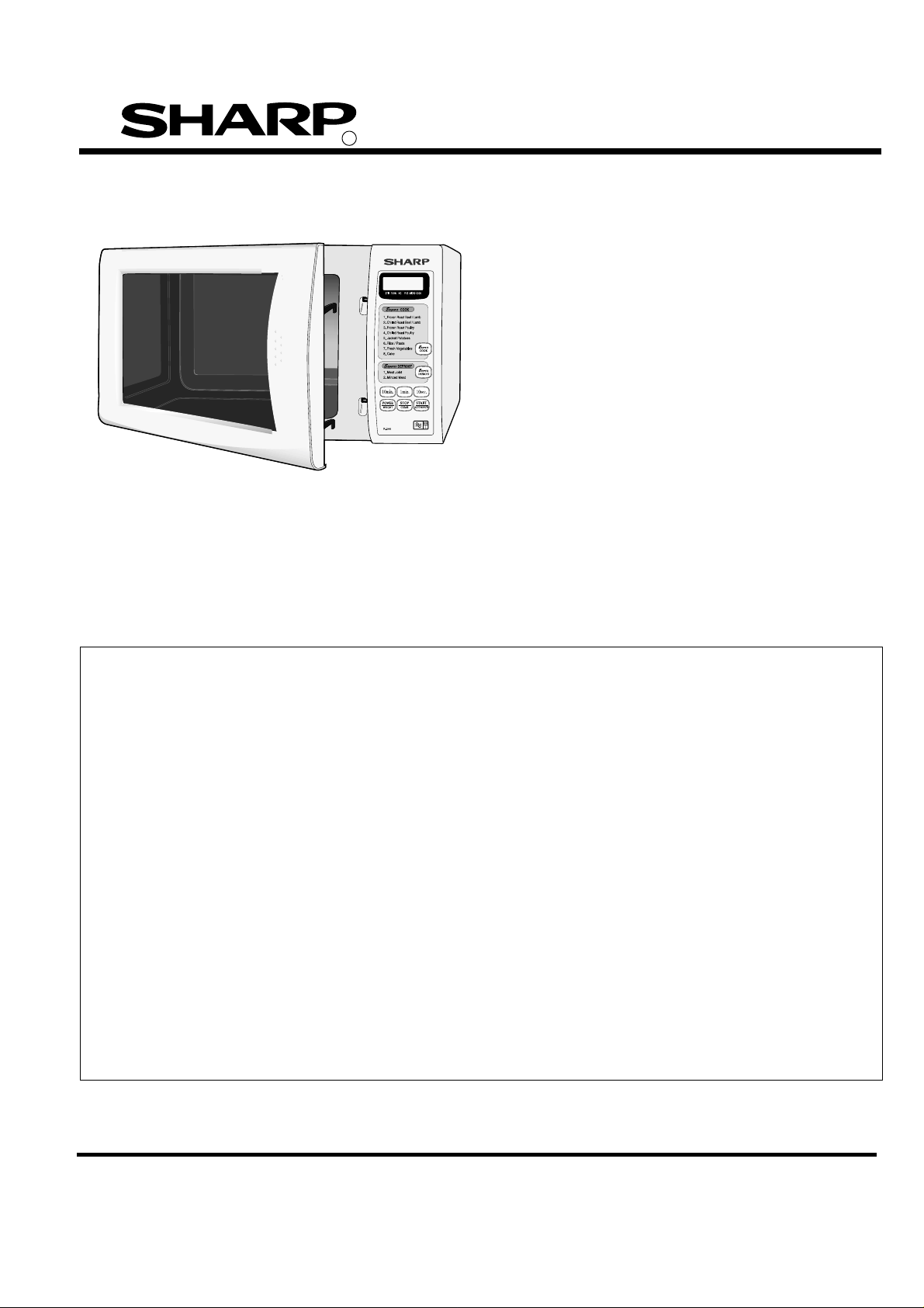
MICROWAVE OVEN
MODELS
R-244(W)M
R-244(G)M
R-244(B)M
R-244(SL)M
In interests of user-safety the oven should be restored to its
original condition and only parts identical to those specified
should be used.
TABLE OF CONTENTS
Page
SERVICING ............................................................................................................................................. 2
CAUTION/WARNING............................................................................................................................... 3
PRODUCT SPECIFICATIONS ................................................................................................................ 3
APPEARANCE VIEW................................................................................................................................ .4
OPERATION SEQUENCE........................................................................................................................ 5
OUTPUT POWER TEST PROCEDURE................................................................................................... 6
TEST PROCEDURES................................................................................................................................ 7
TOUCH CONTROL ASSEMBLY .............................................................................................................. 9
COMPONENT REPLACEMENT AND ADJUSTMENT PROCEDURE ................................................... 13
MICROWAVE MEASUREMENT PROCEDURE...................................................................................... 16
SCHEMATIC DIAGRAMS.........................................................................................................................17
PICTORIAL DIAGRAM .......................................................................................................................... 18
CONTROL PANEL CIRCUIT ................................................................................................................. 19
SWITCH UNIT CIRCUIT DIAGRAM ....................................................................................................... 20
PRINTED WIRING BOARD OF CONTROL PANEL DIAGRAM ............................................................. 21
PRINTED WIRING BOARD OF SWITCH UNIT DIAGRAM.................................................................... 22
PARTS LIST........................................................................................................................................... 23
EXPLODED DIAGRAM OF OVEN.......................................................................................................... 26
CONTROL PANEL/DOOR PARTS ......................................................................................................... 27
PACKING AND ACCESSORIES ........................................................................................................... 28
SHARP CORPORATION
R-244M -
1
SERVICING
WARNING TO SERVICE PERSONNEL
Microwave ovens contain circuitry capable of producing very high voltage and current. Contact with following parts
will result in electrocution:High voltage capacitor, High voltage transformer, Magnetron, High voltage rectifier, High voltage wires.
REMEMBER TO CHECK 3D
1) Disconnect the supply.
2) Door opened, and wedged open.
3) Discharge high voltage capacitor.
WARNING AGAINST THE CHARGE OF THE HIGH-VOLTAGE CAPACITOR
The high-voltage capacitor remains charged about 60 seconds after the oven has been switched off. Wait for 60
seconds and then short-circuit the connection of the high-voltage capacitor (that is, of the connecting lead from the
high-voltage rectifier) against the chassis using a screwdriver with an insulated handle.
Sharp recommend that wherever possible, fault-finding is carried out with the supply disconnected. In some cases,
it may be necessary to connect the supply with the cover removed to carry out fault investigation in the control
circuitry. In such cases, the high voltage circuit should be disabled as described below to reduce the hazards:-
• Carry out 3D checks (see above).
• Disconnect the supply leads from the high voltage transformer, making a note of the polarity. Insulate the
connectors, ensuring they are positioned away from the transformer and fastened there.
• Connect any relevant test equipment e.g. voltmeter.
• Reconnect the oven to the supply, then close the door.
• Note the results of the test, taking care to keep clear of the operational oven.
• Carry out 3D checks (see above).
• Reconnect the leads to the transformer. Take care to observe correct polarity.
• Carry out 4R checks (see below).
Microwave ovens should not be used without a load. To test for the presence of microwave energy within a cavity,
place a cup of cold water on the oven turntable, close the door and set the microwave timer for one (1) minute, set the
power level to HIGH (100%) and push the start key. When the one (1) minute has elapsed (timer at zero) carefully check
that the water is now hot.
AFTER REPAIR REMEMBER TO CHECK 4R
1) Reconnect all leads removed from components during testing.
2) Replace the outer case (cabinet).
3) Reconnect the supply.
4) Run the oven. Check all functions.
When all service work is completed, and the oven is fully assembled, the microwave power output should be checked
and microwave leakage test carried out.
IMPORTANT: If the oven becomes inoperative because of a blown F8A Fuse, check the monitored latch switch and
monitor switch before replacing the fuse .
WARNING: WIRING / RE-WIRING
Before carrying out any work; carry out 3D checks.
1) Disconnect the supply.
2) Open the door and wedge open.
3) Discharge the high voltage capacitor.
RE-WIRING
1) Wires must not touch:
a) High voltage parts.
b) Parts that become hot.
c) Sharp edges.
d) Movable parts.
2) Positive lock connectors are fitted correctly
3) Wires are connected correctly as per pictorial diagram.
4) No wire leads are trapped by the outer wrap.
R-244M -
2
CAUTION / WARNING
CAUTION
MICROWAVE RADIATION
Do not become exposed to radiation from the magnetron
or other parts conducting microwave energy. All input
and output microwave connections, waveguides, flanges
and gaskets must be secured. Never operate the
device without a microwave energy absorbing load
attached. Never look into an open waveguide or antenna while the device is energized.
Servicing and repair work must be carried out only by
trained service engineers.
The parts marked '*' on the parts list and schematic
diagram have voltages in excess of 250V.
Removal of the outer wrap gives access to potential
above 250V.
All the parts marked "∆" on the parts list may cause undue
microwave exposure, by themselves, or when they are
damaged, loosened or removed.
WARNING
WARNING
THIS APPLIANCE MUST BE EARTHED. THE WIRES IN THIS MAINS LEAD ARE COLOURED IN
ACCORDANCE WITH THE FOLLOWING CODE:
GREEN-AND-YELLOW : EARTH BLUE : NEUTRAL BROWN : LIVE
If the mains lead is replaced, only part number QACCBA030WRE4 should be used
PRODUCT DESCRIPTION
SPECIFICATION
Power Requirements 230-240 Volts 50 Hertz Single phase, 3 wire grounded
Power Consumption 1.2kW
Power Output 800W watts nominal of RF microwave energy (measured by way of IEC60705)
Operating frequency of 2450 MHz
Case Dimensions Width 449mm / Height 282mm including foot / Depth 385mm
Cooking Cavity Dimensions Width 287mm / Height 220mm / Depth 311mm
Turntable diameter 272mm
Control Complement Touch Control System
Clock(1:00-12:59 or 0:00-23:59)
Microwave Power for Variable Cooking
Repetition Rate;
HIGH .................. Full power throughout the cooking time
MEDIUM HIGH ...................... approx. 70% of Full Power
MEDIUM ................................ approx. 50% of Full Power
MEDIUM LOW....................... approx. 30% of Full Power
LOW ...................................... approx. 10% of Full Power
EXPRESS COOK button
EXPRESS DEFROST button
POWER LEVEL/WEIGHT button
STOP/CLEAR button
START/AUTO MINUTE button
Net Weight Approx. 13.3 kg
As part of our policy of continuous improvement, we reserve the right to
alter design and specifications without notice
R-244M -
3
APPEARANCE VIEW
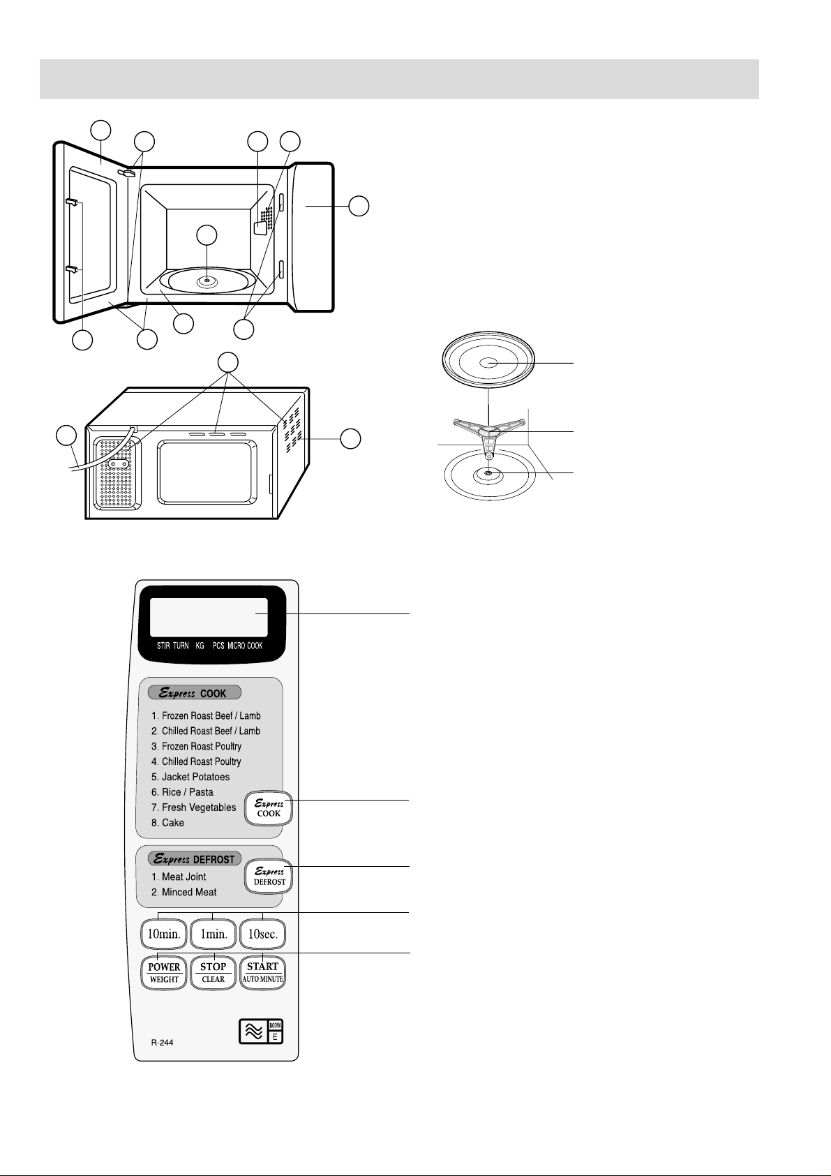
OVEN
13
10
1. Door
1
2
3 4
5
6
8
9
7
11
2. Door hinges
3. Waveguide cover
4. Oven lamp
5. Control panel
6. Rubber seal
7. Door latch openings
8. Oven cavity
9. Door seals and sealing surfaces
10. Safety door latches
11. Ventilation openings
12. Outer case
13. Power supply cord
Turntable
Roller stay
12
Seal packing
1. Place the roller stay on the floor of the oven cavity,
engaging shaft.
2. Then place the turntable on the roller stay.
1.
1. DIGITAL DISPLAY
2. EXPRESS COOK pad
2.
3. EXPRESS DEFROST pad
4. TIMER Pads
5. POWER /WEIGHT STOP/CLEAR
START/AUTO MINUTE Pads
3.
4.
R-244M -
5.
4
OPERATING SEQUENCE
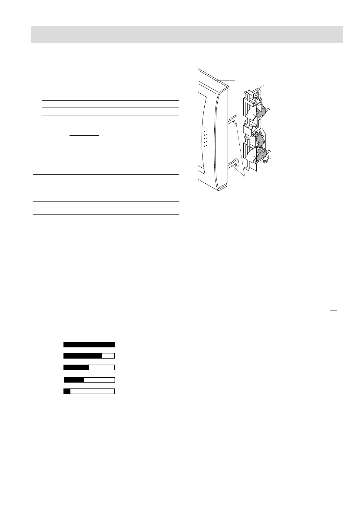
Latch hook
SW3: Stop switch
Door
SW2: Monitor switch
SW1: Monitored latch switch
Latch heads
OFF CONDITION
1. When the oven door is opened, the oven lamp comes on
at this time.
MICROWAVE COOKING CONDITION
CONNECTED COMPONENTS RELAY
Oven lamp, Fan motor, Turntable motor RY1
Power transformer RY2
2. When the cooking time is up, a single tone is heard and
the relays
RY1 + RY2 go back to their home position.
The circuits to the oven lamp, power transformer, fan
motor and turntable motor are cut off.
3. When the door is opened during a cook cycle, the
switches come to the following condition.
CONDITION
SWITCH CONTACT COOKING (NO COOKING)
Monitor switch COM-NC Open Closed
Monitored latch switch COM-NO Closed Open
Stop switch COM-NO Closed Open
DURING DOOR OPEN
The circuits to the power transformer, fan motor and
turntable motor are cut off when the monitored latch switch
and stop switch are made open.
The oven lamp remains on even if the oven door is opened
after the cooking cycle has been interrupted, because the
relay
RY1 stays closed. Shown in the display is the remaining
time.
HIGH, MEDIUM HIGH, MEDIUM, MEDIUM
LOW, LOW COOKING
When the microwave oven is preset for variable cooking
power, the line voltage is supplied to the power transformer
intermittently within a 32-second time base through the
relay contact which is coupled with the current-limiting relay
(RY2). The following levels of microwave power are given.
SETTING
32 sec. ON
HIGH
MEDIUM HIGH
MEDIUM
MEDIUM LOW
LOW
24 sec. ON
18 sec. ON
12 sec. ON
6 sec. ON
8 sec. OFF
14 sec. OFF
20 sec. OFF
26 sec. OFF
NOTE: The ON/OFF time ratio does not exactly correspond
to the percentage of microwave power, because
approx. 3 seconds are needed for heating up the
magnetron filament.
Approx. 100% = 800 Watts
Approx. 70% = 560Watts
Approx. 50% = 400 Watts
Approx. 30% = 240 Watts
Approx. 10% = 80 Watts
DOOR OPEN MECHANISM
The door can be opened by pulling the door.
Figure D-1. Door Open Mechanism
MONITORED LATCH SWITCH AND STOP
SWITCH
1. When the oven door is closed, the contacts (COM-NO)
must be closed.
MONITOR SWITCH
1. When the oven door is closed, the contacts (COM-NC)
must be opened.
2. When the oven door is opened, the contacts (COMNC) must be closed.
3. If the oven door is opened and he contacts (COM-NO)
of the monitored latch switch fail to open, the fuse F1
blows immediately after closing the contacts (COMNC) of the monitor switch.
CAUTION: BEFORE REPLACING A BLOWN FUSE
F1
TEST MONITORED LATCH SWITCH (SW1)
AND MONITOR SWITCH FOR PROPER
OPERATION. (REFER TO CHAPTER “TEST
PROCEDURE”).
FUSE
1. The fuse F1 blows when the contacts (COM-NO) of the
monitored latch switch remain closed with the oven
door open and when the contacts (COM-NC) of the
monitor switch are closed.
2. If the wire harness or electrical components are shortcircuited, the fuse F1 blows to prevent an electric shock
or fire hazard.
HVT THERMOSTAT 150˚C
The thermostat protects the high voltage transformer against
overheating. If the temperature goes up higher than 150˚C
because the fan motor is interrupted or the ventilation
openings are blocked, the thermostat will cycle, line voltage to the high voltage transformer will also cycle. (If
operated, check the magnetron for damage.)
R-244M -
5

OPERATING SEQUENCE
THERMAL CUT-OUT 125˚C (OVEN)
The thermal cut-out located on the top of the oven cavity is
designed to prevent damage to the oven, if the food in the
oven catch fire due to over heating produced by improper
setting of cook time or failure of control unit. Under normal
operation, the thermal cut-out remains closed. However,
when abnormally high temperatures are reached within the
oven cavity, the thermal cut-out will open at 125˚C, causing
the oven to shut down. The defective thermal cut-out must be
replaced with a new one.
TURNTABLE MOTOR
The turntable motor drives the turntable roller assembly to
rotate the turntable.
OUTPUT POWER TEST PROCEDURE
MICROWAVE OUTPUT POWER (IEC-60705)
FAN MOTOR
The fan motor drives a blade which draws external cool air.
This cool air is directed through the air vanes surrounding
the magnetron and cools the magnetron. This air is channelled through the oven cavity to remove steam and vapours
given off from heating food. It is then exhausted through the
exhaust vents at the rear of the oven cavity.
NOISE FILTER
The noise filter assembly prevents radio frequency interference that might flow back into the power circuit.
The power output of this oven is rated using the method specified by IEC-60705. Full details of how to carry out this
procedure can be found in the Sharp Technical Training notes which is available from Sharp Parts Centre
(part number SERV-LITMW01).
Using this procedure, the heating time to raise 1000g of water by 10°C is approximately 50 seconds.
The IEC-60705 procedure must be carried out using laboratory-type procedures and equipment. These requirements
make the procedure unsuitable for routing performance checks. An indication of the power being produced by the oven
can however be obtained using the procedure given below.
Alternative simplified method:
1. Place 2 litres of cold water (between 12°C and 20°C) in a suitable container.
2. Stir the water and measure the temperature in °C. Note temperature as T1.
3. Place the container in the microwave and heat the water for 2 minutes on full power.
4. When the 2 minutes is completed, remove the container and stir the water. Note the water temperature as T2.
5. Calculate the output power using the following formula:
R.F. Power Output = (T2 - T1) x 70.
Note: The result from this test should be within 10% of the power rating stated on the rating label.
MICROWAVE LEAKAGE TEST
This oven should be tested for microwave leakage on completion of any repair or adjustment, following the procedure
described in the Sharp Technical Training notes (part number SERV-LITMW01). The maximum leakage permitted in
BS EN 60335-2-25 is 50W/m
therefore, any leakage which is detected should be investigated.
2
(equivalent to 5mW/cm2), however it is not normal to detect any significant leakage,
It is essential that only leakage detectors with current calibration traceable to the National Physical Laboratories are used.
Suitable leakage detectors : CELTEC A100
APOLLO X1
R-244M -
6

TEST PROCEDURES
PROCEDURE
LETTER
A TOUCH CONTROL PANEL ASSEMBLY TEST
Do not touch the electrical parts and the printed wiring board to prevent an electric
CAUTION shock. Because the control unit is " TRANSLESS CIRCUIT " and all electrical parts
are used at A.C. line voltage.
The touch control panel consists of circuits including semiconductors such as LSI, ICs, etc. Therefore,
unlike conventional microwave ovens, proper maintenance cannot be performed with only a voltmeter
and ohmmeter.
In this service manual, the touch control panel assembly is divided into two units, Control Unit and
Switch Unit, and troubleshooting by unit replacement is described according to the symptoms
indicated.
1. Switch Unit. Note : Check switch unit lead wire harness connection before replacement.
The following symptoms indicate a defective switch unit. Replace the switch unit.
a) When touching the keys, a certain key produces no signal at all.
b) When touching a key, two figures or more are displayed.
c) When touching the keys, sometimes a key produces no signal.
2. Control Unit
The following symptoms indicate a defective control unit. Before replacing the control unit
perform the Switch unit test (Procedure M) to determine if control unit is faulty.
2-1 In connection with keys.
a) When touching the keys, a certain group of keys do not produce a signal.
b) When touching the keys, no keys produce a signal.
2-2 In connection with indicators
a) At a certain digit, all or some dots do not light up.
b) At a certain digit, brightness is low.
c) Only one indicator does not light.
d) The corresponding dots of all digits do not light up; or they continue to light up.
e) Wrong figure appears.
f) A certain group of indicators do not light up.
g) The figure of all digits flicker.
2-3 Other possible problems caused by defective control unit.
a) Buzzer does not sound or continues to sound.
b) Clock does not operate properly.
c) Cooking is not possible.
COMPONENT TEST
B TACT SWITCH TEST
1. Disconnect the oven from the power supply.
2. Discharge the high voltage capacitor.
3. Remove the control unit from the control panel.
4. By using an ohmmeter, check the tact switch operation.
5. When the tact switch is not depressed, an ohmmeter should indicate an open circuit. When the tact
switch is depressed, an ohmmeter should indicate a short circuit. If improper operation is indicated,
the tact switch is probably defective and should be checked.
C RELAY TEST
Remove the outer case and check voltage between Pin No 5 of the 3 pin connector (A) and common
terminal of the relay (RY2) on the control unit with an A.C. voltmeter.
The meter should indicate rated voltage, if not check oven circuit.
RY1 and RY2 Relay Test
These relays are operated by D.C. voltage
Check voltage at the relay coil with a D.C. voltmeter during the microwave cooking operation.
DC. voltage indicated.............Defective relay.
DC. voltage not indicated....... Check diode which is connected to the relay coil. If diode is good, control
RELAY SYMBOL OPERATIONAL VOLTAGE CONNECTED COMPONENTS
RY1 Approx. 18.0V D.C. Oven lamp / Turntable motor / Cooling fan motor
RY2 Approx. 7.0V D.C. High voltage transformer
unit is defective.
R-244M -
7
PROCEDURE
LETTER
D SWITCH UNIT TEST
TEST PROCEDURES
COMPONENT TEST
If the display fails to clear when the STOP/CLEAR
key is depressed, first verify the lead wire harness
is making good contact, verify that the stop switch
operates properly; that is the contacts are closed
when the door is closed and open when the door is
open. If the stop switch is good, disconnect the
lead wire harness that connects the switch unit to
the display unit and make sure the stop switch is
closed (either close the door or short the stop
switch connector). Use the Switch unit matrix indicated on the switch unit circuit and place a jumper
wire between the pins that correspond to the
STOP/CLEAR key making momentary contact. If
the display unit responds by clearing with a beep
the switch unit is faulty and must be replaced. If the
display unit does not respond, it is a faulty and must
be replaced. If a specific key does not respond, the
above method may be used (after clearing the
display unit) to determine if the display unit or
switch unit is at fault.
START
AUTO MINUTE
POWER
WEIGHT
STOP
CLEAR
min.
10
min.
1
DEFROST
sec.
10
COOK
SW1
SW2
SW3
SW4
SW5
SW6
SW7
SW8
CN - C
1
2
3
4
5
6
CN - C
6Pin HARNESS
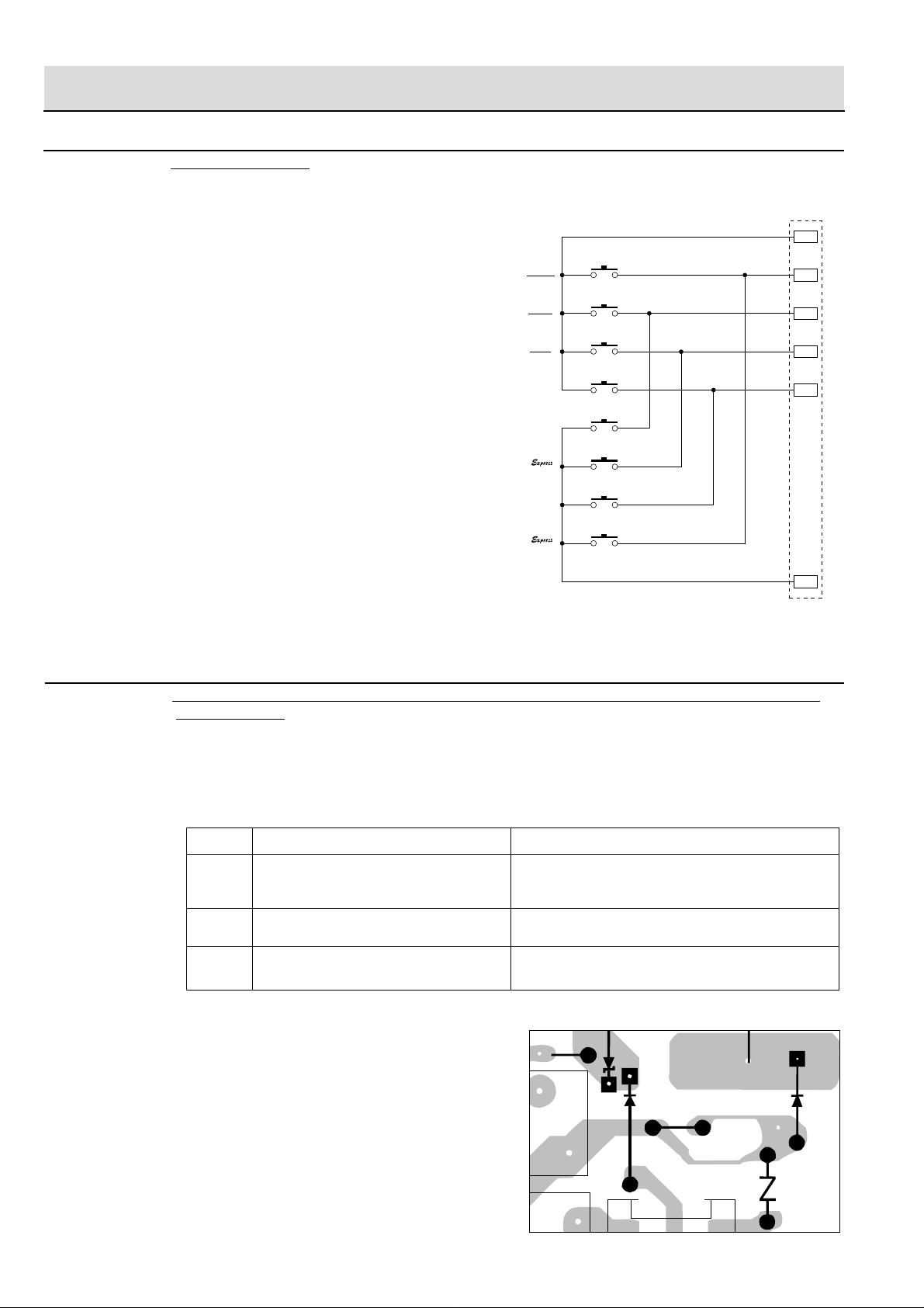
E PROCEDURES TO BE TAKEN WHEN THE FOIL PATTERN ON THE PRINTED WIRING BOARD
(PWB) IS OPEN
To protect the electronic circuits, this model is provided with a fine foil pattern added to the input circuit on
the PWB, this foil pattern acts as a fuse. If the foil pattern is open, follow the troubleshooting guide given
below for repair.
Problem: POWER ON, indicator does not light up.
STEPS OCCURRENCE CAUSE OR CORRECTION
1 The rated voltage is not applied between Pin Check supply voltage and oven power cord.
No. 5 of the 3 pin connector (A) and the
common terminal of the relay RY2.
2 Only pattern at "a" is broken. *Insert jumper wire J1 and solder.
3 Pattern at "a" and "b" are broken. *Insert the coil RCILF2003YAZZ between "c" and "d".
NOTE: *At the time of making these repairs,
ZD70
R70
R1
make a visual inspection of the varistor.
Check for burned damage. If any abnormal condition is detected, replace
the defective parts.
D71
c
(J1)
a
b
d
VRS1
RY2
RY1
R-244M -
51
8

TOUCH CONTROL PANEL ASSEMBLY
OUTLINE OF TOUCH CONTROL PANEL
The touch control section consists of the following units.
(1) Switch Unit
(2) Control Unit
The principal functions of these units and the signals
communicated among them are explained below.
4) Relay Circuit
To drive the magnetron, fan motor, turntable motor and
light the oven lamp.
5) Buzzer Circuit
The buzzer is responsive to signals from the LSI to emit
audible sounds (tact switch touch sound and completion
sound).
Switch Unit
The switch unit is composed of a matrix, signals generated
in the LSI are sent to the switch unit through R60, R61, R62
and R63.
When a switch button is touched, a signal is completed
through the switch unit and passed back to the LSI through
R81 and R83 to perform the function that was requested.
Control Unit
Control unit consists of LSI, ACL circuit, indicator circuit,
power source circuit, relay circuit, buzzer circuit, synchronizing signal circuit and back light circuit.
1) ACL
This circuit generates a signal which resets the LSI to the
initial state when power is supplied.
2) Indicator Circuit
This circuit consists of 4-digits, 12-segments and 3common electrodes using a Liquid Crystal Display.
3) Power Source Circuit
This circuit generates voltage necessary in the control unit
from the AC line voltage.
6) Synchronizing Signal Circuit
The power source synchronizing signal is available in
order to compose a basic standard time in the clock circuit.
It accompanies a very small error because it works on
commercial frequency.
7) Door Sensing Switch (Stop Switch)
A switch to "tell" the LSI if the door is open or closed.
8) Back Light Circuit
A circuit to drive the back light (Light emitting diodes
LED1-LED3)
Symbol Voltage Application
VC +5V LSI(IC1)
R-244M -
9
 Loading...