

Page 1
SERVICE MANUAL
CODE: 00ZMXM450/S1E
LASER PRINTER
MX-M350/M450 U
MODEL
CONTENTS
[1] GENERAL. . . . . . . . . . . . . . . . . . . . . . . . . . . . . . . . . . . . . . . . . . . . 1-1
[2] CONFIGURATION . . . . . . . . . . . . . . . . . . . . . . . . . . . . . . . . . . . . . 2-1
[3] SPECIFICATIONS . . . . . . . . . . . . . . . . . . . . . . . . . . . . . . . . . . . . . 3-1
[4] CONSUMABLE PARTS . . . . . . . . . . . . . . . . . . . . . . . . . . . . . . . . . 4-1
[5] EXTERNAL VIEWS AND INTERNAL STRUCTURES . . . . . . . . . . 5-1
[6] UNPACKING AND INSTALLATION. . . . . . . . . . . . . . . . . . . . . . . . . 6-1
[7] MAINTENANCE AND DETAILS OF EACH SECTION . . . . . . . . . . 7-1
[8] ADJUSTMENTS . . . . . . . . . . . . . . . . . . . . . . . . . . . . . . . . . . . . . . . 8-1
[9] SIMULATIONS . . . . . . . . . . . . . . . . . . . . . . . . . . . . . . . . . . . . . . . . 9-1
MX-M350/M450 N
[10] MACHINE OPERATION . . . . . . . . . . . . . . . . . . . . . . . . . . . . . . . . 10-1
[11] TROUBLE CODES. . . . . . . . . . . . . . . . . . . . . . . . . . . . . . . . . . . . 11-1
[12] ROM VERSION-UP METHOD . . . . . . . . . . . . . . . . . . . . . . . . . . . 12-1
[13] ELECTRICAL SECTION. . . . . . . . . . . . . . . . . . . . . . . . . . . . . . . . 13-1
Parts marked with “ ” are important for maintaining the safety of the set. Be sure to replace these parts with
specified ones for maintaining the safety and performance of the set.
This document has been published to be used
SHARP CORPORATION
for after sales service only.
The contents are subject to change without notice.
Page 2
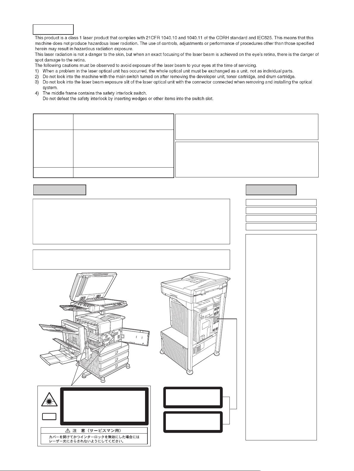
CAUTION
Cautions on laser
Wave length
Pulse times
Output power
North America:
Europe:
785 nm
+10 nm
−15 nm
35 cpm model: (6.2 µs ± 6.2 ns)/7 mm
45 cpm model: (4.8 µs ± 4.8 ns)/7 mm
35 cpm model: (6.2 µs ± 6.2 ns)/7 mm
45 cpm model: (4.8 µs ± 4.8 ns)/7 mm
0.2 mW - 0.4 mW
At the production line, the output power of the scanner unit
is adjusted to 0.4 MILLIWATT PLUS 8 % and is maintained
constant by the operation of the Automatic Power Control (APC).
Caution
This product contains a low power laser device. To ensure
safety do not remove any cover or attempt to gain access
to the inside of the product. Refer all servicing to qualified
personnel.
For North America:
SAFETY PRECAUTIONS
This Digital Equipment is rated Class 1 and complies with 21 CFR 1040.10 and 1040.11 of the
CDRH standards. This means that the equipment does not produce hazardous laser radiation. For
your safety, observe the precautions below.
●
Do not remove the cabinet, operation panel or any other covers.
●
The equipment's exterior covers contain several safety interlock switches. Do not bypass any
safety interlock by inserting wedges or other items into switch slots.
Caution
Use of controls or adjustments or performance of procedures other than those specified herein may result in
hazardous radiation exposure.
INVISIBLE LASER RADIATION WHEN OPEN AND INTERLOCKS DEFEATED.
AVOID EXPOSURE TO BEAM.
Laserstrahl
CAUTION
UNSICHTBARE LASERSTRAHLUNG WENN ABDECKUNG GEÖFFNET UND
SICHERHEITSVERRIEGELUNG ÜBERERÜCKT. NICHT DEM STRAHL AUSSETZEN.
VORSICHT
USYNLIG LASERSTRÅLING VED ÅBNING, NÅR SIKKERHEDSAFBRYDERE ER
UDE AF FUNKTION. UNDGÅ UDSAETTELSE FOR STRÅLNING.
ADVARSEL
USYNLIG LASERSTRÅLING NÅR DEKSEL ÅPNES OG SIKKERHEDSLÅS BRYTES.
UNNGÅ EKSPONERING FOR STRÅLEN.
ADVERSEL
OSYNLIG LASERSTRÅLNING NÄR DENNA DEL ÄR ÖPPNAD OCH SPÄRRAR ÄR
URKOPPLADE. STRÅLEN ÄR FARLIG. BETRAKTA EJ STRÅLEN.
VARNING
AVATTAESSA JA SUOJALUKITUS OHITETTAESSA OLET ALTTIINA NÄKYMÄTÖNTÄ
LASERSÄTEILYLLE. ÄLÄ KATSO SÄTEESEEN.
VARO !
CLASS 1
LASER PRODUCT
LASER KLASSE 1
For Europe:
CLASS 1 LASER PRODUCT
LASER KLASSE 1
LUOKAN 1 LASERLAITE
KLASS 1 LASERAPPARAT
CAUTION
INVISIBLE LASER RADIATION
WHEN OPEN INTERLOCKS
DEFEATED. AVOID EXPOSURE
TO BEAM.
VORSICHT
UNSICHTBARE
LASERSTRAHLUNG WENN
ABDECKUNG GEÖFFNET UND
SICHERHEITSVERRIEGELUNG
ÜBERBRÜCKT. NICHT DEM
STRAHL AUSSETZEN.
ADVARSEL
USYNLIG LASERSTRÅLNING
VED ÅBNING, NÅR
SIKKERHEDSBRYDERE ER
UDE AF FUNKTION. UNDGÅ
UDSAETTELSE FOR
STRÅLNING.
VAROITUS!
LAITTEEN KÄYTTÄMINEN
MUULLA KUIN TÄSSÄ
KÄYTTÖOHJEESSA
MAINITULLA TAVALLA SAATTAA
ALTISTAA KÄYTTÄJÄN
TURVALLISUUSLUOKAN 1
YLITTÄVÄLLE
NÄKYMÄTTÖMÄLLE
LASERSÄTEILYLLE.
VARNING
OM APPARATEN ANVÄNDS PÅ
ANNAT SÄTT ÄN I DENNA
BRUKSANVISNING
SPECIFICERATS, KAN
ANVÄNDAREN UTSÄTTAS FÖR
OSYNLIG LASERSTRÅLNING,
SOM ÖVERSKRIDER GRÄNSEN
FÖR LASERKLASS 1.
Page 3

CONTENTS
[1] GENERAL
1. Different points of MX-M350N/350U series
from AR-M355/M455 . . . . . . . . . . . . . . . . . . . . . . . . .1-1
2. Note for servicing . . . . . . . . . . . . . . . . . . . . . . . . . . . .1-1
A. Cautions for servicing . . . . . . . . . . . . . . . . . . . . . .1-1
[2] CONFIGURATION
1. System configuration . . . . . . . . . . . . . . . . . . . . . . . . .2-1
A. Basic system . . . . . . . . . . . . . . . . . . . . . . . . . . . . .2-1
B. Option lineup . . . . . . . . . . . . . . . . . . . . . . . . . . . . .2-2
C. List of combination of peripheral devices . . . . . . .2-4
[3] SPECIFICATIONS
1. Basic Specification . . . . . . . . . . . . . . . . . . . . . . . . . . .3-1
A. Base Engine . . . . . . . . . . . . . . . . . . . . . . . . . . . . .3-1
B. Document Feeding Equipment . . . . . . . . . . . . . . .3-2
C. Output Equipment . . . . . . . . . . . . . . . . . . . . . . . . .3-2
2. Specific Function . . . . . . . . . . . . . . . . . . . . . . . . . . . .3-2
A. Printer Function . . . . . . . . . . . . . . . . . . . . . . . . . . .3-2
B. Image send function . . . . . . . . . . . . . . . . . . . . . . .3-5
C. Copy function . . . . . . . . . . . . . . . . . . . . . . . . . . . .3-7
3. B/W Scanner Module (DSPF) . . . . . . . . . . . . . . . . . . .3-8
4. Rack for Scanner . . . . . . . . . . . . . . . . . . . . . . . . . . . .3-9
[4] CONSUMABLE PARTS
1. Supply system table . . . . . . . . . . . . . . . . . . . . . . . . . .4-1
A. USA/Canada . . . . . . . . . . . . . . . . . . . . . . . . . . . . .4-1
B. European Subsidiary/East Europe/Russia/
Australia/New Zealand . . . . . . . . . . . . . . . . . . . . .4-1
C. Taiwan (Aurora). . . . . . . . . . . . . . . . . . . . . . . . . . .4-1
D. Asia . . . . . . . . . . . . . . . . . . . . . . . . . . . . . . . . . . . .4-1
E. Middle East/Africa/Israel/Philippines . . . . . . . . . . .4-1
F. Hong Kong . . . . . . . . . . . . . . . . . . . . . . . . . . . . . .4-1
G. China . . . . . . . . . . . . . . . . . . . . . . . . . . . . . . . . . . .4-1
2. Maintenance parts list. . . . . . . . . . . . . . . . . . . . . . . . .4-2
A. USA/Canada . . . . . . . . . . . . . . . . . . . . . . . . . . . . .4-2
B. Europe/Australia/New Zealand/Taiwan. . . . . . . . .4-2
C. Agency/Asia/Middle East/Africa/
Latin America . . . . . . . . . . . . . . . . . . . . . . . . . . . .4-3
D. Hong Kong . . . . . . . . . . . . . . . . . . . . . . . . . . . . . .4-3
E. China . . . . . . . . . . . . . . . . . . . . . . . . . . . . . . . . . . .4-4
2. Production number identification . . . . . . . . . . . . . . . .4-5
A. Drum cartridge. . . . . . . . . . . . . . . . . . . . . . . . . . . .4-5
B. Toner cartridge . . . . . . . . . . . . . . . . . . . . . . . . . . .4-5
C. Developer cartridge . . . . . . . . . . . . . . . . . . . . . . . .4-5
3. Environmental conditions . . . . . . . . . . . . . . . . . . . . . .4-5
A. Operating conditions . . . . . . . . . . . . . . . . . . . . . . .4-5
B. Storage conditions. . . . . . . . . . . . . . . . . . . . . . . . .4-5
[5] EXTERNAL VIEWS AND INTERNAL STRUCTURES
1. Exterior . . . . . . . . . . . . . . . . . . . . . . . . . . . . . . . . . . . 5-1
2. Interior . . . . . . . . . . . . . . . . . . . . . . . . . . . . . . . . . . . . 5-2
3. Operation panel. . . . . . . . . . . . . . . . . . . . . . . . . . . . . 5-3
4. Job status screen
(common to print, scan, fax and Internet fax) . . . . . . 5-4
5. BASE SCREEN. . . . . . . . . . . . . . . . . . . . . . . . . . . . . 5-5
A. Condition settings screen. . . . . . . . . . . . . . . . . . . 5-5
B. Address book screen . . . . . . . . . . . . . . . . . . . . . . 5-6
6. Cross sectional view . . . . . . . . . . . . . . . . . . . . . . . . . 5-7
A. Scanner unit . . . . . . . . . . . . . . . . . . . . . . . . . . . . . 5-7
B. Engine . . . . . . . . . . . . . . . . . . . . . . . . . . . . . . . . . 5-7
7. Switch, Sensor . . . . . . . . . . . . . . . . . . . . . . . . . . . . . 5-8
A. Scanner unit . . . . . . . . . . . . . . . . . . . . . . . . . . . . . 5-8
B. Engine . . . . . . . . . . . . . . . . . . . . . . . . . . . . . . . . . 5-8
8. PWB . . . . . . . . . . . . . . . . . . . . . . . . . . . . . . . . . . . . . 5-9
A. Scanner unit . . . . . . . . . . . . . . . . . . . . . . . . . . . . . 5-9
B. Engine . . . . . . . . . . . . . . . . . . . . . . . . . . . . . . . . . 5-9
9. Motor, Clutch, Solenoid . . . . . . . . . . . . . . . . . . . . . . 5-10
A. Scanner unit . . . . . . . . . . . . . . . . . . . . . . . . . . . . 5-10
B. Engine . . . . . . . . . . . . . . . . . . . . . . . . . . . . . . . . 5-10
[6] UNPACKING AND INSTALLATION
1. Installing procedure flowchart . . . . . . . . . . . . . . . . . . 6-1
2. Note for installation place . . . . . . . . . . . . . . . . . . . . . 6-2
3. Unpacking procedure . . . . . . . . . . . . . . . . . . . . . . . . 6-2
4. Unpacking and installation of the desk unit . . . . . . . . 6-3
A. AR-D28 . . . . . . . . . . . . . . . . . . . . . . . . . . . . . . . . 6-3
B. AR-D27 . . . . . . . . . . . . . . . . . . . . . . . . . . . . . . . . 6-5
C. AR-MU2 . . . . . . . . . . . . . . . . . . . . . . . . . . . . . . . . 6-6
5. Unpacking and installation of the rack (AR-RK2) . . . 6-9
6. Machine installing procedure. . . . . . . . . . . . . . . . . . . 6-9
A. Setting related to process . . . . . . . . . . . . . . . . . . 6-9
B. Toner cartridge settings . . . . . . . . . . . . . . . . . . . 6-10
C. Setting related to fusing . . . . . . . . . . . . . . . . . . . 6-10
D. Paper setting . . . . . . . . . . . . . . . . . . . . . . . . . . . 6-10
7. Unpacking and installation of the MX-EFX1 . . . . . . 6-11
8. Automatic developer adjustment . . . . . . . . . . . . . . . 6-12
9. Print test . . . . . . . . . . . . . . . . . . . . . . . . . . . . . . . . . 6-12
10. Distortion adjustment. . . . . . . . . . . . . . . . . . . . . . . . 6-12
11. Attach the document scanning label . . . . . . . . . . . . 6-13
12. Adjuster installation and adjustment . . . . . . . . . . . . 6-13
13. Using the transport handle . . . . . . . . . . . . . . . . . . . 6-13
Page 4

[7] MAINTENANCE AND DETAILS OF EACH SECTION
[Maintenance System Table] . . . . . . . . . . . . . . . . . . . . . . .7-1
1. Engine section . . . . . . . . . . . . . . . . . . . . . . . . . . . . . .7-1
2. Scanner / DSPF . . . . . . . . . . . . . . . . . . . . . . . . . . . . .7-2
3. Peripheral devices . . . . . . . . . . . . . . . . . . . . . . . . . . .7-3
[DETAILS OF EACH SECTION] . . . . . . . . . . . . . . . . . . . .7-4
1. Process section . . . . . . . . . . . . . . . . . . . . . . . . . . . . .7-4
[OPC drum section] . . . . . . . . . . . . . . . . . . . . . . . . . .7-6
[Transfer section] . . . . . . . . . . . . . . . . . . . . . . . . . . .7-11
[Developing section] . . . . . . . . . . . . . . . . . . . . . . . . .7-16
2. Fusing section. . . . . . . . . . . . . . . . . . . . . . . . . . . . . .7-21
3. Paper feed section . . . . . . . . . . . . . . . . . . . . . . . . . .7-26
4. Transport section/Paper exit reverse section . . . . . .7-33
5. Laser scanner section. . . . . . . . . . . . . . . . . . . . . . . .7-43
6. Scanner section . . . . . . . . . . . . . . . . . . . . . . . . . . . .7-46
7. DSPF section . . . . . . . . . . . . . . . . . . . . . . . . . . . . . .7-54
8. Operation panel section . . . . . . . . . . . . . . . . . . . . . .7-62
9. Filter . . . . . . . . . . . . . . . . . . . . . . . . . . . . . . . . . . . . .7-67
10. Drive section. . . . . . . . . . . . . . . . . . . . . . . . . . . . . . .7-68
11. Power section. . . . . . . . . . . . . . . . . . . . . . . . . . . . . .7-70
12. PWB . . . . . . . . . . . . . . . . . . . . . . . . . . . . . . . . . . . . .7-73
13. Fan motor . . . . . . . . . . . . . . . . . . . . . . . . . . . . . . . . .7-75
[8] ADJUSTMENTS
1. Process section . . . . . . . . . . . . . . . . . . . . . . . . . . . . .8-1
A. Doctor gap adjustment . . . . . . . . . . . . . . . . . . . . .8-1
B. MG roller main pole position adjustment . . . . . . . .8-1
C. High voltage output adjustment. . . . . . . . . . . . . . .8-2
2. Image check, adjustment . . . . . . . . . . . . . . . . . . . . . .8-3
A. Adjustments on the engine side . . . . . . . . . . . . . .8-3
B. Adjustment on the scanner side . . . . . . . . . . . . . .8-6
3. Scanner section . . . . . . . . . . . . . . . . . . . . . . . . . . . .8-10
A. OC scan distortion adjustment
(MB-B rail height adjustment) . . . . . . . . . . . . . . .8-10
B. Vertical image distortion balance adjustment
(Copy lamp unit installing position
adjustment) . . . . . . . . . . . . . . . . . . . . . . . . . . . . .8-11
C. Vertical image distortion balance adjustment
(No. 2/3 mirror base unit installing and
position adjustment) . . . . . . . . . . . . . . . . . . . . . .8-11
D. Vertical (sub scanning direction) distortion
adjustment [Winding pulley position
adjustment] . . . . . . . . . . . . . . . . . . . . . . . . . . . . .8-11
E. Height adjustment of original detection
light emitting unit . . . . . . . . . . . . . . . . . . . . . . . . .8-12
F. Original size detection photo sensor check. . . . .8-12
G. Original size detection photo sensor
adjustment. . . . . . . . . . . . . . . . . . . . . . . . . . . . . .8-12
H. Image density adjustment . . . . . . . . . . . . . . . . . .8-13
I. DSPF width detection adjustment. . . . . . . . . . . .8-17
[9] SIMULATION
1. Outline and purpose . . . . . . . . . . . . . . . . . . . . . . . . . 9-1
2. Code-type simulation. . . . . . . . . . . . . . . . . . . . . . . . . 9-1
A. Operating procedures and operations . . . . . . . . . 9-1
B. Simulation list. . . . . . . . . . . . . . . . . . . . . . . . . . . . 9-3
C. Details . . . . . . . . . . . . . . . . . . . . . . . . . . . . . . . . . 9-7
3. Other related items . . . . . . . . . . . . . . . . . . . . . . . . . 9-86
[10] MACHINE OPERATION
1. Acceptable originals . . . . . . . . . . . . . . . . . . . . . . . . 10-1
A. Size and weight of acceptable originals. . . . . . . 10-1
B. Total number of originals that can be set in the
document feeder tray . . . . . . . . . . . . . . . . . . . . . 10-1
2. Standard original placement orientations . . . . . . . . 10-1
3. Automatic copy image rotation -
rotation copying. . . . . . . . . . . . . . . . . . . . . . . . . . . . 10-1
4. Specifications of paper trays . . . . . . . . . . . . . . . . . . 10-2
A. Applicable plain paper . . . . . . . . . . . . . . . . . . . . 10-2
B. Applicable special paper . . . . . . . . . . . . . . . . . . 10-3
5. Printing onto envelopes. . . . . . . . . . . . . . . . . . . . . . 10-3
A. Fusing unit pressure adjusting levers . . . . . . . . 10-3
6. Printer setting . . . . . . . . . . . . . . . . . . . . . . . . . . . . . 10-4
A. System settings . . . . . . . . . . . . . . . . . . . . . . . . . 10-4
B. Printer software, firmware diagram . . . . . . . . . . 10-5
C. Configuration report (Test page) . . . . . . . . . . . . 10-6
[11] TROUBLE CODES
1. General . . . . . . . . . . . . . . . . . . . . . . . . . . . . . . . . . . 11-1
2. Trouble codes list . . . . . . . . . . . . . . . . . . . . . . . . . . 11-1
3. Details of trouble codes. . . . . . . . . . . . . . . . . . . . . . 11-3
4. Other related items . . . . . . . . . . . . . . . . . . . . . . . . 11-13
[12] ROM VERSION-UP
1. General . . . . . . . . . . . . . . . . . . . . . . . . . . . . . . . . . . 12-1
A. Version-up target ROM's . . . . . . . . . . . . . . . . . . 12-1
B. ROM version-up is required in the
following cases: . . . . . . . . . . . . . . . . . . . . . . . . . 12-1
2. Precautions . . . . . . . . . . . . . . . . . . . . . . . . . . . . . . . 12-1
A. Relationship between each ROM and
version-up . . . . . . . . . . . . . . . . . . . . . . . . . . . . . 12-1
3. Necessary items for Flash ROM version-up . . . . . . 12-1
4. Flash ROM version-up method . . . . . . . . . . . . . . . . 12-1
A. Version-up procedure 1 . . . . . . . . . . . . . . . . . . . 12-1
B. Version-up procedure 2 . . . . . . . . . . . . . . . . . . . 12-2
C. Version-up procedure 3 . . . . . . . . . . . . . . . . . . . 12-3
D. Countermeasures against “Result: NG” . . . . . . . 12-4
5. Turning OFF the power during the version-up
procedure . . . . . . . . . . . . . . . . . . . . . . . . . . . . . . . . 12-4
6. Version-up procedure flowchart . . . . . . . . . . . . . . . 12-4
[13] ELECTRICAL SECTION
1. Block diagram . . . . . . . . . . . . . . . . . . . . . . . . . . . . . 13-1
A. System block diagram . . . . . . . . . . . . . . . . . . . . 13-1
2. Actual wiring chart. . . . . . . . . . . . . . . . . . . . . . . . . . 13-2
3. Signal name list . . . . . . . . . . . . . . . . . . . . . . . . . . . 13-13
Page 5
[1] GENERAL
1. Different points of MX-M350N/350U series from AR-M355/M455
• Adopted new operation panel with 8.9 inch LCD
• Addition of a blue screw to DV unit.
• Added firmware version-up using USB device by Sim 49-1.
• Eliminated parallel port
2. Note for servicing
Pictogram
This Service Manual uses some pictographs to assure safe operation.
Please understand the meanings of pictographs before servicing.
CAUTION: If this CAUTION should be ignored, an injury or a
damage to properties could result.
A. Cautions for servicing
1) Do not touch the photoconductive drum. Scratches or
smudges on the drum will cause dirty printouts.
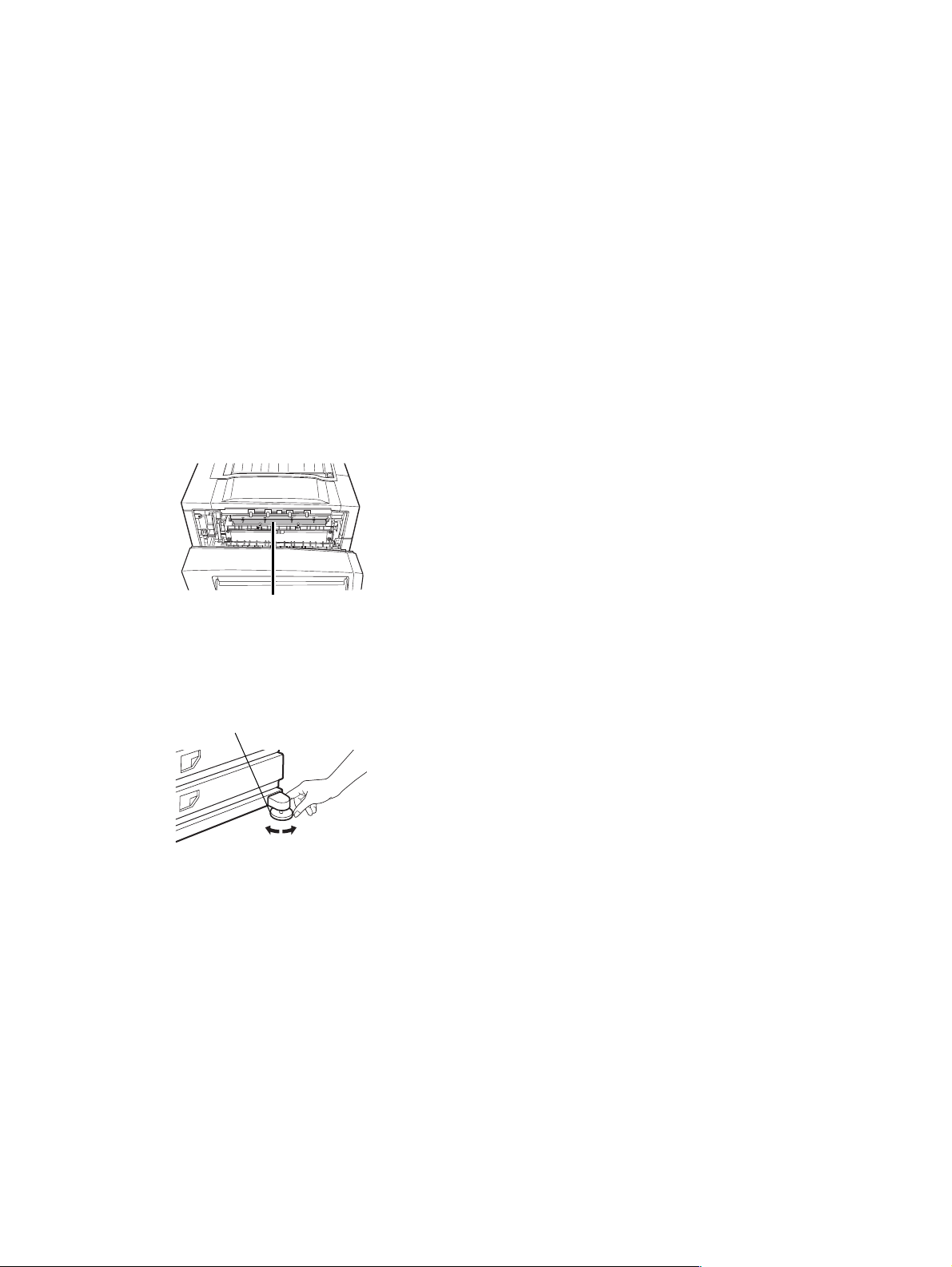
2) The fusing unit is extremely hot. Exercise care in this area.
8) Do not print anything which is prohibited from printing by law.
The following items are normally prohibited from printing by
national law. Other items may be prohibited by local law.
• Money
•Stamps
• Bonds
•Stocks
• Bank drafts
• Checks
• Passports
• Driver's licenses
9) Do not throw toner or a toner cartridge into fire. Toner may be
spattered, causing a burn.
10) Store toner or toner cartridges in a hard-to-reach place for
children.
Fusing unit
3) Do not look directly at the light source of the scanner module.
Doing so may damage your eyes.
4) Five adjusters are provided on all optional stand/paper drawer
units. These adjusters should be lowered until they contact the
floor.
Adjuster
Lock
5) Do not make any modifications to this machine. Doing so may
result in personal injury or damage to the machine.
6) Since this machine is heavy, it is recommended that it be
moved by more than one person to prevent injury.
7) When connecting this machine to a computer, be sure to first
turn both the computer and the machine off.
Release
MX-M350/M450 N/U GENERAL 1 - 1
Page 6
[2] CONFIGURATION
1. System configuration
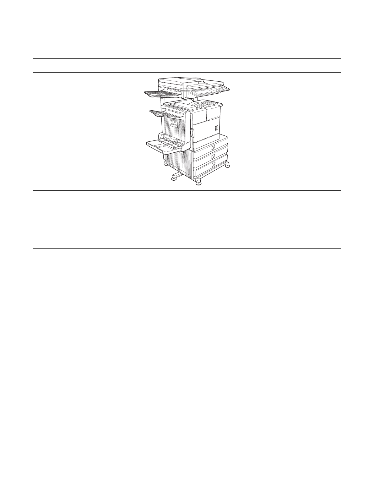
A. Basic system
MX-M350N/M450N
(Copier/Network printer model)
Necessary options
• Any one of the stand/MPD & 2000 sheet paper drawer (AR-D28), the stand/3 x 500 sheet paper drawer (AR-D27), or the multi purpose
drawer (AR-MU2)*
• Any one of the upper exit tray extension (AR-TE4), the finisher (AR-FN6), the mail-bin stacker (AR-MS1), the saddle stitch finisher (ARFN7), or the right upper exit tray (AR-TE5)
• Scanner module with DSPF (MX-EFX1)
• Scanner rack (AR-RK2)
• MX-M450U/M450N: Any one of the duplex module/bypass tray (AR-DU4), or the duplex module (AR-DU3)
* To install the AR-MU2, the exclusive-use desk is required.
MX-M350U/M450U
(Copier/Printer model)
MX-M350/M450 N/U CONFIGURATION 2 - 1
Page 7
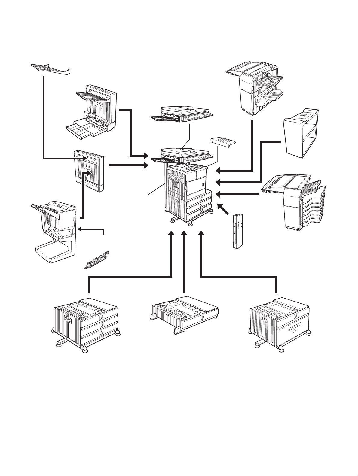
B. Option lineup
For combinations of options, refer to "C. List of combination of peripheral devices" described later.
(1) Major options
10. Exit tray
(AR-TE3 (The AR-DU4 is a standard provision. ))
11. Duplex
module/bypass tray
(AR-DU4)
12. Duplex module
(AR-DU3)
13. Saddle stitch
finisher
(AR-FN7)
2. Scanner rack
(AR-RK2)
1. Scanner module with DSPF
(MX-EFX1)
6. Upper exit tray
(AR-TE4)
7. Finisher
(AR-FN6)
8. Right upper exit
tray (AR-TE5)
9. Mail-bin stacker
(AR-MS1)
15. Fax expansion kit
(AR-FX12)
14. Punch module
(AR-PN1 A/B/C/D)
4. Stand/3 x 500 sheet
paper drawer
(AR-D27)
5. Multi purpose drawer
(AR-MU2)
3. Stand/MPD & 2000 sheet
paper drawer
(AR-D28)
MX-M350/M450 N/U CONFIGURATION 2 - 2
Page 8
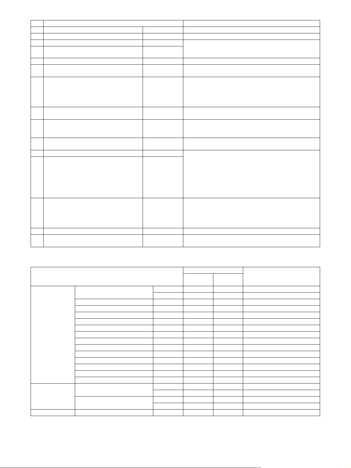
No. Option item Installing conditions
1 Scanner module with DSPF MX-EFX1
2 Scanner rack AR-RK2
3 Stand/MPD & 2000 sheet paper drawer AR-D28 • Simultaneous installation with the large capacity paper feed
4 Stand/3 x 500 sheet paper drawer AR-D27
desk (AR-D28) or the 3-stage paper feed desk (AR-D27) is
inhibited.
5 Multi purpose drawer AR-MU2
6 Upper exit tray AR-TE4 • Required when the finisher (AR-FN6) or the mail-bin stacker
(AR-MS1) is not installed.
7 Finisher AR-FN6 • Simultaneous installation with the saddle finisher (AR-FN7) is
inhibited.
• Any one of the multi paper drawer (AR-MU2), the stand/3 x
500 sheet paper drawer (AR-D27), or the stand/MPD & 2000
sheet paper drawer (AR-D28) is required.
8 Right upper exit tray AR-TE5 • Simultaneous installation with the mail-bin stacker (AR-MS1)
or the finisher (AR-FN6) is inhibited.
9 Mail-bin stacker AR-MS1 • Any one of the multi paper drawer (AR-MU2), the stand/3 x
500 sheet paper drawer (AR-D27), or the stand/MPD & 2000
sheet paper drawer (AR-D28) is required.
10 Exit tray AR-TE3 • Required when the duplex module (AR-DU3) is installed and
the saddle stitch finisher (AR-FN7) is not installed.
11 Duplex module/bypass tray AR-DU4 • Any one of the multi purpose drawer (AR-MU2), the stand/3 x
12 Duplex module AR-DU3
500 sheet paper drawer (AR-D27), or the stand/MPD & 2000
sheet paper drawer (AR-D28) is required.
• The duplex module/bypass tray (AR-DU4) cannot be installed
with the exit tray (AR-TE3) or the saddle stitch finisher (ARFN7).
• When the duplex module (AR-DU3) is installed, the exit tray
(AR-TE3) or the saddle stitch finisher (AR-FN7) is required.
13 Saddle stitch finisher AR-FN7 • Simultaneous installation with the finisher (AR-FN6) is
inhibited.
• The duplex module (AR-DU3) is required.
• The stand/3 x 500 sheet paper drawer (AR-D27) or the stand/
MPD & 2000 sheet paper drawer (AR-D28) is required.
14 Punch module AR-PN1 A/B/C/D • The saddle finisher (AR-FN7) is required.
15 Fax expansion kit AR-FX12 • The stand/3 x 500 sheet paper drawer (AR-D27), or the
stand/MPD & 2000 sheet paper drawer (AR-D28) is required.
(2) Other options
STD: Standard provision ❍: Installable ✕: Not available
Main unit
Function
expansion options
Option item
Network expansion kit MX-NBX2 ✕❍
MX-NBX3 STD ❍ with HDD
MX-M350N/
M450N
MX-M350U/
M450U
PS3 expansion kit AR-PK6 ❍❍
Bar code font AR-PF1 ❍❍
Flash ROM kit AR-PF2 ✕❍
Network scanner expansion kit MX-NSX1 ❍❍
Sharpdesk 1 license kit MX-USX1 ❍
Sharpdesk 5 license kit MX-USX5 ❍
Sharpdesk 10 license kit MX-US10 ❍
Sharpdesk 50 license kit MX-US50 ❍
Sharpdesk 100 license kit MX-USA0 ❍
Application integration module MX-AMX1 ❍
Internet fax expansion kit MX-FWX1 ❍
Application communication module MX-AMX2 ❍❍
External account module MX-AMX3 ❍❍
Data security Data security kit (For a model with
HDD installed)
Data security kit (For a model
without HDD installed)
*2
*2
*2
*2
*2
*2
*2
MX-FRX6 ❍❍*3Authentication version
MX-FRX6U ❍❍
MX-FRX7 ✕❍Authentication version
MX-FRX7U ✕❍Commercial version
*1
*2
❍
*2
❍
*2
❍
*2
❍
*2
❍
*2 *3
❍
*2 *3
❍
*3
*3
*3
FAX-related option Fax memory (8 MB) AR-MM9 ❍❍For fax expansion kit (AR-FX12)
*1: The Network expansion kit (MX-NBX2/NBX3) is required.
*2: The Network scanner expansion kit (MX-NSX1) is required.
*3: The Network scanner expansion kit (with HDD) (MX-NBX3) is required.
Installing conditions
Commercial version
MX-M350/M450 N/U CONFIGURATION 2 - 3
Page 9
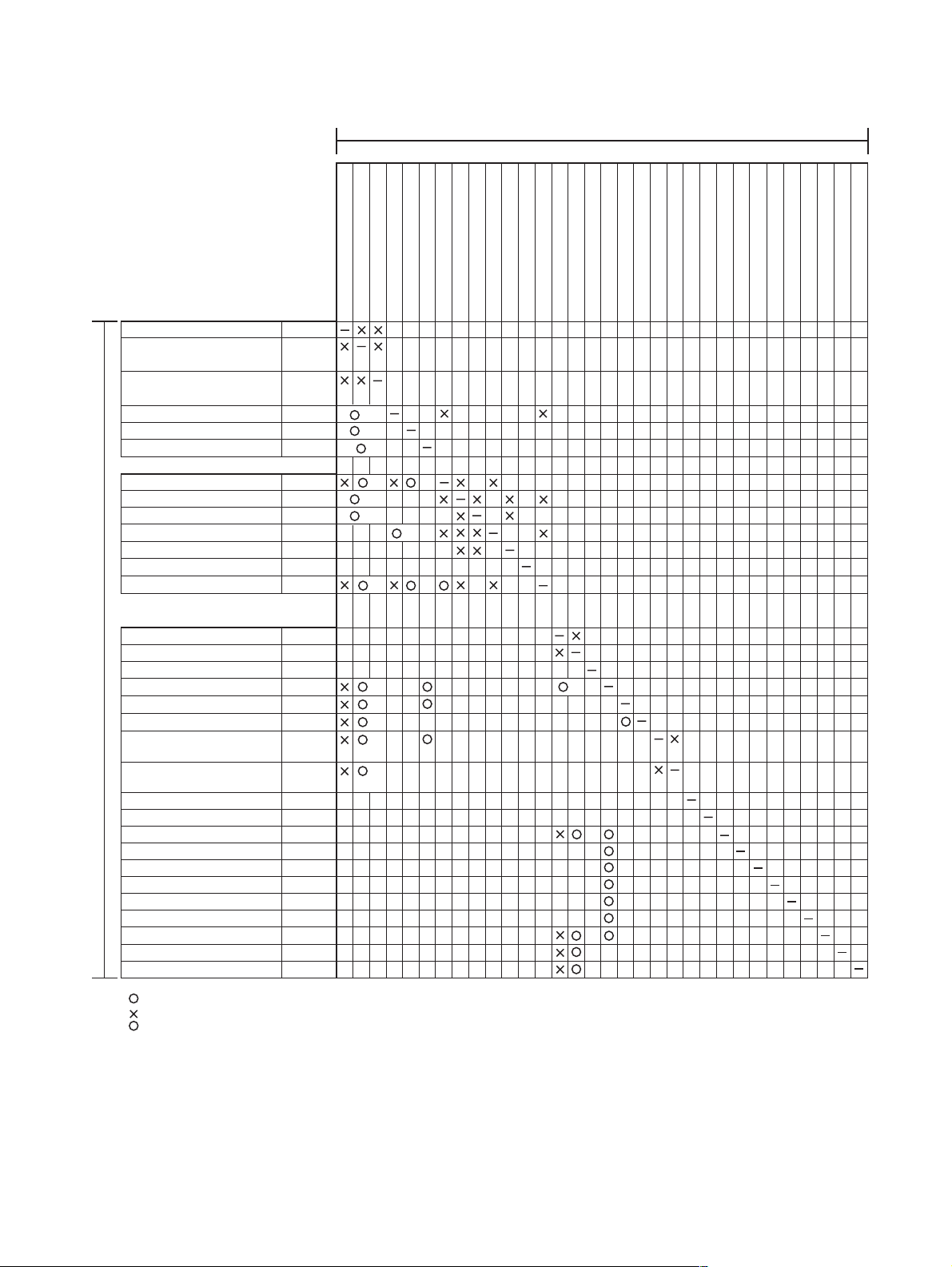
C. List of combination of peripheral devices
As shown in the table below, some other peripheral devices (B) may be needed for installation of a peripheral device (A) and some peripheral devices cannot be installed together.
B
xpansion kit
Related to paper feed unit
Multi purpose drawer
Stand/3 x 500 sheet
paper drawer
Stand/MPD & 2000 sheet
paper drawer
Duple
x module/bypass tray
Duplex module
Scanner module with DSPF
Output units
Saddle stitch finisher
Finisher
Mail-bin stacker
Exit tray
Upper e
xit tray
Punch unit
Related to extension of
functions and others
Network expansion kit
Network expansion kit (with HDD)
PS3 expansion kit
A
Network scanner expansion kit
Facsimile expansion kit
Fax memory (8 MB)
Data security kit
(For a model with HDD installed)
Data security kit
(For a model without HDD installed)
Bar code font
Flash ROM kit AR-PF2
Internet fax expansion kit
Sharpdesk 1 license kit
Sharpdesk 5 license kit
Sharpdesk 10 license kit
Sharpdesk 50 license kit
Sharpdesk 100 license kit
Application integration module
Application communication module
External account module
AR-MU2
AR-D27
AR-D28
AR-DU4
AR-DU3
MX-EFX1
AR-FN7
AR-FN6
AR-MS1
2
*
AR-TE3
AR-TE4
AR-TE5Right upper exit tray
AR-PN1
3
*
MX-NBX2
3
*
MX-NBX3
AR-PK6
MX-NSX1
AR-FX12
AR-MM9
MX-FRX6/
MX-FRX6U
MX-FRX7/
MX-FRX7U
AR-PF1
MX-FWX1
MX-USX1
MX-USX5
MX-US10
MX-US50
MX-USA0
MX-AMX1
MX-AMX2
MX-AMX3
Multi purpose drawer
Stand/3 x 500 sheet paper drawer
Stand/MPD & 2000 sheet
Duplex module/bypass tray
Duplex module
1
*
1
*
1
*
1
*
1
*
1
*
1
*
1
*
1
*
1
*
1
*
1
*
1
*
Saddle stitch finisher
Finisher
Mail-bin stacker
Scanner module with DSPF
Exit tray
Punch unit
Right upper exit tray
Upper exit tray
PS3 e
Network expansion kit
Network expansion kit (with HDD)
1
*
ax memory (8 MB)
Network scanner expansion kit
Facsimile expansion kit
F
Data security kit (For a model with HDD installed)
Flash ROM kit
Data security kit (For a model without HDD installed)
Bar code font
Internet fax expansion kit
Sharpdesk 1 license kit
Sharpdesk 5 license kit
Sharpdesk 10 license kit
Sharpdesk 50 license kit
Sharpdesk 100 license kit
Application integration module
Application communication module
External account module
= Must be installed together.
= Cannot be installed together.
*1 = Any of the units must be installed together.
*2 = The AR-DU4 is a standard provision.
*3 = Installable to the MX-M350U/M450U. The MX-NBX3 is a standard provision for the MX-M350N/M450N.
MX-M350/M450 N/U CONFIGURATION 2 - 4
Page 10
[3] SPECIFICATIONS
1. Basic Specification
A. Base Engine
(1) Form
Console type
(2) Engine speed
Paper size
A4, 8.5" x 11" 35ppm (31ppm*) 45ppm (40ppm*)
A4R, 8.5" x 11"R 25ppm 30ppm
A5R/5.5" x 8.5"R, Invoice-R 35ppm 45ppm
B5 35ppm 45ppm
B5R, Executive-R 25ppm 30ppm
B4/8.5" x 14" 20ppm 22ppm
A3/11" x 17" 17ppm 20ppm
8K 17ppm 20ppm
16K 35ppm 45ppm
* Paper feed from Manual bypass tray
MX-M350U/
M350N
(3) Engine composition
Photoconductor type OPC
Record method Electro-photograph (laser)
Development method Dry-type dual-component magnetic
Charge method Charged saw-tooth method
Transfer method Transfer roller
Cleaning method Counter blade
Fusing method Heat roller
(diameter of photoconductor : ø30mm)
brush development
(4) Engine resolution
Resolution Read: 600dpi x 600dpi
Smoothing Write: 1200dpi equivalent x 600dpi
Gradation Write: 2 levels
Write: 600dpi x 600dpi
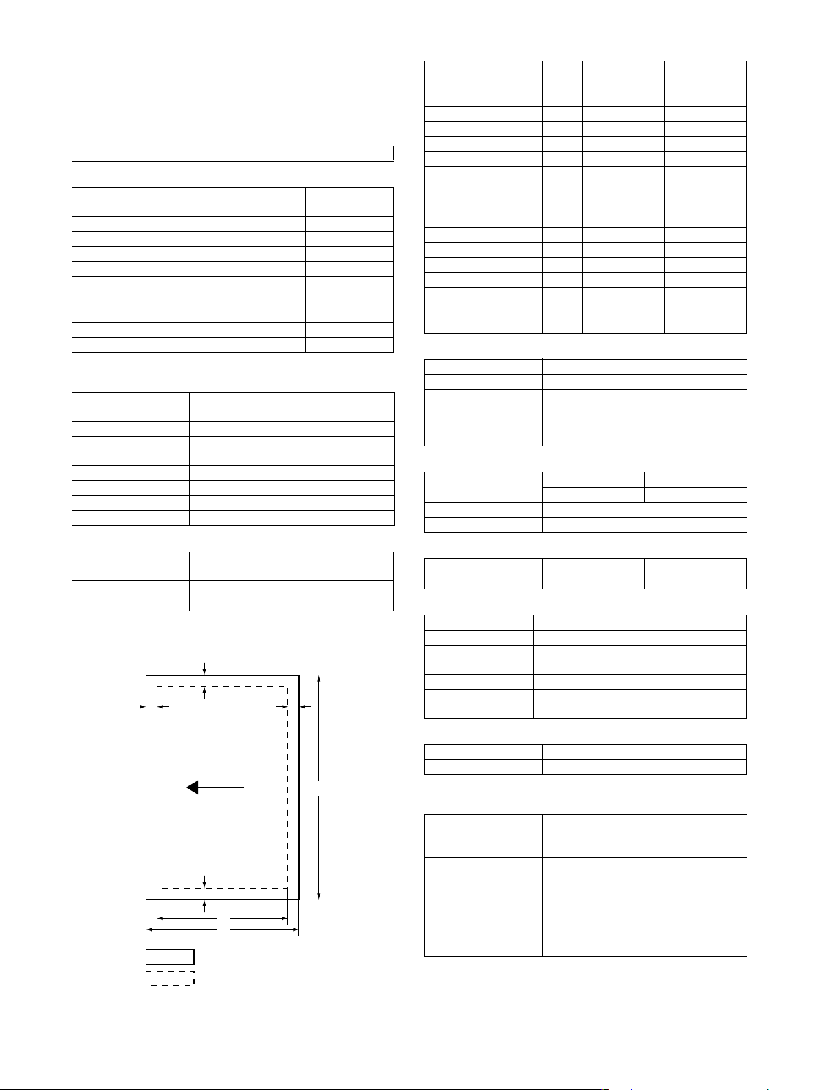
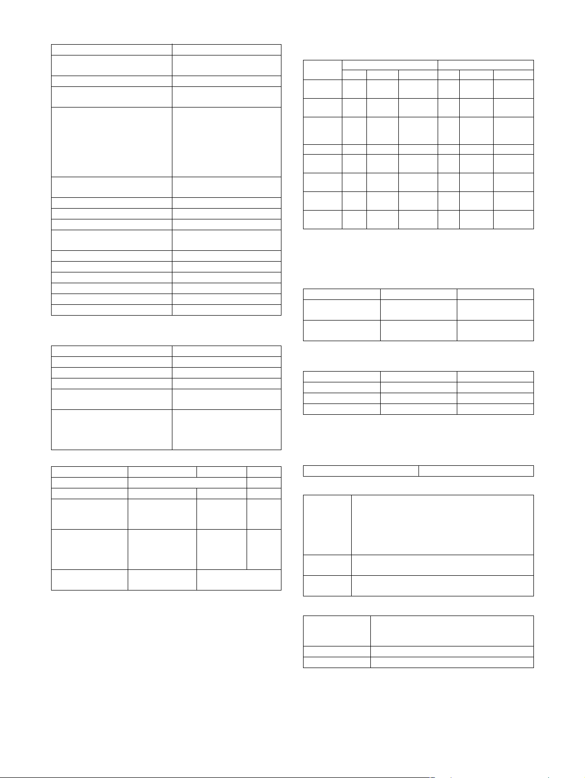
(5) Printable area
The print area of this product is shown below.
E
C
E
D
C
A
Paper size
Printable area
MX-M450U/
M450N
B
(in mm)
Paper size A B C D E
A3 297 420 4 289 4
B4 257 364 4 242 4
A4 210 297 4 202 4
B5 182 257 4 168 4
A5 148 210 4 140 4
Japanese postcard 100 148 4 92 4
Ledger 279 432 4 271 4
Legal 216 356 4 208 4
Foolscap 216 330 4 208 4
Letter 216 279 4 208 4
Executive 184 267 4 183 4
Invoice 140 216 4 132 4
Com-10 (envelope) 105 241 4 97 4
C5 (envelope) 162 229 4 154 4
Monarch (envelope) 98 191 4 90 4
DL (envelope) 110 220 4 102 4
ISO B5 (envelope) 176 250 4 168 4
(6) Warm-up
Warm-up time less than 80 seconds
Pre-heat requirement Required
Jam recovery time Target: about 30 seconds
(Under standard condition of 60
seconds left after side cover opening,
polygon motor halt)
(7) Power source
Voltage current 100V system 200V system
100-127V, 12A 220-240V, 8A
Frequency 50/60Hz
Power cord Inlet type
(8) Power consumption
Max. Power
consumption
100V 1440W
200V 1850W
(9) Energy Star benchmark
MX-M350U/M350N MX-M450U/M450N
Low power mode 184.75W 223.25W
Recovery time from
low power mode
Sleep mode Less than 80W Less than 95W
Transition time to
sleep mode
Max. 30 sec. Max. 30 sec.
60 min. 60 min.
(10) Noise
At working less than 6.8dB
At waiting mode less than 5.0dB
∗ Showing noise benchmark in each model as a whole system.
(11) Dimensions
External dimensions
(W x D x H)
Occupied space
dimensions
(W x D)
Weight Engine: Approx. 85.8 lb (38.9 kg)
33-1/16" x 26-11/64" x 44-23/64"
(840 mm x 665 mm x 1127 mm)
(including automatic document feeder)
38-3/16" x 26-11/64" (970 x 665 mm)
(Include automatic document feeder)
Desk: Approx. 72.6 lb (32.9 kg)
Rack: Approx. 16 lb (7.4 kg)
DSPF: Approx. 46 lb (21 kg)
If a printer driver for Windows or Macintosh is used for printing, the
printable area will be smaller. The actual printable area depends
on the printer driver to be used.
MX-M350/M450 N/U SPECIFICATIONS 3 - 1
Page 11

B. Document Feeding Equipment
(1) One-drawer tray (included in the base engine)
Paper feed method One-drawer tray
Sizes to be fed A4, B5, 8.5" x 11"
Paper capacity 500 sheets (at 80g/m²)
Media available for
paper feeding
Paper type Normal, recycled, pre-printed, pre-
Paper size switching To be switched by user
Dehumidification
heater
Balance detection Provided (paper empty and 3 steps)
Default size setting 100V system
Mounting/demounting
of the tray
Plain paper 60 - 105g/m², 16 - 28lbs
punched, color, letter head
(paper size to be entered from the
operation panel).
Not available
8.5" x 11"
Provided
C. Output Equipment
(1) Face-down Exit Tray (included in the base engine)
Output position/
method
Output paper capacity 400 sheets (80g/m² sheet)
Output paper size A3, B4, A4, A4R, B5, B5R, A5R
Spec of media for
paper output
Remaining paper
detection
Exit tray full detection Provided
Face-down output at the upper side of
main unit
11 " x 17", 8.5" x 14", 8.5" x 13",
8.5" x 11", 8.5" x 11"R, 5.5" x 8.5"R
Executive, Japanese post card,
Monarch (98 x 191), 8K, 16K, 16KR
Com-10 (105 x 241), DL (110 x 220),
C5 (162 x 229), ISO B5 (176 x 250)
Tracing paper: 52 ~ 59g/m² / 14 ~ 15lbs
Plain paper: 60 ~ 128g/m² / 16 ~ 34lbs
Index paper: 176g/m² / 47lbs
Cover paper: 205g/m² / 54 ~ 55lbs
Transparency firm
Not available
2. Specific Function
A. Printer Function
(1) Platform
IBM PC/AT (Include compatible machine)
Macintosh
(2) Support OS
Custom PS Windows 98/Me
Custom
PCL5e/6(XL)
PPD Windows 98/Me
GPD Windows Server 2003 x64
Windows NT 4.0 (Service Pack5 or later)
Windows 2000
Windows Server 2003
Windows XP
Windows Vista
Windows 98/Me
Windows NT 4.0 (Service Pack5 or later)
Windows 2000
Windows Server 2003
Windows XP
Windows Vista
Windows NT 4.0 (Service Pack5 or later)
Windows 2000
Windows Server 2003
Windows XP
Windows Vista
Mac OS 9.0 - 9.2.2, X 10.1.5, X 10.2.8,
X 10.3.9, X 10.4 - 10.4.8
Windows XP x64
Windows Vista x64
(3) PDL emulation
PCL6 compatible, PCL5e compatible, PostScript 3 compatible
(4) Windows driver function
a. General
Function PCL5e PCL6 PS
Copies 1-999
Orientation Portrait
Landscape
Duplex 1-sided
2-sided
(Left /top/ right
binding)
Booklet Invoice on Letter
Letter on Ledger
A5 on A4
A4 on A3
B5 on B4
Letter on Letter
Ledger on Ledger
A4 on A4
A3 on A3
B4 on B4
Binding edge Left / top / right –
N-up 2/4/6/8/9/16 2 / 4 / 6 / 9 / 16
N-up order Z / Reversed Z /
N / Reversed N
N-up border Yes / No Always Yes (*2)
*1: For printing, PS driver bundled with the Windows is required.
*2: Since the function is of PS driver bundled with Windows, spec-
ification may vary according to the OS.
PPD file *1
(for Windows XP)
Portrait
Landscape-A
Landscape-B
(*2)
1-sided
2-sided
(Long / short
binding)
(*2)
Ye s
(2up booklet only)
(*2)
(*2)
Z (*2)
MX-M350/M450 N/U SPECIFICATIONS 3 - 2
Page 12
b. Paper Input
Function PCL5e PCL6 PS
Paper size A3 / B4 / A4 / B5 /
Paper type Plain
Custom
paper type
Source
selection
Cover Yes/No
Insert page Yes/No
Transparency
inserts
*1: For printing, PS driver bundled with the Windows is required.
c. Paper Output
Function PCL5e PCL6 PS
Output tray
selection
Staple Finisher
Offset cancel Yes/No
*1: For printing, PS driver bundled with the Windows is required.
A5 / Ledger /
Legal / Foolscap /
Letter / Executive
/Invoice/8k / 16k
/COM10/C5/
Monarch/DL
Letter Head
Pre-Print
Pre-Punch
Recycle
Color
Label
Heavy Paper
Transparency
Envelope
7 type –
Automatic
Tray 1/2/3/4
Bypass-tray
User can select from
1-sided/2-sided/
No print
User can select from
1-sided/2-sided/
No print
No
Yes (Blank)
Yes (Printed)
Center tray
Finisher
• Top tray
• Offset tray
Saddle Stitch
Finisher
• Offset tray
Mailbin stacker
• Mailbin top tray
• Mailbin (1-7)
Duplex module
• Left tray
• No staple
•1 staple
• 2 staples
Saddle Stitch
Finisher
• No staple
•1 staple
• 2 staples
PPD file *1
(for Windows XP)
–
–
–
PPD file *1
(for Windows XP)
Saddle Stitch
Finisher
• No staple
• 1 staple
• 2 staples
d. Graphic
Function PCL5e PCL6 PS
Resolution
setting
Halftone
setting
Graphics
mode
Smoothing Yes/No
Toner save Yes / No
Photo
enhancement
Negative
image
Mirror image – – Horizontal
Zoom – – 25-400%
Fit to page Yes / No –
*1: For printing, PS driver bundled with the Windows is required.
*2: Since the function is of PS driver bundled with Windows, spec-
ification may vary according to the OS.
e. Font
Function PCL5e PCL6 PS
Download
font
*1: For printing, PS driver bundled with the Windows is required.
*2: Since the function is of PS driver bundled with Windows, spec-
ification may vary according to the OS.
f. Others
Function PCL5e PCL6 PS
Configuration
setting
Watermark Yes Yes
Line width
setting
Form overlay Yes –
Print hold Yes –
Confidential print Yes –
Sample print Yes –
Print accounting Yes –
Quick sets Yes –
Auto
configuration
Job end
notification
Tandem print Yes
Carbon print Yes –
Multienlargement
XY zoom – Yes –
Cover insert +
pamphlet
600/300 dpi 600dpi 600dpi
– No Screen frequency
Raster
HP-GL2
Bitmap
Tr u e Ty pe
Raster
Vec to r
–Yes/No – –
––Yes / No
Ye s
Ye s –
Ye s –
Ye s –
8.0 to 360.0
in 0.1 steps
Screen angle
0.0 to 360.0
in 0.1 steps
––
Ver ti cal
(XY zoom)
Bitmap
Type1
TrueType
–
–
PPD file *1
(for Windows
XP)
–
Horizontal
(*2)
1-1000%
(*2)
PPD file *1
(for Windows XP)
Auto
Outline
Bitmap
Native TrueType
(*2)
PPD file *1
(for Windows XP)
(functionality is
limited)
MX-M350/M450 N/U SPECIFICATIONS 3 - 3
Page 13
Function PCL5e PCL6 PS
Document filing Yes
(MX-M350U/M450U: The
MX-NBX3 is required.)
*1: For printing, PS driver bundled with the Windows is required.
PPD file *1
(for Windows XP)
–
(5) Macintosh driver functions
a. General
Function
Copies 1-999
Orientation Portrait
Landscape-A
Landscape-B (*1)
Duplex 1-sided
Booklet Yes
N-up 2/4/6/9/16 (*1)
N-up order Z / reversed Z / N / reversed N (*1)
N-up border None / Single hairline / Single thin line /
*1: Since the function is of PS driver bundled with Macintosh,
specification may vary according to the OS.
b. Paper input
Function
Paper size A3 / B4 / A4 / B5 / A5 /
Paper type Plain / Letter Head / Pre-Print /
Custom paper
type
Source selection Automatic
Different 1st
page
Cover / insert
page
Transparency
inserts
*1: Since the function is of PS driver bundled with Macintosh,
specification may vary according to the OS.
2-sided
Pamphlet
(Right /left /top binding)
Double hairline / Double thin line (*1)
Japanese Postcard /
Ledger / Legal / Foolscap / Letter /
Executive / Invoice/ 8K / 16K/
COM10/C5/Monarch/DL
Pre-Punch / Recycle / Color /
Label / Heavy Paper / Transparency /
Envelope
7
Tray 1/2/3/4
Bypass-tray
Yes / No (*1)
–
(On OS9, user can select from: No/First
Page/Last Page)
(*1)
No
Yes (Blank)
Yes (Printed)
Macintosh PPD file
(for Mac OS X ver10.2.8)
Macintosh PPD file
(for Mac OS X ver10.2.8)
c. Paper output
Function
Output tray
selection
Staple Finisher
Offset Yes/No
d. Graphic
Function
Resolution setting 600dpi
Halftone setting –
Graphics mode –
Smoothing Yes/No
Toner save Yes / No
Photo enhancement Yes/No
Negative image –
Mirror image –
Zoom 1-100000 (*1)
Fit to page –
*1: Since the function is of PS driver bundled with Macintosh,
specification may vary according to the OS.
e. Font
Function
Download font –
f. Others
Function
Configuration setting Yes
Watermark Yes
Form overlay –
Print hold Yes
Confidential print Yes (PIN selection)
Sample print Yes
Print accounting Yes
Quick sets –
Auto configuration – (OS9: Yes)
Job end notification –
Tandem print Yes
Carbon print –
Multi-enlargement –
XY zoom –
Cover insert + pamphlet –
Document filing Yes (*1)
*1: Since the function is of PS driver bundled with Macintosh,
specification may vary according to the OS.
Center tray
Finisher
•Top tray
• Offset tray
Saddle Stitch Finisher
• Offset tray
Mailbin stacker
• Mailbin top tray
• Mailbin (1-7)
Duplex module
• Left tray
• No staple
• 1 staple
• 2 staples
Saddle Stitch Finisher
• No staple
• 1 staple
• 2 staples
(Selectable only on MacOS9.x.x LaserWriter) (*1)
Macintosh PPD file
(for Mac OS X ver10.2.8)
Macintosh PPD file
(for Mac OS X ver10.2.8)
Macintosh PPD file
(for Mac OS X ver10.2.8)
Macintosh PPD file
(for Mac OS X ver10.2.8)
(MX-M350U/M450U: The MXNBX3 is required.)
MX-M350/M450 N/U SPECIFICATIONS 3 - 4
Page 14
(6) Compatibility
PCL5e
compatibility
PCL6
compatibility
PostScript
Compatibility
PCL5e is compatible with HP LaserJet 4050.
Small margin difference, rendering difference by
different font family, default and transfer function
difference is not to be included in the compatibility.
PCL6 is compatible with HP LaserJet 4050.
Small margin difference, rendering difference by
different font family, default and transfer function
difference is not to be included in the compatibility.
Must be compatible with Adobe PostScript.
Small margin difference, rendering difference by
different font family, default and transfer function
difference is not to be included in the compatibility.
B. Image send function
(1) Mode
Scanner Scan to e-mail
Fax Fax
Internet Fax Internet Fax (Full mode support)
* PC-FAX/PC-Internet-Fax is allowed.
(2) Support system
Mode Scanner Internet Fax FAX
Supported
server/
protocol
(3) Support image
Mode Scanner Internet Fax FAX
File format TIFF, PDF TIFF-FX
Compression
method
(4) Image process
Mode Scanner Internet Fax FAX
Half tone
reproduction
Exposure
adjustment
Quality
selection
Resolution
(Varies with
the file type/
transmission
method)
Scan to Desktop
(Scan data send which is not dependent on IP
addresses under DHCP environment)
Scan to FTP
Scan to Folder (SMB)
Scan to e-mail with Meta
Scan to Desktop with Meta
Scan to FTP with Meta
Scan to SMB with Meta
Fax to e-mail (Inbound Routing)
Fax to FTP/Desktop/SMB/e-mail
(Document Admin)*
Internet Fax to e-mail
(Inbound Routing) (HDD)
Internet Fax to FTP/Desktop/SMB/e-mail
(Document Admin)*
SMTP
FTP (TCP/IP)
SMB
Uncompressed,
G3 (1-dimension) = MH
(Modified Huffman)
G4 = MMR (Modified MR)
Half-tone ON/OFF (It's not effective for the
following resolution with *.)
200 x 200dpi Normal * Normal
200 x 200dpi Small letter Small letter
300 x 300dpi Fine Fine
400 x 400dpi Extra fine Extra fine
600 x 600dpi 600 x 600dpi –
POP server
SMTP server
ESMTP server
(TIFF-F)
MH, MMR MH, MR,
Equivalent to 256 levels
Auto + 5 steps
(203.2 x 97.8dpi)*
(203.2 x 195.6dpi)
(203.2 x 391dpi)
(406.4 x 391dpi)
–
MMR,
JBIG
(5) Specified destination
Mode Scanner Internet Fax FAX
Specified
destination
One-touch keys
(Max. number of
keys to be
stored.)
Number of
Group (1 key)
address
registration
Program Yes (8 programs)
Manual
destination entry
Chain dialing
Resend Call up nearest 1 addresse which are
Speed dialing
(quick key)
CC / BCC
sending
Subject Selective/direct entry from
File name Selective/direct entry from
Sender name
Transmitter's
name
*1: Model without HDD installed
Specifying by one-touch or group, manual
Entry from soft keyboard. (Scanner/Internet
In this, FTP, Desktop, and SMB are 200
Entry from soft keyboard.
This is used to recall address control number
Ye s –
Yes (Selective/
direct entry
from the list /
selection from
LDAP server)
destination entry
Entry from 10-key. (Fax)
Selection from LDAP server
Max. 999 (500
Max. 500 (300
specified as a single destination.
by using numeric keys.
the list
the list
–
Fax)
Resend
Quick
*1
) destinations
*1
(100
) destinations.
*1
) destinations
Input via the
numeric
keys, # key
– Up to 64-digit
(1 default address fixed as
sender name)
and * key.
with pause key.
No
–
–
(6) Specified multiple destinations
–
Mode Scanner Internet Fax FAX
Specified
destination
Max. number
of Manual
destination
entry*
Sequential
broadcasting
Simultaneous
FAX
transmission
*1: Model without HDD installed
* Manual destination entry: Entry other than One-touch, using
numeric keys or soft keyboard.
* In the case of broadcast transmission including fax destina-
tion, the resolution level for fax mode is applied.
* In the case of broadcast transmission with Internet Fax and
Scanner destinations, the resolution level of Internet Fax mode
is applied.
* In the case of broadcast transmission, the compression format
set with the system settings is applied.
Specifying by one-touch or group, manual
destination entry.
Total of 5000 (100
group and relay broadcast.
Yes (E-mail only. It is not
available for
FTP/Desktop/SMB.)
*1
) destinations including
Ye s
–Yes
MX-M350/M450 N/U SPECIFICATIONS 3 - 5
Page 15
(7) Functions
Mode Scanner Internet Fax FAX
Transmit
function
Receive
function
*1: Model without HDD installed
Memory transmit –
On-hook – Yes
Quick online
transmit
Manual transmit – At on-hook
Auto reduction
transmit
Rotation transmit Yes (Manual) Yes (Auto)
Scaling transmit Yes (Scaling from regular size to regular
Re-call
mode
Book original
transmit
Long length
original transmit
Specified pages
per file
Maximum number
of send data
Sender name Max. 999 (500
Address
Confirmation
Function
(Prevention of missend)
Auto receive – Yes
Manual receive – Yes
Memory receive – Yes
Reduction receive
for standard size
Rotation receive – Yes
Divided receive – Yes: To be defined by
Duplex receive – Yes: To be defined by
2 in 1 receive –
Address/Domainspecified reception
is enabled.
Address/Domainspecified reception
is disabled.
Reception refusal
setting of Specific
number
External phone
connection
Transfer function at
output trouble
Auto startup mode – Yes
Error – Yes
Busy – – Yes
Data is sent
by memory
transmit
when upper
limit is set.
–Yes
–Yes: A3 → B4,
size only.
Some functions does not allow rotation
transmit)
No. of times/interval is set via system
settings.
Ye s Ye s Ye s
Max. 800mm
Ye s –
Ye s –
–Yes
–Yes
–Yes (50
address)
–Yes (50
address)
–Yes (30
–Yes
–Yes
Ye s
A3 → A4,
B4 → A4
Ye s
*1
) destinations
(Soft SW)
system settings
system settings
destinations)
only
Mode Scanner Internet Fax FAX
Special
function
Report/
List
function
Others PC-facsimile
Time setting Yes
Transmit request – Yes
Remote transmit – Yes
Cover function – No
Print at sender – Yes –
Page division Yes
Confidential
(machine at the
other end)
Transmit broadcast
direction
Edge erase Yes
Center erase Yes
2 in 1 Yes
Card shot Yes
Transmit/receive
record
Transmit/receive
result
Address/phone
directory list
Group list Yes
Sender list Print
Program list Yes
Memory box list – Yes (FAX
Memory clear
notice list
Rejected Number
List
Receiving setting
address list
List of Transfer
tables to E-mail
List of transfer
tables to
administrator
Web setting list Yes
transmission
administrator
address.
(It's possible that this is output in case of
– Yes (F code
– Yes (F code
Ye s
No Yes
Ye s
Described in the system
–
errors.)
–Yes
–Yes –
Yes (HDD)
Ye s
– PC-Internet
Fax
method)
method)
No
settings list
mode only)
PC-FAX
(8) Transmission method
Mode FAX
Transmission time 2 seconds (level: Super G3/JBIG)
6 seconds (G3 ECM)
–
Modem speed 33.6kbps → 2.4kbps automatic fallback
Intercommunication Super G3/G3
Communication line General telephone line (PSTN), Private
–
Number of
branch exchange(PBX), FAX line
R-key for PBX setting: Germany, France
1 line only
maximum
communication line
ECM Yes
(9) Record size
Mode Internet Fax FAX
Max. record
293mm
width
Record size A3-A5,
11" x 17" - 5.5" x 8.5"
(10) F code transmission
Mode FAX
Sub address Yes
Passcode Yes
MX-M350/M450 N/U SPECIFICATIONS 3 - 6
Page 16
(11) Registration-related settings
Item Registerable Number
Individual/ Group 999 (Up to 500 can be
registered for 1 group.)
Program 8
Memory box Total 100 of Polling Memory/
Confidential/Relay Broadcast
Scheduled send job 94
(Manual transmit: 1, Manual
forwarding: 1,
Manual Internet Fax
forwarding: 1, Inbound
Routing and Document
Admin : total 3 Total: 100)
Own number and Name Set Internet Fax: 1
Fax: 1
User list (Reply-to List) 999 (500
*1
)
Inbound Routing List 50
Inbound routing addresses 1000
Sender Number/Address
500
Registration (Inbound Routing)
Subject (Send Settings) 30
File name (Send Settings) 30
Metadata Set List 10
Rejected Number 50
Rejected Address 50 (30
*1
)
Polling permitted Number 10
*1: Model without HDD installed
(12) Telephone Functions
Mode Fax
Speaker Yes
Hold No
Setting of pause time Yes (1-15 seconds)
Telephone transmission during
power outage
No (External telephone
transmission allowed)
Tone pulse switching Existence of settings for 10/
20/TONE/Auto Select and
their default values depends
on destinations.
(13) Others
Mode Scanner Internet Fax Fax
PC- FAX – Yes
PC-Internet Fax – Yes --FAST – – Yes
(SEC
only)
Trial mode Yes (Included
meta data. These
can be set up
separately.)
Linearrized PDF Support by Net
Scan Tool
No –
–
C. Copy function
(1) Copy Speed
MX-M350U/M350N MX-M450U/M450N
A4,
8.5" x 11"
A4R,
8.5" x 11"R
A5R,
5.5" x 8.5"R,
Invoice-R
B5 35 35 35 45 45 45
B5R,
Executive-R
B4,
8.5" x 14"
A3,
11" x 17"
Extra,
Envelope
∗ Figures in reduction/enlargement are represented by those at
the ratio to show slowest speed
(2) First copy time
Conditions: A4 or 8.5"x11" from front tray of PPC, with polygon
Document glass *1 Less than 4.9
DSPF Less than 6.0
*1: During OC mode
(3) Job speed
S→ S *1 33 cpm (94%) 42 cpm (93%)
S→ D *2 32 cpm (91%) 40 cpm (88%)
D→ D *3 32 cpm (91%) 40 cpm (88%)
*1: S → S : A4 / 8.5" x 11" original 5 sheets copy 5sets
*2: S
*3: D
(4) Continuous copy
Max. multiple number 999 pages
(5) Copy Ratio
Copy ratio AB series :
Zoom 25 - 400%
Independent
scaling
Actual Reduction Enlargement Actual Reduction Enlargement
35 35 35 45 45 45
25 25 25 30 30 30
35 35 35 45 45 45
25 25 25 30 30 30
20 20 20 22 22 22
17 17 17 20 20 20
17 17 17 20 20 20
motor running.
MX-M350U/M350N MX-M450U/M450N
Less than 4.4
seconds
seconds
Less than 5.3
seconds
seconds
MX-M350U/M350N MX-M450U/M450N
→
D : A4 / 8.5" x 11" original 10 sheets copy 5sets
→
D : A4 / 8.5" x 11" original 5 sheets (10 pages) copy 5sets
25%, 50%, 70%, 81%, 86%, 100%, 115%, 122%,
141%, 200%, 400%
Inch series :
25%, 50%, 64%, 77%, 100%, 121%, 129%, 200%,
400%
25 - 200% (Copy from DSPF)
4
(6) Exposure/Copy Quality Process
Exposure mode Binary: Text(auto/manual), Text/photo, Photo,
Manual steps 9 steps
Toner save mode Yes (Except for U.K.), Default: OFF
MX-M350/M450 N/U SPECIFICATIONS 3 - 7
Auto
256 levels: Not provided
Page 17
(7) Copy Function
Function APS Yes
AMS Yes
XY zoom Yes
Paper type select Yes (By type setting)
Auto tray switching Yes
Rotation copy Yes
Electronic sort Yes
Rotation sort Yes (Europe, Australia,
Reserved copy Yes (99 destinations)
Recall/register of program Yes (10 destinations)
Document filing Yes
Preheat function Yes (To be set up by the
Auto power shut-off
function
Account control Yes (500 accounts)
Process control Yes
Tandem copy Yes (Network interface's
Book copy Yes
Irregular original size input Yes
Irregular paper size input Yes (Tray 2/Manual tray)
Mixed originals feeder Yes (MIX only)
Special
function
Margin shift Yes (Left/Right)
Edge erase/Center erase Yes (Center/Edge/Center
Dual page copying Yes
Covers/Inserts/Tab paper
insertion
Transparency insert Yes
Multi shot (Nin1) Yes (2 in 1 / 4 in 1)
Card shot Yes (Centering: Yes)
Pamphlet copy Yes (Centering: Yes)
2-sided copy orientation
change
Job build HDD model: Max.10,000
Negative image Yes
Shading No
Black-white inversion Yes (Except UK)
Mirror image Yes
Multi-page enlargement No
Repeat No
Date stamp Yes
Stamp Yes
Character stamp Yes
Page stamp Yes
Yes: Standard Function
No: Not available
Agency)
(MX-M350U/M450U: The
MX-NBX3 is required.)
system settings)
Yes (To be set up by the
system settings)
being unnecessary)
+ Edge)
Ye s
(Centering: Yes)
Ye s
sheets
HDD uninstallation model
is decided by memory
retention.
Scaling, Density and
Paper for each bunch are
possible to be changed.
3. B/W Scanner Module (DSPF)
(1) Form
Scanner (Document glass) / DSPF standard
Operation panel integral type
(common hardware for all the destinations)
(2) Resolution / Gradation
Reading resolution (dpi)
Magnification 25 - 99 100
OC 600x600 600x600 600x600 600x1200 –
OC
(High speed):
Text/Auto
OC
(High speed):
Others
DSPF/SPF
(standard)
DSPF/SPF
(high quality)
Input and transmitting resolution (dpi)
FAX transmit mode and scanner/fax multicasting mode
Selection
mode
Input
resolution: OC
Input
resolution:
DSPF
Transmitting
resolution
Internet-FAX
Transmitting
resolution
Scanner mode
Selection
mode
Input
resolution: OC
Input
resolution:
DSPF
Transmitting
resolution
Reading level
256 tones
Exposure lamp
Electrodeless xenon lamp
Output level
Binary
600x600 600x600 600x600 600x1200 –
600x600 600x300 600x600 600x1200 –
600x300 600x300 600x600 - –
600x600 600x600 600x600 - –
Standard Fine Super fine Ultra fine 600dpi
600x600 600x600 600x600 600x600 –
600x300 600x300 600x300 600x300 –
203.2x97.8 203.2x195.6 203.2x391 406.4x391 –
200x100 200x200 200x400 400x400 600x600
Standard Fine Super fine Ultra fine –
600x391.2 600x391.2 600x391.2 600x600 –
600x300 600x300 600x300 600x300 –
200x200 300x300 400x400 600x600 –
(3) Document Glass
Reading area 297 x 431.8 (mm)
Original
alignment
Original size
detection
Sizes to be
detected
11.7" x 17"
Left edge / Rear corner alignment
Provided
(Standard size only)
Automatic (one detection unit to be used with
software modification by destination)
Inch-1 11" x 17", 8.5" x 14", 8.5" x 11",
Inch-2 11" x 17", 8.5" x 13", 8.5" x 11",
AB-1 A3, B4, A4, A4R, B5, B5R, A5
AB-2 A3, A4, A4R, A5, B5, B5R,
AB-3 8K, A4, A4R, A5, B4, 16K,
Copy mode
101 - 171
(DSPF/
SPF (high
quality):
101 - 200))
8.5" x 11"R, 5.5" x 8.5"
8.5" x 11"R, 5.5" x 8.5"
216 x 330 mm
16KR
172 - 400 –
sending
MX-M350/M450 N/U SPECIFICATIONS 3 - 8
Page 18
OR guide
display
Rear left side
(Print display)
Left side OR
guide
(Print display)
Interior side OR
guide
(Print display)
Interior side OR
guide
The position available to attach the staple
position guide label when the optional finisher
(desktop console type) is equipped.
Original reference position " "
(From the Interior side)
5-1/2, A5R, B5R, A4R/A5,
8.5", B4R/B5, 11", A3R/A4
(From the left side)
5-1/2, A5, B5, A4/A5R, 8-1/2,
B5R, 11", A4R, 13", 14", B4R,
A3R, 17"
Book marks are at A4 and
8-1/2 positions.
(4) DSPF/SPF
Type DSPF One-scan-dual-side scanning
method DSPF with OC
integrated
Scan speed Standard mode 45 opm
High quality mode 22.5 opm
Original
alignment
Original size A3, B4, A4, A4R, B5, B5R, A5, A5R
Original
paper
weight
Original
stack
capacity
Not
transportable
original type
Original size
detection
Sizes to be
detected
Original tray
guide
display
Center alignment
11"x17", 8.5"x14", 8.5"x13", 8.5"x11", 8.5"x11"R,
5.5"x8.5", 5.5"x8.5"R, 8K, 16K, 16KR
(Long size original up to 800mm in FAX, e-mail and
Internet Fax mode)
50~128g/m², 15~34lbs
Max. 50 sheets
(Max. 30 sheets for A3, B4,11" x 17",8.5" x 14")
(Max. 15 sheets for A3, B4, 11" x 17", 8.5" x 14"
over 105g/m²)
or, Total thickness less than
Max. 6.5mm (at 50 to 80g/m², 15 to 21lbs)
Max. 5.0mm (at 80 to 128g/m², 21 to 34lbs)
Transparency film, secondary original paper,
tracing paper, carbon paper, thermal paper,
original with crumple/crimp/rip,
original with attachment/clipping,
original with many punch holes
(with 2 or 3 holes acceptable),
original preprinted with ink-ribbon,
Documents with considerable curl.
Provided
Automatic (one detection unit to be used with
software modification by destination)
Inch-1 11" x 17", 8.5" x 14", 8.5" x 11",
8.5" x 11"R, 5.5" x 8.5", A4, A3
Inch-2 11" x 17", 8.5" x 13", 8.5" x 11",
8.5" x 11"R, 5.5" x 8.5", A4, A3
AB-1 A3, B4, A4, A4R, B5, B5R, A5,
AB-2 A3, B4, A4, A4R, B5, B5R, A5,
AB-3 8K, A4, A4R, B4, 16K, 16KR,
Center of the tray
(inscribed symbol)
Original Guide
(inscribed symbol)
The position available to attach the staple position
guide label when the optional finisher (desktop
console type) is equipped.
A3, 8.5" x 11", 11" x 17",
216 x 330 mm
8.5" x 11", 11" x 17",
216 x 330 mm
8.5" x 11", 216 x 330 mm
Original reference position " "
Original face-down placement
indication " "
(From Center)
B5R, A4R/A5, 8.5",
B4R/B5, 11", A3R/A4
(5) Power Source
Supplied from the main unit
(6) Dimensions
External dimensions
(WxDxH)
Occupied space
dimensions (WxD)
Weight DSPF: Approx. 47 lbs (21.2 kg)
840 x 665 x 1127 mm
(33-1/16" x 26-11/64" x 44-23/64")
(Includes a scanner unit)
1043 x 665 x 1127 mm
(41-1/16" x 26-11/64" x 44-23/64")
(For machine with AR-DU4)
970 x 665 mm (38-3/16" x 26-11/64")
(When the tray is extended)
(7) Display device at scanner part
Type Dot map LCD, touch panel
Display dot number 640 x 240 dots (H-VGA)
LCD operating dimension 192 x 79 mm (7-35/64 x 3-7/64 inch)
LCD back-light Fluorescent tube method
LCD brightness adjustment Provided
Operation panel LCD Monochrome H-VGA 8.9 inch
(dot pitch 0.24 x 0.24 mm)
(8) Key
Mode
selection
area
Basic input
area
* For printer
Job status key
Document filing key or Printer key
(* online display LED/data in-memory display LED)
Image send key
(busy display LED/data in-memory display LED)
Copy mode key
System settings key
Start key
CA key
10-key
Clear key
∗ key
#/P key
(9) Used character in the LCD
Dot 8 x 16 , 16 x 16 dots
Bold display O
(10) Touch sense method
Resistive film method
4. Rack for Scanner
(1) Dimensions
Strength 60 kg
Weight Approx. 16.3 (7.4 kg)
MX-M350/M450 N/U SPECIFICATIONS 3 - 9
Page 19

[4] CONSUMABLE PARTS
1. Supply system table
A. USA/Canada
No. Item Content Life Model name Remarks
1 Toner cartridge (Black) Toner cartridge (with IC)
(Toner : Net weight 750 g)
2 Developer (Black) Developer
(Developer : Net weight 500 g)
3 Drum OPC drum x1 200K AR-455DR
B. European Subsidiary/East Europe/Russia/Australia/New Zealand
No. Item Content Life Model name Remarks
1 Toner Cartridge (Black) Toner CA with IC Chip
(Toner; Net Weight 750g)
2 Developer (Black) Developer
(Developer; Net Weight 500g)
3 Drum Drum x 1 200K AR-455DM
C. Taiwan (Aurora)
No. Item Content Life Model name Remarks
1 Toner Cartridge (Black) Toner CA with IC Chip
(Toner; Net Weight 750g)
2 Developer (Black) Developer
(Developer; Net Weight 500g)
3 Drum Drum x 1 200k AR-455DM
D. Asia
No. Item Content Life Model name Remarks
1 Toner Cartridge (Black) Toner CA with IC Chip
(Toner; Net Weight 750g)
2 Developer (Black) Developer
(Developer; Net Weight 500g)
3 Drum Drum x 1 200K AR-455DR
E. Middle East/Africa/Israel/Philippines
No. Item Content Life Model name Remarks
1 Toner Cartridge (Black) Toner CA with IC Chip
(Toner; Net Weight 750g)
2 Developer (Black) Developer
(Developer; Net Weight 500g)
3 Drum Drum x 1 200k AR-455DR
F. Hong Kong
No. Item Content Life Model name Remarks
1 Toner Cartridge (Black) Toner CA with IC Chip
(Toner; Net Weight 750g)
2 Developer (Black) Developer
(Developer; Net Weight 500g)
3 Drum Drum x 1 200k AR-455DR-C
G. China
No. Item Content Life Model name Remarks
1 Toner Cartridge (Black) Toner CA with IC Chip
(Toner; Net Weight 750g)
2 Developer (Black) Developer
(Developer; Net Weight 500g)
3 Drum Drum x 1 200k AR-455DR-C
x 10 350K
(35K x 10)
x 10 1000K
(100K x 10)
x 10 350K
(35K x 10)
x 10 1,000K
(100K x 10)
x 10 350k
(35k x 10)
x 10 1,000k
(100K x 10)
x 10 350K
(35K x 10)
x 10 1,000K
(100K x 10)
x 10 350K
(35K x 10)
x 10 1,000k
(100K x 10)
x 10 350K
(35K x 10)
x 10 1,000K
(100K x 10)
x 1 35k AR-456ST-C *Life : A4 size at Area Coverage
x 1 100k AR-455SD-C
AR-455MT *Life setup is based on A4 6%
AR-455MD
AR-455LT *Life: A4 size at Area Coverage
6%
AR-455LD
AR-455ET *Life : A4 size at Area Coverage
6%
AR-455LD
AR-455CT *Life: A4 size at Area Coverage
6%
AR-455CD
AR-455ET *Life : A4 size at Area Coverage
6%
AR-455CD
AR-455CT-C *Life : A4 size at Area Coverage
6%
AR-455CD-C
6%
MX-M350/M450 N/U CONSUMABLE PARTS 4 - 1
Page 20

2. Maintenance parts list
A. USA/Canada
No. Item Content Life Model name Remarks
1 200K Maintenance kit Cleaner blade x 1 200K AR-455KA1 *1:Screen grid, charging plate, MC
Drum separation pawl x 4
MC unit *1 x 1
Toner receiving seal x 1
Side malt F x 1
Side malt R x 1
Transfer roller x 1
Discharge plate x 1
Paper dust removing unit x 1
DV blad e x 1
DV side seal F x 1
DV side seal R x 1
2 Upper heat roller kit Upper heat roller x 1 200K AR-455UH
Fusing separation pawl (Upper) x 4
3 Lower heat roller kit Lower heat roller x 1 200K AR-455LH
Fusing separation pawl (Lower) x 2
4 Cleaner blade Cleaner blade x 10 200K (x 10) AR-455CB AR-455CB = (AR-455BL) x 10
5 Cleaning roller kit Cleaning roller x 10 200K (x 10) AR-455CR AR-455CR = (AR-455RC) x 10
Bearing x 20
6 Staple cartridge Staple cartridge x 3 3000 times x 3 AR-SC1 Cartridge for AR-FN4
7 Staple cartridge Staple cartridge x 3 5000 times x 3 AR-SC2 Cartridge for AR-FN7
B. Europe/Australia/New Zealand/Taiwan
No. Item Content Life Model name Remarks
1 200K PM kit Cleaner blade x 1 200K AR-451KA *1: Screen grid, charging plate, MC
Drum separation pawl x 4
MC unit *1 x 1
Toner receiving seal x 1
Side malt F x 1
Side malt R x 1
Transfer roller x 1
Discharger plate x 1
Paper dust removing unit x 1
DV blad e x 1
DV side seal F x 1
DV side seal R x 1
Upper heat roller x 1
Fusing separation pawl (Upper) x 4
Lower heat roller x 1
Fusing separation pawl (Lower) x 2
Cleaning roller x 1
Bearing x 2
2 Staple cartridge Staple cartridge x 3 3000 times x 3 AR-SC1 Cartridge for AR-FN4
3 Staple cartridge Staple cartridge x 3 5000 times x 3 AR-SC2 Common with cartridge for AR-FN7
Note: The other maintenance parts which are not listed above are registered as service parts.
cleaner unit are included.
Common with cartridge for AR-FN6
cleaner unit are included.
Common with cartridge for AR-FN6
MX-M350/M450 N/U CONSUMABLE PARTS 4 - 2
Page 21

C. Agency/Asia/Middle East/Africa/Latin America
No. Item Content Life Model name Remarks
1 200K PM kit Cleaner blade x 1 200K AR-451KA *1: Screen grid, charging plate, MC
Drum separation pawl x 4
MC unit *1 x 1
Toner receiving seal x 1
Side malt F x 1
Side malt R x 1
Transfer roller x 1
Discharger plate x 1
Paper dust removing unit x 1
DV blad e x 1
DV side seal F x 1
DV side seal R x 1
Upper heat roller x 1
Fusing separation pawl (Upper) x 4
Lower heat roller x 1
Fusing separation pawl (Lower) x 2
Cleaning roller x 1
Bearing x 2
2 Staple cartridge Staple cartridge x 3 3000 times x 3 AR-SC1 Cartridge for AR-FN4
3 Staple cartridge Staple cartridge x 3 5000 times x 3 AR-SC2 Common with cartridge for AR-FN7
Note: The other maintenance parts which are not listed above are registered as service parts.
cleaner unit are included.
Common with cartridge for AR-FN6
D. Hong Kong
No. Item Content Life Model name Remarks
1 200K PM kit Cleaner blade x 1 200K AR-451KA *1: Screen grid, charging plate, MC
Drum separation pawl x 4
MC unit *1 x 1
Toner receiving seal x 1
Side malt F x 1
Side malt R x 1
Transfer roller x 1
Discharger plate x 1
Paper dust removing unit x 1
DV blade x 1
DV side seal F x 1
DV side seal R x 1
Upper heat roller x 1
Fusing separation pawl (Upper) x 4
Lower heat roller x 1
Fusing separation pawl (Lower) x 2
Cleaning roller x 1
Bearing x 2
2 Staple cartridge Staple cartridge x 3 3000 times x 3 AR-SC1 Cartridge for AR-FN4
3 Staple cartridge Staple cartridge x 3 5000 times x 3 AR-SC2 Common with cartridge for AR-FN7
Note: The other maintenance parts which are not listed above are registered as service parts.
cleaner unit are included.
Common with cartridge for AR-FN6
MX-M350/M450 N/U CONSUMABLE PARTS 4 - 3
Page 22
E. China
No. Item Content Life Model name Remarks
1 200K PM kit Cleaner blade x 1 200K AR-451KA *1: Screen grid, charging plate, MC
Drum separation pawl x 4
MC unit *1 x 1
Toner receiving seal x 1
Side malt F x 1
Side malt R x 1
Transfer roller x 1
Discharger plate x 1
Paper dust removing unit x 1
DV blade x 1
DV side seal F x 1
DV side seal R x 1
Upper heat roller x 1
Fusing separation pawl (Upper) x 4
Lower heat roller x 1
Fusing separation pawl (Lower) x 2
Cleaning roller x 1
Bearing x 2
2 Staple cartridge Staple cartridge x 3 3000 times x 3 AR-SC1 Cartridge for AR-FN4
3 Staple cartridge Staple cartridge x 3 5000 times x 3 AR-SC2 Common with cartridge for AR-FN7
Note: The other maintenance parts which are not listed above are registered as service parts.
cleaner unit are included.
Common with cartridge for AR-FN6
MX-M350/M450 N/U CONSUMABLE PARTS 4 - 4
Page 23
2. Production number identification
A. Drum cartridge
The lot number, printed on the front side flange, is composed of 10
digits, each digit showing the following content:
12345678910
1 Number
For this model, this digit is 2.
2 Alphabet
Indicates the model conformity code. T for this model.
3 Number
Indicates the end digit of the production year.
4 Number or X, Y, Z
Indicates the production month.
X stands for October, Y November, and Z December.
5/6 Number
Indicates the production day on the month.
7 Number or X, Y, Z
Indicates the month of packing.
X stands for October, Y November, and Z December.
8/9 Number
Indicates the day of the month of packing.
10 Alphabet
Indicates the production factory. "A" for Nara Plant.
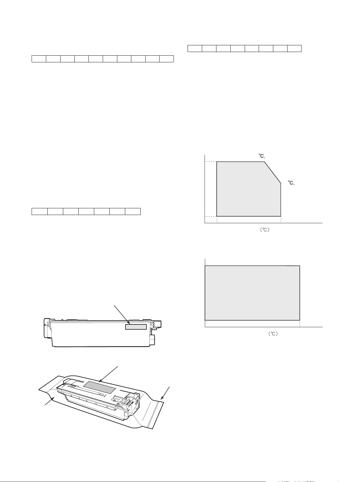
B. Toner cartridge
The lot number is of 7 digits, and each digit indicates as follows.
The lot number shall be printed in the position shown in the figure.
12 34567
1 Version number (A - sequentially revised)
2 Numeral figure
Indicates the end digit of the production year.
3 Alphabet
Indicates the production factory. (B for SOCC)
4 Destination code
5/6 Numeral figures
Indicates the production day.
7 Numeral figure or X, Y, Z
Indicates the production month.
X stands for October, Y November, and Z December.
C. Developer cartridge
The lot number is of 8 digit, and each digit indicates as follows.
The lot number shall be printed on the bag.
12345678
1 Alphabet
Indicates the production factory.
2 Number
Indicates the production year.
3/4 Number
Indicates the production month.
5/6 Number
Indicates the production day.
7 Hyphen
8 Number
Indicates the production lot.
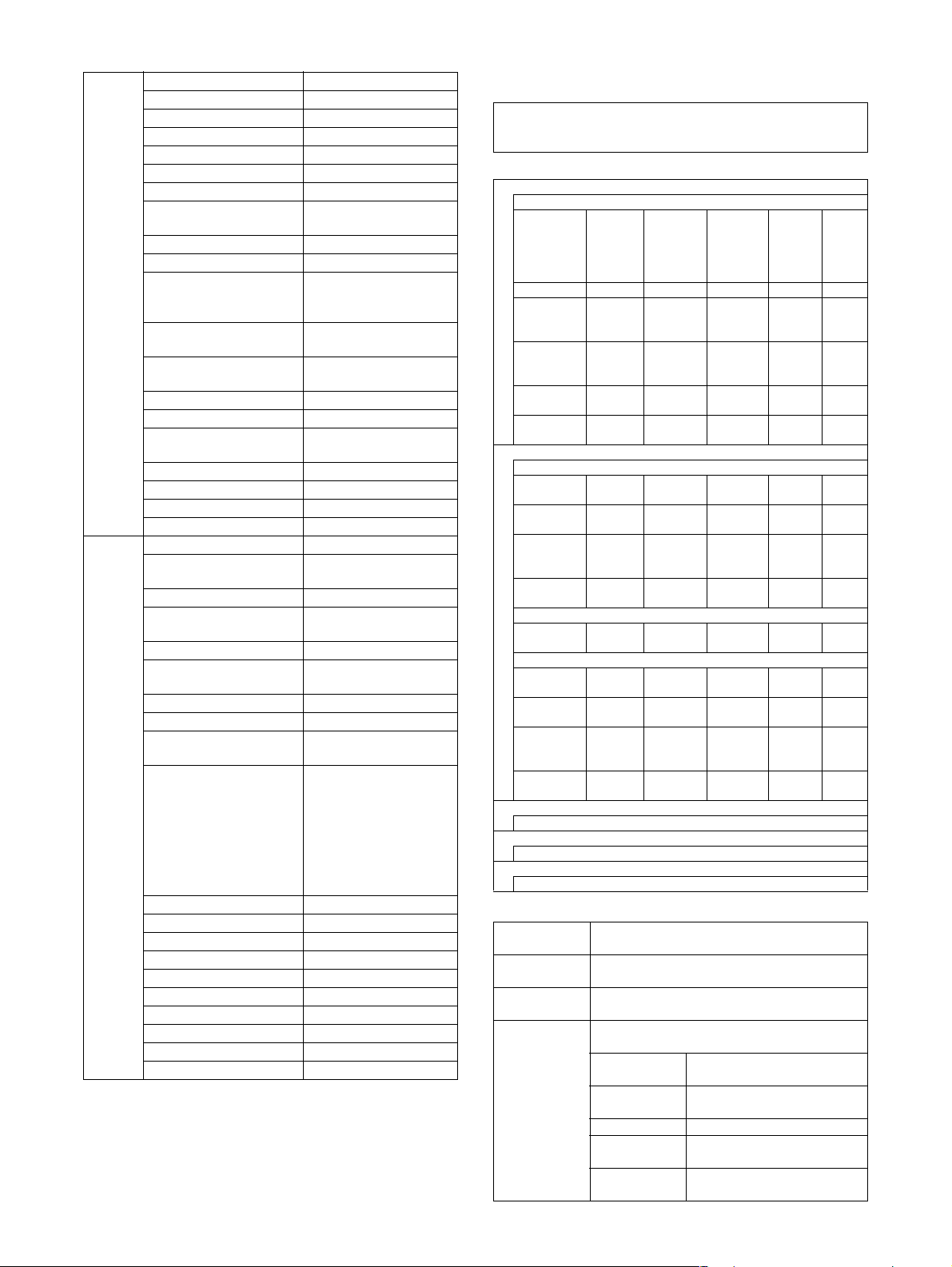
3. Environmental conditions
A. Operating conditions
85%
85
Humidity (%)
20
10 35
Temperature
B. Storage conditions
90
30
60%
35
(Without dew condensation)
Aluminum bag
Serial No. attachment
Serial No. attachment
MX-M350/M450 N/U CONSUMABLE PARTS 4 - 5
Heat seal
Humidity (%)
20
-10 40
Temperature
(Without dew condensation)
Page 24
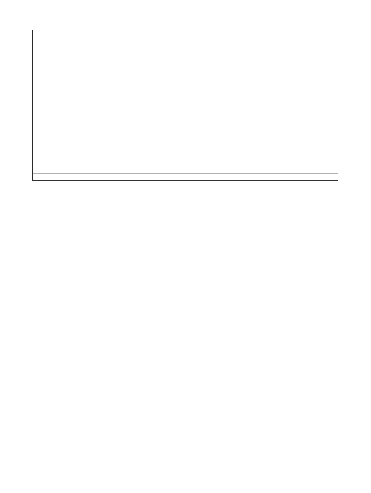
[5] EXTERNAL VIEWS AND INTERNAL STRUCTURES
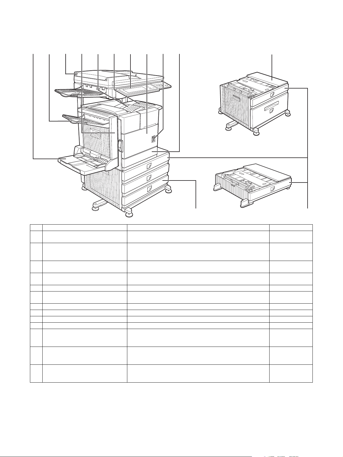
1. Exterior
12345678910
11
12
13
No. Name Function/Operation Note
1 Bypass tray This tray can also be used for special papers including transparency
film.
2 Exit tray The tray is extendable to support large size paper. Extend the tray
when 11" x 17", 8-1/2" x 14", 8-1/2" x 13", A3 or B4 paper is being
used.
3 Automatic document feeder This automatically feeds and scans multiple sheet originals. Both
4 Duplex module Module for two-sided printing Option
5 Upper paper output area (Center tray) Finished sheets are deposited here. –
6 Upper exit tray extension Provides support for large size paper. Option
7 Operation panel – –
8 Front cover Open to add toner. –
9 Power switch Press to turn power on and off. –
10 Paper tray 1 – –
11 Stand/3 x 500 sheet paper drawer This paper feed unit contains an upper multi-purpose drawer and
12 Stand/MPD & 2000 sheet paper drawer This paper feed unit contains an upper multi-purpose drawer and a
13 Multi purpose drawer Up to 500 sheets of 20 lbs. (80 g/m
sides of two-sided originals can be scanned at once.
two lower drawers each of which can hold a maximum of 500 sheets
of 20 lbs. (80 g/m
lower drawer which can hold a maximum of 2000 sheets of 20 lbs.
2
(80 g/m
special papers such as envelopes (standard sizes only) and
postcards can be set.
) paper.
2
) paper.
2
) paper can be loaded. Also
Option
(AR-DU4)
Option
(AR-DU4/AR-TE3)
Option
(MX-EFX1)
(AR-DU3/DU4)
(AR-TE4)
Option
(AR-D27)
Option
(AR-D28)
Option
(AR-MU2)
MX-M350/M450 N/U EXTERNAL VIEWS AND INTERNAL STRUCTURES 5 - 1
Page 25
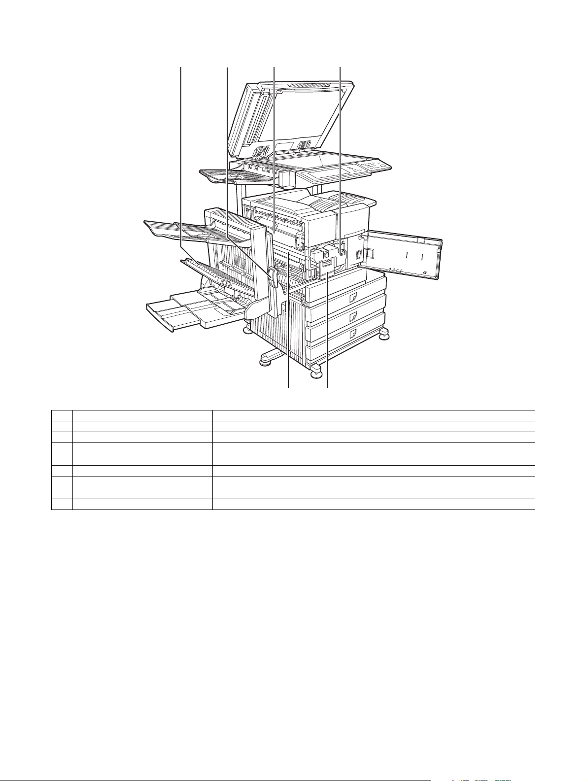
2. Interior
123 4
56
No. Name Function/Operation
1 Duplex module side cover Open when a misfeed has occurred in the duplex module.
2 Side cover latch Push up to open the side cover when a misfeed has occurred in the main unit.
3 Fusing unit Lift up to open the side cover when a misfeed has occurred in the main unit.
CAUTION: The fusing unit is hot. Take care in removing misfed paper.
4 Toner cartridge (drum/toner cartridge) The toner cartridge must be replaced when indicated on the operation panel.
5 Photoconductive drum Images are formed on the photoconductive drum.
NOTE: Do not touch or damage the photoconductive drum.
6 Cartridge lock lever When replacing the drum, toner or developer cartridge, turn down this lever and pull it out.
MX-M350/M450 N/U EXTERNAL VIEWS AND INTERNAL STRUCTURES 5 - 2
Page 26
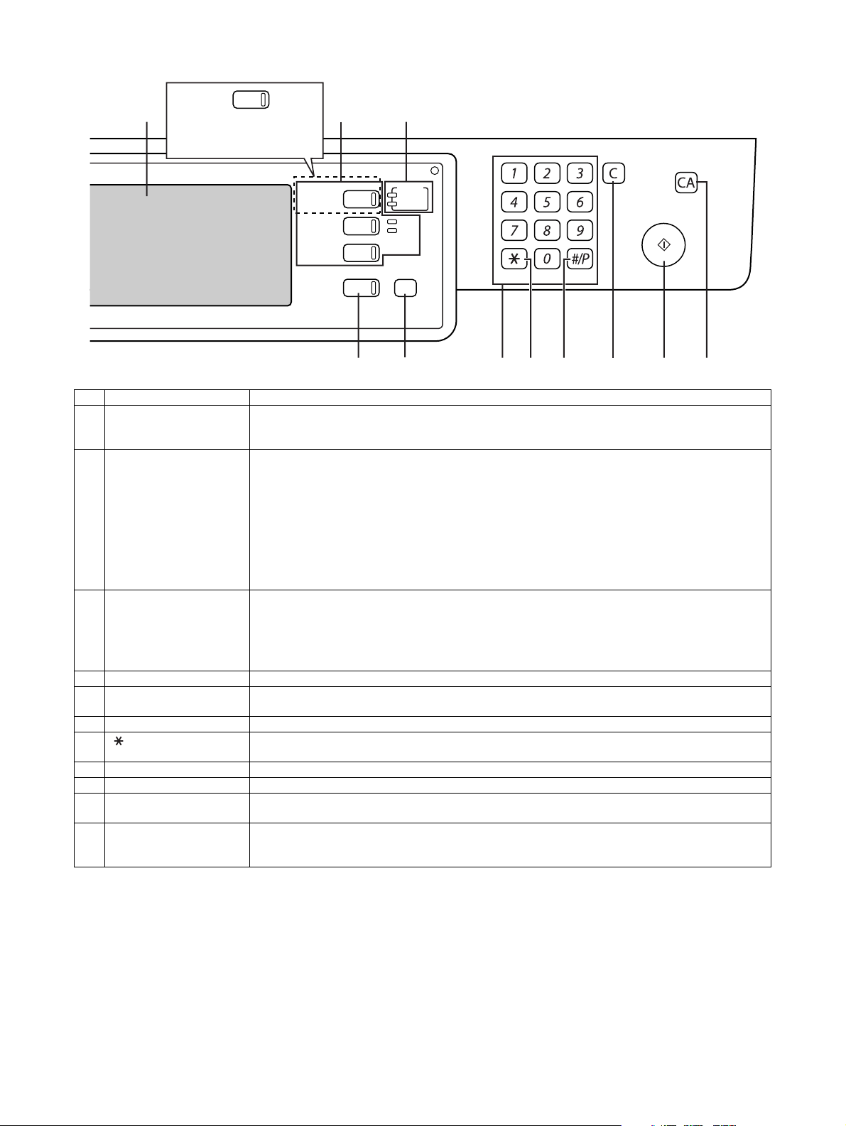
3. Operation panel
123
PRINT
When the document filing
function has not been
added.
PRINT
DOCUMENT
FILING
IMAGE SEND
COPY
JOB STATUS
READY
DATA
LINE
DATA
SYSTEM
SETTINGS
LOGOUT
4 5 6 7 8 9 10 11
No. Name Function/Operation
1 Touch panel The machine status, messages and touch keys are displayed on the panel. The document filing*
copy, network scanner*
desired function.
2 Mode select keys and
indicators
Use to change modes and the corresponding display on the touch panel.
[DOCUMENT FILING] key
Press to select the document filing mode*
∗ When the document filing function has not been added, this key is the [PRINT] key. This key is
pressed to change to the print mode screen.
[IMAGE SEND] key/LINE indicator/DATA indicator
Press to change the display to network scanner mode*
[COPY] key
Press to select the copy mode.
3 PRINT mode indicators READY indicator
Print data can be received when this indicator is lit.
DATA indicator
Lights up or blinks when print data is being received. Also lights up or blinks when printing is being
performed.
4 [JOB STATUS] key Press to display the current job status.
5 [SYSTEM SETTINGS] key This is used to store, edit, and delete user names and folder names for the document filing function*
and to configure the administrator settings and printer configuration settings.
6 Numeric keys Use to enter numeric values for various settings.
7 [ ] key ([LOGOUT] key) This key is used in copy mode, document filing mode*
Internet fax mode*
8 [#/P] key This is used as a program key when using the copy function, and to dial when using the fax function*
9 [C] key (Clear key) This key is used in copy mode, document filing mode*
10 [START] key Use this key to start copying in copy mode, scan a document in network scanner mode*
document for transmission in fax mode*
11 [CA] key (Clear all key) This key is used in copy mode, document filing mode*
Internet fax mode*
state.
*1: MX-M350N/M450N, or when the document filing function has been added.
*2: When the network scanner option is installed.
*3: When the fax option is installed.
*4: When the Internet fax option is installed.
2
, fax*3, and Internet fax*4 functions are used by switching to the screen for the
1
.
2
, fax mode*3 or Internet fax mode*4.
1
4
.
3
or Internet fax mode*4.
4
. Use the key to cancel settings and perform an operation from the initial machine
, network scanner mode*2, fax mode*3, and
1
, network scanner mode*2, and fax mode*3.
1
, network scanner mode*2, fax mode*3, and
2
, or scan a
1
,
1
,
3
.
MX-M350/M450 N/U EXTERNAL VIEWS AND INTERNAL STRUCTURES 5 - 3
Page 27
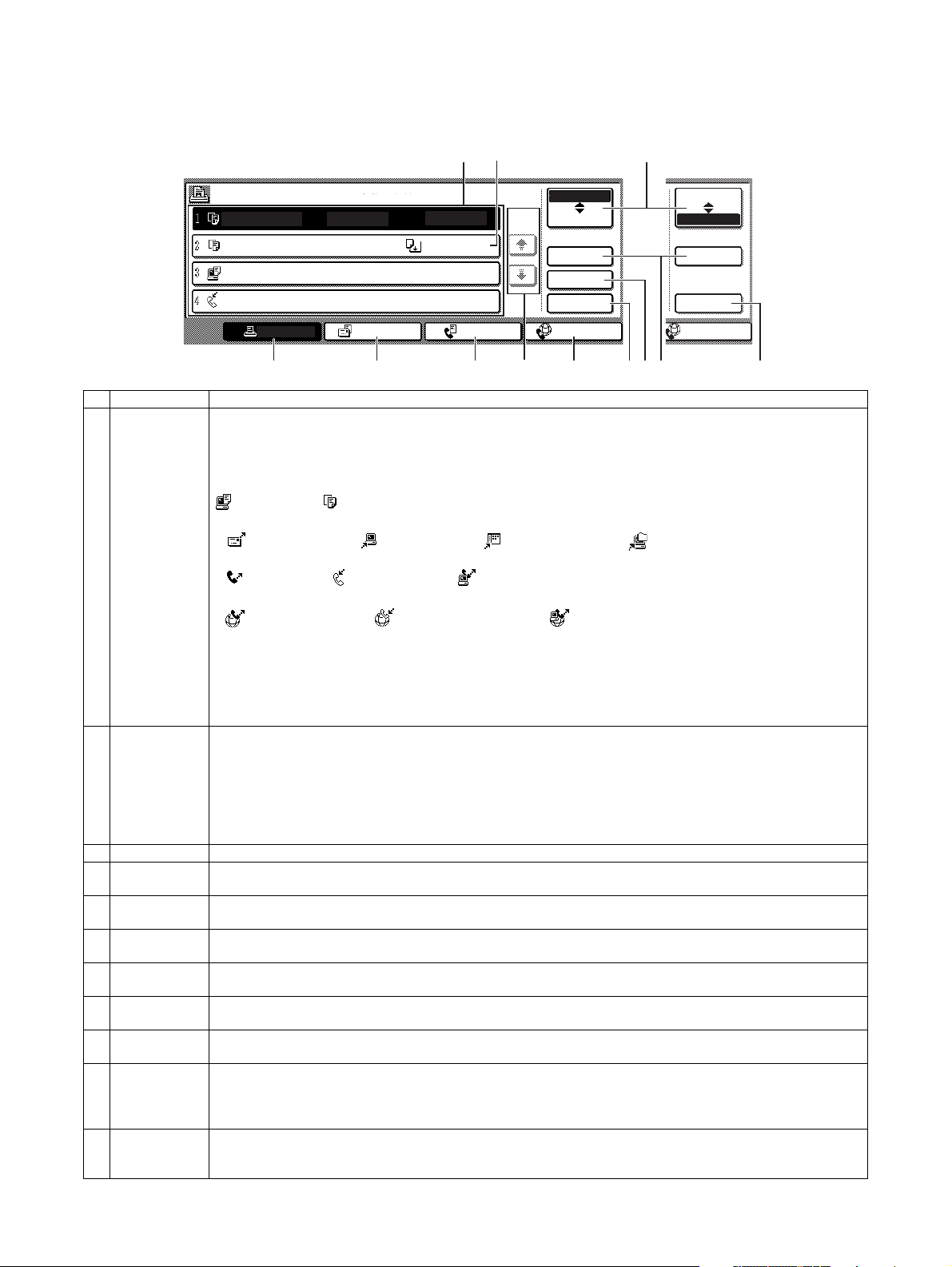
4. Job status screen (common to print, scan, fax and Internet fax)
This screen is displayed when the [JOB STATUS] key on the operation panel is pressed.
This screen can be used to display the "JOB QUEUE" (showing stored jobs and the current job) or the "COMPLETE" job list (showing fin-
ished jobs). This screen can be used to check jobs, interrupt a job in progress to perform another job, and cancel a job.
1
"JOB QUEUE" screen
JOB QUEUE
COPY
COPY
Suzuki
066211221
PRINT JOB
SETS / PROGRESS
020 / 001
020 / 000
020 / 000
002 / 000
SCAN TO
STATUS
COPYING
PAPER EMPTY
WAITING
WAITING
*1
FAX JOB
1/1
JOB QUEUE
COMPLETE
DETAIL
PRIORITY
STOP/DELETE
INTERNET-FAX
34567891011
No. Name Function/Operation
1 Job list The displayed jobs in the job list are themselves operation keys. To cancel printing or to give a job the highest print priority,
2 Mode select key This switches the job list display between "JOB QUEUE" and "COMPLETE".
3 [PRINT JOB] key This displays the print job list of print mode (copying, printing, fax reception, Internet fax reception, and self printing).
4 [SCAN TO] key This displays the transmission status and finished jobs of scan mode (Scan to e-mail, Scan to FTP, Scan to Desktop, and
5 [FAX JOB] key This displays the transmission/reception status and finished jobs of fax mode (fax and PC-Fax) when the fax option is
6 Display switching
keys
7 [INTERNET-FAX]
key
8 [STOP/DELETE]
key
9 [PRIORITY] key Touch this key after selecting a stored job in this [JOB QUEUE] list to print the job ahead of the other jobs.
10 [DETAIL] key This shows detailed information on the selected job. Files saved using the "FILE"*
11 [CALL] key*
*2: Can only be used on the MX-M350N/M450N, or when the document filing function has been added.
touch the relevant job key to select the job and execute the desired operation using the keys described in 8 and 9.
This shows the current job and the jobs waiting to be run. The icons to the left of the jobs in the queue show the job mode.
The document filing reprint job icon is highlighted.
Note that the icon does not become highlighted during retransmission of a fax/image transmission job.
Print mode Copy mode
SCAN mode
Scan to e-mail job Scan to FTP job Scan to Desktop job Scan to Network folder job
Fax mode
Fax send job Fax reception job PC-Fax send job
Internet Fax mode
Internet Fax send job Internet Fax reception job PC-Internet Fax send job
*1: "PAPER EMPTY" in the job status display
When a job status display indicates "PAPER EMPTY", the specified paper size for the job is not loaded in any of the trays.
In this case, the job will be suspended until the required paper is loaded. Other stored jobs will be printed (if possible) until
the required paper is loaded. (Other jobs will not be printed if the paper runs out during printing.) If you need to change the
paper size because the specified paper size is not available, touch the current job key to select it and then touch the
[DETAIL] key described in 10.
"JOB QUEUE": Shows stored jobs and the job in progress.
"COMPLETE": Shows finished jobs.
Files saved using the "FILE"*
the finished job screen. The "FILE"*
[CALL] key*
2
, to call up a finished job and print or transmit it. A finished broadcast transmission job key can be touched
2
and "QUICK FILE"*2 functions and finished broadcast transmission jobs appear as keys in
2
or "QUICK FILE"*2 job keys in the finished job screen can be touched, followed by the
followed by the [DETAIL] key to check the result of the transmission.
Scan to Network Folder) when the network scanner option is installed.
installed.
Use to switch the page of the displayed job list.
This displays the transmission/reception status and finished jobs of Internet fax mode and PC Internet fax mode when the
Internet fax option is installed.
Use to cancel or delete the current job or delete the stored job. Note that printing of received faxes and received Internet
faxes cannot be canceled or deleted.
Note that a job in progress cannot be interrupted if it is an interrupt copy job or if it is a list print job.
finished broadcast transmission jobs appear as keys in the finished job screen. A Quick File in the finished job screen or
2
the [Filing] key*
can be touched, followed by the [CALL] key*2, to call up a finished job and print or transmit it. A finished
broadcast transmission job key can be touched followed by the [DETAIL] key to check the result of the transmission.
2
When this key is touched after selecting a job in the COMPLETE job status screen (a job stored using the FILE or QUICK
FILE keys of the document filing function), the "JOB SETTINGS" menu screen appears to let you resend or reprint the
finished job.
2
"COMPLETE"
job screen
JOB QUEUE
COMPLETE
DETAIL
CALL
INTERNET-FAX
2
and "QUICK FILE"*2 functions and
MX-M350/M450 N/U EXTERNAL VIEWS AND INTERNAL STRUCTURES 5 - 4
Page 28
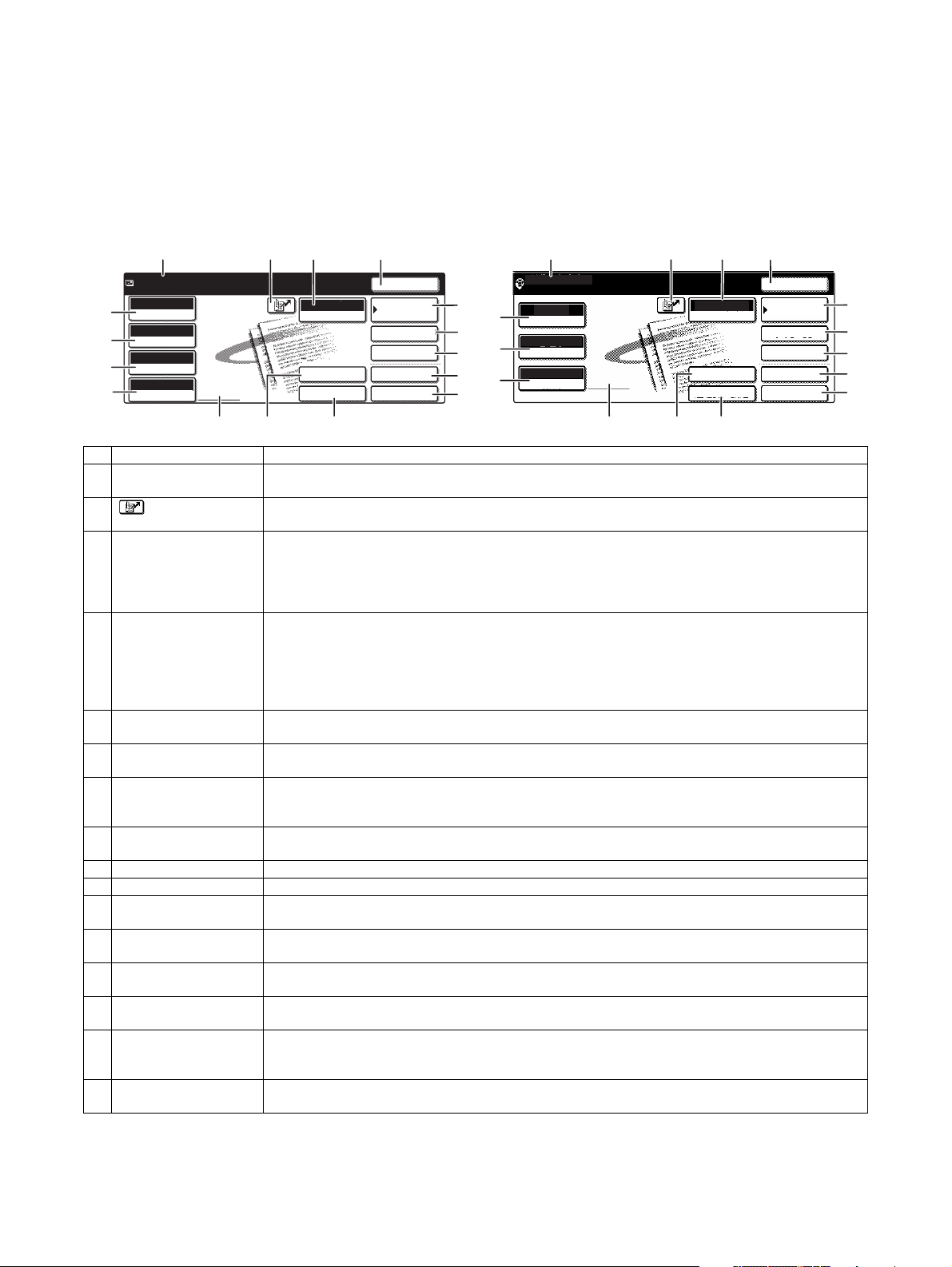
5. BASE SCREEN
ADDRESS BOOK
AUTO
READY TO SEND
.
ORIGINAL
300x300dpi
RESOLUTION
PDF MMR(G4)
FILE FORMAT
AUTO
SCAN
EXPOSURE
SPECIAL MODES
ADDRESS REVIEW
RESEND
FILE
ADDRESS ENTRY
MODE SWITCH
QUICK FILE
SEND SETTINGS
To display the base screen of a mode, touch the [IMAGE SEND] key in the touch panel and then select the desired mode with the [MODE
SWITCH] key.
If you have set the display to show the address book screen when the [IMAGE SEND] key is pressed, touch the [CONDITION SETTINGS]
key in the address book to display the condition setting screen.
The administrator setting can be used to set the display to show either the condition setting screen or the Address book screen when the
[IMAGE SEND] key is pressed.
A. Condition settings screen
Base screen of scan mode Base screen of Internet fax mode
16
15
14
13
1234
5
6
7
8
9
16
15
13
1234
READY TO SEND
EXPOSURE
STANDARD
RESOLUTION
ORIGINAL
AUTO
AUTO
.
INTERNET-FAX
MODE SWITCH
ADDRESS ENTRY
SEND SETTINGS
RESEND
ADDRESS BOOK
ADDRESS REVIEW
SPECIAL MODES
FILE
QUICK FILE
5
6
7
8
9
11
12
No. Name Function/Operation
1 Message display Messages appear here to indicate the current status of the machine.
2 [ ] (Quick) key When you add a one-touch key or a group key, the machine will automatically assign a shortened number.
3 [MODE SWITCH] key Touch this to change the image send mode.
4 [RESEND] key Touch this key to resend to the last Scan to E-mail, Internet fax, or fax destination used.
5 [ADDRESS BOOK] key This displays the Address Book screen. Touch this key when you wish to use a onetouch key that has a
6 [ADDRESS REVIEW] key When performing a broadcast transmission, touch this key to check your selected destinations. Your
7 [SPECIAL MODES] key Touch this key to set the special modes.
8 [FILE] key Touch this key to store a document image that you are transmitting in the hard disk (this includes selecting
9 [QUICK FILE] key Touch this key to store a document image that you are transmitting in the temporary storage folder.
10 [SEND SETTINGS] key Touch this key to set the subject, file name, and sender name.
11 [ADDRESS ENTRY] key When performing Scan to E-mail, touch this key if you wish to enter the e-mail address of the recipient
12 Two-sided scanning icon
display
13 [ORIGINAL] key Touch this key when you wish to manually set the size of the original to be scanned or scan both sides of
14 [FILE FORMAT] key Touch this key to set the file format of scan images that you transmit. The selected file format setting will be
15 [RESOLUTION] key Touch this key to change the resolution setting for the original to be scanned. The selected resolution
16 [EXPOSURE] key Touch this key to change the exposure setting for the original to be scanned. The selected exposure setting
When the machine is ready to send, an icon appears to the left.
Use this key for a three-digit shortened number to simplify the transmission procedure.
The modes that can be selected will vary depending on the peripheral devices (network scanner expansion
kit, facsimile expansion kit, Internet fax expansion kit) that are installed.
When the application integration module is installed, the [DATA ENTRY] key appears below the [MODE
SWITCH] key.
Note that the following types of destinations are not retained for the resend function.
• A one-touch key in which multiple destinations are stored (group key).
• Scan to FTP, Scan to Desktop, and Scan to Network Folder addresses.
• Broadcasting addresses • Addresses used only for BCC delivery
After the resend address is entered, the key changes to the [NEXT ADDRESS] key.
destination (or group) programmed in it.
selected destinations will appear as a list, and the list can be edited.
• Program • Erase • Dual page scan • Timer • 2 in 1 • Card shot
• Job build • Transaction report
a user name, file name, and location).
manually instead of using a one-touch key.
Icons appear here when you touch the [ORIGINAL] key and select two-sided scanning. The icons can be
touched to open function selection screens.
the original.
highlighted above the key. The initial factory setting is "PDF MMR(G4)".
setting will be highlighted above the key. The initial factory setting is "300x300dpi" (SCAN mode) or
"STANDARD" (INTERNET-FAX mode).
will be highlighted above the key. The initial factory setting is "AUTO".
10
12
11
10
MX-M350/M450 N/U EXTERNAL VIEWS AND INTERNAL STRUCTURES 5 - 5
Page 29
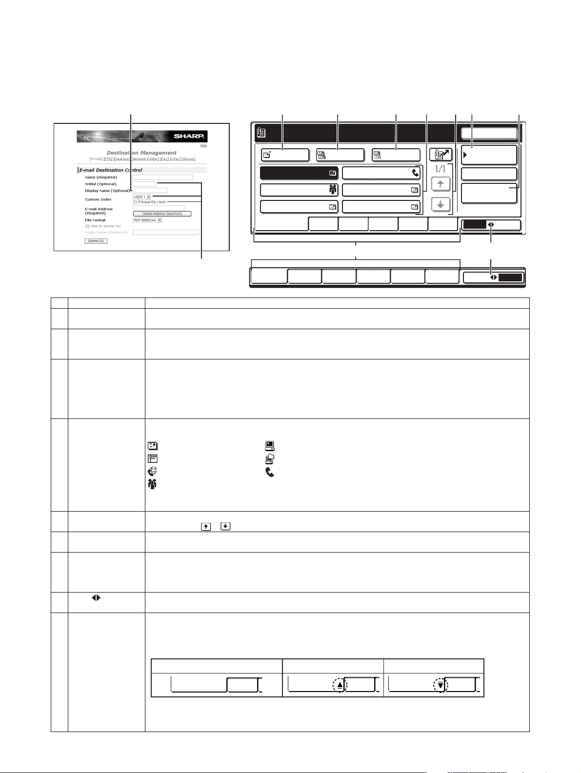
B. Address book screen
USER 1 USER 2 USER 3 USER 4
USER 5
USER 6
GROUP
ABC
ABC GROUP
TO
FREQUENT USE ABCD EFGHI JKLMN OPQRST UVWXYZ
CC
BCC
TEST5 TEST6
TEST3
TEST1 TEST2
GLOBAL
ADDRESS SEARCH
CONDITION
SETTINGS
READY TO SEND.
ADDRESS REVIEW
RESEND
If you have set the initial screen to the address book screen using the Administrator setting, the initial screen will appear as follows.
Destinations stored using the Web page are grouped in indexes (9) according to the letter entered in "Initial" for each destination, and the
name entered in "Display Name" is displayed in the one-touch key (4).
The screen shown below is the address book screen with an alphabetical index. The address book screen can be set with the group index
as the initial screen.
12 34 7564
TEST4
98
9
E-mail Destination Management page
No. Name Function/Operation
1 [TO] key After selecting a destination using a one-touch key or the global address search function, touch this key. For
2 [CC] key If you wish to a send "CC" ("Carbon Copy") of a Scan to E-mail transmission to other recipients in addition to
3 [BCC] key This key only appears when the [ENABLE BCC] checkbox is selected in [BCC SETTING] in the administrator
4 One-touch key
display
5 Display switching
keys
6 [CONDITION
SETTINGS] key
7 [GLOBAL AD DRESS
SEARCH] key
8 [ABC GROUP]
key
9 Index keys One-touch key destinations are stored on each of these index cards (alphabetical index or group index). Touch
Scan to E-mail or Internet-Fax transmission, you can select multiple destinations before touching this key.
the main recipient, after selecting destinations using one-touch keys or the global address search function,
touch this key. You can select multiple destinations before touching this key.
settings.
If you wish to send a "BCC" ("Blind Carbon Copy") of a Scan to E-mail transmission to other recipients in
addition to the main recipient, after selecting destinations using one-touch keys or the global address search
function, touch this key. Other recipients will not be informed that a copy was sent to the "BCC" recipients. You
can select multiple destinations before touching this key.
This shows the one-touch keys that have been stored on the selected "index card". The key type is indicated by
the icon at the right.
: Scan to E-mail : Scan to FTP
: Scan to Desktop : Scan to Network Folder
: Internet-Fax : Fax (An optional facsimile expansion kit is required.)
: Multiple destinations including Scan to E-mail and Fax destinations
This can be changed to 6 or 9 using the administrator setting, "The number of direct address/sender keys
displayed setting".
In cases where the one-touch keys cannot all be displayed on one screen, this shows how many screens are
left. Touch the " " " " keys to move through the screens.
This displays the Condition settings screen, which is used to set various conditions.
This feature makes it possible to search for an email address in an Internet or intranet directory database.
To use this function, the IP address (or network name) of the LDAP server must be set, as well as an account
name and password. These settings are configured by accessing the Web server in the machine from a
computer. Click "LDAP" in the Web page menu frame to display the LDAP Setup screen.
Touch this key to switch between the alphabetical index and the group index.
an index key to display the card. Each time you touch the same index key, the order of display of one-touch
keys changes as follows: Order of registration → Alphabetical order → Reverse alphabetical order. An icon
indicating the current display order will appear on the tab.
Storing order (initially selected) Ascending order Descending order
FREQUENT USE ABCD
Group indexes make it possible to store one-touch keys by group with an assigned name for easy reference.
This is done with the custom settings. Frequently used one-touch key destinations can be stored on the
FREQUENT USE card for convenient access.
MX-M350/M450 N/U EXTERNAL VIEWS AND INTERNAL STRUCTURES 5 - 6
FREQUENT USE ABCD FREQUENT USE ABCD
Page 30
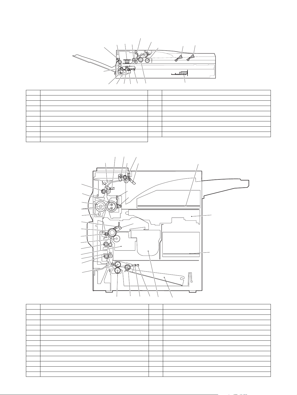
6. Cross sectional view
A. Scanner unit
17 SPOD
15
16
3 SPPD
1
2
4 SPED
7
5
6
14
1213
11
910
8
No. Name No. Name
1 CIS unit 10 Copy lamp base unit
2 Original resist roller 11 No. 1 mirror
3 Original resist front sensor (SPPD) 12 Copy lamp (Xenon)
4 Original set sensor (SPED) 13 Mirror base unit
5 Original take-up sensor 14 No. 3 mirror
6 Original length sensor 1 (SPLS1) 15 No. 2 mirror
7 Original length sensor 2 (SPLS2) 16 Original exit roller
8 CCD/lens unit 17 Original exit sensor
9 Original feed roller
B. Engine
POD1 POD2 POD3
PPD1
17
26
10
20
15
16
22 2321
18
19
3
1
8
6
9
5
2
24
4
25
11
13 PED TUD
12
14
7
No. Name No. Name
1 OPC drum 14 Machine tray (Paper tray1) rotating plate
2 Main charger 15 Upper heat roller
3 Cleaning blade 16 Pressure roller
4 LSU 17 Heater lamp
5 Developing unit 18 Thermistor (RTH1 / RTH2)
6 Magnet roller 19 Thermostat
7 Toner hopper 20 Fusing back roller
8 Transfer roller 21 Reverse gate
9 Resist roller 22 Paper exit roller
10 Paper transport roller 23 Full detection lever
11 Machine tray (Paper tray1) paper feed roller 24 Printer control PWB
12 Machine tray (Paper tray1) separation roller 25 Power supply unit
13 Machine tray (Paper tray1) take-up roller 26 Cleaning roller
MX-M350/M450 N/U EXTERNAL VIEWS AND INTERNAL STRUCTURES 5 - 7
Page 31

7. Switch, Sensor
A. Scanner unit
12
5
4
3
2
1
6
7
8
11
10
Code Name Active condition
1 SPPD SPF original resist front sensor
2 SCOV SPF paper feed cover sensor
3 SPED SPF original set sensor
4 OCSW OC open/close sensor
5 ORS-LED Original size sensor PWB (Light emitting side)
6 SPLS1 SPF original length sensor 1
7 SPLS2 SPF original length sensor
8 SPFVR SPF original width detection volume PWB
9 ORS-PD Original size sensor PWB (Light receiving side)
10 SOCD SPF open/close sensor
11 SPOD SPF original exit sensor
12 MHPS Mirror home position sensor
B. Engine
5.POD3
4.POD2
2.DSW-L
3.POD1
9
7.TCS
8.LUD
6.PPD1
1.DSW-F
9.PED
10.MAIN SW
Code Function/Operation Active condition
1 DSW-F Front door open/close detection H= Door open
2 DSW-L Left door open/close detection H=Door open
3 POD1 Paper exit detection L= Paper detection
4 POD2 Paper exit detection L= Paper detection
5 POD3 Paper exit detection Full L= Paper detection
6 PPD1 Paper transport detection L= Paper detection
7 TCS Toner concentration sensor
8 LUD Paper feed cassette upper limit detection H= Upper limit detection
9 PED Paper feed cassette paper empty detection L= Paper empty detection
10 MAIN SW Power switch
MX-M350/M450 N/U EXTERNAL VIEWS AND INTERNAL STRUCTURES 5 - 8
Page 32

8. PWB
A. Scanner unit
2
1
6
3
13
4
5
12
11
10
9
8
14
7
No. Name Function/Operation
1 SPF control PWB SPF control
2 Original size detection PWB (Light emitting side) Original size detection when using the table glass
3 CCD PWB (in lens unit) (The lens unit cannot be disassembled.) Image scan (Table glass/SPF surface)
4 SPF original width detection volume PWB SPF original width detection
5 MFP operation PWB Panel operation control
6 Scanner control PWB Scanner unit control
7 LVDS PWB LCD signal relay
8 Original size sensor (Light receiving side) Original size detection when using the table glass
9 CIS unit (in CIS unit) (The CIS unit cannot be disassembled.) Image scan (SPF back surface)
10 CIS interface PWB (in CIS unit) (The CIS unit cannot be disassembled.) CIS signal AD conversion process
11 Scanner interface PWB Scanner unit and connection of scanner control PWB
12 CIS control PWB CIS unit control and image process
13 CL inverter PWB Inverter for copy lamp
14 LCD INV PWB Generates a high voltage for the backlight.
B. Engine
1
2
7
4
5
11
8
6
10
13
9
12
3
No. Name Function/Operation
1 PRT controller Image process, image data communication control
2 PCU PWB Overall control of the machine and options
3 Power supply unit DC power supply
4 LD PWB (Inside LSU) Laser ON control (Inside LSU: LSU cannot be disassembled.)
5 Mother PWB Signal interface between PCU and the controller
6 Reactor PWB (200V only) / Filter PWB (Taiwan only) Noise filter
7 BD PWB Laser control (Inside LSU: LSU cannot be disassembled.)
8 High voltage resistor PWB High voltage load adjustment
9 Cassette detection PWB Paper cassette control
10 Drawer PWB Fan control
11 High voltage PWB High voltage power supply
12 Fuse PWB Protection of the machine when an abnormal power is supplied.
13 Relay PWB HDD back up
MX-M350/M450 N/U EXTERNAL VIEWS AND INTERNAL STRUCTURES 5 - 9
Page 33

9. Motor, Clutch, Solenoid
A. Scanner unit
5
4
3
1
2
7
6
No. Name Function/Operation
1 SPFM SPF motor Original transport in SPF scan
2 SRRC SPF original resist clutch SPF original scan timing adjustment
3 SPFC SPF original feed clutch SPF original feed roller drive
4 SDSS SPF original stopper solenoid SPF original stopper gate drive
5 MIRM Mirror motor Mirror base copy lamp base drive
6 SPFS SPF original feed solenoid SPF original feed unit drive
7 STMPS Stamp solenoid Finish stamp drive (Japan only)
B. Engine
10.CFM2
3.POM
13.PSPS 16.CNTFAN
6.VFM2
17.PM
1.DM
15.HDDFAN
14.RRC
12.TRC
2.MM
11.CPFC
5.LUM
8.CFM1
4.TM
Code Function/Operation Type
1 DM Drum motor Brushless motor
2 MM Main motor Brushless motor
3 POM Paper exit motor Stepping motor
4 TM Toner motor Synchronous motor
5 LUM Lift-up motor Synchronous motor
6 VFM2 Heat exhaust fan motor Fan motor
7 VFM1 Cooling fan motor Fan motor
8 CFM1 Suction fan motor Fan motor
10 CFM2 Ozone exhaust fan motor Fan motor
11 CPFC Paper cassette paper feed clutch
12 TRC Paper transport clutch
13 PSPS Separation solenoid
14 RRC Resist roller clutch
15 HDDFAN Cooling fan motor (for HDD) Fan motor
16 CNTFAN Cooling fan motor (for controller) Fan motor
17 PM Polygon motor Polygon motor
7.VFM1
7.VFM1
MX-M350/M450 N/U EXTERNAL VIEWS AND INTERNAL STRUCTURES 5 - 10
Page 34

[6] UNPACKING AND INSTALLATION
1. Installing procedure flowchart
There are many combinations between this machine and option
units. For installing option units, observe the following procedures
for efficiency.
To install the devices effciently, follow the procedure below.
Some peripheral devices may have been installed as standard
devices depending on the main unit model.
Part of descriptions and illustrations may be different.
Scanner/document feeder device
Finishing device
Start of installation
Main unit, paper feeding
device, and power supply
unit.
AR-MU2
AR-D27
AR-D28
Main unit
Duplex/bypass
device installed?
No
Finishing device
installed?
No
Yes
Yes
Main unit
Install duplex/pypass device.
AR-DU3
AR-DU4
Install finishing device.
AR-MS1
AR-FN6
AR-FN7
AR-PN1A / B / C / D
Finishing device
Paper feeding deviceDuplex device
* To install the AR-MU2, the optional exclusive-use desk is required.
Install controller board,
facsimile unit or other electric
Controller board,
facsimile unit or other
electric devices
installed?
No
[Electrical setting/adjustment]
1) Installation of driver software, setting,
and operation check
Main unit/MX-EFX1/AR-FX12/MX-NBX2/MX-NBX3/
AR-PK6/MX-NSX1
2)
Paper guide position adjustment/off center adjustment
AR-MU2/AR-D27/AR-D28/
AR-DU3/AR-DU4
End
Yes
devices.
AR-FX12/AR-MM9
MX-NBX2
MX-NBX3
AR-PK6
MX-NSX1
Extended memory
Install scanner/document feeder.
MX-EFX1/AR-RK2
When installing a paper feeding device or a duplex/bypass device, be sure to reattach
the rear cabinet, the AC inlet cover, and the harness cover of the main unit at the end
of installation as needed.
When installing a controller board, a facsimile unit, and other electric devices, be sure to install them
at a time.
Only off center adjustment is needed for AR-DU3.
∗ For installation of an option unit, refer to the Service Manual of the option unit.
MX-M350/M450 N/U UNPACKING AND INSTALLATION 6 - 1
Page 35

2. Note for installation place
Improper installation may damage this product. Please note the
following during initial installation and whenever the machine is
moved.
1) The machine should be installed near an accessible power
outlet for easy connection.
2) Be sure to connect the power cord only to a power outlet that
meets the specified voltage and current requirements. Also
make certain the outlet is properly grounded.
• For the power supply requirements, see the name plate of
the main unit.
3) Do not install your machine in areas that are:
• damp, humid, or very dusty
• exposed to direct sunlight
• poorly ventilated
• subject to extreme temperature or humidity
changes, e.g., near an air conditioner or heater.
4) Be sure to allow the required space around the machine for
servicing and proper ventilation.
11-13/16" (30cm)
MX-M350N/M450N MX-M350U/M450U
CD-ROM (Printer)
Maintenance card/Maintenance case (Except UK)
Warranty Registration (UK only)
Delivery/installation report (Europe only)
MSDS card (North America/UK only)
Warranty (Australia only)
Scanner key sheet (Local area only)
Dust cover (Local area only)
3) Remove the cushioning materials from the right and left of the
front side.
31-1/2"
(80cm)
23-5/8"
(60cm)
23-5/8" (60cm)
3. Unpacking procedure
1) Release the joint, and remove the packing case.
2) Remove the top pad, and open the electrostatic polyethylene
bag.
4) Remove the locking tape from the right and left sides of the
tray.
Then, Remove the top of the carton and lower the plastic bag
covering the machine while the machine is still on the carton
base.
5) Remove the packing tape from the paper tray, pull out the
paper tray until it stops and remove it by tilting it upward.
6) One person must lift by the empty front tray pocket with the
right hand and steady the machine with the left hand placed at
the upper left of the machine.
The other person must lift with the right hand by using the lifting recess in the rear of the machine and also steady the
machine with the left hand as shown in the illustration.
Front side
Check the following items are included in the package.
MX-M350N/M450N MX-M350U/M450U
Operating Manual
(Common/Copier, Administrator guide (System settings))
Web manuals (Printer)
(Network Scan)
Installation manual (PCL/PS)
MX-M350/M450 N/U UNPACKING AND INSTALLATION 6 - 2
–
Rear side
Note: The center of gravity of the machine lies in the left side
when viewed from the Back of machine. When lifting the
machine, be careful not to drop it.
Page 36

4. Unpacking and installation of the desk unit
Note: In advance to installation of the machine, the paper feed
option units (AR-D27/AR-D28/AR-MU2) should have been
installed.
A. AR-D28
<Before installation>
• Start installation after checking that the DATA and COMMUNI-
CATION indicators on the operation panel are neither lit nor
blinking.
Caution: The lower tray cannot be pulled out unless the adjuster
is lowered to the specified position.
3) Put the main unit of the printer on the stand/paper drawer.
<1> Pull out the paper tray of the main unit until it stops and then
remove it by lifting both ends of the tray.
<2> Hold the main unit of the printer at the positions shown in the
illustration and put the main unit on the stand/paper drawer
so that the front side and the left side of the main unit are
aligned to those of the stand/paper drawer.
Front side
Rear side
<Parts included>
Left adjuster: 1 pc.
Front mounting
plates: 2 pcs.
Left paper guides: 2 pcs. Right paper guides: 2 pcs.
Rear mounting
plates: 2 pcs.
Screws (M4x6):
4 pcs.
1) Turn off the main switch of the main unit of the printer.
Turn the main switch located on the front side of the printer to
the "OFF" position.
Then remove the power plug from the outlet.
"OFF"
2) Attach the adjusters and adjust them.
<1> Insert the left adjusters to the stand/paper drawer.
<2> Turn the each adjusters to lower them until they touch the
floor.
Caution: For installation of the main unit, it must be held by two
persons and installed without haste.
4) Connect the main unit to the stand/paper drawer.
<1> Attach the rear mounting plates using a supplied screw for
each.
Rear mounting plate
Screw
Rear mounting plate
Rear
mounting plate
Desk frame
Screw
Caution: Insert the rear mounting plates under the desk frame.
2
2
2
1
∗ Be sure to attach the left adjuster to prevent overturning.
2
MX-M350/M450 N/U UNPACKING AND INSTALLATION 6 - 3
Page 37

<2> Pull out the upper paper tray of the stand/paper drawer until it
r
stops and attach the front mounting plates using a supplied
screw for each.
Then, remove the lock of the paper tray and close the tray.
Front
mounting plate
Screw
Remove the M4 screw shown in the illustration, insert the circle terminal of ground harness, and it fixes again.
Front mounting
plate
Screw
<3> Reattach the paper tray of the main unit.
5) Connect the power supply I/F harness to the PCU PWB of the
main unit of the printer.
<1> Remove the screw that fixes the harness cover of the main
unit of the printer and slide the harness cover up to remove it.
Process the harness cover as shown in the illustration.
Screw
Cut out.
Harness cover
<2> Connect the power supply I/F harness connector (red, 22pin)
to CN11 (red connector) of the PCU PWB of the main unit of
the printer.
<3> Reattach the power supply I/F harness cover to its original
position and fix it with the removed screw.
At this time, ensure that the power supply I/F harness are
arranged as shown in the illustration.
• Fix the harness securely to the wire saddle.
Screw
Power supply
I/F harness
Harness cove
Wire saddle
Wire saddle
6) Attach the paper guides to the lower tray (large capacity tray)
and set the size.
Refer to "Setting and adjustment" described later.
∗ If another peripheral device must be installed, carry out the fol-
lowing step at the end of the installation work.
7) Adjust the position of the paper guides of the upper paper tray
of the stand/paper drawer.
Refer to "Setting and adjustment" described later.
8) Carry out the off center adjustment.
Connector
CN11
Connect the connector (white, 4pin) of power supply I/F harness to the I/F connector (white, 4pin) of the main unit.
MX-M350/M450 N/U UNPACKING AND INSTALLATION 6 - 4
Page 38

B. AR-D27
<Before installation>
• Start installation after checking that the DATA and COMMUNICATION indicators on the operation panel are neither lit nor
blinking.
<2> Hold the main unit of the printer at the positions shown in the
illustration and put the main unit on the stand/paper drawer
so that the front side and the left side of the main unit are
aligned to those of the stand/paper drawer.
Front side
Rear side
<Parts included>
Screws (M4x6):
4 pcs.
Left adjuster: 1 pc.
Front mounting
plates: 2 pcs.
Rear mounting
plates: 2 pcs.
1) Turn off the main switch of the main unit of the printer.
Turn the main switch located on the front side of the printer to
the "OFF" position.
Then remove the power plug from the outlet.
"OFF"
2) Attach the adjusters and adjust them.
<1> Insert the left adjusters to the stand/paper drawer.
<2> Turn the five adjusters to lower them until they touch the floor.
2
2
2
Caution: For installation of the main unit, it must be held by two
persons and installed without haste.
4) Connect the main unit to the stand/paper drawer.
<1> Attach the rear mounting plates using a supplied screw for
each.
Rear mounting plate
Screw
Rear mounting plate
Mounting plate
Desk frame
Screw
Caution: Insert the rear mounting plates under the desk frame.
<2> Pull out the upper paper tray of the stand/paper drawer until it
stops and attach the front mounting plates using a supplied
screw for each.
Then, remove the lock of the paper tray and close the tray.
Remove the locks of the middle tray and the lower tray similarly.
1
∗ Be sure to attach the left adjuster to prevent overturning.
2
Caution: The lower tray cannot be pulled out unless the adjuster
is lowered to the specified position.
3) Put the main unit of the printer on the stand/paper drawer.
<1> Pull out the paper tray of the main unit until it stops and then
remove it by lifting both ends of the tray.
MX-M350/M450 N/U UNPACKING AND INSTALLATION 6 - 5
Front mounting
plate
Front
mounting plate
Screw
Screw
Page 39

<3> Reattach the paper tray of the main unit.
5) Connect the power supply I/F harness to the PCU PWB of the
main unit of the printer.
<1> Remove the screw that fixes the harness cover of the main
unit of the printer and slide the harness cover up to remove it.
Process the harness cover as shown in the illustration.
<3> Reattach the harness cover to its original position and fix it
with the removed screw.
At this time, ensure that the power supply I/F harness is
arranged as shown in the illustration.
• Fix the harness securely to the wire saddle.
Screw
Power supply
I/F harness
Harness cover
Screw
Cut out.
Harness cover
<2> Connect the power supply I/F harness connector (red, 22pin)
to CN11 (red connector) of the PCU PWB of the main unit of
the printer.
Connector
CN11
Connect the connector (white, 4pin) of power supply I/F harness to the I/F connector (white, 4pin) of the main unit.
Remove the M4 screw shown in the illustration, insert the circle terminal of ground harness, and it fixes again.
Wire saddle
Wire saddle
6) Adjust the position of the paper guides of the upper paper tray
of the stand/paper drawer.
Refer to "Setting and adjustment" described later.
7) Carry out the off center adjustment.
C. AR-MU2
<Parts included>
Front mounting plates:
2 pcs.
Rear mounting plates:
2 pcs.
Screws (M4x8):
4 pcs.
1) Turn off the main switch of the main unit of the printer.
Turn the main switch located on the front side of the main unit
to the "OFF" position.
Then, remove the power plug of the main unit from the outlet.
MX-M350/M450 N/U UNPACKING AND INSTALLATION 6 - 6
"OFF"
Page 40

2) Put the main unit of the printer on the multi purpose drawer.
<1> Pull out the paper tray of the main unit until it stops and then
remove it by lifting both ends of the tray.
<2> Hold the main unit of the printer at the positions shown in the
illustration and put the main unit on the multi purpose drawer
so that the front side and the left side of the main unit are
aligned to those of the multi purpose drawer.
Front side
Rear side
<2> Pull out the paper tray of the multi purpose drawer until it
stops and attach the front mounting plates using a supplied
screw for each.
Then, remove the lock of the paper tray and close the tray.
Front
mounting plate
Screw
Front mounting plate
Screw
<3> Reattach the paper tray of the main unit of the printer.
Caution: For installation of the main unit, it must be held by two
persons and installed without haste.
3) Connect the main unit of the printer to the multi purpose
drawer.
<1> Attach the rear mounting plates using a supplied screw for
each.
Rear mounting plate
Screw
Rear mounting plate
Tray frame
Screw
Mounting
plate
Caution: Insert the mounting plate under the desk frame.
4) Remove the multi rear cabinet.
<1> Remove the two screws that secure the multi rear cabinet.
Screw
Multi rear cabinet
Screw
<2> Remove the two screws that secure the Harness protection
sheet.
MX-M350/M450 N/U UNPACKING AND INSTALLATION 6 - 7
Page 41

<3> Remove the filament tape that secure the the power supply I/
r
F harness.
5) Connect the harness to the main unit of the printer.
<1> Remove the screw that fixes the harness cover of the main
unit of the printer and then slide the harness cover up to
remove it.
Process the harness cover as shown in the illustration.
Screw
Cut out.
Harness cove
<3> Connect the connector (white, 4pin) of power supply I/F har-
ness to the I/F connector (white, 4pin) of the main unit.
Connect the power supply I/F harness connector (red, 22pin) to
CN11 (red connector) of the PCU PWB of the main unit of the
printer.
Remove the M4 screw shown in the illustration, insert the circle terminal of ground harness, and it fixes again.
Connector
CN11
∗ For installation of a finisher or a mail-bin stacker, see its installa-
tion manual.
6) Attach the harness cover.
Reattach the harness cover to its original position and fix it
with the removed screw.
At this time, ensure that the power supply I/F harness is
arranged as shown in the illustration.
• Fix the harness securely to the wire saddle.
Screw
<2> Connect the connector of the relay harness of the multi pur-
pose drawer to the connector of the PCU PWB of the main
unit of the printer.
CN10
Connector
Harness cover
Wire saddle
Wire saddle
∗ If another peripheral device must be installed, carry out the fol-
lowing step at the end of the installation work.
7) Adjust the position of the paper guides of the paper tray.
Refer to "Setting and adjustment" described later.
8) Carry out the off center adjustment.
MX-M350/M450 N/U UNPACKING AND INSTALLATION 6 - 8
Page 42

5. Unpacking and installation of the rack (AR-RK2)
1) Attach the rack to the desk unit.
★ Be sure to identify the left and the right racks. Refer to the fig-
ure below.
Insert the rack boss into the rack mounting hole (made by
removing the mold of the desk unit), and fix each rack with two
fixing screws (M5 x 70).
6. Machine installing procedure
A. Setting related to process
1) Open the left door and the front door, and remove the blue
screw in the developer cartridge section.
2) Remove the developer cartridge from the machine.
Rack sheet
Rack with the
rack sheet
attached to it
Fixing screws
(M5x70)
2) Attach the rack bottom plate.
Rack mounting hole
Boss
Boss
Rack mounting hole
Cam
Rack with the
cam attached
to it
3) Remove the top cover of the developer cartridge.
MX-M350/M450 N/U UNPACKING AND INSTALLATION 6 - 9
Page 43

4) While rotating the MG roller, supply developer into the developer cartridge evenly.
Note that the MG roller must be rotated in the arrow direction
as shown in the figure below.
Use of a metal scale or a screwdriver (-) facilitates the procedure.
Note: Before opening the developer seal, shake it 4 or 5 times.
5) Attach the top cover to the developer cartridge and install the
cartridge to the machine.
∗ After installing the machine, fix it with the blue screw.
3) Gently remove the sealing tape from the cartridge.
4) Return the cartridge lock lever.
B. Toner cartridge settings
1) Remove a new toner cartridge from the package and shake it
horizontally five or six times.
2) Insert a new toner cartridge.
Push the cartridge in until it locks securely into place.
C. Setting related to fusing
1) Put down the right and the left levers of the fusing unit in the
arrow direction.
D. Paper setting
1) Pull out the first stage paper feed tray.
Slowly pull out the tray until it stops.
MX-M350/M450 N/U UNPACKING AND INSTALLATION 6 - 10
Page 44

2) While pressing the paper holding plate, remove the fixing pin.
3) Put paper in the tray, and close the paper feed tray.
1) Turn off the main switch of the main unit of the printer.
Turn the main switch located on the front side of the printer to
the "OFF" position.
Then remove the power plug from the outlet.
"OFF"
2) Put the scanner unit on the rack.
Hold the handle of the scanner unit, and put the scanner unit
on the rack from the front side of the rack as shown in the figure. Slowly slide the scanner unit until it is brought into contact
with the rack and stopped.
7. Unpacking and installation of the MX-EFX1
Be sure to remove it,
or it may cause a trouble.
Rack
Scanner unit
3) Fix the scanner unit.
Fix the scanner unit which is on the rack with the fixing screw
(M4 x 8), and fix it to the rack with the M4 step screw (long,
short x 2).
M4 stepped
screw
Screw
(M4x8
M4 stepped
screw
Reference
Reference
4) Remove the fixing tape for scanner packing and remove the
fixing screw.
Remove the pack fixing tape and the fixing screws which are
fixing the scanner unit, and remove the packing note.
Parts included in the scanner unit
Operation manual
(1 pc.)
M4 step
screws (long)
(1 pc.)
Tray
(1 pc.)
M4 step
screws (short)
(2 pcs.)
Scanner unit
fixing screw
Scanner
rack sheel
(1 pc.)
Fixing screw
(M4x8)
(1 pc.)
MX-M350/M450 N/U UNPACKING AND INSTALLATION 6 - 11
Page 45

5) Connect the cable.
Connect the scanner unit connector with the printer connector,
and fix the connectors with two screws attached to the connector.
Scanner cable
Screws
Note: When inserting the connector, be careful not to break the
pins, and connect according to the guide.
6) Attach the paper exit tray.
Attach the paper exit tray to the scanner unit as shown in the
figure.
Paper exit tray
8. Automatic developer adjustment
1) Attach the cabinets which were removed.
2) Close the left door.
At that time, keep the front door open.
Note: The automatic developer adjustment must be performed by
entering the simulation mode with the front door open. If the
power is turned on with the front door closed, warm-up is
performed to supply toner to the developing unit. As a
result, the reference toner density cannot be obtained.
3) Insert the power plug into the power outlet.
4) Enter simulation 25-2.
5) Close the front door.
(LCD Display)
6) Press the [START] key, and the automatic developer adjustment will be performed.
During execution of the automatic developer adjustment,
“EXECUTING...” is displayed and the toner sensor value is
indicated on the LCD. (DEVE REFERENCE)
7) After about 2 min, the adjustment value is stored in the
machine. Check that the mode was normally completed.
Normal end: Returns to the initial window (PRESS
START display).
Abnormal end: Returns to the initial window (PRESS
START display), and indicates the trouble
display (TROUBLE! EE-**).
In case of an error end, remove the cause of the error, and
execute the automatic developer adjustment again.
8) Turn off/on the power, and the machine returns to the normal
mode and enters the warm-up mode.
9. Print test
1) After completion of warm-up (normal mode), select [SYSTEM
SETTINGS]
2) Print [ALL SETUP LIST] to check and confirm the print quality.
3) Press the [SYSTEM SETTINGS] key again to return to the
normal menu.
→ [Data list up] to display the menu.
10.Distortion adjustment
Note: This adjustment must be performed after installing the
machine and its peripheral devices.
There is basically no need because it has been made prior to shipping. If there should be a distortion as shown in the figure below,
perform the adjustment according to the following procedures.
1) Use a level gauge to check to confirm that the scanner unit is
installed horizontally.
Make a copy, and if any distortion is found as shown in Fig 1 or
Fig. 2, loosen the scanner fixing screw (M4 x 8) and the cam A
fixing screw (M3 x 12) to make an adjustment.
Fixing screw
(M4x8)
SIMULATION 25-2
AUTOMATIC DV ADJUSTMENT. PRESS START.
HUMIDITY AREA: 70.0 - 72.5
TEMPERATURE AREA: 70.0 - 72.5
DEVE REFERENCE: 128
Press [START] key. Press [SYSTEM SETTINGS] key, and the operation
is stopped immediately or after 2 min.
SIMULATION 25-2
AUTOMATIC DV ADJUSTMENT. EXECUTING···.
HUMIDITY AREA: 70.0 - 72.5
TEMPERATURE AREA: 70.0 - 72.5
DEVE REFERENCE: 118
MX-M350/M450 N/U UNPACKING AND INSTALLATION 6 - 12
[Fig. 1]
First copy image
Image
Paper
Difference
• Case of Fig. 1
Shift the cam A in the direction of A by the difference of the image.
For one scale (one groove), shift by 0.5mm.
After shifting the cam, tighten the cam A fixing screw (M3 x 12).
Make a copy again and check to confirm that there is no distortion
on the image.
Page 46

[Fig. 2]
First copy image
Image
Paper
Difference
• Case of Fig. 2
Shift the cam A in the direction of B by the difference of the image.
For one scale (one groove), shift by 0.5mm.
After shifting the cam, tighten the cam A fixing screw (M3 x 12).
Make a copy again and check to confirm that there is no distortion
on the image.
After adjustment, tighten the fixing screw (M3 x 12) and the scanner fixing screw (M4 x 8).
Attach the decoration seal to the screw hole.
(DSPF scan position automatic adjustment)
1) Execute SIM 53-8 after completion of the distortion adjustment.
2) If any distortion is made after execution of the simulation, execute the MB rail position adjustment. (Refer to "3-A OC scan
distortion adjustment (MB-B rail height adjustment)" in [8]
ADJUSTMENTS.)
13.Using the transport handle
1) Remove the screw, and remove the handle.
2) Insert the handle into the left rack notch diagonally upward as
shown in the figure.
3) Attach the screw which was removed in procedure 1) to
secure the handle.
11.Attach the document scanning label
Reference
6mm
Reference
15mm
12.Adjuster installation and adjustment
1) Insert the left adjuster into the paper feed desk.
2) Turn each adjuster until it is brought into contact with the floor.
2
2
2
4) Lift the rear edge of the handle to engage the head with
the rack.
5) After completion of transport, restore the handle to the original
position.
A
A
1
∗ Be sure to install the left adjuster in order to prevent falling down
of the machine.
Note: If the adjusters are not lowered to the specified positions,
the lower stage tray cannot be pulled out.
2
MX-M350/M450 N/U UNPACKING AND INSTALLATION 6 - 13
Page 47

[7] MAINTENANCE AND DETAILS OF EACH SECTION
• Self print of set values
Use of SIM 22-6 allows to print the set values and the jam his-
tory of the machine.
These values must be printed before execution of maintenance
or disassembly procedures.
• When assembling, check that the flat cable and the harness
connectors are securely connected.
• When connecting the flat cable, be careful not to break the pins.
When installing the PWB unit and the memory module, use a
Ground Strap to prevent damage caused by electrical discharge.
[Maintenance System Table]
1. Engine section
Maintenance cycle : 200K
✕ Check (Clean, replace, or adjust as necessary.) ❍ Clean ▲ Replace ∆ Adjust ✩ Lubricate ❏ Move position
Unit name Part name
Drum peripheral Drum ✕▲✕▲✕▲✕▲
Developing
section
Fusing section Upper heat roller ✕ ✕▲✕▲✕▲✕▲P/G No.: [7]-46
Filters Ozone filter ▲▲▲▲▲▲▲▲P/G No.: [12]-2
Paper feed
section
Transport section
Paper exit
reverse section
Drive section Gears (Specified position) ✕ ✩✩✩✩✩✩✩✩
Image quality ✕ ✕✕✕✕✕✕✕✕
Other Sensors ✕✕✕✕✕✕✕✕Clean with air.
Note 1: Replacement reference:Use the counter value of each paper feed port as the replacement reference.
Paper feed roller/Separation pad/Torque limiter section (Include Desk, Multi purpose): 100K or 1 year
Cleaner blade ✕▲✕▲✕▲✕▲Replace at 200K or 1 year.
Toner reception seal ✕▲✕▲✕▲✕▲P/G No.: [10]-42
Side molt F ✕▲✕▲✕▲✕▲P/G No.: [10]-33
Side molt R ✕▲✕▲✕▲✕▲P/G No.: [10]-37
Transfer roller ✕ ✕▲✕▲✕▲✕▲P/G No.: [5]-8
Discharge plate ✕ ✕▲✕▲✕▲✕▲P/G No.: [5]-2
TR bearing (F/R) ✕✕✕▲✕✕✕▲P/G No.: [5]-9, 18
Transfer roller collar ✕✕✕▲✕✕✕▲P/G No.: [5]-10
After-transfer star ring ✕✕✕✕✕✕✕✕P/G No.: [5]-19
TR gear ✕ ✕▲✕▲✕▲✕▲P/G No.: [5]-15
Drum separation pawl unit ✕▲✕▲✕▲✕▲P/G No.: [5]-501
MC unit ✕ ❍▲❍▲❍▲❍▲Includes the screen grid, the
Paper guide ❍ ❍❍❍❍❍❍❍❍
Developer ▲▲▲▲▲▲▲▲Supplied when installing
DV blade ✕▲✕▲✕▲✕▲P/G No.: [11]-55
DSD collar ❍❍❍❍❍❍❍❍
DV side seal F ✕▲✕▲✕▲✕▲P/G No.: [11]-38
DV side seal R ✕▲✕▲✕▲✕▲P/G No.: [11]-43
Toner cartridge ––––––––
Lower heat roller ✕ ✕▲✕▲✕▲✕▲P/G No.: [7]-22
Upper separation pawl ❍ ❍▲❍▲❍▲❍▲P/G No.: [7]-3
Lower separation pawl ❍ ❍▲❍▲❍▲❍▲P/G No.: [7]-41
Thermistor ✕ ✕✕✕✕✕✕✕✕Clean and remove paper dust.
Upper heat roller gear ✕▲✕▲✕▲✕▲P/G No.: [7]-47
Paper guides ❍ ❍❍❍❍❍❍❍❍
Gears ✩✩✩✩✩✩✩✩
CL roller ✕ ✕▲✕▲✕▲✕▲P/G No.: [7]-52
CL roller bearing ✕ ✕▲✕▲✕▲✕▲P/G No.: [7]-53
Pick-up roller ✕ ✕✕✕✕✕✕✕✕Note 1
Paper feed roller ✕ ✕✕✕✕✕✕✕✕Note 1
Separation roller ✕ ✕✕✕✕✕✕✕✕Note 1
Torque limiter ✕ ✕✕✕✕✕✕✕✕Note 1
Resist roller ✕ ❍❍❍❍❍❍❍❍
Transport rollers ✕ ❍❍❍❍❍❍❍❍
Transport paper guides ❍ ❍❍❍❍❍❍❍❍
Paper dust remover unit ❍ ❍▲❍▲❍▲❍▲P/G No.: [14]-51
Optical reflection sensor ❍ ❍❍❍❍❍❍❍❍PS roller unit section
Belts ✕ ✕✕✕✕✕✕✕✕
When
100K 200K 300K 400K 500K 600K 700K 800K Remark
calling
P/G No.: [10]-49
charging plate, and the MC
cleaner.
❍: Charging plate cleaning by
the MC cleaner
P/G No.: [9]-901
Attached when installing./
750g, user replacement for every
35K.
MX-M350/M450 N/U MAINTENANCE AND DETAILS OF EACH SECTION 7 - 1
Page 48

2. Scanner / DSPF
Maintenance cycle : 200K
✕ Check (Clean, replace, or adjust as necessary.) ❍ Clean ▲ Replace ∆ Adjust ✩ Lubricate ❏ Move position
Unit name Part name
Optical
section
DSPF Paper feed
Note 2: Replacement reference: Replace by using the SPF counter value as an indication.
Mirror/Lens/Reflector/Sensors ❍ ❍❍❍❍❍❍❍❍
Table glass/Dust-proof glass/OC ❍ ❍❍❍❍❍❍❍❍
White reference glass ❍ ❍❍❍❍❍❍❍❍
Rails ✩✩✩✩✩✩✩✩
Drive belt/Drive wire/Pulley ✕✕✕✕✕✕✕✕
section
Transport section PS roller ❍ ❍❍❍❍❍❍❍❍
Paper exit
section
Other Sensors ❍❍❍❍❍❍❍❍Clean with air.
Pick-up roller ❍ ❍❍❍❍❍❍❍❍Note 2
Paper feed roller ❍ ❍❍❍❍❍❍❍❍Note 2
Separation mylar lower ❍ ❍❍❍❍❍❍❍❍Note 2
Separation pad ❍ ❍❍❍❍❍❍❍❍Note 2
Exposure section
(Dust-proof glass)
Paper exit roller ❍ ❍❍❍❍❍❍❍❍
Paper feed section pickup roller, paper feed roller, separation pad, separation lower mylar lower:
100K or 1 year
When
100K 200K 300K 400K 500K 600K 700K 800K Remark
calling
❍ ❍❍❍❍❍❍❍❍
MX-M350/M450 N/U MAINTENANCE AND DETAILS OF EACH SECTION 7 - 2
Page 49

3. Peripheral devices
Maintenance cycle : 50K
✕ Check (Clean, replace, or adjust as necessary.) ❍ Clean ▲ Replace ∆ Adjust ✩ Lubricate ❏ Move position
Option name Part name
Finisher Transport section Transport rollers ❍ ❍❍❍❍❍❍❍❍
De-curler roller (❍)✕❍❍❍❍❍❍❍❍
Transport paper
guides
Drive section Gears ✕ ✩✩✩✩✩✩✩✩(Specified position)
Belts ✕ ✕✕✕✕✕✕✕✕
Other Sensors ✕ ✕✕✕✕✕✕✕✕
Discharge brush ✕ ✕✕✕✕✕✕✕✕
Staple unit Replace unit
Staple cartridge User replacement
Mail-bin
stacker
Saddle finisher,
punch unit
ADU
+ Manual feed
Transport section Transport rollers ✕ ❍❍❍❍❍❍❍❍
Transport paper
guides
Drive section Gears ✕ ✩✩✩✩✩✩✩✩(Specified position)
Belts ✕ ✕✕✕✕✕✕✕✕
Other Sensors ✕ ✕✕✕✕✕✕✕✕
Discharge brush ✕ ✕✕✕✕✕✕✕✕
Transport section Transport rollers ✕ ❍❍❍❍❍❍❍❍
Transport paper
guides
Drive section Gears ✕ ✩✩✩✩✩✩✩✩(Specified position)
Belts ✕ ✕✕✕✕✕✕✕✕
Other Sensors ✕ ✕✕✕✕✕✕✕✕
Discharge brush ✕ ✕✕✕✕✕✕✕✕
Staple unit Replace unit at 300K
Staple cartridge User replacement
Punch unit Replace unit at
Paper feed
separation section
Transport section Transport rollers ✕ ❍❍❍❍❍❍❍❍
Drive section Gears ✕ ✩✩✩✩✩✩✩✩(Specified position)
Other Sensors ✕ ✕✕✕✕✕✕✕✕
Paper feed
rollers
Transport paper
guides
Belts ✕ ✕✕✕✕✕✕✕✕
When
100K 200K 300K 400K 500K 600K 700K 800K Remark
calling
✕ ❍❍❍❍❍❍❍❍
✕ ❍❍❍❍❍❍❍❍
✕ ❍❍❍❍❍❍❍❍
(❍)✕ (❍)✕ (❍)✕ (
✕ ❍❍❍❍❍❍❍❍
❍)✕ (❍)✕ (❍)✕ (❍)✕ (❍)✕ (❍)✕ Note 3
at 200K staple.
for every 3000 pcs.
staple.
for every 5000 pcs.
1000K.
Note 3: Replacement reference: Use the counter value of each paper feed port as the replacement reference.
Paper feed section pickup roller, paper feed roller, separation pad: 100K or 1 year
MX-M350/M450 N/U MAINTENANCE AND DETAILS OF EACH SECTION 7 - 3
Page 50

[DETAILS OF EACH SECTION]
1. Process section
A. General
Toner is attached to electrostatic latent images formed by the laser
beams which were radiated to the OPC drum charged by the main
charger, forming toner images.
The toner images formed on the OPC drum are transferred to
paper by the transfer roller.
4 5
3
No. Name Operation
1 Toner cartridge Supplies toner to the developing unit, and collects waste toner.
2 Developer unit Mixes toner and carrier, and attaches toner to electrostatic latent images to form visible images.
3 Transfer roller Transfers toner to the paper.
4 Process drum unit The electrostatic image formed by the laser on the drum comes in contact with the developer to
form the visible image on the OPC drum.
5 Main charger unit Charges the drum evenly with a negative charge.
12
MX-M350/M450 N/U MAINTENANCE AND DETAILS OF EACH SECTION 7 - 4
Page 51

Process Section Composition and Applying Voltage
opc27 m
Separation electrode
-1.8KV
11 10
ctc27 m
12
13
4
2
30
3
-650V
(-620V)
6
MAX 8KV
constant current
1
9
-800V
25µA (45ppm)
(35ppm)
19µA
MAX 5KV
200M
14 14
15
Paper dust cleaner
200M
5
16
8
-500V
(-470)
Toner density sensor
Temperature/humidity sensor
7
Composition of process section
1 Laser beam Forms latent electrostatic images on the photoconductor drum. (Writing resolution: 600dpi)
2 Photoconductor drum Latent electrostatic images are formed on the photoconductor drum. It attracts toner to the
3 Main charger Applies a high voltage to charge the OPC drum. Of saw teeth type.
4 Screen grid Charges electric charges generated from the main charger to the OPC drum evenly. -650V, 35cpm
5 MG roller Forms a magnetic brush with developer and puts toner on the OPC drum. -500V, 35cpm
6 Developing doctor Keeps the thickness of developer and toner (magnetic brush) on the MG roller at a constant level.
7 Toner quantity sensor Detects the quantity of toner in the developing unit. A magnetic sensor of transmission type is
8 Temperature/humidity sensor The temperature and the humidity inside the machine are detected, and process control is
9 CRUM-IC Toner cartridge conditions (destination, toner motor rotating time, empty, near empty, etc.)
10 Transfer roller Applies a voltage to transfer toner on the OPC drum to paper.
11 Separation electrode The electrode to separate paper from the OPC drum by the potential difference.
12 Drum separation pawl The pawl to separate paper from the OPC drum mechanically.
13 Cleaning blade Made of silicon rubber. Removes remaining toner from the OPC drum. Always in contact with the
14 High voltage resistor PWB Prevents a high voltage from leaking through the paper guide at a high humidity. 200MΩ each.
15 Resist roller Bends paper to adjust the paper feed timing to the process section.
16 Paper dust cleaner Removes paper dust from the resist roller to reduce mixing of paper dusts into the process section.
The output from LSU can be set with the simulation. (Basically the initial setup is used.)
electrostatic images and transfers them to paper. An OPC drum of 30mm diameter is employed.
Copy, -620V only for AE.
Copy, -470V only for AE.
employed.
performed according to the detected temperature and humidity.
drum.
MX-M350/M450 N/U MAINTENANCE AND DETAILS OF EACH SECTION 7 - 5
Page 52

[OPC drum section]
A. General
In this section the laser beam expose's the drum. The latent image
is formed on the OPC drum. Then is sent to the development unit.
B. Major parts and signal functions
8FE-BT-VK-N
DM
PSPS
DSW-L
DSW-L
GND2
GND2
DM\
DM-T
DMCLK\
(NC)
8
7
6
5
4
3
2
1
PHNR-02-H+BU02P-TR-P-H
PSPS\
+24V1
1
3
12
2
9
4
5
7
6
8
2
2
1
CN5
B8B-PH-K-S
GND2
+5V2
CRUCLK
CRUSDA
PSPS\
+24V1
(NC)
+24V1
CN6
9604S-08C
DSW-F
DSW-F
GND2
GND2
DM\
DM-T
DMCLK\
(NC)
Code
Signal
name
CN15
SRA-21T-4L
SRA-21T-3
SRA-21T-4L
SRA-21T-3
BIAS
1-84432-4(AMP)
HV
DSW-F
GND2
GND2
DHVREM
MHVREM\
THV+PWM\ 6
GBPWM\
DHVPWM\
THV-PWM\
DVREM\
DVPWM\
THVREM\
MHV-T
THin
PS-187
RD
WH
WH
RD
MHV
THV
GB
DHV
DV
PS-187
PS-187
PS-187
PS-187
RD
WH
YL
BL
GR
1
2
3
4
5
7
8
9
10
11
12
13
14
9604S-14F
DSW-F
1
GND2
2
3
GND2
4
DHVREM
5
MHVREM\
THV+PWM\6
7
GBPWM\
8
DHVPWM\
9
THV-PWM\
10
DVREM\
DVPWM\
11
12
THVREM\
MHV-T
13
THin
14
PCU PWB
Name Function/Operation Type Note
DM DM OPC drum motor Drives the OPC drum and the transfer section. DC brushless motor
PSPS PSPS Drum separation pawl solenoid Drives the OPC drum separation pawl Solenoid
No. Name Operation
1 OPC drum Forms electrostatic latent images by laser beams.
2 Drum separation pawl Separates paper from the drum.
3 Sub blade (Cleaning seal) Prevents against toner leakage from the cleaner section.
4 Screen grid Helps to charge the OPC drum evenly with electric charges provided from the main charger.
5 Saw-teeth charger Applies a high voltage to charge the OPC drum.
6 Separation pawl oscillation shaft Moves in the front and rear frame direction to install the separation pawl.
7 Cleaning blade Cleans remaining toner on the OPC drum.
8 Waste toner transport pipe Transports toner from the cleaner unit to the waste toner box in the toner cartridge front section.
9 Cleaning unit Saw teeth charger is cleaned.
1
2
3
4
5
6
7
8
1
2
3
4
5
6
7
8
MX-M350/M450 N/U MAINTENANCE AND DETAILS OF EACH SECTION 7 - 6
Page 53

C. Operational descriptions
The OPC drum surface is negatively charged by the main charger.
The laser beam images are radiated to the OPC drum surface by
the laser unit to form latent electrostatic images.
1) The OPC drum surface is negatively charged by the main
charger.
3) After transfer operation, remaining toner is removed by the
cleaning blade.
Main corona unit
High voltage unit
Screen grid
CTL
CGL
Aluminum
layer
The main charger grid is provided with the screen grid. The
OPC drum is charged at a voltage virtually same as the voltage applied to the screen grid.
2) LD lights are radiated to the OPC drum surface by the laser
unit to form latent electrostatic images.
OPC drum
LD lights
OPC drum
OPC drum
CTL
CGL
layer
Aluminum
When LD lights are radiated to the OPC drum CGL, negative
and positive charges are generated.
Positive charges generated in CGL are attracted to the negative charges on the OPC drum surface. On the other hand,
negative charges are attracted to the positive charges in the
OPC drum aluminum layer.
Therefore, positive charges and negative charges are balanced out on the OPC drum and in the aluminum layer, reducing positive and negative charges to decrease the OPC drum
surface voltage.
Electric charges remain at a position where LD lights are not
radiated.
As a result, latent electrostatic images are formed on the OPC
drum surface.
∗ OPC: Organic Photo Conductor
∗ CTL: Charge Transfer Layer
∗ CGL: Charge Generation Layer
Drum
Residual toner removed from the OPC drum surface is transported to the recycle toner collection section in the toner cartridge by the waste toner transport screw.
4) All the surface of the OPC drum is discharged by laser beams.
LD lights
CTL
CGL
layer
Aluminum
After completion of the job, laser beams are radiated onto al
the surface of the OPC drum.
When laser beams are radiated onto the CGL of the OPC
drum, positive and negative charges are generated.
Positive charges generated in CGL are attracted to the negative charges on the OPC drum surface. On the other hand,
negative charges are attracted to positive charges in the aluminum layer of the OPC drum.
Therefore, positive and negative charges are balanced out on
the OPC drum surface and in the aluminum layer, reducing
positive and negative charged to decrease the surface voltage
of the OPC drum.
CTL
CGL
layer
Aluminum
MX-M350/M450 N/U MAINTENANCE AND DETAILS OF EACH SECTION 7 - 7
Page 54

D. Maintenance and parts replacement
(1) Maintenance list
Unit name No. Part name
Drum
peripheral
1Drum ✕▲✕▲✕▲✕▲
2DSD collar ❍❍❍❍❍❍❍❍
3 Cleaner blade ✕▲✕▲✕▲✕▲Replace at 200K or 1 year.
4 Toner reception seal ✕▲✕▲✕▲✕▲P/G No.: [10]-42
5 Side molt F ✕▲✕▲✕▲✕▲Apply side seal powder.
6 Side molt R ✕▲✕▲✕▲✕▲Apply side seal powder.
7 Drum separation pawl unit ✕▲✕▲✕▲✕▲P/G No.: [5]-501
8 MC unit ✕ ❍▲❍▲❍▲❍▲Includes the screen grid,
When
calling
6
4
2
1
100K 200K 300K 400K 500K 600K 700K 800K Remark
P/G No.: [10]-49
P/G No.: [10]-33
P/G No.: [10]-37
the charging plate, and the
MC cleaner.
❍: Charging plate cleaning
by the MC cleaner
P/G No.: [9]-901
8
7
(2) Maintenance and parts replacement
No. Unit Parts
a Drum cartridge 1 MC unit
2Drum
3DSD collar ❍
4 Drum separation pawl unit
5 Toner reception seal
6 Cleaner blade
7 Side molt F
8 Side molt R
b 1 Separation solenoid
b-1
a-8
a-5
a-3
a-2
× ❍
▲
×
×
×
×
×
a
a-1
3
5
2
a. Drum cartridge
1) Release the lock, and pull out the left door.
2) Open the front door, and remove the screw.
3) Put down the DV guide handle. Loosen the screw, and remove
the drum cartridge.
a-4
a-6
a-7
a-3
MX-M350/M450 N/U MAINTENANCE AND DETAILS OF EACH SECTION 7 - 8
Page 55

a-1. MC unit
1) Remove the drum cartridge.
2) Check to confirm that the cleaning unit is inserted fully to the
bottom.
3) Remove the pawl, and remove the MC unit.
∗ For cleaning the MC unit (charging plate), reciprocate the clean-
ing unit back and forth 3 times or more.
∗ When installing, install the DSD collar R to the drum frame, then
install the drum and the DSD collar F. When installing the DSD
collar, engage the DSD collar boss with the drum frame hole.
a-4. Drum separation pawl unit
1) Remove the drum cartridge.
2) Remove the screw, and remove the drum separation pawl unit.
∗ When handling the separation pawl, be careful not to break or
scratch the tip of the separation pawl and keep it away from dirt.
After installing the drum separation pawl unit, push the separation
lever and check to confirm that the separation pawl operates normally.
a-2. Drum
a-3. DSD collar
1) Remove the drum cartridge.
2) Loosen the screw, and remove the drum boss mounting plate.
3) Remove the drum, and remove the DSD collar.
∗ When removing the drum, place the drum cartridge as shown in
the figure and remove the drum.
∗ When replacing the OPC drum, clear the following counters.
• Drum rotating time
• Drum counter
∗ When installing a new drum, apply starting powder.
a-5. Toner reception seal
1) Remove the drum cartridge.
2) Remove the drum and the DSD collar.
3) Remove the drum separation pawl unit.
4) Remove the screw, and remove the toner reception seal.
(a)
∗ When installing the toner reception seal, tighten the screw (a) on
the positioning side for the first time. Check to confirm that the
process earth plate and the toner reception seal are conductive.
(10Ω or less)
MX-M350/M450 N/U MAINTENANCE AND DETAILS OF EACH SECTION 7 - 9
Page 56

a-6. Cleaner blade
1) Remove the drum cartridge.
2) Remove the drum and the DSD collar.
3) Pull it out until the cleaning unit stops.
4) Remove the screw, and remove the cleaner blade.
∗ When removing the drum blade, place the drum as shown in the
figure and remove the drum blade to prevent toner from dispersing.
∗ Do not damage the cleaner blade. Do not touch the lead edge.
∗ When attaching the side molts F/R, attach them to the attach-
ment reference as shown.
∗ After attaching the side molt F/R, push the both ends of the
blade with your fingers to check to confirm that the red moquette
moves smoothly.
0.3mm
Reference
0mm
0.3mm
Reference
0mm
∗ When installing the cleaner blade, pull the cleaner shaft fully
toward you.
∗ After installing the cleaner blade, insert the cleaner shaft fully to
the bottom.
a-7. Side molt F
a-8. Side molt R
1) Remove the drum cartridge.
2) Remove the drum and the DSD collar.
3) Remove the toner reception seal.
4) Remove the cleaner blade.
5) Remove the side molt F and R.
Side molt R
0.5mm
(From the blade edge)
0.1mm
0.1mm
Reference
Side molt F
0mm0.3mm
Reference
Put side seal powder (1g) on the moquettes F/R and spread side
seal powder all over the moquettes surfaces.
Side seal powder: UKOG-0309FCZZ
∗ Do not apply powder excessively to the ambient parts.
∗ Be careful not to damage the cleaning blade and the side blade.
b-1. Separation solenoid
1) Remove the screw, and remove the rear cabinet.
MX-M350/M450 N/U MAINTENANCE AND DETAILS OF EACH SECTION 7 - 10
Page 57

2) Remove the connector and the screw, and remove the PCU
PWB unit.
3) Remove the screw and the connector, and remove the separation solenoid unit.
4) Remove the E-ring and the screw, and remove the separation
solenoid.
[Transfer section]
A. General
In this section, toner images on the OPC drum are transferred to
paper.
B. Major parts and signal functions
MX-M350/M450 N/U MAINTENANCE AND DETAILS OF EACH SECTION 7 - 11
Page 58

DM
8FE-BT-VK-N
DSW-L
DSW-L
GND2
GND2
DM\
DM-T
DMCLK\
(NC)
5
8
7
6
5
4
3
2
1
4
3
5
6
2
4
1
1-84432-4(AMP)
HV
DSW-F
GND2
GND2
DHVREM
MHVREM\
THV+PWM\ 6
GBPWM\
DHVPWM\
THV-PWM\
DVREM\
DVPWM\
THVREM\
MHV-T
THin
Code
Signal
name
SRA-21T-4L
SRA-21T-3
SRA-21T-4L
SRA-21T-3
BIAS
PS-187
RD
WH
WH
RD
MHV
THV
GB
DHV
DV
PS-187
PS-187
PS-187
PS-187
RD
WH
YL
BL
GR
Name Function/Operation Type Note
DM DM OPC drum motor Drives the OPC drum and the transfer section. DC brushless motor
THV THV Transfer high voltage High voltage for transfer
DHV DHV High separation voltage High voltage for separation of paper
1
2
3
4
5
7
8
9
10
11
12
13
14
CN15
9604S-14F
DSW-F
1
GND2
2
3
GND2
DHVREM
4
5
MHVREM\
THV+PWM\6
7
GBPWM\
8
DHVPWM\
9
THV-PWM\
DVREM\
10
11
DVPWM\
12
THVREM\
MHV-T
13
THin
14
3
CN6
9604S-08C
DSW-F
DSW-F
GND2
PCU PWB
GND2
DM\
DM-T
DMCLK\
(NC)
1
2
3
4
5
6
7
8
No. Name Function
1 Transfer roller Transfers toner images from the OPC drum surface to paper.
2 Discharge plate (Separation electrode) Separates paper from the drum.
3 TR bearing (F/R) Transfer roller bearing
4 Transfer roller collar Transfer roller collar
5 After-transfer star ring Guides paper after transfer.
6 TR gear Transfer roller drive gear
MX-M350/M450 N/U MAINTENANCE AND DETAILS OF EACH SECTION 7 - 12
Page 59

C. Operational descriptions
1) Toner image transfer
Toner images formed on the drum by the developing roller are
transferred to paper by the transfer roller.
Toner on the drum is negatively charged by stirring in the
developing unit. By applying a positive voltage to the transfer
roller, the transfer roller and paper on the transfer roller are
positively charged to transfer negatively charged toner images
to paper.
Separation electrode
-1.8KV
2) Transfer roller cleaning
After completion of the job, the applied voltage to the transfer
roller is switched to negative in order to attract toner from the
transfer roller to the OPC drum, cleaning the drum with the
cleaning blade.
Separation electrode
-1.8KV
-800V
25 A 45ppm
19 A 35ppm
MAX 5KV
200M
Separation operation
Since paper with toner images transferred on it is positively
charged, a high negative voltage is applied to the separation electrode to separate the paper from the drum.
Separation electrode
-1.8KV
-800V
25 A 45ppm
19 A 35ppm
MAX 5KV
200M
-800V
25 A 45ppm
19 A 35ppm
MAX 5KV
200M
The transfer cleaning voltage and the developing positive bias are
applied to the OPC drum at the timing shown below so that
remaining toner on the transfer roller is attracted again to the OPC
drum, performing cleaning.
1) When the power is turned on:
CLEANING READY CONDITION
WARMING UP
∗ However, the cleaning voltage is not applied during warm up
after completion of SIM.
2) After completion of a print job
1sec
CLEANING
PRINTING Job
3) After printing 100 sheets (during 1 job)
1sec
PRINTING (100 Sheets) PRINTING (100 Sheets)
CLEANING
1sec
CLEANING
MX-M350/M450 N/U MAINTENANCE AND DETAILS OF EACH SECTION 7 - 13
Page 60

D. Maintenance and parts replacement
(1) Maintenance list
Unit name No. Part name
Transfer 1 Transfer roller ✕ ✕▲✕▲✕▲✕▲P/G No.: [5]-8
2 Discharge plate ✕ ✕▲✕▲✕▲✕▲P/G No.: [5]-2
3 TR bearing (F/R) ✕✕✕▲✕✕✕▲P/G No.: [5]-9, 18
4 Transfer roller collar ✕✕✕▲✕✕✕▲P/G No.: [5]-10
5 After-transfer star ring ✕✕✕✕✕✕✕✕P/G No.: [5]-19
6 TR gear ✕ ✕▲✕▲✕▲✕▲P/G No.: [5]-15
4
3
6
1
When
calling
100K 200K 300K 400K 500K 600K 700K 800K Remark
5
2
4
3
(2) Maintenance and parts replacement
No. Unit Parts
a Transfer roller unit 1 After-transfer star ring ✕
2 Discharge plate ✕
3 Transfer roller ✕
4 Transfer roller collar ✕
5 TR bearing (F/R) ✕
6 TR gear ✕
a-4
a-5
a-6
a-3
a
a. Transfer roller unit
1) Pull out the left door.
a-1
a-2
a-4
a-5
2) Remove the transfer lock pawl, and pull out the transfer roller
unit.
a-1. After-transfer star ring
1) Remove the transfer roller unit.
2) Remove the transfer rear star ring.
MX-M350/M450 N/U MAINTENANCE AND DETAILS OF EACH SECTION 7 - 14
Page 61

a-2. Discharge plate
1) Remove the transfer roller unit.
2) Remove the screw, and remove the discharge plate holder and
the discharge plate.
a-3. Transfer roller
a-4. Transfer roller collar
a-5. TR bearing (F/R)
a-6. TR gear
1) Remove the transfer roller unit.
2) Remove the screw, and remove the discharge plate holder and
the discharge plate.
MX-M350/M450 N/U MAINTENANCE AND DETAILS OF EACH SECTION 7 - 15
Page 62

[Developing section]
A. General
In this section, toner is attached to electrostatic latent images
formed by laser beams on the OPC drum, making visible images.
B. Major parts and signal functions
DM
TM1
CN6
9604S-08C
DSW-F
1
DSW-F
2
GND2
3
GND2
4
DM\
5
DM-T
6
DMCLK\
7
(NC)
8
Bias
BK
1
BK
2
BR
1
GY
2
BL
3
BR
4
5
6
7
8
CN8
B11B-PH-K-S
BR
1
BR
2
BR
3
BR
4
GY
5
GY
6
BR
7
GY
8
RD
9
BL
10
BR
11
CN7
173981-2
TMA
TMB
CN5
B8B-PH-K-S
GND2
+5V2
CRUCLK
CRUSDA
PSPS\
+24V1
(NC)
+24V1
DVCH1
DVCH2
DVCH3
TH-DV
GND2
GND2
TCS
GND2
+24V1
+5V2
HUS-DV
PCU PWB
HUS-DV
TH-DV
1
3
TCS
2 3 31
BR
51021-0400
HUS-DV
TH-DV
Code
TCS
Signal
name
(NC)
+24V1
TCS
GND2
+5V2
HUS-DV
GND2
TH-DV
Name Function/Operation Type Note
ZHR-4
SRA-21T-3
1
2
3
4
1
2
3
4
Bias
HUS-DV HUS-DV Developing humidity sensor Developing section peripheral humidity
BR
GY
BR
GY
RD
BL
BR
WH
QR/P8-12S-C(01)
DVCH1
1
3
4
5
6
7
8
10
11
12
DVCH2
DVCH3
TH-DV
GND2
GND2
TCS
GND2
+24V1
+5V2
HUS-DV
DVBias
1
22
3
4
5
6
7
8
99
10
11
WH
12
#187
Humidity sensor Analog detector
detection
TH-DV TH-DV Developing temperature
thermistor
Temperature detection around the
developing unit
Thermistor Analog
TCS TCS Toner density sensor Toner density detection Magnetic sensor Analog detector
DM DM Drum motor Drives the drum/developing section. DC brushless motor
TM1 TM Toner motor Drives the toner hopper. Synchronous motor
Bias Bias Developing bias High voltage for developing bias
No. Name Operation
1 Developing roller Forms magnetic brush with developer and put toner on the OPC drum.
2 DV doctor Keeps the height of the magnetic brush on the developing roller at a fixed level.
3 Mixing roller (MX roller) Mixes developer (carrier and toner) and charges toner negatively.
MX-M350/M450 N/U MAINTENANCE AND DETAILS OF EACH SECTION 7 - 16
Page 63

C. Operational descriptions
Electrostatic latent images formed on the OPC drum by the Laser
unit (LD image light) are converted into visible images by toner.
layer
Aluminum
Drum
CGL
CTL
-500V
(-470V)
Toner in the developing unit is stirred by the mixing roller.
When toner is stirred, it is negatively charged by mechanical fric-
tion.
The developing bias voltage (negative) is applied to the developing
roller.
Negatively charged toner is attracted and attached to the area on
the OPC drum where negative voltage is reduced by exposure.
On the other hand, the negative voltage at an area where expo-
sure is not made is higher than the developing bias voltage, and
toner is not attached.
MX-M350/M450 N/U MAINTENANCE AND DETAILS OF EACH SECTION 7 - 17
Page 64

D. Maintenance and parts replacement
(1) Maintenance list
When
Unit name No. Part name
Developing
section
1 Developer ▲▲▲▲▲▲▲▲Supplied when installing
2DV blade ✕▲✕▲✕▲✕▲P/G No.: [11]-55
3 DV side seal F ✕▲✕▲✕▲✕▲P/G No.: [11]-38
4 DV side seal R ✕▲✕▲✕▲✕▲P/G No.: [11]-43
5 Toner cartridge Attached when installing./
100K 200K 300K 400K 500K 600K 700K 800K Remark
calling
750g, user replacement for every 35K.
4
2
1
(2) Maintenance and parts replacement
No. Unit Parts
a DV cartridge 1 Developer ▲
2 DV blade ✕
3 DV side seal F ✕
4 DV side seal R ✕
5 Toner density sensor
6 Temperature/humidity sensor
b 1 Toner cartridge
2 Toner motor
b-2
a-6
a-4
a-1
a-5
a
5
3
a. DV cartridge
1) Release the lock, and pull out the left door.
2) Open the front door, and remove the screw.
3) Put down the DV guide handle, release the lock, and remove
the DV cartridge.
b-1
a-3
a-2
MX-M350/M450 N/U MAINTENANCE AND DETAILS OF EACH SECTION 7 - 18
Page 65

a-1. Developer
1) Remove the DV cartridge.
2) Remove the screw, and remove the DV cover.
3) Remove old developer.
∗ When attaching the DV blade, attach to the attachment refer-
ence shown in the figure below.
0mm
Reference
(Step)
0.5mm
0mm
Reference
0.5mm
a-3. DV side seal F
a-4. DV side seal R
1) Remove the DV cartridge.
2) Remove the DV side seal F and the DV side seal R.
∗ Use a metal scale or a minus screwdriver for easy operation.
4) Supply new developer.
a-2. DV blade
1) Remove the DV cartridge.
2) Remove the DV blade.
∗ When attaching the SV side seals F and R, attach them to the
attachment reference shown in the figure below.
0.5mm
Reference
0mm
0mm
Reference
0.5mm
0mm
0mm
Reference
0.5mm
0.5mm
Reference
MX-M350/M450 N/U MAINTENANCE AND DETAILS OF EACH SECTION 7 - 19
Page 66

a-5. Toner density sensor
a-6. Humidity sensor
1) Remove the DV cartridge.
2) Remove the bottom cover.
3) Remove the bottom cover.
4) Remove the screw and the connector, and remove the humidity sensor.
a-8. Toner motor
1) Remove the toner cartridge.
2) Remove the screw, and remove the rear cabinet.
2) Remove the connector and the screw, and remove the PCU
PWB unit.
a-7. Toner cartridge
1) Open the left door and the front door.
2) Release the lock and remove the toner cartridge.
3) Remove the connector and the screw, and remove the toner
motor unit.
4) Remove the coupling and the spring from the toner motor.
MX-M350/M450 N/U MAINTENANCE AND DETAILS OF EACH SECTION 7 - 20
Page 67

2. Fusing section
A. General
This section explains how the toner is fused to the paper by heat
and pressure.
B. Major parts and signal functions
09P-RWZV-K4GG-P4
+CZHR-05V-S
SRA-51T-4 SRA-51T-4
MM
09R-RWZV-K2GGP4
+CZHR-05V-S
B-5
B-1
B-4
B-2
B-3
B-3
B-2
B-4
B-1
B-5
1
1
2
2
3
3
4
4
FILTER PWB
L2out
CN1
(NC)
B03P-VL(RD)
L2in
TAIWAN ONLY
VLP-03V+VLR-03V
WH
WH
BK
GY
BK
3
2
BK
1
REACTOR
PWB
CN2
B03P-VL
CN1
B2P4-VH
7
HL1 (HL1N*)
1
HL2 (HL2N*)
2
L2 (L*)
*: 100V
VLP-03V+VLR-03V
WH
1
WH
2
BK
GY
HL-1N
HL-2N
HL-L
L2
(NC)
(NC)
L2R
Rth1
SMP-04V-NC+SMR-04V-N
BR
RTH1
1
GY
GND2
2
BR
RTH2
3
GY
GND2
4
1
2
33
HL1
HL2
L2
1
2
33
BK
BR
WH
WH
1
WH
2
BK
3
BK
1
2
3
BK
4
200V ONLY
9
8
#187(BK)
#187(BK)
Paper
exit
Paper exit
roller
CN2
B7B-PH-K-S
+24VPR
(NC)
HLPR
HLCNT1
HLCNT2
MSW MON
DCCNT/
CN5
B12P-HL-A
+24V1
+24V2
+24V3
+5V1
+5VOPT
+3.3V1
+3.3V1
GND2
GND2
GND2
GND2
FW
10
11
12
1
2
3
4
5
6
7
1
2
3
4
5
6
7
8
9
Main
motor
RD
RD
OR
OR
GY
GY
GY
GY
BR
Fusing roller
(Heating)
Heater lamps
(2 pcs.)
Power/
Filter PWB
Copy
BR
1
GY
2
BR
3
GY
4
AC/DC
PWB
CN1
B03P-VL
HL1 (HL1N*)
1
HL2 (HL2N*)
2
L2 (L*)
3
*: 100V
CN1
B03P-VL
HL1
1
HL2
2
L2
3
L
L2R
6 5 7,82
Fusing
BR
RD
BR
BR
BR
BR
BR
GY
BR
GY
BR
Fusing roller
(Pressing)
PCU
PWB
CN14
B16B-PH-K-S
FW
1
+24VPR
2
HLPR
3
+12V2
4
HLCNT1
5
HLCNT2
6
RTH1
7
GND2
8
RTH2
9
GND2
10
(NC)
11
(NC)
12
MSW MON
13
BUP_PR
14
15
GND
16
GND
CN17
B9P-VH
RD
+24V1
1
RD
+24V2
2
GY
GND2
3
+5V2
4
+5V2
5
OR
+3.3V1
6
OR
+3.3V1
7
GY
GND2
8
GY
GND2
9
CN9
9604S-08C
DSW-F
1
DSW-F
2
GND2
3
GND2
4
+5V2
5
GND2
6
MM\
7
MM-T
8
Cleaning
roller
8FE-ST-VK-N
DSW-L
DSW-L
GND2
GND2
+5V2
GND2
MM\
MM-T
Rth2
HLTS
8
7
6
5
4
3
2
1
HL2
HL1
10
MX-M350/M450 N/U MAINTENANCE AND DETAILS OF EACH SECTION 7 - 21
1 934
Page 68

Code
RTH1 RTH1 Fusing temperature
RTH2 RTH2 Fusing temperature
HLTS HLTS Thermostat (1) Opens the circuit to the heater lamp when the temperature
HL1 HL1 Heater lamp (1) Heats the fusing roller (heating).
HL2 HL2 Heater lamp (2) Heats the fusing roller (heating).
MM MM Main motor Drives the fusing unit.
Signal
name
Name Type Function/Operation
sensor (1)
sensor (2)
Thermistor Detects the surface temperature of the fusing roller
(heating). (Center section)
Thermistor Detects the surface temperature of the fusing roller
(heating). (Side roller section)
rises abnormally. [For the fusing roller (heating)]
Active
condition
Analog input
Analog input
Note
1 Heater lamp 1 Generates heat and transmits heat to the heat roller. The temperature is controlled by the
2 Heater lamp 2 Generates heat and transmits heat to the heat roller. The temperature is controlled by the
3 Upper heat roller Transmits heat to melt toner on paper and fuse toner by means of a pressure with the lower heat
4 Lower heat roller Fuses toner on paper by means of a pressure with the upper heat roller.
5 Fusing upper separation pawl Prevents winding of paper around the upper heat roller.
6 Fusing lower separation pawl Prevents winding of paper around the lower heat roller.
7 Thermistor (Center) Detects the surface temperature of the upper heat roller.
8 Thermistor (Side) Detects the surface temperature of the upper heat roller.
9 Thermostat When an abnormal temperature of the upper heat roller is detected, the heater lamp power is
10 Cleaning roller Cleans toner on the lower heat roller. The blast process is employed.
C. Operational descriptions
(1) Fusing unit drive
To drive the fusing unit, the drive power is transmitted from the
drive motor (MM) through the connection gear to the upper heat
roller gear.
The drive motor DC brushless motor is driven according to the
control signal sent from the PCU.
thermistor. (Generates heat for the upper roller.)
thermistor. (Generates heat for the upper roller.)
roller.
To improve fusing capability, the diameter is greater than the conventional ones.
(ø30mm→ø40mm)
(On/off of heater lamp 1 is controlled according to the detected temperature.)
(On/off of heater lamp 2 is controlled according to the detected temperature.)
interrupted.
To reset the thermoset and close the electrical circuit. Reset the switch on top of the thermostat.
The cold steel roller will attract the unused dirty toner from the pressure roller.
(3) Fusing operation
Toner on paper is heated and pressed to be fused by the heat
roller.
MMPCU
(2) Heater lamp drive
The surface temperature of the heat roller detected by the thermistor is sent to the PCU.
When the temperature is lower than the specified level, the heater
lamp lighting signal is sent from the PCU to the heater lamp drive
circuit in the sub power PWB.
Change to : When the triac for the heater lamp circut is turned on
the AC power is supplied to the heater lamp. Heat is supplied to
the roller.
To prevent abnormally high temperatures to the heat roller, the
thermostat is provided for safety.
When the thermostat is opened, power supply (AC line) to the
heater lamp is prohibited.
MX-M350/M450 N/U MAINTENANCE AND DETAILS OF EACH SECTION 7 - 22
Fusing roller (Heating)
Paper exit
HL2
HL1
---------
Fusing roller (Pressing)
Page 69

The fusing heat roller (heating) is provided with two heater lamps,
which heat the fusing roller to fuse toner onto paper.
The fusing rollers (pressing) are made of silicon rubber because of
the following reasons and purpose.
1) Paper is separated upward. (Since the fusing roller (heating) is
of higher hardness, the fusing roller (pressing) is deformed to
separate paper upward.)
2) The nip quantity is increased to increase heat capacity for
paper.
3) By pressing paper with the flexible roller, toner is fused without
deformation.
(4) Fusing temperature control
The temperature sensor is provided at the center of the fusing
roller (heating).
The roller temperature is detected by the thermistor sensor, and
the heater lamp is controlled so that the temperature is maintained
at the specified level.
In addition, the fusing temperature is switched according to the
kind of paper.
Fusing roller
Mode
Ready condition
print mode
Pre-heat 150°C 150°C
Plain paper 190°C 190°C
Heavy Paper 190°C 190°C
Postcard 190°C 190°C
Envelope 190°C 190°C
MX-M350U/
M350N
MX-M450U/
M450N
(5) Cleaning roller
The fusing section cleaning roller of this machine is made of the
blast process.
1) Change to the fusing unit uses a colder roller to clean
unwanted toner from the pressure roller.
2) Due to coating and the temperature characteristics of the
upper heat roller, toner is not attached to the upper heat roller
but to the lower heat roller.
3) Remaining toner on the lower heat roller is further attached to
the cleaning roller due to the temperature characteristics and
the difference in roughness of surfaces of the rollers.
4) Remaining toner attached to the cleaning roller is accumulated
until the roller is replaced.
D. Maintenance and parts replacement
(1) Maintenance list
Unit name No. Part name
Fusing
section
1 Upper heat roller ✕ ✕▲✕▲✕▲✕▲P/G No.: [7]-46
2 Lower heat roller ✕ ✕▲✕▲✕▲✕▲P/G No.: [7]-22
3 Upper separation pawl ❍ ❍▲❍▲❍▲❍▲P/G No.: [7]-3
4 Lower separation pawl ❍ ❍▲❍▲❍▲❍▲P/G No.: [7]-41
5 Thermistor ✕ ✕✕✕✕✕✕✕✕Clean and remove
6 Upper heat roller gear ✕▲✕▲✕▲✕▲P/G No.: [7]-47
7 CL roller ✕ ✕▲✕▲✕▲✕▲P/G No.: [7]-52
8 CL roller bearing ✕ ✕▲✕▲✕▲✕▲P/G No.: [7]-53
9 Paper guides ❍ ❍❍❍❍❍❍❍❍
10 Gears ✩✩✩✩✩✩✩✩
When
calling
6
2
8
7
100K 200K 300K 400K 500K 600K 700K 800K Remark
paper dust.
3
5
4
MX-M350/M450 N/U MAINTENANCE AND DETAILS OF EACH SECTION 7 - 23
1
8
5
Page 70

(2) Maintenance and parts replacement
No. Unit Parts
a Fusing unit 1 Lower separation pawl ❍
2 Upper separation pawl ❍
3 Thermistor ✕
4 Lower heat roller ✕
5 CL roller ✕
6 CL roller bearing ✕
7 Heater lamp
8 Upper heat roller ✕
9 Upper heat roller gear ✕
10 Thermostat
3) Pull the fusing lever, and remove the fusing unit.
a
a-9
a-8
a-4
a-6
a-5
a-1
a. Fusing unit
1) Pull out the left door.
2) Remove the stopper R.
a-2
a-3
a-7
a-10
a-6
a-3
a-1. Lower separation pawl
1) Remove the fusing unit.
2) Open the fusing rear lower PG, and remove the lower separation pawl.
a-2. Upper separation pawl
1) Remove the fusing unit.
2) Remove the rear upper PG, and remove the upper separation
pawl.
MX-M350/M450 N/U MAINTENANCE AND DETAILS OF EACH SECTION 7 - 24
Page 71

a-3. Thermistor
1) Remove the fusing unit.
2) Remove the screw, and remove the fusing drawer. Remove the
connector.
3) Remove the screw, and remove the thermistor.
a-4. Lower heat roller
1) Remove the fusing unit.
2) Release pressure with the pressure adjustment lever.
3) Remove the screw, and open the fusing unit.
a-5. CL roller
a-6. CL roller bearing
1) Remove the fusing unit.
2) Remove the lower heat roller.
3) Remove the CL roller, and remove the CL roller bearing.
a-7. Heater lamp
1) Remove the fusing unit.
2) Open the fusing unit.
3) Remove the screw, and remove the heater lamp.
∗ Be careful not to mistake the installing position of the heater
lamp.
4) Open the fusing rear lower PG.
5) Remove the lower heat roller, and remove the lower heat roller
bearing.
MX-M350/M450 N/U MAINTENANCE AND DETAILS OF EACH SECTION 7 - 25
∗ When installing, loosen the screws on the front side (drawer
ON side) then the screws on the rear side (gear side) in this
sequence.
∗ Check to confirm again that the screws are tighten securely. (If
any screw is loosened, a bad contact may cause heating.)
Page 72

a-8. Upper heat roller
a-9. Upper heat roller gear
1) Remove the fusing unit.
2) Open the fusing unit.
3) Remove the fusing rear upper PG.
4) Remove the heater lamp.
5) Remove the upper heat roller, the roller stopper. The upper
heat roller gear, and the upper heat roller bearing.
a-10. Thermostat
1) Remove the fusing unit.
2) Open the fusing unit.
3) Remove the fusing rear upper PG.
4) Remove the heater lamp.
5) Remove the upper heat roller.
6) Remove the screw, and remove the electrode plate and the
thermostat.
3. Paper feed section
A. General
This section picks up paper in the cassette and feed it to the transport roller section.
The capacity of the paper feed tray is 550 sheets for 64g/m
sheets for 80g/m
There are three kinds of the paper feed desk: 3-stage paper feed
desk (AR-D27), 2-stage paper feed desk (AR-D28), and 1-stage
paper fed desk (AR-MU2). For details, refer to the AR-D27/D28/
MU2 Service Manual.
2
.
2
or 500
∗ When installing, check to confirm that the screws are securely
tighten. (If any screw is loosened, a bad contact may cause
heating.)
∗ A loose screw will provide a bad contact and poor heating will
occur.
MX-M350/M450 N/U MAINTENANCE AND DETAILS OF EACH SECTION 7 - 26
Page 73

B. Major parts and signal functions
MM
CPFC
PHNR-02-H+BU02P-TR-P-H
2
CPFC\
1
+24V1
8FE-ST-VK-N
DSW-L
DSW-L
GND2
GND2
+5V2
GND2
MM\
MM-T
BR
1
RD
2
8
7
6
5
4
3
2
1
LUM
PCU PWB
CN9
9604S-08C
DSW-F
1
DSW-F
2
GND2
3
GND2
4
+5V2
5
GND2
6
MM\
7
MM-T
8
LUMB
LUMA
2
173979-2
3
B24B-PHDSS-B
GND2
+24V1
PED
CPFC\
+5V2
+24V1
GND2
RRC\
LUD
+24V1
+5V2
TRC\
GND
CSS
GND2
GND2
PPD1
LUMB
+5V2
LUMA
CFM1\
GND2
+24V1
GND2
1
2
LUD
CN13
1
1
2
3
4
5
6
7
8
9
10
11
12
13
14
15
16
17
18
19
20
21
22
23
24
OR
OR
PED
GY
RD
BR
BR
BL
GY
BR
BL
BR
GY
BR
BR
CN2
173979-2
1
LUMB
2
LUMA
CSS PWB
CSS
2
CN1
S4B-PH-K-S
CSS
GND2
LUMB
LUMA
179228-3(AMP)
+5V2
LUD
GND2
179228-3(AMP)
+5V2
PED
GND2
PHNR-09-H+BU09P-TR-P-H
1
2
3
BL
4
BR
5
GY
6
BL
7
BR
8
GY
91
1 4
+5V2
PPD1
GND2
+5V2
LUD
GND2
+5V2
PED
GND2
BR
1
GY
2
BR
3
BR
4
1
2
3
1
2
3
9
8
7
BL
6
BR
5
GY
4
BL
3
BR
2
GY
63
Code
Signal
name
CPFC CPFC Paper feed clutch Paper freed tray section roller ON/
LUM LUM Paper feed tray lift-up motor Drives the lift plate of the paper feed
PED PED Defector Paper empty detection
LUD LUD Defector Paper tray upper limit detection
Name Function/Operation Type Note
OFF control
tray.
MX-M350/M450 N/U MAINTENANCE AND DETAILS OF EACH SECTION 7 - 27
Electromagnetic clutch
DC brush motor Selection of Rotation
mode/ Brake mode
Page 74

Name Function Remark
1 Take-up roller Picks up paper and transports it to the paper feed roller.
2 Paper feed roller Feed paper in the machine.
3 Separation roller Rotates simultaneously with the paper feed roller to prevent against overlapped feed.
For the manual feed tray, the separation pad is used instead of the roller.
4 Paper upper limit sensor Detects the top surface of paper and stops paper at the feed position. Except for BPT
5 Paper sensor Detects paper presence.
6 Lift-up motor Lifts the paper feed base up to the paper feed position (upper limit detection position). Except for BPT
C. Operational descriptions
[Paper feed operation]
(1) Preliminary operation except for the manual feed
tray
1) Load paper and insert the tray, and the tray sensor will be
turned on.
2) The lift-up motor rotates.
3) The upper limit sensor turns on.
(2) Paper feed operation
1) The take-up roller descends.
2) The take-up roller rotates to feed paper.
3) At the same time the paper feed roller rotates to feed paper to
the transport section.
4) At that time, the separation roller rotates to prevent against
overlapped feed.
(Paper empty, upper limit detection: ON / Paper presence detection: OFF)
[Paper size detection]
(1) Paper width detection VR (MPT/BPT/Machine tray)
Width detection is performed by calculating the voltage (A/D conversion value) of the slide VR in linkage with the side guide plate.
Paper width and paper size
(The range is set to Standard value ± 6 [mm].)
Width detection
pattern
A A3/A4 297.0 303.0- 291.0
B WLT/LT 279.4 285.4 - 273.4
C B4/B5 257.0 263.0 - 251.0
D LG/LTR/Foolscap 215.9 221.9 - 209.9
E A4R 210.0 216.0 - 204.0
F Executive-R 184.1 190.1 - 178.1
G B5R 182.0 188.0 - 176.0
Paper size
Standard
value (mm)
Range (mm)
(2) Paper length sensor
(MPT/2nd and 3rd steps of 3-step paper feed desk)
Length detection is performed by combination of cassette size
sensors 1 - 4.
Paper length and paper size
Ver tical size
detection pattern
1 ON ON OFF ON B5 EXTRA 147.0 - 198.0 Postcard
2 OFF ON OFF ON A4 LT 198.0 - 237.0 DBL P/C
3 OFF ON ON ON B5R EX-R 237.0 - 274.0 COM-10
4 OFF OFF ON ON A4R LTR 274.0 - 314.0
5 ON OFF ON ON Foolscap Extra 314.0 - 347.0
6 ON OFF ON OFF B4 LGL 347.0 - 389.0
7 ON ON ON OFF A3 WLT 389.0 - 432.8
0 OFF OFF OFF OFF Tray not installed
CSS1 CSS2 CSS3 CSS4
Detection SW status
AB series
size
CSS1
CSS3
Inch series
size
CSS2
CSS4
Detection width
range
Same range
size
Monarch
C5
DL
ISO-B5
MX-M350/M450 N/U MAINTENANCE AND DETAILS OF EACH SECTION 7 - 28
Page 75

(3) Paper detection method of each tray
1) Machine 1st tray
Paper detection is performed by VR in linkage with both side
guides.
2) Multi-purpose tray
Paper detection is performed by VR in linkage with both side
guides and the detector in linkage with the rear edge plate.
Paper size
B5 C 1
A4 A 2
B5R G 3
A4R E 4
Foolscap D 5
B4 B 6
A3 A 7
LT B 2
EX-R F 3
LT R D 4
LGL D 6
WLT B 7
For the other than above, the paper size is considered as "Extra."
3) 2nd and 3rd steps of 3-step paper feed tray
Paper detection is performed by the detector in linkage with
the rear edge plate.
Width detection
pattern
Vertical detection
pattern
CSS1
CSS3
Paper size for automatic detection
Ver tical size
detection pattern
1 ON ON OFF ON B5 EXTRA 147.0 - 198.0
2 OFF ON OFF ON A4 LT 198.0 - 237.0
3 OFF ON ON ON B5R EX-R 237.0 - 274.0
4 OFF OFF ON ON A4R LTR 274.0 - 314.0
5 ON OFF ON ON Foolscap EXTRA 314.0 - 347.0
6 ON OFF ON OFF B4 LGL 347.0 - 389.0
7 ON ON ON OFF A3 WLT 389.0 - 432.8
0 OFF OFF OFF OFF Tray not installed
CSS1 CSS2 CSS3 CSS4
CSS2
CSS4
Detection SW status
AB series size Inch series size
Detection width
range
MX-M350/M450 N/U MAINTENANCE AND DETAILS OF EACH SECTION 7 - 29
Page 76

[Paper remaining quantity detection]
(1) Paper remaining quantity detection
Paper remaining quantity detection is common in each tray except for the manual feed tray. Remaining quantity is indicated in 3 steps plus
paper empty (4 steps in total).
(2) Detection method
Paper remaining quantity is detected by the number of times of changing of the remaining quantity sensor from when the tray starts lifting up
to when the upper limit sensor turns on.
(Remaining quantity sensor status change when the tray is moving up and remaining quantity)
Paper empty is detected by
the paper empty sensor.
MCPED
When paper empty is detected
(Paper empty sensor)
Rotating plate
Paper remaining quantity
detection actuator
1/3 area
sensor logic LOW
MCSPD
(Paper remaining quantity sensor)
Paper remaining quantity at 1/3
2/3 area
sensor logic HIGH
Paper remaining quantity at 2/3
3/3 area
sensor logic LOW
Paper remaining quantity at 3/3
Indication of remaining quantity Sensor status
Paper quantity: 100% Paper quantity sensor: OFF
Paper quantity: 66% Paper quantity sensor: ON
Paper quantity: 33% Paper quantity sensor: OFF (2nd time)
Paper quantity: 0% Paper sensor: OFF
MX-M350/M450 N/U MAINTENANCE AND DETAILS OF EACH SECTION 7 - 30
Page 77

D. Maintenance and parts replacement
(1) Maintenance list
Unit name No. Part name
Paper feed
section
Note 1: Replacement reference:Use the counter value of each paper feed port as the replacement reference.
Paper feed roller/Separation pad/Torque limiter section (Include Desk, Multi purpose): 100K or 1 years
1 Pick-up roller ✕ ✕✕✕✕✕✕✕✕Note 1
2 Paper feed roller ✕ ✕✕✕✕✕✕✕✕Note 1
3 Separation roller ✕ ✕✕✕✕✕✕✕✕Note 1
4 Torque limiter ✕ ✕✕✕✕✕✕✕✕Note 1
When
calling
100K 200K 300K 400K 500K 600K 700K 800K Remark
2
4
(2) Maintenance and parts replacement
No. Unit Parts
a 1 Pick-up roller ✕
2 Paper feed roller ✕
3 Separation roller ✕
4 Torque limiter ✕
5 Paper feed cassette upper limit
detection
6 Paper feed cassette paper
empty detection
7 Cassette detection PWB
8 Lift-up motor
1
3
a-1. Pick-up roller
a-2. Paper feed roller
a-3. Separation roller
a-4. Torque limiter
1) Pull out No. 1 paper feed tray unit.
a-7
a-8
a-2
a-4
a-5
a-6
a-1
a-3
MX-M350/M450 N/U MAINTENANCE AND DETAILS OF EACH SECTION 7 - 31
2) Disengage the pawl, and remove the paper guide.
Page 78

3) Disengage the pawl, and remove the pickup roller and the
paper feed roller.
4) Disengage the pawl, and remove the separation roller and the
torque limiter.
a-7. Cassette detection PWB
1) Remove the screw, and remove the rear cabinet.
2) Remove the connector, and remove the cassette detection
PWB.
a-5. Paper feed cassette upper limit detection
a-6. Paper feed cassette paper empty detection
1) Pull out No. 1 paper feed tray unit, and remove the paper
guide.
2) Remove the screw, and remove the pickup roller arm.
3) Remove the paper feed roller and each part.
4) Remove the pickup roller shaft, and remove the pickup roller
guide.
5) Remove the actuator.
6) Remove the connector, the paper feed cassette upper limit
detection, and the paper feed cassette paper empty detection.
a-8. Lift-up motor
1) Remove the screw, and remove the rear cabinet.
2) Remove the connector and the screw, and remove the lift-up
motor unit.
MX-M350/M450 N/U MAINTENANCE AND DETAILS OF EACH SECTION 7 - 32
Page 79

3) Remove the E-ring, the gear, and the spring.
4) Remove the screw, and remove the lift-up motor.
4. Transport section/Paper exit reverse
section
A. General
In this paper transport section, paper fed from each paper feed
port is transported to the resist roller section, where the lead edge
of the paper is aligned with the lead edge of images on the OPC
drum. Images are transferred onto paper in the transfer section,
and the paper is discharged face-up or face-down through the fusing section.
MX-M350/M450 N/U MAINTENANCE AND DETAILS OF EACH SECTION 7 - 33
Page 80

B. Major parts and signal functions
SMP-03V-BC+SMR-03V-B
BR
POD1
1
GY
GND2
2
BL
+5V2
3
CN4
B32B-PHDSS-B
BR
/POMXB
1
BL
+5V2
2
BR
/POMB
3
BR
POD1
4
BR
/POMA
5
GY
GND2
6
BR
/POMXA
7
BL
+5V2
8
RD
+24V1
9
BR
POD2
10
RD
+24V1
11
GY
GND2
12
GND2
13
BL
+5V2
14
CFM2\
15
BR
POD3
16
+24V1
17
GY
GND2
18
+24V1
19
CFM2\
20
RD
+24V1
21
VFM2\
22
RD
+24V1
23
GY
GND2
24
(NC)
25
GND2
26
RD
DSW-L
27
DSW-L
28
(NC)
29
(NC)
30
(NC)
31
DSW-F
32
PCU PWB
9604S-08C
DSW-F
DSW-F
GND2
GND2
+5V1
GND2
MM\
MM-T
B24B-PHDSS-B
GND2
+24V1
PED
CPFC\
+5V2
+24V1
GND2
RRC\
LUD
+24V1
+5V2
TRC\
GND
CSS
GND2
GND2
PPD1
LUMB
+5V2
LUMA
CFM1\
GND2
+24V1
GND2
CN9
1
2
3
4
5
6
7
8
CN13
1
2
3
4
5
RD
6
7
BR
8
9
RD
10
11
BR
12
13
14
GY
15
16
BR
17
18
BL
19
20
BR
21
GY
22
RD
23
GY
24
PHNR-09-H+BU09P-TR-P-H
BL
+5V2
1
BR
PPD1
2
GY
GND2
3
+5V2
4
LUD
5
GND2
6
+5V2
7
PED
8
GND2
91
TSR-04V-K
GY
1
RD
GY
BR
4
PHNR-03-H+BU03P-TR-P-H
BL
9
BR
8
GY
7
6
5
4
3
2
GND2
DRAWER
+24V1
GND2
PWB
CFM1\
8FE-ST-VK-N
8
7
6
5
4
3
2
1
PHNR-02-H+BU02P-TR-P-H
BR
1122
RD
PHNR-03-H+BU03P-TR-P-H
BR
1
22
RD
3
+5V2
1
PPD1
2
GND2
3
DSW-L
DSW-L
GND2
GND2
+5V2
GND2
MM\
MM-T
RRC\
+24V1
TRC1\
(NC)
+24V1
+24V1
CFM1\
GND2
PHR-3
BL
1
BR
2
GY
3
3
1
179228-3(AMP)
BL
+5V2
1
3
BR
PPD1
2
2
GY
GND2
3
1
GY
PHNR-03-H+BU03P-TR-P-H
RD
+24V1
3
1
BR
CFM1\
2
22
GY
GND2
33
1
HVR
PWB
1
2
3
MM
RD
BR
GY
SMR-06V+SMP-06V-NC
BR
/POMXA
11
BR
/POMA
2
BR
/POMB
3
BR
/POMXB
4
RD
+24V1
5
RD
+24V1
6
179228-3
BL
POD1
1
BR
GND2
2
GY
+5V2
3
179228-3
BL
3
+5V2
BR
1
POD2
GY
2
GND2
179228-3
BL
3
+5V2
BR
1
POD3
GY
2
GND2
RD
SFPS-41T-187
RD
PHNR-03-H+BU03P-TR-P-H
RD
+24V1
BR
VFM2\
2
GY
GND2
1
GY
2
3
4
5
6
DSW-L
13
2
3
TRC
HVR
PWB
RRC
CFM1
POM
POD2
POD1
VFM2
POD3
5
4
2
PPD1
1
54
3
Code
Signal
name
Name Function/Operation Type Note
POD1 POD1 Paper exit detector 1 Paper exit detection from fusing Transmission
type
POD2 POD2 Paper exit detector 2 Paper pass detection from paper exit Transmission
type
POD3 POD3 Paper exit detector 3 Paper exit detection to upper section
paper exit tray (Full detection)
Transmission
type
POM POM Paper exit motor Drives the paper exit roller. Stepping
motor
VFM2 VFM2 Fusing cooling fan motor Discharges heat generated in the
fusing section.
CFM1 CFM1 Fusing cooling fan motor Discharges heat generated in the
fusing section to cool it.
DC brushless
motor
DC brushless
motor
MX-M350/M450 N/U MAINTENANCE AND DETAILS OF EACH SECTION 7 - 34
2
1
Paper transport system sensor
Paper transport system sensor
Paper transport system sensor
Selection of Normal speed/
High speed/ Reverse rotation
PWM control
PWM control
Page 81

Code
Signal
name
Name Function/Operation Type Note
RRC RRC Resist roller clutch Resist roller ON/OFF control Electromagnetic
clutch
TRC TRC Paper transport roller clutch Paper transport roller ON/OFF control Electromagnetic
clutch
MM MM Main motor Drives the paper transport and resist roller DC brushless
Paper pass
motor
No. Name Function
1 Transport roller 15 Transports paper to the transport resist roller.
2 Resist roller (Drive) Transports paper to the transfer section. / Controls the transport timing of paper to adjust the
relationship between images and paper.
4 Paper exit and transport roller Transports paper from the fusing roller to the paper exit roller.
5 Paper exit roller Discharges paper to the paper exit tray. / Switchbacks paper.
C. Operational descriptions
[Paper transport path and paper exit]
Paper transport path with an option installed
1.
2.
Option Model name
Desk AR-D27
Duplex unit AR-DU4
Finisher AR-FN6
Option Model name
Desk AR-D27
Duplex unit AR-DU3
Finisher AR-FN7
Male bin stacker AR-MS1
Punch unit AR-PN1
MX-M350/M450 N/U MAINTENANCE AND DETAILS OF EACH SECTION 7 - 35
Page 82

3. Paper transport in duplex printing (with AR-DU3/DU4 installed)
(1) Switchback operation and paper exit to the left tray
1) Paper transported from the fusing section is sent to the paper exit section of the machine.
2) When the male bin stacker (AR-MS1) or the finisher (AR-FN5) is installed, the paper entry gate solenoid (FGS) selects the paper entry
gate to discharge paper outside the machine.
3) The paper exit sensor (POD2) detects the rear edge of paper, and the paper exit motor (POM) is rotated reversely.
4) Paper is taken into the machine again, passed over the reverse gate, and transported to the duplex unit.
5) When duplex printing is made, the ADU gate solenoid switches to the upper side of the ADU paper exit gate to switch the paper path to
the ADU.
6) When paper is discharged to the left tray or when paper is transported to the console finisher (AR-FN7), the ADU gate solenoid switches
to the upper side of the ADU paper exit gate to switch the paper path to the ADU.
(2) Paper transport speed in duplex printing
The transport speed may be doubled in duplex printing depending on the paper position.
The positions of double speed are as follows:
1) From when the rear edge of paper passes the fusing section to when switchback operation is started.
2) From switchback operation, after the lead edge of paper passes APPD1, until a certain amount is transported.
3) After that, paper is stopped at the ADU paper feed position, and fed to the laser printer again.
4. Transport with AR-FN6 installed
The AR-FN6 is provided with the decurler to improve alignment capability of finishing.
The decurler makes decurling against curling of paper by means of the difference in rigidity of the upper roller (metal) and the lower roller
(sponge).
Metal
Sponge
MX-M350/M450 N/U MAINTENANCE AND DETAILS OF EACH SECTION 7 - 36
Page 83

D. Maintenance and parts replacement
(1) Maintenance list
Unit name No. Part name
Transport
section/
Paper exit
reverse
section
1 Resist roller ✕ ❍❍❍❍❍❍❍❍
2 Transport rollers ✕ ❍❍❍❍❍❍❍❍
3 Transport paper guides ❍ ❍❍❍❍❍❍❍❍
4 Paper dust remover unit ❍ ❍▲❍▲❍▲❍▲P/G No.: [14]-51
5 Paper transport detection
2
1
2
When
calling
100K 200K 300K 400K 500K 600K 700K 800K Remark
2
4
5
(2) Maintenance and parts replacement
No. Unit Parts
a 1 Paper dust remover unit ❍
b Resist roller unit 1 Resist roller ✕❍
2 Paper transport roller
3 Paper transport detection
4 High voltage resistor PWB
c Left door unit 1 Suction fan motor
2 High voltage resistor PWB
3Drawer PWB
d Paper exit
reverse unit
1 Paper exit detection 1
2 Paper exit motor
3 Left door open/close
detection
4 Exhaust heat fan motor
5 Paper exit detection 2
6 Paper exit full detection
7 After-fusing roller
8 Paper exit roller
a-1
d-6
d-5
d-2
d-3
d-1
b-4
c-2
c-1
c-3
d-4
d-8
d
d-7
b
b-1
b-2
b-3
c
MX-M350/M450 N/U MAINTENANCE AND DETAILS OF EACH SECTION 7 - 37
Page 84

a-1. Paper dust remover unit
1) Open the front door.
2) Remove the paper dust cleaner unit.
b-1. Resist roller
1) Remove the paper dust cleaner unit.
2) Remove the resist roller unit.
3) Remove the parts, and remove the resist roller.
4) Remove the gear, the parallel pin, and the E-ring.
b-2. Paper transport roller
1) Remove the paper dust cleaner unit.
2) Remove the resist roller unit.
3) Remove the parts, and remove the paper transport roller.
b. Resist roller unit
1) Remove the paper dust cleaner unit.
2) Remove the screw, and remove the resist roller unit. Disconnect the connector.
b-3. Paper transport detection
b-4. High voltage resistor PWB
1) Remove the paper dust cleaner unit.
2) Remove the resist roller unit.
3) Remove the screw, and remove the paper dust cleaner guide.
MX-M350/M450 N/U MAINTENANCE AND DETAILS OF EACH SECTION 7 - 38
Page 85

4) Remove the screw and the connector, and remove the paper
transport detector.
5) Remove the screw and the earth wire, and remove the high
voltage resistor PWB.
c. Left door unit
1) Remove the screw, and remove the left door unit.
3) Remove the connector, the screw, and the washer, and
remove the suction fan motor.
4) Remove the screw, and remove the high voltage resistor PWB.
∗ When installing the fan, check the left door indication arrow and
note the fan direction.
c-3. Drawer PWB
1) Remove the left door unit.
2) Remove the left door transport paper guide.
3) Remove the screw, and the reverse gate unit and remove the
angle.
c-1. Suction fan motor
c-2. High voltage resistor PWB
1) Remove the left door unit.
2) Remove the screw, and remove the transfer lock pawl.
3) Remove the screw, and remove the left door transport paper
guide.
4) Remove the screw, and remove the angle.
5) Remove the connector, the screw, and remove the drawer
PWB.
MX-M350/M450 N/U MAINTENANCE AND DETAILS OF EACH SECTION 7 - 39
Page 86

d. Paper exit reverse unit
1) Pull out the left door.
2) Remove the screw, and remove the rear cabinet.
6) Remove the screw, and remove the paper exit tray cabinet.
7) Remove the screw, and remove the front right upper cabinet.
8) Remove the front door.
9) Remove the E-ring and the parts.
10) Remove the screw and the connector, and remove the paper
exit reverse unit.
3) Remove the screw, and remove the paper exit upper cabinet.
4) Remove the screw, and remove the left rear cabinet.
5) Remove the screw, and remove the front left upper cabinet.
d-1. Paper exit detection 1
1) Remove the paper exit reverse unit.
2) Remove the actuator. Remove the connector, and remove the
paper exit detection 1.
MX-M350/M450 N/U MAINTENANCE AND DETAILS OF EACH SECTION 7 - 40
Page 87

d-2. Paper exit motor
1) Remove the paper exit reverse unit.
2) Remove the connector and the screw, and remove the paper
exit motor.
4) Remove the connector, the exhaust heat fan, the paper exit
detection 2, the paper exit full detection.
d-3. Left door open/close detection
1) Remove the paper exit reverse unit.
2) Remove the connector and the screw, and remove the left
door open/close detection.
d-4. Exhaust heat fan motor
d-5. Paper exit detection 2
d-6. Paper exit full detection
1) Remove the paper exit reverse unit.
2) Remove the screw, and remove the exhaust duct.
3) Remove the screw, and remove the paper exit upper paper
guide reinforcement plate.
∗ When installing the fan, check the indication arrow and note the
fan direction.
d-7. After-fusing roller
1) Remove the paper exit reverse unit.
2) Remove the E-ring and the parts.
3) Remove the connector and the screw, and remove the paper
exit drive frame.
4) Remove the bearing, the E-ring, and the parts.
5) Remove the E-ring, and remove the fusing rear roller. Remove
the bearing.
MX-M350/M450 N/U MAINTENANCE AND DETAILS OF EACH SECTION 7 - 41
Page 88

d-8. Paper exit roller
1) Remove the paper exit reverse unit.
2) Remove the screw, and remove the paper exit upper paper
guide unit.
3) Remove the E-ring, and remove the paper exit roller. Remove
the bearing, the gear, and the parallel pin.
MX-M350/M450 N/U MAINTENANCE AND DETAILS OF EACH SECTION 7 - 42
Page 89

5. Laser scanner section
B. Major parts and signal functions
A. General
Image data sent from the MFP (image process circuit) through the
mother board and PCU are converted into laser beams to expose
the drum surface.
MFP
CONTROL
PWB
MOTHER
BOARD
PWB
5
1
2
6
10
RD
1
BR
2
GY
3
RD
1
BR
2
GY
3
PM
7
9
VFM1
POWER SOURCE
SECTION
VFM1
8
BD
CN2
S32B-PHDSS-B
TEST3
32
TEST2
31
GND2
30
/SYNC
29
GND2
28
GND2
27
GND2
26
LSU_S/H
25
VRB
24
GND2
23
GND2
22
TEST
21
VIDEO
20
/VIDEO
19
/LDON
18
GND2
17
GND2
16
+5V2
15
GND2
14
+5V2
13
+24V1
12
+24V1
11
/VFM1
10
GND2
9
/START
8
/VFM1
7
/PMCLK
6
/READY
5
GND2
4
GND2
3
+5V LD
2
GND2
1
3
4
CN1
LSU
S11B-PH-K-S
45 sheets (35 sheets)
+24V1
VFM1\
GND2
+24V1
VFM1\
GND2
+24V1
PMCLK\
READY(READY\)
START\
GND2
CN3
S4B-PH-K-S
GND2
SYNC\
GND2
+5V2
RD
11
BR
10
GY
9
RD
8
BR
7
GY
6
RD
5
BR
4
BR
3
BR
2
GY
1
B4B-PH-K-S
BR
1
4
LB
2
3
BR
3
2
BL
4
1
GND2
SYNC\
GND2
+5V2
PHNR-03-H+BU03P-TR-P-H
+24V1
3
VFM1\
2
GND2
1
PHNR-03-H+BU03P-TR-P-H
+24V1
3
VFM1\
2
GND2
1
PHR-5
PMCLK
1
READY
2
START\
3
GND2
4
+24V1
5
PCU
PWB
CN2
SLD30R-1
+12V2
30
PCU_VCCW
29
GND
28
DTR_PCU
27
GND
26
DSR_PCU
25
GND
24
TXD_PCU
23
GND
22
RXD_PCU
21
POF
20
MSW_MON
19
CN2CN1
GND
18
RES_PCU
17
GND
16
HSYNC
15
GND
14
DTEN
13
BUR_PR
12
GND2
11
VIDEO1
10
9
VIDEO0
8
GND
7
+5V1
6
+5V2
5
+5V2
4
+5V2
3
+5V2
+5V2
2
+12V1
1
S32B-PHDSS-B
TEST3
TEST2
GND2
/SYNC
GND2
GND2
GND2
LSU_S/H
VRB
GND2
GND2
TEST
VIDEO
/VIDEO
/LDON
GND2
GND2
+5V2
GND2
+5V2
+24V1
+24V1
/VFM1
GND2
/START
/VFM1
/PMCLK
/READY
GND2
GND2
+5V LD
GND2
CN16
BR
1
BR
2
GY
3
BR
4
GY
5
GY
6
GY
7
BR
8
BR
9
GY
10
GY
11
BR
12
BR
13
LBR
14
BR
15
GY
16
GY
17
BL
18
GY
19
BL
20
RD
21
RD
22
BR
23
GY
24
BR
25
BR
26
BR
27
BR
28
GY
29
GY
30
BL
31
GY
32
Code
Signal
name
Name Type Function/Operation NOTE
PM PM Polygon mirror (motor) Reflection of the laser beam though constant rotation of the motor.
BD BD PWB Detects the laser scan start timing. This device is used to detect a
laser trouble.
No. Name Code, signal name Function
RW Control signal +5VLD 5V power for laser diode
RW Control signal /READY Polygon mirror motor READY signal ("L" in the constant speed rotation)
RW Control signal /PMCLK Clock signal for driving the polygon mirror motor
RW Control signal /START Polygon mirror motor drive start signal
RW Control signal /VIDEO VIDEO (Image signal)
RW Control signal /SYNC Sync signal (SYNC) from BD, sync signal for 1 line
MX-M350/M450 N/U MAINTENANCE AND DETAILS OF EACH SECTION 7 - 43
Page 90

No. Name Function
1 Laser control PWB Controls laser beam flashing and the output value.
2 Cylindrical lens Converges laser beams to focus.
3 Incidence reflection mirror Assures the optical path for laser beams.
4 No. 1 mirror Assures the optical path for laser beams.
5fθ lens 1 Deflects laser beams so that the laser scan speeds on the both ends of the drum and that at the
6fθ lens 2
7 BD PWB Detects the timing of laser scan start. This device is used to detect a laser trouble.
8 No. 2 mirror Converges laser beams to focus.
9 Plane lens Assures the optical path for laser beams.
10 Convergence lens for BD Converges laser beams onto the BD PWB.
C. Operational descriptions
[Laser optical path]
∗ The LSU must not be disassembled in the market.
center of the drum are the same.
a-1. LSU
1) Remove the screw, and remove the right cabinet.
(1) Polygon motor
Model
35PPM 14 17000RPM OIL Superior in
45PPM 14 22000RPM OIL
Number
of mirrors
RPM Bearing
silence.
(2) Outline of LSU specifications
Effective scan width: 297mm
Resolution: 600dpi
Beam diameter: Main scan = 60 - 85 µm
Sub scan = 75 - 110 µm
Laser power: 0.23±0.01mW (45 PPM)
0.19±0.01mW (35 PPM)
LD wave length: 770 - 795nm
D. Maintenance and parts replacement
No. Unit Parts
a1LSU
2) Remove the screw, and remove the right noise cover.
3) Remove the connector, and remove the screw.
a-1
MX-M350/M450 N/U MAINTENANCE AND DETAILS OF EACH SECTION 7 - 44
Page 91

4) Remove the screw, and remove the rear cabinet.
5) Remove the connector, the screw, and the angle. Remove the
snap band.
∗ Do not disconnect the LSU side.
8) Remove the screw, and remove the main switch mounting
plate.
9) Remove the power unit.
6) Pull out the No. 1 paper feed tray unit, and push up and
remove the front door.
7) Release the lock, and pull out the left door. Remove the screw,
and remove the front cover right.
10) Remove the connector and the screw, and remove the duct
holding cover.
11) Remove the screw, and remove the LSU.
MX-M350/M450 N/U MAINTENANCE AND DETAILS OF EACH SECTION 7 - 45
Page 92

6. Scanner section
A. General
There are following three methods of scanning documents in this
machine.
a. Place a document on the table glass. The copy lamp unit is
operated to radiate copy lamp light onto the document, scanning the document with the CCD.
b. The SPF feeds a document. The lamp illuminates the docu-
ment and the image is scanned into the CCD that converts it
from A/D.
c. The SPF feed a document. The LED's of the CIS unit (attached
to the SPF) aluminates the back side of the document. The CIS
scans the information.
MX-M350/M450 N/U MAINTENANCE AND DETAILS OF EACH SECTION 7 - 46
Page 93

B. Major parts and signal functions
1
3
4
5
MHPS
10
11
MIM
6
2
CCD PWB
CL1
10 4 9
GND2
GND2
/CL1
+24V3
+24V3
SLD5R-1
CN3
CN1
IL-FPR-40S-VF-E1500
GND2
40
GND2
39
GND2
38
GND2
37
1_DATA1+
36
35
1_DATA1GND2
34
1_DATA0+
33
32
1_DATA0GND2
31
1_CLK+
30
1_CLK-
29
GND2
28
/1_DBL+
27
/1_DBL-
26
25
GND2
FRM_CCD1
24
23
PAGE1
CLK_CCD1
22
21
ADD_CCD1
20
TXD_CCD1
19
RXD_CCD1
18
RES_CCD1
17
GND2
16
+3.3V3
15
+3.3V3
14
GND2
13
+5VCCD
12
+5VCCD
11
+5VCCD
+5VCCD
10
+5VCCD
9
+5VCCD
8
+5VCCD
7
+5VCCD
6
GND2
5
+10VCCD
4
+10VCCD
3
GND2
2
GND2
CN1
1
CN2
SLD5S-1
GND2
1
5
4
3
2
1
GND2
2
/CL1
3
+24V3
4
+24V3
5
SCN
JNT
PWB
(1/2)
TX25-100P-LT-H1
CN1
TX24-100R-LT-H1
SCN
cnt
PWB
(1/3)
MIMA
MIMB
/MIMA
/MIMB
+24V3
MHPS
GND2
+5V2
S5B-PH-K-S
S3B-PH-K-S
CN2
1
2
3
4
5
CN11
S3B-EH
LB
1
MHPS
1
GY
2
GND2
2
BL
3
+5V2
3
7 8 1112
35 61
Code Signal name Name Function/Operation Type Note
MIM MIM Scanner (reading) motor Drives the scanner (reading) section. Stepping motor
MHPS MHPS Scanner home position
Scanner home position detection Transmission type Sensor
sensor detector
CL1 CL1 Copy lamp Document exposure lamp
CCD PWB CCD PWB Front document image scan (Document table/
SPF mode)
Converts the document images (optical
signals) into electrical signals.
MX-M350/M450 N/U MAINTENANCE AND DETAILS OF EACH SECTION 7 - 47
Page 94

No. Name Function
1 Copy lamp unit Lights up to radiate documents. A xenon lamp (operating on 3.15KV) is employed.
2 Reflector This mirror converges lights on documents.
3 No. 1 mirror Secures the optical path between a document and No. 2 mirror.
4 No. 2 mirror Secures the optical path between No. 1 mirror and No. 3 mirror.
5 No. 3 mirror Secures the optical path between No. 2 mirror and the CCD.
6 CCD/Lens unit The reduction optical type CCD (Charge Coupled Device) of 7,450 pixels is employed. The scan resolution
is 600dpi. Converts photo energy reflected by the mirrors into electric energy.
7 White balance sheet Serves as the reference sheet of white for scanning with the CCD/Lens unit. If dust or dirt is attached to
this sheet, white streaks may be produced.
8 Table glass A document is set on this glass. The glass surface is coated for protection against static electricity.
A document is set to the top left corner.
9 SPF scan glass The copy lamp unit is fixed, and a document is moved over this glass to scan line by line. The glass surface
is coated for protection against static electricity. If dust or dirt is attached to this sheet, black streaks may
be produced.
10 Mirror home position
sensor (MHPS)
11 Scan motor Drives the mirror base and the copy lamp unit.
12 DSPF white balance
sheet
Detects the home position of the mirror base unit.
Serves as the reference sheet of white for scanning with the CIS unit.
If dust or dirt is attached to this sheet, white streaks may be produced.
C. Operational descriptions
(1) CCD/lens unit
This machine employs the reduction optical-type line CCD (Charge Coupled Device) of scan resolution of 600dpi and 7450 pixels.
CCD scan is performed by shifting the scan positions sequentially by the carriage unit (lamp and mirror) scan or moving the document with
the SPF.
Lights reflected by the document are reflected by each mirror to form images on CCD elements through the reduction-type lens. The CCD
converts the optical energy into electrical energy (analog). (Photoelectric conversion)
(2) CIS unit
The image sensor which scans back document images is attached to the SPF. The close-contact type image sensor (Contact Image Sensor) with scan resolution of 600dpi and 7196 pixels is employed.
For the CIS to scan documents, the scan position is sequentially shifted by shifting the document by the SPF, and the LED light in the unit is
radiated to the back of the document, and photo energy is converted into electric energy (analog signal).
CIS UNI
Auto-focus lens
LED PWB
Glass
CIS
Lens center line
Focus point
MX-M350/M450 N/U MAINTENANCE AND DETAILS OF EACH SECTION 7 - 48
Page 95

(3) Image signal flow
The image signal converted into electric energy (analog signal) is
A-D converted on the CCD PWB. Image processes such as white
balance and shading correction are performed on the scanner
control PWB. The image signal is then sent through the mother
board to the MFP control PWB.
In the MFP control PWB, image process is performed according to
the setting content of the operation panel. The image data are
converted into laser lighting signals (VIDEO signals), and sent
through the mother PWB and the PCU to the LSU (Laser Scan
Unit).
In the LSU, the VIDEO signals are converted into laser beams,
which are radiated onto the drum.
(4) Carriage (lamp unit) shift (scan) speed
The carriage scan speed depends on the copy magnification ratio.
Speed up to 171% = 110mm/s
Speed of 172% - 400% = 55mm/s
(5) Timing chart
Platen timing chart
MM
MIMD
Home position Home position
MHPS
CCD
PSW
SPF duplex timing chart
Feed Return
Scan
SPFM
SRRC
SPPD4
SPOD
CCD
CIS
181mS
1030mS
94mS
55mS
MX-M350/M450 N/U MAINTENANCE AND DETAILS OF EACH SECTION 7 - 49
Page 96

D. Maintenance and parts replacement
(1) Maintenance list
Unit name Part name
Scanner
section
Mirror/Lens/Reflector/Sensors ❍ ❍❍❍❍❍❍❍❍
Table glass/Dust-proof glass/OC ❍ ❍❍❍❍❍❍❍❍
White reference glass ❍ ❍❍❍❍❍❍❍❍
Rails ✩✩✩✩✩✩✩✩
Drive belt/Drive wire/Pulley ✕✕✕✕✕✕✕✕
When
100K 200K 300K 400K 500K 600K 700K 800K Remark
calling
2
4
1
3
(2) Maintenance and parts replacement
No. Unit Parts
a Scanner unit 1 OC ❍
2 Dust-proof glass ❍
3 Table glass ❍
4 White reference glass ❍
5Mirror ❍
6 Rails ✩
7 Drive wire ✕
8 Pulley ✕
9 Drive belt ✕
10 Scan motor
11 OC open sensor
12 Mirror home position sensor
13 Scanner control PWB
14 Scanner interface PWB
b Lamp unit 1 Reflector ❍
2Mirror ❍
3 Lamp
4Inverter PWB
c CCD lens
PWB unit
1 CCD lens
a-2
a-6
a-4
a-5
a-6
a-10
a-11
a-13
a-12
a-14
1
5
2
5
1
4
a-1
a-3
c-1
b
b-1
b-2
a-9
a-8
a-7
c
a-8
b-4
b-3
a-7
MX-M350/M450 N/U MAINTENANCE AND DETAILS OF EACH SECTION 7 - 50
Page 97

a. Scanner unit
a-1. OC
1) Remove the OC cover.
a-6. Rails
1) Remove the table glass.
2) Grease up the rails.
2)
1)
3)
1)
4)
3)
a-2. Dust-proof glass
a-3. Table glass
a-4. White reference glass
1) Remove the table glass holder and the white reference glass
holder, and remove the table glass and the white reference
glass.
4)
5)
4)
6)
1)
1)
3)
2)
a-7. Drive wire
a-8. Pulley
a-9. Drive belt
1) Remove the table glass.
2) Check the drive wire, pulley and drive belt.
a-5. Mirror
1) Remove the table glass.
2) Clean mirror.
a-10. Scan motor
1) Remove the scanner rear cabinet and the rear lower cabinet.
4)
3)
2)
1)
3)
1)
MX-M350/M450 N/U MAINTENANCE AND DETAILS OF EACH SECTION 7 - 51
Page 98

2) Pull out the harness from the scanner control PWB.
3) Remove the scan motor.
3)
a-14. Scanner interface PWB
1) Remove the table glass.
2) Remove the PWB cover and the harness cover.
2)
a-11. OC open sensor
1) Remove the rear cabinet.
2) Remove the OC open sensor.
2)
1)
3)
a-12. Mirror home position sensor
1) Remove the rear cabinet.
2) Remove the mirror home position sensor.
1)
3) Remove the scanner interface PWB.
b. Lamp unit
1) Remove the table glass.
2) Remove the scan lamp unit.
4)
3)
2)
1)
1)
3)
1)
a-13. Scanner control PWB
1) Remove the scanner rear lower cabinet.
2) Disconnect the connector and earth band, and pull out the
scanner control PWB.
5)
2)
2)
1)
1)
4)
3)
∗ When the scanner control PWB is replaced, the EEPROM must
be replaced.
MX-M350/M450 N/U MAINTENANCE AND DETAILS OF EACH SECTION 7 - 52
2)
2)
Page 99

b-1. Reflector
b-1. Mirror
1) Remove the table glass.
2) Clean the reflector and the mirror.
b-3. Lamp
1) Remove the table glass.
2) Slide the lamp unit base to the notch section.
b-4. Inverter PWB
1) Remove the table glass.
2) Hold with your hand and remove the screw. Remove the connector and remove the inverter PWB.
c. CCD lens PWB unit
1) Remove the table glass.
2) Remove the dark-box cover.
1)
2)
1)
3) Flip the notch section Mylar and remove the screw. Slide the
lamp holder to the front side, and remove it upward from the
rear side. Remove the connector.
1)
1)
1)
3) Remove the CCD lens PWB unit.
Note: Only the 2 screws marked in red may be used to remove
the CCD. Do not touch any others as they are set in the
factory. Failure to follow this warning will result in damaged
components and the whole assembly needs to be replaced.
2)
1)
3)
MX-M350/M450 N/U MAINTENANCE AND DETAILS OF EACH SECTION 7 - 53
Page 100

Note for CCD lens PWB unit installation
<1> Adjust the CCD unit adjustment value listed in the table
below with the scribed line on the lens base.
CCD unit adjustment value
(+) direction
Reference line
(-) direction
1 scale: 1.4mm
CCD adjustment value
+4 scales 5.0~
+3 scales 3.6~4.9
+2 scales 2.2~3.5
+1 scale 0.8~2.1
Reference -0.6~0.7
-1 scale -2.0~ -0.7
-2 scales -3.4~ -2.1
-3 scales -4.8~ -3.5
-4 scales ~ -4.9
<2> Make a sample copy at the above position, and measure
the magnification ratio.
<3> Change the installing position in the horizontal direction to
adjust the magnification ratio.
• When the copy image is longer than the original, shift to the
positive (+) direction.
• When the copy image is shorter than the original, shift to the
negative (-) direction.
∗ 1 scale of the scribed line corresponds to 0.3% of magnifica-
tion ratio.
∗ If this adjustment is not satisfactory, make a fine adjustment
with SIM 48-1.
(Refer to the adjustment described below.)
4) Clean the CCD lens and the CCD.
7. DSPF section
A. General
Sheet documents are automatically fed and transported for continuous scanning.
The DSPF (MX-EFX1) supports duplex sheet to scan both of the
front and the back surfaces at a time.
c-1. CCD lens
1) Remove the table glass.
2) Remove the dark-box cover.
3) Remove the lens cover.
MX-M350/M450 N/U MAINTENANCE AND DETAILS OF EACH SECTION 7 - 54
 Loading...