

Page 1
LC-26SD1E/RU, LC-32SD1E/RU
LC-26SD1E
CHAPTER 5. ADJUSTMENT PROCEDURE
The adjustment values are set to their optimum at the factory before shipping.
If by any chance a value should become improper or a readjustment is required due to part replacement, make an adjustment according to the following procedure.
Service Manual
[1] After replacement of any PWB and/or IC for repair, note the following.
When replacing the following units, be sure to prepare the new units loaded with updated software.
MAIN-UNIT : DUNTKD890FM14 (LC-26SD1E/RU)
DUNTKD890FM16 (LC-32SD1E/RU)
• Note that an IC into which ROM data is written is available for MAIN-UNIT servicing (see below)
IC1901 VHi24LC2BiNEES EDID(HDMI)
IC2303 RH-iXB731WJZZS EDID(PC)
[2] SOFTWARE UPDATING
There are 3 methods to update software in the VCTp: I2C method, RS-232C HyperTerminal and RS-232C Tera Term method.
• RS-232C method is allowed when the TV is working properly and the action should be only software upgrade.
• I2C method is required when the VCTp flash is empty or corrupted (it means, any software inside IC running).
1. RS-232C Method Description (HyperTerminal).
The hardware tools requirement are:
1. A Modem-null (Cross type) DB9 female to DB9 female cable.
2. An adaptor DB9 male to mini-Din 9 pin male cable (Sharp Code: QCNWGA015WJPZ)
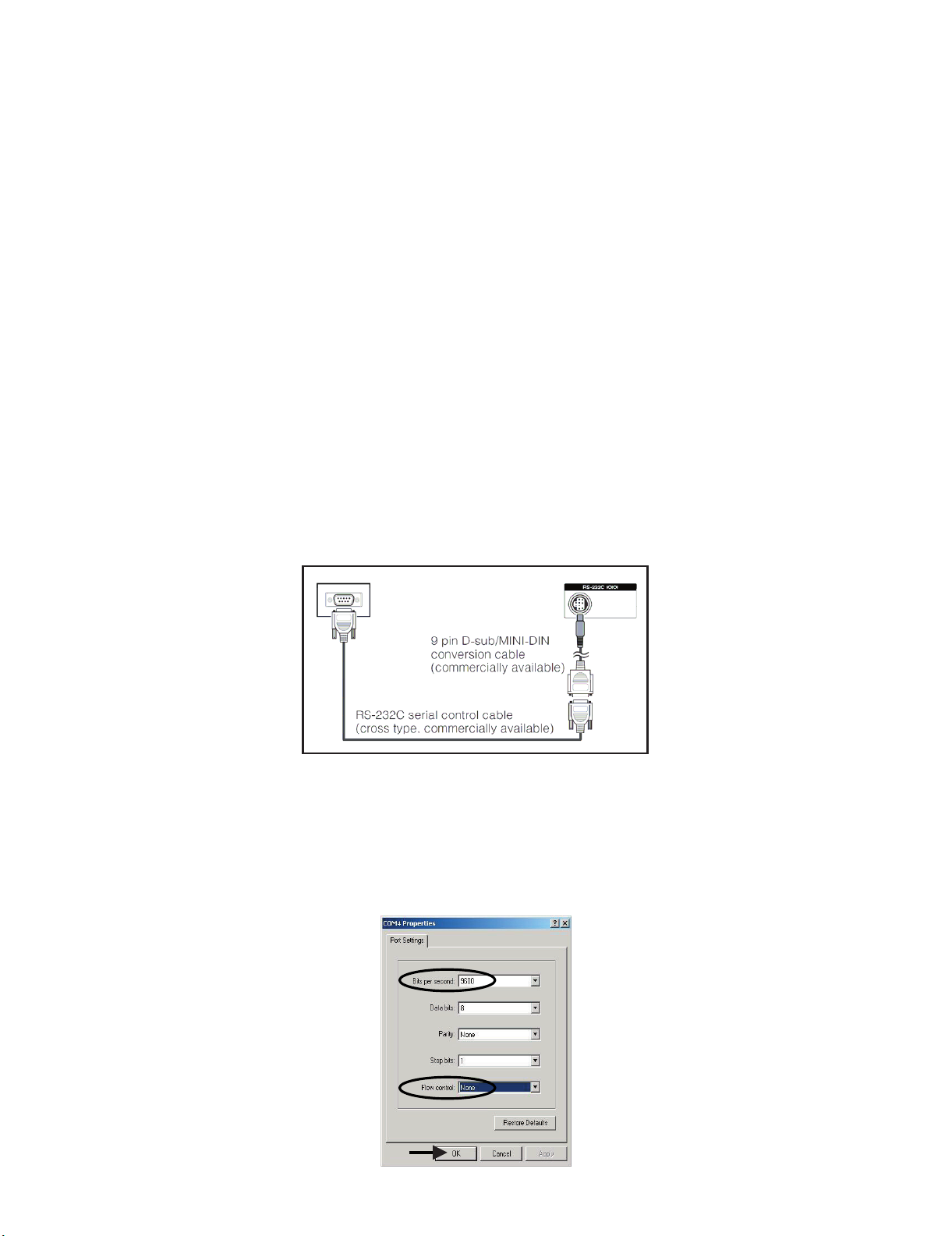
3. Make the connections as indicated in the figure:
Computer TV set
Before using RS-232C updating method is necessary to configure a Terminal PC software. HyperTerminal has been selected as a Terminal software because it’s include in all Windows versions as an accessory, and you can find it inside “Accessories\Communications” folder. For this reason, please follow carefully the next steps:
1) First time HyperTerminal is used, it’s necessary to configure some settings. Follows next action to configure two connection: low speed
(9600bps) and high speed (115200bps).
2) Create a New Connection file with name “P55_9600bps”.
3) Select a free COM port and select the Port Settings properties as follows:
5 – 1
Page 2
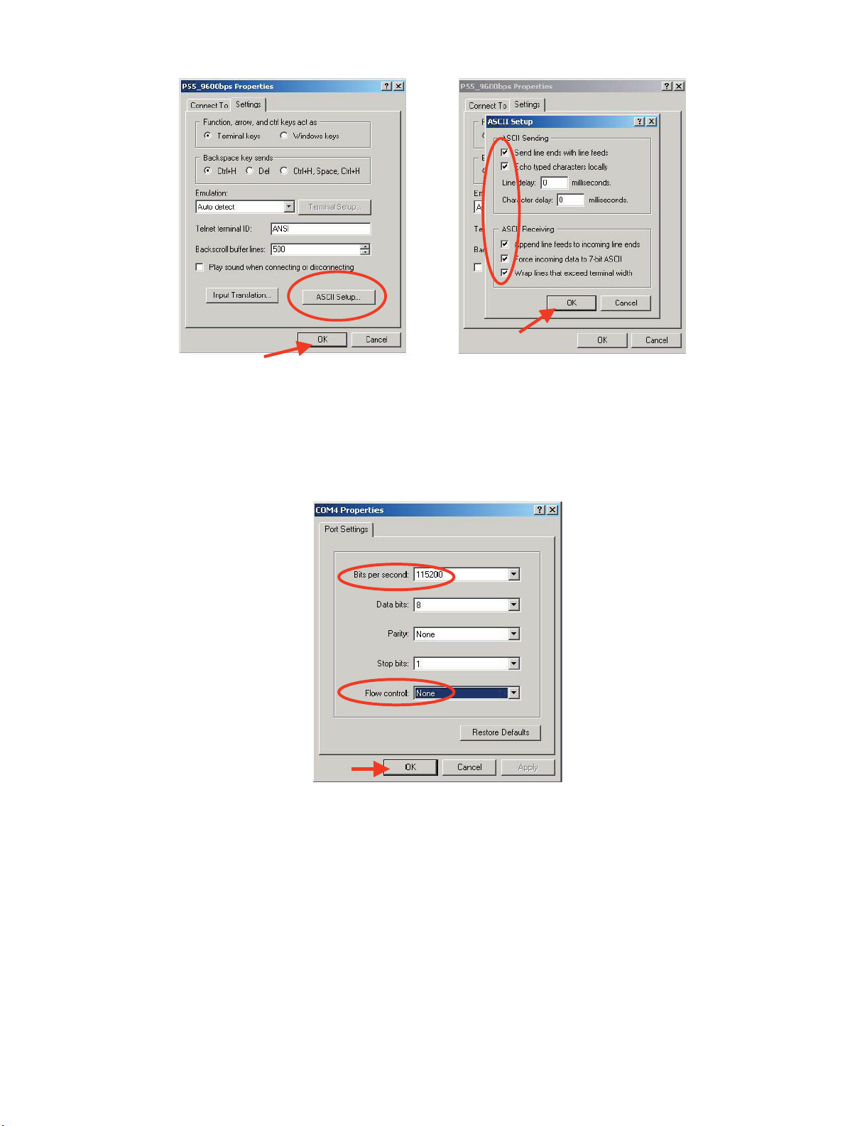
4) Click on “File\Properties” menu for selecting the General and ASCII properties as follows:
5) Select “New Connection” in the File Menu.
6) Answer “Yes” to close current connection and ”Yes” to save session “P55_9600bps”.
7) Create a new connection with the name “P55_115200bps”.
8) Select a the same COM port used in item 2 and select the Port Settings properties as follows:
LC-26SD1E/RU, LC-32SD1E/RU
9) Select the same General and ASCII properties as item 3.
10) Close HyperTerminal session, answering “Yes” to close current connection and “Yes” to save session “P55_115200bps”.
To start updating session, click over “P55_9600bps” icon that you can find in the “START\All programs\Accessories\ Communications\HyperTerminal\HyperTerminal” folder and follow next procedure:
5 – 2
Page 3
LC-26SD1E/RU, LC-32SD1E/RU
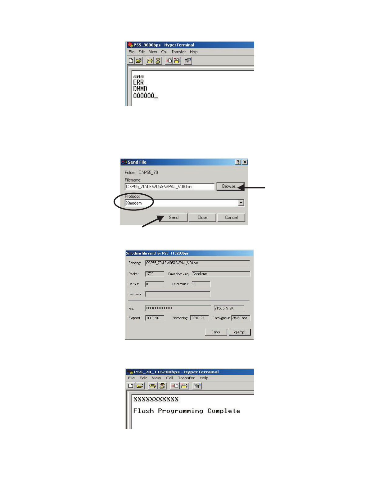
1) Check the connection between TV set and PC, sending a wrong command, as for example: “aaa”. TV set returns an “ERR” label as an syntaxis
ERROR (Not correct order or sequence).
2) Send the command “DWMD” to enter TV set in Download Mode. The TV set answer sending same symbol continuosly. If this symbol character
doesn’t appear, please don’t worry and pass to next step.
3) Close this connection and open “P55_115200bps” connection clicking over the “P55_115200bps” that you can find in “START\All programs\Accessories\ Communications\HyperTerminal\HyperTerminal” folder.
4) Using “Transfer\Send file...” menu, select desired file (.bin format) and the transmission protocol (Xmodem) as show below.
5) After press “Send” button the updating process starts as follows:
6) When flash update process finishes, the ”Flash Programming Complete” label appears in the screen, the device automatically go to switch off,
and in a few seconds go to switch on again.
VERY IMPORTANT NOTE:
During the updating time, please don’t use the PC for other purpouses, in order to abolish communication problems between TV set and
PC. If TV set was not updated properly, the TV won’t have the software to startup again, and you must follow the “I2C method” to update
another time the TV set.
5 – 3
Page 4
2. RS-232C Method Description (Tera Term)
The hardware tools requirement are:
1. A Modem-null (Cross type) DB9 female to DB9 female cable.
2. An adaptor DB9 male to mini-Din 9 pin male cable (Sharp Code: QCNWGA015WJPZ)
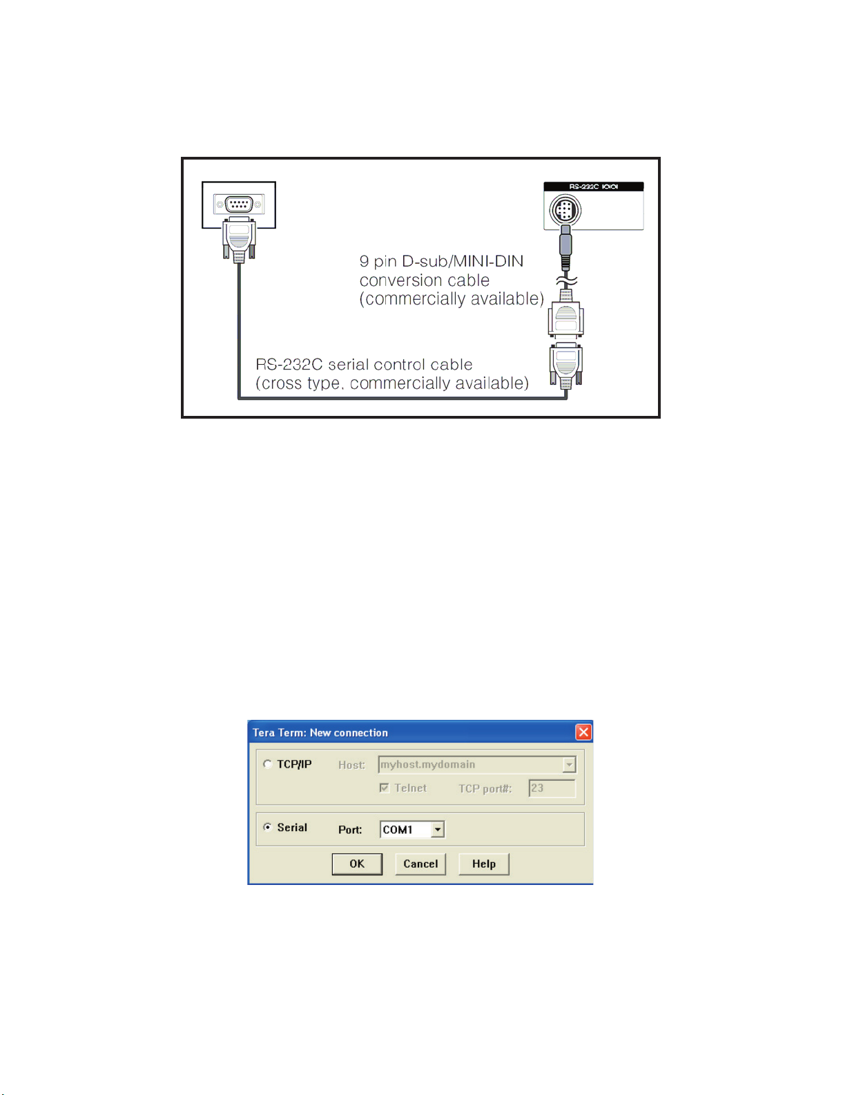
3. Make the connections as indicated in the figure:
Computer TV set
LC-26SD1E/RU, LC-32SD1E/RU
Software requirements :
To upgrade VCTp software from RS-232C external connector is necessary to use a Tera Term (Pro) free software.
The URL of Tera Term home page is:
http://hp.vector.co.jp/authors/VA002416/teraterm.html
(The address may be changed in future)
Tera Term (Pro) supported operating systems:
MS-Windows 95 or upper
MS-Windows NT 3.5 and 4.0 or upper
Note.- For Windows 3.1 use Tera Term version 1.X.
Copy all the distribution files to an empty floppy disk or temporary directory (for example C:\ TEMP).
Run SETUP.EXE and follow the instruction given by it.
After the installation, the distribution files are no longer needed, you can delete them or may keep them in the floppy disk.
Ho w to us e Tera Te rm P r o :
When the Tera Term (Pro) program is used, it’s necessary to shape some settings. Follows next action to configure the connection:
5 – 4
Page 5
LC-26SD1E/RU, LC-32SD1E/RU
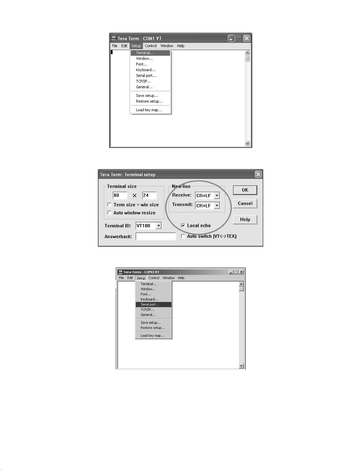
1) Select: Serial→COM X→ O.K.
2) Select: Termi nal
3) Choose the same options as the above picture.
5 – 5
Page 6
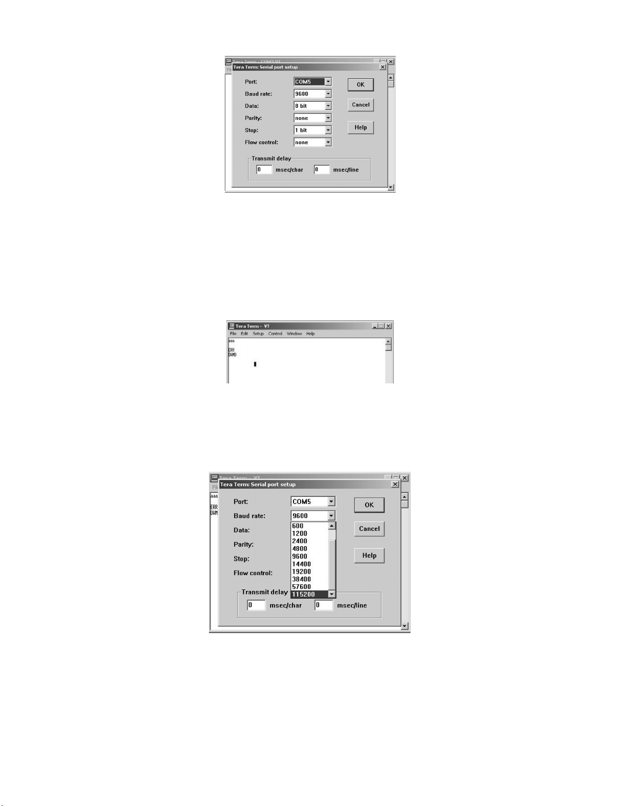
4) Select: Setup → Serial port → O.K. Appear the follow screen:
5) Select follows settings:
Serial port to use: COM x
Baud rate: 9600
Data: 8 bits
Parity: none
Stop: 1 bit
Flow control: none
Enter O.K.
LC-26SD1E/RU, LC-32SD1E/RU
6) Check the connection between TV set and PC, sending a wrong command, as for example: “aaa”. TV set returns an “err” label as an syntaxes
ERROR (Not correct order or sequence).
Send a “DWMD” (capital letters) command to enter TV set in Download Mode.
Change a baud rate to 115200.
Select: Setup → Baud rate → 115200 → O.K.
5 – 6
Page 7
LC-26SD1E/RU, LC-32SD1E/RU
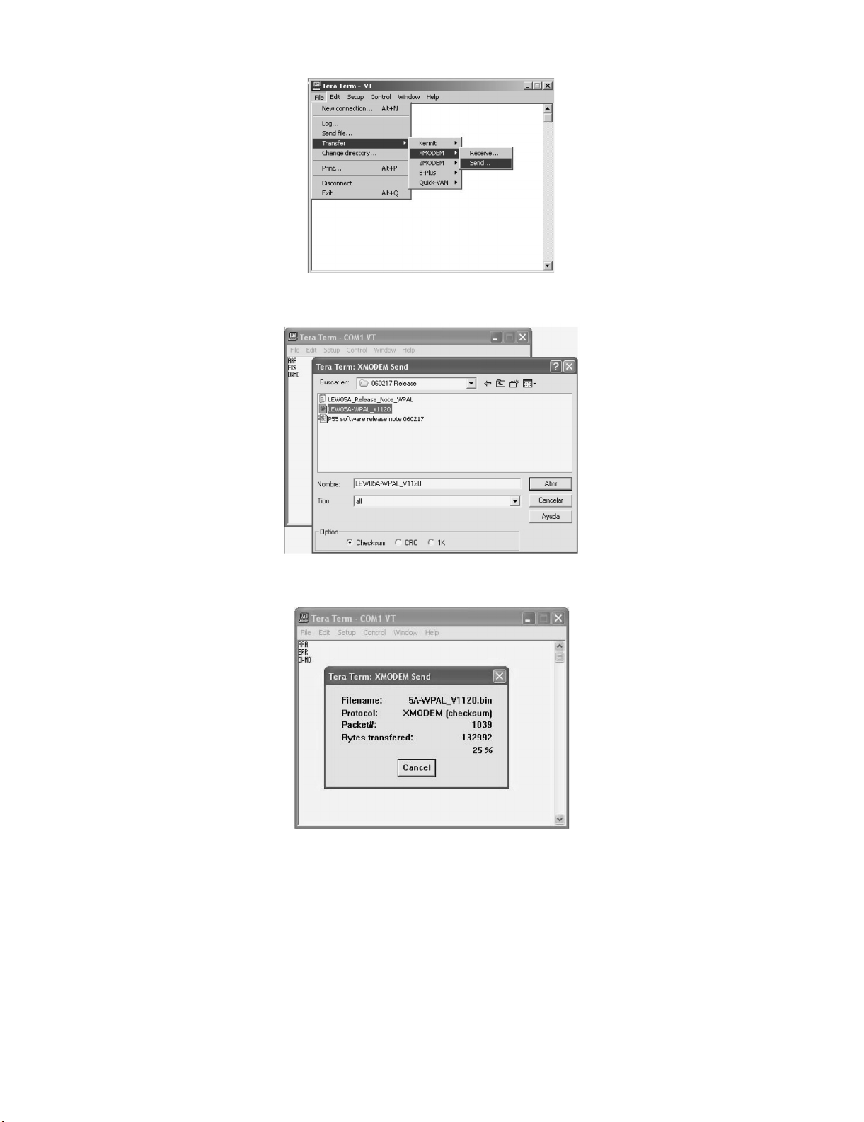
7) Select: File → Transfer → XMODEM → Sent
8) Choose the file for upgrade and click “Open”.
9) After select “Open” the upgrade process starts as follows:
5 – 7
Page 8
LC-26SD1E/RU, LC-32SD1E/RU
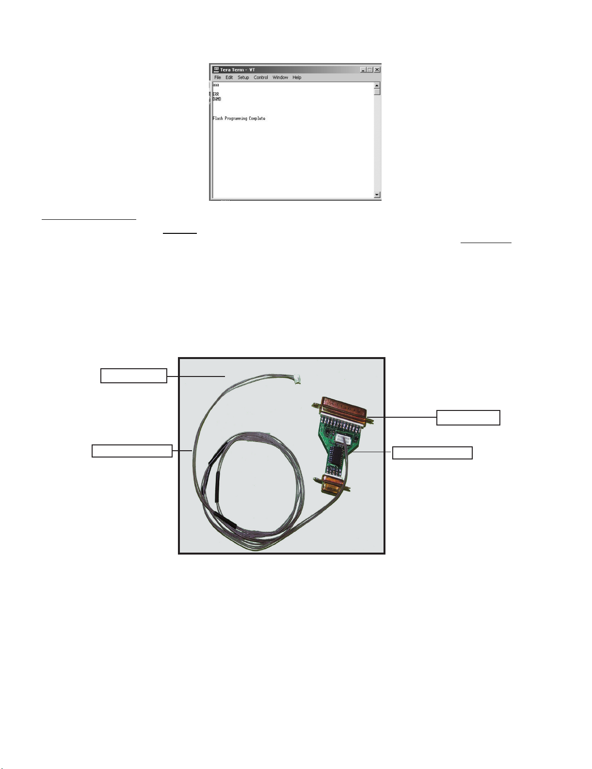
10) When flash update process finishes, the “Flash programming complete” label appear in the screen, the device automatically go to switch off, and
in a few seconds go to switch on again.
VERY IMPORTANT NOTE:
During the updating time, please don’t use the PC for other purposes, in order to abolish communication problems between TV set and PC.
If TV set was not updated properly, the TV won’t have the software to startup again, and you must follow the “I2C method”
another time the TV set.
3. I2C Method Description
The hardware tools requirement are:
1. A Parallel port I2C interface with 20 pin to 3 pin cable (Sharp Code: CKIT-0004WJV0).
2. Make the connections as indicated below:
i) Connect Parallel port I2C interface to LPT port of the computer.
ii) Connect the 20 to 3 pin cable from the I2C interface to the P2306 socket in the main board (XD603).
to update
To P2306
To PC
QCNWGA100WJZZ
QPWBX0004WJZZ
I2C Interface (CKIT-0004WJV0)
Before using I2C method is necessary to install Visual I2C software following next procedure.
1. Install Visual I2C release V3.2.3b from file (“Setup_Visual_I2C_v3-2-3b8h.exe”).
• It’s strongly recommended to accept the suggested default folder (“C:\Program Files\Micronas\Visual I2C”).
2. Install Visual I2C VCTp extension from file (“Setup_VI2C_for_VCT6wxyP_v0111.exe”).
• It’s interesting to change default folder to same as Visual I2C (“C:\Program Files\Micronas\Visual I2C”).
• During this installation process is possible to install also a complementary software to manage NVM memories.
This installation is not needed, for this reason uncheck the option when the setup program ask to you. In case of installation it’s interesting to change
default folder to same as Visual I2C (“C:\Program Files\Micronas\Visual I2C”).
3. Install Parallel driver depending of your Windows version from existing files inside the Visual I2C installation folder “C:\Program Files\Micro
nas\Visual I2C\Port_Driver”, following next criteria:.
1) Windows 98/Me (“Setup_LptDrv_v0104_9x.exe”).
2) Windows NT (“Setup_LptDrv_v0104_NT_2000.exe”).
5 – 8
Page 9
LC-26SD1E/RU, LC-32SD1E/RU
3) Windows Xp/2000 (“Setup_LptDrv_v020201_XP_2000.exe”).
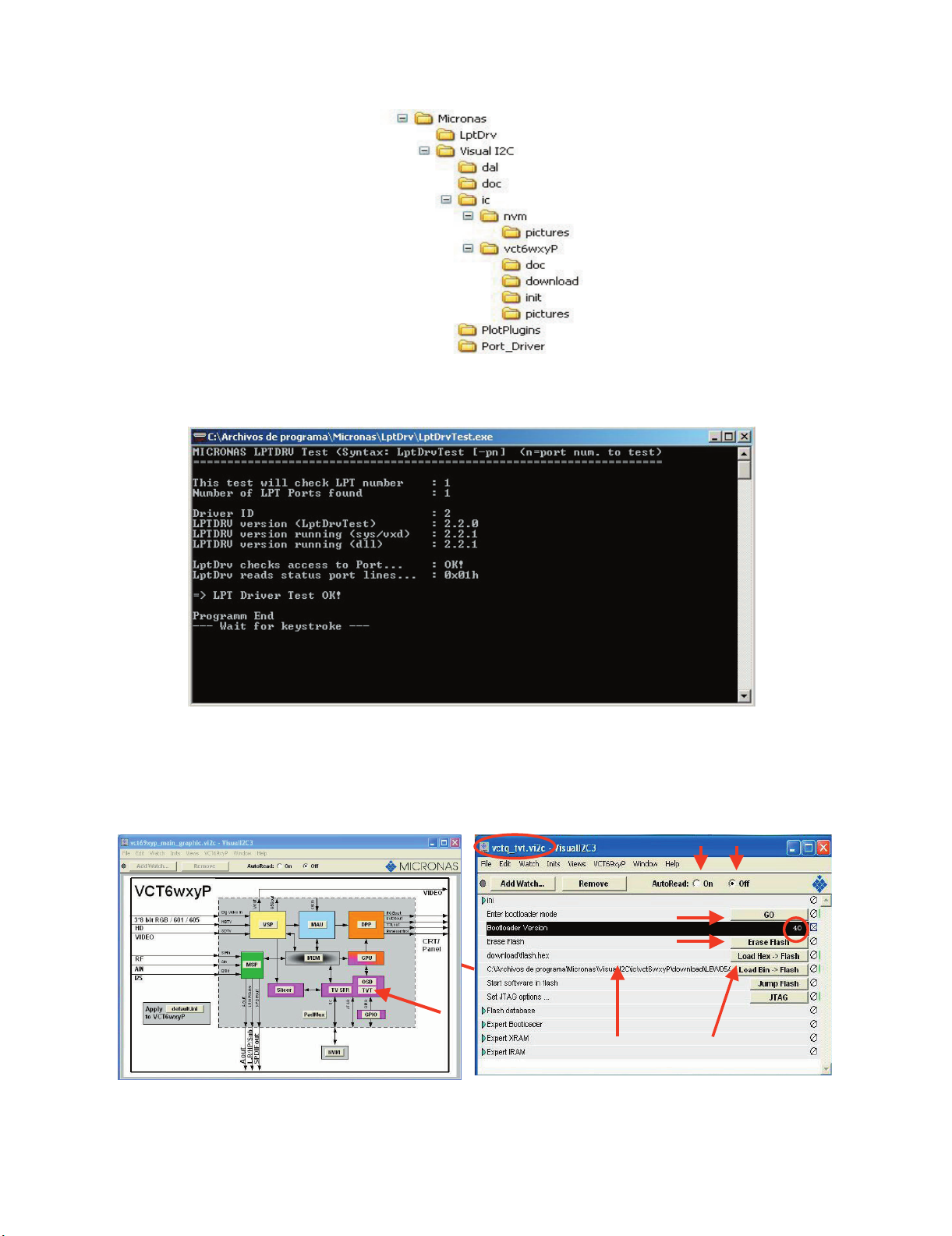
After installing Visual I2C, the new generated file structure should look like this:
4. Check installation LPT driver using “C:\Program Files\Micronas\LptDrv\LptDrvTest.exe”. After run this software, if LPT driver is installed properly
must appear this screen:
3.
• If the result is not OK, check inside PC bios: Parallel Port Mode=EPP
To run VCTp software update program, please click over “VCTP” icon from “START\All programs\Micronas\Visual I2C\IC\VCTP” and after Visual I2C
finish their starting process click on “TVT” module. As additional method, it’s possible to create a direct access to “C:\Program Files\Micronas\Visual
I2C\ic\vct6wxyP\vctq_tvt.vi2c” and launch it from Windows Desktop.
1
5
2
4
2
4
3
67
67
5 – 9
Page 10

LC-26SD1E/RU, LC-32SD1E/RU
To start updating process follow next instructions:
1. Set Autoread in ON option.
2. Click on “GO” button.
3. Wait until “40” appears in Bootloader Version field.
4. Close DOS pop up windows pressing any key (“Press any key to continue...”.).
5. Click on the “Erase flash” button and wait for a seconds and set the AutoRead to OFF.
6. Check in the desired software version is selected in the “Load BinaFlash” option. If it’s not the correct one, please double click on the file name and
select it. The first time this software is use it’s necessary to confirm write Addressing margin as from 0x0 to 0x7ffff.
7. Click on the “Load Bin → Flash” to start updating process.
8. When the updating process finishes, the “Progress” pop up window automatically closes. If appears some problem during the updating process a
error label appears in the filename information line.
If the TV has problem to enters in the “Bootloader mode”, it’s possible to force it by hardware method. This alternative method is described
below:
1. Switch off TV set or hold VCTp RESET line to GND.
2. Pull down SCL line (pin 1) to GND (pin 3) in P2306 connector.
3. Switch on TV set or release VCTp RESET line.
4. Release SCL pull down after minimum of 2 seconds.
5. Check if VCTp is in bootloader mode with Autoread setting in ON.
6. Wait until “40” appears in Bootloader Version field.
7. Follow instruction from item 5 on software method.
Sometimes, depending on the PC hardware, the progress bar runs very fast (Normal time: 1 minute) or some error message appears in the filename
information line. This means it’s necessary to modify some parameter of LPT port, for this reason select “LPT Preferences” on the “File\Preferences...” menu and increase Delay from “0” to “1” or “2” (normally, these values are the best choice).
5 – 10
Page 11

LC-26SD1E/RU, LC-32SD1E/RU
4. How to update the Digital Board Software.
There are 2 methods to update the Digital Board Software on Flash Memory (IC4203) throught the Digital Processor (IC4001).
• Jig RS-232 Method (From PC trough RS-232C COM port).
• PCMCIA CARD (Compact Flash Memory) Method.
NOTE: The PCMCIA method is only compatible with those PCs running XP Windows Version.
4.1. Jig RS-232 Method Description
• Hardware requirements:
1. A modem null (Cross type) DB9 female to DB9 female cable.
2. The Jig Kit (Sharp Code: QCNWKA012WJZZ)
3. Make the connections as in the below figure.
Computer
TV Set
(CI Terminal)
~
~
Jig
RS-232C serial control cable
(cross type, commercially available)
• Software requirements :
1. “Winupload” application software on PC.
5 – 11
Page 12

• How to setup the “Winupload” software for the first time:
1. Start “Winupload”. It will appear the following picture.
2. Select the most suitable RS232 Serial Port from “Port Setting” - “Process” Menu.
LC-26SD1E/RU, LC-32SD1E/RU
3. Select the following settings from “Port Settings” Menu.
Bits Per Second: 115200
Parity: None
Data bits: 8
Stop bits: 1
Hardware Flow Control: OFF
• Procedure for updating the TV set.
1. Switch off the TV set to be updated, in DTV mode.
2. Start “Winupload”. It will appear the following picture on PC.
5 – 12
Page 13

LC-26SD1E/RU, LC-32SD1E/RU
3. Establish connection on Winupload Software.
4. Select “Upload URT file”
5. Select and open the “.urt” data file from data directory
NOTE: Consider the version shown below just an example, may be is not the latest one, and could be different depending on the TV set destination
(market/Country) or model.
6. Switch On the TV Set (previously in DTV Mode). The Uploading Process starts automatically.
5 – 13
Page 14

LC-26SD1E/RU, LC-32SD1E/RU
While the TV set is uploading the software, the following information is shown on the TV set screen.
Then, data transfer from PC to TV set finishes when the “Upload progress completed” label appears in the “Winupload” screen. Now, the TV set made
some additional verification (Items #2 to #7). When the full uploading process is finished, in the “Winupload” window appears the label “Preparing to
start application” for a new TV Set, and just now, in the TV screen of the updated set, appears a congratulations label (Item #8).
NOTE: Do not turn off the TV set while the software updating was in progress.
7. Unplug the AC cord.
8. Disconnect the Jig from TV Set.
• Software Version verification procedure.
1. Connect the AC cord and Switch On the TV Set.
2. Select DTV Menu on TV Set. The following On Screen Display will appear.
5 – 14
Page 15

LC-26SD1E/RU, LC-32SD1E/RU
3. Select “Version”. The updated version can be verified.
NOTE: Consider the version shown above just as example, may be is not the latest one, and could be different depending on the TV set destination
(market/Country) or model.
4.2. PCMCIA Card (Compact Flash) Method.
• Hardware requirements:
1. Compact Flash Memory Card.
2. PCMCIA Compact Flash Adapter or USB Multi Card Reader.
• Software requirements:
1. “StorageMediaManager1.0.1” application software, installed on PC.
2. “Loader 2.2” or higher application software, installed on DTV Set.
NOTE: Storage Media Manager only for Windows XP.
• How to prepare the CF Card using the “Storage Media Manager 1.0.1” (SMM):
1. Insert PCMCIA (Compact Flash (CF) + CF-Adapter)
2. Execute SMM. If SMM does not appear or a Windows Error Box appears, please verify there are no USB media drives connected to the PC.
NOTE: Consider that it's recommended remove unnecessary media during SMM execution. Probably, If you try to use an USB Multi Card Reader
with SMM doesn't work fine.
3. If the CF card has never been formatted for the SMM (is not same format type used in Windows), the SMM will show you the PCMCIA-CF drive as
a Windows Media Drives, hanged of the “My Computer” tree (“J” Drive in the picture showed below).
But, if the PCMCIA-CF card had been formatted previously by SMM, directly the PCMCIA-CF drive will appear in the SMM formatted Drives box
(Sharp Drives). Please go to Item #6.
5 – 15
Page 16

LC-26SD1E/RU, LC-32SD1E/RU
4. In case of not SMM formatted card, select PCMCIA-CD Drive and using the Right-Click Pop up Menu please format the Drive.
5. Formatting the CF card. Select “Yes” to confirm the action.
NOTE: All FC’s data of the inside are erased.
6. If SMM formatted card already appears under SHARP DRIVES box please continue, if not try to repeat from item #1. Select origin folder and “.img”
data file to be written in the CF card.
5 – 16
Page 17

LC-26SD1E/RU, LC-32SD1E/RU
7. First of all, select copy target drive and then use Drag & drop for the “.img” file.
8. Wait, copy is in process.
9. Copy is finished, when the Copying progress bar disappears and the name of data file appears in the File Box.
5 – 17
Page 18

LC-26SD1E/RU, LC-32SD1E/RU
10. Close SMM application.
11. Remove PCMCIA safely using the Windows Task bar pop up menu (Right-click over the Tray Icon).
12. Now, the PCMCIA-CF card is prepared to update the TV set.
Procedure to update the TV Set using PCMCIA-CF Card:
1. Switch Off the LCD TV Set.
2. Insert PCMCIA Card (already prepared according the details before given at “How to prepare the CF Card using the “Storage Media Manager
1.0.1” (SMM))”.
3. Switch On the LCD TV Set (it starts automatically the updating, Items #1 to #4).
4. Wait till the finishing indication is shown.
5. For checking the correct update, please Select DTV Menu on TV Set. The following On Screen Display will appear.
6. Select “Version”. The updated version can be verified.
5 – 18
Page 19

LC-26SD1E/RU, LC-32SD1E/RU
[3] Entering and exiting the adjustment process mode
1) Unplug the AC power cord of running TV set to force off the power.
2) While holding down the “VOL(-)” and ”INPUT” keys on the set at once, plug in the AC power cord to turn on the power. The letter appears on
K
the screen.
3) Next, hold down the ”VOL(-)” and ”P( )” keys on the set at once.
Multiple lines of orange characters appearing on the screen indicate that the set is now in the adjustment Process mode. If you fail to enter the
adjustment process mode (the display is the same as normal startup), retry the procedure.
4) To exit the adjustment process mode after the adjustment is done, unplug the AC power cord to force off the power. (When the power is turned off
with the remote controller, once unplug the AC power cord and plug it in again. In this case, wait 10 seconds or so before plugging.)
5) To remove “K” mode, just repeat steps 1 and 2. This time the letter K disappears from screen.
Caution : Use due care in handling the information described here lest the users should know how to enter the adjustment process mode. If the
settings are tampered with in this mode, unrecoverable system damage may result.
[4] Remote controller key operation and description of display in adjustment process mode.
1. key operation
Remote controller key Main unit key Function
P ( / ) P ( / )
VOL (+ / –) VOL (+ / –) Changing a selected item setting (+1/–1)
Cursor (UP/DOWN) —————— Turing a page (PREVIOUS/NEXT)
Cursor (LEFT/RIGHT) —————— Changing a selected line setting (+10/–10)
INPUT SOURCE
INPUT button Input source switching (toggle switching)
on remote controller
OK —————— Executing a function
Moving an item (line) by one (UP/DOWN)
(TV→EXT1→EXT2→EXT3→EXT4→EXT5)
(Not Operative)
* Input mode is switched automatically when relevant adjustment is started so far as the necessary input signal is available.
2. Description of display
(1) Current page/Total pages (3) Currently selected input
(2) Current page title
1/11
Main Version
Dev Version
Dev Loader Version
Pic Version
TEMP SENSOR
NORMAL STANDBY CAUSE
ERROR STANDBY CAUSE
[INFO] TV AUTO 32:EURO
(4) Current colour TV system
1.XX (XX/XX/XXX)
XX
XX
XX
XX
XX
XX
Inch Setting
(5) Destination
(32 just as example,
it may be: --/32/37)
Adjustment process
menu header
(7) Parameters
5 – 19
Page 20

LC-26SD1E/RU, LC-32SD1E/RU
[5] Adjustment process mode menu
The character string in brackets [ ] will appear as a page title in the adjustment process menu header.
Page Line Item Description Remarks (adjustment detail, etc.)
1/11 [INFO]
1 Main Version LEW05 00.03(2006/07/15x)5 Main microprocessor version
2 Dev Version xxxxxx DTV microprocessor version
3 Dev Loader Version xxxxxx DTV microprocessor-Loader version
4 Pic Version xxxxxx Pic MICON version
5 TEMP SENSOR xxxxxx
6 NORMAL STANDBY CAUSE 1 RC_STANDBY
7 ERROR STANDBY CAUSE [1] 0 00H 00M Error standby cause Total operating time before error
[2] 0 00H 00M
[3] 0 00H 00M
[4] 0 00H 00M
[5] 0 00H 00M
2/11 [INIT]
1 Factory Init (--/EURO/UK/ITALY/FRANCE/
RUSSIA)ENTER
2 Inch Setting (--/26/32/37/45) Inch present setting
3 Public Mode OFF/ON HOTEL MODE flag setting
4 Center Acutime xxH xxM Main operating hours
5 RESET OFF/ON Main operating hours reset
6 Backlight Acutime xxH xxM Backlight operating hours
7 RESET OFF/ON Backlight operating hours reset
8 Picture Read Pos X 0-xxx x-axis setting of picture data
9 Picture Read Pos Y 0-xxx y-axis setting of picture data
10 Picture Read ON/OFF Start/stop of picture data
3/11 [PAL.SECAM. N358]
1 RF-AGC ADJ ENTER RF-AGC auto adjustment execution
2 PAL+TUNER ADJ ENTER PAL TUNER auto adjustment execution
3 PAL ADJ ENTER PAL auto adjustment execution
4 TUNER ADJ ENTER TUNER auto adjustment execution
5 CONTRAST SD 32 PAL contrast adjustment
6 SECAM CB OFFSET 1 SECAM offset adjustment
7 SECAM CR OFFSET 1 SECAM offset adjustment
8 TUNER A DAC 32 TUNER DAC adjustment
9 RF AGC 20 RF AGC adjustment
4/11 [COMP 15K]
1 COMP 15K ADJ ENTER COMP15K auto adjustment execution
2 COMP 15K CONTRAST 32 Contrast adjustment
5/11 [HDTV]
1 HDTV CONTRAST 32 HDTV Contrast adjustment
6/11 [SMPTE]
1 RF-AGC ADJ ENTER RF-AGC auto adjustment execution
2 PAL+TUNER ADJ ENTER PAL TUNER auto adjustment execution
3 PAL ADJ ENTER PAL auto adjustment execution
4 TUNER ADJ ENTER TUNER auto adjustment execution
5 CONTRAST SD 32 PAL contrast adjustment
6 SECAM CB OFFSET 1 SECAM offset adjustment
7 SECAM CR OFFSET 1 SECAM offset adjustment
8 TUNER A DAC 34 TUNER DAC adjustment
9 RF AGC 25 RF AGC adjustment
7/11 [M GAMMA INFO]
1 M GAMMA IN 1 160 W/B adjustment, gradation 1 input setting
2 M GAMMA IN 2 320 W/B adjustment, gradation 2 input setting
3 M GAMMA IN 3 480 W/B adjustment, gradation 3 input setting
4 M GAMMA IN 4 640 W/B adjustment, gradation 4 input setting
5 M GAMMA IN 5 800 W/B adjustment, gradation 5 input setting
6 M GAMMA IN 6 960 W/B adjustment, gradation 6 input setting
7 M GAMMA WRITE OFF/ON EEP writing of adjustment values
8 M GAMMA RESET OFF/ON Initialization of adjustment values
Initialization to factory settings execution
5 – 20
Page 21

LC-26SD1E/RU, LC-32SD1E/RU
Page Line Item Description Remarks (adjustment detail, etc.)
8/11 [M GAMMA 1-3]
1 M GAMMA R 1 0 W/B adjustment, gradation 1R adjustment value
2 M GAMMA G 1 0 W/B adjustment, gradation 1G adjustment value
3 M GAMMA B 1 0 W/B adjustment, gradation 1B adjustment value
4 M GAMMA R 2 0 W/B adjustment, gradation 2R adjustment value
5 M GAMMA G 2 0 W/B adjustment, gradation 2G adjustment value
6 M GAMMA B 2 0 W/B adjustment, gradation 2B adjustment value
7 M GAMMA R 3 0 W/B adjustment, gradation 3R adjustment value
8 M GAMMA G 3 0 W/B adjustment, gradation 3G adjustment value
9 M GAMMA B 3 0 W/B adjustment, gradation 3B adjustment value
10 M GAMMA WRITE OFF/ON EEP writing of adjustment values
9/11 [M GAMMA 4-6]
1 M GAMMA R 4 0 W/B adjustment, gradation 4R adjustment value
2 M GAMMA G 4 0 W/B adjustment, gradation 4G adjustment value
3 M GAMMA B 4 0 W/B adjustment, gradation 4B adjustment value
4 M GAMMA R 5 0 W/B adjustment, gradation 5R adjustment value
5 M GAMMA G 5 0 W/B adjustment, gradation 5G adjustment value
6 M GAMMA B 5 0 W/B adjustment, gradation 5B adjustment value
7 M GAMMA R 6 0 W/B adjustment, gradation 6R adjustment value
8 M GAMMA G 6 0 W/B adjustment, gradation 6G adjustment value
9 M GAMMA B 6 0 W/B adjustment, gradation 6B adjustment value
10 M GAMMA WRITE OFF/ON EEP writing of adjustment values
10/11 [ETC]
1 EEP CLEAR OFF/ON Clear of all adjustment value
2 EEP CLEAR B OFF/ON Clear of setting value of B mode
3 STANDBYCAUSE RESET OFF/ON Reset of STANDBY CAUSE
4 AUTO INSTALLATION SW 0/1 1: * * * 0: * * *
5OPTION 0
6 COUNTRY (--/EURO/UK/ITALY/FRANCE/
RUSSIA)
7 L ERR RESET 0 LAMP ERR RESET Initializatio of L_ERR
8 L ERR STOP 0/1 LAMP ERR Inhibit L_LRR detection
9 DTV CLR ENTER Cear of DTV Setting
10 I2C-OFF ENTER BUS STOP
11/ 11 [ LCD ]
1 OSC FREQ50 144 INVERTER drive frequency setting
2 OSC FREQ60 144 INVERTER drive frequency setting
3 PWM FREQ50 1 Frequency setting for INVERTER dimmer
4 PWM FREQ60 1 Frequency setting for INVERTER dimmer
5 PWM FREQ 424 Dimmer frequency adjustment
6 PWM DUTY 227 Dimmer DUTY adjustment
7 PWM CTRL 0 Dimmer CONTROL adjustment
Destination setting
[6] Special features
* ERROR STANDBY CAUSE (Page 1/11)
The total time when the unit enters the standby due to operational error and cause of error are recorded on EEPROM as much as possible.
The values can be used to locate the fault for repair.
* EEP CLEAR (Page10/11)
Clear of process adjustment EEP value.
5 – 21
Page 22

[7] Video signal adjustment procedure
* The adjustment process mode menu is listed in Section 5.
1. Signal check
1. Signal generator level adjustment check (Adjustment to the specified level)
•Composite signal PAL : 0.7Vp-p ±0.02Vp-p (Pedestal to white level)
•15K component signal : Y level 0.7Vp-p ±0.02Vp-p (Pedestal to white level)
(50 Hz) PB, PR level 0.7Vp-p ±0.02Vp-p
2. Entering the adjustment process mode
1. Enter the adjustment process mode according to Section 3.
3. RF AGC adjustment
Adjustment point Adjustment Conditions Adjustment procedure
1 Setting [Signal]
PAL
Sprit Field Colour Bar
RF signal UV
[Terminal]
TUNER
•Feed the PAL Sprit Field colour bar signal to TUNER.
Signal level: 50 dB µV +0dB , -1dB (75Ω LOAD)
LC-26SD1E/RU, LC-32SD1E/RU
[RF Signal]
2 Auto adjustment
performance
Adjustment process
Page3
Bring the cursor on [ RF AGC ADJ] and press [OK]
[ RF AGC ADJ OK] appears when finished.
4. RF AGC Adjustment (SMPTE RF SIGNAL- Alternative Method)
Adjustment point Adjustment Conditions Adjustment procedure
1 Setting [Signal]
2 Auto adjustment
performance
PAL
SMPTE Field Colour Bar
RF signal
[Terminal]
TUNER
Adjustment process
Page6
•Feed the PAL SMPTE colour bar signal (E-12ch) to TUNER.
Signal level: 50 dB µV (75Ω LOAD)
Bring the cursor on [ RF AGC ADJ] and press [OK]
[ RF AGC ADJ OK] appears when finished.
㸡100% white
[TUNER]
100% white
5 – 22
Page 23

LC-26SD1E/RU, LC-32SD1E/RU
100% white 100% white
[EXT3] [TUNER]
5. PAL signal & tuner adjustment
Adjustment point Adjustment Conditions Adjustment procedure
1 Setting [Signal]
PAL
Full Field Colour Bar
Composite or RF signal
[Terminal]
EXT3 VIDEO IN
TUNER
•Feed the PAL full field colour bar signal (75% colour saturation) to
EXT3 VIDEO IN.
•Feed the RF signal (PAL colour bar) to TUNER.
•Make sure the PAL colour bar pattern has the sync level of 7:3 with
the picture level.
㪲VIDEO IN SIGNAL]
[RF Signal]
㸡100% white
2 Auto adjustment
performance
Adjustment process
Page3
Bring the cursor on [ PAL + TUNER ADJ] and press [OK]
[ PAL + TUNER ADJ OK] appears when finished.
6. PAL Signal & Tuner Adjustment (SMPTE RF SIGNAL-Alternative Method)
Adjustment point Adjustment Conditions Adjustment procedure
1 Setting [Signal]
PAL
FULL Field Colour Bar
Composite or RF SMPTE signal
[Terminal]
EXT3 VIDEO IN
TUNER
2 Auto adjustment
performance
Adjustment process
Page6
•Feed the PAL full field colour bar signal (75% color saturation) to
EXT3 VIDEO IN.
•Feed the RF signal SMPTE color bar (E-12) to TUNER.
•Make sure the SMPTE color bar pattern (E-12) has the sync level of
7:3 with the picture level.
Bring the cursor on [ PAL + TUNER ADJ] and press [OK]
[ PAL + TUNER ADJ OK] appears when finished.
㸡100% white
5 – 23
Page 24

7. ADC adjustment (Component 15K)
Adjustment point Adjustment Conditions Adjustment procedure
1 Setting [Signal]
COMP15K, 50Hz
100% Full Field Colour Bar
[Terminal]
EXT4 COMPONENT IN
LC-26SD1E/RU, LC-32SD1E/RU
•Feed the COMPONENT 15K 100% full field colour bar signal (100%
colour saturation) to EXT4 COMPONENT IN.
2 Auto adjustment
performance
Adjustment process
Page4
100% white
Bring the cursor on [ COMP15K ADJ] and press [OK]
[ COMP15K ADJ OK] appears when finished.
Black
[8] White Balance Adjustment
Adjustment gradation values (IN) appear on page 7/11 of process adjustment, and adjustment initial values (offset value) appear on pages 8/11 and
9/11. For white balance adjustment, adjust the offset values on pages 8/11 and 9/11.
[Condition of the unit for inspection] Modulated light: MAX (+8)
[Adjustment reference device] Minolta CA-210
[Adjustment]
Check that the values on page 7/11 of process adjustment are set as below. If not, change them accordingly.
M GAMMA IN 1 160 M GAMMA IN 2 320
M GAMMA IN 3 480 M GAMMA IN 4 640
M GAMMA IN 5 800 M GAMMA IN 6 960
1) Display the current adjustment status at point 6. (Page 8/11 of process adjustment)
The display for checking the adjustment status is toggled by pressing the “6” button on the remote control.
(Normal OSD display → “6”→ display for check (OSD disappears) → “6” →normal OSD display → • • •)
2) Read the value of the luminance meter.
3) Change M GAMMA R6/M GAMMA B6 (Adjustment offset value) on page 9/11 of process adjustment so that the values of the luminance meter
approach x =0.272 and y =0.277.
(Basically, G is not changed. If adjustment fails with R and B, change G. When G is lowered, the weaker of R and B must be fixed.)
4) If G is changed in step 3), change the values of M GAMMA G1-M GAMMA G5 on pages 8/11 and 9/11 of process adjustment as follows. When
not changed, go to step5).
Offset value of M GAMMA G1 = (Offset value of M GAMMA G6) * (160/960)
Offset value of M GAMMA G2 = (Offset value of M GAMMA G6) * (320/960)
Offset value of M GAMMA G3 = (Offset value of M GAMMA G6) * (480/960)
Offset value of M GAMMA G4 = (Offset value of M GAMMA G6) * (640/960)
Offset value of M GAMMA G5 = (Offset value of M GAMMA G6) * (800/960)
5) Display the adjustment status of the current point 5. (Each time the “5” button on the remote control is pressed, the adjustment status check display is toggled.)
(Normal OSD display → “5” → Check display (OSD disappears) → “5” → Normal OSD display → • • •)
Change M GAMMA R5/M GAMMA B5 (adjustment offset value) on page 9/11 of process adjustment so that the values of the luminance meter
approach x = 0.272 and y = 0.277.
6) Repeat step 5) for points 4, 3, 2, and 1.
5 – 24
Page 25

LC-26SD1E/RU, LC-32SD1E/RU
[9] QS Temperature NVM Data Confirmation
During servicing of the LCD TV set, by software upgrading or by any cleaning NVM, it’s mandatory select the “Inch Setting” in Service Mode, Page 2,
according to the size of the TV set.
[10] Initialization to factory settings
Caution: When the factory settings have been made, all user setting data, including the channel settings, are initialized. (The adjust-
ments done in the adjustment process mode are not initialized.) Keep this in mind when initializing these settings.
Adjustment item Adjustment conditions Adjustment procedure
1 Factory settings See to below caution •Enter the adjustment process mode.
After adjustments, exit the adjustment process mode.
To exit the adjustment process mode, unplug the AC power cord from the outlet to forcibly turn off the power.
When the power is turned off with the remoto control, unpulug the AC power cord and plug it back in (wait apporximately 10 seconds before plugging in the AC power cord).
•Bring the cursor to [Factory Init] on page 2/11.
•Use the [Volume +-] key to select a region from [EURO/UK/ITALY/
FRANCE/RUSSIA]and press the [ENTER].
“EXECUTING” appears and initialization starts.
After a while,”***OK***” appears and the setting is complete.
Note: Never turn the power off during initialization.
The folloeing settings will be back to their factory ones.
1. User settings
2. Channel data (e.g. broadcast frequencies)
3. Password data
5 – 25
Page 26

LC-26SD1E/RU, LC-32SD1E/RU
[11] Lamp error detection
1. Function description
This LCD colour television has a function (lamp error detection) to be turned OFF automatically (Inverter unit) for safety when the lamp or lamp circuit
is abnormal.
If the lamp or lamp circuit is abnormal, or some other errors happen, and the lamp error detection is executed, the following occur.The Inverter circuit
stops but the rest of TV continues working. The power led is green.
2. Countermeasures
Proceed to repair the inverter unit to solve the problem that produces the lamp error.
3. Reset standby cause error list
For 26/32” this is not necessary because the lamp error detection is not operative by software.
[12] Public Mode (Hotel Mode)
1. How to Enter in the Public Mode (Hotel Mode).
Turn on the power and enter in the Adjustment Process mode (ADJ1 or Service Mode) as usual.
In the [INIT], Page 2/11 of Service, turns ON the Public Mode option.
Turn off TV by pressing Main Power switch.
While pressing “VOL+” and “P^” keys at the same time, press Main Power switch for more than 2 seconds.
After this sequence the TV will turn on showing the Public Mode setting screen as follows:
Is possible to select each item of function by pressing cursor UP/DOWN keys on the remote control or CH( )( ) keys on the LCD TV.
The setting position of each item of functions is made by pressing cursor RIGHT/LEFT keys on the remote control or VOL(+)(-) keys on the LCD TV.
Select EXECUTE position after you set all function, and press cursor RIGHT/LEFT keys on the remote control or VOL(+)/(-) keys on the LCD TV for
confirmation.
2. Public Mode Settings.
1. POWER ON FIXED [VARIABLE FIXED]
When it is set to “FIXED” the TV is impossible to be switch off by Main Switch or Remote Control.
2. MAXIMUM VOLUME [0 60]
Is possible to set the maximum volume at limited level.
3. VOLUME FIXED [VARIABLE FIXED]
Is possible to fix the sound volume at limited level.
When “FIXED” is selected the sound volume before limited is fixed.
4. VOLUME FIXED LEVEL [0 60]
If “FIXED” has been selected, is possible to set a fixed volume at the level that is chosen.
5. RC BUTTON [RESPOND NO RESPOND]
If “NO RESPOND” is selected, the remote control keys are inoperative.
6. PANEL BUTTON [RESPOND NO RESPOND]
If “NO RESPOND” has been selected, the set’s keys remain deactivated (Except POWER key).
5 – 26
Page 27

LC-26SD1E/RU, LC-32SD1E/RU
7. MENU BUTTON [RESPOND NO RESPOND]
If “NO RESPOND” has been selected, “MENU” key, of remote control, is inoperative.
8. ON SCREEN DISPLAY [YES NO]
If “NO” has been selected, the On Screen Display does not appear.
9. INPUT MODE START [ NORMAL → TV (X) → INPUT1 → INPUT2 → INPUT3 → INPUT4 → INPUT5 ]
When any other item than “NORMAL” has been selected, the sets will start in a selected input mode at the next power-on.
10.INPUT MODE FIXED [VARIABLE → FIXED]
“FIXED” has been selected, any channels and input modes other than those selected at the start mode cannot be picked up.
11.RESET
Cancel all Public Mode settings. (It returns to the factory settings)
12.EXECUTE
Select this item, and press cursor RIGHT/LEFT keys on the remote control or VOL(+)/(-) keys on the LCD TV for confirmation the functions settings.
5 – 27
 Loading...