

Page 1
LC-32GD6U
LC-37GD6U
SERVICE MANUAL
S84Z2LC37GD6U
LCD COLOR TELEVISION
LC-32GD6U
MODELS
In the interests of user-safety (Required by safety regulations in some countries) the set should be restored
to its original condition and only parts identical to those specified should be used.
OUTLINE
This model is based on the LC-32/37GD4U and is equipped with a redesigned speaker. This Service Manual
covers the modifications alone. For the other points, refer to the LC-32/37GD4U Service Manual.
CONTENTS
» LIST OF CHANGED PARTS ...........................................................................................................................2
» IMPORTANT SERVICE SAFETY PRECAUTION ........................................................................................4
» SPECIFICATIONS........................................................................................................................................7
» OPERATION MANUAL ................................................................................................................................8
» DIMENSIONS ............................................................................................................................................14
» REMOVING OF MAJOR PARTS................................................................................................................15
» DESCRIPTION OF SCHEMATIC DIAGRAM .............................................................................................21
» SCHEMATIC DIAGRAM.............................................................................................................................22
» PARTS LIST ...............................................................................................................................................23
» PACKING OF THE SET .............................................................................................................................33
LC-37GD6U
Page
SHARP CORPORATION
This document has been published to be used for
after sales service only.
The contents are subject to change without notice.
Page 2
LC-32GD6U
LC-37GD6U
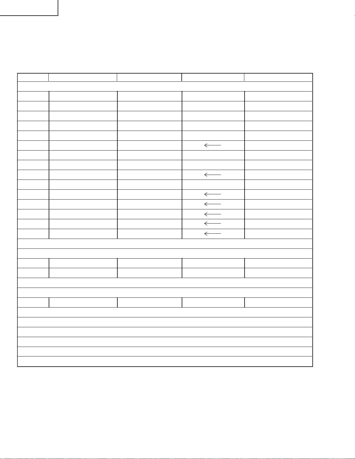
LIST OF CHANGED PARTS
LC-32GD4U → LC-32GD6U
Ref.No. Description LC-32GD4U LC-32GD6U Note
PWB ASSEMBLIES
AV Unit DUNTKC664UJ02 DUNTKC664UJ01 No parts changed
KEY Unit DUNTKC665UJ02 DUNTKC665UJ01 No Parts changed
R/C LED Unit DUNTKC666UJ02 DUNTKC666UJ01 No parts changed
EXT SP TERMINAL Unit DUNTKC667UJ02 DUNTKC667UJ01 One parts changed
FRONT Unit DUNTKC668UJ02 DUNTKC668UJ01 No parts changed
DVI Unit DUNTKC267VJ27
LCD CONTROL Unit DUNTKC268VJ24 DUNTKC268VJ23 Some Parts changed
DIGITAL Unit DKEYDC307VJ13 DKEYDC307VJ12 No parts changed
PC CARD Unit DUNTKC544VJ03
MAIN Unit DUNTKC641VJ04 DUNTKC641VJ03 No parts changed
POWER Unit RDENCA067WJZZ
INVERTER-A Unit RUNTKA069WJN1
INVERTER-B Unit RUNTKA070WJN1
INVERTER-A GND Unit RUNTKA071WJZZ
INVERTER-B GND Unit RUNTKA072WJZZ
LCD CONTROL Unit
R2026 Metal Oxide VRS-CY1JF223JY Add
R2029 Metal Oxide VRS-CY1JF223JY Delete
EXT-SP Unit
J203 Terminal, 4Pin QTANAA003WJZZ QTANAA004WJZZ Parts Changed
CABINET AND MECHANICAL PARTS
Please refer to a Parts list.
PACKING PARTS AND ACCESSORIES
Please refer to a Parts list.
2
Page 3
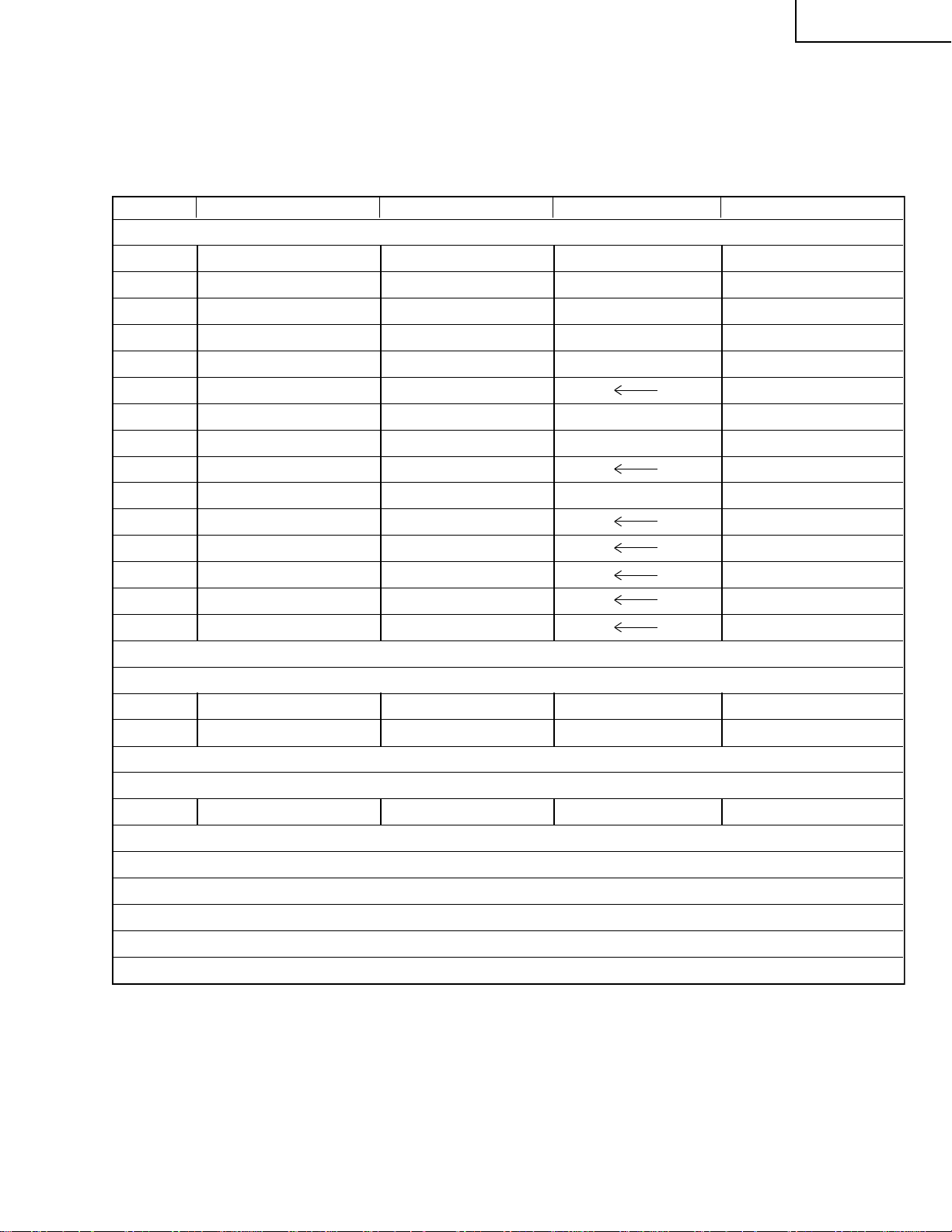
LIST OF CHANGED PARTS
LC-37GD4U → LC-37GD6U
Ref.No. Description LC-37GD4U LC-37GD6U Note
PWB ASSEMBLIES
AV Unit DUNTKC664UJ04 DUNTKC664UJ03 No parts changed
KEY Unit DUNTKC665UJ04 DUNTKC665UJ03 No Parts changed
R/C LED Unit DUNTKC666UJ04 DUNTKC666UJ03 No parts changed
EXT SP TERMINAL Unit DUNTKC667UJ04 DUNTKC667UJ03 One parts changed
FRONT Unit DUNTKC668UJ04 DUNTKC668UJ03 No parts changed
DVI Unit DUNTKC267VJ29
LCD CONTROL Unit DUNTKC268VJ26 DUNTKC268VJ25 Some Parts changed
DIGITAL Unit DKEYDC307VJ15 DKEYDC307VJ14 No parts changed
PC CARD Unit DUNTKC544VJ03
MAIN Unit DUNTKC641VJ06 DUNTKC641VJ05 No parts changed
LC-32GD6U
LC-37GD6U
POWER Unit RDENCA067WJZZ
INVERTER-A Unit RUNTKA080WJN1
INVERTER-B Unit RUNTKA081WJN1
INVERTER-A GND Unit RUNTKA082WJZZ
INVERTER-B GND Unit RUNTKA083WJZZ
LCD CONTROL Unit
R2026 Metal Oxide VRS-CY1JF223JY Add
R2029 Metal Oxide VRS-CY1JF223JY Delete
EXT-SP Unit
J203 Terminal, 4Pin QTANAA003WJZZ QTANAA004WJZZ Parts Changed
CABINET AND MECHANICAL PARTS
Please refer to a Parts list.
PACKING PARTS AND ACCESSORIES
Please refer to a Parts list.
3
Page 4
LC-32GD6U
2
2
LC-37GD6U
IMPORTANT SERVICE SAFETY PRECAUTION
Ë
Service work should be performed only by qualified service technicians who are thoroughly familiar with all safety checks and the servicing guidelines which follow:
WARNING
» Use an AC voltmeter having with 5000 ohm per volt,
or higher, sensitivity or measure the A C v oltage drop
1. For continued safety, no modification of any circuit
should be attempted.
2. Disconnect AC power before servicing.
across the resistor.
» Connect the resistor connection to all exposed metal
parts having a return to the chassis (antenna, metal
cabinet, screw heads, knobs and control shafts,
escutcheon, etc.) and measure the AC voltage drop
across the resistor.
All checks must be repeated with the AC cord plug
connection reversed. (If necessary, a nonpolarized
adaptor plug must be used only for the purpose of
completing these checks.)
Any reading of 0.75V rms (this corresponds to 0.5
mA rms AC.) or more is excessive and indicates a
potential shock hazard which must be corrected
A V
CAUTION: FOR CONTINUED
PROTECTION AGAINST A RISK OF
FIRE REPLACE ONLY WITH SAME
TYPE FUSE.
LC-32GD6U: F1701, F1702 (6.3A, 250V),
LC-32GD6U: F1703 (2.0A, 250V)
LC-32GD6U: F7401,F7501 (6.3A, 250V)
LC-37GD6U: F7403,F7503 (10A, 250V)
before returning the monitor to the owner.
BEFORE RETURNING THE RECEIVER
(Fire & Shock Hazard)
Before returning the receiver to the user, perform
the following safety checks:
1. Inspect all lead dress to make certain that leads are
not pinched, and check that hardware is not lodged
between the chassis and other metal parts in the
receiver.
2. Inspect all protective devices such as non-metallic
control knobs, insulation materials, cabinet backs,
adjustment and compartment covers or shields,
isolation resistor-capacitor networks, mechanical
insulators, etc.
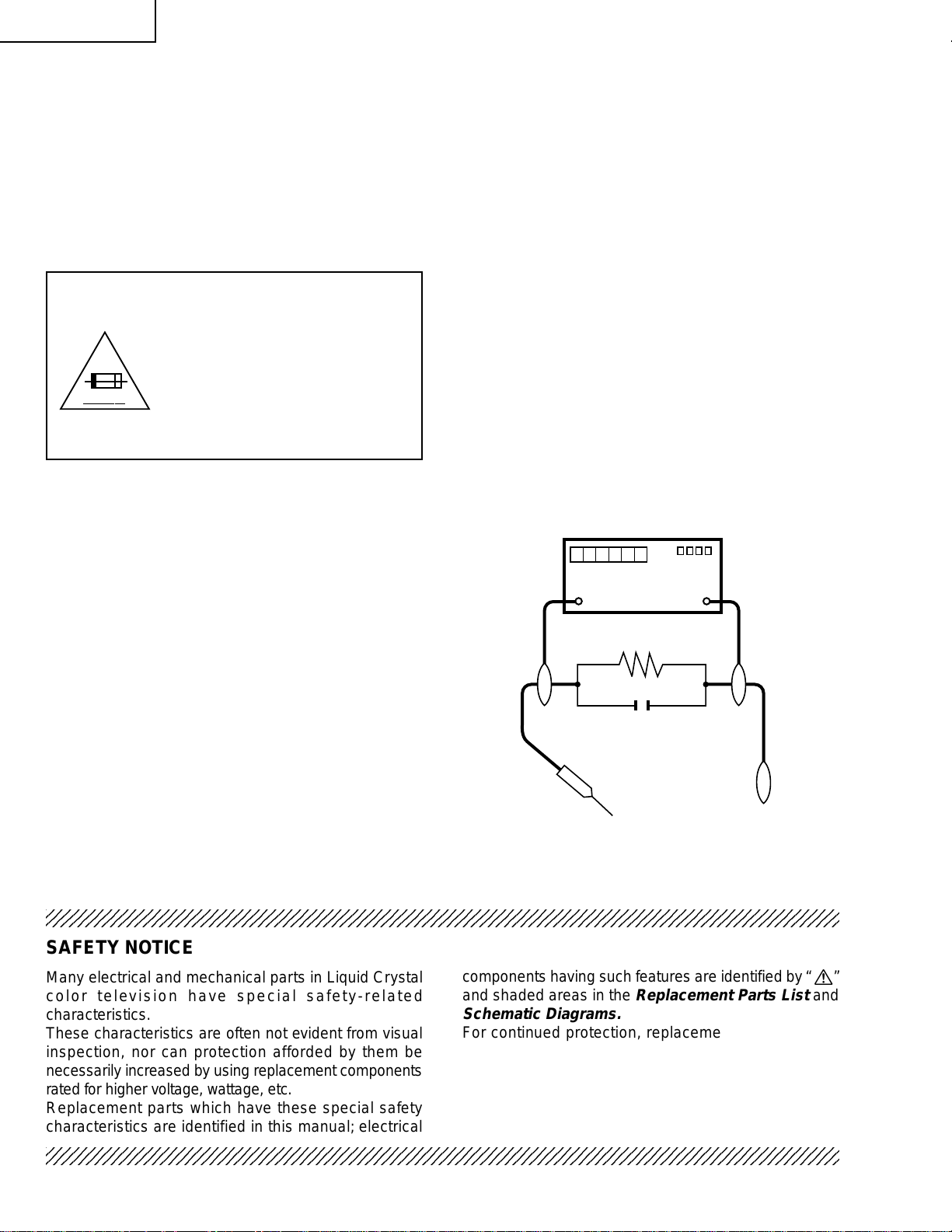
3. To be sure that no shock hazard exists, check for
leakage current in the following manner.
» Plug the AC cord directly into a 120 volt AC outlet.
» Using two clip leads, connect a 1.5k ohm, 10 watt
resistor paralleled by a 0.15µF capacitor in series
with all exposed metal cabinet parts and a known
TO EXPOSED
METAL PARTS
earth ground, such as electrical conduit or electrical
ground connected to an earth ground.
234567890123456789012345678901212345678901234567890123456789012123456789012345678901234567890121
DVM
AC SCALE
1.5k ohm
10W
0.15 µF
TEST PROBE
CONNECT TO
KNOWN EARTH
GROUND
SAFETY NOTICE
Many electrical and mechanical parts in Liquid Cr ystal
color television have special safety-related
characteristics.
These characteristics are often not evident from visual
inspection, nor can protection afforded by them be
necessarily increased by using replacement components
rated for higher voltage, wattage, etc.
Replacement parts which have these special safety
characteristics are identified in this manual; electrical
234567890123456789012345678901212345678901234567890123456789012123456789012345678901234567890121
components having such features are identified b y “ å”
and shaded areas in the
Replacement Parts List
Schematic Diagrams.
For continued protection, replacement parts must be
identical to those used in the original circuit.
The use of a substitute replacement parts which do not
have the same safety characteristics as the factory
recommended replacement parts shown in this service
manual, may create shock, fire or other hazards.
4
and
Page 5
LC-32GD6U
2
2
2
LC-37GD6U
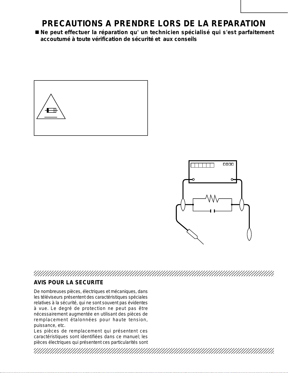
PRECAUTIONS A PRENDRE LORS DE LA REPARATION
Ë
Ne peut effectuer la réparation qu' un technicien spécialisé qui s'est parfaitement
accoutumé à toute vérification de sécurité et aux conseils suivants.
AVERTISSEMENT
1. N'entreprendre aucune modification de tout circuit.
C'est dangereux.
2. Débrancher le récepteur avant toute réparation.
PRECAUTION: POUR LA
PRO TECTION CONTINUE CONTRE
LES RISQUES D'INCENDIE,
REMPLACER LE FUSIBLE
LC-32GD6U: F1701, F1702 (6.3A, 250V),
A V
LC-32GD6U: F1703 (2.0A, 250V)
LC-32GD6U: F7401,F7501 (6.3A, 250V)
LC-37GD6U: F7403,F7503 (10A, 250V)
VERIFICATIONS CONTRE L'INCEN-DIE ET
LE CHOC ELECTRIQUE
Avant de rendre le récepteur à l'utilisateur, effectuer
les vérifications suivantes.
1. Inspecter tous les faisceaux de câbles pour s'assurer
que les fils ne soient pas pincés ou qu'un outil ne soit
pas placé entre le châssis et les autres pièces
métalliques du récepteur.
2. Inspecter tous les dispositifs de protection comme les
boutons de commande non-métalliques, les isolants,
le dos du coffret, les couvercles ou blindages de réglage
et de compartiment, les réseaux de résistancecapacité, les isolateurs mécaniques, etc.
3. S'assurer qu'il n'y ait pas de danger d'électrocution en
vérifiant la fuite de courant, de la facon suiv ante:
• Brancher le cordon d'alimentation directem-ent à une
prise de courant de 120V. (Ne pas utiliser de
transformateur d'isolation pour cet essai).
• A l'aide de deux fils à pinces, brancher une résistance
de 1.5 kΩ 10 watts en parallèle a v ec un condensateur
de 0,15µF en série avec toutes les pièces métalliques
exposées du coffret et une terre connue comme une
conduite électrique ou une prise de terre branchée à
la terre.
• Utiliser un voltmètre CA d'une sensibilité d'au moins
5000Ω/V pour mesurer la chute de tension en travers
de la résistance.
• Toucher avec la sonde d'essai les pièces métalliques
exposées qui présentent une voie de retour au châssis
(antenne, coffret métallique, tête des vis, arbres de
commande et des boutons, écusson, etc.) et mesurer
la chute de tension CA en-travers de la résistance.
Toutes les vérifications doivent être refaites après avoir
inversé la fiche du cordon d'alimentation. (Si nécessaire,
une prise d'adpatation non polarisée peut être utilisée
dans le but de terminer ces vérifications.)
Tous les courants mesurés ne doivent pas dépasser
0.7 mA.
Dans le cas contraire, il y a une possibilité de choc
électrique qui doit être supprimée avant de rendre le
récepteur au client.
DVM
ECHELLE CA
1.5k ohm
10W
0.15 µF
SONDE D'ESSAI
AUX PIECES
METALLIQUES
EXPOSEES
BRANCHER A UNE
TERRE CONNUE
234567890123456789012345678901212345678901234567890123456789012123456789012345678901234567890121
234567890123456789012345678901212345678901234567890123456789012123456789012345678901234567890121
AVIS POUR LA SECURITE
De nombreuses pièces, électriques et mécaniques, dans
les téléviseurs présentent des caractéristiques spéciales
relatives à la sécurité, qui ne sont souvent pas évidentes
à vue. Le degré de protection ne peut pas être
nécessairement augmentée en utilisant des pièces de
remplacement étalonnées pour haute tension,
puissance, etc.
Les pièces de remplacement qui présentent ces
caractéristiques sont identifiées dans ce manuel; les
pièces électriques qui présentent ces particularités sont
234567890123456789012345678901212345678901234567890123456789012123456789012345678901234567890121
identifiées par la marque " å " et hachurées dans la
liste des pièces de remplacement et les diagrammes
schématiques.
Pour assurer la protection, ces pièces doivent être
identiques à celles utilisées dans le circuit d'origine.
L'utilisation de pièces qui n'ont pas les mêmes
caractéristiques que les pièces recommandées par
l'usine, indiquées dans ce manuel, peut provoquer des
électrocutions, incendies, radiations X ou autres
accidents.
5
Page 6
LC-32GD6U
LC-37GD6U
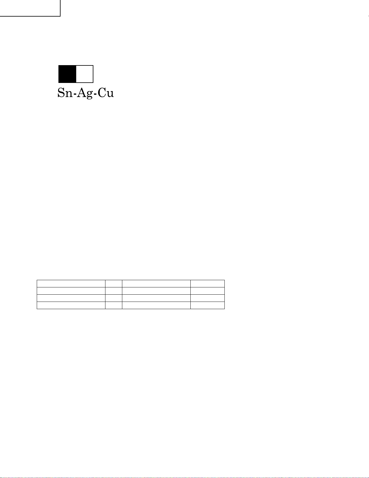
Precautions for using lead-free solder
1 Employing lead-free solder
"PWBs" of this model employs lead-free solder. The LF symbol indicates lead-free solder, and is attached on the
PWBs and service manuals. The alphabetical character following LF shows the type of lead-free solder.
Example:
L Fa
Indicates lead-free solder of tin, silver and copper.
2 Using lead-free wire solder
When fixing the PWB soldered with the lead-free solder, apply lead-free wire solder. Repairing with conventional
lead wire solder may cause damage or accident due to cracks.
As the melting point of lead-free solder (Sn-Ag-Cu) is higher than the lead wire solder by 40°C, we recommend
you to use a dedicated soldering bit, if you are not familiar with ho w to obtain lead-free wire solder or soldering bit,
contact our service station or service branch in your area.
3 Soldering
As the melting point of lead-free solder (Sn-Ag-Cu) is about 220°C which is higher than the conventional lead
solder by 40°C, and as it has poor solder wettability, you may be apt to keep the soldering bit in contact with the
PWB for extended period of time. However, since the land may be peeled off or the maximum heat-resistance
temperature of parts may be exceeded, remov e the bit from the PWB as soon as y ou confirm the steady soldering
condition.
Lead-free solder contains more tin, and the end of the soldering bit may be easily corroded. Make sure to turn on
and off the power of the bit as required.
If a different type of solder stays on the tip of the soldering bit, it is allo y ed with lead-free solder. Clean the bit after
every use of it.
When the tip of the soldering bit is blackened during use, file it with steel wool or fine sandpaper.
Be careful when replacing parts with polarity indication on the PWB silk.
Lead-free wire solder for servicing
Part No, ★ Description Code
ZHNDAi123250E J φ0.3mm 250g(1roll) BL
ZHNDAi126500E J φ0.6mm 500g(1roll) BK
ZHNDAi12801KE J φ1.0mm 1kg(1roll) BM
6
Page 7
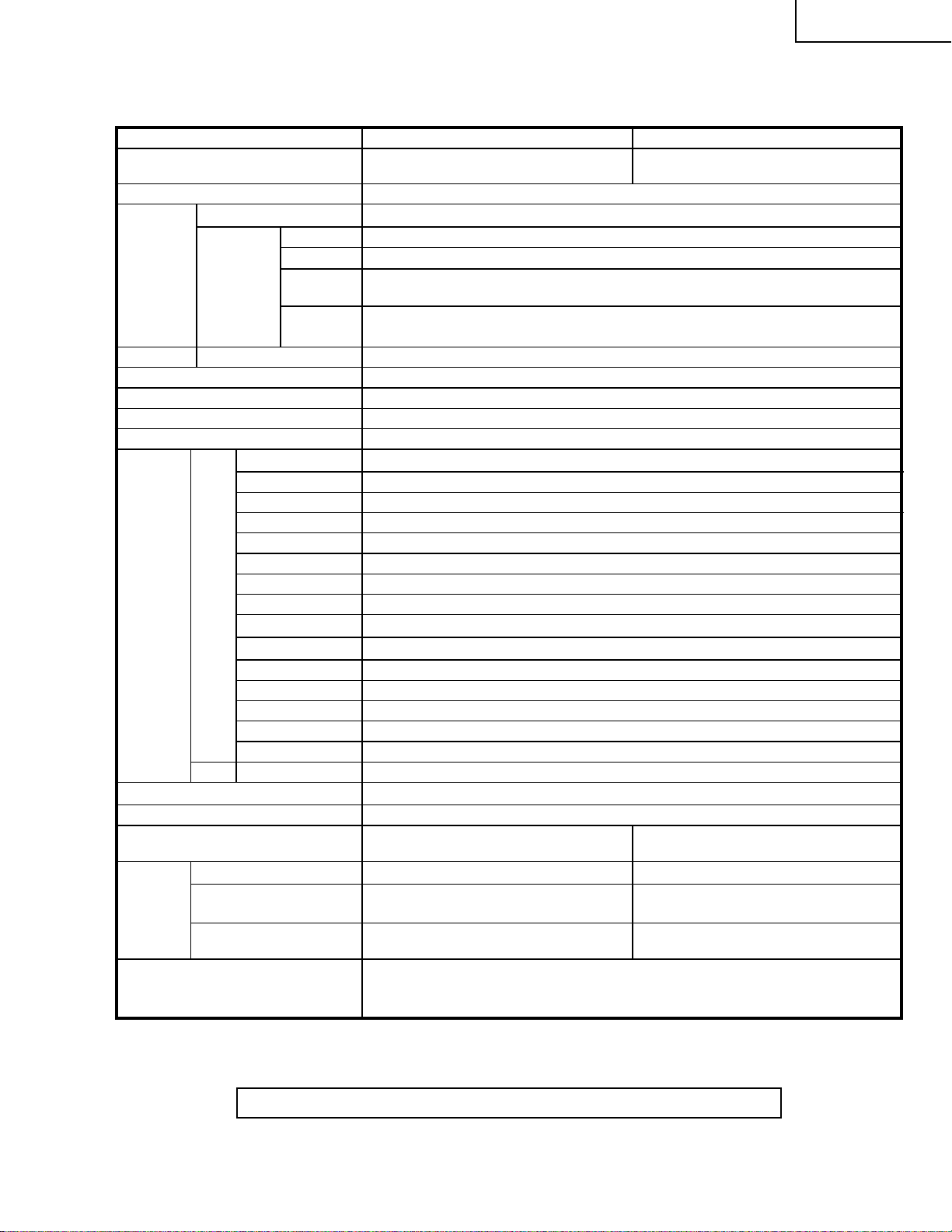
SPECIFICATIONS
LC-32GD6U
LC-37GD6U
Item
LCD panel
Number of dots 3,147,264 dots (1366 × 768 × 3 dots)
TV
Function
Brightness 450 cd/m
Viewing angles H : 170° V : 170°
Audio amplifier 10W × 2
Speakers Ø 8cm 2pcs, Ø 2.5cm 2pcs
Terminals
OSD language
Power Requirement
Power Consumption
Weight
Accessories Operation manual (×1), Remote control unit ( × 1), AC cord ( ×1), “AAA” size
TV-standard (CCIR)
Receiving
Channel
Audio multiplex BTSC System
Rear
Front
INPUT 1
INPUT 2
INPUT 3
INPUT 4
INPUT 5 Audio in, DVI-I in with HDCP
ANALOG ANTENNA
DIGITAL ANTENNA
MONITOR OUTPUT
EXTERNAL SPEAKER
CENTER CHANNEL INPUT
DIGITAL AUDIO OUTPUT
i.LINK
PC CARD slot
CableCARD slot
DC OUTPUT
Headphones Ø 3.5mm jack
Display only
with Display and
speaker
with Display, speaker
and stand
VHF/UHF
CATV
Digital Terrestrial
Broadcast (8VSB)
Digital cable
(64/256 QAM)
American TV Standard ATSC/NTSC System
VHF 2-13ch, UHF 14-69ch
1-125ch
2-69ch
1-135ch
AV in, COMPONENT in
AV in, COMPONENT in
S-VIDEO in, A V in
HDMI in (Type-A) with HDCP
75 Ω Unbalance, F Type for VHF/UHF/CATV in × 2, out × 1
75 Ω Unbalance, F Type for Digital Air/Cable in × 1
S-VIDEO out, AV out
4 Ω 10W (L/R)
RCA pin
Optical Digital audio output × 1 (PCM/Dolby Digital)
IEEE1394 × 2 with DTCP
68 pin PCMCIA × 1
68 pin PCMCIA × 1
DC 9 V 7 W MAX
English/French/Spanish
AC 120 V, 60 Hz
182 W (10 W Standby
with AC 120 V)
36.4 lbs./16.5 kg
44.5 lbs./20.2 kg
54.5 lbs./24.7 kg
battery ( × 2), Cable clamp ( × 1), RF cable ( × 1)
Model: LC-32GD6U Model: LC-37GD6U
32" Advanced Super
View & BLACK TFT LCD
2
37" Advanced Super
View & BLACK TFT LCD
224 W (10 W Standby
with AC 120 V)
40.8 lbs./18.5 kg
49.2 lbs./22.3 kg
59.1 lbs./26.8 kg
• As part of policy of continuous improvement, SHARP reserves the right to make design and specification changes for pr oduct improvement
without prior notice. The performance specification figures indicated are nominal values of production units. There may be some
deviations from these values in individual units.
Specifications are subject to change without prior notice.
7
Page 8
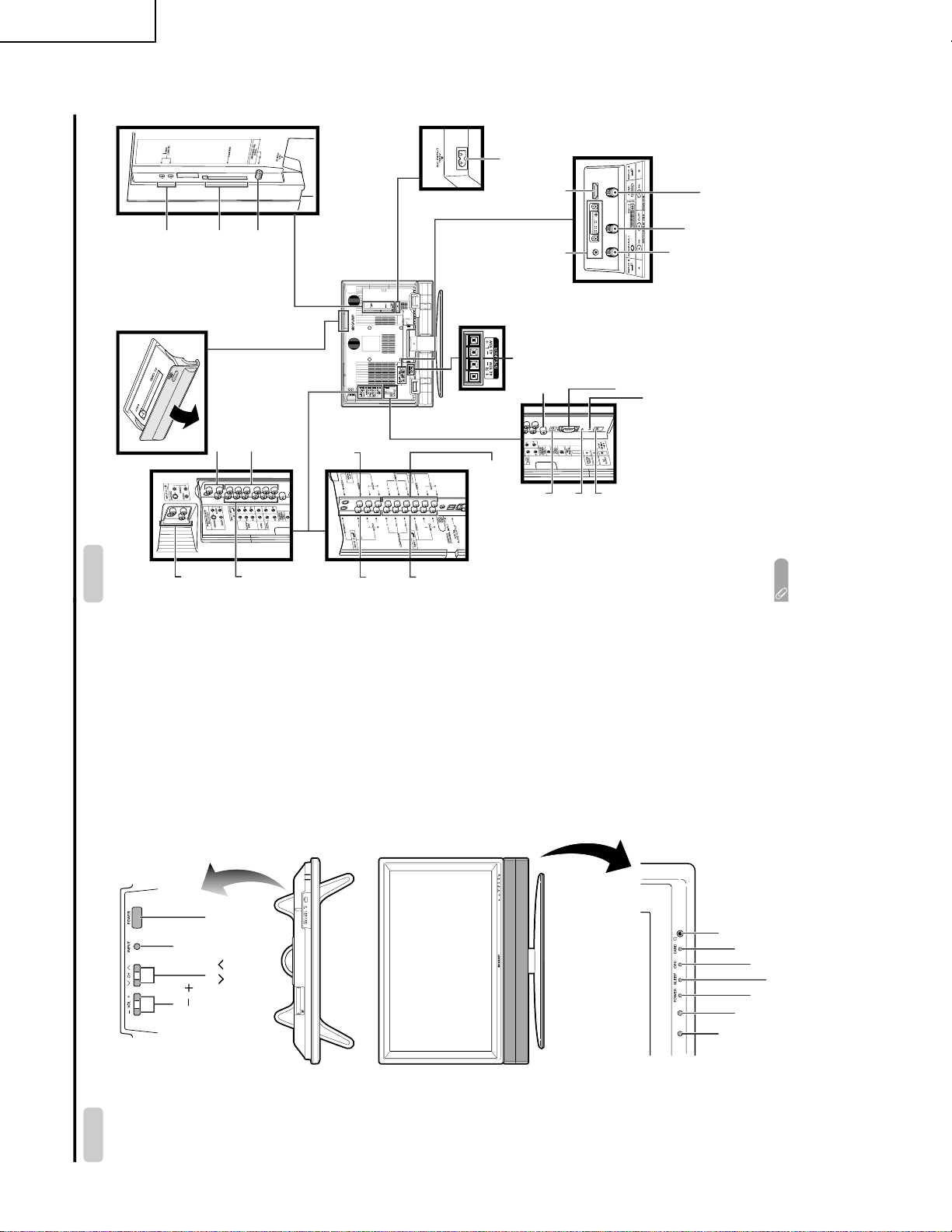
LC-32GD6U
Part names
POWER indicator
OPC sensor
Display
POWER
button
INPUT
button
VOLUME buttons
(VOL / )
CHANNEL buttons
(CH / )
Remote control sensor
*OPC: Optical Picture Control
(See page 33.)
SLEEP indicator
OPC indicator
Headphone jack
CARD indicator
LC-37GD6U
LC-32GD6U
LC-26GD6U
Display
* Press RESET if the system cannot return to its
original state after performing various operations.
• AV MODE resets to DYNAMIC (Fixed)
• TV channel returns to initial channel (Air:2ch, Cable:1 or 2ch)
• Twin picture resets to normal
• Audio setting initializes
• Dolby virtual resets to off
• Image position initializes
**Press SYSTEM RESET if the system does not operate after starting up.
NOTE
• Pressing RESET will not work if the System is in standby mode.
• Pressing RESET will not delete channel preset or secret number. See page 66 for clearing the secret number when you
know it. See page 100 for initializing to the factory preset values when you forget your secret number.
RESET*
INPUT 3
terminals
SYSTEM RESET**
ANALOG A IN terminal
ANALOG B IN terminal
ANALOG A OUT terminal
DC OUTPUT
terminal
(Terminal for expanded
functionality in the near
future.)
EXTERNAL SPEAKER terminals
AC INPUT
terminal
RS-232C
terminal
INPUT 2 terminals
INPUT 1
terminals
INPUT 5 terminals INPUT 4 terminal
DIGITAL AUDIO OUTPUT
terminal
CENTER CHANNEL
INPUT terminal
MONITOR OUTPUT
terminals
i.LINK terminals
CableCARD slot
DIGITAL IN terminal
* This terminal
looks different on
the LC-26GD6U.
INPUT 3
terminals
INPUT 1
terminals
MONITOR
OUTPUT
terminals
INPUT 2 terminals
LC-37GD6U
OPERATION MANUAL
8
Page 9
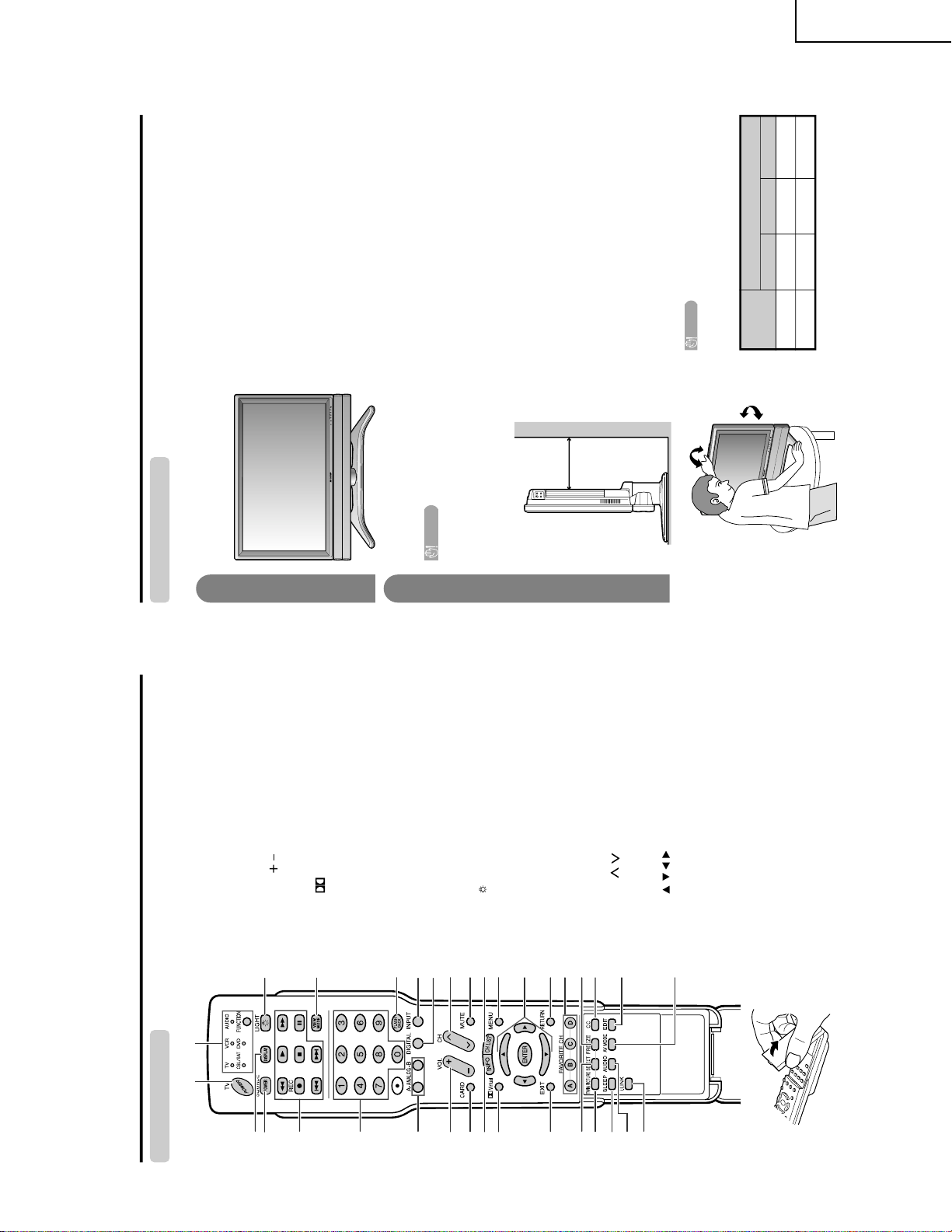
Part names
Remote control unit
3
2
117
5
6
4
7
20
18
19
21
22
23
824
925
10 26
11 28
29
30
13
14
15
12
31
16
33
27
32
1TV POWER: Switches the Liquid Crystal Television
power on or Standby. (See page 20.)
2 DISPLAY: Displays the channel information.
3 SOURCE POWER: Turns the power of the external
equipment on and off.
4 External equipment operational buttons: Operates
the external equipment.
50 – 9: Sets the channel.
6 A-ANALOG-B: Each button selects the corresponding
antenna.
7VOL /: Sets the volume. (See page 23.)
8 CARD: Switches to card mode.
9 INFO: Displays the program information screen. (See
page 85.)
10
Virtual: Select Virtual Dolby Surround settings. (See
page 23.)
11 EXIT: Turns off the menu screen.
12 SELECT: Selects the active screen. (See page 86.)
13 TWIN PICTURE: Sets the twin picture mode.
Press again to return to normal screen. (See page
86.)
14 SLEEP: Sets the sleep timer. (See page 71.)
15 AUDIO: Selects the MTS/SAP or the audio mode during
malti audio broadcasts. (See page 24.)
16 i.LINK: Displays the i.LINK panel. (See page 58.)
17 FUNCTION: Switches the remote control for TV, CBL/
SAT, VCR, DVD and AUDIO operation. Indicator lights
up for the current mode. (See page 87 to 91 for details.)
18
: When pressed all buttons on the remote control unit
will light. The lighting will turn off if no operations are
performed within about 5 seconds. This button is used
for performing operations in dark places.
19 VIEW MODE: Selects the screen size. (See pages 68
and 69.)
20 FLASHBACK: Returns to the previous channel or input
external mode. (See page 22.)
21 INPUT: Selects a Liquid Crystal Television input source.
(TV, INPUT 1, INPUT 2, INPUT 3, INPUT 4, INPUT 5,
i.LINK, Card) (See pages 50 and 66.)
22 DIGITAL: Receives digital broadcasts.
23 CH / : Selects the channel.
24 MUTE: Mutes the sound. (See page 23.)
25 CH LIST: Displays the channel list screen.
26 MENU: Displays the menu screen.
27 ///: Selects a desired item on the screen.
28 RETURN: Returns to the previous menu screen.
29 FAVORITE CH
A, B, C, D: Selects four preset favorite channels in four
different categories. (See page 31 for details.)
While watching, you can toggle the selected channels
by pressing A, B, C and D.
30 FREEZE: Sets the still image. Press again to return to
normal screen. (See page 86.)
31 CC: Displays captions during closed-caption source.
(See page 73.)
32 EDIT: Registers favorite channel.
33 AV MODE: Selects an audio or video setting. (See
page 68.) (AV mode: STANDARD, MOVIE, GAME,
USER, DYNAMIC (Fixed), DYNAMIC. PC mode:
STANDARD, USER.)
Setting the TV in place
Handling the Display
CAUTION
• Do not remove the stand and speaker from the Display unless
using an optional bracket to mount it.
• Keep enough space above and behind the Display.
• When you move TV, carry out by two people or more than it.
• When you move the Display, hold the portion of the Display, not the
speaker.
Where to place the TV
First select the location where to place the TV.
Selecting the location of the TV
• Select a place with good ventilation.
Display
1
2
4 inches
(10 cm)
or more
Preparation
CAUTION
Adjust the screen with both hands. Put one
hand on the Display and tilt the screen while
steadying the stand with your other hand.
LC-37GD6U
Maximum Degree of Adjustment
Up
Down Left/Right
6˚ 2˚ 10˚ each
LC-32GD6U 6˚ 2˚ 10˚ each
LC-32GD6U
LC-37GD6U
9
Page 10
LC-32GD6U
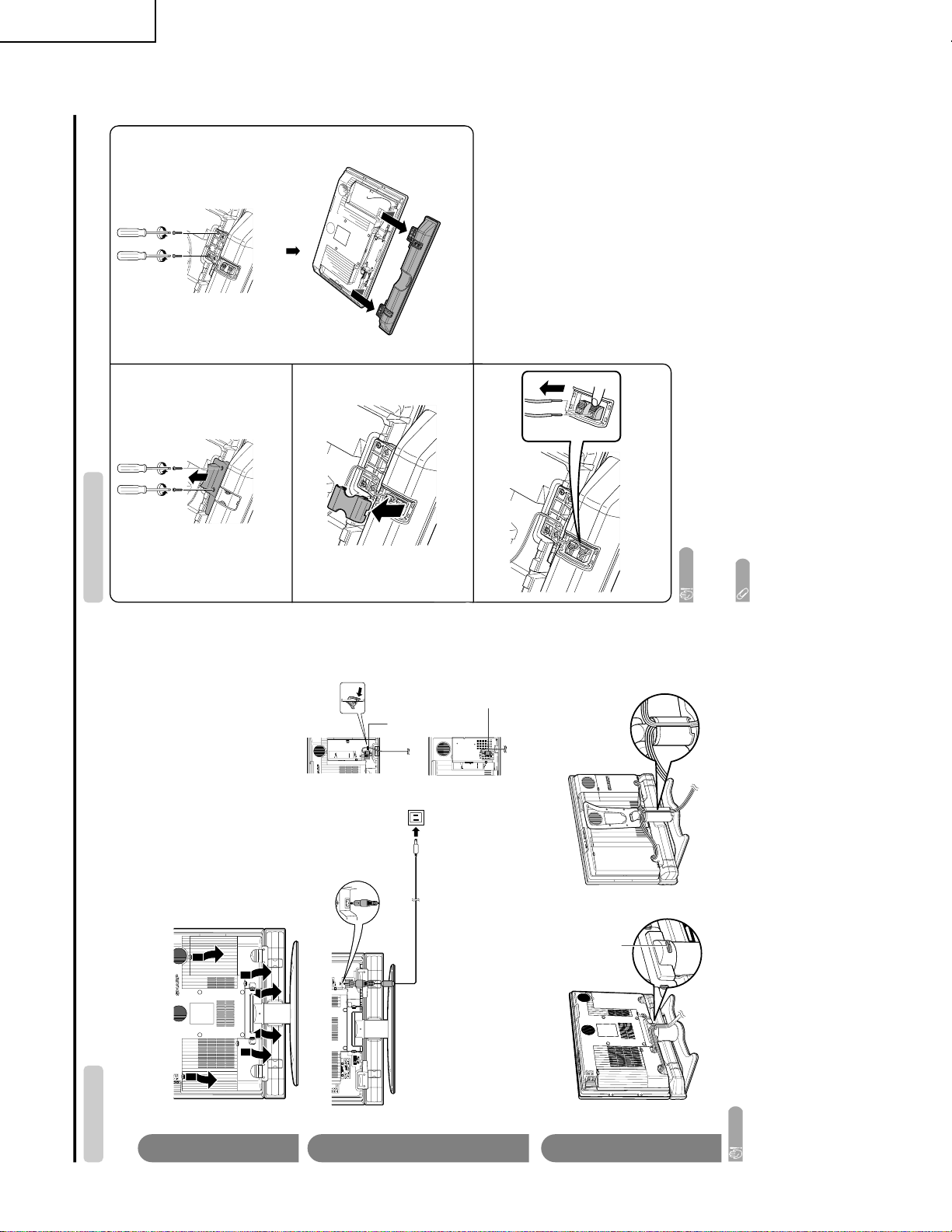
Preparation
Display (rear view)
Setting the TV
After putting the Display in place, connect the AC cord. Use the cable clamp for bundling the cables.
Connecting the AC cord to the Display
1
2
3
Removing the terminal cover
Bundling the cables with the clamp
CAUTION
• TO PREVENT RISK OF ELECTRIC SHOCK, DO NOT TOUCH UN-INSULATED PARTS OF ANY CABLES WITH THE
AC CORD CONNECTED.
Press down the hooks
to remove the cover
toward you.
AC cord (with
Ferrite core)
for LC-37GD6U/LC-32GD6U
Cable clamp
for LC-26GD6U
Put the Ferrite core in the space as shown in the
figure. If the AC cord is not put in properly, the
terminal cover may not close.
for LC-26GD6U
for LC-32GD6U
Ferrite core
Ferrite
core
Removing speakers
NOTE
• To attach the speakers, perform the steps in reverse order.
CAUTION
• Do not remove the stand and speaker from the Display unless using an optional bracket to mount it.
• Before performing work spread cushioning over the base area to lay the Display on. This will prevent it from
being damaged.
1
2
3
4
Unfasten the screw used to secure the speaker
bracket.
Unfasten the screws.
Take off the speaker terminal cover.
Disconnect the cable from the speaker.
The illustration shows the LC-37GD6U/LC-32GD6U.
LC-37GD6U
10
Page 11
LC-32GD6U
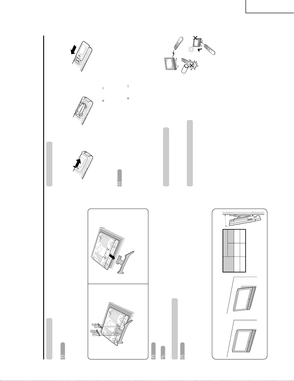
Preparation
Removing the stand
Before detaching (or attaching) stand, unplug the AC cor d from the AC input ter minal.
CAUTION
• Do not remove the stand from the Display unless using an optional wall mount bracket to mount it.
Before attaching/detaching stand
•Before perfor ming work make sur e to tur n off the TV .
•Before perfor ming work spr ead cushioning over the base ar ea to lay the Display on. This will pr event it fr om
being damaged.
NOTE
• To attach the stand, per form the above steps in r everse or der.
2
Detach the stand fr om the Display .
(Hold the stand so it will not dr op from the edge of
the base area.)
1
Unfasten the four scr ews used to secur e the
stand in place.
Setting the Display on the wall
CAUTION
• Installing the Liquid Crystal Television requires special skill that should only be performed by qualified service
personnel. Customers should not attempt to do the work themselves. SHARP bear s no responsibility for improper
mounting or mounting that results in accident or injury.
Using an optional bracket to mount the Display
•You can ask a qualified service personnel about using an optional AN-37AG2 or AN-LCGWF bracket to
mount the Display to the wall. The AN-37AGZ is compatible with the LC-37GD6U and LC-32GD6U only .
•Carefully r ead the instructions that come with the bracket befor e beginning work.
Hanging on the wall
AN-37AG2 wall mount bracket. (See the bracket instructions
for details.)
About setting the Display angle
LC-37GD6U/LC-32GD6U
CAUTION
•Do not r emove the stand and speaker fr om the Display unless using an optional bracket to mount it.
Vertical mounting Angular mounting
Angle of Display
LC-37GD6U
With Speakers
Removed
With Speakers
Attached
10˚ 5˚
LC-32GD6U 20˚ 10˚
1
Open the batter y cover .
2
Inser t two “AAA” size batteries
(supplied with the pr oduct).
• Place the batteries with their ter minals
corr esponding to the ( ) and ( )
indications in the battery compartment.
3
Close the battery cover.
CAUTION
Improper use of batteries can result in chemical leakage or explosion. Be sure to follow the instructions below.
• Place the batteries with their terminals corresponding to the ( ) and ( ) indications.
• Do not mix batteries of different types. Different types of batteries have different characteristics.
• Do not mix old and new batteries. Mixing old and new batteries can shorten the life of new batteries or cause
chemical leakage in old batteries.
• Remove batteries as soon as they are worn out. Chemicals that leak from batteries can cause a rash. If you
find any chemical leakage, wipe thoroughly with a cloth.
• The batteries supplied with this product may have a shorter life expectancy due to storage conditions.
• If you will not be using the remote control unit for an extended period of time, remove batteries from it.
Inserting the batteries
If the remote control fails to operate Liquid Crystal Television functions, replace the batteries in the remote
control unit.
Using the remote control unit
Use the remote control unit by pointing it towards the remote control sensor on
the Display. Objects between the remote control unit and the remote control
sensor may prevent proper operation.
Cautions regarding remote control unit
• Do not expose the remote control unit to shock.
In addition, do not expose the remote control unit to liquids, and do not place
in an area with high humidity.
• Do not install or place the remote control unit under direct sunlight.
The heat may cause deformation of the remote control unit.
• The remote control unit may not work properly if the r emote control sensor on
the Display is under direct sunlight or strong lighting. In such cases, change
the angle of the lighting or the Display, or operate the remote control unit
closer to the remote control sensor.
LC-37GD6U
11
Page 12

LC-32GD6U
Appendix
RS-232C port specifications
Return codeCommand 4-digits Parameter 4-digits
PC Control of the TV
• When a program is set, the Display can be controlled from the PC using the RS-232C terminal.
The input signal (PC/AV) can be selected, the volume can be adjusted and various other adjustments and
settings can be made, enabling automatic programmed playing.
•
Attach an RS-232C cable cross-type (commercially available) to the supplied Din/D-Sub RS-232C for the
connections.
NOTE
• This operation system should be used by a person who is accustomed to using computers.
Communication conditions
Set the RS-232C communications settings on the PC to match the display’s communications conditions.
The Display’s communications settings are as follows:
Baud rate:
Parity bit:
Data length:
Stop bit:
Flow control:
9,600 bps
8 bits
None
1 bit
None
Command format
Communication procedure
Send the control commands from the PC via the RS-232C connector.
The display operates according to the received command and sends a response message to the PC.
Do not send multiple commands at the same time. Wait until the PC receives the OK response before sending
the next command.
Eight ASCII codes + CR
Command 4-digits:Command. The text of four characters.
Parameter 4-digits:Parameter 0 – 9, x, blank, ?
Parameter
Input the parameter values, aligning left, and fill with blank(s) for the remainder. (Be sure that 4 values are input for the
parameter.)
When the input parameter is not within an adjustable range, “ERR” returns. (Refer to “Response code format”.)
Any numerical value can replace the “x” on the table.
When “?” is input for some commands, the present setting value responds.
C1 C2 C3 C4 P1 P2 P3 P4
0055
100
−
30
0009
0
????
?
Command table
• Commands not indicated here are not guaranteed to operate.
Return code (0DH)
Response code format
Normal response
Problem response (communication error or incorrect command)
Return code (0DH)
OK
ERR
CONTROL ITEM COMMAND
PARAMETER
CONTROL CONTENTS
POWER SETTING It shifts to standby.
It input-switches by the toggle. (It is the same as an input change key)
It input-switches to TV. (A channel remains as it is. (Last memory))
It input-switches to INPUT1~INPUT5.
It input-switches to i.LINK.
It shifts to CARD mode.
An input change is also included.
Although it can choose now, it is toggle operation in inside.
Although it can choose now, it is toggle operation in inside.
(Toggle)
Input terminal number (1–5)
AUTO
VIDEO
COMPONENT
DIGITAL PC
ANALOG PC
DIGITAL AV
ANALOG AV
(Toggle)
STANDARD
MOVIE
USER
GAME
DYNAMIC (Fixed)
DYNAMIC
Volume (0–60)
AV mode. ( 10)
PC mode. (0–180)
AV mode. ( 20)
PC mode. (0–100)
Only PC mode. (0–180)
Only PC mode. (0–40)
(Toggle) [AV]
An input change is included if it is not TV display.
In Air, 2–69ch is effective.
In Cable, 1–125ch is effective.
If it is not TV display, it will input-switch to TV. same function as CH
If it is not TV display, it will input-switch to TV. same function as CH
Toggle operation of a closed caption.
(Toggle)
Side Bar [AV]
S.Stretch [AV]
Zoom [AV]
Stretch [AV]
Normal [PC]
Zoom [PC]
Stretch [PC]
Dot by Dot [PC]
On
Off
OFF
OFF TIMER – 30 MIN.
The channel number of TV
The channel number of TV 1
The channel number of TV 1
(Toggle)
(1–125)
AUTO
POWR
ITGD
ITVD
IAVD
ICRD
INP1
INP5
INPUT SELECTION A TOGGLE
i.LINK
INPUT SELECTION B
AV MODE SELECTION
VOLUME
POSITION
VIEWMODE
Dolby Virtual
SLEEP TIMER
CHANNEL
ANTENNA SELECT
CC
DIRECT
(ANALOG)
(DIGITAL)
CH UP
CH DOWN
CHANNEL
H-POSITIONH-POSITION
V-POSITION
CLOCK
PHASE
INPUT 1
INPUT 5
AVMD
VOLM
HPOS
VPOS
CLCK
PHSE
ACDV
OFTM
DCCH
CHUP
CHDW
CLCP
WIDE
0
x
0
*
x
0
5
6
7
8
1
2
0
*
*
*
*
*
0
0
*
x
x
x
1
1
2
0
1
2
3
4
5
6
7
8
*
*
1
2
3
4
5
6
*
_
_
_
_
_
_
_
_
_
_
_
_
_
_
_
_
_
*
*
*
*
*
*
*
_
_
_
_
_
_
_
_
_
_
_
_
_
_
_
_
_
_
_
*
_
_
_
_
_
_
_
_
_
_
_
_
_
_
_
_
_
*
*
*
*
*
*
_
_
_
_
_
_
_
_
_
_
_
_
_
_
_
_
_
_
_
_
_
DIGITAL Air (Two-Part numbers, 2-digit plus 2-digit)(0100-9999)
(1-999)
(0-999)
(0-9999)
(0-6383)
DIGITAL Cable (Two-Part numbers, 3-digit plus 3-digit)
DIGITAL Cable (Two-Part numbers, 3-digit plus 3-digit)
Front half of DIGITAL CABLE CHANNEL NO. (Designate major channel)
Rear half of DIGITAL CABLE CHANNEL NO. (Designate minor channel)
DIRECT
CHANNEL
DA2P* * **
DC2U * * *_
DC2 L * * * _
DIGITAL Cable (One-Part numbers, 5-digit, less than 10,000)
DC1 0 * * * *
DIGITAL Cable (One-Part numbers, 5-digit, more than 10,000)
DC1 1 * * * *
_
_
ANALOG-A ANALOG-B DIGITAL(Toggle)ANTS 0 __ _
ANALOG-A1___
ANALOG-B2___
DIGITAL3___
_
_
(Toggle)
AUDIO SELECTION
ACHAx _ __
_
_
OFF TIMER – 60 MIN.
OFF TIMER – 90 MIN.
2
3
_
_
_
_
_
_
OFF TIMER – 120 MIN. 4___
_
_
(Toggle)
On
Off
MUTE
MUT E 0
1
2
_
_
_
_
_
_
_
_
_
_
_
_
_
_
_
_
_
_
_
INPUT5: AV mode. ( 90)***_
_
_
_
_
INPUT5: AV mode. ( 50)
***
_
_
_
_
_
_
_
LINKx___
_
_
_
_
_
_
_
_
AUTO
VIDEO
COMPONENT
AUTOINP2
INPUT 2
0
1
2
_
_
_
_
_
_
_
_
_
_
_
_
_
_
_
_
TV
INPUT1-5
CARD
NOTE
• If an underbar (_) appears in the parameter column, enter a space.
• If an asterisk (*) appears, enter a value in the range indicated in brackets under CONTROL CONTENTS.
• As long as that from which the parameter ( ) in the table is a numerical value, it may write anything.
LC-37GD6U
12
Page 13

LC-32GD6U
Basic adjustment settings
AV input mode menu items
List of AV menu items to help you with
operations
OPC
Backlight
Contrast
Brightness
Color
Tint
Sharpness
Advanced
C.M.S.
Color Temp.
Black
3D-Y/C
Monochrome
Film Mode
I/P Setting
Picture
No Signal Off
No Operation Off
EZ Setup
CH Setup
Antenna Setup-DIGITAL
Speaker Setup
Input Label
Parental CTRL
Position
Picture Flip
Language
Treble
Bass
Balance
Dolby Virtual
Audio Only
Digital Noise Reduction
HDMI Setup
Input Select
Output Select
Quick Shoot
Center Channel Input
Caption Setup
Title Display Type
Audio
Power Control
Setup
Option
CableCARD Menu
Video Setup
Audio Setup
i.LINK Setup
Digital Setup
Power Management
Speaker Setup
Input Signal
Auto Sync.
Input Label
Fine Sync.
Picture Flip
Language
Power Control
Setup
Option
Audio Only
Input Select
Output Select
Quick Shoot
Center Channel Input
i.LINK Setup
Digital Setup
*PC input mode menu items
List of PC menu items to help you with
operations
*When INPUT5 is set to PC.
OPC
Backlight
Contrast
Brightness
Red
Green
Blue
Advanced
C.M.S.
Picture
Treble
Bass
Balance
Dolby Virtual
Audio
LC-37GD6U
13
Page 14

LC-32GD6U
LC-37GD6U
16
/
15
3
(100)
(480)
8
/
7
(577)
18
(638)
32
/
64
/
23
7
22
25
LC-32GD6U
2641/64 (677)
319/32 (795)
279/16 (700.4)
(395.1)
64
/
35
15
DIMENSIONS
Unit: inch/(mm)
4 (102)
433/64 (116)
(400)
64
/
47
15
755/64 (200)
(61.5)
32
/
13
2
(200)
64
/
55
7
(400)
64
/
47
15
125/64 (307)
16
/
15
3
(100)
LC-37GD6U
Unit: inch/(mm)
4 (102)
2641/64 (677)
363/32 (917)
433/64 (116)
323/8 (822.6)
(548)
16
/
9
(645)
21
8
/
3
(706)
32
/
25
(463.8)
4
/
1
(434)
64
/
5
17
18
25
27
755/64 (200)
64
/
49
3
(95.9)
(200)
64
/
55
7
(434)
64
/
5
17
125/64 (307)
14
Page 15

REMOVING OF MAJOR PARTS
1. Remove the Terminal Covers 1 .
2. Remove 4 lock screws 2 and detach the Stand.
3. Remove 4 lock screws 3 and detach the Bracket Covers.
4. Remove 4 lock screws 4 and separate the Speaker Box from the set.
Disconnect SP wire (R) and SP wire (L).
5. Remove 26 lock screws 5 from Rear Cabinet, and detach the Rear Cabinet.
Rear Cabinet
1
Terminal
Cover (L)
SP wire (L)
SP Bracket
4
Bracket Cover
3
2
5
5
5
SP Bracket
3
Bracket Cover
4
5
1
SP wire (R)
Speaker Box
Terminal
Cover
(Center)
LC-32GD6U
LC-37GD6U
Front Cabinet
1
Terminal
Cover (R)
6. Remove 1 Center frame fixing screw 6.
Stand
7. Remove 7 center frame fixing screws 7.
8. Remove the connector 8 from the LCD Controller Unit, and then detach the center frame.
9. Remove 2 screws for fixing the top control cover ass'y 9, and
then detach the connector 0 of the LCD Controller Unit.
10. Remove 2 lock screws q from the Key PWB, and detach the Key PWB.
11. Remove 2 main shield cover fixing screws w.
12. Remove the FFC e connecting the Main Unit and AV PWB.
13. Remove 2 lock screws r from AV Terminal Cover (Bottom) and
detach the AV Terminal Cover (Bottom).
14. Disconnect all the connectors from all the PWBs.
Top Control
Cover Ass’y
10
Connector
9
11
Key
PWB
13
Connector
8
LCD
Controller
Unit
8
10
FFC
13
13
7
6
7
Center Frame
15
14
AV Terminal Cover (Bottom)
Main Shield Cover
12
Page 16

LC-32GD6U
16
15
17
19
Main PWB Angle
Cover
Digital Tuner Unit
Main Unit
DVI PWB Angle
DVI PWB
Fan holder
[FB]
[RA]
[SP]
[VD]
20
Shield
PC Card Unit
[FP]
18
18
18
Main PWB Shield (Top)
18
21
26
LC-37GD6U
15. Remove 4 screws for fixing the DVI PWB ass'y t to detach the Ass'y.
16. Remove 4 screws for fixing the DVI PWB angle y to detach the angle.
17. Remove the FP, FB, VD, RA and SP connectors.
18. Remove 6 screws for fixing the
Main PWB Angle u to detach
the angle and Shield.
19. Remove 15 screws for fixing the
Main PWB shield (top) i to
detach the shield.
20. Remove the Main Unit and
digital tuner unit.
21. Remove 2 cover fixing screws
o to detach the cover.
22. Remove 3 fan angle fixing
screws p to detach the fan
angle.
23. Remove 1 screw and 3 FFC
fixing tapes a to detach the
PC Card PWB.
16
Page 17

24. Remove the RM, ST, PA, SA, SC, GV, PG, PG1, PG2, PO and BL connectors.
25. Remove 2 FPC s connecting the LCD panel and LCD controller unit.
26. Remove 18 connectors d from the lamps. (LC-32GD6U)
Remove 16 connectors d from the lamps. (LC-37GD6U)
22
[ST]
LC-32GD6U
LC-37GD6U
[BL]
[RM]
[GV]
[SC] [SA]
[PG]
[PO]
[PA]
[PG1]
[PG2]
2323
27. Remove 4 AV PWB fixing screws f to detach the AV PWB. Remove 5 terminal fixing screws (g: 2
pcs., h : 3 pcs.) to detach the AV PWB holder from the AV PWB.
28. Remove 2 screw for fixing the external terminal PWB j to detach the external terminal PWB.
Remove 1 screw for fixing external terminal PWB holder k to detach the external terminal PWB holder
from the external terminal PWB.
29. Remove 6 screws for fixing the LCD controller PWB l to detach the LCD controller PWB.
30. Remove 2 screws for fixing the R/C LED PWB ; to detach the R/C LED PWB.
31. Remove 2 EXT SP terminal unit fixing screws 31 to detach the EXT SP terminal unit.
32. Remove 2 screws for fixing the 1-Bit Amp PWB 32 to detach the 1-Bit Amp PWB.
33. Remove 6 screws for fixing the Power Supply PWB 33 to detach the Power Supply PWB.
34. Remove 4 screws for fixing the Inverter A PWB 34 to detach the inverter A PWB.
35. Remove 4 screws for fixing the Inverter B PWB 35 to detach the inverter B PWB.
36. Remove 4 screws for fixing the Inverter GND-A PWB 36 to detach the inverter GND-A PWB.
37. Remove 4 screws for fixing the Inverter GND-B PWB 37 to detach the inverter GND-B PWB.
24
LC-32GD6U
25
26
AV PWB Holder
External T erminal PWB
36
Inverter GND-1A PWB
37
Inverter GND-2B PWB
LC-37GD6U
R/C LED PWB
27
30
EXT SP TERMINAL
PWB
28
31
AV PWB
1-Bit Amp PWB
LCD Controller PWB
29
32
33
34
Inverter-1A PWB
35
Inverter-2B PWB
LC-37GD6U
Power Supply PWB
LC-32GD6U
17
Page 18

LC-32GD6U
LC-37GD6U
38. Remove 4 screws for fixing the LCD Panel Unit 38 to detach the LCD Panel Unit from the Cabinet A.
38
LCD Panel Unit
18
Page 19

REMO VING OF LCD PANEL UNIT (LC-32GD6U)
39. Remove 5 screws for fixing the LCD Panel Unit 38 .
40. Remove 14 screws for fixing the sheet angle
41. Remove the Reflection/Deflection Sheet, Prism Sheet, Diffusion Sheet, and Diffusion Board.
42. Remove 6 screws for fixing the Lamp Holder (upper)
43. Remove the Lamps.
39
to detach the upper, lower, left, and right sheet angles.
40
to detach the Lamp Holder (upper).
Lamp Holder (upper)
(LHLDZA310WJKZ)
Backlight Chassis
LC-32GD6U
LC-37GD6U
Sheet Angle (upper)
(CANGKA221WJ01)
Sheet Angle (right)
(CANGKA222WJ01)
38
LCD Panel Unit
39
39
39
39
Sheet Angle (left)
(CANGKA222WJ01)
Sheet Angle (lower)
(CANGKA241WJ01)
40
Diffusion Board
(PCOVUA027WJZZ)
Diffusion Sheet
(PSHEPA169WJZZ)
Prism Sheet
(PSHEPA168WJZZ)
Reflection/Deflection Sheet
(PSHEPA237WJZZ)
Lamp Holder (upper)
(LHLDZA310WJKZ)
Lamp
(KLMP-A040WJZZ)
19
Page 20

LC-32GD6U
LC-37GD6U
REMO VING OF LCD PANEL UNIT (LC-37GD6U)
39. Remove 5 screws for fixing the LCD Panel Unit 38 .
40. Remove 14 screws for fixing the sheet angle
41. Remove the Reflection/Deflection Sheet, Prism Sheet, Diffusion Sheet, and Diffusion Board.
42. Remove 6 screws for fixing the Lamp Holder (upper)
43. Remove the Lamps.
39
to detach the upper, lower, left, and right sheet angles.
40
to detach the Lamp Holder (upper).
Lamp Holder (upper)
(LHLDZA308WJKZ)
Backlight Chassis
Sheet Angle (upper)
(CANGKA219WJ01)
Sheet Angle (right)
(CANGKA220WJ01)
38
LCD Panel Unit
39
39
39
39
Sheet Angle (left)
(CANGKA220WJ01)
Sheet Angle (lower)
(CANGKA239WJ01)
40
Diffusion Board
(PCOVUA028WJZZ)
Diffusion Sheet
(PSHEPA172WJZZ)
Prism Sheet
(PSHEPA171WJZZ)
Reflection/Deflection Sheet
(PSHEPA238WJZZ)
Lamp Holder (upper)
(LHLDZA308WJKZ)
Lamp
(KLMP-A041WJZZ)
20
Page 21

DESCRIPTION OF SCHEMATIC DIAGRAM
VOLTAGE MEASUREMENT CONDITION:
1. When the exclusive-use AC adapter is used, the colour
bar signal of colour bar generator for service is input to
get the normal screen. When the audio is minimized,
the voltage value is measured with the 20 kΩ/V tester.
WAVEFORM MEASUREMENT CONDITION:
1. When the exclusive-use AC adapter is used, the colour
density, lightness and colour hue are set to the center
position, and the signal of colour bar generator for
service is observed to get waveform.
INDICATION OF RESISTOR & CAPACITOR:
RESISTOR
1. The unit of resistance “Ω” is omitted.
(K=kΩ=1000 Ω, M=MΩ).
2. All resistors are ± 5%, unless otherwise noted.
(J= ± 5%, F= ± 1%, D= ± 0.5%)
3. All resistors are Carbon type, unless otherwise noted.
C : Solid W : Cement
S : Oxide Film T : Special
N : Metal Coating
LC-32GD6U
LC-37GD6U
CAPACITOR
1. All capacitors are mF, unless otherwise noted.
(P=pF=mmF).
2. All capacitors are Ceramic type, unless otherwise
noted.
(ML) : Mylar (TA) : Tantalum
(PF) : Polypro Film (ST) : Styrol
CAUTION:
This circuit diagram is original one, therefore there may be a
slight difference from yours.
IMPORTANT SAFETY NOTICE:
PARTS MARKED WITH
IMPORTANT FOR MAINTAINING THE SAFETY OF
THE SET. BE SURE TO REPLACE THESE PARTS
WITH SPECIFIED ONES FOR MAINTAINING THE
SAFETY AND PERFORMANCE OF THE SET.
“å”
( )ARE
21
Page 22

LC-32GD6U
LC-37GD6U
SCHEMATIC DIAGRAM
Ë
EXT SP TERMINAL Unit
H
G
F
E
D
C
B
A
654321
22
Page 23

LC-32GD6U
LC-37GD6U
PARTS LIST
PARTS REPLACEMENT
Replacement parts which have these special safety characteristics
identified in this manual; electrical components having such features
are identified by å and shaded areas in the Replacement Parts Lists
and Schematic Diagrams. The use of a substitute replacement part
which dose no have the same safety characteristic as the factory
recommended replacement parts shown in this service manual may
create shock, fire or other hazards.
"HOW TO ORDER REPLACEMENT PARTS"
To have your order filled promptly and correctly, please furnish the
following informations.
1. MODEL NUMBER 2. REF. NO.
3. PART NO. 4. DESCRIPTION
in USA: Contact your nearest SHARP Parts Distributor to order.
For location of SHARP Parts Distributor, Please call TollFree; 1-800-BE-SHARP
★ MARK: SPARE PARTS-DELIVERY SECTION
Ref. No. Part No. ★ Description Code
LISTE DES PIECES
CHANGE DES PIECES
Les pi`eces de rechange qui pr élelesentent ces caract éleristiques
sp éleciales de s élecurit éle, sont identifi élees dans ce manuel :
lespi`eces élelectriques qui pr élesentent ces particular it éles, sont
rep éler élee par la marque ået sont hachur élees dans les listes de
pi`eces et dans les diagrammes sch élematiques.
La substitution d'une pi`ece de rechange par une autre qui ne pr
éLesente pas les m éoemes caract éLeristiques de s élecurit éle que
la pi`ece recommand élee parl'usine et dans ce manuel de service,
peut provoquer une éLelectrocution, un incendie ou toutautre sinistre.
"COMMENT COMMANDER LES PIECES DE
RECHANGE"
Pour que votre commande soit rapidement et correctement remplie,
veuillez fournir les renseignements suivants.
1. NUMERO DU MODELE 2. NO. DE REF
3. NO. DE PIECE 4. DESCRIPTION
in CANADA: Contact SHARP Electronics of Canada Limited
Phone (416) 890-2100
Ref. No. Part No. ★ Description Code
PRINTED WIRING BOARD ASSEMBLIES
(NOT REPLACEMENT ITEM)
LC-32GD6U
DUNTKC664UJ01 – AV Unit —
DUNTKC665UJ01 – KEY Unit —
DUNTKC666UJ01 – R/C LED Unit —
DUNTKC667UJ01 – EXT-SP Unit —
DUNTKC668UJ01 – FRONT Unit —
DUNTKC267VJ27 – DVI Unit —
DUNTKC268VJ23 J LCD CONTROL Unit CH
DKEYDC307VJ12 J DIGITAL Unit CV
DUNTKC544VJ03 J PC CARD Unit BY
DUNTKC641VJ03 J MAIN Unit CQ
RDENCA067WJZZ – POWER Unit —
RUNTKA069WJN1 – INVERTER-A Unit —
RUNTKA070WJN1 – INVERTER-B Unit —
RUNTKA071WJZZ – INVERTER-A-GND Unit —
RUNTKA072WJZZ – INVERTER-B-GND Unit —
B2SX4102BT J 1-Bit Amplifier Unit BL
LC-37GD6U
DUNTKC664UJ03 – AV Unit —
DUNTKC665UJ03 – KEY Unit —
DUNTKC666UJ03 – R/C LED Unit —
DUNTKC667UJ03 – EXT-SP Unit —
DUNTKC668UJ03 – FRONT Unit —
DUNTKC267VJ29 – DVI Unit —
DUNTKC268VJ25 J LCD CONTROL Unit CH
DKEYDC307VJ14 J DIGITAL Unit CV
DUNTKC544VJ03 J PC CARD Unit BY
DUNTKC641VJ05 J MAIN Unit CQ
RDENCA067WJZZ – POWER Unit —
RUNTKA080WJN1 – INVERTER-A Unit —
RUNTKA081WJN1 – INVERTER-B Unit —
RUNTKA082WJZZ – INVERTER-A-GND Unit —
RUNTKA083WJZZ – INVERTER-B-GND Unit —
B2SX4102BT J 1-Bit Amplifier Unit BL
LCD PANEL
NOTE: THE PARTS HERE SHOWN ARE SUPPLIED AS AN
ASSEMBLY BUT NOT INDEPENDENTLY.
RLCDTA028WJZZ J 32" Wide LCD Panel Unit ER
(LC-32GD6U)
(LK315T3FZA0)
RLCDTA027WJZZ J 37" Wide LCD Panel Unit FS
(LC-37GD6U)
(LK370T3FZA0)
DUNTKC268VJ23 (LC-32GD6U)
DUNTKC268VJ25 (LC-37GD6U)
LCD CONTROL UNIT
R2026 VRS-CY1JF223JY J 22k 1/16W Metal Oxide AA
DUNTKC667UJ01 (LC-32GD6U)
DUNTKC667UJ03 (LC-37GD6U)
EXT-SP UNIT
J203 QTANAA004WJZZ J Terminal, 4Pin AG
23
Page 24

LC-32GD6U
LC-37GD6U
Ref. No. Part No. ★ Description Code Ref. No. Part No. ★ Description Code
CABINET AND MECHANICAL PARTS
(LC-32GD6U)
1 CCABAA611WJ01 J Front Cabinet Ass’y BG
1-1
1-2 GCOVAA829WJSA J RC/LED Cover AG
1-3 HBDGBA037WJSA J Badge, "SHARP" AM
1-4 PSPAHA298WJZZ J Mask Spacer, x2 AC
1-5 PSPAHA407WJZZ J Mask Spacer, x2 AD
1-6 PSPAHA417WJZZ J Mask Spacer, x2 AB
2 CCABBA406WJ01 J Rear Cabinet Ass'y BN
2-1
2-2 GCOVAA784WJKA J Stand Power Cover AE
2-3 GCOVAA838WJKA J Hole Cover, x4 AE
2-4 GCOVAA755WJKA J SP Hole Cover (Side), x4 AC
2-5 GCOVAA836WJKA J SP Cover (R) AG
2-6 HiNDP5733CESB J AQUOS Label AD
2-7 HiNDPA834WJSA J Stand DC Indicator AD
2-8 HiNDPA931WJSA J Speaker Terminal Indicator AD
2-9 LANGKA236WJFW J Damper Angle AF
2-10 LHLDWA048WJKZ J Holder, x3 AB
2-11 LHLDWA055WJKZ J Holder, x2 AC
2-12 LHLDWA057WJKZ J Holder AE
2-13 LHLDWA059WJKZ J Holder AC
2-14 LHLDZ0132CEZZ J Holder, x4 AD
2-15 PCLiCA001WJKZ J Hole Cover AC
2-16 XEBS930P08000 J Screw, x5 AA
2-17 XEBS930P10000 J Screw, x2 AA
2-18 GCOVAA837WJKA J SP Cover (L) AG
2-19 GDORTA004WJKA J PC Card Cover AK
2-20 PSPAZA521WJZZ J Spacer, x2 AD
2-21 MSPRDA020WJFW J Spring AC
2-22 PDMPFA002WJZZ J Damper AG
2-23 XBPSN20P05000 J Screw, x2 AA
3 CCOVAA848WJ01 J Top Control Cover Ass’y AT
3-1
3-2 JBTN-A307WJKA J Control Button AK
3-3 JBTN-A340WJKA J Power Button AG
3-4 MSPRCA049WJFW J Power Button Spring AC
4 CCOVAA853WJ01 J Cover AQ
4-1
4-2 LHLDZA405WJZZ J Holder AE
4-3 XEBSN30P06000 J Screw, x2 AA
5 CDAi-A122WJ03 J Stand Ass’y BX
5-1 GDAi-A122WJKA J Stand Base BC
5-2 GDAi-A117WJF8 J Swivel Base AP
5-3 GDAi-A125WJSA J Stand, Support BB
5-4 LANGKA282WJSA J Base Angle BF
5-5 LX-NZA013WJFN J Nut AE
5-6 MHNG-A075WJSA J Hinge BK
5-7 PSPAZA476WJZZ J Spacer, x4 AC
5-8 PSPAZA477WJZZ J Spacer, x2 AD
5-9 XCSS940P25000 J Screw, x5 AB
5-10 XEBS940P10000 J Screw, x10 AB
5-11 XCBS940P25000 J Screw, x5 AB
5-12 PSPAZA530WJZZ J Spacer, x2 AD
6
6-1 RLCDTA028WJZZ J
6-2 CANGKA221WJ01 J
6-2-1
6-2-2 PSPAKA049WJKZ J Spacer, x1 AC
6-3 CANGKA222WJ01 J
6-3-1
6-3-2 PSPAKA042WJKZ J Spacer, x1 AC
6-3-3 PSPAKA048WJKZ J Spacer, x1 AC
Not Available
Not Available
Not Available
Not Available
Not Available
Not Available
Not Available
– Front Cabinet —
– Rear Cabinet —
– Top Control Cover —
–Cover —
–
32 WIDE LCD PANEL Unit Ass’y
32 WIDE LCD PANEL Unit
Sheet Angle Ass’y (Top), x2
– Sheet Angle, x2 —
Sheet Angle Ass’y (Side), x2
–
Sheet Angle,
x2 —
—
ER
AM
AP
6-5 CCHSMA121WJ02 J Chassis Ass’y BY
6-5-1
6-5-2 LANGFA102WJFW Fixing Metal AQ
6-5-3 LANGKA242WJFW J Fixing Metal, x2 AL
6-5-4 LANGKA274WJZZ J Fixing Metal AT
6-5-5 LANGKA288WJFW J Fixing Metal AT
6-5-7 LHLDWA041WJKZ J Wire Holder, x2 AC
6-5-8 LHLDWA043WJKZ J Wire Holder, x4 AB
6-5-9 LHLDWA046WJKZ J Wire Holder, x8 AC
6-5-10 LHLDWA055WJKZ J Wire Holder AC
6-5-11 LHLDWA056WJKZ J Wire Holder, x5 AC
6-5-12 LHLDWA058WJKZ J Wire Holder, x2 AC
6-5-13 LHLDZA316WJKZ J Lamp Clip, x8 AD
6-5-14 LHLDZA346WJKZ J Mirror Clip, x18 AC
6-5-15 LX-BZA046WJFN J Screw, x17 AA
6-5-16 LX-HZA023WJFN J Screw, x2 AB
6-5-17 PMiR-A051WJZZ J Mirror BE
6-5-18 PSPAHA338WJZZ J Spacer, x9 AB
6-5-19 PSPAHA339WJZZ J Spacer, x2 AD
6-5-20 PSPAHA397WJZZ J Spacer, x6 AB
6-5-21 PSPAHA398WJZZ J Spacer, x4 AB
6-5-22 PSPAKA043WJKZ J Spacer, x8 AB
6-5-23 PSPAZA519WJZZ J Spacer AB
6-5-24 PZETKA078WJZZ J Insulator AP
6-5-25 TCAUZA031WJZZ J Caution Label AB
6-5-26 TLABNA922WJZZ J No. Label AF
6-5-27 XBPSN30P06WS0 J Screw, x3 AA
6-6 KLMP-A040WJZZ J Lamp, x8 AZ
6-7 LHLDZA309WJK0 J Lamp Holder (Bottom), x2 AL
6-8 LHLDZA310WJKZ J Lamp Holder (Top), x2 AM
6-9 LX-BZA051WJFN J Screw, x5 AB
6-10 LX-BZA052WJFN J Screw, x4 AA
6-11 LX-BZA074WJFN J Screw, x4 AA
6-12 PCOVUA027WJZZ J Diffusion Panel BG
6-13 PSHEPA237WJZZ J
6-14 PSHEPA168WJZZ J Prism Sheet BN
6-15 PSHEPA169WJZZ J Diffusion Sheet AW
6-16 RUNTKA069WJN1 – INVERTER-A Unit —
6-17 RUNTKA070WJN1 – INVERTER-B Unit —
6-18 RUNTKA071WJZZ – INVERTER-A-GND Unit —
6-19 RUNTKA072WJZZ – INVERTER-B-GND Unit —
6-20 XBBSN30P08000 J Screw, x6 AA
6-21 XBPSL30P06WS0 J Screw, x14 AA
6-22 XEBSN30P10000 J Screw, x6 AA
7 CHLDZA383WJ01 J PC Card Flap Ass’y AQ
7-1 GCOVA2061CEKB J PC Card Flap AD
7-2
7-3 MSPRDA024WJFW J PC Card Flap Spring AB
8 CSLDMA491WJ01 J Main Shield Cover Ass’y AR
8-1
8-2 PMLT-A146WJZZ J Absorber AE
8-3 PMLT-A147WJZZ J Absorber AD
9
9-1 CPNLSA024WJ02 J Speaker Panel BX
9-2 LHLDZA372WJKA J Holder AP
9-3 LHLDZA373WJKA J Holder AP
9-4 RSP-ZA075WJN2 J Speaker BW
9-5 XBBS950P14000 J Screw, x4 AB
10 CANGKA269WJ01 J SP Angle Ass’y AQ
10-1
10-2 PSPAHA415WJZZ J Spacer, x2 AB
11 CANGFA118WJ01 J Fan Holder Ass’y AR
11-1
11-2 PSPAGA187WJ00 J Spacer, x4 AB
11-3 PSPAHA159WJZZ J Spacer, x2 AB
11-4 XBPSN30P08JS0 J Screw, x2 AB
Not Available
Not Available
Not Available
Not Available
Not Available
Not Available
– Chassis —
Reflection/Deflection Sheet
– PC Card Holder —
– Main Shield Cover —
– Speaker Ass’y —
– SP Angle —
– Fan Holder —
BW
6-4 CANGKA241WJ01 J
6-4-1
6-4-2 PSPAKA041WJKZ J Spacer, x1 AC
Not Available
Sheet Angle Ass’y (Bottom), x2
–
Sheet Angle,
x2 —
AK
12 CANGKA272WJ03 J MAIN PWB Angle Ass’y BB
12-1
12-2 LHLDWA029WJKZ J Wire Holder AC
Not Available
– MAIN PWB Angle —
24
Page 25

LC-32GD6U
LC-37GD6U
Ref. No. Part No. ★ Description Code Ref. No. Part No. ★ Description Code
CABINET AND MECHANICAL PARTS
(LC-32GD6U) (Continued)
12-3 PCLiC1033CEZZ J Clip, x2 AC
12-4 PSPANA006WJZZ J Spacer AC
12-5 PZETKA092WJZZ J Insulator AN
13 DUNTKC267VJ27 – DVI Unit —
14 DUNTKC268VJ23 J LCD CONTROL Unit CH
15 DKEYDC307VJ12 J DIGITAL Unit CV
16 DUNTKC544VJ03 J PC CARD Unit BY
17 DUNTKC641VJ03 J MAIN Unit CQ
18 DUNTKC664UJ01 – AV Unit —
19 DUNTKC665UJ01 – KEY Unit —
20 DUNTKC666UJ01 – R/C LED Unit —
21 DUNTKC667UJ01 – EXT-SP Unit —
22 DUNTKC668UJ01 – FRONT Unit —
23 RDENCA067WJZZ – POWER Unit —
24 B2SX4102BT J 1-Bit Amplifier Unit BL
25 LHLDW1072GEZZ J Wire Holder AA
26 PSLDMA419WJFW J Tuner Shield AK
27 QCNW-C398WJQZ J
28 QCNW-C402WJQZ J
29 QCNW-C411WJQZ J
30 QCNW-C510WJPZ J
31 QCNW-C617WJPZ J
32 QCNW-C860WJPZ J
33 QCNW-C861WJPZ J
34 QCNW-C862WJQZ J
35 QCNW-C394WJQZ J
36 QCNW-C399WJQZ J
37 QCNW-C412WJQZ J
38 QCNW-C413WJQZ J
39 QCNW-C437WJQZ J
40 CANGKA292WJ01 J AV PWB Angle Ass’y AT
40-1
40-2 LHLDWA043WJKZ J Holder, x4 AB
41 NSFTZ0134CEFW J DVI Shaft AD
42 PMLT-A145WJZZ J Gasket AD
43 PSLDMA422WJFW J DVI Shield AH
44 PSLDMA423WJFW J HDMI Shield AH
45 QCNW-C432WJPZ J
46 QCNW-C434WJPZ J
47 QCNW-C520WJPZ J
48 XBBS930P06000 J Screw AA
49 XBPSL30P06WS0 J Screw, x4 AA
50 GCOVAA678WJKA J SD Card Cover AE
51 GCOVAA825WJKA J Rear Cover (R) AR
52 GCOVAA826WJKA J Rear Cover (L) AS
53 GCOVAA827WJKA J Rear Cover (Center) AM
54 GCOVAA849WJKA J Terminal Cover (M) AM
55 GCOVAA852WJKA J Terminal Cover (B) AK
56 GCOVAA871WJKA J Terminal Cover (R T) AH
57 GCOVHA042WJKA J CATV Card Cover AE
58 HiNDPA933WJSA J Model Label AH
59 LANGFA099WJFW J Center Frame BL
60 LANGKA271WJZZ J Stand Angle Bracket AP
63 LANGKA297WJFW J Fixing Metal AM
64 PSPAZA517WJZZ J Spacer, x3 AD
65 PSPAZA518WJZZ J Spacer AD
66 LX-BZA046WJFN J Screw (for SP Stand), x4 AA
67 NFANR0126CEZZ J FAN, x2 AT
68 PMLT-A132WJZZ J Gasket (TUNER-DVI) AH
69 PMLT-A138WJZZ J Gasket AD
70 PMLT-A139WJZZ J Gasket AE
71 PMLT-A140WJZZ J Gasket AC
72 PMLT-A145WJZZ J iLink Gasket AD
73 PSLDMA368WJN1 J PC Card Shield AH
74 PSLDMA424WJFW J Main PWB Shield (Up) AX
75 PSLDMA530WJZZ J Shield, x2 AP
76 PSPAGA187WJ00 J Spacer, x4 AB
77 PSPAGA203WJZZ J Spacer, x2 AC
Not Available
Connecting Cord, AV-POW [PA]
Connecting Cord, AV-PC_C [PC, ST]
Connecting Cord, AV-LCD CONT [RM]
Connecting Cord, AV-FRONT [VD]
Connecting Cord, AV-DIG [DS, DU+DA]
Connecting Cord, AV-MAIN [MA]
Connecting Cord, AV-MAIN [MB]
Connecting Cord, AV-MAIN [PB, PH]
Connecting Cord, LCDCON-MAIN[SH]
Connecting Cord, LCDCON-POW[PO]
Connecting Cord, LCDCON-INVG[GV]
Connecting Cord, LCDCON-KEY[KM]
Connecting Cord, LCDCON-POW[BL]
– AV PWB Angle —
Connecting Cord, DVI-MAIN [MD+ME]
Connecting Cord, DVI-MAIN [MF]
Connecting Cord, DVI-AV [AD+AH]
AR
AQ
AK
AS
AW
AS
AV
AM
AQ
AH
AK
AH
AK
AS
AN
AN
78 PSPAHA410WJZZ J Spacer AC
79 PSPANA005WJKZ J Spacer, x2 AC
80 PSPAZA398WJKA J Spacer (for IC8101) AK
81 PSPAZA458WJZZ J Spacer, x2 AD
82 PSPAZA463WJKZ J Spacer (for IC3300) AQ
83 PSPAZA478WJKZ J Spacer (for 1bit AMP) AP
84 PSPAZA517WJZZ J Spacer, x3 AD
85 PSPAZA518WJZZ J Spacer AD
86 PSPAZA520WJZZ J Spacer, x2 AB
88 QCNW-A548WJZZ J
89 QCNW-C393WJQZ J
90 QCNW-C405WJQZ J
91 QCNW-C406WJQZ J
92 QCNW-C311WJQZ J
93 QCNW-C312WJQZ J
94 QCNW-C715WJQZ J
95 QCNW-C746WJQZ J
96 QEARBA012WJFW J Earth Clip Finger AF
97 QEARPA122WJFW J PC-MAIN Sheld AG
98 QEARZA066WJZZ J Ground-Part AC
99 RCORF0103CEZZ J Core, PB/PE, x2 AK
100 RCORFA008WJZZ J Core, RA AH
101 RCORFA039WJZZ J Core, x2 AG
102 XBBS830P08000 J Screw, x12 AA
103 XBBS930P06000 J Screw (iLINK), x2 AA
104 XBBS940P08000 J Screw, x2 AB
105 XBBS940P16000 J Screw (Center Angle), x7 AA
106 XBBSN30P08000 J Screw (Main Sheld) AA
107 XBBSN50P12JS0 J Screw (Stand), x4 AF
108 XBPSL30P06WS0 J Screw, x53 AA
109 XBPSN30P04J00 J Screw, x4 AA
110 XBPSN30P20XS0 J Screw (Fan), x4 AB
111 XEBS930P08000 J Screw (Terminal), x15 AA
112 XEBS940P20000 J Screw, x13 AB
113 XEBSN30P10000 J Screw, x11 AA
114 QPWBHC563WJPZ J MAIN_LCD CONT (FPC) AN
115 QPWBHC570WJPZ J MAIN_PC CORD (FPC) AY
116 QPWBMC494WJPZ J FPC(80Pin), x2 AM
117 GCOVAA839WJKA J SP Blacket (R) AK
118 GCOVAA840WJKA J SP Blacket (L) AK
119 XBBS940P25000 J Screw, x4 AB
120 XEBS940P12000 J Screw, x4 AB
121 LANGKA253WJFW J Side Angle, x2 AL
122 XBPSL30P06WS0 J Screw, x14 AA
123 QCNW-C716WJQZ J Connecting Cord, AR
124 XEBSN30P10000 J Screw, x11 AA
126 CSLDMA532WJ01 J MAIN Shield Cover AY
126-1 LHLDWA048WJKZ J Holder AB
126-2 PCLiCA001WJKZ J Clip AC
126-3 PMLT-A163WJZZ J Spacer AF
126-4 PMLT-A164WJZZ J Spacer AD
126-5
126-6 PSPAHA436WJ00 J Spacer AB
126-7 PSPAHA437WJ00 J Spacer AC
126-8 PZETKA104WJKZ J Spacer AL
Not Available
Connecting Cord (Earth Wire), x3
Connecting Cord, POW-INV [PG]
Connecting Cord, 1BIT-AV [SA]
Connecting Cord, 1BIT-AV [SC]
Connecting Cord, SP WIRE (L)
Connecting Cord, SP WIRE (R)
Connecting Cord, PO-MN,DI [PD,PE+DP]
Connecting Cord, MAIN-AV (FFC)
AV-EXT.SP_LED[RA+SP]
– Shield —
AH
AL
AN
AK
AK
AK
AT
AM
25
Page 26

LC-32GD6U
LC-37GD6U
CABINET AND MECHANICAL PARTS (LC-32GD6U)
H
G
124
3
122
121
A
Z
1-5
1-4
113
119
120
117
118
9-5
120
9-2
119
11
3-3
3-1
3-4
3-2
121
124
122
a
19
113
9-4
9-5
9-3
9-1
F
2-23
2-7
b
2-21
76
113
2-19
20
52
5-11
53
92
d
2-10
5-6
5-2
5-5
5-12
51
93
107
5-7
58
2-10
2-10
2-6
2-10
112
102
111
2-14
E
111
2-18
2-12
5
F
2-4
5-7
5-9
5-3
5-1
5-4
5-10
5-8
111
2-20
2-13
2-3
104
111
2-16
A
105
F
66
60
102
2-8
110
67
c
1-6
1-5
Z
E
1-3
1
1-1
2-14
1-4
1-2
A
2-9
2-16
C
A
2-22
D
2
81
113
C
Z
B
6-1
64
65
6
Z
64
2-16
2-5
2-17
2-2
2-1
2-20
81
F
108
105
G
78
65
A
64
59
26
654321
Page 27

LC-32GD6U
LC-37GD6U
S
12-3
AF
6-5-14
108
36
6-21
s
y
6-16
6-21
6-5-3
z
6-5-17
6-5-15
6-5-6
6-5-15
6-5-6
P
H
6-5-1
6-5-2
6-5-18
6-5-20
N
6-5-12
6-5-18
6-5-21
6-5-18
6-5-3
6-5-8
6-5-9
Q
6-5-18
6-5-18
6-5-21
6-5-9
O
6-5-27
6-5-10
6-5-12
6-5-21
6-5-18
6-5-9
6-5-20
6-5-19
6-5-25
6-5-24
6-5-7
6-5-26
6-5-6
6-5-15
6-5-9
6-5-9
6-5-15
6-18
L
m
6-19
M
6-21
f
6-21
f
6-5-15
H
6-5-6
6-5-15
f
6-7
7-2
12-2
89
y
z
32
p
27
33
x
109
88
90
24
83
7-3
91
w
v
u
12-1
W
21
6-5-13
6-5-14
99
AH
AJ
45
96
69
100
80
82
j
w
W
k
v
AB
u
17
h
14
g
101
T
p
oo
n
88
13
108
AH
AI
AJ
55
40
U
AA
56
7-1
4
48
4-1
50
103
4-3
4-2
57
63
102
7
o
108
97
108
73
16
109
42
AD
70
72
15
AC
31
AE
s
39
35
n
12-5
V
AD
AG
AG
X
K
115
oo
o
34
AM
108
25
29
t
79
18
d
123
28
x
AE
AF
123
k
108
68
40-2
95
26
AA
40-1
111
54
102
41
b
8
108
108
AI
74
108
tt
K
i
116
116
101
j
108
38
AM
c
37
tt
108
46
43
47
t
41
44
102
108
30
30
22
111
106
a
m
114
8-2
8-3
108
8-1
102
e
H
6
6-14
6-13
6-12
6-15
H
6-9
h
i
J
e
K
6-17
G
6-1
6-22
126-4
6-7
R
126-1
23
L
M
126-3
126-3
6-5-5
126-5
6-3-2
6-3-1
6-3-3
6-3
H
6-20
126-7
126-8
108
86
6-5
6-6
6-8
126
126-6
126-2
12-4
12
77
94
AB
AC
6-5-15
6-9
F
e
6-8
6-3
6-22
E
6-3-2
6-3-1
6-3-3
6-20
D
C
B
86
A
108
11-1
11-3
11-4
J
R
S
K
84
85
6-10
11-2
6-2-2
6-11
6-4-2
T
84
6-2-1
6-4-1
6-2
6-10
67
6-5-15
G
84
6-2-1
6-2-2
6-4
6-4-1
6-4-2
110
g
6-5
6-5-4
V
U
X
654321
27
Page 28

LC-32GD6U
LC-37GD6U
Ref. No. Part No. ★ Description Code Ref. No. Part No. ★ Description Code
CABINET AND MECHANICAL PARTS
(LC-37GD6U)
1 CCABAA649WJ01 J Front Cabinet Ass'y BH
1-1
1-2 GCOVAA829WJSA J R/C LED Cover AG
1-3 HBDGBA036WJSA J Badge SHARP AP
1-4 PSPAHA416WJZZ J Mask Spacer, x2 AC
1-5 PSPAHA412WJZZ J Mask Spacer, x2 AD
1-6 TLABZA743WJZZ J POP Label AE
2 CCABBA423WJ01 J Rear Cabinet Ass'y BP
2-1
2-2 GCOVAA784WJKA J Stand Power Cover AE
2-3 GCOVAA838WJKA J Hole Cover, x4 AE
2-4 GCOVAA755WJKA J SP Hole Cover (Side), x4 AC
2-5 GCOVAA836WJKA J SP Cover (R) AG
2-6 HiNDP5733CESB J AQUOS Label AD
2-7 HiNDPA834WJSA J Stand DC Indicator AD
2-8 HiNDPA931WJSA J Speaker Terminal Indicator AD
2-9 LANGKA236WJFW J Damper Angle AF
2-10 LHLDWA048WJKZ J Holder, x3 AB
2-11 LHLDWA055WJKZ J Holder, x2 AC
2-12 LHLDWA057WJKZ J Holder AE
2-13 LHLDWA059WJKZ J Holder AC
2-14 LHLDZ0132CEZZ J Holder, x2 AD
2-15 PCLiCA001WJKZ J Hole Cover AC
2-16 XEBS930P08000 J Screw, x5 AA
2-17 XEBS930P10000 J Screw, x2 AA
2-18 GCOVAA837WJKA J SP Cover (L) AG
2-19 GDORTA004WJKA J PC Card Cover AK
2-20 PSPAZA521WJZZ J Spacer, x2 AD
2-21 MSPRDA020WJFW J Spring AC
2-22 PDMPFA002WJZZ J Damper AG
2-23 XBPSN20P05000 J Screw, x2 AA
3 CCOVAA848WJ01 J Top Control Cover Ass'y AT
3-1
3-2 JBTN-A307WJKA J Open Button AK
3-3 JBTN-A340WJKA J Power Button AG
3-4 MSPRCA049WJFW J Power Button Spring AC
4 CCOVAA853WJ01 J Cover AQ
4-1 Not Available – Cover —
4-2 LHLDZA405WJZZ J Holder AE
4-3 XEBSN30P06000 J Screw, x2 AA
5 CDAi-A122WJ04 J Stand Ass'y BX
5-1 GDAi-A122WJKA J Stand Base BC
5-2 GDAi-A117WJF8 J Swivel Base AP
5-3 GDAi-A125WJSA J Stand Support BB
5-4 LANGKA282WJSA J Base Angle BF
5-5 LX-NZA013WJFN J Nut AE
5-6 MHNG-A076WJSA J Hinge BK
5-7 PSPAZA476WJZZ J Spacer, x4 AC
5-8 PSPAZA477WJZZ J Spacer, x2 AD
5-9 XCSS940P25000 J Screw, x5 AB
5-10 XEBS940P10000 J Screw, x10 AB
5-11 XCBS940P25000 J Screw, x5 AB
5-12 PSPAZA530WJZZ J Spacer, x2 AD
6
6-1 RLCDTA027WJZZ J 37 WIDE LCD PANEL Unit FS
6-2 CANGKA219WJ01 J Sheet Angle Ass'y (Top), x2 AN
6-2-1
6-2-2 PSPAZA465WJKZ J Spacer AD
6-3 CANGKA220WJ01 J
6-3-1
6-3-2 PSPAKA038WJKZ J Spacer AC
6-3-3 PSPAZA469WJKZ J Spacer AC
6-4 CANGKA239WJ01 J
6-4-1
6-4-2 PSPAKA039WJKZ J Spacer AD
Not Available
Not Available
Not Available
Not Available
Not Available
Not Available
Not Available
– Front Cabinet —
– Rear Cabinet —
– Top Control Cover —
–
37 WIDE LCD PANEL Unit Ass'y
– Sheet Angle, x2 —
Sheet Angle Ass'y (Side), x2
– Sheet Angle, x2 —
Sheet Angle Ass'y (Bottom), x2
– Sheet Angle, x2 —
AQ
AN
—
6-5 CCHSMA122WJ02 J Chassis Ass'y CE
6-5-1
6-5-2 LANGFA102WJFW J Fixing Metal AQ
6-5-3 LANGFA103WJFW J Fixing Metal AN
6-5-4 LANGFA104WJFW J Fixing Metal, x3 AN
6-5-5 LANGKA245WJFW J Fixing Metal, x2 AS
6-5-6 LANGKA274WJZZ J Fixing Metal AT
6-5-7 LANGKA288WJFW J Fixing Metal AT
6-5-8 LANGKA289WJFW J Fixing Metal BD
6-5-9 LANGKA290WJFW J Fixing Metal BD
6-5-10 LHLDWA043WJKZ J Holder, x4 AB
6-5-11 LHLDWA046WJKZ J Holder, x11 AC
6-5-12 LHLDWA056WJKZ J Holder, x5 AC
6-5-13 LHLDWA058WJKZ J Holder, x2 AC
6-5-14 LHLDZA315WJKZ J Lamp Clip, x9 AD
6-5-15 LHLDZA346WJKZ J Mirror Clip, x22 AC
6-5-16 LX-BZA046WJFN J Screw, x37 AA
6-5-17 PMiR-A052WJZZ J Mirror BG
6-5-18 PSPAHA337WJZZ J Spacer, x11 AC
6-5-19 PSPAHA339WJZZ J Spacer, x3 AD
6-5-20 PSPAHA397WJZZ J Spacer, x6 AB
6-5-21 PSPAHA398WJZZ J Spacer, x4 AB
6-5-22 PSPAHA409WJZZ J Spacer AD
6-5-23 PSPAZA466WJKZ J Spacer, x4 AB
6-5-24 PSPAZA519WJZZ J Spacer, x2 AB
6-5-25 PSPAZA534WJZZ J Spacer AC
6-5-26 PZETKA064WJZZ J Insulator AK
6-5-27 PZETKA065WJZZ J Insulator AH
6-5-28 PZETKA078WJZZ J Insulator AP
6-5-29 TCAUZA031WJZZ J Caution Card AB
6-5-30 TLABNA923WJZZ J No. Label AF
6-5-31 XBPSN30P06WS0 J Screw, x5 AA
6-5-32 XBPSN40P06J00 J Screw, x20 AA
6-6 KLMP-A041WJZZ J Lamp, x9 BA
6-7 LHLDZA307WJK0 J Lamp Holder (Buttom), x2 AK
6-8 LHLDZA308WJKZ J Lamp Holder (Top), x2 AM
6-9 LX-BZA051WJFN J Screw, x5 AB
6-10 LX-BZA074WJFN J Screw, x8 AA
6-11 PCOVUA028WJZZ J Diffusion Panel BH
6-12 PSHEPA238WJZZ J Reflection/Deflection Sheet CC
6-13 PSHEPA171WJZZ J Prism Sheet BS
6-14 PSHEPA172WJZZ J Diffusion Sheet AX
6-15 RUNTKA080WJN1 – INVERTER-A Unit —
6-16 RUNTKA081WJN1 – INVERTER-B Unit —
6-17 RUNTKA082WJZZ – INVERTER-A GND Unit —
6-18 RUNTKA083WJZZ – INVERTER-B GND Unit —
6-19 XBBSN30P08000 J Screw, x6 AA
6-20 XBPSL30P06WS0 J Screw, x16 AA
6-21 XEBSN30P10000 J Screw, x6 AA
7 CHLDZA383WJ01 J PC Card Flap Ass'y AQ
7-1 GCOVA2061CEKB J PC Card Flap AD
7-2
7-3 MSPRDA024WJFW J PC Card Flap Spring AB
8 CSLDMA491WJ01 J Main Shield Cover Ass'y AR
8-1
8-2 PMLT-A146WJZZ J Absorber AE
8-3 PMLT-A147WJZZ J Absorber AD
9
9-1 CPNLSA023WJ02 J Speaker Panel BZ
9-2 LHLDZA372WJKA J Holder AP
9-3 LHLDZA373WJKA J Holder AP
9-4 RSP-ZA078WJN2 J Speaker BW
9-5 XBBS950P14000 J Screw, x4 AB
10 CANGKA277WJ01 J SP Angle Ass’y AQ
10-1
10-2 PSPAHA415WJZZ J Spacer AB
10-3 PSPAHA422WJZZ J Spacer AB
11 CANGFA118WJ01 J Fan Holder Ass'y AR
11-1
11-2 PSPAGA187WJ00 J Spacer, x4 AB
11-3 PSPAHA159WJZZ J Spacer, x2 AB
Not Available
Not Available
Not Available
Not Available
Not Available
Not Available
– Chassis —
– PC Card Holder —
– Main Shield Cover —
– Speaker Ass’y —
– SP Angle —
– Fan Holder —
28
Page 29

LC-32GD6U
LC-37GD6U
Ref. No. Part No. ★ Description Code Ref. No. Part No. ★ Description Code
CABINET AND MECHANICAL PARTS
(LC-37GD6U) (Continued)
11-4 XBPSN30P08JS0 J Screw, x2 AB
12 CANGKA272WJ03 J MAIN PWB Angle Ass'y BB
12-1
12-2 LHLDWA029WJKZ J Wire Holder AC
12-3 PCLiC1033CEZZ J Clip, x2 AC
12-4 PSPANA006WJZZ J Spacer AC
12-5 PZETKA092WJZZ J Insulator AN
13 DUNTKC267VJ29 – DVI Unit —
14 DUNTKC268VJ25 J LCD CONTROL Unit CH
15 DKEYDC307VJ14 J DIGITAL Unit CV
16 DUNTKC544VJ03 J PC CARD Unit BY
17 DUNTKC641VJ05 J MAIN Unit CQ
18 DUNTKC664UJ03 – AV Unit —
19 DUNTKC665UJ03 – KEY Unit —
20 DUNTKC666UJ03 – R/C LED Unit —
21 DUNTKC667UJ03 – EXT-SP Unit —
22 DUNTKC668UJ03 – FRONT Unit —
23 RDENCA067WJZZ – POWER UNIT —
24 B2SX4102BT J 1-Bit Amplifier Unit BL
25 LHLDW1072GEZZ J Wire Holder AA
26 PSLDMA419WJFW J Tuner Shield AK
27 QCNW-C398WJQZ J
28 QCNW-C402WJQZ J
29 QCNW-C411WJQZ J
30 QCNW-C510WJPZ J
31 QCNW-C617WJPZ J
32 QCNW-C860WJPZ J
33 QCNW-C861WJPZ J
34 QCNW-C862WJQZ J
35 QCNW-C394WJQZ J
36 QCNW-C399WJQZ J
37 QCNW-C508WJQZ J
38 QCNW-C413WJQZ J
39 QCNW-C505WJQZ J
41 NSFTZ0134CEFW J DVI Shaft AD
42 PMLT-A145WJZZ J Gasket AD
43 PSLDMA422WJFW J DVI Shield AH
44 PSLDMA423WJFW J HDMI Shield AH
45 QCNW-C432WJPZ J
46 QCNW-C434WJPZ J
47 QCNW-C520WJPZ J
48 XBBS930P06000 J Screw AA
49 XBPSL30P06WS0 J Screw, x4 AA
50 GCOVAA678WJKA J SD Card Cover AE
51 GCOVAA841WJKA J Rear Cover (R) AU
52 GCOVAA842WJKA J Rear Cover (L) AU
53 GCOVAA827WJKA J Rear Cover (Center) AM
54 GCOVAA849WJKA J Terminal Cover (M) AM
55 GCOVAA852WJKA J Terminal Cover (B) AK
56 GCOVAA871WJKA J Terminal Cover (R T) AH
57 GCOVHA042WJKA J PC Card Cover AE
58 HiNDPA992WJSA J Model Label AH
59 LANGFA105WJFW J Center Frame BP
60 LANGKA271WJZZ J Stand Angle Bracket AP
63 LANGKA297WJFW J Fixing Metal AM
64 LHLDW1060CEZZ J Holder AB
65 LHLDWA048WJKZ J Holder AB
66 LX-BZA046WJFN J Screw, x4 AA
67 NFANR0126CEZZ J FAN, x2 AT
68 PMLT-A132WJZZ J Absorber AH
69 PMLT-A138WJZZ J Absorber AD
70 PMLT-A139WJZZ J Absorber AE
71 PMLT-A140WJZZ J Absorber AC
72 PMLT-A145WJZZ J iLink Gasket AD
73 PSLDMA368WJN1 J PC Card Shield AH
74 PSLDMA424WJFW J Main PWB Shield (Up) AX
75 PSLDMA530WJZZ J Shield, x2 AP
76 PSPAGA187WJ00 J Spacer, x4 AB
77 PSPAGA203WJZZ J Spacer, x2 AC
Not Available
– MAIN PWB Angle —
Connecting Cord, AV-POW [PA]
Connecting Cord, AV-PC_C [PC, ST]
Connecting Cord, AV-LCD CONT [RM]
Connecting Cord, AV-FRONT [VD]
Connecting Cord, AV-DIG [DS, DU+DA]
Connecting Cord, AV-MAIN [MA]
Connecting Cord, AV-MAIN [MB]
Connecting Cord, AV-MAIN [PB, PH]
Connecting Cord, LCDCON-MAIN[SH]
Connecting Cord, LCDCON-POW[PO]
Connecting Cord, LCDCON-INVG[GV]
Connecting Cord, LCDCON-KEY[KM]
Connecting Cord, LCDCON-POW[BL]
Connecting Cord, DVI-MAIN [MD+ME]
Connecting Cord, DVI-MAIN [MF]
Connecting Cord, DVI-AV [AD+AH]
AR
AQ
AK
AS
AW
AS
AV
AM
AQ
AH
AK
AH
AK
AS
AN
AN
78 PSPAHA410WJZZ J Spacer AC
79 PSPANA005WJKZ J Spacer, x2 AC
80 PSPAZA398WJKA J Spacer (for IC8101) AK
81 PSPAZA454WJZZ J Spacer AC
82 PSPAZA455WJZZ J Spacer AC
83 PSPAZA456WJZZ J Spacer, x2 AD
84 PSPAZA463WJKZ J Spacer (for IC3300) AQ
85 PSPAZA478WJKZ J Spacer (for 1bit AMP) AP
86 PSPAZA520WJZZ J Spacer, x2 AB
87 PSPAZA533WJZZ J Spacer, x2 AD
88 PSPAZA534WJZZ J Spacer AC
89 PZETKA105WJKZ J Insulator AM
90 QCNW-A548WJZZ J
91 QCNW-C504WJQZ J
92 QCNW-C405WJQZ J
93 QCNW-C406WJQZ J
94 QCNW-C311WJQZ J
95 QCNW-C470WJQZ J
96 QCNW-C715WJQZ J
97 QCNW-C746WJQZ J
98 QEARBA012WJFW J Earth Clip Finger AF
99 QEARPA122WJFW J PC-MAIN Sheld AG
100 QEARZA066WJZZ J Ground-Part AC
101 RCORF0103CEZZ J Core, x2 AK
102 RCORFA008WJZZ J Core AH
103 RCORFA039WJZZ J Core, x2 AG
104 XBBS830P08000 J Screw, x12 AA
105 XBBS930P06000 J Screw, x2 AA
106 XBBS940P08000 J Screw, x2 AB
107 XBBS940P16000 J Screw, x7 AA
108 XBBSN30P08000 J Screw AA
109 XBBSN50P12JS0 J Screw, x4 AF
110 XBPSL30P06WS0 J Screw, x60 AA
111 XBPSN30P04J00 J Screw, x2 AA
112 XBPSN30P06JS0 J Screw, x2 AB
113 XBPSN30P20XS0 J Screw, x4 AB
114 XEBS930P08000 J Screw, x15 AA
115 XEBS940P20000 J Screw, x13 AB
116 XEBSN30P10000 J Screw, x11 AA
117 QCNW-C717WJQZ J Connecting Cord (RA,SP) AR
118 PMLT-A155WJZZ J 1 Bit Amp gasket AH
119 QPWBHC563WJPZ J MAIN_LCD CONT (FPC) AN
120 QPWBHC570WJPZ J MAIN_PC CORD (FPC) AY
121 QPWBMC494WJPZ J FPC(80Pin), x2 AM
125 LANGKA292WJFW J AV PWB Angle AQ
126 CSLDMA533WJ01 J MAIN Shield Cover AZ
126-1 LHLDWA048WJKZ J Holder AB
126-2 PCLiCA001WJKZ J Clip AC
126-3 PMLT-A163WJZZ J Spacer AF
126-4 PMLT-A164WJZZ J Spacer AD
126-5
126-6 PSPAHA436WJ00 J Spacer AB
126-7 PSPAHA437WJ00 J Spacer AC
126-8 PZETKA104WJKZ J Spacer AL
127 XEBSN30P10000 J Screw, x11 AA
128 XBPSL30P06WS0 J Screw, x14 AA
129 XEBS940P12000 J Screw, x4 AB
130 XBBS940P25000 J Screw, x4 AB
131 GCOVAA839WJKA J SP Blacket (R) AK
132 GCOVAA840WJKA J SP Blacket (L) AK
Not Available
Connecting Cord (Earth Wire), x3
Connecting Cord, POW-INV [PG]
Connecting Cord, 1BIT-AV [SA]
Connecting Cord, 1BIT-AV [SC]
Connecting Cord, SP WIRE (L)
Connecting Cord, SP WIRE (R)
Connecting Cord, PO-MN,DI [PDE+DP]
Connecting Cord, MAIN-AV (FFC)
– Shield —
AH
AL
AN
AK
AK
AH
AT
AM
29
Page 30

LC-32GD6U
LC-37GD6U
CABINET AND MECHANICAL PARTS (LC-37GD6U)
130
2-14
115
104
114
E
2-1
2-12
5-7
8
131
2-10
2-4
11-3
129
132
11-5
130
53
2-6
2-11
d
2-10
114
F
5-9
5-6
5-2
5-3
5-1
5-5
5-4
5-10
5-8
5-11
5-12
129
51
95
109
5-7
H
127
128
3
122
A
G
Z
1-5
1-4
F
1-3
E
1
D
62
116
C
Z
6-1
116
3-3
3-2
1-5
Z
1-1
3-1
3-4
2-17
C
2-16
2-20
62
127
123
128
1-4
1-2
A
2-9
2-16
A
2-1
110
a
19
116
2-14
2
2-5
2-2
6
2-23
2-22
F
2-7
107 76
b
2-21
11
11-4
116
2-19
67
11-5
11-2
11-1
20
74
2-8
113
2-13
114
2-20
52
94
2-10
58
2-3
106
114
2-16
A
B
G
64
65
A
Z
64
64
78
65
59
c
60
5
107
F
66
30
654321
Page 31

LC-32GD6U
LC-37GD6U
6-20
e
H
6-9
6
6-11
6-14
6-13
6-12
H
h
i
I
J
e
K
6-16
6-15
6-20
z
s
y
6-5-16
6-5-26
6-5-27
6-5-5
6-5-8
G
6-5-20
12-1
o
k
110
68
6-5-9
4-3
97
54
50
12-4
6-5-18
6-5-24
48
4-2
57
63
Q
6-5-20
4
12
73
120
6-5-11
6-5-18
6-5-21
O
4-1
99
16
16
K
AA
41
110
113
H
P
6-5-21
6-5-19
12-5
33
6-5-14
W
w
v
u
118
AG
21
6-5-1
6-5-18
N
6-5-15
7
7-3
7-1
7-2
S
12-3
91
36
27
34
V
x
AD
AE
AG
AF
X
104
105
110
12-2
y
z
p
x
oo
o
AM
110
25
29
t
79
18
d
41
117
b
28
117
6-1
F
e
6-8
6-3
E
6-21
6-3-2
6-3-1
6-3-3
6-19
D
108
11-1
67
11-2
C
11-3
11-4
6-5
J
R
86
S
B
K
83
A
81
6-4-2
6-10
T
82
6-2-1
6-2-2
6-10
6-4-1
110
G
6-2
6-10
83
6-4
6-4-1
g
6-5-16
6-5-4
6-5-6
U
6-2-2
V
X
6-2-1
6-4-2
6-5-32
W
6-21
M
6-7
L
6-5-32
6-5-7
6-5-2
6-5-3
H
6-3-2
6-3-1
6-3-3
6-3
6-5-31
86
6-19
6-6
6-9
6-5
6-8
R
23
6-5-10
6-5-4
6-5-16
126-3
126-1
126-4
126-3
AF
6-5-15
126-5
6-5-32
6-5-4
126-8
110
77
92
85
f
126-7
90
6-5-17
126-6
AB
6-5-32
24
6-7
126
126-2
96
AC
32
111
93
110
104
6-5-12
6-5-21
6-5-18
111
42
64
6-5-20
6-5-20
6-5-29
AD
35
110
125
87
88
87
6-5-28
6-5-13
6-5-20
6-5-25
6-5-19
H
70
98
72
69
80
15
AC
31
17
AE
s
g
39
n
p
T
110
13
AH
AI
AJ
55
U
AA
114
56
W
6-5-11
6-5-16
u
14
oo
41
44
6-5-5
101
j
30
6-5-16
45
w
AB
103
n
46
t
104
h
104
110
22
6-17
m
6-18
M
AH
AI
AJ
102
74
84
W
k
v
i
j
119
47
L
K
121
43
6-5-16
110
tt
121
AM
90
tt
103
110
110
6-20
f
6-20
f
108
8-3
8
c
110
8-1
8-2
110
108
38
a
m
37
31
654321
Page 32

LC-32GD6U
LC-37GD6U
Ref. No. Part No. ★ Description Code Ref. No. Part No. ★ Description Code
PACKING PARTS
(NOT REPLACEMENT ITEM)
SPAKCB581WJZZ – Packing Case —
SPAKCB626WJZZ – Packing Case(Bottom) —
SPAKFA636WJZZ –
SPAKL0023CEZZ – Joint, x4 —
SPAKPA382WJZZ – Wrapping Paper —
SPAKPA377WJZZ – Wrapping Paper —
SPAKXA605WJZZ – Buffer Material(Top) —
SPAKXA606WJZZ – Buffer Material(Bottom) —
SPAKXA607WJZZ – Buffer Material( Stand Side) —
TLABKA013WJZZ – Bar Code Label —
TLABK0023TAZZ – Bar Code Label —
TLABNA731WJZZ – No. Label —
SPAKCB592WJZZ – Packing Case —
SPAKCB589WJZZ – Packing Case(Bottom) —
SPAKFA608WJZZ –
SPAKL0023CEZZ – Joint, x4 —
SPAKPA338WJZZ – Wrapping Paper —
SPAKPA377WJZZ – Wrapping Paper —
SPAKXA597WJZZ – Buffer Material(Top) —
SPAKXA576WJZZ – Buffer Material(Bottom) —
SPAKXA577WJZZ – Buffer Material( Stand Side) —
TLABKA013WJZZ – Bar Code Label —
TLABK0001TAZZ – Bar Code Label —
TLABNA851WJZZ – No. Label —
(LC-32GD6U)
Packing Case (for Accessory)
( Stand Side)
(LC-37GD6U)
Packing Case (for Accessory)
( Stand Side)
—
—
SUPPLIED ACCESSORIES
å QACCDA019WJPZ J AC Cord AW
QCNW-A342WJZZ J RF Cable AL
RRMCGA242WJSA J Remote Control Unit BC
TCADEA028WJN1 J Questionnaire Card AD
TiNS-B240WJZZ J Operation Manual AW
LHLDW0110CESD J Cable Clamp AE
SERVICE JIGS
(USE FOR SERVICING)
QCNW-C222WJQZ J
QCNW-C223WJQZ J
QCNW-C224WJQZ J
QCNW-C226WJQZ J
QCNW-C333WJQZ J
QCNW-C487WJQZ J
QCNW-C492WJQZ J
QCNW-C493WJQZ J
QCNW-C511WJQZ J
QCNW-C735WJPZ J
QCNW-C736WJPZ J
QCNW-C737WJQZ J
QCNW-C738WJPZ J
QCNW-C739WJPZ J
QCNW-C740WJQZ J
QCNW-C741WJQZ J
QCNW-C742WJQZ J
QCNW-C744WJPZ J Connecting Cord 13-pin AX
QCNW-C745WJPZ J
Connecting Cord 80-pin (FFC)
LCD CONT(SC4651/4652) to LCD PANEL, x2
Connecting Cord 12-pin
LCD CONT(BL) to INVERTER-1(BL)
Connecting Cord 8-pin
LCD CONT(GV) to INVERTER-1 GND(GV)
Connecting Cord 7-pin
LCD CONT(PO) to POWER SUPPLY(PO)
Connecting Cord 14-pin
LCD CONT(SH) to MAIN(SH)
Connecting Cord 9-pin
AV(RM) to LCD CONT(RM)
Connecting Cord 33-pin
MAIN(LV) to LCD CONT(LV)
Connecting Cord 45-pin
AV(FC) to MAIN(FC)
Connecting Cord 12(6+6)-pin
AV(PB) to MAIN(PB/PH)
Connecting Cord 10-pin
AV(MA) to MAIN(MA)
Connecting Cord 10-pin
DVI(MD) to MAIN(MD)
Connecting Cord 11-pin
DVI(ME) to MAIN(ME)
Connecting Cord 10-pin
DVI(MF) to MAIN(MF)
Connecting Cord 15-pin
AV(MB) to MAIN(MB)
Connecting Cord 16(10+6)-pin
MAIN(PE/PD) to POWER SUPPLY(PE)
Connecting Cord 9-pin
POWER SUPPLY(DP) to DIGITAL TUNER(DP)
Connecting Cord 16(12+4)-pin
AV(PC) to PC CARD(PC)/LCD CONT(ST)
AV(DA) to DIGITAL TUNER(DA)
Connecting Cord 12(7+5)-pin
AV(DS) to DIGITAL TUNER(DS/DU)
AW
AX
AU
AT
BA
AW
AM
AM
AX
AW
AW
AV
AW
AZ
AX
AT
AX
AX
32
Page 33

PACKING OF THE SET (LC-32GD6U)
Bar Code Label
(TLABKA013WJZZ)
Bar Code Label
(TLABK0023TAZZ)
Joint
(SPAKL0023CEZZ)
Buffer Material
(Top)
(SPAKXA605WJZZ)
Packing Case
(SPAKCB581WJZZ)
LC-32GD6U
LC-37GD6U
Wrapping Paper
(SPAKPA377WJZZ)
Wrapping Paper
(SPAKPA382WJZZ)
AC Cord
(QACCDA019WJPZ)
Remote Control Unit
(RRMCGA242WJSA)
Operation Manial
(TiNS-B240WJZZ)
Packing Case
(for Accessorry)
(SPAKFA636WJZZ)
Buffer Material
(Bottom)
(SPAKXA606WJZZ)
Buffer Material
(for Stand)
(SPAKXA607WJZZ)
Packing Case
(Bottom)
(SPAKCB626WJZZ)
33
Page 34

LC-32GD6U
LC-37GD6U
PACKING OF THE SET (LC-37GD6U)
Buffer Material
(Top)
(SPAKXA597WJZZ)
AC Cord
(QACCDA019WJPZ)
Remote Control Unit
Packing Case
(for Accessorry)
(SPAKFA608WJZZ)
(RRMCGA242WJSA)
Operation Manial
(TiNS-B240WJZZ)
Wrapping Paper
(SPAKPA377WJZZ)
Buffer Material
(Bottom)
(SPAKXA576WJZZ)
Packing Case
(SPAKCB592WJZZ)
Wrapping Paper
(SPAKPA338WJZZ)
Buffer Material
(for Stand)
(SPAKXA577WJZZ)
Bar Code Label
(TLABKA013WJZZ)
Bar Code Label
(TLABK0001TAZZ)
Packing Case
(Bottom)
(SPAKCB589WJZZ)
Joint
(SPAKL0023CEZZ)
34
Page 35

LC-32GD6U
LC-37GD6U
35
Page 36

LC-32GD6U
LC-37GD6U
COPYRIGHT © 2004 BY SHARP CORPORATION
ALL RIGHTS RESERVED.
No part of this publication may be reproduced,
stored in a retrieval system, or transmitted in
any form or by any means, electronic, mechanical,
photocopying, recording, or otherwise, without
prior written permission of the publisher.
TQ1801-S
Sep. 2004 Printed in Japan
Design and Production Information
Design : Japan
Production : Japan
SY. KD
SHARP CORPORATION
AV Systems Group
Quality & Reliability Control Center
Yaita, Tochigi 329-2193, Japan
 Loading...