

Page 1
LC-32DH510EB
SERVICE MANUAL
SE01LC32DH510
Issued: 16th July 2010
LCD COLOUR TELEVISION
DVB-T (HDTV), PAL B/G, I / SECAM B/G, D/K, L/L’ SYSTEM COLOUR TELEVISION
MODEL
LC-32DH510EB
OUTLINE
This model is based on the LC-32DH510E and
partially modifi ed to use a new LCD Panel.
For the contents not covered in this Service Manual, accordingly, please refer to the LC-32DH510E
Service Manual (No. SE00LC32DH510).
CONTENTS
OUTLINE AND DIFFERENCES FROM BASE MODEL .......................................................................... 2
ELECTRICAL SPECIFICATIONS ............................................................................................................. 3
SAFETY PRECAUTIONIMPORTANT SERVICE SAFETY PRE-CATION ................................................ 4
SERVICE ADJUSTMENTS ....................................................................................................................... 7
CHASSIS LAYOUT ........................................................................................................................................10
WIRING DIAGRAMS ...................................................................................................................................... 11
BLOCK DIAGRAMS ........................................................................................................................................12
PRINTED WIRING BOARDS ..........................................................................................................................15
REPLACEMENT PARTS LIST ........................................................................................................................17
CABINET AND MECHANICAL PARTS .............................................................................................................19
In the interests of user safety (required
by safety regulations in some countries)
the set should be restored to its original
condition and only parts identical to those
specifi ed should be used.
SHARP CORPORATION
1
This document has been published to
be used for after sales service only.
The contents are subject to chage without notice.
Page 2
LC-32DH510EB
OUTLINE AND DIFFERENCES FROM BASE MODEL OUTLINE
OUTLINE
This model is based on the LC-32DH510E and partially modifi ed to use a new LCD Panel.
For the contents not covered in this Service Manual, accordingly, please refer to the LC-32DH510E Service Manual
(No. SE00LC32DH510).
DIFFERENCES FROM BASE MODEL
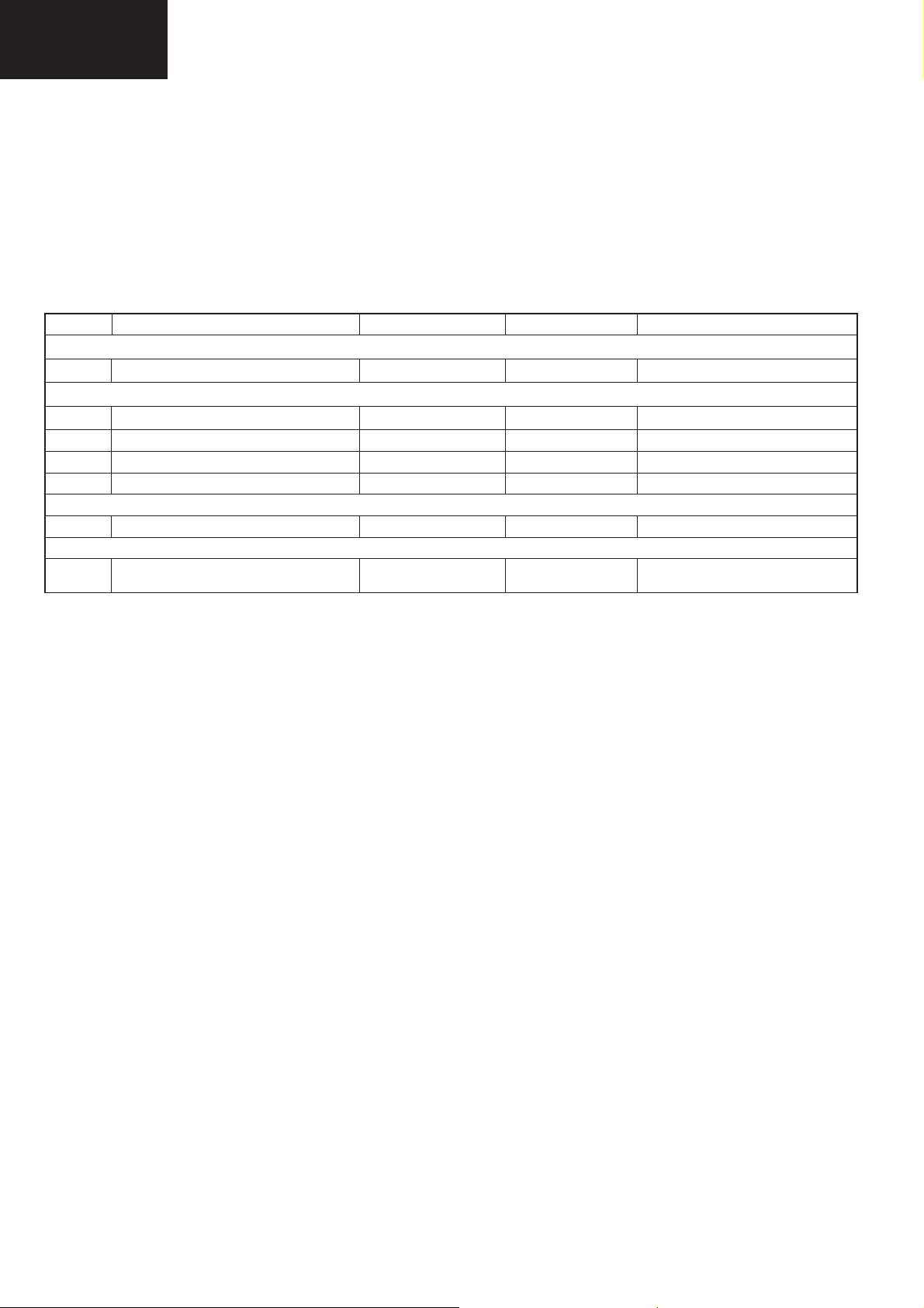
LIST OF CHANGED PARTS
Ref. No. Description LC-32DH510E LC-32DH510EB Note
LCD PANEL
- LCD Panel Module Unit R1LK315T3LA57Y R1LK315T3LF23Y Panel changed
PRINTED WIRING BOARDS ASSEMBLIES
- MAIN / LED Unit Set DSETUF261WE05 DSETUF261WE07 Some parts changed
- MAIN Unit DUNTKF261FM05 DUNTKF261FM07 Some parts changed
- LED Unit DUNTKF262FM05 DUNTKF262FM07 -
- Power Unit RDENCA366WJQZ RDENCA402WJQZ Some parts changed
CABINET & MECHANICAL PARTS
(LV) Coaxial wire (LV) (Control-Main) QCNW-K863WJQZ QCNW-K638WJZZ Wire changed
MAIN Unit
IC1007 FLASH MEMORY.
AND LC32DH510_MERGE_Vx.x
RH-IXD012WJZZY
RH-IXD147WJZZY RH-IXD216WJZZY Changed Software
2
Page 3

Specifi cations
LC-32DH510EB
ELECTRICAL SPECIFICATIONS
Item
LCD Panel 32" Advanced Super View & BLACK TFT LCD
Resolution 1,049,680 pixels (1,366 x 768)
Video Colour System PAL/SECAM/NTSC 3.58/NTSC 4.43/PAL 60
TV Standard Analogue CCIR (B/G, I, D/K, L/L’)
TV
Functions
Backlight life 60,000 hours (when “Backlight” is set the STANDARD, the default position)
Viewing angles H: 176°, V: 176°
Audio Ampli¿ er 10 W x 2
Speaker (35 mm x 100 mm) x 2
Terminals
OSD language
Power Requirement AC 220–240 V, 50 Hz
Power Consumption (IEC62087 Method) 104W (0.20 W Standby)
Weight 9,4 Kg (Without stand), 11,1 Kg (With stand)
Operating Temperature 0 °C to +40 °C
Receiving Channel
TV-Tuning System Auto Preset 999 ch: non-Nordic / 9999 ch: Nordic (ATV: 99 ch), Auto Label, Auto Sort
STEREO / BILINGUAL NICAM/A2
TV Antenna UHF/VHF 75 Din type (Analogue & Digital)
SERVICE Ø 3.5 mm jack
SCART1 SCART (AV input, RGB input, TV output)
SCART2 SCART (AV input/ monitor output, Y/C input)
COMPONENTS COMPONENT IN: Y/PB(CB)/PR(CR), RCA pin (AUDIO R/L)
HDMI1 HDMI, Ø 3.5mm jack
HDMI2 HDMI, Ø 3.5mm jack
AV RCA connector (AV input)
MEDIA PLAYER USB 2.0 HOST (A type)
DIGITAL AUDIO OUTPUT S/PDIF digital audio output.
C. I. (Interface Common) EN50221, R206001
Headphones Ø 3.5 mm jack (Audio output)
Digital DVB-T (2K/8K OFDM)(H.264)
VHF/UHF E2–E69 ch, F2–F10 ch, I21–I69 ch, IR A–IR J ch (Digital: IR A ch–E69 ch)
CATV Hyper-band, S1–S41 ch
32" LCD
COLOUR TV, Model: LC-32DH500E, LC-32DH500S, LC-32DH510E, LC-32DH510S
32" WXGA
Czech, Danish, Dutch, English, Estonian, Finnish, French, German, Greek, Hungarian, Italian,
Latvian, Lithuanian, Norwegian, Polish, Portuguese, Russian, Slovak, Slovene, Spanish,
Swedish, Turkish, Ukrainian
LC-32DH510EB
Environmental Specifi cations
*1 On-Mode (W) (HOME MODE) 81 W
*2 Energy-Save-Mode (W) ECO 65 W
*3 Standby-Mode (W) 0.20 W
*4 Off Mode (W) 0.17 W
*5 Annual Energy Consumption (kWh) 119kWh
*6 Annual Energy Consumption
Energy-Save-Mode (kWh)
NOTE
The power consumption of On-Mode varies depending on the images the TV displays.•
ECO 95kWh
Cautions regarding use in high and low temperature environments
• When the unit is used in a low temperature space (e.g. room, offi ce), the
picture may leave trails or appear slightly delayed. This is not a malfunction, and the unit will recover when the temperature returns to normal.
• Do not leave the unit in a hot or cold location. Also, do not leave the
unit in a location exposed to direct sunlight or near a heater, as this may
cause the cabinet to deform and the LCD panel to malfunction. Storage
temperature: –20°C to +60°C
.
3
*1 Measured according to IEC 62087 Ed. 2.
*2 For further information about the Energy Save
function, please see related pages in this operation
manual.
*3 Measured according to IEC 62301 Ed. 1.
*4 Measured according to IEC 62301 Ed. 1.
*5 Annual energy consumption is calculated on the
basis of the On-Mode (HOME MODE) power
consumption, watching TV 4 hours a day, 365
days a year.
*6 Annual energy consumption is calculated on
the basis of the Energy-Save-Mode power
consumption, watching TV 4 hours a day, 365
days a year.
• As a part of our policy of continuous improvement, SHARP reserves the right to
make design and specifi cation changes
for product improvement without prior
notice. The performance specifi cation fi g-
ures indicated are nominal values of production units. There may be some deviations from these values in individual unit
s.
Page 4

LC-32DH510EB
IMPORTANT SERVICE SAFETY PRECAUTION
Service work should be performed only by qualifi ed service technicians who are thoroughly familiar with all
safety checks and the servicing guidelines which follow:
WARNING
1. For continued safety, no modifi cation of any circuit should be attempted.
2. Disconnect AC power before servicing.
CAUTION: FOR CONTINUED PROTECTION AGAINST A RISK OF
FIRE REPLACE ONLY WITH SAME TYPE
F101, F102 (T3.15AH / 250V)
BEFORE RETURNING THE RECEIVER (Fire & Shock Hazard)
Before returning the receiver to the user, perform the following safety checks:
1. Inspect all lead dress to make certain that leads are not pinched, and check that hardware is not lodged between the
chassis and other metal parts in the receiver.
2. Inspect all protective devices such as non-metallic control knobs, insulation materials, cabinet backs, adjustment and
compartment covers or shields, isolation resistor-capacitor networks, mechanical insulators, etc.
3. To be sure that no shock hazard exists, check for leakage current in the following manner.
•Plug the AC cord directly into a 220~240 volt AC outlet. (Do not use an isolation transformer for this test).
•Using two clip leads, connect a 1.5k ohm, 10 watt resistor paralleled by a 0.15μF capacitor in series with all exposed metal
cabinet parts and a known earth ground, such as electrical conduit or electrical ground connected to an earth ground.
•A true RMS reading multimeter should be used for this test, especially where the equipment uses a switch mode
power supply which may result in very non-sinusoidal leakage current.
•Connect the resistor connection to all exposed metal parts having a return to the chassis (antenna, metal cabinet,
screw heads, knobs and control shafts, escutcheon, etc.) and measure the AC voltage drop across the resistor.
All checks must be repeated with the AC cord plug connection reversed. (If necessary, a nonpolarized adaptor plug must
be used only for the purpose of completing these checks.)
Any reading of 1.05V peak (this corresponds to 0.7 mA. peak AC.) or more is excessive and indicates a potential shock
hazard which must be corrected before returning the monitor to the owner.
DVM
AC SCALE
1.5k ohm
10W
0.15 μF
TEST PROBE
TO EXPOSED
METAL PARTS
CONNECT TO
KNOWN EARTH
GROUND
SAFETY NOTICE
Many electrical and mechanical parts in LCD television have special safety-related characteristics.
These characteristics are often not evident from visual inspection, nor can protection afforded by them be necessarily
increased by using replacement components rated for higher voltage, wattage, etc.
Replacement parts which have these special safety characteristics are identifi ed in this manual; electrical components
having such features are identifi ed by “ “.
!
For continued protection, replacement parts must be identical to those used in the original circuit.
The use of a substitute replacement parts which do not have the same safety characteristics as the factory recommended
replacement parts shown in this service manual, may create shock, fi re or other hazards.
4
Page 5
LC-32DH510EB
PRECAUTIONS FOR USING LEAD-FREE SOLDER
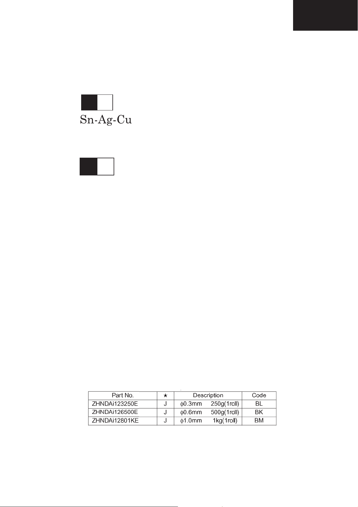
1 Employing lead-free solder
“ALL PWB” of this model employs lead-free solder. The LF symbol indicates lead-free solder, and is attached on the
PWBs and service manuals. The alphabetical character following LF shows the type of lead-free solder.
Example:
L Fa
Indicates lead-free solder of tin, silver and copper.
L F n
Sn-Ag-Ni
Indicates lead-free solder of tin, silver and nickel.
2 Using lead-free wire solder
When fi xing the PWB soldered with the lead-free solder, apply lead-free wire solder. Repairing with conventional lead
wire solder may cause damage or accident due to cracks.
As the melting point of lead-free solder (Sn-Ag-Cu) is higher than the lead wire solder by 40°C, we recommend you to
use a dedicated soldering bit, if you are not familiar with how to obtain lead-free wire solder or soldering bit, contact our
service station or service branch in your area.
3 Soldering
As the melting point of lead-free solder (Sn-Ag-Cu) is about 220°C which is higher than the conventional lead solder by
40°C, and as it has poor solder wettability, you may be apt to keep the soldering bit in contact with the PWB for extended
period of time. However, Since the land may be peeled off or the maximum heat-resistance temperature of parts may be
exceeded, remove the bit from the PWB as soon as you confi rm the steady soldering condition.
Lead-free solder contains more tin, and the end of the soldering bit may be easily corroded. Make sure to turn on and
off the power of the bit as required.
If a different type of solder stays on the tip of the soldering bit, it is alloyed with lead-free solder. Clean the bit after every
use of it.
When the tip of the soldering bit is blackened during use, fi le it with steel wool or fi ne sandpaper.
Be careful when replacing parts with polarity indication on the PWB silk.
Lead-free wire solder for servicing.
5
Page 6

LC-32DH510EB
END OF LIFE DISPOSAL
A. Information on Disposal for Users (private households)
1. In the European Union
Attention: If you want to dispose of this equipment, please do not use the ordinary dust bin!
Used electrical and electronic equipment must be treated separately and in accordance with legislation that requires
proper treatment, recovery and recycling of used electrical and electronic equipment.
Following the implementation by member states, private households within the EU states may return their used
Attention: Your product
is marked with this
symbol. It means that
used electrical and
electronic products
should not be mixed
with general household
waste. There is a
separate collection
system for these
products.
electrical and electronic equipment to designated collection facilities free of charge*. In some countries* your local
retailer may also take back your old product free of charge if you purchase a similar new one.
*) Please contact your local authority for further details.
If your used electrical or electronic equipment has batteries or accumulators, please dispose of these separately
beforehand according to local requirements.
By disposing of this product correctly you will help ensure that the waste undergoes the necessary treatment, recovery
and recycling and thus prevent potential negative effects on the environment and human health which could otherwise
arise due to inappropriate waste handling.
2. In other Countries outside the EU
If you wish to discard this product, please contact your local authorities and ask for the correct method of disposal.
For Switzerland: Used electrical or electronic equipment can be returned free of charge to the dealer, even if you don’t
purchase a new product. Further collection facilities are listed on the homepage of www.swico.ch or www.sens.ch.
B. Information on Disposal for Business Users
1. In the European Union
If the product is used for business purposes and you want to discard it:
Please contact your SHARP dealer who will inform you about the take-back of the product. You might be charged for
the costs arising from take-back and recycling. Small products (and small amounts) might be taken back by your local
collection facilities.
For Spain: Please contact the established collection system or your local authority for take-back of your used
products.
2. In other Countries outside the EU
If you wish to discard of this product, please contact your local authorities and ask for the correct method of disposal.
The battery supplied with this product contains traces of Lead.
For EU: The crossed-out wheeled bin implies that used batteries should not be put to the general household waste!
There is a separate collection system for used batteries, to allow proper treatment and recycling in accordance with
legislation. Please contact your local authority for details on the collection and recycling schemes.
For Switzerland: The used battery is to be returned to the selling point.
For other non-EU countries: Please contact your local authority for correct method of disposal of the used battery.
6
Page 7

LC-32DH510EB
SERVICE ADJUSTMENTS
1. Adjustment method after PWB and/or IC replacement due to repair
The unit is set to the optimum at the time of shipment from the factory.
If any value should become improper or any adjustment is necessary due to the part replacement, make an adjust-
ment according to the following procedure.
1.1. Procure the following units in order to replace the main unit:
MAIN UNIT DUNTKF261FMxx
NOTE: [Caution when replacing ICs in the main unit (IC1901, IC1902, IC1006 and IC1007)]
Before replacing the relevant part, procure the following parts in which the data have been rewritten.
Ref. Description Parts code IC + data Description new IC code for service
IC1901 HDMI EDID 1 RH-IXD041WJZZY VHIM24C02W61EY AND DATA LC32DH500E_HDMI_1_EDID
IC1902 HDMI EDID 2 RH-IXD042WJZZY VHIM24C02W61EY AND DATA LC32DH500E_HDMI_2_EDID
IC1006 HDCP USER SETTINGS RH-IXD043WJZZY RH-IXC986WJZZY AND DATA LC32DH500E_HDCP_KEY
IC1007 FLASH MEMORY RH-IXD216WJZZY
RH-IXD012WJZZY AND LC32DH510EB_MERGE_V1.0
2. Entering and exiting the adjustment process mode. Standard method.
1. By key-unit.
1. Unplug the AC power cord.
2. Press and hold “V-” and “b” keys, simultaneously, and then plug the AC power cord.
3. “K” appears on the screen.
4. Press and hold “V-” and “P-” keys, simultaneously.
5. “SHARP FACTORY MENU” appears (see Figure 1).
6. Unplug the AC power cord to exit of adjustments process.
2. By own R/C
1. Turn on the TV set.
2. Press “b”,”2”,”5”, “8”, “0” (the time is limited to 5 sec. approx., to enter this code).
3. “SHARP FACTORY MENU” appears (see Figure 1).
4. Press “OK” on lines 5 ~ 12 to go to submenu.
5. Press “MENU” to return to main menu.
6. Press “END” to exit of adjustments mode.
7
Page 8

LC-32DH510EB
3. Remote control key operation and description of display in adjustment process mode.
1. key operation
Remote control key Keyboard unit Function
Cursor (▼/▲ ) P (s/r) Moving an item (line) by one (up/down) on “Sharp Factory Menu”
or submenus.
OK
b
Selecting a submenu on lines 5 to 12 of “Sharp Factory Menu” or
executing a function.
Cursor (◄/►) V (+/-) Changing a selected item setting value.
MENU MENU Return to “Sharp Factory Menu” from a submenu.
The required input mode should be switched previously to enter the Service Mode.
CAUTION: Use due care in handling the information described here lest the users should know how to enter the
adjustment process mode. If the settings are tampered with in this mode, unrecoverable system
damage may result.
4. Description of display
Figure 1: Main Service Adjustment Menu
SHARP FACTORY MENU
Main version
Boot loader version BD_MST064E_C01A 2
Normal standby cause Remote control
Error standby cause None
INIT
ADJUST
ETC
PUBLIC MODE
SMARTLOADER
ADC ADJUST
GAMMA
SYSTEM INFORMATION
32DH510EB SHARP v1.01 SEES v74t MSTAR CL233434
(1)
← Informative (Main microprocessor version).
← Informative.
← Informative (Remote Control/Keyboard…).
← Informative (None/Lamp Error).
← Press “OK” to go to INIT submenu.
← Press “OK” to go to ADJUST submenu.
← Press “OK” to go to ETC submenu.
← Press “OK” to go to PUBLIC MODE submenu.
← Press “OK” to go to SMARTLOADER submenu.
← Press “OK” to go to ADC ADJUST submenu.
← Press “OK” to go to GAMMA submenu.
← Press “OK” to go to SYSTEM INFORMATION submenu.
(2) (3)
No. Description Display specifi cation
(1) Service Information Current Software version and others.
(2) Item name Submenus to be checked or adjusted (by pressing “OK” button)
(3) Factory init and Inch setting Are shown on INIT submenu
8
Page 9

5. Adjustment process mode menu
LC-32DH510EB
Page Line Sub
Page
01/17 [SHARP FACTORY MENU
1 Main Version
2 Bootloader Version BD_MST064E_C01A Informative only
3 Normal Standby Cause
4 Error Standby Cause None / Lamp Error Informative only
5 INIT Factory Init Submenu Press “OK” to enter to Factory Init Submenu
02/17 Factory Init EURO I
6 ADJUST QMAP ADJUST Submenu Press “OK” to enter to QMAP ADJUST Submenu
03/17 INPUT SOURCE (1/6) DTV/ RF/Multimedia ...
04/17 INPUT SOURCE (2/6) DTV/ RF/Multimedia ...
05/17 INPUT SOURCE (3/6) DTV/ RF/Multimedia ...
Item Description Remarks (adjustment details, etc.)
Inch Setting SH32_LK315T3LA57 Panel type
Center Acutime 64 H 40 M
RESET “OK” Will be displayed
AFEC Only for Engineering purpose (Please don’t use)
Comb Only for Engineering purpose (Please don’t use)
SECAM Only for Engineering purpose (Please don’t use)
SCinit Only for Engineering purpose (Please don’t use)
CSC OFF Only for Engineering purpose (Please don’t use)
CSC_Dither OFF Only for Engineering purpose (Please don’t use)
YCdelay OFF Only for Engineering purpose (Please don’t use)
PreFilter Fir 66 Only for Engineering purpose (Please don’t use)
HSD_Y ALL PASS1X Only for Engineering purpose (Please don’t use)
HSD_C ALL PASS1X Only for Engineering purpose (Please don’t use)
VSD OFF Only for Engineering purpose (Please don’t use)
CTI CTI_0 Only for Engineering purpose (Please don’t use)
MemFormat 422MF Only for Engineering purpose (Please don’t use)
444To422 ON Only for Engineering purpose (Please don’t use)
PreSNR PS-3 Only for Engineering purpose (Please don’t use)
DNR ON Only for Engineering purpose (Please don’t use)
DNR_Motion MR_NR Only for Engineering purpose (Please don’t use)
DNR_Y DY-3 Only for Engineering purpose (Please don’t use)
NDR_MED OFF Only for Engineering purpose (Please don’t use)
DNR_C DC-3 Only for Engineering purpose (Please don’t use)
PNR AVG-ON Only for Engineering purpose (Please don’t use)
PNR_Y OFF Only for Engineering purpose (Please don’t use)
PNR_C OFF Only for Engineering purpose (Please don’t use)
PostCSS OFF Only for Engineering purpose (Please don’t use)
PostCSS_Smooth PCS_6 Only for Engineering purpose (Please don’t use)
420CUP ON Only for Engineering purpose (Please don’t use)
MADi 25_4R Only for Engineering purpose (Please don’t use)
MADi_Motion MOT_4R_5 Only for Engineering purpose (Please don’t use)
MADi_ADP3x3 ADP1 Only for Engineering purpose (Please don’t use)
MADi_MORPHO M1 Only for Engineering purpose (Please don’t use)
MADi_DFK DFK1 Only for Engineering purpose (Please don’t use)
32DH510EB SHARP v1.01
SEES v74t MSTAR CL233434
Remote Control / Keyboard...
Informative only (Main microprocessor version)
Informative only
nformative (EURO/RUSSIA/SWEDEN/UK/EAST EUROPE)
Press “◄ “ or “ ►” to reset (“OK” will be displayed)
9
Page 10

LC-32DH510EB
Power Unit Layout RDENCA402WJQZ
I
H
G
CHASSIS LAYOUT
F
E
RDENCA402WJQZ
D
C
B
A
1
2
3
4567
10
Page 11

OVERALLL WIRING DIAGRAM
LC-32DH510EB
5
KM
P151
1
KEY UNIT
I
(DUNTKE266WE)
QPLGNQ059WJZZ
H
G
MEDIA
PLAYER
USB
F
HEADPHONES
KM
MAIN UNIT
(DUNTKF261WE)
C.I.
INPUT
COMPONENTS / AV
Y/AV
Pb
Pr
L
R
(AV / S-VIDEO)
SCART 2
[ ] Only for DH500EB & DH510EB
Z Q J W 0 6 6 G - W N C Q
4 1
P3071
KM
QPLGNA324WJZZY
TUNER
ANT
DIGITAL AUDIO
OUTPUT
SPDIF
SCART 1
(AV / RGB)
SERVICE
RS232
HDMI 2
HDMI 1
AUDIO IN
HDMI (DVI)
MEMORY
MEMORY
MSTAR
PD
P1701
1
QCNW-K097WJZZ
PD
13
QPLNGA185WJZZY
QPLGNA493WJZZY
32
LV
1
LV
SC8201
INVERTER UNIT
POWER UNIT RDENCA366WJQZ [RDENCA402WJQZ]
RDENCA402WJQZ
CN1
1
LA
QCNW-J655WJZZ
14
T1
T2
T3
T4
T5
CN2
CN3
CN4
E
RA
QPLGNA563WJZZY
15
RA
P2301
SP
D
QCNW-K109WJQZ
QCNW-K098WJQZ
QPLGNA160WJZZY
1
4
P2701
SP
QCNW-K156WJPZ
[QCNW-K638WJPZ]
QCNW-K863WJPZ
QCNW-K638WJQZ
T7 T6
T8
CN5
C
LED UNIT
B
(DUNTKF262WE)
RA
P5101
1 5
QPLGNA339WJZZY
RSP-ZA356WJZZ [RSP-ZA322WJZZ]
RSP-ZA355WJZZ [RSP-ZA321WJZZ
SP-R
SP-L
A
1
2345678910
11 12
13
14
15 16
11
Page 12

LC-32DH510EB
SYSTEM BLOCK DIAGRAM
LCD_PANEL
I
H
G
F
E
Tuner_ CVBS
D_IF IN P/N
D
Audio
Analog in
SC1902
C
LC-32DX50 BLOCK DIAGRAM
CVBS IN
AUDIO L-R IN
RGB IN
Tuner
TU 201
PCMCIA
P2701
CVBS OUT
AUDIO L-R OUT
RGB FAST SW
SLOW SW
CVBS IN 2
AUDIO L-R IN 2
CVBS OUT 2
AUDIO LR OUT 2
SLOW SW
TS
PARALLEL TS
I2C EDID 2
I2C EDID 1
SCART 1
SCART 2
Headphone
IF AGC
SC1901
HDMI 1
HDMI 2
SP
SIF
(DUNTKF261WE__)
(QPWBXF261WJN_ )
IC301 OP Amp
VHINJM3414V
IC303 OP Amp
VHINJM3414
IC309 HP out
VHIBH3544F
IC306 SP Amp
RH-IXC867WJ
Mute _speaker
IC201 COFDM
Bus I2C
MSB1220
VCC_PCMCIA
IC308
VHINJM3414V
TS
Audio out scart 2
IC1902
EEPROM
Audio out scart 1
Mute audio scart
Bus I2C
WP
INV-UNIT
QCNW-F068WJQZ
QCNW-K638WJQZ
VBLCTRL_P2
SC8201 LV
Led Unit RA
PD
P3071
P1701
QCNW-G662WJQZ
QCNW-J717WJQZ
R/C LED UNIT
(DUNTKF262WE__)
RA
BU+3.3V
2
3
4
5
P5101
POWER-UNIT
RDENCA366WJZZ
RDENCA402WJQZ
1 2
R/C
31
VCC
2
GND
1
OUT
IR RECEIVER MODULE
3 4
RMC5101
UA053WJ
TV POW
PX0421CE
D5103
12
4
3
R
G/B
5 6 8
7
LA
QCNW-J656WJQZ
MAIN-UNIT
MUTE_S
SC_VIDEO_OUT
SCART_RGB_IN
AUDIO_OUT_SCART 1
AUDIO_OUT_SCART 2
SC_CVBS IN2
SC_AUDIO IN2
SC_CVBS OUT2
SLOW_SW2
MUTE_EAR
AU_DACO_L/R
Mute _speaker
Tuner_CVBS
SIF
TS no scrambled
TS descrambled
HDMI 1
EDID WP
Q201
HDMI 2
Audio analog IN
HDMI 1
HDMI 2
COMP_AUR/ L2
SPDIF
RGB_YPbPr
SC_AUDIO_IN
USB
FS_SW
SC_CVBS_IN
IC1001
MSD3303GX
RH-IXC869WJ
Video audio
processor
RS232
SLOW_SW
I2C
POWER_SW
LVDS out
VBLCTRL_P2
Power_SW
Power_button
SAR0
SAR1
IRIN
IC1007 Serial
Flash 128 Mb
IC1002
RH-IXC505WJ
DDR2 512Mb
IC1003
RH-IXC505WJ
DDR2 512M
IC1005 NVM
M24C04
U12
AT24C512 N
NVM HDCP
Vcc12V
Vcc5V
33V_Normal
Power_SW
Bus I2C
Bus I2C
XS4 SPDIF
B
YPbPr / RGB
IC305
NC7SZ04P
A
1
2345678910
IC1901
EEPROM
COMP_AU R/ L2
WP
CH-UP
S151
K0003AJ
J4001
USB
RS232
KM
1
2
3
P151
L-PSR-PS
ZZJW553AZ-PSRZZJW653AZ-PSR
R151
8.2K
1/8W
CH-DOWN
S152
K0003AJ
(DUNTKE266WE__)KEY UNIT
R152
12K
1/8W
INPUT
S153
K0003AJ
VOL-UP
S154
K0003AJ
R153
1/8W
8.2K
VOL-DOWN
S155
K0003AJ
R154
12K
1/8W
MENU
S156
K0003AJ
11 12
POW
S157
K0003AJ
13
14
15 16
12
Page 13

POWER BLOCK DIAGRAM
I
L
AC
INLET
220VAC
N
H
G
F
JUMPERS SETTINGS
E
D
C
B
A
SERIES J201 J202 J203 SHARP CODE
DH500 X X RDENCA366WJQZ
DH500B X RDENCA402WJQZ
DH510 X X RDENCA366WJQZ
DH510B X RDENCA402WJQZ
12345 67891011121314
F101
3_15A
VA101
F102
3_15A
TH101
400V
GND24V ERR
TO INVERTER
VCC
EMI FILTER
LF101/102
CX101
Q603
BLON
VCC
CX102
C504
P1
C109/108
ZD505
Q604
PFC Controller
PWM
J201
J202
J203
PSON
31219452 13
TO MAIN
BD101
8
1
3
C608
P2
U601
NCP1607
VCC
FB
CT
CONTROL
P1
L601
PPC
INDUCTOR
ZCD
DRV
CS
GND
2
5
7
4
6
5.75V
L602
400V
C101 OVP Protection
GND
D601
1171068
D602
PFC
DRIVER
Q601
R522
+12V
PC102.
5VS
Add this jumper to force start up PSU
PRIMARY
VOLTAGE
400V
VCC
P802P801
VCC
C101
Q504
PC101_
Q105
C144
C105
DZ503
MAIN RESONAT POWER
CONTROLLER
U101
SSC9502
1
VSEN
2
VCC
4
SGND
CSS
3
FB
PC501.
Q502
P2
Q503
C604
LC-32DH510EB
LC32DH500E POWER SUPPLY BLOCK DIAGRAM
2010 01 20
POWER DRIVERS
ZD100
STANBY
CONTROLLER
U501
A6069H
4
FB
3
GND
2
BR
Q101
Q102
VCC
5
OCP
C509
C201
C221
R201...206
D205
+12V
Dumy Load
+24/+12V
REG.
Q203
PC502PC501
ON/OFF
PC102
R207...242
Q201
Q204
S3 S324V
L202
PSON
S3
L203
Q202
Q206
ZD201
Q205
C202
MAIN POWER
TRANSFORMER
C103
STANBY
TRANSFORMER
T501
8
D
7
D
1
R522
D505
D203
5VS/5.75V
REG.
PC101
V201
C204
V202
S1
C207
SECUNDARY
OVERVOLTAGE
+24V/5A
+12V/3A
C203
GND
5.75V/2.2A
C205
5VS/60mA
C208
PSON
ZD202
VGH
D105
REG
14
VB
15
VS
C108
11
VGL
10
COM
6
OC
RC
R138
R139
C124
R523
PC502.
1
2345678910
11 12
13
14
15 16
13
Page 14
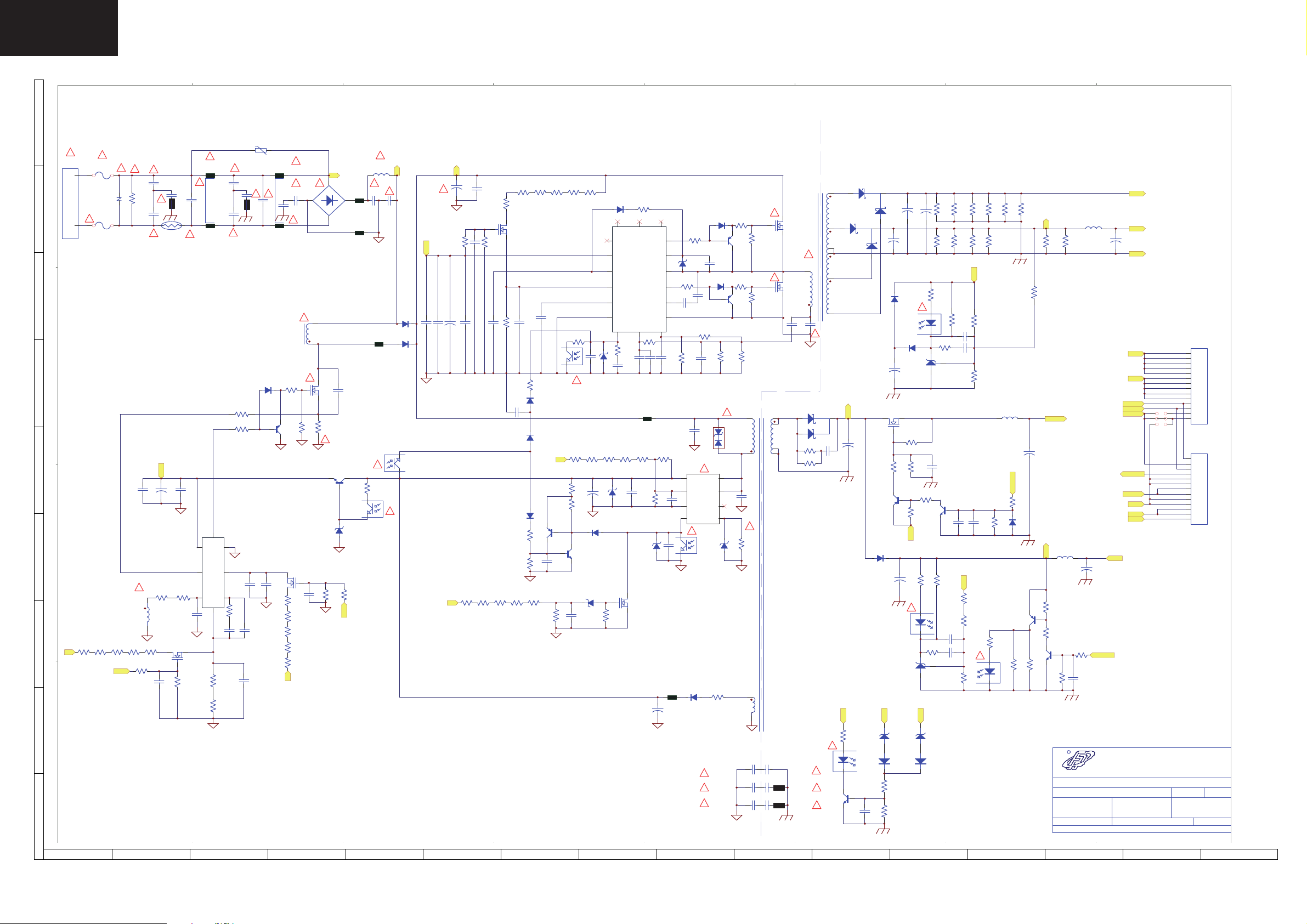
LC-32DH510EB
(
Power Supply Diagram RDENCA402WJQZ
I
SA101
CY106
221P/Y1
FB204
LF102:2
C606
R627
104P
C612
N.C.
8LM02556
"
CX102
D603
4148
C608
DSPL-301N-A21F
LF102:1
1 2
CY107
"
N.C.
N.C.
CY108
34
R622
15 ohm
Q604
680P
C607
R605
R604
R603
R602
R601
"
"
N.C.
"
Q602
4403
AP01L60T
1M,F
1M,F
1M,F
1M,F
1M,F
P1
"
103P
L602:8
8TI00605
L602:1
"
5N50C
R623
36K
KSP2222A
"
"
51K
C613
P2
BD101
Q601
R621
Q503
ZD503
D3SBA60
FB101
FB102
C603
100P/1KV
0.13 ohm/2WS
16B
5.1K
R633
Vcc
12
12
PC502:1
R634
L601
8LM01612
"
C601
474P/450V
FB601
"
R529
5.1K
3 4
"
C602
12
"
EL817
"
105P/500V
D602
P1
S3V60
D601
RY2A1
34
PC102:1
EL817
C101
100uF/450V
Vcc
C112
N.C.
"
C119
N.C.
B+
C102
+
5.1K
10uF/50V
+
R136
C105
C118
C117
104P
103P
N.C.
R135
51K
C120
R137
C116
104P
1.2M,F
R106
100 ohm
AP01L60T
Q105
R133
27K,F
104P
D106
D504
4148
R527
1K
R528
47K
R105
C115
104P
1.2M,F
R134
D101
4148
1K
4148
334P
1.2M,F
R104
C114
Q501
4403
105P
C508
680,F
P2
R103
3 4
1.5M,F
R525
R526
1.2M,F
1.2M,F
R102
R132
EL817
"
PC101:1
R501
R502
9.1K,F
1K
Q502
4401
1.5M,F
C504
22uF/50V
D503
4148
102P
C113
+
12
2
8
1
5
4
9.1B
ZD102
R503
1.5M,F
ZD505
D105
UF4007
13
N.C.
N.C.
VCC
Reg
Vsen
CSS
SGND
FB
3
1.5M,F
R504
36B
47K
105P
C111
C505
R127
10 ohm
17
U101
SSC9502
6
R131
R505
1.5M,F
104P
ZD502
N.C.
PGND
OC
R130
680,F
100P
C110
FB502
1 2
R524
16B
VGH
VB
VS
VGL
RV
N.C.
C122
R523
1.2M,F
18
N.C.
RC
7
N.C.
C121
143K,F
16
14
15
11
9
10
C501
102P
R126
36 ohm
C107
C108
N.C.
2
472P
3
C506
3 4
R123
36 ohm
ZD101
16B
22P/1KV
R138
N.C.
R139
Vcc5D
U501
BR
A6069H
GND
FB4S/OCP
"
EL817
PC501:1
102P
C109
"
N.C.
C507
1M,F
1M,F
R507
R508
1M,F
1M,F
R509
R510
1M,F
R506
B+
ZD504
16B
C510
105P
270K,F
R531
R532
100K
Q504
2N7002
C509
47uF/50V
FB503
+
D505
12
UF4007
"
L
"
F101
T3.15A H/250V
SC101:2
TVR14621
"
T3.15A H/250V
F102
"
VA101
"
R101
1.5M/0.5W
"
221P/Y1
CY101
"
221P/Y1
CY102
"
CY103
221P/Y1
TH101
SCK-015
SC101
H
N
ST-02G-AAFBF
SC101:1
FB203
CX101
"
"
8LM02556
LF101:1
1 2
"
224P/275V
34
LF101:2
"
221P/Y1
CY104
221P/Y1
CY105
"
G
F
510 ohm
U601
NCP1607
51 ohm
678
2345
1
224P
R628
14.7K,F
R629
0 ohm
R624
R625
102P
36K
C609
N.C.
C614
Vcc
+
C604
C605
10uF/50V
104P
E
D
"
L602:5
L602:6
470K,F
470K,F
R607
R608
470K,F
R610
470K,F
R609
5.1K
Vcc
R631
C
R606
B+
470K,F
R632
10K
N.C.
R626
10 K
C610
Q603
C611
10P
AP01L60T
R630
51K
D103
D104
22P/1KV
D
R530
1.5 ohm
4148
C106
104P
4148
4403
0 ohm
1.62K,F
Q103
R129
"
D501
STO2D-170
8
7
6
1
16B
T501:6
QSJNBSZ
1.62K,F
R128
N.C.
"
R522
R122
36K
T501:3
C503
1.2 ohm/2WS
R125
"
"
36K
C104
T501:7
T501:8
T501:10
R121
10 ohm
4403
R124
10 ohm
Q104
T501:1
8TA00431
ZD501
T501:5
Q101
5N50C
T101:5
8TE00295
Q102
5N50C
T101:2
100 ohm
T501:9
22P/1KV
"
C103
223P/1KV
D203
R221
R227
100 ohm
B
102P/Y1
102P/Y1
102P/Y1
102P/Y1
102P/Y1
102P/Y1
CY110
FB201
CY112
FB202
CY114
"
"
"
CY109
CY111
CY113
A
1
2345678910
TFDPOEBSZ
T101:8
FMEN-220A
T101:11
FMW-2156
T101:9
T101:10
T101:12
T101:7
"
FMEN-210A
"
"
"
S1
+
C206
102P/200V
S3
R238
330 ohm
"
12
EL817
KSP2222A
Q205
C218
11 12
D202
C204
1000uF/16V
PC102:2
105P
D201
R228
Q204
D205
1N4007
C202
C209
Q201
5.1K
4403
PC501:2
24V
R240
1K
R241
27K
C201
+
D206
4148
+
2.2uF/50V
R244
+
EL817
U202
AZ431
ZD201
27B
D213
4148
1000uF/35V
+
C221
1000uF/25V
"
PC101:2
D207
4148
AP60T03GH
30K
51K
R229
R233
R232
3.9K
12V
C207
470uF/10V
"
12
1 2
1000uF/35V
+
R230
5.1K
S3
ZD202
R213
1K
EL817
12
U201
10K
R224
330 ohm
3
6.2B
D212
4148
16K
10K
R217
5.1K
AS431
C217
105P
Q203
C215
C216
R231
8.2K,F
R201
R207
4401
C213
N.C.
R225
6.8K
224P
16K
10K
R215
3.9K
103P
224P
103P
R202
R208
S1
R226
100,F
R219
10.7K,F
EL817
R203
16K
16K
R209
10K
10K
24V
R216
18.7K,F
C210
C212
R218
1.13K,F
C219
104P
"
12
PC502:2
R204
R210
L202
8LR00530
10K
6.2K
R223
1.8K
13
16K
R214
PS-ON
R234
Q202
4403
R245
910 ohm
R205
9.1K,F
N.C.
16K
R235
D208
R236
910 ohm
R206
+
470uF/10V
S2
10K
5.75V/2.2A
5.75V
L201
8LR00530
R211
R212
10K
+
C203
100uF/25V
BLON
I-PWDM
GND
ERR
C205
PS-ON
5.75V
GND
S3
L203
8LR00530
R242
1K
R222
5.1K
Q206
4401
6.2K
R237
FSP GROUP
TILE:
P/N:
APPROVED:
R
5Vs/0.06A
5Vs
+
C208
100uF/25V
10K
R243
PS-ON
C220
104P
٤ዧٞᄐٝڶૻֆ
FSP Technology Inc.
FSP170-4F01
3BS0234311GP
CHECKED:
LJ Paul Gigi
Date: 2009/9/7
File:
D:\Layout-AD6\
PCB File:FSP170-4F01-R0
࿇۩֮ٙ
\170W\FSP170-4F01-R1 (SHARP 32)\FSP170-4F01-R1
ᒵሁቹ
ᒳᇆ
14
24V
24V/5.0A
12V
12V/3.0A
GND
A2001WR2-14P
24V
J201
J202
J203
12V
5Vs
A2001WR2-13P
size: A2 rev:1
DESIGNER:
:7000P-0106
15 16
P801
1
2
3
4
5
6
7
8
9
10
11
12
13
14
P802
1
2
3
4
5
6
7
8
9
10
11
12
13
Sheet of00
14
Page 15

PRINTED WIRING BOARD
Power Unit PWB (RDENCA402WJQZ)
I
Power Unit, Side A
H
G
LC-32DH510EB
F
E
RDENCA402WJQZ
D
C
B
A
1
2
3
4 567
15
Page 16

LC-32DH510EB
Power Unit PWB (RDENCA402WJQZ)
I
Power Unit, Side B
H
G
F
E
D
C
B
A
1
2
3
4567
16
Page 17

MARK *: SPARE PARTS DELIVERY SECTION
REF No.
PARTS DESCRIPTION
* SN CODE EX CODE
R1LK315T3LF23Y PANEL 32DH510EB WXGA CM S CF DB
DSETUF261WE07 MAIN/LED UNIT 32DH510EB S AV BG
!
RDENCA402WJQZ POWER SUPPLY S AV BG
LCD PANEL
NOTE : THE PARTS HERE SHOWN ARE SUPPLIED AS AN ASSEMBLY BUT NOT INDEPENDENTLY
PRINTED WIRING BOARDS
DUNTKF261FM07
IC 1007 RH-IXD216WJZZY
RH-IXD012WJZZY AND LC32DH510EB_MERGE_V1.0
SAN AZ
!
RDENCA402WJQZ POWER SUPPLY S AV BG
INTEGRATED CIRCUITS
DUNTKF262FM07
LED Unit
RDENCA402WJQZ
POWER Unit
MAIN Unit
PARTS LISTING
REPLACEMENT PARTS
Replacement parts which have special safety characteristics are identifi ed in
this manual.
Electrical components having such features are identifi ed by in the Replace-
ment Parts Listi
The use of a substitute replacement part which does not have the same safety
characteristics as the factory recommended is not permitted.
Replacement parts not shown in this service manual may create shock fi re, or
other hazards.
To have your order completed promptly and correctly please supply the following information.
1. MODEL NUMBER 2. REF. NO. 3. PART NO.
4. DESCRIPTION 5. CODE 6. QUANTITY
ng.
HOW TO ORDER REPLACEMENT PARTS
!
LC-32DH510EB
17
Page 18

LC-32DH510EB
CABINET AND MECHANICAL PARTS
18
Page 19

CABINET AND MECHANICAL PARTS
REF No. PARTS DESCRIPTION * SN CODE EX CODE
PARTS LISTING
CABINET AND MECHANICAL
11
QCNW-K638WJZZ Cable (LV) P-TWO S AE AN
LC-32DH510EB
19
Page 20

LC-32DH510EB
SHARP CORPORATION
AV System Group
COPYRIGHT © 2010 BY SHARP CORPORATION
ALL RIGHTS RESERVED
No part of this publication may be reproduced,
stored in a retrieval system, or transmitted in any
form or by any means, electronic, mechanical,
photocopying, recording, or otherwise, without
prior written permission of the publisher.
SHARP ELECTRONICA ESPAÑA S.A.
Service Manual Group
Engineering Dept.
C/ Sena, 2-10
08174 Sant Cugat del Vallès
Barcelona
Spain
20
 Loading...