

Page 1

LC-32A33M
LC32AA3M
CHAPTER 5. ADJUSTMENT PROCEDURE
Service Manual
[1] ADJUSTMENT PROCEDURE
The adjustment values are set to their optimum at the factory before shipping. If by any chance a value should become improper or a readjustment is
required due to part replacement, make an adjustment according to the following procedure.
Before adjustment, perform aging for approx. 60 minutes to stabilize the unit.
1. Entering the adjustment process mode
There are 3 ways as follows:
• After power-on, press "ADJUSTMENT PROCESS" key of the remote control.
• With the KEY 4 (pin E1 of IC801) set to "L", turn the power ON.
• During servicing
1
While holding down the TV/VIDEO and Volume DOWN keys at the same time, set the Power switch to ON. (“K” standing for inspection process
mode is displayed in the upper left portion of the screen.) → Press the Channel DOWN and Volume DOWN keys at the same time. (The adjustment process mode screen appears.)
To cancel it, turn off the power using the Power switch or remote control.
2. Key operation in the adjustment process mode
1. Basic operations
• Tune in to a station using the Channel UP/DOWN keys.
• Switch the input using the TV/VIDEO key.
• Select an item to adjust using the Cursor / keys. (Pressing the Cursor key while at the bottom item moves to the top item on the
next page, and pressing the Cursor key while at the top item moves to the bottom item on the previous page.)
• Adjust the item selected using the Volume +/– or Cursor / keys.
• Press the Menu key to move to the next item. (Pressing the Menu key while at the bottom item moves to the top item on the next page.)
• Press the Manual Memory key to return to the top item. (Pressing the Manual Memory key while at the top item moves to the top item on the
previous page.)
Press the Auto Preset key to move to the top item on the next page.
2. Layer movement
• Pressing the ENTER key while at an item other than I2C DATA and HOTEL POWERFIX on page 2 moves to the setting page of that item
name.
• Press the Flashback key to exit each setting page.
3. Adjustment procedure for RGTAR, GGTAR and BGTAR items on pages 3, 4, and 5 of the DVP layer
• At RGTAR, GGTAR, and BGTAR on pages 3, 4, and 5; pressing the Volume UP/DOWN or the Cursor / keys moves left or right.
Select an item to adjust, and press the Direct Channel "12" key.
As the Cursor moves to the corresponding right field, make adjustments using the Volume UP/DOWN or the Cursor / keys. Pressing the
Direct Channel "12" key at the right field moves back. Pressing the Cursor / keys, the Menu key, etc. moves to a different item.
2
3. Initialization
3.1. Pull down the pin E1 & F3 of IC2001 to GND, then turn on the power.
3.2. Check MODEL (A654MA).
3.3. Inch Size Setting
1. Enter Adjustment process Mode
2. Press volume down and channel up simultaneously. This will bring cursor ' ' to 'INCH SIZE'.
3. To set inch size '32', press '1' on remote control. This will change 'INCH SIZE' to purple color for 25sec.
4. Cursor ' ' then will go up to 'MODEL'. If yellow highlight is still remain at 'INCH SIZE', process inch size setting is NG. Check the hardware
inch size selection.
5 – 1
Page 2
LC-32A33M
1
M
B
I
E
P
E
P
N
E
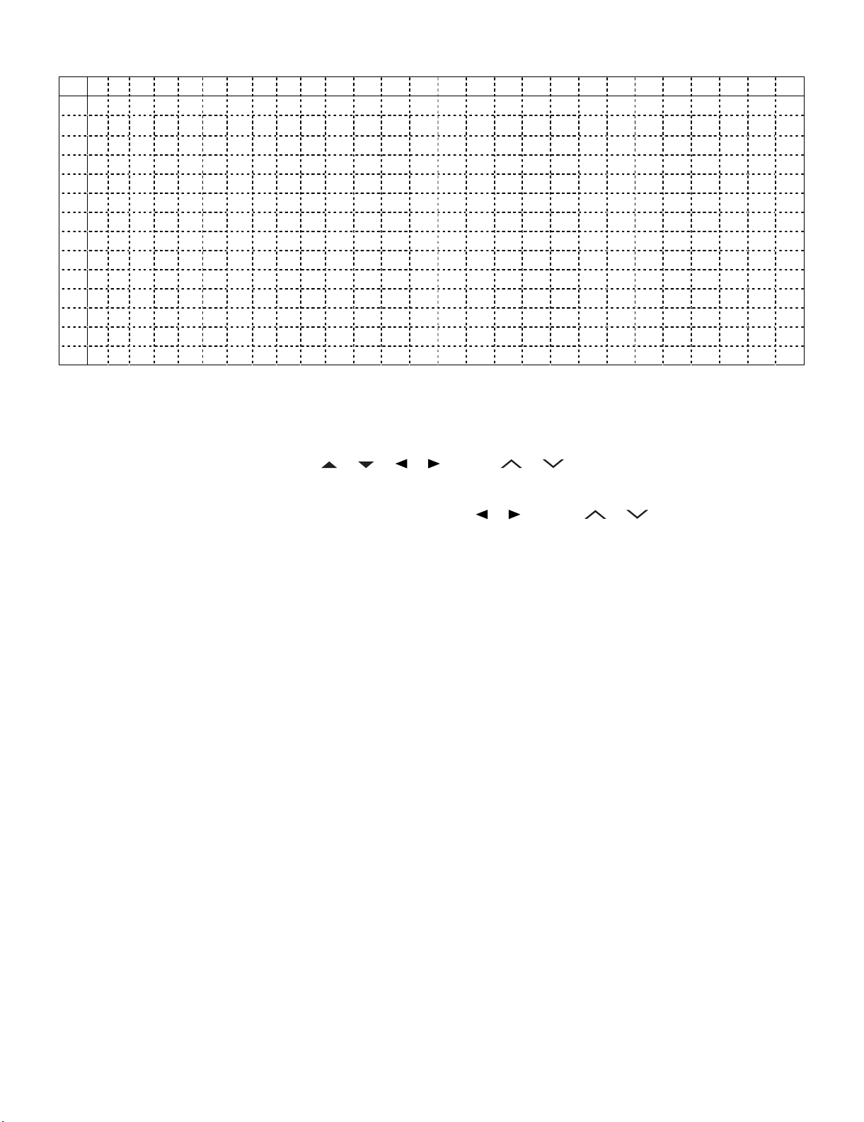
(Screen of adjustment process menu page 1)
012 3 4 5 6 7 8 9 1011121314151617181820212223242526
01
1M
2B
3I
4E
5P
6E
7P
8N
9E
10 11) 0 2) 0 3) 0
11 00H 0 M 0 H 0 M 0 H 0 M
12 44) 0 5) 0
13 00H 0 M 0 H 0 M
4. Adjusting the LCD panel
When replacing the LCD control PCB, follow these steps to adjust VCOM.
1. Enter the adjustment process mode.
O D E L A 6 5 4 M A
8 8 6 A H 0 0 4 - 0
N C H S I Z E 3 2
R R O R N O R E S E T 0
U B L I C M O D E O F F
X T C O N T R O L O F F
O W E R O N E R R O R C A U S E 0
O R M A L S T A N D B Y C A U S E 1
R R O R S T A N D B Y C A U S E
2. Select the item [VCOM ADJ] using the Cursor ( / / / ) or CH ( / ) keys on the remote controller.
3. Press the OK key to check that the adjustment pattern is displayed.
4. Adjust the flicker in the middle of the screen to minimum using the Cursor ( / ) or CH ( / ) or VOL (+)/(-) keys on the
remote controller.
5. Press the OK key to turn off the pattern.
6. To exit the adjustment process mode after the adjustment is done, unplug the AC cord from the outlet to make a forced shutdown. (When thepower was turned off with the remote controller, once unplug the AC cord and plug it again. In this case, wait 10 seconds or so before plugging.)
CAUTION: Use due care in handling the information described here lest your users should know how to enter the adjustment process mode.If the set-
tings are tampered in this mode, unrecoverable system damage may result.
5 – 2
Page 3
5. Adjustment
5.1. AD converter level adjustment
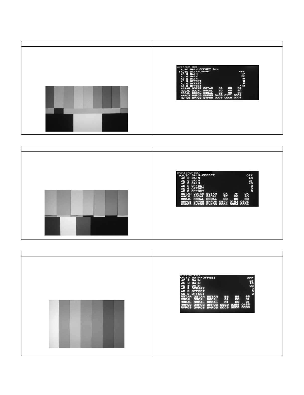
1. 1080i input
Adjustment Conditions Adjustment Procedure
1) 1080i 75% colour bar signal input
Used device name: LEADER LT448
Signal name: COLOUR BAR
* Use the LT-446-compatible third one of three color bars.
Setting value: 02: 1080i/59.94 (30 sF)
H: 33.72 kHz, V: 29.97 Hz
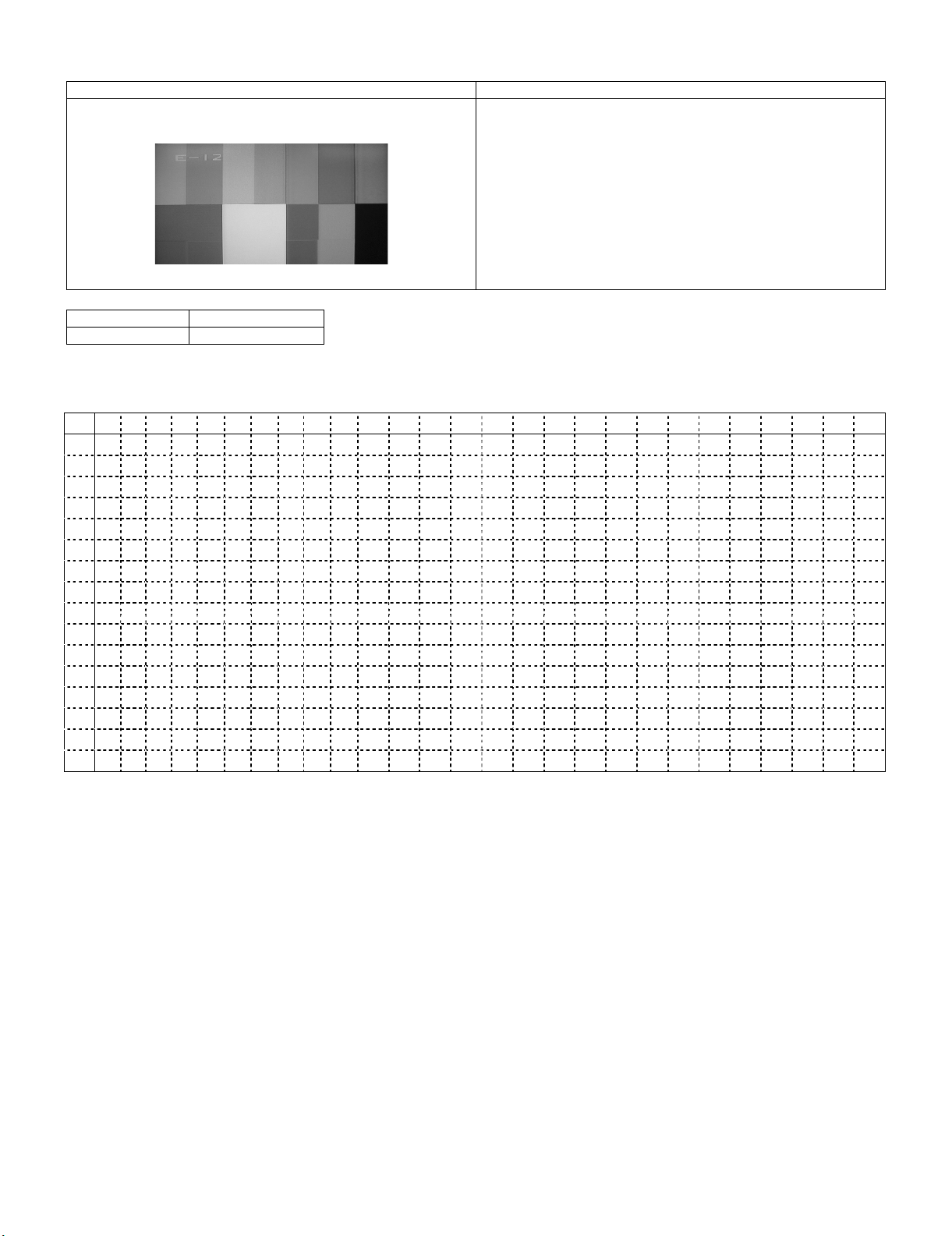
2. 480i input
Adjustment Conditions Adjustment Procedure
1) 480i 75% colour bar signal input
Used device name: LEADER LT448
Signal name: COLOUR BAR
* Use the LT-446-compatible third one of three color bars.
Setting value: 15: 480i/60
H: 15.73 kHz, V: 29.97 Hz
LC-32A33M
1) Set AUTO GAIN-OFFSET on page 3 (M2-HD) of the adjustment process DVP hierarchy to ON.
1) Set AUTO GAIN-OFFSET on page 4 (M2-SD) of the adjustment process DVP hierarchy to ON.
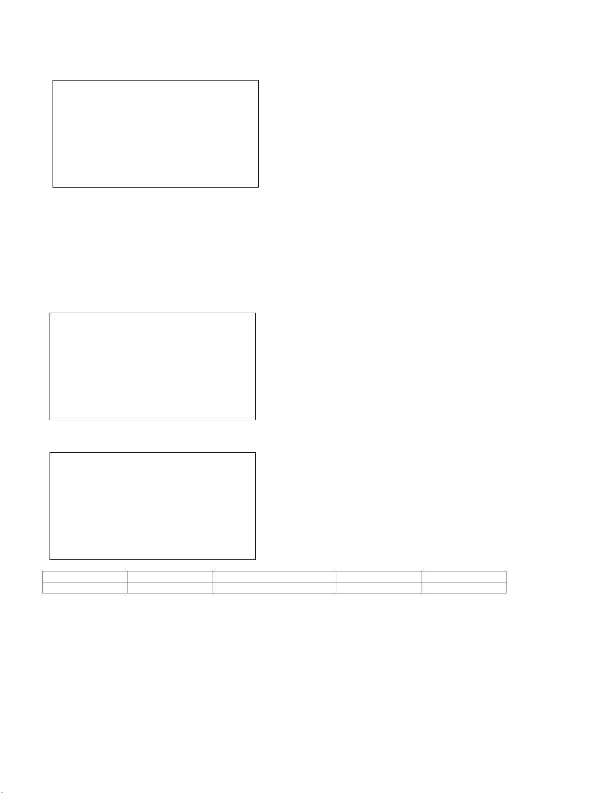
3. PC XGA input
Adjustment Conditions Adjustment Procedure
1) XGA 75% colour bar signal input (RGB)
Used device name: LEADER LT448
Signal name: COLOUR BAR “SATURATION 75%”
* Use one of two color bars where SATURATION can be changed.
Setting value: 28: XGA
H: 48.36 kHz, V: 60.00 Hz
Be sure to set the SYNC setting to OFF.
* If all the items are set to ON, “RUN” is displayed during adjustment.
1) Set AUTO GAIN-OFFSET on page 5 (M2-PC) of the adjustment process DVP hierarchy to ON.
5 – 3
Page 4
LC-32A33M
5.2. TAMP adjustment
Adjustment Conditions Adjustment Procedure
1) Receive the PAL standard colour bar signal. 1) If the maximum value of “PAL TAMP1” on page 1 of adjustment process DVP hierarchy is not in the range of values in the list below,
adjust “PAL TAMP1” on the same page so that the maximum value of
“Y” is in the range of values in the list below.
* Note that the setting value may vary by model.
2) When pressing the TAMP1 direct keys, adjustment of “PAL TAMP1”
is complete.
Then, The values of “NTSC TAMP1” and “SECAM TAMP1” are automatically set.
(NTSC: Value of PAL –7, SECAM: The same value as PAL)
MODEL LC-32A33M
Setting value 101 ~ 105
Reference
(Screen of page 1 of adjustment process menu DVP)
㩷 㪇㩷 㪈㩷 㪉㩷 㪊㩷 㪋㩷 㪌㩷 㪍 㪎㩷 㪏㩷 㪐㩷 㪈㪇 㪈㪈 㪈㪉 㪈㪊 㪈㪋 㪈㪌 㪈㪍 㪈㪎 㪈㪏 㪈㪐㩷 㪉㪇㩷 㪉㪈㩷 㪉㪉 㪉㪊 㪉㪋 㪉㪌 㪉㪍
㪇㩷 㪛㪛㩷 㪭㩷 㪧㩷 㪈㩷 㪄㩷 㪈㩷 㩷 㩷 㩷 㩷 㩷 㩷 㩷 㩷㩷㩷㩷㩷㩷㩷㩷㩷㩷㩷㩷㩷㩷
㪈㩷 㩷㩷㩷 㪭㩷 㪚㩷 㪦㩷 㪤㩷 㩷 㪘㩷 㪛㩷 㪡㩷 㩷 㩷 㩷 㩷㩷㩷㩷㩷㩷㩷㩷㩷㩷㩷 㩷 㪏㩷 㪊㩷 㩷
㪉㩷 㩷㩷㩷 㪫㩷 㪘㩷 㪤㩷 㪧㩷 㩷 㪈㩷 㪣㩷 㩷 㩷 㩷 㩷 㩷㩷㩷㩷㩷㩷㩷㩷㩷㩷㩷 㪈㩷 㪇㩷 㪈㩷 㩷
㪊㩷 㩷㩷㩷 㪰㩷 㪛㩷 㪘㩷 㪫㩷 㪘 㩷 㩷 㩷 㩷 㩷 㩷 㩷㩷㩷㩷㩷㩷㩷㩷㩷㩷㩷 㪈㩷 㪊㩷 㪉㩷 㩷
㪋㩷 㩷㩷㩷 㪫㩷 㪘㩷 㪤㩷 㪧㩷 㩷 㪈㩷 㪟㩷 㩷 㩷 㩷 㩷 㩷㩷㩷㩷㩷㩷㩷㩷㩷㩷㩷 㪈㩷 㪇㩷 㪌㩷 㩷
㪌㩷 㩷㩷㩷 㪫㩷 㪘㩷 㪤㩷 㪧㩷 㩷 㪘㩷 㪣㩷 㪣㩷 㩷 㩷 㩷 㩷㩷㩷㩷㩷㩷㩷㩷㩷㩷㩷 㪇㩷 㪝㩷 㪝㩷 㩷
㪍㩷 㩷㩷㩷 㪥㩷 㪫㩷 㪪㩷 㪚㩷 㩷 㪫㩷 㪘㩷 㪤㩷 㪧 㪈㩷 㩷 㩷㩷㩷㩷㩷㩷㩷㩷㩷㩷㩷 㩷 㪏㩷 㪊㩷 㩷
㪎㩷 㩷㩷㩷 㪧㩷 㪘㩷 㪣㩷 㩷 㪫 㪘㩷 㪤㩷 㪧㩷 㪈㩷 㩷 㩷 㩷㩷㩷㩷㩷㩷㩷㩷㩷㩷㩷 㩷 㪐㩷 㪇㩷 㩷
㪏㩷 㩷㩷㩷 㪪㩷 㪜㩷 㪚㩷 㪘㩷 㪤㩷 㩷 㪫㩷 㪘㩷 㪤 㪧 㪈㩷 㩷㩷㩷㩷㩷㩷㩷㩷㩷㩷㩷 㩷 㪐㩷 㪇㩷 㩷
㪐㩷 㩷㩷㩷 㩷 㩷 㩷 㩷 㩷 㩷 㩷 㩷 㩷 㩷 㩷 㩷㩷㩷㩷㩷㩷㩷㩷㩷㩷㩷 㩷 㩷㩷㩷
㪈㪇㩷 㩷㩷㩷 㩷 㩷 㩷 㩷 㩷 㩷 㩷 㩷 㩷 㩷 㩷 㩷㩷㩷㩷㩷㩷㩷㩷㩷㩷㩷 㩷 㩷㩷㩷
㪈㪈㩷 㩷㩷㩷 㩷 㩷 㩷 㩷 㩷 㩷 㩷 㩷 㩷 㩷 㩷 㩷㩷㩷㩷㩷㩷㩷㩷㩷㩷㩷 㩷 㩷㩷㩷
㪈㪉㩷 㩷㩷㩷 㩷 㩷 㩷 㩷 㩷 㩷 㩷 㩷 㩷 㩷 㩷 㩷㩷㩷㩷㩷㩷㩷㩷㩷㩷㩷 㩷 㩷㩷㩷
㪈㪊㩷 㩷 㩷 㩷㩷㩷 㩷 㩷 㩷 㩷 㩷 㩷 㩷 㩷 㩷 㩷㩷㩷㩷㩷㩷㩷㩷㩷㩷㩷㩷 㩷㩷㩷
㪈㪋㩷㩷㩷㩷㩷㩷㩷㩷㩷㩷㩷㩷㩷㩷㩷㩷㩷㩷㩷㩷㩷㩷㩷㩷㩷㩷㩷㩷
㪈㪌㩷㩷㩷㩷㩷㩷㩷㩷㩷㩷㩷㩷㩷㩷㩷㩷㩷㩷㩷㩷㩷㩷㩷㩷㩷㩷㩷㩷
5 – 4
Page 5

5.3. White balance adjustment
1. Place the luminance meter at the centre of the LCD screen
2. Set the LCD TV as below.
AV MODE : [STANDARD]
Backlight : +16(MAX)
Aging Time : Minimum 60 minutes
3. Adjustment Test Signal
[ Input Signal ] Display the WB built in test signal of RGB1 & RGB2 on the screen by using the remote control
code.(Key1 for RGB1, Key2 for RGB2)
[ Adjust Value ] Page 2-2 of adjustment process menu DVP : RGB 1 , RGB 2
✩Teaching set send by engineering dept is set as reference
4. Reference values for adjustment reference
( Equipment : Luminance meter [Minolta CA-210] )
Adjustment spec
RGB1 x = 0.261 ±0.004 ±0.01 radius from the center point
y = 0.277 ±0.004 ±0.01 radius from the center point
RGB2 x = 0.261 ±0.004 ±0.01 radius from the center point
y = 0.277 ±0.004 ±0.01 radius from the center point
*Initial value at RGB1 point : 800 ( G1 is fixed to 800 )
*Initial value at RGB2 point : 160 ( G2 is fixed to 160 )
Inspection spec
LC-32A33M
Ref. : For inspection, set the LCD TV as below.
AV MODE : [DYNAMIC]
Backlight : +16(MAX)
Aging Time : Minimum 60 minutes
5 – 5
Page 6
LC-32A33M
6. MCL setting procedure
1. “MCL” is displayed in the upper left portion of the screen as shown in the figure below by sending the MCL key of the remote control for adjustment.
㪤㪚㪣㩷
2. When the screen disappears after a few seconds and appears again, MCL setting is completed.
7. Factory setting
7.1. Performing the factory setting using the remote control for adjustment
1. Perform the factory setting using the remote control for adjustment. (This setting must be done after the MCL data setting.)
2. “M” stands for factory setting 2, “X” stands for factory setting 4 is displayed in the upper left portion of the screen by continuing to press the ‘Factory Setting’ key on the remote control for adjustment. (The figure below is the screen for factory setting 4.)
㪯㩷
3. When “SETTING COMPLETE” is displayed in the middle of the screen after a few seconds, setting is completed.
㪯㩷
㪪㪜㪫㪫㪠㪥㪞㩷㪚㪦㪤㪧㪣㪜㪫㪜㩷
Model name Key name Remote control code Setting S-SYSTEM Set OSD language
LC-32A33M Factory setting 2 100000001010110 B/G ENGLISH
4. Turn off the power.
NOTE: Set the Power switch to “OFF” immediately after completing the factory setting.
CAUTION: Do not plug on again after shipment setting is done. If do, please re-do the shipment setting. Do not power off with remote control.
5 – 6
Page 7
[2] PUBLIC MODE SETTING PROCEDURE
1. How to start Public Mode
• There are the following two ways to get the public mode setup screen displayed.
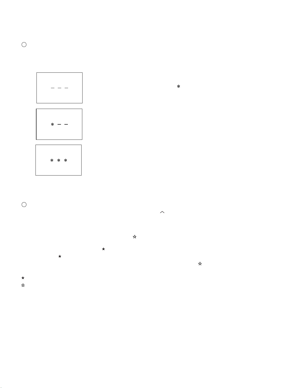
1
1) Press the “INPUT” and “VOL (+)” keys on the set at once and turn on the power.
2) Get the password input screen displayed.
Procedure
• The input starts with the leftmost digit.
• Use the numeric keys [1] thru [9] and [10/0] keys on the remote controller.
The other keys are not acceptable.
• With a numeric-key input, “–” will change to “ “. The input position will move one digit to the right.
• With all the 3 digits entered, the password will be verified.
LC-32A33M
3) The 3-digit password is now verified.
The password [0] [2] [7] provides for the public mode screen. (This screen comes on with whatever adjustment process settings.)
With any other passwords, the screen changes to the normal mode.
2
In the adjustment process mode, turn on “PUBLIC MODE”. Also press the “CH ( )” and “VOL (+)” keys on the set at once and turn on the power.
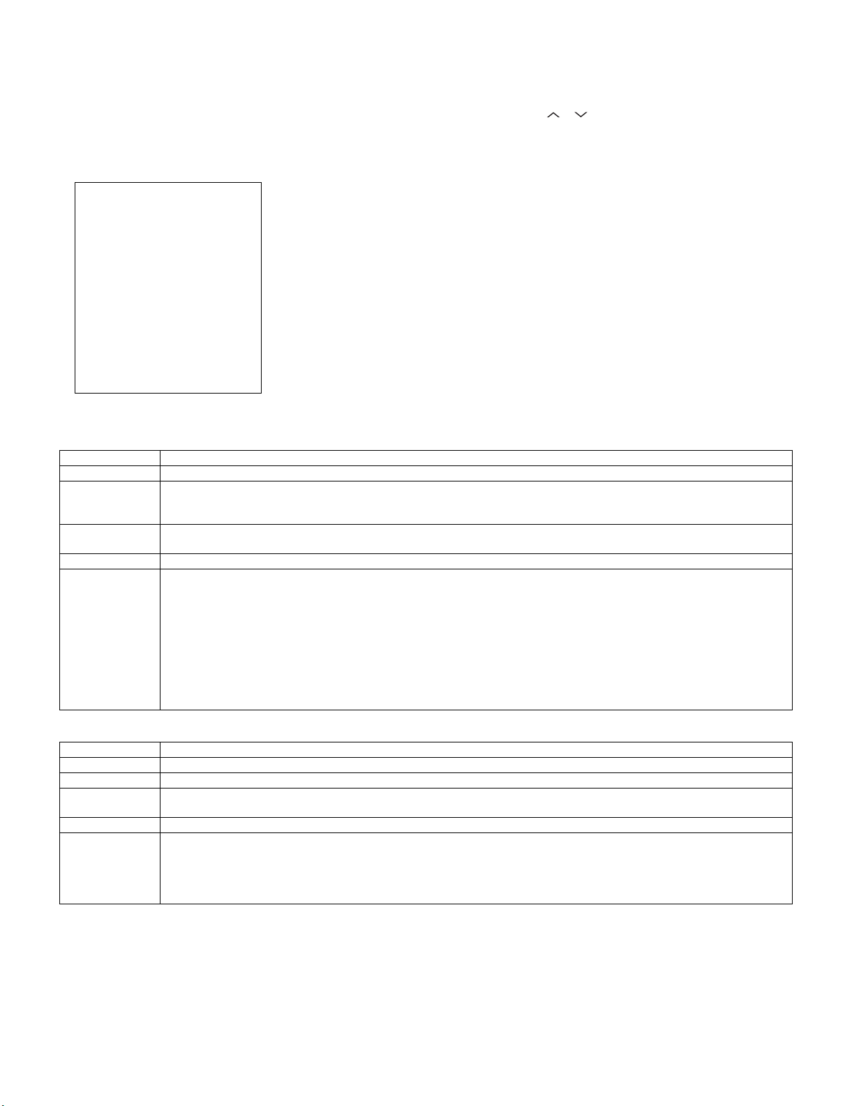
2. How to exit Public Mode
There are the following ways to quit the public mode setup screen.
• Turn off “PUBLIC MODE” in the adjustment process mode. ( ) ← This way alone is not for quitting the setup screen, but for quitting the mode
itself.
• Turn off the power with the “POWER” key. ( )
• Select “ENTER”. ( )
• Move the cursor to “RESET” and press the “FLASHBACK” key. (Back to the normal mode screen) ( )
••• “PUBLIC MODE” stays on in the adjustment process mode.
••• The settings will be back to the factory ones.
3. Public Mode Setting Values
• With the factory settings made, the public mode settings get initialized. (The adjustment process remains intact.)
5 – 7
Page 8
LC-32A33M
4. Public Mode Menu
The guidance is not displayed onscreen.
Setup procedure
• To move the cursor up and down, use the “cursor UP/DOWN” key (remote controller) and “CH ( )/( )” key (remote controller and set).
• To change the settings, use the “cursor RIGHT/LEFT” key (remote controller) and “VOL (+)/(–)” key (remote controller and set).
• To save new settings, keep the cursor at “Enter” and use the “cursor RIGHT/LEFT” key (remote controller) and “VOL (+)/(–)” key (remote controller
and set).
Public mode
Power on fixed
Maximum volume
Volume fixed
Volume fixed level
RC button
Panel button
Menu button
On screen display
Input mode start
Input mode fixed
232C Powon
RC path through
Reset
Enter
5. On Setting Items
1. POWER ON FIXED
[Variable ]
[ 60]
[Variable ]
[ 20]
[Respond ]
[Respond ]
[Respond ]
[Yes ]
[Normal ]
[Variable ]
[Disable ]
[Off ]
Selection Variable/Fixed
Default Variable
Explanation When set to “Fixed”, the power cannot be turned off with the power key on the remote control or main unit, and the image
reception state is kept (it does not enter the standby state).
The power can be turned off by shutting off power supply from AC.
Limit in setting • Power key on the main unit/remote control power supply key
• OFF timer/ON timer
Exception None
Remarks • Selection of “FIXED” assumes use of STB, etc.
• When set to “Variable”, if the main power switch is set to off, the power is turned off after a wait of 1 second.
(Push-push switch only)
• Display ON/OFF in the hotel menu is controlled by the adjustment process “HOTEL POWERFIX”.
• When the power button is operated, a caution is displayed (it times out in 5 seconds).
(For the caution, refer to the power on fixed message sheet.)
* The caution is not displayed when in the adjustment process, hotel menu, default setting, MCL operation and auto preset
(Ch search operation).
The OSD display including the menu and this caution have priority over all others.
When “OSD display” (described below) is set to “Variable”, this caution is displayed as a special case.
2. MAXIMUM VOLUME
Selection Adjustment from 1 to 60 (no loop)
Default 60
Explanation Sound volume can not be adjusted higher than the preset value.
Limit in setting • When the sound volume is set lower than 59, only figures are displayed and the sound volume bar is not displayed.
• The maximum sound volume for ON-timer (Wake up timer) is limited also to the preset value.
Exception • In the item “VOLUME” of adjustment process, the sound volume can be set freely irrespective of this setting.
Remarks • Setting is valid only for the speakers of the unit. (As for the headphone, the sound volume can be set up to 60 irrespective
of the limit.)
• In line output (sound volume variable), the sound volume can be adjusted from -60 to 0 irrespective of pre-adjusted value.
• When the sound volume is set higher than the MAX setting by the adjusting process or headphone, the sound volume con-
trol operation is prohibited for turn-up and the sound volume should be turned down to MAX in this state.
5 – 8
Page 9
LC-32A33M
3. VOLUME FIXED
Selection Selection between “Variable” and “Fixed” (loop provided)
Default Variable
Explanation Sound volume is fixed and made invariable.
Limit in setting • The sound volume for the ON-timer (Wake up timer) is fixed also without display of menu. Besides, the setting is made
Exception • In the item “VOLUME” of adjustment process, the sound volume can be set freely irrespective of this setting.
Remarks • In “Variable” setting, the sound volume had been conventionally set at 1 but this operation has been abolished (and follows
4. VOLUME FIXED LEVEL
Selection Adjustment from 1 to 60 (no loop)
Default 20
Explanation The sound volume to be fixed by “Volume fixed” is determined.
Limit in setting None
Exception None
Remarks Setting is valid only when “Volume fixed” is selected for “fixed”.
impossible. (Basically, the menu is not displayed.)
• The following keys become invalid:
1) Sound volume Up/Down (VOL +/-) [for both remote control and the unit]
2) Mute (MUTE)
the last memory).
• The sound volume for the ON-time is not set at 1 either and the sound volume set value of the ON-timer before executing
the hotel mode is held.
• Setting is valid only for the speakers of the unit. (As for the headphone, the sound volume can be set up to 60 irrespective
of the limit.)
• In line output (sound volume variable), the sound volume can be adjusted from -60 to 0 irrespective of pre-adjusted value.
• As for sound volume fixing and sound volume MAX level, the sound volume fixing has priority.
• Once the sound volume has been changed by adjustment process or headphone, it should be set back to the sound volume
preset by sound volume fixing level when the adjustment process ends or when the headphone is removed.
This must be confirmed actually by changing also the sound volume in accordance with setting.
5. R/C BUTTON
Selection Selection between “Respond”, “Limited” and “No respond” (loop provide)
Default Respond
Explanation Keys acceptable by remote control are limited or reception of keys can be prohibited.
Limit in setting 1) In “limited” setting, only power ON/OFF, sound volume , tuning and BACKLIGHT (brightness sensor) are
accepted.
2) In “No respond” setting, all the keys (including the power key) are not accepted.
Exception • Adjustment process, factory setting, inspection process and hotel only keys are valid irrespective of setting.
Remarks
6. PANEL BUTTON
Selection Selection between “Respond” and “No respond” (loop provide)
Default Respond
Explanation All the operations by keys (except the power key) of the unit can be invalidated.
Limit in setting
Exception • Inspection mode and hotel menu mode can be started irrespective of setting.
Remarks
7. MENU BUTTON
Selection Selection between “Respond” and “No respond” (loop provide)
Default Respond
Explanation In “No respond” setting, the menu operation by the menu key of the remote control and the menu key of the unit are invali-
Limit in setting • ON-timer (Wakeup Timer) is turned OFF.
Exception • Inspection mode and hotel menu mode can be started irrespective of setting.
Remarks
• All the keys can be used in adjustment process, inspection mode and hotel menu irrespective of setting.
• All the keys can be used in adjustment process, inspection mode and hotel menu irrespective of setting.
dated.
• The following keys become invalid.
Wake-up timer and clock setting keys and all of the direct change keys to menu display
• All the keys can be used in adjustment process, inspection mode and hotel menu irrespective of setting.
5 – 9
Page 10
LC-32A33M
8. ON SCREEN DISPLAY
Selection Selection between “Yes”, “Limited” (loop provide)
Default Yes
Explanation The following OSD displays are made ineffective.
Displays of menu group, channel call, sound volume bar and direct key call
Limit in setting • Set time of the OFF-timer (SLEEP TIMER) is cleared.
• Setting of the no-signal power-OFF (AUTO POWER OFF) is cleared to “OFF”.
• Setting of the no-operation power-OFF is cleared to “OFF”.
• Keys falling under any of the following items become invalid.
1) Appearance of screen changes and the sound changes.
2) Personal functions which are hard to restore.
Ex.) Screen display, menu, OFF-timer, ON-timer, AV MODE, screen size switching, clock setting, treble emphasis, AUDIO
ONLY, sound changeover, LANGUAGE, CLOSED CAPTION
Others • Simple input switching is generated. Those which are restored soon after leaving as they are and may be requested for
change by customer are not prohibited.
Ex.) Brightness sensor (BACKLIGHT) and PIC. FLIP
Exception • Such a caution which is displayed independently is displayed as it is.
9. INPUT MODE START
Selection Selection between “Normal”, “TV (CH~)” “INPUT1~5”, “PC” (loop provide)
Default Normal
Explanation In power-ON, the input source to be started or channel can be set.
About options • All the input sources in the model are made selectable.
Limit in setting • The display of channel setting menu and the channel setting operation are prohibited (except for MCL).
Exception None
Remarks • In setting at “Normal”, the setting of “Input mode fixed” is changed to “Variable” and selection should be prohibited.
10.INPUT MODE FIXED
Selection Selection between “Variable” and “Fixed” (loop provide)
Default – (Variable)
Explanation The input mode is fixed at the input source or the channel set at the “Input mode start” in 9 and other input sources and chan-
Limit in setting • With the execution of hotel mode, the input source is forced to change to that set by “Input mode start” and the channel
Exception None
Remarks • In the following case, setting is cancelled and mode is changed to “Variable”.
11.232C POWON
Non-responding signal caution, TELETEXT caution and power-ON fixing caution
(In standard mode, the operation follows the last memory.)
• When the input/output switchable input source is selected and the input source is set to output, the setting of input/output
switching is changed to input at the execution of hotel menu. In addition, the input/output switching by menu is prohibited.
• In TV mode, the display of all channels is stopped and it is treated as an input source. At this time, the channel to be set fol-
lows the last memory and the content of the last memory is included in the notation by options. Ex.) TV (CH2), TV (CH4)
etc.
• The order of appearance of options in the hotel menu should agree with the order of toggles by input switching key.
nels can be made non-selectable.
switching and input switching are prohibited thereafter.
• The following keys are invalidated.
CH , direct tuning button, FLASHBACK, input
*However, the keys (input switching and CH keys) of the unit for menu operation remain valid.
1
When the setting of “Input mode start” is set to “Standard (Normal)”
Selection “Enable” and “Disable”
Default Disable
Explanation When in the standby state, power ON by the RS-232C command is enabled or disabled.
Limit in setting None
Exception None
Remarks It is irrelevant to power OFF by the RS-232C command.
5 – 10
Page 11

LC-32A33M
12.RC PATH THROUGH
Selection “Off”, “On: TV RCE”, “On: TV RCD”
Default Off
Explanation Remote control signal output from the pin 9 of the RS-232C terminal and signal reception by is enabled or disabled.
When set to “ON: TV RCE”, TV also receives signals. With “ON: TV RCD”, the remote control signal is output from the pin 9,
but TV does not respond to the remote control.
Limit in setting When set to “ON: TV RCD”, TV does not accept the remote control.
Exception None
Remarks
RS-232C power ON command “POWR1_ _ _ ”
5 – 11
Page 12
㪆
㪣
㪩
㪣
㪫
㪫
LC32AA3M
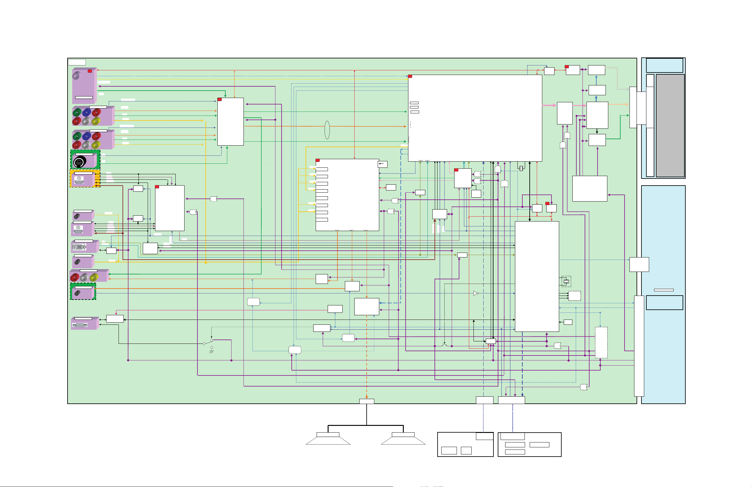
CHAPTER 7. BLOCK DIAGRAM/OVERALL WIRING DIAGRAM
[1] BLOCK DIAGRAM
LC-32A33M
Service Manual
㩷
㪤㪘㪠㪥
㪫㪬㪥㪜㪩
㪤㫆㪻㫌㫃㪼
㪫㪬㪊㪋㪇㪉
㪭㪫㪬㪭㪫㪉㪮㪏㪚㪛㪌㪌
㪨㪪㪦㪚㪛㪘㪇㪊㪌㪮㪡㪱
㪨㪪㪦㪚㪱㪘㪈㪊㪍㪮㪡㪱㪱
㪨㪡㪘㪢㪡㪇㪇㪇㪏㪞㪜㪱㪱
㪨㪪㪦㪚㪱㪘㪈㪊㪍㪮㪡㪱㪱
㪨㪪㪦㪚㪥㪘㪎㪈㪍㪮㪡㪱㪱
㪨㪡㪘㪢㪡㪇㪇㪇㪏㪞㪜㪱㪱
㪨㪡㪘㪢㪞㪘㪈㪊㪉㪮㪡㪨
㪨㪡㪘㪢㪡㪘㪇㪈㪋㪮㪡㪱
㪨㪪㪦㪚㪥㪘㪎㪈㪌㪮㪡㪱
㪠㪥㪧㪬㪫㪌
㪟㪛㪤㪠㩷㪠㪥
㪪㪚㪋㪇㪋
㪠㪥㪧㪬㪫㪊
㪘㪬㪛㪠㪦㩷㪠㪥
㪠㪥㪧㪬㪫㪋
㪟㪛㪤㪠㩷㪠㪥
㪪㪚㪋㪇㪊
㪘㪥㪘㪣㪦㪞㪬㪜
㪠㪥㪧㪬㪫㪍
㪘㪬㪛㪠㪦㩷㪠㪥
㪟㪧㩷㪡㪘㪚㪢
㪠㪉
㪨㪡㪘㪢㪣㪘㪇㪊㪎㪮㪡㪨
㪨㪡㪘㪢㪣㪘㪇㪊㪎㪮㪡㪨
㪠㪥㪧㪬㪫㪉
㪡㪊㪋㪇㪈
㪪㪰㪆㪪㪚
㪟㪛㪤㪠
㪠㪥㪧㪬㪫㪍
㪩㪞㪙㩿㪧㪚㪀
㪪㪚㪋㪇㪈
㪧㪚
㪡㪋㪇㪌
㪡㪋㪇㪍
㪩㪪㪄㪉㪊㪉㪚
㪪㪚㪈㪐㪇㪈
㪪㪛㪘㪈
㪪㪚㪣㪈
㪪㪶㪠㪝㵘㩿㪘㫅㪸㫃㫆㪾㪀
㪚㪭㪙㪪
㪠㪥㪧㪬㪫㩷㪈
㪚㪦㪤㪧㪦㪥㪜㪥㪫
㪠㪥㪧㪬㪫㩷㪉
㪚㪦㪤㪧㪦㪥㪜㪥㪫
㪪㪪㪮
㪰㪆㪚
㪣㪆㪩㪶㪟㪛㪤㪠
㪟㪃㪭
㪧㪚㩷㪶㪩㪞㪙
㪦㪬㪫㪧㪬㪫
㪡㪊㪋㪇㪉
㪚㪭㪙㪪
㪟㪧㪶㪛㪜㪫
㪙㪌㪭
㪡㪊㪋㪇㪊
㪚㪭㪙㪪
㪡㪊㪋㪇㪋
㪚㪭㪙㪪
㪛㪛㪚㪈
㪫㪤㪛㪪㪈
㪟㪧㪛㪈㪶㪠㪥
㪚㪜㪚㩷㪣㪠㪥㪜
㪛㪛㪚㪉
㪫㪤㪛㪪㪉
㪟㪧㪛㪉㪶㪠㪥
㪚㪜㪚㩷㪣㪠㪥㪜
㪟㪛㪧㪶㪚㪫㪣㪉
㪜㪜㪧㪩㪦㪤
㪪㪉㪋㪚㪪㪇㪉㪡
㪠㪚㪋㪇㪈
㪣㪆㪩㪶㪧㪚
㪩㪪㪄㪉㪊㪉㪚㩷㪫㫏㪆㪩㫏
㪠㪪㪣㪏㪊㪉㪉㪇
㪛㪜㪫㪈㩿㪚㪭㪙㪪㪆㪚㪦㪤㪧
㪰㪃㪧㪹㪃㪧㫉
㪚㪭㪙㪪
㪣㪆㪩㪶㪘㪭㪈
㪛㪜㪫㪉㩿㪚㪭㪙㪪㪆㪚㪦㪤㪧
㪰㪃㪧㪹㪃㪧㫉
㪚㪭㪙㪪
㪣㪆㪩㪶㪘㪭㪉
㪜㪜㪧㪩㪦㪤
㪪㪉㪋㪚㪪㪇㪉㪡
㪠㪚㪋㪇㪍
㪜㪜㪧㪩㪦㪤
㪪㪉㪋㪚㪪㪇㪉㪡
㪠㪚㪋㪇㪋
㪧㪘㪥㪜㪣㪶㪧㪦㪮
㪭㪚㪦㪤㪶㪪㪛㪘
㪜㪜㪧㪩㪦㪤
㪠㪉
㪭㪚㪦㪤㪶㪪㪚㪣
㪙㪬㪪㩷㪪㪮
㪛㪭㪧㪶㪩㪜㪨㪆㪠㪥㪫㪆㪫㪯㪛㪆㪩㪯㪛
㪙㪬㪪㩷㪪㪮
㪫㪚㪎㪮㪍㪍㪬
㪠㪚㪉㪇㪇㪉
㪚㪧㪬
㪠㪚㪉㪇㪇㪈
㪫㪚㪎㪮㪍㪍㪬
㪠㪚㪉㪊㪇㪉
㪣㪭㪛㪪
㪠㪉㪚㩿㪇㪀
㪪㪛㪘㪉
㪪㪚㪣㪉
㪠㪉
㪜㪜㪧㪩㪦㪤
㪪㪉㪋㪚㪪㪍㪋
㪙㪬㪊㪅㪊㪭
㪪㪛㪘㪈
㪠㪩㪜㪤
㩿㪩㪆㪚㪀
㪦㪧㪚
㪪㪚㪣㪈
㪉㪎㪤㪟䌺
㫏㫋㪸㫃
㪛㪭㪧㪊㪊㪶㪚㪫㪩
㪤㪘㪠㪥㪶㪪㪮
㪩㪟㪄㪠㪯㪚㪈㪏㪉㪮㪡㪨㪈㪨
㪟㪧㪶㪛㪜㪫
㪠㪩㪜㪤㪶㪪㪮
㪠㪩㪜㪤
㪘㪝㪫
㪠㪉
㪟㪛㪤㪠㩷㪪㪮㪠㪫㪚㪟
㪠㪚㪈㪌㪇㪎
㪭㪟㪠㪪㪠㪠㪐㪈㪏㪌㪂㪄㪈㪨
㪠㪉
㪭㫀㪻㪼㫆㩷㪪㪮
㪩㪜㪥㪜㪪㪘㪪
㪩㪉㪘㪈㪈㪇㪈㪈㪝㪧
㪊㪅㪊㪭
㪩㪜㪞
㪈㪅㪌㪭
㪩㪜㪞
㪙㪐㪭
㪙㪌㪭
㪣㪆㪩㪶㪘㪭㪈
㪣㪆㪩㪶㪘㪭㪉
㪣㪆㪩㪶㪘㪭㪊
㪣㪆㪩㪶㪘㪭㪈
㪣㪆㪩㪶㪟㪛㪤㪠
㪣㪆㪩㪶㪧㪚
㪠㪉
㪠㪥㪧㪬㪫㪈㩷㪣㪆㪩
㪠㪥㪧㪬㪫㪉㩷㪣㪆㪩
㪠㪥㪧㪬㪫㪊㩷㪣㪆㪩
㪠㪥㪧㪬㪫㪋㩷㪣㪆㪩
㪠㪥㪧㪬㪫㪌㩷㪣㪆㪩
㪠㪥㪧㪬㪫㪍㩷㪣㪆㪩
㪠㪥㪧㪬㪫㪎㩷㪣㪆㪩
㪰
㪧
㪹
㪧
㫉
㪭㫆㫃㫌㫄㪼㪆㪜㪨㪆㪪㫌㫉㫉㫆㫌㫅㪻㵘㪪㪮
㪠㪚㪊㪍㪇㪉
㪘㫌㪻㫀㫆
㪫㪘㪪㪊㪉㪇㪏㪛
㪪㪛㪘㪈
㪪㪚㪣㪈
㪠㪉㪚㪈
㪉㪋㪅㪌㪎㪍㪤㪟䌺
㫏㫋㪸㫃
㫧㪊㪇㫇㫇㫄
㪜㪜㪧㪩㪦㪤
㪠㪉㪚㪉
㪠㪯㪚㪉㪌㪈㪮㪡
㪠㪚㪊㪍㪇㪊
㪊㪅㪊㪭
㪐㪭
㪩㪜㪞
㪠㪥㪧㪬㪫㪏㩷㪣㪆㪩
㪪㪧㪛㪠㪝
㪛㪘㪚㪦㪬㪫㪉
㪛㪘㪚㪦㪬㪫㪉
㪟㪧㪦㪬㪫㪣
㪤㪬㪫㪜㪶㪜㪥
㪙㪌㪭
㪘㪬㪛㪠㪦㩷㪘㪤㪧
㪠㪚㪈㪊㪇㪈
㪰㪛㪘㪈㪋㪎㪪㪱
㪟㪧㪦㪬㪫㪩
㪪㪪㪫㪙㪰㪃㪘㪤㪧㪶㪟㪦㪞㪦
㪙㪬㪝㪝㪜㪩
㪣㪚㪯㪈㪉㪌㪝㪫
㪠㪚㪈㪌㪇㪈
㪮㪧㪶㪚㪦㪥㪫
㪚㪜㪚㪶㪠㪥
㪚㪜㪚㪶㪦㪬㪫
㪫㪤㪛㪪
㪟㪛㪤㪠㪶㪩㪪㪫
㪐㪭
㪥㪡㪤㪉㪎㪋㪍㪭㪄㪈㪰
㪦㪬㪫㪧㪬㪫㩷㪘㪤㪧
MUTE
Circuit
MUTE
Circuit
㪠㪚㪊㪍㪇㪈
䋲䋳䋲㪚㪶㪧㪦㪮
㪠㪩㩷㪧㪸㫊㫊㩷㪪㪮
㪫㪚㪎㪪㪟㪇㪇㪬
㪧㫆㫎㪼㫉㵘㪪㪮
㪩㪪㪉㪊㪉㪚
㪠㪩㪜㪤㪶㪪㪮
㪠㪩㪜㪤㩿㪩㪆㪚㪀
MUTE
Circuit
㪙㪟㪊㪌㪋㪋㪝
㪟㪧㩷㪘㪤㪧
㪠㪚㪊㪍㪇㪋
㪘㪬㪤㪬㪫㪜
㪊㪅㪊㪭
㪩㪜㪞
㪚㪭㪙㪪㪆㪘㪫
㪪㪩㪜㪪㪜㪫
㪪㪧㪛㪠㪝
㪙㪊㪅㪊㪭㪶㪪㪬㪙
㪈㪊㫍
㪰㪧㪹㪧㫉
㪰㪆㪚
㪣㪆㪩㪶㪘㪭㪈
㪠㪉
㪥㪈㩷㩿㪭㪠㪥㪈㪙㪀
㪢㪉㩷㩿㪭㪠㪥㪌㪘㪀
㪬㪉㩷㩿㪭㪠㪥㪈㪚㪀
㪘㪤㪧㪶㪟㪦㪞㪦
㪪㪪㪫㪙㪰
㪣㪶㪤㪬㪫㪜
㪟㪧㪶㪤㪬㪫㪜
㪡㪈㩿㪭㪠㪥㪈㪘㪀㪔㩷㪧㪹
㪥㪉㩿㪭㪠㪥㪌㪙㪀㩷㪔㩷㪧㫉
㪮㪈㩿㪭㪠㪥㪋㪚㪀㩷㪔㩷㪰
㪢㪈㩿㪭㪠㪥㪉㪚㪀㩷㪔㩷㪚
㪧㪈㩿㪭㪠㪥㪉㪙㪀㩷㪔㩷㪰
㪟㪃㪭
㪪㪩㪜㪪㪜㪫
㪪㪺㪿㫄㫀㫋㫋
㪠㪚
㪪㪠㪝
㪪㪧㪶㪤㪬㪫㪜
㪧㪚㪟㪛㪠㪥
㪧㪚㪭㪛㪠㪥
㪟㪛㪧㪶㪚㪫㪣㪈㪤
㪟㪛㪧㪶㪚㪫㪣㪉㪤
㪙㪬㪝㪝㪜㪩
㪣㪚㪯㪈㪉㪌㪝㪫
㪠㪚㪈㪌㪇㪈
㪟㪛㪧㪶㪚㪫㪣㪈㪆㪉
㪊㪅㪊㪭㪘
㪠㪩㪜㪤㩿㪶㪠㪥
㪠㪩㪜㪤㩿㪩㪆㪚㪀
㪙㪄㪺㪿㩷㩿㪭㪠㪥㪋㪙㪀㩷㪔㩷㪧㪚㪶㪩
㪘㪄㪺㪿㩷㩿㪭㪠㪥㪋㪘㪀㩷㪔㩷㪧㪚㪶㪙
㪚㪄㪺㪿㩷㩿㪭㪠㪥㪊㪚㪀㩷㪔㩷㪧㪚㪶㪞
㪘㪛㪶㪠㪥㪫㪈
㪧㪚㪶㪩㪆㪞㪆㪙
㪘㪛㪶㪠㪥㪫
㪛㪭㪧㪄㪤㪉
㪩㪟㪄㪠㪯㪙㪏㪏㪍㪮㪡㪱㪱㪨
㪠㪉㪪
㪠㪉
㪟㪛㪤㪠㩷㪩㪼㪺㫀㪼㫍㪼㫉
㪤㪪㪫㪊㪊㪏㪊㪘
㪠㪚㪏㪎㪇㪉
㪊㪅㪊㪭㩷㪉㪊㪌㫄㪘
㪉㪅㪌㪭㩷㪈㪈㪏㫄㪘
㪫㪤㪛㪪
㪘㪛㪠㪥㪫
㪘㪛㪶㪩㪜㪪㪜㪫
㪙㪬㪊㪅㪊㪭
㪪㪺㪿㫄㫀㫋㫋
㪠㪚
㪟㪃㪭㪃
㪛㪜㪃㪚㪣㪢
㪠㪚㪏㪇㪈
㪈㪋㪅㪊㪈㪏㪤㪟䌺
㫏㫋㪸㫃
㫧㪊㪇㫇㫇㫄
㪢㪜㪰㪈
㪢㪜㪰㪉
㪪㪫㪙㪰㪶㪧㪦㪮
㪊㪅㪊㪭
㪩㪜㪞
㪉㪅㪌㪭
㪩㪜㪞
㪫㫏㪛㪆㪩㫏㪛
㪠㪩㪜㪤㪶㪪㪮
䋨㪮㪪㪊䋩
Rewriting
Connector
㪡㪫㪘㪞
㪊㪅㪊㪭
㪩㪜㪞
㪛㪛㪚㪩㪜㪪㪜
㪈㪅㪌㪭
㪩㪜㪞
㪪㪛㪘㪉㪶㪙㪬
㪪㪚㪣㪉㪶㪙㪬
㪡㪫㪘㪞
㪛㪛㪚㪩㪜㪪㪜
㪪㪶㪠㪝
㪚㪦㪤㩷㪘㪛㪡
㪙㪬㪌㪌㪇㪋㪈㪟㪝㪥
㪠㪚㪏㪉㪇㪉
㪠㪉㪚㩿㪇㪀
㪣㪭㪛㪪
㪭㪚㪚㪶㪈㪅㪌㪭
㪭㪚㪚㪉㪅㪌㪭
㩷㩷㩷㩷㩷㪛㪚㪛㪚㩷㪠㪚
㩷㩷㩷㩷㩷㪠㪚㪏㪋㪇㪉
㩷㩷㩷㩷㩷㪙㪛㪏㪈㪍㪉㪜㪢
㩷㩷㩷㩷㩷㩷㩷㪫㪄㪚㪦㪥
㩷㩷㩷㩷㩷㩷㩷㪠㪚㪏㪈㪇㪊
㩷㩷㩷㩷㩷㩷㩷㪫㪊㪱㪈㪏㪘㪝㪞
㪭㪚㪚㪶㪊㪅㪊㪭
㪚㪦㪣㪦㪩
㪤㪘㪥㪘㪞㪜㪤㪜㪥㪫
㪠㪚㪋㪉㪇㪈
㪠㪯㪭㪊㪇㪇
㪊㪅㪊㪭
㪩㪜㪞
㪈㪅㪏㪭
㪩㪜㪞
㪘
㪣㪶㪜㪩㪩
㪧㪪㪠㪱㪶㪣㪆㪟
㪠㫅㪺㪿㩷㪪㫀㫑㪼
㪘㪩㪜㪘㪈㪆㪊
㪪㪼㫃㪼㪺㫋
㪜㪩㪩㪦㪩㪦㪝㪝
㪚㫀㫉㪺㫌㫀㫋
㪘㪚㪶㪚㪫㪣
㪘㪚㪶㪛㪜㪫 㪘㪚㪶㪛㪜㪫
㪧㪦㪮
㪩㪜㪪㪜㪫
㪠㪚㪉㪇㪇㪍
㪙㪌㪭
㪊㪅㪊㪭
㪩㪜㪞
㪙㪋㪭
㪙㪉㪅㪎㪭
㪙㪬㪌㪭
㪠㪚㪏㪋㪇㪊
㪫㪙㪍㪏㪈㪌㪝㪞
㪣㪼㪹㪼㫃㩷㪪㪿㫀㪽㫋㩷㪠㪚
㪘㪪㪠㪚㪶㪚㪪㪈䌾㪍
㪠㪚㪏㪋㪇㪋
㪠㪯㪙㪋㪉㪇㪮㪡
Multi Pixel IC
㪞㪘㪞㪚㪢㪃㪞㪪㪧㪈㪃㪉
㪬㪆㪛㪃㪩㪜㪘㪛㪰㪃㪩㪜㪪㪜㪫
㪛㪘㪚㪶㪚㪣㪢㪃㪛㪘㪫㪘㪃㪣㪘㪫㪚㪟
㪞㫉㪸㪻㪸㫋㫀㫆㫅㩷㪠㪚
㪠㪚㪏㪉㪇㪈
㪙㪛㪏㪈㪋㪊㪤㪬㪭
㪙㪌㪭
㪛㪚㩷㪛㪚
㪚㫀㫉㪺㫌㫀㫋
㪙㪋㪭
㪙㪉㪅㪎㪭
㪙㪈㪊㪭
㪙㪈㪊㪭㪈㪘
㪭㪣㪪㪈㪌㪅㪍㪭
㪚㪪㪈㫕㪈㪉
㪭㪣㪇䌾㪉㪌㪌㪃
㪭㪟㪇䌾㪉㪋㪎
㪘㪚㪶㪚㪫㪣
㪩㪪㪛㪪
㪩㪪㪛㪪
㪚㪦㪥㪥㪜㪚㪫㪜㪩
㪠㪥㪭㪜㪩㪫㪜㪩
㪚㪦㪥㪥㪜㪚㪫㪜㪩
㪧㪥㪣㪶㪈㪊㪭
㪙㪬㪌㪭
㪈㪊㪭
㪣㪚㪛㩷㪤㪦㪛㪬㪣㪜
㪩㪪㪛㪪
㪩㪪㪛㪪
㪚㪦㪥㪥㪜㪚㪫㪜㪩
㪧㪦㪮㪜㪩㩷㪤㪦㪛㪬㪣㪜
㪧㪦㪮㪜㪩㩷㪚㪦㪥㪥㪜㪚㪫㪦㪩
㪣㪚㪛㩷㪧㪘㪥㪜㪣
㪠㪥㪭㪜㪩㪫㪜㪩
㪊㪅㪊㪭
㪣㪜㪛㪶㪦㪧㪚
㪧㪌㪉㪇㪋
㪧㪈㪊㪇㪈㩷㪥㪘㪈㪎㪊㪮㪡
㪋㫇㫀㫅
㪪㪧㪪㪧
7 – 1
㪦㪧㪜㪩㪘㪫㪠㪦㪥
㪚㪦㪥㪫㪩㪦㪣㩷㪪㪮
㪪㪈㪌㪈㪄㪈㪌㪍
㪧㪦㪮㩷㪪㪮
㪥㪘㪊㪉㪋㪮㪡
㪋㫇㫀㫅
㪢㪜㪰㪈
㪢㪜㪰㪉
㪪㪫㪙㪰㪶㪧㪦㪮
㪞㪥㪛
㪧㪈㪌㪈
㪨㪧㪣㪞㪥㪘㪇㪌㪐㪮㪡㪱㪱
㪋㫇㫀㫅
㪪㪈㪌㪎
㪊㪅㪊㪭㪘
㪧㪌㪉㪇㪊
㪥㪘㪊㪊㪊㪮㪡
㪈㪊㫇㫀㫅
㪙㪬㪂㪊㪅㪊㪭
㪦㪧㪚㪂㪊㪅㪊㪭
㪞㪥㪛
㪩㪆㪚
㪧㪦㪮㪞㪶㪣㪜㪛
㪧㪦㪮㪩㪶㪣㪜㪛
㪣㪜㪛㪶㪦㪧㪚
㪞㪥㪛
㪧㪈㪇㪈
㪨㪧㪣㪞㪥㪘㪊㪊㪌㪮㪡㪱㪱㪰
㪏㫇㫀㫅
㪦㪧㪚
㪠㪚㪈㪇㪈
㪣㪜㪛
㪛㪈㪇㪊㪆㪈㪈㪌
㪣㪜㪛㪶㪞㪆㪣㪜㪛㪶㪩
㪣㪜㪛
㪠㪩㩷㪩㪼㪺㫀㪼㫍㪼㫉
㪩㪤㪚㪈㪇㪈
㪩㪜㪞
Page 13
LC-32A33M
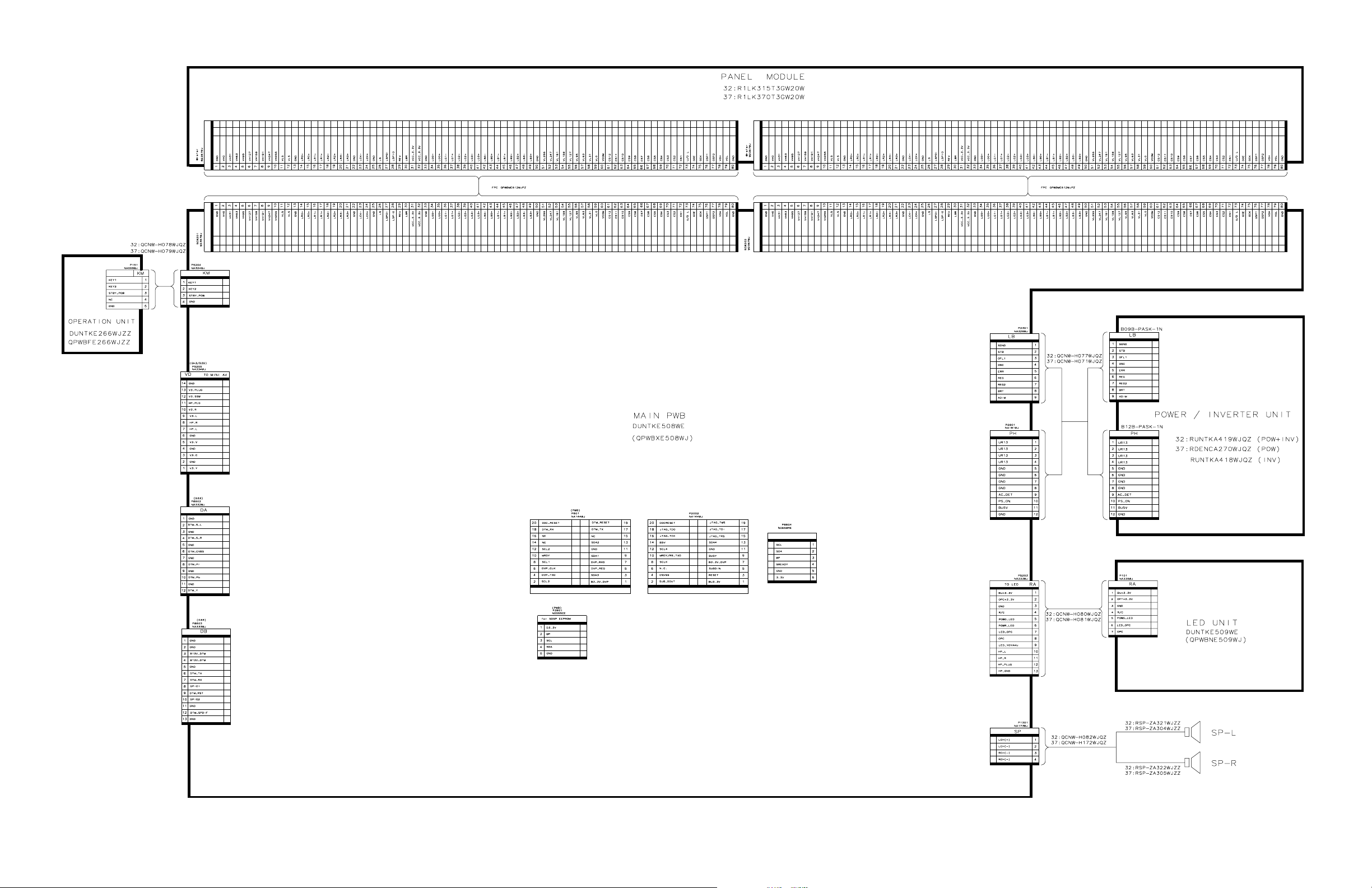
[2] OVERALL WIRING DIAGRAM
7 – 2
Page 14
LC32AA3M
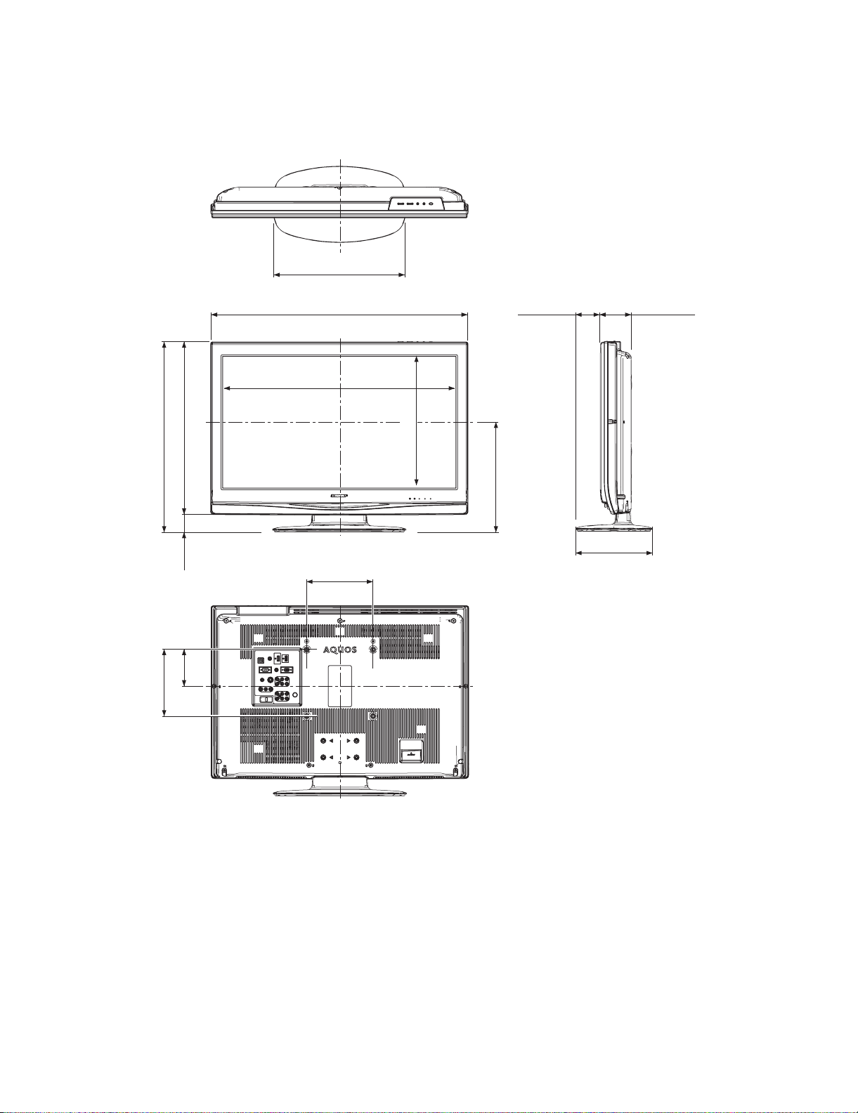
CHAPTER 3. DIMENSIONS
[1] DIMENSIONS
LC-32A33M
Service Manual
Unit: mm
402
578
200
52355
110
701.5
776
200
74 95
395.9
335
230
3 – 1
Page 15
LC32AA3M
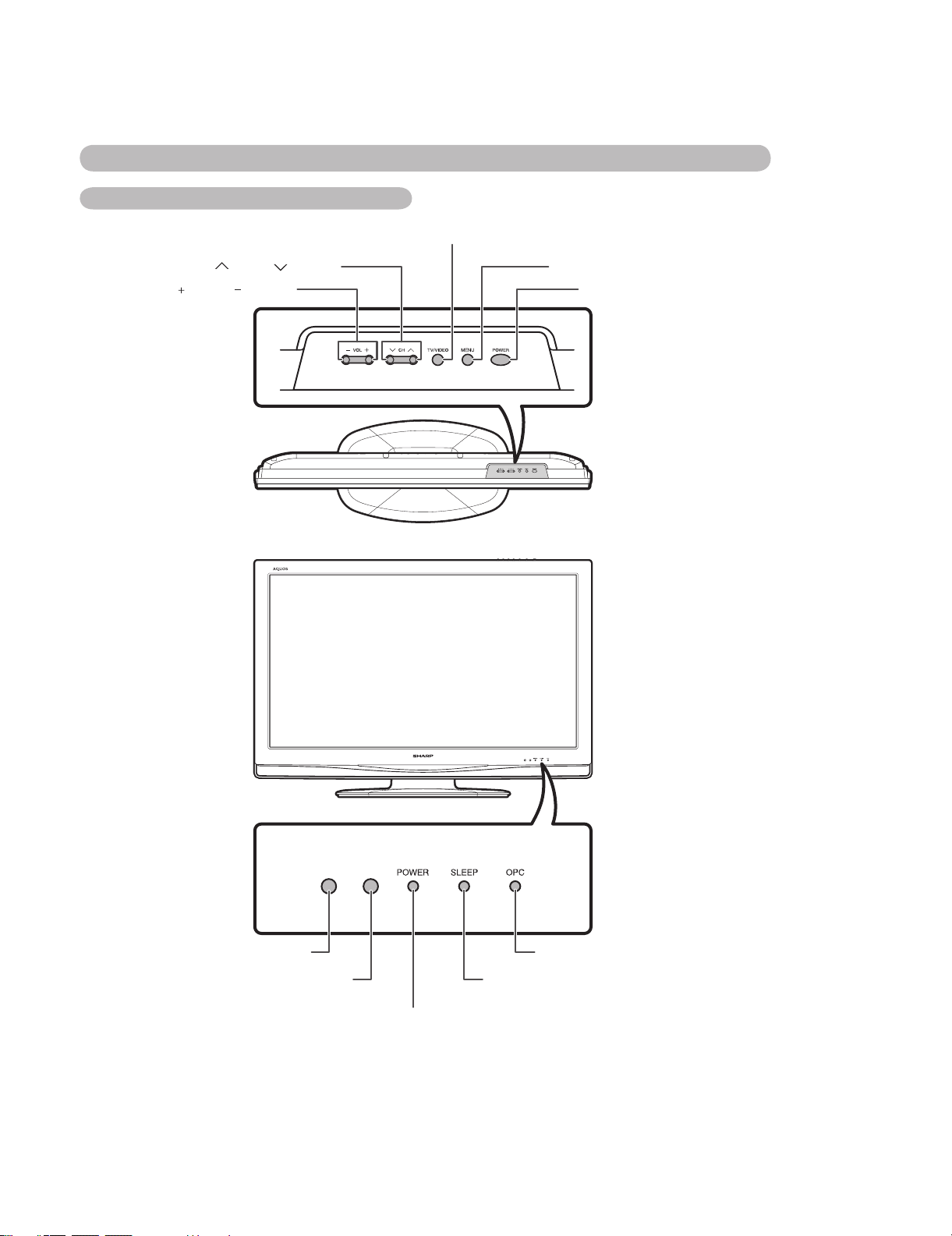
CHAPTER 2. OPERATION MANUAL
[1] OPERATION MANUAL
Part names
TV (Front)
TV/VIDEO button
LC-32A33M
Service Manual
Channel up ( )/down ( ) buttons
Volume up ( )/down ( ) buttons
MENU button
POWER (On/Off) button
Remote control sensor
OPC sensor
OPC indicator*
SLEEP timer indicator
POWER indicator
*OPC: Optical Picture Control
2 – 1
Page 16
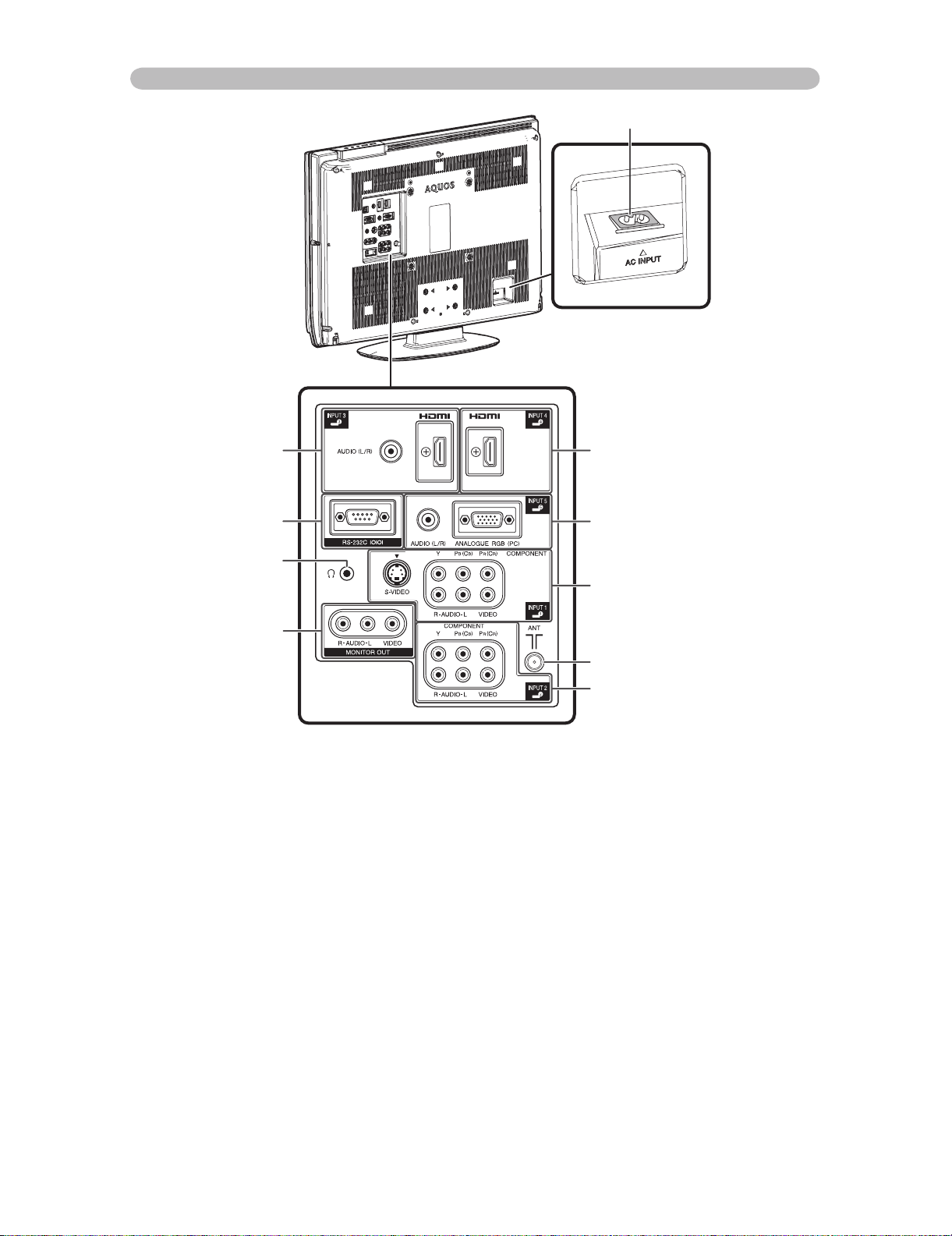
LC-32A33M
TV (Rear)
AC INPUT terminal
INPUT 3 (HDMI) terminals
RS-232C terminal
Headphone jack
MONITOR OUTPUT
terminal
INPUT 4 (HDMI) terminal
INPUT 5 (PC) terminals
INPUT 1 terminals
Antenna input terminal
INPUT 2 terminals
2 – 2
Page 17
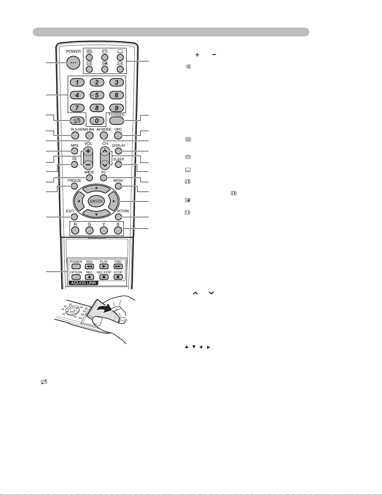
Remote control unit
1
2
3
4
5
6
7
8
9
10
11
12
1 POWER (STANDBY/ON)
To switch the power on and off.
20-9
Set the channel.
TELETEXT mode: Set the page.
3 (Flashback)
Press to return to the previous selected channel or
external input mode.
4 IN3(HDMI)
Directly select the INPUT 3 terminal.
5 IN4(HDMI)
Directly select the INPUT 4 terminal.
13
14
15
16
17
18
19
20
21
22
23
24
LC-32A33M
6 MPX
Select the sound multiplex mode.
7 VOL /VOL
Set the volume.
8 (Mute)
Mute the sound.
9WIDE
Change the wide image mode.
10 FREEZE
Freeze a motion picture on the screen.
11 EXIT
Return to the default screen.
12 AQUOS LINK buttons
If external equipment such as a AQUOS BD Player
is connected via HDMI cables and is AQUOS LINK
compatible, you can use these AQUOS LINK buttons.
13 (TELETEXT)
Select the TELETEXT mode. (all TV image, all TEXT
image, TV/TEXT image)
(Reveal hidden for TELETEXT)
TELETEXT mode: Display hidden characters.
(SUBTITLE for TELETEXT)
To turn the subtitles on and off.
(Hold)
TELETEXT mode: Stop updating Teletext pages
automatically. Press again to release the hold mode.
(Subpage)
Display the Teletext subpage directly.
(Top/Bottom/Full)
TELETEXT mode: Set the area of magnification.
14 TV/VIDEO (INPUT SOURCE)
Select an input source. (TV, INPUT 1, INPUT 2, INPUT 3,
INPUT4,INPUT5(PC))
15 OPC
To switch the Optical Picture Control on and off.
16 AV MODE
Select an audio and video setting: AV MODE (STANDARD,
MOVIE, GAME, USER, DYNAMIC (FIXED), DYNAMIC), PC
MODE (STANDARD, PC, USER).
17 DISPLAY
Display the channel or input information.
18 CH /CH
TV input mode: Select the channel.
TELETEXT mode: Select the page.
19 SLEEP
Set the Sleep timer.
20 PC
Directly select the INPUT 5 terminal.
21 MENU
Display the menu screen.
22 / / / (Cursor)
Select a desired item on the setting screen.
ENTER
Execute a command.
23 RETURN
MENU mode: Return to the previous menu screen.
24 Colour (Red/Green/Yellow/Blue)
TELETEXT mode: Select a page.
2 – 3
Page 18
LC-32A33M
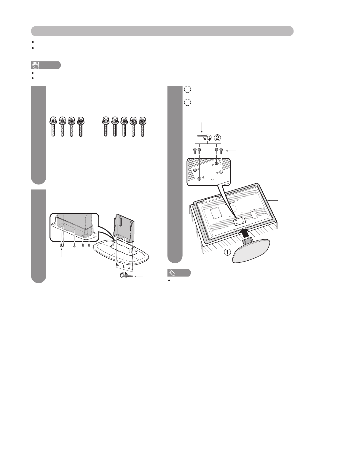
Attaching the stand
Before attaching (or detaching) the stand, unplug the AC cord from the AC INPUT terminal.
Before performing work spread cushioning over the base area to lay the TV on. This will prevent it from being
damaged.
CAUTION
Attach the stand in the correct direction.
Be sure to follow the instructions. Incorrect installation of the stand may result in the TV falling over.
Con“rm the screws supplied with the TV.
1
Screws (x4)
(usedinstep3)
Attach the supporting post for the stand unit
2
onto the base as shown below.
Screw
Screws (x5)
(usedinstep2)
3
bottom of the TV.
Insert and tighten the 4 screws into the 4
2
holes on the rear of the TV.
Hex key
Screw
Soft
cushion
Insert the stand into the openings on the
1
Hex
key
NOTE
To detach the stand, perform the steps in reverse order.
2 – 4
Page 19
PartsGuide
LC-32A33M
PARTS GUIDE
No. SY7B8LC32A33M
LCD COLOR TELEVISION
Note:
The reference numbers on the PWB
are arranged in alphabetical order.
[1] PRINTED WIRING BOARD
ASSEMBLIES
[2] LCD PANEL
[3] DUNTKE508FM02 (MAIN Unit)
[4] DUNTKE264FM03 (R/C, LED Unit)
MODEL
CONTENTS
LC-32A33M
[6] CABINET PARTS
[7] LCD PANEL UNIT
[8] SUPPLIED ACCESSORIES
[9] PACKING PARTS (NOT
REPLACEMENT ITEM)
[5] DUNTKE266FM03 (KEY Unit)
Parts marked with " " are important for maintaining the safety of the set. Be sure to replace these
parts with specified ones for maintaining the safety and performance of the set.
This document has been published to be used
for after sales service only.
The contents are subject to change without notice.
Page 20
LC-32A33M
NO. PARTS CODE
PRICE
RANK
NEW
MARK
PAR T
DELIVERY
[1] PRINTED WIRING BOARD ASSEMBLIES
DUNTKE264FM03 AP V R/C, LED Unit
DUNTKE266FM03 AG N V KEY Unit
DUNTKE508FM02 N V MAIN Unit
RUNTKA419WJQZ BU N V INVERTER /POWER Unit
[2] LCD PANEL
R1LK315T3GW20W DG N J LCD Panel Unit
[3] DUNTKE508FM02 (MAIN Unit)
C401 RC-KZA510WJPZY AB J CAPACITOR
C402 VCKYCZ1EB103KY AA J 0.01 25V Ceramic
C403 VCCCCZ1HH330JY AB J 33p 50V Ceramic
C404 VCCCCZ1HH330JY AB J 33p 50V Ceramic
C405 VCKYCZ1EF104ZY AA J 0.1 25V Ceramic
C408 RC-KZA510WJPZY AB J CAPACITOR
C409 VCKYCZ1EB103KY AA J 0.01 25V Ceramic
C410 VCKYCZ1EF104ZY AA J 0.1 25V Ceramic
C424 RC-KZA510WJPZY AB J CAPACITOR
C425 VCKYCZ1EB103KY AA J 0.01 25V Ceramic
C801 RC-KZA510WJPZY AB J CAPACITOR
C802 RC-KZA069WJZZY AB J CAPACITOR
C803 RC-KZA510WJPZY AB J CAPACITOR
C805 RC-KZA069WJZZY AB J CAPACITOR
C806 RC-KZA510WJPZY AB J CAPACITOR
C808 VCKYCY1AB105KY AB J 1 10V Ceramic
C809 RC-KZA069WJZZY AB J CAPACITOR
C810 VCKYCY1HB104KY AA J 0.1 50V Ceramic
C811 RC-KZA510WJPZY AB J CAPACITOR
C812 RC-KZA510WJPZY AB J CAPACITOR
C813 VCKYCY1HB104KY AA J 0.1 50V Ceramic
C815 VCKYCY1HB104KY AA J 0.1 50V Ceramic
C816 VCKYCY1HB104KY AA J 0.1 50V Ceramic
C817 VCKYCZ1EF104ZY AA J 0.1 25V Ceramic
C818 VCKYCY1HB104KY AA J 0.1 50V Ceramic
C819 VCKYCY1HB104KY AA J 0.1 50V Ceramic
C820 VCKYCZ1HB102KY AB J 1000p 50V Ceramic
C821 VCKYCY1HB104KY AA J 0.1 50V Ceramic
C822 VCKYCY1HB104KY AA J 0.1 50V Ceramic
C823 VCKYCY1HB104KY AA J 0.1 50V Ceramic
C824 VCKYCY1HB104KY AA J 0.1 50V Ceramic
C825 VCKYCZ1AB104KY AB J 0.1 10V Ceramic
C826 VCKYCZ1HB102KY AB J 1000p 50V Ceramic
C827 RC-KZA069WJZZY AB J
C828 VCKYCY1HB104KY AA J 0.1 50V Ceramic
C829 VCKYCY1HB104KY AA J 0.1 50V Ceramic
C830 VCKYCY1HB104KY AA J 0.1 50V Ceramic
C831 VCKYCY1HB104KY AA J 0.1 50V Ceramic
C832 RC-KZA069WJZZY AB J CAPACITOR
C833 VCKYCZ1EF104ZY AA J 0.1 25V Ceramic
C834 VCKYCZ1EF104ZY AA J 0.1 25V Ceramic
C835 VCKYCZ1EF104ZY AA J 0.1 25V Ceramic
C836 VCKYCZ1EF104ZY AA J 0.1 25V Ceramic
C837 VCKYCZ1EF104ZY AA J 0.1 25V Ceramic
C838 VCKYCZ1EF104ZY AA J 0.1 25V Ceramic
C839 VCKYCZ1EF104ZY AA J 0.1 25V Ceramic
C840 VCKYCZ1EF104ZY AA J 0.1 25V Ceramic
C841 VCKYCZ1EF104ZY AA J 0.1 25V Ceramic
C842 VCKYCZ1EF104ZY AA J 0.1 25V Ceramic
C843 VCKYCZ1EF104ZY AA J 0.1 25V Ceramic
C844 VCKYCZ1EF104ZY AA J 0.1 25V Ceramic
C845 VCKYCZ1EF104ZY AA J 0.1 25V Ceramic
C847 VCKYCZ1EF104ZY AA J 0.1 25V Ceramic
C848 VCKYCZ1EF104ZY AA J 0.1 25V Ceramic
C849 VCKYCZ1EF104ZY AA J 0.1 25V Ceramic
C850 VCKYCZ1HB102KY AB J 1000p 50V Ceramic
C851 RC-KZA510WJPZY AB J CAPACITOR
C853 VCKYCZ1EF104ZY AA J 0.1 25V Ceramic
C855 RC-KZA510WJPZY AB J CAPACITOR
C859 VCCCCZ1HH150JY AB J 15p 50V Ceramic
C860 VCKYCZ1EF104ZY AA J 0.1 25V Ceramic
C861 RC-KZA069WJZZY AB J CAPACITOR
C863 RC-KZA069WJZZY AB J CAPACITOR
C868 VCCCCZ1HH150JY AB J 15p 50V Ceramic
C872 VCKYCZ1EF104ZY AA J 0.1 25V Ceramic
C876 VCKYCZ1EF104ZY AA J 0.1 25V Ceramic
C879 RC-KZA510WJPZY AB J CAPACITOR
RC-KZA510WJPZY AB J CAPACITOR
C880
C881 VCKYCZ1EF104ZY AA J 0.1 25V Ceramic
C882 VCKYCZ1EF104ZY AA J 0.1 25V Ceramic
C883 VCKYCZ1EF104ZY AA J 0.1 25V Ceramic
C884 VCCCCY1HH9R0DY AA J 90p 50V Ceramic
C885 VCKYCY1HB103KY AA J 0.01 50V Ceramic
C886 VCKYCZ1EF104ZY AA J 0.1 25V Ceramic
C887 VCKYCZ1EF104ZY AA J 0.1 25V Ceramic
C888 VCCCCY1HH9R0DY AA J 90p 50V Ceramic
CAPACITOR
DESCRIPTION
2
Page 21

LC-32A33M
NO. PARTS CODE
PRICE
RANK
NEW
MARK
PAR T
DELIVERY
[3] DUNTKE508FM02 (MAIN Unit)
C889 VCKYCZ1EF104ZY AA J 0.1 25V Ceramic
C890 VCKYCZ1EF104ZY AA J 0.1 25V Ceramic
C891 RC-KZA510WJPZY AB J CAPACITOR
C892 VCKYCZ1EF104ZY AA J 0.1 25V Ceramic
C893 VCKYCZ1HB102KY AB J 1000p 50V Ceramic
C894 VCKYCZ1HB102KY AB J 1000p 50V Ceramic
C895 VCKYCZ1CB103KY AB J 0.01 16V Ceramic
C896 VCKYCZ1HB102KY AB J 1000p 50V Ceramic
C899 RC-KZA069WJZZY AB J CAPACITOR
C900 RC-KZA069WJZZY AB J CAPACITOR
C901 VCKYCZ1EF104ZY AA J 0.1 25V Ceramic
C902 VCKYCZ1EF104ZY AA J 0.1 25V Ceramic
C903 VCKYCZ1EF104ZY AA J 0.1 25V Ceramic
C904 RC-KZA069WJZZY AB J CAPACITOR
C906 VCEASX0JN476MY AC J 47 6.3V Electrolytic
C912 VCKYCY1AB105KY AB J 1 10V Ceramic
C913 VCCCCY1HH390JY AA J 39p 50V Ceramic
C920 RC-KZA510WJPZY AB J CAPACITOR
C1301 RC-KZA115WJZZY AB J CAPACITOR
C1302 RC-KZA115WJZZY AB J CAPACITOR
C1305 RC-KZA510WJPZY AB J CAPACITOR
C1306 VCKYCY1AB105KY AB J 1 10V Ceramic
C1307 VCKYCY1AB105KY AB J 1 10V Ceramic
C1308 VCKYCY1HB102KY AA J 1000p 50V Ceramic
C1309 VCKYCY1HB102KY AA J 1000p 50V Ceramic
C1310 VCKYCY1EF104ZY AA J 0.1 25V Ceramic
C1311 VCKYCY1AB105KY AB J 1 10V Ceramic
C1312 VCKYCY1AB105KY AB J 1 10V Ceramic
C1313 VCKYCY1AB105KY AB J 1 10V Ceramic
C1314 VCEASX1VN227MY AE J 220 35V Electrolytic
C1315 VCKYCY1EF104ZY AA J 0.1 25V Ceramic
C1316 RC-KZA114WJZZY AB J CAPACITOR
C1317 RC-KZA114WJZZY AB J CAPACITOR
C1318 VCKYCY1HB103KY AA J
C1319 VCKYCY1HB103KY AA J 0.01 50V Ceramic
C1320 VCKYCY1HB103KY AA J 0.01 50V Ceramic
C1321 VCKYCY1HB103KY AA J 0.01 50V Ceramic
C1322 RC-KZA619WJZZY AB V CAPACITOR
C1323 RC-KZA114WJZZY AB J CAPACITOR
C1324 RC-KZA114WJZZY AB J CAPACITOR
C1326 RC-KZA619WJZZY AB V CAPACITOR
C1328 VCKYCY1HB102KY AA J 1000p 50V Ceramic
C1501 VCKYCZ1AB104KY AB J 0.1 10V Ceramic
C1502 RC-KZA069WJZZY AB J CAPACITOR
C1503 RC-KZA069WJZZY AB J CAPACITOR
C1504 RC-KZA069WJZZY AB J CAPACITOR
C1505 RC-KZA069WJZZY AB J CAPACITOR
C1517 RC-KZA510WJPZY AB J CAPACITOR
C1531 VCKYCZ1EF104ZY AA J 0.1 25V Ceramic
C1532 VCKYCZ1HB102KY AB J 1000p 50V Ceramic
C1543 VCKYCZ1EF104ZY AA J 0.1 25V Ceramic
C1544 VCKYCZ1HB102KY AB J 1000p 50V Ceramic
C1545 VCKYCZ1EF104ZY AA J 0.1 25V Ceramic
C1546 VCKYCZ1HB102KY AB J 1000p 50V Ceramic
C1547 VCKYCZ1EF104ZY AA J 0.1 25V Ceramic
C1548 VCKYCZ1HB102KY AB J 1000p 50V Ceramic
C1551 RC-KZA510WJPZY AB J CAPACITOR
C1578 VCKYCZ1EF104ZY AA J 0.1 25V Ceramic
C1579 VCKYCZ1HB102KY AB J 1000p 50V Ceramic
C1582 VCKYCZ1EF104ZY AA J 0.1 25V Ceramic
C1583 VCKYCZ1HB102KY AB J 1000p 50V Ceramic
C1586 VCKYCZ1EF104ZY AA J 0.1 25V Ceramic
C1587 VCKYCZ1HB102KY AB J 1000p 50V Ceramic
C1589 VCKYCZ1EF104ZY AA J 0.1 25V Ceramic
C1591 VCKYCZ1HB102KY AB J 1000p 50V Ceramic
C1592 VCKYCZ1EF104ZY AA J 0.1 25V Ceramic
C1596 VCKYCZ1EF104ZY AA J 0.1 25V Ceramic
C1597
C1599 VCKYCZ1HB102KY AB J 1000p 50V Ceramic
C1608 RC-KZA510WJPZY AB J CAPACITOR
C1613 VCKYCZ1EF104ZY AA J 0.1 25V Ceramic
C1614 VCKYCZ1HB102KY AB J 1000p 50V Ceramic
C1615 VCKYCZ1EF104ZY AA J 0.1 25V Ceramic
C1616 VCKYCZ1HB102KY AB J 1000p 50V Ceramic
C1909 VCKYCY1EF104ZY AA J 0.1 25V Ceramic
C1910 RC-KZA510WJPZY AB J CAPACITOR
C1911 VCKYCY1EF104ZY AA J 0.1 25V Ceramic
C1912 VCKYCY1CB104KY AB J 0.1 16V Ceramic
C1913 VCKYCY1CB104KY AB J 0.1 16V Ceramic
C1914 VCKYCY1CB104KY AB J 0.1 16V Ceramic
C1915 VCKYCY1CB104KY AB J 0.1 16V Ceramic
C2001 VCKYCY1CB104KY AB J 0.1 16V Ceramic
C2014 VCKYCY1EF104ZY AA J 0.1 25V Ceramic
C2015 VCKYTV1CF684ZY AB J 0.68 16V Ceramic
C2018 RC-KZA510WJPZY AB J CAPACITOR
VCKYCZ1HB102KY AB J 1000p 50V Ceramic
0.01 50V Ceramic
DESCRIPTION
3
Page 22

LC-32A33M
NO. PARTS CODE
PRICE
RANK
NEW
MARK
PAR T
DELIVERY
[3] DUNTKE508FM02 (MAIN Unit)
C2019 VCKYCY1EF104ZY AA J 0.1 25V Ceramic
C2020 VCKYCY1HB222KY AA J 2200p 50V Ceramic
C2021 VCKYCY1EF104ZY AA J 0.1 25V Ceramic
C2022 VCKYCY1EF104ZY AA J 0.1 25V Ceramic
C2312 VCCCCY1HH100DY AA J 10p 50V Ceramic
C2313 VCCCCY1HH100DY AA J 10p 50V Ceramic
C2317 VCCCCY1HH102JY AB J 1000p 50V Ceramic
C2318 VCKYCY1HB221KY AA J 220p 50V Ceramic
C2801 VCKYCY1CB104KY AB J 0.1 16V Ceramic
C2804 RC-KZA510WJPZY AB J CAPACITOR
C2805 RC-KZA114WJZZY AB J CAPACITOR
C2806 VCCCCY1HH221JY AA J 220p 50V Ceramic
C2807 VCKYCY1HF103ZY AA J 0.01 50V Ceramic
C2808 VCCCCZ1HH221JY AB J 220p 50V Ceramic
C2809 VCKYCZ1EF104ZY AA J 0.1 25V Ceramic
C2810 RC-KZA110WJZZY AD J CAPACITOR
C2811 RC-KZA510WJPZY AB J CAPACITOR
C2812 RC-KZA510WJPZY AB J CAPACITOR
C2813 RC-KZA510WJPZY AB J CAPACITOR
C2814 RC-KZA069WJZZY AB J CAPACITOR
C2815 RC-KZA069WJZZY AB J CAPACITOR
C2827 VCKYCY1HF103ZY AA J 0.01 50V Ceramic
C2829 VCKYCY1HF103ZY AA J 0.01 50V Ceramic
C2830 VCCCCY1HH152JY AA V 1500p 50V Ceramic
C2831 VCCCCY1HH152JY AA V 1500p 50V Ceramic
C2832 VCKYCY1EF104ZY AA J 0.1 25V Ceramic
C2833 VCKYCY1EF104ZY AA J 0.1 25V Ceramic
C2836 VCKYCZ1HB332KY AA J 3300p 50V Ceramic
C2837 VCKYCZ1HB332KY AA J 3300p 50V Ceramic
C2838 RC-KZA510WJPZY AB J CAPACITOR
C2841 RC-KZA114WJZZY AB J CAPACITOR
C2843 RC-KZA114WJZZY AB J CAPACITOR
C2844 VCKYCY1EF104ZY AA J 0.1 25V Ceramic
C2846 VCKYCY1EF104ZY AA J
C2848 RC-KZA178WJZZY AC J CAPACITOR
C2849 RC-KZA510WJPZY AB J CAPACITOR
C2850 RC-KZA510WJPZY AB J CAPACITOR
C2852 RC-KZA510WJPZY AB J CAPACITOR
C2855 RC-KZA510WJPZY AB J CAPACITOR
C2856 RC-KZA178WJZZY AC J CAPACITOR
C3401 VCKYCY1HB103KY AA J 0.01 50V Ceramic
C3412 RC-KZA510WJPZY AB J CAPACITOR
C3413 RC-KZA510WJPZY AB J CAPACITOR
C3415 RC-KZA510WJPZY AB J CAPACITOR
C3417 RC-KZA510WJPZY AB J CAPACITOR
C3418 RC-KZA115WJZZY AB J CAPACITOR
C3419 RC-KZA115WJZZY AB J CAPACITOR
C3424 VCKYCY1EF104ZY AA J 0.1 25V Ceramic
C3425 VCKYCY1EF104ZY AA J 0.1 25V Ceramic
C3426 VCKYCY1EF104ZY AA J 0.1 25V Ceramic
C3427 VCKYCY1EF104ZY AA J 0.1 25V Ceramic
C3428 VCEASY1CN476MY AC J 47 16V Electrolytic
C3429 VCKYCY1CB104KY AB J 0.1 16V Ceramic
C3430 VCKYCY1AB474KY AC J 0.47 10V Ceramic
C3431 VCKYCY1AB474KY AC J 0.47 10V Ceramic
C3443 VCKYCY1AB105KY AB J 1 10V Ceramic
C3444 VCKYCY1AB474KY AC J 0.47 10V Ceramic
C3445 VCKYCY1AB474KY AC J 0.47 10V Ceramic
C3446 VCKYCY1AB474KY AC J 0.47 10V Ceramic
C3448 VCEASY1CN476MY AC J 47 16V Electrolytic
C3449 VCKYCY1AB474KY AC J 0.47 10V Ceramic
C3451 VCKYCZ1AB473KY AB J 0.047 10V Ceramic
C3452 VCKYCY1AB474KY AC J 0.47 10V Ceramic
C3453 VCEASX1CN106MY AC J 10 16V Electrolytic
C3455 RC-KZA510WJPZY AB J CAPACITOR
C3456 VCKYCY1AB105KY AB J 1 10V Ceramic
C3457 VCKYCY1AB474KY AC J 0.47 10V Ceramic
C3458
C3459 VCKYCY1AB474KY AC J 0.47 10V Ceramic
C3460 VCKYCY1AB474KY AC J 0.47 10V Ceramic
C3461 VCKYCY1AB474KY AC J 0.47 10V Ceramic
C3462 VCEASY1CN476MY AC J 47 16V Electrolytic
C3464 VCKYCY1CB104KY AB J 0.1 16V Ceramic
C3465 VCKYCY1AB474KY AC J 0.47 10V Ceramic
C3466 VCEASY1CN476MY AC J 47 16V Electrolytic
C3468 VCKYCY1CB104KY AB J 0.1 16V Ceramic
C3469 VCEASY1CN476MY AC J 47 16V Electrolytic
C3470 VCKYCY1CB104KY AB J 0.1 16V Ceramic
C3471 RC-KZA510WJPZY AB J CAPACITOR
C3472 RC-KZA510WJPZY AB J CAPACITOR
C3475 VCKYCY1HB102KY AA J 1000p 50V Ceramic
C3476 RC-KZA510WJPZY AB J CAPACITOR
C3477 VCCCCY1HH330JY AA J 33p 50V Ceramic
C3478 VCCCCY1HH100DY AA J 10p 50V Ceramic
C3479 VCCCCY1HH330JY AA J 33p 50V Ceramic
VCKYCY1AB474KY AC J 0.47 10V Ceramic
0.1 25V Ceramic
DESCRIPTION
4
Page 23

LC-32A33M
NO. PARTS CODE
PRICE
RANK
NEW
MARK
PAR T
DELIVERY
[3] DUNTKE508FM02 (MAIN Unit)
C3480 VCKYCY1EF104ZY AA J 0.1 25V Ceramic
C3482 VCKYCY1EF104ZY AA J 0.1 25V Ceramic
C3483 RC-KZA510WJPZY AB J CAPACITOR
C3484 RC-KZA510WJPZY AB J CAPACITOR
C3485 RC-KZA510WJPZY AB J CAPACITOR
C3487 RC-KZA510WJPZY AB J CAPACITOR
C3489 RC-KZA510WJPZY AB J CAPACITOR
C3491 RC-KZA510WJPZY AB J CAPACITOR
C3493 RC-KZA510WJPZY AB J CAPACITOR
C3495 RC-KZA510WJPZY AB J CAPACITOR
C3497 VCKYCY1AB105KY AB J 1 10V Ceramic
C3498 VCKYCY1AB105KY AB J 1 10V Ceramic
C3499 RC-KZA510WJPZY AB J CAPACITOR
C3500 VCKYCY1AB105KY AB J 1 10V Ceramic
C3501 VCKYTV1CB105KY AC J 1 16V Ceramic
C3502 VCKYTV1CB105KY AC J 1 16V Ceramic
C3503 VCEASX0JN227MY AC J 220 6.3V Electrolytic
C3504 VCEASX0JN227MY AC J 220 6.3V Electrolytic
C3505 VCEASX0JN227MY AC J 220 6.3V Electrolytic
C3601 RC-KZA510WJPZY AB J CAPACITOR
C3602 VCKYCY1EF104ZY AA J 0.1 25V Ceramic
C3604 VCKYCY1EF104ZY AA J 0.1 25V Ceramic
C3605 VCCCCY1HH101JY AA J 100p 50V Ceramic
C3606 VCCCCY1HH101JY AA J 100p 50V Ceramic
C3607 VCCCCY1HH120JY AA J 12p 50V Ceramic
C3608 VCCCCY1HH120JY AA J 12p 50V Ceramic
C3611 VCKYCY1CF104ZY AA J 0.1 16V Ceramic
C3612 VCKYCY1CF104ZY AA J 0.1 16V Ceramic
C3613 VCKYCY1CF104ZY AA J 0.1 16V Ceramic
C3615 VCKYTV1CB105KY AC J 1 16V Ceramic
C3616 RC-KZA115WJZZY AB J CAPACITOR
C3617 VCKYCY1CF104ZY AA J 0.1 16V Ceramic
C3618 RC-KZA510WJPZY AB J CAPACITOR
C3619 RC-KZA069WJZZY AB J
C3620 VCKYCY1CF104ZY AA J 0.1 16V Ceramic
C3622 VCKYCY1CF104ZY AA J 0.1 16V Ceramic
C3624 RC-KZA510WJPZY AB J CAPACITOR
C3626 VCKYTV1CB105KY AC J 1 16V Ceramic
C3627 VCKYTV1CB105KY AC J 1 16V Ceramic
C3628 VCKYCY1CF104ZY AA J 0.1 16V Ceramic
C3629 RC-KZA510WJPZY AB J CAPACITOR
C3630 VCKYCY1CF104ZY AA J 0.1 16V Ceramic
C3632 VCKYCY1CF104ZY AA J 0.1 16V Ceramic
C3634 RC-KZA069WJZZY AB J CAPACITOR
C3635 VCKYTV1CB105KY AC J 1 16V Ceramic
C3636 VCKYTV1CB105KY AC J 1 16V Ceramic
C3637 VCKYCY1CF104ZY AA J 0.1 16V Ceramic
C3639 VCKYTV1CB105KY AC J 1 16V Ceramic
C3640 VCKYTV1CB105KY AC J 1 16V Ceramic
C3643 VCKYCY1CF104ZY AA J 0.1 16V Ceramic
C3645 VCKYTV1CB105KY AC J 1 16V Ceramic
C3646 VCKYTV1CB105KY AC J 1 16V Ceramic
C3647 VCKYCY1CF104ZY AA J 0.1 16V Ceramic
C3649 RC-KZA069WJZZY AB J CAPACITOR
C3650 VCKYCY1CF104ZY AA J 0.1 16V Ceramic
C3652 VCKYCY1CF104ZY AA J 0.1 16V Ceramic
C3654 VCKYCY1HB102KY AA J 1000p 50V Ceramic
C3655 VCKYTV1CB105KY AC J 1 16V Ceramic
C3656 VCKYTV1CB105KY AC J 1 16V Ceramic
C3657 VCKYTV1CB105KY AC J 1 16V Ceramic
C3658 VCKYTV1CB105KY AC J 1 16V Ceramic
C3659 VCKYTV1CB105KY AC J 1 16V Ceramic
C3660 VCKYTV1CB105KY AC J 1 16V Ceramic
C3661 VCKYCY1CF104ZY AA J 0.1 16V Ceramic
C3662 VCKYTV1CB105KY AC J 1 16V Ceramic
C3663 VCKYCY1AB105KY AB J 1 10V Ceramic
C3665 RC-KZA510WJPZY AB J CAPACITOR
C3666
C3667 VCEASX1AN336MY AC J 33 10V Electrolytic
C3668 VCKYCY1AB105KY AB J 1 10V Ceramic
C3669 VCEASX0JN227MY AC J 220 6.3V Electrolytic
C3670 VCEASX0JN227MY AC J 220 6.3V Electrolytic
C3671 VCCCCY1HH101JY AA J 100p 50V Ceramic
C3672 VCCCCY1HH101JY AA J 100p 50V Ceramic
C3673 VCCCCY1HH101JY AA J 100p 50V Ceramic
C3674 VCCCCY1HH101JY AA J 100p 50V Ceramic
C3677 RC-KZA115WJZZY AB J CAPACITOR
C3679 RC-KZA510WJPZY AB J CAPACITOR
C3680 VCCCCY1HH101JY AA J 100p 50V Ceramic
C3681 VCCCCY1HH101JY AA J 100p 50V Ceramic
C3683 RC-KZA069WJZZY AB J CAPACITOR
C3684 RC-KZA069WJZZY AB J CAPACITOR
C3686 RC-KZA154WJZZY AB J CAPACITOR
C3687 VCKYCY1AB105KY AB J 1 10V Ceramic
C4201 VCCCCZ1HH150JY AB J 15p 50V Ceramic
VCKYCY1EF104ZY AA J 0.1 25V Ceramic
CAPACITOR
DESCRIPTION
5
Page 24

PartsGuide
LC-32A33M
PARTS GUIDE
No. SY7B8LC32A33M
LCD COLOR TELEVISION
Note:
The reference numbers on the PWB
are arranged in alphabetical order.
[1] PRINTED WIRING BOARD
ASSEMBLIES
[2] LCD PANEL
[3] DUNTKE508FM02 (MAIN Unit)
[4] DUNTKE264FM03 (R/C, LED Unit)
MODEL
CONTENTS
LC-32A33M
[6] CABINET PARTS
[7] LCD PANEL UNIT
[8] SUPPLIED ACCESSORIES
[9] PACKING PARTS (NOT
REPLACEMENT ITEM)
[5] DUNTKE266FM03 (KEY Unit)
Parts marked with " " are important for maintaining the safety of the set. Be sure to replace these
parts with specified ones for maintaining the safety and performance of the set.
This document has been published to be used
for after sales service only.
The contents are subject to change without notice.
Page 25

LC-32A33M
NO. PARTS CODE
PRICE
RANK
NEW
MARK
PAR T
DELIVERY
[1] PRINTED WIRING BOARD ASSEMBLIES
DUNTKE264FM03 AP V R/C, LED Unit
DUNTKE266FM03 AG N V KEY Unit
DUNTKE508FM02 N V MAIN Unit
RUNTKA419WJQZ BU N V INVERTER /POWER Unit
[2] LCD PANEL
R1LK315T3GW20W DG N J LCD Panel Unit
[3] DUNTKE508FM02 (MAIN Unit)
C401 RC-KZA510WJPZY AB J CAPACITOR
C402 VCKYCZ1EB103KY AA J 0.01 25V Ceramic
C403 VCCCCZ1HH330JY AB J 33p 50V Ceramic
C404 VCCCCZ1HH330JY AB J 33p 50V Ceramic
C405 VCKYCZ1EF104ZY AA J 0.1 25V Ceramic
C408 RC-KZA510WJPZY AB J CAPACITOR
C409 VCKYCZ1EB103KY AA J 0.01 25V Ceramic
C410 VCKYCZ1EF104ZY AA J 0.1 25V Ceramic
C424 RC-KZA510WJPZY AB J CAPACITOR
C425 VCKYCZ1EB103KY AA J 0.01 25V Ceramic
C801 RC-KZA510WJPZY AB J CAPACITOR
C802 RC-KZA069WJZZY AB J CAPACITOR
C803 RC-KZA510WJPZY AB J CAPACITOR
C805 RC-KZA069WJZZY AB J CAPACITOR
C806 RC-KZA510WJPZY AB J CAPACITOR
C808 VCKYCY1AB105KY AB J 1 10V Ceramic
C809 RC-KZA069WJZZY AB J CAPACITOR
C810 VCKYCY1HB104KY AA J 0.1 50V Ceramic
C811 RC-KZA510WJPZY AB J CAPACITOR
C812 RC-KZA510WJPZY AB J CAPACITOR
C813 VCKYCY1HB104KY AA J 0.1 50V Ceramic
C815 VCKYCY1HB104KY AA J 0.1 50V Ceramic
C816 VCKYCY1HB104KY AA J 0.1 50V Ceramic
C817 VCKYCZ1EF104ZY AA J 0.1 25V Ceramic
C818 VCKYCY1HB104KY AA J 0.1 50V Ceramic
C819 VCKYCY1HB104KY AA J 0.1 50V Ceramic
C820 VCKYCZ1HB102KY AB J 1000p 50V Ceramic
C821 VCKYCY1HB104KY AA J 0.1 50V Ceramic
C822 VCKYCY1HB104KY AA J 0.1 50V Ceramic
C823 VCKYCY1HB104KY AA J 0.1 50V Ceramic
C824 VCKYCY1HB104KY AA J 0.1 50V Ceramic
C825 VCKYCZ1AB104KY AB J 0.1 10V Ceramic
C826 VCKYCZ1HB102KY AB J 1000p 50V Ceramic
C827 RC-KZA069WJZZY AB J
C828 VCKYCY1HB104KY AA J 0.1 50V Ceramic
C829 VCKYCY1HB104KY AA J 0.1 50V Ceramic
C830 VCKYCY1HB104KY AA J 0.1 50V Ceramic
C831 VCKYCY1HB104KY AA J 0.1 50V Ceramic
C832 RC-KZA069WJZZY AB J CAPACITOR
C833 VCKYCZ1EF104ZY AA J 0.1 25V Ceramic
C834 VCKYCZ1EF104ZY AA J 0.1 25V Ceramic
C835 VCKYCZ1EF104ZY AA J 0.1 25V Ceramic
C836 VCKYCZ1EF104ZY AA J 0.1 25V Ceramic
C837 VCKYCZ1EF104ZY AA J 0.1 25V Ceramic
C838 VCKYCZ1EF104ZY AA J 0.1 25V Ceramic
C839 VCKYCZ1EF104ZY AA J 0.1 25V Ceramic
C840 VCKYCZ1EF104ZY AA J 0.1 25V Ceramic
C841 VCKYCZ1EF104ZY AA J 0.1 25V Ceramic
C842 VCKYCZ1EF104ZY AA J 0.1 25V Ceramic
C843 VCKYCZ1EF104ZY AA J 0.1 25V Ceramic
C844 VCKYCZ1EF104ZY AA J 0.1 25V Ceramic
C845 VCKYCZ1EF104ZY AA J 0.1 25V Ceramic
C847 VCKYCZ1EF104ZY AA J 0.1 25V Ceramic
C848 VCKYCZ1EF104ZY AA J 0.1 25V Ceramic
C849 VCKYCZ1EF104ZY AA J 0.1 25V Ceramic
C850 VCKYCZ1HB102KY AB J 1000p 50V Ceramic
C851 RC-KZA510WJPZY AB J CAPACITOR
C853 VCKYCZ1EF104ZY AA J 0.1 25V Ceramic
C855 RC-KZA510WJPZY AB J CAPACITOR
C859 VCCCCZ1HH150JY AB J 15p 50V Ceramic
C860 VCKYCZ1EF104ZY AA J 0.1 25V Ceramic
C861 RC-KZA069WJZZY AB J CAPACITOR
C863 RC-KZA069WJZZY AB J CAPACITOR
C868 VCCCCZ1HH150JY AB J 15p 50V Ceramic
C872 VCKYCZ1EF104ZY AA J 0.1 25V Ceramic
C876 VCKYCZ1EF104ZY AA J 0.1 25V Ceramic
C879 RC-KZA510WJPZY AB J CAPACITOR
RC-KZA510WJPZY AB J CAPACITOR
C880
C881 VCKYCZ1EF104ZY AA J 0.1 25V Ceramic
C882 VCKYCZ1EF104ZY AA J 0.1 25V Ceramic
C883 VCKYCZ1EF104ZY AA J 0.1 25V Ceramic
C884 VCCCCY1HH9R0DY AA J 90p 50V Ceramic
C885 VCKYCY1HB103KY AA J 0.01 50V Ceramic
C886 VCKYCZ1EF104ZY AA J 0.1 25V Ceramic
C887 VCKYCZ1EF104ZY AA J 0.1 25V Ceramic
C888 VCCCCY1HH9R0DY AA J 90p 50V Ceramic
CAPACITOR
DESCRIPTION
2
Page 26

LC-32A33M
NO. PARTS CODE
PRICE
RANK
NEW
MARK
PAR T
DELIVERY
[3] DUNTKE508FM02 (MAIN Unit)
C889 VCKYCZ1EF104ZY AA J 0.1 25V Ceramic
C890 VCKYCZ1EF104ZY AA J 0.1 25V Ceramic
C891 RC-KZA510WJPZY AB J CAPACITOR
C892 VCKYCZ1EF104ZY AA J 0.1 25V Ceramic
C893 VCKYCZ1HB102KY AB J 1000p 50V Ceramic
C894 VCKYCZ1HB102KY AB J 1000p 50V Ceramic
C895 VCKYCZ1CB103KY AB J 0.01 16V Ceramic
C896 VCKYCZ1HB102KY AB J 1000p 50V Ceramic
C899 RC-KZA069WJZZY AB J CAPACITOR
C900 RC-KZA069WJZZY AB J CAPACITOR
C901 VCKYCZ1EF104ZY AA J 0.1 25V Ceramic
C902 VCKYCZ1EF104ZY AA J 0.1 25V Ceramic
C903 VCKYCZ1EF104ZY AA J 0.1 25V Ceramic
C904 RC-KZA069WJZZY AB J CAPACITOR
C906 VCEASX0JN476MY AC J 47 6.3V Electrolytic
C912 VCKYCY1AB105KY AB J 1 10V Ceramic
C913 VCCCCY1HH390JY AA J 39p 50V Ceramic
C920 RC-KZA510WJPZY AB J CAPACITOR
C1301 RC-KZA115WJZZY AB J CAPACITOR
C1302 RC-KZA115WJZZY AB J CAPACITOR
C1305 RC-KZA510WJPZY AB J CAPACITOR
C1306 VCKYCY1AB105KY AB J 1 10V Ceramic
C1307 VCKYCY1AB105KY AB J 1 10V Ceramic
C1308 VCKYCY1HB102KY AA J 1000p 50V Ceramic
C1309 VCKYCY1HB102KY AA J 1000p 50V Ceramic
C1310 VCKYCY1EF104ZY AA J 0.1 25V Ceramic
C1311 VCKYCY1AB105KY AB J 1 10V Ceramic
C1312 VCKYCY1AB105KY AB J 1 10V Ceramic
C1313 VCKYCY1AB105KY AB J 1 10V Ceramic
C1314 VCEASX1VN227MY AE J 220 35V Electrolytic
C1315 VCKYCY1EF104ZY AA J 0.1 25V Ceramic
C1316 RC-KZA114WJZZY AB J CAPACITOR
C1317 RC-KZA114WJZZY AB J CAPACITOR
C1318 VCKYCY1HB103KY AA J
C1319 VCKYCY1HB103KY AA J 0.01 50V Ceramic
C1320 VCKYCY1HB103KY AA J 0.01 50V Ceramic
C1321 VCKYCY1HB103KY AA J 0.01 50V Ceramic
C1322 RC-KZA619WJZZY AB V CAPACITOR
C1323 RC-KZA114WJZZY AB J CAPACITOR
C1324 RC-KZA114WJZZY AB J CAPACITOR
C1326 RC-KZA619WJZZY AB V CAPACITOR
C1328 VCKYCY1HB102KY AA J 1000p 50V Ceramic
C1501 VCKYCZ1AB104KY AB J 0.1 10V Ceramic
C1502 RC-KZA069WJZZY AB J CAPACITOR
C1503 RC-KZA069WJZZY AB J CAPACITOR
C1504 RC-KZA069WJZZY AB J CAPACITOR
C1505 RC-KZA069WJZZY AB J CAPACITOR
C1517 RC-KZA510WJPZY AB J CAPACITOR
C1531 VCKYCZ1EF104ZY AA J 0.1 25V Ceramic
C1532 VCKYCZ1HB102KY AB J 1000p 50V Ceramic
C1543 VCKYCZ1EF104ZY AA J 0.1 25V Ceramic
C1544 VCKYCZ1HB102KY AB J 1000p 50V Ceramic
C1545 VCKYCZ1EF104ZY AA J 0.1 25V Ceramic
C1546 VCKYCZ1HB102KY AB J 1000p 50V Ceramic
C1547 VCKYCZ1EF104ZY AA J 0.1 25V Ceramic
C1548 VCKYCZ1HB102KY AB J 1000p 50V Ceramic
C1551 RC-KZA510WJPZY AB J CAPACITOR
C1578 VCKYCZ1EF104ZY AA J 0.1 25V Ceramic
C1579 VCKYCZ1HB102KY AB J 1000p 50V Ceramic
C1582 VCKYCZ1EF104ZY AA J 0.1 25V Ceramic
C1583 VCKYCZ1HB102KY AB J 1000p 50V Ceramic
C1586 VCKYCZ1EF104ZY AA J 0.1 25V Ceramic
C1587 VCKYCZ1HB102KY AB J 1000p 50V Ceramic
C1589 VCKYCZ1EF104ZY AA J 0.1 25V Ceramic
C1591 VCKYCZ1HB102KY AB J 1000p 50V Ceramic
C1592 VCKYCZ1EF104ZY AA J 0.1 25V Ceramic
C1596 VCKYCZ1EF104ZY AA J 0.1 25V Ceramic
C1597
C1599 VCKYCZ1HB102KY AB J 1000p 50V Ceramic
C1608 RC-KZA510WJPZY AB J CAPACITOR
C1613 VCKYCZ1EF104ZY AA J 0.1 25V Ceramic
C1614 VCKYCZ1HB102KY AB J 1000p 50V Ceramic
C1615 VCKYCZ1EF104ZY AA J 0.1 25V Ceramic
C1616 VCKYCZ1HB102KY AB J 1000p 50V Ceramic
C1909 VCKYCY1EF104ZY AA J 0.1 25V Ceramic
C1910 RC-KZA510WJPZY AB J CAPACITOR
C1911 VCKYCY1EF104ZY AA J 0.1 25V Ceramic
C1912 VCKYCY1CB104KY AB J 0.1 16V Ceramic
C1913 VCKYCY1CB104KY AB J 0.1 16V Ceramic
C1914 VCKYCY1CB104KY AB J 0.1 16V Ceramic
C1915 VCKYCY1CB104KY AB J 0.1 16V Ceramic
C2001 VCKYCY1CB104KY AB J 0.1 16V Ceramic
C2014 VCKYCY1EF104ZY AA J 0.1 25V Ceramic
C2015 VCKYTV1CF684ZY AB J 0.68 16V Ceramic
C2018 RC-KZA510WJPZY AB J CAPACITOR
VCKYCZ1HB102KY AB J 1000p 50V Ceramic
0.01 50V Ceramic
DESCRIPTION
3
Page 27

LC-32A33M
NO. PARTS CODE
PRICE
RANK
NEW
MARK
PAR T
DELIVERY
[3] DUNTKE508FM02 (MAIN Unit)
C2019 VCKYCY1EF104ZY AA J 0.1 25V Ceramic
C2020 VCKYCY1HB222KY AA J 2200p 50V Ceramic
C2021 VCKYCY1EF104ZY AA J 0.1 25V Ceramic
C2022 VCKYCY1EF104ZY AA J 0.1 25V Ceramic
C2312 VCCCCY1HH100DY AA J 10p 50V Ceramic
C2313 VCCCCY1HH100DY AA J 10p 50V Ceramic
C2317 VCCCCY1HH102JY AB J 1000p 50V Ceramic
C2318 VCKYCY1HB221KY AA J 220p 50V Ceramic
C2801 VCKYCY1CB104KY AB J 0.1 16V Ceramic
C2804 RC-KZA510WJPZY AB J CAPACITOR
C2805 RC-KZA114WJZZY AB J CAPACITOR
C2806 VCCCCY1HH221JY AA J 220p 50V Ceramic
C2807 VCKYCY1HF103ZY AA J 0.01 50V Ceramic
C2808 VCCCCZ1HH221JY AB J 220p 50V Ceramic
C2809 VCKYCZ1EF104ZY AA J 0.1 25V Ceramic
C2810 RC-KZA110WJZZY AD J CAPACITOR
C2811 RC-KZA510WJPZY AB J CAPACITOR
C2812 RC-KZA510WJPZY AB J CAPACITOR
C2813 RC-KZA510WJPZY AB J CAPACITOR
C2814 RC-KZA069WJZZY AB J CAPACITOR
C2815 RC-KZA069WJZZY AB J CAPACITOR
C2827 VCKYCY1HF103ZY AA J 0.01 50V Ceramic
C2829 VCKYCY1HF103ZY AA J 0.01 50V Ceramic
C2830 VCCCCY1HH152JY AA V 1500p 50V Ceramic
C2831 VCCCCY1HH152JY AA V 1500p 50V Ceramic
C2832 VCKYCY1EF104ZY AA J 0.1 25V Ceramic
C2833 VCKYCY1EF104ZY AA J 0.1 25V Ceramic
C2836 VCKYCZ1HB332KY AA J 3300p 50V Ceramic
C2837 VCKYCZ1HB332KY AA J 3300p 50V Ceramic
C2838 RC-KZA510WJPZY AB J CAPACITOR
C2841 RC-KZA114WJZZY AB J CAPACITOR
C2843 RC-KZA114WJZZY AB J CAPACITOR
C2844 VCKYCY1EF104ZY AA J 0.1 25V Ceramic
C2846 VCKYCY1EF104ZY AA J
C2848 RC-KZA178WJZZY AC J CAPACITOR
C2849 RC-KZA510WJPZY AB J CAPACITOR
C2850 RC-KZA510WJPZY AB J CAPACITOR
C2852 RC-KZA510WJPZY AB J CAPACITOR
C2855 RC-KZA510WJPZY AB J CAPACITOR
C2856 RC-KZA178WJZZY AC J CAPACITOR
C3401 VCKYCY1HB103KY AA J 0.01 50V Ceramic
C3412 RC-KZA510WJPZY AB J CAPACITOR
C3413 RC-KZA510WJPZY AB J CAPACITOR
C3415 RC-KZA510WJPZY AB J CAPACITOR
C3417 RC-KZA510WJPZY AB J CAPACITOR
C3418 RC-KZA115WJZZY AB J CAPACITOR
C3419 RC-KZA115WJZZY AB J CAPACITOR
C3424 VCKYCY1EF104ZY AA J 0.1 25V Ceramic
C3425 VCKYCY1EF104ZY AA J 0.1 25V Ceramic
C3426 VCKYCY1EF104ZY AA J 0.1 25V Ceramic
C3427 VCKYCY1EF104ZY AA J 0.1 25V Ceramic
C3428 VCEASY1CN476MY AC J 47 16V Electrolytic
C3429 VCKYCY1CB104KY AB J 0.1 16V Ceramic
C3430 VCKYCY1AB474KY AC J 0.47 10V Ceramic
C3431 VCKYCY1AB474KY AC J 0.47 10V Ceramic
C3443 VCKYCY1AB105KY AB J 1 10V Ceramic
C3444 VCKYCY1AB474KY AC J 0.47 10V Ceramic
C3445 VCKYCY1AB474KY AC J 0.47 10V Ceramic
C3446 VCKYCY1AB474KY AC J 0.47 10V Ceramic
C3448 VCEASY1CN476MY AC J 47 16V Electrolytic
C3449 VCKYCY1AB474KY AC J 0.47 10V Ceramic
C3451 VCKYCZ1AB473KY AB J 0.047 10V Ceramic
C3452 VCKYCY1AB474KY AC J 0.47 10V Ceramic
C3453 VCEASX1CN106MY AC J 10 16V Electrolytic
C3455 RC-KZA510WJPZY AB J CAPACITOR
C3456 VCKYCY1AB105KY AB J 1 10V Ceramic
C3457 VCKYCY1AB474KY AC J 0.47 10V Ceramic
C3458
C3459 VCKYCY1AB474KY AC J 0.47 10V Ceramic
C3460 VCKYCY1AB474KY AC J 0.47 10V Ceramic
C3461 VCKYCY1AB474KY AC J 0.47 10V Ceramic
C3462 VCEASY1CN476MY AC J 47 16V Electrolytic
C3464 VCKYCY1CB104KY AB J 0.1 16V Ceramic
C3465 VCKYCY1AB474KY AC J 0.47 10V Ceramic
C3466 VCEASY1CN476MY AC J 47 16V Electrolytic
C3468 VCKYCY1CB104KY AB J 0.1 16V Ceramic
C3469 VCEASY1CN476MY AC J 47 16V Electrolytic
C3470 VCKYCY1CB104KY AB J 0.1 16V Ceramic
C3471 RC-KZA510WJPZY AB J CAPACITOR
C3472 RC-KZA510WJPZY AB J CAPACITOR
C3475 VCKYCY1HB102KY AA J 1000p 50V Ceramic
C3476 RC-KZA510WJPZY AB J CAPACITOR
C3477 VCCCCY1HH330JY AA J 33p 50V Ceramic
C3478 VCCCCY1HH100DY AA J 10p 50V Ceramic
C3479 VCCCCY1HH330JY AA J 33p 50V Ceramic
VCKYCY1AB474KY AC J 0.47 10V Ceramic
0.1 25V Ceramic
DESCRIPTION
4
Page 28

LC-32A33M
NO. PARTS CODE
PRICE
RANK
NEW
MARK
PAR T
DELIVERY
[3] DUNTKE508FM02 (MAIN Unit)
C3480 VCKYCY1EF104ZY AA J 0.1 25V Ceramic
C3482 VCKYCY1EF104ZY AA J 0.1 25V Ceramic
C3483 RC-KZA510WJPZY AB J CAPACITOR
C3484 RC-KZA510WJPZY AB J CAPACITOR
C3485 RC-KZA510WJPZY AB J CAPACITOR
C3487 RC-KZA510WJPZY AB J CAPACITOR
C3489 RC-KZA510WJPZY AB J CAPACITOR
C3491 RC-KZA510WJPZY AB J CAPACITOR
C3493 RC-KZA510WJPZY AB J CAPACITOR
C3495 RC-KZA510WJPZY AB J CAPACITOR
C3497 VCKYCY1AB105KY AB J 1 10V Ceramic
C3498 VCKYCY1AB105KY AB J 1 10V Ceramic
C3499 RC-KZA510WJPZY AB J CAPACITOR
C3500 VCKYCY1AB105KY AB J 1 10V Ceramic
C3501 VCKYTV1CB105KY AC J 1 16V Ceramic
C3502 VCKYTV1CB105KY AC J 1 16V Ceramic
C3503 VCEASX0JN227MY AC J 220 6.3V Electrolytic
C3504 VCEASX0JN227MY AC J 220 6.3V Electrolytic
C3505 VCEASX0JN227MY AC J 220 6.3V Electrolytic
C3601 RC-KZA510WJPZY AB J CAPACITOR
C3602 VCKYCY1EF104ZY AA J 0.1 25V Ceramic
C3604 VCKYCY1EF104ZY AA J 0.1 25V Ceramic
C3605 VCCCCY1HH101JY AA J 100p 50V Ceramic
C3606 VCCCCY1HH101JY AA J 100p 50V Ceramic
C3607 VCCCCY1HH120JY AA J 12p 50V Ceramic
C3608 VCCCCY1HH120JY AA J 12p 50V Ceramic
C3611 VCKYCY1CF104ZY AA J 0.1 16V Ceramic
C3612 VCKYCY1CF104ZY AA J 0.1 16V Ceramic
C3613 VCKYCY1CF104ZY AA J 0.1 16V Ceramic
C3615 VCKYTV1CB105KY AC J 1 16V Ceramic
C3616 RC-KZA115WJZZY AB J CAPACITOR
C3617 VCKYCY1CF104ZY AA J 0.1 16V Ceramic
C3618 RC-KZA510WJPZY AB J CAPACITOR
C3619 RC-KZA069WJZZY AB J
C3620 VCKYCY1CF104ZY AA J 0.1 16V Ceramic
C3622 VCKYCY1CF104ZY AA J 0.1 16V Ceramic
C3624 RC-KZA510WJPZY AB J CAPACITOR
C3626 VCKYTV1CB105KY AC J 1 16V Ceramic
C3627 VCKYTV1CB105KY AC J 1 16V Ceramic
C3628 VCKYCY1CF104ZY AA J 0.1 16V Ceramic
C3629 RC-KZA510WJPZY AB J CAPACITOR
C3630 VCKYCY1CF104ZY AA J 0.1 16V Ceramic
C3632 VCKYCY1CF104ZY AA J 0.1 16V Ceramic
C3634 RC-KZA069WJZZY AB J CAPACITOR
C3635 VCKYTV1CB105KY AC J 1 16V Ceramic
C3636 VCKYTV1CB105KY AC J 1 16V Ceramic
C3637 VCKYCY1CF104ZY AA J 0.1 16V Ceramic
C3639 VCKYTV1CB105KY AC J 1 16V Ceramic
C3640 VCKYTV1CB105KY AC J 1 16V Ceramic
C3643 VCKYCY1CF104ZY AA J 0.1 16V Ceramic
C3645 VCKYTV1CB105KY AC J 1 16V Ceramic
C3646 VCKYTV1CB105KY AC J 1 16V Ceramic
C3647 VCKYCY1CF104ZY AA J 0.1 16V Ceramic
C3649 RC-KZA069WJZZY AB J CAPACITOR
C3650 VCKYCY1CF104ZY AA J 0.1 16V Ceramic
C3652 VCKYCY1CF104ZY AA J 0.1 16V Ceramic
C3654 VCKYCY1HB102KY AA J 1000p 50V Ceramic
C3655 VCKYTV1CB105KY AC J 1 16V Ceramic
C3656 VCKYTV1CB105KY AC J 1 16V Ceramic
C3657 VCKYTV1CB105KY AC J 1 16V Ceramic
C3658 VCKYTV1CB105KY AC J 1 16V Ceramic
C3659 VCKYTV1CB105KY AC J 1 16V Ceramic
C3660 VCKYTV1CB105KY AC J 1 16V Ceramic
C3661 VCKYCY1CF104ZY AA J 0.1 16V Ceramic
C3662 VCKYTV1CB105KY AC J 1 16V Ceramic
C3663 VCKYCY1AB105KY AB J 1 10V Ceramic
C3665 RC-KZA510WJPZY AB J CAPACITOR
C3666
C3667 VCEASX1AN336MY AC J 33 10V Electrolytic
C3668 VCKYCY1AB105KY AB J 1 10V Ceramic
C3669 VCEASX0JN227MY AC J 220 6.3V Electrolytic
C3670 VCEASX0JN227MY AC J 220 6.3V Electrolytic
C3671 VCCCCY1HH101JY AA J 100p 50V Ceramic
C3672 VCCCCY1HH101JY AA J 100p 50V Ceramic
C3673 VCCCCY1HH101JY AA J 100p 50V Ceramic
C3674 VCCCCY1HH101JY AA J 100p 50V Ceramic
C3677 RC-KZA115WJZZY AB J CAPACITOR
C3679 RC-KZA510WJPZY AB J CAPACITOR
C3680 VCCCCY1HH101JY AA J 100p 50V Ceramic
C3681 VCCCCY1HH101JY AA J 100p 50V Ceramic
C3683 RC-KZA069WJZZY AB J CAPACITOR
C3684 RC-KZA069WJZZY AB J CAPACITOR
C3686 RC-KZA154WJZZY AB J CAPACITOR
C3687 VCKYCY1AB105KY AB J 1 10V Ceramic
C4201 VCCCCZ1HH150JY AB J 15p 50V Ceramic
VCKYCY1EF104ZY AA J 0.1 25V Ceramic
CAPACITOR
DESCRIPTION
5
Page 29

LC-32A33M
NO. PARTS CODE
PRICE
RANK
NEW
MARK
PAR T
DELIVERY
[3] DUNTKE508FM02 (MAIN Unit)
C4202 VCCCCZ1HH150JY AB J 15p 50V Ceramic
C4203 RC-KZA069WJZZY AB J CAPACITOR
C4204 RC-KZA069WJZZY AB J CAPACITOR
C4205 RC-KZA069WJZZY AB J CAPACITOR
C4206 VCKYCZ1EF104ZY AA J 0.1 25V Ceramic
C4207 VCKYCZ1EF104ZY AA J 0.1 25V Ceramic
C4208 VCKYCZ1EF104ZY AA J 0.1 25V Ceramic
C4209 RC-KZA069WJZZY AB J CAPACITOR
C4210 VCKYCZ1EF104ZY AA J 0.1 25V Ceramic
C4211 VCKYCZ1EF104ZY AA J 0.1 25V Ceramic
C4212 VCKYCZ1EF104ZY AA J 0.1 25V Ceramic
C4213 VCKYCZ1EF104ZY AA J 0.1 25V Ceramic
C4214 VCKYCZ1EF104ZY AA J 0.1 25V Ceramic
C4215 VCKYCZ1EF104ZY AA J 0.1 25V Ceramic
C4216 VCKYCZ1EF104ZY AA J 0.1 25V Ceramic
C4217 VCKYCZ1EF104ZY AA J 0.1 25V Ceramic
C4218 VCKYCZ1EF104ZY AA J 0.1 25V Ceramic
C4219 VCKYCZ1EF104ZY AA J 0.1 25V Ceramic
C4220 VCKYCZ1EF104ZY AA J 0.1 25V Ceramic
C4221 VCKYCZ1EF104ZY AA J 0.1 25V Ceramic
C4222 VCKYCZ1EF104ZY AA J 0.1 25V Ceramic
C4223 VCKYCZ1EF104ZY AA J 0.1 25V Ceramic
C4224 VCKYCZ1EF104ZY AA J 0.1 25V Ceramic
C4225 VCKYCZ1EF104ZY AA J 0.1 25V Ceramic
C5228 VCCCCY1HH101JY AA J 100p 50V Ceramic
C5229 VCCCCY1HH101JY AA J 100p 50V Ceramic
C5230 VCCCCY1HH101JY AA J 100p 50V Ceramic
C8101 RC-KZA620WJZZY AA V CAPACITOR
C8102 RC-KZA620WJZZY AA V CAPACITOR
C8103 VCCCCZ1HH680JY AB J 68p 50V Ceramic
C8104 VCCCCZ1HH471JY AA J 470p 50V Ceramic
C8105 VCCCCZ1HH151JY AB J 150p 50V Ceramic
C8106 VCCCCZ1HH680JY AB J 68p 50V Ceramic
C8107 RC-KZA620WJZZY AA V
C8108 RC-KZA620WJZZY AA V CAPACITOR
C8109 VCCCCZ1HH821JY AA J 820p 50V Ceramic
C8110 RC-KZA620WJZZY AA V CAPACITOR
C8112 VCCCCZ1HH680JY AB J 68p 50V Ceramic
C8113 VCCCCZ1HH680JY AB J 68p 50V Ceramic
C8114 VCCCCZ1HH821JY AA J 820p 50V Ceramic
C8115 VCCCCZ1HH821JY AA J 820p 50V Ceramic
C8116 VCCCCZ1HH680JY AB J 68p 50V Ceramic
C8118 VCCCCZ1HH471JY AA J 470p 50V Ceramic
C8119 RC-KZA620WJZZY AA V CAPACITOR
C8121 VCCCCZ1HH680JY AB J 68p 50V Ceramic
C8122 RC-KZA620WJZZY AA V CAPACITOR
C8123 VCCCCZ1HH681JY AA J 680p 50V Ceramic
C8124 VCCCCZ1HH680JY AB J 68p 50V Ceramic
C8125 VCCCCZ1HH680JY AB J 68p 50V Ceramic
C8126 VCKYCZ1HB102KY AB J 1000p 50V Ceramic
C8127 VCKYCZ1HB102KY AB J 1000p 50V Ceramic
C8128 VCCCCZ1HH471JY AA J 470p 50V Ceramic
C8129 VCCCCZ1HH471JY AA J 470p 50V Ceramic
C8130 VCCCCZ1HH680JY AB J 68p 50V Ceramic
C8131 VCCCCZ1HH151JY AB J 150p 50V Ceramic
C8132 VCCCCZ1HH151JY AB J 150p 50V Ceramic
C8134 VCCCCZ1HH680JY AB J 68p 50V Ceramic
C8135 RC-KZA510WJPZY AB J CAPACITOR
C8139 RC-KZA510WJPZY AB J CAPACITOR
C8141 RC-KZA510WJPZY AB J CAPACITOR
C8142 RC-KZA510WJPZY AB J CAPACITOR
C8143 RC-KZA510WJPZY AB J CAPACITOR
C8201 RC-KZA114WJZZY AB J CAPACITOR
C8202 VCKYCY1HB104KY AA J 0.1 50V Ceramic
C8203 RC-KZA110WJZZY AD J CAPACITOR
C8204 RC-KZA620WJZZY AA V CAPACITOR
C8206 RC-KZA510WJPZY AB J CAPACITOR
C8207
C8208 RC-KZA114WJZZY AB J CAPACITOR
C8209 RC-KZA620WJZZY AA V CAPACITOR
C8211 RC-KZA620WJZZY AA V CAPACITOR
C8212 RC-KZA620WJZZY AA V CAPACITOR
C8213 RC-KZA620WJZZY AA V CAPACITOR
C8214 RC-KZA620WJZZY AA V CAPACITOR
C8216 RC-KZA620WJZZY AA V CAPACITOR
C8217 RC-KZA620WJZZY AA V CAPACITOR
C8218 VCKYCY1HB104KY AA J 0.1 50V Ceramic
C8219 RC-KZA620WJZZY AA V CAPACITOR
C8220 RC-KZA620WJZZY AA V CAPACITOR
C8221 RC-KZA620WJZZY AA V CAPACITOR
C8222 VCKYCZ1HB102KY AB J 1000p 50V Ceramic
C8223 RC-KZA114WJZZY AB J CAPACITOR
C8224 RC-KZA114WJZZY AB J CAPACITOR
C8225 RC-KZA114WJZZY AB J CAPACITOR
C8226 RC-KZA114WJZZY AB J CAPACITOR
RC-KZA620WJZZY AA V CAPACITOR
CAPACITOR
DESCRIPTION
6
Page 30

LC-32A33M
NO. PARTS CODE
PRICE
RANK
NEW
MARK
PAR T
DELIVERY
[3] DUNTKE508FM02 (MAIN Unit)
C8227 RC-KZA114WJZZY AB J CAPACITOR
C8228 VCKYCY1HB104KY AA J 0.1 50V Ceramic
C8229 VCKYCY1HB104KY AA J 0.1 50V Ceramic
C8330 RC-KZA110WJZZY AD J CAPACITOR
C8331 RC-KZA110WJZZY AD J CAPACITOR
C8401 VCKYCZ1EB682KY AB J 6800p 25V Ceramic
C8402 VCKYCY1EB104KY AB J 0.1 25V Ceramic
C8403 VCKYCZ1EB103KY AA J 0.01 25V Ceramic
C8406 RC-KZA510WJPZY AB J CAPACITOR
C8410 RC-KZA115WJZZY AB J CAPACITOR
C8411 VCCCCZ1HH330JY AB J 33p 50V Ceramic
C8412 VCCCCZ1HH680JY AB J 68p 50V Ceramic
C8413 RC-KZA114WJZZY AB J CAPACITOR
C8416 RC-KZA510WJPZY AB J CAPACITOR
C8417 VCCCCZ1HH330JY AB J 33p 50V Ceramic
C8419 VCKYCY1EB104KY AB J 0.1 25V Ceramic
C8420 VCKYCY1EB334KY AB J 0.33 25V Ceramic
C8422 VCAAPC1CJ226MY AG J 22 16V Electrolytic
C8423 VCCCCZ1HH330JY AB J 33p 50V Ceramic
C8424 VCKYCY1EB104KY AB J 0.1 25V Ceramic
C8425 VCKYCY1HB104KY AA J 0.1 50V Ceramic
C8426 RC-KZA110WJZZY AD J CAPACITOR
C8427 RC-KZA110WJZZY AD J CAPACITOR
C8428 RC-KZA110WJZZY AD J CAPACITOR
C8429 RC-KZA620WJZZY AA V CAPACITOR
C8430 RC-KZA114WJZZY AB J CAPACITOR
C8431 VCKYCZ1EB103KY AA J 0.01 25V Ceramic
C8432 RC-KZA619WJZZY AB V CAPACITOR
C8433 RC-KZA619WJZZY AB V CAPACITOR
C8434 RC-KZA110WJZZY AD J CAPACITOR
C8435 RC-KZA110WJZZY AD J CAPACITOR
C8436 RC-KZA114WJZZY AB J CAPACITOR
C8437 RC-KZA211WJZZY AB J CAPACITOR
C8438 VCKYCY1EB104KY AB J
C8439 RC-KZA510WJPZY AB J CAPACITOR
C8440 RC-KZA510WJPZY AB J CAPACITOR
C8441 RC-KZA510WJPZY AB J CAPACITOR
C8442 RC-KZA110WJZZY AD J CAPACITOR
C8444 RC-KZA110WJZZY AD J CAPACITOR
C8445 RC-KZA110WJZZY AD J CAPACITOR
C8447 VCKYCY1EB104KY AB J 0.1 25V Ceramic
C8448 VCCCCZ1HH680JY AB J 68p 50V Ceramic
C8449 VCCCCZ1HH680JY AB J 68p 50V Ceramic
C8450 VCCCCZ1HH101JY AB J 100p 50V Ceramic
C8451 VCCCCZ1HH101JY AB J 100p 50V Ceramic
C8452 VCAAPC1CJ226MY AG J 22 16V Electrolytic
C8453 VCAAPC1CJ226MY AG J 22 16V Electrolytic
C8454 VCCCCZ1HH101JY AB J 100p 50V Ceramic
C8455 RC-KZA213WJZZY AC J CAPACITOR
C8456 RC-KZA620WJZZY AA V CAPACITOR
C8457 VCKYCY1EB104KY AB J 0.1 25V Ceramic
C8458 RC-KZA211WJZZY AB J CAPACITOR
C8459 RC-KZA110WJZZY AD J CAPACITOR
C8460 RC-KZA211WJZZY AB J CAPACITOR
C8461 RC-KZA620WJZZY AA V CAPACITOR
C8462 RC-KZA110WJZZY AD J CAPACITOR
C8463 RC-KZA110WJZZY AD J CAPACITOR
C8464 RC-KZA110WJZZY AD J CAPACITOR
C8465 RC-KZA110WJZZY AD J CAPACITOR
C8466 VCCCCZ1HH330JY AB J 33p 50V Ceramic
C8467 VCKYCY1EB334KY AB J 0.33 25V Ceramic
C8468 VCKYCY1EB473KY AA J 0.047 25V Ceramic
C8469 VCKYCZ1HB331KY AA J 330p 50V Ceramic
C8470 VCKYCZ1HB331KY AA J 330p 50V Ceramic
C8471 RC-KZA110WJZZY AD J CAPACITOR
C8472 VCKYCZ1EB103KY AA J 0.01 25V Ceramic
C8473 RC-KZA620WJZZY AA V CAPACITOR
C8701
C8703 RC-KZA069WJZZY AB J CAPACITOR
C8704 RC-KZA510WJPZY AB J CAPACITOR
C8705 VCKYCZ1EF104ZY AA J 0.1 25V Ceramic
C8706 VCKYCZ1EF104ZY AA J 0.1 25V Ceramic
C8707 VCKYCZ1EF104ZY AA J 0.1 25V Ceramic
C8708 VCKYCZ1EF104ZY AA J 0.1 25V Ceramic
C8709 RC-KZA510WJPZY AB J CAPACITOR
C8710 RC-KZA069WJZZY AB J CAPACITOR
C8711 RC-KZA510WJPZY AB J CAPACITOR
C8712 VCKYCZ1EF104ZY AA J 0.1 25V Ceramic
C8713 VCKYCZ1EF104ZY AA J 0.1 25V Ceramic
C8714 VCKYCZ1EF104ZY AA J 0.1 25V Ceramic
C8715 VCKYCZ1EF104ZY AA J 0.1 25V Ceramic
C8716 VCKYCZ1EF104ZY AA J 0.1 25V Ceramic
C8717 VCKYCZ1EF104ZY AA J 0.1 25V Ceramic
C8718 VCKYCZ1EF104ZY AA J 0.1 25V Ceramic
C8719 VCKYCZ1EF104ZY AA J 0.1 25V Ceramic
RC-KZA510WJPZY AB J CAPACITOR
0.1 25V Ceramic
DESCRIPTION
7
Page 31

LC-32A33M
NO. PARTS CODE
PRICE
RANK
NEW
MARK
PAR T
DELIVERY
[3] DUNTKE508FM02 (MAIN Unit)
C8720 VCKYCZ1EF104ZY AA J 0.1 25V Ceramic
C8721 VCKYCZ1EF104ZY AA J 0.1 25V Ceramic
C8722 VCKYCZ1EF104ZY AA J 0.1 25V Ceramic
C8723 VCKYCZ1EF104ZY AA J 0.1 25V Ceramic
C8726 VCCCCZ1HH150JY AB J 15p 50V Ceramic
C8727 VCCCCZ1HH150JY AB J 15p 50V Ceramic
C8728 VCKYCZ1EF104ZY AA J 0.1 25V Ceramic
C8729 VCKYCZ1EF104ZY AA J 0.1 25V Ceramic
C8731 RC-KZA069WJZZY AB J CAPACITOR
C8732 RC-KZA069WJZZY AB J CAPACITOR
C8733 VCKYCY1AB105KY AB J 1 10V Ceramic
D404 VHDRB520S30-1Y AC J RB520S-30TE61
D405 VHDRB521S30-1Y AC J RB521S-30FJTE61
D406 VHDDAN222//-1Y AA J DAN222TL
D411 VHDRB521S30-1Y AC J RB521S-30FJTE61
D414 RH-EX0267TAZZY AB J TENTA
D415 RH-EX0267TAZZY AB J TENTA
D419 VHDRB521S30-1Y AC J RB521S-30FJTE61
D422 VHDRB521S30-1Y AC J RB521S-30FJTE61
D423 VHDRB521S30-1Y AC J RB521S-30FJTE61
D803 VHDMA111G++-1Y AA J MA2J1110GL
D805 VHDMA111G++-1Y AA J MA2J1110GL
D807 VHD1PS184++-1Y AB J 1PS184,115
D1301 VHD1PS184++-1Y AB J 1PS184,115
D1307 VHD1PS184++-1Y AB J 1PS184,115
D1502 VHDMA111G++-1Y AA J MA2J1110GL
D1908 VHD1PS184++-1Y AB J 1PS184,115
D2001 VHDMA111G++-1Y AA J MA2J1110GL
D2801 RH-EX0267TAZZY AB J TENTA
D2802 VHDRB056L40-1Y AC N V RB056L-40TE25
D2805 VHDRB056L40-1Y AC N V RB056L-40TE25
D2807 VHDRB056L40-1Y AC N V RB056L-40TE25
D3424 VHD1PS184++-1Y AB J 1PS184,115
D3601 VHD1PS184++-1Y AB J
D3604 VHDMA111G++-1Y AA J MA2J1110GL
D4202 VHDMA111G++-1Y AA J MA2J1110GL
D5204 RH-EX0267TAZZY AB J TENTA
D8101 VHDKDS184//-1Y AB J KDS184-RTK/P
D8401 VHDRB550EA+-1Y AC V RB550EATR
D8402 VHDRB550EA+-1Y AC V RB550EATR
D8403 VHDMA24D50+-1Y AD V MA24D5000B
D8405 VHDRB550EA+-1Y AC V RB550EATR
D8407 VHDRB160M30-1Y AC J RB160M-30TR
D8408 VHDMA3ZD12+-1Y AC V MA3ZD1200L
D8409 VHDRB160M30-1Y AC J RB160M-30TR
D8410 VHDD1F60///-1Y AC V
D8702 VHDMA111G++-1Y AA J MA2J1110GL
D8703 VHDMA111G++-1Y AA J MA2J1110GL
FB401 RBLN-0060TAZZY AB J BALUN
FB402 RBLN-0060TAZZY AB J BALUN
FB403 RBLN-0060TAZZY AB J BALUN
FB404 RBLN-0060TAZZY AB J BALUN
FB801 RBLN-0006TAZZY AB J BALUN
FB802 RBLN-0006TAZZY AB J BALUN
FB804 RBLN-0006TAZZY AB J BALUN
FB806 RBLN-0006TAZZY AB J BALUN
FB1301 RBLN-0064TAZZY AB J BALUN
FB1302 RBLN-0064TAZZY AB J BALUN
FB1303 RBLN-0064TAZZY AB J BALUN
FB1304 RBLN-0064TAZZY AB J BALUN
FB1509 RBLN-A274WJZZY AB J BALUN
FB1510 RBLN-A274WJZZY AB J BALUN
FB1901 RBLN-0254TAZZY AB J BALUN
FB1902 RBLN-0254TAZZY AB J BALUN
FB1903 RBLN-A328WJQZY AA J BALUN
FB2801 RBLN-A328WJQZY AA J BALUN
FB2802 RBLN-A331WJQZY AA J BALUN
FB2803 RBLN-A019WJZZY AA J
FB2804 RBLN-0253TAZZY AA J BALUN
FB2809 RBLN-0253TAZZY AA J BALUN
FB2810 RBLN-0253TAZZY AA J BALUN
FB2817 RBLN-A019WJZZY AA J BALUN
FB4201 RBLN-0050TAZZY AA J BALUN
FB4202 RBLN-0050TAZZY AA J BALUN
FB4203 RBLN-0050TAZZY AA J BALUN
FB4204 RBLN-0050TAZZY AA J BALUN
FB8101 RBLN-0253TAZZY AA J BALUN
FB8102 RBLN-0253TAZZY AA J BALUN
FB8103 RBLN-0253TAZZY AA J BALUN
FB8104 RBLN-0253TAZZY AA J BALUN
FB8105 RBLN-0253TAZZY AA J BALUN
FB8106 RBLN-0253TAZZY AA J BALUN
FB8701 RBLN-0050TAZZY AA J BALUN
FL801 RFILNA119WJZZY AC V FILTER
FL802 RFILNA119WJZZY AC V FILTER
1PS184,115
BALUN
DESCRIPTION
8
Page 32

LC-32A33M
NO. PARTS CODE
PRICE
RANK
NEW
MARK
PAR T
DELIVERY
[3] DUNTKE508FM02 (MAIN Unit)
FL803 RFILNA119WJZZY AC V FILTER
FL804 RFILNA119WJZZY AC V FILTER
FL805 RFILNA119WJZZY AC V FILTER
FL806 RFILNA119WJZZY AC V FILTER
FL807 RFILNA119WJZZY AC V FILTER
FL808 RFILNA119WJZZY AC V FILTER
FL809 RFILNA119WJZZY AC V FILTER
FL810 RFILNA119WJZZY AC V FILTER
FL811 RFILNA119WJZZY AC V FILTER
FL812 RFILNA119WJZZY AC V FILTER
FL2001 RFILZA003WJPZY AD J FILTER
FL8101 RFILZA007WJZZY AD J FILTER
IC401 RH-iXC460WJQZS V PC EDID
IC402 VHILVC2G14G-1Y AD J 74LVC2G14GW,125
IC404 RH-iXC458WJQZS V HDMI EDID
IC405 VHILVC2G14G-1Y AD J 74LVC2G14GW,125
IC406 RH-iXC459WJQZS V HDMI EDID
IC801 Not Available - - PWB Replacement Item.
IC802 VHIS170B33U-1Y AD N V
IC804 VHIS132B33M-1Y AD N V
IC805 VHIS132B33M-1Y AD N V
IC806 VHIS132B33M-1Y AD N V
IC807 VHIPQ1LAX95-1Y AD J PQ1LAX95MSPQ
IC808 VHIPQ015ENA-1Y AE J PQ015ENA1ZPH
IC1301 VHIYDA147SZ-1Y AM J YDA147-SZE2
IC1501 VHILCX125FT-1Y AD J TC74LCX125FT(EL,K)
IC1502 VHIS132B33M-1Y AD N V
IC1503 VHIPQ1LAX95-1Y AD J PQ1LAX95MSPQ
IC1507 VHISII9185+-1Q AP J SII9185CTU
IC1903 VHIISL83220-1Y AQ J ISL83220ECVZ-T(S2702)
IC1904 VHITC7SH00U-1Y AC J TC7SH00FU(T5L,JF,T
IC2001 RH-iXA654WJN1Q N V SYSCON
IC2002 VHITC7W66U/-1Y AE J TC7W66FU(TE12L,F)
IC2006 VHIPST8229N-1Y AC J IC-PST8229NR
IC2009 VHIBR24S64F-1Y AF N V
IC2801 VHIPQ200WNA-1Y AG J
IC2802 VHIMB39C011-1Y AK J MB39C011APFT-G-BND-ERE1
IC2803 VHIBD9305AF-1Y AK J BD9305AFVM-TR
IC2804 VHIS132B33M-1Y AD N V
IC2805 VHIPQ1L333M-1Y AD J PQ1L333M2SPQ
IC3409 VHIR2A11011-1Q AM V R2A11011FP
IC3601 VHINJM2746V-1Y AG J NJM2746V(TE1)
IC3602 VHITAS3208D-1Y AX J TAS3208PZPR
IC3603 VHI24LC256+-1Y AK N V 24LC256T-I/SN
IC3604 VHIBH3544F+-1Y AE J BH3544F-E2
IC3605 VHIS132B33M-1Y AD N V
IC3606 VHIPQ1LAX95-1Y AD J PQ1LAX95MSPQ
IC4201 VHIXV300+++-1Q AX V
IC4202 VHIS132B33M-1Y AD N V
IC4203 VHIPQ1LAX95-1Y AD J PQ1LAX95MSPQ
IC8101 VHI24LC256+-1Y AK N V 24LC256T-I/SN
IC8102 VHIT7WU04FK-1Y AD V
IC8103 VHIT3Z18AFG-1Q BA J T3Z18AFG-0003(O2)
IC8201 VHIBD8143MU-1Y AM V BD8143MUV-E2
IC8202 VHIBU55041+-1Y AF V BU55041HFN-TR-TR
IC8402 VHIBD8162EK-1Q AQ V BD8162EKV
IC8403 VHITB6815FG-1Y AN J TB6815FNG(O,EL)
IC8404 RH-IXB420WJZZY AH J LZ9FB274
IC8701 VHIPQ1LAX95-1Y AD J PQ1LAX95MSPQ
IC8702 Not Available - - PWB Replacement Item.
IC8703 VHIPQ1LAX95-1Y AD J PQ1LAX95MSPQ
J404 QJAKJ0008GEZZ AD J JACK
J405 QJAKJ0008GEZZ AD J JACK
J406 QJAKJA014WJZZ AD J JACK
J3401 QSOCDA035WJZZ AD J SOCKET
J3402 QJAKGA132WJQZ AF J JACK
J3403 QJAKLA037WJQZ AG J JACK
J3404 QJAKLA037WJQZ AG J JACK
L406 RCILFA228WJZZY AD J COIL
L407 RCILFA228WJZZY AD J COIL
L408 RCILFA228WJZZY AD J COIL
L409 RCILFA228WJZZY AD J COIL
L410 RCILFA228WJZZY AD J COIL
L411 RCILFA228WJZZY AD J COIL
L412 RCILFA228WJZZY AD J COIL
L413 RCILFA228WJZZY AD J COIL
L1303 RCILPA761WJQZY AD J COIL
L1304 RCILPA761WJQZY AD J COIL
L1305 RCILPA761WJQZY AD J COIL
L1306 RCILPA761WJQZY AD J COIL
L2801 RCILPA898WJZZY AC V COIL
L2802 RCILPA898WJZZY AC V COIL
L2803 RCILPA898WJZZY AC V COIL
L3404 VPCNN220J2R9NY AB J Peaking 22µH
L8101 RCILFA122WJZZY AD J COIL
PQ200WNA1ZPH
DESCRIPTION
9
Page 33

LC-32A33M
NO. PARTS CODE
PRICE
RANK
NEW
MARK
PAR T
DELIVERY
[3] DUNTKE508FM02 (MAIN Unit)
L8102 RCILFA122WJZZY AD J COIL
L8103 RCILFA122WJZZY AD J COIL
L8104 RCILFA122WJZZY AD J COIL
L8105 RCILFA122WJZZY AD J COIL
L8106 RCILFA122WJZZY AD J COIL
L8107 RCILFA122WJZZY AD J COIL
L8108 RCILFA122WJZZY AD J COIL
L8109 RCILFA122WJZZY AD J COIL
L8110 RCILFA122WJZZY AD J COIL
L8111 RCILFA122WJZZY AD J COIL
L8112 RCILFA122WJZZY AD J COIL
L8113 RCILFA275WJZZY AC V COIL
L8114 RCILFA275WJZZY AC V COIL
L8401 RCILPA085WJZZY AD J COIL
L8402 RCILPA084WJZZY AE J COIL
L8403 RCILPA084WJZZY AE J COIL
LUG3401 QLUGHA006WJZZY AC J LUG
LUG3402 QLUGHA006WJZZY AC J LUG
LUG3403 QLUGHA006WJZZY AC J LUG
LUG3404 QLUGHA006WJZZY AC J LUG
LUG3405 QLUGHA006WJZZY AC J LUG
LUG3406 QLUGHA006WJZZY AC J LUG
P1301 QPLGNA173WJZZY AD J PLUG
P2002 QPLGNA144WJZZY AF J PLUG
P2301 QPLGNA329WJZZY AD J PLUG
P2801 QPLGNA181WJZZY AF J PLUG
P5203 QPLGNA333WJZZY AD J PLUG
P5204 QPLGNA324WJZZY AC J PLUG
P8101 QPLGN0658REZZY AD J PLUG
Q404 VSRDTC144EE-1Y AA J PDTC144EE,115
Q405 VSRDTC144EE-1Y AA J PDTC144EE,115
Q407 VSRDTC144EE-1Y AA J PDTC144EE,115
Q408 VSRDTC144EE-1Y AA J PDTC144EE,115
Q410 VSRDTC144EE-1Y AA J
Q806 VS2SC3928AR-1Y AB J 2SC3928A-T112-1R
Q807 VS2SC3928AR-1Y AB J 2SC3928A-T112-1R
Q808 VS2SC3928AR-1Y AB J 2SC3928A-T112-1R
Q809 VSRDTC143ZE-1Y AB J PDTC143ZE,115
Q810 VSRDTA144EE-1Y AA J PDTA144EE,115
Q1301 VSKRC231S++-1Y AB J KRC231S-RTK/P
Q1302 VSKRC231S++-1Y AB J KRC231S-RTK/P
Q1304 VSRDTC144EE-1Y AA J PDTC144EE,115
Q1905 VSRDTC114EE-1Y AA J PDTC114EE,115
Q1906 VSRDTA114EE-1Y AB J PDTA114EE,115
Q1907 VSRDTC114EE-1Y AA J PDTC114EE,115
Q2019 VSRDTC114EE-1Y AA J PDTC114EE,115
Q2020 VS2SA1037KQ-1Y AA J 2SA1037KT146
Q2021 VSRDTC144EE-1Y AA J PDTC144EE,115
Q2025 VSRDTC143ZE-1Y AB J PDTC143ZE,115
Q2801 VSRSQ025P03-1Y AD N V
Q2802 VSRSQ025P03-1Y AD N V
Q2804 VSRSQ025P03-1Y AD N V
Q2821 VSRDTC144EE-1Y AA J PDTC144EE,115
Q2822 VSRSR025P03-1Y AD J RSR025P03TL
Q3401 VSKRC231S++-1Y AB J KRC231S-RTK/P
Q3402 VSKRC231S++-1Y AB J KRC231S-RTK/P
Q3403 VS2SC3928AR-1Y AB J 2SC3928A-T112-1R
Q3404 VS2SC3928AR-1Y AB J 2SC3928A-T112-1R
Q3405 VS2SC3928AR-1Y AB J 2SC3928A-T112-1R
Q3406 VS2SC3928AR-1Y AB J 2SC3928A-T112-1R
Q3407 VS2SC3928AR-1Y AB J 2SC3928A-T112-1R
Q3408 VS2SC3928AR-1Y AB J 2SC3928A-T112-1R
Q3409 VS2SC3928AR-1Y AB J 2SC3928A-T112-1R
Q3410 VS2SC3928AR-1Y AB J 2SC3928A-T112-1R
Q3411 VS2SC3928AR-1Y AB J 2SC3928A-T112-1R
Q3412 VSIMZ1A////-1Y AC J IMZ1AT108
Q3414 VS2SC3928AR-1Y AB J 2SC3928A-T112-1R
Q3415 VS2SC3928AR-1Y AB J 2SC3928A-T112-1R
Q3416
Q3417 VS2SA1530AR-1Y AB J 2SA1530A-T112-1R
Q3602 VSRDTC144EE-1Y AA J PDTC144EE,115
Q3606 VSRDTC144EE-1Y AA J PDTC144EE,115
Q8101 VSUM6K1NTN+-1Y AC J UM6K1NTN
Q8401 VSEMZ1+++++-1Y AC V EMZ1T2R
Q8402 VSDTC114EE/-1Y AB J DTC114EETL
Q8403 VSTPCP8602+-1Y AD V VSTPCP8602+-1Y
Q8405 VSTPCP8505+-1Y AD V VSTPCP8505+-1Y
Q8408 VS2SD1767++-1Y AD V 2SD1767T100
Q8410 VSRK7002A++-1Y AB V RK7002AT116
Q8412 VSTPCP8505+-1Y AD V VSTPCP8505+-1Y
Q8413 VSTPCP8602+-1Y AD V VSTPCP8602+-1Y
Q8414 VSTPCP8505+-1Y AD V VSTPCP8505+-1Y
Q8450 VSRSS050P03-1Y AG J RSS050P03TB
Q8704 VSRDTC144EE-1Y AA J PDTC144EE,115
Q8705 VSDTC114EE/-1Y AB J DTC114EETL
VS2SC3928AR-1Y AB J 2SC3928A-T112-1R
PDTC144EE,115
DESCRIPTION
10
Page 34

LC-32A33M
NO. PARTS CODE
PRICE
RANK
NEW
MARK
PAR T
DELIVERY
[3] DUNTKE508FM02 (MAIN Unit)
C4202 VCCCCZ1HH150JY AB J 15p 50V Ceramic
C4203 RC-KZA069WJZZY AB J CAPACITOR
C4204 RC-KZA069WJZZY AB J CAPACITOR
C4205 RC-KZA069WJZZY AB J CAPACITOR
C4206 VCKYCZ1EF104ZY AA J 0.1 25V Ceramic
C4207 VCKYCZ1EF104ZY AA J 0.1 25V Ceramic
C4208 VCKYCZ1EF104ZY AA J 0.1 25V Ceramic
C4209 RC-KZA069WJZZY AB J CAPACITOR
C4210 VCKYCZ1EF104ZY AA J 0.1 25V Ceramic
C4211 VCKYCZ1EF104ZY AA J 0.1 25V Ceramic
C4212 VCKYCZ1EF104ZY AA J 0.1 25V Ceramic
C4213 VCKYCZ1EF104ZY AA J 0.1 25V Ceramic
C4214 VCKYCZ1EF104ZY AA J 0.1 25V Ceramic
C4215 VCKYCZ1EF104ZY AA J 0.1 25V Ceramic
C4216 VCKYCZ1EF104ZY AA J 0.1 25V Ceramic
C4217 VCKYCZ1EF104ZY AA J 0.1 25V Ceramic
C4218 VCKYCZ1EF104ZY AA J 0.1 25V Ceramic
C4219 VCKYCZ1EF104ZY AA J 0.1 25V Ceramic
C4220 VCKYCZ1EF104ZY AA J 0.1 25V Ceramic
C4221 VCKYCZ1EF104ZY AA J 0.1 25V Ceramic
C4222 VCKYCZ1EF104ZY AA J 0.1 25V Ceramic
C4223 VCKYCZ1EF104ZY AA J 0.1 25V Ceramic
C4224 VCKYCZ1EF104ZY AA J 0.1 25V Ceramic
C4225 VCKYCZ1EF104ZY AA J 0.1 25V Ceramic
C5228 VCCCCY1HH101JY AA J 100p 50V Ceramic
C5229 VCCCCY1HH101JY AA J 100p 50V Ceramic
C5230 VCCCCY1HH101JY AA J 100p 50V Ceramic
C8101 RC-KZA620WJZZY AA V CAPACITOR
C8102 RC-KZA620WJZZY AA V CAPACITOR
C8103 VCCCCZ1HH680JY AB J 68p 50V Ceramic
C8104 VCCCCZ1HH471JY AA J 470p 50V Ceramic
C8105 VCCCCZ1HH151JY AB J 150p 50V Ceramic
C8106 VCCCCZ1HH680JY AB J 68p 50V Ceramic
C8107 RC-KZA620WJZZY AA V
C8108 RC-KZA620WJZZY AA V CAPACITOR
C8109 VCCCCZ1HH821JY AA J 820p 50V Ceramic
C8110 RC-KZA620WJZZY AA V CAPACITOR
C8112 VCCCCZ1HH680JY AB J 68p 50V Ceramic
C8113 VCCCCZ1HH680JY AB J 68p 50V Ceramic
C8114 VCCCCZ1HH821JY AA J 820p 50V Ceramic
C8115 VCCCCZ1HH821JY AA J 820p 50V Ceramic
C8116 VCCCCZ1HH680JY AB J 68p 50V Ceramic
C8118 VCCCCZ1HH471JY AA J 470p 50V Ceramic
C8119 RC-KZA620WJZZY AA V CAPACITOR
C8121 VCCCCZ1HH680JY AB J 68p 50V Ceramic
C8122 RC-KZA620WJZZY AA V CAPACITOR
C8123 VCCCCZ1HH681JY AA J 680p 50V Ceramic
C8124 VCCCCZ1HH680JY AB J 68p 50V Ceramic
C8125 VCCCCZ1HH680JY AB J 68p 50V Ceramic
C8126 VCKYCZ1HB102KY AB J 1000p 50V Ceramic
C8127 VCKYCZ1HB102KY AB J 1000p 50V Ceramic
C8128 VCCCCZ1HH471JY AA J 470p 50V Ceramic
C8129 VCCCCZ1HH471JY AA J 470p 50V Ceramic
C8130 VCCCCZ1HH680JY AB J 68p 50V Ceramic
C8131 VCCCCZ1HH151JY AB J 150p 50V Ceramic
C8132 VCCCCZ1HH151JY AB J 150p 50V Ceramic
C8134 VCCCCZ1HH680JY AB J 68p 50V Ceramic
C8135 RC-KZA510WJPZY AB J CAPACITOR
C8139 RC-KZA510WJPZY AB J CAPACITOR
C8141 RC-KZA510WJPZY AB J CAPACITOR
C8142 RC-KZA510WJPZY AB J CAPACITOR
C8143 RC-KZA510WJPZY AB J CAPACITOR
C8201 RC-KZA114WJZZY AB J CAPACITOR
C8202 VCKYCY1HB104KY AA J 0.1 50V Ceramic
C8203 RC-KZA110WJZZY AD J CAPACITOR
C8204 RC-KZA620WJZZY AA V CAPACITOR
C8206 RC-KZA510WJPZY AB J CAPACITOR
C8207
C8208 RC-KZA114WJZZY AB J CAPACITOR
C8209 RC-KZA620WJZZY AA V CAPACITOR
C8211 RC-KZA620WJZZY AA V CAPACITOR
C8212 RC-KZA620WJZZY AA V CAPACITOR
C8213 RC-KZA620WJZZY AA V CAPACITOR
C8214 RC-KZA620WJZZY AA V CAPACITOR
C8216 RC-KZA620WJZZY AA V CAPACITOR
C8217 RC-KZA620WJZZY AA V CAPACITOR
C8218 VCKYCY1HB104KY AA J 0.1 50V Ceramic
C8219 RC-KZA620WJZZY AA V CAPACITOR
C8220 RC-KZA620WJZZY AA V CAPACITOR
C8221 RC-KZA620WJZZY AA V CAPACITOR
C8222 VCKYCZ1HB102KY AB J 1000p 50V Ceramic
C8223 RC-KZA114WJZZY AB J CAPACITOR
C8224 RC-KZA114WJZZY AB J CAPACITOR
C8225 RC-KZA114WJZZY AB J CAPACITOR
C8226 RC-KZA114WJZZY AB J CAPACITOR
RC-KZA620WJZZY AA V CAPACITOR
CAPACITOR
DESCRIPTION
6
Page 35

LC-32A33M
NO. PARTS CODE
PRICE
RANK
NEW
MARK
PAR T
DELIVERY
[3] DUNTKE508FM02 (MAIN Unit)
C8227 RC-KZA114WJZZY AB J CAPACITOR
C8228 VCKYCY1HB104KY AA J 0.1 50V Ceramic
C8229 VCKYCY1HB104KY AA J 0.1 50V Ceramic
C8330 RC-KZA110WJZZY AD J CAPACITOR
C8331 RC-KZA110WJZZY AD J CAPACITOR
C8401 VCKYCZ1EB682KY AB J 6800p 25V Ceramic
C8402 VCKYCY1EB104KY AB J 0.1 25V Ceramic
C8403 VCKYCZ1EB103KY AA J 0.01 25V Ceramic
C8406 RC-KZA510WJPZY AB J CAPACITOR
C8410 RC-KZA115WJZZY AB J CAPACITOR
C8411 VCCCCZ1HH330JY AB J 33p 50V Ceramic
C8412 VCCCCZ1HH680JY AB J 68p 50V Ceramic
C8413 RC-KZA114WJZZY AB J CAPACITOR
C8416 RC-KZA510WJPZY AB J CAPACITOR
C8417 VCCCCZ1HH330JY AB J 33p 50V Ceramic
C8419 VCKYCY1EB104KY AB J 0.1 25V Ceramic
C8420 VCKYCY1EB334KY AB J 0.33 25V Ceramic
C8422 VCAAPC1CJ226MY AG J 22 16V Electrolytic
C8423 VCCCCZ1HH330JY AB J 33p 50V Ceramic
C8424 VCKYCY1EB104KY AB J 0.1 25V Ceramic
C8425 VCKYCY1HB104KY AA J 0.1 50V Ceramic
C8426 RC-KZA110WJZZY AD J CAPACITOR
C8427 RC-KZA110WJZZY AD J CAPACITOR
C8428 RC-KZA110WJZZY AD J CAPACITOR
C8429 RC-KZA620WJZZY AA V CAPACITOR
C8430 RC-KZA114WJZZY AB J CAPACITOR
C8431 VCKYCZ1EB103KY AA J 0.01 25V Ceramic
C8432 RC-KZA619WJZZY AB V CAPACITOR
C8433 RC-KZA619WJZZY AB V CAPACITOR
C8434 RC-KZA110WJZZY AD J CAPACITOR
C8435 RC-KZA110WJZZY AD J CAPACITOR
C8436 RC-KZA114WJZZY AB J CAPACITOR
C8437 RC-KZA211WJZZY AB J CAPACITOR
C8438 VCKYCY1EB104KY AB J
C8439 RC-KZA510WJPZY AB J CAPACITOR
C8440 RC-KZA510WJPZY AB J CAPACITOR
C8441 RC-KZA510WJPZY AB J CAPACITOR
C8442 RC-KZA110WJZZY AD J CAPACITOR
C8444 RC-KZA110WJZZY AD J CAPACITOR
C8445 RC-KZA110WJZZY AD J CAPACITOR
C8447 VCKYCY1EB104KY AB J 0.1 25V Ceramic
C8448 VCCCCZ1HH680JY AB J 68p 50V Ceramic
C8449 VCCCCZ1HH680JY AB J 68p 50V Ceramic
C8450 VCCCCZ1HH101JY AB J 100p 50V Ceramic
C8451 VCCCCZ1HH101JY AB J 100p 50V Ceramic
C8452 VCAAPC1CJ226MY AG J 22 16V Electrolytic
C8453 VCAAPC1CJ226MY AG J 22 16V Electrolytic
C8454 VCCCCZ1HH101JY AB J 100p 50V Ceramic
C8455 RC-KZA213WJZZY AC J CAPACITOR
C8456 RC-KZA620WJZZY AA V CAPACITOR
C8457 VCKYCY1EB104KY AB J 0.1 25V Ceramic
C8458 RC-KZA211WJZZY AB J CAPACITOR
C8459 RC-KZA110WJZZY AD J CAPACITOR
C8460 RC-KZA211WJZZY AB J CAPACITOR
C8461 RC-KZA620WJZZY AA V CAPACITOR
C8462 RC-KZA110WJZZY AD J CAPACITOR
C8463 RC-KZA110WJZZY AD J CAPACITOR
C8464 RC-KZA110WJZZY AD J CAPACITOR
C8465 RC-KZA110WJZZY AD J CAPACITOR
C8466 VCCCCZ1HH330JY AB J 33p 50V Ceramic
C8467 VCKYCY1EB334KY AB J 0.33 25V Ceramic
C8468 VCKYCY1EB473KY AA J 0.047 25V Ceramic
C8469 VCKYCZ1HB331KY AA J 330p 50V Ceramic
C8470 VCKYCZ1HB331KY AA J 330p 50V Ceramic
C8471 RC-KZA110WJZZY AD J CAPACITOR
C8472 VCKYCZ1EB103KY AA J 0.01 25V Ceramic
C8473 RC-KZA620WJZZY AA V CAPACITOR
C8701
C8703 RC-KZA069WJZZY AB J CAPACITOR
C8704 RC-KZA510WJPZY AB J CAPACITOR
C8705 VCKYCZ1EF104ZY AA J 0.1 25V Ceramic
C8706 VCKYCZ1EF104ZY AA J 0.1 25V Ceramic
C8707 VCKYCZ1EF104ZY AA J 0.1 25V Ceramic
C8708 VCKYCZ1EF104ZY AA J 0.1 25V Ceramic
C8709 RC-KZA510WJPZY AB J CAPACITOR
C8710 RC-KZA069WJZZY AB J CAPACITOR
C8711 RC-KZA510WJPZY AB J CAPACITOR
C8712 VCKYCZ1EF104ZY AA J 0.1 25V Ceramic
C8713 VCKYCZ1EF104ZY AA J 0.1 25V Ceramic
C8714 VCKYCZ1EF104ZY AA J 0.1 25V Ceramic
C8715 VCKYCZ1EF104ZY AA J 0.1 25V Ceramic
C8716 VCKYCZ1EF104ZY AA J 0.1 25V Ceramic
C8717 VCKYCZ1EF104ZY AA J 0.1 25V Ceramic
C8718 VCKYCZ1EF104ZY AA J 0.1 25V Ceramic
C8719 VCKYCZ1EF104ZY AA J 0.1 25V Ceramic
RC-KZA510WJPZY AB J CAPACITOR
0.1 25V Ceramic
DESCRIPTION
7
Page 36

LC-32A33M
NO. PARTS CODE
PRICE
RANK
NEW
MARK
PAR T
DELIVERY
[3] DUNTKE508FM02 (MAIN Unit)
C8720 VCKYCZ1EF104ZY AA J 0.1 25V Ceramic
C8721 VCKYCZ1EF104ZY AA J 0.1 25V Ceramic
C8722 VCKYCZ1EF104ZY AA J 0.1 25V Ceramic
C8723 VCKYCZ1EF104ZY AA J 0.1 25V Ceramic
C8726 VCCCCZ1HH150JY AB J 15p 50V Ceramic
C8727 VCCCCZ1HH150JY AB J 15p 50V Ceramic
C8728 VCKYCZ1EF104ZY AA J 0.1 25V Ceramic
C8729 VCKYCZ1EF104ZY AA J 0.1 25V Ceramic
C8731 RC-KZA069WJZZY AB J CAPACITOR
C8732 RC-KZA069WJZZY AB J CAPACITOR
C8733 VCKYCY1AB105KY AB J 1 10V Ceramic
D404 VHDRB520S30-1Y AC J RB520S-30TE61
D405 VHDRB521S30-1Y AC J RB521S-30FJTE61
D406 VHDDAN222//-1Y AA J DAN222TL
D411 VHDRB521S30-1Y AC J RB521S-30FJTE61
D414 RH-EX0267TAZZY AB J TENTA
D415 RH-EX0267TAZZY AB J TENTA
D419 VHDRB521S30-1Y AC J RB521S-30FJTE61
D422 VHDRB521S30-1Y AC J RB521S-30FJTE61
D423 VHDRB521S30-1Y AC J RB521S-30FJTE61
D803 VHDMA111G++-1Y AA J MA2J1110GL
D805 VHDMA111G++-1Y AA J MA2J1110GL
D807 VHD1PS184++-1Y AB J 1PS184,115
D1301 VHD1PS184++-1Y AB J 1PS184,115
D1307 VHD1PS184++-1Y AB J 1PS184,115
D1502 VHDMA111G++-1Y AA J MA2J1110GL
D1908 VHD1PS184++-1Y AB J 1PS184,115
D2001 VHDMA111G++-1Y AA J MA2J1110GL
D2801 RH-EX0267TAZZY AB J TENTA
D2802 VHDRB056L40-1Y AC N V RB056L-40TE25
D2805 VHDRB056L40-1Y AC N V RB056L-40TE25
D2807 VHDRB056L40-1Y AC N V RB056L-40TE25
D3424 VHD1PS184++-1Y AB J 1PS184,115
D3601 VHD1PS184++-1Y AB J
D3604 VHDMA111G++-1Y AA J MA2J1110GL
D4202 VHDMA111G++-1Y AA J MA2J1110GL
D5204 RH-EX0267TAZZY AB J TENTA
D8101 VHDKDS184//-1Y AB J KDS184-RTK/P
D8401 VHDRB550EA+-1Y AC V RB550EATR
D8402 VHDRB550EA+-1Y AC V RB550EATR
D8403 VHDMA24D50+-1Y AD V MA24D5000B
D8405 VHDRB550EA+-1Y AC V RB550EATR
D8407 VHDRB160M30-1Y AC J RB160M-30TR
D8408 VHDMA3ZD12+-1Y AC V MA3ZD1200L
D8409 VHDRB160M30-1Y AC J RB160M-30TR
D8410 VHDD1F60///-1Y AC V
D8702 VHDMA111G++-1Y AA J MA2J1110GL
D8703 VHDMA111G++-1Y AA J MA2J1110GL
FB401 RBLN-0060TAZZY AB J BALUN
FB402 RBLN-0060TAZZY AB J BALUN
FB403 RBLN-0060TAZZY AB J BALUN
FB404 RBLN-0060TAZZY AB J BALUN
FB801 RBLN-0006TAZZY AB J BALUN
FB802 RBLN-0006TAZZY AB J BALUN
FB804 RBLN-0006TAZZY AB J BALUN
FB806 RBLN-0006TAZZY AB J BALUN
FB1301 RBLN-0064TAZZY AB J BALUN
FB1302 RBLN-0064TAZZY AB J BALUN
FB1303 RBLN-0064TAZZY AB J BALUN
FB1304 RBLN-0064TAZZY AB J BALUN
FB1509 RBLN-A274WJZZY AB J BALUN
FB1510 RBLN-A274WJZZY AB J BALUN
FB1901 RBLN-0254TAZZY AB J BALUN
FB1902 RBLN-0254TAZZY AB J BALUN
FB1903 RBLN-A328WJQZY AA J BALUN
FB2801 RBLN-A328WJQZY AA J BALUN
FB2802 RBLN-A331WJQZY AA J BALUN
FB2803 RBLN-A019WJZZY AA J
FB2804 RBLN-0253TAZZY AA J BALUN
FB2809 RBLN-0253TAZZY AA J BALUN
FB2810 RBLN-0253TAZZY AA J BALUN
FB2817 RBLN-A019WJZZY AA J BALUN
FB4201 RBLN-0050TAZZY AA J BALUN
FB4202 RBLN-0050TAZZY AA J BALUN
FB4203 RBLN-0050TAZZY AA J BALUN
FB4204 RBLN-0050TAZZY AA J BALUN
FB8101 RBLN-0253TAZZY AA J BALUN
FB8102 RBLN-0253TAZZY AA J BALUN
FB8103 RBLN-0253TAZZY AA J BALUN
FB8104 RBLN-0253TAZZY AA J BALUN
FB8105 RBLN-0253TAZZY AA J BALUN
FB8106 RBLN-0253TAZZY AA J BALUN
FB8701 RBLN-0050TAZZY AA J BALUN
FL801 RFILNA119WJZZY AC V FILTER
FL802 RFILNA119WJZZY AC V FILTER
1PS184,115
BALUN
DESCRIPTION
8
Page 37

LC-32A33M
NO. PARTS CODE
PRICE
RANK
NEW
MARK
PAR T
DELIVERY
[3] DUNTKE508FM02 (MAIN Unit)
FL803 RFILNA119WJZZY AC V FILTER
FL804 RFILNA119WJZZY AC V FILTER
FL805 RFILNA119WJZZY AC V FILTER
FL806 RFILNA119WJZZY AC V FILTER
FL807 RFILNA119WJZZY AC V FILTER
FL808 RFILNA119WJZZY AC V FILTER
FL809 RFILNA119WJZZY AC V FILTER
FL810 RFILNA119WJZZY AC V FILTER
FL811 RFILNA119WJZZY AC V FILTER
FL812 RFILNA119WJZZY AC V FILTER
FL2001 RFILZA003WJPZY AD J FILTER
FL8101 RFILZA007WJZZY AD J FILTER
IC401 RH-iXC460WJQZS V PC EDID
IC402 VHILVC2G14G-1Y AD J 74LVC2G14GW,125
IC404 RH-iXC458WJQZS V HDMI EDID
IC405 VHILVC2G14G-1Y AD J 74LVC2G14GW,125
IC406 RH-iXC459WJQZS V HDMI EDID
IC801 Not Available - - PWB Replacement Item.
IC802 VHIS170B33U-1Y AD N V
IC804 VHIS132B33M-1Y AD N V
IC805 VHIS132B33M-1Y AD N V
IC806 VHIS132B33M-1Y AD N V
IC807 VHIPQ1LAX95-1Y AD J PQ1LAX95MSPQ
IC808 VHIPQ015ENA-1Y AE J PQ015ENA1ZPH
IC1301 VHIYDA147SZ-1Y AM J YDA147-SZE2
IC1501 VHILCX125FT-1Y AD J TC74LCX125FT(EL,K)
IC1502 VHIS132B33M-1Y AD N V
IC1503 VHIPQ1LAX95-1Y AD J PQ1LAX95MSPQ
IC1507 VHISII9185+-1Q AP J SII9185CTU
IC1903 VHIISL83220-1Y AQ J ISL83220ECVZ-T(S2702)
IC1904 VHITC7SH00U-1Y AC J TC7SH00FU(T5L,JF,T
IC2001 RH-iXA654WJN1Q N V SYSCON
IC2002 VHITC7W66U/-1Y AE J TC7W66FU(TE12L,F)
IC2006 VHIPST8229N-1Y AC J IC-PST8229NR
IC2009 VHIBR24S64F-1Y AF N V
IC2801 VHIPQ200WNA-1Y AG J
IC2802 VHIMB39C011-1Y AK J MB39C011APFT-G-BND-ERE1
IC2803 VHIBD9305AF-1Y AK J BD9305AFVM-TR
IC2804 VHIS132B33M-1Y AD N V
IC2805 VHIPQ1L333M-1Y AD J PQ1L333M2SPQ
IC3409 VHIR2A11011-1Q AM V R2A11011FP
IC3601 VHINJM2746V-1Y AG J NJM2746V(TE1)
IC3602 VHITAS3208D-1Y AX J TAS3208PZPR
IC3603 VHI24LC256+-1Y AK N V 24LC256T-I/SN
IC3604 VHIBH3544F+-1Y AE J BH3544F-E2
IC3605 VHIS132B33M-1Y AD N V
IC3606 VHIPQ1LAX95-1Y AD J PQ1LAX95MSPQ
IC4201 VHIXV300+++-1Q AX V
IC4202 VHIS132B33M-1Y AD N V
IC4203 VHIPQ1LAX95-1Y AD J PQ1LAX95MSPQ
IC8101 VHI24LC256+-1Y AK N V 24LC256T-I/SN
IC8102 VHIT7WU04FK-1Y AD V
IC8103 VHIT3Z18AFG-1Q BA J T3Z18AFG-0003(O2)
IC8201 VHIBD8143MU-1Y AM V BD8143MUV-E2
IC8202 VHIBU55041+-1Y AF V BU55041HFN-TR-TR
IC8402 VHIBD8162EK-1Q AQ V BD8162EKV
IC8403 VHITB6815FG-1Y AN J TB6815FNG(O,EL)
IC8404 RH-IXB420WJZZY AH J LZ9FB274
IC8701 VHIPQ1LAX95-1Y AD J PQ1LAX95MSPQ
IC8702 Not Available - - PWB Replacement Item.
IC8703 VHIPQ1LAX95-1Y AD J PQ1LAX95MSPQ
J404 QJAKJ0008GEZZ AD J JACK
J405 QJAKJ0008GEZZ AD J JACK
J406 QJAKJA014WJZZ AD J JACK
J3401 QSOCDA035WJZZ AD J SOCKET
J3402 QJAKGA132WJQZ AF J JACK
J3403 QJAKLA037WJQZ AG J JACK
J3404 QJAKLA037WJQZ AG J JACK
L406 RCILFA228WJZZY AD J COIL
L407 RCILFA228WJZZY AD J COIL
L408 RCILFA228WJZZY AD J COIL
L409 RCILFA228WJZZY AD J COIL
L410 RCILFA228WJZZY AD J COIL
L411 RCILFA228WJZZY AD J COIL
L412 RCILFA228WJZZY AD J COIL
L413 RCILFA228WJZZY AD J COIL
L1303 RCILPA761WJQZY AD J COIL
L1304 RCILPA761WJQZY AD J COIL
L1305 RCILPA761WJQZY AD J COIL
L1306 RCILPA761WJQZY AD J COIL
L2801 RCILPA898WJZZY AC V COIL
L2802 RCILPA898WJZZY AC V COIL
L2803 RCILPA898WJZZY AC V COIL
L3404 VPCNN220J2R9NY AB J Peaking 22µH
L8101 RCILFA122WJZZY AD J COIL
PQ200WNA1ZPH
DESCRIPTION
9
Page 38

LC-32A33M
NO. PARTS CODE
PRICE
RANK
NEW
MARK
PAR T
DELIVERY
[3] DUNTKE508FM02 (MAIN Unit)
L8102 RCILFA122WJZZY AD J COIL
L8103 RCILFA122WJZZY AD J COIL
L8104 RCILFA122WJZZY AD J COIL
L8105 RCILFA122WJZZY AD J COIL
L8106 RCILFA122WJZZY AD J COIL
L8107 RCILFA122WJZZY AD J COIL
L8108 RCILFA122WJZZY AD J COIL
L8109 RCILFA122WJZZY AD J COIL
L8110 RCILFA122WJZZY AD J COIL
L8111 RCILFA122WJZZY AD J COIL
L8112 RCILFA122WJZZY AD J COIL
L8113 RCILFA275WJZZY AC V COIL
L8114 RCILFA275WJZZY AC V COIL
L8401 RCILPA085WJZZY AD J COIL
L8402 RCILPA084WJZZY AE J COIL
L8403 RCILPA084WJZZY AE J COIL
LUG3401 QLUGHA006WJZZY AC J LUG
LUG3402 QLUGHA006WJZZY AC J LUG
LUG3403 QLUGHA006WJZZY AC J LUG
LUG3404 QLUGHA006WJZZY AC J LUG
LUG3405 QLUGHA006WJZZY AC J LUG
LUG3406 QLUGHA006WJZZY AC J LUG
P1301 QPLGNA173WJZZY AD J PLUG
P2002 QPLGNA144WJZZY AF J PLUG
P2301 QPLGNA329WJZZY AD J PLUG
P2801 QPLGNA181WJZZY AF J PLUG
P5203 QPLGNA333WJZZY AD J PLUG
P5204 QPLGNA324WJZZY AC J PLUG
P8101 QPLGN0658REZZY AD J PLUG
Q404 VSRDTC144EE-1Y AA J PDTC144EE,115
Q405 VSRDTC144EE-1Y AA J PDTC144EE,115
Q407 VSRDTC144EE-1Y AA J PDTC144EE,115
Q408 VSRDTC144EE-1Y AA J PDTC144EE,115
Q410 VSRDTC144EE-1Y AA J
Q806 VS2SC3928AR-1Y AB J 2SC3928A-T112-1R
Q807 VS2SC3928AR-1Y AB J 2SC3928A-T112-1R
Q808 VS2SC3928AR-1Y AB J 2SC3928A-T112-1R
Q809 VSRDTC143ZE-1Y AB J PDTC143ZE,115
Q810 VSRDTA144EE-1Y AA J PDTA144EE,115
Q1301 VSKRC231S++-1Y AB J KRC231S-RTK/P
Q1302 VSKRC231S++-1Y AB J KRC231S-RTK/P
Q1304 VSRDTC144EE-1Y AA J PDTC144EE,115
Q1905 VSRDTC114EE-1Y AA J PDTC114EE,115
Q1906 VSRDTA114EE-1Y AB J PDTA114EE,115
Q1907 VSRDTC114EE-1Y AA J PDTC114EE,115
Q2019 VSRDTC114EE-1Y AA J PDTC114EE,115
Q2020 VS2SA1037KQ-1Y AA J 2SA1037KT146
Q2021 VSRDTC144EE-1Y AA J PDTC144EE,115
Q2025 VSRDTC143ZE-1Y AB J PDTC143ZE,115
Q2801 VSRSQ025P03-1Y AD N V
Q2802 VSRSQ025P03-1Y AD N V
Q2804 VSRSQ025P03-1Y AD N V
Q2821 VSRDTC144EE-1Y AA J PDTC144EE,115
Q2822 VSRSR025P03-1Y AD J RSR025P03TL
Q3401 VSKRC231S++-1Y AB J KRC231S-RTK/P
Q3402 VSKRC231S++-1Y AB J KRC231S-RTK/P
Q3403 VS2SC3928AR-1Y AB J 2SC3928A-T112-1R
Q3404 VS2SC3928AR-1Y AB J 2SC3928A-T112-1R
Q3405 VS2SC3928AR-1Y AB J 2SC3928A-T112-1R
Q3406 VS2SC3928AR-1Y AB J 2SC3928A-T112-1R
Q3407 VS2SC3928AR-1Y AB J 2SC3928A-T112-1R
Q3408 VS2SC3928AR-1Y AB J 2SC3928A-T112-1R
Q3409 VS2SC3928AR-1Y AB J 2SC3928A-T112-1R
Q3410 VS2SC3928AR-1Y AB J 2SC3928A-T112-1R
Q3411 VS2SC3928AR-1Y AB J 2SC3928A-T112-1R
Q3412 VSIMZ1A////-1Y AC J IMZ1AT108
Q3414 VS2SC3928AR-1Y AB J 2SC3928A-T112-1R
Q3415 VS2SC3928AR-1Y AB J 2SC3928A-T112-1R
Q3416
Q3417 VS2SA1530AR-1Y AB J 2SA1530A-T112-1R
Q3602 VSRDTC144EE-1Y AA J PDTC144EE,115
Q3606 VSRDTC144EE-1Y AA J PDTC144EE,115
Q8101 VSUM6K1NTN+-1Y AC J UM6K1NTN
Q8401 VSEMZ1+++++-1Y AC V EMZ1T2R
Q8402 VSDTC114EE/-1Y AB J DTC114EETL
Q8403 VSTPCP8602+-1Y AD V VSTPCP8602+-1Y
Q8405 VSTPCP8505+-1Y AD V VSTPCP8505+-1Y
Q8408 VS2SD1767++-1Y AD V 2SD1767T100
Q8410 VSRK7002A++-1Y AB V RK7002AT116
Q8412 VSTPCP8505+-1Y AD V VSTPCP8505+-1Y
Q8413 VSTPCP8602+-1Y AD V VSTPCP8602+-1Y
Q8414 VSTPCP8505+-1Y AD V VSTPCP8505+-1Y
Q8450 VSRSS050P03-1Y AG J RSS050P03TB
Q8704 VSRDTC144EE-1Y AA J PDTC144EE,115
Q8705 VSDTC114EE/-1Y AB J DTC114EETL
VS2SC3928AR-1Y AB J 2SC3928A-T112-1R
PDTC144EE,115
DESCRIPTION
10
Page 39

LC-32A33M
NO. PARTS CODE
PRICE
RANK
NEW
MARK
PAR T
DELIVERY
[3] DUNTKE508FM02 (MAIN Unit)
R401 VRS-TW2HF750JY AA J 75 1/2W Metal Oxide
R402 VRS-TW2HF750JY AA J 75 1/2W Metal Oxide
R403 VRS-TW2HF750JY AA J 75 1/2W Metal Oxide
R404 VRS-CZ1JF470JY AA J 47 1/16W Metal Oxide
R405 VRS-CZ1JF470JY AA J 47 1/16W Metal Oxide
R406 VRS-CZ1JF470JY AA J 47 1/16W Metal Oxide
R407 VRS-CZ1JF473JY AA J 47k 1/16W Metal Oxide
R408 VRS-CZ1JF103JY AA J 10k 1/16W Metal Oxide
R409 VRS-CJ1JF101JY AA J 100 1/16W Metal Oxide
R413 VRS-CZ1JF102JY AA J 1k 1/16W Metal Oxide
R414 VRK-SA1JF102JY AB J 1k 1/16W Metal Composition
R416 VRS-CZ1JF104JY AA J 100k 1/16W Metal Oxide
R417 VRS-CZ1JF271JY AA J 270 1/16W Metal Oxide
R418 VRS-CZ1JF104JY AA J 100k 1/16W Metal Oxide
R419 VRS-CZ1JF271JY AA J 270 1/16W Metal Oxide
R426 VRK-SA1JF102JY AB J 1k 1/16W Metal Composition
R428 VRS-CZ1JF000JY AA J 0 1/16W Metal Oxide
R429 VRS-CZ1JF473JY AA J 47k 1/16W Metal Oxide
R430 VRS-CZ1JF473JY AA J 47k 1/16W Metal Oxide
R431 VRS-CJ1JF101JY AA J 100 1/16W Metal Oxide
R432 VRS-CZ1JF473JY AA J 47k 1/16W Metal Oxide
R433 VRS-CZ1JF103JY AA J 10k 1/16W Metal Oxide
R434 VRS-CZ1JF103JY AA J 10k 1/16W Metal Oxide
R437 VRS-CJ1JF102JY AA J 1k 1/16W Metal Oxide
R439 VRS-CJ1JF104JY AA J 100k 1/16W Metal Oxide
R441 VRS-CJ1JF102JY AA J 1k 1/16W Metal Oxide
R443 VRS-CJ1JF104JY AA J 100k 1/16W Metal Oxide
R446 VRS-CZ1JF273FY AA J 27k 1/16W Metal Oxide
R447 VRS-CZ1JF102JY AA J 1k 1/16W Metal Oxide
R449 VRS-CZ1JF000JY AA J 0 1/16W Metal Oxide
R450 VRS-CZ1JF473JY AA J 47k 1/16W Metal Oxide
R451 VRS-CZ1JF473JY AA J 47k 1/16W Metal Oxide
R452 VRS-CJ1JF101JY AA J 100 1/16W Metal Oxide
R453 VRS-CZ1JF473JY AA J
R454 VRS-CZ1JF103JY AA J 10k 1/16W Metal Oxide
R458 VRS-CY1JF102JY AA J 1k 1/16W Metal Oxide
R459 VRS-TW2ED220JY AB J 22 1/4W Metal Oxide
R460 VRS-TW2ED220JY AB J 22 1/4W Metal Oxide
R461 VRS-CJ1JF104JY AA J 100k 1/16W Metal Oxide
R465 VRS-CZ1JF473JY AA J 47k 1/16W Metal Oxide
R466 VRK-SA1JF472JY AA J 4.7k 1/16W Metal Composition
R467 VRK-SA1JF472JY AA J 4.7k 1/16W Metal Composition
R468 VRS-CZ1JF393JY AA J 39k 1/16W Metal Oxide
R469 VRS-CZ1JF472JY AA J 4.7k 1/16W Metal Oxide
R814 VRS-CY1JF102JY AA J 1k 1/16W Metal Oxide
R816 VRS-CY1JF102JY AA J 1k 1/16W Metal Oxide
R821 VRS-TV1JD102JY AA J 1k 1/16W Metal Oxide
R826 VRS-CZ1JF102JY AA J 1k 1/16W Metal Oxide
R827 VRS-CY1JF102JY AA J 1k 1/16W Metal Oxide
R828 VRS-CY1JF000JY AA J 0 1/16W Metal Oxide
R832 VRS-CZ1JF102JY AA J 1k 1/16W Metal Oxide
R841 VRS-CY1JF000JY AA J 0 1/16W Metal Oxide
R842 VRS-CY1JF102JY AA J 1k 1/16W Metal Oxide
R843 VRS-CY1JF000JY AA J 0 1/16W Metal Oxide
R847 VRS-CZ1JF102FY AA J 1k 1/16W Metal Oxide
R849 VRS-CZ1JF222FY AA J 2.2k 1/16W Metal Oxide
R850 VRS-TV1JD243FY AA J 24k 1/16W Metal Oxide
R851 VRS-TV1JD243FY AA J 24k 1/16W Metal Oxide
R852 VRS-CZ1JF103JY AA J 10k 1/16W Metal Oxide
R853 VRS-TV1JD243FY AA J 24k 1/16W Metal Oxide
R854 VRS-CZ1JF103FY AB J 10k 1/16W Metal Oxide
R858 VRS-CY1JF105JY AA J 1M 1/16W Metal Oxide
R859 VRS-CY1JF000JY AA J 0 1/16W Metal Oxide
R860 VRS-CJ1JF472JY AA J 4.7k 1/16W Metal Oxide
R861 VRS-CJ1JF101JY AA J 100 1/16W Metal Oxide
R862 VRS-CY1JF681JY AA J 680 1/16W Metal Oxide
R863 VRS-CJ1JF101JY AA J 100 1/16W Metal Oxide
VRS-CY1JF101JY AA J 100 1/16W Metal Oxide
R864
R865 VRS-CY1JF473JY AA J 47k 1/16W Metal Oxide
R866 VRS-CJ1JF101JY AA J 100 1/16W Metal Oxide
R867 VRS-CY1JF103JY AA J 10k 1/16W Metal Oxide
R868 VRS-CY1JF103JY AA J 10k 1/16W Metal Oxide
R869 VRS-CY1JF105JY AA J 1M 1/16W Metal Oxide
R870 VRS-CY1JF000JY AA J 0 1/16W Metal Oxide
R871 VRS-CY1JF223JY AA J 22k 1/16W Metal Oxide
R872 VRS-CY1JF102JY AA J 1k 1/16W Metal Oxide
R873 VRS-TV1JD562FY AA J 5.6k 1/16W Metal Oxide
R875 VRS-CY1JF223JY AA J 22k 1/16W Metal Oxide
R876 VRS-TV1JD102JY AA J 1k 1/16W Metal Oxide
R877 VRS-TV1JD102JY AA J 1k 1/16W Metal Oxide
R878 VRS-CZ1JF102FY AA J 1k 1/16W Metal Oxide
R879 VRS-CY1JF000JY AA J 0 1/16W Metal Oxide
R880 VRS-CY1JF000JY AA J 0 1/16W Metal Oxide
R881 VRS-CH1JF473JY AA J 47k 1/16W Metal Oxide
R882 VRS-CY1JF000JY AA J 0 1/16W Metal Oxide
47k 1/16W Metal Oxide
DESCRIPTION
11
Page 40

LC-32A33M
NO. PARTS CODE
PRICE
RANK
NEW
MARK
PAR T
DELIVERY
[3] DUNTKE508FM02 (MAIN Unit)
R885 VRS-CY1JF102FY AA J 1k 1/16W Metal Oxide
R886 VRS-CY1JF623FY AA J 62k 1/16W Metal Oxide
R893 VRS-CZ1JF000JY AA J 0 1/16W Metal Oxide
R895 VRS-CK1JF103JY AB J 10k 1/16W Metal Oxide
R896 VRS-CJ1JF103JY AA J 10k 1/16W Metal Oxide
R898 VRS-CJ1JF103JY AA J 10k 1/16W Metal Oxide
R900 VRS-CY1JF102JY AA J 1k 1/16W Metal Oxide
R901 VRS-CY1JF102JY AA J 1k 1/16W Metal Oxide
R902 VRS-CY1JF102JY AA J 1k 1/16W Metal Oxide
R903 VRS-CZ1JF272JY AA J 2.7k 1/16W Metal Oxide
R904 VRS-CY1JF000JY AA J 0 1/16W Metal Oxide
R911 VRS-CZ1JF393JY AA J 39k 1/16W Metal Oxide
R912 VRS-CZ1JF560JY AA J 56 1/16W Metal Oxide
R913 VRS-CZ1JF101JY AA J 100 1/16W Metal Oxide
R914 VRS-CZ1JF102JY AA J 1k 1/16W Metal Oxide
R921 VRS-CZ1JF393JY AA J 39k 1/16W Metal Oxide
R922 VRS-CZ1JF560JY AA J 56 1/16W Metal Oxide
R923 VRS-CZ1JF101JY AA J 100 1/16W Metal Oxide
R924 VRS-CZ1JF102JY AA J 1k 1/16W Metal Oxide
R925 VRS-CZ1JF393JY AA J 39k 1/16W Metal Oxide
R926 VRS-CZ1JF560JY AA J 56 1/16W Metal Oxide
R933 VRS-CZ1JF101JY AA J 100 1/16W Metal Oxide
R934 VRS-CZ1JF102JY AA J 1k 1/16W Metal Oxide
R935 VRS-CZ1JF272JY AA J 2.7k 1/16W Metal Oxide
R936 VRS-CY1JF101JY AA J 100 1/16W Metal Oxide
R937 VRS-CY1JF103JY AA J 10k 1/16W Metal Oxide
R938 VRS-CY1JF104JY AA J 100k 1/16W Metal Oxide
R939 VRS-CY1JF101JY AA J 100 1/16W Metal Oxide
R940 VRS-CJ1JF103JY AA J 10k 1/16W Metal Oxide
R941 VRS-CY1JF101JY AA J 100 1/16W Metal Oxide
R952 VRS-CZ1JF473JY AA J 47k 1/16W Metal Oxide
R953 VRS-CJ1JF472JY AA J 4.7k 1/16W Metal Oxide
R954 VRS-CJ1JF101JY AA J 100 1/16W Metal Oxide
R957 VRS-CZ1JF102JY AA J
R959 VRS-CZ1JF103JY AA J 10k 1/16W Metal Oxide
R960 VRS-CH1JF103JY AA J 10k 1/16W Metal Oxide
R970 VRS-CZ1JF223JY AA J 22k 1/16W Metal Oxide
R971 VRS-CZ1JF473JY AA J 47k 1/16W Metal Oxide
R1301 VRS-CY1JF153JY AA J 15k 1/16W Metal Oxide
R1302 VRS-CY1JF182JY AA J 1.8k 1/16W Metal Oxide
R1303 VRS-CY1JF182JY AA J 1.8k 1/16W Metal Oxide
R1305 VRS-CY1JF103JY AA J 10k 1/16W Metal Oxide
R1306 VRS-CY1JF103JY AA J 10k 1/16W Metal Oxide
R1307 VRS-CY1JF222JY AA J 2.2k 1/16W Metal Oxide
R1312 VRS-CY1JF000JY AA J 0 1/16W Metal Oxide
R1317 VRS-CY1JF000JY AA J 0 1/16W Metal Oxide
R1322 VRS-CY1JF000JY AA J 0 1/16W Metal Oxide
R1325 VRS-CY1JF000JY AA J 0 1/16W Metal Oxide
R1328 VRS-CY1JF562JY AA J 5.6k 1/16W Metal Oxide
R1333 VRS-CY1JF473JY AA J 47k 1/16W Metal Oxide
R1334 VRS-CY1JF473JY AA J 47k 1/16W Metal Oxide
R1339 VRS-CY1JF000JY AA J 0 1/16W Metal Oxide
R1340 VRS-TW2ED000JY AB J 0 1/4W Metal Oxide
R1341 VRS-TW2ED000JY AB J 0 1/4W Metal Oxide
R1342 VRS-TW2ED000JY AB J 0 1/4W Metal Oxide
R1504 VRS-CZ1JF104JY AA J 100k 1/16W Metal Oxide
R1505 VRS-CJ1JF220JY AA J 22 1/16W Metal Oxide
R1509 VRK-SA1JF472JY AA J 4.7k 1/16W Metal Composition
R1515 VRS-CZ1JF000JY AA J 0 1/16W Metal Oxide
R1516 VRS-CZ1JF000JY AA J 0 1/16W Metal Oxide
R1517 VRS-CZ1JF100JY AA J 10 1/16W Metal Oxide
R1519 VRS-CZ1JF332FY AA J 3.3k 1/16W Metal Oxide
R1521 VRS-CZ1JF122FY AA J 1.2k 1/16W Metal Oxide
R1522 VRS-CZ1JF103FY AB J 10k 1/16W Metal Oxide
R1524 VRS-CZ1JF103JY AA J 10k 1/16W Metal Oxide
R1568 VRS-CZ1JF103JY AA J 10k 1/16W Metal Oxide
R1575 VRS-CJ1JF220JY AA J 22 1/16W Metal Oxide
R1593
R1595 VRS-CJ1JF220JY AA J 22 1/16W Metal Oxide
R1606 VRS-CZ1JF152JY AA J 1.5k 1/16W Metal Oxide
R1905 VRS-CZ1JF000JY AA J 0 1/16W Metal Oxide
R1906 VRS-CZ1JF000JY AA J 0 1/16W Metal Oxide
R1907 VRS-CZ1JF105JY AA J 1M 1/16W Metal Oxide
R1908 VRS-CZ1JF105JY AA J 1M 1/16W Metal Oxide
R1909 VRS-CY1JF104JY AA J 100k 1/16W Metal Oxide
R1910 VRS-CY1JF104JY AA J 100k 1/16W Metal Oxide
R1912 VRS-CJ1JF000JY AA J 0 1/16W Metal Oxide
R1913 VRS-CJ1JF101JY AA J 100 1/16W Metal Oxide
R1917 VRS-CY1JF000JY AA J 0 1/16W Metal Oxide
R1919 VRS-CY1JF103JY AA J 10k 1/16W Metal Oxide
R1930 VRS-CY1JF000JY AA J 0 1/16W Metal Oxide
R2001 VRS-CY1JF103JY AA J 10k 1/16W Metal Oxide
R2009 VRS-CY1JF102JY AA J 1k 1/16W Metal Oxide
R2014 VRS-CY1JF000JY AA J 0 1/16W Metal Oxide
R2018 VRS-CY1JF103JY AA J 10k 1/16W Metal Oxide
VRS-CJ1JF220JY AA J 22 1/16W Metal Oxide
1k 1/16W Metal Oxide
DESCRIPTION
12
Page 41

LC-32A33M
NO. PARTS CODE
PRICE
RANK
NEW
MARK
PAR T
DELIVERY
[3] DUNTKE508FM02 (MAIN Unit)
R2021 VRS-CY1JF101JY AA J 100 1/16W Metal Oxide
R2024 VRS-CY1JF101JY AA J 100 1/16W Metal Oxide
R2026 VRS-CY1JF473JY AA J 47k 1/16W Metal Oxide
R2029 VRS-CY1JF000JY AA J 0 1/16W Metal Oxide
R2030 VRS-CJ1JF223JY AA J 22k 1/16W Metal Oxide
R2032 VRS-CY1JF473JY AA J 47k 1/16W Metal Oxide
R2033 VRS-CY1JF101JY AA J 100 1/16W Metal Oxide
R2034 VRS-CY1JF153JY AA J 15k 1/16W Metal Oxide
R2035 VRS-CY1JF223JY AA J 22k 1/16W Metal Oxide
R2036 VRS-CY1JF101JY AA J 100 1/16W Metal Oxide
R2037 VRS-CY1JF000JY AA J 0 1/16W Metal Oxide
R2039 VRS-CY1JF103JY AA J 10k 1/16W Metal Oxide
R2040 VRS-CJ1JF000JY AA J 0 1/16W Metal Oxide
R2041 VRS-CY1JF512JY AA J 5.1k 1/16W Metal Oxide
R2043 VRS-CY1JF472JY AA J 4.7k 1/16W Metal Oxide
R2044 VRS-CY1JF101JY AA J 100 1/16W Metal Oxide
R2045 VRS-CY1JF000JY AA J 0 1/16W Metal Oxide
R2047 VRS-CY1JF103JY AA J 10k 1/16W Metal Oxide
R2049 VRS-CY1JF101JY AA J 100 1/16W Metal Oxide
R2050 VRS-CY1JF101JY AA J 100 1/16W Metal Oxide
R2051 VRS-CY1JF101JY AA J 100 1/16W Metal Oxide
R2052 VRS-CY1JF101JY AA J 100 1/16W Metal Oxide
R2055 VRS-CY1JF101JY AA J 100 1/16W Metal Oxide
R2056 VRS-CY1JF101JY AA J 100 1/16W Metal Oxide
R2058 VRS-CY1JF473JY AA J 47k 1/16W Metal Oxide
R2059 VRS-CY1JF104JY AA J 100k 1/16W Metal Oxide
R2061 VRS-CY1JF101JY AA J 100 1/16W Metal Oxide
R2063 VRS-CY1JF101JY AA J 100 1/16W Metal Oxide
R2064 VRS-CY1JF101JY AA J 100 1/16W Metal Oxide
R2065 VRS-CY1JF473JY AA J 47k 1/16W Metal Oxide
R2066 VRS-CY1JF101JY AA J 100 1/16W Metal Oxide
R2068 VRS-CY1JF101JY AA J 100 1/16W Metal Oxide
R2069 VRS-CZ1JF472JY AA J 4.7k 1/16W Metal Oxide
R2071 VRS-CJ1JF392JY AA J
R2072 VRS-CH1JF680JY AA J 68 1/16W Metal Oxide
R2073 VRS-CH1JF101JY AA J 100 1/16W Metal Oxide
R2074 VRS-CJ1JF101JY AA J 100 1/16W Metal Oxide
R2077 VRS-CY1JF103JY AA J 10k 1/16W Metal Oxide
R2081 VRS-CY1JF473JY AA J 47k 1/16W Metal Oxide
R2082 VRS-CJ1JF101JY AA J 100 1/16W Metal Oxide
R2083 VRS-CY1JF101JY AA J 100 1/16W Metal Oxide
R2086 VRS-CY1JF103JY AA J 10k 1/16W Metal Oxide
R2089 VRS-CY1JF103JY AA J 10k 1/16W Metal Oxide
R2091 VRS-CY1JF102JY AA J 1k 1/16W Metal Oxide
R2092 VRS-CY1JF223JY AA J 22k 1/16W Metal Oxide
R2093 VRS-CY1JF223JY AA J 22k 1/16W Metal Oxide
R2095 VRS-CJ1JF220JY AA J 22 1/16W Metal Oxide
R2099 VRS-CH1JF220JY AA J 22 1/16W Metal Oxide
R2107 VRS-CY1JF101JY AA J 100 1/16W Metal Oxide
R2108 VRS-CY1JF101JY AA J 100 1/16W Metal Oxide
R2109 VRS-CY1JF101JY AA J 100 1/16W Metal Oxide
R2110 VRS-CY1JF101JY AA J 100 1/16W Metal Oxide
R2111 VRS-CY1JF000JY AA J 0 1/16W Metal Oxide
R2112 VRS-CZ1JF102JY AA J 1k 1/16W Metal Oxide
R2113 VRS-CZ1JF000JY AA J 0 1/16W Metal Oxide
R2114 VRS-CY1JF101JY AA J 100 1/16W Metal Oxide
R2308 VRS-CY1JF103JY AA J 10k 1/16W Metal Oxide
R2319 VRS-CY1JF101JY AA J 100 1/16W Metal Oxide
R2323 VRS-CY1JF101JY AA J 100 1/16W Metal Oxide
R2335 VRS-CY1JF101JY AA J 100 1/16W Metal Oxide
R2336 VRS-CY1JF101JY AA J 100 1/16W Metal Oxide
R2344 VRS-CZ1JF101JY AA J 100 1/16W Metal Oxide
R2345 VRS-CZ1JF000JY AA J 0 1/16W Metal Oxide
R2346 VRS-CZ1JF000JY AA J 0 1/16W Metal Oxide
R2347 VRS-CZ1JF101JY AA J 100 1/16W Metal Oxide
R2802 VRS-CZ1JF391FY AA J 390 1/16W Metal Oxide
R2803 VRS-CZ1JF203FY AA V 20k 1/16W Metal Oxide
R2804
R2805 VRS-CY1JF752FY AA J 7.5k 1/16W Metal Oxide
R2806 VRS-CY1JF621FY AA J 620 1/16W Metal Oxide
R2807 VRS-CZ1JF681FY AA J 680 1/16W Metal Oxide
R2809 VRS-TQ2BD1R0JY AA J 1 1/8W Metal Oxide
R2810 VRS-CZ1JF113FY AA J 11k 1/16W Metal Oxide
R2812 VRS-CY1JF512FY AA J 5.1k 1/16W Metal Oxide
R2813 VRS-CZ1JF562FY AA J 5.6k 1/16W Metal Oxide
R2814 VRS-CY1JF223FY AA J 22k 1/16W Metal Oxide
R2815 VRS-CY1JF511FY AA J 510 1/16W Metal Oxide
R2816 VRS-CY1JF103JY AA J 10k 1/16W Metal Oxide
R2817 VRS-CY1JF682FY AA J 6.8k 1/16W Metal Oxide
R2818 VRS-CY1JF272FY AA J 2.7k 1/16W Metal Oxide
R2821 VRS-CY1JF000JY AA J 0 1/16W Metal Oxide
R2827 VRS-CZ1JF103JY AA J 10k 1/16W Metal Oxide
R2829 VRS-CZ1JF102JY AA J 1k 1/16W Metal Oxide
R2830 VRS-CZ1JF000JY AA J 0 1/16W Metal Oxide
R2831 VRS-CZ1JF393FY AA J 39k 1/16W Metal Oxide
VRS-CZ1JF123FY AA J 12k 1/16W Metal Oxide
3.9k 1/16W Metal Oxide
DESCRIPTION
13
Page 42

LC-32A33M
NO. PARTS CODE
PRICE
RANK
NEW
MARK
PAR T
DELIVERY
[3] DUNTKE508FM02 (MAIN Unit)
R2832 VRS-CZ1JF133FY AA J 13k 1/16W Metal Oxide
R2833 VRS-CZ1JF512JY AA J 5.1k 1/16W Metal Oxide
R2834 VRS-CZ1JF103JY AA J 10k 1/16W Metal Oxide
R2846 VRS-CZ1JF274JY AA J 270k 1/16W Metal Oxide
R2847 VRS-TV2BDR18JY AA J 0.18 1/8W Metal Oxide
R2879 VRS-CZ1JF102JY AA J 1k 1/16W Metal Oxide
R2882 VRS-CZ1JF103JY AA J 10k 1/16W Metal Oxide
R3401 VRS-CY1JF104JY AA J 100k 1/16W Metal Oxide
R3402 VRS-CY1JF102FY AA J 1k 1/16W Metal Oxide
R3403 VRS-TQ2BD750JY AA J 75 1/8W Metal Oxide
R3404 VRS-CZ1JF222JY AA J 2.2k 1/16W Metal Oxide
R3405 VRS-TQ2BD750JY AA J 75 1/8W Metal Oxide
R3406 VRS-CY1JF104JY AA J 100k 1/16W Metal Oxide
R3409 VRS-TQ2BD750JY AA J 75 1/8W Metal Oxide
R3410 VRS-TQ2BD750JY AA J 75 1/8W Metal Oxide
R3411 VRS-CZ1JF272JY AA J 2.7k 1/16W Metal Oxide
R3412 VRS-CY1JF102FY AA J 1k 1/16W Metal Oxide
R3413 VRS-CY1JF102FY AA J 1k 1/16W Metal Oxide
R3414 VRS-CY1JF102FY AA J 1k 1/16W Metal Oxide
R3415 VRS-CY1JF102FY AA J 1k 1/16W Metal Oxide
R3417 VRS-TQ2BD750JY AA J 75 1/8W Metal Oxide
R3418 VRS-TQ2BD750JY AA J 75 1/8W Metal Oxide
R3419 VRS-CJ1JF101JY AA J 100 1/16W Metal Oxide
R3421 VRS-CY1JF101JY AA J 100 1/16W Metal Oxide
R3422 VRS-CY1JF101JY AA J 100 1/16W Metal Oxide
R3423 VRS-TQ2BD750JY AA J 75 1/8W Metal Oxide
R3424 VRS-CZ1JF272JY AA J 2.7k 1/16W Metal Oxide
R3425 VRS-CY1JF104FY AA J 100k 1/16W Metal Oxide
R3426 VRS-CY1JF104FY AA J 100k 1/16W Metal Oxide
R3427 VRS-CY1JF104FY AA J 100k 1/16W Metal Oxide
R3428 VRS-CZ1JF272JY AA J 2.7k 1/16W Metal Oxide
R3429 VRS-CY1JF471JY AA J 470 1/16W Metal Oxide
R3430 VRS-CY1JF471JY AA J 470 1/16W Metal Oxide
R3431 VRS-TQ2BD750JY AA J
R3432 VRS-CY1JF104FY AA J 100k 1/16W Metal Oxide
R3433 VRS-CH1JF000JY AA J 0 1/16W Metal Oxide
R3442 VRS-CZ1JF272JY AA J 2.7k 1/16W Metal Oxide
R3443 VRS-CY1JF222JY AA J 2.2k 1/16W Metal Oxide
R3444 VRS-CZ1JF393JY AA J 39k 1/16W Metal Oxide
R3445 VRS-CY1JF153JY AA J 15k 1/16W Metal Oxide
R3446 VRS-CZ1JF560JY AA J 56 1/16W Metal Oxide
R3448 VRS-CZ1JF101JY AA J 100 1/16W Metal Oxide
R3449 VRS-CZ1JF393JY AA J 39k 1/16W Metal Oxide
R3450 VRS-CZ1JF560JY AA J 56 1/16W Metal Oxide
R3451 VRS-CZ1JF101JY AA J 100 1/16W Metal Oxide
R3452 VRS-CZ1JF102JY AA J 1k 1/16W Metal Oxide
R3453 VRS-CZ1JF560JY AA J 56 1/16W Metal Oxide
R3454 VRS-CZ1JF101JY AA J 100 1/16W Metal Oxide
R3455 VRS-CZ1JF102JY AA J 1k 1/16W Metal Oxide
R3456 VRS-CZ1JF560JY AA J 56 1/16W Metal Oxide
R3457 VRS-CY1JF101JY AA J 100 1/16W Metal Oxide
R3458 VRS-CY1JF101JY AA J 100 1/16W Metal Oxide
R3459 VRS-CZ1JF101JY AA J 100 1/16W Metal Oxide
R3460 VRS-CZ1JF102JY AA J 1k 1/16W Metal Oxide
R3461 VRS-CY1JF101JY AA J 100 1/16W Metal Oxide
R3462 VRS-CY1JF101JY AA J 100 1/16W Metal Oxide
R3463 VRS-CZ1JF391JY AA J 390 1/16W Metal Oxide
R3465 VRS-CZ1JF102JY AA J 1k 1/16W Metal Oxide
R3466 VRS-CZ1JF102JY AA J 1k 1/16W Metal Oxide
R3467 VRS-CZ1JF393JY AA J 39k 1/16W Metal Oxide
R3468 VRS-TQ2BD750JY AA J 75 1/8W Metal Oxide
R3469 VRS-CZ1JF560JY AA J 56 1/16W Metal Oxide
R3471 VRS-CZ1JF101JY AA J 100 1/16W Metal Oxide
R3472 VRS-CZ1JF102JY AA J 1k 1/16W Metal Oxide
R3473 VRS-CZ1JF393JY AA J 39k 1/16W Metal Oxide
R3475 VRS-CZ1JF560JY AA J 56 1/16W Metal Oxide
R3476 VRS-CZ1JF101JY AA J 100 1/16W Metal Oxide
R3477
R3478 VRS-CZ1JF393JY AA J 39k 1/16W Metal Oxide
R3479 VRS-CZ1JF391JY AA J 390 1/16W Metal Oxide
R3480 VRS-TQ2BD750JY AA J 75 1/8W Metal Oxide
R3482 VRS-CZ1JF102JY AA J 1k 1/16W Metal Oxide
R3483 VRS-CZ1JF272JY AA J 2.7k 1/16W Metal Oxide
R3484 VRS-CZ1JF272JY AA J 2.7k 1/16W Metal Oxide
R3485 VRS-CZ1JF393JY AA J 39k 1/16W Metal Oxide
R3486 VRS-CZ1JF391JY AA J 390 1/16W Metal Oxide
R3489 VRS-CZ1JF102JY AA J 1k 1/16W Metal Oxide
R3490 VRS-CZ1JF393JY AA J 39k 1/16W Metal Oxide
R3491 VRS-CZ1JF391JY AA J 390 1/16W Metal Oxide
R3492 VRS-CZ1JF102JY AA J 1k 1/16W Metal Oxide
R3493 VRS-CZ1JF393JY AA J 39k 1/16W Metal Oxide
R3494 VRS-CZ1JF393JY AA J 39k 1/16W Metal Oxide
R3495 VRS-CZ1JF393JY AA J 39k 1/16W Metal Oxide
R3496 VRS-CZ1JF473JY AA J 47k 1/16W Metal Oxide
R3497 VRS-TQ2BD750JY AA J 75 1/8W Metal Oxide
VRS-CZ1JF102JY AA J 1k 1/16W Metal Oxide
75 1/8W Metal Oxide
DESCRIPTION
14
Page 43

LC-32A33M
NO. PARTS CODE
PRICE
RANK
NEW
MARK
PAR T
DELIVERY
[3] DUNTKE508FM02 (MAIN Unit)
R3498 VRS-CY1JF104JY AA J 100k 1/16W Metal Oxide
R3530 VRS-CY1JF000JY AA J 0 1/16W Metal Oxide
R3534 VRS-CY1JF102JY AA J 1k 1/16W Metal Oxide
R3543 VRS-CY1JF102JY AA J 1k 1/16W Metal Oxide
R3544 VRS-TQ2BD750JY AA J 75 1/8W Metal Oxide
R3547 VRS-CY1JF152JY AA J 1.5k 1/16W Metal Oxide
R3549 VRS-CY1JF561FY AA J 560 1/16W Metal Oxide
R3551 VRS-CY1JF153JY AA J 15k 1/16W Metal Oxide
R3552 VRS-CY1JF332JY AA J 3.3k 1/16W Metal Oxide
R3553 VRS-CY1JF821FY AA J 820 1/16W Metal Oxide
R3555 VRS-CY1JF331JY AA J 330 1/16W Metal Oxide
R3556 VRS-CY1JF331JY AA J 330 1/16W Metal Oxide
R3557 VRS-CY1JF152JY AA J 1.5k 1/16W Metal Oxide
R3558 VRS-CY1JF821JY AA J 820 1/16W Metal Oxide
R3560 VRS-TQ2BD000JY AA J 0 1/8W Metal Oxide
R3561 VRS-CY1JF102JY AA J 1k 1/16W Metal Oxide
R3562 VRS-CY1JF104JY AA J 100k 1/16W Metal Oxide
R3563 VRS-CY1JF104JY AA J 100k 1/16W Metal Oxide
R3565 VRS-CY1JF000JY AA J 0 1/16W Metal Oxide
R3566 VRS-CY1JF000JY AA J 0 1/16W Metal Oxide
R3601 VRS-CJ1JF103JY AA J 10k 1/16W Metal Oxide
R3603 VRS-CY1JF102FY AA J 1k 1/16W Metal Oxide
R3604 VRS-CY1JF102FY AA J 1k 1/16W Metal Oxide
R3605 VRS-CY1JF473FY AA J 47k 1/16W Metal Oxide
R3606 VRS-CY1JF473FY AA J 47k 1/16W Metal Oxide
R3607 VRS-CY1JF223FY AA J 22k 1/16W Metal Oxide
R3608 VRS-CY1JF223FY AA J 22k 1/16W Metal Oxide
R3609 VRS-CY1JF102FY AA J 1k 1/16W Metal Oxide
R3610 VRS-CY1JF102FY AA J 1k 1/16W Metal Oxide
R3611 VRS-CY1JF473FY AA J 47k 1/16W Metal Oxide
R3612 VRS-CY1JF473FY AA J 47k 1/16W Metal Oxide
R3617 VRS-CY1JF101FY AA J 100 1/16W Metal Oxide
R3618 VRS-CY1JF105JY AA J 1M 1/16W Metal Oxide
R3620 VRS-CY1JF243JY AA J
R3621 VRS-CY1JF103JY AA J 10k 1/16W Metal Oxide
R3622 VRS-CH1JF103JY AA J 10k 1/16W Metal Oxide
R3623 VRS-CJ1JF333JY AA J 33k 1/16W Metal Oxide
R3625 VRS-CJ1JF470JY AA J 47 1/16W Metal Oxide
R3626 VRS-CJ1JF333JY AA J 33k 1/16W Metal Oxide
R3630 VRS-CJ1JF333JY AA J 33k 1/16W Metal Oxide
R3634 VRS-CJ1JF333JY AA J 33k 1/16W Metal Oxide
R3636 VRS-CJ1JF333JY AA J 33k 1/16W Metal Oxide
R3638 VRS-CJ1JF333JY AA J 33k 1/16W Metal Oxide
R3640 VRS-CJ1JF220JY AA J 22 1/16W Metal Oxide
R3641 VRS-CJ1JF220JY AA J 22 1/16W Metal Oxide
R3642 VRS-CY1JF101JY AA J 100 1/16W Metal Oxide
R3643 VRS-CY1JF473JY AA J 47k 1/16W Metal Oxide
R3647 VRS-CJ1JF333JY AA J 33k 1/16W Metal Oxide
R3650 VRS-TW2ED180JY AA J 18 1/4W Metal Oxide
R3651 VRS-TW2ED180JY AA J 18 1/4W Metal Oxide
R3652 VRS-CY1JF103JY AA J 10k 1/16W Metal Oxide
R3653 VRS-CY1JF103JY AA J 10k 1/16W Metal Oxide
R3662 VRS-CY1JF000JY AA J 0 1/16W Metal Oxide
R3663 VRS-CY1JF000JY AA J 0 1/16W Metal Oxide
R3665 VRS-CY1JF103JY AA J 10k 1/16W Metal Oxide
R3667 VRS-CJ1JF472JY AA J 4.7k 1/16W Metal Oxide
R3668 VRS-CY1JF103JY AA J 10k 1/16W Metal Oxide
R3670 VRS-CH1JF472JY AA J 4.7k 1/16W Metal Oxide
R3671 VRS-CH1JF472JY AA J 4.7k 1/16W Metal Oxide
R3674 VRS-CZ1JF333FY AA J 33k 1/16W Metal Oxide
R3675 VRS-CZ1JF103FY AB J 10k 1/16W Metal Oxide
R3678 VRS-CJ1JF473JY AB J 47k 1/16W Metal Oxide
R3681 VRS-CH1JF103JY AA J 10k 1/16W Metal Oxide
R3682 VRS-CZ1JF472JY AA J 4.7k 1/16W Metal Oxide
R4201 VRS-CZ1JF681JY AA J 680 1/16W Metal Oxide
R4202 VRS-CZ1JF105JY AA J 1M 1/16W Metal Oxide
R4203 VRS-CZ1JF101FY AA J 100 1/16W Metal Oxide
R4204
R4205 VRS-CZ1JF101FY AA J 100 1/16W Metal Oxide
R4206 VRS-CZ1JF101FY AA J 100 1/16W Metal Oxide
R4207 VRS-CZ1JF101FY AA J 100 1/16W Metal Oxide
R4212 VRS-CZ1JF102JY AA J 1k 1/16W Metal Oxide
R4213 VRS-CZ1JF472FY AA J 4.7k 1/16W Metal Oxide
R4214 VRS-CZ1JF103FY AB J 10k 1/16W Metal Oxide
R4221 VRS-CK1JF103JY AB J 10k 1/16W Metal Oxide
R4222 VRS-CZ1JF103JY AA J 10k 1/16W Metal Oxide
R4223 VRS-CZ1JF103JY AA J 10k 1/16W Metal Oxide
R4224 VRS-CZ1JF000JY AA J 0 1/16W Metal Oxide
R4225 VRS-CZ1JF103JY AA J 10k 1/16W Metal Oxide
R4226 VRS-CZ1JF101FY AA J 100 1/16W Metal Oxide
R5243 VRS-CJ1JF333JY AA J 33k 1/16W Metal Oxide
R5244 VRS-CJ1JF102JY AA J 1k 1/16W Metal Oxide
R5245 VRS-CY1JF102JY AA J 1k 1/16W Metal Oxide
R5284 VRS-CZ1JF000JY AA J 0 1/16W Metal Oxide
R8102 VRS-CZ1JF103JY AA J 10k 1/16W Metal Oxide
VRS-CZ1JF101FY AA J 100 1/16W Metal Oxide
24k 1/16W Metal Oxide
DESCRIPTION
15
Page 44

LC-32A33M
NO. PARTS CODE
PRICE
RANK
NEW
MARK
PAR T
DELIVERY
[3] DUNTKE508FM02 (MAIN Unit)
R8103 VRS-CZ1JF000JY AA J 0 1/16W Metal Oxide
R8104 VRS-CZ1JF102JY AA J 1k 1/16W Metal Oxide
R8107 VRS-CZ1JF103JY AA J 10k 1/16W Metal Oxide
R8109 VRS-CZ1JF103JY AA J 10k 1/16W Metal Oxide
R8111 VRS-CZ1JF103JY AA J 10k 1/16W Metal Oxide
R8113 VRS-CZ1JF103JY AA J 10k 1/16W Metal Oxide
R8114 VRK-SB1FF101JY AA J 100 1/32W Metal Composition
R8115 VRS-CY1JF105FY AA J 1M 1/16W Metal Oxide
R8118 VRK-SB1FF472JY AA J 4.7k 1/32W Metal Composition
R8120 VRS-CZ1JF101FY AA J 100 1/16W Metal Oxide
R8121 VRS-CY1JF331FY AA J 330 1/16W Metal Oxide
R8122 VRS-CZ1JF103JY AA J 10k 1/16W Metal Oxide
R8124 VRS-CZ1JF103JY AA J 10k 1/16W Metal Oxide
R8126 VRS-CZ1JF103JY AA J 10k 1/16W Metal Oxide
R8129 VRS-CZ1JF103JY AA J 10k 1/16W Metal Oxide
R8130 VRS-CZ1JF101JY AA J 100 1/16W Metal Oxide
R8131 VRS-CH1JF471JY AA J 470 1/16W Metal Oxide
R8134 VRS-CZ1JF102JY AA J 1k 1/16W Metal Oxide
R8135 VRS-CZ1JF102JY AA J 1k 1/16W Metal Oxide
R8136 VRS-CZ1JF102JY AA J 1k 1/16W Metal Oxide
R8137 VRS-CZ1JF102JY AA J 1k 1/16W Metal Oxide
R8139 VRS-CY1JF473JY AA J 47k 1/16W Metal Oxide
R8141 VRS-CZ1JF000JY AA J 0 1/16W Metal Oxide
R8142 VRS-CZ1JF101FY AA J 100 1/16W Metal Oxide
R8143 VRS-CZ1JF101FY AA J 100 1/16W Metal Oxide
R8145 VRS-CZ1JF101FY AA J 100 1/16W Metal Oxide
R8146 VRS-CZ1JF101FY AA J 100 1/16W Metal Oxide
R8147 VRS-CZ1JF101FY AA J 100 1/16W Metal Oxide
R8148 VRK-SB1FF101JY AA J 100 1/32W Metal Composition
R8149 VRS-CY1JF473JY AA J 47k 1/16W Metal Oxide
R8150 VRK-SA1JF472JY AA J 4.7k 1/16W Metal Composition
R8202 VRS-CZ1JF000JY AA J 0 1/16W Metal Oxide
R8203 VRS-CZ1JF000JY AA J 0 1/16W Metal Oxide
R8204 VRS-CZ1JF470JY AA J
R8208 VRS-CZ1JF470JY AA J 47 1/16W Metal Oxide
R8209 VRK-SA1JF101JY AC J 100 1/16W Metal Composition
R8210 VRS-CZ1JF752FY AA J 7.5k 1/16W Metal Oxide
R8211 VRS-CZ1JF000JY AA J 0 1/16W Metal Oxide
R8212 VRS-CZ1JF470JY AA J 47 1/16W Metal Oxide
R8213 VRS-CZ1JF243FY AA J 24k 1/16W Metal Oxide
R8215 VRS-CZ1JF243FY AA J 24k 1/16W Metal Oxide
R8217 VRS-CZ1JF101JY AA J 100 1/16W Metal Oxide
R8219 VRS-CZ1JF470JY AA J 47 1/16W Metal Oxide
R8221 VRS-CZ1JF470JY AA J 47 1/16W Metal Oxide
R8226 VRS-CZ1JF470JY AA J 47 1/16W Metal Oxide
R8227 VRS-CZ1JF000JY AA J 0 1/16W Metal Oxide
R8228 VRS-CZ1JF470JY AA J 47 1/16W Metal Oxide
R8231 VRS-CZ1JF000JY AA J 0 1/16W Metal Oxide
R8233 VRS-CZ1JF470JY AA J 47 1/16W Metal Oxide
R8234 VRS-CZ1JF000JY AA J 0 1/16W Metal Oxide
R8235 VRS-CZ1JF183FY AA J 18k 1/16W Metal Oxide
R8236 VRS-CZ1JF912FY AA J 9.1k 1/16W Metal Oxide
R8238 VRS-CZ1JF913FY AA V 91k 1/16W Metal Oxide
R8239 VRS-CZ1JF183FY AA J 18k 1/16W Metal Oxide
R8240 VRS-CZ1JF163FY AB J 16k 1/16W Metal Oxide
R8241 VRS-CZ1JF913FY AA V 91k 1/16W Metal Oxide
R8402 VRS-CZ1JF202FY AA J 2.0k 1/16W Metal Oxide
R8403 VRS-CZ1JF332FY AA J 3.3k 1/16W Metal Oxide
R8404 VRS-CZ1JF512FY AA J 5.1k 1/16W Metal Oxide
R8406 VRS-CZ1JF513FY AA V 51k 1/16W Metal Oxide
R8407 VRS-CY1JF000JY AA J 0 1/16W Metal Oxide
R8408 VRS-CZ1JF000JY AA J 0 1/16W Metal Oxide
R8409 VRS-CZ1JF000JY AA J 0 1/16W Metal Oxide
R8410 VRS-CZ1JF153FY AA J 15k 1/16W Metal Oxide
R8411 VRS-CZ1JF153FY AA J 15k 1/16W Metal Oxide
R8412 VRS-CZ1JF203FY AA V 20k 1/16W Metal Oxide
R8413 VRS-CZ1JF104JY AA J 100k 1/16W Metal Oxide
R8414
R8415 VRS-CZ1JF103JY AA J 10k 1/16W Metal Oxide
R8416 VRS-CZ1JF332JY AA J 3.3k 1/16W Metal Oxide
R8417 VRS-CZ1JF101JY AA J 100 1/16W Metal Oxide
R8418 VRS-CZ1JF102JY AA J 1k 1/16W Metal Oxide
R8420 VRS-CZ1JF913FY AA V 91k 1/16W Metal Oxide
R8421 VRS-CZ1JF133FY AA J 13k 1/16W Metal Oxide
R8423 VRS-CZ1JF332FY AA J 3.3k 1/16W Metal Oxide
R8424 VRS-CZ1JF000JY AA J 0 1/16W Metal Oxide
R8426 VRS-CZ1JF000JY AA J 0 1/16W Metal Oxide
R8427 VRS-CZ1JF683FY AA J 68k 1/16W Metal Oxide
R8428 VRS-CZ1JF113FY AA J 11k 1/16W Metal Oxide
R8429 VRS-CZ1JF1R0JY AA J 1 1/16W Metal Oxide
R8430 VRS-CZ1JF511FY AA J 510 1/16W Metal Oxide
R8431 VRS-CZ1JF513FY AA V 51k 1/16W Metal Oxide
R8432 VRS-CZ1JF1R0JY AA J 1 1/16W Metal Oxide
R8434 VRS-CZ1JF000JY AA J 0 1/16W Metal Oxide
R8435 VRS-CZ1JF102FY AA J 1k 1/16W Metal Oxide
VRS-CZ1JF103JY AA J 10k 1/16W Metal Oxide
47 1/16W Metal Oxide
DESCRIPTION
16
Page 45

LC-32A33M
NO. PARTS CODE
PRICE
RANK
NEW
MARK
PAR T
DELIVERY
[3] DUNTKE508FM02 (MAIN Unit)
R8436 VRS-CY1JF562JY AA J 5.6k 1/16W Metal Oxide
R8437 VRS-CZ1JF391FY AA J 390 1/16W Metal Oxide
R8438 VRS-CZ1JF203FY AA V 20k 1/16W Metal Oxide
R8439 VRS-CZ1JF303FY AA J 30k 1/16W Metal Oxide
R8440 VRS-CZ1JF753FY AA V 75k 1/16W Metal Oxide
R8441 VRS-CZ1JF242FY AA V 2.4k 1/16W Metal Oxide
R8442 VRS-CZ1JF204FY AA J 200k 1/16W Metal Oxide
R8443 VRS-CZ1JF000JY AA J 0 1/16W Metal Oxide
R8444 VRS-CZ1JF183FY AA J 18k 1/16W Metal Oxide
R8445 VRS-CZ1JF000JY AA J 0 1/16W Metal Oxide
R8446 VRS-CZ1JF102FY AA J 1k 1/16W Metal Oxide
R8448 VRS-CZ1JF133FY AA J 13k 1/16W Metal Oxide
R8450 VRS-CZ1JF753FY AA V 75k 1/16W Metal Oxide
R8451 VRS-CZ1JF104JY AA J 100k 1/16W Metal Oxide
R8452 VRS-CZ1JF390FY AA J 39 1/16W Metal Oxide
R8453 VRS-CZ1JF183FY AA J 18k 1/16W Metal Oxide
R8454 VRS-CZ1JF334FY AA J 330k 1/16W Metal Oxide
R8455 VRS-CZ1JF153FY AA J 15k 1/16W Metal Oxide
R8456 VRS-CZ1JF102FY AA J 1k 1/16W Metal Oxide
R8457 VRS-TQ2BD511JY AA J 510 1/8W Metal Oxide
R8458 VRS-TQ2BD511JY AA J 510 1/8W Metal Oxide
R8459 VRS-CZ1JF513FY AA V 51k 1/16W Metal Oxide
R8460 VRS-CZ1JF203FY AA V 20k 1/16W Metal Oxide
R8461 VRS-TQ2BD511JY AA J 510 1/8W Metal Oxide
R8463 VRS-CZ1JF332FY AA J 3.3k 1/16W Metal Oxide
R8464 VRS-CZ1JF332FY AA J 3.3k 1/16W Metal Oxide
R8467 VRS-CZ1JF330JY AA J 33 1/16W Metal Oxide
R8469 VRS-CZ1JF1R0JY AA J 1 1/16W Metal Oxide
R8470 VRS-CZ1JF330JY AA J 33 1/16W Metal Oxide
R8471 VRS-CZ1JF102FY AA J 1k 1/16W Metal Oxide
R8472 VRS-CZ1JF102FY AA J 1k 1/16W Metal Oxide
R8473 VRS-CZ1JF330JY AA J 33 1/16W Metal Oxide
R8476 VRS-CZ1JF000JY AA J 0 1/16W Metal Oxide
R8480 VRS-CZ1JF000JY AA J
R8482 VRS-CZ1JF1R0JY AA J 1 1/16W Metal Oxide
R8483 VRS-CZ1JF1R0JY AA J 1 1/16W Metal Oxide
R8486 VRS-CZ1JF000JY AA J 0 1/16W Metal Oxide
R8488 VRS-CZ1JF000JY AA J 0 1/16W Metal Oxide
R8490 VRS-CZ1JF000JY AA J 0 1/16W Metal Oxide
R8491 VRS-CZ1JF113FY AA J 11k 1/16W Metal Oxide
R8492 VRS-CZ1JF102FY AA J 1k 1/16W Metal Oxide
R8493 VRS-CZ1JF682FY AA J 6.8k 1/16W Metal Oxide
R8494 VRS-CZ1JF204FY AA J 200k 1/16W Metal Oxide
R8495 VRS-CZ1JF183FY AA J 18k 1/16W Metal Oxide
R8496 VRS-CZ1JF683FY AA J 68k 1/16W Metal Oxide
R8497 VRS-CZ1JF393FY AA J 39k 1/16W Metal Oxide
R8499 VRS-TV1JD000JY AA J 0 1/16W Metal Oxide
R8504 VRS-TW2HF3R3JY AA J 3.3 1/2W Metal Oxide
R8505 VRS-CY1JF000JY AA J 0 1/16W Metal Oxide
R8507 VRS-CZ1JF102FY AA J 1k 1/16W Metal Oxide
R8701 VRS-CZ1JF103FY AB J 10k 1/16W Metal Oxide
R8702 VRS-CZ1JF101FY AA J 100 1/16W Metal Oxide
R8703 VRS-CH1JF101JY AA J 100 1/16W Metal Oxide
R8705 VRS-CZ1JF472FY AA J 4.7k 1/16W Metal Oxide
R8706 VRS-CK1JF330JY AB J 33 1/16W Metal Oxide
R8707 VRS-CJ1JF220JY AA J 22 1/16W Metal Oxide
R8708 VRS-CZ1JF103FY AB J 10k 1/16W Metal Oxide
R8710 VRS-CZ1JF220JY AA J 22 1/16W Metal Oxide
R8713 VRS-CZ1JF123FY AA J 12k 1/16W Metal Oxide
R8714 VRS-CZ1JF103FY AB J 10k 1/16W Metal Oxide
R8715 VRS-CZ1JF103JY AA J 10k 1/16W Metal Oxide
R8726 VRS-CZ1JF391FY AA J 390 1/16W Metal Oxide
R8729 VRS-CZ1JF101FY AA J 100 1/16W Metal Oxide
R8730 VRS-CJ1JF220JY AA J 22 1/16W Metal Oxide
R8732 VRS-CZ1JF103JY AA J 10k 1/16W Metal Oxide
R8733 VRS-CZ1JF103JY AA J 10k 1/16W Metal Oxide
R8736 VRS-CZ1JF000JY AA J 0 1/16W Metal Oxide
R8737
R8739 VRS-CZ1JF220JY AA J 22 1/16W Metal Oxide
R8742 VRS-CK1JF330JY AB J 33 1/16W Metal Oxide
R8744 VRS-CK1JF330JY AB J 33 1/16W Metal Oxide
R8745 VRS-CZ1JF472JY AA J 4.7k 1/16W Metal Oxide
R8746 VRS-CZ1JF472JY AA J 4.7k 1/16W Metal Oxide
R8760 VRS-CZ1JF000JY AA J 0 1/16W Metal Oxide
R8768 VRS-CZ1JF103JY AA J 10k 1/16W Metal Oxide
SC401 QSOCNA716WJZZ AM J SOCKET
SC403 QSOCZA136WJZZQ AG J SOCKET
SC404 QSOCZA136WJZZQ AG J SOCKET
SC1901 QSOCNA715WJZZ AL J SOCKET
SC8201 QCNCW2367WJZZY AG J CONNECTOR
SC8202 QCNCW2367WJZZY AG J CONNECTOR
TH801 VHHM1103J03-1Y AC J THERMISTOR
TU3402 VTUVT2W8CD557 BA J VHF TUNER
VA409 RH-VXA187WJQZY AB J EZAEG2A50AX
VA410 RH-VXA187WJQZY AB J EZAEG2A50AX
VRS-CZ1JF000JY AA J 0 1/16W Metal Oxide
0 1/16W Metal Oxide
DESCRIPTION
17
Page 46

LC-32A33M
NO. PARTS CODE
PRICE
RANK
NEW
MARK
PAR T
DELIVERY
[3] DUNTKE508FM02 (MAIN Unit)
VA411 RH-VXA187WJQZY AB J EZAEG2A50AX
VA412 RH-VXA187WJQZY AB J EZAEG2A50AX
VA413 RH-VXA187WJQZY AB J EZAEG2A50AX
VA414 RH-VXA187WJQZY AB J EZAEG2A50AX
VA415 RH-VXA187WJQZY AB J EZAEG2A50AX
VA416 RH-VXA187WJQZY AB J EZAEG2A50AX
VA417 RH-VXA187WJQZY AB J EZAEG2A50AX
VA418 RH-VXA187WJQZY AB J EZAEG2A50AX
VA419 RH-VXA187WJQZY AB J EZAEG2A50AX
VA420 RH-VXA187WJQZY AB J EZAEG2A50AX
VA421 RH-VXA187WJQZY AB J EZAEG2A50AX
VA422 RH-VXA187WJQZY AB J EZAEG2A50AX
VA423 RH-VXA187WJQZY AB J EZAEG2A50AX
VA424 RH-VXA187WJQZY AB J EZAEG2A50AX
X802 RCRSCA101WJZZY AG J CRYSTAL
X803 RCRSCA147WJZZY AG J CRYSTAL
X3603 RCRSCA161WJQZY AE J CRYSTAL
X4201 RCRSCA101WJZZY AG J CRYSTAL
X8701 RCRSCA134WJZZY AE J CRYSTAL
[4] DUNTKE264FM03 (R/C, LED Unit)
C102 VCKYTV1CF225ZY AB J 2.2 16V Ceramic
C104 VCEASX1CN106MY AC J 10 16V Electrolytic
C105 VCKYCY1HF103ZY AA J 0.01 50V Ceramic
C107 VCEASY1CN107MY AC J 100 16V Electrolytic
D101 RH-EXA092WJZZY AB J UDZSNPTE-1712B
D103 RH-PX0421CEZZY AD J CL-165HR/YG-D-T
D114 RH-PX0421CEZZY AD J CL-165HR/YG-D-T
D115 RH-PX0421CEZZY AD J CL-165HR/YG-D-T
IC101 VHIGA1S100W-1Y AE N J GA1A1S100WP
P101 QPLGNA335WJZZY AD J PLUG
Q102 VS2SC3928AR-1Y AB J 2SC3928A-T112-1R
Q103 VS2SC3928AR-1Y AB J 2SC3928A-T112-1R
Q104 VS2SC3928AR-1Y AB J 2SC3928A-T112-1R
Q106 VS2SC3928AR-1Y AB J 2SC3928A-T112-1R
Q107 VS2SC3928AR-1Y AB J 2SC3928A-T112-1R
R101 VRS-CY1JF101JY AA J 100 1/16W Metal Oxide
R104 VRS-CY1JF273JY AA J 27k 1/16W Metal Oxide
R105 VRS-CY1JF393JY AA J 39k 1/16W Metal Oxide
R108 VRS-CY1JF161JY AA J 160 1/16W Metal Oxide
R109 VRS-CY1JF821JY AA J 820 1/16W Metal Oxide
R117 VRS-CY1JF103JY AA J 10k 1/16W Metal Oxide
R121 VRS-CY1JF821JY AA J 820 1/16W Metal Oxide
R122 VRS-CY1JF161JY AA J 160 1/16W Metal Oxide
R123 VRS-CJ1JF103JY AA J 10k 1/16W Metal Oxide
R124 VRS-CJ1JF103JY AA J 10k 1/16W Metal Oxide
R135 VRS-CY1JF000JY AA J 0 1/16W Metal Oxide
RMC101 RRMCUA053WJZZ AE J REMOTE RECEIVER
SLD101 PSLDPA076WJFW AD N J SHIELD
[5] DUNTKE266FM03 (KEY Unit)
D151 RH-EX0646GEZZY AA J MTZJT-7215B
D152 RH-EX0646GEZZY AA J MTZJT-7215B
D155 RH-EX0646GEZZY AA J MTZJT-7215B
P151 QPLGNA059WJZZ AC J PLUG
R151 VRD-RA2BE822JY AA J 8.2k 1/8W Carbon
R152 VRD-RA2BE123JY AA J 12k 1/8W Carbon
R153 VRD-RA2BE822JY AA J 8.2k 1/8W Carbon
R154 VRD-RA2BE123JY AA J 12k 1/8W Carbon
S151 QSW-K0003AJZZ+ AB J SWITCH
S152 QSW-K0003AJZZ+ AB J SWITCH
S153 QSW-K0003AJZZ+ AB J SWITCH
S154 QSW-K0003AJZZ+ AB J SWITCH
S155 QSW-K0003AJZZ+ AB J SWITCH
S156 QSW-K0003AJZZ+ AB J SWITCH
S157 QSW-K0003AJZZ+ AB J SWITCH
DESCRIPTION
18
Page 47

[6] CABINET PARTS
LC-32A33M
9
4
㧭
29
22
34
㧯
31
51
1-5
55
1-3
1-1
1
㧲
1-2
㧰
32
13
㧱
41
44
1-8
1-7
1-6
11
41
20
11
1-6
1-4
41
1-7
15
36
20
44
44
㧮
10
30
㧮
43
56
28
22
3
㧰
㧰
㧯
43
44
2-5
44
7
2-4
5
㧭
35
43
㧱
2-1
21
2-5
2-7
44
2
2-8
2-4
45
2-3
㧳
38
2-6
46
2-2
42
37
8
6
6-1
6-2
33
19
㧲
12
18
44
50
44
12
13
44
41
44
㨄㧡
㧳
19
Page 48

LC-32A33M
NO. PARTS CODE
PRICE
RANK
NEW
MARK
PAR T
DELIVERY
[6] CABINET PARTS
1 CCABAC007WJ41 BK N V Front Cabinet Ass'y
1-1 Not Available - N - Front Cabinet
1-2 Not Available - - SHARP BADGE
1-3 HDECQA884WJ4A AN N V Speaker Center Decoration
1-4 HDECQA890WJ4A AD N V LED COVER
1-5 HPNLSA174WJ4A AU N V SP-SHEET
1-6 PSPAHB411WJ4Z AD N V MASK HIMERON(T-B), x2
1-7 PSPAHB412WJ4Z AC N V MASK HIMERON(SIDE), x2
1-8 XEBS930P08000 AA J Screw, x3
2 CCABBB255WJ41 BE N V Rear Cabinet Ass'y
2-1 Not Available - N - Rear Cabinet
2-2 HINDPC713WJ4A AG N V Terminal Label
2-3 GCOVAC518WJ4Z AE J Hole Cover, x4
2-4 PSPAHB554WJ4Z AC N V Himeron, x2
2-5 PSPAHB555WJ4Z AB N V Himeron, x4
2-6 PSPAHB074WJZZ AB V Himeron, x2
2-7 PSPAHB567WJ4Z AA N V Himeron, x2
2-8 PSPAHB568WJ4Z AB N V Himeron, x2
3 DUNTKE264FM03 AP V R/C, LED Unit
4 DUNTKE266FM03 AG N V KEY Unit
5 DUNTKE508FM02 N V MAIN Unit
6 CCOVAA984WJ01 AC N V BASS COVER Ass'y
6-1 Not Available - - BASS COVER
6-2 PSPAHB569WJ4Z AA N V Himeron
7 GCOVAC612WJ4A AF N V BOTTOM COVER
8 HINDPC714WJ4A AD N V Model Label
8 HINDPC715WJ4A AD N V Model Label for Saudi Arabia
9 JBTN-A718WJ4A AD N V CONTOL BUTTOM
10 LANGKB358WJ4W AT N V Stand Angle
11 LANGKB399WJ4W AT N V Center Angle L/R, x2
12 LANGKB470WJ4W AD N V LCD Angle A, x2
13 LANGKB471WJ4W AD N V LCD Angle B, x2
15 LHLDWA143WJKZ AC J WIRE HOLDER
18 LHLDZA933WJKZ AB N V
19 LHLDZA934WJKZ AB N V WIRE HOLDER
20 LHLDZB015WJ4Z AG N V PWB HOLDER, x2
21 NSFTZ0134CEFW AD J SHAFT, x2
22 PSPAZB850WJ4Z AQ N V Spacer, x2
28 QCNW-H077WJQZ AP N V Connecting Cord (LB/PH)
29 QCNW-H078WJQZ AG N V Connecting Cord (KM)
30 QCNW-H080WJQZ AM N V Connecting Cord (RA)
31 QCNW-H082WJQZ AK N V Connecting Cord (SP)
32 QCNW-H025WJQZ AM N V Connecting Cord (FFC), x2
33 R1LK315T3GW20W DG N J LCD Unit
34 RSP-ZA321WJZZ AT N V SPEAKER-L
35 RSP-ZA322WJZZ AT N V SPEAKER-R
36 RUNTKA419WJQZ BU N V INVERTER POWER Unit
37 Not Available - N - NO LABEL
38 XBPS830P06000 AA J Screw, x2
41 XEBS940P10000 AB J Screw, x4
42 XEBS940P16000 AB J Screw, x6
43 XHPS730P16WS0 AB V Screw, x4
44 XHPS830P06WS0 AA V Screw, x25
45 XHPS830P10WS0 AB V Screw, x3
46 XEBS930P10000 AA V Screw, x2
50 PSPAHA992WJ4Z AC N V Himeron, x2
51 PSPAHB562WJ4Z AB N V Himeron
55 PSPAHB557WJ4Z AB N V Himeron
56 XEBS930P08000 AA V Screw
WIRE HOLDER
DESCRIPTION
20
Page 49

[7] LCD PANEL UNIT
LC-32A33M
33-17
33-18
33-19
33-1
33-3
33-18
33-2
33-18
33-3
33-4
33-18
33-6
33-7
33
33-5
33-8
33-10
33-11
33-9
33-14
33-15
33-20
33-16
33-15
33-14
33-12
33-13
NO. PARTS CODE
PRICE
RANK
NEW
MARK
PAR T
DELIVERY
[7] LCD PANEL UNIT
33 R1LK315T3GW20W DG N J LCD Panel Unit
33-1 CANGK4055TP01 BA J Bezel Top Ass'y
33-2 CANGK4055TP04 AP J Bezel Bottom Ass'y
33-3 CANGK4054TP01 AL J Bezel L/R Ass'y, x2
33-4 CHLDZ3809TP02 AW J P Chassis-L Ass'y
33-5 CHLDZ3810TP02 AW J P Chassis-R Ass'y
33-6 PSHEPA584WJZZ AQ J Defrection Sheet, x2
33-7 PSLDK3003TPZZ AY J Defrection Plate
33-8 LHLDZA919WJKZ AL J Lamp Holder-L
33-9 LHLDZA918WJKZ AL J Lamp Holder-R
33-10 RLMP-0663TPZZ AS J Lamp Unit, x10
33-11 QSOCFA003WJZZ AD J Lamp Socket, x10
33-12 RUNTK3923TPZZ AN J GND PWB A (Top)
33-13 RUNTK3924TPZZ AP J GND PWB B (Bottom)
33-14 LHLDZA924WJKZ AB J Lamp Clip A, x2
33-15 LHLDZA925WJKZ AC J Lamp Clip B, x2
33-16 PMIR-A141WJZZ AU J Mirror Sheet
33-17 LCHSMA422WJZZ BA J BL Chassis
33-18 LX-EZA028WJF9 AB J Screw, x6
33-19 LX-HZA039WJF7 AB J Screw, x10
33-20 XHPS730P06KS0 AB J Screw, x4
21
DESCRIPTION
Page 50
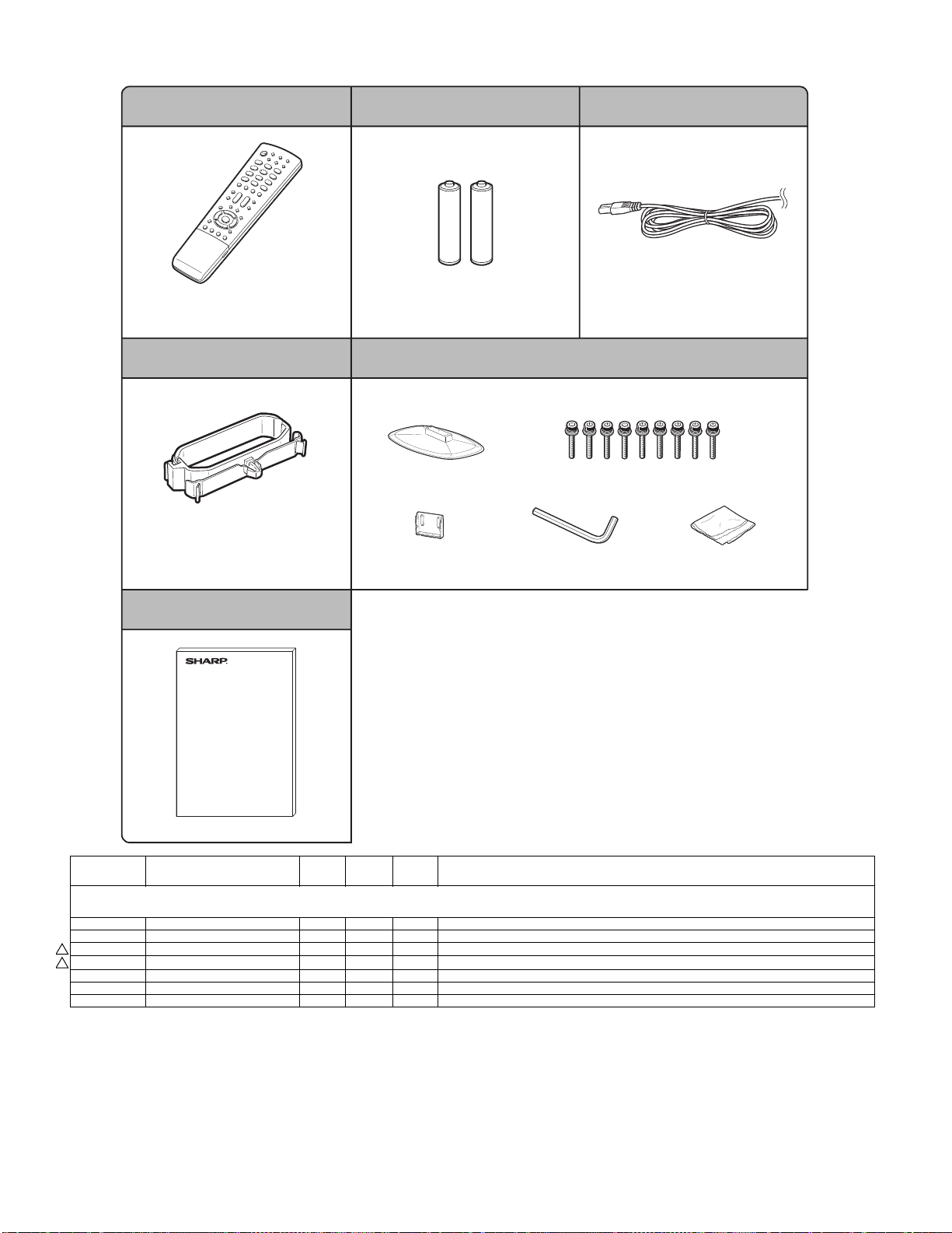
LC-32A33M
[8] SUPPLIED ACCESSORIES
Remote control unit "AAA" size battery (x 2) AC cord
X1 X2
Used with batteries inserted.
Cable clamp
X4
For bundling cables.
X3
Always use the AC cord supplied with
the TV.
Stand ass'y
X5
Stand base Short screws (x 9)
Stand post Hex key Cloth
Put all parts of the stand unit together and then attach it to the TV.
Operation manual
X6
NO. PARTS CODE
[8] SUPPLIED ACCESSORIES
X1 RRMCGA657WJSA AU N V Remote Control Unit
X2 Not Available - - "AAA" size battery
!
!
X3 QACCKA004WJPZ AM J AC Cord
X3 QACCBA076WJPZ AQ J AC Cord for Saudi Arabia
X4 LHLDWA173WJKZ AE J Cable Clamp
X5 CDAI-A441WJ02 BF N V Stand Ass'y
X6 TINS-D482WJZZ AL N V Operation Manual
PRICE
RANK
NEW
MARK
PAR T
DELIVERY
DESCRIPTION
22
Page 51

[9] PACKING PARTS (NOT REPLACEMENT ITEM)
S6
S5
S4
S4
S3
LC-32A33M
NO. PARTS CODE
S2
PRICE
RANK
NEW
MARK
PAR T
DELIVERY
S2
S1
[9] PACKING PARTS (NOT REPLACEMENT ITEM)
S1 SPAKCE010WJZZ - N - PACKING CASE
S2 SPAKXB829WJZZ - N - Bottom Pad
S3 SPAKPA611WJZZ - - WRAPPING PAPER
S4 SPAKXB828WJZZ - N - Top Pad
S5 SSAKA0128AJZZ - - POLYETHYLENE BAG
S6 SSAKA0005PEZZ - - A4 POLYETHYLENE BAG
S7 TLABV0182AJZZ - - NO.CARD
S7
DESCRIPTION
23
Page 52

LC32AA3M
CHAPTER 8. PRINTED WIRING BOARD
[1] MAIN UNIT
Side A
J
I
H
LC-32A33M
Service Manual
G
F
E
D
C
B
A
123456789
10 11 12 13 14 15 16 17 18 19 20 21
8 – 1
Page 53

LC-32A33M
Chip Parts Side A
J
R920
FL806
R941
C3640
C3680
R3670
C5201
R942
R3628
FL807
R864
R3686
C3641
R3671
L8112
R8101
R8103
FL808
R961
R3687
IC3607
C3642
R3630
C3681
R3642
L8111
FB806
R3690
R3685
R3634
R3636
R3638
R3665
SC8201
FL810
C879
C883
FL811
C876
FL809
C880
C872
C881
R971
R3688
R3684
C3645
C3655
C3656
C3657
C3658
C3659
C3660
R3672
C3661
L8110
R898
R896
C912
R892
R917
R970
C882
R871
R3689
C3646
Q3602
R3643
IC3603
D807
C885
C3679
R3683
L8109
R936
C890
FB804
C891
R1339
C914
P801
R3682
C915
C913
IC3605
C3683
R1340
C1331
R976
R960
R881
C3684
P3601
C8134
C8141
C8124
C8131
C8121
C8459
L2802
C1308
C8461
R8508
R8432
Q8403
C1313
IC8103
R8435
R8434
R8439
C8462
R8444
R8401
R8430
R8429
C2858
C2852
C2849
R1310
R1338
FB1303
C8464
C8420
R8431
C8470
R8438
R8442
R8441
R8422
R8423
Q1303
D1302
L1306
C8419
R8412
C8423
R8443
C8412
C8440
C8441
L1303L1304
D1306
C8119
C8123
C8117
R8408
C8417
R8411
C8439
R1308
R1309
C1314
C1320
C8103
R8409
R8410
R1313
C8116
R8141
C8416
R8405
C8414
R8440
R8437
R8433
R8436
Q8401
R8414
R8415
C8477
C1329
C1326
C1319
D1305
R8140
FL8101
C8428
R8406
C8405
IC8402
R8448
C8438
C1304
FB1304
C8115
R8145R8146
C8102
IC8102
R8115
C8426
C8478
C8404
C8430
D8405
R8418
R8413
C8410
R1342
C8104
R8147
R8121
R8506
R8445
R8449
C8418
R8416
C8106
C8108
R8426
R8424
C8411
C8421
IC8405
C8109
C8107
C8105
R8427
R8428
R8425
R8455
R8454
R8450
C8436
D8402
C8424
L2801
R2017
C8138
C8458
C8402
R8451
R8495
C8466
R8494
R8403
R8496
R8497
C8467
C8474
R2306
D2001
R2019
R2020
R8143
R8142
C8133
C8444
R8404
R8446
R8453
R8491
C8469
C8473
R8421
R8420
R8492
R8493
C8401
C8432
D8401
R2114
R2018
Q2001
C8132
C8113
R8120
R8130
R8134
R8135
R8136
R8137
IC8101
R8460
C8403
R8452
Q8402
C8433
C8425
FB2804
C2812
C2811
R2030
R2112
C2001
IC2002
R2009
C8135
FB8103
C8468
R8419
C8409
C8415
R2834
C2808
R8131
R8417
Q8408
R2025
R8106
R8122 R8123
R8124
R8126
R8128
R8507
R5284
P5203
L8107
L8108
L8114
C8127
C8125
R8148
C8128
C8122
C8120
C8118
FB4203
FB4204
FB4201
FB4202
C1330
C1322
D1304
FB1301
C4210
C1321
C4225
R1343
D1303
C4208
C4206
C4207
C2859
C2855
C2850
L2803
R1303
C1302
R1306
R1344
L1305
FB1302
C4211
R950R951
R865
C906
R959
C1318
C4219
R8505
R1341
R4208
R4224
R1312
C1327
C1324
C8129
C8144
C4213
D8406
L8402
D8407
D2804
Q2802
R1311
C4223
C8407
C1307
C8114
R4228
C4215
C8437
D2805
C2856
Q2801
C1309
IC1301
P1301
C8130
C8112
C4224
R4223
C8408
C8406
R8509
R8447
C1312
C1332
C8111
C4220
R8504
C8471
R8500
C2848
C1315
C8110
D8410
Q8405
C8422
D2807
D2803
C1311
C1325
C1317
LUG3406
I
H
D5208
G
P5205
C5205
R5203
Q5201
R5201
C5206
R5205
R5204
Q5202
R5214
R5211
C5208
R5212
Q5203
R5210
F
R460
R461
R459
E
R3421
R3406
D5201
R5206
R5215
R5209
R5207
C5211
C3503
C3502
R5208
R5216
R3563
D1903
J406
R3430
D1902
C3419
TH802
FB1901
C3504
Q3402
D1904
FB1902
R458
D1905
SC1901
R457
C423
Q3401
R1931
R1930
C1912
C1914
C1915
D1907
R3483
Q3416
R3491
R3490
C3505
R3401
R3422
R1913
D1906
C3495
R1917
R3408
R3418
R3562
C3501
R441
C1909
R3492
R3429
R443
C1913
Q1905
C3483
C3418
C1911
C1910
IC1903
R1919
IC1904
R3484
R3498
R1923
R3485
R3486
J404
J3401
C3493
R3489
R3405
Q1906
R1924
FB1903
D
D1908
D3402
Q3411
Q1907
C3401
R1909
R1907
R3402
R3407
Q1904
R1910
R1904
C1505
R1912
Q1903
R1905
R3417
C1504
IC1502
D1502
C1502
R1522
IC1503
C1503
IC1901
IC1902
R3473
R3497
R1908
R1906
Q3409
R3475
C3489
D3413
R1521
R1519
R3477
R1911
C3417
D3412
D3411
R3431
R3476
R3474
D3414
Q1902
R3456
R3435
J405
Q3405
R3425
R3412
SC404
R3454
R3459
D3410
R437
Q3404
R3472
R439
R3455
R3453
R3470
D3409
R3423
C3415
R3467
C3487
VA417
VA418
VA421
VA422
R3427
R3413
R3469
L411
VA419
L412
VA420
L413
VA423
L410
VA424
R3468
D3407
D3408
Q3408
R401
R416
R406
C403
R417
D3404
D3403
R3471
D401
D416
D3415
FB403
D3401
D3405
D3406
D408
R3409
SC403
FB404
C3413
R3403
C3455
C3485
R3410
R405
R402
D402 D403
D409
SC401
FB401
D414
D415
R408
R407
R3448
R3411
R3444
Q3403
R3446
R3437
Q3406
R3463
C3500
R3464
C3484
R3424
R3449
R3428
R3450
R3447
R3465
C
LUG3401
P2002
R3478
R3426
R3414
R3415
R3432
B
D3422
D3423
R3480
C3491
R3481
Q3410
R3479
R3482
VA409
VA410
VA413
VA414
R409
R3494
R3493
R3452
R3466
R3451
Q3407
L407
VA411
L408
VA412
L409
VA415
L406
VA416
R404
C402
R3495
R3442
R3457
C3425
C3424
R3458
C3426
R3462
C3412
R3461
C3427
R465
D410
IC401
SC402
R926
Q808
R8609
C806
R8616
R8608
C920
R925
R933
C919
R913
VA401
VA402
VA403
VA404
VA405
VA406
VA407
VA408
Q806
C801
L414
L403
L404
L405
R911
C917
R912
C918
R923
R935
R903
Q807
R921
R922
C803
TU3402
R8603
R8604
P8602P8603
IC1507
C8601
R8613
R1524
R8605
R1512
R1575
LUG3402
C8711
FB8701
C8704
C8724
C8730
LUG3404
Q8709
R8761
C8729
R8768
R8702
R8760
R8703
R8720
IC8702
C8726
R3544
R3555
R3554
C3463
R3593
C3476
C3478
R3550
R3529
C3473
C3474
R8706
C8723
R8735 R8736R8737
X8701
Q3413
L3405
D5205
C8727
C3670
C5230
R5245
D5206
R8732
C3669
P5204
C811
R8739
R8710
R8733
R8747
R5244
C5229
R8707
R8727
R8742
R8743R8744
R8730
Q8704
C8725
Q8705
R8746
C3469
C3466
R3434
C3603
C3665
R3651
R3650
C5228
IC808
R3488
R3606
R3603
C3606
C3604
C3664
D5207
R8745
IC3601
C3666
C3687
C899
R3433
R3608
R3610
R3607
IC3604
C3663
R879
R827
R826
R877
R816
R814
R880
R821
R882
R3611
R3609
IC806
C816
R817
R3487
Q3427
R3612
C3677
C3616
X3603
C3668
C3444
R3601
R972
FB802
FB801
C808
D803
C824
C823
C818
R876
C3462
C3602
C3601
R3617
C3608
C863
C904
C900
C820
C3453
C3626
C3627
R3625
C3607
R3618
C3619
C3667
IC807
C835
C839
C819
C901
C838
C834
C833
C817
R849
R851
C812
C826
R3664
C3439
C3672
R3620
R3621
C837
C825
R847
R3663
C3438
C3671
R3622
C836
R850
C902
C860
R954
R854
C841
C840
R853
C3428
C3615
C3673
C845
C842
C849
FL804
C848
C843
C853
D805
C3448
C3662
R3647
C3674
R3669
C3682
IC5202
R5213
R855
C847
FL802
FL801
R952
C850
R893
C844
FL803
C889
R867
Q810
C3635
R3623
IC3602
C3634
L5201
C855
C3636
R3681
C5210
FL805
C851
Q809
R3626
C5209
R8201
C3639
C5202
R8490
R8488
R8108
R8110
R8112
R8116
C8101
R8118
C8435
R8499
Q8410
R2829
R2830
D2802
D2806
R2105
R2089
R2088
R2069
C8434
D8404
D8408
R8456
IC2803
R2835
R2086
C2021
R2068
D5204
R8489
R8487
R8481
R8477
R8107
R8109
R8111
R8113
R8117
R8102
R8125
R8127
R8129
R8114
C2806
R2831
R2001
Q2020
L8106
C8447
R8462
R8457
R8458
R8461
R2832
Q2002
R2032
R2039
L8105
R8151
C8431
R2833
C2809
R2115
R2031
R2113
R8466
Q2803
R2026
C2015
Q2019
R2043
SC8202
L8104
IC8403
P8101
L8403
D8403
C8465
C2807
R2827
Q2804
R2081
R2027
R2010
IC2006
L8103
C8207
R8204
C8204C8205
R8203
R8205
L8401
Q8450
R2828
R2826
R2881
R2047
R2013
C2003
R2056
R8208
R8202
R8206
R8207
C8201
R2035
C2018
C2019
R8104
R2080
C8450
R8467
C8203
D8409
C2810
R2060
R2057
R2107
R2079
R8470
C8449
C8457
C8456
C8206
Q2821
R2058
R2064
C8451
R8473
C8210
C8209
R8212
R8238
IC8201
C8208
R8211
R8407
C8463
C8427
C8446
C8443
C8445
C8442
FB2803
FB2817
FB2801
R2882
Q2822
R2065
R2052
R2071
LUG3405
L8102
L8113
R8476
C8454
C8211
R8214
R8219
R8220
R8216
C8223
R8210
R8213
R8215
C8476
C2802
R2883
R2040
R8475
R8478
IC8404
C8215
C8214
R8221
R8209
R8225
C8222
IC8202
R8217
C8212
R8482
R8483
Q8414
L8101
R8480
R8486
R8223
R8224
R8228
R8230
R8234
R8231
C8448
R8471
Q8412
R8472
R8484
R8239
C8216
R8226
R8241
C8217
R8233
R8232
R8229
R8227
R8222
C8213
R8218
C8452
C8453
C8221
R8463
R8464
C8226
R8240
C8219
R8235
C8220
R8236
R8468
Q8411
Q8413
LUG3403
P2301
R2346
R8469
C8475
P2801
A
123456789
10 11 12 13 14 15 16 17 18 19 20 21
8 – 2
Page 54

LC-32A33M
Chip Parts Side B
J
C424
D405
Q410
Q409
C425
IC405
D413
R426
R449
R453
C410
R448
IC406
R467
R435
R451
R452
R450
R414
IC402
Q408
C405
R436
R447
R2041
R2095
R3445
R3597
D3424
C3499
R3443
R2099
R3496
Q3417
R3404
TH801
Q405
R430
R429
C8733
IC802
C3470
C805
R3551
C3465
C3468
C3461
R3605
C3605
D3604
R3680
C809
R3552
R3419
C3459
D3601
C861
C3479
R3558
R3604
C3686
IC3606
C3685
R8701
R5243
C3456
R3440
Q3414
R3553
Q3412
R3674
D3605
D3425
D8702
C8703
R8708
L3404
R3549
R3547
IC8701
R8738
R8729
R3561
R3675
C4205
C4203
R4202
X4201
IC2804
R2805
Q1301
R1307
C8330
R4213
R4201
C2804
R2878
C1301
R1302
R1301
D1309
R4214
R4226
R4207
R4206
R4204
R4225
C2814
C1306
R1305
D1307
D1308
D4202
IC4203
R4205
R4227
C4201
R2817
R2818
R1336
R1335
C8225
R4203
R2816
IC2801
C8227
I
C8331
C8460
C8455
R8485
R8479
H
R2344
C2320
C2317
R2335
C2316
C2315
R2336
C2318
R2323
R2315
R2319
R2316
G
C2319
R2343
IC2302
C2313
R2345
R2309
C2312
C2311
R2307
R2308
R2304
F
E
R8474
R8465
D8101
R8138
R8149
Q8101
R8139
R8144
R8512
R8516
R8515
R8514
C8413
R8459
R8511
C8479
R8510
D8411
Q8415
D
R2029
R2037
C2014
R2082
C2022
R2049
R2051
R2034
C2020
R2074
IC2009
FL2001
R2045
IC2001
R2083
R2066
R2059
R2072R2073
C
B
C2833
IC2805
R2846
C2801
C2813
C2832
C2840
C2838
R2847
C2844
R2879
D2801
FB2802
R2015
R2063
R2021
R2061
Q2025
R2077
R2036
R2109
R2108
R2044
R2110
R2024
R2111
R2014
R2033
R2055
R2050
R2012
R2016
R8513
R2093
R2347
C8429
Q2021
R2092
C8218
R2091
FB8106
C8228
C8137
FB8102
C8139
FB8104
C8143
C8136
C8140
FB8105
C8142
FB8101
R8402
C8472
C1310
C1323
C4222
C4221
R1317
C4218
C4217
R1321
R4222
R1322
R2819
R1319
C4216
R4221
R2821
C2843
R1325
C2846
R1320
C4214
IC4201
IC2802
R2810
C2841
R1326
R1333
C8126
R4212
R4218
R2815
C2837
C2836
R2812
FB2809
R1334
C4204
IC4202
C4212
C4202
C2815
FB2810
R2807
R2813
R2814
R2873
C2829
R2872
R2803
R2804
R2802
Q1302
C1316
C1328
R1337
C2831
Q2819
Q2820
C2827
C2830
R2806
C1305
D1301
R1328
Q1304
R957
C4209
R943
R944
R875
R904
R953
C893
C892
C895
C896
R873
R969
R968
R866
R828
R2809
C2805
C827
R878
C884
IC805
C832
FL812
C894
R869
X803
C8224
C887
R870
C886
R3640
R872
C888
R3657
R3645
R948
R949
R3652
R895
R947
C3649
R3668
R946
R962
C3654
R3632
R3641
R3667
D5209
C859
IC801
R890
R3653
R5226
R938R939
C3647
C3650
C3652
R858
R937
C3643
X802
R945
R975
C3632
R5286
D5202
R862
C903
C3637
R889
R859
R967
R3565
R3662
R5285
C868
R3564
C3433
C3434
C3429
R3661
C3437
C3440
C3441
C3442
C3443
C3630
R863
R3566
C3624
C3611
C3612
C3620
C3622
C8229
R861
R3567
C3613
C8202
R902
R860
C3450
C3610
R918
R901
C3430
C3431
C3451
C3452
C3629
C3628
C3609
C3617
C3618
R974
C810
C815
C830
R973
R919
R843
R841
C829
R924
C828
C813
C831
C822
C821
R852
R885
R886
R900
C3464
C3497
R914
R934
C898
R940
C3445
IC3409
C3498
IC804
R842
C802
R955
R3436
C3446
C3457
R3678
R832
R956
C3458
C3460
Q3606
R3460
C3449
C8712
C8728
C8717
C3477
Q3415
R3545
R3534
R3548
C8732
C8701
C8720
R3543
C3480
C3472
C3471
C8710
C8705
C3475
C3482
R3556R3557
R3530
R3560
R8715
C8721
R3596
C8706
R1509
R8714
IC8703
D8703
C8731
C8707
R8713
R8705
C8708
R8726
C8722
C8713
C8714
C8715
C8702
C8716
C8718
C8719
C8709
R1504
R1517
R1511
Q1517
IC1501
R1516
R1565
R1506
C1614
R1606
R1518
C1615
C1616
R1513
C1599
C1613
C1501
C1596
C1608
FB1509
C1597
R1505
R1501
FB1510
C1592
Q412
Q401
R1507
C1587
R1595
R464
R420
R421
Q402
R1622
Q1519
C1586
R1568
C1517
C1545
C1546
C1589
C1591
R8623
C8606
Q404
C406
C407
R8150
C1579
C1548
C1531
C1532
Q8603
R8625
IC403
R470
C1578
C1582
C1583
R8622
R424
R469
C1543
C1544
R1566
C1547
R8624
R423
R411
C1551
R1508
R422
R1593
R1580
R1503
Q1501
C8602
D411
R1515
Q8602
R8617
D412
Q403
R8620
R8621
C8603
R8618
R8614
D404
R433
R445
Q8601
R446
R8619
R8612
R412
R8607
C408
Q407
R434
D419
Q406
C409
R427
R428
R466
R432
IC404
R431
R468
D422
R413
C401
R403
D406
D423
R454
FB402
C404
R419
R418
A
123456789
10 11 12 13 14 15 16 17 18 19 20 21
8 – 4
Page 55

[2] R/C, LED/KEY UNIT
J
R/C, LED Unit Side-A
I
R/C, LED Unit Chip Parts Side-A
H
3
G
C107
R101
C102
SLD101
RMC101
D101
R132
IC101
C104
C105
R135
R136
R105
R102
D103
LC-32A33M
C103
IC102
R118
R116
C111
P101
R108
R107
R104
R109
R117
R137
Q104
Q102
Q103
D114
R106
R138
R126
R121
Q105
Q106
R127
R122
R124
Q107
R110
R123
D115
C108
C110
C101
R103
RMC102
R120
R119
D116
R140
R139
P102
F
KEY Unit Side-A
E
D
KEY Unit Chip Parts Side-A
C
S155
B
R153
D152
S154
S152
R151
D151
S151
R152
S153
R154
S156
S157
D155
P151
A
123456789
10 11 12 13 14 15 16 17 18 19 20
8 – 5
Page 56

LC-32A33M
LC32AA3M
CHAPTER 4. REMOVING OF MAJOR PARTS
Service Manual
[1] REMOVING OF MAJOR PARTS
1. REMOVING OF STAND ASS’Y AND REAR CABINET
1. Remove the 4 screws [1] and detach the Stand Ass’y.
2. Remove the 2 screws [2], 2 screws [3], 3 screws [4], 6 screws [5], and detach the Rear Cabinet.
Rear Cabinet
23
4
5
5
1
Stand Ass'y
4 – 1
Page 57

2. REMOVING OF SPEAKERS
1. Detach the Speaker-L and Speaker-R.
LC-32A33M
Speaker-R Speaker-L
4 – 2
Page 58

LC-32A33M
3. REMOVING OF CONNECTING CORDS
1. Remove all the connectors from all the PWBs.
KEY PWB Unit
MAIN PWB Unit
䬌䎵䎤䬍
䬌䎮䎰䬍
䬌䎮䎰䬍
䬌䎶䎦䎛䎕䎓䎔䬍 䬌䎶䎦䎛䎕䎓䎕䬍
䬌䎯䎥䬍
䬌䎳䎫䬍
䬌䎵䎤䬍
䬌䎶䎳䬍
POWER INVERTER PWB Unit
䬌䎯䎥䬍
䬌䎳䎫䬍
R/C, LED PWB Unit
4 – 3
Page 59

4. REMOVING OF PWB UNITS
1. Remove the 4 screws [1] and detach the POWER PWB Unit.
2. Remove the 2 screws [2] and 4 screws [3] and detach the MAIN PWB Unit.
3. Remove the 1 screw [4] and detach the R/C, LED PWB Unit.
4. Detach the KEY PWB Unit [5] from Front Cabinet.
LC-32A33M
3
2
MAIN PWB Unit
R/C, LED PWB Unit
KEY PWB Unit
1
5
POWER INVERTER PWB Unit
4
4 – 4
Page 60

LC-32A33M
5. REMOVING OF BOTTOM COVER, STAND ANGLE, PANEL ANGLES AND CENTER ANGLES
1. Remove the 2 screws [1] and 4screws [2] detach the Panel Angle Top-L/R and Panel Angle Bottom-L/R.
2. Remove the 1 screw [3] and detach the Bottom Cover.
3. Remove the 4 screws [4] and detach the Stand Angle.
4. Remove the 2 screws [5] and 10 screws [6] and detach the Center Angle.
5
6
Center Angle
1
Panel Angle Top-R
2
5
6
Center Angle
Panel Angle Top-L
1
2
Stand Angle
2
2
44
Panel Angle Bottom-R Panel Angle Bottom-L
3
Bottom Cover
4 – 5
Page 61

LC-32A33M
LC32AA3M
SAFETY PRECAUTION
Service Manual
IMPORTANT SERVICE SAFETY PRECAUTION
Service work should be performed only by qualified service technicians who are thoroughly familiar with all safety checks and the
servicing guidelines which follow:
WARNING
1. For continued safety, no modification of any circuit should be
attempted.
2. Disconnect AC power before servicing.
BEFORE RETURNING THE RECEIVER
(Fire & Shock Hazard)
Before returning the receiver to the user, perform the following
safety checks:
3. Inspect all lead dress to make certain that leads are not pinched,
and check that hardware is not lodged between the chassis and
other metal parts in the receiver.
4. Inspect all protective devices such as non-metallic control knobs,
insulation materials, cabinet backs, adjustment and compartment
covers or shields, isolation resistor-capacitor networks, mechanical
insulators, etc.
5. To be sure that no shock hazard exists, check for leakage current in
the following manner.
• Plug the AC cord directly into a 110 ~ 240 volt AC outlet.
• Using two clip leads, connect a 1.5k ohm, 10 watt resistor paralleled by a 0.15µF capacitor in series with all exposed metal cabinet
parts and a known earth ground, such as electrical conduit or electrical ground connected to an earth ground.
• Use an AC voltmeter having with 5000 ohm per volt, or higher, sensitivity or measure the AC voltage drop across the resistor.
• Connect the resistor connection to all exposed metal parts having a
return to the chassis (antenna, metal cabinet, screw heads, knobs
and control shafts, escutcheon, etc.) and measure the AC voltage
drop across the resistor.
All checks must be repeated with the AC cord plug connection
reversed. (If necessary, a non polarized adaptor plug must be used
only for the purpose of completing these checks.)
Any reading of 0.74 Vrms (this corresponds to 0.5 mA rms AC.) or
more is excessive and indicates a potential shock hazard which
must be corrected before returning the monitor to the owner.
DVM
AC SCALE
1.5k ohm
10W
0.15µF
TEST PROBE
TO EXPOSED
METAL PARTS
CONNECT TO
KNOWN EARTH
GROUND
///////////////////////////////////////////////////////////////////////////////////////////////////////////////////////////////////////////////////////////////////////////////////////////////////////////////////////////////////////////
SAFETY NOTICE
Many electrical and mechanical parts in LCD color television have
special safety-related characteristics.
These characteristics are often not evident from visual inspection, nor
can protection afforded by them be necessarily increased by using
replacement components rated for higher voltage, wattage, etc.
Replacement parts which have these special safety characteristics are
identified in this manual; electrical components having such features
are identified by " " and shaded areas in the Replacement Parts
Lists and Schematic Diagrams.
For continued protection, replacement parts must be identical to those
used in the original circuit.
The use of a substitute replacement parts which do not have the same
safety characteristics as the factory recommended replacement parts
shown in this service manual, may create shock, fire or other hazards.
///////////////////////////////////////////////////////////////////////////////////////////////////////////////////////////////////////////////////////////////////////////////////////////////////////////////////////////////////////////
i
Page 62

LC-32A33M
Precautions for using lead-free solder
Employing lead-free solder
• “All PWBs” of this model employs lead-free solder. The LF symbol indicates lead-free solder, and is attached on the PWBs and service manuals.
The alphabetical character following LF shows the type of lead-free solder.
Example:
L Fa
Indicates lead-free solder of tin, silver and copper.
Indicates lead-free solder of tin, silver and copper.
L F a/a
Using lead-free wire solder
• When fixing the PWB soldered with the lead-free solder, apply lead-free wire solder. Repairing with conventional lead wire solder may cause damage or accident due to cracks.
As the melting point of lead-free solder (Sn-Ag-Cu) is higher than the lead wire solder by 40 °C, we recommend you to use a dedicated soldering
bit, if you are not familiar with how to obtain lead-free wire solder or soldering bit, contact our service station or service branch in your area.
Soldering
• As the melting point of lead-free solder (Sn-Ag-Cu) is about 220 °C which is higher than the conventional lead solder by 40 °C, and as it has poor
solder wettability, you may be apt to keep the soldering bit in contact with the PWB for extended period of time. However, Since the land may be
peeled off or the maximum heat-resistance temperature of parts may be exceeded, remove the bit from the PWB as soon as you confirm the
steady soldering condition.
Lead-free solder contains more tin, and the end of the soldering bit may be easily corroded. Make sure to turn on and off the power of the bit as
required.
If a different type of solder stays on the tip of the soldering bit, it is alloyed with lead-free solder. Clean the bit after every use of it.
When the tip of the soldering bit is blackened during use, file it with steel wool or fine sandpaper.
• Be careful when replacing parts with polarity indication on the PWB silk.
Lead-free wire solder for servicing
Part No. Description Code
ZHNDAi123250E J φ0.3mm 250g (1roll) BL
ZHNDAi126500E J φ0.6mm 500g (1roll) BK
ZHNDAi12801KE J φ1.0mm 1kg (1roll) BM
ii
Page 63

LC-32A33M
LC32AA3M
CHAPTER 1. SPECIFICATIONS
[1] SPECIFICATIONS
Service Manual
Model
Item
LCD panel
Resolution 1,049,088 pixels (1366 x 768)
Video Colour System
TV
Function
Brightness
Viewing angles
Audio amplifier 10W x 2
Speakers 10x4cm 2pcs
Terminals Rear
OSD language
Power Requirement
Power Consumption
Weight
Operating Temperature 0°C - 40°C
TV-Standard
Receiving
Channel
TV-Tuning System
STEREO/BILINGUAL
VHF/UHF
CATV
Antenna input
INPUT 1
INPUT 2
INPUT 3
INPUT 4 HDMI (HDMI input) (480P, 576P, 720P/50Hz, 720P/60Hz, 1080I/50Hz, 1080I/60Hz)
INPUT 5
MONITOR OUT VIDEO out, AUDIO out
RS-232C 9 pin D-sub male connector
without stand 10.5 kg
with stand
(PC input)
LC-32A33M
32"(800 mm) Advanced Super View &
BLACK TFT LCD
PAL/SECAM/NTSC 3.58/NTSC 4.43/PAL 60
PAL: B/G, D/K, I SECAM: B/G, D/K, K/K
44.25 - 863.25 MHz
S1 - 41ch (including Hyperband)
Auto Preset 99 ch
NICAM: B/G, I, D/K A2 stereo: B/G
450 cd/m
H : 176º V : 176º
UHF/VHF 75 DIN type
VIDEO in, AUDIO in, S-VIDEO in,
COMPONENT in (480I, 576I, 480P, 576P, 720P/50Hz, 720P/60Hz, 1080I/50Hz, 1080I/60Hz)
VIDEO in, AUDIO in,
COMPONENT in (480I, 576I, 480P, 576P, 720P/50Hz, 720P/60Hz, 1080I/50Hz, 1080I/60Hz)
HDMI (HDMI input) (480P, 576P, 720P/50Hz, 720P/60Hz, 1080I/50Hz, 1080I/60Hz)
AUDIO in
15 pin mini D-sub, AUDIO in (Ø 3.5 mm jack)
English/Simplified Chinese/Traditional Chinese/Arabic
AC 110 - 240 V, 50/60 Hz
133 W (0.7 W Standby)
12.5 kg
2
1
NTSC: M
As a part of policy of continuous improvement, SHARP reserves the right to make design and specification changes for product
improvement without prior notice. The performance specification figures indicated are nominal values of production units. There
may be some deviations from these values in individual units.
1 – 1
Page 64

LC-32A33M
LC32AA3M
CHAPTER 6. TROUBLESHOOTING TABLE
Service Manual
[1] TROUBLESHOOTING TABLE
No power (front LED failure to light up) or no startup (front LED failure to turn from red to green)
Is the AC cord connector tightly connected to the set? NO Reconnect the AC cord tightly and turn on the power again.
YES
Is the output voltage at pin (5) of P2801 (BU+5V line) as specified?
YES
Are the wire harnesses and other cables properly connected in
the set?
YES
Is there the PS ON and signal input at pin (10) of P2801 (PS ON
line)?
YES
Is the output voltage of each pin on P2801 as prescribed?
Pin 1, 2, 3 and 4 13V
Pins 11 5V
NO Replace the power unit
32 inch (RUNTKA419WJQZ)
NO Reconnect the wire harnesses and other cables properly in the
set.
NO Check the PS ON signal line.
NO Replace the power unit
32 inch (RUNTKA419WJQZ)
YES
Are the DC/DC converter outputs and the output voltages along
the control lines as specified?
1) 5V (IC2803 etc.)
2) 4V (IC2804 etc.)
3) 3.3V (IC2804 etc.)
4) 9V (IC2801 etc.)
NO Check the DC/DC converters and the control lines. Replace
defective parts as required.
6 – 1
Page 65

LC-32A33M
With <Video, S-video> signal input No video on screen (1)
No external input video on screen <INPUT 1>
Is INPUT 1 selected on the input select menu screen? NO Select INPUT 1 on the input select menu screen to pick up the
right input signal.
YES
Is there the video signal input at pin (6) of IC3409 (AV SWITCH)? NO Check the line between pin (12) of J3404 and pin (6) of IC3409.
YES
<Video signal> Is there the video signal output at pin (16) of
IC3409?
<S-video signal> Are there the Y and C signal outputs at pins
(24) and (26) of IC3409, respectively?
YES
<Video signal> Is there the video signal input at U2 pin of IC801? NO <Video signal> Check its peripheral circuits.
<S-video signal> Are there the Y and C signal inputs at P1 pin
and K1 pin of IC801, respectively?
NO Check IC3409 and its peripheral circuits.
<S-video signal> Check its peripheral circuits for the C signal,
and its peripheral circuits for the Y signal.
YES
Are signals output from the pins P22, P23, R22, R23, T22, T23,
U22, U23, V22, V23, W22 and W23 of IC801 normally?
YES
Check LVDS cable, LCD controller (incl. panel) and their periph-
eral circuits.
NO Check IC801 and its peripheral circuits.
6 – 2
Page 66

LC-32A33M
With <Video> signal input No video on screen (2)
No external input video on screen <INPUT 2>
Is INPUT 2 selected on the input select menu screen? NO Select INPUT 2 on the input select menu screen to pick up the
right input signal.
YES
Is there the video signal input at pin (56) of IC3409
(AV SWITCH)?
YES
<Video signal> Is there the video signal output at pin (16) of
IC3409?
YES
<Video signal> Is there the video signal input at U2 pin of IC801? NO <Video signal> Check its peripheral circuits.
YES
Are signals output from the pins P22, P23, R22, R23, T22, T23,
U22, U23, V22, V23, W22 and W23 of IC801 normally?
NO Check the line between pin (12) of J3403 and pin (56) of IC3409.
NO Check IC3409 and its peripheral circuits.
NO Check IC801 and its peripheral circuits.
YES
Check LVDS cable, LCD controller (incl. panel) and their peripheral circuits.
6 – 3
Page 67

LC-32A33M
With <Component> signal input No video on screen (3)
No external input video on screen <INPUT 2>
Is INPUT 1 selected on the input select menu screen? NO Select INPUT 2 on the input select menu screen to pick up the
right input signal.
YES
Are there the Y, Pb and Pr signal inputs at pins (40), (38) and
(36) of IC3409, respectively?
YES
Is input waveform of IC801 normal?
Y=U1pin, Sync=J2pin
Pb=L1pin, Pr=R1pin
YES
Are there the signal outputs at pins U22, U23, V22, V23, W22,
W23, P22, P23, R22, R23, T22, T23 of IC801, respectively?
YES
Check LVDS cable, LCD controller (incl. panel) and their peripheral circuits.
NO Check the line between pins (7)/(8)/(9) of J3403 and pins (40)/
(38)/(36) of IC3409.
NO Check IC3409 and its peripheral circuits.
NO Check IC801 and its peripheral circuits.
With <Component> signal input No video on screen (4)
No external input video on screen <INPUT 1>
Is INPUT 2 selected on the input select menu screen? NO Select INPUT 1 on the input select menu screen to pick up the
YES
Are there the Y, Pb and Pr signal inputs at pins (34), (32) and
(30) of IC3409, respectively?
YES
Is input waveform of IC801 normal?
Y=U1pin, Sync=J2pin
Pb=L1pin, Pr=R1pin
YES
Are there the signal outputs at pins U22, U23, V22, V23, W22,
W23, P22, P23, R22, R23, T22, T23 of IC801, respectively?
YES
Check LVDS cable, LCD controller (incl. panel) and their periph-
eral circuits.
NO Check the line between pins (7)/(8)/(9) of J3404 and pins (34)/
NO Check IC3409 and its peripheral circuits.
NO Check IC801 and its peripheral circuits.
right input signal.
(32)/(30) of IC3409.
6 – 4
Page 68

LC-32A33M
With <HDMI> signal input No video on screen (5)
No external input video on screen <INPUT 3>, <INPUT 4>
Is INPUT 3, INPUT 4 selected on the input select menu screen? NO Select INPUT 3 or INPUT 4 on the input select menu screen to
pick up the right input signal.
YES
Are there the signal inputs from the HDMI (SC404, SC403)
connector to the following input terminals of IC8702 (pin (16),
(17), (19), (20), (22), (23), (25), (26), (31), (32)).
YES
Are there the clock, H, V, Data signal outputs at pins (71) - (80),
(83) - (92), (96), (98), (99), (104) - (113) of IC8702, respectively?
YES
Are waveforms of the clock, H, V, and Data terminals of
IC801 normal?
NO With an HDMI device connected, is IC406, IC404 (EEPROM)
accessed by I2C and is the DDC I2C CLOCK/DATA data read?
NO
Check IC406, IC404 and their peripheral circuits.
NO Check IC8702 and their peripheral circuits.
NO Check IC801 and its peripheral circuits.
YES
Are there the signal outputs at pins U22, U23, V22, V23, W22,
W23, P22, P23, R22, R23, T22, T23 of IC801, respectively?
YES
Check LVDS cable, LCD controller (incl. panel) and their peripheral circuits.
No video on screen (6)
No video in the UHF/VHF reception
Is the IF output from the tuner (TU3402) as specified? NO Check TU3402 and its peripheral circuits.
YES
Is there the video signal input at pin (14) of IC3409 (AV
SWITCH)?
YES
Is there the video signal output at pin (16) of IC3409? NO Check IC3409 and its peripheral circuits.
NO Check IC801 and its peripheral circuits.
NO Check the line between TU3402 and IC3409.
YES
<Video signal> is there the video signal input at U2 pin of IC801? NO <Video signal> Check its peripheral circuits.
YES
Are signals output from the pins P22, P23, R22, R23, T22, T23,
U22 , U23, V22, V23, W22 and W23 of IC801 normaly?
YES
Check LVDS cable, LCD controller (incl. panel) and their peripheral circuits.
NO Check IC801 and its peripheral circuits.
6 – 5
Page 69
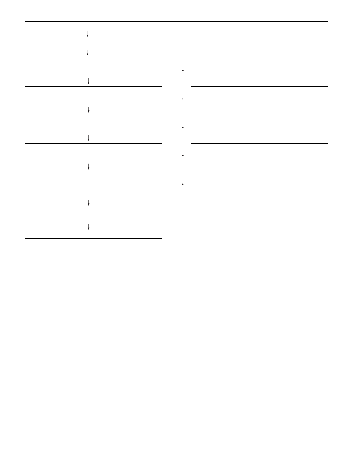
No audio heard (1)
No sound in the UHF/VHF reception.
Is the IF output from the tuner pin (14) of TU3402 as specified? NO Check TU3402 and its peripheral circuits.
YES
Is the SIF signal input at A21 pin of IC801 as specified? NO Check Q3414, Q3415 and their peripheral circuits.
YES
Are audio signals from the pins B23 and D23 of IC801 as
prescribed?
YES
Is there the L-ch audio signal output at pins (51) of IC3602? NO Check IC3602 and its peripheral circuits.
Is there the R-ch audio signal output at pins (52) of IC3602?
YES
Is there the L-ch audio signal output at pins (39), (44) of IC1301
(AMP)?
Is there the R-ch audio signal output at pins (17), (20) of IC1301
(AMP)?
NO Check IC801 and their peripheral circuits.
NO Check IC1301 and its peripheral circuits.
LC-32A33M
YES
Are audio signals of L-ch and R-ch output from the pins (1)/(2)
and (3)/(4) of P1301 normally?
YES
Check the speakers and their peripheral circuits.
6 – 6
Page 70

LC-32A33M
No audio heard (2)
No external audio heard
<INPUT 2>
Is there the L-ch audio signal input from pin (11) of input terminal
J3403 to pin (43) of IC3602?
Is there the R-ch audio signal input from pin (10) of input terminal
J3403 to pin (44) of IC3602?
<INPUT 1>
Is there the L-ch audio signal input from pin (11) of input terminal
J3404 to pin (46) of IC3602?
Is there the R-ch audio signal input from pin (10) of input terminal
J3404 to pin (47) of IC3602?
YES
Is there the L-ch audio signal output at pins (39), (44) of IC1301
(AMP)?
Is there the R-ch audio signal output at pins (17), (20) of IC1301
(AMP)?
YES
Are audio signals of L-ch and R-ch output from the pins (1)/(2)
and (3)/(4) of P1301 normally?
YES
Check the speakers and their peripheral circuits.
NO Check IC3602 and its peripheral circuits.
NO Check IC1301 and its peripheral circuits.
6 – 7
Page 71

No audio heard (3)
No audio signal at the monitor audio output terminal.
Is there the L-ch audio signal output at pin (86) of IC3602? NO Check IC3602 and its peripheral circuits.
Is there the R-ch audio signal output at pin (87) of IC3602?
YES
Does the audio mute circuit function?
(Q3401, Q3402 and Q3417)
YES
Check the monitor audio output terminal (J3402) and its
peripheral circuits.
No audio heard (4)
No sound heard from the headphone.
Is there the audio signal output at pins (91) (L-ch) and (93) (R-ch)
of IC3602?
NO Check Q3401, Q3402, Q3403 and their peripheral circuits.
LC-32A33M
Is there the L-ch audio signal output at pin (1) of IC3604
(H/P AMP)?
Is there the R-ch audio signal output at pin (7) of IC3604
(H/P AMP)?
YES
Check J406 and it peripheral circuits, as well as the headphone
jack line.
NO Is the mute signal input at pin (2) of IC3604 as specified?
6 – 8
Page 72

LC-32A33M
No audio heard (5)
No HDMI sound heard.
(INPUT 3, INPUT 4 *INPUT 4 is digital audio.)
Does the HDMI image appear on screen? NO Refer to “<INPUT 3, INPUT 4> in No external image on screen
YES
No audio output from INPUT 3 and INPUT 4. NO Check if the EDID data of IC406 (INPUT 4) or IC404 (INPUT 3) is
YES
Are waveforms of the pins (120) - (124) of IC8702 output
normally?
YES
Are output waveforms of the audio output pins B23 and D23 of
IC801 normal?
NO Check peripheral circuits of IC8702.
NO Check peripheral circuits of IC801.
(HDMI)”.
normal.
YES
Check peripheral circuits of IC406 and IC404.
YES
Are audio signals of L-ch and R-ch input in to the pins (46) and
(47) for volume, equalizer and sound of IC3602 normally and
output from the pins (84) and (85) normally?
YES
Are there the L-ch and R-ch audio signal outputs at pins (39),
(44) and (17), (20) of IC1301 (AMP), respectively?
YES
Are there the L-ch and R-ch audio signal inputs at pins (1), (2)
and (3), (4) of P1301, respectively?
NO Check peripheral circuits of IC3602.
NO Check IC1301 and its peripheral circuits.
6 – 9
Page 73

No audio heard (6)
No sound from the HDMI sound input terminal.
(INPUT 3 analog audio)
YES
Is there the L-ch audio signal input from pin (2) of external input
terminal J404 (HDMI AUDIO IN) to pin (57) of IC3602?
Is there the R-ch audio signal input from pin (3) of external input
terminal J404 (HDMI AUDIO IN) to pin (58) of IC3602?
YES
Are there the L-ch and R-ch audio signal outputs at pins (84) and
(85) of IC3602, respectively?
YES
Are there the L-ch and R-ch audio signal outputs at pins (39),
(44) and (17), (20) of IC1301 (AMP), respectively?
YES
Are there the L-ch and R-ch audio signal inputs at pins (1), (2)
and (3), (4) of P1301, respectively?
LC-32A33M
NO Check IC3602 and its peripheral circuits.
NO Check IC1301 and its peripheral circuits.
No audio heard (7)
No PC audio output
YES
Pin (2) of J405: Is L-ch input into the pin (60) of IC3602?
Pin (3) of J405: Is R-ch input into the pin (61) of IC3602?
YES
Are there the L-ch and R-ch audio signal outputs at pins (84) and
(85) of IC3602, respectively?
YES
Are there the L-ch and R-ch audio signal outputs at pins (39),
(44) and (17), (20) of IC1301 (AMP), respectively?
YES
Are there the L-ch and R-ch audio signal inputs at pins (1), (2)
and (3), (4) of P1301, respectively?
NO Check IC3602 and its peripheral circuits.
NO Check IC1301 and its peripheral circuits.
6 – 10
Page 74

LC-32A33M
- MEMO -
6 – 11
 Loading...