

Page 1

LC-20B6U-S
SERVICE MANUAL
S64T8LC20B6US
LCD COLOR TELEVISION
MODEL
In the interests of user-safety (Required by safety regulations in some countries) the set should be restored
to its original condition and only parts identical to those specified should be used.
CONTENTS
» IMPORT ANT SER VICE SAFETY PRECAUTION.........................................................................................2
» SPECIFICATIONS ........................................................................................................................................5
» OPERATION MANUAL ............................................................................................................... ..................6
» DIMENSIONS ...............................................................................................................................................8
» REMOVING OF MAJOR P ARTS ..................................................................................................................9
» ADJUSTING PROCEDURE OF EACH SECTION .....................................................................................14
» TROUBLE SHOOTING TABLE ..................................................................................................................28
» MAJOR IC INFORMATIONS ......................................................................................................................33
» CHASSIS LAYOUT .....................................................................................................................................48
» BLOCK DIAGRAM......................................................................................................................................50
» OVERALL WIRING DIAGRAM ...................................................................................................................52
» DESCRIPTION OF SCHEMATIC DIAGRAM .............................................................................................54
» SCHEMATIC DIAGRAM .............................................................................................................................55
» PRINTED WIRING BOARD ASSEMBLIES................................................................................................81
» REPLACEMENT PARTS LIST.................................................................................................................... 90
» PACKING OF THE SET............................................................................................................................103
LC-20B6U-S
Page
SHARP CORPORATION
This document has been published to be used for
after sales service only.
The contents are subject to change without notice.
Page 2

LC-20B6U-S
2
3
3
IMPORTANT SERVICE SAFETY PRECAUTION
Ë
Service work should be performed only by qualified service technicians who are thoroughly familiar with all safety checks and the servicing guidelines which follow:
WARNING
1. For continued safety, no modification of any circuit
should be attempted.
2. Disconnect AC power before servicing.
CAUTION: FOR CONTINUED
PROTECTION AGAINST A RISK OF
FIRE REPLACE ONL Y WITH SAME
TYPE F3701 (2.0A, 250V), F3702
A V
(1.25A, 250V), AND F6701 (6.3A,
250V) FUSE.
BEFORE RETURNING THE RECEIVER
(Fire & Shock Hazard)
Before returning the receiver to the user, perform
the following safety checks:
1. Inspect all lead dress to make certain that leads are
not pinched, and check that hardware is not lodged
between the chassis and other metal parts in the
receiver.
2. Inspect all protective devices such as non-metallic
control knobs, insulation materials, cabinet backs,
adjustment and compartment covers or shields, isolation
resistor-capacitor networks, mechanical insulators, etc.
3. To be sure that no shock hazard exists, check for
leakage current in the following manner.
• Plug the AC cord directly into a 110~240 volt AC outlet,
and connect the DC power cable into the receiver's DC
jack. (Do not use an isolation transformer for this test).
• Using two clip leads, connect a 1.5k ohm, 10 watt
resistor paralleled by a 0.15µF capacitor in series with
all exposed metal cabinet parts and a known earth
ground, such as electrical conduit or electrical ground
connected to an earth ground.
• Use an AC voltmeter having with 5000 ohm per volt, or
higher, sensitivity or measure the AC voltage drop
across the resistor.
• Connect the resistor connection to all exposed metal
parts having a return to the chassis (antenna, metal
cabinet, screw heads, knobs and control shafts,
escutcheon, etc.) and measure the AC voltage drop
across the resistor.
All checks must be repeated with the AC cord plug
connection reversed. (If necessary, a nonpolarized
adaptor plug must be used only for the purpose of
completing these checks.)
Any reading of 0.75V peak (this corresponds to 0.5 mA.
peak AC.) or more is excessive and indicates a potential
shock hazard which must be corrected before returning
the monitor to the owner.
DVM
AC SCALE
1.5k ohm
10W
0.15 µF
TEST PROBE
TO EXPOSED
METAL PARTS
CONNECT TO
KNOWN EARTH
GROUND
234567890123456789012345678901212345678901234567890123456789012123456789012345678901234567890121
SAFETY NOTICE
Many electrical and mechanical parts in LCD television
have special safety-related characteristics.
These characteristics are often not evident from visual
inspection, nor can protection afforded by them be
necessarily increased by using replacement components
rated for higher voltage, wattage, etc.
Replacement parts which have these special safety
characteristics are identified in this manual; electrical
and shaded areas in the
Schematic Diagrams
For continued protection, replacement parts must be
identical to those used in the original circuit.
The use of a substitute replacement parts which do not
have the same safety characteristics as the factory
recommended replacement parts shown in this service
manual, may create shock, fire or other hazards.
components having such features are identified by " å"
2345678901234567890123456789012123456789012345678901234567890121234567890123456789012345678901212
2345678901234567890123456789012123456789012345678901234567890121234567890123456789012345678901212
2
Replacement Parts Lists
.
and
Page 3

LC-20B6U-S
2
2
2
DVM
ECHELLE CA
1.5k ohm
10W
0.15 µF
SONDE D'ESSAI
AUX PIECES
METALLIQUES
EXPOSEES
BRANCHER A UNE
TERRE CONNUE
PRECAUTIONS A PRENDRE LORS DE LA REPARATION
Ë
Ne peut effectuer la réparation qu' un technicien spécialisé qui s'est parfaitement
accoutumé à toute vérification de sécurité et aux conseils suivants.
AVERTISSEMENT
conduite électrique ou une prise de terre branchée à la
terre.
1. N'entreprendre aucune modification de tout circuit.
C'est dangereux.
2. Débrancher le récepteur avant toute réparation.
PRECAUTION: POUR LA
PROTECTION CONTINUE
CONTRE LES RISQUES
D'INCENDIE, REMPLACER LE
A V
FUSIBLE P AR UN FUSIBLE DE
MEME TYPE F3701 (2.0A, 250V),
F3702 (1.25A, 250V) F6701 (6.3A,
250V).
• Utiliser un voltmètre CA d'une sensibilité d'au moins
5000Ω/V pour mesurer la chute de tension en travers
de la résistance.
• Toucher avec la sonde d'essai les pièces métalliques
exposées qui présentent une voie de retour au châssis
(antenne, coffret métallique, tête des vis, arbres de
commande et des boutons, écusson, etc.) et mesurer
la chute de tension CA en-travers de la résistance.
T outes les vérifications doivent être refaites après avoir
inversé la fiche du cordon d'alimentation. (Si nécessaire,
une prise d'adpatation non polarisée peut être utilisée
dans le but de terminer ces vérifications.)
Tous les courants mesurés ne doivent pas dépasser
VERIFICA TIONS CONTRE L'INCEN-DIE ET
LE CHOC ELECTRIQUE
Avant de rendre le récepteur à l'utilisateur, effectuer
0,5 mA.
Dans le cas contraire, il y a une possibilité de choc
électrique qui doit être supprimée avant de rendre le
récepteur au client.
les vérifications suivantes.
1. Inspecter tous les faisceaux de câbles pour s'assurer
que les fils ne soient pas pincés ou qu'un outil ne soit
pas placé entre le châssis et les autres pièces
métalliques du récepteur.
2. Inspecter tous les dispositifs de protection comme les
boutons de commande non-métalliques, les isolants,
le dos du coffret, les couvercles ou blindages de réglage
et de compartiment, les réseaux de résistance-capacité,
les isolateurs mécaniques, etc.
3. S'assurer qu'il n'y ait pas de danger d'électrocution en
vérifiant la fuite de courant, de la facon suivante:
• Brancher le cordon d'alimentation directem-ent à une
prise de courant de 110-240V. (Ne pas utiliser de
transformateur d'isolation pour cet essai).
• A l'aide de deux fils à pinces, brancher une résistance
de 1.5kΩ 10 watts en parallèle avec un condensateur
de 0.15µF en série avec toutes les pièces métalliques
exposées du coffret et une terre connue comme une
234567890123456789012345678901212345678901234567890123456789012123456789012345678901234567890121
AVIS POUR LA SECURITE
De nombreuses pièces, électriques et mécaniques, dans
les téléviseurs présentent des caractéristiques spéciales
relatives à la sécurité, qui ne sont souvent pas évidentes
à vue. Le degré de protection ne peut pas être
nécessairement augmentée en utilisant des pièces de
remplacement étalonnées pour haute tension,
puissance, etc.
Les pièces de remplacement qui présentent ces
caractéristiques sont identifiées dans ce manuel; les
pièces électriques qui présentent ces particularités sont
234567890123456789012345678901212345678901234567890123456789012123456789012345678901234567890121
234567890123456789012345678901212345678901234567890123456789012123456789012345678901234567890121
identifiées par la marque " å " et hachurées dans la
liste des pièces de remplacement et les diagrammes
schématiques.
Pour assurer la protection, ces pièces doivent être
identiques à celles utilisées dans le circuit d'origine.
L'utilisation de pièces qui n'ont pas les mêmes
caractéristiques que les pièces recommandées par
l'usine, indiquées dans ce manuel, peut provoquer des
électrocutions, incendies, radiations X ou autres
accidents.
3
Page 4

LC-20B6U-S
Precautions for using lead-free solder
1 Employing lead-free solder
"All PWBs" of this model employs lead-free solder. The LF symbol indicates lead-free solder, and is attached on
the PWBs and service manuals. The alphabetical character following LF shows the type of lead-free solder.
Example:
L Fa
Indicates lead-free solder of tin, silver and copper.
2 Using lead-free wire solder
When fixing the PWB soldered with the lead-free solder, apply lead-free wire solder. Repairing with conventional
lead wire solder may cause damage or accident due to cracks.
As the melting point of lead-free solder (Sn-Ag-Cu) is higher than the lead wire solder by 40°C, we recommend
you to use a dedicated soldering bit, if you are not familiar with how to obtain lead-free wire solder or soldering bit,
contact our service station or service branch in your area.
3 Soldering
As the melting point of lead-free solder (Sn-Ag-Cu) is about 220°C which is higher than the conventional lead
solder by 40°C, and as it has poor solder wettability, you may be apt to keep the soldering bit in contact with the
PWB for extended period of time. However, Since the land may be peeled off or the maximum heat-resistance
temperature of parts may be exceeded, remove the bit from the PWB as soon as you confirm the steady soldering
condition.
Lead-free solder contains more tin, and the end of the soldering bit may be easily corroded. Make sure to turn on
and off the power of the bit as required.
If a different type of solder stays on the tip of the soldering bit, it is alloyed with lead-free solder . Clean the bit after
every use of it.
When the tip of the soldering bit is blackened during use, file it with steel wool or fine sandpaper.
Be careful when replacing parts with polarity indication on the PWB silk.
Lead-free wire solder for servicing
Part No, ★ Description Code
ZHNDAi123250E J φ0.3mm 250g(1roll) BL
ZHNDAi126500E J φ0.6mm 500g(1roll) BK
ZHNDAi12801KE J φ1.0mm 1kg(1roll) BM
4
Page 5

SPECIFICATIONS
Items
LCD panel 20.1'' Advanced Super View & BLACK TFT LCD
Number of dots 2,359,296 dots XGA
Video color systems N358, N443, PAL, PAL-M, PAL-N, SECAM, PAL-60
TV Standard (CCIR) NTSC/PAL-M/PAL-N
TV function
TV T uning System
PLL 181 ch.
STEREO MTS+SAP
CATV 125 ch.
Y/C FILTER 3D Y/C FILTER
Brightness 430 cd/m
2
Viewing angles H: 170° V: 170°
Audio amplifier 2.1 W × 2
Speakers ø2.1 in. (ø5.7 cm), 2 pcs.
COMPONENT1
COMPONENT1-IN, AUDIO-IN
COMPONENT2/AV1 COMPONENT2/AV1-IN, AUDIO-IN, S-VIDEO-IN
Terminals AV-IN2 AV-IN2/AV-OUT
PC-IN PC Connector: 15-pin mini D-sub PC AUDIO: Mini-jack for stereo (ø3.5 mm)
Antenna F-Type
Headphone Mini-jack for stereo (ø3.5 mm)
OSD language English/Spanish/French
Power supply DC 12V, AC 110-240V, 50/60Hz (AC adapter), AC 110-125V (AC cord)
Power consumption 81 W (0.5 W standby) :AC 120V
71 W: DC 12V
Weight 19.0 lbs. (8.6 kg), w/o accessories
Accessories Remote control, Battery (× 2), Antenna cable, AC adapter, RGB cable, AC cord,
Cable holder, Cable clamp, Operation manual, Registration card
Model
LC-20B6U
Ë As a part of policy of continuous improvement, SHARP reserves the right to make design and specification changes for product improve-
ment without prior notice. The performance specification figures indicated are nominal values of production units. There may be some
deviations from these values in individual units.
LC-20B6U-S
5
Page 6

LC-20B6U-S
Part Names of Main Unit
Controls
• INPUT, CH (
)/(
), VOL (–)/(+) and MENU on the main unit have the same functions as the same buttons on the remote control.
Fundamentally, this operation manual provides a description based on operation using the remote control.
HEADPHONE jack
Plug the headphone mini-plug into the Headphone
jack located on the front of the main unit.
OPC (Optical Picture Control) sensor
Remote sensor
OPC indicator (Optical Picture Control)
The OPC indicator lights up green when the “OPC” is set to “ON”.
POWER/WAKE UP TIMER indicator
POWER indicator lights up green when the power is on, and red
when in the standby mode (the indicator will not light when the
main power is off), and orange when the wake-up timer is set (the
indicator will light when in the standby mode).
To change the vertical angle of the LCD TV
set, tilt the screen up to 5 degrees forward or
10 degrees backward. The LCD TV set can
also be rotated up to 25 degrees to right and
left. Please adjust the angle so that the LCD
TV set can be watched most comfortably.
MAIN POWER
Upper control panel
INPUT
MENU
CH (Channel)
(
)/( )
VOL (Volume)
(–)/(+)
Speaker
Speaker
Listening with Headphones
• Pl ug the he adphon e mini-p lug in to the HEAD PHON E jack lo cated on the rear of the main unit.
• Headphones are not included in the supplied accessories.
• No sound is heard from the main unit speakers when a headphone mini-plug is connected into the HEADPHONE jack.
"
On-scree
n display
20
VOLUME
Ad
just the sound volume
using VO L (
+
)/(
–
) on the
remote control.
Headphones
Terminals
Carrying handle
Rear View
Y
P
B
P
R
AUDIO (L)
AUDIO (R)
VIDEO
AUDIO (R)
AUDIO (L)
AV-IN2/OUT
ANT. (Antenna terminal)
POWER INPUT
(DC 12V)
P
R
P
B
Y/VIDEO
AUDIO (L)
AUDIO (R)
S-VIDEO
COMPONENT2/AV1
COMPONENT1
ANALOG RGB
AUDIO
PC-IN
How to Fix the Cables
• Pull th e cables connec ted to ea ch ter minal th rough th e holes an d close th e left and righ t termin al cove rs.
Push the cables into the groo ves of the su ppor t cove r. In ser t the ca ble holder (sup plie d) fr om ab ove th e
support cove
r and fix the cables.
Terminal cover
Cable holder
Terminal cover
Support cover
Cable clamp
Whä÷ the cables cann ot be
pushed into the groo ves of
the support cover, use th e
cable clamp (supplie d) to fix
them. The cable clamp ca n
be attached by push ing it
into the hole on the stand.
OPERATION MANUAL
6
Page 7

LC-20B6U-S
Part Names of Remote Control
DISPLAY
Displays the receiving channel and
the current time for 10 seconds.
AV MODE
Selects preferred AV MODE.
BACKLIGHT
Adjusts the brightness of the screen.
' /" / \ /| (Cursor control)
Selects a desired item on the screen.
MENU
Displays the menu screen.
INPUT
Switches the input source
between COMPONENT1,
COMPONENT2 (or A V1), A V2,
PC and TV mode.
CC
Displays Closed Caption subtitles.
FLASHBACK
Returns to the previous channel.
CH (
)/(
)
Selects channel.
Channel Select
Sets the channel.
POWER
Switches the Liquid Crystal Television power on or off.
TV Signals in Your Region
This product is factory set to comply with the TV broadcasting system in the United States. For Brazil, Argentina and Uruguay,
set the color system according to the country before using this product by following the table below.
U.S.A.
Color: NTSC NTSC (N358) NTSC (N358)
TV ch: US ch US ch US ch
Not required or N/A
Canada, Mexico, Color: NTSC NTSC (N358) NTSC (N358)
Latin America TV ch: US ch US ch US ch
Not required or N/A
Brazil
Color: PAL-M NTSC (N358) NTSC (N358) Set color system to
TV ch: US ch US ch US ch PAL-M
Argentina, Color: PAL-N NTSC (N358) NTSC (N358) Set color system to
Uruguay TV ch: US ch US ch US ch PAL-N
• The 3 Dimensional Y/C separation circuit* only works when the color system is set to N358 in TV mode and Video mode.
* The 3 Dimensional Y/C separation circuit is used to remove flickering and color bleeding.
* The 3 Dimensional Y/C separation circuit does not function when S-VIDEO or COMPONENT signals are played.
TV broadcasting
system
Factory setting of color system User setting
TV Video TV/Video
Country
PIC. FLIP
Sets the orientation of the picture.
SLEEP
Sets the sleep timer.
ENTER
Executes a command.
MENU RETURN
Returns to the previous screen.
MUTE
Mutes the sound.
AUDIO ONLY
Outputs audio without screen image.
VOL (+)/(–)
Sets the volume.
MTS
Selects audio settings.
Installing Batteries in the Remote Control
Before using the LCD TV set for the first time, install the two
“AAA” size batteries supplied in the remote control. When the
batteries become depleted and the remote control fails to operate, replace the batteries with new
“AAA” size batteries.
1
Open the battery cover.
2
Insert two “AAA” size batteries.
3
Close the battery cover.
Ë Place batteries with their
terminals corresponding
to the (+) and (
–)
indications in the battery
compartment.
Caution!
Precautions regarding batteries
Ë Improper use of batteries can result in a leakage of chemicals and/or explosion. Be sure to follow the instructions below.
• Place batteries with their terminals corresponding to the (+) and (
–) indications.
• Different types of batteries have different characteristics. Do not mix batteries of different types.
• Do not mix old and new batteries. Mixing old and new batteries can shorten the life of new batteries and/or cause old
batteries to leak chemicals.
• Remove batteries as soon as they are depleted. Chemicals that leak from batteries can cause a rash. If chemical
leakage is found, wipe it off with a cloth.
• The batteries supplied with the LCD TV set may have a shorter operating time due to storage conditions.
• If the remote control is not to be used for an extended period of time, remove the batteries from the remote control.
Preparation
Ë Engaging the lower
claw with the remote
control, close the
cover.
Ë Slide the cover while
pressing the (
) part.
+
–
+
–
7
Page 8

LC-20B6U-S
DIMENSIONS
23
8
(212)
/
64
1
15
(384)
/
8
Unit: inch (mm)
(including rubber foot)
(452)
64
/
51
17
(393)
64
/
31
15
(59)
64
/
21
2
(261)
32
/
9
10
1
(673)
26
/
2
11
16
(410.5)
/
64
(308.4)
32
/
5
12
15
3
(100)
/
16
59
2
(74)
/
64
(including rubber foot)
(450)
32
/
23
17
1
7
(178)
/
64
39
(244)
9
/
64
(100)
16
/
15
3
(47)
32
/
27
1
8
Page 9

REMOVING OF MAJOR PARTS
1. Remove the four lock screws from the stand, and detach the stand.
2. Remove the terminal covers (left and right).
3. Remove the three terminal screws.
4. Remove the twelve lock screws from the cabinet B.
5. Cabinet A is order of
6. Remove the four lock screws from the stand angle, and detach the reinforcement angle.
7. Disconnect all the connectors from all the PWBs.
4
Terminal Cover (S)
2
5-1
thru
, and detach the cabinet B.
5-6
5-4
5-3
5-2
5-1
Cabinet A
LC-20B6U-S
6
Cabinet B
Reinforcement Angle
5-6
1
5-5
3
2
Stand
Terminal Cover (L)
Main PWB
CN1
SC1201
P4050
P2003
7
7
SC701
SC2001
Operation PWB
P6707
P6706
7
P6705
7
P3302
R/C, LED PWB
9
P3704
SC3403
7
7 7
P3404
P3303
P4001
7
P3703
Analog PWB
P6704
7
P6703
7
P6702
7
P6701
Inverter PWB
Page 10

LC-20B6U-S
8. Remove the two lock screws from the operation panel (top cover), and detach the operation panel (top cover).
9. Remove the two lock screws from the operation PWB, and detach the operation PWB.
10. Remove the two lock screws from the R/C, LED PWB, and detach the R/C, LED PWB.
11. Remove the two lock screws each from the speaker boxes (left and right), and detach both the speaker boxes.
8
Operation panel (Top Cover)
Operation PWB
11
Speaker Box (R)
R/C, LED PWB
Main PWB
Analog PWB
9
Speaker Box (L)
Inverter PWB
11
10
10
Page 11

LC-20B6U-S
Inverter PWB
Main PWB
Analog PWB
f
Chassis Frame (L)
Chassis Frame (R)
13
14
12
e
a
b
c
d
12. Remove the two lock screws from the inverter PWB, and detach the inverter PWB.
13. Remove the five lock screws from the main PWB, and undo the claws a and b. Detach the main PWB by lifting
the area around the claws and pulling the PWB out.
14. Remove the four lock screws from the analog PWB, and undo the claws c and d. Detach the chassis frame (right)
from the analog PWB by pulling out the terminals. In the same way, undo the claws e and f, and detach the
chassis frame (left) from the analog PWB by pulling out the terminals.
Note: When detaching the main PWB and analog PWB, be careful not to break the PWB-fixing claws.
11
Page 12

LC-20B6U-S
» Precautions in handling the liquid crystal panel
1. Handle it in a clean room. (above 50% humidity)
2. The worker must wear an earth band.
3. Be careful not to drop, vibrate and shock the panel.
4. Use an ionizer. (within 30 cm)
15. Remove the three lock screws from the liquid crystal panel, and detach the liquid crystal panel unit.
16. Remove the prism sheet (H), (V), diffusion sheet and diffusion plate.
17. Remove the lamp unit from the lamp holder (top). Then detach the (bottom)-left and (bottom)-right lamp holders.
18. Remove the upper and lower reflection sheets from the back shield.
Back Shield
Reflection Sheet (Top)
(PSHEPA205WJZZ)
Lamp Holder (Bottom)-Left
(LHLDZA368WJKZ)
Lamp Unit
(KLMP-A034WJZZ)
Lamp Holder (Top)
(LHLDZA365WJKZ)
(PSLDMA448WJFW)
18
Diffusion Sheet
(PSHEPA204WJZZ)
Prism Sheet (H)
(PSHEPA203WJZZ)
20" LCD Panel Unit
15
Lamp Holder (Top)
(LHLDZA365WJKZ)
16
Diffusion Plate
(PCOVUA035WJZZ)
Prism Sheet (V)
(PSHEPA208WJZZ)
Reflection Sheet (Bottom)
(PSHEPA206WJZZ)
17
Lamp Holder (Bottom)-Right
(LHLDZA367WJKZ)
12
Page 13

LC-20B6U-S
»Precautions in servicing the B side (backside) of the main PWB unit
1. Disconnect the FFC from between the main PWB (SC2001) and the analog PWB (SC3403), and then connect the
service-specific extension FFC (flat cable) (QCNW-C459WJQZ).
2. Disconnect the SC701 side of the lead from between the main PWB (SC701) and the analog PWB (P3704), and
then connect the service-specific extension cord (QCNW-B461WJQZ).
3. Disconnect the FFC for connection between the main PWB (SC1201) and LCD panel unit, and then connect the
service-specific extension FFC (flat cable) (QCNW-C458WJQZ).
4. Remove the lock screws from the main PWB, detach the PWB from the chassis frame, and then turn it over to
service.
Main PWB
(Side-B)
CN1
SC1201
3
Analog PWB
1 2
SC2001
SC3403
4
SC701
P3704
Main PWB
Inverter PWB
Step Part No. Description
1 QCNW-C459WJQZ Extension Cable 60-pin Main (SC2001)-Analog (SC3403)
2 QCNW-C461WJQZ Extension Cable 15-pin Main (SC701)-Analog (P3704)
3 QCNW-C458WJQZ Extension Cable 80-pin Main (SC1201)-LCD Panel
13
Page 14

LC-20B6U-S
ADJUSTING PROCEDURE OF EACH SECTION
1. Pre-adjustment preparations
Use the specific AC adaptor or a stable DC power supply as power source.
LC-20B6U AC adapter: UADP-A065WJPZ
DC power supply: 12 (V), 6.6 (A) or more
(1) How to enter the adjustment process mode
The following two methods are available.
» While holding down the "INPUT" and "VOLUME (–)" keys on the set, turn ON the power and press the "CH (Ù)"
and "VOLUME (–)" keys at once.
» Turn ON the power with either of KEY4 (pin (81) of microprocessor) and KEY5 (pin (82) of microprocessor)
staying at "L".
(2) Key operation in adjustment process
Ë Basic operation
» Select a station with the station-selection UP/DOWN key.
» Switch the input with the input selector key.
» Using the cursor UP/DOWN key, select an item to be adjusted. (When the cursor DOWN key is pressed with the
cursor placed on the bottom item, the cursor will move to the top item on the next page. When the cursor UP
key is pressed with the cursor placed on the top item, the cursor will move to the bottom item on the previous
page.)
» Adjust the selected item with the volume UP/DOWN key or the cursor RIGHT/LEFT key
» Pressing the menu key will move the cursor to the next item. (When the menu key is pressed with the cursor
placed on the bottom item, the cursor will move to the top item on the next page.)
» Pressing the manual memory key will return the cursor to the top item. (When the manual memory key is pressed
with the cursor placed on the top item, the cursor will move to the top item on the previous page.)
» Pressing the auto preset key will move the cursor to the top item on the next page.
Ë Hierarchical structure
» When the ENTER key is pressed with the cursor placed on an item other than I
page corresponding to the selected item will appear.
» To exit each setting page, press the "Previous Screen" key.
Initialization
1. Set both pins (81) and (82) of IC2001 (microprocessor) to GND and turn ON the power
2. Check the model name (A625). *Note: MODEL cannot be changed.
3. Inch size selection
Check INCH SIZE (20) * Note: INCH SIZE cannot be changed.
2
C DATA on page 9, the setting
2.Adjusting procedure
(1)AD converter level adjustment
1 D3 input
1) D3 75% color bar signal input
Device name: LEADER LT446
Signal name: COLOR BAR 75%
Setting: 01: 1920 x 1080 / 60i
H: 33.72kHz, V: 29.97Hz
2) Set AUTO GAIN-OFFSET1 on page 7 of the adjustment process menu to ON.
2 PC input
1) VGA 75% color bar signal input
Device name: LEADER LT446
Signal name: COLOR BAR 75%
Setting: 07: 640 x 480 / 60P
H: 31.47kHz, V: 59.94Hz
2) Set AUTO GAIN-OFFSET2 on page 8 of the adjustment process menu to ON.
14
Page 15

LC-20B6U-S
021|2
C
T
Y
T
N
P
P
3
O
A
D
A
T
A
A
4
M
M
A
M
S
L
L
5
P
T
P
C
-
-
6
B
A
M
N
7
I
L
H
T
8
A
A
T
T
9
S
M
A
A
10
P
P
11 12 13 14 15 16 17 18 19 20 21
4
1
1
1
22
2
5
5
6
9
9
9
23
7
7
9
0
5
5
5
24 25 26
0
1
2
3
4
5
6
7
8
Y Data
(White 75%)
(2)Adjustment of TAMP
1) 75% standard color bar signal reception
2) If the reading of "YDATA" on page 2 of the adjustment process menu falls outside the range shown in the table
below, adjust "NTSC TAMP" on this page so that the reading of "YDATA" falls within this range.
* Note that settings may vary with models.
3) Set "PAL-M TAMP" and "PAL-N TAMP" to the same value to which "NTSC TAMP" is set.
Model LC-20B6U-S
Setting 157-160
Reference
(Page 2 of adjustment process menu)
15
Page 16

LC-20B6U-S
(3)Adjustment of white balance
1) How to adjust the white balance
1 Select the component -480i input.
2 Adjust "R CUTOFF2" and "B CUTOFF2" so that "White 20%" takes on the following WB target values.
Caution: "G CUTOFF2" should be fixed.
3 Adjust two strong colors of "R/G/B-GAIN" downward so that "White 80%" takes on the WB target values.
Caution: Any one of "R/G/B-GAIN" should be fixed at 64.
4 Repeat steps 2 and 3 so that "White 20%" and "White 80%" takes on the target values.
5 Enter the values of "R/B_CUTOFF2" and "R/G/B-GAIN" set in steps 2 to 4 in the corresponding items of
"Composite adjustment", "Component -1080i adjustment" and "PC-VGA adjustment" shown below.
6 Select the composite input and check that "White 20%" and "White 80%" are within the inspection specifications
on the next page.
Caution: The component Ys output signal of the automatic regulator should be used also when the composite
input is selected. In the case of the CVBS output, the signal level is different.
7 If "White 20%" and "White 80%" are not within the inspection specifications, make the adjustment described
in steps 2 to 4.
8 Select the component -1080i input and check that "White 20%" and "White 80%" are within the inspection
specifications on the next page.
9 If "White 20%" and "White 80%" are not within the inspection specifications, make the adjustment described
in steps 2 to 4.
0 Select the PC-VGA input and check that "White 20%" and "White 80%" are within the inspection specifications
on the next page.
q If "White 20%" and "White 80%" are not within the inspection specifications, make the adjustment described
in steps 2 to 4.
2) Adjustment value
• Composite adjustment...RGB CUTOFF2 and RGB-GAIN on page 3 of adjustment process menu
• Component -480i adjustment...A RGB CUTOFF2 and A RGB-GAIN on page 4 of adjustment process menu
• Component -1081i adjustment...D RGB CUTOFF2 and D RGB-GAIN on page 5 of adjustment process menu
• PC-VGA adjustment...PC RGB CUTOFF2 and PC RGB-GAIN on page 5 of adjustment process menu
3) WB target value (numeric values for MINOLTA CA-210)
Adjustment value Adjustment specifications
White 80% x=0.295 ±0.006
y=0.305 ±0.006
White 20% x=0.292 ±0.006
y=0.301 ±0.006
Remarks The numeric values shown above are for MINOLTA CA-210.
(Reference) White 80%...luminance: 220 cd/m2, About 8000K
White 20%...luminance: 9 cd/m2, About 8400K
4) WB adjustment range
R/G/B CUTOFF2: –20 to +20 (G CUTOFF2 fixed at 0)
R/G/B GAIN: 36 to 64 (One of the colors fixed at 64)
16
Page 17

LC-20B6U-S
3.Factory setting
(1) Factory adjustment procedure
While holding down the "INPUT" and "VOLUME (–)" keys on the set, turn ON the power and press the "CH (ù)"
and "VOLUME (+)" keys at once.
(2) DESCRIPTION OF FACTORY SETTINGS
ITEM SETTING
OTHER THAN MENU
STARTUP OF EZ SETUP AT POWER-ON ON
SELECT LANGUAGE ENGLISH
CH-SETTING ON
AUTO CLOCK ON
LAST CHANNEL 2ch
LAST TV/INPUT TV
FLASH BACK 2ch
VOLUME 20
MENU-PICTURE
AV MODE DYNAMIC
OPC OFF
BACKLIGHT BRIGHT (17)
CONTRAST 56
BRIGHTNESS 0
COLOR +2
TINT 0
SHARPNESS +4
ADVANCED COLOR TEMP. MIDDLE
RED 0
GREEN 0
BLUE 0
I/P SETTING PROGRESSIVE
NOISE CLEAN OFF
FILM MODE OFF
QUICK SHOOT ON
FOR STANDARD
OFF OFF OFF
BRIGHT (17) BRIGHT (17) NORMAL(9)
50 50 50
000
0+20
000
000
FOR MOVIE FOR GAME
MENU-AUDIO
TREBLE 0
BASS 0
BALANCE 0
WIDE SOUND OFF
SPEECH EMPHASIS OFF
PC SOUND SELECT PC
17
Page 18

LC-20B6U-S
MENU-SETUP
CH-SETTING AIR/CABLE AIR
CH MEMORY SKIP ALL CH ON
MTS STEREO
CLOCK SET AUTO EDS CH AUTO
MENU DST OFF
TIME 12:00AM
TIME DISPLAY ON
COMP. 2/AV1 SELECT COMPONENT2
AV2 IN/OUT IN
V-CHIP BLOCK INPUT SECRET NO. CLEAR
MPAA G, PG, PG-13, R, NC-17, X ALL CLEAR
TV GUIDELINES TV-Y, TV-Y7, TV-G, TV-PG, TV-14, TV-MA ALL CLEAR
BLOCK CONTENT D, L, S, V, FV ALL CLEAR
CAN. ENGLISH RATINGS C, C8+, G, PG, 14+, 18+ ALL CLEAR
CAN. FRENCH RATINGS G, 8 ans+, 13 ans+, 16 ans+, 18 ans+ ALL CLEAR
STATUS OFF
CLOSED CAPTION OFF
COLOR SYSTEM (FOR TV) N358
COLOR SYSTEM (FOR AV 1 AND 2) AUTO
PC SETTING INPUT SIGNAL 1024 x 768
FINE SYNC. H. POS. 0
V. POS. 0
CLOCK 0
PHASE 0
LANGUAGE ENGLISH
MENU-OPTION
VIEW MODE 4 : 3
AUDIO ONLY OFF
SLEEP TIMER OFF
WAKEUP TIMER TIMER OFF
TIME 12:00AM
CHANNEL 2
VOLUME 20
NO SIGNAL OFF DISABLE
NO OPERATION OFF DISABLE
POWER MANAGEMENT OFF
PICTURE FLIP NORMAL
18
Page 19

ADJUSTMENT PROCESS 1st LEVEL ITEM DEFAULT TABLE
Page No. Item
BASIC SETTING
1 MODEL A625
INCH SIZE 20
ERROR NO RESET 0
PUBLIC MODE OFF
V-CHIP 1
CANADIAN VCHIP ON
EXT CONTROL OFF
BLUE BACK 0 BLUE BACKGROUND ON•OFF SETTING NOT USED
ROM AND GAIBU VERSION NUMBERS SHOULD BE DISPLAYED AT THE BOTTOM.
Initial
Value (Do not change other items than designated.)
MODEL NAME SELECTION CANNOT BE CHANGED.
INCH SIZE SELECTION
LAMP ERROR COUNT & RESET REFER TO LAMP ERROR DETECTION.
HOTEL MODE SETTING NOT USED
VCHIP LINE MUTE SETTING NOT USED
CANADIAN VCHIP SETTING NOT USED
BUS UART OPEN NOT USED
Function
LC-20B6U-S
Response precautions on servicing
USED FOR INITIALIZATION. MUST NOT BE
CHANGED IN OTHER CASES.
IF CHANGED, IT IS NECESSARY TO PERFORM
DATA REWRITING AND READJUSTING
VIDEO ADJUSTMENT
2 COM BIAS 427
TAMP L 157
YDATA —
TAMP H 160
NTSC TAMP 70 TAMP ADJUSTMENT REFER TO METHOD OF ADJUSTMENT.
PAL-M TAMP 70 TAMP ADJUSTMENT REFER TO METHOD OF ADJUSTMENT.
PAL-N TAMP 70 TAMP ADJUSTMENT REFER TO METHOD OF ADJUSTMENT.
BACKGROUND ADJUSTMENT
3 R CUTOFF 0
G CUTOFF 0 GREEN CUTOFF ADJUSTMENT REFER T O METHOD OF ADJUSTMENT.
B CUTOFF 0 BLUE CUTOFF ADJUSTMENT REFER TO METHOD OF ADJUSTMENT.
GAIN1 64 WHITE BALANCE ADJUSTMENT REFER TO METHOD OF ADJUSTMENT.
GAIN2 64 WHITE BALANCE ADJUSTMENT REFER TO METHOD OF ADJUSTMENT.
REF 0 REFERENCE SETTING REFER TO METHOD OF ADJUSTMENT.
R CUTOFF2 0 RED CUTOFF ADJUSTMENT REFER T O METHOD OF ADJUSTMENT.
G CUTOFF2 0 GREEN CUTOFF ADJUSTMENT REFER TO METHOD OF ADJUSTMENT.
B CUTOFF2 0 BLUE CUTOFF ADJUSTMENT REFER TO METHOD OF ADJUSTMENT.
R-GAIN 64 WHITE BALANCE ADJUSTMENT REFER TO METHOD OF ADJUSTMENT.
G-GAIN 64 WHITE BALANCE ADJUSTMENT REFER TO METHOD OF ADJUSTMENT.
B-GAIN 64 WHITE BALANCE ADJUSTMENT REFER TO METHOD OF ADJUSTMENT.
525I/625I/525P/625P BACKGROUND ADJUSTMENT
4 A R CUTOFF 0
A G CUTOFF 0
A B CUTOFF 0
A GAIN1 64
A GAIN2 64
A REF 0
A R CUTOFF2 0
A G CUTOFF2 0
A B CUTOFF2 0
A R-GAIN 64
A G-GAIN 64
A B-GAIN 64
COMMON BIAS ADJUSTMENT NOT USED
Y LOWER LIMIT SETTING FOR TAMP ADJUSTMENT
Y UPPER LIMIT SETTING FOR TAMP ADJUSTMENT
Y UPPER LIMIT SETTING FOR TAMP ADJUSTMENT
RED CUTOFF ADJUSTMENT REFER TO METHOD OF ADJUSTMENT.
525I/625I/525P/625P RED CUTOFF ADJUSTMENT
525I/625I/525P/625P GREEN CUTOFF ADJUSTMENT
525I/625I/525P/625P BLUE CUTOFF ADJUSTMENT
525I/625I/525P/625P WHITE BALANCE ADJUSTMENT
525I/625I/525P/625P WHITE BALANCE ADJUSTMENT
525I/625I/525P/625P REFERENCE SETTING
525I/625I/525P/625P RED CUTOFF ADJUSTMENT
525I/625I/525P/625P GREEN CUTOFF ADJUSTMENT
525I/625I/525P/625P BLUE CUTOFF ADJUSTMENT
525I/625I/525P/625P WHITE BALANCE ADJUSTMENT
525I/625I/525P/625P WHITE BALANCE ADJUSTMENT
525I/625I/525P/625P WHITE BALANCE ADJUSTMENT
NOT USED
REFER TO METHOD OF ADJUSTMENT.
NOT USED
REFER TO METHOD OF ADJUSTMENT.
REFER TO METHOD OF ADJUSTMENT.
REFER TO METHOD OF ADJUSTMENT.
REFER TO METHOD OF ADJUSTMENT.
REFER TO METHOD OF ADJUSTMENT.
REFER TO METHOD OF ADJUSTMENT.
REFER TO METHOD OF ADJUSTMENT.
REFER TO METHOD OF ADJUSTMENT.
REFER TO METHOD OF ADJUSTMENT.
REFER TO METHOD OF ADJUSTMENT.
REFER TO METHOD OF ADJUSTMENT.
REFER TO METHOD OF ADJUSTMENT.
19
Page 20

LC-20B6U-S
Page No. Item
1125I/750P BACKGROUND ADJUSTMENT
5 D R CUTOFF 0
D G CUTOFF 0 1125I/750P
D B CUTOFF 0 1125I/750P
D GAIN1 64 1125I/750P
D GAIN2 64 1125I/750P
D REF 0 1125I/750P
D R CUTOFF2 0 1125I/750P
D G CUTOFF2 0 1125I/750P
D B CUTOFF2 0 1125I/750P
D R-GAIN 64 1125I/750P
D G-GAIN 64 1125I/750P
D B-GAIN 64 1125I/750P
PC BACKGROUND ADJUSTMENT
6 PC R CUTOFF 0
PC G CUTOFF 0 PC GREEN CUTOFF ADJUSTMENT REFER TO METHOD OF ADJUSTMENT.
PC B CUTOFF 0 PC BLUE CUTOFF ADJUSTMENT REFER TO METHOD OF ADJUSTMENT.
PC GAIN1 64 PC WHITE BALANCE ADJUSTMENT REFER TO METHOD OF ADJUSTMENT.
PC GAIN2 64 PC WHITE BALANCE ADJUSTMENT REFER TO METHOD OF ADJUSTMENT.
PC REF 0 PC PREFERENCE SETTING REFER TO METHOD OF ADJUSTMENT.
PC R CUTOFF2 0 PC RED CUTOFF ADJUSTMENT REFER TO METHOD OF ADJUSTMENT.
PC G CUTOFF2 0 PC GREEN CUTOFF ADJUSTMENT REFER TO METHOD OF ADJUSTMENT.
PC B CUTOFF2 0 PC BLUE CUTOFF ADJUSTMENT REFER TO METHOD OF ADJUSTMENT.
PC R-GAIN 64 PC WHITE BALANCE ADJUSTMENT REFER T O METHOD OF ADJUSTMENT.
PC G-GAIN 64 PC WHITE BALANCE ADJUSTMENT REFER TO METHOD OF ADJUSTMENT.
PC B-GAIN 64 PC WHITE BALANCE ADJUSTMENT REFER TO METHOD OF ADJUSTMENT.
Initial
Value (Do not change other items than designated.)
1125I/750P
PC RED CUTOFF ADJUSTMENT REFER TO METHOD OF ADJUSTMENT.
Function
RED CUTOFF ADJUSTMENT
GREEN CUTOFF ADJUSTMENT
BLUE CUTOFF ADJUSTMENT
WHITE BALANCE ADJUSTMENT
WHITE BALANCE ADJUSTMENT
PREFERENCE SETTING
RED CUTOFF ADJUSTMENT
GREEN CUTOFF ADJUSTMENT
BLUE CUTOFF ADJUSTMENT
WHITE BALANCE ADJUSTMENT
WHITE BALANCE ADJUSTMENT
WHITE BALANCE ADJUSTMENT
Response precautions on servicing
REFER TO METHOD OF ADJUSTMENT .
REFER TO METHOD OF ADJUSTMENT .
REFER TO METHOD OF ADJUSTMENT .
REFER TO METHOD OF ADJUSTMENT .
REFER TO METHOD OF ADJUSTMENT .
REFER TO METHOD OF ADJUSTMENT .
REFER TO METHOD OF ADJUSTMENT .
REFER TO METHOD OF ADJUSTMENT .
REFER TO METHOD OF ADJUSTMENT .
REFER TO METHOD OF ADJUSTMENT .
REFER TO METHOD OF ADJUSTMENT .
REFER TO METHOD OF ADJUSTMENT .
1125I/750P AD ADJUSTMENT
7 AD9883 DATA 0 AD9883 DATA WRITE AND READ NOT USED
AD9883 DATA WAIT WRITE AND READ EXECUTION NOT USED
AUTO GAIN-OFFSET1 OFF
AD R GAIN 30
AD G GAIN 125
AD B GAIN 30
AD R OFFSET 64
AD G OFFSET 50
AD B OFFSET 64
RGTAR E0
GGTAR 98
BGTAR E0
RGCAL —
GGCAL —
BGCAL —
ROCAL —
GOCAL —
BOCAL —
AD9883 GAIN AND OFFSET AUTO ADJUSTMENT OFF/RUN
1125I/750P INPUT RED GAIN ADJUSTMENT
1125I/750P INPUT GREEN GAIN ADJUSTMENT
1125I/750P INPUT BLUE GAIN ADJUSTMENT
1125I/750P INPUT RED OFFSET ADJUSTMENT
1125I/750P INPUT GREEN OFFSET ADJUSTMENT
1125I/750P INPUT BLUE OFFSET ADJUSTMENT
1125I/750P INPUT RED OFFSET ADJUSTMENT
1125I/750P INPUT GREEN OFFSET ADJUSTMENT
1125I/750P INPUT BLUE OFFSET ADJUSTMENT
DISPLAY OF Y LEVEL CHROMA CALCULATED VALUE
DISPLAY OF Y LEVEL CHROMA CALCULATED VALUE
DISPLAY OF Y LEVEL CHROMA CALCULATED VALUE
DISPLAY OF Y LEVEL WHITE LEVEL CALCULATED VALUE OF CLAMP AREA
DISPLAY OF Y LEVEL WHITE LEVEL CALCULATED VALUE OF CLAMP AREA
DISPLAY OF Y LEVEL WHITE LEVEL CALCULATED VALUE OF CLAMP AREA
REFER TO METHOD OF ADJUSTMENT .
REFER TO METHOD OF ADJUSTMENT .
REFER TO METHOD OF ADJUSTMENT .
REFER TO METHOD OF ADJUSTMENT .
REFER TO METHOD OF ADJUSTMENT .
REFER TO METHOD OF ADJUSTMENT .
REFER TO METHOD OF ADJUSTMENT .
NOT USED
NOT USED
NOT USED
NOT USED
NOT USED
NOT USED
NOT USED
NOT USED
NOT USED
20
Page 21

LC-20B6U-S
Page No. Item
PC AD ADJUSTMENT
8 AUTO GAIN-OFFSET2 OFF
PCAD R GAIN 130 PC INPUT RED GAIN ADJUSTMENT REFER T O METHOD OF ADJUSTMENT.
PCAD G GAIN 130
PCAD B GAIN 130
PCAD R OFFSET 56 PC INPUT RED OFFSET ADJUSTMENT REFER TO METHOD OF ADJUSTMENT.
PCAD G OFFSET 56
PCAD B OFFSET 56
RGTAR AC
GGTAR AC
BGTAR AC
RGCAL —
GGCAL —
BGCAL —
ROCAL —
GOCAL —
BOCAL —
TABLE OF CONTENTS FOR SETTINGS
9 I2C DATA
I2C DATA WAIT WRITE AND READ EXECUTION NOT USED
SOUND —
TC —
G/A —
TUNER —
OTHERS —
Initial
Value (Do not change other items than designated.)
AD9883 GAIN AND OFFSET AUTO ADJUSTMENT OFF/RUN
PC INPUT GREEN GAIN ADJUSTMENT
PC INPUT BLUE GAIN ADJUSTMENT
PC INPUT GREEN OFFSET ADJUSTMENT
PC INPUT BLUE OFFSET ADJUSTMENT
TARGET VALUE FOR PC INPUT RED GAIN ADJUSTMENT
TARGET VALUE FOR PC INPUT GREEN GAIN ADJUSTMENT
TARGET VALUE FOR PC INPUT BLUE GAIN ADJUSTMENT
DISPLAY OF Y LEVEL CHROMA CALCULATED VALUE
DISPLAY OF Y LEVEL CHROMA CALCULATED VALUE
DISPLAY OF Y LEVEL CHROMA CALCULATED VALUE
DISPLAY OF Y LEVEL WHITE LEVEL CALCULATED VALUE OF CLAMP AREA
DISPLAY OF Y LEVEL WHITE LEVEL CALCULATED VALUE OF CLAMP AREA
DISPLAY OF Y LEVEL WHITE LEVEL CALCULATED VALUE OF CLAMP AREA
000000000000
I2C BUS CONTROL C DATA WRITE AND READ
SHIFTING TO SOUND ADJUSTMENT PAGE
SHIFTING TO TC ADJUSTMENT PAGE
SHIFTING TO G/A ADJUSTMENT PAGE
SHIFTING TO TUNER ADJUSTMENT PAGE
SHIFTING TO OTHERS ADJUSTMENT PAGE
Function
Response precautions on servicing
REFER TO METHOD OF ADJUSTMENT.
REFER TO METHOD OF ADJUSTMENT.
REFER TO METHOD OF ADJUSTMENT.
REFER TO METHOD OF ADJUSTMENT.
REFER TO METHOD OF ADJUSTMENT.
NOT USED
NOT USED
NOT USED
NOT USED
NOT USED
NOT USED
NOT USED
NOT USED
NOT USED
NOT USED
SHIFTING TO SOUND ADJUSTMENT PAGE WITH ENTER KEY
SHIFTING TO TC ADJUSTMENT PAGE WITH ENTER KEY
SHIFTING TO G/A ADJUSTMENT PAGE WITH ENTER KEY
SHIFTING TO TUNER ADJUSTMENT PAGE WITH ENTER KEY
SHIFTING TO OTHERS ADJUSTMENT PAGE WITH ENTER KEY
AUDIO ADJUSTMENT PROCESS SPECIFICATIONS
Page No. Item
AUDIO ADJUSTMENT
SOUND1 VOLUME 20 USER VOLUME SETTING NOT USED
AVC OFF AVC SETTING NOT USED
MSP DATA
MSP DATA WAIT WRITE AND READ EXECUTION NOT USED
CARRIER MUTE ON
IGR THR 012D IGR THRESH LEVEL NOT USED
SP TEST OFF FOR AUDIO TEST NOT USED
AUDIO ADJUSTMENT
SOUND2 PRESCALE SCART 27
PRESCALE FM/AM-M 31 PRESCALE SETTING (TV) NOT USED
VOICE TEST OFF
VOICE LEVEL 6
S. WIDE TEST OFF
S. WIDE LEVEL 3F
Initial
Value (Do not change other items than designated.)
0000000000
AUDIO IC MSP DATA WRITE AND READ
AUDIO OUTPUT SETTING WITHOUT TV SYNCHRONIZATION
PRESCALE SETTING (EXTERNAL INPUT)
TREBLE EMPHASIS TEST (VOICE USED)
TREBLE EMPHASIS LEVEL SETTING (VOICE USED)
SOUND WIDE TEST (SOUND WIDE USED)
SOUND WIDE LEVEL SETTING (SOUND WIDE USED)
Function
NOT USED
NOT USED
NOT USED
NOT USED
NOT USED
NOT USED
NOT USED
Response precautions on servicing
21
Page 22

LC-20B6U-S
Page No. Item
AUDIO ADJUSTMENT
SOUND3 BASS EQ SET 0
TREB EQ SET 0
EQ LIMIT 00 0
EQ LIMIT 00 +12.0
EQ LIMIT 01 10
EQ LIMIT 01 +12.0
EQ LIMIT 02 20
EQ LIMIT 02 +12.0
EQ LIMIT 03 25
EQ LIMIT 03 +12.0
EQ LIMIT 04 30
EQ LIMIT 04 +12.0
EQ LIMIT 05 35
EQ LIMIT 05 +12.0
EQ LIMIT 06 40
EQ LIMIT 06 +12.0
EQ LIMIT 07 42
EQ LIMIT 07 +12.0
EQ LIMIT 08 44
EQ LIMIT 08 +12.0
EQ LIMIT 09 46
EQ LIMIT 09 +12.0
EQ LIMIT 10 48
EQ LIMIT 10 +12.0
EQ LIMIT 11 50
EQ LIMIT 11 +12.0
EQ LIMIT 12 52
EQ LIMIT 12 +12.0
EQ LIMIT 13 54
EQ LIMIT 13 +12.0
EQ LIMIT 14 56
EQ LIMIT 14 +12.0
EQ LIMIT 15 58
EQ LIMIT 15 +12.0
Initial
Value (Do not change other items than designated.)
USER AUDIO ADJUSTMENT TREBLE VALUE
USER AUDIO ADJUSTMENT BASS VALUE
EQUALIZER LIMIT TABLE 00: VOLUME SETTING
EQUALIZER LIMIT TABLE 00: LIMIT SETTING
EQUALIZER LIMIT TABLE 01: VOLUME SETTING
EQUALIZER LIMIT TABLE 01: LIMIT SETTING
EQUALIZER LIMIT TABLE 02: VOLUME SETTING
EQUALIZER LIMIT TABLE 02: LIMIT SETTING
EQUALIZER LIMIT TABLE 03: VOLUME SETTING
EQUALIZER LIMIT TABLE 03: LIMIT SETTING
EQUALIZER LIMIT TABLE 04: VOLUME SETTING
EQUALIZER LIMIT TABLE 04: LIMIT SETTING
EQUALIZER LIMIT TABLE 05: VOLUME SETTING
EQUALIZER LIMIT TABLE 05: LIMIT SETTING
EQUALIZER LIMIT TABLE 06: VOLUME SETTING
EQUALIZER LIMIT TABLE 06: LIMIT SETTING
EQUALIZER LIMIT TABLE 07: VOLUME SETTING
EQUALIZER LIMIT TABLE 07: LIMIT SETTING
EQUALIZER LIMIT TABLE 08: VOLUME SETTING
EQUALIZER LIMIT TABLE 08: LIMIT SETTING
EQUALIZER LIMIT TABLE 09: VOLUME SETTING
EQUALIZER LIMIT TABLE 09: LIMIT SETTING
EQUALIZER LIMIT TABLE 10: VOLUME SETTING
EQUALIZER LIMIT TABLE 10: LIMIT SETTING
EQUALIZER LIMIT TABLE 11: VOLUME SETTING
EQUALIZER LIMIT TABLE 11: LIMIT SETTING
EQUALIZER LIMIT TABLE 12: VOLUME SETTING
EQUALIZER LIMIT TABLE 12: LIMIT SETTING
EQUALIZER LIMIT TABLE 13: VOLUME SETTING
EQUALIZER LIMIT TABLE 13: LIMIT SETTING
EQUALIZER LIMIT TABLE 14: VOLUME SETTING
EQUALIZER LIMIT TABLE 14: LIMIT SETTING
EQUALIZER LIMIT TABLE 15: VOLUME SETTING
EQUALIZER LIMIT TABLE 15: LIMIT SETTING
Function
Response precautions on servicing
NOT USED
NOT USED
NOT USED
NOT USED
NOT USED
NOT USED
NOT USED
NOT USED
NOT USED
NOT USED
NOT USED
NOT USED
NOT USED
NOT USED
NOT USED
NOT USED
NOT USED
NOT USED
NOT USED
NOT USED
NOT USED
NOT USED
NOT USED
NOT USED
NOT USED
NOT USED
NOT USED
NOT USED
NOT USED
NOT USED
NOT USED
NOT USED
NOT USED
NOT USED
AUDIO ADJUSTMENT
SOUND4 HPF VDS OFF 60
AUDIO ADJUSTMENT
SOUND8 BAND1 MIN TV -0400 EQUALIZER SETTING (TV INPUT) NOT USED
OTHER -0400
BAND1 CNT TV +0400 EQUALIZER SETTING (TV INPUT) NOT USED
OTHER +0400
BAND1 MAX TV +1200 EQUALIZER SETTING (TV INPUT) NOT USED
OTHER +1200
BAND2 MIN TV -0200 EQUALIZER SETTING (TV INPUT) NOT USED
OTHER -0200
BAND2 CNT TV +0150 EQUALIZER SETTING (TV INPUT) NOT USED
OTHER +0150
BAND2 MAX TV +0500 EQUALIZER SETTING (TV INPUT) NOT USED
OTHER +0500
BAND3 MIN TV -0025 EQUALIZER SETTING (TV INPUT) NOT USED
OTHER -0025
BYPASS FILTER SETTING FOR DOLBY VIRTUAL OFF
EQUALIZER SETTING (OTHER THAN TV INPUT)
EQUALIZER SETTING (OTHER THAN TV INPUT)
EQUALIZER SETTING (OTHER THAN TV INPUT)
EQUALIZER SETTING (OTHER THAN TV INPUT)
EQUALIZER SETTING (OTHER THAN TV INPUT)
EQUALIZER SETTING (OTHER THAN TV INPUT)
EQUALIZER SETTING (OTHER THAN TV INPUT)
NOT USED
NOT USED
NOT USED
NOT USED
NOT USED
NOT USED
NOT USED
NOT USED
22
Page 23

LC-20B6U-S
Page No. Item
AUDIO ADJUSTMENT
SOUND9 BAND4 MIN TV -0400 EQUALIZER SETTING (TV INPUT) NOT USED
OTHER -0400
BAND4 CNT TV +0050 EQUALIZER SETTING (TV INPUT) NOT USED
OTHER +0050
BAND4 MAX TV +0500 EQUALIZER SETTING (TV INPUT) NOT USED
OTHER +0500
BAND5 MIN TV -1150 EQUALIZER SETTING (TV INPUT) NOT USED
OTHER -1150
BAND5 CNT TV -0050 EQUALIZER SETTING (TV INPUT) NOT USED
OTHER -0050
BAND5 MAX TV +1050 EQUALIZER SETTING (TV INPUT) NOT USED
OTHER +1050
Initial
Value (Do not change other items than designated.)
EQUALIZER SETTING (OTHER THAN TV INPUT)
EQUALIZER SETTING (OTHER THAN TV INPUT)
EQUALIZER SETTING (OTHER THAN TV INPUT)
EQUALIZER SETTING (OTHER THAN TV INPUT)
EQUALIZER SETTING (OTHER THAN TV INPUT)
EQUALIZER SETTING (OTHER THAN TV INPUT)
Function
NOT USED
NOT USED
NOT USED
NOT USED
NOT USED
NOT USED
TC90203 ADJUSTMENT PROCESS ITEM
Page No. Item
TC1 TC DATA 000 00 —
TC TEST PATTERN OFF TEST PATTERN SELECT NOT USED
TC2 OSD VS 0020
OSD HS 0030
OSD VE 0021 OSD VD END TIMING CORRECTION NOT USED
OSD HE 009F OSD HD END TIMING CORRECTION NOT USED
XGA OSD VS 001A
XGA OSD HS 0030
XGA OSD VE 001B
XGA OSD HE 00B8
VGA OSD VS 001E
VGA OSD HS 0030
VGA OSD VE 001F
VGA OSD HE 0060
TC3 N358 TV CONT 96 N358 VIDEO SETTING (TV) NOT USED
N358 AV CONT 96
N358 TV SUBCONT +5 N358 SUB-CONTRAST SETTING (TV) NOT USED
N358 AV SUBCONT +1 1
N358 TV BRIGHT -7 N358 BRIGHTNESS SETTING (TV) NOT USED
N358 AV BRIGHT -7
N358 TV COLOR 188
N358 AV COLOR 174
N358 TV TINT 52 N358 TINT SETTING (TV) NOT USED
N358 AV TINT 44
N358 TV SHARP 45 N358 SHARPNESS SETTING (TV) NOT USED
N358 AV SHARP 45
TC4 N443 AV CONT 96
N443 AV SUBCONT +1 1
N443 AV BRIGHT -7
N443 AV COLOR 174
N443 AV TINT 44
N443 AV SHARP 45
TC5 PAL AV CONT 96
PAL AV SUBCONT +11
PAL AV BRIGHT -7
PAL AV COLOR 168
PAL AV TINT 44
PAL AV SHARP 26
Initial
Value (Do not change other items than designated.)
GENERAL-PURPOSE VARIABLE ADJUSTMENT ITEM FOR TC90203 REVIEW
OSD VD START TIMING CORRECTION
OSD HD START TIMING CORRECTION
OSD VD START TIMING CORRECTION FOR PC XGA
OSD HD START TIMING CORRECTION FOR PC XGA
OSD VD END TIMING CORRECTION FOR PC XGA
OSD HD END TIMING CORRECTION FOR PC XGA
OSD VD START TIMING CORRECTION FOR PC VGA
OSD HD START TIMING CORRECTION FOR PC VGA
OSD VD END TIMING CORRECTION FOR PC VGA
OSD HD END TIMING CORRECTION FOR PC VGA
N358 VIDEO SETTING (COMPOSITE, S VIDEO)
N358 SUB-CONTRAST SETTING (COMPOSITE, S VIDEO)
N358 BRIGHTNESS SETTING (COMPOSITE, S VIDEO)
N358 COLOR STRENGTH SETTING (TV)
N358 COLOR STRENGTH SETTING (COMPOSITE, S VIDEO)
N358 TINT SETTING (COMPOSITE, S VIDEO)
N358 SHARPNESS (COMPOSITE, S VIDEO)
N443 VIDEO SETTING (COMPOSITE, S VIDEO)
N443 SUB-CONTRAST SETTING (COMPOSITE, S VIDEO)
N443 BRIGHTNESS SETTING (COMPOSITE, S VIDEO)
N443 COLOR STRENGTH SETTING (COMPOSITE, S VIDEO)
N443 TINT SETTING (COMPOSITE, S VIDEO)
N443 SHARPNESS (COMPOSITE, S VIDEO)
PAL VIDEO SETTING (COMPOSITE, S VIDEO)
PAL SUB-CONTRAST SETTING (COMPOSITE, S VIDEO)
PAL BRIGHTNESS SETTING (COMPOSITE, S VIDEO)
PAL COLOR STRENGTH SETTING (COMPOSITE, S VIDEO)
PAL TINT SETTING (COMPOSITE, S VIDEO)
PAL SHARPNESS (COMPOSITE, S VIDEO)
Function
NOT USED
NOT USED
NOT USED
NOT USED
NOT USED
NOT USED
NOT USED
NOT USED
NOT USED
NOT USED
NOT USED
NOT USED
NOT USED
NOT USED
NOT USED
NOT USED
NOT USED
NOT USED
NOT USED
NOT USED
NOT USED
NOT USED
NOT USED
NOT USED
NOT USED
NOT USED
NOT USED
NOT USED
NOT USED
NOT USED
Response precautions on servicing
Response precautions on servicing
23
Page 24

LC-20B6U-S
Page No. Item
TC6 SECAM AV CONT 96
SECAM AV SUBCONT +11
SECAM AV BRIGHT -7
SECAM AV COLOR 168
SECAM AV TINT 44
SECAM AV SHARP 26
TC7 PAL60 A V CONT 96
PAL60 AV SUBCONT +11
PAL60 AV BRIGHT -7
PAL60 AV COLOR 168
PAL60 AV TINT 44
PAL60 AV SHARP 45
TC8 PAL-M TV CONT 96 PAL-M VIDEO SETTING (TV) NOT USED
PAL-M A V CONT 96
PAL-M TV SUBCONT +5
PAL-M A V SUBCONT +11
PAL-M TV BRIGHT -7 PAL-M BRIGHTNESS SETTING (TV) NOT USED
PAL-M A V BRIGHT -7
PAL-M TV COLOR 168
PAL-M A V COLOR 168
PAL-M TV TINT 44 PAL-M TINT SETTING (TV) NOT USED
PAL-M A V TINT 44
PAL-M TV SHARP 45 PAL-M SHARPNESS SETTING (TV) NOT USED
PAL-M A V SHARP 45
TC9 PAL-N TV CONT 96 PAL-N VIDEO SETTING (TV) NOT USED
PAL-N A V CONT 96
PAL-N TV SUBCONT +5
PAL-N A V SUBCONT +11
PAL-N TV BRIGHT -7 PAL-N BRIGHTNESS SETTING (TV) NOT USED
PAL-N A V BRIGHT -7
PAL-N TV COLOR 168
PAL-N A V COLOR 168
PAL-N TV TINT 44 PAL-N TINT SETTING (TV) NOT USED
PAL-N A V TINT 44
PAL-N TV SHARP 26 PAL-N SHARPNESS SETTING (TV) NOT USED
PAL-N A V SHARP 26
TC10 525I CONT 90 525I VIDEO SETTING (COMPONENT) NOT USED
525I SUBCONT +5
525I BRIGHT -7
525I COLOR 142
525I TINT 50 525I TINT SETTING (COMPONENT) NOT USED
525I SHARP 26
525P CONT 92
525P SUBCONT +5
525P BRIGHT -7
525P COLOR 142
525P TINT 50
525P SHARP 26
TC11 625I CONT 90 625I VIDEO SETTING (COMPONENT) NOT USED
625I SUBCONT +5
625I BRIGHT -7
625I COLOR 142
625I TINT 50 625I TINT SETTING (
625I SHARP 26
625P CONT 92 625P VIDEO SETTING (COMPONENT) NOT USED
625P SUBCONT +5
625P BRIGHT -7
625P COLOR 142
625P TINT 50 625P TINT SETTING (COMPONENT) NOT USED
625P SHARP 26
Initial
Value (Do not change other items than designated.)
SECAM VIDEO SETTING (COMPOSITE, S VIDEO)
SECAM SUB-CONTRAST SETTING (COMPOSITE, S VIDEO)
SECAM BRIGHTNESS SETTING (COMPOSITE, S VIDEO)
SECAM COLOR STRENGTH SETTING (COMPOSITE, S VIDEO)
SECAM TINT SETTING (COMPOSITE, S VIDEO)
SECAM SHARPNESS (COMPOSITE, S VIDEO)
PAL60 VIDEO SETTING (COMPOSITE, S VIDEO)
PAL60 SUB-CONTRAST SETTING (COMPOSITE, S VIDEO)
PAL60 BRIGHTNESS SETTING (COMPOSITE, S VIDEO)
PAL60 COLOR STRENGTH SETTING (COMPOSITE, S VIDEO)
PAL60 TINT SETTING (COMPOSITE, S VIDEO)
PAL60 SHARPNESS (COMPOSITE, S VIDEO)
PAL-M VIDEO SETTING (COMPOSITE, S VIDEO)
PAL-M SUB-CONTRAST SETTING (TV)
PAL-M SUB-CONTRAST SETTING (COMPOSITE, S VIDEO)
PAL-M BRIGHTNESS SETTING (COMPOSITE, S VIDEO)
PAL-M COLOR STRENGTH SETTING (TV)
PAL-M COLOR STRENGTH SETTING (COMPOSITE, S VIDEO)
PAL-M TINT SETTING (COMPOSITE, S VIDEO)
PAL-M SHARPNESS (COMPOSITE, S VIDEO)
PAL-N VIDEO SETTING (COMPOSITE, S VIDEO)
PAL-N SUB-CONTRAST SETTING (TV)
PAL-N SUB-CONTRAST SETTING (COMPOSITE, S VIDEO)
PAL-N BRIGHTNESS SETTING (COMPOSITE, S VIDEO)
PAL-N COLOR STRENGTH SETTING (TV)
PAL-N COLOR STRENGTH SETTING (COMPOSITE, S VIDEO)
PAL-N TINT SETTING (COMPOSITE, S VIDEO)
PAL-N SHARPNESS (COMPOSITE, S VIDEO)
525I SUB-CONTRAST SETTING(COMPONENT)
525I BRIGHTNESS SETTING (COMPONENT)
525I COLOR STRENGTH SETTING(COMPONENT)
525I SHARPNESS SETTING(COMPONENT)
525P VIDEO SETTING
525P SUB-CONTRAST SETTING(COMPONENT)
525P BRIGHTNESS SETTING(COMPONENT)
525P COLOR STRENGTH SETTING(COMPONENT)
525P TINT SETTING
525P SHARPNESS
625I SUB-CONTRAST SETTING (COMPONENT)
625I BRIGHTNESS SETTING (COMPONENT)
625I COLOR STRENGTH SETTING (COMPONENT)
625I SHARPNESS SETTING (COMPONENT)
625P SUB-CONTRAST SETTING (COMPONENT)
625P BRIGHTNESS SETTING (COMPONENT)
625P COLOR STRENGTH SETTING (COMPONENT)
625P SHARPNESS (COMPONENT)
Function
NOT USED
NOT USED
NOT USED
NOT USED
NOT USED
NOT USED
NOT USED
NOT USED
NOT USED
NOT USED
NOT USED
NOT USED
NOT USED
NOT USED
NOT USED
NOT USED
NOT USED
NOT USED
NOT USED
NOT USED
NOT USED
NOT USED
NOT USED
NOT USED
NOT USED
NOT USED
NOT USED
NOT USED
NOT USED
NOT USED
NOT USED
NOT USED
(COMPONENT) NOT USED
NOT USED
NOT USED
NOT USED
(COMPONENT) NOT USED
(COMPONENT) NOT USED
NOT USED
NOT USED
NOT USED
COMPONENT
) NOT USED
NOT USED
NOT USED
NOT USED
NOT USED
NOT USED
Response precautions on servicing
24
Page 25

LC-20B6U-S
Page No. Item
TC12 1125I CONT 96 1125I VIDEO SETTING (COMPONENT) NOT USED
1125I SUBCONT +6
1125I BRIGHT -7
1125I COLOR 142
1125I TINT 50 1125I TINT SETTING (COMPONENT) NOT USED
1125I SHARP 16
750P CONT 96
750P SUBCONT +6
750P BRIGHT -7
750P COLOR 142
750P TINT 50
750P SHARP 16
Initial
Value (Do not change other items than designated.)
1125I SUB-CONTRAST SETTING (COMPONENT)
1125I BRIGHTNESS SETTING (COMPONENT)
1125I COLOR STRENGTH SETTING (COMPONENT)
1125I SHARPNESS SETTING (COMPONENT)
750P VIDEO SETTING (COMPONENT)
750P SUB-CONTRAST SETTING (COMPONENT)
750P BRIGHTNESS SETTING (COMPONENT)
750P COLOR STRENGTH SETTING (COMPONENT)
750P TINT SETTING (COMPONENT)
750P SHARPNESS (COMPONENT)
Function
NOT USED
NOT USED
NOT USED
NOT USED
NOT USED
NOT USED
NOT USED
NOT USED
NOT USED
NOT USED
G/A ADJUSTMENT PROCESS ITEM
Page No. Item
LIQUID CRYSTAL COMMON SETTING
G/A 1 G/A TEST PATTERN OFF
G/A DATA 00 —
QS DRIVING TEMPERATURE THRESHOLD SETTING
G/A 2 QS T ABLE TEST OFF FOR QS TEST NOT USED
TABLE SELECT 6
MCU PALA 2
TABLE0-1 -5°C
TABLE1-2 0°C
TABLE2-3 +5°C
TABLE3-4 +10°C
TABLE4-5 +15°C
TABLE5-6 +20°C
TABLE6-7 +25°C
READ TEMP —
Initial
Value (Do not change other items than designated.)
GRAY SCALE TEST PATTERN DISPLAY
GENERAL-PURPOSE VARIABLE ADJUSTMENT ITEM FOR GA REVIEW
SELECTION TABLE SETTING FOR QS TEST
QS TEMPERATURE TABLE AUTO SETTING
TEMPERATURE THRESHOLD SETTING
BETWEEN QS SELECTION TABLES 0 AND 1
TEMPERATURE THRESHOLD SETTING
BETWEEN QS SELECTION TABLES 1 AND 2
TEMPERATURE THRESHOLD SETTING
BETWEEN QS SELECTION TABLES 2 AND 3
TEMPERATURE THRESHOLD SETTING
BETWEEN QS SELECTION TABLES 3 AND 4
TEMPERATURE THRESHOLD SETTING
BETWEEN QS SELECTION TABLES 4 AND 5
TEMPERATURE THRESHOLD SETTING
BETWEEN QS SELECTION TABLES 5 AND 6
TEMPERATURE THRESHOLD SETTING
BETWEEN QS SELECTION TABLES 6 AND 7
DISPLAYING THE TEMPERATURE SENSOR READING
Function
REFER TO TEST PATTERN OF ADJUSTMENT PROCESS MODE.
NOT USED
NOT USED
NOT USED
NOT USED
NOT USED
NOT USED
NOT USED
NOT USED
NOT USED
NOT USED
NOT USED
Response precautions on servicing
Response precautions on servicing
ADJUSTMENT PROCESS TUNER ITEM DEFAULT TABLE
Page No. Item
BASIC SETTING
TUNER1 AFT UP 1.80
AFT DOWN 1.20
LSYNC 1000
HSYNC 1048
AVSYNC 5000
TUNER2 AIR SERCH 1.600
EDS TEST 10
AFT FARTIME 50
AFT NEARTIME 30
AFT NEARMTIME 10
AFT 1STEPTIME 10
AFT CSYNCTIME 50
Initial
Value (Do not change other items than designated.)
AFT VOLTAGE REFERENCE VALUE (ALL BANDS)
AFT VOLTAGE REFERENCE VALUE (ALL BANDS)
SYNC DETERMINATION THRESHOLD (TV)
SYNC DETERMINATION THRESHOLD (TV)
SYNC DETERMINATION THRESHOLD (EXTERNAL INPUT)
LAST SYNC DETERMINATION FREQUENCY FOR AIR CH SEARCH
TIME (SECOND) FOR DETERMINATION
OF ABSENCE OF EDS TIME DATA
CHANNEL PRESET TIME ADJUSTMENT 1
CHANNEL PRESET TIME ADJUSTMENT 2
CHANNEL PRESET TIME ADJUSTMENT 3
CHANNEL PRESET TIME ADJUSTMENT 4
CHANNEL PRESET TIME ADJUSTMENT 5
Function
25
Response precautions on servicing
NOT USED
NOT USED
NOT USED
NOT USED
NOT USED
NOT USED
NOT USED
NOT USED
NOT USED
NOT USED
NOT USED
NOT USED
Page 26

LC-20B6U-S
ADJUSTMENT PROCESS OTHERS ITEM DEFAULT TABLE
Page No. Item
TADJUSTMENT PROCESS OTHERS ITEM DEFAULT TABLE
OTHERS1 DAC DATA —
L ERROR WAIT 15s
L ERROR H TIME 1.0s LAMP ERROR DETECTION TIME NOT USED
AV AUTO GAIN OFF AUTO GAIN SETTING FOR TV NOT USED
TV OSD 0
NTSC PWM FREQ 0293
NTSC PWM DUTY 0 LIGHT CONTROL DUTY SETTING NOT USED
PAL PWM FREQ 0258
PAL PWM DUTY 0
OPC THRESHOLD 24
HOTEL POWERFIX OFF
COMP SYSTEM AUTO
REMOCON CODE SHOULD BE DISPLAYED AT THE BOTTOM.
OTHERS2 CLOSED CAPTION 15 CLOSED CAPTION THRESHLEVEL NOT USED
CCD ISO 16 CLOSED CAPTION PHASE SETTING NOT USED
EZ SETUP ON
Initial
Value (Do not change other items than designated.)
GENERAL-PURPOSE VARIABLE
Function
NOT USED
ADJUSTMENT ITEM FOR DAC REVIEW
LAMP ERROR DETECTION WAIT TIME
DISPLAY POSITION SETTING FOR OTHER THAN CARD
LIGHT CONTROL FREQUENCY SETTING
LIGHT CONTROL FREQUENCY SETTING (50Hz)
LIGHT CONTROL DUTY SETTING (50Hz)
INPUT LEVEL THRESHOLD FOR SHIFTING FROM
NOT USED
NOT USED
NOT USED
NOT USED
NOT USED
NOT USED
BRIGHTNESS SENSOR STOP MODE TO OPERATION MODE
SETTING FOR HOTEL MODE POWER SUPPLY ON FIXED
COMPONENT SIGNAL SELECTION IN ADJUSTMENT PROCESS
PRESENCE OR ABSENCE OF DISPLAY OF EZ SET UP
NOT USED
NOT USED
NOT USED
Response precautions on servicing
EDS DATA SHOULD DISPLAYED AT THE BOTTOM
Adjustment process auto clock display
01234567891011121314151617181920212223242526272829303132333435363738
0OTH
1 CLOSED CAPTI ON
2CCDISO
3EZSETUP
4
5
6
7
8
9
10 00 00 00 00: 00. 0 00
11 D 0 L 0 Z 0 D 0
12 0 0 0 0
13
E
RS 2
Time of Day (Greenwich Mean Time)
0~23 0~59 1990+X 1~12 1~31 ~7 0~23
TIME MIN YEAR MONTH DAY WEEK TIME
1(=SUN)
Local Time Zone & DST Use
Time of Day (Greenwich Mean Time)
D bit
* In the adjustment process, the local time can be freely obtained. Each time the local time is known, the colors of the following items change accordingly.
(1) Time of Day (Greenwich Mean Time)
(2) Local Time Zone & DST Use
(3) Start code
Reset SEC
L bit Z bit D bit
Start code
26
Page 27

Test pattern in the adjustment process mode
IC1201 (LCD controller) test pattern
1) Getting the test pattern displayed
Call the adjustment process mode, select "G/A" on page 4, and press the ENTER button. Next select "G/A
TEST PATTERN" in line 1 on page 1. (The "G/A TEST PATTERN" turns yellow.) Now use the cursor RIGHT/
LEFT keys to get the test pattern displayed.
To turn off the test pattern, use the cursor RIGHT/LEFT keys again. If the cursor UP/DOWN keys are wrongly
pressed and the cursor RIGHT/LEFT keys become ineffective, just turn OFF the power.
2) Test pattern displayed
The following test pattern appears onscreen.
Gray scale gradation
Red gradation
Green gradation
LC-20B6U-S
Blue gradation
Gray scale single color
256 dot256 dot256 dot256 dot
27
Page 28

LC-20B6U-S
No or Wrong Picture
Are the waveforms at
pins (50), (54), (55), and
(57) of IC1201 as
specified?
Check IC1201 and its
peripheral circuits as
well as the LCD panel
voltage and waveform.
Check the related lines,
IC801 itself and its
peripheral circuits.
Are the waveforms at the signal
input pins of IC801 as specified?
TV/Composite … Pin (216)
S Video … Pins (216) and (131)
Component … Pins (133), (135) and
(218)
Check the IC801 signal
input line.
Check IC801 and its
peripheral circuits.
No
No
No
Yes
Yes
Yes
Does the IC1201 test pattern appear
properly?
No
No Power (Power LED indicator still in red)
Go to the adjustment process mode.
Move the cursor to ERROR NO RESET
and click on it (to reset to zero).
Turn off the power.
Is the power turned on again?
1
MODEL A625
INCH SIZE 20
ERROR NO RESET 0
PUBLIC MODE OFF
V-CHIP 1
CANADIAN VCHIP ON
EXT CONTROL OFF
BLUE BACK 0
VER ROM 1.05A GAIBU 1.050
Note:
This model is equipped with the lamp error detection function that detects the current
flowing into the fluorescent lamp and protects the backlight lamp drive circuit.
If a lamp error is detected, the microprocessor interrupts the unit and the ERROR NO
RESET setting will go up.
When the ERROR NO RESET setting has reached "5", the microprocessor turns and
keeps off the unit's power. To resume the power, take the above procedure to clear the
ERROR NO RESET setting.
Check the following points.
(1) Backlight lamp
(2) Inverter circuit Sub PWB F6701, Q6701, Q6702, Q6703, Q6704, Q6705,
Q6707, Q6708, Q6709, Q6710, Q6711, Q6712 and their peripheral parts as
well as pins (177) and (178) of IC1201, Q3701
(3) Lamp error detection circuit Q6717, Q6718, IC6702, and their peripheral parts
as well as pin (42) of IC2001
TROUBLE SHOOTING TABLE
28
Page 29

TROUBLE SHOOTING TABLE (Continued)
No sounds or pictures come out.
Check if the adjustment process menu of the microcomputer is set properly.
The fluorescent lamp does not go on.
Are F3701 and F3702 normal?
Yes
Yes
Yes
Yes
Yes
Yes
No No
No
No
No
No
Yes
Yes
No
Are +35V, +9V and -12V
of the secondary-side
output of T701 normal?
Are pins (14) of IC701-
IC705 and IC707 normal?
(1.35V-2.05V)
Check the load side.
Is pin (178) of IC1201 at
"H"?
Are Q6705-Q6712 free
from short-circuit?
Check Q6705-Q6712 and
their peripheral parts.
Is the oscillation waveform
of the primary side of
T6701- T6712 normal?
Replace and check the
fluorescent lamp.
Check the peripheral
parts of Q6701-Q6704
and the connecting cable.
Are the primary-side
peripheral parts of T701,
and SC701, Q716 and
Q715 free from short-
circuit?
Is the load side free from
short-circuit when F3701
and F3702 are
disconnected?
Replace F3701 and
F3702.
Is F6701 normal? Replace F6701.
Check the line in question,
IC1201 and its peripheral
parts.
Check SC701 and the
connecting cable.
Check the peripheral
parts of J3701 and the
connecting cable.
LC-20B6U-S
29
Page 30

LC-20B6U-S
(480i, 480p)
(1080i, 720p)
No pictures come out (1/2).
All pictures do not come out.
No TV pictures come out.
No video 1 pictures come out. No video 2 pictures come out.
Check if the adjustment process menu of the microcomputer is set properly.
No
No
No No No No
No
No
No
No
No
No
Yes
Yes
Yes
Yes
Yes
No S video pictures come out.
No
No
Yes
Yes
Yes
No component 2 pictures come out.
No
Yes
No pictures come out (2/2).
No PC pictures come out.
No
No
No
Yes
Yes
Yes
No
Yes
Does the
test pattern
of the LCD
controller
come out?
Are the
input and
output of
IC801 as
specified?
No TV, video 1 or video 2
pictures come out.
Check
IC1201, its
peripheral
circuitry and
the LCD
panel.
Check
IC801 and
its
peripheral
circuitry.
Is the input
at pin
(216) of
IC801 as
specified?
Check the
IC801 VIDEO
line and its
peripheral
parts.
Is the output
at pin (19) of
the tuner as
specified?
Are the
input and
output of
IC3401 as
specified?
Check
IC3401 and
its peripheral
parts.
Check the
power supply
line.
Check the
line in
question.
Check
IC3401 and
its peripheral
parts.
Check the
tuner and its
peripheral
parts.
Check the line
in question.
Check
IC3401 and
its peripheral
parts.
Are the
voltages at
pins (6), (7)
and (9) of the
tuner as
specified?
Is the input
at pin (47)
of IC3401
as
specified?
Is the
output at
pin (43) of
IC3401 as
specified?
Check the
line in
question.
Is the
output at
pin (43) of
IC3401 as
specified?
Is the input
at pin (1) of
IC3401 as
specified?
Check the
line in
question.
Check
IC3401 and
its peripheral
parts.
Is the input
at pin (8) of
IC3401 as
specified?
Is the
output at
pin (43) of
IC3401 as
specified?
No
No
Yes Yes
Yes
Is the input
at pin (216)
of IC801 as
specified?
Is the input
at pin (216)
of IC801 as
specified?
Check
IC801 and
its input
line and
peripheral
parts.
Check
IC801 and
its input
line and
peripheral
parts.
Check
IC801 and
its input
line and
peripheral
parts.
Are the inputs at pins
(3), (6) and (10) of
IC403 as specified?
Is the voltage at pin (16)
of IC403 as specified?
Are the outputs at pins
(4), (7) and (9) of IC403
as specified?
Are the inputs at pins
(43), (48) and (54) of
IC8701 as specified?
Is the output of IC8701
as specified?
Is the input of IC801 as
specified?
No
Yes
No
Yes
Check the output of IC801,
the input and output of
IC1201 and their
peripheral parts.
Are the
inputs at pins
(3) and (5) of
IC3401 as
specified?
Check the
SY line, SC
line and
peripheral
parts of
J3401.
Check the
lines and
peripheral
parts of
J3408.
Check
J3401 and
its
peripheral
parts.
Are the
outputs at
pins (43)
and (45) of
IC3401 as
specified?
No
Are the
inputs at
pins (131)
and (216) of
IC801 as
specified?
Are the
inputs at
pins (3),
(7) and
(27) of
IC3403 as
specified?
No component 1 pictures come out.
No
No
Yes
Yes
Check the
lines and
peripheral
parts of
J3407.
Are the
inputs at
pins (1), (5)
and (25) of
IC3403 as
specified?
Check
IC3403 and
its
peripheral
parts.
Are the
outputs at
pins (11),
(14) and (17)
of IC3403 as
specified?
Check the input line
and its peripheral
parts.
Check Q401, Q402
and Q403.
Check the power
supply line.
Check the line in
question.
Check IC8701 and
its peripheral parts.
Check IC801 and
its peripheral parts.
Yes
Check Q404, Q405
and Q406 and their
peripheral parts.
Are the inputs at pins
(2), (5) and (11) of
IC403 as specified?
No
Yes
No
Yes
Check the input line
and its peripheral
parts.
Check IC8701 and
its peripheral parts.
Check IC801 and its
peripheral parts.
No
Yes
Is the output of IC8701
as specified?
Are the inputs at pins (43),
(49), (48) and (54) of
IC8701 as specified?
Is the input of IC801 as
specified?
Check the output of IC801,
the input and output of
IC1201 and their
peripheral parts.
No
No
Yes
Are the inputs at pins
(218), (133) and (135) of
IC801 as specified?
Check the output of
IC801, the input and
output of IC1201 and
their peripheral parts.
Check IC801 and its
input line and
peripheral parts.
Check if the adjustment process menu of the microcomputer
is set properly.
TROUBLE SHOOTING TABLE (Continued)
30
Page 31

TROUBLE SHOOTING TABLE (Continued)
No sounds come out.
No sounds come out from the speakers.
Yes
Yes
No
No sounds come out from the monitor output.
Is pin (58) of IC2001 at "L"?
Is the signal of the collector of Q3403 at "L"?
Check the peripheral parts of IC3201.
Yes
Yes
Yes
No
No
No
No
No
Perform checking from Q3403 to pin
(58) of IC2001.
Perform the following checking.
1No TV sounds come out: Check the
peripheral parts of Q3203, Q3204 and
the peripheral parts of TU3401.
2No video 1 input (component 2 input)
sounds come out: Perform checking
from J3402 to pins (2) and (4) of
IC3401.
3No video 2 input sounds come out:
Perform checking from J3404 to pins (9)
and (11) of IC3401.
4No component 1 input sounds come out:
Perform checking from J3406 to pins
(46) and (48) of IC3401.
5No PC input sounds come out: Perform
checking from J3409 to pins (47) and
(48) of IC3201.
Check Q3403, Q3401 and Q3402.
Yes
No
Check the input line and its
peripheral parts.
Is pin (43) of IC2001 at "L"?
Yes
No
No
Perform checking from Q3413 to
pin (43) of IC2001.
Yes
Check J3404 and its peripheral parts.
Yes
Check the peripheral parts of IC3404.
Do all the input modes (TV, video 1 and component
1/2) fail to produce sounds?
Perform the following checking.
1
Is the monitor output set to "Sound Fixed" or
"Sound Variable"?
2
Is the sound volume level sufficient?
3
Is the muting effect turned off?
4
Are the headphones disconnected?
Do the following.
1
Set the monitor output to "Sound
Fixed".
2
Raise the sound volume level.
3
Turn off the muting effect.
4
Disconnect the headphones.
Perform the following checking.
1
Do sounds come out from the speakers?
2
Is the monitor output connected properly?
3
Is the muting effect turned off?
Is the audio signal outputted from pins (36) (Rch)
and (37) (Lch) of IC3201?
Do the following.
1
Perform checking according to the
steps under "No sounds come out
from the speakers".
2
Connect the monitor output
properly.
3
Turn off the muting effect.
Are the inputs at pins (2) and (12) of IC3404 as
specified?
Are the outputs at pins (14) and (15) of IC3404 as
specified?
No
Yes
No
Yes
Yes
No
Is pin (53) of IC2001 at
“L”?
Muting effect is on. Check the SP
MUTE line.
Are input and output of IC3201 as specified?
Check IC3201 and its peripheral
parts.
Are inputs at pins (2) and (4) as well as outputs
at pins (8) and (12), all of IC3304, as specified?
Check the speakers and their peripheral parts.
Check the line in question, IC3304 and
its peripheral parts.
LC-20B6U-S
31
Page 32

LC-20B6U-S
Yes
No
Yes
No
Yes
No
Yes
No
No
Yes
No
Yes
No
No
No
No
Yes
Yes
Yes
Yes
No
No
Yes
No
Yes
No
No
Yes
Yes
Yes
No
No
Yes
Yes
No
(480i, 480p)
(1080i, 720p)
No colors come out.
No S video colors come out. No component colors come out.
No PC picture colors come out.
Check if the adjustment process menu of the microcomputer is set properly.
Check IC1201,
its peripheral
circuitry and the
LCD panel.
Does the test
pattern of the
LCD controller
come out
properly?
Check IC801 and
its peripheral
circuits.
Check the SC
line of J3401
and its
peripheral
parts.
Is the input at
pin (5) of
IC3401 as
specified?
Check IC3401
and its
peripheral
parts.
Is the output at pin
(45) of IC3401 as
specified?
Check the lines
of J3407 and
J3408 and their
peripheral
parts.
Is the input of
IC3403 as
specified?
Check IC3403
and its
peripheral parts.
Are the outputs at
pins (11) and (14) of
IC3403 as specified?
Check IC803
and its
peripheral
parts.
Are the inputs and
outputs at pins (1)
and (3) of IC803 as
specified?
Check the input
line and its
peripheral
parts.
Is the input at pin
(131) of IC801 as
specified?
Check the output of
IC801, the input
and output of
IC1201 and their
peripheral parts.
Check Q401,
Q402 and
Q403.
Check IC403
and its
peripheral
parts.
Check the input
line and its
peripheral
parts.
Check IC8701
and its
peripheral
parts.
Are the inputs at
pins (3), (6) and
(10) of IC403 as
specified?
Is the voltage at
pin (16) of IC403
as specified?
Are the outputs
at pins (4), (7)
and (9) of IC403
as specified?
Check
IC801 and
its input
line and
peripheral
parts.
Check
Q404,
Q406 and
their
peripheral
parts.
Are the
inputs at
pins (133)
and (135) of
IC801 as
specified?
Check the
output of
IC801, the
input and
output of
IC1201 and
their
peripheral
parts.
Are the
inputs at pins
(5) and (11)
of IC403 as
specified?
Check
IC8701
and its
peripheral
parts.
Are the
outputs at pin
(7) and (9) of
IC403 as
specified?
Check
IC403 and
its
peripheral
parts.
Check the
input line
and its
peripheral
parts.
Are the
inputs and
outputs of
IC8701 as
specified?
Is the input
of IC801 as
specified?
Check the
output of
IC801, the
input and
output of
IC1201 and
their
peripheral
parts.
Are the inputs at
pins (43), (48)
and (54) of
IC8701 as
specified?
Is the output of
IC8701 as
specified?
Check IC801
and its
peripheral
parts.
Is the input of
IC801 as
specified?
Check the output of
IC801, the input
and output of
IC1201 and their
peripheral parts.
No TV colors
come out.
No video colors
come out.
Check the
power supply
line.
TROUBLE SHOOTING TABLE (Continued)
32
Page 33

CVIN1
TVSETB
V
CCE
CV
IN2
VHOLD2
HLF2
1. IC2001 (RH-iXA625WJZZQ)
P10
P107/AN5/DIGR2
P10
6/AN4/DIGG2
5/AN3/DIGB2
P10
P103/AN1
P102/AN0
P07/D7
P06/D6
P05/D5
P04/D4
P03/D3
P02/D2
P01/D1
4/AN2
P00/D0
1-1.Pin Assignment
33
~:VCCE
(TOP VIEW)
~P9
4/DA1/SCL3/RXD2
~P9
3/DA0/SDA3/TXD2
P9
2/TB2IN/DIGR0
P8
7/XCIN/DIGG0
P8
6/XCOUT/DIGB0
OSC1/OSCHLF
P7
P7
P73/CTS2,RTS2
~P72/SCL2/CLK2
~P71/SCL1/RXD2
~P70/SDA1/TXD2
VHOLD1
HLF1
P9
1/TB1IN
P90/TB0IN
BYTE
CNVss
RESET
X
OUT
VSS
XIN
VCCI
OSC2
P8
3/INT1
P82/INT0
OUT1
OUT2
P7
7/HC1
6/TA3 OUT
P75/HC0
4/TA2 OUT
100
97
98
99
1
2
3
4
5
6
7
8
9
10
11
12
13
14
15
16
17
18
19
20
21
22
23
24
25
26
27
28
29
30
34
33
32
31
93
94
95
96
38
37
36
35
89
90
91
92
RH-iXA625WJZZQ
42
41
40
39
85
86
87
88
46
45
44
43
81
82
83
84
80
79
78
77
76
75
74
73
72
71
70
69
68
67
66
65
64
63
62
61
60
59
58
57
56
55
54
53
52
51
50
49
48
47
P10/D8
P11/D9
P12/D10
P13/D11
P14/D12
P15/D13
P16/D14
P17/D15
P20/A0
P21/A1
P22/A2
P23/A3
P24/A4
P25/A5
P26A6
P2
7/ A7
VSYNC
P30/A8
HsYNC
P3
1/A9
P3
2/A10
P3
3/A11
P3
4/A12
P3
5/A13
P3
6/A14
P37/A15
P40/A16
P41/A17
P42/A18
P43/A19
MAJOR IC INFORMATIONS
G/DIGG1
R/DIGR1
P6
7/SDA2~
P62/RXD0
P63/TXD0
B/DIGB1
P60/CTS0/RTS0
P61/CLK0
P5
7/RDY/CLKOUT
P5
P5
5/HOLD
6/ALE
P5
4/HLDA
P5
P5
P5
1/WRLH/BHE
2/RD
3/BCLK
P5
0/WRL/WR
P4
P4
6/CS2
7/CS3
P44/CS0
P4
5/CS1
LC-20B6U-S
Page 34

LC-20B6U-S
1-2. Description of Pins of IC2001 (RH-iXA625WJZZQ)
Pin No. Pin Name I/O Pin Name Function
1 VHOL1 I Vhold FOR CLOSED CAPTION
2 HLF1 I/O HLF FOR CLOSED CAPTION
3 P94/DA1/SCL3/RXD2 O SUBDin2 N.C
4 P93/DA0/SDA3/TXD2 O SUBDout2 N.C
5 P92/TB2IN/DIGR0 I CSYNC2 FOR JUDGEMENT OF PC FREQUENCY
6 P91/TB1IN I CSYNC COMPOSITE SYNCHRONIZING SIGNAL
7 P90/TB0IN I IREM1 REMOTE CONTROL
8 BYTE I BYTE GND
9 CNVSS I CNVss GND
10 P87/XCIN/DIGG0 I Xcin 32kHz OSCILLATION INPUT
11 P86/XCOUTDIGB0 O Xout 32kHz OSCILLATION OUTPUT
12 RESET I RESET L: MICROPROCESSOR RESET
13 XOUT O Xcout MICROPROCESSOR SECTION OSCILLATOR CONNECTION
14 VSS I Vss GND
15 XIN I Xin MICROPROCESSOR SECTION OSCILLATOR CONNECTION
16 VCCI I VccI POWER SUPPLY (3.3V)
17 OSC1/OSCHLF I OSCin CLOCK INPUT FOR OSD
18 OSC2 O OSCout N.C
19 P83/INT1 I PSWin MAIN POWER SUPPLY MONITORING
20 P82/INT0 I MONITOR TC90203 INTERRUPT PIN INPUT
21 OUT1 O BLK OSD BLANKING OUTPUT
22 OUT2 O OSD_I EMPHASIZED SIGNAL OUTPUT OF OSD
23 P77/HC1 O DACICS GRAY SCALE CONTROL IC CHIP SELECT
24 P76/TA3OUT O N.C
25 P75/HC0 I PCHC PC HORIZONTAL SYNCHRONIZING SIGNAL INPUT COUNT
26 P74/TA2OUT O D_L3 N.C
27 P73/CTS2.RTS2 I INCH2 INCH DISCRIMINATION PORT 2 (“H”: 13 INCH)
28 P72/SCL2/CLK2 I/O SCL2
29 P71/SCL1/RXD2 I/O SCL1 SERIAL CLOCK LINE 1 FOR I2C BUS 2 SYSTEM (OTHERS)
30 P70/SDA1/SXD2 I/O SCA1 SERIAL DATA LINE 1 FOR I2C BUS 2 SYSTEM
31 P67/SDA2 I/O SCA2 SERIAL DATA LINE 2 FOR I2C BUS 2 SYSTEM
32 R/DIGR1 O OSD_R R SIGNAL OUTPUT OF OSD
33 G/DIGR1 O OSD_G G SIGNAL OUTPUT OF OSD
34 B/DIGR1 O OSD_B B SIGNAL OUTPUT OF OSD
35 P63/TXD0 O SUBDout N.C
36 P62/RXD0 I SUBDin N.C
37 P61/CLK0 I SCLK N.C
38 P60/CTS0/RTS0 O BUSY N.C
39 P57/RDY/CLKOUT O MAIN SW LED SECTION POWER SUPPLY CONTROL
40 P56/ALE O MON SW N.C
41 P55/HOLD I POWin(EPM) DC/DC STARTUP DETECTION
42 P54/HLDA I L_ERR FLUORESCENT LAMP ERROR DETECTION
43 P53/BCLK O S IN/OUT AUDIO I/O SWITCHING
44 P52/RD O JUST CLOCK N.C
45 P51/WRH/BHE O TIMER(RLED)
46 P50/WRL/WR I MRDY(CE) I2C BUS OPEN CONNECTION SWITCHING DETECTION
47 P47/CS3 O LEDPOW(GLED)
48 P46/CS2 O PC/COMP SWITCHING BETWEEN PC AND COMPONENT
49 P45/CS1 O PXOE N.C
50 P44/CS0 O VSHOUT PANEL GATE DRIVER VOLTAGE CONTROL
SERIAL CLOCK LINE 2 FOR I2C BUS 2 SYSTEM (EEPROM, AV, SW, BS TUNER)
ON-TIMER LED CONTROL (USED FOR POWER SUPPLY RLED CONTROL ABROAD)
POWER SUPPLY LED CONTROL (ALSO USED FOR SUB- POWER SUPPLY
CONTROL IN JAPAN) (USED FOR POWER SUPPLY GLED CONTROL ABROAD)
34
Page 35

LC-20B6U-S
Pin No. Pin Name I/O Pin Name Function
51 P43/A19 O P_MUTE RESET FOR LIQUID CRYSTAL CONTROLLER (20 INCH ONLY)
52 P42/A18 O HPMUTE HEADPHONE MUTE
53 P41/A17 O SP MUTE1 MAIN SPEAKER MUTE
54 P40/A16 O N.C
55 P37/A15 I HP DET HEADPHONE DETECTION
56 P36/A14 O SSTBY AMP POWER SUPPLY CONTROL (MODEL WITHOUT 1 BIT)
57 P35/A13 I VSH IN PANEL GATE DRIVER VOLTAGE CHECK
58 P34/A12 O LMUTE LINEOUT AUDIO MUTE
59 P33/A11 O V IN/OUT VIDEO I/O SWITCHING
60 P32/A10 O SRESET AUDIO-RELATED IC RESET OUTPUT
61 P31/A9 O BS_POW N.C
62 HSYNC I HSYNC HORIZONTAL SYNCHRONIZING SIGNAL FOR OSD
63 P30/A8 O LCDPOW_EN LCD POWER SIGNAL CONTROL
64 VSYNC I VSYNC VERTICAL SYNCHRONIZING SIGNAL FOR OSD
65 P27/A7 O PROMRESET RESET FOR FPGA DOWNLOAD (20 INCH ONLY)
66 P26/A6 O UP0 N.C
67 P25/A5 O EXT N.C
68 P24/A4 O I2/UA N.C
69 P23/A3 O OPCLED LED FOR OPC
70 P22/A2 O INV_POW
71 P21/A1 O VGH PANEL POWER SUPPLY CONTROL
72 P20/A0 O POWout DC/DC CONTROL OUTPUT
73 P17/D15 I ADPPOW ADAPTER ON/OFF INPUT
74 P01/D1 O DACOUTCON GRAY SCALE CONTROL IC FOR OUTPUT CONTROL (13 AND 15 INCH ONLY)
75 P15/D13 O MP_RCS TEMPERATURE SENSOR CHIP SELECT
76 P14/D12 I MP_RDA TEMPERATURE SENSOR DATA INPUT
77 P13/D11 O MP_CS CHIP SELECT FOR QS-READY CONTROLLER
78 P12/D10 O MP_DA QS-READY CONTROLLER OR GRAY SCALE CONTROL IC DATA OUTPUT
79 P11/D9 O MP_CLK QS-READY CONTROLLER, TEMPERATURE SENSOR OR
80 P10/D8 O DDC_RESET VIDEO-RELATED IC RESET OUTPUT
81 P07/D7 I KEY4 KEY INPUT 4
82 P06/D6 I KEY5 KEY INPUT 5
83 P05/D5 O VLS PANEL & GRAY SCALE IC POWER SUPPLY CONTROL (20 INCH ONLY)
84 P04/D4 O BSERR N.C
85 P03/D3 O GRRESET N.C
86 P02/D2 O 1BIT_PROTECT N.C
87 P01/D1 I CON_CE FPGA DOWNLOAD COMPLETION DETECTION (20 INCH ONLY)
88 P00/D0 I INCH INCH DISCRIMINATION PORT (“H”: 20-INCH XGA MODEL)
89 P107/AN5/DIGR2 I AFT AFT VOLTAGE INPUT
90 P106/AN4/DIGG2 I AGC AGC INPUT VOLTAGE
91 P105/AN3/DIGB2 I KEY1 KEY INPUT 1
92 P104/AN2 I KEY2 KEY INPUT 2
93 P103/AN1 O C/N N.C
94 P102/AN0 I OPC_IN OPC SENSOR LEVEL INPUT
95 VHOLD2 I V HOLD2 FOR CLOSED CAPTION
96 HLF2 I/O HLF2 FOR CLOSED CAPTION
97 CVIN2 I CVin2 FOR CLOSED CAPTION
98 TVSETB I TVSETB TEST INPUT PIN (L-FIXED)
99 VCCE I VccE POWER SUPPLY (5V)
100 CVIN1 I CVin1 FOR CLOSED CAPTION
SEPARATELY-EXCITED INVERTER POWER SUPPLY CONTROL (20 INCH ONLY)
GRAY SCALE CONTROL IC CLOCK OUTPUT
35
Page 36

LC-20B6U-S
2. IC801(VHiTC90203X-1Q)
2-1. Pin Configuration
A B C D E F G H J K L M N P R T U V W Y AA AB AC AD AE AF
27
2626GND GND 281 254 244 241 234 GND 231 225 217 212 204 192 188 182 GND GND
VSS12 VSS12 DRAM2
2525GND GND 278 258 249 242 235 GND 231 220 214 207 200 198 187 180 GND GND
VSS12 VSS12
24
24
23
23
22
22
290
21
TSTD_IN[10]
21
297
20
TSTD_IN[6]
20
19
302
19
TSTD_IN[1]
18
308
18
TSTMODE[2]
313
17
TSTOE_IN
17
320
16
ST2_IN[2]
16
326
15
MBIST VSS12 VSS12 VSS12 VSS12
15
14
330
14
TMS
GND
13
VSS12
13
12
331
12
11
333
11
TRST
10
340
10
DIG_HD_OUT
9
347
9
DIG_OUT[1]
8
350
8
DIG_OUT[0]
7
7
6
6
5
373
5
DIG_C_IN[1]
4
374
4
DIG_C_IN[0]
3
3
21GND GND 20 41 46 50 56 GND 60 67 72 75 GND 84 91 95 97 98
VSS12 VSS12
11GND GND 30 27 49 54 59 GND 62 71 GND 86 87 93 9692
VSS12 VSS12 DTCLK
GND 280 262 250 243 239 GND 229 219 213 205 199 193 190 GND 179 176
VSS12
GND 282 263 261 247 240 GND 226 218 211 201 194 191 189 181 178 175
VSS12
285
286
TSTD_IN[15]
TSTD_IN[14]
287
289 174
TSTD_IN[11]
296
TSTD_IN[7]
301
TSTD_IN[2]
307
TSTMODE[1]
312 GND
TST_HD_IN
TTSTCK108
TSTCKDSP
TDO
TDI
DIG_Y_IN[0]
DIG_C_IN[2]
288 168 166
TSTD_IN[13]
TSTD_IN[12]
292
291 167 165 159
TSTD_IN[9]
TSTD_IN[8]
298 161 160 157
300
TSTD_IN[4]
TSTD_IN[3]
303 158 156 155
306
TSTD_IN[0]
TSTMODE[0]
311
310 GND GND GND
TSTMODE[4]
TST_VD_IN
319
318315 GND GND GND GND GND GND 147 148
TST2_IN[0]
TST2_IN[1]
322
321324 GND GND GND GND GND GND 142 141 140 139
TST2_IN[3]
TST2_IN[4]
328329 GND GND GND GND GND GND 137 133 138
327
MONITOR
TMODETCK
GND
GNDGND GND GND GND GND GND GND 132 130 129
VSS12
VSS12VSS12
338332 GND GND GND GND GND GND 128
336
DIG_FIELD_OUT
DRAM2GND4
346337 GND GND GND GND GND GND 125 126 123
342
DIG_OUT[7]
DIG_CLK_OUTDRAM21VDD4
351345 121 122
348
DIG_OUT[5]
DIG_OUT[4]DIG_OUT[3]
358349 118 119 116 115
356
DIG_Y_IN[7]
DIG_Y_IN[6]DIG_OUT[2]
361357 114
359
DIG_Y_IN[5]
DIG_Y_IN[4]DIG_Y_IN[3]
368360 108 110
362
DIG_C_IN[6]
DIG_Y_IN[2]DIG_Y_IN[1]
371363 105
369
DIG_C_IN[5]
DIG_C_IN[4
]
370
DIG_C_IN[3]
GND 24 37 42 51 GND 65 70 GND 80 101 103
VSS12
GND 17 38 45 55 GND 68 73 GND 81 100 99
VSS12
DRAM1GND313SYNC_OUT
GND
GND
VSS12
VSS12
GND
VSS12
PWR1
VDDC
299
TSTD_IN[5]
PWR2
VDDS
309
TSTMODE[3]
PWR1
VDDC VSS12 VSS12 VSS12 VSS12
GND
VSS12 VSS12 VSS12 VSS12 VSS12
GND
VSS12 VSS12 VSS12 VSS12 VSS12
339
DIG_VD_OUT
PWR1
VDDC VSS12 VSS12 VSS12 VSS12
352
DIG_OUT[6]
PWR2
VDDS
367
DIG_C_IN[7]
PWR1
VDDC
GND
VSS12
GND
GND
VSS12
VSS12
1311
DRAM12VDD1 DRAM11VDD112PCV_IN
4
2
DRAM1GND1
16
18
DIG_FIELD_IN
DIG_VD_IN34DTMB
271
DRAM2GND6
RESET
277
DRAM21VDD1
GND2
279
DRAM22VDD1
DRAM21VDD2
PWR1
VDDC
PWR1 PWR1
VDDC10PCH_IN
CSYNC_IN
DIG_HD_IN19DRAM11VDD2
DRAM1GND222DIG_CLK_IN
5LCD_CLK_OUT
BLUE2[0]
BLUE2[3]
GREEN2[0]
VSS12
264
LCD_VD
LCD_NCLK_OUT
BLUE2[1] BLUE2[4]
266
SCL
DRAM21VDD5
BLUE2[2] BLUE2[5]
267
SDA
LCD_HDD
RAM2GND1
265
PWR2
VDDS ENAB VDDC BLUE2[7] VSS12 VSS12
PWR2
VDDC VSS12 VSS12 VSS12
PWR1
VSS12 VSS12 VSS12 VSS12
PCR_IN[4]
PCR_IN[1]PCR_IN[0]
PCR_IN[5]PCR_IN[2]
PCR_IN[6] PCR_IN[3] PCG_IN[5] PCG_IN[3]
PCR_IN[7] PCG_IN[7] PCG_IN[6] PCG_IN[4]
GREEN2[1]
VSS12
DRAM21VDD3
VSS12
BLUE2[6]
DRAM2GND3
VSS12
248 GND GND 224
GND GND 66
PCG_IN[1]
VSS12
PCG_IN[2]
VSS12
VSS12
VSS12
GREEN2[2] GREEN2[7]
GREEN2[3]
GREEN2[4]
GREEN2[5]
GREEN2[6]
VSS12
VSS12
VSS12
VSS12
VSS12
VSS12
PCB_IN[6]
PCB_IN[7]
PCG_IN[0] PCB_IN[5] PCB_IN[1]
PCCK_INP
RED2[3] RED2[7]
RED2[0] RED2[4]
RED2[1] RED2[5]
RED2[2] RED2[6]
PWR1
VDDC
BLUE1[0]
VSS12
VSS12
VSS12
VSS12 REDIN
VSS12
VSS12 BLUEIN
PWR174PWR2
VDDC I_IN
PCB_IN[3]
PCB_IN[4]PCB_IN[0]
CB_IN[2]
BLUE1[4]
BLUE1[1]BLUE1[5]
BLUE1[2]BLUE1[6]
BLUE1[3]
GREEN1[0]
206
PWR2 PWR1
VDDS VDDC VSS12
GND GND 106 104372
VDDS VSS12 VSS12
VSS12
VSS12
YS_IN VSS12
VSS12
A AAA AA
GREEN1[3] GREEN1[6]
BLUE1[7]
GREEN1[1]
GREEN1[2]
VBIREADY90PLL1AVDD
YCLAMP1
YCLAMP2 DAVREF1 DABIAS11
XO_VDD
XO_V_IN
GREEN1[7]
GREEN1[4]
GREEN1[5]
GND 177 172 170
79
85
XO_V_OUT
BUSSEL VSS12 RED1[3] RED1[2]
GND
VSS12 RED1[7]
GND
VSS12
SMODE
PWR1
VDDC
154
OSD_VD_OUT OSD_HD_OUT
PWR2
VDDS
GND
VSS12 VSS12
146
PLL2AVDD
143
DA_DVDD2
DA_DVSS2 DAVREF2 DABIAS22 DABIAS21
136
DAOUT2
DAVDD2 C3VREFB DAGND2
131
C3AD_VDD
127
C3_BIASAD
124
C2AD_VDD
120
C2_BIASAD
117
GREENIN
CAD_VDD
113
C_BIASAD
109
YVREFM
107
YAD_VDD YAD_VSS
XO_VSS
RED1[0] VSS12 VSS12
RED1[1] VSS12 VSS12
186
GND
VSS12 RED1[6] RED1[5] RED1[4]
OSD_N_K
CLOSD_CLK
OSDIA_D4A_IN OSDBA_D3A_IN2
OSDGA_D2A_IN
OSDRA_D1A_IN
OSDYSA_IN20
OSDIB_D4B_IN
OSDBB_D3B_IN
OSDGB_D2B_IN
OSDRB_D1B_IN
OSDYSB_IN
VSS12 VSS12 VSS12
FIL2
PLL2AVSS
CRIN
C3AD_VSS13
C3VREFT12
C2VREFB CBIN
C2VREFT
CVREFB
CVREFT
CVBS2IN7
CVBS1IN YVREFT
CKIN1
DA_DVDD1
PLL1AVSS
C2AD_VSS
CIN
CAD_VSS
YVREFB
DA_DVSS1
Y_BIASAD
DA OUT
1DA GND1
DA VDDFIL1
27
26
26
25
25
24
24
23
23
22
22
21
21
20
20
19
19
18
18
17
17
16
16
15
15
14
14
13
13
12
12
11
11
10
10
9
9
8
8
7
7
6
6
5
5
4
4
3
3
2
2
1
1
A B C D E F G H J K L M N P R T U V W Y AA AB AC AD AE AF
(TOP VIEW)
36
Page 37

2-2. Description Of Pins
A1 VSS12
A2 VSS12
A3 NC_A3
A4 DIG_C_IN[0]
A5 DIG_C_IN[1]
A6 NC_A6
A7 NC_A7
A8 DIG_OUT[0]
A9 DIG_OUT[1]
A10 DIG_HD_OUT
A11 TRST
A12 TDI
A13 VSS12
A14 TMS
A15 MBIST
A16 TST2_IN[2]
A17 TSTOE_IN
A18 TSTMODE[2]
A19 TSTD_IN[1]
A20 TSTD_IN[6]
A21 TSTD_IN[10]
A22 NC_A22
A23 NC_A23
A24 NC_A24
A25 VSS12
A26 VSS12
B1 VSS12
B2 VSS12
B3 NC_B3
B4 NC_B4
B5 DIG_C_IN[2]
B6 DIG_Y_IN[0]
B7 DIG_Y_IN[1]
B8 DIG_Y_IN[3]
B9 DIG_OUT[2]
B10 DIG_OUT[3]
B11 DRAM21VDD4
B12 TDO
B13 VSS12
B14 TCK
B15 TSTCKDSP
B16 TSTCK108
B17 TST_HD_IN
B18 TSTMODE[1]
B19 TSTD_IN[2]
B20 TSTD_IN[7]
B21 TSTD_IN[11]
B22 NC_B22
B23 NC_B23
B24 NC_B24
B25 VSS12
B26 VSS12
C1 NC_C1
C2 NC_C2
C3 VSS12
C4 NC_C4
C5 DIG_C_IN[3]
C6 DIG_C_IN[4]
C7 DIG_Y_IN[2]
C8 DIG_Y_IN[4]
C9 DIG_Y_IN[6]
C10 DIG_OUT[4]
C11 DIG_CLK_OUT
C12 DRAM2GND4
C13 VSS12
C14 TMODE
C15 TST2_IN[4]
C16 TST2_IN[1]
C17 TST_VD_IN
C18 TSTMODE[0]
C19 TSTD_IN[3]
C20 TSTD_IN[8]
C21 TSTD_IN[12]
C22 TSTD_IN[14]
C23 NC_C23
C24 VSS12
C25 NC_C25
C26 NC_C26
D1 NC_D1
D2 NC_D2
D3 DRAM1GND3
D4 VSS12
D5 NC_D5
D6 DIG_C_IN[5]
D7 DIG_C_IN[6]
D8 DIG_Y_IN[5]
D9 DIG_Y_IN[7]
D10 DIG_OUT[5]
D11 DIG_OUT[7]
D12 DIG_FIELD_OUT
D13 VSS12
D14 MONITOR
D15 TST2_IN[3]
D16 TST2_IN[0]
D17 TSTMODE[4]
D18 TSTD_IN[0]
D19 TSTD_IN[4]
D20 TSTD_IN[9]
D21 TSTD_IN[13]
D22 TSTD_IN[15]
D23 VSS12
D24 NC_D24
D25 NC_D25
D26 NC_D26
E1 NC_E1
E2 DIG_FIELD_IN
E3 DRAM1GND1
E4 DRAM12VDD1
E5 VSS12
E6 VSS12
E7 VDDC
E8 DIG_C_IN[7]
E9 VDDS
E10 DIG_OUT[6]
E11 VDDC
E12 DIG_VD_OUT
E13 VSS12
E14 VSS12
E15 NC_E15
E16 VDDC
E17 TSTMODE[3]
E18 VDDS
E19 TSTD_IN[5]
E20 VDDC
E21 VSS12
E22 VSS12
E23 NC_E23
E24 NC_E24
E25 NC_E25
E26 NC_E26
F1 NC_F1
F2 DIG_VD_IN
F3 SYNC_OUT
F4 DRAM11VDD1
F5 VSS12
F22 VSS12
F23 NC_F23
F24 NC_F24
F25 NC_F25
F26 DRAM2GND5
G1 NC-G1
G2 DRAM1GND2
G3 DIG_HD_IN
G4 CSYNC_IN
G5 VDDC
G22 VDDC
G23 DRAM22VDD1
G24 DRAM21VDD1
G25 DRAM2GND6
G26 NC_G26
LC-20B6U-S
H1 DTCLK
H2 DIG_CLK_IN
H3 DRAM11VDD2
H4 NC_H4
H5 PCH_IN
H22 NC_H22
H23 DRAM21VDD2
H24 DRAM2GND2
H25 RESET
H26 NC_H26
J1 NC_J1
J2 DTMB
J3 NC_J3
J4 PCV_IN
J5 VDDS
J22 VDDS
J23 SDA
J24 SCL
J25 LCD_VD
J26 NC_J26
K1 PCR_IN[7]
K2 PCR_IN[6]
K3 PCR_IN[5]
K4 PCR_IN[4]
K5 NC_K5
K22 ENAB
K23 LCD_HD
K24 DRAM21VDD5
K25 LCD_NCLK_OUT
K26 LCD_CLK_OUT
L1 PCG_IN[7]
L2 PCR_IN[3]
L3 PCR_IN[2]
L4 PCR_IN[1]
L5 PCR_IN[2]
L11 VSS12
L12 VSS12
L13 VSS12
L14 VSS12
L15 VSS12
L16 VSS12
L22 VDDC
L23 DRAM2GND1
L24 BLUE2[2]
L25 BLUE2[1]
L26 BLUE2[0]
37
Page 38

LC-20B6U-S
M1 PCG_IN[6]
M2 PCG_IN[5]
M3 NC_M3
M4 PCR_IN[0]
M5 NC_M5
M11 VSS12
M12 VSS12
M13 VSS12
M14 VSS12
M15 VSS12
M16 VSS12
M22 BLUE2[7]
M23 BLUE2[6]
M24 BLUE2[5]
M25 BLUE2[4]
M26 BLUE2[3]
N1 PCG_IN[4]
N2 PCG_IN[3]
N3 PCG_IN[2]
N4 PCG_IN[1]
N5 VSS12
N11 VSS12
N12 VSS12
N13 VSS12
N14 VSS12
N15 VSS12
N16 VSS12
N22 VSS12
N23 DRAM2GND3
N24 DRAM21VDD3
N25 GREEN2[1]
N26 GREEN2[0]
P1 VSS12
P2 VSS12
P3 VSS12
P4 VSS12
P5 VSS12
P11 VSS12
P12 VSS12
P13 VSS12
P14 VSS12
P15 VSS12
P16 VSS12
P22 VSS12
P23 VSS12
P24 VSS12
P25 VSS12
P26 VSS12
R1 PCCK_IN
R2 PCG_IN[0]
R3 NC_R3
R4 PCB_IN[7]
R5 PCB_IN[6]
R11 VSS12
R12 VSS12
R13 VSS12
R14 VSS12
R15 VSS12
R16 VSS12
R22 GREEN2[6]
R23 GREEN2[5]
R24 GREEN2[4]
R25 GREEN2[3]
R26 GREEN2[2]
T1 NC_T1
T2 PCB_IN[5]
T3 PCB_IN[4]
T4 PCB_IN[3]
T5 VDDC
T11 VSS12
T12 VSS12
T13 VSS12
T14 VSS12
T15 VSS12
T16 VSS12
T22 VDDC
T23 RED2[2]
T24 RED2[1]
T25 RED2[0]
T26 GREEN2[7]
U1 PCB_IN[2]
U2 PCB_IN[1]
U3 PCB_IN[0]
U4 NC_U4
U5 I_IN
U22 BLUE1[0]
U23 RED2[6]
U24 RED2[5]
U25 RED2[4]
U26 RED2[3]
V1 NC_V1
V2 YS_IN
V3 NC_V3
V4 NC_V4
V5 VDDS
V22 VDDS
V23 BLUE1[3]
V24 BLUE1[2]
V25 BLUE1[1]
V26 RED2[7]
W1 VSS12
W2 VSS12
W3 VSS12
W4 VSS12
W5 VSS12
W22 NC_W22
W23 GREEN1[0]
W24 BLUE1[6]
W25 BLUE1[5]
W26 BLUE1[4]
Y1 XO_V_IN
Y2 XO_VDD
Y3 YCLAMP2
Y4 YCLAMP1
Y5 VBIREADY
Y22 VDDC
Y23 GREEN1[2]
Y24 GREEN1[1]
Y25 BLUE1[7]
Y26 NC_Y26
AA1 XO_V_OUT
AA2 NC_AA2
AA3 NC_AA3
AA4 NC_AA4
AA5 VSS12
AA22 VSS12
AA23 GREEN1[5]
AA24 GREEN1[4]
AA25 NC_AA25
AA26 GREEN1[3]
AB1 XO_VSS
AB2 NC_AB2
AB3 NC_AB3
AB4 NC_AB4
AB5 PLL1AVDD
AB6 YAD_VDD
AB7 YVREFM
AB8 C_BIASAD
AB9 CAD_VDD
AB10 C2_BIASAD
AB11 C2AD_VDD
AB12 C3_BIASAD
AB13 C3AD_VDD
AB14 DAVDD2
AB15 DA_DVSS2
AB16 PLL2AVDD
AB17 VSS12
AB18 VDDS
AB19 OSD_VD_OUT
AB20 VDDC
AB21 VSS12
AB22 VSS12
AB23 NC_AB23
AB24 NC_AB24
AB25 GREEN1[7]
AB26 GREEN1[6]
AC1 FIL1
AC2 CKIN1
AC3 NC_AC3
AC4 NC_AC4
AC5 NC_AC5
AC6 NC_AC6
AC7 NC_AC7
AC8 NC_AC8
AC9 GREENIN
AC10 NC_AC10
AC11 BLUEIN
AC12 NC_AC12
AC13 REDIN
AC14 DAOUT2
AC15 DA_DVDD2
AC16 NC_AC16
AC17 VSS12
AC18 NC_AC18
AC19 NC_AC19
AC20 NC_AC20
AC21 SMODE
AC22 NC_AC22
AC23 VSS12
AC24 BUSSEL
AC25 NC_AC25
AC26 NC_AC26
38
Page 39

LC-20B6U-S
AD1 PLL1AVSS
AD2 DA_DVDD1
AD3 NC_AD3
AD4 NC_AD4
AD5 CVBS1IN
AD6 NC_AD6
AD7 CVBS2IN
AD8 CVREFT
AD9 CVREFB
AD10 C2VREFT
AD11 C2VREFB
AD12 C3VREFT
AD13 NC_AD13
AD14 C3VREFB
AD15 DAVREF2
AD16 NC-AD16
AD17 VSS12
AD18 OSDGB_D2B_IN
AD19 OSD_HD_OUT
AD20 OSDGA_D2A_IN
AD21 NC_AD21
AD22 RED1[7]
AD23 RED1[6]
AD24 VSS12
AD25 RED1[1]
AD26 RED1[0]
AE1 DAVDD1
AE2 DAOUT1
AE3 DAVREF1
AE4 DA_DVSS1
AE5 NC_AE5
AE6 NC_AE6
AE7 NC_AE7
AE8 NC_AE8
AE9 CIN
AE10 NC_AE10
AE11 CBIN
AE12 NC_AE12
AE13 CRIN
AE14 NC_AE14
AE15 DABIAS22
AE16 FIL2
AE17 VSS12
AE18 OSDRB_D1B_IN
AE19 OSDIB_D4B_IN
AE20 OSDRA_D1A_IN
AE21 OSDIA_D4A_IN
AE22 OSD_N_CLK
AE23 RED1[5]
AE24 RED1[3]
AE25 VSS12
AE26 VSS12
AF1 NC_AF1
AF2 DAGND1
AF3 DABIAS11
AF4 Y_BIASAD
AF5 YVREFT
AF6 YAD_VSS
AF7 YVREFB
AF8 NC_AF8
AF9 CAD_VSS
AF10 C2AD_VSS
AF11 NC_AF11
AF12 NC_AF12
AF13 C3AD_VSS
AF14 DAGND2
AF15 DABIAS21
AF16 PLL2AVSS
AF17 VSS12
AF18 OSDYSB_IN
AF19 OSDBB_D3B_IN
AF20 OSDYSA_IN
AF21 OSDBA_D3A_IN
AF22 OSD_CLK
AF23 RED1[4]
AF24 RED1[2]
AF25 VSS12
AF26 VSS12
39
Page 40

LC-20B6U-S
2-3. Functions Of Pins
BLOCK
F/E X’ tal 4 XO VDD VDD
10bit A/D 8 Y_BIASAD A BIAS VOLTAGE PIN FOR 10-bit A/D
3ch. 21 C_BIASAD A BIAS VOLTAGE PIN FOR 8-bit A/D (1)
8bit A/D CVREFT A 8-bit A/D (1) REFERENCE TOP VOLTAGE PIN
10bit D/A 8 DA VDD 1 VDD 10-bit D/A BLOCK POWER SUPPLY PIN
8bit D/A 7 DA VDD2 VDD 8-bit D/A BLOCK POWER SUPPLY PIN
PLL(F/E) 4 4TPLL in I A 6.75MHz INPUT
NUMBER PIN TYPE
OF PINS
PIN NAME
XO V in I D CRYSTAL-OSCILLATOR CIRCUIT INPUT PIN
XO V out O D CRYSTAL-OSCILLATOR CIRCUIT OUTPUT PIN
XO GND GND CRYSTAL-OSCILLATOR CIRCUIT BLOCK GND
YVREFT A 10-bit A/D REFERENCE TOP VOLTAGE PIN
CVBS1in I A CVBS-1/Y-1 ANALOG VIDEO SIGNAL INPUT PIN
YVREFM A 10-bit A/D REFERENCE MIDDLE VOLTAGE PIN
YAD GND GND 10-bit A/D REFERENCE TOP VOLTAGE PIN
CVBS2 in I A CVBS-2/Y-2 ANALOG VIDEO SIGNAL INPUT PIN
YAD VDD VDD 10-bit A/D BLOCK POWER SUPPLY PIN
YVREFB A 10-bit A/D REFERENCE BOTTOM VOLTAGE PIN
C in I A C INPUT
CAD VDD VDD 8-bit A/D (1) CORE POWER SUPPLY PIN
Green in I A G INPUT
CVREFB A 8-bit A/D (1) REFERENCE BOTTOM VOLTAGE PIN
CAD GND GND 8-bit A/D (1) CORE GND
C2_BIASAD A BIAS VOLTAGE PIN FOR 8-bit A/D (2)
C2VREFT A 8-bit A/D (2) REFERENCE TOP VOLTAGE PIN
Cb in I A Cb INPUT
C2AD VDD VDD 8-bit A/D (2) CORE POWER SUPPLY PIN
Blue in I A B INPUT
C2VREFB A 8-bit A/D (2) REFERENCE BOTTOM VOLTAGE PIN
C2AD GND GND 8-bit A/D (2) CORE GND
C3_BIASAD A BIAS VOLTAGE PIN FOR 8-bit A/D (3)
C3VREFT A 8-bit A/D (3) REFERENCE TOP VOLTAGE PIN
Cr in I A Cr INPUT
C3AD VDD VDD 8-bit A/D (3) CORE POWER SUPPLY PIN
Red in I A R INPUT
C3VREFB A 8-bit A/D (3) REFERENCE BOTTOM VOLTAGE PIN
C3AD GND GND 8-bit A/D (3) CORE GND
DA out 1 O A Y, Cb & Cr OUTPUT
DA GND 1 GND 10-bit D/A BLOCK GND
DABIAS 11 A BIAS VOLTAGE PIN FOR 10-bit D/A
DABIAS 1 2 A BIAS VOLTAGE PIN FOR 10-bit D/A
DAVREF 1 A 10-bit D/A REFERENCE VOLTAGE PIN
DA DVDD 1 VDD 10-bit D/A BLOCK DIGITAL POWER SUPPLY PIN
DA DVSS 1 GND 0-bit D/A BLOCK DIGITAL GND PIN
DA out2 O A 6.75MHz Æ 27MHz
DA GND2 GND 8-bit D/A BLOCK GND
DABIAS21 A BIAS VOLTAGE PIN FOR 8-bit D/A
DAVREF2 A 8-bit D/A REFERENCE VOLTAGE PIN
DA DVDD2 VDD 8-bit D/A BLOCK DIGITAL POWER SUPPLY PIN
DA DVSS2 GND 8-bit D/A BLOCK DIGITAL GND PIN
AVDDPLL VDD POWER SUPPLY FOR PLL (F/E)
I/O TYPE
FUNCTION
CRYSTAL-OSCILLATOR CIRCUIT BLOCK POWER SUPPLY PIN
40
Page 41

FIL A FILTER PIN
AGNDPLL GND GND FOR PLL (F/E)
PLL (B/E) 3 AVDDPLL VDD POWER SUPPLY FOR PLL (B/E)
FIL A FILTER PIN
AGNDPLL GND GND FOR PLL (B/E)
TeleTEXT 2 Ys in I D Scart/TeleTEXT Ys INPUT
I in I D TeleTEXT I INPUT
F/E 5 YCLMPP 1 O Tri
YCLMPP2 O Tri
Sync out O D Sync OUTPUT
Csync in I D COMPOSITE Sync INPUT
VBIREADY O D VBIREADY OUTPUT
Digital in PC in 27 PCR in [7] I D PC-R SIGNAL INPUT PIN
PCR in [6] I D
PCR in [5] I D
PCR in [4] I D
PCR in [3] I D
PCR in [2] I D
PCR in [1] I D
PCR in [0] I D
PCG in [7] I D PC-G SIGNAL INPUT PIN
PCG in [6] I D
PCG in [5] I D
PCG in [4] I D
PCG in [3] I D
PCG in [2] I D
PCG in [1] I D
PCG in [0] I D
PCB in [7] I D PC-B SIGNAL INPUT PIN
PCB in [6] I D
PCB in [5] I D
PCB in [4] I D
PCB in [3] I D
PCB in [2] I D
PCB in [1] I D
PCB in [0] I D
PCH in I D PC-HD SIGNAL INPUT PIN
PCV in I D PC-VD SIGNAL INPUT PIN
PCCK in I D PC CLOCK INPUT PIN
R656 in 20 Dig Y in [7] I D ITU-R656 INPUT PIN
YCbCr Dig Y in [6] I D Digital YCbCr 8-bit INPUT PIN
8bit in Dig Y in [5] I D Digital YCbCr 16-bit INPUT PIN
YCbCr Dig Y in [4] I D
16bit in Dig Y in [3] I D
Dig Y in [2] I D
Dig Y in [1] I D
Dig Y in [0] I D
Dig C in [7] I D
Dig C in [6] I D
Dig C in [5] I D
Dig C in [4] I D
Dig C in [3] I D
Dig C in [2] I D
Dig C in [1] I D
CLAMP PULSE OUTPUT FOR CVBS1 CLAMP INPUT
CLAMP PULSE OUTPUT FOR CVBS2 CLAMP INPUT
LC-20B6U-S
41
Page 42

LC-20B6U-S
Dig C in [0] I D
Dig CLK in I D
Dig HD in I D
Dig VD in I D
Dig Field in I D
Digital out R656 out 12 Dig out [7] O D ITU-R656 OUTPUT PIN
YCbCr Dig out [6] O D Digital YCbCr 8-bit OUTPUT PIN
8bit out Dig out [5] O D
Dig out [4] O D
Dig out [3] O D
Dig out [2] O D
Dig out [1] O D
Dig out [0] O D
Dig CLK out O D
Dig HD out O D
Dig VD out O D
Dig Field out O D
OSD OSD I/F 14 OSDRA(d1a) in I D OSD-R (data-1a) SIGNAL INPUT PIN
OSDGA(d2a) in I D OSD-G (data-2a) SIGNAL INPUT PIN
OSDBA(d3a) in I D OSD-B (data-3a) SIGNAL INPUT PIN
OSDIA(d4a) in I D OSD-I (data-4a) SIGNAL INPUT PIN
OSDYsA in I D OSD-Ys SIGNAL INPUT PIN
OSDRB(d1b) in I D OSD-R (data-1b) SIGNAL INPUT PIN
OSDGB(d2b) in I D OSD-G (data-2b) SIGNAL INPUT PIN
OSDBB(d3b) in I D OSD-B (data-3b) SIGNAL INPUT PIN
OSDIB(d4b) in I D OSD-I (data-4b) SIGNAL INPUT PIN
OSDYsB in I D OSD-Ys SIGNAL INPUT PIN
OSD VD out O D VD OUTPUT FOR OSD µ COM
OSD HD out O D HD OUTPUT FOR OSD µ COM
OSD CLK I/O D
OSD n-CLK I/O D
DRAM DRAM 20 DTMB I D DRAM TEST MODE INPUT
DTCLK I D DRAM TEST CLOCK INPUT
DRAM 1 VDD 1 VDD 1.5V VDD FOR 4M DRAM
DRAM 1 GND 1 GND 1.5V GND FOR 4M DRAM
DRAM 1 VDD2 VDD 1.5V VDD FOR 4M DRAM
DRAM 1 GND2 GND 1.5V GND FOR 4M DRAM
DRAM 1 VDD3 VDD 1.5V VDD FOR 4M DRAM
DRAM 1 GND3 GND 1.5V GND FOR 4M DRAM
DRAM2 VDD 1 VDD 1.5V VDD FOR 20M DRAM
DRAM2 GND 1 GND 1.5V GND FOR 20M DRAM
DRAM2 VDD2 VDD 1.5V VDD FOR 20M DRAM
DRAM2 GND2 GND 1.5V GND FOR 20M DRAM
DRAM2 VDD3 VDD 1.5V VDD FOR 20M DRAM
DRAM2 GND3 GND 1.5V GND FOR 20M DRAM
DRAM2 VDD4 VDD 1.5V VDD FOR 20M DRAM
DRAM2 GND4 GND 1.5V GND FOR 20M DRAM
DRAM2 VDD5 VDD 1.5V VDD FOR 20M DRAM
DRAM2 GND5 GND 1.5V GND FOR 20M DRAM
DRAM2 VDD6 VDD 2.5V VDD FOR 20M DRAM
DRAM2 GND6 GND 2.5V GND FOR 20M DRAM
B/E LCD I/F 53 RED 1 [7] O D R SIGNAL OUTPUT PIN 1 (8bit)
RED 1 [6] O D
RED 1 [5] O D
CLOCK I/O FOR OSD µ COM (POSITIVE POLARITY)
CLOCK I/O FOR OSD µ COM (NEGATIVE POLARITY)
42
Page 43

RED 1 [4] O D
RED 1 [3] O D
RED 1 [2] O D
RED 1 [1] O D
RED 1 [0] O D
GREEN 1 [7] O D G SIGNAL OUTPUT PIN 1 (8bit)
GREEN 1 [6] O D
GREEN 1 [5] O D
GREEN 1 [4] O D
GREEN 1 [3] O D
GREEN 1 [2] O D
GREEN 1 [1] O D
GREEN 1 [0] O D
BLUE 1 [7] O D B SIGNAL OUTPUT PIN 1 (8bit)
BLUE 1 [6] O D
BLUE 1 [5] O D
BLUE 1 [4] O D
BLUE 1 [3] O D
BLUE 1 [2] O D
BLUE 1 [1] O D
BLUE 1 [0] O D
RED2 [7] O D R SIGNAL OUTPUT PIN 2 (8bit)
RED2 [6] O D
RED2 [5] O D
RED2 [4] O D
RED2 [3] O D
RED2 [2] O D
RED2 [1] O D
RED2 [0] O D
GREEN2 [7] O D G SIGNAL OUTPUT PIN 2 (8bit)
GREEN2 [6] O D
GREEN2 [5] O D
GREEN2 [4] O D
GREEN2 [3] O D
GREEN2 [2] O D
GREEN2 [1] O D
GREEN2 [0] O D
BLUE2 [7] O D B SIGNAL OUTPUT PIN 2 (8bit)
BLUE2 [6] O D
BLUE2 [5] O D
BLUE2 [4] O D
BLUE2 [3] O D
BLUE2 [2] O D
BLUE2 [1] O D
BLUE2 [0] O D
LCD HD O D HD SIGNAL OUTPUT PIN FOR DISPLAY TIMING
LCD VD O D VD SIGNAL OUTPUT PIN FOR DISPLAY TIMING
ENAB O D ENABLE
LCD CLK out O D CLOCK OUTPUT (POSITIVE POLARITY)
LCD nCLK out O D CLOCK OUTPUT (NEGATIVE POLARITY)
OTHERS IIC 3 BUSSEL I D SLAVE ADDRESS SWITCHING SETTING
SCL I D IIC CLOCK INPUT
SDA I/O O/D IIC DATA INPUT
LC-20B6U-S
43
Page 44

LC-20B6U-S
Total 251
System 2 RESET I D SYSTEM RESET INPUT
Reset MONITOR O D SYSTEM MONITOR OUTPUT
(FLAG OUTPUT FOR INTERRUPT/F/E)
J-TAG 5 TCK I D TEST INPUT CLOCK
BOUNDARY TMS I D TEST MODE SELECT INPUT
SCAN TDI I D TEST MODE SELECT INPUT
TDO O D TEST RESET OUTPUT
TRST I D TEST RESET INPUT
MODE 7 TSTMODE [0] I D TEST MODE PIN
CONTROL TSTMODE [1] I D TEST MODE PIN
TSTMODE [2] I D TEST MODE PIN
TSTMODE [3] I D TEST MODE PIN
TSTMODE [4] I D TEST MODE PIN
MBIST I D MEMORY BIST MODE PIN
SCAN I D SCAN TEST MODE PIN
TEST INPUT 26 TSTD2 in [4] I D TEST-ONLY INPUT PIN
TSTD2 in [3] I D
TSTD2 in [2] I D
TSTD2 in [1] I D
TSTD2 in [0] I D
TSTD in [15] I D
TSTD in [14] I D
TSTD in [13] I D
TSTD in [12] I D
TSTD in [11] I D
TSTD in [10] I D
TSTD in [9] I D
TSTD in [8] I D
TSTD in [7] I D
TSTD in [6] I D
TSTD in [5] I D
TSTD in [4] I D
TSTD in [3] I D
TSTD in [2] I D
TSTD in [1] I D
TSTD in [0] I D
TST CK 1 in I D
TST CK2 in I D
TST VD in I D
TST HD in I D
TSTOE in I D
POWER α 3.3V VDD
SUPPLY 3.3V GND
2.5V VDD
2.5V GND
+α
44
Page 45

3. IC1101 (VHiBD8132FV-1Y)
3-1. Pin Configuration
LC-20B6U-S
LATCH
SDIN
CLK
SDOUT
GND
R/W
CS
MEMDO
MEMDI
OSC
DVCC
NC
VCC
VCC
REFIN
VDAC
CT
DGND
GND
GND
V0
V1
V2
V3
V4
V5
V6
V7
V8
V9
VA
VB
VC
VD
VE
VF
VG
VH
Vcom
FB
3-2. Functions Of Pins
PIN PIN
No NAME No NAME
FUNCTION
1 LATCH SERIAL LATCH INPUT 21 FB Vcc AMP NEGATIVE FEEDBACK INPUT
2 SDIN SERIAL DATA INPUT 22 Vcom Vcom OUTPUT PIN
3 CLK SERIAL CLOCK INPUT 23 VH GRAY SCALE OUTPUT PIN
4 SDOUT SERIAL DATA OUTPUT 24 VG GRAY SCALE OUTPUT PIN
5 GND GND INPUT 25 VF GRAY SCALE OUTPUT PIN
6 R/W AUTO READ ON/OFF INPUT 26 VE GRAY SCALE OUTPUT PIN
(ON=L, OFF=H)
7CS
8 MEMDO
9 MEMDI
EXTERNAL MEMORY SELECTION OUTPUT
EXTERNAL MEMORY OUTPUT DATA SIGNAL
EXTERNAL MEMORY INPUT DATA SIGNAL
10 OSC TUNING CLOCK INPUT/OUTPUT 30 VA GRAY SCALE OUTPUT PIN
11 DVCC LOGIC POWER SUPPLY INPUT 31 V9 GRAY SCALE OUTPUT PIN
12 NC — 32 V8 GRAY SCALE OUTPUT PIN
13 VCC BUFFER AMP POWER SUPPLY INPUT 33 V7 GRAY SCALE OUTPUT PIN
14 VCC BUFFER AMP POWER SUPPLY INPUT 34 V6 GRAY SCALE OUTPUT PIN
15 REFIN DAC REFERENCE INPUT 35 V5 GRAY SCALE OUTPUT PIN
16 VDAC DAC POWER SUPPLY OUTPUT 36 V4 GRAY SCALE OUTPUT PIN
17 CT
CAPACITY CONNECTING PIN FOR POWER-ON RESET
18 DGND GND INPUT FOR DAC 38 V2 GRAY SCALE OUTPUT PIN
19 GND GND INPUT 39 V1 GRAY SCALE OUTPUT PIN
20 GND GND INPUT 40 V0 GRAY SCALE OUTPUT PIN
PIN PIN
27 VD GRAY SCALE OUTPUT PIN
28 VC GRAY SCALE OUTPUT PIN
29 VB GRAY SCALE OUTPUT PIN
37 V3 GRAY SCALE OUTPUT PIN
FUNCTION
45
Page 46

LC-20B6U-S
12345678910111213141516
A A1 A2 A3 A4 A5 A6 A7 A8 A9 A10 A11 A12 A13 A14 A15 A16 A
GND TDI MDO0 IB0 HS +2.5V VS CLK1 RST IG6 +2.5V DE TP1 TP2 TDO GND
B B1 B2 B3 B4 B5 B6 B7 B8 B9 B10 B11 B12 B13 B14 B15 B16 B
MDO1 GND PROG_B IB1 IB2 IB4 IG0 CLK2 GND IG7 IR2 IR6 TP3 TP4 GND RCLKN
C C1 C2 C3 C4 C5 C6 C7 C8 C9 C10 C11 C12 C13 C14 C15 C16 C
MDO2 MDO3 MDO4
HSWAP_EN
IB3 IB5 IG1 IG4 FREE1 PQ_OFF IR3 IR7 TMS TCK R0N RCLKP
D D1 D2 D3 D4 D5 D6 D7 D8 D9 D10 D11 D12 D13 D14 D15 D16 D
MDO5 MDO6 MDO7 +1.2V MDO8 IB6 IG2 IG5 FREE2 IR0 IR4 RST +1.2V R0P R1N R1P
E E1 E2 E3 E4 E5 E6 E7 E8 E9 E10 E11 E12 E13 E14 E15 E16 E
MDO9 MDO10 MDO11 MDO12 +1.2V IB7 IG3 +3.3V +3.3V IR1 IR5 +1.2V NC NC R2N R2P
F F1 F2 F3 F4 F5 F6 F7 F8 F9 F10 F11 F12 F13 F14 F15 F16 F
+2.5V MDO13 MDO14 MDO15 MDO16 GND +3.3V +3.3V +3.3V +3.3V GND NC NC +2.5V
G G1 G2 G3 G4 G5 G6 G7 G8 G9 G10 G11 G12 G13 G14 G15 G16 G
MDO17 MDO18 MDO19 MDO20 MDO23 +3.3V GND GND GND GND NC NC NC
H H1 H2 H3 H4 H5 H6 H7 H8 H9 H10 H11 H12 H13 H14 H15 H16 H
MA8 GND MDO21 MDO22 +3.3V +3.3V GND GND GND GND NC NC
J J1 J2 J3 J4 J5 J6 J7 J8 J9 J10 J11 J12 J13 J14 J15 J16 J
MA4 MA3 MA7 MA6 +3.3V +3.3V GND GND GND GND NC NC GND G2N
K K1K2K3K4K5K6K7
K8 K9 K10 K11 K12 K13 K14 K15 K16 K
MA0 BA1 MA5 MA2 MA9 +3.3V GND GND GND GND NC OFL1 OFL2 NC G2P
L L1 L2 L3 L4 L5 L6 L7 L8 L9 L10 L11 L12 L13 L14 L15 L16 L
+2.5V BA0 MA1 MA10 MDE11 GND +3.3V +3.3V +3.3V +3.3V GND NC INV_OSC G3P G3N +2.5V
M M1 M2 M3 M4 M5 M6 M7 M8 M9 M10 M11 M12 M13 M14 M15 M16 M
CS RAS MDE3 MDE6 +1.2V MDE15 MDE20 +3.3V +3.3V NC +1.2V NC NC B0P B0N
N N1 N2 N3 N4 N5 N6 N7 N8 N9 N10 N11 N12 N13 N14 N15 N16 N
CAS WE MDE2 +1.2V MDE10 MDE14 MDE19 MDE23 POW_EN LBR REV +1.2V NC B1P B1N
P P1 P2 P3 P4 P5 P6 P7 P8 P9 P10 P11 P12 P13 P14 P15 P16 P
DQM
MEM_CLKE
MDE9 MDE13 MDE18 MDE22 MP_DA NC LS GSP1 GLBR B2P B2N B3N
R R1 R2 R3 R4 R5 R6 R7 R8 R9 R10 R11 R12 R13 R14 R15 R16 R
MEM_CLK GND MDE1 MDE5 MDE8 MDE12 MDE17 GND MP_CS NC SPIO GSP2 OEM_INV DONE GND B3P
T T1 T2 T3 T4 T5 T6 T7 T8 T9 T10 T11 T12 T13 T14 T15 T16 S
GND MDE0 MDE4 MDE7 +2.5V MDE16 MDE21 MP_CK POWER +2.5V SPOI GCK OEM CCLK GND
12345678910111213141516
FREE_RUNINV_OSC
M1
M0 M2
INIT_B
+2.5V
+2.5V +2.5V
+2.5V +2.5V
+2.5V
DIN
R3N R3P
G0N G0P
G1N G1P
BANK5 (3.3V)
BANK4 (3.3V)
4. IC1201 (RH-iXA990WJZZQ)
4-1. Pin Configuration
46
Page 47

4-2. Description Of Pins
Location Name Location Name Location Name Location Name
1 A1 GND 65 E1 MDO9 129 J1 MA4 193 N1 CAS
2
A2
TDI 66
E2
MDO10 130
J2
MA3 194
N2
WE
3
A3
MDO0 67
E3
MDO11 131
J3
MA7 195
N3
MDE2
4
A4
IB0 68
E4
MDO12 132
J4
MA6 196
N4
VCCINT
5
A5
HS 69
E5
VCCINT 133
J5
VCCO33 197
N5
MDE10
6
A6
VCCAUX 70
E6
IB7 134
J6
VCCO33 198
N6
MDE14
7
A7
VS 71
E7
IG3 135
J7
GND 199
N7
MDE19
8
A8
CLK1 72
E8
VCCO33 136
J8
GND 200
N8
MDE23
9
A9
PMUTE 73
E9
VCCO33 137
J9
GND 201
N9
INIT_B
10
A10
IG6 74
E10
IR1 138
J10
GND 202
N10
POW_EN
11
A11
VCCAUX 75
E11
IR5 139
J11
VCCO25 203
N11
LBR
12
A12
DE 76
E12
VCCINT 140
J12
VCCO25 204
N12
REV
13
A13
TP1* 77
E13
NC 141
J13
NC 205
N13
VCCINT
14
A14
TP2* 78
E14
NC 142
J14
NC 206 N14 NC
15
A15
TDO 79
E15
R2N 143
J15
GND 207 N15 B1P
16
A16
GND 80
E16
R2P 144
J16
G2N 208 N16 B1N
17 B1 MDO1 81 F1 VCCAUX 145 K1 MA0 209 P1 DQM
18
B2
GND 82
F2
MDO13 146
K2
BA1 210 P2 MEM_CLKE
19
B3
PROG_B 83
F3
MDO14 147
K3
MA5 211 P3 M0
20
B4
IB1 84
F4
MDO15 148
K4
MA2 212 P4 M2
21
B5
IB2 85
F5
MDO16 149
K5
MA9 213 P5 MDE9
22
B6
IB4 86
F6
GND 150
K6
VCCO33 214 P6 MDE13
23
B7
IG0 87
F7
VCCO33 151
K7
GND 215 P7 MDE18
24
B8
CLK2* 88
F8
VCCO33 152
K8
GND 216 P8 MDE22
25
B9
GND 89
F9
VCCO33 153
K9
GND 217 P9 MP_DA
26
B10
IG7 90
F10
VCCO33 154
K10
GND 218 P10 NC
27
B11
IR2 91
F11
GND 155
K11
VCCO25 219 P11 LS
28
B12
IR6 92
F12
NC 156
K12
NC 220 P12 GSP1
29
B13
TP3* 93 F13 NC 157
K13
OFL1 221 P13 GLBR
30
B14
TP4* 94
F14
R3N 158
K14
OFL2 222 P14 B2P
31
B15
GND 95
F15
R3P 159
K15
NC 223 P15 B2N
32
B16
RCLKN 96
F16
VCCAUX 160
K16
G2P 224 P16 B3N
33 C1 MDO2 97 G1 MDO17 161 L1 VCCAUX 225 R1 MEM_CLK*
34
C2
MDO3 98
G2
MDO18 162
L2
BA0 226 R2 GND
35
C3
MDO4 99
G3
MDO19 163
L3
MA1 227 R3 MDE1
36
C4
HSWAP_EN 100
G4
MDO20 164
L4
MA10 228 R4 MDE5
37
C5
IB3 101
G5
MDO23 165
L5
MDE11 229 R5 MDE8
38
C6
IB5 102
G6
VCCO33 166
L6
GND 230 R6 MDE12
39
C7
IG1 103
G7
GND 167
L7
VCCO33 231 R7 MDE17
40
C8
IG4 104
G8
GND 168
L8
VCCO33 232 R8 GND
41
C9
FREE1* 105
G9
GND 169
L9
VCCO33 233 R9 MP_CS
42
C10
PQ_OFF* 106
G10
GND 170
L10
VCCO33 234 R10 NC
43
C11
IR3 107
G11
VCCO25 171
L11
GND 235 R11 SPIO
44
C12
IR7 108
G12
NC 172
L12
NC 236 R12 GSP2
45
C13
TMS 109
G13
NC 173
L13
INV_OSC 237 R13 OEM_INV
46
C14
TCK 110
G14
G0N 174
L14
G3P 238 R14 DONE
47
C15
R0N 111
G15
G0P 175
L15
G3N 239 R15 GND
48
C16
RCLKP 112
G16
NC 176
L16
VCCAUX 240 R16 B3P
49 D1 MDO5 113 H1 MA8 177 M1 CS 241 T1 GND
50
D2
MDO6 114
H2
GND 178
M2
RAS 242 T2 M1
51
D3
MDO7 115
H3
MDO21 179
M3
MDE3 243 T3 MDE0
52
D4
VCCINT 116
H4
MDO22 180
M4
MDE6 244 T4 MDE4
53
D5
MDO8 117
H5
VCCO33 181
M5
VCCINT 245 T5 MDE7
54
D6
IB6 118
H6
VCCO33 182
M6
MDE15 246 T6 VCCAUX
55
D7
IG2 119
H7
GND 183
M7
MDE20 247 T7 MDE16
56
D8
IG5 120
H8
GND 184
M8
VCCO33 248 T8 MDE21
57
D9
FREE2* 121
H9
GND 185
M9
VCCO33 249 T9 MP_CK
58
D10
IR0 122
H10
GND 186
M10
NC 250 T10 POWER
59
D11
IR4 123
H11
VCCO25 187
M11
DIN 251 T11 VCCAUX
60
D12
RST 124
H12
VCCO25 188
M12
VCCINT 252 T12 SPOI
61
D13
VCCINT 125
H13
NC 189
M13
NC 253 T13 GCK
62
D14
R0P 126
H14
NC 190 M14 NC 254 T14 OEM
63
D15
R1N 127
H15
G1N 191 M15 B0P 255 T15 CCLK
64
D16
R1P 128
H16
G1P 192 M16 B0N 256 T16 GND
47
LC-20B6U-S
Page 48

LC-20B6U-S
CHASSIS LAYOUT
H
G
F
MAIN Unit
E
D
C
B
R/C, LED Unit
A
87109654321
48
Page 49

OPERATION Unit
ANALOG Unit
LC-20B6U-S
49
1716 1918151413121110
Page 50
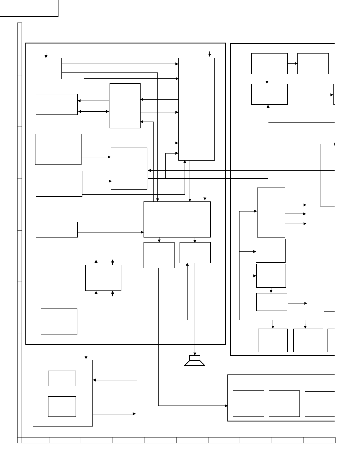
LC-20B6U-S
Y
C
D
BLOCK DIAGRAM
H
G
F
I2C
J3404
AV-IN1
IN2
J3401
J3402
J3408
J3407
J3406
TV-V
SIF
TUNER
TU3401
AV-IN2/OUT
COMPONENT-
COMPONENT-IN1
V2-OUT
L2, R2-IN/OUT
V1, S-Y/C, L1, R1, S-SW
Y2, PB2, PR2
Y1, PB1, PR1
DL1, DR1
E
PC-AUDIO-IN
J3409
L,R
ANALOG UNIT
AV2
IN/OUT
SWITCH
IC3404
Q3413
Q3410
Q3414
L, R-OUT
COMPONENT
SELECT
IC3403
V2-IN
V2-OUT
L2, R2-IN
Y
AUDIO
DECODER
(MSP)
IC3201
I2C
AV
SELECT
IC3401
L, R
2
I
C
PC-RGB IN
SC401
RGB/YPBPR
SWITCH
IC403
(720p, 1080i)
DC/DC
T701
IC701
Q716
V/DY/SY, SC
-12V
9V
35V
EDID
E2PROM
IC401
V/D
3.3V
HEAD
D
32V
(TU3401)
REG
IC3701
Q3710
Q3709
35V 9V
8V
(IC3201)
PHONE
AMPLIFIRE
IC3305
SOUND.VCC
AUDIO
AMPLIFIER
IC3304
DC/DC
IC703
Q712
2.5V
DC/DC
IC704
Q714
REG
IC1705
1.5V
I
C
SIG.VCC
OFL1, OSC
(CONTROLLER)
L_ERR
(MICON)
SP-L/R
17V
DC/DC
IC705
Q715
IREM, LED_POW, TIMER_LED, OPC_LED, OPC, HP
TSENCS
1.2V
DC/DC
IC707
Q721
R/C, LED U
OPC
SENSOR
IC4201
TEMP.
SENSOR
IC4001
HEAD
PHONE
JACK
J4021
B
A
DC IN
J3701
(DC12V)
INVERTER UNIT
LAMP
DRIVE
LAMP
ERROR
CHECK
INV.VCC
50
87109654321
Page 51

EDID
E2PROM
IC401
I2C
A-D
CONVERTER
IC8701
(480i, 480p)
I2C
VIDEO
PROCESSER
IC801
(VIDEODECODE)
(3D Y/C)
(I/P)
OFL1, OSC
MAIN UNIT
MEMORY
IC1202
IC1203
LCD
CONTROLLER
IC1201
3WIRE
LC-20B6U-S
LCD
PANEL
/SY, SC
V/DY/SY
REG
IC1704
VIDEO
AMP
IC803
DAC
IC802
SYNC
SEPARATE.
Q8802
IC8803
V/SY, SC
I2C
VSH3.3V
REG.
IC2004
OSD-R, G,B, BLK, I
BUFFER
Q8801
CVIN
CSYNC
L_ERR
REG.
IC2002
3.3V
5V
OSD-CK, VD, HD ,
MPU
IC2001
I2C
3WIRE
E2PROM
IC2005
RESET
IC2003
FPGA
CONFIGURATION
ROM
IC1204
3WIRE
GRADUATION
IC1101
CS-DRIVE
Q1101
Q1102
1.2V
C/DC
IC707
Q721
LED, OPC, HPDET, TSENDA, TSENCK,
5V
DC/DC
IC702
Q713
R/C, LED UNIT
HEAD
PHONE
JACK
J4021
LED
D4001
D4002
R/C
RECEIVER
RMC4001
KEY1, KEY2, POW2
CONTROL
POWER
SWITCH
S4053
SW4050-4052
SW4054-4056
OPERATION UNIT
51
KEYS
1716 1918151413121110
Page 52

LC-20B6U-S
OVERALL WIRING DIAGRAM
H
G
F
E
D
C
B
A
87109654321
52
Page 53

LC-20B6U-S
53
1716 1918151413121110
Page 54

LC-20B6U-S
DESCRIPTION OF SCHEMATIC DIAGRAM
VOL T AGE MEASUREMENT CONDITION:
1. The voltages at test points are measured on
exclusive AC adaptor and the stable supply voltage
of AC 120V. Signals are fed by a color bar signal
generator for servicing purpose and the above
voltages are measured with a 20k ohm/V tester.
INDICA TION OF RESIST OR & CAPACITOR:
RESISTOR
1. The unit of resistance “Ω” is omitted.
(K=kΩ=1000 Ω, M=MΩ).
2. All resistors are ± 5%, unless otherwise noted.
(J= ± 5%, F= ± 1%, D= ± 0.5%)
3. All resistors are 1/16W, unless otherwise noted.
4. All resistors are Carbon type, unless otherwise
noted.
C : Solid
S : Oxide Film T : Special
N : Metal Coating
CAPACITOR
1. All capacitors are µF, unless otherwise noted.
(P=pF=µµF).
2. All capacitors are 50V, unless otherwise noted.
3. All capacitors are Ceramic type, unless otherwise
noted.
(ML): Mylar (TA): Tantalum
(PF): Polypro Film (ST): Styrol
W
: Cement
CAUTION:
This circuit diagram is original one, therefore there may be a
slight difference from yours.
IMPORTANT SAFETY NOTICE:
P ARTS MARKED WITH “å” ( ) ARE
IMPORTANT FOR MAINTAINING THE SAFETY OF
THE SET. BE SURE TO REPLACE THESE PARTS
WITH SPECIFIED ONES FOR MAINTAINING THE
SAFETY AND PERFORMANCE OF THE SET.
AVIS DE SECURITE IMPORTANT:
LES PIECES MARQUEES “å” ( )SONT
IMPORTANTES POUR MAINTENIR LA SECURITE
DE L'APP AREIL.
NE REMPLACER CES PIEDES QUE PAR DES
PIECES DONT LE NUMERO EST SPECIFIE POUR
MAINTENIR LA SECURITE ET PROTEGER LE BON
FONCTIONNEMENT DE L'APPAREIL.
54
Page 55

SCHEMATIC DIAGRAM
Ë
OPERATION Unit
H
G
F
LC-20B6U-S
E
D
C
B
A
654321
55
Page 56

LC-20B6U-S
Ë
MAIN Unit-1/9
H
G
F
E
D
C
B
A
87109654321
56
Page 57

LC-20B6U-S
57
1716 1918151413121110
Page 58

LC-20B6U-S
Ë
MAIN Unit-2/9
H
G
F
E
D
C
B
A
87109654321
58
Page 59

LC-20B6U-S
59
1716 1918151413121110
Page 60

LC-20B6U-S
Ë
MAIN Unit-3/9
H
G
F
E
D
C
B
A
87109654321
60
Page 61

LC-20B6U-S
61
1716 1918151413121110
Page 62

LC-20B6U-S
Ë
MAIN Unit-4/9
H
G
F
E
D
C
B
A
87109654321
62
Page 63

LC-20B6U-S
63
1716 1918151413121110
Page 64

LC-20B6U-S
Ë
MAIN Unit-5/9
H
G
F
E
D
C
B
A
87109654321
64
Page 65

LC-20B6U-S
65
1716 1918151413121110
Page 66

LC-20B6U-S
Ë
MAIN Unit-6/9
H
G
F
E
D
C
B
A
87109654321
66
Page 67

LC-20B6U-S
67
1716 1918151413121110
Page 68

LC-20B6U-S
Ë
MAIN Unit-7/9
H
G
F
E
D
C
B
A
87109654321
68
Page 69

LC-20B6U-S
69
1716 1918151413121110
Page 70

LC-20B6U-S
Ë
MAIN Unit-8/9
H
G
F
E
D
C
B
A
87109654321
70
Page 71

LC-20B6U-S
71
1716 1918151413121110
Page 72

LC-20B6U-S
Ë
MAIN Unit-9/9
H
G
F
E
D
C
B
A
87109654321
72
Page 73

LC-20B6U-S
73
1716 1918151413121110
Page 74

LC-20B6U-S
Ë
ANALOG Unit-1/3
H
G
F
E
D
C
B
A
87109654321
74
Page 75

LC-20B6U-S
75
1716 1918151413121110
Page 76

LC-20B6U-S
Ë
ANALOG Unit-2/3
H
G
F
E
D
C
B
A
87109654321
76
Page 77

LC-20B6U-S
77
1716 1918151413121110
Page 78

LC-20B6U-S
Ë
ANALOG Unit-3/3
H
G
F
E
D
C
B
A
87109654321
78
Page 79

LC-20B6U-S
79
1716 1918151413121110
Page 80

LC-20B6U-S
Ë
R/C, LED Unit
H
G
F
E
D
C
B
A
654321
80
Page 81

PRINTED WIRING BOARD ASSEMBLIES
C4002
R4007
IC4001
P4001
C4203
IC4201
C4201
C4202
R4006
C4001
RMC4001
SLD4001
D4005
R4001
D4004
R4002
Q4001
D4001
Q4004
D4003
R4004
R4005
D4006
D4002
Q4003
J4021
H
LC-20B6U-S
G
OPERATION Unit (Side-A)
(QPWBXC541WJN1)
F
P4050
S4053
D4050 D4052
E
D4051
R4051
SW4052
R4052
SW4054
SW4051
R4050
OPERATION Unit (Chip Parts Side-A)
SW4050
R4053
SW4055
SW4056
(QPWBXC541WJN1)
D
C
A
B
R/C, LED Unit (Side-A)
(QPWBXC542WJN1)
R/C, LED Unit (Chip Parts Side-A)
(QPWBXC542WJN1)
81
654321
Page 82

LC-20B6U-S
H
G
F
E
D
C
B
A
MAIN Unit (Side-A)
654321
82
Page 83

LC-20B6U-S
SC401
TP2004
R1250
FB404
FB401
R467
R401
D401
R402
D402
R403
D403
D406
R466
R1251
C1253
C1252
D408 R462 D409 D410
D405 D404
R463 R464
R408
R407
C401
C1254
R409
C402
L401
C1267
P2004
D407
C1260
C1259
C407
C406
FB8703
TP2001
FB8702
C8718
C8717
C8716
C8719
FB8701
C8710 C8715
R8717
R8714
R8712
C8722
R8703
R8713
L804
C8708
C8721
C8702
C8709
R8702
C896
C8706
R8715 C8707
R8701
C8701
R8809
R8808
C8803
C8802 R8802
R8806
C8801
C8812
C8819
IC8803
C8807
R828
R8812
C8821
R8817
R8810
R8807
Q8802
C8820
L8801
C8822
C856
Q8801
R8805
R8814
R8803
R8801
C8804
R2074
TL2108
R8815
R2064
R2065
R2137
R2079
R2114
R2134
R2135
R2075
R2062
R2087 R2076
Q2007
R2133
R2061
R2129
R2070
Q2014
R2103
R2077
R2057
C2002
Q2013
R2141
R2110
FL2001
C2005
C2015
IC2001
SC2001
R2142
R2004
R2112
R2051
D2004
R2052
X2001
R2132
C2025
R2046
C2013
R2003
R2140 R2130
R2045
R2017
C2027
C2026
R2128
R2040
R2041
C2007
R2111
R2143
R2016
R2022
D703
C1704
C1709
IC704
Q703
L704
C733
Q710
IC705
C1705
Q708
SC701
C746
D704
L702
C734
Q713
D702
FB703
C743
Q706
L703
C741
C744
C735
C742
C771
C765
L701
R741
C723
T701
R760
C729
R714
R713
L706
C702
R727
C717
R742
R722
C715
TP2005
R701
R707
C710 R751
C751 C747
TP2068
Q702
D710
IC701
Q721
Q719
FB710
L705
Q717
IC707
C764
R1709 R1708
Q1704
D1706
R1710
Q1703
R1706
C1703
C1716
R1707
IC702
IC1703
R1703
R1717
C1701
R1718
R1724
C1719
R1719
R1723
Q1701
C1707
R1702
IC1704
C1702
C1708
R1704
L1702
C1706
Q1705
D1703
Q1702
D1704
C1715
R1714
C1714
D1702
R1701
C883
D1701
R1731
C1720
Q1707
R2015 R1730
D2003
C2001
C2004
D1705
Q1709
R2007
IC2004 IC1706
R2124
R1733
R2125
C2028
D2002
R1735
C1128
R2126
L810
L809
C1722
C1723
R1734
C2003
IC2002
Q1102
R1118
R2012
C1106
C1105
C1132
X801
C862
C864
R1119
Q1108
C860
C897
C861
R844
R842
L806
C1103
R820 R821
TL831
C1104
R827 R843
C1101
IC1101
C1102
R1101
R824
C833
C839
C837
C836
C824
C819
IC801
C818
C817
L805
C814
TL801
C816
R807
R806
L803
TL803
TL802
C895
C899
R1248 R1249
TL1221
TL1227
TL1240
TL1225
TL1223
R1262
R1244
TL1241
C1258
C1257
C1233
C1234
R1242
TL1226
C1221
C1222
R1241
C1232
IC1202
C1205 C1206
R1240
C1204 C1228
R1239
C1203 C1227
C1202 C1201
R1238
C1231
R1237
C1220
C1219
C1249
C1251
C1250
C1256
R1236
C1230
C1229
R1247 R1246
C1241
R1204
D1202
Q1210
R1215
R1220
R1224
R1225
R1217
R1222
P1202
Q1209
TP2006
C1274
IC1205
R1219
R1221
C1275
R1223
SC1201
TP2069
P2003
H
G
F
E
D
C
B
A
MAIN Unit (Chip Parts Side-A)
83
654321
Page 84
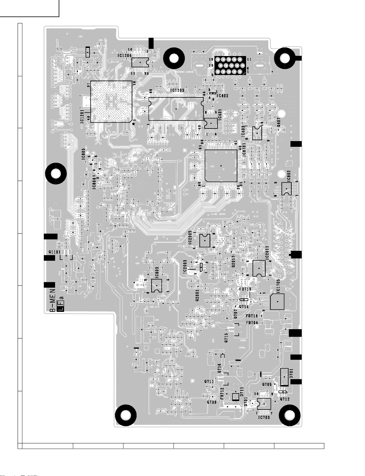
LC-20B6U-S
H
G
F
E
D
C
B
A
MAIN Unit (Side-B)
654321
84
Page 85

LC-20B6U-S
R763
R758
C728
C768
C767
C766
R777
R778
IC703
R721
C706
C732
Q701
C726
R743
Q709
R764
R765
FB712
Q712
D711
R735
R769
Q711
C736
Q705
C762
C738
R770
R776
Q716
D701
C749
D708
R789
D705
C750
TL716
C758
C739
C761
R771
D707
FB708
C727
TL717
R772
TL714
C756
C709
FB706
TL718
R740
TL715
TL702
R737
TL704
TL706
R746
C724
R762
C731
FB702
R775
TL713
Q715
C737
R724
TL701
R717
C704
R709
R766
C708
TL705
FB704
R767
FB701
TL708
TL711
R768
R747
R754
C719
R730
R718
C745
TL712
TL709
FB714
TL710
C730
R761
R744
C725
R736
C712
R702
C1712
Q707
TL1701
FB713
C707
R723
R715
C703
R708
Q714
R773
R774
C740
IC1705
R1720
TL1702
R745
R753
C718
R729
R716
C1710
TL2105
C711
C2030
R2023
R2011
R2032
Q2001
R2028
R2009
R2138
R2001
R2115
C2022
C2023
TL2070
TL2071
R2104R2131
C2029
TL2066
C2009
R2026
R2038
TL2106
TL2062
R2144
C2010
TL2060
Q2004
TL2109
C2018R2044
TL2059
TL2058
R2127
R2123
IC2011
TL2057
TL2056
C2012IC2003
R2043
R2036
C2008
TL2055
TL2054
R2047
TL2053
TL2052
Q2006
C2011
R2039
TL2073
R2031
TL2051
TL2050
R2048
C2006
TL2049
TL2047
C2016
C2032
TL2074
TL2046
TL2045
R2055
D2006
R2042
R2030
C2020
TL2044
TL2043
R2108
Q2017
TL2042
TL2041
R2020
R2069
TL2040
TL2039
R2139
R2105
R2021
TL2038
TL2037
R2059
C2021
R2090
TL2036
R2063
R2109
TL2035
R2027
TL2034
R2120
R2058
IC2005
TL2033
R2136
TL2032
TL2031
R2107Q2018
R2060
TL2030
TL2029
Q2008
R2029
TL2028
TL2027
R2106
TL2026
TL2025
C2031C2017
TL2023
R2056
R2113
TL2021
Q2003
R2014
R2091R2067
TL2099
Q2002
TL2019
C2014
R2049
R2019
TL2018
R833R830
R834R831
C882C880
R832R829
TL2101
R8718R8719R8720R8721
C881
TL2100
R457R444R450
IC802
C8703
C413
C411
C412
C8704
R8722
C8705
R451R439R445
R452R440R446
IC8701
R8723
TL2111
Q406
Q404
Q405
C8720
R442R448
R454
R8707
R441R447
R453
R8706
R443R449
R456
R422R420
R459
TL2117
C8714
C8713
R8704
R8705
C8712
C8711
TL2078
TL2077
R1257R1256
TL2120
TL2094
IC403
R465
R461
TL2076
TL2095
C1266
C1265
C1264
Q407
TL2075
TL2096
R460
TL2068
TL2097
IC401
TL2069
TL2121
R458R421R423
TL2113
TL2119
TL2115
R433
R438
R428
R436R431R426
TL2114
TL2116
R437R432R427
TL2112
TL2118
TL2098
Q403Q402Q401
R435
R430
R425
R410
R434R429R424
C1255
C410
C409
C408
C405
IC402
C404
R1226
R1227
C403
C1273
C1271
R406R405R404
R417
R416
R414
R415
R418
R419
FL403
FL402
FL401
TL2122
FB403FB402
TL401
TL402
TL403
TL409
TL2124
TL2125
TL404
R412
TL410
TL2123
TL405
TL406
TL407
TL408
R469
R468
R411
R1264
TL1249
TL1248
TL1246
TL1244
TL1242
R1210
TL1250
TL1251
R1218R1205
TL1247
TL1245
TL1243
D1201
TL1252
TL1253
R1216
C1242
R1206
TL1254
TL1256
C1243
Q1208Q1206R1213
TL1257
TL1258
TL1228
IC1204
C1244
TL1259
TL1260
Q1207
TL1229
TL1234
C1248
R1211
R1212
C1246
TL1231
C1247
TL1230
TL1239
TL1232
TL1238
TL1237
R1214
R1243
R1263
R1245
TL1278
C1270
C1269
TL1280
TL1281
TL1282
C1236
TL1283
TL1284
TL1285
R1255
TL1235
TL1286
IC1201
C1235
TL1295
TL1236
IC1203
TL1296
TL1297
TL1298
R1254
TL1299
TL1300
TL1301
TL1302
TL1303
TL1304
TL1222
TL1307
TL1224
C1263
C1262
C1261
C1268
TL1313
R1201
TL1314
R1202
R1203
R1208
R1253R1252
TL804
TL1315
TL1316
TL1317
TL1219
TL1220
TL1318
TL1319
TL805
TL1217
TL1218
TL1320
TL1321
R801
TL1322
R802
TL822
TL817
TL812
TL813
TL823
TL821
TL814
C803
TL820
TL809
TL810
TL824
IC805
C805
TL816
TL830
TL825
C802
C863
TL819
TL808
TL815
TL828
TL829
C804
C807
TL807
TL806
TL811
TL818
C8001
TL827
TL826
C801
R825
C834
C806
C808
R805
C810
C811
C879
C894
C828
R847
IC804
C878
C813R840
C809
R804
C812
C877
TL2104
C820C822
R841
C893
C825
C821
C815
C830
C823
R808
R809
TL2102
R826
C876C875
C1127
C827
C874
C1126
C826
C831
R1110
C1125
C832
C873R822C838
C829
R810
R811
C1124
C870R823C842
C868
C867
C866
C843C835
C1123
R839
R1109
C845
C1122
C846
TL2103
C865
C859
C869
C850
C872
C871
C1121
C851
C1120
R1108
C844
C857
C852
C855
C854
C1119
C1117
R812C1118
C1116
R1107
R816
C848
R817
C840
C841
C1115
R815
R814
C847
C1114
C1107
Q803
R1106
C1108
C849
C1113
R1104
C1112
C853
R1103R1105
C1111
TL832
R818
Q1107
Q801
R1102C1109
C1110
C858
R1117
R1116
R819R813
R837R838
R849
C888C892
Q1101
R848
R850
C1713
C887C886C890C891
C898
Q1105
C1130
C1131
R835R836
L1701
R1114
R1113
C889
C885
R1115
Q1103D1103
Q802
C1129
R1111
R846
IC803
R845
Q1106
R1112
Q1104
C884
R704
Q723
Q724
R797
R796
R795
Q722
R705
D720
R706
R1736
R1722
R1721
Q1706
C713
D1709
C1718
R1729
R1715
C1717
R748
C720
R731
R720
R719
C705
R710
R725
R759
R739
C722
R734
D1708
R1713
C752
R1711
R1712
C755
R786
R783
C1711
D1707
R728
R790
C770
R781
R782
C748
R784
R779
R792
R788
C757
R787
C769
C763
C714
R794
R793
C716
R732
R712
R726
R711
C701
R703
R738
C721
R733
TL2013
TL2014
R2002
TL2015
TL2016
TL2017
TL2107
TL1312
TL1311
TL1310
TL1309
TL1308
TL1306
TL1305
TL1294
TL1293
TL1292
TL1291
TL1290
TL1289
TL1288
TL1287
TL1279
TL1277
TL1276
TL1275
TL1274
TL1273
TL1272
TL1271
TL1270
TL1269
TL1268
TL1267
TL1266
TL1265
TL1264
TL1263
TL1262
TL1261
TL1255
R1209
H
G
F
E
D
C
B
A
MAIN Unit (Chip Parts Side-B)
85
654321
Page 86

LC-20B6U-S
H
G
F
ANALOG Unit (Side-A)
E
D
C
B
A
87109654321
86
Page 87

LC-20B6U-S
87
1716 1918151413121110
Page 88

LC-20B6U-S
H
G
F
ANALOG Unit (Chip Parts Side-A)
TP3432
D3707
C3424
C3231 C3229
D3704
C3268 C3267
Q3705 C3224
C3264
R3710
R3248
C3223
C3205
R3243
IC3209
R3468
R3212
C3227
C3715
C3710
C3265
IC3202
X3203
X3202
R3266
R3207
R3242
C3702
R3732
IC3404
R3241
D3702
J3409
E
D
C
J3407 J3404
B
J3406
A
C3408
R3402
C3407
R3403
R3440
FB3402
R3415
R3412
R3421
R3416
C3405
R3413
C3406
R3409
D3401
D3402
R3423
R3406
R3428
R3422
R3420
R3414
D3405
C3418
Q3401
Q3402
C3417
C3413
R3424
R3401
R3438
R3439
D3406
C3425
R3709
Q3403
C3414
TP3434
C3714
Q3706
D3705
R3703
R3444
D3407
R3443
R3469
C3225
C3701
R3501
C3459
R3214
R3206
C3207
R3265
R3208
C3239
R3221
Q3204
R3210
R3209
C3226
R3215
C3204
L3202
C3221
R3239
R3236
R3235
R3234
D3703
R3503
C3266
C3263
R3263
R3261
R3203
C3704
C3203
R3482
Q3413
R3701
Q3203
R3491
C3209
R3201
R3216
Q3201
R3204
R3371
R3202
C3206
R3219
R3702
R3220
C3211
C3465
Q3410
R3213
IC3204
R3218
C3333
Q3405
C3202
R3217
X3201
R3476
IC3205
P3701
Q3417
C3431
C3222
C3208
C3219
C3220
R3505
FB3201
C3213 R3211 C3212
R3504 R3515
C3432
C3336
R3462
L3201
C3476
C3469
R3324
C3330 Q3301
R3514
Q3415
C3218
R3322
C3214
R3459
C3427
C3334
Q3414
R3509
IC3206
C3429
R3222
C3216
C3338
R3228
C3335
C3434
R3325
R3229
Q3302
R3517
R3451
R3230
R3323
C3331
R3483
C3230
R3231
L3402
R3332
IC3304
C3479
R3463
R3464
C3228
IC3201
L3203
Q3303
R3407
R3237
C3232
C3235
C3236
C3233
P3302
C3449
C3450
Q3406
L3303
C3332
C3340
C3358
IC3401
R3470
C3234
C3237
C3238
C3337
R3330
R3411
C3215
R3328
C3447
C3409
C3245
R3250
R3329
R3225
C3347
Q3404
R3226
R3331
D3205
C3410
D3204
R3257
C3217
D3202
R3205
R3418 R3404
C3364
Q3207
R3255
C3243
R3453
R3452
R3344
R3343
C3361
C3346
C3349
C3359
R3474
C3438
C3440
R3455
C3439
R3454
C3428
C3244
C3261
C3262
R3256
C3430
C3306
C3308
C3309
C3365
D3206
IC3305
R3345
D3208 D3207
R3301
C3350
R3346
R3370
C3301
R3302
C3302
C3348
C3252
C3253
C3254
R3359
R3339
C3251
R3357
C3362
C3345
SC3403
IC3301
R3358
Q3715
R3342
D3304
R3341
C3344
R3340
R3471
C3343
R3477
R3472
C3305
C3339
C3442
R3460
C3437
C3436
R3465
C3445
R3457
C3363
R3461
C3312
R3306
R3369
C3304
R3303
C3303
C3433
C3444
C3435
D3201
FB3203
P3303
R3496
R3308
R3304 R3305
C3307
C3446
C3443
C3311
R3307
IC3203
R3499
IC3403
C3310
C3210
C3201
C3416
R3493
R3492
IC3402
FB3411
C3441
R3419
FB3410
R3498
R3490
R3497
R3489
R3466
C3452
FB3409
C3448
D3420
P3404
88
87109654321
Page 89

LC-20B6U-S
C3443
P3704
Q3709
Q3710
C3707 C3708
R3722
C3711
R3727
R3726
R3723
R3725
R3728
IC3701
R3729
C3713
R3718
C3712
C3709
R3730
D3706
TP3433
R3441
L3401
C3419
C3422
C3426
D3404
D3403
C3423
R3427
R3410
R3405
C3402
R3431
R3408
R3417
R3434
R3425
R3435
R3430
R3436
C3421
R3429
C3420
R3426
P3702
J3402 J3408
J3401
C3446
R3499
C3311
R3307
IC3203
IC3403
C3310
C3210
C3201
C3416
R3493
R3492
IC3402
FB3411
C3441
R3419
FB3410
R3498
R3490
R3497
R3489
R3466
C3452
FB3409
D3420
P3404
C3448
Q3701
D3708
Q3702
D3709
R3704
C3474
R3530
R3532
R3519
R3529
Q3419
P3703
Q3409
Q3408
F3702
Q3407
C3470
C3472
D3701
R3432
F3701
R3495
R3494
C3401
C3403
C3471
TU3401
R3447
C3467
C3473
L3405
C3464
C3462
TP3431
C3458
R3524
R3533
Q3418
R3531
R3736
R3518
J3701
89
1716 1918151413121110
Page 90

LC-20B6U-S
Ref. No. Part No. ★ Description Code Ref. No. Part No. ★ Description Code
P ARTS LIST
LISTE DES PIECES
P ARTS REPLACEMENT
Replacement parts which have these special safety characteristics identified in this manual ; electrical components having such features are
identified by å and shaded areas in the Replacement Parts Lists and
Schematic Diagrams. The use of a substitute replacement part which
does no have the same safety characteristic as the factory recommended
replacement parts shown in this service manual may create shock, fire
or other hazards.
"HOW TO ORDER REPLACEMENT P ARTS"
To have your order filled promptly and correctly, please furnish the following informations.
1. MODEL NUMBER 2. REF. NO.
3. PAR T NO. 4. DESCRIPTION
in USA: Contact your nearest SHARP Parts Distributor to order. For
location of SHARP Parts Distributor, Please call Toll-Free;
1-800-BE-SHARP
★ MARK: SP ARE PARTS-DELIVERY SECTION
Ref. No. Part No. ★ Description Code Ref. No. Part No. ★ Description Code
Les pi`eces de rechange qui pr élelesentent ces caract éleristiques sp
éleciales de s élecurit éle, sont identifi élees dans ce manuel : les pi`eces
élelectriques qui pr élesentent ces particularit éles, sont rep éler élee
par la marque å et sont hachur élees dans les listes de pi`eces et dans
les diagrammes sch élematiques.
La substitution d'une pi`ece de rechange par une autre qui ne pr éLesente
pas les m éoemes caract éLeristiques de s élecurit éle que la pi`ece
recommand élee parl'usine et dans ce manuel de service, peut provoquer
une éLelectrocution, un incendie ou toutautre sinistre.
"COMMENT COMMANDER LES PIECES DE RECHANGE"
Pour que votre commande soit rapidement et correctement remplie,
veuillez fournir les renseignements suivants.
1. NUMERO DU MODELE 2. NO. DE REF
3. NO. DE PIECE 4. DESCRIPTION
in CANADA: Contact SHARP Electronics of Canada Limited
★ MARQUE: SECTION LIVRAISON DES PIECES DERECHANGE
PRINTED WIRING BOARD ASSEMBLYS
(NOT REPLACEMENT ITEM)
DUNTKC539FE06 – MAIN Unit —
DUNTKC540DE03 – ANALOG Unit —
DUNTKC541DE03 – OPERATION Unit —
DUNTKC542DE03 – R/C, LED Unit —
RUNTKA087WJZZ J INVERTER Unit BP
DUNTKC539FE06 – MAIN Unit —
DUNTKC540DE06 – ANALOG Unit —
DUNTKC541DE06 – OPERATION Unit —
DUNTKC542DE06 – R/C, LED Unit —
RUNTKA087WJZZ J INVERTER Unit BP
NOTE: THE PARTS HERES SHOWN ARE SUPPLIED AS AN
ASSEMBLY BUT NOT INDEPENDENTLY.
RLCDTA031WJZZ J 20" LCD Panel Unit DC
U.S.A/CANADA
KOREA
LCD P ANEL
IC401 VHiBR24C21F-1Y J BR24C21F-E2 AG
IC402 VHiNC7WZ14P-1Y J NC7WZ14P6X AD
IC403 VHiFSAV330T-1Y J FSAV330MTCX AN
IC701 RH-iXA828WJZZY J BD9300FV-FE2 AH
IC702 RH-iXA828WJZZY J BD9300FV-FE2 AH
IC703 RH-iXA828WJZZY J BD9300FV-FE2 AH
IC704 RH-iXA828WJZZY J BD9300FV-FE2 AH
IC705 RH-iXA828WJZZY J BD9300FV-FE2 AH
IC707 RH-iXA828WJZZY J BD9300FV-FE2 AH
IC801 VHiTC90203X-1Q J I.C. BM
IC802 VHiM62332FP-1Y J M62332FP AL
IC803 VHiBA7655AF-1Y J BA7655AF AG
IC804 VHiTC7PA53U-1Y J TC7PA53FU AB
IC1101 VHiBD8132FV-1Y J I.C. AX
IC1201 RH-iXA990WJZZQ J I.C. BH
IC1202 RH-iXA312WJN1Q J MT48LC2M32B2TG AX
IC1203 RH-iXA312WJN1Q J MT48LC2M32B2TG AX
IC1204 RH-iXA991WJN2Y J I.C. AS
IC1703 VHiNJM2147M-1Y J NJM2147M-TE1 AF
IC1704 VHiMM1563DF-1Y J MM1563DFBE AE
IC1705 VHiPQ015EZ1-1Y J PQ015EZ01ZP AG
IC1706 VHiLM1117MJ-1Y J LM1117MPX-ADJ AF
IC2001 RH-iXA625WJN1Q J M306V7FHFP BK
IC2002 VHiPQ1L333M-1Y J PQ1L333M2SP AD
IC2003 VHiBD4729G+-1Y J BD4729G-TR AD
IC2004 VHiSi3010KM-1Y J SI-3010KM-Tl AF
IC2005 VHiBR24L32F-1Y J I.C. AG
IC2011 VHiMB3771PF-1Y J MB3771PF-G-BND AG
IC8701 VHiAD9883A1-1Q J AD9883AKST-110 BD
IC8803 VHiBA7046F/-1Y J BA7046F AF
CHANGE DES PIECES
Phone (416) 890-2100
DUNTKC539FE06
MAIN Unit
INTEGRA TED CIRCUITS
Q401 VS2SC5384C/-1Y J 2SC5384C AB
Q402 VS2SC5384C/-1Y J 2SC5384C AB
Q403 VS2SC5384C/-1Y J 2SC5384C AB
Q404 VS2SC5384C/-1Y J 2SC5384C AB
Q405 VS2SC5384C/-1Y J 2SC5384C AB
Q406 VS2SC5384C/-1Y J 2SC5384C AB
Q705 VSUML2N++++-1Y J UML2N AC
Q706 VSUML2N++++-1Y J UML2N AC
Q707 VSUML2N++++-1Y J UML2N AC
Q708 VSUML2N++++-1Y J UML2N AC
90
TRANSISTORS
Page 91

LC-20B6U-S
Ref. No. Part No. ★ Description Code Ref. No. Part No. ★ Description Code
DUNTKC539FE06
MAIN Unit (Continued)
Q709 VSUML1N++++-1Y J UML1N AC
Q710 VSUML1N++++-1Y J UML1N AC
Q711 VSUML2N++++-1Y J UML2N AC
Q712 VSRTQ035P02-1Y J RTQ035P02 AD
Q713 VSRTQ035P02-1Y J RTQ035P02 AD
Q714 VSRTQ035P02-1Y J RTQ035P02 AD
Q715 VSRHP020N06-1Y J RHP020N06 AD
Q716 VSRHP020N06-1Y J RHP020N06 AD
Q719 VSUML2N++++-1Y J UML2N AC
Q721 VSRTQ035P02-1Y J RTQ035P02 AD
Q801 VS2SC3928AR-1Y J 2SC3928AR AB
Q802 VS2SA1037KQ-1Y J 2SA1037KQ AA
Q803 VS2SA1037KQ-1Y J 2SA1037KQ AA
Q1101 VS2SC4520//-1Y J 2SC4520 AE
Q1102 VS2SA1729//-1Y J 2SA1729 AF
Q1103 VSFMMT718//-1Y J FMMT718 AE
Q1104 VSDTC144EE/-1Y J DTC144EE AA
Q1105 VS2SA1037KQ-1Y J 2SA1037KQ AA
Q1106 VSDTC114EE/-1Y J DTC114EE AB
Q1107 VS2SA1037KQ-1Y J 2SA1037KQ AA
Q1108 VSDTC114EE/-1Y J DTC114EE AB
Q1701 VS2SA1037KQ-1Y J 2SA1037KQ AA
Q1702 VSDTC144EE/-1Y J DTC144EE AA
Q1703 VS2SA1036K/-1Y J 2SA1036K AC
Q1705 VSDTC144EE/-1Y J DTC144EE AA
Q1706 VS2SC3928AR-1Y J 2SC3928AR AB
Q1707 VSFMMT718//-1Y J FMMT718 AE
Q1709 VSDTC144EE/-1Y J DTC144EE AA
Q2002 VS2SA1037KQ-1Y J 2SA1037KQ AA
Q2003 VSDTC144EE/-1Y J DTC144EE AA
Q2004 VS3LN01S///-1Y J 3LN01S AC
Q2006 VSDTC114EE/-1Y J DTC114EE AB
Q2007 VSUPA606T//-1Y J UPA606T AD
Q2008 VSDTC144EE/-1Y J DTC144EE AA
Q2013 VSDTC144EE/-1Y J DTC144EE AA
Q2014 VSDTA144EE/-1Y J DTA144EE AA
Q8801 VS2SA1989R/-1Y J 2SA1989R AB
Q8802 VS2SC5384C/-1Y J 2SC5384C AB
DIODES
D404 VHDDAN217U+-1Y J Diode AB
D405 VHDDAN217U+-1Y J Diode AB
D406 VHD1SS250//1EY J Diode AB
D407 VHD1SS250//1EY J Diode AB
D701 VHDRB051L40-1Y J Diode AD
D702 VHDRB051L40-1Y J Diode AD
D703 VHDRB051L40-1Y J Diode AD
D704 VHDRB051L40-1Y J Diode AD
D705 VHDRF071M2S-1Y J Diode AD
D707 VHD1SS355//-1Y J Diode AB
D708 VHDRB160M40-1Y J Diode AC
D710 VHDRB051L40-1Y J Diode AD
D711 VHDSFPB56//2EY J Diode AC
D720 VHDDAN222//-1Y J Diode AA
D1103 VHD1SS250//1EY J Diode AB
D1701 VHDDAN222//-1Y J Diode AA
D1702 RH-EX1224CEZZY J Zener Diode, 2V AB
D1703 VHDDAN222//-1Y J Diode AA
D1704 RH-EX1224CEZZY J Zener Diode, 2V AB
D1705 VHDDAN202K/-1Y J Diode AB
D1706 VHDDAN222//-1Y J Diode AA
D1707 VHD1SS250//1EY J Diode AB
D1708 VHDRB481K++-1Y J Diode AD
D1709 VHDDAN222//-1Y J Diode AA
D2002 VHDRB491D++-1Y J Diode AD
D2003 VHDDAN202K/-1Y J Diode AB
P ACKAGED CIRCUITS
X801 RCRSCA083WJZZY J Crystal AG
X2001 RCRSC0032TAZZY J Crystal, 27MHz AG
FL401 RFiLN0003TAZZY J Filter AD
FIL TER AND COILS
FL402 RFiLN0003TAZZY J Filter AD
FL403 RFiLN0003TAZZY J Filter AD
FL2001 RFiLZA003WJPZY J Filter AD
L401 VPCNN220J2R9NY J Peaking 22µH AB
L701 RCiLPA232WJZZY J Coil AE
L702 RCiLPA232WJZZY J Coil AE
L703 RCiLPA232WJZZY J Coil AE
L704 RCiLPA232WJZZY J Coil AE
L705 RCiLPA232WJZZY J Coil AE
L706 RCiLPA148WJZZY J Coil AE
L805 RCiLPA143WJZZY J Coil AD
L809 VP-9N120KR46NY J Peaking 12µH AB
L810 VP-9N120KR46NY J Peaking 12µH AB
L1701 VPCKM1R2JR44NY J Peaking 1.2µH AB
L1702 VPCNN470J5R4NY J Peaking 47µH AB
L8801 VPD9M220J2R7NY J Peaking 22µH AC
TRANSFORMER
T701 RTRNWA141WJZZYJ Transformer AF
CAPACITORS
C401 RC-KZA041WJZZY J 10 10V Ceramic AC
C402 VCKYCY1EB103KY J 0.01 25V Ceramic AA
C403 VCCCCY1HH330JY J 33p 50V Ceramic AA
C404 VCCCCY1HH330JY J 33p 50V Ceramic AA
C405 VCKYCY1EF104ZY J 0.1 25V Ceramic AA
C406 VCKYTV1AB105KY J 1 10V Ceramic AC
C407 VCKYCY1EF104ZY J 0.1 25V Ceramic AA
C408 RC-KZA041WJZZY J 10 10V Ceramic AC
C409 RC-KZA041WJZZY J 10 10V Ceramic AC
C410 RC-KZA041WJZZY J 10 10V Ceramic AC
C411 RC-KZA041WJZZY J 10 10V Ceramic AC
C412 RC-KZA041WJZZY J 10 10V Ceramic AC
C413 RC-KZA041WJZZY J 10 10V Ceramic AC
C701 VCKYCY1EF104ZY J 0.1 25V Ceramic AA
C702 VCKYCY1EB333KY J 0.033 25V Ceramic AA
C703 VCKYCY1EB333KY J 0.033 25V Ceramic AA
C704 VCKYCY1EB333KY J 0.033 25V Ceramic AA
C705 VCKYCY1EB333KY J 0.033 25V Ceramic AA
C706 VCKYCY1EB333KY J 0.033 25V Ceramic AA
C708 VCKYCY1EF104ZY J 0.1 25V Ceramic AA
C710 VCCCCY1HH102JY J 1000p 50V Ceramic AB
C711 VCCCCY1HH102JY J 1000p 50V Ceramic AB
C712 VCCCCY1HH102JY J 1000p 50V Ceramic AB
C713 VCCCCY1HH331JY J 330p 50V Ceramic AA
C714 VCKYCY1HB332KY J 3300p 50V Ceramic AA
C716 VCCCCY1HH330JY J 33p 50V Ceramic AA
C721 VCCCCY1HH330JY J 33p 50V Ceramic AA
C722 VCCCCY1HH101JY J 100p 50V Ceramic AA
C723 VCCCCY1HH101JY J 100p 50V Ceramic AA
C724 VCCCCY1HH330JY J 33p 50V Ceramic AA
C725 VCCCCY1HH101JY J 100p 50V Ceramic AA
C726 VCCCCY1HH181JY J 180p 50V Ceramic AA
C727 VCKYCY1EB123KY J 0.012 25V Ceramic AA
C728 VCKYCY1EF104ZY J 0.1 25V Ceramic AA
C729 VCKYCY1EB123KY J 0.012 25V Ceramic AA
C730 VCKYCY1EB123KY J 0.012 25V Ceramic AA
C731 VCKYCY1EF104ZY J 0.1 25V Ceramic AA
C732 RC-KZA109WJZZY J 10 16V Ceramic AC
C733 RC-KZA109WJZZY J 10 16V Ceramic AC
C734 RC-KZA109WJZZY J 10 16V Ceramic AC
C735 RC-KZA109WJZZY J 10 16V Ceramic AC
C736 VCCCCY1HH102JY J 1000p 50V Ceramic AB
C737 VCKYCY1EB223KY J 0.022 25V Ceramic AA
C738 VCCCCY1HH102JY J 1000p 50V Ceramic AB
C739 VCCCCY1HH102JY J 1000p 50V Ceramic AB
C740 VCCCCY1HH102JY J 1000p 50V Ceramic AB
C741 RC-KZA108WJZZY J 10 10V Ceramic AC
C742 RC-KZA101WJZZY J 10 6.3V Ceramic AC
C743 RC-KZA108WJZZY J 10 10V Ceramic AC
C744 RC-KZA101WJZZY J 10 6.3V Ceramic AC
C745 RC-KZA108WJZZY J 10 10V Ceramic AC
C746 RC-KZA110WJZZY J 10 25V Ceramic AD
91
Page 92

LC-20B6U-S
Ref. No. Part No. ★ Description Code Ref. No. Part No. ★ Description Code
DUNTKC539FE06
MAIN Unit (Continued)
C747 VCEASX1CN106MY J 10 16V Electrolytic AC
C748 VCKYCY1EB333KY J 0.033 25V Ceramic AA
C750 RC-KZA215WJZZY J 1 50V Ceramic AA
C752 VCCCCY1HH102JY J 1000p 50V Ceramic AB
C756 RC-KZA109WJZZY J 10 16V Ceramic AC
C757 VCCCCY1HH101JY J 100p 50V Ceramic AA
C758 RC-KZA109WJZZY J 10 16V Ceramic AC
C761 RC-KZA109WJZZY J 10 16V Ceramic AC
C762 VCKYCY0JB105KY J 1 6.3V Ceramic AC
C763 VCCCCY1HH102JY J 1000p 50V Ceramic AB
C764 RC-KZA108WJZZY J 10 10V Ceramic AC
C765 RC-KZA109WJZZY J 10 16V Ceramic AC
C766 VCKYCY1HB562KY J 5600p 50V Ceramic AA
C771 VCEASY1CN337MY J 330 16V Electrolytic AD
C801 VCKYCY1HB103KY J 0.01 50V Ceramic AA
C802 VCKYCY1HB103KY J 0.01 50V Ceramic AA
C803 VCKYCY1HB103KY J 0.01 50V Ceramic AA
C804 VCKYCY1HB103KY J 0.01 50V Ceramic AA
C805 VCKYCY1HB103KY J 0.01 50V Ceramic AA
C806 VCKYCY1HB103KY J 0.01 50V Ceramic AA
C807 VCKYCY1HB103KY J 0.01 50V Ceramic AA
C808 VCKYCY1HB103KY J 0.01 50V Ceramic AA
C809 VCKYCY1HB103KY J 0.01 50V Ceramic AA
C810 VCKYCY1HB103KY J 0.01 50V Ceramic AA
C811 VCKYCY1HB103KY J 0.01 50V Ceramic AA
C812 VCKYCY1HB103KY J 0.01 50V Ceramic AA
C813 VCKYCY1EF104ZY J 0.1 25V Ceramic AA
C814 VCKYCY1HB152KY J 1500p 50V Ceramic AA
C815 VCKYCY1EF104ZY J 0.1 25V Ceramic AA
C816 VCKYCY1HB103KY J 0.01 50V Ceramic AA
C817 VCKYCY1HB103KY J 0.01 50V Ceramic AA
C818 VCKYCY1HB103KY J 0.01 50V Ceramic AA
C819 VCKYCY1HB103KY J 0.01 50V Ceramic AA
C820 VCKYCY1EF104ZY J 0.1 25V Ceramic AA
C821 VCKYCY1EF104ZY J 0.1 25V Ceramic AA
C823 VCKYCY1CB104KY J 0.1 16V Ceramic AB
C824 VCKYCY1HB103KY J 0.01 50V Ceramic AA
C825 VCKYCY1HB103KY J 0.01 50V Ceramic AA
C826 VCKYCY1EF104ZY J 0.1 25V Ceramic AA
C827 VCKYCY1HB103KY J 0.01 50V Ceramic AA
C829 VCKYCY1CB104KY J 0.1 16V Ceramic AB
C830 VCKYCY1HB103KY J 0.01 50V Ceramic AA
C831 VCKYCY1HB103KY J 0.01 50V Ceramic AA
C832 VCKYCY1EF104ZY J 0.1 25V Ceramic AA
C833 VCKYCY1HB103KY J 0.01 50V Ceramic AA
C834 VCKYCY1HB103KY J 0.01 50V Ceramic AA
C836 VCKYCY1HB103KY J 0.01 50V Ceramic AA
C837 VCKYCY1HB103KY J 0.01 50V Ceramic AA
C838 VCKYCY1HB103KY J 0.01 50V Ceramic AA
C839 VCKYCY1HB103KY J 0.01 50V Ceramic AA
C840 VCCCCY1HH680JY J 68p 50V Ceramic AA
C841 VCKYTV1CB105KY J 1 16V Ceramic AC
C842 VCKYCY1HB103KY J 0.01 50V Ceramic AA
C843 VCKYCY1EF104ZY J 0.1 25V Ceramic AA
C844 VCKYCY1EF104ZY J 0.1 25V Ceramic AA
C845 VCKYCY1HB103KY J 0.01 50V Ceramic AA
C846 VCCCCY1HH680JY J 68p 50V Ceramic AA
C847 VCCCCY1HH151JY J 150p 50V Ceramic AA
C848 VCCCCY1HH151JY J 150p 50V Ceramic AA
C849 VCKYTV1CB105KY J 1 16V Ceramic AC
C850 VCKYCY1HB103KY J 0.01 50V Ceramic AA
C851 VCKYCY1HB103KY J 0.01 50V Ceramic AA
C852 VCKYCY1HB103KY J 0.01 50V Ceramic AA
C853 VCCCCY1HH4R0CY J 4p 50V Ceramic AA
C854 VCKYCY1EF104ZY J 0.1 25V Ceramic AA
C855 VCKYCY1EF104ZY J 0.1 25V Ceramic AA
C856 VCAAPC0GJ336MY J 33 4V Electrolytic AE
C857 VCKYCY1HB152KY J 1500p 50V Ceramic AA
C858 VCKYCY1HB103KY J 0.01 50V Ceramic AA
C859 VCKYCY1EF104ZY J 0.1 25V Ceramic AA
C860 VCEASX1CN106MY J 10 16V Electrolytic AC
C861 VCKYCY1HB103KY J 0.01 50V Ceramic AA
C862 VCCCCY1HH6R0DY J 6p 50V Ceramic AA
C864 VCCCCY1HH6R0DY J 6p 50V Ceramic AA
C865 VCKYCY1HB103KY J 0.01 50V Ceramic AA
C866 VCKYCY1HB103KY J 0.01 50V Ceramic AA
C867 VCKYCY1HB103KY J 0.01 50V Ceramic AA
C868 VCKYCY1HB103KY J 0.01 50V Ceramic AA
C869 VCKYCY1HB103KY J 0.01 50V Ceramic AA
C870 VCKYCY1HB103KY J 0.01 50V Ceramic AA
C871 VCKYCY1HB103KY J 0.01 50V Ceramic AA
C872 VCKYCY1HB103KY J 0.01 50V Ceramic AA
C873 VCKYCY1HB103KY J 0.01 50V Ceramic AA
C874 VCKYCY1HB103KY J 0.01 50V Ceramic AA
C875 VCKYCY1HB103KY J 0.01 50V Ceramic AA
C876 VCKYCY1HB103KY J 0.01 50V Ceramic AA
C877 VCKYCY1HB103KY J 0.01 50V Ceramic AA
C878 VCKYCY1HB103KY J 0.01 50V Ceramic AA
C879 VCKYCY1HB103KY J 0.01 50V Ceramic AA
C880 VCKYCY1EF104ZY J 0.1 25V Ceramic AA
C881 VCKYCY1EF104ZY J 0.1 25V Ceramic AA
C882 VCKYCY1EF104ZY J 0.1 25V Ceramic AA
C883 VCEASX1CN106MY J 10 16V Electrolytic AC
C884 VCKYCY1EF104ZY J 0.1 25V Ceramic AA
C885 VCKYCY1CB104KY J 0.1 16V Ceramic AB
C886 VCCCCY1HH100DY J 10p 50V Ceramic AA
C887 VCCCCY1HH100DY J 10p 50V Ceramic AA
C888 VCCCCY1HH100DY J 10p 50V Ceramic AA
C889 RC-KZA041WJZZY J 10 10V Ceramic AC
C890 VCCCCY1HH100DY J 10p 50V Ceramic AA
C891 VCCCCY1HH100DY J 10p 50V Ceramic AA
C892 VCCCCY1HH100DY J 10p 50V Ceramic AA
C895 RC-KZA070WJZZY J 22 6.3V Ceramic AD
C896 RC-KZ0117TAZZY J 4.7 6.3V Ceramic AD
C897 RC-KZ0117TAZZY J 4.7 6.3V Ceramic AD
C899 VCAAPC0GJ336MY J 33 4V Electrolytic AE
C1101 RC-KZA101WJZZY J 10 6.3V Ceramic AC
C1102 VCKYCY1EF104ZY J 0.1 25V Ceramic AA
C1103 RC-KZA110WJZZY J 10 25V Ceramic AD
C1104 VCKYCY1EF104ZY J 0.1 25V Ceramic AA
C1105 RC-KZ0072TAZZY J 1 25V Ceramic AC
C1106 RC-KZ0072TAZZY J 1 25V Ceramic AC
C1107 VCKYCY1HB102KY J 1000p 50V Ceramic AA
C1108 VCKYCY1HB102KY J 1000p 50V Ceramic AA
C1109 VCKYCY1EF104ZY J 0.1 25V Ceramic AA
C1132 RC-KZA110WJZZY J 10 25V Ceramic AD
C1201 VCKYCY1HB103KY J 0.01 50V Ceramic AA
C1202 VCKYCY1HB103KY J 0.01 50V Ceramic AA
C1203 VCKYCY1HB103KY J 0.01 50V Ceramic AA
C1204 VCKYCY1HB103KY J 0.01 50V Ceramic AA
C1205 VCKYCY1HB103KY J 0.01 50V Ceramic AA
C1206 VCKYCY1HB103KY J 0.01 50V Ceramic AA
C1219 VCKYCY1HB103KY J 0.01 50V Ceramic AA
C1220 VCKYCY1HB103KY J 0.01 50V Ceramic AA
C1221 VCKYCY1HB103KY J 0.01 50V Ceramic AA
C1222 VCKYCY1HB103KY J 0.01 50V Ceramic AA
C1227 VCKYCY1HB103KY J 0.01 50V Ceramic AA
C1228 VCKYCY1HB103KY J 0.01 50V Ceramic AA
C1229 VCKYCY1HB103KY J 0.01 50V Ceramic AA
C1230 VCKYCY1HB103KY J 0.01 50V Ceramic AA
C1231 VCKYCY1HB103KY J 0.01 50V Ceramic AA
C1232 VCKYCY1HB103KY J 0.01 50V Ceramic AA
C1233 VCKYCY1HB103KY J 0.01 50V Ceramic AA
C1234 VCKYCY1HB103KY J 0.01 50V Ceramic AA
C1235 VCKYCY1HB103KY J 0.01 50V Ceramic AA
C1236 VCKYCY1HB103KY J 0.01 50V Ceramic AA
C1241 VCCCCY1HH5R0CY J 5p 50V Ceramic AA
C1242 RC-KZ1025CEZZY J 1 10V Ceramic AB
C1243 RC-KZ1025CEZZY J 1 10V Ceramic AB
C1244 RC-KZ1025CEZZY J 1 10V Ceramic AB
C1249 VCKYCY1HB103KY J 0.01 50V Ceramic AA
C1250 VCKYCY1HB103KY J 0.01 50V Ceramic AA
C1251 VCKYCY1HB103KY J 0.01 50V Ceramic AA
C1252 VCKYCY1HB103KY J 0.01 50V Ceramic AA
C1253 VCKYCY1HB103KY J 0.01 50V Ceramic AA
C1254 VCKYCY1HB103KY J 0.01 50V Ceramic AA
92
Page 93

LC-20B6U-S
Ref. No. Part No. ★ Description Code Ref. No. Part No. ★ Description Code
DUNTKC539FE06
MAIN Unit (Continued)
C1255 VCKYCY1HB103KY J 0.01 50V Ceramic AA
C1256 VCKYCY1HB103KY J 0.01 50V Ceramic AA
C1257 VCKYCY1HB103KY J 0.01 50V Ceramic AA
C1258 VCKYCY1HB103KY J 0.01 50V Ceramic AA
C1259 VCKYCY1HB103KY J 0.01 50V Ceramic AA
C1260 VCKYCY1HB103KY J 0.01 50V Ceramic AA
C1261 VCKYCY1HB103KY J 0.01 50V Ceramic AA
C1262 VCKYCY1HB103KY J 0.01 50V Ceramic AA
C1263 VCKYCY1HB103KY J 0.01 50V Ceramic AA
C1264 VCKYCY1HB103KY J 0.01 50V Ceramic AA
C1265 VCKYCY1HB103KY J 0.01 50V Ceramic AA
C1266 VCKYCY1HB103KY J 0.01 50V Ceramic AA
C1267 VCKYCY1HB103KY J 0.01 50V Ceramic AA
C1268 VCKYCY1HB103KY J 0.01 50V Ceramic AA
C1269 VCKYCY1HB103KY J 0.01 50V Ceramic AA
C1270 VCKYCY1HB103KY J 0.01 50V Ceramic AA
C1271 VCKYCY1HB103KY J 0.01 50V Ceramic AA
C1273 VCKYCY1HB103KY J 0.01 50V Ceramic AA
C1701 VCKYCY1EF104ZY J 0.1 25V Ceramic AA
C1703 VCKYCY1EF104ZY J 0.1 25V Ceramic AA
C1704 VCEASY1CN337MY J 330 16V Electrolytic AD
C1705 VCKYTV1CB105KY J 1 16V Ceramic AC
C1706 VCCCCY1HH471JY J 470p 50V Ceramic AA
C1707 RC-KZA070WJZZY J 22 6.3V Ceramic AD
C1708 VCKYTV1CB105KY J 1 16V Ceramic AC
C1709 VCEASX0JN226MY J 22 6.3V Electrolytic AB
C1710 VCKYTV1CB105KY J 1 16V Ceramic AC
C1711 RC-KZA041WJZZY J 10 10V Ceramic AC
C1712 VCKYCY1EF104ZY J 0.1 25V Ceramic AA
C1713 RC-KZA110WJZZY J 10 25V Ceramic AD
C1714 VCEASX1HN475MY J 4.7 50V Electrolytic AC
C1715 VCKYCY1HF104ZY J 0.1 50V Ceramic AA
C1716 RC-KZ0071TAZZY J 2.2 6.3V Ceramic AD
C1717 VCKYCY1EF104ZY J 0.1 25V Ceramic AA
C1718 VCKYTV1HF104ZY J 0.1 50V Ceramic AB
C1719 VCKYTV1HF104ZY J 0.1 50V Ceramic AB
C1720 RC-KZA110WJZZY J 10 25V Ceramic AD
C1722 RC-KZA109WJZZY J 10 16V Ceramic AC
C1723 VCEASX1HN106MY J 10 50V Electrolytic AC
C2001 VCKYTV1CF105ZY J 1 16V Ceramic AB
C2002 VCKYCY1EF104ZY J 0.1 25V Ceramic AA
C2003 VCKYCY1EF104ZY J 0.1 25V Ceramic AA
C2004 VCKYCY1EF104ZY J 0.1 25V Ceramic AA
C2005 RC-KZA101WJZZY J 10 6.3V Ceramic AC
C2006 VCKYCY1CB104KY J 0.1 16V Ceramic AB
C2007 VCKYCY1EF104ZY J 0.1 25V Ceramic AA
C2008 VCCCCY1EH561JY J 560p 25V Ceramic AB
C2009 VCKYCY1HB102KY J 1000p 50V Ceramic AA
C2010 VCCCCY1HH221JY J 220p 50V Ceramic AA
C2011 VCKYTV1CF684ZY J 0.68 16V Ceramic AB
C2012 VCKYCY1AB105KY J 1 10V Ceramic AB
C2013 VCCCCY1HH5R0CY J 5p 50V Ceramic AA
C2014 VCKYCY1EF104ZY J 0.1 25V Ceramic AA
C2015 VCCCCY1HH180JY J 18p 50V Ceramic AA
C2016 VCKYCY1EF104ZY J 0.1 25V Ceramic AA
C2017 VCKYCY1EF104ZY J 0.1 25V Ceramic AA
C2018 VCKYCY1EF104ZY J 0.1 25V Ceramic AA
C2020 RC-KZA101WJZZY J 10 6.3V Ceramic AC
C2022 VCKYCY1HB222KY J 2200p 50V Ceramic AA
C2023 VCKYCY1HB222KY J 2200p 50V Ceramic AA
C2027 VCEASX0JN476MY J 47 6.3V Electrolytic AC
C2028 VCEASX0JN226MY J 22 6.3V Electrolytic AB
C2029 VCKYCY1HB103KY J 0.01 50V Ceramic AA
C2032 VCKYCY1HB103KY J 0.01 50V Ceramic AA
C8002 VCCCCY1HH330JY J 33p 50V Ceramic AA
C8701 VCKYCY1EF104ZY J 0.1 25V Ceramic AA
C8702 RC-KZA070WJZZY J 22 6.3V Ceramic AD
C8703 VCKYCY1EF104ZY J 0.1 25V Ceramic AA
C8704 RC-KZA101WJZZY J 10 6.3V Ceramic AC
C8705 VCKYCY1EF104ZY J 0.1 25V Ceramic AA
C8706 VCKYCY1EF104ZY J 0.1 25V Ceramic AA
C8707 VCKYCY1CB823KY J 0.082 16V Ceramic AH
C8708 VCKYCY1EF104ZY J 0.1 25V Ceramic AA
C8709 VCKYCY1HB822KY J 8200p 50V Ceramic AB
C8710 RC-KZA101WJZZY J 10 6.3V Ceramic AC
C8711 VCKYCY1EF104ZY J 0.1 25V Ceramic AA
C8712 VCKYCY1EF104ZY J 0.1 25V Ceramic AA
C8713 VCKYCY1EF104ZY J 0.1 25V Ceramic AA
C8714 VCKYCY1EF104ZY J 0.1 25V Ceramic AA
C8715 RC-KZA070WJZZY J 22 6.3V Ceramic AD
C8716 VCKYCY1HB102KY J 1000p 50V Ceramic AA
C8717 VCKYCY1CB473KY J 0.047 16V Ceramic AA
C8718 VCKYCY1CB473KY J 0.047 16V Ceramic AA
C8719 VCKYCY1CB473KY J 0.047 16V Ceramic AA
C8720 VCKYCY1EF104ZY J 0.1 25V Ceramic AA
C8807 RC-KZA069WJZZY J 1 10V Ceramic AB
C8812 VCKYCY1EF104ZY J 0.1 25V Ceramic AA
C8819 RC-KZA101WJZZY J 10 6.3V Ceramic AC
C8820 VCCCCY1HH101JY J 100p 50V Ceramic AA
C8821 RC-KZA101WJZZY J 10 6.3V Ceramic AC
C8822 VCKYCY1EF104ZY J 0.1 25V Ceramic AA
RESISTORS
R401 VRS-TW2HF750JY J 75 1/2W Metal Oxide AA
R402 VRS-TW2HF750JY J 75 1/2W Metal Oxide AA
R403 VRS-TW2HF750JY J 75 1/2W Metal Oxide AA
R404 VRS-CY1JF101JY J 100 1/16W Metal Oxide AA
R405 VRS-CY1JF101JY J 100 1/16W Metal Oxide AA
R406 VRS-CY1JF101JY J 100 1/16W Metal Oxide AA
R407 VRS-CY1JF473JY J 47k 1/16W Metal Oxide AA
R408 VRS-CY1JF103JY J 10k 1/16W Metal Oxide AA
R409 VRS-CH1JF101JY J 100 1/16W Metal Oxide AA
R410 VRS-CY1JF102JY J 1k 1/16W Metal Oxide AA
R411 VRS-TQ2BD000JY J 0 1/8W Metal Oxide AA
R412 VRS-TQ2BD000JY J 0 1/8W Metal Oxide AA
R414 VRS-CY1JF102JY J 1k 1/16W Metal Oxide AA
R415 VRS-CY1JF102JY J 1k 1/16W Metal Oxide AA
R416 VRS-CY1JF104JY J 100k 1/16W Metal Oxide AA
R417 VRS-CY1JF271JY J 270 1/16W Metal Oxide AA
R418 VRS-CY1JF104JY J 100k 1/16W Metal Oxide AA
R419 VRS-CY1JF271JY J 270 1/16W Metal Oxide AA
R424 VRS-CJ1JF223JY J 22k 1/16W Metal Oxide AA
R425 VRS-CY1JF101JY J 100 1/16W Metal Oxide AA
R426 VRS-CY1JF101JY J 100 1/16W Metal Oxide AA
R427 VRS-CY1JF221JY J 220 1/16W Metal Oxide AA
R429 VRS-CJ1JF223JY J 22k 1/16W Metal Oxide AA
R430 VRS-CY1JF101JY J 100 1/16W Metal Oxide AA
R431 VRS-CY1JF101JY J 100 1/16W Metal Oxide AA
R432 VRS-CY1JF221JY J 220 1/16W Metal Oxide AA
R434 VRS-CJ1JF223JY J 22k 1/16W Metal Oxide AA
R435 VRS-CY1JF101JY J 100 1/16W Metal Oxide AA
R436 VRS-CY1JF101JY J 100 1/16W Metal Oxide AA
R437 VRS-CY1JF221JY J 220 1/16W Metal Oxide AA
R439 VRS-CJ1JF223JY J 22k 1/16W Metal Oxide AA
R440 VRS-CY1JF101JY J 100 1/16W Metal Oxide AA
R441 VRS-CY1JF330JY J 33 1/16W Metal Oxide AA
R442 VRS-CY1JF221JY J 220 1/16W Metal Oxide AA
R445 VRS-CJ1JF223JY J 22k 1/16W Metal Oxide AA
R446 VRS-CY1JF101JY J 100 1/16W Metal Oxide AA
R447 VRS-CY1JF330JY J 33 1/16W Metal Oxide AA
R448 VRS-CY1JF221JY J 220 1/16W Metal Oxide AA
R451 VRS-CJ1JF223JY J 22k 1/16W Metal Oxide AA
R452 VRS-CY1JF101JY J 100 1/16W Metal Oxide AA
R453 VRS-CY1JF330JY J 33 1/16W Metal Oxide AA
R454 VRS-CY1JF221JY J 220 1/16W Metal Oxide AA
R465 VRS-CY1JF000JY J 0 1/16W Metal Oxide AA
R466 VRS-TQ2BD000JY J 0 1/8W Metal Oxide AA
R467 VRS-TQ2BD000JY J 0 1/8W Metal Oxide AA
R468 VRS-TQ2BD000JY J 0 1/8W Metal Oxide AA
R469 VRS-TQ2BD000JY J 0 1/8W Metal Oxide AA
R705 VRS-CY1JF103JY J 10k 1/16W Metal Oxide AA
R706 VRS-CY1JF103JY J 10k 1/16W Metal Oxide AA
R707 VRS-CY1JF333JY J 33k 1/16W Metal Oxide AA
R708 VRS-CY1JF333JY J 33k 1/16W Metal Oxide AA
R709 VRS-CY1JF333JY J 33k 1/16W Metal Oxide AA
R710 VRS-CY1JF333JY J 33k 1/16W Metal Oxide AA
93
Page 94

LC-20B6U-S
Ref. No. Part No. ★ Description Code Ref. No. Part No. ★ Description Code
DUNTKC539FE06
MAIN Unit (Continued)
R711 VRS-CY1JF104DY J 100k 1/16W Metal Oxide AA
R712 VRS-CY1JF104DY J 100k 1/16W Metal Oxide AA
R713 VRS-CY1JF104DY J 100k 1/16W Metal Oxide AA
R714 VRS-CY1JF104DY J 100k 1/16W Metal Oxide AA
R715 VRS-CY1JF104DY J 100k 1/16W Metal Oxide AA
R716 VRS-CY1JF104DY J 100k 1/16W Metal Oxide AA
R717 VRS-CY1JF104DY J 100k 1/16W Metal Oxide AA
R718 VRS-CY1JF104DY J 100k 1/16W Metal Oxide AA
R719 VRS-CY1JF104DY J 100k 1/16W Metal Oxide AA
R720 VRS-CY1JF104DY J 100k 1/16W Metal Oxide AA
R721 VRS-CY1JF333JY J 33k 1/16W Metal Oxide AA
R722 VRS-CY1JF223JY J 22k 1/16W Metal Oxide AA
R723 VRS-CY1JF223JY J 22k 1/16W Metal Oxide AA
R724 VRS-CY1JF223JY J 22k 1/16W Metal Oxide AA
R725 VRS-CY1JF223JY J 22k 1/16W Metal Oxide AA
R726 VRS-CY1JF223JY J 22k 1/16W Metal Oxide AA
R727 VRS-CY1JF223JY J 22k 1/16W Metal Oxide AA
R728 VRS-CY1JF183DY J 18k 1/16W Metal Oxide AA
R729 VRS-CY1JF223JY J 22k 1/16W Metal Oxide AA
R730 VRS-CY1JF223JY J 22k 1/16W Metal Oxide AA
R731 VRS-CY1JF223JY J 22k 1/16W Metal Oxide AA
R732 VRS-CY1JF104JY J 100k 1/16W Metal Oxide AA
R733 VRS-CY1JF243FY J 24k 1/16W Metal Oxide AA
R734 VRS-CY1JF333FY J 33k 1/16W Metal Oxide AA
R735 VRS-CY1JF203FY J 20k 1/16W Metal Oxide AA
R736 VRS-CY1JF473FY J 47k 1/16W Metal Oxide AA
R737 VRS-CY1JF183FY J 18k 1/16W Metal Oxide AA
R738 VRS-CY1JF154FY J 150k 1/16W Metal Oxide AA
R739 VRS-CY1JF104FY J 100k 1/16W Metal Oxide AA
R740 VRS-CY1JF000JY J 0 1/16W Metal Oxide AA
R741 VRS-CY1JF333FY J 33k 1/16W Metal Oxide AA
R742 VRS-CY1JF000JY J 0 1/16W Metal Oxide AA
R743 VRS-CY1JF562JY J 5.6k 1/16W Metal Oxide AA
R744 VRS-CY1JF473FY J 47k 1/16W Metal Oxide AA
R745 VRS-CY1JF000JY J 0 1/16W Metal Oxide AA
R746 VRS-CY1JF224FY J 220k 1/16W Metal Oxide AA
R747 VRS-CY1JF000JY J 0 1/16W Metal Oxide AA
R758 VRS-CY1JF103JY J 10k 1/16W Metal Oxide AA
R759 VRS-CY1JF103JY J 10k 1/16W Metal Oxide AA
R760 VRS-CY1JF103JY J 10k 1/16W Metal Oxide AA
R761 VRS-CY1JF103JY J 10k 1/16W Metal Oxide AA
R762 VRS-CY1JF103JY J 10k 1/16W Metal Oxide AA
R763 VRS-CY1JF101JY J 100 1/16W Metal Oxide AA
R764 VRS-CY1JF331JY J 330 1/16W Metal Oxide AA
R765 VRS-CY1JF511JY J 510 1/16W Metal Oxide AA
R766 VRS-CY1JF101JY J 100 1/16W Metal Oxide AA
R767 VRS-CY1JF331JY J 330 1/16W Metal Oxide AA
R768 VRS-CY1JF511JY J 510 1/16W Metal Oxide AA
R769 VRS-CY1JF511JY J 510 1/16W Metal Oxide AA
R770 VRS-CY1JF511JY J 510 1/16W Metal Oxide AA
R771 VRS-CY1JF511JY J 510 1/16W Metal Oxide AA
R772 VRS-CY1JF511JY J 510 1/16W Metal Oxide AA
R773 VRS-CY1JF511JY J 510 1/16W Metal Oxide AA
R774 VRS-CY1JF511JY J 510 1/16W Metal Oxide AA
R775 VRS-CY1JF303JY J 30k 1/16W Metal Oxide AA
R776 VRS-CY1JF303JY J 30k 1/16W Metal Oxide AA
R777 VRS-TW2HF272JY J 2.7k 1/2W Metal Oxide AA
R778 VRS-TW2HF272JY J 2.7k 1/2W Metal Oxide AA
R781 VRS-CY1JF333JY J 33k 1/16W Metal Oxide AA
R782 VRS-CY1JF203DY J 20k 1/16W Metal Oxide AA
R783 VRS-CY1JF123DY J 12k 1/16W Metal Oxide AA
R784 VRS-CY1JF223JY J 22k 1/16W Metal Oxide AA
R786 VRS-CY1JF223JY J 22k 1/16W Metal Oxide AA
R787 VRS-CY1JF473FY J 47k 1/16W Metal Oxide AA
R788 VRS-CY1JF473FY J 47k 1/16W Metal Oxide AA
R789 VRS-CY1JF000JY J 0 1/16W Metal Oxide AA
R792 VRS-CY1JF103JY J 10k 1/16W Metal Oxide AA
R793 VRS-CY1JF511JY J 510 1/16W Metal Oxide AA
R794 VRS-CY1JF511JY J 510 1/16W Metal Oxide AA
R795 VRS-CY1JF000JY J 0 1/16W Metal Oxide AA
R801 VRS-CJ1JF101JY J 100 1/16W Metal Oxide AA
R802 VRS-CY1JF000JY J 0 1/16W Metal Oxide AA
R804 VRS-CY1JF102JY J 1k 1/16W Metal Oxide AA
R807 VRS-CY1JF181JY J 180 1/16W Metal Oxide AA
R809 VRS-CY1JF000JY J 0 1/16W Metal Oxide AA
R811 VRS-CY1JF000JY J 0 1/16W Metal Oxide AA
R812 VRS-CY1JF821JY J 820 1/16W Metal Oxide AA
R813 VRS-CY1JF331JY J 330 1/16W Metal Oxide AA
R814 VRS-CY1JF152JY J 1.5k 1/16W Metal Oxide AA
R815 VRS-CY1JF152JY J 1.5k 1/16W Metal Oxide AA
R816 VRS-CY1JF152JY J 1.5k 1/16W Metal Oxide AA
R817 VRS-CY1JF152JY J 1.5k 1/16W Metal Oxide AA
R818 VRS-CY1JF152JY J 1.5k 1/16W Metal Oxide AA
R819 VRS-CY1JF122JY J 1.2k 1/16W Metal Oxide AA
R820 VRS-CY1JF105JY J 1M 1/16W Metal Oxide AA
R821 VRS-CY1JF102JY J 1k 1/16W Metal Oxide AA
R822 VRS-CY1JF102JY J 1k 1/16W Metal Oxide AA
R824 VRS-CY1JF000JY J 0 1/16W Metal Oxide AA
R825 VRS-CY1JF000JY J 0 1/16W Metal Oxide AA
R826 VRS-CY1JF000JY J 0 1/16W Metal Oxide AA
R827 VRS-CY1JF000JY J 0 1/16W Metal Oxide AA
R828 VRS-CJ1JF470JY J 47 1/16W Metal Oxide AA
R829 VRS-CY1JF332JY J 3.3k 1/16W Metal Oxide AA
R832 VRS-CY1JF332JY J 3.3k 1/16W Metal Oxide AA
R833 VRS-CY1JF822JY J 8.2k 1/16W Metal Oxide AA
R834 VRS-CY1JF332JY J 3.3k 1/16W Metal Oxide AA
R835 VRS-CY1JF561JY J 560 1/16W Metal Oxide AA
R836 VRS-CY1JF561JY J 560 1/16W Metal Oxide AA
R837 VRS-CY1JF102JY J 1k 1/16W Metal Oxide AA
R838 VRS-CY1JF102JY J 1k 1/16W Metal Oxide AA
R844 VRS-CY1JF000JY J 0 1/16W Metal Oxide AA
R845 VRS-CY1JF102JY J 1k 1/16W Metal Oxide AA
R846 VRS-CY1JF101JY J 100 1/16W Metal Oxide AA
R848 VRS-CY1JF102JY J 1k 1/16W Metal Oxide AA
R1101 VRS-CY1JF102JY J 1k 1/16W Metal Oxide AA
R1102 VRS-CY1JF102JY J 1k 1/16W Metal Oxide AA
R1103 VRS-CY1JF333JY J 33k 1/16W Metal Oxide AA
R1104 VRS-CY1JF333JY J 33k 1/16W Metal Oxide AA
R1105 VRS-CY1JF101JY J 100 1/16W Metal Oxide AA
R1111 VRS-CY1JF472JY J 4.7k 1/16W Metal Oxide AA
R1112 VRS-TW2ED102JY J 1k 1/4W Metal Oxide AA
R1113 VRS-TW2HF5R6JY J 5.6 1/2W Metal Oxide AA
R1114 VRS-CY1JF272JY J 2.7k 1/16W Metal Oxide AA
R1115 VRS-TQ2BD332JY J 3.3k 1/8W Metal Oxide AB
R1116 VRS-TW2ED182JY J 1.8k 1/4W Metal Oxide AA
R1117 VRS-CY1JF272JY J 2.7k 1/16W Metal Oxide AA
R1118 VRS-TQ2BD332JY J 3.3k 1/8W Metal Oxide AB
R1119 VRS-CY1JF000JY J 0 1/16W Metal Oxide AA
R1201 VRS-CY1JF472JY J 4.7k 1/16W Metal Oxide AA
R1202 VRS-CY1JF472JY J 4.7k 1/16W Metal Oxide AA
R1203 VRS-CY1JF472JY J 4.7k 1/16W Metal Oxide AA
R1204 VRS-CY1JF151JY J 150 1/16W Metal Oxide AA
R1205 VRS-CY1JF331JY J 330 1/16W Metal Oxide AA
R1206 VRS-CY1JF472JY J 4.7k 1/16W Metal Oxide AA
R1208 VRS-CY1JF472JY J 4.7k 1/16W Metal Oxide AA
R1209 VRS-CY1JF000JY J 0 1/16W Metal Oxide AA
R1217 VRS-CY1JF000JY J 0 1/16W Metal Oxide AA
R1218 VRS-CY1JF472JY J 4.7k 1/16W Metal Oxide AA
R1224 VRS-TV1JD101JY J 100 1/10W Metal Oxide AA
R1226 VRS-CY1JF101JY J 100 1/16W Metal Oxide AA
R1236 VRS-CH1JF000JY J 0 1/16W Metal Oxide AA
R1237 VRS-CH1JF000JY J 0 1/16W Metal Oxide AA
R1238 VRS-CH1JF000JY J 0 1/16W Metal Oxide AA
R1239 VRS-CH1JF000JY J 0 1/16W Metal Oxide AA
R1240 VRS-CH1JF000JY J 0 1/16W Metal Oxide AA
R1241 VRS-CH1JF000JY J 0 1/16W Metal Oxide AA
R1242 VRS-CH1JF000JY J 0 1/16W Metal Oxide AA
R1246 VRS-CH1JF151JY J 150 1/16W Metal Oxide AA
R1247 VRS-CH1JF151JY J 150 1/16W Metal Oxide AA
R1248 VRS-CH1JF151JY J 150 1/16W Metal Oxide AA
R1249 VRS-CH1JF151JY J 150 1/16W Metal Oxide AA
R1250 VRS-CH1JF151JY J 150 1/16W Metal Oxide AA
R1251 VRS-CH1JF151JY J 150 1/16W Metal Oxide AA
R1252 VRS-CH1JF151JY J 150 1/16W Metal Oxide AA
R1253 VRS-CH1JF151JY J 150 1/16W Metal Oxide AA
R1254 VRS-CH1JF151JY J 150 1/16W Metal Oxide AA
94
Page 95

LC-20B6U-S
Ref. No. Part No. ★ Description Code Ref. No. Part No. ★ Description Code
DUNTKC539FE06
MAIN Unit (Continued)
R1255 VRS-CH1JF151JY J 150 1/16W Metal Oxide AA
R1256 VRS-CH1JF151JY J 150 1/16W Metal Oxide AA
R1257 VRS-CH1JF151JY J 150 1/16W Metal Oxide AA
R1262 VRS-CY1JF470JY J 47 1/16W Metal Oxide AA
R1263 VRS-CY1JF470JY J 47 1/16W Metal Oxide AA
R1264 VRS-CY1JF000JY J 0 1/16W Metal Oxide AA
R1701 VRS-CY1JF1R0JY J 1 1/16W Metal Oxide AA
R1702 VRS-CY1JF272JY J 2.7k 1/16W Metal Oxide AA
R1703 VRS-CY1JF333FY J 33k 1/16W Metal Oxide AA
R1704 VRS-TW2ED123JY J 12k 1/4W Metal Oxide AA
R1706 VRS-CY1JF101JY J 100 1/16W Metal Oxide AA
R1707 VRS-CY1JF473FY J 47k 1/16W Metal Oxide AA
R1708 VRS-CY1JF103JY J 10k 1/16W Metal Oxide AA
R1709 VRS-CY1JF000JY J 0 1/16W Metal Oxide AA
R1711 VRS-TW2HF330JY J 33 1/2W Metal Oxide AA
R1713 VRS-TV1JD562JY J 5.6k 1/10W Metal Oxide AA
R1714 VRS-TW2HF472JY J 4.7k 1/2W Metal Oxide AA
R1715 VRS-CY1JF102JY J 1k 1/16W Metal Oxide AA
R1717 VRS-CY1JF103FY J 10k 1/16W Metal Oxide AA
R1718 VRS-CY1JF102FY J 1k 1/16W Metal Oxide AA
R1719 VRS-CY1JF182FY J 1.8k 1/16W Metal Oxide AA
R1720 VRS-CY1JF102JY J 1k 1/16W Metal Oxide AA
R1721 VRS-CY1JF182FY J 1.8k 1/16W Metal Oxide AA
R1722 VRS-CY1JF182FY J 1.8k 1/16W Metal Oxide AA
R1723 VRS-CY1JF273FY J 27k 1/16W Metal Oxide AA
R1724 VRS-CY1JF273FY J 27k 1/16W Metal Oxide AA
R1729 VRS-CY1JF103JY J 10k 1/16W Metal Oxide AA
R1730 VRS-CY1JF472JY J 4.7k 1/16W Metal Oxide AA
R1731 VRS-TW2HF102JY J 1k 1/2W Metal Oxide AA
R1733 VRS-CY1JF121JY J 120 1/16W Metal Oxide AA
R1734 VRS-CY1JF182JY J 1.8k 1/16W Metal Oxide AA
R1735 VRS-CY1JF392JY J 3.9k 1/16W Metal Oxide AA
R1736 VRS-CY1JF103JY J 10k 1/16W Metal Oxide AA
R2002 VRS-CY1JF1R0JY J 1 1/16W Metal Oxide AA
R2003 VRS-CY1JF103JY J 10k 1/16W Metal Oxide AA
R2004 VRS-CY1JF101JY J 100 1/16W Metal Oxide AA
R2007 VRS-CY1JF1R0JY J 1 1/16W Metal Oxide AA
R2012 VRS-CY1JF274JY J 270k 1/16W Metal Oxide AA
R2014 VRS-CY1JF103JY J 10k 1/16W Metal Oxide AA
R2015 VRS-CY1JF103JY J 10k 1/16W Metal Oxide AA
R2016 VRS-CJ1JF101JY J 100 1/16W Metal Oxide AA
R2019 VRS-CY1JF103JY J 10k 1/16W Metal Oxide AA
R2020 VRS-CY1JF563FY J 56k 1/16W Metal Oxide AA
R2021 VRS-CY1JF103FY J 10k 1/16W Metal Oxide AA
R2022 VRS-CJ1JF102JY J 1k 1/16W Metal Oxide AA
R2023 VRS-CJ1JF223JY J 22k 1/16W Metal Oxide AA
R2026 VRS-CY1JF102JY J 1k 1/16W Metal Oxide AA
R2027 VRS-CY1JF101JY J 100 1/16W Metal Oxide AA
R2028 VRS-CY1JF273JY J 27k 1/16W Metal Oxide AA
R2029 VRS-CY1JF223JY J 22k 1/16W Metal Oxide AA
R2030 VRS-CY1JF394FY J 390k 1/16W Metal Oxide AA
R2031 VRS-CY1JF823JY J 82k 1/16W Metal Oxide AA
R2032 VRS-CJ1JF223JY J 22k 1/16W Metal Oxide AA
R2036 VRS-CY1JF105JY J 1M 1/16W Metal Oxide AA
R2038 VRS-CY1JF223JY J 22k 1/16W Metal Oxide AA
R2039 VRS-CY1JF471JY J 470 1/16W Metal Oxide AA
R2040 VRS-CY1JF103JY J 10k 1/16W Metal Oxide AA
R2041 VRS-CY1JF103JY J 10k 1/16W Metal Oxide AA
R2042 VRS-CY1JF153JY J 15k 1/16W Metal Oxide AA
R2043 VRS-CY1JF223JY J 22k 1/16W Metal Oxide AA
R2044 VRS-CY1JF102JY J 1k 1/16W Metal Oxide AA
R2045 VRS-CH1JF101JY J 100 1/16W Metal Oxide AA
R2046 VRS-CY1JF102JY J 1k 1/16W Metal Oxide AA
R2047 VRS-CY1JF512JY J 5.1k 1/16W Metal Oxide AA
R2048 VRS-CY1JF101JY J 100 1/16W Metal Oxide AA
R2049 VRS-CY1JF223JY J 22k 1/16W Metal Oxide AA
R2052 VRS-CY1JF394JY J 390k 1/16W Metal Oxide AA
R2056 VRS-CJ1JF103JY J 10k 1/16W Metal Oxide AA
R2057 VRS-CJ1JF101JY J 100 1/16W Metal Oxide AA
R2058 VRS-CY1JF223JY J 22k 1/16W Metal Oxide AA
R2060 VRS-CY1JF223JY J 22k 1/16W Metal Oxide AA
R2061 VRS-CJ1JF101JY J 100 1/16W Metal Oxide AA
R2062 VRS-CY1JF472JY J 4.7k 1/16W Metal Oxide AA
R2064 VRS-CY1JF472JY J 4.7k 1/16W Metal Oxide AA
R2065 VRS-CY1JF101JY J 100 1/16W Metal Oxide AA
R2067 VRS-CJ1JF392JY J 3.9k 1/16W Metal Oxide AA
R2069 VRS-CY1JF000JY J 0 1/16W Metal Oxide AA
R2070 VRS-CY1JF101JY J 100 1/16W Metal Oxide AA
R2074 VRS-CY1JF101JY J 100 1/16W Metal Oxide AA
R2075 VRS-CY1JF104JY J 100k 1/16W Metal Oxide AA
R2076 VRS-CH1JF101JY J 100 1/16W Metal Oxide AA
R2077 VRS-CJ1JF000JY J 0 1/16W Metal Oxide AA
R2079 VRS-CY1JF103JY J 10k 1/16W Metal Oxide AA
R2087 VRS-CH1JF101JY J 100 1/16W Metal Oxide AA
R2090 VRS-CJ1JF101JY J 100 1/16W Metal Oxide AA
R2091 VRS-CJ1JF101JY J 100 1/16W Metal Oxide AA
R2103 VRS-CY1JF101JY J 100 1/16W Metal Oxide AA
R2104 VRS-CY1JF000JY J 0 1/16W Metal Oxide AA
R2112 VRS-CY1JF101JY J 100 1/16W Metal Oxide AA
R2113 VRS-CY1JF101JY J 100 1/16W Metal Oxide AA
R2114 VRS-CY1JF101JY J 100 1/16W Metal Oxide AA
R2123 VRS-CY1JF105JY J 1M 1/16W Metal Oxide AA
R2124 VRS-CY1JF433FY J 43k 1/16W Metal Oxide AA
R2125 VRS-CY1JF000JY J 0 1/16W Metal Oxide AA
R2126 VRS-CY1JF103FY J 10k 1/16W Metal Oxide AA
R2130 VRS-CY1JF000JY J 0 1/16W Metal Oxide AA
R2132 VRS-CJ1JF101JY J 100 1/16W Metal Oxide AA
R2133 VRS-CY1JF101JY J 100 1/16W Metal Oxide AA
R2134 VRS-CY1JF101JY J 100 1/16W Metal Oxide AA
R2135 VRS-CY1JF101JY J 100 1/16W Metal Oxide AA
R2137 VRS-CY1JF101JY J 100 1/16W Metal Oxide AA
R2138 VRS-CY1JF101JY J 100 1/16W Metal Oxide AA
R2140 VRS-CY1JF101JY J 100 1/16W Metal Oxide AA
R2141 VRS-CY1JF101JY J 100 1/16W Metal Oxide AA
R2142 VRS-CY1JF101JY J 100 1/16W Metal Oxide AA
R2143 VRS-CY1JF101JY J 100 1/16W Metal Oxide AA
R2144 VRS-CY1JF223JY J 22k 1/16W Metal Oxide AA
R8701 VRS-CY1JF000JY J 0 1/16W Metal Oxide AA
R8702 VRS-TQ2BD272JY J 2.7k 1/8W Metal Oxide AB
R8703 VRS-CY1JF000JY J 0 1/16W Metal Oxide AA
R8704 VRS-CY1JF151JY J 150 1/16W Metal Oxide AA
R8705 VRS-CY1JF151JY J 150 1/16W Metal Oxide AA
R8706 VRS-CJ1JF101JY J 100 1/16W Metal Oxide AA
R8707 VRS-CY1JF220JY J 22 1/16W Metal Oxide AA
R8715 VRS-CJ1JF220JY J 22 1/16W Metal Oxide AA
R8718 VRS-CH1JF330JY J 33 1/16W Metal Oxide AA
R8719 VRS-CH1JF330JY J 33 1/16W Metal Oxide AA
R8720 VRS-CH1JF330JY J 33 1/16W Metal Oxide AA
R8721 VRS-CH1JF330JY J 33 1/16W Metal Oxide AA
R8722 VRS-CH1JF330JY J 33 1/16W Metal Oxide AA
R8723 VRS-CH1JF330JY J 33 1/16W Metal Oxide AA
R8801 VRS-CY1JF101JY J 100 1/16W Metal Oxide AA
R8803 VRS-CY1JF222JY J 2.2k 1/16W Metal Oxide AA
R8805 VRS-CY1JF101JY J 100 1/16W Metal Oxide AA
R8807 VRS-CY1JF122JY J 1.2k 1/16W Metal Oxide AA
R8808 VRS-CY1JF104JY J 100k 1/16W Metal Oxide AA
R8809 VRS-CY1JF333JY J 33k 1/16W Metal Oxide AA
R8810 VRS-CY1JF562JY J 5.6k 1/16W Metal Oxide AA
R8812 VRS-CY1JF332JY J 3.3k 1/16W Metal Oxide AA
R8814 VRS-CY1JF101JY J 100 1/16W Metal Oxide AA
MISCELLANEOUS PARTS
FB401 RBLN-0060TAZZY J Ferrite Bead AB
FB402 RBLN-0060TAZZY J Ferrite Bead AB
FB403 RBLN-0060TAZZY J Ferrite Bead AB
FB404 RBLN-0060TAZZY J Ferrite Bead AB
FB701 RBLN-0209TAZZY J Ferrite Bead AB
FB702 RBLN-0209TAZZY J Ferrite Bead AB
FB703 RBLN-0209TAZZY J Ferrite Bead AB
FB704 RBLN-0051TAZZY J Ferrite Bead AC
FB706 RBLN-0209TAZZY J Ferrite Bead AB
FB708 RBLN-0051TAZZY J Ferrite Bead AC
FB710 RBLN-0209TAZZY J Ferrite Bead AB
FB712 RBLN-0095CEZZY J Ferrite Bead AD
FB713 RBLN-0209TAZZY J Ferrite Bead AB
FB714 RBLN-0209TAZZY J Ferrite Bead AB
95
Page 96

LC-20B6U-S
Ref. No. Part No. ★ Description Code Ref. No. Part No. ★ Description Code
DUNTKC539FE06
MAIN Unit (Continued)
FB801 RBLN-A118WJZZY J Ferrite Bead AC
FB803 RBLN-A118WJZZY J Ferrite Bead AC
FB804 RBLN-A118WJZZY J Ferrite Bead AC
FB806 RBLN-A118WJZZY J Ferrite Bead AC
FB8701 RBLN-0050TAZZY J Ferrite Bead AA
FB8702 RBLN-0050TAZZY J Ferrite Bead AA
FB8703 RBLN-0050TAZZY J Ferrite Bead AA
P1202 QPLGN0658REZZY J Plug, 6-pin AD
P2003 QPLGN0558REZZY J Plug, 5-pin AE
P2004 QPLGNA144WJZZY J Plug, 20-pin AF
SC401 QSOCNA101WJZZ J ANALOG RGB(PC-IN) AF
SC701 QCNCWA010WJZZYJ Connector, 15-pin AE
SC1201 QSOCNA222WJZZY J Socket, 80-pin AH
SC2001 QSOCNA292WJZZY J Socket, 60-pin AF
TP2004 QLUGHA006WJZZY J Lug AC
TP2005 QLUGHA006WJZZY J Lug AC
TP2006 QLUGHA006WJZZY J Lug AC
TP2068 QLUGHA006WJZZY J Lug AC
TP2069 QLUGHA006WJZZY J Lug AC
DUNTKC540DE03 (U.S.A/CANADA)
DUNTKC540DE06 (KOREA)
ANALOG Unit
NOTE: THE PARTS HERES SHOWN ARE SUPPLIED AS AN
ASSEMBLY BUT NOT INDEPENDENTLY.
TU3401
VTUVT2U5UF559 J Tuner BB
INTEGRATED CIRCUITS
IC3201 RH-iX3370CEN2Q J MSP3440G-QA-C1 AX
IC3304 VHiLA4635A+-1S J LA4635A AM
IC3305 VHiBH3544F+-1Y J BH3544F-E2 AE
IC3401 VHiCXA2089Q-1S J CXA2089Q AN
IC3403 VHiSM5301AS-1Y J SM5301AS-G-ET AR
IC3404 VHiTC4053BF1EY J TC4053BF AF
IC3701 VHiNJM2147M-1Y J NJM2147M-TE1 AF
Q3203 VS2SC3928AR-1Y J 2SC3928AR AB
Q3204 VS2SC3928AR-1Y J 2SC3928AR AB
Q3207 VS2SC3928AR-1Y J 2SC3928AR AB
Q3301 VSDTC314TK/-1Y J DTC314TK AC
Q3302 VSDTC314TK/-1Y J DTC314TK AC
Q3303 VS2SA1037KQ-1Y J 2SA1037KQ AA
Q3401 VSDTC314TK/-1Y J DTC314TK AC
Q3402 VSDTC314TK/-1Y J DTC314TK AC
Q3403 VS2SA1037KQ-1Y J 2SA1037KQ AA
Q3404 VS2SC3928AR-1Y J 2SC3928AR AB
Q3406 VS2SC3928AR-1Y J 2SC3928AR AB
Q3410 VSDTC314TK/-1Y J DTC314TK AC
Q3413 VSUMG4N++++-1Y J UMG4N AB
Q3414 VS2SC3928AR-1Y J 2SC3928AR AB
Q3419 VSiMZ1A////-1Y J IMZ1A AC
Q3701 VSDTC114YE/-1Y J DTC114YE AB
Q3709 VS2SC3928AR-1Y J 2SC3928AR AB
Q3710 VS2SC3928AR-1Y J 2SC3928AR AB
Q3715 VSDTC114EE/-1Y J DTC114EE AB
TUNER
TRANSISTORS
D3204 RH-EX1396CEZZY J Zener Diode, 6.8V AB
D3205 VHDDAN222//-1Y J Diode AA
D3304 VHDDAN222//-1Y J Diode AA
D3407 VHDDAN222//-1Y J Diode AA
D3701 RH-EX1271CEZZY J Zener Diode, 12V AB
D3706 VHDDAN222//-1Y J Diode AA
D3707 VHDRB491D++-1Y J Diode AD
P ACKAGED CIRCUITS
DIODES
X3201 RCRSB0250GEZZ J Crystal, 18.432MHz AG
COILS
L3201 VPCNN101J7R7NY J Peaking 100µH AB
L3202 VPCNN220J2R9NY J Peaking 22µH AB
L3203 VPCNN4R7J1R2NY J Peaking 4.7µH AB
L3303 VPCNN101J7R7NY J Peaking 100µH AB
L3401 VP-9N4R7KR56NY J Peaking 4.7µH AC
L3405 RCiLPA142WJZZ J Coil AD
CAPACITORS
C3202 VCEASX0JN107MY J 100 6.3V Electrolytic AC
C3203 VCKYCY1HB102KY J 1000p 50V Ceramic AA
C3204 VCCCCY1HH330JY J 33p 50V Ceramic AA
C3207 VCCCCY1HH330JY J 33p 50V Ceramic AA
C3208 VCCCCY1HH560JY J 56p 50V Ceramic AB
C3209 RC-KZ1025CEZZY J 1 10V Ceramic AB
C3212 VCCCCY1HH5R0CY J 5p 50V Ceramic AA
C3213 VCCCCY1HH5R0CY J 5p 50V Ceramic AA
C3215 VCKYCY1HB102KY J 1000p 50V Ceramic AA
C3216 VCEASX1CN106MY J 10 16V Electrolytic AC
C3217 VCKYCY1HB102KY J 1000p 50V Ceramic AA
C3218 VCKYCY1EF104ZY J 0.1 25V Ceramic AA
C3219 VCCCCY1HH560JY J 56p 50V Ceramic AB
C3220 VCCCCY1HH560JY J 56p 50V Ceramic AB
96
Page 97

LC-20B6U-S
Ref. No. Part No. ★ Description Code Ref. No. Part No. ★ Description Code
DUNTKC540DE03 (U.S.A/CANADA)
DUNTKC540DE06 (KOREA)
ANALOG Unit (Continued)
C3222 VCKYCY1EF104ZY J 0.1 25V Ceramic AA
C3226 VCKYCY1EF104ZY J 0.1 25V Ceramic AA
C3228 VCKYCY1HB102KY J 1000p 50V Ceramic AA
C3230 RC-KZA111WJZZY J 1 25V Ceramic AC
C3232 RC-KZA111WJZZY J 1 25V Ceramic AC
C3234 VCKYCY1HB102KY J 1000p 50V Ceramic AA
C3235 VCKYCY1EF104ZY J 0.1 25V Ceramic AA
C3236 RC-KZ1025CEZZY J 1 10V Ceramic AB
C3237 VCEASX0JN107MY J 100 6.3V Electrolytic AC
C3243 VCKYCY1EF104ZY J 0.1 25V Ceramic AA
C3244 VCEASX1HN335MY J 3.3 50V Electrolytic AB
C3245 VCKYCY1HB102KY J 1000p 50V Ceramic AA
C3251 VCKYCY1EF104ZY J 0.1 25V Ceramic AA
C3252 VCEASX1CN107MY J 100 16V Electrolytic AC
C3253 VCEASX1CN106MY J 10 16V Electrolytic AC
C3254 VCEASX1CN106MY J 10 16V Electrolytic AC
C3261 VCKYCY1EB223KY J 0.022 25V Ceramic AA
C3262 VCKYCY1EB223KY J 0.022 25V Ceramic AA
C3306 RC-KZA030WJZZY J 2.2 10V Ceramic AB
C3307 RC-KZA030WJZZY J 2.2 10V Ceramic AB
C3308 VCKYCY1HB102KY J 1000p 50V Ceramic AA
C3309 VCKYCY1HB102KY J 1000p 50V Ceramic AA
C3330 RC-KZA111WJZZY J 1 25V Ceramic AC
C3331 RC-KZA111WJZZY J 1 25V Ceramic AC
C3332 VCEASX1CN106MY J 10 16V Electrolytic AC
C3333 VCEASX1CN107MY J 100 16V Electrolytic AC
C3334 VCKYCY1HB102KY J 1000p 50V Ceramic AA
C3335 VCKYCY1HB102KY J 1000p 50V Ceramic AA
C3336 VCEASX1CN106MY J 10 16V Electrolytic AC
C3337 VCEASX1CN106MY J 10 16V Electrolytic AC
C3338 RC-EZA216WJZZ J 1000 16V Electrolytic AD
C3339 RC-EZA216WJZZ J 1000 16V Electrolytic AD
C3340 RC-KZ1025CEZZY J 1 10V Ceramic AB
C3343 VCEASX0JN227MY J 220 6.3V Electrolytic AC
C3344 VCEASX1HN225MY J 2.2 50V Electrolytic AB
C3345 RC-KZA111WJZZY J 1 25V Ceramic AC
C3346 RC-KZA111WJZZY J 1 25V Ceramic AC
C3347 VCEASX0JN476MY J 47 6.3V Electrolytic AC
C3348 VCEASX0JN227MY J 220 6.3V Electrolytic AC
C3349 VCKYCY1EF104ZY J 0.1 25V Ceramic AA
C3350 VCEASX1CN106MY J 10 16V Electrolytic AC
C3358 VCKYTV1CB105KY J 1 16V Ceramic AC
C3359 RC-EZA216WJZZ J 1000 16V Electrolytic AD
C3361 VCKYCY1HB102KY J 1000p 50V Ceramic AA
C3362 VCKYCY1HB102KY J 1000p 50V Ceramic AA
C3363 VCEASX1HN225MY J 2.2 50V Electrolytic AB
C3364 VCKYCY1HB102KY J 1000p 50V Ceramic AA
C3365 VCKYCY1HB102KY J 1000p 50V Ceramic AA
C3402 VCKYCY1EF104ZY J 0.1 25V Ceramic AA
C3405 RC-KZA111WJZZY J 1 25V Ceramic AC
C3406 RC-KZA111WJZZY J 1 25V Ceramic AC
C3407 RC-KZA111WJZZY J 1 25V Ceramic AC
C3408 RC-KZA111WJZZY J 1 25V Ceramic AC
C3413 RC-KZA030WJZZY J 2.2 10V Ceramic AB
C3414 RC-KZA030WJZZY J 2.2 10V Ceramic AB
C3417 VCKYCY1AB105KY J 1 10V Ceramic AB
C3418 VCKYCY1AB105KY J 1 10V Ceramic AB
C3419 VCCCCY1HH221JY J 220p 50V Ceramic AA
C3420 RC-KZA111WJZZY J 1 25V Ceramic AC
C3421 RC-KZA111WJZZY J 1 25V Ceramic AC
C3422 VCKYCY1AB105KY J 1 10V Ceramic AB
C3423 VCKYCY1AB105KY J 1 10V Ceramic AB
C3424 VCEASX1CN106MY J 10 16V Electrolytic AC
C3425 VCKYCY1AB105KY J 1 10V Ceramic AB
C3426 VCKYCY1AB105KY J 1 10V Ceramic AB
C3428 VCKYCY1AB105KY J 1 10V Ceramic AB
C3429 VCEASX1CN106MY J 10 16V Electrolytic AC
C3430 VCKYCY1AB105KY J 1 10V Ceramic AB
C3431 VCKYCY1EF104ZY J 0.1 25V Ceramic AA
C3432 VCEASX1CN107MY J 100 16V Electrolytic AC
C3433 RC-KZA041WJZZY J 10 10V Ceramic AC
C3434 VCKYCY1AB105KY J 1 10V Ceramic AB
C3435 VCKYCY1EF104ZY J 0.1 25V Ceramic AA
C3436 VCKYCY1EF104ZY J 0.1 25V Ceramic AA
C3437 VCKYCY1EF104ZY J 0.1 25V Ceramic AA
C3438 VCKYCY1AB105KY J 1 10V Ceramic AB
C3439 VCKYCY1AB105KY J 1 10V Ceramic AB
C3440 VCKYCY1CB104KY J 0.1 16V Ceramic AB
C3441 VCKYCY1EF104ZY J 0.1 25V Ceramic AA
C3443 VCKYCY1EF104ZY J 0.1 25V Ceramic AA
C3444 VCKYCY1EF104ZY J 0.1 25V Ceramic AA
C3446 VCEASX0JN107MY J 100 6.3V Electrolytic AC
C3447 RC-KZA116WJZZY J 1 10V Ceramic AC
C3458 RC-KZ0074TAZZY J 10 6.3V Ceramic AF
C3459 VCKYCY1EF104ZY J 0.1 25V Ceramic AA
C3462 RC-KZ0074TAZZY J 10 6.3V Ceramic AF
C3464 RC-KZ0074TAZZY J 10 6.3V Ceramic AF
C3465 VCEASY1CN477MY J 470 16V Electrolytic AD
C3467 VCAAPC0JJ226MY J 22 6.3V Electrolytic AE
C3469 VCKYCY1EF104ZY J 0.1 25V Ceramic AA
C3470 VCEASX1HN105MY J 1 50V Electrolytic AB
C3471 VCKYCY1EF104ZY J 0.1 25V Ceramic AA
C3472 VCKYCY1HF103ZY J 0.01 50V Ceramic AA
C3473 RC-EZ1351CEZZ J 3300 6.3V Electrolytic AF
C3707 VCKYTV1HF104ZY J 0.1 50V Ceramic AB
C3708 VCKYTV1HF104ZY J 0.1 50V Ceramic AB
C3709 VCEASX1CN107MY J 100 16V Electrolytic AC
C3711 VCKYCY1HF103ZY J 0.01 50V Ceramic AA
C3712 RC-KZ0071TAZZY J 2.2 6.3V Ceramic AD
C3713 VCKYCY1EF104ZY J 0.1 25V Ceramic AA
C3714 RC-EZ0380GEZZ J 1F 5.5V Electrolytic AM
RESISTORS
R3206 VRS-CY1JF102JY J 1k 1/16W Metal Oxide AA
R3209 VRS-CY1JF153JY J 15k 1/16W Metal Oxide AA
R3210 VRS-CY1JF332JY J 3.3k 1/16W Metal Oxide AA
R3211 VRS-CY1JF105JY J 1M 1/16W Metal Oxide AA
R3214 VRS-CY1JF152JY J 1.5k 1/16W Metal Oxide AA
R3215 VRS-CY1JF331JY J 330 1/16W Metal Oxide AA
R3220 VRS-CJ1JF101JY J 100 1/16W Metal Oxide AA
R3221 VRS-CY1JF102JY J 1k 1/16W Metal Oxide AA
R3248 VRS-CY1JF000JY J 0 1/16W Metal Oxide AA
R3250 VRS-CY1JF101JY J 100 1/16W Metal Oxide AA
R3255 VRS-CY1JF822JY J 8.2k 1/16W Metal Oxide AA
R3256 VRS-CY1JF103JY J 10k 1/16W Metal Oxide AA
R3257 VRS-CY1JF562JY J 5.6k 1/16W Metal Oxide AA
R3322 VRS-CY1JF472JY J 4.7k 1/16W Metal Oxide AA
R3323 VRS-CY1JF472JY J 4.7k 1/16W Metal Oxide AA
R3324 VRS-CY1JF272JY J 2.7k 1/16W Metal Oxide AA
R3325 VRS-CY1JF272JY J 2.7k 1/16W Metal Oxide AA
R3328 VRS-CY1JF104JY J 100k 1/16W Metal Oxide AA
R3329 VRS-CY1JF103JY J 10k 1/16W Metal Oxide AA
R3330 VRS-CY1JF562JY J 5.6k 1/16W Metal Oxide AA
R3331 VRS-CY1JF153JY J 15k 1/16W Metal Oxide AA
R3332 VRS-CY1JF122JY J 1.2k 1/16W Metal Oxide AA
R3339 VRS-TW2ED180JY J 18 1/4W Metal Oxide AA
R3340 VRS-CY1JF392JY J 3.9k 1/16W Metal Oxide AA
R3341 VRS-CY1JF224JY J 220k 1/16W Metal Oxide AA
R3342 VRS-CY1JF104JY J 100k 1/16W Metal Oxide AA
R3343 VRS-CY1JF104JY J 100k 1/16W Metal Oxide AA
R3344 VRS-CY1JF471JY J 470 1/16W Metal Oxide AA
R3345 VRS-TW2ED180JY J 18 1/4W Metal Oxide AA
R3346 VRS-CY1JF392JY J 3.9k 1/16W Metal Oxide AA
R3357 VRS-CY1JF471JY J 470 1/16W Metal Oxide AA
R3358 VRS-CY1JF102JY J 1k 1/16W Metal Oxide AA
R3359 VRS-CY1JF472JY J 4.7k 1/16W Metal Oxide AA
R3369 VRS-CY1JF000JY J 0 1/16W Metal Oxide AA
R3370 VRS-CY1JF000JY J 0 1/16W Metal Oxide AA
R3372 VRS-CY1JF000JY J 0 1/16W Metal Oxide AA
R3401 VRS-CY1JF104JY J 100k 1/16W Metal Oxide AA
R3402 VRS-CY1JF104JY J 100k 1/16W Metal Oxide AA
R3403 VRS-CY1JF104JY J 100k 1/16W Metal Oxide AA
R3405 VRS-CY1JF101JY J 100 1/16W Metal Oxide AA
R3406 VRS-CY1JF101JY J 100 1/16W Metal Oxide AA
R3408 VRS-TQ2BD750JY J 75 1/8W Metal Oxide AA
R3409 VRS-CY1JF104JY J 100k 1/16W Metal Oxide AA
97
Page 98

LC-20B6U-S
Ref. No. Part No. ★ Description Code Ref. No. Part No. ★ Description Code
DUNTKC540DE03 (U.S.A/CANADA)
DUNTKC540DE06 (KOREA)
ANALOG Unit (Continued)
R3410 VRS-TQ2BD750JY J 75 1/8W Metal Oxide AA
R3411 VRS-CY1JF102JY J 1k 1/16W Metal Oxide AA
R3412 VRS-CY1JF104JY J 100k 1/16W Metal Oxide AA
R3413 VRS-CY1JF104JY J 100k 1/16W Metal Oxide AA
R3414 VRS-TQ2BD750JY J 75 1/8W Metal Oxide AA
R3415 VRS-CY1JF101JY J 100 1/16W Metal Oxide AA
R3416 VRS-CY1JF101JY J 100 1/16W Metal Oxide AA
R3417 VRS-CY1JF750JY J 75 1/16W Metal Oxide AA
R3418 VRS-CY1JF331JY J 330 1/16W Metal Oxide AA
R3420 VRS-TQ2BD750JY J 75 1/8W Metal Oxide AA
R3421 VRS-CY1JF101JY J 100 1/16W Metal Oxide AA
R3422 VRS-TQ2BD750JY J 75 1/8W Metal Oxide AA
R3423 VRS-CY1JF471JY J 470 1/16W Metal Oxide AA
R3424 VRS-CY1JF471JY J 470 1/16W Metal Oxide AA
R3425 VRS-CY1JF750JY J 75 1/16W Metal Oxide AA
R3426 VRS-CY1JF104JY J 100k 1/16W Metal Oxide AA
R3427 VRS-CY1JF101JY J 100 1/16W Metal Oxide AA
R3428 VRS-CY1JF101JY J 100 1/16W Metal Oxide AA
R3429 VRS-CY1JF104JY J 100k 1/16W Metal Oxide AA
R3430 VRS-CY1JF750JY J 75 1/16W Metal Oxide AA
R3431 VRS-CY1JF101JY J 100 1/16W Metal Oxide AA
R3432 VRS-CJ1JF331JY J 330 1/16W Metal Oxide AA
R3434 VRS-CY1JF101JY J 100 1/16W Metal Oxide AA
R3435 VRS-CY1JF101JY J 100 1/16W Metal Oxide AA
R3436 VRS-CY1JF101JY J 100 1/16W Metal Oxide AA
R3438 VRS-CY1JF104JY J 100k 1/16W Metal Oxide AA
R3439 VRS-CY1JF103JY J 10k 1/16W Metal Oxide AA
R3440 VRS-CY1JF000JY J 0 1/16W Metal Oxide AA
R3441 VRS-CY1JF101JY J 100 1/16W Metal Oxide AA
R3443 VRS-CY1JF562JY J 5.6k 1/16W Metal Oxide AA
R3444 VRS-CY1JF153JY J 15k 1/16W Metal Oxide AA
R3452 VRS-CY1JF562JY J 5.6k 1/16W Metal Oxide AA
R3453 VRS-CY1JF562JY J 5.6k 1/16W Metal Oxide AA
R3454 VRS-CY1JF562JY J 5.6k 1/16W Metal Oxide AA
R3455 VRS-CY1JF562JY J 5.6k 1/16W Metal Oxide AA
R3457 VRS-CY1JF000JY J 0 1/16W Metal Oxide AA
R3459 VRS-CJ1JF101JY J 100 1/16W Metal Oxide AA
R3462 VRS-TW2HF221JY J 220 1/2W Metal Oxide AA
R3465 VRS-CY1JF122FY J 1.2k 1/16W Metal Oxide AA
R3466 VRS-CY1JF103JY J 10k 1/16W Metal Oxide AA
R3468 VRS-CY1JF472JY J 4.7k 1/16W Metal Oxide AA
R3469 VRS-CY1JF472JY J 4.7k 1/16W Metal Oxide AA
R3470 VRS-CY1JF331JY J 330 1/16W Metal Oxide AA
R3472 VRS-CY1JF000JY J 0 1/16W Metal Oxide AA
R3474 VRS-CY1JF101JY J 100 1/16W Metal Oxide AA
R3482 VRS-CY1JF104JY J 100k 1/16W Metal Oxide AA
R3483 VRS-CY1JF102JY J 1k 1/16W Metal Oxide AA
R3491 VRS-TQ2BD750JY J 75 1/8W Metal Oxide AA
R3492 VRS-CY1JF000JY J 0 1/16W Metal Oxide AA
R3494 VRS-CY1JF000JY J 0 1/16W Metal Oxide AA
R3496 VRS-CY1JF000JY J 0 1/16W Metal Oxide AA
R3497 VRS-CY1JF000JY J 0 1/16W Metal Oxide AA
R3498 VRS-CY1JF000JY J 0 1/16W Metal Oxide AA
R3499 VRS-CH1JF000JY J 0 1/16W Metal Oxide AA
R3501 VRS-CY1JF103JY J 10k 1/16W Metal Oxide AA
R3503 VRS-CY1JF103JY J 10k 1/16W Metal Oxide AA
R3504 VRS-CY1JF100JY J 10 1/16W Metal Oxide AA
R3509 VRS-CY1JF101JY J 100 1/16W Metal Oxide AA
R3519 VRS-CY1JF102JY J 1k 1/16W Metal Oxide AA
R3529 VRS-CY1JF152JY J 1.5k 1/16W Metal Oxide AA
R3530 VRS-CY1JF561FY J 560 1/16W Metal Oxide AA
R3532 VRS-CY1JF102FY J 1k 1/16W Metal Oxide AA
R3533 VRS-CY1JF102FY J 1k 1/16W Metal Oxide AA
R3704 VRS-CY1JF000JY J 0 1/16W Metal Oxide AA
R3722 VRS-CY1JF102JY J 1k 1/16W Metal Oxide AA
R3723 VRS-CY1JF332FY J 3.3k 1/16W Metal Oxide AA
R3725 VRS-CY1JF102JY J 1k 1/16W Metal Oxide AA
R3726 VRS-CY1JF562FY J 5.6k 1/16W Metal Oxide AA
R3727 VRS-CY1JF473FY J 47k 1/16W Metal Oxide AA
R3728 VRS-CY1JF822FY J 8.2k 1/16W Metal Oxide AA
R3729 VRS-CY1JF103FY J 10k 1/16W Metal Oxide AA
R3730 VRS-CY1JF103JY J 10k 1/16W Metal Oxide AA
R3732 VRS-TW2HF101JY J 100 1/2W Metal Oxide AA
R3736 VRS-TW2HF000JY J 0 1/2W Metal Oxide AA
MISCELLANEOUS PARTS
å F3701 QFS-ZA004WJZZ J Fuse, 2.0A/250V AD
å F3702 QFS-ZA002WJZZ J Fuse, 1.25A/250V AD
FB3201 RBLN-0035TAZZY J Ferrite Bead AB
FB3409 RBLN-0029TAZZY J Ferrite Bead AB
FB3410 RBLN-0029TAZZY J Ferrite Bead AB
FB3411 RBLN-0029TAZZY J Ferrite Bead AB
J3401 QSOCD0456CEZZ J S-VIDEO AE
(COMPONENT2/AV1)
J3402 QJAKFA021WJZZ J AUDIO(L/R) AD
(COMPONENT2/AV1)
J3404 QJAKGA038WJZZ J AV-IN2/OUT Terminal AE
J3406 QJAKFA017WJZZ J AUDIO(L/R) AD
(COMPONENT)
J3407 QJAKGA039WJZZ J Y/PB/PR(COMPONENT) AE
J3408 QJAKGA039WJZZ J Y/PB/PRY/VIDEO AE
(COMPONENT2/AV1)
J3409 QJAKJ0047CEZZ J AUDIO(PC-IN) AD
J3701 QJAKCA010WJZZ J POWER INPUT(DC12V) AF
P3302 QPLGN0278GEZZ J Plug, 4-pin AA
P3303 QPLGN0278GEZZ J Plug, 2-pin AA
P3404 QPLGN1558REZZY J Plug, 15-pin AD
P3703 QPLGN1241CEZZ J Plug, 12-pin AB
P3704 QCNCMA012WJZZ J Connector, 15-pin AD
SC3403 QSOCNA292WJZZY J Socket, 60-pin AF
TP3431 QLUGHA006WJZZY J Lug AC
TP3432 QLUGHA006WJZZY J Lug AC
TP3433 QLUGHA006WJZZY J Lug AC
TP3434 QLUGHA006WJZZY J Lug AC
98
Page 99

LC-20B6U-S
Ref. No. Part No. ★ Description Code Ref. No. Part No. ★ Description Code
DUNTKC541DE03 (U.S.A/CANADA)
DUNTKC541DE06 (KOREA)
OPERATION Unit
D4050 RH-EX1271CEZZY J Zener Diode, 12V AB
DIODES
D4051 RH-EX1283CEZZY J Zener Diode, 12V AB
D4052 RH-EX1271CEZZY J Zener Diode, 18V AB
RESISTORS
R4050 VRS-CY1JF682JY J 6.8k 1/16W Metal Oxide AA
R4051 VRS-CY1JF472JY J 4.7k 1/16W Metal Oxide AA
R4052 VRS-CY1JF682JY J 6.8k 1/16W Metal Oxide AA
R4053 VRS-CY1JF472JY J 4.7k 1/16W Metal Oxide AA
SWITCH
S4053 QSW-P0035GEZZ J MAIN POWER AF
SW4050QSW-K0108CEZZY J CH(Channel)(Ù)AD
SW4051QSW-K0108CEZZY J CH(Channel)(ù)AD
SW4052QSW-K0108CEZZY J TV/VIDEO AD
SW4054QSW-K0108CEZZY J MENU AD
SW4055QSW-K0108CEZZY J VOL(Volume)(+) AD
SW4056QSW-K0108CEZZY J VOL(Volume)(–) AD
MISCELLANEOUS PARTS
P4050 QPLGN0563TAZZY J Plug, 5-pin AC
IC4001 VHILM70CIMM-1Y J LM70CIMMX-3 AH
IC4201 VHITPS850++-1Y J TPS850 AG
Q4001 VSDTC144EE/-1Y J DTC144EE AA
Q4003 VSDTC144EE/-1Y J DTC144EE AA
Q4004 VSDTC144EE/-1Y J DTC144EE AA
D4001 RH-PX0421CEZZY J POWER/WAKE UP AD
D4002 RH-PX0421CEZZY J OPC Indicator AD
C4001 RC-KZ0117TAZZY J 4.7 6.3V Ceramic AD
C4002 VCKYCY1EF104ZY J 0.1 25V Ceramic AA
C4201 RC-KZA041WJZZY J 10 10V Ceramic AC
C4202 VCEASX0JN107MY J 100 6.3V ElectrolytIc AC
C4203 VCKYCY1HF103ZY J 0.01 50V Ceramic AA
R4001 VRS-CY1JF391JY J 390 1/16W Metal OXIde AA
R4002 VRS-CY1JF182JY J 1.8k 1/16W Metal OXIde AA
R4005 VRS-CY1JF391JY J 390 1/16W Metal OXIde AA
R4006 VRS-CY1JF101JY J 100 1/16W Metal OXIde AA
J4021 QJAKJA008WJSA J HEADPHONE Jack AE
P4001 QPLGN1558REZZY J Plug, 15-pin AD
RMC4001
DUNTKC542DE03 (U.S.A/CANADA)
DUNTKC542DE06 (KOREA)
R/C, LED Unit
INTEGRATED CIRCUITS
TRANSISTORS
DIODES
Indicator
CAPACITORS
RESISTORS
MISCELLANEOUS PARTS
RRMCU0239CEZZ J ReMote ReceIver AG
99
Page 100

LC-20B6U-S
Ref. No. Part No. ★ Description Code Ref. No. Part No. ★ Description Code
5-8 PSHEPA208WJZZ J Prism Sheet(V) BB
CABINET AND MECHANICAL PARTS
1 CCABAA607WJ01 J Cabinet A Ass’y BS
1-1
1-2 GCOVAA704WJKA J Speaker Cover, x2 AH
1-3
1-4 HDECQA346WJSA J R/C, LED Cover AE
1-5 HPNC-A055WJSA J Speaker Punching, x2 AW
1-6 LX-HZA003WJFN J Screw, x4 AC
1-7 PSPAHA320WJZZ J Spacer, x12 AA
1-8 PSPAHA347WJZZ J Light Shielding Spacer, x4 AB
1-9 PSPAHA391WJZZ J Spacer(R/L), x2 AC
1-10 PSPAHA392WJZZ J Spacer(T/B), x2 AC
1-11 RSP-ZA063WJZZ J Speaker Box(R) AZ
1-12 RSP-ZA064WJZZ J Speaker Box(L) AZ
1-13 TLABZA464WJZZ J "POP" Label AD
1-14 TLABZA635WJZZ J "Energy Star" Label AC
1-15 LHLDWA045WJZZ J Holder AD
1-16 RCORFA038WJZZ J Core, x1 AH
2 CCABBA402WJ01 J Cabinet B Ass’y BB
2-1
2-2 LANGFA085WJFW J Round Lock AC
2-3 TCAUHA044WJSC J Caution Label AE
3 CDAi-A098WJ01 J Stand Ass’y BR
3-1 GDAi-A098WJSA J Stand, Base BA
3-2 CDAi-A097WJ01 J Stand Joint Ass’y BC
3-2-1
3-2-2 PSPAZA083WJZZ J Cushion Spacer, x2 AB
3-3 GCOVAA662WJSA J Stand Grip AK
3-4 GCOVAA663WJSA J Support Cover AP
3-5 GDAi-A101WJSA J Support AS
3-6 GLEGGA010WJZZ J Rubber Leg, x6 AC
3-7 JHNDPA008WJSA J Stand Handle AX
3-8 LANGGA016WJF7 J Swivel Base AP
3-9 LANGHA004WJFW J Base Angle, x2 AE
3-10 LX-BZA019WJFN J Screw, x2 AB
3-11 LX-EZA008WJFN J Screw, x1 AB
3-12 LX-NZA001WJFN J Nut, x1 AD
3-13 MHNG-A048WJFW J Swivel Hinge AS
3-14 XCBS950P25000 J Screw, x4 AC
3-15 XCSSN50P20000 J Screw, x4 AB
3-16 XEBS940P10000 J Screw, x6 AB
3-17 XESSN40P10000 J Screw, x6 AB
3-18 XUSSN40P20000 J Screw, x4 AA
3-19 XWHS950-16120 J Washer, x4 AB
Not Available
Not Available
Not Available
Not Available
– Cabinet A —
– "SHARP" Badge —
– Cabinet B —
– Stand Joint —
5-9 PSLDMA484WJZZ J Shield Spacer, x1 AK
5-10 PSLDMA485WJZZ J Shield Spacer, x1 AD
5-11 PSLDMA486WJZZ J Shield Spacer, x1 AE
5-12 PSLDMA487WJZZ J Shield Spacer, x1 AD
5-13 PSLDMA488WJZZ J Shield Spacer, x1 AF
5-14 PSLDMA489WJZZ J Shield Spacer, x2 AE
5-15 QPWBHC584WJPZ J Connecting Cord(FPC) AQ
5-16 XBPS726P05J00 J Screw, x3 AA
6
6-1 LANGTA138WJFW J Reinforcement Angle AM
6-2 PSPAGA219WJZZ J Spacer, x1 AC
7 LCHSMA115WJKA J Chassis Frame(R) AL
8 LCHSMA119WJKA J Chassis Frame(L) AK
9 GCOVAA813WJKA J Terminal Cover(R) AL
10 GCOVAA653WJKA J Terminal Cover(L) AM
11 GCOVAA659WJKA J Jack Cover AE
12 HiNDPA912WJSA J Model Label AF
13 RCORFA045WJZZ J Core AG
14
15 QCNW-C444WJQZ J Connecting Cord AD
16 QCNW-C784WJQZ J Connecting Cord AT
17 QCNW-C785WJQZ J Connecting Cord AQ
18 QCNW-C786WJQZ J Connecting Cord AR
19 QEARZA069WJZZ J Grounding Part AH
20 LX-BZ3442CEF9 J Screw, x4 AB
21 XBBS740P06000 J Screw, x4 AA
22 XBBS930P05000 J Screw, x3 AA
23 XBPS730P06JS0 J Screw, x2 AA
24 XBPS730P12JS0 J Screw, x9 AA
25 XEBS940P16000 J Screw, x12 AB
26 XEBSN30P08000 J Screw, x6 AA
Not Available
Not Available
– Reinforcement Angle Ass’y —
– Serial No. Label —
4 CCOVAA819WJ01 J Top Cover Ass’y AS
4-1
4-2 JBTN-A087WJKC J Operation Button AH
4-3 JBTN-A088WJKC J Power Button AG
4-4 LHLDZA027WJKZ J Power Button Holder AE
4-5 MSPRCA014WJFW J Spring, for Power Button AB
4-6 XEBSN30P08000 J Screw, x2 AA
5
5-1 RLCDTA031WJZZ J 20" LCD Panel Unit CZ
5-2
5-2-1 PSLDMA448WJFW J Back Shield AW
5-2-2 LHLDZA367WJKZ J Lamp Holder(Bottom)-Right AH
5-2-3 LHLDZA368WJKZ J Lamp Holder(Bottom)-Left AH
5-2-4 PMLT-A078WJZZ J Light Shielding Spacer, x2 AE
5-2-5 PMLT-A098WJZZ J Light Shielding Spacer, x4 AC
5-2-6 PSHEPA205WJZZ J Reflection Sheet(Top) AH
5-2-7 PSHEPA206WJZZ J Reflection Sheet(Bottom) AK
5-2-8 PSPAGA196WJZZ J Spacer, x1 AC
5-2-9 TCAUZA031WJZZ J Caution Label AB
å 5-3 KLMP-A034WJZZ J Lamp Unit, x6 AX
5-4 LHLDZA365WJKZ J Lamp Holder(Top), x2 AL
5-5 PCOVUA035WJZZ J Diffusion Plate AY
5-6 PSHEPA203WJZZ J Prism Sheet(H) BB
5-7 PSHEPA204WJZZ J Diffusion Sheet AM
Not Available
Not Available
Not Available
– Top Cover —
– 20" LCD Panel Unit Ass’y —
– Back Shield Ass’y —
100
 Loading...