

Page 1
In the interests of user-safety (Required by safety regulations in some countries) the set should be restored to its original condition and only parts identical to those specified should be used.
MODEL
This document has been published to be used for
after sales service only.
The contents are subject to change without notice.
LCD COLOR TELEVISION
CONTENTS
ネ
IMPORTANT SERVICE SAFETY PRECAUTION ..........................................................................................2
ネ
SPECIFICATIONS .........................................................................................................................................5
ネ
OPERATION MANUAL ..................................................................................................................................7
ネ
DIMENSIONS ..............................................................................................................................................11
ネ
REMOVING OF MAJOR PARTS .................................................................................................................13
ネ
ADJUSTING PROCEDURE OF EACH SECTION ......................................................................................18
ネ
PUBLIC MODE SETTING PROCEDURE ...................................................................................................43
ネ
TROUBLESHOOTING TABLE .....................................................................................................................48
ネ
MAJOR IC INFORMATIONS .......................................................................................................................56
ネ
BLOCK DIAGRAM .......................................................................................................................................58
ネ
OVERALL WIRING DIAGRAM ....................................................................................................................60
ネ
DESCRIPTION OF SCHEMATIC DIAGRAM ..............................................................................................62
ネ
SCHEMATIC DIAGRAM
RC/LED Unit ..............................................................................................................................................63
MAIN Unit ..................................................................................................................................................64
SUB Unit ....................................................................................................................................................82
POWER_INVERTER Unit ..........................................................................................................................86
KEY Unit ....................................................................................................................................................88
ネ
PRINTED WIRING BOARD ASSEMBLIES .................................................................................................89
ネ
REPLACEMENT PARTS LIST ...................................................................................................................109
ネ
PACKING OF THE SET .............................................................................................................................126
Page
N87B1LC19K24U
LC-19SK24U
LC-19SK24U-W
LC-19SB24U
LC-19SB24U-W
LC-19SB14U
LC-19D44U
19K24U P1-17.indd 1 2007-9-4 10:06:54
Page 2
2
LC-19SK24U/U-W
LC-19SB24U/U-W
LC-19SB14U
LC-19D44U
A V
CAUTION: FOR C ONTINUED
PROTECTION AGAINST A RISK OF
FIRE REPLACE ONLY WITH SAME
TYPE F7501 (5A, 250V) AND F7502
(2.5A, 250V) FUSE.
SAFETY NOTICE
Many electrical and mechanical parts in LCD television
have special safety-related characteristics.
These characteristics are often not evident from
visual inspection, nor can protection afforded by
them be necessarily increased by using replacement
components rated for higher voltage, wattage, etc.
Replacement parts which have these special safety
characteristics are identified in this manual; electrical
components having such features are identified by "!"
IMPORTANT SERVICE SAFETY PRECAUTION
Service work should be performed only by qualified service technicians who are thoroughly familiar with all safety checks and the servicing guidelines which follow:
and shaded areas in the Replacement Parts Lists and
Schematic Diagrams.
For continued protection, replacement parts must be
identical to those used in the original circuit.
The use of substitute replacement parts which do not
have the same safety characteristics as the factory
recommended replacement parts shown in this service
manual, may create shock, fire or other hazards.
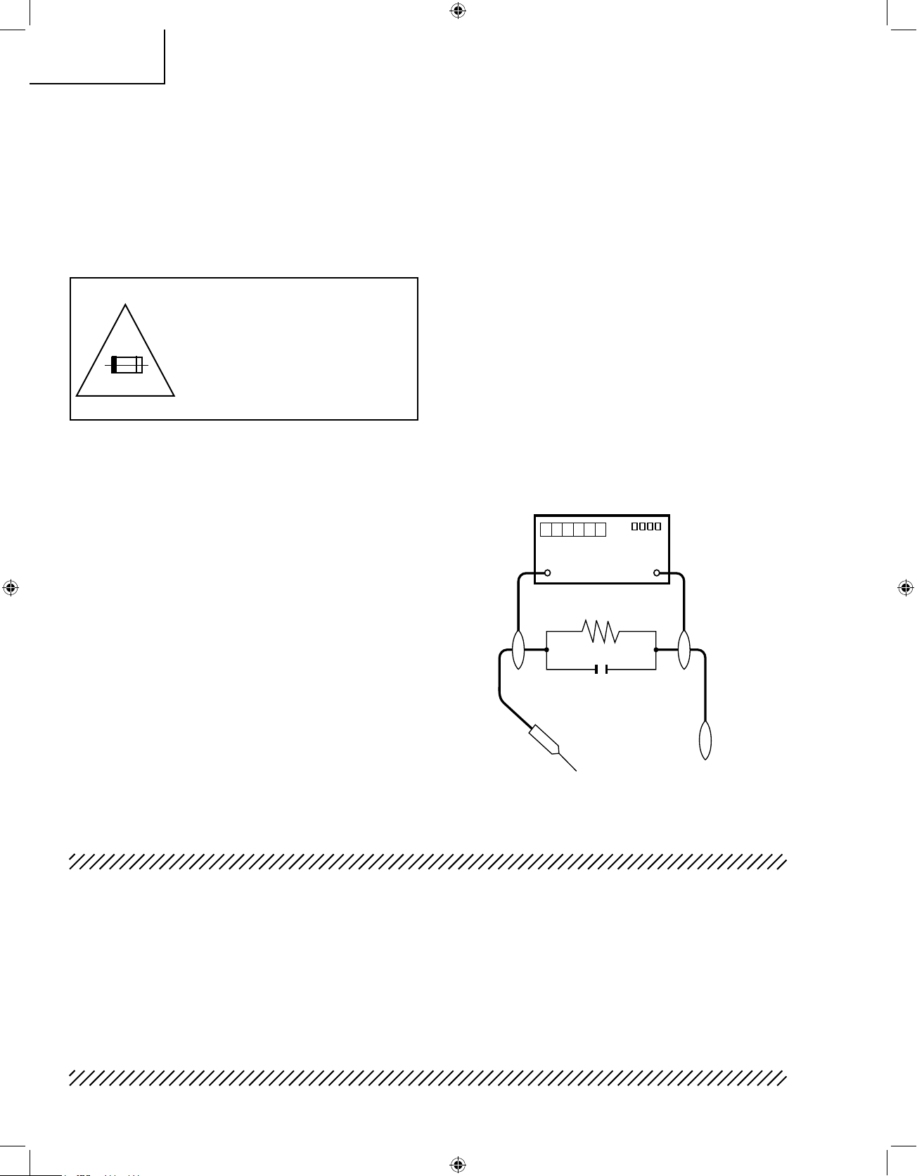
WARNING
1. For continued safety, no modification of any circuit
should be attempted.
2. Disconnect AC power before servicing.
BEFORE RETURNING THE RECEIVER
(Fire & Shock Hazard)
Before returning the receiver to the user, perform
the following safety checks:
1. Inspect all lead dress to make certain that leads are
not pinched, and check that hardware is not lodged
between the chassis and other metal parts in the
receiver.
2. Inspect all protective devices such as non-metallic
control knobs, insulation materials, cabinet backs,
adjustment and compartment covers or shields,
isolation resistor-capacitor networks, mechanical
insulators, etc.
3. To be sure that no shock hazard exists, check for
leakage current in the following manner.
•
Plug
the AC cord directly into a 120 volt AC outlet,
and connect the DC power cable into the receiver's
DC jack. (Do not use an isolation transformer for this
test).
•
Using two clip leads, connect a 1.5k ohm, 10 watt
resistor paralleled by a 0.15µF capacitor in series
with all exposed metal cabinet parts and a known
earth ground, such as electrical conduit or electrical
ground connected to an earth ground.
•
Use an AC voltmeter having with 5000 ohm per volt,
or higher, sensitivity or measure the AC voltage drop
across the resistor.
•
Connect the resistor connection to all exposed metal
parts having a return to the chassis (antenna, metal
cabinet, screw heads, knobs and control shafts,
escutcheon, etc.) and measure the AC voltage drop
across the resistor.
All
checks must be repeated with the AC cord plug
connection reversed. (If necessary, a nonpolarized
adaptor plug must be used only for the purpose of
completing these checks.)
Any reading of 0.75V peak (this corresponds to 0.5
mA. peak AC.) or more is excessive and indicates
a potential shock hazard which must be corrected
before returning the monitor to the owner.
DVM
AC SCALE
1.5k ohm
10W
TO EXPOSED
METAL PARTS
CONNECT TO
KNOWN EARTH
GROUND
0.15 µF
TEST PROBE
19K24U P1-17.indd 2 2007-9-13 11:14:28
Page 3
3
LC-19SK24U/U-W
LC-19SB24U/U-W
LC-19SB14U
LC-19D44U
PRECAUTION: POUR LA
PROTECTION CONTINUE
CONTRE LES RISQUES
D'INCENDIE, REMPLACER LE
FUSIBLE PAR UN FUSIBLE DE
MEME TYPE
F7501 (5A, 250V)
et
F7502 (2.5A, 250V).
AVIS POUR LA SECURITE
De nombreuses pièces, électriques et mécaniques,
dans les téléviseurs de l'afficharge à cristaux liquides
présentent des caractéristiques spéciales relatives à la
sécurité.
Ces caracténstiques ne sont souvent pas évidentes
à vue. Le degré de protection ne peut pas être
nécessairement augmentée en utilisant des pièces de
remplacement étalonnées pour haute tension, puissance,
etc.
Les pièces de remplacement qui présentent ces
caractéristiques sont identifiées dans ce manuel; les
pièces électriques qui présentent ces particularités sont
identifiées par la marque "
!
" et hachurées dans la
liste des pièces de remplacement et les diagrammes
schématiques.
Pour assurer la protection, ces pièces doivent être
identiques à celles utilisées dans le circuit d'origine.
L'utilisation de pièces qui n'ont pas les mêmes
caractéristiques que les pièces recommandées par
l'usine, indiquées dans ce manuel, peut provoquer des
électrocutions, incendies ou autres accidents.
PRECAUTIONS A PRENDRE LORS DE LA REPARATION
La réparation ne peut être effectuée que par un technicien spécialisé qui s'est
parfaitement accoutumé à toute vérification de sécurité et aux conseils suivants.
AVERTISSEMENT
1. Pour la sécurité continue, n'entreprendre aucune
modification de tout circuit.
2. Débrancher l'alimentation CA avant la réparation.
AVANT DE RENDRE LE RECEPTEUR A L’UTILISATEUR (Incendie et choc électrique)
Avant de rendre le récepteur à l'utilisateur, effectuer
les vérifications suivantes.
1. Inspecter tous les faisceaux de câbles pour s'assurer
que les fils ne soient pas pincés ou qu'un outil ne
soit pas placé entre le châssis et les autres pièces
métalliques du récepteur.
2. Inspecter tous les dispositifs de protection comme
les boutons de commande non-métalliques,
les isolants, le dos du coffret, les couvercles ou
blindages de réglage et de compartiment, les
réseaux de résistance-capacité, les isolateurs
mécaniques, etc.
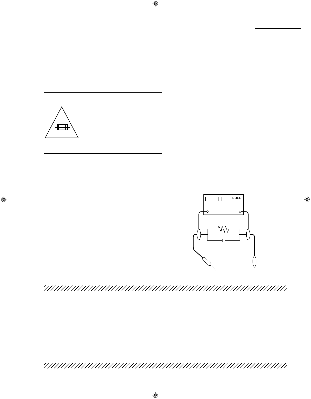
3. S'assurer qu'il n'y ait pas de danger d'électrocution
en vérifiant la fuite de courant, de la facon suivante:
•
B
rancher le cordon d'alimentation directem-ent à
une prise de courant de 120V. (Ne pas utiliser de
transformateur d'isolation pour cet essai).
•
A l'aide de deux fils à pinces, brancher une
résistance de 1.5kΩ 10 watts en parallèle avec un
condensateur de 0.15µF en série avec toutes les
pièces métalliques exposées du coffret et une terre
connue comme une conduite électrique ou une prise
de terre branchée à la terre.
•
Utiliser
un voltmètre CA d'une sensibilité d'au moins
5000Ω/V pour mesurer la chute de tension CA en
travers de la résistance.
•
Toucher avec la sonde d'essai les pièces métalliques
exposées qui présentent une voie de retour au
châssis (antenne, coffret métallique, tête des vis,
arbres de commande et des boutons, écusson,
etc.) et mesurer la chute de tension CA en travers
de la résistance. Toutes les vérifications doivent
être refaites après avoir inversé la fiche du cordon
d'alimentation. (Si nécessaire, une prise d'adpatation
non polarisée doit être utilisée dans le but de
terminer ces vérifications.)
La
tension de pointe mesurèe ne doit pas dépasser
0.75V (correspondante au courant CA de pointe de
0.5mA). Dans le cas contraire, il y a une possibilité
de choc électrique qui doit être supprimée avant de
rendre le récepteur au client.
A V
DVM
AC SCALE
1.5k ohm
10W
TO EXPOSED
METAL PARTS
CONNECT TO
KNOWN EARTH
GROUND
0.15 µF
TEST PROBE
19K24U P1-17.indd 3 2007-9-13 11:14:28
Page 4
4
LC-19SK24U/U-W
LC-19SB24U/U-W
LC-19SB14U
LC-19D44U
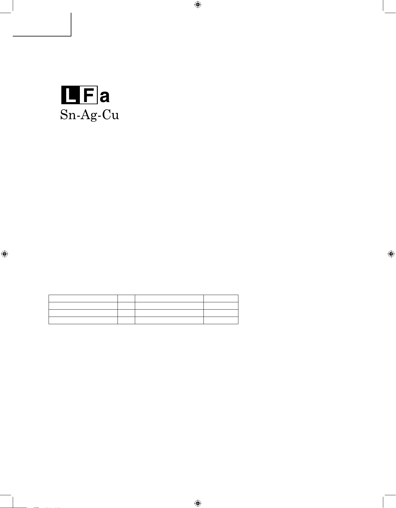
Precautions for using lead-free solder
1 Employing lead-free solder
"All PWBs" of this model employs lead-free solder. The LF symbol indicates lead-free solder, and is attached on
the PWBs and service manuals. The alphabetical character following LF shows the type of lead-free solder.
Example:
2 Using lead-free wire solder
When fixing the PWB soldered with the lead-free solder, apply lead-free wire solder. Repairing with conventional
lead wire solder may cause damage or accident due to cracks.
As the melting point of lead-free solder (Sn-Ag-Cu) is higher than the lead wire solder by 40°C, we recommend
you to use a dedicated soldering bit, if you are not familiar with how to obtain lead-free wire solder or soldering
bit, contact our service station or service branch in your area.
3 Soldering
As the melting point of lead-free solder (Sn-Ag-Cu) is about 220°C which is higher than the conventional lead
solder by 40°C, and as it has poor solder wettability, you may be apt to keep the soldering bit in contact with the
PWB for extended period of time. However, Since the land may be peeled off or the maximum heat-resistance
temperature of parts may be exceeded, remove the bit from the PWB as soon as you confirm the steady
soldering condition.
Lead-free solder contains more tin, and the end of the soldering bit may be easily corroded. Make sure to turn
on and off the power of the bit as required.
If a different type of solder stays on the tip of the soldering bit, it is alloyed with lead-free solder. Clean the bit
after every use of it.
When the tip of the soldering bit is blackened during use, file it with steel wool or fine sandpaper.
Be careful when replacing parts with polarity indication on the PWB silk.
Indicates lead-free solder of tin, silver and copper.
Lead-free wire solder for servicing
Part No,
★
Descr
iption Code
ZHNDAi123250E J
φ
0.3mm 250g(1roll) BL
ZHNDAi126500E J
φ
0.6mm 500g(1roll) BK
ZHNDAi12801KE J
φ
1.0mm 1kg(1roll) BM
19K24U P1-17.indd 4 2007-8-15 15:29:36
Page 5
5
LC-19SK24U/U-W
LC-19SB24U/U-W
LC-19SB14U
LC-19D44U
SpeCifiCationS
*1
Emergency alert messages via Cable are unreceivable.
*2
The dimensional drawings are shown on the inside back cover.
• As part of policy of continuous improvement, SHARP reserves the right to make design and specification changes for product
improvement without prior notice. The performance specification figures indicated are nominal values of production units.
There may be some deviations from these values in individual units.
LCD panel
Item
Model: LC-19SK24U/LC-19SK24U-W/LC-19SB24U/LC-19SB24U-W/LC-19SB14U
18.5o Active Matrix type a-Si TN LCD ( Screen size 181/
2
o
measured diagonally)
2W g 2
Number of dots
TV
Function
TV-standard (CCIR)
Receiving
Channel
VHF/UHF
CATV(analog)
Digital Terrestrial
Broadcast (8VSB)
Audio multiplex
Audio out
Terminals
INPUT 1
INPUT 2
INPUT 3
INPUT 4
ANTENNA
DIGITAL AUDIO OUTPUT
OSD language
Power Requirement
Power Consumption
Weight
Dimension
*2
(W g H g D)
Operating temperature
3,147,264 dots (1366 g 768 g 3 dots)
American TV Standard ATSC/NTSC System
VHF 2-13ch, UHF 14-69ch
1-125ch (STD, HRC, IRC)
2-69ch
BTSC System
COMPONENT in
AV in, S-VIDEO in
HDMI in with HDCP(480P, 720P/60Hz, 1080I/60Hz, VGA), HDMI Analog Audio in
15 pin mini D-sub female connector, PC Audio in (Ø 3.5 mm jack)
7
5 q U
nbalance, F Type g 1 for Analog (VHF/UHF/CATV) and Digital (AIR/CABLE)
Optical Digital audio output g 1 (Dolby Digital)
English/French/Spanish
AC 120 V, 60 Hz
e
32°F to e104°F (0°C to e40°C)
TV only
TV
+ stand
TV + stand
TV only
45 W (0.5 W Standby with AC 120V)
11.4 lbs./5.2 kg
10.3 lbs./4.7 kg
1
8
3
/16 g 12 19/32 g 2 61/64 inch
18
3
/16 g 1
4
11
/64 g 7 63/64 inch
Digital Cable
*1
(64/256 QAM)
1-135ch
Headphone
Ø 3.5 mm jack (Audio Output)
19K24U P1-17.indd 5 2007-9-28 13:51:42
Page 6
6
LC-19SK24U/U-W
LC-19SB24U/U-W
LC-19SB14U
LC-19D44U
SpeCifiCationS(Continued)
*1
Emergency alert messages via Cable are unreceivable.
*2
The dimensional drawings are shown on the inside back cover.
• As part of policy of continuous improvement, SHARP reserves the right to make design and specification changes for product
improvement without prior notice. The performance specification figures indicated are nominal values of production units.
There may be some deviations from these values in individual units.
LCD panel
Item
Model: LC-19D44U
18.5o Active Matrix type a-Si TN LCD ( Screen size 18
1
/
2
o
measured diagonally)
2W g 2
Number of dots
TV
Function
TV-standard (CCIR)
Receiving
Channel
VHF/UHF
CATV(analog)
Digital Terrestrial
Broadcast (8VSB)
Audio multiplex
Audio out
Terminals
INPUT 1
INPUT 2
INPUT 3
INPUT 4
ANTENNA
DIGITAL AUDIO OUTPUT
OSD language
Power Requirement
Power Consumption
Weight
Dimension
*2
(W g H g D)
Operating temperature
3,147,264 dots (1366 g 768 g 3 dots)
American TV Standard ATSC/NTSC System
VHF 2-13ch, UHF 14-69ch
1-125ch (STD, HRC, IRC)
2-69ch
BTSC System
COMPONENT in
AV in, S-VIDEO in
HDMI in with HDCP(480P, 720P/60Hz, 1080I/60Hz, VGA), HDMI Analog Audio in
15 pin mini D-sub female connector, PC Audio in (Ø 3.5 mm jack)
7
5 q U
nbalance, F Type g 1 for Analog (VHF/UHF/CATV) and Digital (AIR/CABLE)
Optical Digital audio output g 1 (Dolby Digital)
English/French/Spanish
AC 120 V, 60 Hz
e
32°F to e104°F (0°C to e40°C)
TV only
TV
+ stand
TV + stand
TV only
45 W (0.5 W Standby with AC 120V)
11.9 lbs./5.4 kg
10.1 lbs./4.5 kg
1
8
3
/16 g 12 19/32 g 3 1/32 inch
18
3
/16 g 14 11/64 g 7 63/64 inch
Digital Cable
*1
(64/256 QAM)
1-135ch
Headphone
Ø 3.5 mm jack (Audio Output)
19K24U P1-17.indd 6 2007-9-28 13:51:42
Page 7
7
LC-19SK24U/U-W
LC-19SB24U/U-W
LC-19SB14U
LC-19D44U
OPERATION MANUAL
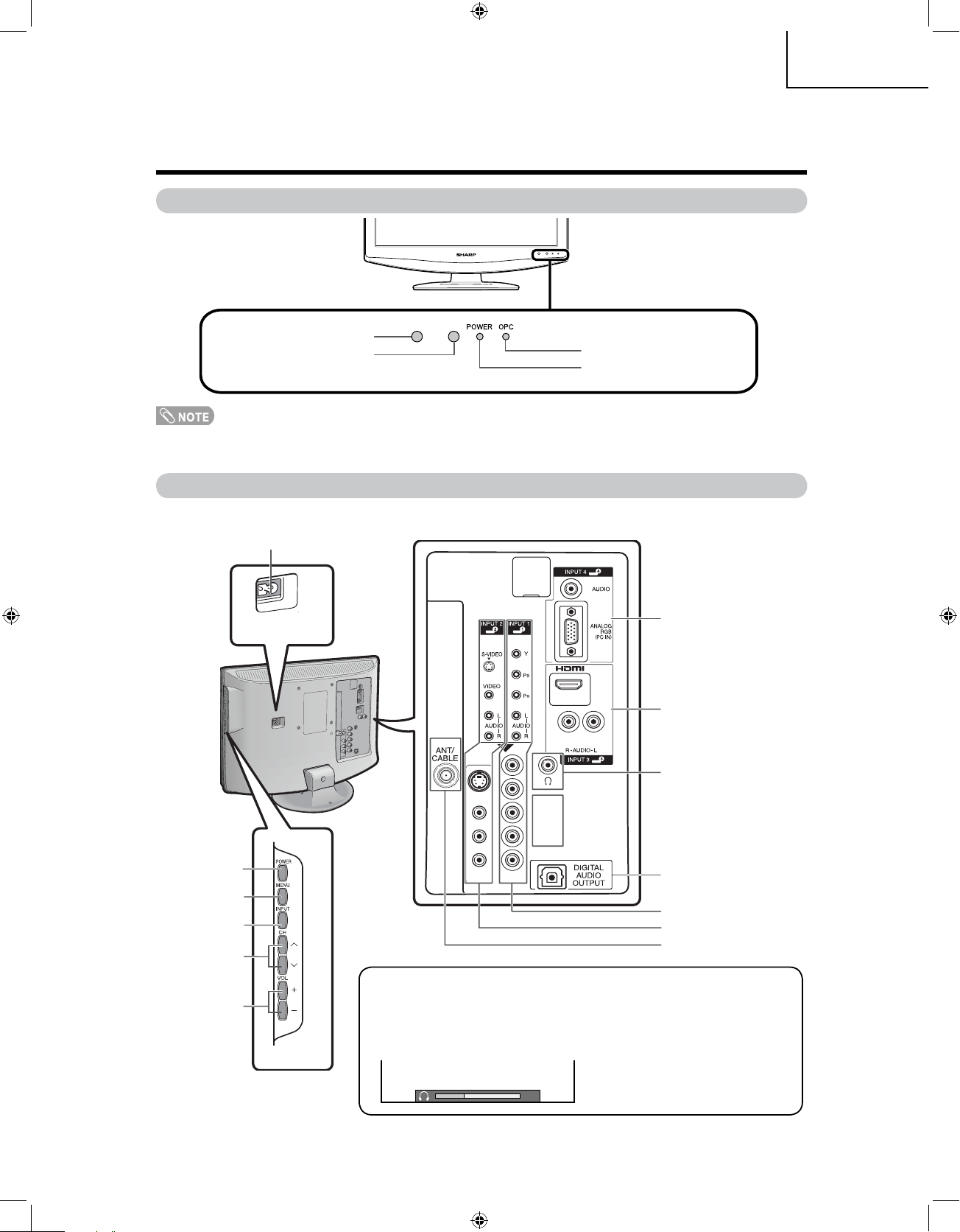
Part names
POWER
button
TV (Front)
Channel
buttons
(CHr/s)
Volume
buttons
(VOLk/l)
INPUT
button
POWER
indicator
OPC sensor*
Remote control sensor
*OPC: Optical Picture Control
OPC
indicator
TV (Side/Rear)
INPUT 4 terminals
(PC IN)
INPUT 1 terminals
DIGITAL AUDIO OUTPUT
terminal
Antenna/Cable
in
AC INPUT
terminal
INPUT
2 terminals
MENU
button
INPUT 3 terminals
(HDMI)
HEADPHONE
terminal
Regarding the headphone jack
• Use headphones with a stereo mini plug (Ø 3.5 mm).
• Be sure to unplug headphones from the jack when they are not in use.
• The speakers do not output volume when headphones are plugged in.
• You can set the volume to different levels for each input source.
Volume display when
headphones are plugged in
20
19K24U P1-17.indd 7 2007-8-15 15:29:38
Page 8
8
LC-19SK24U/U-W
LC-19SB24U/U-W
LC-19SB14U
LC-19D44U
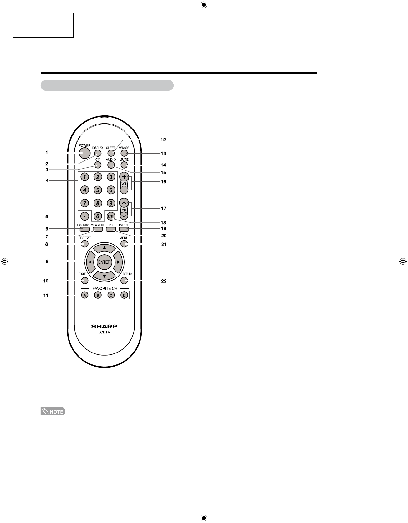
1 POWER: Switch the TV power on or enters standby.
2 DISPLAY:
Display the channel information.
3 CC:
Display captions from a closed-caption source.
4 0 – 9:
Set the channel.
5 • (DOT)
6 FLASHBACK:
Return to the previous channel or
external input mode.
7 VIEW MODE:
Select the screen size.
8 FREEZE:
Set the still image. Press again to return to
normal screen.
9 a/b/c/d/ENTER:
Select a desired item on the
screen.
10 EXIT:
Turn off the menu screen.
11 FAVORITE CH
A, B, C, D: Select
4 preset favorite channels in 4
different categories.
While watching, you can toggle the selected channels
by pressing A, B, C and D.
12 SLEEP:
Set the sleep timer.
13 AV MODE:
Select an audio or video setting. (When
the input source is TV, INPUT 1 or 2: STANDARD,
MOVIE, GAME, USER, DYNAMIC (Fixed), DYNAMIC.
When the input source is INPUT 3: STANDARD,
MOVIE, GAME, PC, USER, DYNAMIC (Fixed),
DYNAMIC. When the input source is INPUT 4:
STANDARD, PC, USER)
14 MUTE:
Mute the sound.
15 AUDIO: Selects
the MTS/SAP or the audio mode
during multi-channel audio broadcasts.
16 VOL k/l:
Set the volume.
17 CHr/s:
Select the channel.
18 ENT: Jumps
to a channel after selecting with the 0–9
buttons.
19 INPUT:
Select a TV input source. (TV, INPUT 1,
INPUT 2, INPUT 3, INPUT 4)
20 PC:
Quickly access to PC mode.
21 MENU:
Display the menu screen.
22 RETURN:
Return to the previous menu screen.
Remote control unit
• When using the remote control unit, point it at the TV.
Part names
19K24U P1-17.indd 8 2007-8-15 15:29:39
Page 9
9
LC-19SK24U/U-W
LC-19SB24U/U-W
LC-19SB14U
LC-19D44U
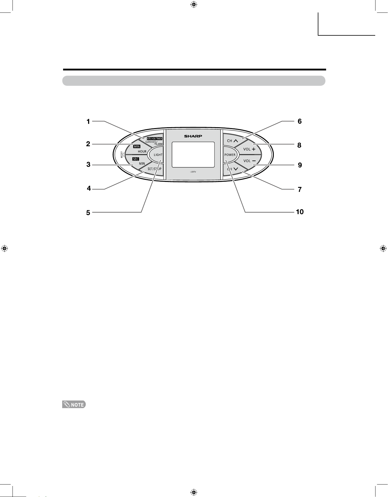
Kitchen Remote control unit (LC-19SK24U/LC-19SK24U-W/LC-19D44U)
1 KITCHEN TIMER/CLOCK SET/ALARM:
Set the kitchen timer, clock or alarm.
2 MIN/HOUR :
Set the minute of kitchen timer and the hour of clolck or alarm.
3 SEC/MIN :
Set the second of kitchen timer and the minute of clock or alarm.
4 SET/STOP :
Confirm setting or stop beeper sound.
5 LIGHT :
Light on the remote control LCD backlight.
6,7 CHr/CHs :
Select the channel.
8 VOL+ :
To increase the volume.
9 VOL- :
To decrease the volume.
10 POWER :
Switch the TV power on or enters standby.
• The method of using the Kitchcen Remote control unit, please see page 50~52 of operation manual.
Part names
19K24U P1-17.indd 9 2007-8-15 15:29:40
Page 10
10
LC-19SK24U/U-W
LC-19SB24U/U-W
LC-19SB14U
LC-19D44U
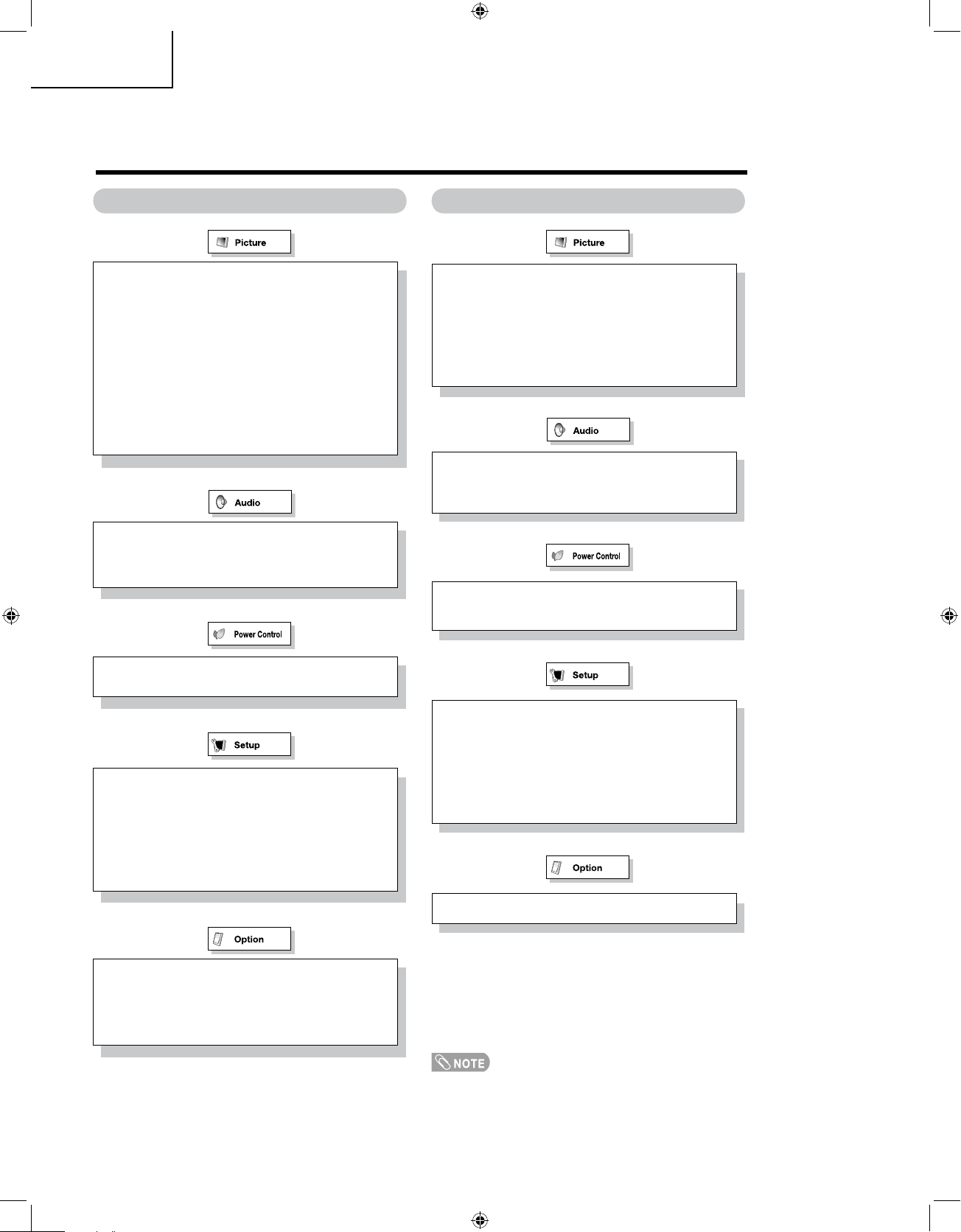
Menu items for TV/INPUT 1/2 Menu items for HDMI/PC-IN
Treble
Bass
Balance
Reset
• Some menu items may not be displayed depending on the
selected input source.
OPC
Backlight
Contrast
Brightness
Color
Tint
Sharpness
Advanced
C.M.S
Color Temp.
Film Mode
3D-Y/C
Monochrome
I/P Setting
Reset
Treble
Bass
Balance
Reset
OPC
Backlight
Contrast
Brightness
Advanced
C.M.S
Color Temp.
Monochrome
Reset
No Signal Off
No Operation Off
No Signal Off
No Operation Off
Power Management
EZ Setup
CH Setup
Antenna Setup-DIGITAL
Input Label
Parental CTRL
Position
Rotate
Language
Reset
Input Label
Parental CTRL
Position
PC Setup
HDMI Audio Select
HDMI Auto View
Rotate
Language
Reset
Audio Only
DNR
Audio Only
Digital Audio
Color System
Digital Caption Setup
Favorite CH
Basic adjustment settings
19K24U P1-17.indd 10 2007-8-15 15:29:41
Page 11
11
LC-19SK24U/U-W
LC-19SB24U/U-W
LC-19SB14U
LC-19D44U
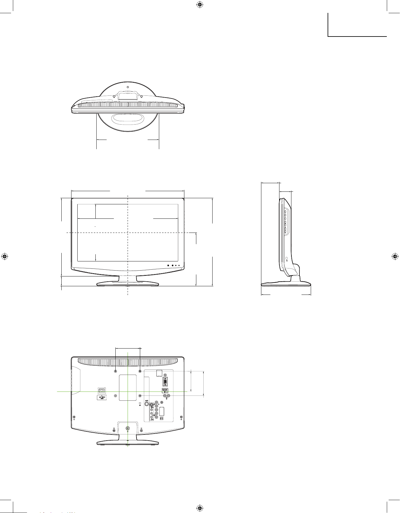
DIMENSIONS
Unit: inch (mm)
10 (254)
18
3
/16
(462)
12
19
/32
(320)
1
37
/64
(40)
16
7
/32
(411.8)
9
5
/32
(232.4)
14
11
/64
(360)
8
37
/64
(218)
3
15
/16
(100)
3
15
/16
(100)
3
17
/64
(83)
7
63
/64
(203)
2
61
/64
(75)
1
59
/64
(49)
LC-19SK24U/LC-19SK24U-W/LC-19SB24U/LC-19SB24U-W/LC-19SB14U
19K24U P1-17.indd 11 2007-8-15 15:29:42
Page 12
12
LC-19SK24U/U-W
LC-19SB24U/U-W
LC-19SB14U
LC-19D44U
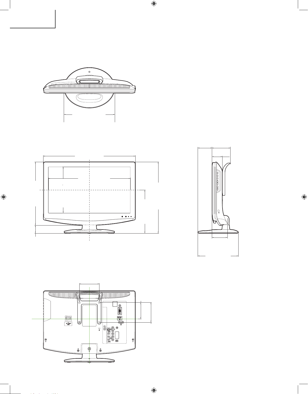
DIMENSIONS
LC-19D44U
Unit: inch (mm)
10(254)
18
3
/16
(462)
12
19
/32
(320)
1
37
/64
(40)
16
7
/32
(411.8)
9
5
/32
(232.4)
14
11
/64
(360)
8
37
/64
(218)
3
15
/16
(100)
3
15
/16
(100)
3
17
/64
(83)
7
63
/64
(203)
2
53
/64
(72) 3
5
/8
(92)
2
3
/64
(52)
3
1
/32
(77)
19K24U P1-17.indd 12 2007-8-15 15:29:43
Page 13
13
LC-19SK24U/U-W
LC-19SB24U/U-W
LC-19SB14U
LC-19D44U
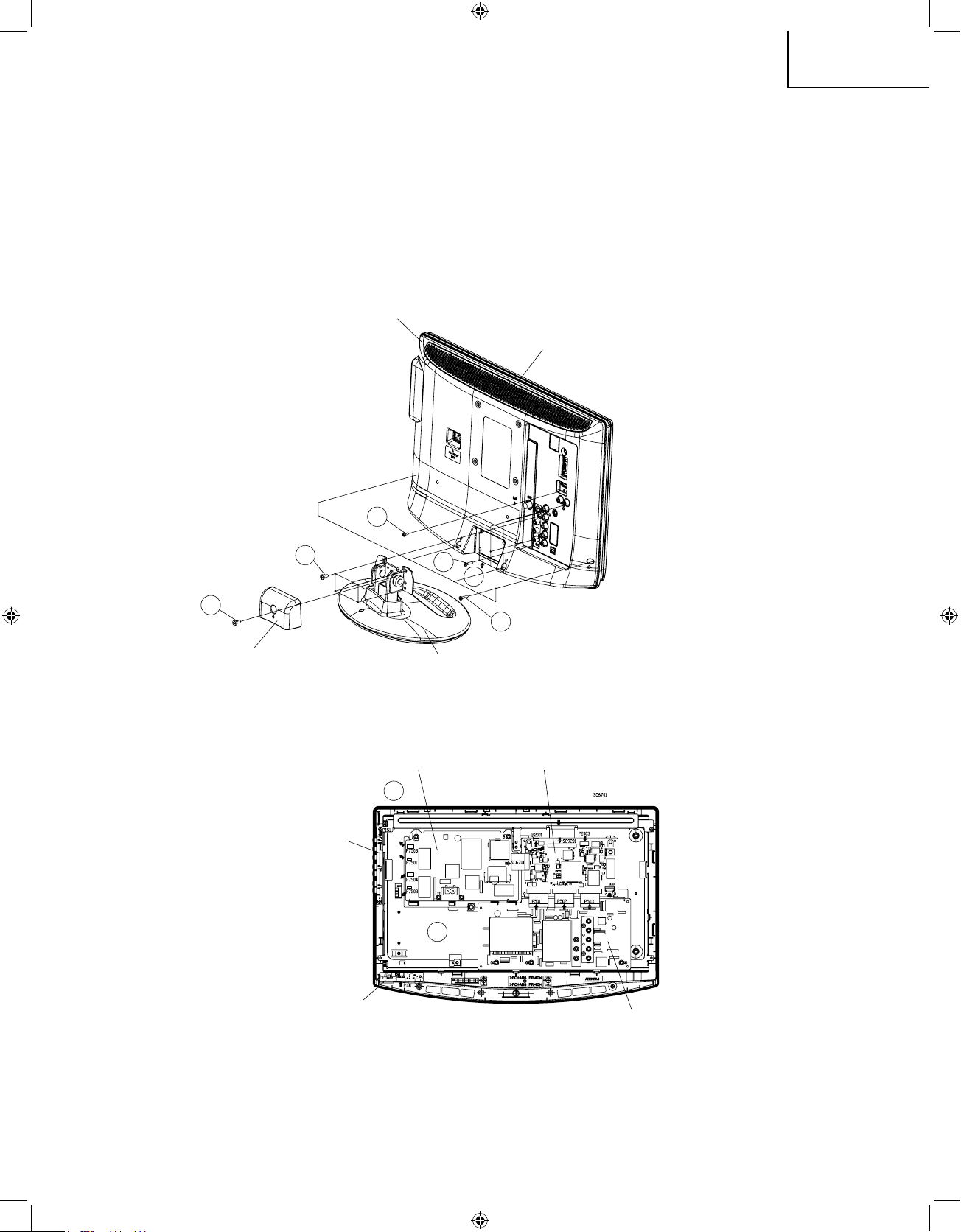
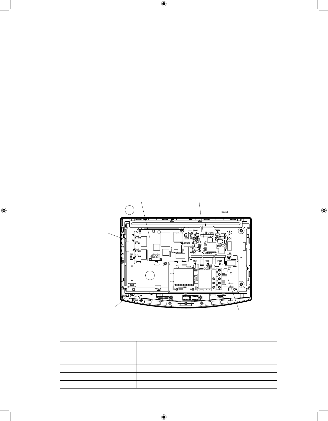
REMOVING OF MAJOR PARTS
(LC-19SK24U/LC-19SK24U-W)
1. Remove the Stand HINGI Cover fixing screw (1 pc.).
2. Remove the stand fixing screws (4 pcs.).
3. Remove the cabinet B fixing screws (10 pcs.).
4. Remove the cabinet B after opening from the direction of an arrow.
5. Disconnect all the connectors from all the PWBs.
Cabinet B
Cabinet A
3
3
3
2
1
5
5
4
Stand HINJI Cover
Stand
Inverter PWB
Main PWB
BTN PWB
LED PWB
Sub PWB
19K24U P1-17.indd 13 2007-9-13 10:25:45
Page 14
14
LC-19SK24U/U-W
LC-19SB24U/U-W
LC-19SB14U
LC-19D44U
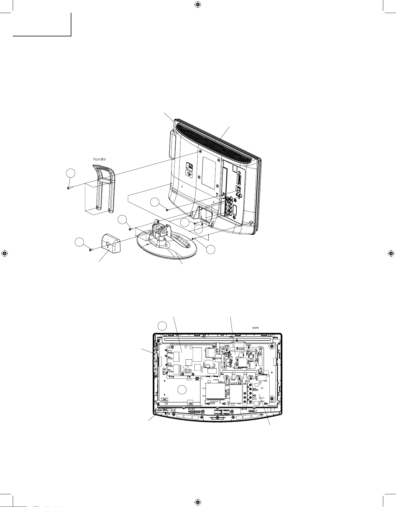
(LC-19D44U)
1. Remove the Stand HINGI Cover fixing screw (1 pc.) and the handle fixing screws (4 pcs).
2. Remove the stand fixing screws (4 pcs.).
3. Remove the cabinet B fixing screws (10 pcs.).
4. Remove the cabinet B after opening from the direction of an arrow.
5. Disconnect all the connectors from all the PWBs.
Cabinet B
Cabinet A
3
2
1
5
5
3
3
4
Stand HINJI Cover
Stand
Inverter PWB
Main PWB
BTN PWB
LED PWB
Sub PWB
1
19K24U P1-17.indd 14 2007-9-13 10:25:48
Page 15
15
LC-19SK24U/U-W
LC-19SB24U/U-W
LC-19SB14U
LC-19D44U
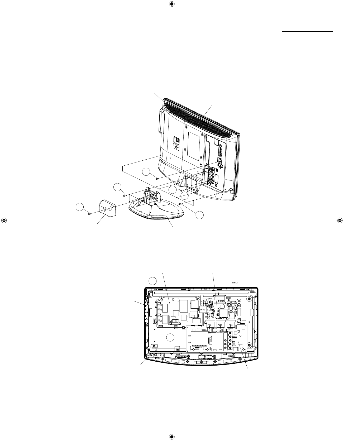
(LC-19SB24U/LC-19SB24U-W/LC-19SB14U)
1. Remove the Stand HINGI Cover fixing screw (1 pc.).
2. Remove the stand fixing screws (4 pcs.).
3. Remove the cabinet B fixing screws (10 pcs.).
4. Remove the cabinet B after opening from the direction of an arrow.
5. Disconnect all the connectors from all the PWBs.
Cabinet B
Cabinet A
3
2
1
5
5
3
3
4
Stand HINJI Cover
Stand
Inverter PWB
Main PWB
BTN PWB
LED PWB
Sub PWB
19K24U P1-17.indd 15 2007-9-13 10:25:50
Page 16
16
LC-19SK24U/U-W
LC-19SB24U/U-W
LC-19SB14U
LC-19D44U
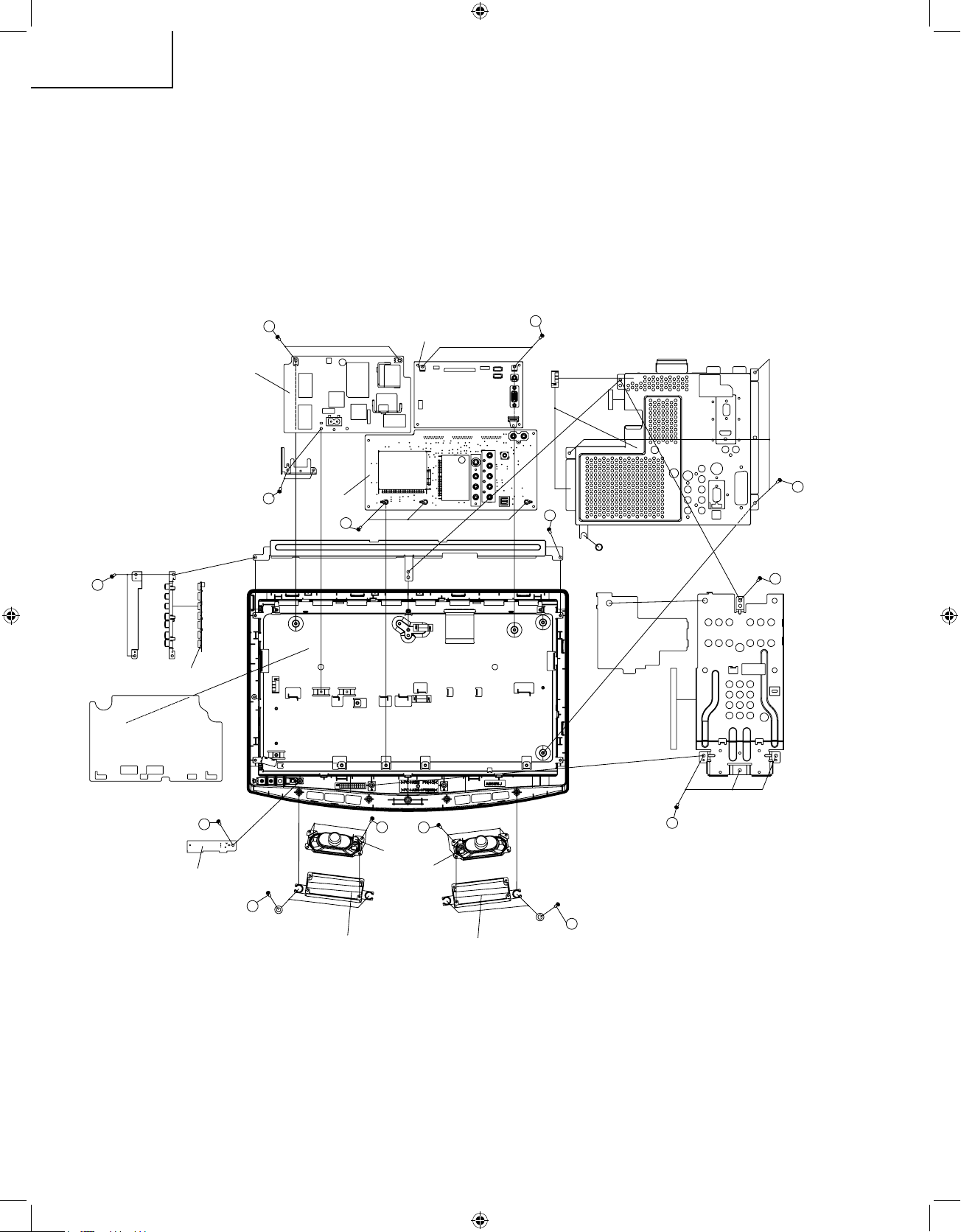
6. Remove the vesa angle fixing screws (4 pcs.).
7. Remove the 3 lock screws from Main Shield.
8. Remove the 9 lock screws from the sub PWB and main PWB and power PWB and AC angle. Detach the sub
PWB and main PWB and power PWB from LCD assembly.
9. Remove the 3 lock screws from the control button assembly and the source PWB Shield.
10. Remove the LED PWB fixing screws (1 pcs.).
11. Remove the 2 lock screws each from the right and left speakers ass’y and take out both the speakers ass’y.
12. Remove the 4 lock screws each from the right and left speaker angle.
Main PWB
Power PWB
Sub PWB
LED PWB
LED PWB
Speaker (L)
Speaker Angle (L)
Speaker Angle (R)
Speaker (R)
8
8
8
9
8
7
6
6
9
10
11
12
12
11
19K24U P1-17.indd 16 2007-8-20 14:38:34
Page 17
17
LC-19SK24U/U-W
LC-19SB24U/U-W
LC-19SB14U
LC-19D44U
Step Part No. Description
2 QCNW-E542WJZZ Extension Cab
le 23-pin Main (SC1201)-Sub (P501)
3 QCNW-E542WJZZ Extension Cab
le 23-pin Main (SC1202)-Sub (P502)
4 QCNW-E542WJZZ Extension Cab
le 23-pin Main (SC1203)-Sub (P503)
5 QCNW-D431WJZZ Extension Cab
le 15-pin Main (SC1204)-Power (SC7501)
6 QCNW-C458WJQZ Extension Cab
le 80-pin Main(SC9201)-Panel(CN1)
ネ
Precautions in servicing the side-B (backside) of the main PWB unit
1. Remove the lock screws (2 pcs.) from the main PWB, detach the PWB from the set, and then turn it over.
2. Connect the service-specific extension cable (QCNW-E542WJZZ) between the main PWB (SC1201) and the
sub PWB (P501).
3. Connect the service-specific extension cable (QCNW-E542WJZZ) between the main PWB (SC1202) and the
sub PWB (P502).
4. Connect the service-specific extension cable (QCNW-E542WJZZ) between the main PWB (SC1203) and the
sub PWB (P503).
5. Connect the service-specific extension cable (QCNW-D431WJZZ) between the main PWB (SC1204) and the
power PWB (SC7501).
6. Connect the service-specific extension cable (QCNW-C458WJQZ) between the main PWB (SC9201) and the
panel PWB (CN1).
ネ
Precautions in servicing the side-B (backside) of the power PWB unit
1. Remove the lock screws (4 pcs.) from the power PWB unit, detach the PWB from the set, and then turn it over.
2. Connect the service-specific extension cable (QCNW-D431WJZZ) between the power PWB (SC7501) and the
main PWB (SC1204).
ネ
Precautions in servicing the side-B (backside) of the sub PWB unit
1. Remove the lock screws (3 pcs.) from the sub PWB unit, detach the PWB from the set, and then turn it over.
2. Connect the service-specific extension cable (QCNW-E542WJZZ) between the sub PWB (P501) and the main
PWB (SC1201).
3. Connect the service-specific extension cable (QCNW-E542WJZZ) between the sub PWB (P502) and the main
PWB (SC1202).
4. Connect the service-specific extension cable (QCNW-E542WJZZ) between the sub PWB (P503) and the main
PWB (SC1203).
5
5
Inverter PWB
Main PWB
BTN PWB
LED PWB
Sub PWB
19K24U P1-17.indd 17 2007-8-20 14:38:35
Page 18
18
LC-19SK24U/U-W
LC-19SB24U/U-W
LC-19SB14U
LC-19D44U
ADJUSTING PROCEDURE OF EACH SECTION
The adjustment values are set to the optimum conditions at the factory before shipping .If a value should become
improper or an adjustment is required due to part replacement, make an adjustment according to the following
procedure.
1. After replacement of the any PWB and/or IC for repair, please note the following
1.1
When replacing the unit DUNTKE367MF01, make sure to prepare the new unit loaded with updated software.
1.2 Special Equipment
1.2.1 Renesas E8, the SUB microprocessor software Writer
1.2.2 Renesas M3A-2925G01, the MAIN microprocessor software Writer
1.2.3 Sophia systems DTV EJ-Writer, the MPEG Module software Writer
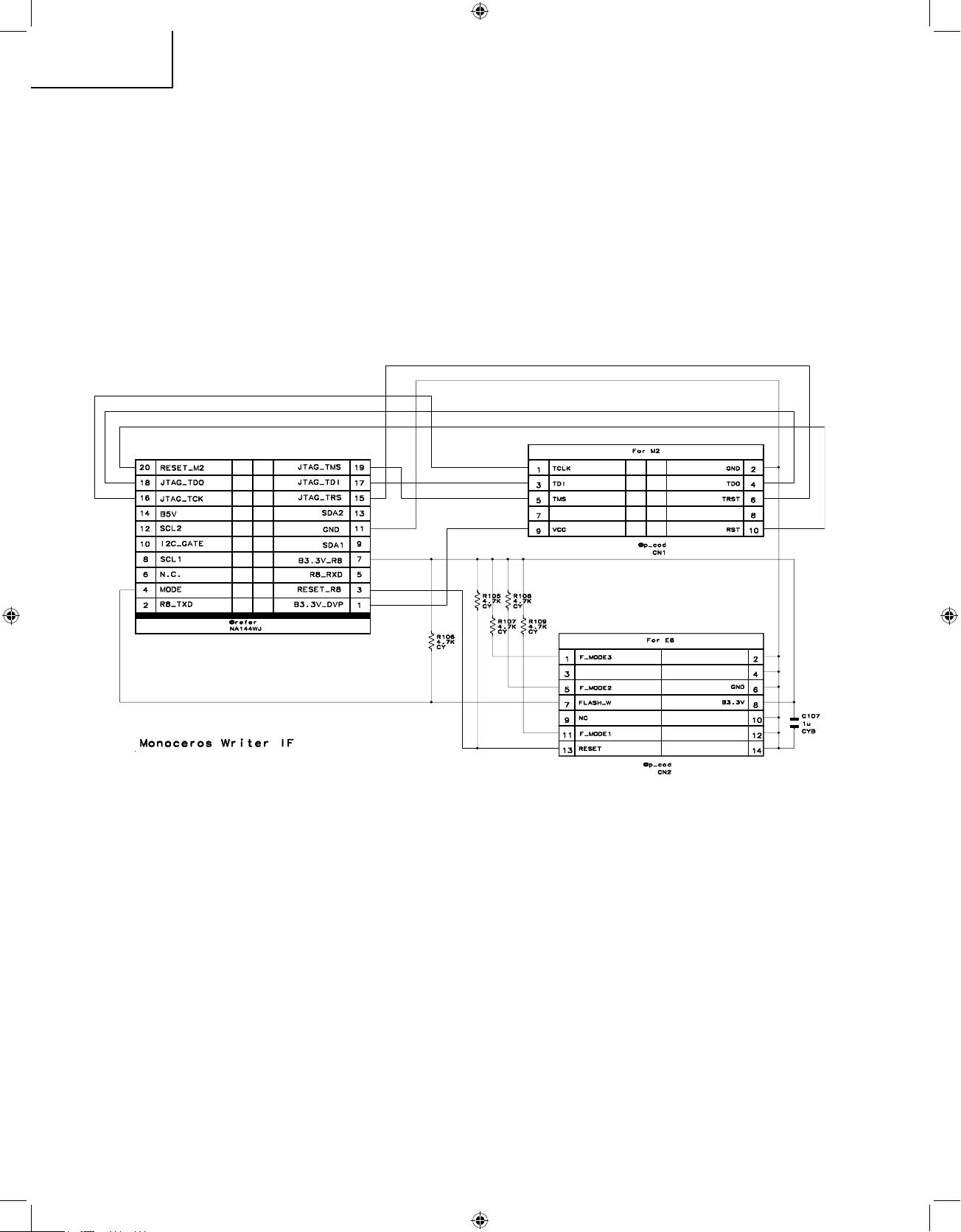
1.2.4 Convertor 1, please refer to following schematic and make one.
1.2.5 Convertor 2, please refer to following instruction and make one.
DTV EJ Writer (SH2/SH3) TUNER port
1 - - - - - - - - - - - - - - - - - - - - - - - - - - - - - - - - - - - 1
2 - - - - - - - - - - - - - - - - - - - - - - - - - - - - - - - - - - - 2
3 - - - - - - - - - - - - - - - - - - - - - - - - - - - - - - - - - - - 3
4 - - - - - - - - - - - - - - - - - - - - - - - - - - - - - - - - - - - 4
5 - - - - - - - - - - - - - - - - - - - - - - - - - - - - - - - - - - - 5
6 - - - - - - - - - - - - - - - - - - - - - - - - - - - - - - - - - - - 6
7 - - - - - - - - - - - - - - - - - - - - - - - - - - - - - - - - - - - 7
8 - - - - - - - - - - - - - - - - - - - - - - - - - - - - - - - - - - - 8
9 - - - - - - - - - - - - - - - - - - - - - - - - - - - - - - - - - - - 9
10 - - - - - - - - - - - - - - - - - - - - - - - - - - - - - - - - - - 10
11 - - - - - - - - - - - - - - - - - - - - - - - - - - - - - - - - - - 11
12 - - - - - - - - - - - - - - - - - - - - - - - - - - - - - - - - - - 12
19K24U P18-57.indd 18 2007-8-15 15:30:31
Page 19

19
LC-19SK24U/U-W
LC-19SB24U/U-W
LC-19SB14U
LC-19D44U
19K24U P18-57.indd 19 2007-8-15 15:30:33
Page 20

20
LC-19SK24U/U-W
LC-19SB24U/U-W
LC-19SB14U
LC-19D44U
2. Upgrading of each microprocessor software
2.1 Sub microprocessor software version upgrade
1). Install “E8 Emulator Debugger” in CD-ROM.
2). access http://www.renesas.com/fmwk.jsp?cnt=/download_search_results.jsp&fp=/support/downloads/
download_results&layerId=1612 to download following two update packages:
1
E8 Emulator Software V.2.09 Release 02 for M16C, H8 Upgrade (Debugger package version)
Issue date:2007-2-22 48.3M
2
High-performance Embedded Workshop V.4.02.00 Upgrade
Issue date:2006-12-10 52.5M
Install these packages.
3). connect E8 Emulator Debugger to PC from USB port.(drivers at folder”E8 Emulator Debugger”)
4). connect E8 writer to LCD’s 20PIN port which near INPUT4 terminal, use convertor1.
5). run “High Performance Embeded Workshop” in start menu.
6). choose “Browse to another project work”, and select “R8C_2A” in folder “R8C_2A”.
If second time, you can select “open a recent project work”.
Choose “OK”.
19K24U P18-57.indd 20 2007-8-15 15:30:34
Page 21

21
LC-19SK24U/U-W
LC-19SB24U/U-W
LC-19SB14U
LC-19D44U
7). Then enter “Emulator settings”, the Device is R5F212B8, mode is “program flash”. please choose “Power
Target from E8(MAX 300mA)” and select 3.3V, and choose OK.
8). connecting start, after connected it will enquire a ID CODE, input all zero (0000000000000000).
19K24U P18-57.indd 21 2007-8-21 13:25:52
Page 22

22
LC-19SK24U/U-W
LC-19SB24U/U-W
LC-19SB14U
LC-19D44U
9). Next display
10). enter menu ”debug”->”debug settings…” -> “add” to add firmware file (Mot file).
19K24U P18-57.indd 22 2007-8-15 15:30:36
Page 23

23
LC-19SK24U/U-W
LC-19SB24U/U-W
LC-19SB14U
LC-19D44U
After it you can see firmware in “Download modules”.
11). Enter menu ”Debug”->”DOWNLOAD modules” and select the firmware.
19K24U P18-57.indd 23 2007-8-15 15:30:37
Page 24

24
LC-19SK24U/U-W
LC-19SB24U/U-W
LC-19SB14U
LC-19D44U
12). After updating
Then shut down “High Performance Embeded Workshop”, unplug 20PIN connector, and E8 firmware updating
finish.
2.2 Main microprocessor software version upgrade
2.2.1 Please find the folder named PD308 on the SM Server:
Ftp://172.30.48.21/NSEC_Design/LC-19D44U/Service_Manual
19K24U P18-57.indd 24 2007-8-21 13:26:29
Page 25
25
LC-19SK24U/U-W
LC-19SB24U/U-W
LC-19SB14U
LC-19D44U
2.2.2 Install software: \PD308\PD308SDI_
暂定版
\DISK1\setup.exe
After installation, connect writer to PC, the drivers at C: \Renesas\PD308SDI\DRIVERS\ (default install path)
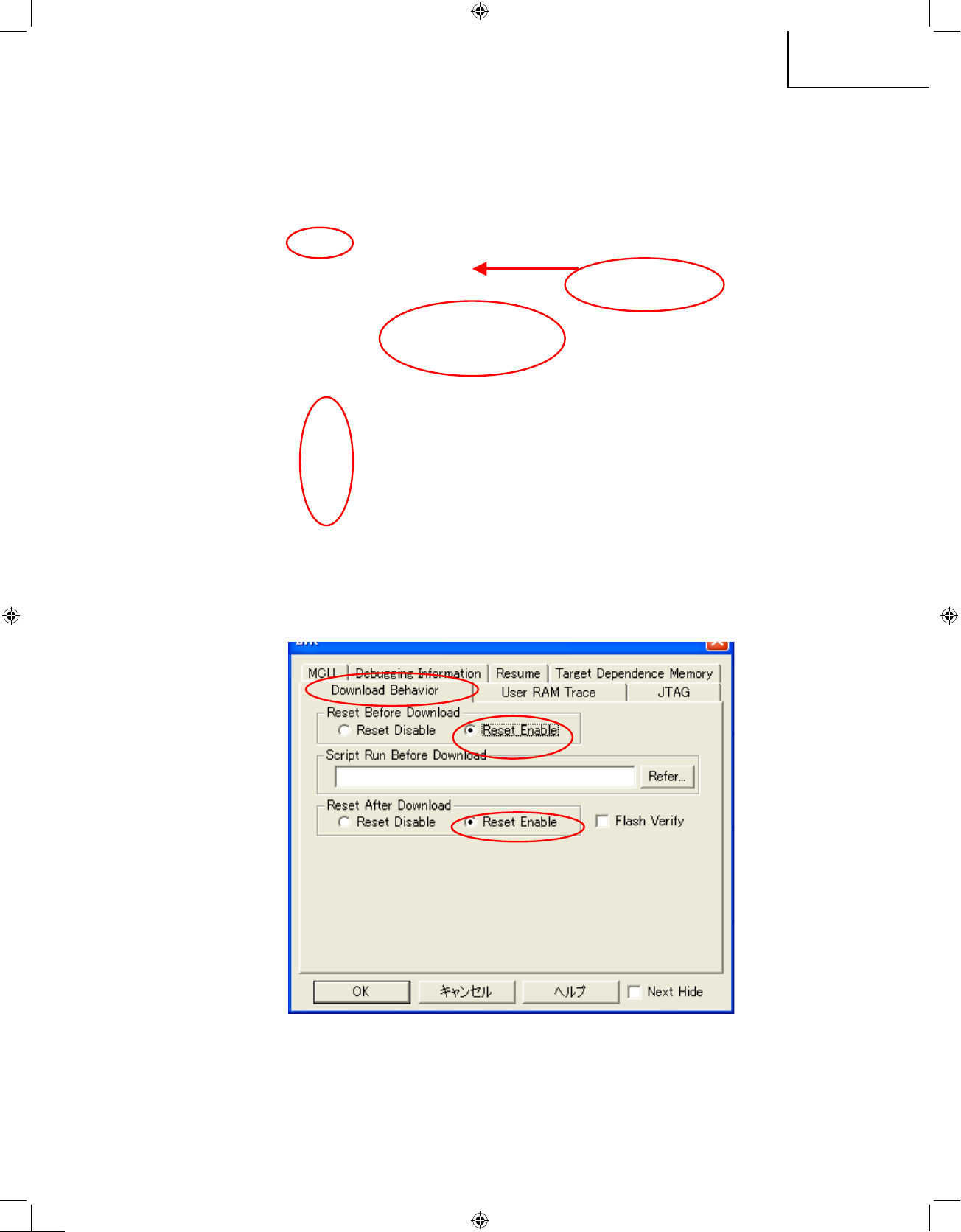
2.2.2.1 MCU settings/Download Behavior settings
MCU FILE at PD308\MCUFiles\66608.mcu
19K24U P18-57.indd 25 2007-8-15 15:30:38
Page 26
26
LC-19SK24U/U-W
LC-19SB24U/U-W
LC-19SB14U
LC-19D44U
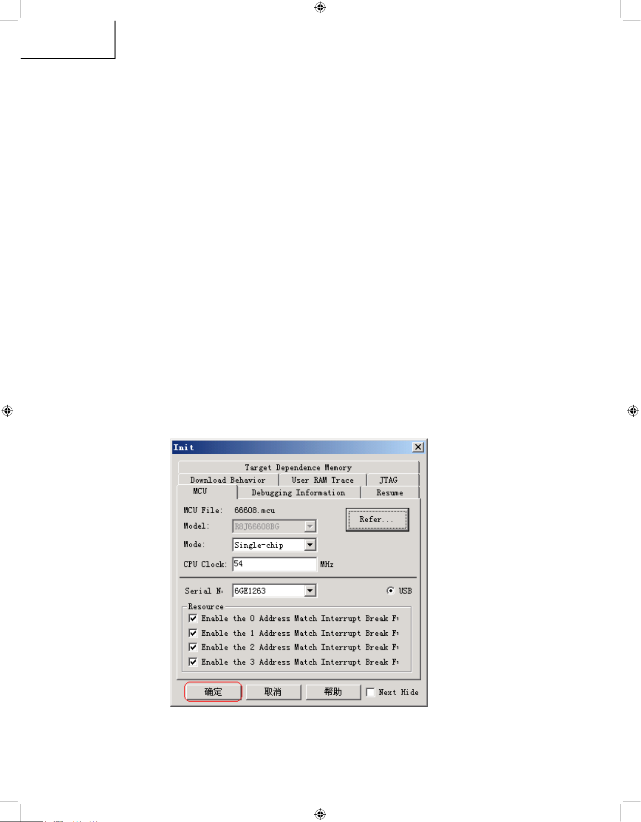
2.2.2.2 Target Dependence Memory setting
Type=Read/Write, Size=ALL, TOP=0, Bottom=DFFF → Add
Type=Read/Write, Size=Word/Lword, TOP=8000000, - -Bottom=9FFFFF → Add
2.2.2.3 Make the FTD file(FLASH Memory)
Need two files: PD308\FDDFiles\DVP-M2_FTD_061221.scr
PD308\FDDFiles\S29AL008B_M32C.FDD
Type = Flash ROM ->Create
Device File: Refer-> S29AL008B_M32C.FDD
ROM Activate Script File: Refer-> DVP-M2_FTD_061221.scr
19K24U P18-57.indd 26 2007-8-15 15:30:39
Page 27

27
LC-19SK24U/U-W
LC-19SB24U/U-W
LC-19SB14U
LC-19D44U
And other settings as follow
OK and save as M2_1M.ftd file
19K24U P18-57.indd 27 2007-8-21 13:27:14
Page 28
28
LC-19SK24U/U-W
LC-19SB24U/U-W
LC-19SB14U
LC-19D44U
2.2.2.4 “Add” Flash ROM
Setting finish.
2.2.2.5 Update firmware:
1
. Connect M2 writer to LCD’s 20PIN port which near INPUT4 terminal, use convertor1
2
. Plug AC cord, make sure power indicator on.
3
. Run PD308SDI in start menu.
Then choose OK.
19K24U P18-57.indd 28 2007-8-15 15:30:40
Page 29

29
LC-19SK24U/U-W
LC-19SB24U/U-W
LC-19SB14U
LC-19D44U
4
. If the connection correct, it will display as below:
5
. Enter menu “file”->“download”> “rom data”, and select firmware(MOT file).
19K24U P18-57.indd 29 2007-8-21 13:29:40
Page 30

30
LC-19SK24U/U-W
LC-19SB24U/U-W
LC-19SB14U
LC-19D44U
6
. Wait about 30 seconds, it up to 100%
7
. Shut down PD308SDI.
8
. Unplug AC cord and 20Pin connector.
3. MPEG2 module software version upgrade
Install soft in CD-ROM : WATCHPOINT-EJW\Disk1\SETUP.EXE
USB Driver: CD-ROM folder “USB Driver”.
19K24U P18-57.indd 30 2007-8-15 15:30:41
Page 31

31
LC-19SK24U/U-W
LC-19SB24U/U-W
LC-19SB14U
LC-19D44U
3.1. Supply AC power to writer and connect it to PC, connect writer to sub pwb by convertor 2
3.2. Run “EJ-Writer DTV” in start menu.
1
. Select DTV_sx_v2.dbg in default install path.
2
. AC in and power on, press “Enter”.
19K24U P18-57.indd 31 2007-8-21 15:42:59
Page 32

32
LC-19SK24U/U-W
LC-19SB24U/U-W
LC-19SB14U
LC-19D44U
3
. Press CMD and select “BATCH”.
19K24U P18-57.indd 32 2007-8-21 15:43:00
Page 33

33
LC-19SK24U/U-W
LC-19SB24U/U-W
LC-19SB14U
LC-19D44U
4
.press the green character, and press enter
19K24U P18-57.indd 33 2007-8-21 15:43:01
Page 34

34
LC-19SK24U/U-W
LC-19SB24U/U-W
LC-19SB14U
LC-19D44U
5
. select “Resource” ->“Flash Memory”->“Device Setup” in menu. The detail setting as follow:
Detail setting please refer to “EJ-Writer setting. pdf” in ftp://172.30.48.21/NSEC_Design/LC-19D44U/
Service_Manual/
19K24U P18-57.indd 34 2007-8-21 15:43:01
Page 35

35
LC-19SK24U/U-W
LC-19SB24U/U-W
LC-19SB14U
LC-19D44U
6
. Then press the Start, and begin chip erase
19K24U P18-57.indd 35 2007-8-21 15:43:01
Page 36

36
LC-19SK24U/U-W
LC-19SB24U/U-W
LC-19SB14U
LC-19D44U
7
. After erase the display as follow:
8
. Press MEM, and press to check the DUMP, all of them are “FF”
19K24U P18-57.indd 36 2007-8-21 15:43:02
Page 37

37
LC-19SK24U/U-W
LC-19SB24U/U-W
LC-19SB14U
LC-19D44U
9
. Select “Resource”->“Download”, and “Add” mot file:
0
. Press Download, begin writer data
19K24U P18-57.indd 37 2007-8-21 15:43:02
Page 38

38
LC-19SK24U/U-W
LC-19SB24U/U-W
LC-19SB14U
LC-19D44U
q
. Waiting about 4 minutes, it’s up to 100%, writing finish.
check the memory dump again, the data appeared
w
. Close WATCHPOINT, and save the project file
e
. unplug the AC cord and connector.
19K24U P18-57.indd 38 2007-8-21 15:43:03
Page 39

39
LC-19SK24U/U-W
LC-19SB24U/U-W
LC-19SB14U
LC-19D44U
4. Adjustment procedure
4.1 Plug the AC power cord directly into a wall outlet.
4.2 Calling the adjustment process mode
There are two ways to call this mode.
∗
Turn on the power and press the “ADJUST PROCESS” key on the remote controller.
∗
For servicing: Hold down the INPUT key and VOL (−) key at once, and turn on the power switch.(“K”
appears at the top left of the screen to indicate the inspection process mode.)---Press the CH (s)key
and VOL(−)key at once.(The adjustment process mode screen shows up.)_To quit, turn off the power.
(Or turn off the power switch or turn off the remote controller.)
4.3
Key operation in the adjustment process
Basic operation
Selecting the receiving channels
∗
Using the CH(r)/(s) keys, turn up and down an actual receiving channel.
Snap press: The channels are turned up and down one by one .
Continuous press: The next receivable channel is searched.
∗
Various adjustments: The items are adjusted one by one by selecting on the menu screen and using
the cursor key and VOL(+)(−) keys
∗
With the CURSOR UP/DOWN keys, select an adjustment item.
∗
Using the MENU key, the adjustment items are selected one after another. When the bottom item on
a page is already selected and the MENU key is pressed, the top item on the next page is selected.
∗
If any item on a page is selected and the preset key is pressed, the top item on the next page is selected.
Page1- Page2- Page3- Page7- Page9- Page10…..
∗
If any item on a page is selected and the manual memory key is pressed, the top item on the same
page is selected.
∗
Using the CURSOR LEFT/RIGHT keys and VOL(+)(−) keys, turn up and down the setting of a
selected item.
Hierarchical shift
∗
When the ENTER key is pressed on any item other than I2C DATA on page 4,the setting page of the
item shows up.
∗
To quit the setting page, press the front screen key.
4.4
Adjustment
4.4.1 AD TRANSFORM LEVEL Adjustment
4.1.1.1 Input 1080i signal
1
Input 1080i color bar signal (75%)
Signal generation: LEADER LT448
Signal: color BAR.
Setting: 02: 1080i/59.94(30sf)
H: 33.72 KHz V: 29.97Hz
Note: Please use the third color Bar of LT448 generator
2
Adjusting AUTO GAIN-OFFSET in page 3 of DVP (M2-HD) to RUN .
When “AUTO GAIN-OFFSET OK” appears , this adjustment is complete
4.1.1.2 Input 480i signal
1
Input 480i color bar signal (75%)
Signal: color BAR.
Setting: 15: 480i/60
H: 15.73 KHz V: 29.97Hz
Note: Please use the third color Bar of LT448 generator
2
Adjusting AUTO GAIN-OFFSET in page 4 of DVP (M2-SD) to RUN .
When “AUTO GAIN-OFFSET OK” appears , this adjustment is complete
4.1.1.3 Input PC XGA signal
1
Input XGA color bar signal (RGB)
Signal generation: LEADER LT448
19K24U P18-57.indd 39 2007-8-15 15:30:47
Page 40

40
LC-19SK24U/U-W
LC-19SB24U/U-W
LC-19SB14U
LC-19D44U
Signal: color BAR (SATURATION 75%)
Setting: 28: XGA
H: 48.36KHz V: 60Hz
SYNC: OFF
Note: Please use the color Bar of SATURATION
2
Adjusting AUTO GAIN-OFFSET in page 5 of DVP(M2-PC)to RUN .
When “AUTO GAIN-OFFSET OK” appears , this adjustment is complete
NOTE: If want to set all item to ON,please set to RUN in ADJUST PROCESS.
4.5
TEMP Adjustment
4.5.1 Receive US-10ch(JPN-8ch) the standard color bar signal
4.5.2 See if the “YDATA” reading (maximum) on Adjustment Process Page 1 is within the range in the
follow table. If not, adjust the “TEMP ALL” setting on the same page to have the “YDATA” reading
(maximum) within this range.
MODEL A3KL19SK24U
SETTING VALUE (NTSC) 96-100
Refence
(Adjustment Process Menu Page 1)
0 1 2 3 4 5 6 7 8 9 10 11 12 13 14 15 16 17 18 19 20 21 22 23 24 25 26
0 D V P 1
1
●
T A M P 1 L 9 6
2 Y D A T A 9 8
3 T A M P 1 H 1 0 0
4 T A M P A L L O F F
5 N T S C T A M P 1 7 7
6 P A L - M T A M P 6 4
7 P A L - N T A M P 6 4
19K24U P18-57.indd 40 2007-8-15 15:30:48
Page 41

41
LC-19SK24U/U-W
LC-19SB24U/U-W
LC-19SB14U
LC-19D44U
4.5.3 Common bias Adjustment
1
Feed in built-in signal (See follow picture)
2
Adjust the “COM BIAS” setting so that the peak-to-peak of the wave be minimized.
㪎
㪍
㪎
19K24U P18-57.indd 41 2007-8-15 15:30:50
Page 42

42
LC-19SK24U/U-W
LC-19SB24U/U-W
LC-19SB14U
LC-19D44U
4.5.4 White balance adjustment
Adjustment item Adjustment conditions Adjustment procedure
1 Setting Backlight: +16
(MAX)
For detailed adjustment procedure refer to "Kameyama Model Integral WB Adjustment
Specifications".
1) Make the following settings for the set.
AV MODE: [DYNAMIC]
Backlight: +16
Aging time: Min. 30 minutes
2) Connect the white balance adjustment tool to the set.
3) The cross is displayed by execute command of RS232C and the probe position is
set to the center of the screen(please attention the operation manual of CA210).
4) The cross is disappeared by execute command of RS232C.
Adjusting the picture by execute command of RS232C
2 Automatic adjust-
ment execution
[Adjustment prcedure]
1) Using the remote controller,transmit the "monitor adjustment process" code.
2) Set the 6
th
point to the specified gradation level,With the strongest color being fixed,
turn down the R,G and B settings to their reference levels.
3) Set the 5
th
point to the specified gradation level.
Correct the G setting (304 x 6th point G setting /816) (rounded off), and make the R
and B settings to their reference levels.
* Initial R, G and B settings at point 6: Gradation level set at 816
* Initial R and B settings at points 5:Correct the setting same remainder of RGB setting
at each point (This is because the adjustment is made to achieve the same remainder
of RGB setting/4 at each point).
[Adjustment value]
As per the "standard set" submitted by Engineering Department
[Adjustment reference] Instrument:[Minolta CA-210] Engineering instrument
Level Reference Adj.spec Ins.spec
point 6 816
X=0.272
±
0.001
±
0.002
y=0.277
point 5 304
X=0.272
±
0.002
±
0.004
y=0.277
Note Set conditions for inspection
AV MODE: [DYNAMIC] (Reset)
Monochrome: ON
Aging Time: Min. 30 minutes
4.6 Factory setting
4.6.1 Making factory settings
Use the adjustment remote controller for the factory settings.
4.6.1.1 Hold on the remote controller’s FACTORY SETTING key.
4.6.1.2
Sever seconds later, "SETTING COMPLETE""TV VER *.**" appears at the center of the screen.
If background of screen is green,the settings are complete.
4.6.1.3 Power off the set.
Note: Do not turn on the power once the factory settings have been made. Otherwise the factory
setting must be made again.
4.7 Software version
The software version will be reported at the Conversion Judgment Meeting. Possible modifications that will
follow will be reported using the Modifications Report.
∗
Main microprocessor
∗ Monitor microprocessor
∗ EDIT data(HDMI/analog RGB)
SETTING COMPLETE
TV VER ∗.
∗∗
19K24U P18-57.indd 42 2007-8-15 15:30:51
Page 43

43
LC-19SK24U/U-W
LC-19SB24U/U-W
LC-19SB14U
LC-19D44U
PUBLIC MODE SETTING PROCEDURE
1. How to start Public Mode
•
There are the following two ways to get the public mode setup screen displayed.
1
In the adjustment process mode, turn on "HOTEL MODE". Also press the "CH (r)" and "VOL (+)" keys
on the set at once and turn on the power.
2
1) Press the "INPUT" and "V
OL (+)" keys on the set at once and turn on the power.
2) Get the password input screen displayed.
Procedure
•
The input starts with the leftmost digit.
•
Use the numeric keys [1] thru [9] and [0] keys on the remote con-
troller. The other keys are not acceptable.
•
With a numeric-key input, "–" will change to "✽". The input position
will move one digit to the right.
•
With all the 3 digits entered, the password will be verified.
3) The 3-digit password is now verified.
The password [0] [2] [7] provides for the public mode screen. (This screen comes on with whatever ad-
justment process settings.)
With any other passwords, the screen changes to the normal mode.
— — —
✽
— —
✽
✽
✽
19K24U P18-57.indd 43 2007-8-15 15:30:51
Page 44

44
LC-19SK24U/U-W
LC-19SB24U/U-W
LC-19SB14U
LC-19D44U
2. How to exit Public Mode
There are the following ways to quit the public mode setup screen.
•
Turn off "HOTEL MODE" in the adjustment process mode. (✩) ←
This way alone is not for quitting the setup
screen, but for quitting the mode itself.
•
Turn off the power with the "POWER" key. (★)
•
Select "ENTER". (★)
★
... "HOTEL MODE" stays on in the adjustment process mode.
✩
... The settings will be back to the factory ones.
3. Public Mode Setting Values
•
With the factory settings made, the public mode settings get initialized. (The adjustment process remains intact.)
4. Public Mode Menu
The guidance is not displayed onscreen.
Setup procedure
•
To move the cursor up and down, use the "cursor UP/DOWN" key (remote controller) and "CH (
r
)/(s)" key
(remote controller and set).
•
To change the settings, use the "cursor RIGHT/LEFT" key (remote controller) and "VOL (+)/(–)" key (remote
controller and set).
•
To save new settings, keep the cursor at "EXECUTE" and use the "ENTER" key (remote controller).
Public mode
Power on fixed [Variable ]
Maximum volume [ 60 ]
Volume fixed [Variable ]
Volume fixed level [ 60 ]
RC button [Respond ]
Panel button [Respond ]
Menu button [Respond ]
On screen display [Yes ]
Blue screen [No ]
Input mode start [Normal ]
Input mode fixed [Variable ]
Reset
ENTER
19K24U P18-57.indd 44 2007-8-15 15:30:51
Page 45

45
LC-19SK24U/U-W
LC-19SB24U/U-W
LC-19SB14U
LC-19D44U
5. On Setting Items
* "EZ-SETUP" discussed below indicates "EZ-SETUP after the first power-on".
(1) POWER ON FIXED
(2) MAXIMUM VOLUME
(3) VOLUME FIXED
Selection
Default
Explanation
Limit in Setting
Exception
Remarks
Selection between
"
Variable" and "Fixed" (loop provided)
Variable
In
"
Fixed" setting, the power-off by the power key of the unit is invalidated and the image is kept being re-
ceived. The power can be turned off by stopping the power supply from AC.
Refer to the
"
Power-On Fixed" sheet.
None
Selection
Default
Explanation
Limit in Setting
Exception
Remarks
Adjustment from 0 to 60 (no loop)
60
Sound volume can not be adjusted higher than the preset value.
•
When the sound volume is set lower than 59, only figures are displayed and the sound volume bar is
not displayed.
•
The maximum sound volume for ON-timer (Wake up timer) is limited also to the preset value.
None
•
In line output (sound volume variable), the sound volume can be adjusted from 0 to 60 irrespective of
pre-adjusted value.
•
When the sound volume is set higher than the MAX setting by the adjusting process, the sound volume
control operation is prohibited for turn-up and the sound volume should be turned down to MAX in this
state.
Selection
Default
Explanation
Limit in Setting
Exception
Remarks
Selection between "Variable" and "Fixed" (loop provided)
Variable
Sound volume is fixed and made invariable.
•
The sound volume for the ON-timer (Wake up timer) is fixed also without display of menu. Besides, the
setting is made impossible. (Basically, the menu is not displayed.)
•
The following keys become invalid:
•
Sound volume Up/Down (VOL +/-) [for both remote control and the unit]
•
Mute (MUTE)
None
•
In line output (sound volume variable), the sound volume can be adjusted from 0 to 60 irrespective of
pre-adjusted value.
•
As for sound volume fixing and sound volume MAX level, the sound volume fixing has priority.
•
Once the sound volume has been changed by adjustment process, it should be set back to the sound
volume preset by sound volume fixing level when the adjustment process ends .
(4) VOLUME FIXED LEVEL
Selection
Default
Explanation
Limit in Setting
Exception
Remarks
Adjustment from 1 to 60 (no loop)
60
The sound volume to be fixed by
"
Volume fixed" is determined.
None
None
Setting is valid only when "Volume fixed" is selected for "fixed".
19K24U P18-57.indd 45 2007-8-15 15:30:51
Page 46

46
LC-19SK24U/U-W
LC-19SB24U/U-W
LC-19SB14U
LC-19D44U
(5) R/C BUTTON
(6) PANEL BUTTON
(7) MENU BUTTON
(8) ON SCREEN DISPLAY
Selection
Default
Explanation
Limit in Setting
Exception
Remarks
Selection between
"
Respond" and "No respond" (loop provide)
Respond
Keys acceptable by remote control are limited or reception of keys can be prohibited.
In "No respond" setting, all the keys (including the power key) are not accepted.
•
Adjustment process, factory setting, inspection process and hotel only keys are valid irrespective of setting.
•
All the keys can be used in adjustment process, inspection mode and hotel menu irrespective of setting.
•
All the keys can be used also in the initial EZ-Setup after power-ON irrespective of setting.
Selection
Default
Explanation
Limit in Setting
Exception
Remarks
Selection between
"
Respond" and "No respond" (loop provide)
Respond
All the operations by keys (except the power key) of the unit can be invalidated.
•
Inspection mode and hotel menu mode can be started irrespective of setting.
•
All the keys can be used in adjustment process, inspection mode and hotel menu irrespective of setting.
•
In U.S.A model, all the keys can be used also in the initial EZ-Setup after power-ON irrespective of setting.
Selection
Default
Explanation
Limit in Setting
Exception
Remarks
Selection between
"
Respond" and "No respond" (loop provide)
Respond
In
"
No respond" setting, the menu operation by the menu key of the remote control and the menu key of
the unit are invalidated.
•
Inspection mode and hotel menu mode can be started irrespective of setting.
•
All the keys can be used in adjustment process, inspection mode and hotel menu irrespective of setting.
•
All the keys can be used also in the initial EZ-Setup after power-ON irrespective of setting.
Selection
Default
Explanation
Limit in Setting
Others
Exception
Remarks
Selection between
"
Yes" , "NO" (loop provide)
Yes
The following OSD displays are made ineffective.
Displays of menu group, channel call, sound volume bar and direct key call
•
ON-timer (Wake-up timer) is cleared and set to "OFF".
•
Set time of the OFF-timer (SLEEP TIMER) is cleared.
•
Setting of the no-signal power-OFF (AUTO POWER OFF) is cleared to "OFF".
•
Setting of the no-operation power-OFF is cleared to "OFF".
•
Keys falling under any of the following items become invalid.
1Appearance of screen changes and the sound changes.
2Personal functions which are hard to restore.
Screen display, menu, OFF-timer, ON-timer, AV MODE, screen size switching, clock setting, treble
emphasis, AUDIO ONLY, sound changeover, LANGUAGE, CLOSED CAPTION
•
Simple input switching is generated. Those which are restored soon after leaving as they are and may
be requested for change by customer are not prohibited.
Br
ightness sensor (BACKLIGHT) .
•
Such a caution which is displayed independently is displayed as it is.
Non-responding signal caution.
•
When CC has already been ON, CLOSED CAPTION is displayed.
19K24U P18-57.indd 46 2007-8-15 15:30:51
Page 47

47
LC-19SK24U/U-W
LC-19SB24U/U-W
LC-19SB14U
LC-19D44U
(9) BLUE SCREEN
(9) INPUT MODE START
Selection
Default
Explanation
Limit in Setting
Exception
Remarks
Selection between
"
Yes" , "NO" (loop provide)
No
In "Yes" setting, when don't receive any signal or no signal input, the screen is blue.
None
None
Selection
Default
Explanation
About options
Limit in Setting
Exception
Remarks
Selection between
"
Normal" , "Air/Cable(CH~)
", "
INPUT 1/2/3/4" (loop provide)
Normal
In power-ON, the input source to be started or channel can be set.
(In standard mode, the operation follows the last memory.)
•
All the input sources in the model are made selectable.
•
When the input/output switchable input source is selected and the input source is set to output, the set-
ting of input/output switching is changed to input at the execution of hotel menu. In addition, the input/
output switching by menu is prohibited.
•
In TV mode, the channel to be set follows the last memory and the content of the last memory is includ-
ed in the notation by options. Ex.) TV (CH2), TV (CH4) etc.
•
The display of channel setting menu and the channel setting operation are prohibited.
None
•
In setting at "Normal", the setting of "Input mode fixed" is changed to "Variable" and selection should
be prohibited.
(10) INPUT MODE FIXED
Selection
Default
Explanation
Limit in Setting
Exception
Remarks
Selection between
"
Variable" and "Fixed" (loop provide)
– (Variable)
The input mode is fixed at the input source or the channel set at the
"
Input mode start" in 9 and other in-
put sources and channels can be made non-selectable.
•
With the execution of hotel mode, the input source is forced to change to that set by "Input mode start"
and the channel switching and input switching are prohibited thereafter.
•
ON-timer's (Wake-up timer) channel items are not displayed or the operation is prohibited. (Basically,
they are not displayed.)
•
The following keys are invalidated.
CH '", direct tuning button, FLASHBACK, input
~However, the keys (input switching and CH '" keys) of the unit for menu operation remain valid.
None
•
In the following case, setting is cancelled and mode is changed to "Variable".
1When the setting of
"
Input mode start" is set to
NORMAL.
19K24U P18-57.indd 47 2007-8-20 14:40:06
Page 48

48
LC-19SK24U/U-W
LC-19SB24U/U-W
LC-19SB14U
LC-19D44U
TROUBLESHOOTING TABLE
No power supply (Front LED does not light up) and no power-up even is turned on (Front LED light up to blue)
Yes
No
No
Yes
No
Yes
No
Yes
Replace F7502 when the fuse is brown.
Connect the harness and Cable properly.
Connect the AC cord and turn on the power.
Is the AC cord connected?
Are the harness and Cable connected
properly?
No
Connect the harness and Cable properly.
Are the harness and Cable connected
properly?
Is the voltage of C7528 approx. 168V?
Are F7502 normal?
Yes
Yes
No
Change fuse F7501.
Are F7501 normal?
No
Is the main unit normal?
Yes
No
Yes
Check the rectifier circuit of UR12V
Does AC-CTRL (pin9 of SC7501) become High (approx. 3.3V)?
Are UR12V supplied?
Turn on the power again,and check if the
unit works normally.
Check if L7501,TH7501 and D7527 are normal.
19K24U P18-57.indd 48 2007-8-21 8:38:52
Page 49

49
LC-19SK24U/U-W
LC-19SB24U/U-W
LC-19SB14U
LC-19D44U
TROUBLESHOOTING TABLE (Continued)
No audio output during UHF/VHF reception
Yes
No
No
Yes
No
Yes
Yes
No
Yes
Check IC301 and peripheral circuits.
Check circuits between IC801 and IC301.
Check the filter circuits (Q1104-5) and peripheral
circuits
Check the tuner and peripheral circuits.
Is SIF output from the tuner (TU1101_Pin15) normal?
Is input signal fed to pinA21 of IC801?
Are audio signals from pins B23 and D23 of IC801 to pins
6 and 1 of IC301 normal?
Check the connector (P301) of MAIN_UNIT and around the
speakers.
Are audio outputs of pins 15 and 11 of IC301 normal?
Is audio input from pins 23 and 25 of IC302 to pins 5 and 9
of IC303 normal?
No
Yes
Check the circuits between IC503 and IC302.
Are audio signals from pin 33 and pin 34 of IC503 to pin1
and pin 4 of IC302 normal?
No
Check the circuits between IC302 and IC303.
(MUTE circuits:Q301,Q302)
No
Yes
Check IC303 and peripheral circuits
Is audio output from IC303 normal?
19K24U P18-57.indd 49 2007-8-20 14:40:09
Page 50

50
LC-19SK24U/U-W
LC-19SB24U/U-W
LC-19SB14U
LC-19D44U
TROUBLESHOOTING TABLE (Continued)
No audio output from external input
<<HDMI>>[INPUT-3]
Is L-ch audio signal fed from input terminal J504 to pin 42 of IC503?
Is R-ch audio signal fed from input terminal J504 to pin 40 of IC503?
<<PC>>[INPUT-4]
Is L-ch audio signal fed from input terminal J401 to pin 7 of IC301?
Is R-ch audio signal fed from input terminal J401 to pin 3 of IC301?
Are audio signals from pins 33 and 34 of IC503 to pins 1 and 4 of
IC302 normal?
<<INPUT-1>>
Is L-ch audio signal fed from input terminal J501 to pin 8 of IC503?
Is R-ch audio signal fed from input terminal J501 to pin 10 of IC503?
<<INPUT-2>>
Is L-ch audio signal fed from input terminal J503 to pin 2 of IC503?
Is R-ch audio signal fed from input terminal J503 to pin 4 of IC503?
No
Check the circuits between IC503 and IC302.
Check the Circuits between IC302 and IC303.
(MUTE circuits:Q301,Q302)
Is audio input from pins 25 and 23 of IC302 to pins 5 and 9 of IC303
normal?
No
Check IC303 and peripheral circuits.
Is audiio output from IC303 normal?
No
Check the connector (P301) of MAIN_UNIT and around the speakers
Yes
Yes
Yes
Yes
19K24U P18-57.indd 50 2007-8-15 15:30:52
Page 51

51
LC-19SK24U/U-W
LC-19SB24U/U-W
LC-19SB14U
LC-19D44U
TROUBLESHOOTING TABLE (Continued)
<Component video signal input> No video output (INPUT-1)
Yes
No
No
Yes
Check between J501 and pins 16,11 and 8 of IC502.
Select INPUT-1 and the input signal on the input switching
menu screen.
No video output from extermal input <<INPUT-1>>
Is video signal fed to pins 16, 11 and 8 of IC502?
Is video signal out from pins 3,5 and 6 of IC502?
Check IC502 and peripheral circuits.
No
Yes
No
Yes
Check IC801 and peripheral circuits.
Check between IC801 and IC502.(Q506, Q507 and Q508)
Is video signal fed to pins J2, L1 and R1 via L.P.F.
composed of Q506, Q507 and Q508?
Are signals from B16, A16, P22, P23, R22, R23, T22,
T23, U22, U23, V22, V23 of IC801 normal?
Check LCD_CONTROL PWB.
Yes
19K24U P18-57.indd 51 2007-8-15 15:30:53
Page 52

52
LC-19SK24U/U-W
LC-19SB24U/U-W
LC-19SB14U
LC-19D44U
TROUBLESHOOTING TABLE (Continued)
<Composite video signal/S-video signal input> No video output (INPUT2)
Yes
No
No
No
Check between J503 and pin 3 and 5 of IC503.
Check between J503 and pin 1 of IC503.
Select INPUT-2 and the input signal on the input switching
menu screen.
No video output from extermal input <<INPUT-2>>
<Composite video signal input>
Is video signal sent to pin 18 of P502?
<S-video signal input>
Are Y and C signals sent to pins 15 and 14 of P502
respectively?
Check IC503 and peripheral circuits.
Check between IC503 and P502.(Q503,Q504)
Yes
No
Yes
Are signals from B16, A16, P22, P23, R22, R23, T22,
T23, U22, U23, V22, V23 of IC801 normal?
Check LCD_CONTROL PWB.
Check IC801 and peripheral circuits.
<Composite video signal input>
Is video signal fed to pin 1 of IC503?
Yes
<S-video signal input>
Are Y and C signals fed to pins 3 and 5 of IC503
respectively?
19K24U P18-57.indd 52 2007-8-15 15:30:53
Page 53

53
LC-19SK24U/U-W
LC-19SB24U/U-W
LC-19SB14U
LC-19D44U
TROUBLESHOOTING TABLE (Continued)
No video output during ANALOG broadcasting reception
Yes
No
No
Yes
Check IC503 and peripheral circuits.
Check or replace the tuner's peripheral circuits.
Is video signal sent to output terminal pin 13 of tuner
(TU1101)?
Is video signal out from pin 35 of IC503?
Is video signal fed to pin U2 of IC8101 (DVP) via L.P.F. composed of Q503?
Check between IC801 and IC503.(Q505)
No
Yes
No
Yes
Are signals from B16, A16, P22, P23, R22, R23, T22,
T23, U22, U23, V22, V23 of IC801 normal?
Check LCD_CONTROL PWB.
Check IC801 and peripheral circuits.
19K24U P18-57.indd 53 2007-8-15 15:30:53
Page 54

54
LC-19SK24U/U-W
LC-19SB24U/U-W
LC-19SB14U
LC-19D44U
TROUBLESHOOTING TABLE (Continued)
No video output from HDMI input (INPUT3)
No
YesYes
Is IC403(E2PROM) accessed with 12C when connectiong
HDMI device and is DDC_12C_CLOCK/DATA data read
out?
Are signals fed from HDMI (SC402) connector to input
terminals RRX0± (pins 16 and 17),RRX1(pins 19 and
20),RRX2(pins 22 and 23),DDCSCL and DDCSDA(pins 31
and 32?
Check IC403 and peripheral circuits.
Are cables connected securely?
No
Check the setting of HDMI device.
No
Check IC8702 and peripheral circuits.
Are signals fed from IC8702 to input terminals of IC801?
No
Yes
Yes
Are signals from B16, A16, P22, P23, R22, R23, T22,
T23, U22, U23, V22, V23 of IC801 normal?
Check LCD_CONTROL PWB.
Check IC801 and peripheral circuits.
19K24U P18-57.indd 54 2007-8-15 15:30:54
Page 55

55
LC-19SK24U/U-W
LC-19SB24U/U-W
LC-19SB14U
LC-19D44U
TROUBLESHOOTING TABLE (Continued)
No video output from PC input (INPUT4)
Are signal fed from pins 1,2,3(Analog-R/G/B),and 13,14(H Sync/V Sync) of input terminal (SC401) to pins T1,V1,M1,AA1,Y1 of
IC801 (M2)?
No
Check peripheral circuits of IC801 and Q801,Q803,Q805.
Digital broadcasting cannot be received.
[FRONT-END SECTION]
Yes
Are IF_OUT_P/N signal send from
pin (20) (19) of TU1101 respectively?
No
No
Are signal fed to pins U25,U26 of
IC8101?
Check UNT1101 and its peripheral
circuits.
Yes
Yes
Check the TU1101.
Check between TU1101 and
UNT1101.
Yes
Yes
No
Yes
Are signals from B16, A16, P22, P23, R22, R23, T22,
T23, U22, U23, V22, V23 of IC801 normal?
Check LCD_CONTROL PWB.
Check IC801 and peripheral circuits.
19K24U P18-57.indd 55 2007-8-15 15:30:54
Page 56

56
LC-19SK24U/U-W
LC-19SB24U/U-W
LC-19SB14U
LC-19D44U
MAJOR IC INFORMATIONS
1 2 3 4 5 6 7 8 9 10 11 12 13 14 15 16 17 18 19 20 21 22 23
A N.C TRACE7 TRACE4 TRACE1 SDA2 SCL0 INT1 XCOUT TD0 GPIO27 CPIO23 GPIO17 GPIO14 GPIO11 GPIO05 GPIO01 TXD3 IVDD XI VREF1 SIF AVDD_AD N.C.
B TRACE9 TRACE6 TRACE3 TRACE0 SCL1 SDA0 INT0 XCIN TD1 GPIO26 GPIO22 GPIO16 GPIO13 GPIO10 GPIO04 GPIO00 CTS3 IVSS XO VREF2 AVSS_AD AVDD_AD LOUT
C TRACE8 TRACE5 TRACE2 SCL2 SDA1 INT2 TMS TRS TCK GPIO25 GPIO21 GPIO15 GPIO12 GPIO07 GPIO03 RXD3 RTS3 DVDD PLL_MOD TEST AVSS_DA SCL VCOM
D ADIN0 MPSEL0 MPSEL1 BUSOPEN V_IO V_IO V_IO G_OTHER SDVDD GPIO24 GPIO20 V_CORE V_CORE GPIO06 GPIO02 V_IO V_IO DVSS WW_EU RESET LRCK SDA ROUT
E ADIN3 ADIN2 ADIN1 TESTMODE0 V_IO G_OTHER SDVDD G_OTHER G_OTHER GPIO23 V_CORE G_OTHER V_CORE V_CORE V_CORE G_OTHER SDVDD V_IO G_OTER DACCLK BCK SDI FRESET
F ADIN6 ADIN5 ADIN4 TESTMODE1 G_OTHER V_IO TXD2 RXD2 SDO STATUS
G PLL1VDD33A LPF1 ADIN7 G_OTHER V_IO V_IO TXD1 RXD1 RTS2 CTS2
H SSIN1 PLL1VSS33A G_OTHER V_IO V_IO G_OTER TXD0 RXD0 RTS1 CTS1
J VIN1A SSIN2 TEST_MON1 V_IO V_IO V_IO MFT6 MFT7 RTS0 CTS0
5TFM4TFM3TFM2TFMRETO_GREHTO_GREHTO_GREHTO_GREHTO_GREHTO_G1SSVSASSVEFAASSVEFAA5NIVA2NIVK
1TFM0TFMREHTO_GREHTO_GRETO_GREHTO_GREHTO_GREHTO_GREHTO_GREHTO_GASSVEFAASSVEFAASSVEFAANRVA3NIVL
REHTO_G1SSVFOI_VOI_VOI_VREHTO_GREHTO_GREHTO_GREHTO_GREHTO_GADDEFAASSVCDAAMCVAPRVA4NIVM
NIRFER33GBSSVCCVF2SSVFRETO_GREHTO_GREHTO_GREHTO_GREHTO_GREHTO_GADDVCDABSSVEFAATXERB5NIVB1NIVN
0LGQ1LGQREHTO_GREHTO_G33GBSSVREHTO_GREHTO_GREHTO_GREHTO_GREHTO_GBDDVEFABSSVEFAASSVEFABNRVB2NIVP
R VIN3B VRPB VCMB ADCVSSB ADCVDDB VDDBG33 VSSLC33 VSSLC33 QGL3 QGL2
T VIN4B REXTB AFEVSSA AFEVSSC SVSS2 VDDLC33 VSSLC33 VSSLC33 QGL5 QGL4
U VIN2C VIN1C AFEVSSA ADCVSSC AFEVDDC VDDLC33 VSSLC33 VSSLC33 QGL7 QGL6
V VIN3C VCMC VRNC ADCVDDC ADCVDDC G_OTER VSSLC33 VSSLC33 QGL9 QGL8
W VIN4C VRPC REXTC V_IO V_IO V_IO V_IO SDVDD SDVDD V_CORE V_CORE V_CORE G_OTHER V_CORE SDVDD G_OTHER G_OTHER V_IO V_IO G_OTHER G_OTHER QRL1 QRL0
Y PCVDIN PXDO1 G_OTHER G_OTHER G_OTHER PXD14 PXD18 PXD22 PXD26 G_OTHER G_OTHER V_CORE G_OTHER V_CORE G_OTHER G_OTHER V_IO QBL7 V_IO QBL0 QRL2 PLL2VSS33A LPF2
AA PCHDIN PXDO2 PXD05 PXD08 PXD11 PXD15 PXD19 PXD23 PXD27 PXD29 HDIN DEIN PXD32 PXD35 PXD38 QDE QOECTL QBL8 QBL4 QBL1 QRL4 QRL3 PLL2VDD33A
AB PXD00 PXDO3 PXD06 PXD09 PXD12 PXD16 PXD20 PXD24 PXD28 XIN VDIN PXD30 PXD33 PXD36 PXD39 VDIN2 QH QBL9 QBL5 QBL2 QRL7 QRL6 QRL5
IC801 (RH-IXB882WJZZQ)
This is a multi-format LSI with following funtion:
SDTV/HDTV/PC signal input , 10bit A/D processor, NTSC/PAL/SECAM demodulator, VBI decoder, output for
VGA~WXGA panel, LVDS interface, with 64M SDROM and 512K FLASH ROM
19K24U P18-57.indd 56 2007-8-15 15:30:55
Page 57

57
LC-19SK24U/U-W
LC-19SB24U/U-W
LC-19SB14U
LC-19D44U
—— M E M O ———— M E M O ——
19K24U P18-57.indd 57 2007-8-15 15:30:55
Page 58
58
87 109654321
A
B
C
D
E
F
G
H
LC-19SK24U/U-W
LC-19SB24U/U-W
LC-19SB14U
LC-19D44U
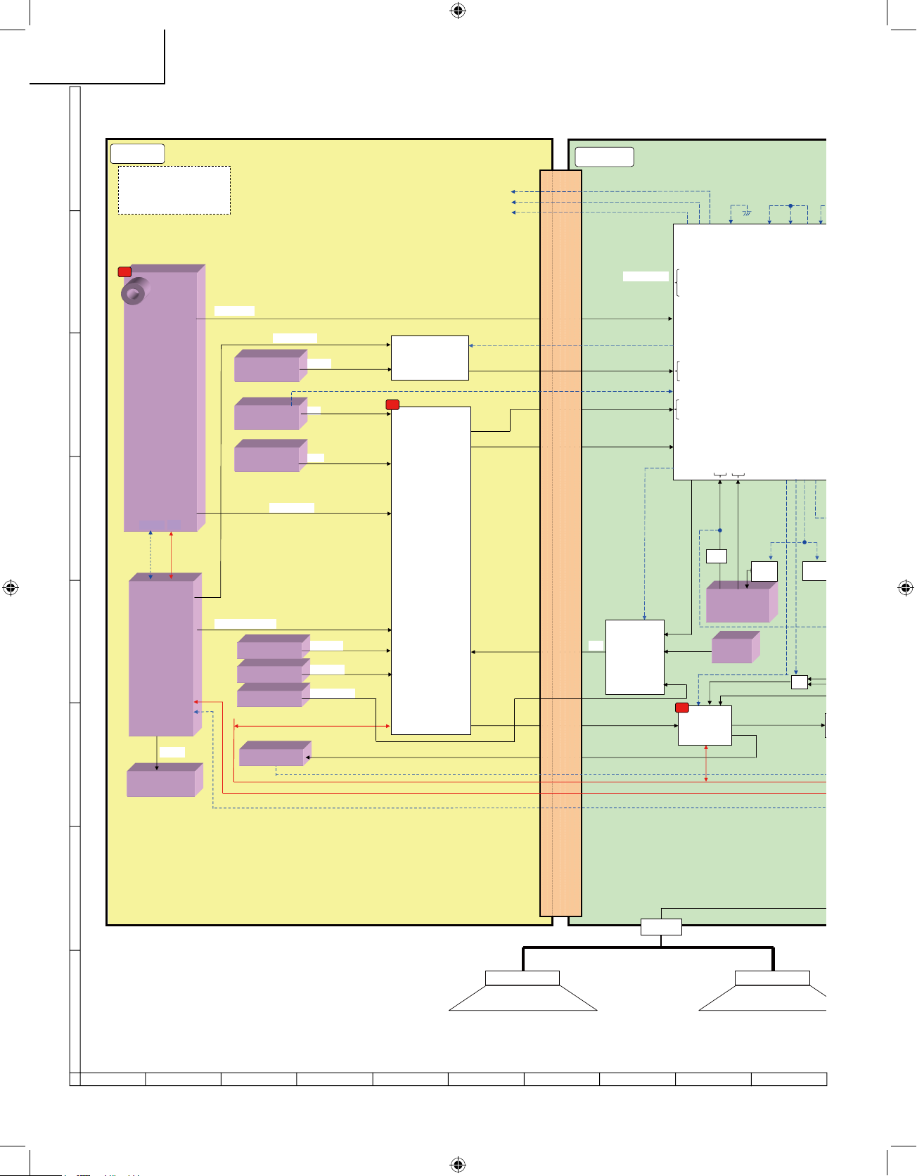
BLOCK DIAGRAM
㪘㪭 㪪㪮
㪠㪚㪌㪇㪊
㪤㪤㪈㪋㪐㪉
㪌 㫀㫅㫇㫌㫋 㪉 㫆㫌㫋㫇㫌㫋
㪍㪻㪙 㪘㪤㪧
㪫㪬㪥㪜㪩
㪫㪬㪈㪈㪇㪈
㪠㪥㪧㪬㪫㪉
㪚㪭㪙㪪 㪠㪥
㪡㪌㪇㪊
㪟㪛㪤㪠 㪘㪬㪛㪠㪦 㪠㪥
㪡㪊㪋㪇㪌
㪠㪥㪧㪬㪫㪈
㪚㪦㪤㪧㪦㪥㪜㪥㪫 㪠㪥
㪡
㪚㪦㪤㪧 㪘㪬㪛㪠㪦 㪠㪥
㪡㪌㪇㪈
㪪㪆㪚㪭㪙㪪 㪘㪬㪛㪠㪦 㪠㪥
㪡㪌㪇㪊
㪠㪥㪧㪬㪫㪉
㪰㪆㪚 㪠㪥
㪡㪌㪇㪊
㪟㪧 㪡㪘㪚㪢
㪡㪌㪇㪌
㪪 㪠㪝
㪚㪭㪙㪪
㪰 㪧㪹 㪧㫉
㪣㪆㪩㪚㪭㪙㪪 㪣㪆㪩
㪚㪦㪤㪧 㪣㪆㪩
㪟㪛㪤㪠 㪜㪯㪫 㪣㪆㪩
㪧㪚 㪣㪆㪩
㪪 㪠㪝 㩿㪘㫅㪸㫃㫀㪾㪀
㪚㪭㪙㪪
㪰㪆㪚
㪰 㪧㪹 㪧㫉
㪘㫌㪻㫀㫆 㪪㪮
㪠㪚
㪤㪤㪉㪎㪌㪇
㪋㫀㫅 㪉㫆㫌㫋
㪣㪆㪩
㪘㫌㪻㫀㫆
㪭㫆㫃㪆㪜㪨㪆㪟㪧㪸㫄㫇
㪠㪚㪊㪇㪈
㪮㪤㪏㪐㪏㪊
㪰㪆㪚
㪰㪧㪹㪧㫉 㪪㪮
㪠㪚㪌㪇㪉
㪫㪣㪌㪉㪇㪌㪌
㪉 㫀㫅㫇㫌㫋 㪈 㫆㫌㫋㫇㫌㫋
㪰 㪧㪹 㪧㫉㩿㪛㫀㪾㫀㫋㪸㫃㪀
㪚㪭㪙㪪 㩿㪘㫅㪸㫃㫆㪾㪀
㪚㪭㪙㪪䇮㪩䇮㪞䇮㪙
㪪㪧㪪㪧
㪣㪆㪩
㪫㪬㪥㪜㪩 㪣㪆㪩 㩿㪛㫀㪾㫀㫋㪸㫃㪀
㪧㪦㪮㪜㪩 㪚㪠㪩㪚㪬㪠㪫
㪠㪉
㪠㪉
㪠㪉
㪪㪪㪮
㪣㪆㪩
㪜㪜㪧㪩㪦㪤
㪙㪩㪉㪋㪚㪉㪈
㪝
㪤㪘㪠㪥
㪪㪬㪙
㪧㪚 㪠㪥
㪪㪚㪋㪇㪈
㪧㪚 㪩㪆㪞㪆㪙
㪪㪛㪘㪪㪚
㪊 㪌㱢㪡㪘㪚㪢
㪟 㪭
㪠㪥㪭㪜㪩㪫
㪠㪚
㪜㪜㪧㪩㪦㪤
㪙㪩㪉㪋㪣㪇㪉㪝
㪠㪚㪋㪇㪈
㪦㪧㪫㪠㪚㪣
㪛㪈㪈㪇㪊
㪪㪆㪧㪛㪠㪝
㪛㪫㪭㪆㪚㪦㪤㪧 㪪㪜㪣
㪛 㪚㪦㪥㪜㪚㪫㪆㪛 㪣㪠㪥㪜㪈㩿㪪㪣㪦㪮㪆㪛 㪣㪠㪥㪜㪉㩿㪝㪙㪀
㪘㪬㪛㪠㪦 㪪㪮㪈㪆㪉
㪤㪧 㪪㪜㪣 㪦㪬㪫
㪪㪧㪛㪠㪝 㪤㪬㪫㪜
㪣㪤㪬㪫㪜
㪛㪫㪭㪆㪫㪬㪥㪜㪩 㪚㪦㪥㪫㪩㪦㪣㪣㩿㪛㪫㪭 㪧㪦㪮䇮㪘㪥㪫 㪧㪦㪮䇮㪛㪫㪭 㪩㪜㪪㪜㪫㪆㪛㪫㪭 㪛 㪘 㪪㪜㪣䇮㪪㪠㪦㩿㪋㪣 㪥㪜㪀䇮㪘㪝㪫㪆㪘㪞㪚 䇮㪛
㪪㪚㪘㪩㪫 㪤㪬㪫㪜
㪮㪧 㪚㪦㪥
㪟㪧
㪪㪩㪜㪪㪜㪫
㪘㪛 㪩
㪤㪧 㪪㪜㪣㪈
㪙㪬㪪㪦㪧㪜㪥
㪤㪧㪪㪜㪣㪇
䌓䌗
㪚㪣㪢 㪪㪜㪣
㪭㪈 㪣㪩
㪭㪉 㪣㪩
㪭㪈 㪭
㪤㪫㪭 㪭
㪪㪫㪭 㪣㪩
㪪㪈
㪪㪉
㪭㪉 㪣㪩
㪤㪫㪭 㪣㪩
㪦㪬㪫㪈 㪣㪩
㪦㪬㪫㪉 㪣㪩
㪭 㪦㪬㪫㪈
㪭 㪦㪬㪫㪉
㪪㪫㪭 㪭
㪟㪛㪤㪠 㪜㪯㪫
㪣㪆㪩
㪛㪫㪭㪆㪚㪦㪤㪧 㪪㪜㪣
㪟䋺㪛㪫㪭
㪣䋺㪚㪦㪤㪧
㪠㪥㪈
㪠㪥㪉
㪠㪥㪊
㪠㪥㪋
#7&+1 59
59 59
/ ^ . ^ .
2% ^ . ^ *
*&/+^ * ^ .
':6 ^ * ^ *
㪙 㪺㪿 㩿㪭㪠㪥㪌㪙㪀
㪘 㪺㪿 㩿㪭㪠㪥㪈㪘㪀 㪞
㪪 㪝
㪘 㪺㪿 㩿㪭㪠㪥㪌㪘㪀 㪙
㪙 㪺㪿 㩿㪭㪠㪥㪈㪙㪀 㪩
㪚 㪺㪿 㩿㪭㪠㪥㪋㪚㪀 㪚㪭㪙㪪
㪚 㪺㪿 㩿㪭㪠㪥㪉㪚㪀 㪰
㪘 㪺㪿 㩿㪭㪠㪥㪊㪘㪀 㪧㪹
㪙 㪺㪿 㩿㪭㪠㪥㪊㪙㪀 㪧㫉
㪘 㪺㪿 㩿㪭㪠㪥㪉㪘㪀 㪚
㪙 㪺㪿 㩿㪭㪠㪥㪉㪙㪀 㪰
㪚 㪺㪿 㩿㪭㪠㪥㪈㪚㪀
㪧㪚㪭㪛㪠㪥
㪧㪚㪟㪛㪠㪥
㪚㪄㪺㪿 㩿㪭㪠㪥㪊㪚㪀 㪔 㪧㪚㪶㪞
㪙㪄㪺㪿 㩿㪭㪠㪥㪋㪙㪀 㪔 㪧㪚㪶
㪩
㪘㪄㪺㪿 㩿㪭㪠㪥㪋㪘㪀 㪔 㪧㪚㪶㪙
㪰㪚 㪦㪬㪫㪈
㪭㪈 㪰㪚
㪤㪧㪜㪞 㪤㪦㪛㪬㪣㪜
㪬㪥㪫㪈㪈㪇㪈
㪠㪉㪚
㪧㪦㪮㪜㪩
19SK24U P58-88.indd 58 2007-8-15 15:31:29
Page 59

59
1716 1918151413121110
LC-19SK24U/U-W
LC-19SB24U/U-W
LC-19SB14U
LC-19D44U
㪠㪥㪭㪜㪩㪫㪜㪩
㪦
㪛㪭㪧 㪤㪉 䋩
㪠㪚㪏㪇㪈
㪩㪟㪄㪠㪯㪙㪏㪏㪉㪮㪡㪱㪱㪨
㪜㪜㪧㪩㪦㪤
㪙㪩㪉㪋㪣㪍㪋㪝
㪠㪚㪏㪇㪊
㪉㪎㪤㪟䌺
㫏㫋㪸㫃
㪠㪚㪉㪇㪇㪉
㪩㪏㪚㪉㪘
㪩㪟㪄㪠㪯㪚㪈㪍㪌㪮㪡㪱㪱㪨
㪩㪜㪪㪜㪫
㪠㪚㪉㪇㪇㪍
㪚㪫㪩㪣㪈
㪚㪦㪥㪫㪩㪦㪣 㪪㪮
㪪㪈㪎㪈 㪪㪈㪎㪌
㪧 㪘
㪥
㪧㪦㪮 㪪㪮
㪪㪈㪎㪎
㪙㪬㪂㪊 㪊㪭
㪢㪜㪰㪈
㪢㪜㪰㪉
㪪㪫㪙㪰 㪧㪦㪮
㪘㪬㪛㪠㪦 㪘㪤㪧
㪛 㪌㪈㪌
㪠㪥㪭㪜㪩㪫㪜㪩
㪛
㪠㪥㪭㪜㪩㪫㪜㪩
㪚㪦㪥㪥㪜㪚㪫㪜㪩
㪈㪋 㪊㪈㪏㪤㪟䌺
㫏㫋㪸㫃
㫧㪊㪇㫇㫇㫄
㪟㪛㪤㪠 㪣㪆㪩 㩿㪠㪉㪪䋩
㪪㪧
㪛
㪧㪦㪮㪜㪩 㪚㪠㪩㪚㪬㪠㪫
㪠㪉
㪛㪭㪧 㪩㪜㪪㪜㪫
㪬㪘㪩㪫
㪚㪜
㪩㪜㪨
㪜㪜㪧 㪪㪫㪦㪧
㪧㪦㪮 㪪㪮
㪣㪜㪛 㪞㪆㪣㪜㪛 㪩㪆㪣㪜㪛 㪦㪧㪚
㪠㪚㪐㪉㪇㪈
㪫㪄㪚㪦㪥
㪩㪪㪛㪪
㪚㪦㪥㪥㪜㪚㪫㪜㪩
㪩㪪㪛㪪
㪚㪦㪥㪥㪜㪚㪫㪜㪩
㪩㪪㪛㪪
㪣㪭㪛㪪
㪩㪪㪛㪪
㪠㪥㪭㪜㪩㪫㪜㪩
㪚㪦㪥㪥㪜㪚㪫㪜㪩
㪟㪛㪤㪠 㪩㪼㪺㫀㪼㫍㪼㫉
㪤㪪㪫㪊㪊㪏㪊㪓㪢 㪣㪝 㪈㪎㪇
㪠㪚㪏㪎㪇㪈
㪊 㪊㪭 㪉㪊㪌㫄㪘
㪉 㪌㪭 㪈㪈㪏㫄㪘
㪩㪞㪙
㪏㪹㫀㫋
㪠㪥㪧㪬㪫㪊
㪟㪛㪤㪠 㪠㪥
㪪㪚㪋㪇㪉
㪜㪜㪧㪩㪦㪤
㪙㪩㪉㪋㪚㪉㪈
㪝
㪪㪛㪘㪪㪚㪣
㪠㪉
㪧㪚 㪩㪆㪞㪆㪙
㪜㪜㪧㪩㪦㪤
㪙㪩㪉㪋㪣㪇㪉㪝
㪠㪚㪋㪇㪈
㪜㪜㪧㪩㪦㪤
㪙㪉㪋㪣㪇㪋㪝
㪠㪚㪉㪇㪇㪊
㪠㪉
㪟㪧 㪛㪜㪫
㪪㪧 㪤㪬㪫㪜
㪟㪧 㪤㪬㪫㪜
㪠㪉㪚㩿㪈㪀
㪪㪛㪘㪈
㪪㪚㪣㪈
㪧㪚 㪟 㪧㪚 㪭
㪠㪉㪚㩿㪇㪀
㪪㪛㪘㪇 㪪㪚㪣㪇
㪧㪉㪇㪇㪊
㪋㫇㫀㫅
㪨㪚㪥㪚㪮㪄㪞㪌㪉㪊㪮㪡㪨㪱
㪠㪩 㪩㪼㪺㫀㪼㫍㪼㫉
㪩㪤㪚㪈㪇㪈
㪣㪜㪛
㪛㪈㪇㪊㪆㪈㪈㪋㪆㪈㪈㪌
㪦㪧㪚
㪠㪚㪈㪇㪈
㪙㪬㪂㪌㪭
㪙㪬㪂㪊 㪊㪭
㪦㪧㪚㪂㪊 㪊㪭
㪩㪆㪚
㪧㪦㪮㪞 㪣㪜㪛
㪧㪦㪮㪩 㪣㪜㪛
㪣㪜㪛 㪦㪧㪚
㪦㪧㪚
㪞㪥㪛
㪧㪈㪇㪈
㪏㫇㫀㫅
㪨㪚㪥㪚㪮㪄㪞㪌㪉㪉㪮㪡㪨㪱
㪢㪜㪰㪈㪆㪉
㪠㪉㪚㩿㪊㪀
㪪㪛㪘㪊
㪪㪚㪣㪊
㪚㪫㪩㪣䋲
㪧㪦㪮㫀㫅
㪛㪭㪧㪈㪌㪠㪥
㪠㪥㪭 㪧㪦㪮
㪣㪘㪤㪧 㪜㪩㪩
㪭㪙㪩㪫
㪧㪚 㪮㪸㫉㫂㪬㪧
㪩㪤㪜
㩿㪩㪆㪚㪀
㪣㪆㪩
㪬㪆㪛
㪧㪘㪥㪜㪣 㪧㪦㪮
㪚㪦㪤 㪙㪠㪘㪪
㪤㪧 㪪㪜㪣 㪦㪬㪫
㪝㪩㪜㪪㪜㪫
㪦㪧㪚
㪮㪧 㪚㪦㪥㪫
㪟㪧㪛㪟㪧㪛㪚㪫㪣
㪤㪬㪫㪜 㪘 㪘㪣㪣
㪪㪪㪫㪙㪰㪘㪤㪧 㪟㪦㪞㪦
㪪㪩㪜㪪㪜㪫
㪘㪛 㪩㪜㪪㪜㪫
㪠㪉㪚㩿㪉㪀 㪪㪛㪘㪉 㪪㪚㪣㪉
㪠㪉㪪
㪩㪩㪈㪯㪚
㪆㪇㪆㪈㪆㪉 㪆㪂
㪀㪈㩿㪚㪉㪠㪀㪊㩿㪚㪉㪠㪀㪉㩿㪚㪉㪠
㪤㪧 㪪㪜㪣㪈
㪙㪬㪪㪦㪧㪜㪥
㪫㪬㪌㪭 㪛㪜㪫
㪘㪚 㪚㪫㪣
㪠㪚㪊㪇㪌
㪦㪪㪚
䌓䌗
㪚㪣㪢 㪪㪜㪣
㪎㪤 㪉㪇䌍䌈䌺
㪘㪄㪺㪿 㩿㪭㪠㪥㪋㪘㪀 㪔 㪧㪚㪶㪙
19SK24U P58-88.indd 59 2007-8-15 15:31:34
Page 60

60
87 109654321
A
B
C
D
E
F
G
H
LC-19SK24U/U-W
LC-19SB24U/U-W
LC-19SB14U
LC-19D44U
OVERALL WIRING DIAGRAM
19SK24U P58-88.indd 60 2007-8-15 15:31:42
Page 61

61
1716 1918151413121110
LC-19SK24U/U-W
LC-19SB24U/U-W
LC-19SB14U
LC-19D44U
19SK24U P58-88.indd 61 2007-8-15 15:31:48
Page 62

62
LC-19SK24U/U-W
LC-19SB24U/U-W
LC-19SB14U
LC-19D44U
VOLTAGE MEASUREMENT CONDITION:
1. The voltages at test points are measured on the
stable supply voltage of AC 120V. Signals are
fed by a color bar signal generator for servicing
purpose and the above voltages are measured
with a 20k ohm/V tester.
INDICATION OF RESISTOR & CAPACITOR:
RESISTOR
1. The unit of resistance “Ω” is omitted.
(K=kΩ=1000 Ω, M=MΩ).
2. All resistors are ± 5%, unless otherwise noted.
(K= ± 10%, F= ± 1%, D= ± 0.5%)
3. All resistors are 1/16W, unless otherwise noted.
CAPACITOR
1. All capacitors are µF
, unless otherwise noted.
(P=pF=µµF).
2.
All capacitors are 50V, unless otherwise noted.
CAUTION:
This circuit diagram is original one, therefore there may be a
slight difference from yours.
SAFETY NOTES:
1. DISCONNECT THE AC PLUG FROM THE AC
OUTLET BEFORE REPLACING PARTS.
2. SEMICONDUCTOR HEAT SINKS SHOULD BE
REGARDED AS POTENTIAL SHOCK HAZARDS WHEN THE CHASSIS IS OPERATING.
IMPORTANT SAFETY NOTICE:
PARTS MARKED WITH “Α”
( ) AR E
IMPORTANT FOR MAINTAINING THE SAFETY OF
THE SET. BE SURE TO REPLACE THESE PARTS
WITH SPECIFIED ONES FOR MAINTAINING THE
SAFETY AND PERFORMANCE OF THE SET.
AVIS DE SECURITE IMPORTANT:
LES PIECES MARQUEES “Α” ( )SONT
IMPORTANTES POUR MAINTENIR LA SECURITE
DE L'APPAREIL.
NE REMPLACER CES PIEDES QUE PAR DES
PIECES DONT LE NUMERO EST SPECIFIE POUR
MAINTENIR LA SECURITE ET PROTEGER LE
BON FONCTIONNEMENT DE L'APPAREIL.
DESCRIPTION OF SCHEMATIC DIAGRAM
19SK24U P58-88.indd 62 2007-9-13 10:34:36
Page 63

63
87 109654321
A
B
C
D
E
F
G
H
LC-19SK24U/U-W
LC-19SB24U/U-W
LC-19SB14U
LC-19D44U
SCHEMATIC DIAGRAM
R/C LED Unit
19SK24U P58-88.indd 63 2007-8-15 15:31:53
Page 64

64
87 109654321
A
B
C
D
E
F
G
H
LC-19SK24U/U-W
LC-19SB24U/U-W
LC-19SB14U
LC-19D44U
MAIN Unit - 1/9
19SK24U P58-88.indd 64 2007-8-15 15:32:06
Page 65

65
1716 1918151413121110
LC-19SK24U/U-W
LC-19SB24U/U-W
LC-19SB14U
LC-19D44U
19SK24U P58-88.indd 65 2007-8-15 15:32:19
Page 66

66
87 109654321
A
B
C
D
E
F
G
H
LC-19SK24U/U-W
LC-19SB24U/U-W
LC-19SB14U
LC-19D44U
MAIN Unit - 2/9
19SK24U P58-88.indd 66 2007-8-15 15:32:28
Page 67

67
1716 1918151413121110
LC-19SK24U/U-W
LC-19SB24U/U-W
LC-19SB14U
LC-19D44U
19SK24U P58-88.indd 67 2007-8-15 15:32:32
Page 68

68
87 109654321
A
B
C
D
E
F
G
H
LC-19SK24U/U-W
LC-19SB24U/U-W
LC-19SB14U
LC-19D44U
MAIN Unit - 3/9
19SK24U P58-88.indd 68 2007-8-15 15:32:38
Page 69

69
1716 1918151413121110
LC-19SK24U/U-W
LC-19SB24U/U-W
LC-19SB14U
LC-19D44U
19SK24U P58-88.indd 69 2007-8-15 15:32:44
Page 70

70
87 109654321
A
B
C
D
E
F
G
H
LC-19SK24U/U-W
LC-19SB24U/U-W
LC-19SB14U
LC-19D44U
MAIN Unit - 4/9
19SK24U P58-88.indd 70 2007-8-15 15:32:50
Page 71
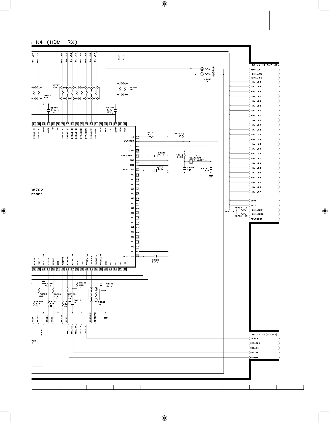
71
1716 1918151413121110
LC-19SK24U/U-W
LC-19SB24U/U-W
LC-19SB14U
LC-19D44U
19SK24U P58-88.indd 71 2007-8-15 15:32:55
Page 72

72
87 109654321
A
B
C
D
E
F
G
H
LC-19SK24U/U-W
LC-19SB24U/U-W
LC-19SB14U
LC-19D44U
MAIN Unit - 5/9
19SK24U P58-88.indd 72 2007-8-15 15:33:00
Page 73

73
1716 1918151413121110
LC-19SK24U/U-W
LC-19SB24U/U-W
LC-19SB14U
LC-19D44U
19SK24U P58-88.indd 73 2007-8-15 15:33:02
Page 74

74
87 109654321
A
B
C
D
E
F
G
H
LC-19SK24U/U-W
LC-19SB24U/U-W
LC-19SB14U
LC-19D44U
MAIN Unit - 6/9
19SK24U P58-88.indd 74 2007-8-15 15:33:07
Page 75

75
1716 1918151413121110
LC-19SK24U/U-W
LC-19SB24U/U-W
LC-19SB14U
LC-19D44U
19SK24U P58-88.indd 75 2007-8-15 15:33:10
Page 76

76
87 109654321
A
B
C
D
E
F
G
H
LC-19SK24U/U-W
LC-19SB24U/U-W
LC-19SB14U
LC-19D44U
MAIN Unit - 7/9
19SK24U P58-88.indd 76 2007-8-15 15:33:13
Page 77

77
1716 1918151413121110
LC-19SK24U/U-W
LC-19SB24U/U-W
LC-19SB14U
LC-19D44U
19SK24U P58-88.indd 77 2007-8-15 15:33:14
Page 78

78
87 109654321
A
B
C
D
E
F
G
H
LC-19SK24U/U-W
LC-19SB24U/U-W
LC-19SB14U
LC-19D44U
MAIN Unit - 8/9
19SK24U P58-88.indd 78 2007-8-15 15:33:19
Page 79

79
1716 1918151413121110
LC-19SK24U/U-W
LC-19SB24U/U-W
LC-19SB14U
LC-19D44U
19SK24U P58-88.indd 79 2007-8-15 15:33:24
Page 80

80
87 109654321
A
B
C
D
E
F
G
H
LC-19SK24U/U-W
LC-19SB24U/U-W
LC-19SB14U
LC-19D44U
MAIN Unit - 9/9
19SK24U P58-88.indd 80 2007-8-15 15:33:29
Page 81

81
1716 1918151413121110
LC-19SK24U/U-W
LC-19SB24U/U-W
LC-19SB14U
LC-19D44U
19SK24U P58-88.indd 81 2007-8-15 15:33:33
Page 82

82
87 109654321
A
B
C
D
E
F
G
H
LC-19SK24U/U-W
LC-19SB24U/U-W
LC-19SB14U
LC-19D44U
SUB Unit - 1/2
19SK24U P58-88.indd 82 2007-8-15 15:33:37
Page 83

83
1716 1918151413121110
LC-19SK24U/U-W
LC-19SB24U/U-W
LC-19SB14U
LC-19D44U
19SK24U P58-88.indd 83 2007-8-15 15:33:41
Page 84

84
87 109654321
A
B
C
D
E
F
G
H
LC-19SK24U/U-W
LC-19SB24U/U-W
LC-19SB14U
LC-19D44U
SUB Unit - 2/2
19SK24U P58-88.indd 84 2007-8-15 15:33:47
Page 85

85
1716 1918151413121110
LC-19SK24U/U-W
LC-19SB24U/U-W
LC-19SB14U
LC-19D44U
19SK24U P58-88.indd 85 2007-8-15 15:33:53
Page 86

86
87 109654321
A
B
C
D
E
F
G
H
LC-19SK24U/U-W
LC-19SB24U/U-W
LC-19SB14U
LC-19D44U
POWER_INVERTER Unit
19SK24U P58-88.indd 86 2007-8-15 15:34:00
Page 87

87
1716 1918151413121110
LC-19SK24U/U-W
LC-19SB24U/U-W
LC-19SB14U
LC-19D44U
19SK24U P58-88.indd 87 2007-8-15 15:34:06
Page 88

88
87 109654321
A
B
C
D
E
F
G
H
LC-19SK24U/U-W
LC-19SB24U/U-W
LC-19SB14U
LC-19D44U
KEY Unit
19SK24U P58-88.indd 88 2007-8-15 15:34:10
Page 89

89
LC-19SK24U/U-W
LC-19SB24U/U-W
LC-19SB14U
LC-19D44U
87 109654321
A
B
C
D
E
F
G
H
PRINTED WIRING BOARD ASSEMBLIES
SW Unit (Side-A)
SW Unit (Chip Part Side-A)
SW Unit (Side-B)
SW Unit (Chip PartSide-B)
19SK24U P89-108.indd 89 2007-9-3 16:04:23
Page 90

90
LC-19SK24U/U-W
LC-19SB24U/U-W
LC-19SB14U
LC-19D44U
87 109654321
A
B
C
D
E
F
G
H
MAIN Unit (Side-A)
19SK24U P89-108.indd 90 2007-8-15 15:43:13
Page 91

91
LC-19SK24U/U-W
LC-19SB24U/U-W
LC-19SB14U
LC-19D44U
1716 1918151413121110
19SK24U P89-108.indd 91 2007-8-15 15:43:21
Page 92

92
LC-19SK24U/U-W
LC-19SB24U/U-W
LC-19SB14U
LC-19D44U
87 109654321
A
B
C
D
E
F
G
H
MAIN Unit (Chip Parts Side-A)
19SK24U P89-108.indd 92 2007-8-15 15:43:29
Page 93

93
LC-19SK24U/U-W
LC-19SB24U/U-W
LC-19SB14U
LC-19D44U
1716 1918151413121110
19SK24U P89-108.indd 93 2007-8-15 15:43:34
Page 94

94
LC-19SK24U/U-W
LC-19SB24U/U-W
LC-19SB14U
LC-19D44U
87 109654321
A
B
C
D
E
F
G
H
MAIN Unit (Side-B)
19SK24U P89-108.indd 94 2007-8-15 15:43:44
Page 95

95
LC-19SK24U/U-W
LC-19SB24U/U-W
LC-19SB14U
LC-19D44U
1716 1918151413121110
19SK24U P89-108.indd 95 2007-8-15 15:43:53
Page 96

96
LC-19SK24U/U-W
LC-19SB24U/U-W
LC-19SB14U
LC-19D44U
87 109654321
A
B
C
D
E
F
G
H
MAIN Unit (Chip Parts Side-B)
19SK24U P89-108.indd 96 2007-9-3 16:05:41
Page 97

97
LC-19SK24U/U-W
LC-19SB24U/U-W
LC-19SB14U
LC-19D44U
1716 1918151413121110
19SK24U P89-108.indd 97 2007-9-3 16:05:45
Page 98

98
LC-19SK24U/U-W
LC-19SB24U/U-W
LC-19SB14U
LC-19D44U
87 109654321
A
B
C
D
E
F
G
H
SUB Unit (Side-A)
19SK24U P89-108.indd 98 2007-8-15 15:44:10
Page 99

99
LC-19SK24U/U-W
LC-19SB24U/U-W
LC-19SB14U
LC-19D44U
1716 1918151413121110
19SK24U P89-108.indd 99 2007-8-15 15:44:11
Page 100

100
LC-19SK24U/U-W
LC-19SB24U/U-W
LC-19SB14U
LC-19D44U
87 109654321
A
B
C
D
E
F
G
H
SUB Unit (Side-B)
19SK24U P89-108.indd 100 2007-8-15 15:44:17
 Loading...