

Page 1
LC-15PX1U
SERVICE MANUAL
S15D4LC15PX1U
LCD COLOR TELEVISION
MODEL
In the interests of user-safety (Required by safety regulations in some countries) the set should be restored
to its original condition and only parts identical to those specified should be used.
CONTENTS
» IMPORT ANT SER VICE SAFETY PRECAUTION.........................................................................................2
» SPECIFICATIONS ........................................................................................................................................5
» OPERATION MANUAL ............................................................................................................... ..................6
» DIMENSIONS ...............................................................................................................................................8
» REMOVING OF MAJOR P ARTS ..................................................................................................................9
» ADJUSTING PROCEDURE OF EACH SECTION .....................................................................................14
» TROUBLE SHOOTING TABLE ..................................................................................................................20
» CHASSIS LAYOUT .....................................................................................................................................26
» BLOCK DIAGRAM......................................................................................................................................28
» OVERALL WIRING DIAGRAM ...................................................................................................................30
» DESCRIPTION OF SCHEMATIC DIAGRAM .............................................................................................32
» SCHEMATIC DIAGRAM .............................................................................................................................33
» PRINTED WIRING BOARD ASSEMBLIES................................................................................................74
» REPLACEMENT PARTS LIST.................................................................................................................... 85
» PACKING OF THE SET............................................................................................................................103
LC-15PX1U
Page
SHARP CORPORATION
This document has been published to be used for
after sales service only.
The contents are subject to change without notice.
Page 2
LC-15PX1U
2
3
3
IMPORTANT SERVICE SAFETY PRECAUTION
Ë
Service work should be performed only by qualified service technicians who are thoroughly familiar with all safety checks and the servicing guidelines which follow:
WARNING
1. For continued safety, no modification of any circuit
should be attempted.
2. Disconnect AC power before servicing.
CAUTION: FOR CONTINUED
PROTECTION AGAINST A RISK OF
FIRE REPLACE ONLY WITH SAME
TYPE F3701 (2.5A, 250V), F3702
A V
(2.5A, 250V), F6501(1.25A, 250V)
AND F6502 (1.25A, 250V) FUSE.
BEFORE RETURNING THE RECEIVER
(Fire & Shock Hazard)
Before returning the receiver to the user, perform
the following safety checks:
1. Inspect all lead dress to make certain that leads are
not pinched, and check that hardware is not lodged
between the chassis and other metal parts in the
receiver.
2. Inspect all protective devices such as non-metallic
control knobs, insulation materials, cabinet backs,
adjustment and compartment covers or shields, isolation
resistor-capacitor networks, mechanical insulators, etc.
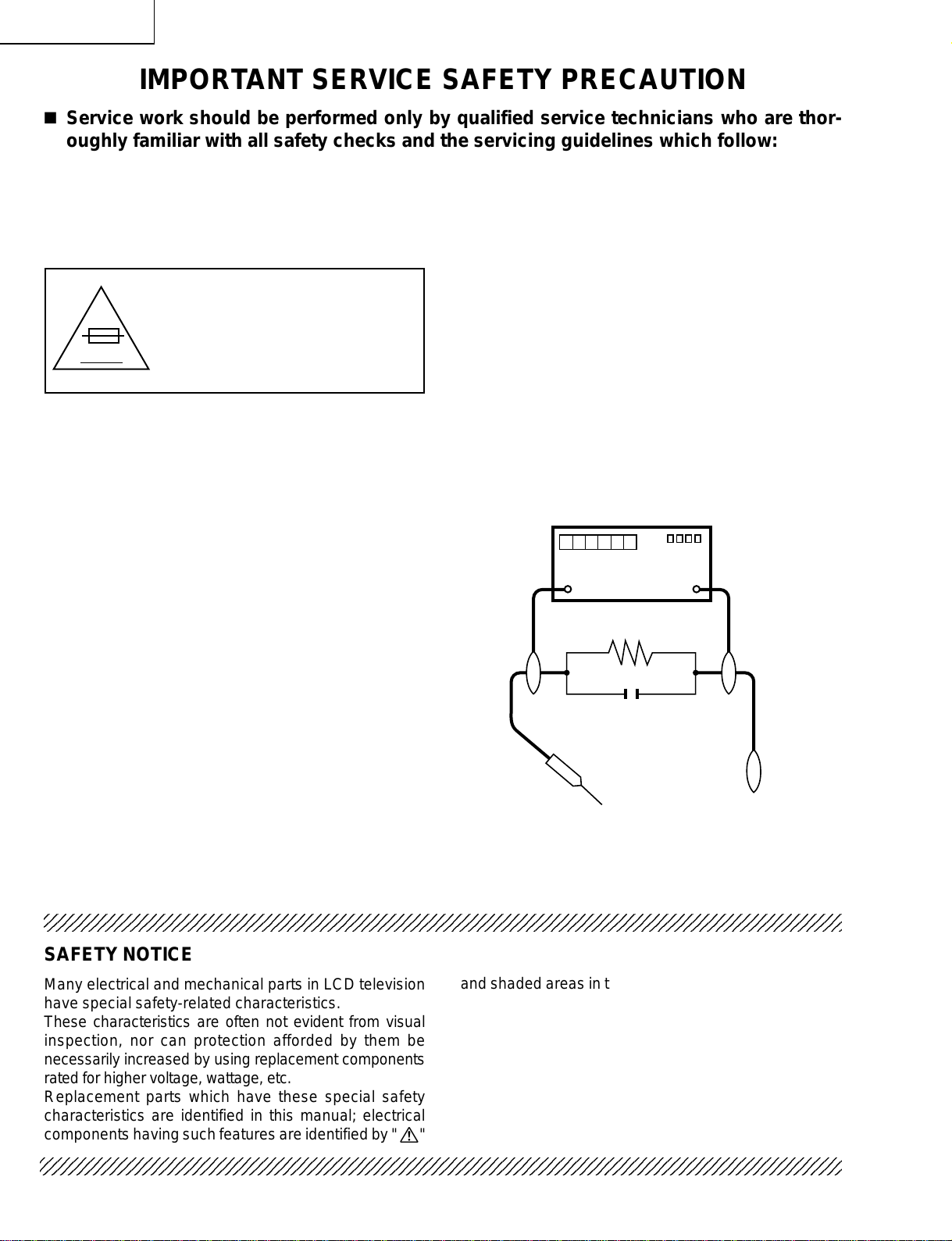
3. To be sure that no shock hazard exists, check for
leakage current in the following manner.
• Plug the AC cord directly into a 110~240 volt AC outlet,
and connect the DC power cable into the receiver's DC
jack. (Do not use an isolation transformer for this test).
• Using two clip leads, connect a 1.5k ohm, 10 watt
resistor paralleled by a 0.15µF capacitor in series with
all exposed metal cabinet parts and a known earth
ground, such as electrical conduit or electrical ground
connected to an earth ground.
• Use an AC voltmeter having with 5000 ohm per volt, or
higher, sensitivity or measure the AC voltage drop
across the resistor.
• Connect the resistor connection to all exposed metal
parts having a return to the chassis (antenna, metal
cabinet, screw heads, knobs and control shafts,
escutcheon, etc.) and measure the AC voltage drop
across the resistor.
All checks must be repeated with the AC cord plug
connection reversed. (If necessary, a nonpolarized
adaptor plug must be used only for the purpose of
completing these checks.)
Any reading of 0.75V peak (this corresponds to 0.5 mA.
peak AC.) or more is excessive and indicates a potential
shock hazard which must be corrected before returning
the monitor to the owner.
DVM
AC SCALE
1.5k ohm
10W
0.15 µF
TEST PROBE
TO EXPOSED
METAL PARTS
CONNECT TO
KNOWN EARTH
GROUND
234567890123456789012345678901212345678901234567890123456789012123456789012345678901234567890121
SAFETY NOTICE
Many electrical and mechanical parts in LCD television
have special safety-related characteristics.
These characteristics are often not evident from visual
inspection, nor can protection afforded by them be
necessarily increased by using replacement components
rated for higher voltage, wattage, etc.
Replacement parts which have these special safety
characteristics are identified in this manual; electrical
and shaded areas in the
Schematic Diagrams
For continued protection, replacement parts must be
identical to those used in the original circuit.
The use of a substitute replacement parts which do not
have the same safety characteristics as the factory
recommended replacement parts shown in this service
manual, may create shock, fire or other hazards.
components having such features are identified by " å"
2345678901234567890123456789012123456789012345678901234567890121234567890123456789012345678901212
2345678901234567890123456789012123456789012345678901234567890121234567890123456789012345678901212
2
Replacement Parts Lists
.
and
Page 3
LC-15PX1U
2
2
2
PRECAUTIONS A PRENDRE LORS DE LA REPARATION
Ë
Ne peut effectuer la réparation qu' un technicien spécialisé qui s'est parfaitement
accoutumé à toute vérification de sécurité et aux conseils suivants.
AVERTISSEMENT
1. N'entreprendre aucune modification de tout circuit.
C'est dangereux.
2. Débrancher le récepteur avant toute réparation.
PRECAUTION: POUR LA
PROTECTION CONTINUE
CONTRE LES RISQUES
D'INCENDIE, REMPLACER LE
FUSIBLE PAR UN FUSIBLE DE
A V
MEME TYPE F3701 (2.5A, 250V),
F3702 (2.5A, 250V), F6501 (1.25A,
250V), F6502 (1.25A, 250V).
VERIFICATIONS CONTRE L'INCEN-DIE ET
LE CHOC ELECTRIQUE
Avant de rendre le récepteur à l'utilisateur, effectuer
les vérifications suivantes.
1. Inspecter tous les faisceaux de câbles pour s'assurer
que les fils ne soient pas pincés ou qu'un outil ne soit
pas placé entre le châssis et les autres pièces
métalliques du récepteur.
2. Inspecter tous les dispositifs de protection comme les
boutons de commande non-métalliques, les isolants,
le dos du coffret, les couvercles ou blindages de réglage
et de compartiment, les réseaux de résistance-capacité,
les isolateurs mécaniques, etc.
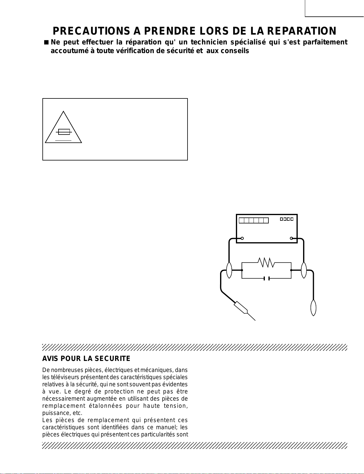
3. S'assurer qu'il n'y ait pas de danger d'électrocution en
vérifiant la fuite de courant, de la facon suivante:
• Brancher le cordon d'alimentation directem-ent à une
prise de courant de 110-240V. (Ne pas utiliser de
transformateur d'isolation pour cet essai).
• A l'aide de deux fils à pinces, brancher une résistance
de 1.5kΩ 10 watts en parallèle avec un condensateur
de 0.15µF en série avec toutes les pièces métalliques
exposées du coffret et une terre connue comme une
conduite électrique ou une prise de terre branchée à la
terre.
• Utiliser un voltmètre CA d'une sensibilité d'au moins
5000Ω/V pour mesurer la chute de tension en travers
de la résistance.
• Toucher avec la sonde d'essai les pièces métalliques
exposées qui présentent une voie de retour au châssis
(antenne, coffret métallique, tête des vis, arbres de
commande et des boutons, écusson, etc.) et mesurer
la chute de tension CA en-travers de la résistance.
T outes les vérifications doivent être refaites après avoir
inversé la fiche du cordon d'alimentation. (Si nécessaire,
une prise d'adpatation non polarisée peut être utilisée
dans le but de terminer ces vérifications.)
Tous les courants mesurés ne doivent pas dépasser
0,5 mA.
Dans le cas contraire, il y a une possibilité de choc
électrique qui doit être supprimée avant de rendre le
récepteur au client.
DVM
ECHELLE CA
1.5k ohm
10W
0.15 µF
SONDE D'ESSAI
AUX PIECES
METALLIQUES
EXPOSEES
BRANCHER A UNE
TERRE CONNUE
234567890123456789012345678901212345678901234567890123456789012123456789012345678901234567890121
AVIS POUR LA SECURITE
De nombreuses pièces, électriques et mécaniques, dans
les téléviseurs présentent des caractéristiques spéciales
relatives à la sécurité, qui ne sont souvent pas évidentes
à vue. Le degré de protection ne peut pas être
nécessairement augmentée en utilisant des pièces de
remplacement étalonnées pour haute tension,
puissance, etc.
Les pièces de remplacement qui présentent ces
caractéristiques sont identifiées dans ce manuel; les
pièces électriques qui présentent ces particularités sont
234567890123456789012345678901212345678901234567890123456789012123456789012345678901234567890121
234567890123456789012345678901212345678901234567890123456789012123456789012345678901234567890121
identifiées par la marque " å " et hachurées dans la
liste des pièces de remplacement et les diagrammes
schématiques.
Pour assurer la protection, ces pièces doivent être
identiques à celles utilisées dans le circuit d'origine.
L'utilisation de pièces qui n'ont pas les mêmes
caractéristiques que les pièces recommandées par
l'usine, indiquées dans ce manuel, peut provoquer des
électrocutions, incendies, radiations X ou autres
accidents.
3
Page 4
LC-15PX1U
Precautions for using lead-free solder
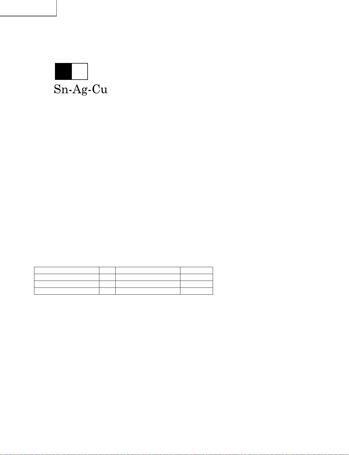
1 Employing lead-free solder
"All PWBs" of this model employs lead-free solder. The LF symbol indicates lead-free solder, and is attached on
the PWBs and service manuals. The alphabetical character following LF shows the type of lead-free solder.
Example:
L Fa
Indicates lead-free solder of tin, silver and copper.
2 Using lead-free wire solder
When fixing the PWB soldered with the lead-free solder, apply lead-free wire solder. Repairing with conventional
lead wire solder may cause damage or accident due to cracks.
As the melting point of lead-free solder (Sn-Ag-Cu) is higher than the lead wire solder by 40°C, we recommend
you to use a dedicated soldering bit, if you are not familiar with how to obtain lead-free wire solder or soldering bit,
contact our service station or service branch in your area.
3 Soldering
As the melting point of lead-free solder (Sn-Ag-Cu) is about 220°C which is higher than the conventional lead
solder by 40°C, and as it has poor solder wettability, you may be apt to keep the soldering bit in contact with the
PWB for extended period of time. However, Since the land may be peeled off or the maximum heat-resistance
temperature of parts may be exceeded, remove the bit from the PWB as soon as you confirm the steady soldering
condition.
Lead-free solder contains more tin, and the end of the soldering bit may be easily corroded. Make sure to turn on
and off the power of the bit as required.
If a different type of solder stays on the tip of the soldering bit, it is alloyed with lead-free solder . Clean the bit after
every use of it.
When the tip of the soldering bit is blackened during use, file it with steel wool or fine sandpaper.
Be careful when replacing parts with polarity indication on the PWB silk.
Lead-free wire solder for servicing
Part No, ★ Description Code
ZHNDAi123250E J φ0.3mm 250g(1roll) BL
ZHNDAi126500E J φ0.6mm 500g(1roll) BK
ZHNDAi12801KE J φ1.0mm 1kg(1roll) BM
4
Page 5
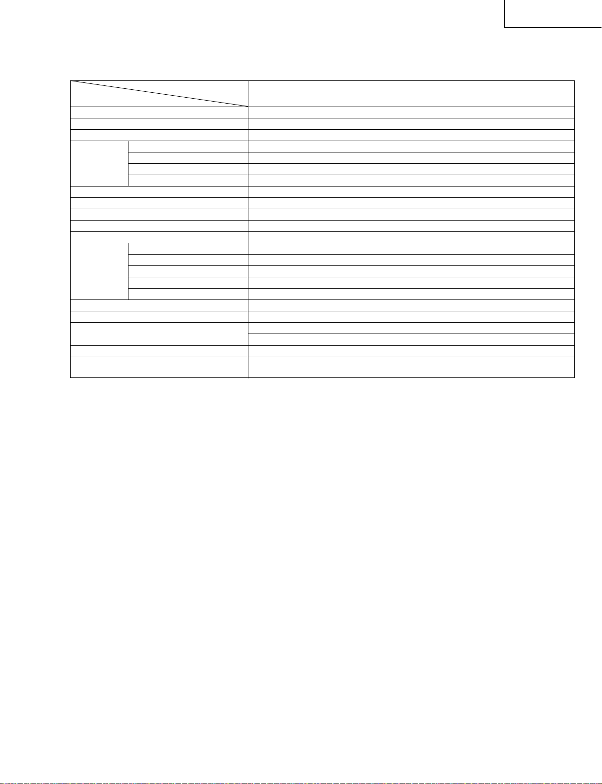
SPECIFICATIONS
Items LC-15PX1U
LCD panel
15" Advanced Super View & BLACK TFT LCD
Number of dots 921,600 dots XGA
Video color systems N358
TV Standard (CCIR) NTSC
TV function
TV Tuning System PLL 181 ch.
STEREO MTS+SAP
CATV 125 ch.
Y/C FILTER DIGITAL COMB FILTER
Brightness 430 cd/m
2
Viewing angles H: 170° V: 170°
Audio amplifier 2.1 W 2
Speakers 137/64 249/64 in. (4.0 7.0 cm), 2 pcs.
COMPONENT COMPONENT-IN, AUDIO-IN
AV-IN1 AV-IN1, AUDIO-IN, S-VIDEO-IN
Terminals AV-IN2/OUT AV-IN2/AV-OUT, AUDIO-IN/OUT
Antenna F-Type
Headphone Mini-jack for stereo (ø3.5 mm)
OSD language English/Spanish/French
Power supply DC 12V, AC 110-240V, 50/60Hz (AC adapter), AC 110-125V (AC cord)
Power consumption 49 W (0.4 W standby): AC 120V
40 W: DC 12V
Weight 12.6 lbs. (5.7 kg), w/o accessories
Accessories Remote control, Battery ( 2), Antenna cable, AC adapter, AC cord, Cable holder,
Operation manual
ËAs a part of policy of continuous improvement, SHARP reserves the right to make design and specification changes for product improve-
ment without prior notice. The performance specification figures indicated are nominal values of production units. There may be some
deviations from these values in individual units.
Model
×
××
×
LC-15PX1U
5
Page 6
LC-15PX1U
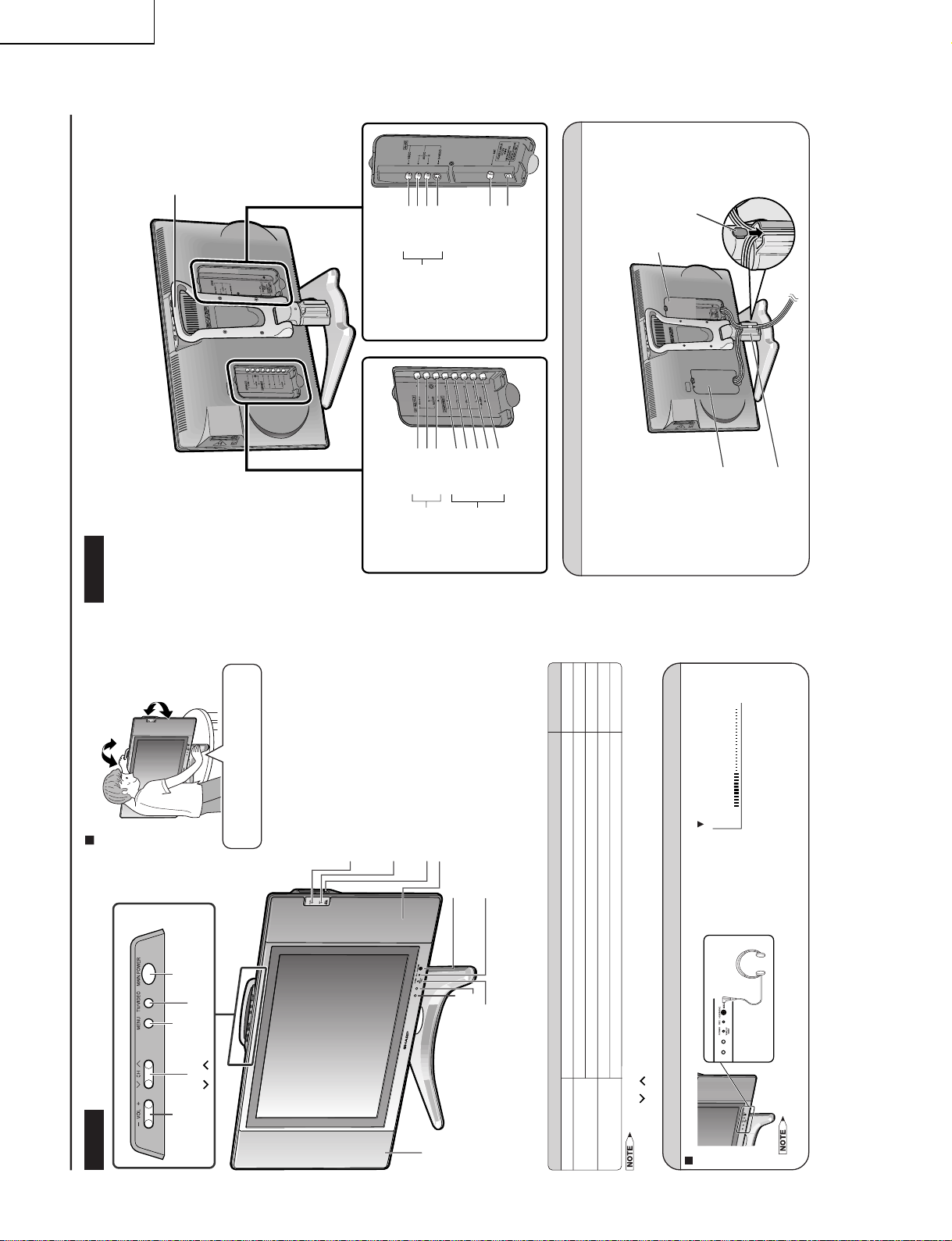
Speaker
HEADPHONE jack
Plug the headphone mini-plug into the Headphone
jack located on the front of the main unit.
CARD lamp
The CARD lamp lights up depending on the
usage status of the card. For details, see Status
of the CARD lamp below.
PC card slot × 2
OPC (Optical Picture Control) indicator
The OPC indicator lights up green when the “OPC” is
set to “ON”.
Remote sensor
OPC (Optical Picture Control) sensor
Speaker
MIC
Microphone used for the Audio Message Board
function.
POWER/WAKE UP TIMER indicator
POWER indicator lights up green when the power is on, and red
when in the standby mode (the indicator will not light when the main
power is off), and orange when the Wak e Alarm is set (the indicator
will light when in the standby mode).
Part Names of the Main Unit
Controls
Status of the CARD lamp
• TV/VIDEO, CH (
)/(
), VOL (–)/(+) and MENU on the main unit have the same functions as the same buttons on the remote control.
Fundamentally, this operation manual provides a description based on operation using the remote control.
To change the vertical angle of the LCD TV
set, tilt the screen up to 5 degrees forward or
10 degrees backward. The display can also
be rotated up to 25 degrees to right and left.
When tilting or rotating the display, be sure
to securely hold down the stand.
Please adjust the angle so that the display
can be watched most comfortably.
MAIN POWER
Upper control panel
TV/VIDEO
MENU
CH (Channel)
(
)/( )
VOL (Volume)
(–)/(+)
Tilt the display by grabbing onto the
carrying handle while securely holding
down the stand with your hand.
How to adjust the angle
Listening with Headphones
Plug the headphone mini-plug into the HEADPHONE jack located on the front of the main unit.
On-screen display
20
VOLUME
Adjust the sound volume
using VOL (
+
)/(
–
) on the
remote control.
Headphones
• Headphones are not included in the supplied accessories.
• No sound is heard from the main unit speakers when a headphone mini-plug is connected into the HEADPHONE jack.
Status of the LCD TV set Lamp
On or on standby When a card is not inserted in the PC card slot Off
On
When the card in the PC card slot is accessed Red
When the card in the PC card slot is not accessed Green
On standby
When timer-recording is set Orange
When there are audio messages that have yet to be listened Blinking red
Terminals
Carrying handle
Rear View
Y
P
B
P
R
AUDIO (L)
AUDIO (R)
VIDEO
AUDIO (R)
AUDIO (L)
AV-IN2/OUT
ANT. (Antenna terminal)
POWER INPUT
(DC 12V)
VIDEO
AUDIO (L)
AUDIO (R)
S-VIDEO
AV-IN1
COMPONENT
How to Fix the Cables
• Pull the cables connected to each terminal through the holes and close the left and right terminal covers.
Push the cables into the grooves of the support covers. Insert the cable holder (supplied) from above the
support cover and fix the cables.
Cable holder
Terminal cover
Support cover
Terminal cover
OPERATION MANUAL
6
Page 7
LC-15PX1U
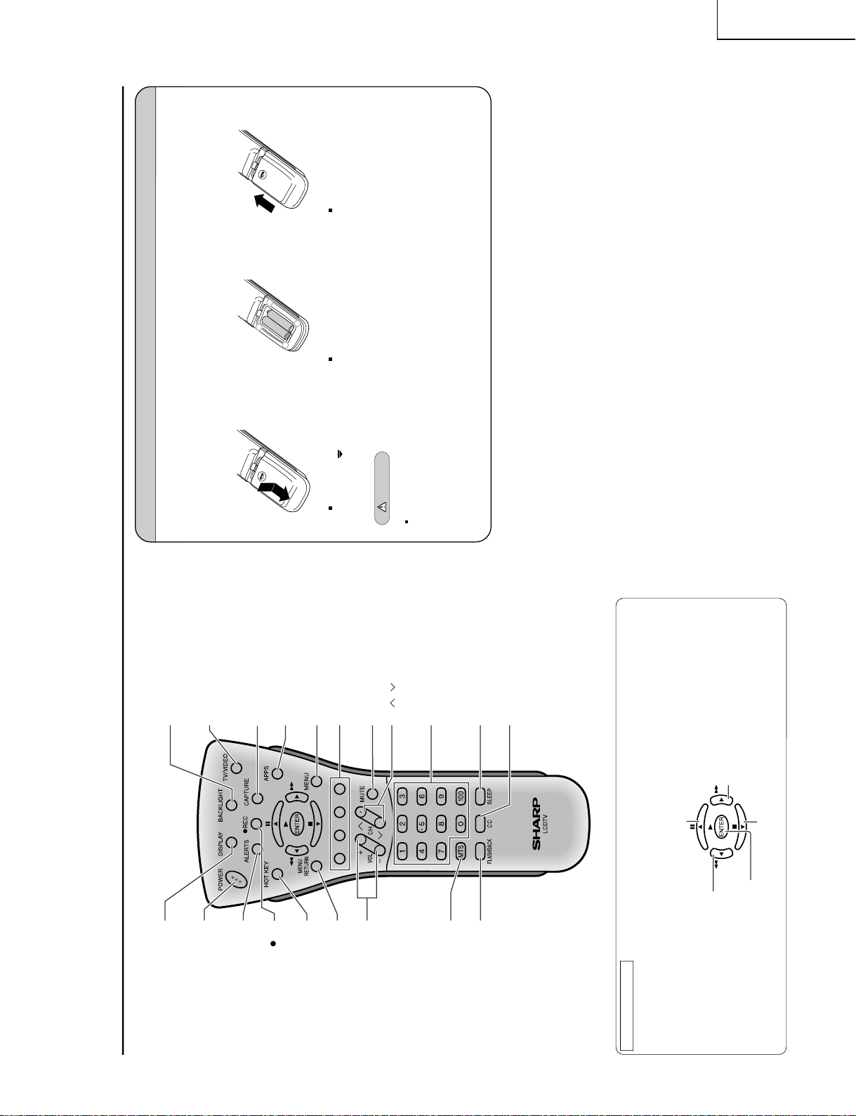
Part Names of the Remote Control
POWER
Turns the Liquid Crystal
Television power on or off.
ALERTS
Displays the Alerts Manager screen.
HOT KEY
Displays the Hotkey Manager screen.
MENU RETURN
Returns to the previous screen.
VOL (+)/(–)
Sets the volume.
MTS
Selects audio settings.
FLASHBACK
Returns to the previous channel.
REC
Records the motion picture.
DISPLAY
Displays the receiving channel and
the current time for 10 seconds.
CAPTURE
Records the still picture.
TV/VIDEO
Switches the input source between
AV1, AV2, COMPONENT
and TV mode.
MENU
Displays the menu screen.
MUTE
Mutes the sound.
CC
Displays Closed Caption subtitles.
Color Buttons
Directly runs the application
assigned by Hotkey Manager function.
Channel Select
Selects the channel.
SLEEP
Sets the sleep timer.
APPS
Displays the Application Manager
screen.
BACKLIGHT
Selects the brightness and
OPC of the screen.
CH ( )/( )
Selects the channel.
Move the cursor upwards
(Select the menu items)
/
Still
(Pause the live TV, playback or recording)
Move the cursor to the right
(Select the menu items)
/
Fast-forward
(Fast-forward the picture)
Move the cursor downwards
(Select the menu items)
/
Stop
(Stop the playback or recording)
ENTER
(Set the menu or items by selecting the cursor)
/
Play
(Start the playback)
Move the cursor to the left
(Select the menu items)
/
Fast-reverse
(Fast-reverse the picture)
How to use the cursor
The cursor is used when:
Selecting a menu in the on-screen display
•
•
Operating PVR functions and Video Player application
Installing Batteries in the Remote Control
Before using the LCD TV set for the first time, install the two
“AAA” size batteries supplied in the remote control. When the
batteries become depleted and the remote control fails to operate, replace the batteries with new
“AAA” size batteries.
1
Open the battery cover.
2
Insert two “AAA” size batteries.
3
Close the battery cover.
Place batteries with their
terminals corresponding
to the (+) and (
–)
indications in the battery
compartment.
Caution!
Precautions regarding batteries
Improper use of batteries can result in a leakage of chemicals and/or explosion. Be sure to follow the instructions below.
• Place batteries with their terminals corresponding to the (+) and (
–) indications.
• Different types of batteries have different characteristics. Do not mix batteries of different types.
• Do not mix old and new batteries. Mixing old and new batteries can shorten the life of new batteries and/or cause old
batteries to leak chemicals.
• Remove batteries as soon as they are depleted. Chemicals that leak from batteries can cause a rash. If chemical
leakage is found, wipe it off with a cloth.
• The batteries supplied with the LCD TV set may have a shorter operating time due to storage conditions.
• If the remote control is not to be used for an extended period of time, remove the batteries from the remote control.
Preparation
Engaging the lower
claw with the remote
control, close the
cover.
Slide the cover while
pressing the (
) part.
+
–
+
–
7
Page 8
LC-15PX1U
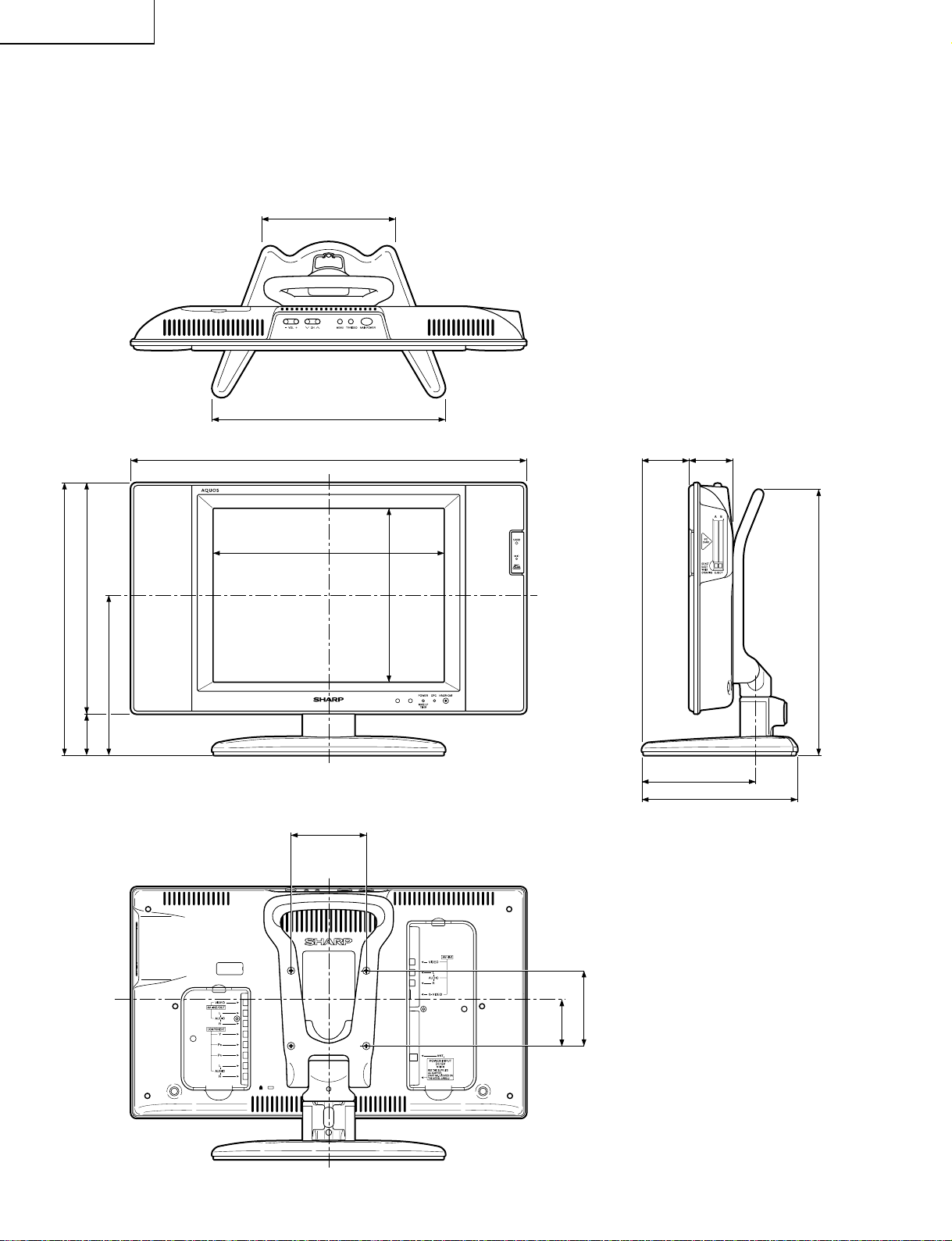
1
/64 (178)
7
127/32 (310)
2023/32 (526)
DIMENSIONS
2
31
/64 (63)
Unit: inch (mm)
219/64 (58)
(including rubber foot)
(363)
64
/
19
14
(307)
32
/
3
12
(56)
32
/
7
2
(213)
64
/
25
8
12
3
/32 (307)
315/16 (100)
(231)
64
/
7
9
61
5
/64 (151)
85/32 (207)
(including rubber foot)
(354)
16
/
15
13
(100)
16
/
(62)
15
64
/
3
29
2
8
Page 9
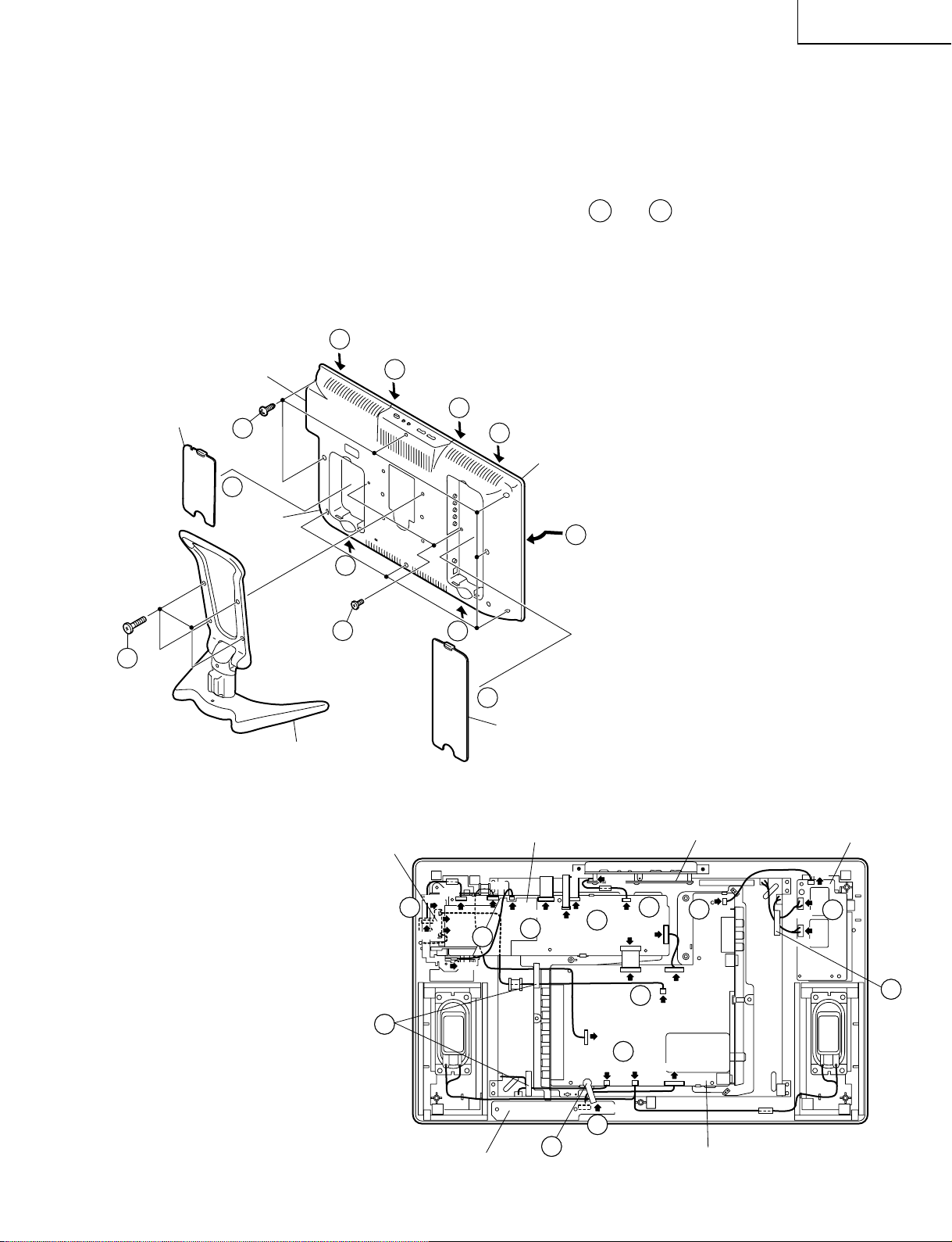
REMOVING OF MAJOR PARTS
P3701
P4001
P3302
SC2001
P4050
P2003
P3704
CN3403
P701
CN2
CN3
CN1
P3202
P3404
P3702
P6500
P6501
P6502
P9001
P5100
SC1201
SC1204
P2005
SC1202
P5201
P2005
P9207
P3201
P9202
P6000
7
7
7
7
7
7
7
7
7
6
6
7
6
Operation PWB
Inverter PWB
Tape
Main PWB
R/C, LED PWB
Tape
Card LED PWB
Analog PWB
Wire Holder
1. Remove the four lock screws from the stand, and detach the stand.
2. Remove the terminal covers (large and small).
3. Remove the two terminal screws.
4. Remove the eight lock screws from the cabinet B.
5. With the card eject button held down, open the cabinet in order of
the cabinet B by sliding it toward the PC card slot.
6. Remove the wire holder and tape, and disconnect the connecting cable.
7. Disconnect all the connectors from all the PWBs.
5-4
5-1
thru
5-6
, and detach
LC-15PX1U
Terminal Cover (S)
1
PC Card Slot
4
2
Cabinet B
Stand
5-6
3
5-3
5-2
5-1
Cabinet A
5
5-5
2
Terminal Cover (L)
9
Page 10
LC-15PX1U
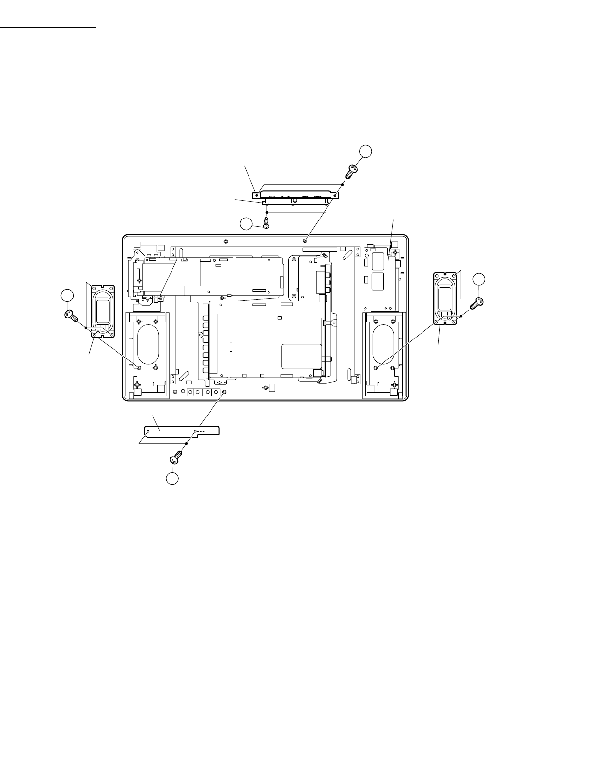
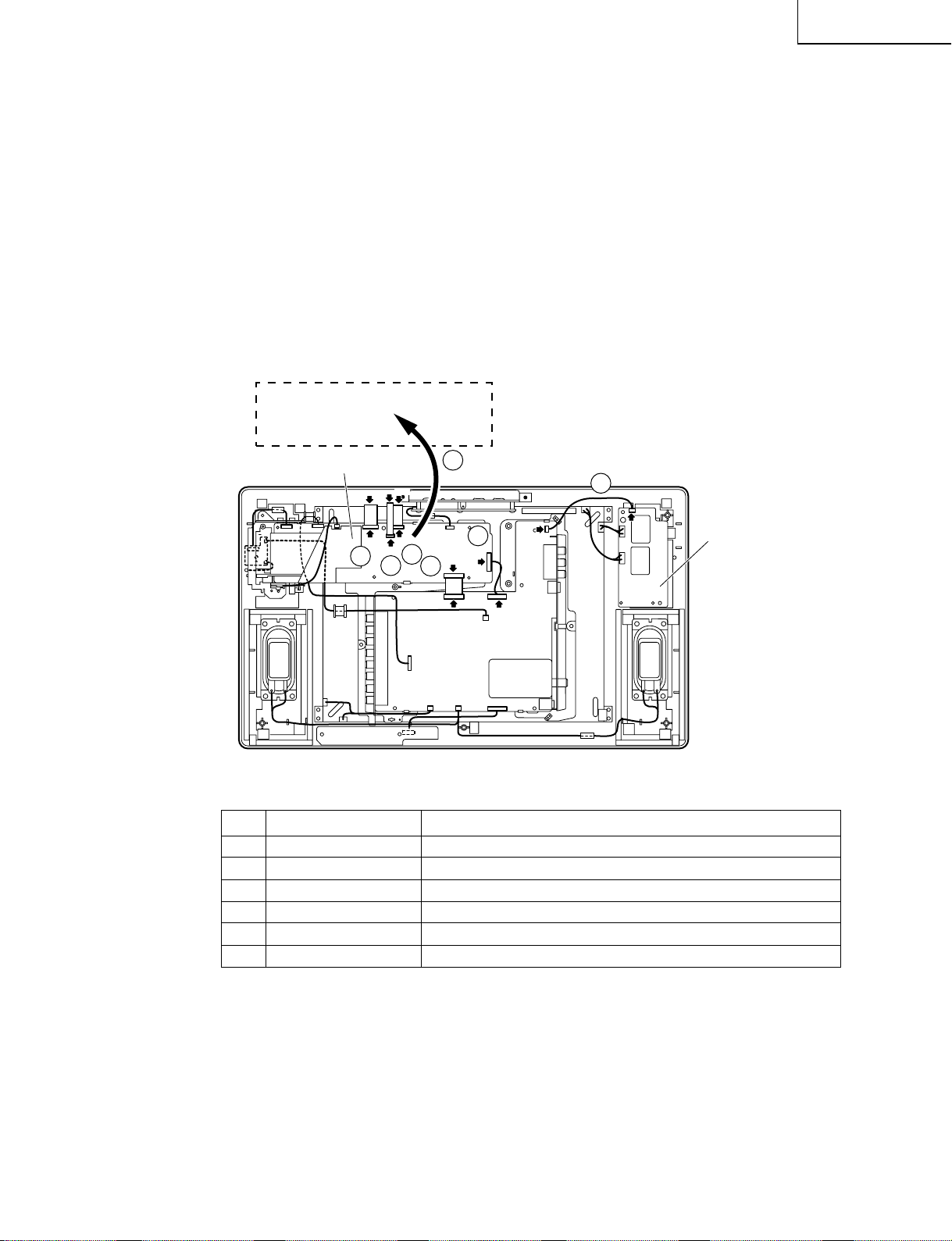
8. Remove the two lock screws from the operation panel (top cover), and detach the operation panel (top cover).
9. Remove the two lock screws from the operation PWB, and detach the operation PWB.
10. Remove the two lock screws from the R/C, LED PWB, and detach the R/C, LED PWB.
11. Remove the three lock screws each from the speakers (left and right), and detach both the speakers.
11
Speaker (R)
Operation PWB
R/C, LED PWB
Operation Panel (Top Cover)
9
Main PWB
Analog PWB
8
Inverter PWB
11
Speaker (L)
10
10
Page 11
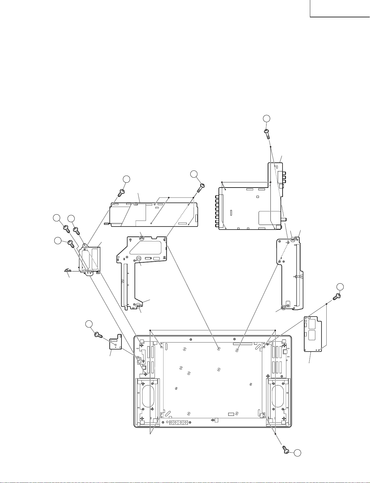
LC-15PX1U
14
14
13
13
16
17
15
12
18
e
Inverter PWB
Main PWB
Analog PWB
Chassis Frame (L)
Chassis Frame (R)
Card Detect PWB
Card Frame
Cover
Card LED PWB
d
a
b
c
12. Remove the two lock screws from the inverter PWB, and detach the inverter PWB.
13. Remove the two lock screw from the card frame cover over, and detach the card frame cover.
14. Remove the five lock screws from the main PWB, and undo the claw a. Detach the main PWB by lifting the area
around the claws and pulling the PWB out.
15. Remove the five lock screws from the analog PWB, and undo the claws b and c. Detach the chassis frame (right)
from the analog PWB by pulling out the terminals. In the same way, undo the claws d and e, and detach the
chassis frame (left) from the analog PWB by pulling out the terminals.
Note: When detaching the main PWB and analog PWB, be careful not to break the PWB-fixing claws.
16. Remove the one lock screw from the card LED PWB, and detach the card LED PWB.
17. Remove the one lock screw from the card detect PWB, and detach the card detect PWB
18. Remove the four lock screws from the LCD panel unit, and detach the LCD panel unit.
11
Page 12
LC-15PX1U
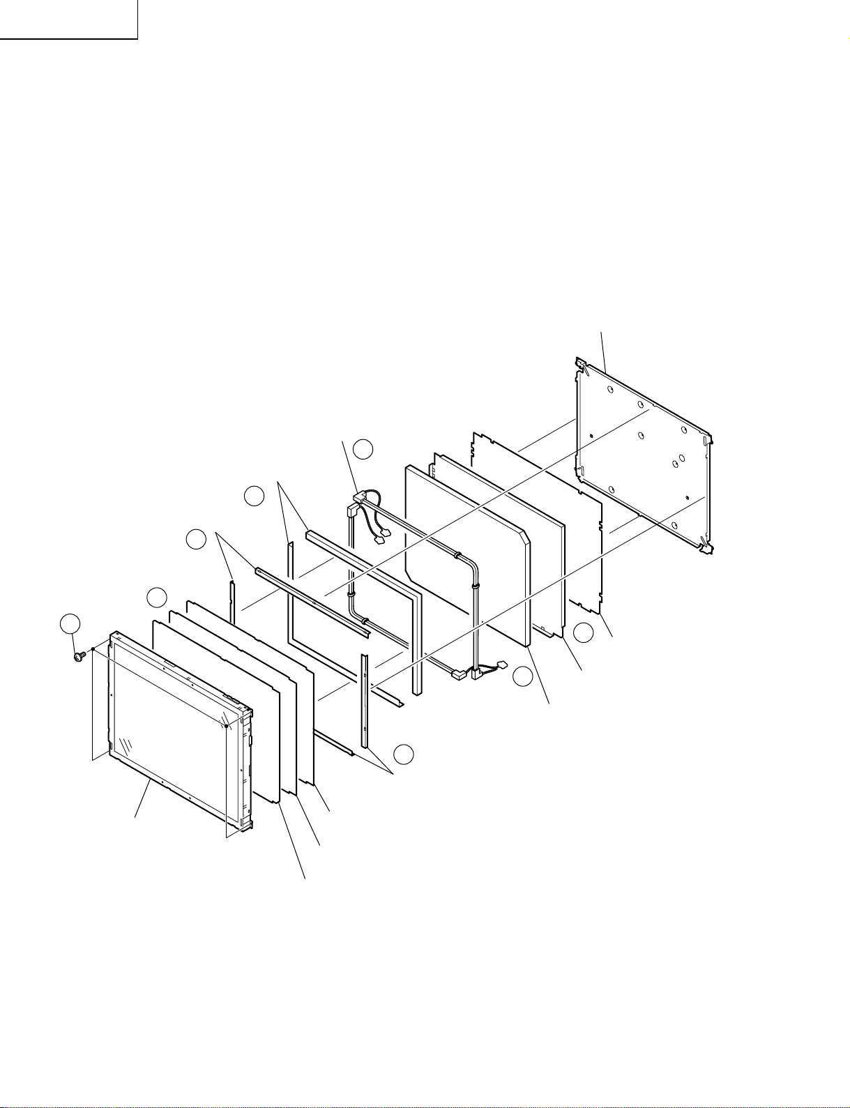
» Precautions in handling the LCD panels
1. Work in a clean room (with humidities below 50%).
2. Be sure to wear an anti-static armband.
3. Handle the panels on an electro-conductive mat.
4. Be careful not to fall, shake and shock the panels.
19. Remove the four lock screws from the LCD panel unit.
20. Detach the diffusion sheet, prism sheet and reflection/deflection sheet.
21. Detach the four reflection mirrors.
22. Detach the two reflection sheets (Cover).
23. Remove the lamp unit.
24. Detach the Light guide plate.
25. Detach the two reflection sheets-1, -2.
Lamp unit
(KLMP-A045WJZZ)
23
Reflection Sheet (Cover)
(PSHEP0307CEZZ)
22
Back Shield
(PSLDMA608WJFW)
20
19
15" LCD Panel Unit
Reflection Mirror
21
21
Reflection Mirror
Diffusion Sheet
(PSHEP0283CEZZ)
Prism Sheet
(PSHEPA141WJZZ)
Reflection/deflection Sheet
(PSHEP0281CEZZ)
25
24
Reflection Sheet-1
(PSHEP0284CEZZ)
Light Guide Plate
(PGiDMA011WJZZ)
Reflection Sheet-2
(PSHEP0285CEZZ)
12
Page 13
LC-15PX1U
» Precautions in servicing the B side (backside) of the main PWB unit
1. Disconnect the FFC from between the main PWB (SC1201) and the LCD panel (CN3), and then connect the
service-specific extension FFC (flat cable) (QCNW-A555WJZZ).
2. Disconnect the FFC from between the main PWB (SC1204) and the LCD panel (CN2), and then connect the
service-specific extension FFC (flat cable) (QCNW-A556WJZZ).
3. Disconnect the FFC from between the main PWB (SC1202) and the LCD panel (CN1), and then connect the
service-specific extension FFC (flat cable) (QCNW-B784WJZZ).
4. Disconnect the FFC from between the main PWB (SC2001) and the analog PWB (SC3403), and then connect the
service-specific extension FFC (flat cable) (QCNW-A556WJZZ).
5. Disconnect the lead from between the analog PWB (P3702) and the inverter (P6502), and then connect the
service-specific extension cable (QCNW-A551WJZZ).
6. Disconnect the lead from between the main PWB (P701) and the analog PWB (P3704), and then connect the
service-specific extension cable (QCNW-B749WJQZ).
7. Remove the lock screws from the main PWB, detach the PWB from the chassis frame, and then turn it over to
service.
Main PWB
(Side-B)
Main PWB
2
CN2
SC1204
CN3
SC1201
1
CN1
SC1202
7
3
SC2001
4
SC3403
Analog PWB
6
P701
P3704
P3702
5
P6502
Inverter PWB
Step Part No. Description
1 QCNW-A555WJZZ Extension Cable 20-pin Main (SC1201)-LCD Panel (CN3)
2 QCNW-A556WJZZ Extension Cable 50-pin Main (SC1204)-LCD Panel (CN2)
3 QCNW-B784WJZZ Extension Cable 30-pin Main (SC1202)-LCD Panel (CN1)
4 QCNW-A556WJZZ Extension Cable 50-pin Main (SC2001)-Analog (SC3403)
5 QCNW-A551WJZZ Extension Cable 3-pin Analog (P3702)-Inverter (P6502)
6 QCNW-B749WJQZ Extension Cable 10-pin Main (P701)-Analog (P3704)
13
Page 14

LC-15PX1U
ADJUSTING PROCEDURE OF EACH SECTION
The best adjustment is made before shipping. If any position deviation is found or after part replace is performed,
adjust as follows.
Preparation for Adjustments
Use the exclusive-use AC adapter or stable DC power supply.
AC adapter: UADP-A044WJPZ
DC power supply: 12 ± 0.5V 5.0A
1.Adjustment Procedure
1-1. Adjusting the checker
Turning on the power (initialization) → Setting the model and size in inches → Transferring the model-specified
data to the E2PROM (I2C) → Calling the adjustment process mode → Starting the adjustment
1-2. Adjusting the finish process
Reassembling the set → Turning on the power → Calling the adjustment process mode (using the remote
controller) → Adjusting the counter bias, TV contrast and white balance
2.Calling the MAIN adjustment process mode
There are the following two ways to choose from.
• Set the Pin (81) (KEY4) or Pin (82) (KEY5) of IC2001 (microprocessor) to "L", turn on the power.
• For servicing, hold down the "TV/VIDEO" and "MENU" keys at once, and turn on the "POWER" switch. (Make
sure the process mode "K" appears at the top left of the screen.) Then press the "CH (Ù)" and "VOL (–)" keys
at once. (Make sure the adjustment process mode screen shows up.) To quit this mode, turn off the power. (Or
turn off the "POWER" switch or use the remote controller’s "OFF" key.)
3.Using the keys for the adjustment process
Selecting a reception channel
• Using the "CH (ù)/(Ù)" key, turn up and down reception (broadcasting) channels.
Just click on the key, and channels are selected on by one.
Hold down the key, and the next receivable channel is searched up and down.
• Adjustment items
Adjust each of the items by using the "MENU", "CURSOR UP/DOWN" and "VOL (+)/(–)" keys (on the set or
on the remote controller).
• Select an adjustment item using the "CURSOR UP/DOWN" key.
• An adjustment item is toggled on and off by activating the MENU SELECT key (next item).
Let’s suppose that the item at the bottom of a page is now selected. When the "MENU" key is activated here,
the item at the top of the next page will be selected.
4.Initialization
4-1. Set pins (81) and (82) of IC2001 (microprocessor) to GND. Turn on the power.
4-2. Check model number (A621). (Can’t Change.)
4-3. Check the inch size (15). (Can’t Change.)
14
Page 15
LC-15PX1U
5. Adjustment
5-1. Counter bias adjustment: COM BIAS on page 2
Adjust the "COM BIAS" setting until the contrast gets optimum (the black portion blackest). The
adjustment guideline is around 120.
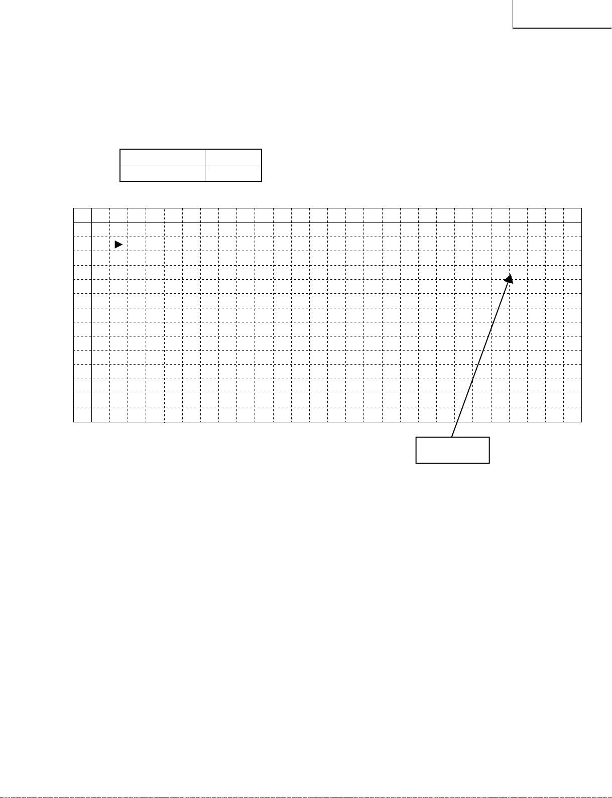
5-2. TAMP adjustment
1) Feed the color bar pattern signal.
2) See if the "Y" reading on adjustment process page 2 is within the range shown below. If not, adjust the
"NTSC TAMP" setting to bring the "Y" reading within the specified range.
Model LC-15PX1U
Adjustment Value 175~185
(Page 2 of adjustment process OSD)
0 1 2 3 4 5 6 7 8 9 10 11 12 13 14 15 16 17 18 19 20 21 22 23 24 25 26
0
1
2
3
4
5
6
7
8
9
10
11
12
13
2
COM B I AS
TAMP L 71
YD TA
TAMP
NTSC TAMP
PAL – TAMP 31
PAL – N
RCUTOF
GCU TOF
BCU TOF
W
R – GAIN
W
G – GA IN
W
B – GA IN
A
H
M
TAMP
F
F
F
1
0
1
1. 0
20
815
819
31
3
3– 5
3– 2
1– 3
9.2
0.0
0
4
1
Y Data
(White 75%)
5-3. White balance adjustment
[Internal signal] White 80% video signal in left portion of screen and White 40% video signal in right portion
of screen
[Adjustment value]
Adjustment specifications Inspection specifications
White 80% x 0.287 Radius from central point Radius from central point
y 0.290 0.002 0.013
White 40% x 0.276 Radius from central point Radius from central point
y 0.270 0.003 0.013
[Adjustment with the bus]
Gain Suppress the two strong colors.
Adjustable range: 0 to -5
Cut-off Vary the red and blue levels.
Keep the green level fixed at 0 (no adjustment).
Adjustable range: -6 to +4
5-4. A/D CONVERTER LEVEL adjustment
1) Feed the color bar pattern signal. (480P, white 75%)
2) Select "AUTO GAIN-OFFSET" and adjust A/D CONVERTER LEVEL automatically by pushing "VOL (+)
(–)" keys (on the set or remote controller).
15
Page 16

LC-15PX1U
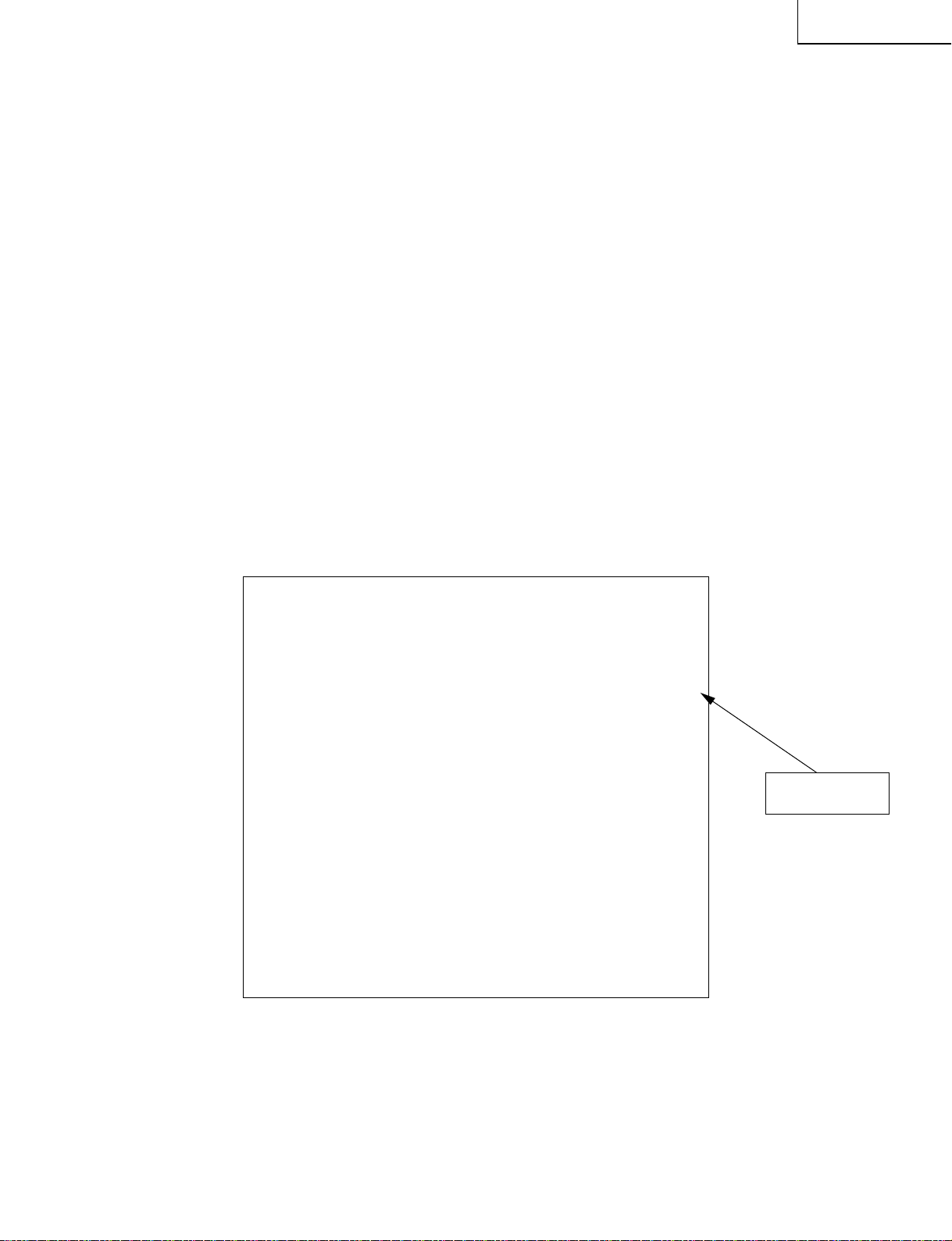
5-5. Other adjustments (SOUND, VPC, S2310, DAC, TUNER, OTHERS, TEXT)
1) Move the cursor to a desired item on page 4 of adjustment process menu. Press the "CURSOR LEFT/
RIGHT" keys, "VOL (+)/(–)" keys or OK key to select the item.
4
I2C DATA 000000000000
I2C DATA WAIT
SOUND
VPC
S2310
DAC
TUNER
OTHERS
TEXT
2) The adjustment process menu of the item appears on the screen. The settings are now ready to change.
Screen with SOUND selected
SOUND1
VOLUME 0
MSP DATA 000000000000
MSP DATA WAIT
AVC OFF
CARRIER MUTE ON
SP TEST OFF
SHUTTER WAIT 100
IGR THR 12D
MSP ASS WAIT 300ms
3) T o go back to page 4 of adjustment process menu, press the "FLASHBACK" key on the remote controller.
16
Page 17
6. Lamp error detection
6-1. Functional description
This LCD color television has a function (lamp error detection) to be turned off automatically for safety when
the lamp or lamp circuit is abnormal.
If the lamp or lamp circuit is abnormal, or some other errors happen, and the lamp error detection is
executed, the followings occur.
1 The main unit of television is turned off 5 seconds after it is turned on. (The power LED on the front side of
TV turns from green to red.)
2 If the situation 1 happens 5 times sequentially , television can not be turned on. (The power LED remains
red.)
6-2. Countermeasures
6-2-1. Check when turning off the lamp error detection
When television is turned off by the lamp error detection mentioned above, it enters the adjustment
process with the power LED red. Entering the adjustment process turns off the error detection and turns
on TV.
This enables the operation check to detect errors in the lamp or lamp circuit.
Check whether "ERROR NO RESET" on line 4, page 1 of the adjustment process is 1 or more. If it is 1 or
more, it indicates the lamp error detection was executed.
6-2-2. Resetting of the lamp error count
After confirming that the lamp or lamp circuit is normal, reset the lamp error count. Select "ERROR NO
RESET" on line 4, page 1 of the adjustment process and set the number to 0 using the "VOL (+)/(–)"
keys.
LC-15PX1U
Page 1 of the adjustment process
1
M O D E L A621
I N C H S I Z E 15
E R R O R N O R E S E T 5
P U B L I C M O D E OFF
V – C H I P 1
C A N A D I A N VCHIP ON
E X T CONTROL OFF
V E R R O M 1. 0 0A G AI B U 0. 0 0 0
Reset 0
Afterwards, perform the operation check to confirm that the lamp error detection does not function.
17
Page 18
LC-15PX1U
7. Functions of the PC card
• PCMCIA card Used at 5V/3.3V
• DM270 (IC5001, 5101) CPU, DSP, DMAC, OSD, NTSC encoder: system control, OSD display, video encoding/
decoding Used at 3.3V (1.5V for DSP)
• DA150 (IC5201, 5202) Audio encoding/decoding
• 128M FLASH (IC5002) Storing the program for DA150 and DM270
• 64M SDRAM (IC5006) Used for temporary data storage and for image data compression and expansion.
• Reg (IC5701, 5702) Conversing 4V/6V to 3.3V/5V for PCMCIA
• Reg (IC5703) Conversing 3.3V to 1.5V for DSP in DM270
"Tips"
1) With this product, showing images recorded with PC or DSC enables you to check the playing system.
2) With PC, showing images recorded with this product enables you to check the recording system.
3) Video is played at the rate in sync with IIS CLOCK signals from audio circuit. For example, if the IIS CLOCK
signals fail to reach the card playing circuit for some reason, the video is played at the lowest rate and is shown
in slow motion.
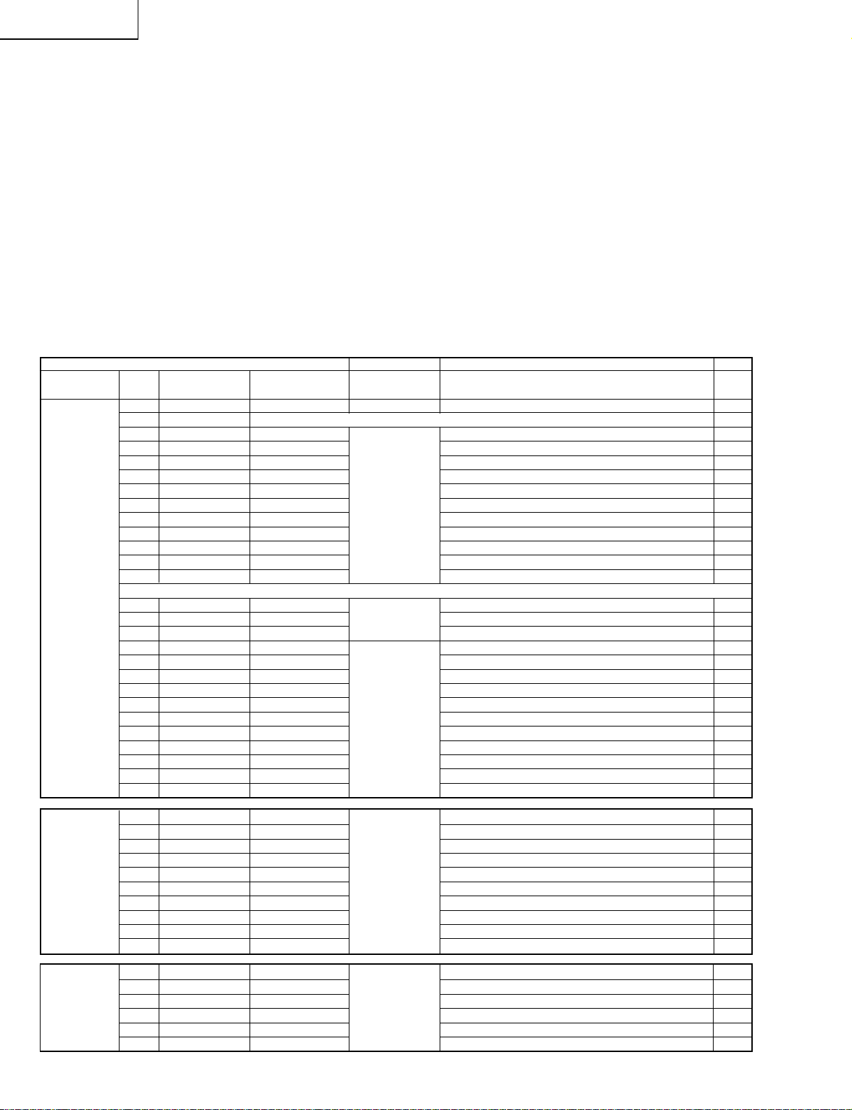
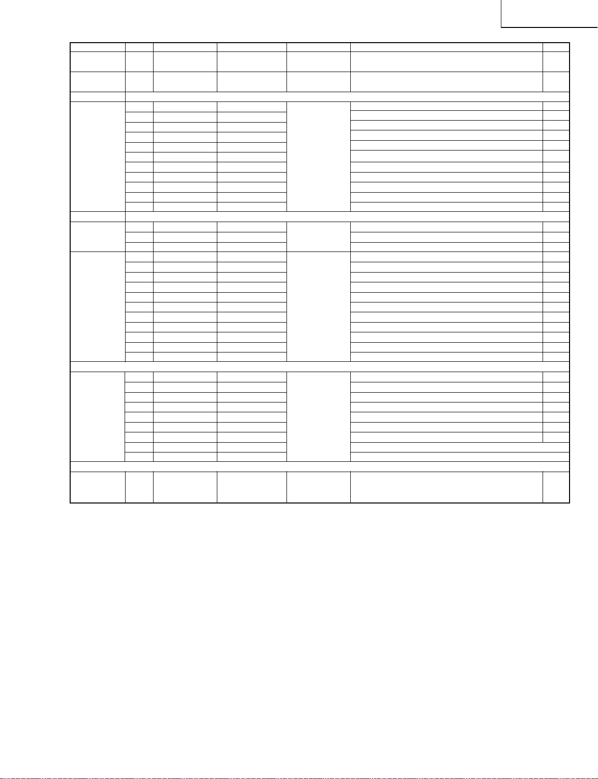
Major input/output terminals on the card system
Card side
IC (connector) Pin No. LSI terminal name Connection diagram Types of signals Explanation for signals I/O
name signal name
DM270 B3.3V_CARD1A B3.3V_CARD1A Power supply Power supply 3.3V for DM270 I
(IC5001, 5101)
103 VIN VIN V signal from VPC to DM270 I
102 HIN HIN H signal from VPC to DM270 I
100 LLC2 (CLK) LLC2 Clock signal from VPC to DM270 I
112 YIN0 YIN0 Data signal 0 from VPC to DM270 I
111 YIN1 YIN1 Data signal 1 from VPC to DM270 I
110 YIN2 YIN2 Video input/output Data signal 2 from VPC to DM270 I
109 YIN3 YIN3 Data signal 3 from VPC to DM270 I
108 YIN4 YIN4 Data signal 4 from VPC to DM270 I
107 YIN5 YIN5 Data signal 5 from VPC to DM270 I
106 YIN6 YIN6 Data signal 6 from VPC to DM270 I
105 YIN7 YIN7 Data signal 7 from VPC to DM270 I
55 RESET RESET Data Reset signal from TV microprocessor to DM270 I
10 CA_DOUT DOUT communication Data signal from TV microprocessor to DM270 I
11 DIN DIN Data signal from DM270 to TV microprocessor I
70 VOUT VOUT V signal from DM270 to IP O
69 HOUT HOUT H signal from DM270 to IP O
68 CKOUT CKOUT Clock signal from DM270 to IP O
81 YOUT0 YOUT0 Data signal 0 from DM270 to IP O
77 YOUT1 YOUT1 Data signal 1 from DM270 to IP O
76 YOUT2 YOUT2 Video input/output Data signal 2 from DM270 to IP O
75 YOUT3 YOUT3 Data signal 3 from DM270 to IP O
74 YOUT4 YOUT4 Data signal 4 from DM270 to IP O
73 YOUT5 YOUT5 Data signal 5 from DM270 to IP O
72 YOUT6 YOUT6 Data signal 6 from DM270 to IP O
71 YOUT7 YOUT7 Data signal 7 from DM270 to IP O
P5201 1 I2S_WS S_WS I2S word strobe L: Right audio input / H: Left audio input I
2 GND
3 I2S_CL S_CL Clock for I2S serial data transmission timing I
4 GND
5 I2SDA_OUT S_DO Audio input/output Audio data input from TV main unit I
6 GND
7 I2SDA_IN1 S_DI In card mode: Card Audio / Not in card mode: Shutter sound O
8 GND
9 I2SDA_IN2 SH_DI
10 GND
Reg 1 IN B4V/6V1_1A 4V/6V output from DC/DC converter to Reg O
(IC5701, 5702) 2 SW B4V/6V1_1A ON/OFF switch I
3 OUT V5EN Power supply 3V power input from DC/DC converter to Reg I
V3EN 5V power input from DC/DC converter to Reg I
4 ADJ For adjustment
5 GND GND GND
18
Page 19
LC-15PX1U
Main Side
IC (connector) Pin No. Terminal name Signal name Types of signals Explanation for signals I/O
name
P701 9 3.3V (SUB) B3.3V2A Power supply Power supply 3.3V for DM270
(NA215WJ)
VPC 57 VS VPC_VS V signal from VPC to DM270 O
(Video decoder) 56 MSY/HS VPC_HS H signal from VPC to DM270 O
IC8801 27 LLC2 LLC2 Clock signal from VPC to DM270 O
40 Y0 VPC_YIN0 Data signal 0 from VPC to DM270 O
39 Y1 VPC_YIN1 Data signal 1 from VPC to DM270 O
38 Y2 VPC_YIN2 Video input/output Data signal 2 from VPC to DM270 O
37 Y3 VPC_YIN3 Data signal 3 from VPC to DM270 O
34 Y4 VPC_YIN4 Data signal 4 from VPC to DM270 O
33 Y5 VPC_YIN5 Data signal 5 from VPC to DM270 O
32 Y6 VPC_YIN6 Data signal 6 from VPC to DM270 O
31 Y7 VPC_YIN7 Data signal 7 from VPC to DM270 O
TV 83 CARDRST RESET
microprocessor 35 SUB_DOUT DOUT Reset Data signal from TV microprocessor to DM270 O
(IC2201) 36 SUB_DIN DIN Data signal from DM270 to TV microprocessor I
I/P conversion 207 VS_P2 VD_VS V signal from DM270 to IP I
IC 208 HS_P2 VD_HS H signal from DM270 to IP I
195 IN_CLK_P2 VD_CKO Clock signal from DM270 to IP I
196 P2_0 VPC_0 Data signal 0 from DM270 to IP I
199 P2_1 VPC_1 Data signal 1 from DM270 to IP I
200 P2_2 VPC_2 Video input/output Data signal 2 from DM270 to IP I
201 P2_3 VPC_3 Data signal 3 from DM270 to IP I
202 P2_4 VPC_4 Data signal 4 from DM270 to IP I
203 P2_5 VPC_5 Data signal 5 from DM270 to IP I
204 P2_6 VPC_6 Data signal 6 from DM270 to IP I
205 P2_7 VPC_7 Data signal 7 from DM270 to IP I
MSP 5 I2S_WS S_WS I2S word strobe L: Right audio input / H: Left audio input O
(Audio processor)
4 I2S_CL S_CL Clock for I2S serial data transmission timing O
6 I2SDA_OUT S_DO Audio input/output Audio data input from TV main unit O
7 I2SDA_IN1 S_DI In card mode: Card Audio / Not in card mode: Shutter sound I
DC/DC
converter B4V/6V1_1A B4V/6V1_1A Power supply 4V/6V output from DC/DC converter to Reg O
IC704, 707 B4V/6V2_1A B4V/6V2_1A
Data communication,
Reset signal from TV microprocessor to DM270 O
Abolished
19
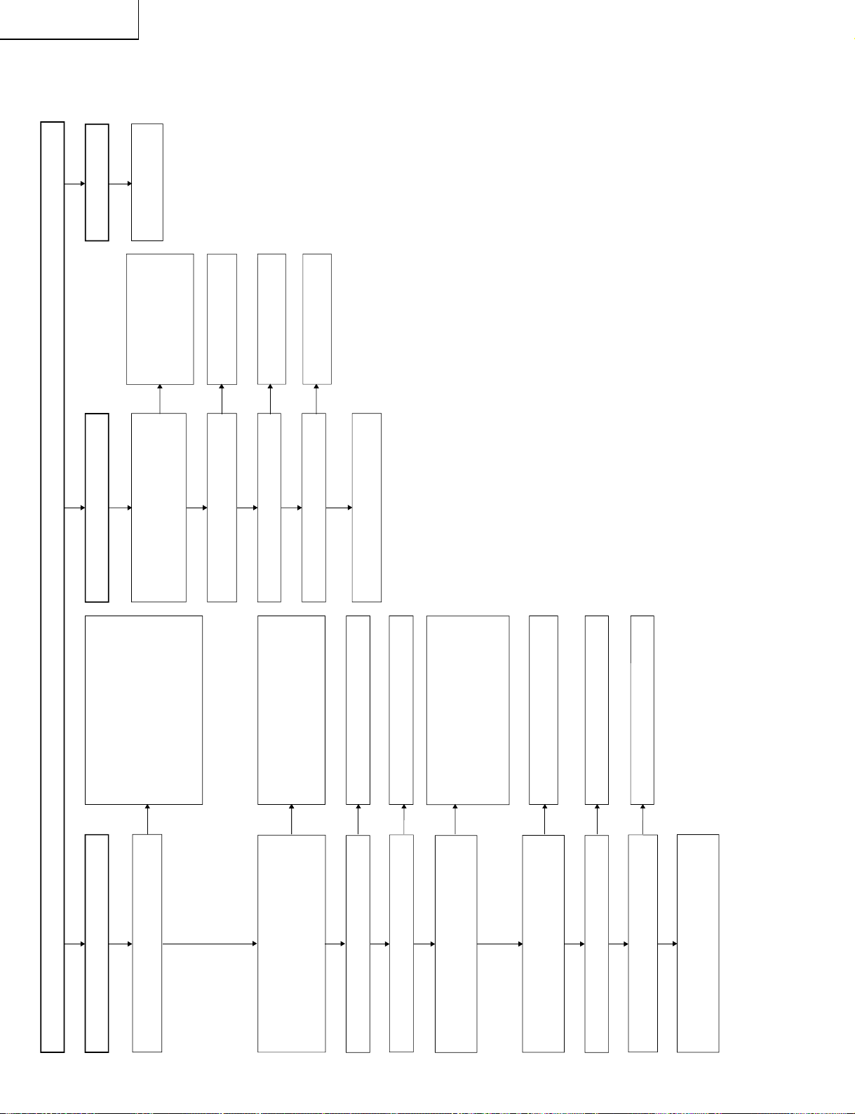
Page 20
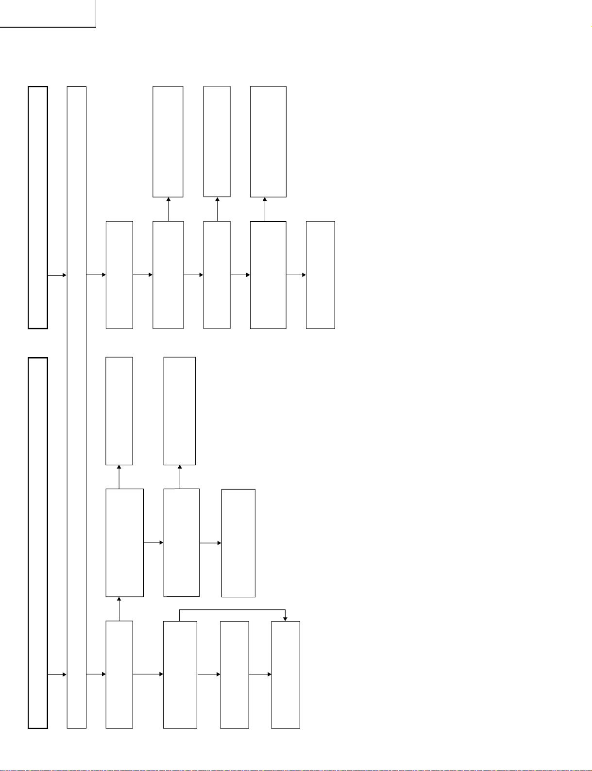
LC-15PX1U
No picture and sound
Check all the settings on the microprocessor's adjust process menu.
Fluorescent light in trouble
YES
YES
YES
YES
YES
YES
NO
NO
NO
NO
NO
NO
YES
YES
NO
Does the load side keep
normal circuits when F3701
and F3702 are disconnected?
Are F3701, F3702, F6501 and
F6502 normal?
Do Q6502 and Q6505 keep
normal circuits?
Check Q6502, Q6505 and
their peripheral circuits.
Check S4053 and the
connecting cables.
Check the connecting cables
and the peripheral circuits of
J3701.
Are pins (10) and (11) of
IC1201 "H"?
Are the oscillation waves from
the primary sides of T6500
thru T6502 normal?
Check and replace the
fluorescent light.
Check the connecting cables
and the peripheral circuits of
Q6500 thru Q6505.
Check that line, IC1201 and
their peripheral circuits.
Are +35V, +9V, +5V and -12V
on the secondary side output
at T701 normal?
Are pins (14) of IC702 thru
IC707 normal? (1.35V-2.05V)
Check the load side.
Do Q716, S4053 and the
peripheral circuits on the
primary side of T701 keep
normal circuits?
Replace F3701 and F3702.
Are F3701 and F3702
normal?
TROUBLE SHOOTING TABLE
20
Page 21
NO
NO
NO
YES
YES
YES
NO
NO
NO
NO
YES
YES
YES
YES
NO
YES
NO
YES
NO
NO
YES
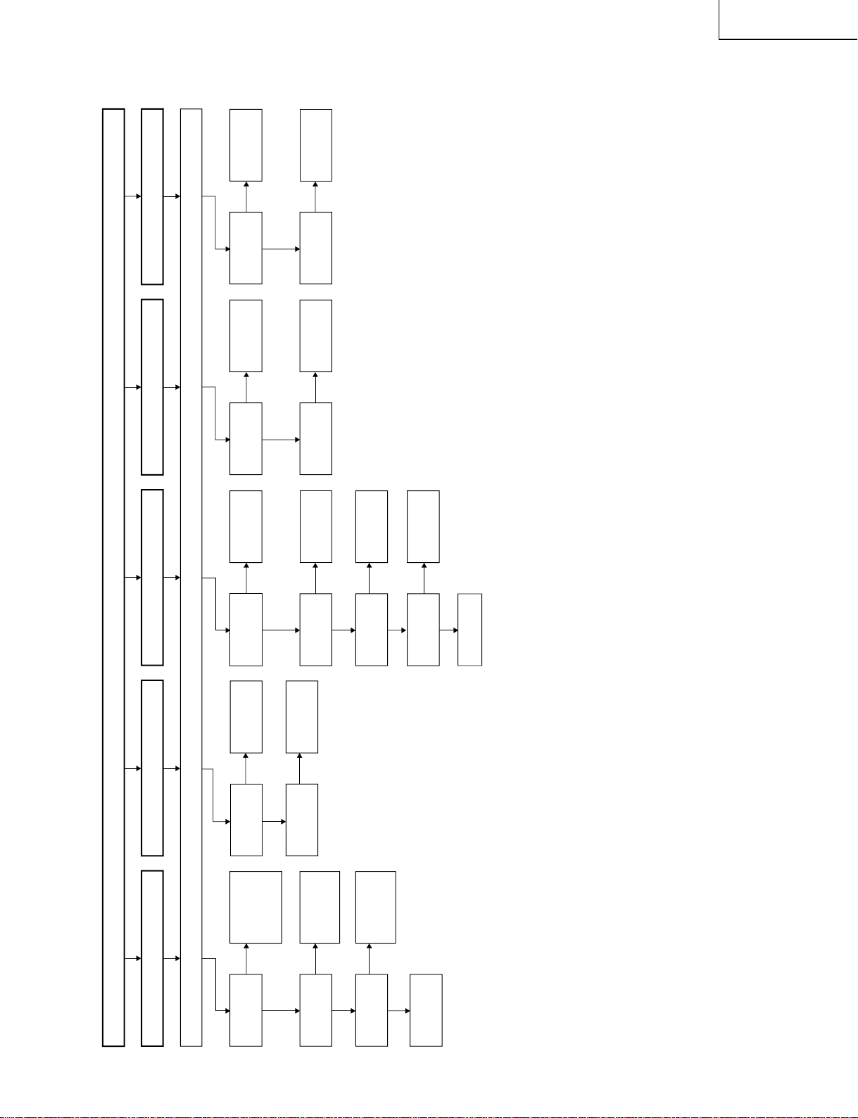
No video output (1/2)
Make sure that the microprocessor's adjustment process and menu settings are all as specified.
No images at all
Does the IC1201
test pattern
appear?
Check IC1201 and its
peripheral circuits.
Check also the LCD
panel voltage and
waveform.
Are the input and
output of IC3401
as specified?
Check IC3401
and its peripheral
circuits.
Is the input of
IC8801 as
specified?
Check the signal
input line of
IC8801.
Are the voltages at
pins (6), (7) and (9) of
tuner as specified?
Check the
voltage line.
Is the output at
pin (19) of tuner
as specified?
Check the tuner
and its peripheral
circuits.
Is the input at pin
(1) of IC3401 as
specified?
Check the line
in question.
Is the output of
IC3401 as
specified?
Check IC3401
and its peripheral
circuits.
Is the input at pin
(23) of IC3401 as
specified?
Check the line
in question.
Is the output of
IC3401 as
specified?
Check IC3401 and
its peripheral
circuits.
Is the input at pin
(47) of IC3401 as
specified?
Check the line
in question.
Is the output of
IC3401 as
specified?
Check the line
in question.
Check IC3401
and its peripheral
circuits.
Does the card
circuit test
pattern appear?
Check IC8501 and
its peripheral
circuits. Check also
the card circuit.
Does the
IC8801 test
pattern appear?
Check the signal
input line of
IC8801.
Check IC8801 and its
peripheral circuits.
Check also the card
circuit signal input.
No TV, AV1 and AV2 images
No TV images No AV1 images No AV2 images
*1 thru *3: Getting the test patterns
displayed is referred to on the next page.
*1
*2
*3
TROUBLE SHOOTING TABLE (Continued)
LC-15PX1U
21
Page 22

LC-15PX1U
TROUBLE SHOOTING TABLE (Continued)
1. Getting the card circuit test pattern displayed (*2)
1-1. Hold down the "MENU" and "TV/VIDEO" keys of the set, and turn on the "MAIN POWER" switch.
1-2. Make sure that "K" shows up in yellow at the left top of the screen.
1-3. Press the "APPS" key of the remote controller, and the card test menu appears.
1-4. Select "F3" on the 3rd line and press the "ENTER" key of the remote controller, and the test pattern
appears onscreen for about 2 seconds.
2. Getting the IC1201 test pattern displayed (*1)
2-1. Take the above steps 1-1 and 1-2. Hold the "CH (Ù) "and "VOL (–)" keys of the set at once.
2-2. The adjustment mode page number "1" shows up in red at the left top of the screen. The adjustment items
are listed below the number.
2-3. Using the "CURSOR UP/DOWN" keys of the remote controller, make Page 4 appear.
2-4. Select "G/A" on the 9th line and press the "ENTER" key, and the IC1201 adjustment menu comes on ("G/
A1" shows up in red at the left top).
2-5. Select "G/A TEST PATTERN" on the 1st line. Turn on and off with the "CURSOR LEFT/RIGHT" keys to get
the test pattern onscreen.
2-6. Adjust the settings and return to OFF.
3. Getting the IC8801 test pattern displayed (*3)
3-1. Take the above steps 2-1, 2-2 and 2-3 to make Page 4 appear.
3-2. Select "VPC" on the 4th line and press the "ENTER" key, and the IC8801 adjustment menu comes on
("VPC1" shows up in red at the left top).
3-3. Select "TEST PATTERN" on the 1st line. Using the "CURSOR RIGHT" key, adjust the setting to other than
"0" to get the test pattern onscreen.
3-4. Adjust the settings and return to "0".
22
Page 23
NO
NO
YES
NO
NO
YES
NO
YES
YES
NO
NO
YES
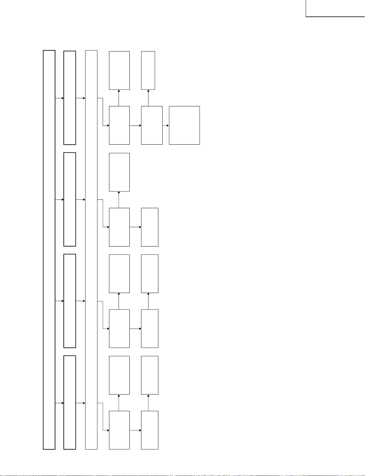
No video output (2/2)
Make sure that the microprocessor's adjustment process and menu settings are all as specified.
No S video images
Are the inputs at
pins (71) and (72)
of IC8801 as
specified?
Check the line in
question.
Are the inputs at
pins (1), (5) and
(25) of IC3403 as
specified?
Check the line in
question.
Are the inputs at
pins (4), (5), (6)
and (72) of IC8801
as specified?
Check IC3402 and
IC3403 as well as
their peripheral
circuits.
Are the inputs at
pins (43), (48), (49)
and (54) of IC8701
as specified?
Check the line in
question.
Check IC8701 and
its peripheral
circuits.
Check the file card
media and card
adaptor.
Check the line in
question.
Are the voltages at
pins (37) thru (40)
and (114) thru
(117) of P5601 as
specified?
Check the data,
address and control
lines (IC5601 thru
IC5618) that run
from the card slot
to IC5001 and
IC5101.
Check the
power line.
Are the inputs at
pins (3) and (5) of
IC3401 as
specified?
Check the SY/SC
lines of J3401 and
their peripheral
circuits.
No 480i component video images
No 480P, 1080i and 720P component
video images
No card images
TROUBLE SHOOTING TABLE (Continued)
LC-15PX1U
23
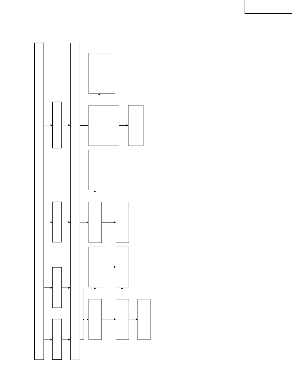
Page 24
LC-15PX1U
No sound
No sound from speakers
YES
YES
YES
YES
YES
YES
NO
YES
YES
YES
YES
NO
NO
NO
NO
NO
NO
NO
NO
NO
Check the following.
1 No audio output from TV ... Check the
peripheral circuits of Q3203, Q3204 and
TU3000.
2 No audio output from AV1 input ... Check
J3402 thru pins (2) and (4) of IC3401.
3 No audio output from AV2 input ... Check
J3404 thru pins (22) and (24) of IC3401.
4
No audio output from COMPONENT input
... Check J3406 thru pins (46) and (48) of
IC3401.
Is there the audio output in any input mode (TV, AV1,
AV2 and COMPONENT)?
Check the following.
1
Is the monitor output setting at "Audio fixed"?
2
Is the sound volume loud enough?
3
Is the mute mode released?
4
Are the headphones unplugged?
Is the power supply voltage at each circuit normal?
Pin (8) of IC3301 and pin (39) of IC3201 Approx. +8V
Pins (11), (12), (13), (65) and (66) of IC3201 Approx. +5V
No sound from monitor output
Is there the audio signal output at pins
(36)(Rch) and (37)(Lch) of IC3201?
Is pin (55) of IC2001 "H"?
Is the signal from the Q3403 collector "L"?
Check pins (33)(Rch) and (34)(Lch) of IC3201
thru pins (4)(Lch) and (2)(Rch) of J3404.
Check the following.
1
Is there the audio output from speakers?
2
Is the monitor output connected correctly?
3
Is the mute mode released?
No sound from the
headphones
Check the line from J4201
to IC3305 and IC3201.
Check the following.
1
Go to "No Audio from
Speakers".
2
Connect the monitor output
correctly.
3
Release the mute mode.
Check the peripheral circuits of
IC3201.
Check pin (4) of J4021 thru pin
(58) of IC2001.
Check pin (55) of IC2001 thru
Q2203, and Q2201.
Is there the control signal input at each pin of IC3201?
Pin (2) of IC3201 SCL1
Pin (3) of IC3201 SDA1
Are the oscillation waves from pins (71) and (72) of
IC3201 normal?
Check pins (29) and (30) of IC2001 thru pins
(2) and (3) of IC3201.
Check the peripheral circuits of X3201.
Is there the audio signal output at pins (27)(Rch) and
(28)(Lch) of IC3201?
Check pins (27)(Rch) and (28)(Lch) of IC3201 thru
pins (7)(Rch) and (1)(Lch) of IC3304, and the
peripheral circuits of IC3301.
Check the peripheral circuits of IC3201.
YES
YES
NO
NO
Is the voltage at pin (7) (power input terminal) of
IC3304 as specified (about +12V)?
Check the AC adaptor as well as the line from
AC adaptor to pin (7) of IC3304.
Is the voltage at pin (5) (standby control terminal) of
IC3304 as specified (about +2.8V)?
Check the line from pin (56) of IC2001 to pin
(5) of IC3304.
Recheck the following.
1
Set the monitor output to "Audio fixed".
2
Increase the sound volume.
3
Release the mute mode.
4
Unplug the headphones.
Check the following.
+8V system ... Check the peripheral circuits of
Q3711 thru pin (8) of IC3301
and pin (39) of IC3201.
+5V system ... Check the IC702, Q713 output
5V (SUB)
line thru each +5V input pin of
IC3201.
TROUBLE SHOOTING TABLE (Continued)
24
Page 25
TROUBLE SHOOTING TABLE (Continued)
No Colors
No TV colors
No VIDEO colors No S-VIDEO colors
No COMPONENT colors
Check all the settings on the microprocessor's adjust process menu.
YES
YES
YES
NO
NO
Is the input at pin (71)
of IC8801 normal?
Are the input at pins (4)
and (6) of IC8801
normal? (480i)
Is the input at pins (43)
and (54) of IC8701
normal? (480i, 1080i,
720p)
Check the CB and CR
lines of SC2001 and
their peripheral circuits.
Check the output at
IC8801 (480i), output
at IC8701 (480i, 1080i,
720p), input/output at
IC1201 and their
peripheral circuits.
Is the output at pin (40)
of IC3401 normal?
NO
Check IC3401 and its
peripheral circuits.
NO
Check the output of
IC8801, input / output
of IC1201 and its
peripheral circuits.
Check the Video lines of
IC3401, SC2001 and
their peripheral circuits.
YES
NO
Is the input at pin (71)
of IC8801 normal?
Check between SC
input of J3401 and pin
(71) of IC 8801.
Check the output of
IC8801 input / output of
IC1201 and its
peripheral circuits.
LC-15PX1U
25
Page 26
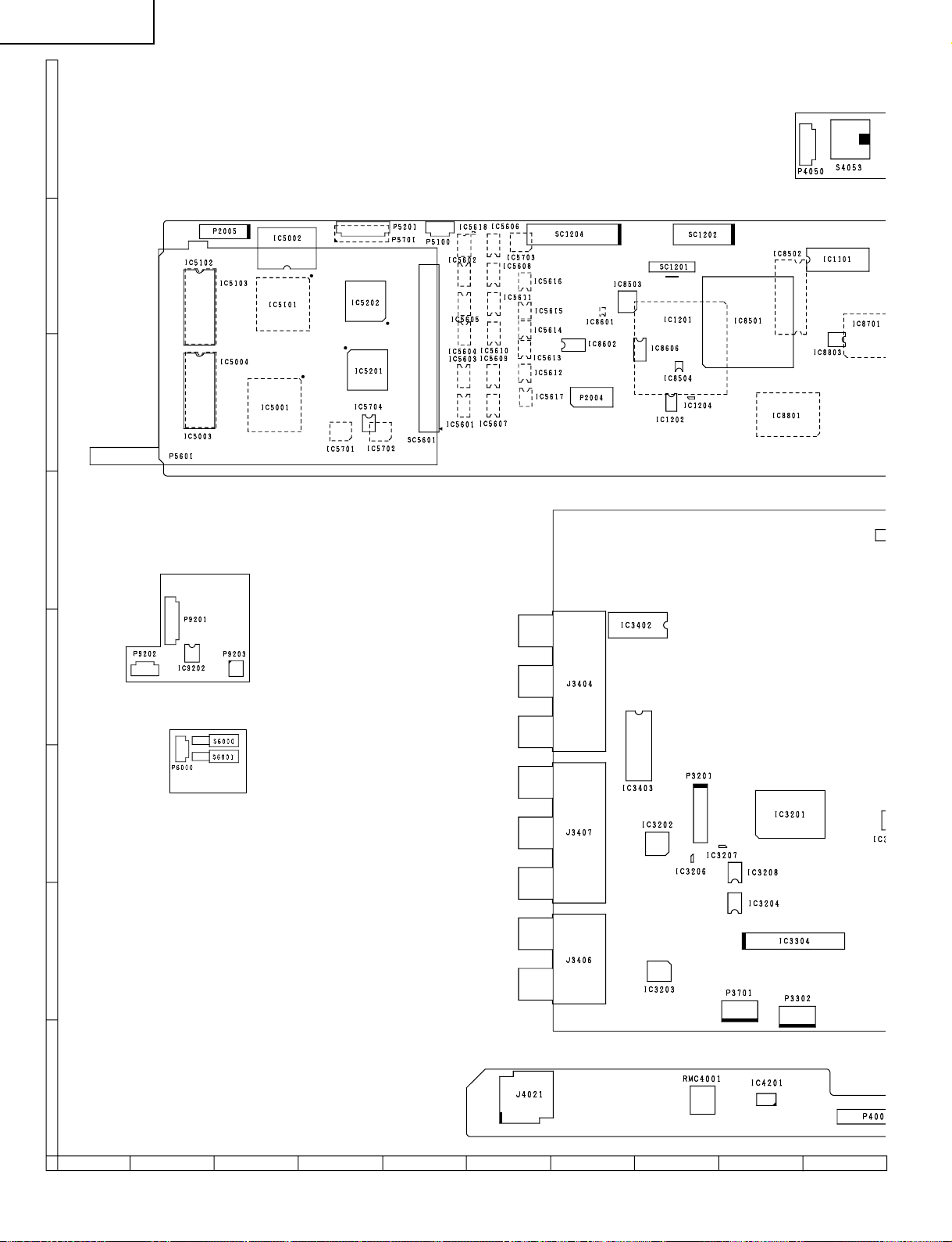
LC-15PX1U
CHASSIS LAYOUT
H
G
F
MAIN Unit
E
D
C
B
CARD LED Unit
CARD DETECT Unit
R/C, LED Unit
A
87109654321
26
Page 27
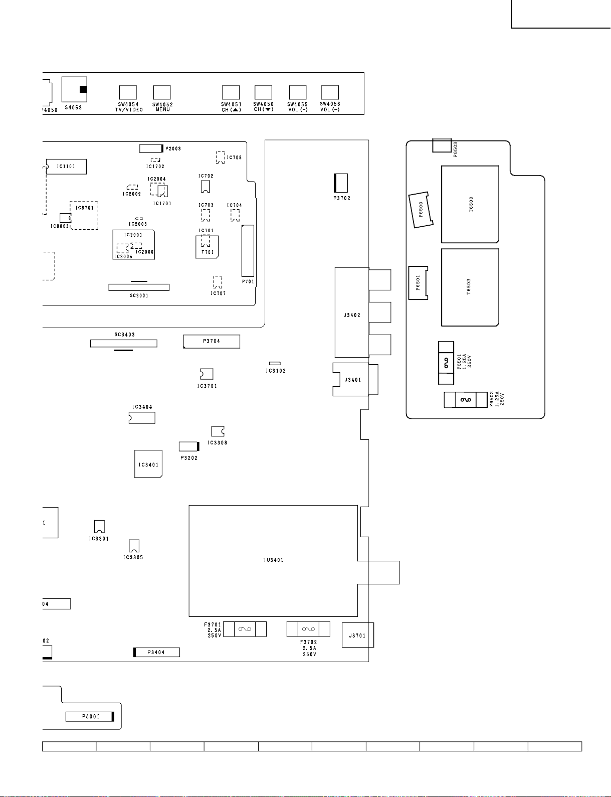
OPERATION Unit
LC-15PX1U
ANALOG Unit
INVERTER Unit
27
1716 1918151413121110
Page 28
LC-15PX1U
2
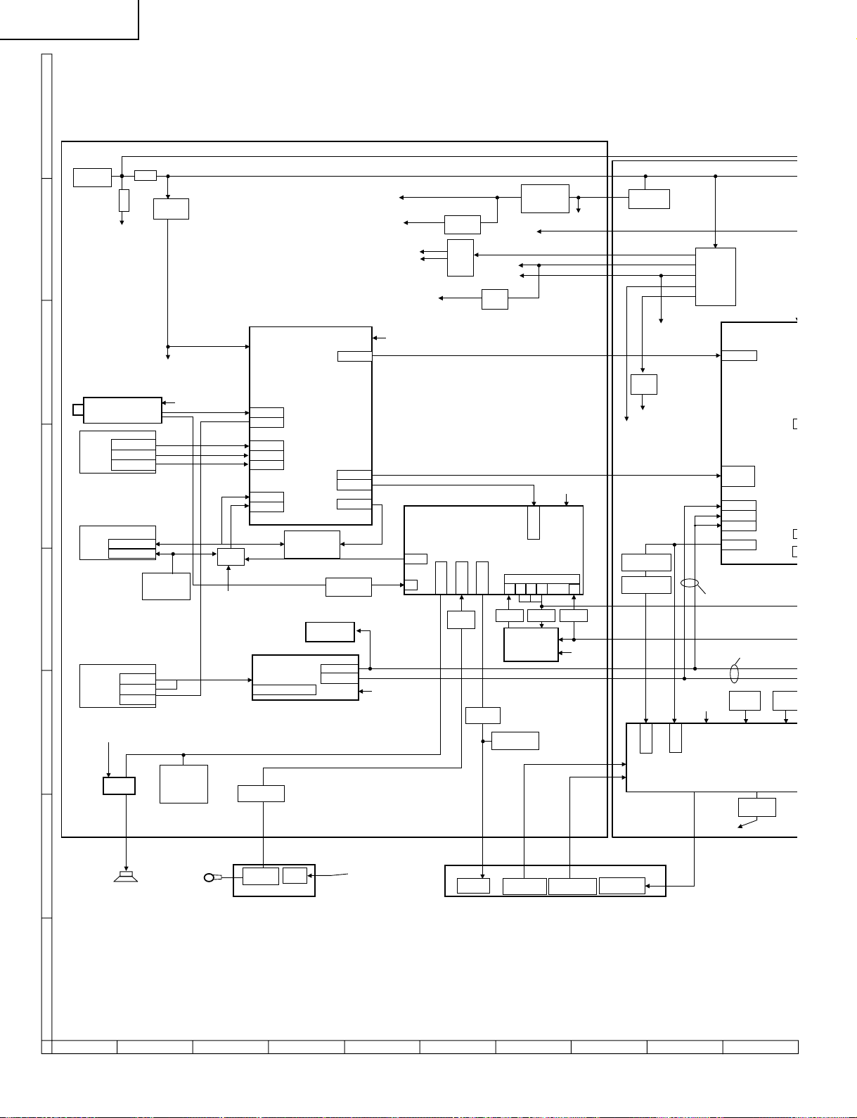
BLOCK DIAGRAM
H
G
F
E
D
C
J3701
(DC 12V IN )
Sound Vcc
(U/V TUNER)
(AV1 input)
J3401
J3402
(AV2 IN/OUT)
J3404
(COMPONENT input)
J3406
J3407
Sound Vcc
F3702
TU3401
S Y/C-IN
VIDEO-IN
AUDIO-IN
Video-in/out
L/R-in/out
L/R-in
Pb/Pr-in
F3701
Q3401,Q3402
Q3403,D3404
Y-in
IC3102
(9V_REG.)
AN_9V
CVBS
(MUTE)
Q3107,Q3110
5V(MAIN)
Q3711
Q3715,D3304
(Mute)
Q3117
(Pow cont.)
3.3V(SUB)
9V
7 6 5 4
IC3202
(EQUALIZER)
IN L/R
I2S in/out
IC3204IC3206
5V_SUB
I2C
17
IC3207
I2C
B5V(D_SW) 1A
8V
IC3201
(Sound Processor)
TV L/R
DACM L/R
67
IC3203
(2.5V_REG)
IC3701
Q3709
Q3710
(REG)
MONO IN
IC3308
(MIC FLT)
DACA L/R
IC3305
(HP Amp)
2.5V
24V
31V
IC3401
(AV SELECT)
I2C
TV-V
CVBS
CVBS
IC3404
(SW)
AN_9V
U/V
Video in
L/R in
VIDEO1
Y/C in
Video in
L/R in
VIDEO2
Video in
L/R in
(75ΩDRIVE /SW)
IC3403
(VIDEO FILTER)
COMPONENT in
Q3414,Q3415
Q3417,Q3405
MONITOR OUT
Q3203, Q3204
(Amp & Buffer)
IC3402
(TA1318AF)
Y out
Pr/Pb out
MAIN OUT
V out 1
Y/C out
L/R out
V out
I2C
I2C
IC702,Q713
(5V_REG)
IC1701
Q1703
-7.5V
B-7V1A
Q8801
(Video Buffer)
Q8802,IC8803
(CSYNC Sep)
B5V_MAIN1A
CSYNC
CVIN
-12V
35V
-7V
IC701,Q716
T701
9V
(REG)
5V
Cr Cb
I2C
Y
480i
IC8801
VPC3230D
Video in 2
Video in 1
C in
Cb/Cr in
Y in
Video in 4
Video out
480p/1080i/720p
IC2005
(EEPROM)
IC2003
(RESET)
I
B
A
IC3304
(Amp)
SP L/R
Q3301,Q3302
Q3303
Q3207,D3205
(Mute)
Mic
IC3301
(Pre Amp)
IC9202
(Mic Amp)
CARD LED UNIT
D9201
(LED)
CARD LED
Cont.
28
J4021
(HP Jack)
IC4201
(OPC sensor)
RMC4001
(R/C Receiver)
R/C, LED UNIT
D4001,D4002
(LED)
87109654321
CARD LED
Cont.
Q2012
(LED Driver)
Page 29
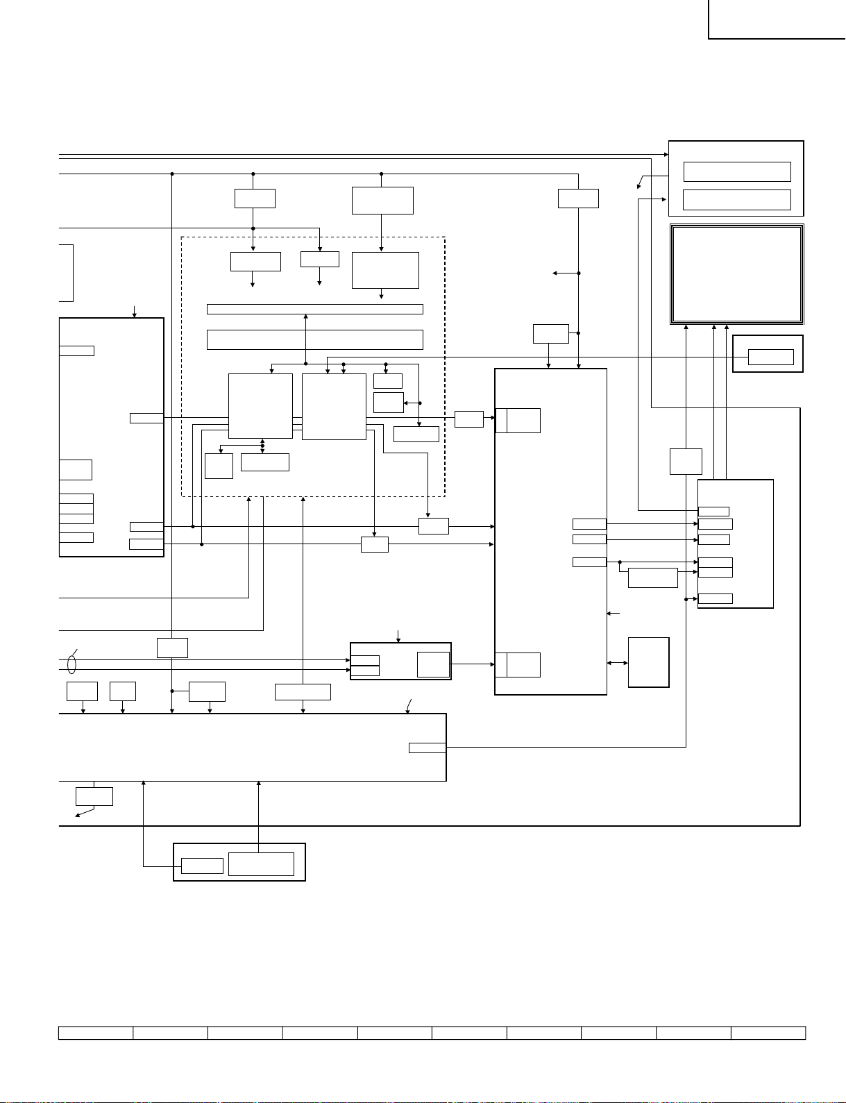
INVERTER UNIT
LAMP DRIVE
LC-15PX1U
16
IC8801
VPC3230D
Video in 2
Video in 1
C in
Cb/Cr in
Y in
Video in 4
Video out
I2C
ITU_R-656
LLC2
VS/HS
CARD Circuit
IC5102
IC5103
(SDRAM)
IC708,Q725
(3.3V_REG)
Q8602,Q8601
(Card Pow_Cont)
3.3V
P5601 (CARD Slot)
IC5601-IC5618
(BUS Control & Buffer)
IC5101
(Media Processor)
IC5202
(Media Pro_sub)
IC5703
(1.5V_REG)
1.5V
IC5001
(OA Processor)
IC704, Q714
IC707, Q721
(4V/6V_REG & Cont)
IC5701, Q5701
IC5702, Q5702
IC5704
(3.3V/5V_REG & Cont)
3.3V/5V
IC5002
(FLASH)
IC5003
IC5004
(SDRAM)
IC5201
(OA Pro_sub)
IC8606
(SW)
IC8601
(CLK SW)
IC8602
(Buffer)
IC703,Q712
(3.3V_REG)
B3.3V_2A
IC8503
(1.8V_REG)
IC8501
(DIGITAL VIDEO FORMAT
CONVERTER)
ITU-R-656
in
Port 2
• IP CONVERSION
• FRAME RATE CONVERSION
• SCALING
Y/U/V
• CTI, WHITE BALANCE
• BRIGHT, CONTRAST
COLOR, TINT, SHARPNESS
R/G/B
HS/VS/DE
CLK out
L_ERR
IC1202,IC1204
LAMP ERROR CHECK
LCD PANEL
VGA
20/15
IC1101
(Gradation
Cont.)
IC1201
(OSD MIX / LCD
CONTROLLER)
OFL1,OSC
R/G/B
HS/VS/DE
CLK
CLK_2X
CARD DETECT UNIT
S6000,S6001
(Detect SW)
480p/1080i/720p
IC2005
(EEPROM)
Q2012
(LED Driver)
LED
IC2003
(RESET)
IC2004
(5V REG)
OPERATION UNIT
IC2002
(3.3V REG)
IC2001
(MPU)
S4053
(POWER SW)
S4050,S4051,S4052
S4054,S4055,S4056
(Control SW)
IC2006,Q2010
(Din/Dout cont.)
Cr Cb
Y
IC8701 (ADC)
48
43.54
DA/DLK
I2C
I2C
IC8502
(SDRAM)
L_ERR
VS/HS/
G/B/R
CK
RGB24bit
YUV4:4:4
HS/VS/CLK
Port 1
VS/HS/
CK
R/G/B
DA/DLK
29
1716 1918151413121110
Page 30
LC-15PX1U
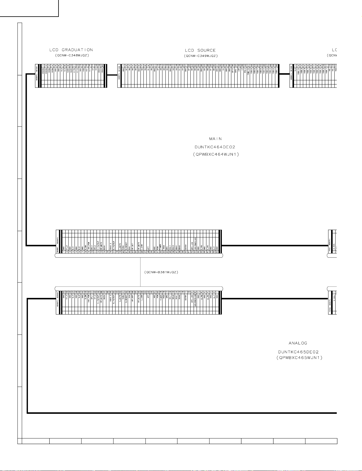
OVERALL WIRING DIAGRAM
H
G
F
E
D
C
B
A
87109654321
30
Page 31

LC-15PX1U
31
1716 1918151413121110
Page 32

LC-15PX1U
DESCRIPTION OF SCHEMATIC DIAGRAM
VOL T AGE MEASUREMENT CONDITION:
1. The voltages at test points are measured on
exclusive AC adaptor and the stable supply voltage
of AC 120V. Signals are fed by a color bar signal
generator for servicing purpose and the above
voltages are measured with a 20k ohm/V tester.
INDICA TION OF RESIST OR & CAPACITOR:
RESISTOR
1. The unit of resistance “Ω” is omitted.
(K=kΩ=1000 Ω, M=MΩ).
2. All resistors are ± 5%, unless otherwise noted.
(J= ± 5%, F= ± 1%, D= ± 0.5%)
3. All resistors are 1/16W, unless otherwise noted.
CAPACITOR
1. All capacitors are µF, unless otherwise noted.
(P=pF=µµF).
2. All capacitors are 50V, unless otherwise noted.
CAUTION:
This circuit diagram is original one, therefore there may be a
slight difference from yours.
SAFETY NOTES:
1.DISCONNECT THE AC PLUG FROM THE AC
OUTLET BEFORE REPLACING PARTS.
2.SEMICONDUCTOR HEAT SINKS SHOULD BE
REGARDED AS POTENTIAL SHOCK HAZARDS
WHEN THE CHASSIS IS OPERATING.
IMPORTANT SAFETY NOTICE:
PARTS MARKED WITH “å” ( ) ARE
IMPORTANT FOR MAINTAINING THE SAFETY OF
THE SET. BE SURE TO REPLACE THESE PARTS
WITH SPECIFIED ONES FOR MAINTAINING THE
SAFETY AND PERFORMANCE OF THE SET.
AVIS DE SECURITE IMPORTANT:
LES PIECES MARQUEES “å” ( )SONT
IMPORTANTES POUR MAINTENIR LA SECURITE
DE L'APP AREIL.
NE REMPLACER CES PIEDES QUE PAR DES
PIECES DONT LE NUMERO EST SPECIFIE POUR
MAINTENIR LA SECURITE ET PROTEGER LE BON
FONCTIONNEMENT DE L'APPAREIL.
32
Page 33

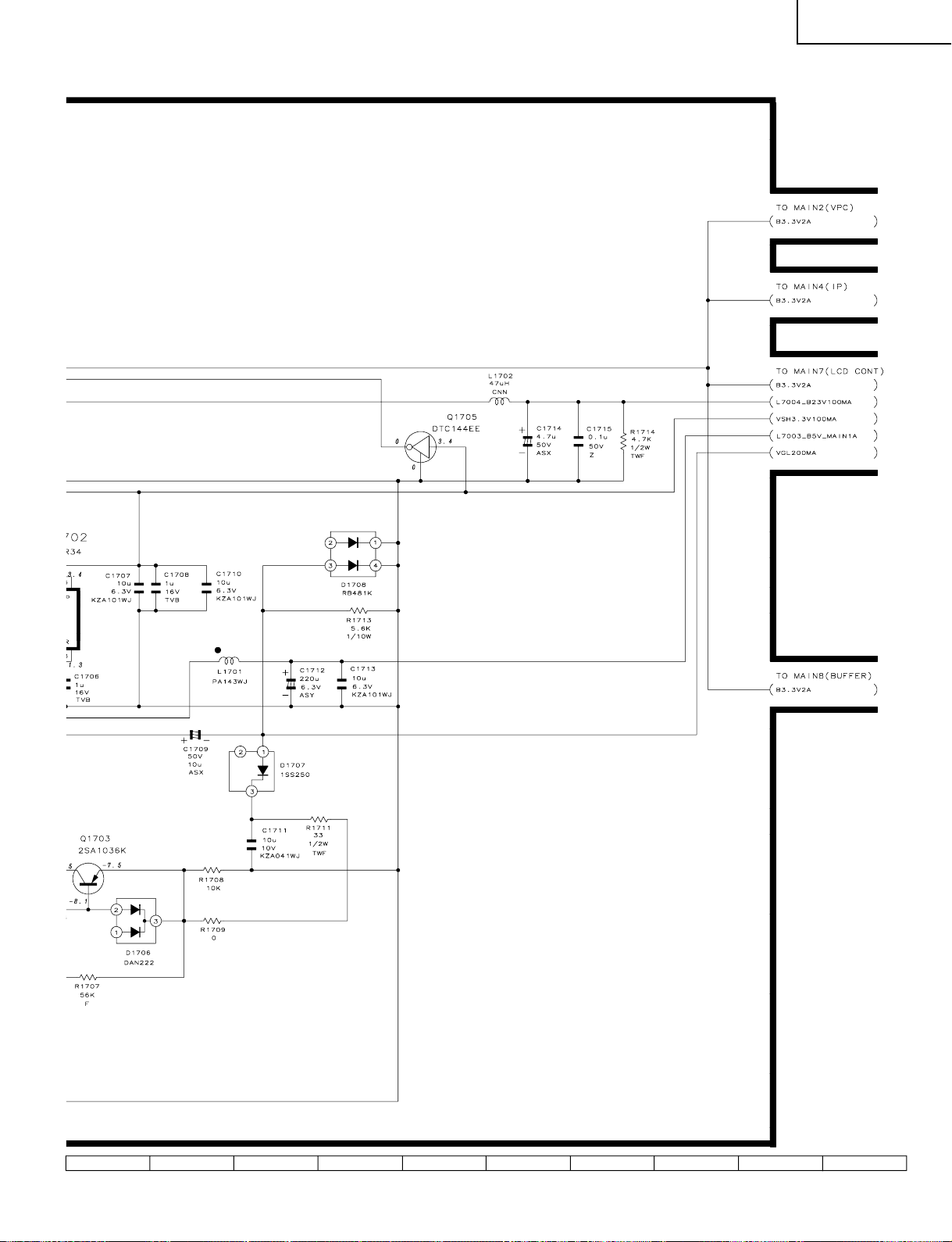
SCHEMATIC DIAGRAM
Ë
OPERATION Unit
H
G
F
LC-15PX1U
E
D
C
B
A
654321
33
Page 34

LC-15PX1U
Ë
MAIN Unit-1/14
H
G
F
E
D
C
B
A
87109654321
34
Page 35

LC-15PX1U
35
1716 1918151413121110
Page 36

LC-15PX1U
Ë
MAIN Unit-2/14
H
G
F
E
D
C
B
A
87109654321
36
Page 37

LC-15PX1U
37
1716 1918151413121110
Page 38

LC-15PX1U
Ë
MAIN Unit-3/14
H
G
F
E
D
C
B
A
87109654321
38
Page 39

LC-15PX1U
39
1716 1918151413121110
Page 40

LC-15PX1U
Ë
MAIN Unit-4/14
H
G
F
E
D
C
B
A
87109654321
40
Page 41

LC-15PX1U
41
1716 1918151413121110
Page 42

LC-15PX1U
Ë
MAIN Unit-5/14
H
G
F
E
D
C
B
A
87109654321
42
Page 43

LC-15PX1U
43
1716 1918151413121110
Page 44

LC-15PX1U
Ë
MAIN Unit-6/14
H
G
F
E
D
C
B
A
87109654321
44
Page 45
LC-15PX1U
45
1716 1918151413121110
Page 46

LC-15PX1U
Ë
MAIN Unit-7/14
H
G
F
E
D
C
B
A
87109654321
46
Page 47

LC-15PX1U
47
1716 1918151413121110
Page 48

LC-15PX1U
Ë
MAIN Unit-8/14
H
G
F
E
D
C
B
A
87109654321
48
Page 49

LC-15PX1U
49
1716 1918151413121110
Page 50

LC-15PX1U
Ë
MAIN Unit-9/14
H
G
F
E
D
C
B
A
87109654321
50
Page 51

LC-15PX1U
51
1716 1918151413121110
Page 52

LC-15PX1U
Ë
MAIN Unit-10/14
H
G
F
E
D
C
B
A
87109654321
52
Page 53

LC-15PX1U
53
1716 1918151413121110
Page 54

LC-15PX1U
Ë
MAIN Unit-11/14
H
G
F
E
D
C
B
A
87109654321
54
Page 55

LC-15PX1U
55
1716 1918151413121110
Page 56

LC-15PX1U
Ë
MAIN Unit-12/14
H
G
F
E
D
C
B
A
87109654321
56
Page 57

LC-15PX1U
57
1716 1918151413121110
Page 58

LC-15PX1U
Ë
MAIN Unit-13/14
H
G
F
E
D
C
B
A
87109654321
58
Page 59

LC-15PX1U
59
1716 1918151413121110
Page 60

LC-15PX1U
Ë
MAIN Unit-14/14
H
G
F
E
D
C
B
A
87109654321
60
Page 61

LC-15PX1U
61
1716 1918151413121110
Page 62

LC-15PX1U
Ë
ANALOG Unit-1/4
H
G
F
E
D
C
B
A
87109654321
62
Page 63

LC-15PX1U
63
1716 1918151413121110
Page 64

LC-15PX1U
Ë
ANALOG Unit-2/4
H
G
F
E
D
C
B
A
87109654321
64
Page 65

LC-15PX1U
65
1716 1918151413121110
Page 66

LC-15PX1U
Ë
ANALOG Unit-3/4
H
G
F
E
D
C
B
A
87109654321
66
Page 67

LC-15PX1U
67
1716 1918151413121110
Page 68

LC-15PX1U
Ë
ANALOG Unit-4/4
H
G
F
E
D
C
B
A
87109654321
68
Page 69

LC-15PX1U
69
1716 1918151413121110
Page 70

LC-15PX1U
Ë
R/C, LED Unit
H
G
F
E
D
C
B
A
654321
70
Page 71

LC-15PX1U
Ë
CARD LED Unit
H
G
F
E
D
C
B
A
654321
71
Page 72

LC-15PX1U
Ë
CARD DETECT Unit
H
G
F
E
D
C
B
A
654321
72
Page 73

LC-15PX1U
Ë
INVERTER Unit
H
G
F
E
D
C
B
A
654321
73
Page 74

LC-15PX1U
PRINTED WIRING BOARD ASSEMBLIES
H
G
F
E
D
C
B
C5121
C5122
C5123
C5027 C5026 C5025 C5024
C5028
IC5003 IC5102
R2091
P2005
C5124
C5029
R5121 R5119 R5125
R5004 R5003 R5016 R5011 R5010 R5006
R5129 R5130 R5128
R5017
C5004
R5066
R5065
R5133
R5012
R5024
C5023
C5011 C5012
C5120
P5601
C5022
R5118
C5112
R5025
R5001
R5116
C5020
C5115
C5119
C5110
R5028
C5021
C5018
R5023
IC5002
C5118
C5111
C5019
C5030
R5029
C5008
C5117
C5017
C5013
C5015
R5056
C5016
C5116
C5109
C5007 C5014
C5102
C5104
C5105
C5108
R5030
MAIN Unit (Side-A)
R5717
R5047
R5071
R5040
R5032
R5043 R5041
R5136
D5002
R5072
Q5001
R5062
R5051
R5063
R5064
R5067
R5049
R5034
R5713
R5712
R5033
R5714
R5052
R5219
C5222
R5733
R5735
R5737
D5003
R5218
R5201
R5202
R5220
R5732
R5734
R5736
R5203
R5729
C5207
R5748
R5751
R5731
D5702
R5217
R5229
R5747
R5204
P5201
R5730
R5222
R5228
TL5207
IC5202
IC5201
R5205
C5701
IC5704
R5206
R5740
R5742
R5744
R5227
R5728
R5216
R5050
C5211
R5045
R5752
R5226
R5215
R5739
R5741
R5743
R5210
C5713
R5749
R5214
C5218
R5212
R5211
R5738
D5703
R5225
R5224
R5223
R5209
R5750
R5754
D5604
R5213
R5207 R5208
R5608 R5609 R5610 R5611
R5619
SC5601
P5100
R5138
D5601
R5628 R5629 R5630 R5631
R5637
R5623
R5620
R5634 R5636
R5632 R5633
R5625
R5626 R5627
TP5603
R5618
R5635
R5622
C5629
R5624
R5602
R5746
C5710
R5759
R5745
TP2001
D5701
C5714
R5727
R5726
R5702
R5701
TP5602
C8605
R8622
R8602 R8620
SC1204
R8608
IC8603
IC8602
R8610
P2004
C1232
R5758
FB1204
R8613
R5757
C1226
FB1203
C1220
C1208
TP2068
FB1202
C8542
R8609
C1221
IC8503
C1229
IC1207
K1
IC8606
R8606
R8621
Q8603
R1221
TP2069
R8605
C8534
C8606
R8521
C1204
R8520
D8501
C1205
A
MAIN Unit (Chip Parts Side-A)
87109654321
74
Page 75

LC-15PX1U
C1220
C1208
TP2068
FB1202
C8542
R8609
C1221
IC8503
C1229
IC1207
K1
IC8606
R8606
R8621
Q8603
R1221
TP2069
R8605
C8534
C8606
C1204
R8521
R8520
C1205
D8501
R1255
R8515
L8501
C8537
L8502
SC1201
C8540
FB8506
C8515
C8531
IC1202
C1216
C8513
C8517
IC8504
C8525
C8508 R8514 C8511
C1207
FB8504 FB8505
C8516
C8512
C8509
R8504
X8501
R1211
C8535 C8536
FB8501
R8507
R1216
IC1204
C8507
R8505
SC1202
R8506
R1208 R1206
C8858
C8501
C1210
C8816
Q713
Q712
FB712
TP702
FB709
D712
Q724
Q725
L703
D701
L701
FB715
C742
C744
R776
C747 R763
T701
D711
Q716
Q721
D710
C773
L706
D702
C741
C743
C732
C775
FB8704
C780
R795
C735
Q714
D703
C733
TP701
C745
L704
FB713
C751
C750
D705
D708
D706
D709
D707
C761
FB708
L705
C764
FB710
P701
FB711
R8837
R8801
R1134 R1102 C1107
C1714
R8836
Q8803
D1105
R2100
R2056
R1127 R1136 R1103 R1112
R2074
R2066
R2049
Q2016
R2099
R1135
R1137
R1114
L1702
R2087
D1104
R1130
Q2007
R2061
R2076
R2080
R2072
R1113
R1138
R2062
R2083
R2082
R2075
R2079
C2014
Q2015
R2101
C1122
R2064
R1131
R2107
R2065
C2019
C1709
R2071
R2108 R2120
C2018
C1712
D2006
Q2017
Q2018
C1123
R2109
R2060
R2058
R2106 R2105
R2103
C2021
Q1705
C1711
C2027
C2020
R2057
R2111
D1107
D1106
C8524
R8517
C8522
C8521C8520R8516
C8502
C1211
L8805
IC8501
FL1201
C8808
C8836
R8513
C8504
C8503
L8804
R8833
L8806
R8503
R8834
L8807
R8502
C8831
R8835
R8518
R8501
C8828
C8806
C8505
L8808
C8811
C8840
R8519
R8818 R8822
L8803
P2006
C8506
C8829
C8510
L8802 R8817 R8824
C8830
C8514
C8827
C8518 C8519
R8819 R8826
L8801
C8826
C8832
C8834
R1117
C8849 C8857 R8866
C8804
C8839
R8861
C1116
R8810
C1119
C8850 C8855 R8865
C8837
C8807
R8807
R8860
C1117
R8812
C8851 C8854 R8863
IC1101
C8812
C8819
Q8802
R8859 C8835
R8809
IC8803
R8862 C8852 R8814
C1104
R8821 R8870
R8808
R8813
C1106
C8802
C8803
R8805
R1101
C1715
C8801 R8802 R8806
Q8801
C1105
R1714
C1102
R8804
C8825 C8820
R1116
C8722
C8818
R8803
R1711
C2016
IC2001
R2068
D1707
FL2001
C1713
R2054
TL2073
L1701
R2112
SC2001
R1708
R1709
R1712
R1710
Q1704
R2051
R2052 C2015
R2050
R2114
R1707
R2121
R1706
C2013
P2003
D1706
Q1703
R2045
X2001
C1704
R1705R1703
C1701
IC1701
R2041
R2040
R2037
R2102
R2032
C1703
C2007 C2008
C2006
R2039
C2030 C2031
TP707
TP703
R2036
R796
C2032 R2117
75
1716 1918151413121110
Page 76

LC-15PX1U
R
C
R
1
6
H
G
F
E
D
C
B
TL714
TL711
TL708
TL712
TP704
TL701
TL702
TL704
TL706
TL707
TL710
MAIN Unit (Side-B)
TL2014
TL2016
TL2013
TL2015
R2004
C2023
C2022
R2033
R2007
R2008
TL2064
R2013
C2001
C2012
R2003R2015R2025
R1701
TL2071
C2026
TL2062
R2094R2020
TL2057
TL2059
TL2072
TL2060
TL2058
D1703
IC2004
R2018
R2021
R2044
R2016R2022R2023
R2026
Q2004
Q2005
IC1702
TL2055
R2078
TL2056
TL2054
C1706
C2009
R2017
R2028
TL2053
TL2052
R2002
R2024
C2010
R2011
R2035
TL2051
TL2050
TL2017
C1710
R2009
R2104
TL2049
TL2048
C2011
R2047
R2046
Q2001
TL2047
C1707
C2004
D2001D2003
R2085
R2122
R2053
TL2045
TL2044
TL2046
Q2010
TL2043
TL2042
C1708
IC2003
R2043
R2048
TL2041
TL2040
R2012
C2002
R2086
IC2006
Q2014
R2096
R2095
R2027
TL2039
TL2038
R2069
C2024
TL2037
TL2033
TL2036
R1108
D1102
Q1104
C2003
IC2002
R2031
Q2006
R2042
R2001
TL2035
TL2034
Q1101
C2005
R2077
Q2013
TL2032
R1126C1109R1104
R2115
C2017
D2005
TL2025
TL2031
TL2028
TL2030
R2070R2059R2055
TL2027
R1713
IC2005
R2098
R2029
D1708
Q2008
C1115
R1125
R2067
R2063
TL2023
TL2029
TL2099
C1101
R2084
TL2021
D1103
C8716R8713
R8712
Q2012
TL2019
TL2026
C8719
C8712R8705C8717R8714
Q2003
R2014
Q2002
R2006
Q1106
R2019
Q1702D1705
C8711R8704C8713C8714C8718
C1702
R2005
TL2018
R1124
R1702
R2073
R8703
R1704
Q1701
C8708
C1114
Q1105
C8721
C8720
R8706
R8707
FB8703
C8707
C8709
IC8701
C8706
R8701
R8702
R8711
C8705
C8710
TL2083
TL2088
C8703
C8809
C8814
R8816
R8811
C8715
TL2086
C8704
C8810
TL2085
TL2084
FB8702
C8822C8821
C8813
C8815
C8817
C8833
C8824C8823
FB8701
C8702
C8701
R8710R8709
TL2082
R8823
TL2087
X8801
C8533
R8522
R8825
C8532
C8838
TL2063
TL2067
R8827
TL2065
IC8801
C8845
IC8502
C8541
C8530
FB8509
C8841
R8828
R8829
FB8507
C8538
C8842
TL2022
TL2061
C8528C8529
C8527
FB8508
C8539
C8526
TL2024
TL2020
C8523
R1230
R1220
R1227
R1223
R1226
R1224
R1229
R1225
R1219
R1231
C8846
C8848
R8832R8830
C8847
R8831
C8844
TL1222
TP5611
R1236C1212
TL1223
C1213
R1235
R1240
TL1224
TL1249
TP5601
TL1225
C1215
TL1226
TL1233
R1242
TL1227
R1244
TL1228
TL1237
R1248R1246
TL1229
TL1239
R1265
TL1230
TL1241
TL1202
R1251
R1249
TL1231
TL1242
TL1204
R1250
TL1243
TL1244
IC1201
TL1232
TL1245
TL1206
R1266
R1253
TL1247
FB1208
R1252
R1241
R1243
R1245
TL1208
TL1212
TL1210
FB1207
TL1221
TL1215
C1217
FB1206
R1218
R1222
R1232
R1234
TL1217
TL1219
C1218
R1239
TL1218
R1261
R1262
C1219
IC1206
TL1201
IC1205
R1260
C1224
C1225
TL121
TL12
TP705
R1756
R1750
R773
R708C711
C774
R1755
IC708
R1753
Q723
R1752
R757
R756
R780
C778
C779
R791
C727
R739C709R759
C729
Q707
C740
R774
C715R760
R753
R745
R735
R723
C703
C728
R758
C756
C701
R712
C753
R738
C721
R733
FB707
C759
C765
IC707
R788
R782
C755
R786
R752
R755
R704
C776
R706
C722
C723
R741
R714
R784
C752
R771
Q722
D720
Q706
R705
R772
C739
IC702
R748
R740
C713
R725
C705R799
R710
R734
C720
R731
R720
C767
R719
R769
Q701
R701
Q705
C738
R751
R770
IC703
R742
C710C768
R713
R722
R707
C717
C702
R727
Q702
Q709
R797
R703
Q711
R764
IC701
C736
R765
C726
R743
R732
C714
R721
C766
R726
C706
R777
R778
C769
Q719
R779
R793
C770
C763
R794
R790
C748
R789
C749
R798
Q717
R781
R711
C716
C772
R1754
C777
R1751
C771
C730
Q703
R702
IC704
C707R761
R736
R728
C725
C718
R744
R729
R715
Q704
R716
FB704
C758
FB706
FB705
C754
FB702
R749
FB703
FB714
TL709
C762
TL713
Q718
R787R785
C757R783R792C760
TP706
C2029R2116
R2118C2028
TL2070
D2004
R2113
C2025
D1701
D1702
D1704
C1705
R2010
R2038
D2002
TL2066
A
MAIN Unit (Chip Parts Side-B)
87109654321
76
Page 77

LC-15PX1U
231
1
TL1243
242
TL1244
02
L1204
IC1201
1
TL1232
TL1245
TL1206
R1266
R1253
TL1247
FB1208
R1252
R1241
R1243
R1245
TL1208
TL1212
TL1210
FB1207
TL1221
TL1215
C1217
FB1206
R1218
R1222
R1232
R1234
TL1217
TL1219
C1218
R1239
TL1218
R1261
R1262
C1219
IC1206
TL1201
IC1205
R1260
C1224
C1225
TL1216
TL1214
TL1211
C1214
R1237
R1247
R1259
C1209
R1233
TL1209
FB1205
R1267
C1230C1228
C1234
TL1295
TL1266
TL1265
R8604
Q8601
C1231
TL1267
TL1268
TL1262
TP5610
TL1269
Q8602
R8603
C8601
C8607
C1223
TL1259
IC8601
TL1270
TL1256
TL1271
R8615
TL1272
TL1273
FB8601
C8602
C8603
TL1260
TL1274
C1206
C1222
IC1208
TL1275
TL1257
TL1263
R8619
TL1276
TL1278
TL1279
TL1277
TL1264
TL1258
TP5608
TL1261
TL1280
R1257
R1256
R1258
C1233
TL1296
TL1281
TL1282
TL1284
C8604
R8618R8607
C1227
R1268R1264
TL1285
TL2094
R5755
TL2068
TP5605
R5703
TL2069
TL1283
R5756
R1263
TL2095
C5706
C5617
C5616
TL2075
IC5616
C5619
IC5615
IC5614
IC5613
IC5612
IC5617
C5618
C5620
TL2096
R5601
IC5703
C5707
TL2097
C5614
TL2077
C5601
C5627
TL2076
C5612
R5642
C5610
C5615
C5613
TL2098
IC5606
IC5608
IC5611
IC5610
C5623R5638
IC5609
IC5607
C5611
TL2078
C5624R5639
R5690
C5602
R5694
R5693
R5692
R5691
C5603
IC5618
IC5602
IC5605
IC5604
C5625R5640
IC5603
C5628
IC5601
IC5619
C5622
C5609
C5608
C5626R5641
C5605
TP5607
C5604
TL5110
C5621
C5606
C5607
TL5111
R5698
R5697
R5696
R5695
C5630
D5602
R5613R5616R5615
R5604R5607R5614
R5612
TL5112
R5621
C5631
R5617
R5603
TP5606
R5605R5606
D5603
FB5102
FB5101
Q5702
TL5206
C5704
TL5710
TL5712
R5137
C5215
C5214
TL5202
R5232
C5209
C5210
IC5702
TL5709
R5231
TL5201
TL5203
C5219
C5212
R5753
C5712
TL5701
R5230
C5221
P5701
TL5706
C5213
C5208
C5705
TL5204
Q5701
TL5705
C5223
C5204
C5702C5708
TL5205
C5220
C5224
TL5704
C5216
C5203
TL5703
C5130
TL5702
TL5109
R5221C5201
C5202
C5129
C5217
TL5003
C5205
C5206
IC5701
R5233
C5106
TL5108
TL5101
TL5102
TL5103
X5201
TL5105
C5711
R5709
TL5002
R5038R5037R5035
C5703
C5103
R5113
R5114
R5110
R5112
R5109
R5107
R5101
R5715
R5716
R5108
R5102
S5701
TL5001
R5046
R5048
C5005
R5044R5042R5039
R5054
R5111
R5104
R5031
TL5104
C5113
R5058
R5057
C5709
TL5005
IC5101
R5027
TL5004
R5115
C5001
C5006
TL5107
C5114
IC5001
R5026
C5107
X5001
R5022
R5020
R5123
R5021
TL5106
C5002
R2092
R5126
R5061
R5019
TL2079
R2093
R5124
R5127
C5009
R5134
R5018
R5015
R5007
TL2080
TL2081
R5131
R5132
C5010
TL2090
R5122
R5120R5117
C5127
R5005R5002R5014R5008R5009R5013
TP5609
R2090
C5126C5125
C5031
TL2092
TL2091
C5032
TL2089
TL2093
C5128
C5101R5135
TP5604
C5033
IC5004IC5103
C5003R5068
D5001
R5036
77
1716 1918151413121110
Page 78

LC-15PX1U
H
G
F
ANALOG Unit (Side-A)
E
D
C
B
A
87109654321
78
Page 79

LC-15PX1U
79
1716 1918151413121110
Page 80

LC-15PX1U
H
G
F
ANALOG Unit (Chip Parts Side-A)
E
D
C
B
A
J3407 J3404
J3406
D3402
R3415
R3406
R3423
Q3402 Q3401
R3424
R3401
R3544
C3413
D3401
R3438
R3439
Q3403
C3414
R3545
R3248
D3404
R3443
C3424
R3404
R3412
R3466
R3489
C3443
C3441
R3490
C3417
R3421
C3418
R3416
R3407
D3408
R3444
C3409
R3420 R3422
D3407 D3406 R3414
R3409 C3406 R3449 R3413 C3405 R3448
C3452
C3448
D3409
R3411
R3428
CF3401
D3410
R3212
C3205
C3264
C3206
R3216
R3371
C3267
C3268
R3202
IC3205
TP3432
IC3402
C3201
R3417
C3714
C3410
C3425
X3202
IC3403
D3411
R3403
C3401
D3707
R3266C3265
IC3202
R3732
R3243
C3223
C3229
C3224
C3231
FB3203
R3547
R3402
C3442
R3208
FB3202
R3249
R3418
R3227
R3265
D3201
IC3203
C3408
C3403 C3407
R3457
R3460
C3435
R3461
C3436
R3465
R3477
C3437
C3444
C3433
C3227
R3213
R3242
R3206
C3207
L3202
C3446
C3266
C3263
C3704
SLD7003
R3210
C3204
R3209
C3273
R3246
R3263
R3261
R3203
X3203
R3241
IC3209
C3203
IC3206
C3210
D3703
R7073
R7074
R7072
L7006
R3710
C7057
R3244
R3709
Q7017
FL7006
FL7005
R3215
Q3204
C3225
Q3203
R3702
R3222
R3214
C7053
P3201
R7049
C3214
R3239
R3236
Q3706
D3705
C7039
C3226
C3275
R3271
R3219
C3221
R3235
R3234
R3207
C3702
R3701
R3270
C7051
R7038
C3272
R7050
X7000
R3221
IC7006
R3272
R3223
C3217
C3333
Q3705
D3704
Q7009
C3208
C3274
R3224
C3703
C7058
C7044
C3202
IC3207
C3211
C7043
C3220
L7007
X3201
R3703
L7005
C7052
C7048
C7070
C7071
C7049
R7041
R7039
L7004
R7071
C3222
C3219
C3215
IC3208
IC3204
R3231
D3702
P3701
C7047
R3218
C3213 R3211 C3212
R3228
L3201
R3217
C7045
FB3201
R3229
C3701
C7059
R3269
C3271
C7054
C3334
C7021
C3336
C3209
R3201
C7056
C3330
C3337
C7041
C3270
R3220
Q3302
Q3301
R3355
Q3201
C7037
FB7003
R7036
C3216 C3218
C3335
R3333
IC7003
C7038
C3228
C3238
R3204
R7069
FL7004
C3230 R3226
C3233
C3366
C3331
R3354
R7070
C3338
C3234
IC3201
C3235
R3332
R7024
R3230
L3203
IC3306
IC3304
R3267
C3340
R3356
C7033
C3236
P3302
R7020
P3301
FB7002
C3232 R7027
R3347
Q3306
R3348
R3376
R7030
R7021
C3243
FB7001
R3225
R3309
C7004
C3237
Q7006
R3349
C3351
C7027
R3237
Q3305
R7033
C7028
C7032
C7031
C7030
C7029
C7026
C7025
C7024
R7015
C7018
R7010
R7009
IC7001
R7011
R3366
C3244
R3331
R3397
C7003
R3257
C3245
R3250
R3205
R3326
R3330
R3329
C7006
C7023
R7061
C3252
C3339
L7001
Q7014
C7011
R7026
C7022
C7064
R7029
R7013
C7007
R7018
C7010
R7017 C7020
D3205
SLD7002
C7005
R7019
C3261
C3262
C3308
C3364 C3309
R7065
Q7011
Q7012
D3202
R3319
R7014
Q7004
R3372 R3374
Q3303 Q3207
R7059
Q7016
Q7015
R3325 R3318 R3315
R3328
FL7003
C3306
R3375
C3307
R3373
C3365
Q7002
Q7005
R3364 C3321
C3341
P3304
C3253
C3254
C3327
R3323
R7056
FB7005
FB7004
R7058
C7069
C3329
R3255 D3204
C3332
R3367
R3335
C7063
R7063
R7064
R7062
R7028
R7025
C7001
C3305
R3314
R3256
C7062 R7003
R3303
C3304
R3304
C3323
L7003
R7066 R7068
R3369
IC3303
D3302
C3353
D3301
C3251
C7065
SLD7001
R7067
Q3417
C3355
R3351
R3350
R3308
IC3301
C3356
RY3301
C3303 R3515
C3352
C3312
R3353
R3505
C3476
D3303
R3352
R3305
D7001 FL7007 C7067
R3368
C3318
R3365
C3360
Q3415
R3514
C3325
C7035
R3307
R3398
R3336
R3517
C7068
C3311
R3311
R3321
R3320
C3465
R3511
C3328
C3310
C3301 R3302 C3302
C3347
P3303
C7036
C7034
Q3304
Q3414
IC7004
R3370 R3301 R3306
C3319
R3322
C3354
C3706
C3475
R3312
C3358
R3482
R3343
R3344
R3324
SC3403
R3509
C3431
C3447
R3504
C3469
C3349
R3474
C3429 C3479
R3491
Q3405
R3345
C3438
C3459
R3338
R3734
R3501
R3503
C3346 C3361
R3467
IC3305
C3342
L3403
C3348 C3343
R3462
L3303
C3445
R3337
R3733
R3546
C3432
C3350 R3459
R3346 R3340
Q3413
IC3404
R3468
R3473
D3309 R3339
R3469
R3470
C3359
IC3406
IC3401
D3304
R3359
R3342
R3357
C3362
C3345
L3702
R3451
C3449
Q3715
L3402
R3483
P3404
C3427
Q3406
R3502
R3358
R3341
80
87109654321
Page 81

C33
9
TP3433
R3441
C3430
D3405
D3403
R3433
R3429
C3420
LC-15PX1U
P3702
J3402
C3127
Q3110
Q3107
R3118
R3383
C3383
C3369
R3377
R3730
D3706
FH3703
R3386 C3374
R3391
C3376 R3384
R3392
P3703
C3367
C3116
C3260
C3368
Q3106
C3117
L3103
R3126
Q3109
R3119
FH3701
L3104 C3109 R3112
R3156
Q3117
R3127
D3106
C3472
D3701
C3313
D3104
R3108
IC3102
C3107
R3107
C3462
TU3401
FH3704
C3464
C3710
R3240
C3709
R3268
Q3710
R3722
R3238
C3385
R3395
R3381
R3731
R3233
R3396
Q3709
C3373
R3721 R3718
C3711
R3379
C3705
D3305
R3717 R3719
C3370
R3725
R3529
R3715
R3716
C3377
R3393
C3384
R3394
C3382
R3390
R3232
R3727
R3532
R3726
R3723
R3720
C3269
R3728
IC3701
R3388
C3371
R3361
Q3419
P3704
R3530
R3729
C3381
IC3307
R3378
Q3702 Q3701
R3385
R3519
R3387
R3362
C3375 C3713
C3380 C3379
R3380
IC3308
C3372
R3543
C3712
R3382
R3389
C3378
C3483
SC3403
R3546
R3501
R3503
Q3413
C3459
IC3404
R3474
R3468
R3462
R3467
C3438
R3491
Q3405
R3509
C3431
C3447
R3504
C3469
475
C3445
L3403
R3473
C3432
L3303
C3429 C3479
3343
3344
C3350 R3459
C3346 C3361
IC3305
4
R3345
D3309 R3339
C3348 C3343
358
R3338
C3342
R3337
R3346 R3340
6
R3734
R3733
R3469
R3470
R3359
C3359
IC3406
IC3401
D3304
R3342
R3357
C3362
C3345
L3702
R3451
C3449
Q3715
L3402
P3404
R3483
R3358
Q3406
R3341
C3427
R3502
C3363
C3344
R3452
C3473
R3434
C3428
R3510
R3508
R3499
R3500
R3453
FL3401
R3456
L3405
L3701
C3440
R3455
C3439
R3454
R3445
C3470
C3467
Q3407
C3708
R3714
C3707
R3724
Q3711
P3202
R3507 R3542
C3471
C3485
R3497
TP7000
L3401
R3431
C3419
C3484
R3427
C3458
FH3702
R3410
R3446
R3447
R3408
R3524
R3426
C3421
C3402
R3405
R3533
Q3418
J3401
R3531
R3518
J3701
81
1716 1918151413121110
Page 82

LC-15PX1U
H
G
F
E
D
C
B
A
INVERTER Unit (Side-A)
654321
82
Page 83

LC-15PX1U
H
FH6503 FH6504
G
F
R6517
R6506
C6508
R6518
Q6505
R6513
Q6503
R6507
C6507
R6504
L6502
C6504
C6511
E
Q6504
D6500
C6503
R6502
C6502
R6503
R6500
Q6502
D
R6501
C6509
L6500
T6502
FH6502
FH6501
P6501
Q6500
C6510
C
Q6501
T6500
P6500
B
P6502
A
INVERTER Unit (Chip Parts Side-A)
654321
83
Page 84

LC-15PX1U
H
OPERATION Unit (Side-A)
(QPWBXC466WJN1)
G
P4050
D4050 D4052
S4053
D4051
R4052
SW4054
R4051
SW4052
R4050
SW4051
SW4050
R4053
SW4055
SW4056
OPERATION Unit (Chip Parts Side-A)
(QPWBXC466WJN1)
F
E
R/C, LED Unit (Side-A)
(QPWBXC467WJN1)
SLD4000
D4005
R4001
D4004
D4001
R4002
Q4001
D4003
Q4004
R4004
R4003
Q4002
R4011
R4012
R4013
D4006 R4005
D4002
Q4003
C4004
R4014
C4003
J4021
C4203
P4001
D
C4202
IC4201
C4201
R4006
C4001
RMC4001
R/C, LED Unit (Chip Parts Side-A)
(QPWBXC467WJN1)
D9201
D9202
R9203
C9207 R9202
R9204
R9205
C9209
R9209
C9208
P9203
C
R9208
P9201
IC9201
C9201
R9206
R9207
R9201
C9204
IC9202
P9202
B
CARD LED Unit (Side-A)
(QPWBXC468WJN1)
CARD LED Unit (Chip Parts Side-A)
(QPWBXC468WJN1)
C9202
C9203
C9206 C9205
A
CARD DETECT Unit (Side-A)
654321
84
Page 85

LC-15PX1U
Ref. No. Part No. ★ Description Code Ref. No. Part No. ★ Description Code
P ARTS LIST
LISTE DES PIECES
P ARTS REPLACEMENT
Replacement parts which have these special safety characteristics identified in this manual ; electrical components having such features are
identified by å and shaded areas in the Replacement Parts Lists and
Schematic Diagrams. The use of a substitute replacement part which
does no have the same safety characteristic as the factory recommended
replacement parts shown in this service manual may create shock, fire
or other hazards.
"HOW TO ORDER REPLACEMENT P ARTS"
To have your order filled promptly and correctly, please furnish the following informations.
1. MODEL NUMBER 2. REF. NO.
3. PAR T NO. 4. DESCRIPTION
in USA: Contact your nearest SHARP Parts Distributor to order. For
location of SHARP Parts Distributor, Please call Toll-Free;
1-800-BE-SHARP
★ MARK: SP ARE PARTS-DELIVERY SECTION
Ref. No. Part No. ★ Description Code Ref. No. Part No. ★ Description Code
Les pi`eces de rechange qui pr élelesentent ces caract éleristiques sp
éleciales de s élecurit éle, sont identifi élees dans ce manuel : les pi`eces
élelectriques qui pr élesentent ces particularit éles, sont rep éler élee
par la marque å et sont hachur élees dans les listes de pi`eces et dans
les diagrammes sch élematiques.
La substitution d'une pi`ece de rechange par une autre qui ne pr éLesente
pas les m éoemes caract éLeristiques de s élecurit éle que la pi`ece
recommand élee parl'usine et dans ce manuel de service, peut provoquer
une éLelectrocution, un incendie ou toutautre sinistre.
"COMMENT COMMANDER LES PIECES DE RECHANGE"
Pour que votre commande soit rapidement et correctement remplie,
veuillez fournir les renseignements suivants.
1. NUMERO DU MODELE 2. NO. DE REF
3. NO. DE PIECE 4. DESCRIPTION
in CANADA: Contact SHARP Electronics of Canada Limited
★ MARQUE: SECTION LIVRAISON DES PIECES DERECHANGE
PRINTED WIRING BOARD ASSEMBLYS
(NOT REPLACEMENT ITEM)
DUNTKC351FE02 – INVERTER Unit —
DUNTKC464FE02 – MAIN Unit —
DUNTKC465DE02 – ANALOG Unit —
DUNTKC466DE02 – OPERATION Unit —
DUNTKC467DE02 – R/C, LED Unit —
DUNTKC468DE02 – CARD LED Unit —
DUNTKC469DE02 – CARD DETECT Unit —
Q6500 VS2SC5886++-1Y J 2SC5886 AE
Q6501 VS2SC5886++-1Y J 2SC5886 AE
Q6502 VS2SA1530AR-1Y J 2SA1530AR AB
Q6503 VS2SC5886++-1Y J 2SC5886 AE
Q6504 VS2SC5886++-1Y J 2SC5886 AE
Q6505 VS2SA1530AR-1Y J 2SA1530AR AB
CHANGE DES PIECES
Phone (416) 890-2100
DUNTKC351FE02
INVERTER Unit
TRANSISTORS
LCD PANEL
NOTE: THE PARTS HERES SHOWN ARE SUPPLIED AS AN
ASSEMBLY BUT NOT INDEPENDENTLY.
RLCDTA024WJZZ J 15" LCD Panel Unit CT
D6500 VHDDAN222//-1Y J Diode AA
DIODE
COILS
L6500 RCiLPA093WJZZ J Coil AF
L6502 RCiLPA093WJZZ J Coil AF
TRANSFORMERS
å T6500 RTRNZA033WJZZQ J Transformer AQ
å T6502 RTRNZA033WJZZQ J Transformer AQ
CAPACITORS
C6502 VCKYCY1CB104KY J 0.1 16V Ceramic AB
C6503 VCKYCY1CB333KY J 0.033 16V Ceramic AA
C6504 RC-EZA216WJZZ J 1000 16V Electrolytic AD
C6507 VCKYCY1CB104KY J 0.1 16V Ceramic AB
C6508 VCKYCY1CB333KY J 0.033 16V Ceramic AA
C6509 RC-EZA216WJZZ J 1000 16V Electrolytic AD
C6510 RC-FZA107WJZZ J 0.1 250V Film AD
C6511 RC-FZA107WJZZ J 0.1 250V Film AD
RESISTORS
R6500 VRS-TW2ED182JY J 1.8k 1/4W Metal Oxide AA
R6501 VRS-TW2ED152JY J 1.5k 1/4W Metal Oxide AB
R6502 VRS-CY1JF103JY J 10k 1/16W Metal Oxide AA
R6503 VRS-CY1JF333JY J 33k 1/16W Metal Oxide AA
R6504 VRS-TW2ED182JY J 1.8k 1/4W Metal Oxide AA
R6506 VRS-CY1JF103JY J 10k 1/16W Metal Oxide AA
R6507 VRS-CY1JF333JY J 33k 1/16W Metal Oxide AA
R6513 VRS-TW2ED152JY J 1.5k 1/4W Metal Oxide AB
MISCELLANEOUS PARTS
å F6501 QFS-D0006CEZZ J Fuse, 1.25A/250V AF
å F6502 QFS-D0006CEZZ J Fuse, 1.25A/250V AF
85
Page 86

LC-15PX1U
Ref. No. Part No. ★ Description Code Ref. No. Part No. ★ Description Code
DUNTKC351FE02
INVERTER Unit (Continued)
FH6501 QFSHD1002CEZZ J Fuse Holder AA
FH6502 QFSHD1002CEZZ J Fuse Holder AA
FH6503 QFSHD1002CEZZ J Fuse Holder AA
FH6504 QFSHD1002CEZZ J Fuse Holder AA
P6500 QPLGN0155FJZZY J Plug, 3-pin AE
P6501 QPLGN0155FJZZY J Plug, 3-pin AE
P6502 QPLGN0378GEZZ J Plug, 3-pin AB
QCNW-B930WJQZ J Connecting Cord AF
DUNTKC464FE02
MAIN Unit
INTEGRATED CIRCUITS
IC701 RH-iXA828WJZZY J BD9300FV-FE2 AH
IC702 RH-iXA828WJZZY J BD9300FV-FE2 AH
IC703 RH-iXA828WJZZY J BD9300FV-FE2 AH
IC704 RH-iXA828WJZZY J BD9300FV-FE2 AH
IC707 RH-iXA828WJZZY J BD9300FV-FE2 AH
IC708 RH-iXA828WJZZY J BD9300FV-FE2 AH
IC1101 VHiBD8120FP-1Y J BD8120FP AX
IC1201 RH-iXA595WJZZQ J LR38853 BC
IC1202 VHiiCS570B+-1Y J ICS570BT AQ
IC1204 VHiNC7SV04+-1Y J NC7SV04P5X AD
IC1701 VHiNJM2147M-1Y J NJM2147M-TE1 AF
IC1702 VHiPQ1R34++-1Y J PQ1R34 AE
IC2001 RH-iXA621WJN1Q J M306V7FHFP BM
IC2002 VHiPQ1L333M-1Y J PQ1L333M2SP AD
IC2003 VHiBD4729G+-1Y J BD4729G-TR AD
IC2004 VHiPQ20VZ11-1Y J PQ20VZ11 AG
IC2005 VHiBR2416E2-1Y J BR24C16F AK
IC2006 VHiTC4W66F/-1Y J TC4W66F AE
IC5001 RH-iXA805WJZZQ J TMS320DM270GHK BG
IC5002 RH-iXA997WJZZQ J I.C. BG
IC5003 RH-iXB074WJZZQ J K4S561632E-UC7 BA
IC5004 RH-iXB074WJZZQ J K4S561632E-UC7 BA
IC5101 RH-iXA805WJZZQ J TMS320DM270GHK BG
IC5102 RH-iXB073WJZZQ J K4S281632F-UC7 AY
IC5103 RH-iXB073WJZZQ J K4S281632F-UC7 AY
IC5201 RH-iXA420WJZZQ J TMS320DA150GGU BE
IC5202 RH-iXA420WJZZQ J TMS320DA150GGU BE
IC5601 VHiLVC245A/-1Y J SN74LVC245APW AE
IC5602 VHiLVC245A/-1Y J SN74LVC245APW AE
IC5603 VHiLVC245A/-1Y J SN74LVC245APW AE
IC5604 VHiLVC245A/-1Y J SN74LVC245APW AE
IC5605 VHiLVC245A/-1Y J SN74LVC245APW AE
IC5606 VHiLVC245A/-1Y J SN74LVC245APW AE
IC5607 VHiLVC245A/-1Y J SN74LVC245APW AE
IC5608 VHiLVC245A/-1Y J SN74LVC245APW AE
IC5609 VHiLVC245A/-1Y J SN74LVC245APW AE
IC5610 VHiLVC245A/-1Y J SN74LVC245APW AE
IC5611 VHiLVC245A/-1Y J SN74LVC245APW AE
IC5612 VHiLVC32APW-1Y J SN74LVC32APWR AF
IC5613 VHiLVC08AT+-1Y J SN74LVC08APWR AF
IC5614 VHiLVC32APW-1Y J SN74LVC32APWR AF
IC5615 VHiLVC04AT+-1Y J SN74LVC04APWR AE
IC5616 VHiLVC32APW-1Y J SN74LVC32APWR AF
IC5617 VHiLVC08AT+-1Y J SN74LVC08APWR AF
IC5618 VHiLVC244T+-1Y J SN74LVC244APWR AF
IC5701 VHiPQ20WZ11-1Y J PQ20WZ1U AF
IC5702 VHiPQ20WZ11-1Y J PQ20WZ1U AF
IC5703 VHiPQ015YZ1-1Y J PQ015YZ01ZPH AF
IC5704 VHiLVC04AT+-1Y J SN74LVC04APWR AE
IC8501 RH-iXA801WJZZQ J FLi2310-LF-BD BF
IC8502 RH-iXB029WJZZQ J MT48LC2M32B2P6 AX
IC8503 VHiPQ070XZ1-1Y J PQ070XZ01ZP AF
IC8504 VHiTC7W74U/-1Y J TC7W74FU AD
IC8601 VHiNC7WZ125-1Y J NC7WZ125 AD
IC8602 VHiTAC541FT-1Y J TC74AC541FT AL
IC8606 VHiLCX244MT-1Y J 74LCX244 AE
IC8701 VHiAD9883A1-1Q J AD9883AKST-110 BD
IC8801 VHiVPC3230D1EQ J VPC3230D-QA-B3 BD
IC8803 VHiBA7046F/-1Y J BA7046F AF
Q704 VSDTC144EKA-1Y J DTC144EKA AB
Q705 VSUML2N++++-1Y J UML2N AC
Q706 VSUML2N++++-1Y J UML2N AC
Q707 VSUML2N++++-1Y J UML2N AC
Q709 VSUML1N++++-1Y J UML1N AC
Q711 VSUML2N++++-1Y J UML2N AC
Q712 VSRTQ035P02-1Y J RTQ035P02 AD
Q713 VSRTQ035P02-1Y J RTQ035P02 AD
Q714 VSRTQ035P02-1Y J RTQ035P02 AD
86
TRANSISTORS
Page 87

LC-15PX1U
Ref. No. Part No. ★ Description Code Ref. No. Part No. ★ Description Code
DUNTKC464FE02
MAIN Unit (Continued)
Q716 VSRHP020N06-1Y J RHP020N06 AD
Q718 VSDTC144EKA-1Y J DTC144EKA AB
Q719 VSUML2N++++-1Y J UML2N AC
Q721 VSRTQ035P02-1Y J RTQ035P02 AD
Q724 VSUML2N++++-1Y J UML2N AC
Q725 VSRTQ035P02-1Y J RTQ035P02 AD
Q1101 VSFMMT718//-1Y J FMMT718 AE
Q1104 VSDTC144EE/-1Y J DTC144EE AA
Q1105 VS2SC5566++-1Y J 2SC5566 AD
Q1106 VS2SA2013++-1Y J 2SA2013 AD
Q1701 VS2SA1037KQ-1Y J 2SA1037KQ AA
Q1702 VSDTC144EE/-1Y J DTC144EE AA
Q1703 VS2SA1036K/-1Y J 2SA1036K AC
Q1705 VSDTC144EE/-1Y J DTC144EE AA
Q2002 VS2SA1037KQ-1Y J 2SA1037KQ AA
Q2003 VSDTC144EE/-1Y J DTC144EE AA
Q2004 VS2SC3928AR-1Y J 2SC3928AR AB
Q2005 VSDTC144EE/-1Y J DTC144EE AA
Q2006 VSDTC114EE/-1Y J DTC114EE AB
Q2007 VSUPA606T//-1Y J UPA606T AD
Q2008 VSDTC144EE/-1Y J DTC144EE AA
Q2010 VSDTC114EE/-1Y J DTC114EE AB
Q2012 VSUMG9N++++-1Y J UMG9N AB
Q2013 VSUMG9N++++-1Y J UMG9N AB
Q2014 VS2SC3928AR-1Y J 2SC3928AR AB
Q5001 VSUPA606T//-1Y J UPA606T AD
Q5701 VSDTC144EKA-1Y J DTC144EKA AB
Q5702 VSDTC144EKA-1Y J DTC144EKA AB
Q8601 VSDTC143ZE/-1Y J DTC143ZE AB
Q8602 VSFMMT718//-1Y J FMMT718 AE
Q8603 VSDTC144EE/-1Y J DTC144EE AA
Q8801 VS2SA1989R/-1Y J 2SA1989R AB
Q8802 VS2SC5384C/-1Y J 2SC5384C AB
DIODES
D701 VHDRB051L40-1Y J Diode AD
D702 VHDRB051L40-1Y J Diode AD
D703 VHDRB051L40-1Y J Diode AD
D705 VHDRF071M2S-1Y J Diode AD
D706 VHDRB160M40-1Y J Diode AC
D707 VHD1SS355//-1Y J Diode AB
D708 VHDRB160M40-1Y J Diode AC
D709 VHDRB160M40-1Y J Diode AC
D710 VHDRB051L40-1Y J Diode AD
D711 VHDSFPB56//2EY J Diode AC
D712 VHDRB051L40-1Y J Diode AD
D720 VHDDAN222//-1Y J Diode AA
D1102 VHDDAN222//-1Y J Diode AA
D1103 VHD1SS250//1EY J Diode AB
D1104 VHD1SS250//1EY J Diode AB
D1105 VHD1SS250//1EY J Diode AB
D1106 VHD1SS250//1EY J Diode AB
D1107 VHD1SS250//1EY J Diode AB
D1701 VHDDAN222//-1Y J Diode AA
D1702 RH-EX1224CEZZY J Zener Diode, 2V AB
D1703 VHDDAN222//-1Y J Diode AA
D1704 RH-EX1224CEZZY J Zener Diode, 2V AB
D1705 VHDDAN222//-1Y J Diode AA
D1706 VHDDAN222//-1Y J Diode AA
D1707 VHD1SS250//1EY J Diode AB
D1708 VHDRB481K++-1Y J Diode AD
D2001 VHDDAN202K/-1Y J Diode AB
D2002 RH-EX1396CEZZY J Zener Diode, 6.8V AB
D2003 VHDRB491D++-1Y J Diode AD
D2005 VHDDAN222//-1Y J Diode AA
D5002 RH-EX1244CEZZY J Zener Diode, 5.1V AB
D5003 RH-EX1244CEZZY J Zener Diode, 5.1V AB
D5601 RH-EX1244CEZZY J Zener Diode, 5.1V AB
D5602 RH-EX1244CEZZY J Zener Diode, 5.1V AB
D5603 RH-EX1244CEZZY J Zener Diode, 5.1V AB
D5604 RH-EX1244CEZZY J Zener Diode, 5.1V AB
D5701 VHDDAN222//-1Y J Diode AA
D5702 VHDDAN222//-1Y J Diode AA
D5703 VHDDAN222//-1Y J Diode AA
D8501 VHDDAN202K/-1Y J Diode AB
P ACKAGED CIRCUITS
X2001 RCRSC0032TAZZY J Crystal AG
X5001 RCRUAA008WJZZY J Crystal, 27.0MHz AM
X5201 RCRSC0186TAZZY J Crystal, 16.340MHz AK
X8501 RCRSC0193TAZZY J Crystal AH
X8801 RCRSC0012CEZZY J Crystal AH
FIL TERS AND COILS
FL1201 RFiLN0097GEZZY J Filter AF
FL2001 RFiLZA003WJPZY J Filter AD
L701 RCiLPA154WJZZY J Coil AE
L703 RCiLPA154WJZZY J Coil AE
L704 RCiLPA154WJZZY J Coil AE
L705 RCiLPA154WJZZY J Coil AE
L706 RCiLPA154WJZZY J Coil AE
L1701 RCiLPA143WJZZY J Coil AD
L1702 VPCNN470J5R4NY J Peaking 47µH AB
L8501 VPCNN5R6J1R2NY J Peaking 5.6µH AB
L8502 VPCNN5R6J1R2NY J Peaking 5.6µH AB
L8801 VP-9N3R3KR46NY J Peaking 3.3µH AC
L8802 VP-9N3R3KR46NY J Peaking 3.3µH AC
L8803 VP-9N3R3KR46NY J Peaking 3.3µH AC
L8804 RCiLPA143WJZZY J Coil AD
L8805 RCiLPA143WJZZY J Coil AD
TRANSFORMER
T701 RTRNWA120WJZZYJ Transformer AG
CAPACITORS
C701 VCKYCY1EF104ZY J 0.1 25V Ceramic AA
C702 VCKYCY1EB333KY J 0.033 25V Ceramic AA
C703 VCKYCY1EB333KY J 0.033 25V Ceramic AA
C705 VCKYCY1EB333KY J 0.033 25V Ceramic AA
C706 VCKYCY1EB333KY J 0.033 25V Ceramic AA
C710 VCCCCY1HH102JY J 1000p 50V Ceramic AB
C711 VCCCCY1HH102JY J 1000p 50V Ceramic AB
C713 VCCCCY1HH331JY J 330p 50V Ceramic AA
C714 VCKYCY1HB332KY J 3300p 50V Ceramic AA
C716 VCCCCY1HH330JY J 33p 50V Ceramic AA
C721 VCCCCY1HH330JY J 33p 50V Ceramic AA
C722 VCCCCY1HH101JY J 100p 50V Ceramic AA
C723 VCCCCY1HH101JY J 100p 50V Ceramic AA
C725 VCCCCY1HH101JY J 100p 50V Ceramic AA
C726 VCCCCY1HH181JY J 180p 50V Ceramic AA
C727 VCKYCY1HB123KY J 0.012 50V Ceramic AA
C728 VCKYCY1CB104KY J 0.1 16V Ceramic AB
C729 VCKYCY1HB123KY J 0.012 50V Ceramic AA
C730 VCKYCY1HB123KY J 0.012 50V Ceramic AA
C732 RC-KZA109WJZZY J 10 16V Ceramic AC
C733 RC-KZA109WJZZY J 10 16V Ceramic AC
C735 RC-KZA109WJZZY J 10 16V Ceramic AC
C736 VCCCCY1HH102JY J 1000p 50V Ceramic AB
C738 VCCCCY1HH102JY J 1000p 50V Ceramic AB
C739 VCCCCY1HH102JY J 1000p 50V Ceramic AB
C740 VCCCCY1HH102JY J 1000p 50V Ceramic AB
C741 RC-KZA108WJZZY J 10 10V Ceramic AC
C742 RC-KZA101WJZZY J 10 6.3V Ceramic AC
C743 RC-KZA108WJZZY J 10 10V Ceramic AC
C744 RC-KZA101WJZZY J 10 6.3V Ceramic AC
C745 RC-KZA108WJZZY J 10 10V Ceramic AC
C747 RC-KZA109WJZZY J 10 16V Ceramic AC
C748 VCKYCY1EB333KY J 0.033 25V Ceramic AA
C750 RC-KZ0072TAZZY J 1 25V Ceramic AC
C751 RC-KZ0072TAZZY J 1 25V Ceramic AC
C752 VCCCCY1HH102JY J 1000p 50V Ceramic AB
C753 RC-KZA101WJZZY J 10 6.3V Ceramic AC
C754 RC-KZA101WJZZY J 10 6.3V Ceramic AC
C756 RC-KZA109WJZZY J 10 16V Ceramic AC
C757 VCCCCY1HH101JY J 100p 50V Ceramic AA
C758 RC-KZA109WJZZY J 10 16V Ceramic AC
C759 RC-KZA041WJZZY J 10 10V Ceramic AC
87
Page 88

LC-15PX1U
Ref. No. Part No. ★ Description Code Ref. No. Part No. ★ Description Code
DUNTKC464FE02
MAIN Unit (Continued)
C760 RC-KZA041WJZZY J 10 10V Ceramic AC
C761 RC-KZA109WJZZY J 10 16V Ceramic AC
C762 VCKYCY1HB123KY J 0.012 50V Ceramic AA
C763 VCCCCY1HH102JY J 1000p 50V Ceramic AB
C764 RC-KZA108WJZZY J 10 10V Ceramic AC
C765 RC-KZA109WJZZY J 10 16V Ceramic AC
C766 VCKYCY1HB562KY J 5600p 50V Ceramic AA
C771 VCCCCY1HH101JY J 100p 50V Ceramic AA
C772 VCKYCY1HB123KY J 0.012 50V Ceramic AA
C773 RC-KZA109WJZZY J 10 16V Ceramic AC
C774 VCCCCY1HH102JY J 1000p 50V Ceramic AB
C775 RC-KZA101WJZZY J 10 6.3V Ceramic AC
C776 VCCCCY1HH102JY J 1000p 50V Ceramic AB
C779 VCKYCY1EB333KY J 0.033 25V Ceramic AA
C780 RC-KZA101WJZZY J 10 6.3V Ceramic AC
C1101 RC-KZA041WJZZY J 10 10V Ceramic AC
C1102 VCKYCY1EF104ZY J 0.1 25V Ceramic AA
C1104 RC-KZA101WJZZY J 10 6.3V Ceramic AC
C1106 RC-KZA041WJZZY J 10 10V Ceramic AC
C1107 VCCCCY1HH560JY J 56p 50V Ceramic AB
C1109 VCKYCY1EF104ZY J 0.1 25V Ceramic AA
C1114 VCKYTV1CB105KY J 1 16V Ceramic AC
C1115 VCKYTV1CB105KY J 1 16V Ceramic AC
C1116 VCKYCY1EF104ZY J 0.1 25V Ceramic AA
C1117 RC-KZA041WJZZY J 10 10V Ceramic AC
C1119 VCAAPD0JJ476MY J 47 6.3V Electrolytic AE
C1122 VCKYTV1EB104KY J 0.1 25V Ceramic AB
C1204 VCKYCY1HB103KY J 0.01 50V Ceramic AA
C1205 VCKYTV1CF105ZY J 1 16V Ceramic AB
C1207 VCKYCY1EF104ZY J 0.1 25V Ceramic AA
C1211 RC-KZA101WJZZY J 10 6.3V Ceramic AC
C1212 VCKYCY1EF104ZY J 0.1 25V Ceramic AA
C1213 VCKYCY1EF104ZY J 0.1 25V Ceramic AA
C1215 VCKYCY1EF104ZY J 0.1 25V Ceramic AA
C1216 VCKYCY1EF104ZY J 0.1 25V Ceramic AA
C1217 VCKYCY1EF104ZY J 0.1 25V Ceramic AA
C1218 VCKYCY1EF104ZY J 0.1 25V Ceramic AA
C1219 VCKYCY1EF104ZY J 0.1 25V Ceramic AA
C1224 VCKYCY1EF104ZY J 0.1 25V Ceramic AA
C1225 VCKYCY1EF104ZY J 0.1 25V Ceramic AA
C1228 VCKYCY1EF104ZY J 0.1 25V Ceramic AA
C1229 VCKYCY1EF104ZY J 0.1 25V Ceramic AA
C1230 VCKYCY1EF104ZY J 0.1 25V Ceramic AA
C1701 VCKYCY1EF104ZY J 0.1 25V Ceramic AA
C1702 VCKYCY1EF104ZY J 0.1 25V Ceramic AA
C1703 VCKYCY1EF104ZY J 0.1 25V Ceramic AA
C1704 VCEASY1CN337MY J 330 16V Electrolytic AD
C1705 VCKYTV1CB105KY J 1 16V Ceramic AC
C1706 VCKYTV1CB105KY J 1 16V Ceramic AC
C1707 RC-KZA101WJZZY J 10 6.3V Ceramic AC
C1708 VCKYTV1CB105KY J 1 16V Ceramic AC
C1709 VCEASX1HN106MY J 10 50V Electrolytic AC
C1710 RC-KZA101WJZZY J 10 6.3V Ceramic AC
C1711 RC-KZA041WJZZY J 10 10V Ceramic AC
C1712 VCEASY0JN227MY J 220 6.3V Electrolytic AC
C1713 RC-KZA101WJZZY J 10 6.3V Ceramic AC
C1714 VCEASX1HN475MY J 4.7 50V Electrolytic AC
C1715 VCKYCY1HF104ZY J 0.1 50V Ceramic AA
C2001 VCKYTV1CF105ZY J 1 16V Ceramic AB
C2002 VCKYCY1EF104ZY J 0.1 25V Ceramic AA
C2003 VCKYCY1EF104ZY J 0.1 25V Ceramic AA
C2004 RC-KZA101WJZZY J 10 6.3V Ceramic AC
C2005 RC-KZA101WJZZY J 10 6.3V Ceramic AC
C2006 VCKYCY1CB104KY J 0.1 16V Ceramic AB
C2007 VCKYCY1EF104ZY J 0.1 25V Ceramic AA
C2008 VCCCCY1EH561JY J 560p 25V Ceramic AB
C2009 VCKYCY1HB102KY J 1000p 50V Ceramic AA
C2010 VCCCCY1HH221JY J 220p 50V Ceramic AA
C2011 VCKYTV1CF684ZY J 0.68 16V Ceramic AB
C2012 VCKYCY1AB105KY J 1 10V Ceramic AB
C2013 VCCCCY1HH5R0CY J 5p 50V Ceramic AA
C2014 VCKYCY1EF104ZY J 0.1 25V Ceramic AA
C2015 VCCCCY1HH180JY J 18p 50V Ceramic AA
C2016 VCKYCY1EF104ZY J 0.1 25V Ceramic AA
C2017 VCKYCY1EF104ZY J 0.1 25V Ceramic AA
C2018 VCKYCY1EF104ZY J 0.1 25V Ceramic AA
C2020 RC-KZA101WJZZY J 10 6.3V Ceramic AC
C2022 VCKYCY1HB222KY J 2200p 50V Ceramic AA
C2023 VCKYCY1HB222KY J 2200p 50V Ceramic AA
C2024 VCKYCY1EF104ZY J 0.1 25V Ceramic AA
C2027 VCEASX0JN476MY J 47 6.3V Electrolytic AC
C2028 VCKYCY1CB104KY J 0.1 16V Ceramic AB
C2029 VCCCCY1EH561JY J 560p 25V Ceramic AB
C2030 VCKYCY1HB102KY J 1000p 50V Ceramic AA
C2031 VCCCCY1HH221JY J 220p 50V Ceramic AA
C2032 VCKYCY1AB105KY J 1 10V Ceramic AB
C5001 VCKYCY1HF104ZY J 0.1 50V Ceramic AA
C5002 VCKYCY1HB682KY J 6800p 50V Ceramic AA
C5003 VCKYCY1HB682KY J 6800p 50V Ceramic AA
C5004 VCKYCY1EF104ZY J 0.1 25V Ceramic AA
C5005 RC-KZA041WJZZY J 10 10V Ceramic AC
C5006 RC-KZA041WJZZY J 10 10V Ceramic AC
C5007 VCKYCY1EF104ZY J 0.1 25V Ceramic AA
C5008 VCKYCY1EF104ZY J 0.1 25V Ceramic AA
C5009 RC-KZA041WJZZY J 10 10V Ceramic AC
C5010 RC-KZA041WJZZY J 10 10V Ceramic AC
C5011 VCKYCY1EF104ZY J 0.1 25V Ceramic AA
C5012 VCKYCY1EF104ZY J 0.1 25V Ceramic AA
C5013 VCKYCY1EF104ZY J 0.1 25V Ceramic AA
C5014 VCKYCY1EF104ZY J 0.1 25V Ceramic AA
C5015 VCKYCY1EF104ZY J 0.1 25V Ceramic AA
C5016 VCKYCY1EF104ZY J 0.1 25V Ceramic AA
C5017 VCKYCY1EF104ZY J 0.1 25V Ceramic AA
C5018 VCKYCY1EF104ZY J 0.1 25V Ceramic AA
C5019 VCKYCY1EF104ZY J 0.1 25V Ceramic AA
C5020 VCKYCY1EF104ZY J 0.1 25V Ceramic AA
C5021 VCKYCY1EF104ZY J 0.1 25V Ceramic AA
C5022 VCKYCY1EF104ZY J 0.1 25V Ceramic AA
C5023 VCKYCY1EF104ZY J 0.1 25V Ceramic AA
C5024 VCKYCY1EF104ZY J 0.1 25V Ceramic AA
C5025 VCKYCY1EF104ZY J 0.1 25V Ceramic AA
C5026 VCKYCY1EF104ZY J 0.1 25V Ceramic AA
C5027 VCKYCY1EF104ZY J 0.1 25V Ceramic AA
C5028 VCKYCY1EF104ZY J 0.1 25V Ceramic AA
C5029 VCKYCY1EF104ZY J 0.1 25V Ceramic AA
C5030 VCKYCY1EF104ZY J 0.1 25V Ceramic AA
C5031 VCKYCY1EF104ZY J 0.1 25V Ceramic AA
C5032 VCKYCY1EF104ZY J 0.1 25V Ceramic AA
C5033 VCKYCY1EF104ZY J 0.1 25V Ceramic AA
C5101 VCKYCY1HB682KY J 6800p 50V Ceramic AA
C5102 VCKYCY1EF104ZY J 0.1 25V Ceramic AA
C5103 VCKYCY1EF104ZY J 0.1 25V Ceramic AA
C5104 VCKYCY1EF104ZY J 0.1 25V Ceramic AA
C5105 VCKYCY1EF104ZY J 0.1 25V Ceramic AA
C5106 RC-KZA041WJZZY J 10 10V Ceramic AC
C5107 RC-KZA041WJZZY J 10 10V Ceramic AC
C5108 VCKYCY1EF104ZY J 0.1 25V Ceramic AA
C5109 VCKYCY1EF104ZY J 0.1 25V Ceramic AA
C5110 VCKYCY1EF104ZY J 0.1 25V Ceramic AA
C5111 VCKYCY1EF104ZY J 0.1 25V Ceramic AA
C5112 VCKYCY1EF104ZY J 0.1 25V Ceramic AA
C5113 RC-KZA041WJZZY J 10 10V Ceramic AC
C5114 RC-KZA041WJZZY J 10 10V Ceramic AC
C5115 VCKYCY1EF104ZY J 0.1 25V Ceramic AA
C5116 VCKYCY1EF104ZY J 0.1 25V Ceramic AA
C5117 VCKYCY1EF104ZY J 0.1 25V Ceramic AA
C5118 VCKYCY1EF104ZY J 0.1 25V Ceramic AA
C5119 VCKYCY1EF104ZY J 0.1 25V Ceramic AA
C5120 VCKYCY1EF104ZY J 0.1 25V Ceramic AA
C5121 VCKYCY1EF104ZY J 0.1 25V Ceramic AA
C5122 VCKYCY1EF104ZY J 0.1 25V Ceramic AA
C5123 VCKYCY1EF104ZY J 0.1 25V Ceramic AA
C5124 VCKYCY1EF104ZY J 0.1 25V Ceramic AA
C5125 VCKYCY1EF104ZY J 0.1 25V Ceramic AA
C5126 VCKYCY1EF104ZY J 0.1 25V Ceramic AA
C5127 VCKYCY1EF104ZY J 0.1 25V Ceramic AA
88
Page 89

LC-15PX1U
Ref. No. Part No. ★ Description Code Ref. No. Part No. ★ Description Code
DUNTKC464FE02
MAIN Unit (Continued)
C5128 VCKYCY1EF104ZY J 0.1 25V Ceramic AA
C5129 VCCCCY1HH101JY J 100p 50V Ceramic AA
C5130 VCCCCY1HH101JY J 100p 50V Ceramic AA
C5201 VCCCCY1HH6R0DY J 6p 50V Ceramic AA
C5202 VCCCCY1HH6R0DY J 6p 50V Ceramic AA
C5203 VCKYCY1EF104ZY J 0.1 25V Ceramic AA
C5204 VCKYCY1EF104ZY J 0.1 25V Ceramic AA
C5205 RC-KZA041WJZZY J 10 10V Ceramic AC
C5206 RC-KZA041WJZZY J 10 10V Ceramic AC
C5207 VCKYCY1EF104ZY J 0.1 25V Ceramic AA
C5208 VCKYCY1EF104ZY J 0.1 25V Ceramic AA
C5209 VCKYCY1EF104ZY J 0.1 25V Ceramic AA
C5210 VCKYCY1EF104ZY J 0.1 25V Ceramic AA
C5211 VCKYCY1EF104ZY J 0.1 25V Ceramic AA
C5212 VCKYCY1EF104ZY J 0.1 25V Ceramic AA
C5213 VCKYCY1EF104ZY J 0.1 25V Ceramic AA
C5214 VCKYCY1EF104ZY J 0.1 25V Ceramic AA
C5215 VCKYCY1EF104ZY J 0.1 25V Ceramic AA
C5216 RC-KZA041WJZZY J 10 10V Ceramic AC
C5217 RC-KZA041WJZZY J 10 10V Ceramic AC
C5218 VCKYCY1EF104ZY J 0.1 25V Ceramic AA
C5219 VCKYCY1EF104ZY J 0.1 25V Ceramic AA
C5220 VCKYCY1EF104ZY J 0.1 25V Ceramic AA
C5221 VCKYCY1EF104ZY J 0.1 25V Ceramic AA
C5222 VCKYCY1EF104ZY J 0.1 25V Ceramic AA
C5223 VCKYCY1EF104ZY J 0.1 25V Ceramic AA
C5224 VCKYCY1EF104ZY J 0.1 25V Ceramic AA
C5601 RC-KZA041WJZZY J 10 10V Ceramic AC
C5602 RC-KZA041WJZZY J 10 10V Ceramic AC
C5603 RC-KZA041WJZZY J 10 10V Ceramic AC
C5604 RC-KZA041WJZZY J 10 10V Ceramic AC
C5605 VCKYCY1EF104ZY J 0.1 25V Ceramic AA
C5606 VCKYCY1EF104ZY J 0.1 25V Ceramic AA
C5607 VCKYCY1EF104ZY J 0.1 25V Ceramic AA
C5608 VCKYCY1EF104ZY J 0.1 25V Ceramic AA
C5609 VCKYCY1EF104ZY J 0.1 25V Ceramic AA
C5610 VCKYCY1EF104ZY J 0.1 25V Ceramic AA
C5611 VCKYCY1EF104ZY J 0.1 25V Ceramic AA
C5612 VCKYCY1EF104ZY J 0.1 25V Ceramic AA
C5613 VCKYCY1EF104ZY J 0.1 25V Ceramic AA
C5614 VCKYCY1EF104ZY J 0.1 25V Ceramic AA
C5615 VCKYCY1EF104ZY J 0.1 25V Ceramic AA
C5616 VCKYCY1EF104ZY J 0.1 25V Ceramic AA
C5617 VCKYCY1EF104ZY J 0.1 25V Ceramic AA
C5618 VCKYCY1EF104ZY J 0.1 25V Ceramic AA
C5619 VCKYCY1EF104ZY J 0.1 25V Ceramic AA
C5620 VCKYCY1EF104ZY J 0.1 25V Ceramic AA
C5621 VCKYCY1EF104ZY J 0.1 25V Ceramic AA
C5622 RC-KZA041WJZZY J 10 10V Ceramic AC
C5623 VCKYCY1EF104ZY J 0.1 25V Ceramic AA
C5624 VCKYCY1EF104ZY J 0.1 25V Ceramic AA
C5625 VCKYCY1EF104ZY J 0.1 25V Ceramic AA
C5626 VCKYCY1EF104ZY J 0.1 25V Ceramic AA
C5628 RC-KZA116WJZZY J 4.7 6.3V Ceramic AC
C5629 RC-KZA116WJZZY J 4.7 6.3V Ceramic AC
C5630 RC-KZA116WJZZY J 4.7 6.3V Ceramic AC
C5631 RC-KZA116WJZZY J 4.7 6.3V Ceramic AC
C5701 VCKYCY1EF104ZY J 0.1 25V Ceramic AA
C5702 RC-KZA041WJZZY J 10 10V Ceramic AC
C5703 RC-KZA041WJZZY J 10 10V Ceramic AC
C5704 RC-KZA041WJZZY J 10 10V Ceramic AC
C5705 RC-KZA041WJZZY J 10 10V Ceramic AC
C5706 RC-KZA041WJZZY J 10 10V Ceramic AC
C5707 RC-KZA041WJZZY J 10 10V Ceramic AC
C5708 RC-KZA041WJZZY J 10 10V Ceramic AC
C5710 VCKYCY1EF104ZY J 0.1 25V Ceramic AA
C5711 VCKYCY1EF104ZY J 0.1 25V Ceramic AA
C5712 VCKYCY1EF104ZY J 0.1 25V Ceramic AA
C5713 VCKYCY1EF104ZY J 0.1 25V Ceramic AA
C5714 VCKYCY1AB105KY J 1 10V Ceramic AB
C8501 VCKYCY1EF104ZY J 0.1 25V Ceramic AA
C8502 VCKYCY1EF104ZY J 0.1 25V Ceramic AA
C8503 VCKYCY1EF104ZY J 0.1 25V Ceramic AA
C8504 VCKYCY1EF104ZY J 0.1 25V Ceramic AA
C8505 VCKYCY1EF104ZY J 0.1 25V Ceramic AA
C8506 VCKYCY1EF104ZY J 0.1 25V Ceramic AA
C8507 VCKYCY1EF104ZY J 0.1 25V Ceramic AA
C8508 VCCCCY1HH270JY J 27p 50V Ceramic AA
C8509 VCKYCY1EF104ZY J 0.1 25V Ceramic AA
C8510 VCKYCY1EF104ZY J 0.1 25V Ceramic AA
C8511 VCCCCY1HH270JY J 27p 50V Ceramic AA
C8512 VCKYTV1CF105ZY J 1 16V Ceramic AB
C8513 VCKYCY1HF103ZY J 0.01 50V Ceramic AA
C8514 VCKYCY1EF104ZY J 0.1 25V Ceramic AA
C8515 VCKYCY1HF103ZY J 0.01 50V Ceramic AA
C8516 VCKYTV1CF105ZY J 1 16V Ceramic AB
C8517 RC-KZA041WJZZY J 10 10V Ceramic AC
C8518 VCKYCY1EF104ZY J 0.1 25V Ceramic AA
C8519 VCKYCY1EF104ZY J 0.1 25V Ceramic AA
C8520 VCKYCY1EF104ZY J 0.1 25V Ceramic AA
C8521 VCKYCY1EF104ZY J 0.1 25V Ceramic AA
C8522 VCKYCY1EF104ZY J 0.1 25V Ceramic AA
C8523 VCKYCY1EF104ZY J 0.1 25V Ceramic AA
C8524 VCKYCY1EF104ZY J 0.1 25V Ceramic AA
C8525 RC-KZA101WJZZY J 10 6.3V Ceramic AC
C8526 VCKYCY1EF104ZY J 0.1 25V Ceramic AA
C8527 VCKYCY1EF104ZY J 0.1 25V Ceramic AA
C8528 VCKYCY1EF104ZY J 0.1 25V Ceramic AA
C8529 VCKYCY1EF104ZY J 0.1 25V Ceramic AA
C8530 VCKYTV1CF105ZY J 1 16V Ceramic AB
C8531 VCKYCY1EF104ZY J 0.1 25V Ceramic AA
C8532 VCKYCY1EF104ZY J 0.1 25V Ceramic AA
C8533 VCKYCY1EF104ZY J 0.1 25V Ceramic AA
C8534 RC-KZA101WJZZY J 10 6.3V Ceramic AC
C8535 RC-KZ0117TAZZY J 4.7 6.3V Ceramic AD
C8536 RC-KZ0117TAZZY J 4.7 6.3V Ceramic AD
C8537 RC-KZA041WJZZY J 10 10V Ceramic AC
C8538 RC-KZA101WJZZY J 10 6.3V Ceramic AC
C8539 RC-KZA101WJZZY J 10 6.3V Ceramic AC
C8540 RC-KZA101WJZZY J 10 6.3V Ceramic AC
C8541 RC-KZA101WJZZY J 10 6.3V Ceramic AC
C8542 VCEASX0JN107MY J 100 6.3V Electrolytic AC
C8601 VCKYCY1EF104ZY J 0.1 25V Ceramic AA
C8602 RC-KZA101WJZZY J 10 6.3V Ceramic AC
C8603 VCKYCY1EF104ZY J 0.1 25V Ceramic AA
C8605 VCKYCY1EF104ZY J 0.1 25V Ceramic AA
C8606 VCKYCY1EF104ZY J 0.1 25V Ceramic AA
C8607 VCKYCY1EF104ZY J 0.1 25V Ceramic AA
C8701 VCKYCY1EF104ZY J 0.1 25V Ceramic AA
C8702 RC-KZA070WJZZY J 22 6.3V Ceramic AD
C8703 VCKYCY1EF104ZY J 0.1 25V Ceramic AA
C8704 RC-KZA101WJZZY J 10 6.3V Ceramic AC
C8705 VCKYCY1EF104ZY J 0.1 25V Ceramic AA
C8706 VCKYCY1EF104ZY J 0.1 25V Ceramic AA
C8707 VCKYCY1CB823KY J 0.082 16V Ceramic AH
C8708 VCKYCY1EF104ZY J 0.1 25V Ceramic AA
C8709 VCKYCY1HB822KY J 8200p 50V Ceramic AB
C8710 RC-KZA101WJZZY J 10 6.3V Ceramic AC
C8711 VCKYCY1EF104ZY J 0.1 25V Ceramic AA
C8712 VCKYCY1EF104ZY J 0.1 25V Ceramic AA
C8713 VCKYCY1EF104ZY J 0.1 25V Ceramic AA
C8714 VCKYCY1EF104ZY J 0.1 25V Ceramic AA
C8715 RC-KZA070WJZZY J 22 6.3V Ceramic AD
C8716 VCKYCY1HB102KY J 1000p 50V Ceramic AA
C8717 VCKYCY1CB473KY J 0.047 16V Ceramic AA
C8718 VCKYCY1CB473KY J 0.047 16V Ceramic AA
C8719 VCKYCY1CB473KY J 0.047 16V Ceramic AA
C8720 VCKYCY1EF104ZY J 0.1 25V Ceramic AA
C8722 VCAAPD0JJ127MY J 120 6.3V Electrolytic AF
C8801 VCKYTV1AB105KY J 1 10V Ceramic AC
C8802 VCKYCY1HB222KY J 2200p 50V Ceramic AA
C8803 VCCCCY1HH101JY J 100p 50V Ceramic AA
C8806 RC-KZA041WJZZY J 10 10V Ceramic AC
C8807 VCKYTV1AB105KY J 1 10V Ceramic AC
C8808 RC-KZA101WJZZY J 10 6.3V Ceramic AC
C8809 VCKYTV1HB103KY J 0.01 50V Ceramic AA
89
Page 90

LC-15PX1U
Ref. No. Part No. ★ Description Code Ref. No. Part No. ★ Description Code
DUNTKC464FE02
MAIN Unit (Continued)
C8810 VCKYTV1HB103KY J 0.01 50V Ceramic AA
C8811 VCKYTV1HB103KY J 0.01 50V Ceramic AA
C8812 VCKYCY1EF104ZY J 0.1 25V Ceramic AA
C8813 VCKYCY1HB102KY J 1000p 50V Ceramic AA
C8814 VCKYCY1AB684KY J 0.68 10V Ceramic AB
C8815 VCKYCY1AB224KY J 0.22 10V Ceramic AB
C8816 RC-KZA101WJZZY J 10 6.3V Ceramic AC
C8817 VCKYCY1AB684KY J 0.68 10V Ceramic AB
C8819 RC-KZA101WJZZY J 10 6.3V Ceramic AC
C8820 VCEASX0JN107MY J 100 6.3V Electrolytic AC
C8821 VCKYCY1EF104ZY J 0.1 25V Ceramic AA
C8822 RC-KZ1025CEZZY J 1 10V Ceramic AB
C8823 RC-KZ1025CEZZY J 1 10V Ceramic AB
C8824 VCKYCY1EF104ZY J 0.1 25V Ceramic AA
C8825 VCEASX0JN107MY J 100 6.3V Electrolytic AC
C8826 VCKYCY1HB331KY J 330p 50V Ceramic AA
C8827 VCKYCY1HB331KY J 330p 50V Ceramic AA
C8828 RC-KZA041WJZZY J 10 10V Ceramic AC
C8829 VCKYCY1HB331KY J 330p 50V Ceramic AA
C8830 VCKYCY1AB224KY J 0.22 10V Ceramic AB
C8831 VCKYCY1EF104ZY J 0.1 25V Ceramic AA
C8832 VCKYCY1AB224KY J 0.22 10V Ceramic AB
C8833 VCCCCY1HH7R0DY J 7p 50V Ceramic AA
C8834 VCKYCY1AB224KY J 0.22 10V Ceramic AB
C8835 VCKYCY1CF224ZY J 0.22 16V Ceramic AB
C8836 VCKYCY1EF104ZY J 0.1 25V Ceramic AA
C8837 VCKYCY1CF224ZY J 0.22 16V Ceramic AB
C8838 VCCCCY1HH7R0DY J 7p 50V Ceramic AA
C8839 VCKYCY1CF224ZY J 0.22 16V Ceramic AB
C8840 RC-KZ0117TAZZY J 4.7 6.3V Ceramic AD
C8841 RC-KZ1025CEZZY J 1 10V Ceramic AB
C8842 RC-KZ1025CEZZY J 1 10V Ceramic AB
C8844 RC-KZ0071TAZZY J 2.2 6.3V Ceramic AD
C8845 RC-KZA101WJZZY J 10 6.3V Ceramic AC
C8846 VCKYCY1EF104ZY J 0.1 25V Ceramic AA
C8847 VCKYCY1EF104ZY J 0.1 25V Ceramic AA
C8848 VCKYTV1HB103KY J 0.01 50V Ceramic AA
RESISTORS
R707 VRS-CY1JF333JY J 33k 1/16W Metal Oxide AA
R708 VRS-CY1JF333JY J 33k 1/16W Metal Oxide AA
R710 VRS-CY1JF333JY J 33k 1/16W Metal Oxide AA
R711 VRS-CY1JF104DY J 100k 1/16W Metal Oxide AA
R712 VRS-CY1JF104DY J 100k 1/16W Metal Oxide AA
R713 VRS-CY1JF104DY J 100k 1/16W Metal Oxide AA
R714 VRS-CY1JF104DY J 100k 1/16W Metal Oxide AA
R715 VRS-CY1JF104DY J 100k 1/16W Metal Oxide AA
R716 VRS-CY1JF104DY J 100k 1/16W Metal Oxide AA
R719 VRS-CY1JF104DY J 100k 1/16W Metal Oxide AA
R720 VRS-CY1JF104DY J 100k 1/16W Metal Oxide AA
R721 VRS-CY1JF333JY J 33k 1/16W Metal Oxide AA
R722 VRS-CY1JF223JY J 22k 1/16W Metal Oxide AA
R723 VRS-CY1JF223JY J 22k 1/16W Metal Oxide AA
R725 VRS-CY1JF223JY J 22k 1/16W Metal Oxide AA
R726 VRS-CY1JF223JY J 22k 1/16W Metal Oxide AA
R727 VRS-CY1JF223JY J 22k 1/16W Metal Oxide AA
R728 VRS-CY1JF303FY J 30k 1/16W Metal Oxide AA
R729 VRS-CY1JF223JY J 22k 1/16W Metal Oxide AA
R731 VRS-CY1JF223JY J 22k 1/16W Metal Oxide AA
R732 VRS-CY1JF104JY J 100k 1/16W Metal Oxide AA
R733 VRS-CY1JF333FY J 33k 1/16W Metal Oxide AA
R734 VRS-CY1JF333FY J 33k 1/16W Metal Oxide AA
R735 VRS-CY1JF203FY J 20k 1/16W Metal Oxide AA
R736 VRS-CY1JF203FY J 20k 1/16W Metal Oxide AA
R738 VRS-CY1JF104FY J 100k 1/16W Metal Oxide AA
R739 VRS-CY1JF104FY J 100k 1/16W Metal Oxide AA
R740 VRS-CY1JF000JY J 0 1/16W Metal Oxide AA
R741 VRS-CY1JF333FY J 33k 1/16W Metal Oxide AA
R742 VRS-CY1JF000JY J 0 1/16W Metal Oxide AA
R743 VRS-CY1JF562JY J 5.6k 1/16W Metal Oxide AA
R744 VRS-CY1JF473FY J 47k 1/16W Metal Oxide AA
R745 VRS-CY1JF000JY J 0 1/16W Metal Oxide AA
R755 VRS-CY1JF333JY J 33k 1/16W Metal Oxide AA
R756 VRS-CY1JF104DY J 100k 1/16W Metal Oxide AA
R757 VRS-CY1JF104DY J 100k 1/16W Metal Oxide AA
R758 VRS-CY1JF103JY J 10k 1/16W Metal Oxide AA
R759 VRS-CY1JF103JY J 10k 1/16W Metal Oxide AA
R760 VRS-CY1JF103JY J 10k 1/16W Metal Oxide AA
R761 VRS-CY1JF103JY J 10k 1/16W Metal Oxide AA
R763 VRS-CY1JF101JY J 100 1/16W Metal Oxide AA
R764 VRS-CY1JF331JY J 330 1/16W Metal Oxide AA
R765 VRS-CY1JF511JY J 510 1/16W Metal Oxide AA
R769 VRS-CY1JF511JY J 510 1/16W Metal Oxide AA
R770 VRS-CY1JF511JY J 510 1/16W Metal Oxide AA
R771 VRS-CY1JF511JY J 510 1/16W Metal Oxide AA
R772 VRS-CY1JF511JY J 510 1/16W Metal Oxide AA
R773 VRS-CY1JF511JY J 510 1/16W Metal Oxide AA
R774 VRS-CY1JF511JY J 510 1/16W Metal Oxide AA
R776 VRS-CY1JF303JY J 30k 1/16W Metal Oxide AA
R777 VRS-TW2ED272JY J 2.7k 1/4W Metal Oxide AA
R778 VRS-TW2ED272JY J 2.7k 1/4W Metal Oxide AA
R780 VRS-CY1JF223JY J 22k 1/16W Metal Oxide AA
R781 VRS-CY1JF333JY J 33k 1/16W Metal Oxide AA
R782 VRS-CY1JF104DY J 100k 1/16W Metal Oxide AA
R783 VRS-CY1JF104DY J 100k 1/16W Metal Oxide AA
R784 VRS-CY1JF223JY J 22k 1/16W Metal Oxide AA
R785 VRS-CY1JF303FY J 30k 1/16W Metal Oxide AA
R786 VRS-CY1JF223JY J 22k 1/16W Metal Oxide AA
R787 VRS-CY1JF203FY J 20k 1/16W Metal Oxide AA
R788 VRS-CY1JF473FY J 47k 1/16W Metal Oxide AA
R789 VRS-CY1JF000JY J 0 1/16W Metal Oxide AA
R791 VRS-CY1JF223JY J 22k 1/16W Metal Oxide AA
R792 VRS-CY1JF103JY J 10k 1/16W Metal Oxide AA
R793 VRS-CY1JF511JY J 510 1/16W Metal Oxide AA
R794 VRS-CY1JF511JY J 510 1/16W Metal Oxide AA
R1101 VRS-CY1JF273FY J 27k 1/16W Metal Oxide AA
R1102 VRS-CY1JF472FY J 4.7k 1/16W Metal Oxide AA
R1103 VRS-CY1JF472FY J 4.7k 1/16W Metal Oxide AA
R1104 VRS-CY1JF472JY J 4.7k 1/16W Metal Oxide AA
R1108 VRS-TW2ED102JY J 1k 1/4W Metal Oxide AA
R1112 VRS-CY1JF181JY J 180 1/16W Metal Oxide AA
R1113 VRS-CY1JF102JY J 1k 1/16W Metal Oxide AA
R1114 VRS-CY1JF181JY J 180 1/16W Metal Oxide AA
R1124 VRS-TW2HF5R6JY J 5.6 1/2W Metal Oxide AA
R1125 VRS-TW2HF5R6JY J 5.6 1/2W Metal Oxide AA
R1126 VRS-CY1JF473JY J 47k 1/16W Metal Oxide AA
R1127 VRS-CY1JF000JY J 0 1/16W Metal Oxide AA
R1130 VRS-TW2HF000JY J 0 1/2W Metal Oxide AA
R1131 VRS-TW2HF101JY J 100 1/2W Metal Oxide AA
R1134 VRS-CY1JF103JY J 10k 1/16W Metal Oxide AA
R1136 VRS-CY1JF000JY J 0 1/16W Metal Oxide AA
R1138 VRS-CY1JF000JY J 0 1/16W Metal Oxide AA
R1206 VRS-CY1JF000JY J 0 1/16W Metal Oxide AA
R1211 VRS-CY1JF101JY J 100 1/16W Metal Oxide AA
R1216 VRS-CY1JF470JY J 47 1/16W Metal Oxide AA
R1219 VRS-CA1JF101JY J 100 1/16W Metal Oxide AA
R1220 VRS-CA1JF101JY J 100 1/16W Metal Oxide AA
R1221 VRS-CY1JF100JY J 10 1/16W Metal Oxide AA
R1223 VRS-CY1JF101JY J 100 1/16W Metal Oxide AA
R1224 VRS-CY1JF101JY J 100 1/16W Metal Oxide AA
R1225 VRS-CY1JF101JY J 100 1/16W Metal Oxide AA
R1226 VRS-CA1JF101JY J 100 1/16W Metal Oxide AA
R1227 VRS-CB1JF472JY J 4.7k 1/16W Metal Oxide AA
R1229 VRS-CY1JF101JY J 100 1/16W Metal Oxide AA
R1230 VRS-CY1JF101JY J 100 1/16W Metal Oxide AA
R1231 VRS-CY1JF220JY J 22 1/16W Metal Oxide AA
R1240 VRS-CY1JF472JY J 4.7k 1/16W Metal Oxide AA
R1242 VRS-CY1JF472JY J 4.7k 1/16W Metal Oxide AA
R1244 VRS-CY1JF472JY J 4.7k 1/16W Metal Oxide AA
R1246 VRS-CY1JF472JY J 4.7k 1/16W Metal Oxide AA
R1248 VRS-CY1JF472JY J 4.7k 1/16W Metal Oxide AA
R1249 VRS-CY1JF472JY J 4.7k 1/16W Metal Oxide AA
R1250 VRS-CY1JF472JY J 4.7k 1/16W Metal Oxide AA
R1253 VRS-CY1JF103JY J 10k 1/16W Metal Oxide AA
R1255 VRS-CY1JF220JY J 22 1/16W Metal Oxide AA
R1259 VRS-CY1JF560JY J 56 1/16W Metal Oxide AA
90
Page 91

LC-15PX1U
Ref. No. Part No. ★ Description Code Ref. No. Part No. ★ Description Code
DUNTKC464FE02
MAIN Unit (Continued)
R1260 VRS-CY1JF220JY J 22 1/16W Metal Oxide AA
R1261 VRS-CA1JF220JY J 22 1/16W Metal Oxide AA
R1262 VRS-CY1JF220JY J 22 1/16W Metal Oxide AA
R1263 VRS-CY1JF000JY J 0 1/16W Metal Oxide AA
R1265 VRK-CD1JJ470JY J 47 1/16W Metal Compo.AC
R1266 VRK-CD1JJ470JY J 47 1/16W Metal Compo.AC
R1267 VRK-CD1JJ470JY J 47 1/16W Metal Compo.AC
R1701 VRS-CY1JF1R0JY J 1 1/16W Metal Oxide AA
R1702 VRS-CY1JF272JY J 2.7k 1/16W Metal Oxide AA
R1703 VRS-CY1JF363FY J 36k 1/16W Metal Oxide AA
R1704 VRS-TW2ED123JY J 12k 1/4W Metal Oxide AA
R1705 VRS-CY1JF000JY J 0 1/16W Metal Oxide AA
R1706 VRS-CY1JF101JY J 100 1/16W Metal Oxide AA
R1707 VRS-CY1JF563FY J 56k 1/16W Metal Oxide AA
R1708 VRS-CY1JF103JY J 10k 1/16W Metal Oxide AA
R1709 VRS-CY1JF000JY J 0 1/16W Metal Oxide AA
R1711 VRS-TW2HF330JY J 33 1/2W Metal Oxide AA
R1713 VRS-TV1JD562JY J 5.6k 1/10W Metal Oxide AA
R1714 VRS-TW2HF472JY J 4.7k 1/2W Metal Oxide AA
R1750 VRS-CY1JF223FY J 22k 1/16W Metal Oxide AA
R1751 VRS-CY1JF393FY J 39k 1/16W Metal Oxide AA
R1752 VRS-CY1JF000JY J 0 1/16W Metal Oxide AA
R1754 VRS-CY1JF103JY J 10k 1/16W Metal Oxide AA
R1755 VRS-CY1JF511JY J 510 1/16W Metal Oxide AA
R1756 VRS-CY1JF511JY J 510 1/16W Metal Oxide AA
R2002 VRS-CY1JF1R0JY J 1 1/16W Metal Oxide AA
R2004 VRS-CY1JF101JY J 100 1/16W Metal Oxide AA
R2010 VRS-CY1JF1R0JY J 1 1/16W Metal Oxide AA
R2012 VRS-CY1JF274JY J 270k 1/16W Metal Oxide AA
R2013 VRS-CY1JF103JY J 10k 1/16W Metal Oxide AA
R2014 VRS-CY1JF103JY J 10k 1/16W Metal Oxide AA
R2015 VRS-CY1JF822JY J 8.2k 1/16W Metal Oxide AA
R2016 VRS-CA1JF101JY J 100 1/16W Metal Oxide AA
R2018 VRS-CY1JF392FY J 3.9k 1/16W Metal Oxide AA
R2019 VRS-CY1JF103JY J 10k 1/16W Metal Oxide AA
R2020 VRS-CY1JF562JY J 5.6k 1/16W Metal Oxide AA
R2021 VRS-CY1JF223FY J 22k 1/16W Metal Oxide AA
R2022 VRS-CA1JF102JY J 1k 1/16W Metal Oxide AA
R2023 VRS-CA1JF223JY J 22k 1/16W Metal Oxide AA
R2024 VRS-CY1JF102FY J 1k 1/16W Metal Oxide AA
R2025 VRS-CY1JF103JY J 10k 1/16W Metal Oxide AA
R2026 VRS-CY1JF123FY J 12k 1/16W Metal Oxide AA
R2027 VRS-CY1JF101JY J 100 1/16W Metal Oxide AA
R2028 VRS-CY1JF273FY J 27k 1/16W Metal Oxide AA
R2029 VRS-CY1JF223JY J 22k 1/16W Metal Oxide AA
R2031 VRS-CY1JF823JY J 82k 1/16W Metal Oxide AA
R2032 VRS-CA1JF223JY J 22k 1/16W Metal Oxide AA
R2033 VRS-CY1JF103JY J 10k 1/16W Metal Oxide AA
R2035 VRS-CY1JF223JY J 22k 1/16W Metal Oxide AA
R2036 VRS-CY1JF105JY J 1M 1/16W Metal Oxide AA
R2037 VRS-CY1JF103JY J 10k 1/16W Metal Oxide AA
R2039 VRS-CY1JF471JY J 470 1/16W Metal Oxide AA
R2042 VRS-CY1JF153JY J 15k 1/16W Metal Oxide AA
R2043 VRS-CY1JF223JY J 22k 1/16W Metal Oxide AA
R2044 VRS-CY1JF102JY J 1k 1/16W Metal Oxide AA
R2045 VRS-CB1JF101JY J 100 1/16W Metal Oxide AA
R2046 VRS-CY1JF102JY J 1k 1/16W Metal Oxide AA
R2047 VRS-CY1JF512JY J 5.1k 1/16W Metal Oxide AA
R2048 VRS-CY1JF101JY J 100 1/16W Metal Oxide AA
R2049 VRS-CY1JF223JY J 22k 1/16W Metal Oxide AA
R2050 VRS-CA1JF101JY J 100 1/16W Metal Oxide AA
R2052 VRS-CY1JF394JY J 390k 1/16W Metal Oxide AA
R2056 VRS-CA1JF103JY J 10k 1/16W Metal Oxide AA
R2057 VRS-CA1JF101JY J 100 1/16W Metal Oxide AA
R2058 VRS-CY1JF223JY J 22k 1/16W Metal Oxide AA
R2060 VRS-CY1JF223JY J 22k 1/16W Metal Oxide AA
R2061 VRS-CA1JF101JY J 100 1/16W Metal Oxide AA
R2062 VRS-CY1JF472JY J 4.7k 1/16W Metal Oxide AA
R2063 VRS-CA1JF101JY J 100 1/16W Metal Oxide AA
R2064 VRS-CY1JF472JY J 4.7k 1/16W Metal Oxide AA
R2065 VRS-CY1JF101JY J 100 1/16W Metal Oxide AA
R2066 VRS-CY1JF101JY J 100 1/16W Metal Oxide AA
R2067 VRS-CA1JF392JY J 3.9k 1/16W Metal Oxide AA
R2068 VRS-CY1JF103JY J 10k 1/16W Metal Oxide AA
R2069 VRS-CY1JF000JY J 0 1/16W Metal Oxide AA
R2070 VRS-CY1JF101JY J 100 1/16W Metal Oxide AA
R2074 VRS-CY1JF101JY J 100 1/16W Metal Oxide AA
R2075 VRS-CY1JF104JY J 100k 1/16W Metal Oxide AA
R2076 VRS-CB1JF101JY J 100 1/16W Metal Oxide AA
R2077 VRS-CA1JF101JY J 100 1/16W Metal Oxide AA
R2079 VRS-CY1JF103JY J 10k 1/16W Metal Oxide AA
R2082 VRS-CY1JF101JY J 100 1/16W Metal Oxide AA
R2083 VRS-CY1JF101JY J 100 1/16W Metal Oxide AA
R2084 VRS-CY1JF101JY J 100 1/16W Metal Oxide AA
R2085 VRS-CY1JF000JY J 0 1/16W Metal Oxide AA
R2086 VRS-CY1JF223JY J 22k 1/16W Metal Oxide AA
R2087 VRS-CA1JF101JY J 100 1/16W Metal Oxide AA
R2092 VRS-CY1JF391JY J 390 1/16W Metal Oxide AA
R2093 VRS-CY1JF182JY J 1.8k 1/16W Metal Oxide AA
R2095 VRS-CY1JF104JY J 100k 1/16W Metal Oxide AA
R2096 VRS-CY1JF104JY J 100k 1/16W Metal Oxide AA
R2098 VRS-CY1JF562JY J 5.6k 1/16W Metal Oxide AA
R2103 VRS-CY1JF101JY J 100 1/16W Metal Oxide AA
R2104 VRS-CY1JF000JY J 0 1/16W Metal Oxide AA
R2111 VRS-CY1JF101JY J 100 1/16W Metal Oxide AA
R2113 VRS-CY1JF101JY J 100 1/16W Metal Oxide AA
R2114 VRS-CY1JF101JY J 100 1/16W Metal Oxide AA
R2115 VRS-CY1JF473JY J 47k 1/16W Metal Oxide AA
R2116 VRS-CY1JF105JY J 1M 1/16W Metal Oxide AA
R2117 VRS-CY1JF102JY J 1k 1/16W Metal Oxide AA
R2118 VRS-CY1JF471JY J 470 1/16W Metal Oxide AA
R2121 VRS-CY1JF101JY J 100 1/16W Metal Oxide AA
R2122 VRS-CY1JF103JY J 10k 1/16W Metal Oxide AA
R5001 VRS-CB1JF103JY J 10k 1/16W Metal Oxide AA
R5002 VRS-CB1JF100JY J 10 1/16W Metal Oxide AA
R5003 VRS-CB1JF100JY J 10 1/16W Metal Oxide AA
R5004 VRS-CB1JF100JY J 10 1/16W Metal Oxide AA
R5005 VRS-CB1JF100JY J 10 1/16W Metal Oxide AA
R5006 VRS-CB1JF100JY J 10 1/16W Metal Oxide AA
R5007 VRS-CB1JF100JY J 10 1/16W Metal Oxide AA
R5008 VRS-CB1JF100JY J 10 1/16W Metal Oxide AA
R5009 VRS-CB1JF100JY J 10 1/16W Metal Oxide AA
R5010 VRS-CB1JF100JY J 10 1/16W Metal Oxide AA
R5011 VRS-CB1JF100JY J 10 1/16W Metal Oxide AA
R5012 VRS-CB1JF100JY J 10 1/16W Metal Oxide AA
R5013 VRS-CB1JF100JY J 10 1/16W Metal Oxide AA
R5014 VRS-CB1JF100JY J 10 1/16W Metal Oxide AA
R5015 VRS-CY1JF100JY J 10 1/16W Metal Oxide AA
R5016 VRS-CB1JF100JY J 10 1/16W Metal Oxide AA
R5017 VRS-CB1JF100JY J 10 1/16W Metal Oxide AA
R5018 VRS-CB1JF100JY J 10 1/16W Metal Oxide AA
R5019 VRS-CA1JF100JY J 10 1/16W Metal Oxide AA
R5020 VRS-CB1JF100JY J 10 1/16W Metal Oxide AA
R5021 VRS-CY1JF102JY J 1k 1/16W Metal Oxide AA
R5022 VRS-CY1JF102JY J 1k 1/16W Metal Oxide AA
R5023 VRS-CY1JF103JY J 10k 1/16W Metal Oxide AA
R5024 VRS-CB1JF100JY J 10 1/16W Metal Oxide AA
R5025 VRS-CB1JF100JY J 10 1/16W Metal Oxide AA
R5026 VRS-CB1JF100JY J 10 1/16W Metal Oxide AA
R5027 VRS-CB1JF100JY J 10 1/16W Metal Oxide AA
R5028 VRS-CB1JF100JY J 10 1/16W Metal Oxide AA
R5029 VRS-CB1JF100JY J 10 1/16W Metal Oxide AA
R5030 VRS-CB1JF100JY J 10 1/16W Metal Oxide AA
R5031 VRS-CB1JF100JY J 10 1/16W Metal Oxide AA
R5032 VRS-CB1JF100JY J 10 1/16W Metal Oxide AA
R5033 VRS-CB1JF100JY J 10 1/16W Metal Oxide AA
R5034 VRS-CA1JF103JY J 10k 1/16W Metal Oxide AA
R5035 VRS-CB1JF100JY J 10 1/16W Metal Oxide AA
R5037 VRS-CB1JF100JY J 10 1/16W Metal Oxide AA
R5038 VRS-CB1JF100JY J 10 1/16W Metal Oxide AA
R5039 VRS-CB1JF100JY J 10 1/16W Metal Oxide AA
R5040 VRS-CY1JF000JY J 0 1/16W Metal Oxide AA
R5041 VRS-CB1JF100JY J 10 1/16W Metal Oxide AA
R5042 VRS-CB1JF100JY J 10 1/16W Metal Oxide AA
R5043 VRS-CB1JF100JY J 10 1/16W Metal Oxide AA
R5044 VRS-CB1JF100JY J 10 1/16W Metal Oxide AA
91
Page 92

LC-15PX1U
Ref. No. Part No. ★ Description Code Ref. No. Part No. ★ Description Code
DUNTKC464FE02
MAIN Unit (Continued)
R5045 VRS-CY1JF103JY J 10k 1/16W Metal Oxide AA
R5046 VRS-CY1JF103JY J 10k 1/16W Metal Oxide AA
R5047 VRS-CY1JF000JY J 0 1/16W Metal Oxide AA
R5049 VRS-CY1JF000JY J 0 1/16W Metal Oxide AA
R5050 VRS-CY1JF000JY J 0 1/16W Metal Oxide AA
R5051 VRS-CY1JF103JY J 10k 1/16W Metal Oxide AA
R5052 VRS-CY1JF330JY J 33 1/16W Metal Oxide AA
R5054 VRS-CA1JF330JY J 33 1/16W Metal Oxide AC
R5056 VRS-CY1JF330JY J 33 1/16W Metal Oxide AA
R5057 VRS-CB1JF330JY J 33 1/16W Metal Oxide AC
R5058 VRS-CB1JF330JY J 33 1/16W Metal Oxide AC
R5061 VRS-CY1JF151JY J 150 1/16W Metal Oxide AA
R5062 VRS-CY1JF000JY J 0 1/16W Metal Oxide AA
R5064 VRS-CY1JF000JY J 0 1/16W Metal Oxide AA
R5065 VRS-CY1JF000JY J 0 1/16W Metal Oxide AA
R5068 VRS-CY1JF151JY J 150 1/16W Metal Oxide AA
R5071 VRS-CY1JF000JY J 0 1/16W Metal Oxide AA
R5072 VRS-CY1JF472JY J 4.7k 1/16W Metal Oxide AA
R5101 VRS-CB1JF330JY J 33 1/16W Metal Oxide AC
R5102 VRS-CB1JF100JY J 10 1/16W Metal Oxide AA
R5104 VRS-CB1JF330JY J 33 1/16W Metal Oxide AC
R5107 VRS-CB1JF103JY J 10k 1/16W Metal Oxide AA
R5108 VRS-CB1JF100JY J 10 1/16W Metal Oxide AA
R5110 VRS-CY1JF103JY J 10k 1/16W Metal Oxide AA
R5111 VRS-CY1JF000JY J 0 1/16W Metal Oxide AA
R5112 VRS-CY1JF000JY J 0 1/16W Metal Oxide AA
R5113 VRS-CY1JF000JY J 0 1/16W Metal Oxide AA
R5114 VRS-CY1JF000JY J 0 1/16W Metal Oxide AA
R5115 VRS-CB1JF103JY J 10k 1/16W Metal Oxide AA
R5116 VRS-CY1JF103JY J 10k 1/16W Metal Oxide AA
R5117 VRS-CB1JF100JY J 10 1/16W Metal Oxide AA
R5118 VRS-CY1JF103JY J 10k 1/16W Metal Oxide AA
R5119 VRS-CB1JF100JY J 10 1/16W Metal Oxide AA
R5120 VRS-CB1JF100JY J 10 1/16W Metal Oxide AA
R5121 VRS-CB1JF100JY J 10 1/16W Metal Oxide AA
R5122 VRS-CB1JF100JY J 10 1/16W Metal Oxide AA
R5123 VRS-CB1JF100JY J 10 1/16W Metal Oxide AA
R5124 VRS-CA1JF100JY J 10 1/16W Metal Oxide AA
R5125 VRS-CB1JF100JY J 10 1/16W Metal Oxide AA
R5126 VRS-CY1JF100JY J 10 1/16W Metal Oxide AA
R5127 VRS-CB1JF100JY J 10 1/16W Metal Oxide AA
R5128 VRS-CB1JF100JY J 10 1/16W Metal Oxide AA
R5129 VRS-CB1JF100JY J 10 1/16W Metal Oxide AA
R5130 VRS-CB1JF100JY J 10 1/16W Metal Oxide AA
R5131 VRS-CB1JF100JY J 10 1/16W Metal Oxide AA
R5132 VRS-CB1JF100JY J 10 1/16W Metal Oxide AA
R5133 VRS-CB1JF100JY J 10 1/16W Metal Oxide AA
R5134 VRS-CB1JF100JY J 10 1/16W Metal Oxide AA
R5135 VRS-CY1JF151JY J 150 1/16W Metal Oxide AA
R5136 VRS-CY1JF000JY J 0 1/16W Metal Oxide AA
R5137 VRS-CA1JF102JY J 1k 1/16W Metal Oxide AA
R5138 VRS-CA1JF103JY J 10k 1/16W Metal Oxide AA
R5201 VRS-CY1JF103JY J 10k 1/16W Metal Oxide AA
R5202 VRS-CY1JF103JY J 10k 1/16W Metal Oxide AA
R5203 VRS-CB1JF103JY J 10k 1/16W Metal Oxide AA
R5204 VRS-CY1JF000JY J 0 1/16W Metal Oxide AA
R5205 VRS-CA1JF103JY J 10k 1/16W Metal Oxide AA
R5206 VRS-CY1JF473JY J 47k 1/16W Metal Oxide AA
R5207 VRS-CY1JF000JY J 0 1/16W Metal Oxide AA
R5208 VRS-CB1JF103JY J 10k 1/16W Metal Oxide AA
R5209 VRS-CY1JF103JY J 10k 1/16W Metal Oxide AA
R5210 VRS-CB1JF103JY J 10k 1/16W Metal Oxide AA
R5211 VRS-CY1JF103JY J 10k 1/16W Metal Oxide AA
R5212 VRS-CY1JF103JY J 10k 1/16W Metal Oxide AA
R5213 VRS-CB1JF103JY J 10k 1/16W Metal Oxide AA
R5214 VRS-CY1JF000JY J 0 1/16W Metal Oxide AA
R5215 VRS-CA1JF103JY J 10k 1/16W Metal Oxide AA
R5216 VRS-CY1JF473JY J 47k 1/16W Metal Oxide AA
R5217 VRS-CY1JF000JY J 0 1/16W Metal Oxide AA
R5218 VRS-CB1JF103JY J 10k 1/16W Metal Oxide AA
R5219 VRS-CY1JF103JY J 10k 1/16W Metal Oxide AA
R5220 VRS-CY1JF000JY J 0 1/16W Metal Oxide AA
R5221 VRS-CY1JF105JY J 1M 1/16W Metal Oxide AA
R5222 VRS-CB1JF103JY J 10k 1/16W Metal Oxide AA
R5223 VRS-CY1JF000JY J 0 1/16W Metal Oxide AA
R5226 VRS-CY1JF560JY J 56 1/16W Metal Oxide AA
R5227 VRS-CY1JF560JY J 56 1/16W Metal Oxide AA
R5228 VRS-CY1JF560JY J 56 1/16W Metal Oxide AA
R5229 VRS-CY1JF560JY J 56 1/16W Metal Oxide AA
R5230 VRS-CY1JF103JY J 10k 1/16W Metal Oxide AA
R5231 VRS-CY1JF103JY J 10k 1/16W Metal Oxide AA
R5232 VRS-CY1JF103JY J 10k 1/16W Metal Oxide AA
R5233 VRS-CY1JF103JY J 10k 1/16W Metal Oxide AA
R5601 VRS-CY1JF103JY J 10k 1/16W Metal Oxide AA
R5602 VRS-CA1JF103JY J 10k 1/16W Metal Oxide AA
R5603 VRS-CB1JF220JY J 22 1/16W Metal Oxide AC
R5604 VRS-CB1JF220JY J 22 1/16W Metal Oxide AC
R5605 VRS-CB1JF220JY J 22 1/16W Metal Oxide AC
R5606 VRS-CB1JF220JY J 22 1/16W Metal Oxide AC
R5607 VRS-CB1JF220JY J 22 1/16W Metal Oxide AC
R5608 VRS-CB1JF104JY J 100k 1/16W Metal Oxide AA
R5609 VRS-CB1JF104JY J 100k 1/16W Metal Oxide AA
R5610 VRS-CB1JF104JY J 100k 1/16W Metal Oxide AA
R5611 VRS-CB1JF104JY J 100k 1/16W Metal Oxide AA
R5612 VRS-CB1JF220JY J 22 1/16W Metal Oxide AC
R5613 VRS-CB1JF220JY J 22 1/16W Metal Oxide AC
R5614 VRS-CB1JF220JY J 22 1/16W Metal Oxide AC
R5615 VRS-CB1JF220JY J 22 1/16W Metal Oxide AC
R5616 VRS-CB1JF220JY J 22 1/16W Metal Oxide AC
R5617 VRS-CA1JF220JY J 22 1/16W Metal Oxide AA
R5618 VRS-CB1JF103JY J 10k 1/16W Metal Oxide AA
R5619 VRS-CB1JF103JY J 10k 1/16W Metal Oxide AA
R5620 VRS-CB1JF103JY J 10k 1/16W Metal Oxide AA
R5621 VRS-CA1JF103JY J 10k 1/16W Metal Oxide AA
R5622 VRS-CB1JF103JY J 10k 1/16W Metal Oxide AA
R5623 VRS-CB1JF220JY J 22 1/16W Metal Oxide AC
R5624 VRS-CB1JF220JY J 22 1/16W Metal Oxide AC
R5625 VRS-CB1JF220JY J 22 1/16W Metal Oxide AC
R5626 VRS-CB1JF220JY J 22 1/16W Metal Oxide AC
R5627 VRS-CB1JF220JY J 22 1/16W Metal Oxide AC
R5628 VRS-CB1JF104JY J 100k 1/16W Metal Oxide AA
R5629 VRS-CB1JF104JY J 100k 1/16W Metal Oxide AA
R5630 VRS-CB1JF104JY J 100k 1/16W Metal Oxide AA
R5631 VRS-CB1JF104JY J 100k 1/16W Metal Oxide AA
R5632 VRS-CB1JF220JY J 22 1/16W Metal Oxide AC
R5633 VRS-CB1JF220JY J 22 1/16W Metal Oxide AC
R5634 VRS-CB1JF220JY J 22 1/16W Metal Oxide AC
R5635 VRS-CB1JF220JY J 22 1/16W Metal Oxide AC
R5636 VRS-CB1JF220JY J 22 1/16W Metal Oxide AC
R5637 VRS-CA1JF220JY J 22 1/16W Metal Oxide AA
R5638 VRS-CY1JF000JY J 0 1/16W Metal Oxide AA
R5639 VRS-CY1JF000JY J 0 1/16W Metal Oxide AA
R5640 VRS-CY1JF000JY J 0 1/16W Metal Oxide AA
R5641 VRS-CY1JF000JY J 0 1/16W Metal Oxide AA
R5701 VRS-CY1JF330JY J 33 1/16W Metal Oxide AA
R5702 VRS-CY1JF330JY J 33 1/16W Metal Oxide AA
R5703 VRS-CY1JF330JY J 33 1/16W Metal Oxide AA
R5709 VRS-CY1JF103JY J 10k 1/16W Metal Oxide AA
R5712 VRS-CY1JF330JY J 33 1/16W Metal Oxide AA
R5713 VRS-CY1JF330JY J 33 1/16W Metal Oxide AA
R5714 VRS-CY1JF330JY J 33 1/16W Metal Oxide AA
R5715 VRS-CY1JF330JY J 33 1/16W Metal Oxide AA
R5716 VRS-CY1JF330JY J 33 1/16W Metal Oxide AA
R5717 VRS-CY1JF330JY J 33 1/16W Metal Oxide AA
R5726 VRS-CY1JF103JY J 10k 1/16W Metal Oxide AA
R5727 VRS-CY1JF103JY J 10k 1/16W Metal Oxide AA
R5728 VRS-CB1JF103JY J 10k 1/16W Metal Oxide AA
R5729 VRS-CA1JF103JY J 10k 1/16W Metal Oxide AA
R5730 VRS-CA1JF103JY J 10k 1/16W Metal Oxide AA
R5731 VRS-CY1JF102JY J 1k 1/16W Metal Oxide AA
R5734 VRS-CY1JF182FY J 1.8k 1/16W Metal Oxide AA
R5735 VRS-CY1JF682FY J 6.8k 1/16W Metal Oxide AA
R5737 VRS-CY1JF272FY J 2.7k 1/16W Metal Oxide AA
R5738 VRS-CY1JF102JY J 1k 1/16W Metal Oxide AA
R5741 VRS-CY1JF182FY J 1.8k 1/16W Metal Oxide AA
R5742 VRS-CY1JF682FY J 6.8k 1/16W Metal Oxide AA
92
Page 93

LC-15PX1U
Ref. No. Part No. ★ Description Code Ref. No. Part No. ★ Description Code
DUNTKC464FE02
MAIN Unit (Continued)
R5744 VRS-CY1JF272FY J 2.7k 1/16W Metal Oxide AA
R5745 VRS-CY1JF102FY J 1k 1/16W Metal Oxide AA
R5746 VRS-CY1JF102FY J 1k 1/16W Metal Oxide AA
R5747 VRS-CY1JF103JY J 10k 1/16W Metal Oxide AA
R5750 VRS-CY1JF000JY J 0 1/16W Metal Oxide AA
R5751 VRS-CY1JF000JY J 0 1/16W Metal Oxide AA
R5754 VRS-CY1JF103JY J 10k 1/16W Metal Oxide AA
R5757 VRS-TW2HF1R0JY J 1 1/2W Metal Oxide AA
R5758 VRS-TW2HF1R0JY J 1 1/2W Metal Oxide AA
R5759 VRS-CY1JF102FY J 1k 1/16W Metal Oxide AA
R8501 VRS-CY1JF471JY J 470 1/16W Metal Oxide AA
R8502 VRS-CY1JF151JY J 150 1/16W Metal Oxide AA
R8503 VRS-CY1JF151JY J 150 1/16W Metal Oxide AA
R8504 VRS-CY1JF103JY J 10k 1/16W Metal Oxide AA
R8505 VRS-CY1JF103JY J 10k 1/16W Metal Oxide AA
R8506 VRS-CY1JF103JY J 10k 1/16W Metal Oxide AA
R8507 VRS-CY1JF000JY J 0 1/16W Metal Oxide AA
R8513 VRS-CY1JF470JY J 47 1/16W Metal Oxide AA
R8514 VRS-CY1JF473JY J 47k 1/16W Metal Oxide AA
R8515 VRS-CY1JF101JY J 100 1/16W Metal Oxide AA
R8516 VRS-CY1JF472JY J 4.7k 1/16W Metal Oxide AA
R8517 VRS-CB1JF220JY J 22 1/16W Metal Oxide AC
R8518 VRS-CY1JF101JY J 100 1/16W Metal Oxide AA
R8519 VRS-CY1JF104JY J 100k 1/16W Metal Oxide AA
R8520 VRS-CY1JF102FY J 1k 1/16W Metal Oxide AA
R8521 VRS-CY1JF471FY J 470 1/16W Metal Oxide AA
R8522 VRS-CY1JF471JY J 470 1/16W Metal Oxide AA
R8603 VRS-CY1JF472JY J 4.7k 1/16W Metal Oxide AA
R8604 VRS-CY1JF181JY J 180 1/16W Metal Oxide AA
R8605 VRS-CA1JF471JY J 470 1/16W Metal Oxide AB
R8606 VRS-CY1JF222JY J 2.2k 1/16W Metal Oxide AA
R8608 VRS-CB1JF470JY J 47 1/16W Metal Oxide AA
R8609 VRS-CB1JF222JY J 2.2k 1/16W Metal Oxide AC
R8610 VRS-CB1JF470JY J 47 1/16W Metal Oxide AA
R8613 VRK-CD1JJ220JY J 22 1/16W Metal Compo.AC
R8621 VRS-CY1JF103JY J 10k 1/16W Metal Oxide AA
R8622 VRS-CY1JF000JY J 0 1/16W Metal Oxide AA
R8701 VRS-CY1JF000JY J 0 1/16W Metal Oxide AA
R8702 VRS-TQ2BD272JY J 2.7k 1/8W Metal Oxide AB
R8703 VRS-CY1JF000JY J 0 1/16W Metal Oxide AA
R8704 VRS-CY1JF151JY J 150 1/16W Metal Oxide AA
R8705 VRS-CY1JF151JY J 150 1/16W Metal Oxide AA
R8706 VRS-CA1JF220JY J 22 1/16W Metal Oxide AA
R8707 VRS-CY1JF220JY J 22 1/16W Metal Oxide AA
R8709 VRK-CD1JJ220JY J 22 1/16W Metal Compo.AC
R8710 VRK-CD1JJ220JY J 22 1/16W Metal Compo.AC
R8711 VRK-CD1JJ220JY J 22 1/16W Metal Compo.AC
R8712 VRS-CY1JF121FY J 120 1/16W Metal Oxide AA
R8713 VRS-CY1JF121FY J 120 1/16W Metal Oxide AA
R8714 VRS-CY1JF121FY J 120 1/16W Metal Oxide AA
R8801 VRS-CY1JF101JY J 100 1/16W Metal Oxide AA
R8802 VRS-CY1JF103JY J 10k 1/16W Metal Oxide AA
R8803 VRS-CY1JF222JY J 2.2k 1/16W Metal Oxide AA
R8804 VRS-CY1JF000JY J 0 1/16W Metal Oxide AA
R8805 VRS-CY1JF101JY J 100 1/16W Metal Oxide AA
R8806 VRS-CY1JF474JY J 470k 1/16W Metal Oxide AA
R8807 VRS-CY1JF561JY J 560 1/16W Metal Oxide AA
R8808 VRS-CY1JF104JY J 100k 1/16W Metal Oxide AA
R8809 VRS-CY1JF333JY J 33k 1/16W Metal Oxide AA
R8810 VRS-CY1JF562JY J 5.6k 1/16W Metal Oxide AA
R8811 VRS-CY1JF101JY J 100 1/16W Metal Oxide AA
R8812 VRS-CY1JF332JY J 3.3k 1/16W Metal Oxide AA
R8813 VRS-CY1JF332JY J 3.3k 1/16W Metal Oxide AA
R8814 VRS-CY1JF332JY J 3.3k 1/16W Metal Oxide AA
R8817 VRS-CY1JF101JY J 100 1/16W Metal Oxide AA
R8818 VRS-CY1JF101JY J 100 1/16W Metal Oxide AA
R8819 VRS-CY1JF101JY J 100 1/16W Metal Oxide AA
R8821 VRS-CY1JF102JY J 1k 1/16W Metal Oxide AA
R8822 VRS-CY1JF121FY J 120 1/16W Metal Oxide AA
R8823 VRS-CY1JF000JY J 0 1/16W Metal Oxide AA
R8824 VRS-CY1JF121FY J 120 1/16W Metal Oxide AA
R8825 VRS-CY1JF000JY J 0 1/16W Metal Oxide AA
R8826 VRS-CY1JF121FY J 120 1/16W Metal Oxide AA
R8827 VRS-CB1JF000JY J 0 1/16W Metal Oxide AC
R8828 VRS-CA1JF101JY J 100 1/16W Metal Oxide AA
R8829 VRS-CY1JF101JY J 100 1/16W Metal Oxide AA
R8830 VRS-CB1JF000JY J 0 1/16W Metal Oxide AC
R8831 VRS-CY1JF000JY J 0 1/16W Metal Oxide AA
R8832 VRS-CB1JF000JY J 0 1/16W Metal Oxide AC
R8859 VRS-CY1JF102JY J 1k 1/16W Metal Oxide AA
R8860 VRS-CY1JF102JY J 1k 1/16W Metal Oxide AA
R8861 VRS-CY1JF102JY J 1k 1/16W Metal Oxide AA
MISCELLANEOUS PARTS
FB702 RBLN-0209TAZZY J Ferrite Bead AB
FB703 RBLN-0209TAZZY J Ferrite Bead AB
FB704 RBLN-0051TAZZY J Ferrite Bead AC
FB705 RBLN-0209TAZZY J Ferrite Bead AB
FB706 RBLN-0209TAZZY J Ferrite Bead AB
FB707 RBLN-0209TAZZY J Ferrite Bead AB
FB708 RBLN-0051TAZZY J Ferrite Bead AC
FB709 RBLN-0209TAZZY J Ferrite Bead AB
FB710 RBLN-0209TAZZY J Ferrite Bead AB
FB711 RBLN-0209TAZZY J Ferrite Bead AB
FB712 RBLN-0095CEZZY J Ferrite Bead AD
FB713 RBLN-0209TAZZY J Ferrite Bead AB
FB714 RBLN-0209TAZZY J Ferrite Bead AB
FB715 RBLN-0209TAZZY J Ferrite Bead AB
FB1205 RBLN-0083GEZZY J Ferrite Bead AB
FB5101 RBLN-0077TAZZY J Ferrite Bead AB
FB5102 RBLN-0077TAZZY J Ferrite Bead AB
FB8501 RBLN-A202WJZZY J Ferrite Bead AC
FB8504 RBLN-A202WJZZY J Ferrite Bead AC
FB8505 RBLN-A202WJZZY J Ferrite Bead AC
FB8506 RBLN-A202WJZZY J Ferrite Bead AC
FB8507 RBLN-0050TAZZY J Ferrite Bead AA
FB8508 RBLN-0050TAZZY J Ferrite Bead AA
FB8509 RBLN-0050TAZZY J Ferrite Bead AA
FB8601 RBLN-0210TAZZY J Ferrite Bead AB
FB8701 RBLN-0050TAZZY J Ferrite Bead AA
FB8702 RBLN-0050TAZZY J Ferrite Bead AA
FB8703 RBLN-0050TAZZY J Ferrite Bead AA
FB8704 RBLN-0209TAZZY J Ferrite Bead AB
P701 QPLGN0547FJZZY J Plug, 10-pin AE
P2003 QPLGN0558REZZY J Plug, 5-pin AE
P2004 QPLGNA144WJZZY J Plug, 20-pin AF
P2005 QPLGN0858REZZY J Plug, 8-pin AD
P5100 QPLGN0363TAZZY J Plug, 3-pin AC
P5201 QPLGN0963TAZZY J Plug, 9-pin AD
P5601 QCNCMA164WJSA J Connector, 3-pin AX
P5701 QPLGN1474TAZZY J Plug, 14-pin AE
SC1201 QSOCN0487FJZZY J Socket, 20-pin AE
SC1202 QSOCN0684FJZZY J Socket, 30-pin AF
SC1204 QSOCN0687FJZZY J Socket, 50-pin AF
SC2001 QSOCN0464FJZZY J Socket, 50-pin AH
SC5601 QSOCNA232WJZZY J PC CARD Socket AL
TP707 QLUGHA006WJZZY J Lug AC
TP2068 QLUGHA006WJZZY J Lug AC
TP2069 QLUGHA006WJZZY J Lug AC
TP5602 QLUGZA002WJZZY J Lug AC
TP5603 QLUGZA002WJZZY J Lug AC
PSLDMA379WJFW J PWB Shield(Top) AE
PSLDMA380WJFW J PWB Shield(Bottom) AE
XBPS720P12JS0 J Screw, x4 AB
93
Page 94

LC-15PX1U
Ref. No. Part No. ★ Description Code Ref. No. Part No. ★ Description Code
DUNTKC465DE02
ANALOG Unit
TUNER
NOTE: THE PARTS HERES SHOWN ARE SUPPLIED AS AN
ASSEMBLY BUT NOT INDEPENDENTLY.
TU3401 VTUVT2U5UF559 J Tuner BB
INTEGRATED CIRCUITS
IC3102 VHiSi3012LU-1Y J SI-3012LU AE
IC3201 RH-iX3370CEN2Q J MSP3440G-QA-C1 AX
IC3202 VHiNJU26102-1Q J NJU26102FR1 AU
IC3203 RH-iXA167WJZZY J PQ025EZ01ZZ AL
IC3204 VHiLVX125FT-1Y J TC74LVX125FT AG
IC3206 VHiT7SET08U1EY J I.C. AD
IC3207 VHiT7SET08U1EY J I.C. AD
IC3208 VHiLVX125FT-1Y J TC74LVX125FT AG
IC3301 VHiBA4560F+-1Y J BA4560F-E2 AD
IC3304 VHiLA4635A+-1S J LA4635A AM
IC3305 VHiBH3544F+-1Y J BH3544F-E2 AE
IC3308 VHiBA4560F+-1Y J BA4560F-E2 AD
IC3401 VHiCXA2089Q-1S J CXA2089Q AN
IC3402 VHiTA1318AF1EY J TA1318AF AS
IC3403 VHiSM5301AS-1Y J SM5301AS-G-ET AR
IC3404 VHiTC4053BF1EY J TC4053BF AF
IC3701 VHiNJM2147M-1Y J NJM2147M-TE1 AF
TRANSISTORS
Q3107 VSFMMT718//-1Y J FMMT718 AE
Q3110 VSDTC144EE/-1Y J DTC144EE AA
Q3117 VS2SA1989R/-1Y J 2SA1989R AB
Q3201 VSUPA606T//-1Y J UPA606T AD
Q3203 VS2SC3928AR-1Y J 2SC3928AR AB
Q3204 VS2SC3928AR-1Y J 2SC3928AR AB
Q3207 VS2SC3928AR-1Y J 2SC3928AR AB
Q3301 VSDTC314TK/-1Y J DTC314TK AC
Q3302 VSDTC314TK/-1Y J DTC314TK AC
Q3303 VS2SA1037KQ-1Y J 2SA1037KQ AA
Q3401 VSDTC314TK/-1Y J DTC314TK AC
Q3402 VSDTC314TK/-1Y J DTC314TK AC
Q3403 VS2SA1037KQ-1Y J 2SA1037KQ AA
Q3405 VSUPA1970++-1Y J UPA1970 AE
Q3406 VS2SA1530AR-1Y J 2SA1530AR AB
Q3407 VS2SA1530AR-1Y J 2SA1530AR AB
Q3413 VSUMG4N++++-1Y J UMG4N AB
Q3414 VS2SC3928AR-1Y J 2SC3928AR AB
Q3415 VS2SC3928AR-1Y J 2SC3928AR AB
Q3417 VSDTC114EE/-1Y J DTC114EE AB
Q3418 VSiMZ1A////-1Y J IMZ1A AC
Q3419 VSiMZ1A////-1Y J IMZ1A AC
Q3702 VSDTC114YE/-1Y J DTC114YE AB
Q3705 VSUM5K1NTR+-1Y J UM5K1NTR AC
Q3706 VSUM5K1NTR+-1Y J UM5K1NTR AC
Q3709 VSFMMT619//-1Y J FMMT619 AE
Q3710 VS2SC3928AR-1Y J 2SC3928AR AB
Q3711 VSiMZ1A////-1Y J IMZ1A AC
Q3715 VSDTC114EE/-1Y J DTC114EE AB
DIODES
D3104 VHDDAN222//-1Y J Diode AA
D3106 VHDDAN222//-1Y J Diode AA
D3201 VHD1SS355//-1Y J Diode AB
D3202 VHDDAN222//-1Y J Diode AA
D3204 RH-EX1396CEZZY J Zener Diode, 6.8V AB
D3205 VHDDAN222//-1Y J Diode AA
D3304 VHDDAN222//-1Y J Diode AA
D3401 RH-EX1271CEZZY J Zener Diode, 3.1V AB
D3402 RH-EX1271CEZZY J Zener Diode, 3.1V AB
D3403 RH-EX1271CEZZY J Zener Diode, 3.1V AB
D3404 VHDDAN222//-1Y J Diode AA
D3405 RH-EX1271CEZZY J Zener Diode, 3.1V AB
D3701 RH-EX1271CEZZY J Zener Diode, 3.1V AB
D3702 VHDiMN10///-1Y J Diode AB
D3703 VHDiMN10///-1Y J Diode AB
D3704 VHDDAN222//-1Y J Diode AA
D3705 VHDDAN222//-1Y J Diode AA
D3706 VHDDAN222//-1Y J Diode AA
D3707 VHDRB491D++-1Y J Diode AD
P ACKAGED CIRCUITS
X3201 RCRSB0250GEZZ J Crystal, 18.432MHz AG
X3202 RCRSAA037WJZZ J Crystal AE
FIL TER AND COILS
CF3401 RFiLA0034CEZZ J Ceramic Filter AD
FL3401 RCiLFA033WJZZY J Coil AG
L3201 VPCNN101J7R7NY J Peaking 100µH AB
L3202 VPCNN220J2R9NY J Peaking 22µH AB
L3203 VPCNN4R7J1R2NY J Peaking 4.7µH AB
L3303 VPCNN101J7R7NY J Peaking 100µH AB
L3401 VP-9N4R7KR56NY J Peaking 4.7µH AC
L3403 VPCNN101J7R7NY J Peaking 100µH AB
L3405 RCiLPA027WJZZ J Coil AD
L3701 RCiLPA231WJZZ J Coil AD
L3702 RCiLPA231WJZZ J Coil AD
CAPACITORS
C3107 VCEASX1CN476MY J 47 16V Electrolytic AC
C3109 RC-KZ0072TAZZY J 1 25V Ceramic AC
C3117 RC-KZ0074TAZZY J 10 6.3V Ceramic AF
C3127 RC-KZ1025CEZZY J 1 10V Ceramic AB
C3201 VCEASX0JN107MY J 100 6.3V Electrolytic AC
C3202 VCEASX0JN107MY J 100 6.3V Electrolytic AC
C3203 VCKYCY1HB102KY J 1000p 50V Ceramic AA
C3204 VCCCCY1HH330JY J 33p 50V Ceramic AA
C3205 VCKYCY1EF104ZY J 0.1 25V Ceramic AA
C3207 VCCCCY1HH330JY J 33p 50V Ceramic AA
C3208 VCCCCY1HH560JY J 56p 50V Ceramic AB
C3209 RC-KZ1025CEZZY J 1 10V Ceramic AB
C3210 VCEASX0JN107MY J 100 6.3V Electrolytic AC
C3211 VCKYCY1EF104ZY J 0.1 25V Ceramic AA
C3212 VCCCCY1HH5R0CY J 5p 50V Ceramic AA
C3213 VCCCCY1HH5R0CY J 5p 50V Ceramic AA
C3214 VCKYCY1EF104ZY J 0.1 25V Ceramic AA
C3215 VCKYCY1EF104ZY J 0.1 25V Ceramic AA
C3216 VCEASX1CN106MY J 10 16V Electrolytic AC
C3217 VCKYCY1EF104ZY J 0.1 25V Ceramic AA
C3218 VCKYCY1EF104ZY J 0.1 25V Ceramic AA
C3219 VCCCCY1HH560JY J 56p 50V Ceramic AB
C3220 VCCCCY1HH560JY J 56p 50V Ceramic AB
C3222 VCKYCY1EF104ZY J 0.1 25V Ceramic AA
C3226 VCKYCY1EF104ZY J 0.1 25V Ceramic AA
C3228 VCKYCY1HB102KY J 1000p 50V Ceramic AA
C3230 RC-KZA111WJZZY J 1 25V Ceramic AC
C3232 RC-KZA111WJZZY J 1 25V Ceramic AC
C3234 VCKYCY1HB102KY J 1000p 50V Ceramic AA
C3235 VCKYCY1EF104ZY J 0.1 25V Ceramic AA
C3236 RC-KZ1025CEZZY J 1 10V Ceramic AB
C3237 VCEASX0JN107MY J 100 6.3V Electrolytic AC
C3243 VCKYCY1EF104ZY J 0.1 25V Ceramic AA
C3244 VCEASX1HN335MY J 3.3 50V Electrolytic AB
C3245 VCKYCY1HB102KY J 1000p 50V Ceramic AA
C3251 VCKYCY1EF104ZY J 0.1 25V Ceramic AA
C3252 VCEASX1CN107MY J 100 16V Electrolytic AC
C3253 VCEASX1CN106MY J 10 16V Electrolytic AC
C3254 VCEASX1CN106MY J 10 16V Electrolytic AC
C3260 VCEASY1CN477MY J 470 16V Electrolytic AD
C3261 VCKYCY1EB223KY J 0.022 25V Ceramic AA
C3262 VCKYCY1EB223KY J 0.022 25V Ceramic AA
C3263 VCKYCY1EF104ZY J 0.1 25V Ceramic AA
C3264 VCKYCY1EF104ZY J 0.1 25V Ceramic AA
C3265 VCCCCY1HH120JY J 12p 50V Ceramic AA
C3266 VCCCCY1HH330JY J 33p 50V Ceramic AA
C3267 VCKYCY1EF104ZY J 0.1 25V Ceramic AA
C3268 VCKYCY1EF104ZY J 0.1 25V Ceramic AA
C3269 RC-KZ1025CEZZY J 1 10V Ceramic AB
C3270 RC-KZ1025CEZZY J 1 10V Ceramic AB
C3271 VCKYCY1HB102KY J 1000p 50V Ceramic AA
C3272 VCCCCY1HH220JY J 22p 50V Ceramic AA
94
Page 95

LC-15PX1U
Ref. No. Part No. ★ Description Code Ref. No. Part No. ★ Description Code
DUNTKC465DE02
ANALOG Unit (Continued)
C3274 VCCCCY1HH220JY J 22p 50V Ceramic AA
C3275 VCCCCY1HH220JY J 22p 50V Ceramic AA
C3301 VCKYCY1HB152KY J 1500p 50V Ceramic AA
C3302 VCKYCY1HB561KY J 560p 50V Ceramic AA
C3303 VCKYCY1HB561KY J 560p 50V Ceramic AA
C3304 VCKYCY1HB152KY J 1500p 50V Ceramic AA
C3305 VCKYCY1EF104ZY J 0.1 25V Ceramic AA
C3306 RC-KZA030WJZZY J 2.2 10V Ceramic AB
C3307 RC-KZA030WJZZY J 2.2 10V Ceramic AB
C3308 VCKYCY1HB102KY J 1000p 50V Ceramic AA
C3309 VCKYCY1HB102KY J 1000p 50V Ceramic AA
C3310 VCEASX1CN106MY J 10 16V Electrolytic AC
C3311 VCKYCY1EF104ZY J 0.1 25V Ceramic AA
C3312 VCEASX1CN476MY J 47 16V Electrolytic AC
C3328 RC-KZA030WJZZY J 2.2 10V Ceramic AB
C3329 RC-KZA030WJZZY J 2.2 10V Ceramic AB
C3330 RC-KZA111WJZZY J 1 25V Ceramic AC
C3331 RC-KZA111WJZZY J 1 25V Ceramic AC
C3332 VCEASX1CN106MY J 10 16V Electrolytic AC
C3333 VCEASX1CN107MY J 100 16V Electrolytic AC
C3334 VCKYCY1HB102KY J 1000p 50V Ceramic AA
C3335 VCKYCY1HB102KY J 1000p 50V Ceramic AA
C3336 VCEASX1CN106MY J 10 16V Electrolytic AC
C3337 VCEASX1CN106MY J 10 16V Electrolytic AC
C3338 RC-EZA216WJZZ J 1000 16V Electrolytic AD
C3339 RC-EZA216WJZZ J 1000 16V Electrolytic AD
C3340 VCKYCY1CF105ZY J 1 16V Ceramic AA
C3343 VCEASX0JN227MY J 220 6.3V Electrolytic AC
C3344 VCEASX1HN225MY J 2.2 50V Electrolytic AB
C3345 RC-KZA111WJZZY J 1 25V Ceramic AC
C3346 RC-KZA111WJZZY J 1 25V Ceramic AC
C3347 VCEASX0JN476MY J 47 6.3V Electrolytic AC
C3348 VCEASX0JN227MY J 220 6.3V Electrolytic AC
C3349 VCKYCY1EF104ZY J 0.1 25V Ceramic AA
C3350 VCEASX1CN106MY J 10 16V Electrolytic AC
C3358 VCKYTV1CB105KY J 1 16V Ceramic AC
C3359 RC-EZA428WJQZ J 470 16V Electrolytic AD
C3361 VCKYCY1HB102KY J 1000p 50V Ceramic AA
C3362 VCKYCY1HB102KY J 1000p 50V Ceramic AA
C3363 VCEASX1HN225MY J 2.2 50V Electrolytic AB
C3364 VCKYCY1HB102KY J 1000p 50V Ceramic AA
C3365 VCKYCY1HB102KY J 1000p 50V Ceramic AA
C3374 VCKYCY1HB103KY J 0.01 50V Ceramic AA
C3375 VCKYCY1HB472KY J 4700p 50V Ceramic AA
C3376 VCKYCY1HB472KY J 4700p 50V Ceramic AA
C3378 RC-KZA111WJZZY J 1 25V Ceramic AC
C3379 VCKYCY1HB472KY J 4700p 50V Ceramic AA
C3380 VCKYCY1HB472KY J 4700p 50V Ceramic AA
C3381 VCKYCY1HB103KY J 0.01 50V Ceramic AA
C3383 VCKYCY1EF104ZY J 0.1 25V Ceramic AA
C3384 VCKYCY1EF104ZY J 0.1 25V Ceramic AA
C3401 RC-KZ0072TAZZY J 1 25V Ceramic AC
C3402 VCKYCY1EF104ZY J 0.1 25V Ceramic AA
C3403 VCKYCY1EF104ZY J 0.1 25V Ceramic AA
C3405 RC-KZA111WJZZY J 1 25V Ceramic AC
C3406 RC-KZA111WJZZY J 1 25V Ceramic AC
C3407 VCKYCY1HB103KY J 0.01 50V Ceramic AA
C3408 VCEASX1HN105MY J 1 50V Electrolytic AB
C3409 VCKYCY1EF104ZY J 0.1 25V Ceramic AA
C3410 VCEASY1CN337MY J 330 16V Electrolytic AD
C3413 RC-KZA030WJZZY J 2.2 10V Ceramic AB
C3414 RC-KZA030WJZZY J 2.2 10V Ceramic AB
C3417 VCKYCY1CB104KY J 0.1 16V Ceramic AB
C3418 VCKYCY1CB104KY J 0.1 16V Ceramic AB
C3419 VCCCCY1HH221JY J 220p 50V Ceramic AA
C3420 RC-KZA111WJZZY J 1 25V Ceramic AC
C3421 RC-KZA111WJZZY J 1 25V Ceramic AC
C3424 VCEASX1CN106MY J 10 16V Electrolytic AC
C3425 VCKYCY1CB104KY J 0.1 16V Ceramic AB
C3428 VCKYCY1AB474KY J 0.47 10V Ceramic AC
C3429 VCEASX1CN106MY J 10 16V Electrolytic AC
C3430 VCKYCY1AB474KY J 0.47 10V Ceramic AC
C3431 VCKYCY1EF104ZY J 0.1 25V Ceramic AA
C3432 VCEASX1CN107MY J 100 16V Electrolytic AC
C3433 RC-KZA041WJZZY J 10 10V Ceramic AC
C3435 VCKYCY1EF104ZY J 0.1 25V Ceramic AA
C3436 VCKYCY1EF104ZY J 0.1 25V Ceramic AA
C3437 VCKYCY1EF104ZY J 0.1 25V Ceramic AA
C3438 VCKYCY1AB474KY J 0.47 10V Ceramic AC
C3439 VCKYCY1AB474KY J 0.47 10V Ceramic AC
C3440 VCKYCY1CB104KY J 0.1 16V Ceramic AB
C3441 VCKYCY1EF104ZY J 0.1 25V Ceramic AA
C3442 VCEASY1CN477MY J 470 16V Electrolytic AD
C3443 VCKYCY1EF104ZY J 0.1 25V Ceramic AA
C3444 VCKYCY1EF104ZY J 0.1 25V Ceramic AA
C3445 VCKYCY1CB104KY J 0.1 16V Ceramic AB
C3446 VCEASX0JN107MY J 100 6.3V Electrolytic AC
C3447 VCKYCY1AB474KY J 0.47 10V Ceramic AC
C3448 VCEASX0JN107MY J 100 6.3V Electrolytic AC
C3452 VCEASX0JN107MY J 100 6.3V Electrolytic AC
C3458 RC-KZ0074TAZZY J 10 6.3V Ceramic AF
C3459 VCKYCY1EF104ZY J 0.1 25V Ceramic AA
C3462 RC-KZ0074TAZZY J 10 6.3V Ceramic AF
C3464 RC-KZ0074TAZZY J 10 6.3V Ceramic AF
C3465 VCEASY1CN477MY J 470 16V Electrolytic AD
C3467 VCAAPC0JJ226MY J 22 6.3V Electrolytic AE
C3469 VCKYCY1EF104ZY J 0.1 25V Ceramic AA
C3470 VCEASX1HN105MY J 1 50V Electrolytic AB
C3471 VCKYCY1EF104ZY J 0.1 25V Ceramic AA
C3472 VCKYCY1HF103ZY J 0.01 50V Ceramic AA
C3473 RC-EZ1351CEZZ J 3300 6.3V Electrolytic AF
C3475 RC-KZA041WJZZY J 10 10V Electrolytic AC
C3476 RC-KZ1025CEZZY J 1 10V Ceramic AB
C3479 VCEASX0JN226MY J 22 6.3V Electrolytic AB
C3483 VCKYCY1EB393KY J 0.039 25V Ceramic AA
C3701 RC-KZ0072TAZZY J 1 25V Ceramic AC
C3702 RC-KZ0072TAZZY J 1 25V Ceramic AC
C3703 RC-KZ0072TAZZY J 1 25V Ceramic AC
C3704 RC-KZ0072TAZZY J 1 25V Ceramic AC
C3705 VCEASY1CN337MY J 330 16V Electrolytic AD
C3706 VCEASY1CN337MY J 330 16V Electrolytic AD
C3707 VCKYTV1HF104ZY J 0.1 50V Ceramic AB
C3708 VCKYTV1HF104ZY J 0.1 50V Ceramic AB
C3709 RC-KZ1025CEZZY J 1 10V Ceramic AB
C3710 RC-KZ1025CEZZY J 1 10V Ceramic AB
C3712 RC-KZ0071TAZZY J 2.2 6.3V Ceramic AD
C3713 VCKYCY1EF104ZY J 0.1 25V Ceramic AA
C3714 RC-EZA275WJZZ J 1F 5.5V Electrolytic AK
RESISTORS
R3107 VRS-CY1JF622FY J 6.2k 1/16W Metal Oxide AA
R3108 VRS-CY1JF102FY J 1k 1/16W Metal Oxide AA
R3112 VRS-TQ2BD1R0JY J 1 1/8W Metal Oxide AA
R3118 VRS-CY1JF103JY J 10k 1/16W Metal Oxide AA
R3127 VRS-CY1JF184JY J 180k 1/16W Metal Oxide AA
R3156 VRS-CY1JF102JY J 1k 1/16W Metal Oxide AA
R3201 VRS-CJ1JF472JY J 4.7k 1/16W Metal Oxide AA
R3203 VRS-CY1JF220JY J 22 1/16W Metal Oxide AA
R3204 VRS-CJ1JF472JY J 4.7k 1/16W Metal Oxide AA
R3205 VRS-CY1JF103JY J 10k 1/16W Metal Oxide AA
R3206 VRS-CY1JF102JY J 1k 1/16W Metal Oxide AA
R3207 VRS-CY1JF000JY J 0 1/16W Metal Oxide AA
R3208 VRS-CY1JF000JY J 0 1/16W Metal Oxide AA
R3209 VRS-CY1JF153JY J 15k 1/16W Metal Oxide AA
R3210 VRS-CY1JF332JY J 3.3k 1/16W Metal Oxide AA
R3211 VRS-CY1JF105JY J 1M 1/16W Metal Oxide AA
R3212 VRS-CY1JF101JY J 100 1/16W Metal Oxide AA
R3213 VRS-CY1JF000JY J 0 1/16W Metal Oxide AA
R3214 VRS-CY1JF152JY J 1.5k 1/16W Metal Oxide AA
R3215 VRS-CY1JF331JY J 330 1/16W Metal Oxide AA
R3217 VRS-CY1JF220JY J 22 1/16W Metal Oxide AA
R3218 VRS-CY1JF220JY J 22 1/16W Metal Oxide AA
R3219 VRS-CY1JF220JY J 22 1/16W Metal Oxide AA
R3220 VRS-CJ1JF101JY J 100 1/16W Metal Oxide AA
R3221 VRS-CY1JF102JY J 1k 1/16W Metal Oxide AA
R3222 VRS-CY1JF220JY J 22 1/16W Metal Oxide AA
95
Page 96

LC-15PX1U
Ref. No. Part No. ★ Description Code Ref. No. Part No. ★ Description Code
DUNTKC465DE02
ANALOG Unit (Continued)
R3223 VRS-CY1JF220JY J 22 1/16W Metal Oxide AA
R3224 VRS-CY1JF560JY J 56 1/16W Metal Oxide AA
R3225 VRS-CY1JF000JY J 0 1/16W Metal Oxide AA
R3226 VRS-CY1JF000JY J 0 1/16W Metal Oxide AA
R3228 VRS-CY1JF220JY J 22 1/16W Metal Oxide AA
R3229 VRS-CY1JF220JY J 22 1/16W Metal Oxide AA
R3231 VRS-CY1JF220JY J 22 1/16W Metal Oxide AA
R3232 VRS-CY1JF101JY J 100 1/16W Metal Oxide AA
R3233 VRS-CY1JF000JY J 0 1/16W Metal Oxide AA
R3238 VRS-CY1JF000JY J 0 1/16W Metal Oxide AA
R3240 VRS-CY1JF000JY J 0 1/16W Metal Oxide AA
R3244 VRS-CY1JF000JY J 0 1/16W Metal Oxide AA
R3246 VRS-CY1JF560JY J 56 1/16W Metal Oxide AA
R3249 VRS-CY1JF000JY J 0 1/16W Metal Oxide AA
R3250 VRS-CY1JF101JY J 100 1/16W Metal Oxide AA
R3255 VRS-CY1JF822JY J 8.2k 1/16W Metal Oxide AA
R3256 VRS-CY1JF103JY J 10k 1/16W Metal Oxide AA
R3257 VRS-CY1JF562JY J 5.6k 1/16W Metal Oxide AA
R3261 VRS-CJ1JF101JY J 100 1/16W Metal Oxide AA
R3263 VRS-CJ1JF103JY J 10k 1/16W Metal Oxide AA
R3265 VRS-CY1JF105JY J 1M 1/16W Metal Oxide AA
R3266 VRS-CY1JF331JY J 330 1/16W Metal Oxide AA
R3268 VRS-CY1JF000JY J 0 1/16W Metal Oxide AA
R3270 VRS-CY1JF560JY J 56 1/16W Metal Oxide AA
R3271 VRS-CY1JF560JY J 56 1/16W Metal Oxide AA
R3272 VRS-CY1JF560JY J 56 1/16W Metal Oxide AA
R3301 VRS-CY1JF822JY J 8.2k 1/16W Metal Oxide AA
R3302 VRS-CY1JF822JY J 8.2k 1/16W Metal Oxide AA
R3303 VRS-CY1JF822JY J 8.2k 1/16W Metal Oxide AA
R3304 VRS-CY1JF822JY J 8.2k 1/16W Metal Oxide AA
R3305 VRS-CY1JF473JY J 47k 1/16W Metal Oxide AA
R3306 VRS-CY1JF473JY J 47k 1/16W Metal Oxide AA
R3307 VRS-CY1JF393JY J 39k 1/16W Metal Oxide AA
R3308 VRS-CY1JF223JY J 22k 1/16W Metal Oxide AA
R3322 VRS-CY1JF472JY J 4.7k 1/16W Metal Oxide AA
R3323 VRS-CY1JF472JY J 4.7k 1/16W Metal Oxide AA
R3324 VRS-CY1JF182JY J 1.8k 1/16W Metal Oxide AA
R3325 VRS-CY1JF182JY J 1.8k 1/16W Metal Oxide AA
R3328 VRS-CY1JF104JY J 100k 1/16W Metal Oxide AA
R3329 VRS-CY1JF103JY J 10k 1/16W Metal Oxide AA
R3330 VRS-CY1JF562JY J 5.6k 1/16W Metal Oxide AA
R3331 VRS-CY1JF153JY J 15k 1/16W Metal Oxide AA
R3332 VRS-CY1JF122JY J 1.2k 1/16W Metal Oxide AA
R3333 VRS-TW2ED000JY J 0 1/4W Metal Oxide AB
R3339 VRS-TW2ED180JY J 18 1/4W Metal Oxide AA
R3340 VRS-CY1JF392JY J 3.9k 1/16W Metal Oxide AA
R3341 VRS-CY1JF224JY J 220k 1/16W Metal Oxide AA
R3342 VRS-CY1JF104JY J 100k 1/16W Metal Oxide AA
R3343 VRS-CY1JF104JY J 100k 1/16W Metal Oxide AA
R3344 VRS-CY1JF471JY J 470 1/16W Metal Oxide AA
R3345 VRS-TW2ED180JY J 18 1/4W Metal Oxide AA
R3346 VRS-CY1JF392JY J 3.9k 1/16W Metal Oxide AA
R3354 VRS-TV1JD000JY J 0 1/10W Metal Oxide AA
R3355 VRS-TV1JD000JY J 0 1/10W Metal Oxide AA
R3356 VRS-TV1JD000JY J 0 1/10W Metal Oxide AA
R3357 VRS-CY1JF471JY J 470 1/16W Metal Oxide AA
R3358 VRS-CY1JF102JY J 1k 1/16W Metal Oxide AA
R3359 VRS-CY1JF472JY J 4.7k 1/16W Metal Oxide AA
R3364 VRS-CY1JF000JY J 0 1/16W Metal Oxide AA
R3365 VRS-CY1JF000JY J 0 1/16W Metal Oxide AA
R3366 VRS-TV1JD000JY J 0 1/10W Metal Oxide AA
R3367 VRS-CY1JF000JY J 0 1/16W Metal Oxide AA
R3368 VRS-CY1JF000JY J 0 1/16W Metal Oxide AA
R3371 VRS-CY1JF472JY J 4.7k 1/16W Metal Oxide AA
R3372 VRS-CY1JF000JY J 0 1/16W Metal Oxide AA
R3373 VRS-CY1JF000JY J 0 1/16W Metal Oxide AA
R3382 VRS-CY1JF221JY J 220 1/16W Metal Oxide AA
R3383 VRS-CY1JF222JY J 2.2k 1/16W Metal Oxide AA
R3384 VRS-CY1JF332JY J 3.3k 1/16W Metal Oxide AA
R3385 VRS-CY1JF682JY J 6.8k 1/16W Metal Oxide AA
R3386 VRS-CY1JF682JY J 6.8k 1/16W Metal Oxide AA
R3387 VRS-CY1JF472JY J 4.7k 1/16W Metal Oxide AA
R3388 VRS-CY1JF472JY J 4.7k 1/16W Metal Oxide AA
R3389 VRS-CY1JF222JY J 2.2k 1/16W Metal Oxide AA
R3390 VRS-CY1JF223JY J 22k 1/16W Metal Oxide AA
R3391 VRS-CY1JF471JY J 470 1/16W Metal Oxide AA
R3392 VRS-CY1JF471JY J 470 1/16W Metal Oxide AA
R3393 VRS-CY1JF153JY J 15k 1/16W Metal Oxide AA
R3394 VRS-CY1JF103JY J 10k 1/16W Metal Oxide AA
R3397 VRS-TV1JD000JY J 0 1/10W Metal Oxide AA
R3398 VRS-TV1JD000JY J 0 1/10W Metal Oxide AA
R3401 VRS-CY1JF104JY J 100k 1/16W Metal Oxide AA
R3402 VRS-CY1JF682JY J 6.8k 1/16W Metal Oxide AA
R3403 VRS-CY1JF391JY J 390 1/16W Metal Oxide AA
R3405 VRS-CY1JF101JY J 100 1/16W Metal Oxide AA
R3406 VRS-CY1JF101JY J 100 1/16W Metal Oxide AA
R3407 VRS-CY1JF103JY J 10k 1/16W Metal Oxide AA
R3408 VRS-TQ2BD390JY J 39 1/8W Metal Oxide AA
R3409 VRS-CY1JF104JY J 100k 1/16W Metal Oxide AA
R3410 VRS-TQ2BD390JY J 39 1/8W Metal Oxide AA
R3411 VRS-CY1JF101JY J 100 1/16W Metal Oxide AA
R3412 VRS-CY1JF104JY J 100k 1/16W Metal Oxide AA
R3413 VRS-CY1JF104JY J 100k 1/16W Metal Oxide AA
R3414 VRS-TQ2BD750JY J 75 1/8W Metal Oxide AA
R3415 VRS-CY1JF101JY J 100 1/16W Metal Oxide AA
R3416 VRS-CY1JF101JY J 100 1/16W Metal Oxide AA
R3417 VRS-CY1JF101JY J 100 1/16W Metal Oxide AA
R3418 VRS-CY1JF103JY J 10k 1/16W Metal Oxide AA
R3420 VRS-TQ2BD750JY J 75 1/8W Metal Oxide AA
R3421 VRS-CY1JF101JY J 100 1/16W Metal Oxide AA
R3422 VRS-TQ2BD750JY J 75 1/8W Metal Oxide AA
R3423 VRS-CY1JF471JY J 470 1/16W Metal Oxide AA
R3424 VRS-CY1JF471JY J 470 1/16W Metal Oxide AA
R3426 VRS-CY1JF104JY J 100k 1/16W Metal Oxide AA
R3427 VRS-CY1JF101JY J 100 1/16W Metal Oxide AA
R3428 VRS-CY1JF101JY J 100 1/16W Metal Oxide AA
R3429 VRS-CY1JF104JY J 100k 1/16W Metal Oxide AA
R3431 VRS-CY1JF101JY J 100 1/16W Metal Oxide AA
R3433 VRS-TQ2BD750JY J 75 1/8W Metal Oxide AA
R3434 VRS-CY1JF000JY J 0 1/16W Metal Oxide AA
R3438 VRS-CY1JF104JY J 100k 1/16W Metal Oxide AA
R3439 VRS-CY1JF103JY J 10k 1/16W Metal Oxide AA
R3441 VRS-CY1JF101JY J 100 1/16W Metal Oxide AA
R3443 VRS-CY1JF562JY J 5.6k 1/16W Metal Oxide AA
R3444 VRS-CY1JF153JY J 15k 1/16W Metal Oxide AA
R3445 VRS-TV1JD152JY J 1.5k 1/10W Metal Oxide AA
R3446 VRS-TQ2BD390JY J 39 1/8W Metal Oxide AA
R3447 VRS-TQ2BD390JY J 39 1/8W Metal Oxide AA
R3448 VRS-CY1JF000JY J 0 1/16W Metal Oxide AA
R3449 VRS-CY1JF000JY J 0 1/16W Metal Oxide AA
R3452 VRS-CY1JF562JY J 5.6k 1/16W Metal Oxide AA
R3453 VRS-CY1JF562JY J 5.6k 1/16W Metal Oxide AA
R3454 VRS-CY1JF562JY J 5.6k 1/16W Metal Oxide AA
R3455 VRS-CY1JF562JY J 5.6k 1/16W Metal Oxide AA
R3456 VRS-CY1JF000JY J 0 1/16W Metal Oxide AA
R3457 VRS-CY1JF000JY J 0 1/16W Metal Oxide AA
R3459 VRS-CY1JF101JY J 100 1/16W Metal Oxide AA
R3460 VRS-CY1JF392FY J 3.9k 1/16W Metal Oxide AA
R3461 VRS-CY1JF102FY J 1k 1/16W Metal Oxide AA
R3462 VRS-CY1JF101JY J 100 1/16W Metal Oxide AA
R3465 VRS-CY1JF122FY J 1.2k 1/16W Metal Oxide AA
R3466 VRS-CY1JF103JY J 10k 1/16W Metal Oxide AA
R3468 VRS-CY1JF472JY J 4.7k 1/16W Metal Oxide AA
R3469 VRS-CY1JF472JY J 4.7k 1/16W Metal Oxide AA
R3470 VRS-CY1JF331JY J 330 1/16W Metal Oxide AA
R3473 VRS-CY1JF272JY J 2.7k 1/16W Metal Oxide AA
R3474 VRS-CY1JF101JY J 100 1/16W Metal Oxide AA
R3477 VRS-CY1JF560FY J 56 1/16W Metal Oxide AA
R3482 VRS-CY1JF104JY J 100k 1/16W Metal Oxide AA
R3483 VRS-TQ2BD561JY J 560 1/8W Metal Oxide AA
R3489 VRS-CY1JF560FY J 56 1/16W Metal Oxide AA
R3490 VRS-CY1JF560FY J 56 1/16W Metal Oxide AA
R3491 VRS-TQ2BD750JY J 75 1/8W Metal Oxide AA
R3497 VRS-CJ1JF331JY J 330 1/16W Metal Oxide AA
R3500 VRS-CY1JF000JY J 0 1/16W Metal Oxide AA
R3501 VRS-CY1JF103JY J 10k 1/16W Metal Oxide AA
96
Page 97

LC-15PX1U
Ref. No. Part No. ★ Description Code Ref. No. Part No. ★ Description Code
DUNTKC465DE02
ANALOG Unit (Continued)
R3502 VRS-CY1JF561FY J 560 1/16W Metal Oxide AA
R3503 VRS-CY1JF103JY J 10k 1/16W Metal Oxide AA
R3504 VRS-CY1JF680JY J 68 1/16W Metal Oxide AA
R3505 VRS-CY1JF680JY J 68 1/16W Metal Oxide AA
R3507 VRS-CY1JF561FY J 560 1/16W Metal Oxide AA
R3508 VRS-CY1JF000JY J 0 1/16W Metal Oxide AA
R3509 VRS-CY1JF101JY J 100 1/16W Metal Oxide AA
R3511 VRS-CY1JF223JY J 22k 1/16W Metal Oxide AA
R3514 VRS-CY1JF332JY J 3.3k 1/16W Metal Oxide AA
R3515 VRS-CY1JF272JY J 2.7k 1/16W Metal Oxide AA
R3517 VRS-CY1JF102JY J 1k 1/16W Metal Oxide AA
R3518 VRS-CY1JF102JY J 1k 1/16W Metal Oxide AA
R3519 VRS-CY1JF102JY J 1k 1/16W Metal Oxide AA
R3524 VRS-CY1JF152JY J 1.5k 1/16W Metal Oxide AA
R3529 VRS-CY1JF152JY J 1.5k 1/16W Metal Oxide AA
R3530 VRS-CY1JF561FY J 560 1/16W Metal Oxide AA
R3531 VRS-CY1JF561FY J 560 1/16W Metal Oxide AA
R3532 VRS-CY1JF102FY J 1k 1/16W Metal Oxide AA
R3533 VRS-CY1JF102FY J 1k 1/16W Metal Oxide AA
R3542 VRS-CY1JF000JY J 0 1/16W Metal Oxide AA
R3543 VRS-CY1JF182JY J 1.8k 1/16W Metal Oxide AA
R3544 VRS-CY1JF000JY J 0 1/16W Metal Oxide AA
R3545 VRS-CY1JF000JY J 0 1/16W Metal Oxide AA
R3546 VRS-CY1JF000JY J 0 1/16W Metal Oxide AA
R3701 VRS-CH1JF222JY J 2.2k 1/16W Metal Oxide AA
R3703 VRS-CH1JF824JY J 820k 1/16W Metal Oxide AA
R3709 VRS-CH1JF562JY J 5.6k 1/16W Metal Oxide AB
R3710 VRS-CY1JF563JY J 56k 1/16W Metal Oxide AA
R3714 VRS-TW2ED561JY J 560 1/4W Metal Oxide AA
R3715 VRS-CY1JF123FY J 12k 1/16W Metal Oxide AA
R3716 VRS-CY1JF182FY J 1.8k 1/16W Metal Oxide AA
R3717 VRS-CY1JF222FY J 2.2k 1/16W Metal Oxide AA
R3718 VRS-CY1JF682FY J 6.8k 1/16W Metal Oxide AA
R3719 VRS-CY1JF122FY J 1.2k 1/16W Metal Oxide AA
R3720 VRS-CY1JF223FY J 22k 1/16W Metal Oxide AA
R3721 VRS-CY1JF102JY J 1k 1/16W Metal Oxide AA
R3722 VRS-CY1JF102JY J 1k 1/16W Metal Oxide AA
R3723 VRS-CY1JF163FY J 16k 1/16W Metal Oxide AA
R3724 VRS-CY1JF391JY J 390 1/16W Metal Oxide AA
R3725 VRS-CY1JF102JY J 1k 1/16W Metal Oxide AA
R3726 VRS-CY1JF103FY J 10k 1/16W Metal Oxide AA
R3727 VRS-CY1JF473FY J 47k 1/16W Metal Oxide AA
R3728 VRS-CY1JF622FY J 6.2k 1/16W Metal Oxide AA
R3729 VRS-CY1JF103FY J 10k 1/16W Metal Oxide AA
R3730 VRS-CY1JF103JY J 10k 1/16W Metal Oxide AA
R3731 VRS-TV1JD103JY J 10k 1/10W Metal Oxide AA
R3732 VRS-TW2HF101JY J 100 1/2W Metal Oxide AA
R3733 VRS-TW2ED000JY J 0 1/4W Metal Oxide AB
P3704 QPLGN0547FJZZY J Plug, 10-pin AE
SC3403 QSOCN0464FJZZY J Socket, 50-pin AH
TP3432 QLUGHA006WJZZY J Lug AC
TP3433 QLUGHA006WJZZY J Lug AC
TP7000 QLUGHA006WJZZY J Lug AC
å F3701 QFS-D0009CEZZ J Fuse, 2.5A/250V AE
MISCELLANEOUS PARTS
å F3702 QFS-D0009CEZZ J Fuse, 2.5A/250V AE
FH3701 QFSHD1002CEZZ J Fuse Holder AA
FH3702 QFSHD1002CEZZ J Fuse Holder AA
FH3703 QFSHD1002CEZZ J Fuse Holder AA
FH3704 QFSHD1002CEZZ J Fuse Holder AA
FB3201 RBLN-0035TAZZY J Ferrite Bead AB
FB3202 RBLN-0006TAZZY J Ferrite Bead AB
FB3203 RBLN-0061TAZZY J Ferrite Bead AD
J3401 QSOCDA028WJZZ J S-VIDEO(AV-IN1) AC
J3402 QJAKGA059WJZZ J AUDIO/VIDEO(AV-IN1) AD
J3404 QJAKGA057WJZZ J AV-IN2/OUT Terminal AD
J3406 QJAKFA027WJZZ J AUDIO(COMPONENT) AD
J3407 QJAKGA039WJZZ J Y/PB/PR(COMPONENT) AE
J3701 QJAKCA010WJZZ J POWER INPUT(DC12V) AF
P3201 QPLGN0958REZZY J Plug, 9-pin AC
P3202 QPLGN0358REZZY J Plug, 3-pin AD
P3302 QPLGN0478GEZZ J Plug, 2-pin AB
P3404 QPLGN1258REZZY J Plug, 2-pin AE
P3701 QPLGN0478GEZZ J Plug, 4-pin AB
P3702 QPLGN0378GEZZ J Plug, 3-pin AB
97
Page 98

LC-15PX1U
Ref. No. Part No. ★ Description Code Ref. No. Part No. ★ Description Code
DUNTKC466DE02
OPERATION Unit
D4050 RH-EX1271CEZZY J Zener Diode, 12V AB
D4051 RH-EX1283CEZZY J Zener Diode, 18V AB
D4052 RH-EX1271CEZZY J Zener Diode, 12V AB
R4050 VRS-CY1JF682JY J 6.8k 1/16W Metal Oxide AA
R4051 VRS-CY1JF472JY J 4.7k 1/16W Metal Oxide AA
R4052 VRS-CY1JF682JY J 6.8k 1/16W Metal Oxide AA
R4053 VRS-CY1JF472JY J 4.7k 1/16W Metal Oxide AA
S4053 QSW-P0035GEZZ J MAIN POWER AF
SW4050
SW4051
SW4052
SW4054
SW4055
SW4056
QSW-K0108CEZZY J CH(ù)AD
QSW-K0108CEZZY J CH(Ù)AD
QSW-K0108CEZZY J MENU AD
QSW-K0108CEZZY J TV/VIDEO AD
QSW-K0108CEZZY J VOL(+) AD
QSW-K0108CEZZY J VOL(–) AD
MISCELLANEOUS PARTS
P4050 QPLGN0563TAZZY J Plug, 5-pin AC
DIODES
RESISTORS
SWITCHES
DUNTKC467DE02
R/C, LED Unit
INTEGRATED CIRCUITS
IC4201 VHiTPS850++-1Y J TPS850 AG
TRANSISTORS
Q4001 VSDTC144EE/-1Y J DTC144EE AA
Q4003 VSDTC144EE/-1Y J DTC144EE AA
Q4004 VSDTC144EE/-1Y J DTC144EE AA
DIODES
D4001 RH-PX0421CEZZY J POWER/WAKE AD
UP TIMER Indicator
D4002 RH-PX0421CEZZY J OPC Indicator AD
D4003 RH-EX1271CEZZY J Zener Diode, 12V AB
D4004 RH-EX1271CEZZY J Zener Diode, 12V AB
D4005 RH-EX1244CEZZY J Zener Diode, 5.1V AB
D4006 RH-EX1271CEZZY J Zener Diode, 12V AB
CAPACITORS
C4001 RC-KZ0117TAZZY J 4.7 6.3V Ceramic AD
C4201 VCEASX1CN106MY J 10 16V Electrolytic AC
C4202 VCEASX0JN107MY J 100 6.3V Electrolytic AC
C4203 VCKYCY1HF103ZY J 0.01 50V Ceramic AA
RESISTORS
R4001 VRS-CY1JF391JY J 390 1/16W Metal Oxide AA
R4002 VRS-CY1JF182JY J 1.8k 1/16W Metal Oxide AA
R4004 VRS-CY1JF000JY J 0 1/16W Metal Oxide AA
R4005 VRS-CY1JF391JY J 390 1/16W Metal Oxide AA
R4006 VRS-CY1JF101JY J 100 1/16W Metal Oxide AA
FB4001 RBLN-0081TAZZY J Ferrite Bead AA
MISCELLANEOUS PARTS
FB4002 RBLN-0081TAZZY J Ferrite Bead AA
FB4003 RBLN-0081TAZZY J Ferrite Bead AA
J4021 QJAKJA008WJSA J Headphone Jack AE
P4001 QPLGN1258REZZY J Plug, 12-pin AE
RMC4001
RRMCU0239CEZZ J R/C Receiver AG
98
Page 99

LC-15PX1U
Ref. No. Part No. ★ Description Code Ref. No. Part No. ★ Description Code
DUNTKC468DE02
CARD LED Unit
INTEGRATED CIRCUITS
IC9202 VHiBA3308FV1EY J BA3308FV AH
DIODES
D9201 RH-PX0421CEZZY J CARD Lamp AD
D9202 RH-EX1232CEZZY J Zener Diode, 3.3V AB
CAPACITORS
C9202 VCEASX1CN226MY J 22 16V Electrolytic AC
C9203 VCEASX1CN106MY J 10 16V Electrolytic AC
C9204 VCKYCY1EF104ZY J 0.1 25V Ceramic AA
C9205 VCKYCY1EF104ZY J 0.1 25V Ceramic AA
C9206 VCKYCY1EF104ZY J 0.1 25V Ceramic AA
C9207 VCEASX1CN107MY J 100 16V Electrolytic AC
C9208 RC-KZA041WJZZY J 10 16V Ceramic AC
C9209 VCKYCY1AB105KY J 1 10V Ceramic AB
RESISTORS
R9201 VRS-CY1JF104JY J 100k 1/16W Metal Oxide AA
R9202 VRS-CY1JF390JY J 39 1/16W Metal Oxide AA
R9203 VRS-CY1JF392JY J 3.9k 1/16W Metal Oxide AA
R9204 VRS-CY1JF183JY J 18k 1/16W Metal Oxide AA
R9205 VRS-CY1JF222FY J 2.2k 1/16W Metal Oxide AA
R9206 VRS-CY1JF101JY J 100 1/16W Metal Oxide AA
R9207 VRS-CY1JF103JY J 10k 1/16W Metal Oxide AA
R9209 VRS-TW2ED102JY J 1k 1/4W Metal Oxide AA
MISCELLANEOUS PARTS
P9201 QPLGN0863TAZZY J Plug, 8-pin AD
P9202 QPLGN0363TAZZY J Plug, 3-pin AC
P9203 QPLGN0274TAZZY J Plug, 2-pin AC
DUNTKC469DE02
CARD DETECT Unit
SWITCHES
S6000 QSW-MA008WJZZ J CARD Detection AE
S6001 QSW-MA008WJZZ J CARD Detection AE
MISCELLANEOUS PARTS
P6000 QPLGN0363TAZZY J Plug, 3-pin AC
99
Page 100

LC-15PX1U
CABINET AND MECHANICAL PARTS
H
G
F
1-7
1-18
4-1
34
4-2
4
1-29
A
G
C
1-15
1-10
1-25
D
1-14
1-19
1-14
1-22
1-2
1-17
34
Operation PWB
1-15
1-20
1-1
1
1-11
1-12
1-12
1-10
1-9
1-11
1-26
1-6
1-11
1-10
4-6
1-11
O
1-12
5-5
1-5
4-3
1-9
H
4-5
4-4
5-10
L
1-12
C
A
1-24
1-10
1-3
21
Q
1-8
P
1-4
5-11
1-27
C
R
Card LED
PWB
1-13
R/C, LED
PWB
1-28
1-16
1-27
C
5-6
5-7
1-28
5-14
5-2
5-2-3
F
5-2-5
30
27
34
5-14
D
B
5-2-1
5-2-4
1-21
S
5-2-2
E
1-23
34
34
5-7
E
D
C
B
A
Inverter PWB
G
E
7
5-3
5-6
10
3-2-2
3-15
3-18
3-14
3-8
3-17
3-7
B
3-3
28
3-2
3-2-1
3-13
3-10
3-11
3-4
3-9
3-5
3-12
U
5
B
5-1
34
13
18
32
U
24
29
I
P
20
5-9
5-13
5-8
V
5-4
K
17
J
S
T
Analog PWB
F
8
5-16
B
Q
25
Main PWB
I
W
23
5-17
X
5-12
T
5-12
14
5-18
O
32
J
5-15
Q
2-5
2-1
2-3
2-7
22
X
W
V
K
R
34
16
35
L
6-4
H
6-1
19
34
34
6-5
6-3
6-2
2-4
2-2
Card Detect PWB
6
9
15
12
11
3-16
31
2-6
33
Q
3-1
2
3-6
3
100
654321
 Loading...