

Page 1
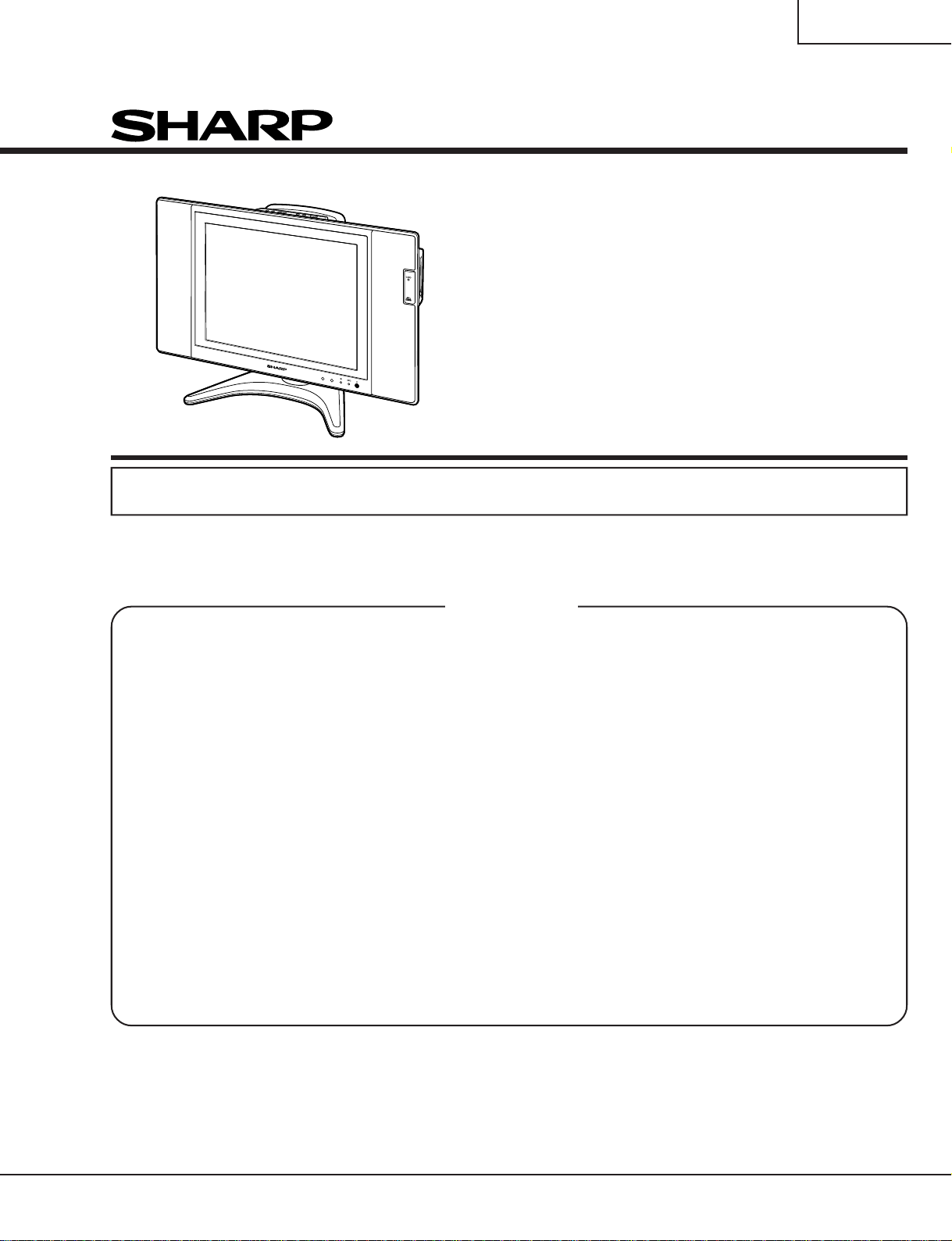
LC-15B5M
SERVICE MANUAL
S34Q7LC-15B5M
LCD COLOUR TELEVISION
MODEL
In the interests of user-safety (Required by safety regulations in some countries) the set should be restored to its original condition and only parts identical to those specified should be used.
CONTENTS
» IMPORTANT SERVICE SAFETY PRECAUTION.........................................................................................2
» SPECIFICATIONS ........................................................................................................................................4
» OPERA TION MANUAL .................................................................................................................................5
» DIMENSIONS ...............................................................................................................................................7
» REMOVING OF MAJOR PARTS ..................................................................................................................8
» ADJUSTING PROCEDURE OF EACH SECTION .....................................................................................13
» TROUBLE SHOOTING TABLE...................................................................................................................24
» CHASSIS LA YOUT .....................................................................................................................................28
» BLOCK DIAGRAM ......................................................................................................................................30
» OVERALL WIRING DIAGRAM ...................................................................................................................32
» DESCRIPTION OF SCHEMATIC DIAGRAM .............................................................................................34
» SCHEMA TIC DIAGRAM .............................................................................................................................35
» PRINTED WIRING BOARD ASSEMBLIES................................................................................................75
» REPLACEMENT PARTS LIST....................................................................................................................86
» P ACKING OF THE SET ............................................................................................................................101
LC-15B5M
Page
SHARP CORPORATION
Page 2
LC-15B5M
2
2
IMPORTANT SERVICE SAFETY PRECAUTION
Ë
Service work should be performed only by qualified service technicians who are
thoroughly familiar with all safety checks and the servicing guidelines which follow:
WARNING
1. For continued safety, no modification of any circuit
should be attempted.
2. Disconnect AC power before servicing.
CAUTION: FOR CONTINUED PROTECTION
AGAINST A RISK OF FIRE REPLACE ONLY WITH
SAME TYPE F3701 (2A, 250V), F3702 (1.25A, 250V),
F6501 (1.25A, 250V) AND F6502 (1.25A, 250V)
FUSE.
BEFORE RETURNING THE RECEIVER
(Fire & Shock Hazard)
Before returning the receiver to the user, perform
the following safety checks:
1. Inspect all lead dress to make certain that leads are
not pinched, and check that hardware is not lodged
between the chassis and other metal parts in the
receiver.
2. Inspect all protective devices such as non-metallic
control knobs, insulation materials, cabinet backs,
adjustment and compartment covers or shields,
isolation resistor-capacitor networks, mechanical
insulators, etc.
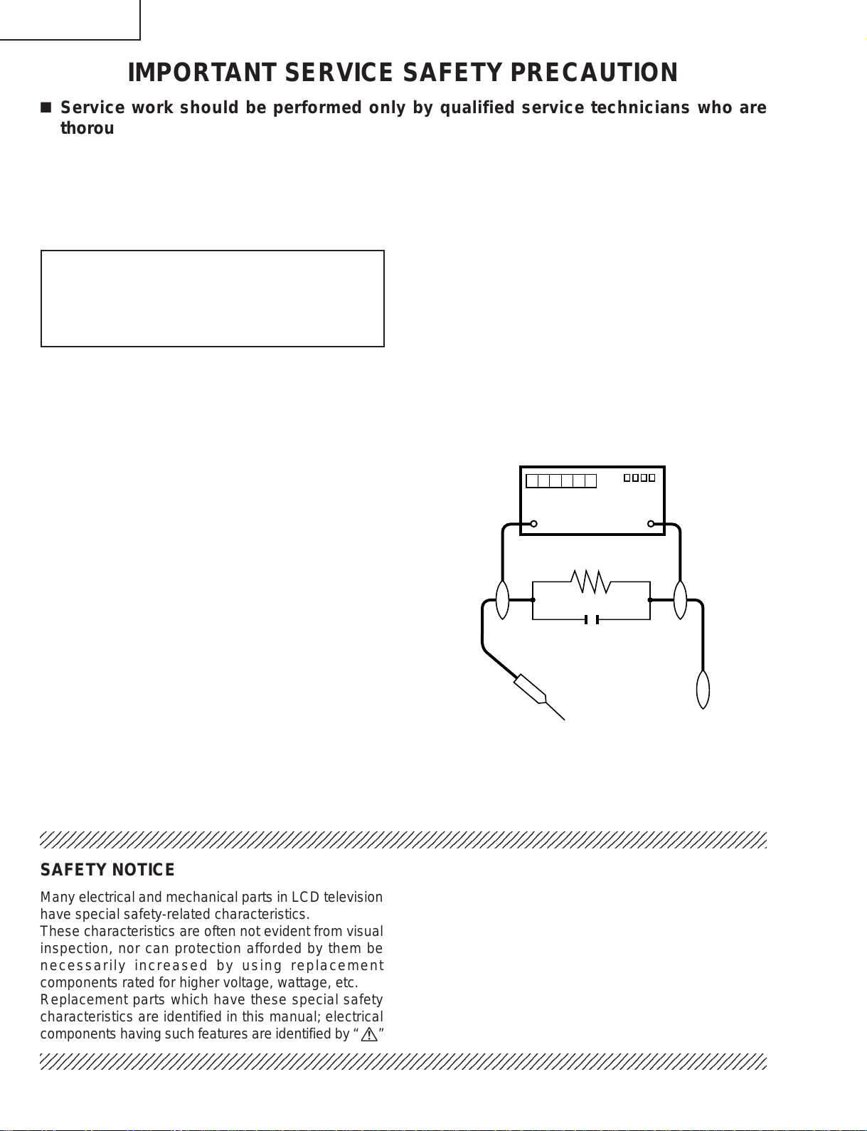
3. To be sure that no shock hazard exists, check for
leakage current in the following manner.
• Plug the AC cord directly into a 110~240 volt AC outlet,
and connect the DC power cable into the receiver's
DC jack. (Do not use an isolation transformer for this
test).
• Using two clip leads, connect a 50k ohm, 10 watt
resistor paralleled by a 0.15µF capacitor in series with
all exposed metal cabinet parts and a known earth
ground, such as electrical conduit or electrical ground
connected to an earth ground.
• Use an AC voltmeter having with 5000 ohm per volt, or
higher, sensitivity or measure the AC voltage drop
across the resistor.
• Connect the resistor connection to all exposed metal
parts having a return to the chassis (antenna, metal
cabinet, screw heads, knobs and control shafts,
escutcheon, etc.) and measure the AC voltage drop
across the resistor.
All checks must be repeated with the AC cord plug
connection reversed. (If necessary, a nonpolarized
adaptor plug must be used only for the purpose of
completing these checks.)
Any reading of 0.75V peak (this corresponds to 0.5
mA. peak AC.) or more is excessive and indicates a
potential shock hazard which must be corrected before
returning the monitor to the owner.
DVM
AC SCALE
50k ohm
10W
0.15 µF
TEST PROBE
TO EXPOSED
METAL PARTS
CONNECT TO
KNOWN EARTH
GROUND
234567890123456789012345678901212345678901234567890123456789012123456789012345678901234567890121
SAFETY NOTICE
Many electrical and mechanical parts in LCD television
have special safety-related characteristics.
These characteristics are often not evident from visual
inspection, nor can protection afforded by them be
necessarily increased by using replacement
components rated for higher voltage, wattage, etc.
Replacement parts which have these special safety
characteristics are identified in this manual; electrical
and shaded areas in the
Schematic Diagrams.
For continued protection, replacement parts must be
identical to those used in the original circuit.
The use of a substitute replacement parts which do not
have the same safety characteristics as the factory
recommended replacement parts shown in this service
manual, may create shock, fire or other hazards.
components having such features are identified by “ å”
234567890123456789012345678901212345678901234567890123456789012123456789012345678901234567890121
Replacement Parts Lists and
2
Page 3
LC-15B5M
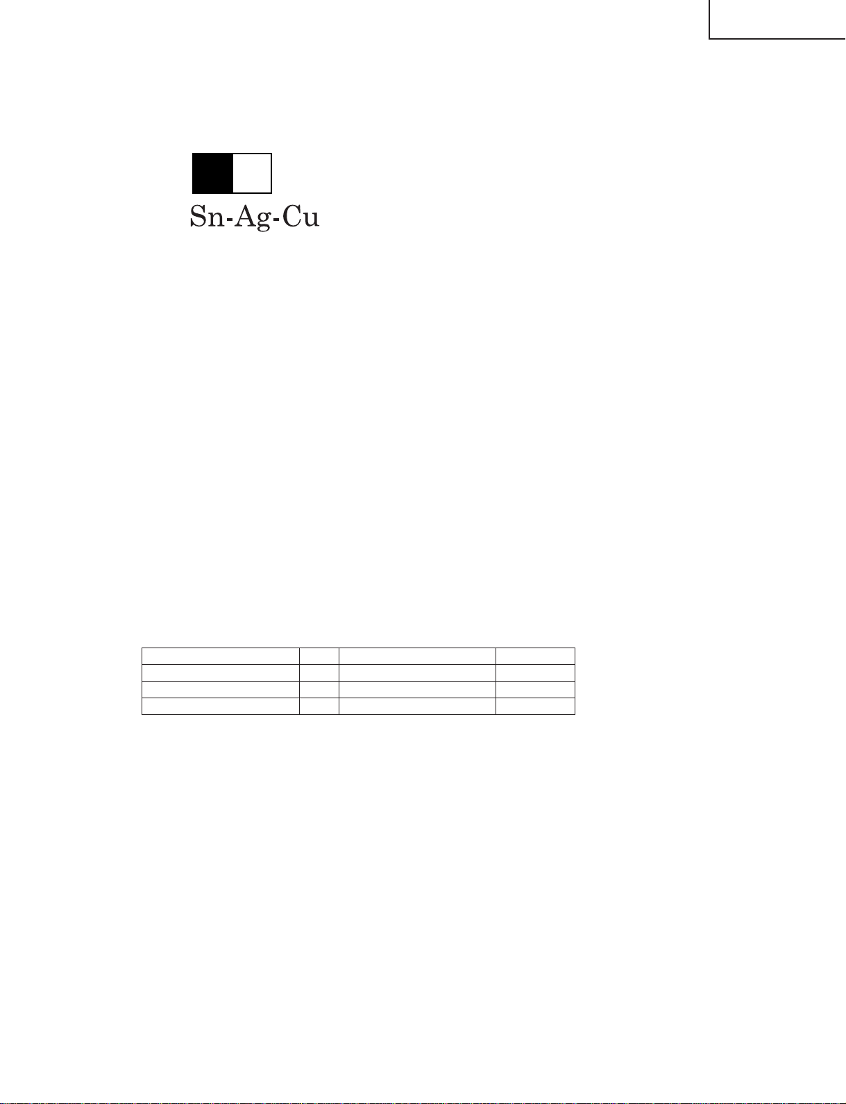
Precautions for using lead-free solder
1 Employing lead-free solder
"All PWBs" of this model employs lead-free solder. The LF symbol indicates lead-free solder, and is attached on
the PWBs and service manuals. The alphabetical character following LF shows the type of lead-free solder.
Example:
L Fa
Indicates lead-free solder of tin, silver and copper.
2 Using lead-free wire solder
When fixing the PWB soldered with the lead-free solder, apply lead-free wire solder. Repairing with conventional
lead wire solder may cause damage or accident due to cracks.
As the melting point of lead-free solder (Sn-Ag-Cu) is higher than the lead wire solder by 40°C, we recommend
you to use a dedicated soldering bit, if you are not familiar with how to obtain lead-free wire solder or soldering bit,
contact our service station or service branch in your area.
3 Soldering
As the melting point of lead-free solder (Sn-Ag-Cu) is about 220°C which is higher than the conventional lead
solder by 40°C, and as it has poor solder wettability, you may be apt to keep the soldering bit in contact with the
PWB for extended period of time. However, Since the land may be peeled off or the maximum heat-resistance
temperature of parts may be exceeded, remove the bit from the PWB as soon as you confirm the steady soldering
condition.
Lead-free solder contains more tin, and the end of the soldering bit may be easily corroded. Make sure to turn on
and off the power of the bit as required.
If a different type of solder stays on the tip of the soldering bit, it is alloyed with lead-free solder . Clean the bit after
every use of it.
When the tip of the soldering bit is blackened during use, file it with steel wool or fine sandpaper.
Be careful when replacing parts with polarity indication on the PWB silk.
Lead-free wire solder for servicing
Part No, ★ Description Code
ZHNDAi123250E J φ0.3mm 250g(1roll) BL
ZHNDAi126500E J φ0.6mm 500g(1roll) BK
ZHNDAi12801KE J φ1.0mm 1kg(1roll) BM
3
Page 4
LC-15B5M
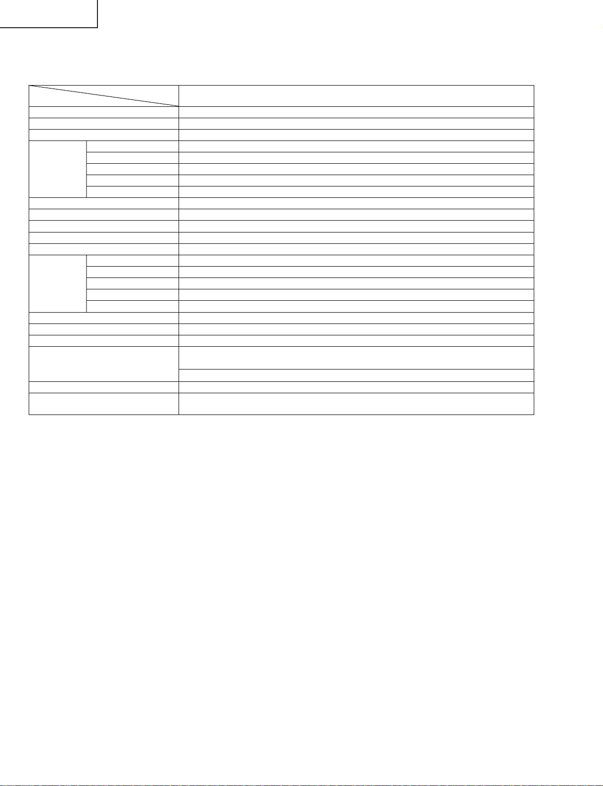
SPECIFICATIONS
ITEMS
LCD panel
Number of pixels 921,600 dots
Video colour systems World multi system
TV Standard (CCIR) I/DK/M/BG
TV Tuning System Auto preset tuning
TV function STEREO/BILINGUAL NICAM-BG, I, DK/A2 stereo-BG
AUTO PRESET Yes
CATV S1~S41 ch. Hyper Band
4-LINE DIGITAL COMB FILTER Yes
Brightness 430 cd/m
Viewing angles H: 170° V: 170°
Audio output 2.1 W × 2
Speakers 4 × 7 cm, 2 pcs.
AV1 Composite Video, S-Video, Audio
AV2 IN/OUT Composite Video, Audio IN/Composite Video, Audio OUT
Terminals
Image File Format JPEG files complying with DCF format
OSD LANGUAGE English/Chinese/Arabic
Power requirement DC 12 V, AC 110–240 V, 50/60 Hz
Power Consumption 43 W (0.7 W Standby):
Weight 5.7 kg w/o accessories
Accessories Remote control, Batteries (×2), Antenna cable, AC adapter,
ËAs a part of policy of continuous improvement, SHARP reserves the right to make design and specification changes for the LCD TV set
improvement without prior notice. The performance specification figures indicated are nominal values of production units. There may be
some deviations from these values in individual units.
COMPONENT Y, PB, PR/Audio
Headphone jack 3.5 mm ø jack (Front)
PC Card Slot PC Card Type II (PC Card Adapter)
MODEL
LC-15B5M
15” (38 cm) Advanced Super View & BLACK TFT LCD
2
AC 230 V (With AC adapter)
34 W : DC 12 V
AC cord, Cable holder, Operation manual
4
Page 5
OPERATION MANUAL
MAIN POWERMENUVOL
( )
/
( )
TV/VIDEOCH
( )
/
( )
LC-15B5M
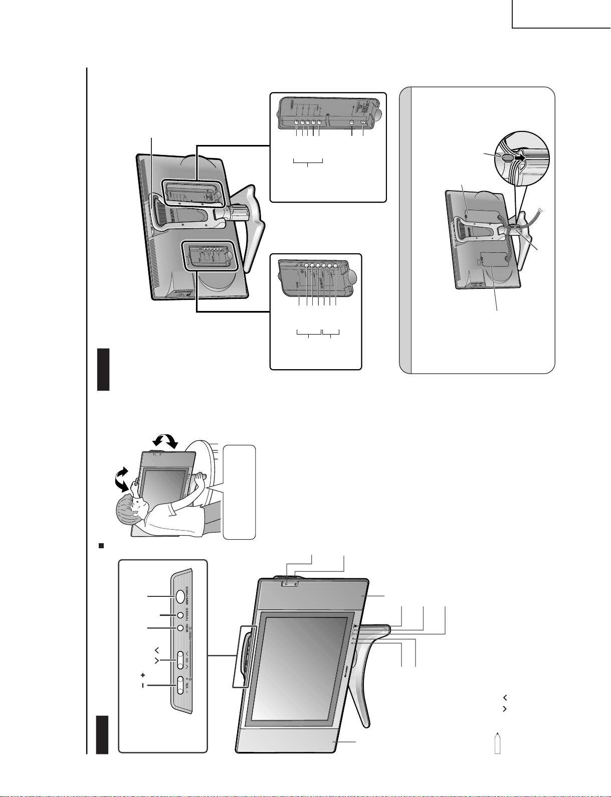
Upper control panel
Part Names of Main Unit
Controls
NOTE
• TV/VIDEO, CH (
)/(
), VOL (–)/(+) and MENU on the main unit have the same functions as the same buttons on the remote control.
Fundamentally, this operation manual provides a description based on operation using the remote control.
HEADPHONE jack
OPC sensor
Remote sensor
To change the vertical angle of the LCD TV
set, tilt the screen up to 5 degrees forward or
10 degrees backward. The LCD TV set can
also be rotated up to 25 degrees to right and
left. Please adjust the angle so that the LCD
TV set can be watched most comfortably.
Card Lamp
When timer recording is set: Orange
When recording: Red
Standby: Green
PC Card Slot
Speaker
Tilt the display by grabbing onto
the carrying handle while securely
holding down the stand with your
other hand.
How to adjust the angle
Speaker
Plug the headphone mini-plug into the Headphone jack
located on the front of the LCD TV set.
OPC indicator (Optical Picture Control)
The Optical Picture Control indicator lights up green when the
“Backlight” is set to “Auto (OPC)”.
POWER indicator
POWER indicator lights up green when the power is on, and
red when in the standby mode (the indicator will not light
when the main power is off). The indicator lights up orange
when the wake-up timer is set.
The examples used throughout this manual are based on
the LC-20B5M model.
*
Terminals
S-VIDEO
AV-IN1
VIDEO
AUDIO (R)
AUDIO (L)
VIDEO
AUDIO (R)
AUDIO (L)
AV-IN2/OUT
Y
ANT. (Antenna terminal)
POWER INPUT (DC12V)
AUDIO (L)
AUDIO (R)
P
B
P
R
COMPONENT
Carrying handle
Rear View
How to fix the cables
• Pull the cables connected to each terminal through the holes and close the left and right terminal covers.
Push the cables into the grooves of the support covers. Insert the cable holder (supplied) from above the
support cover and fix the cables.
Terminal cover
Cable holder
Terminal cover
Support cover
LC-15B5M
5
Page 6
LC-15B5M
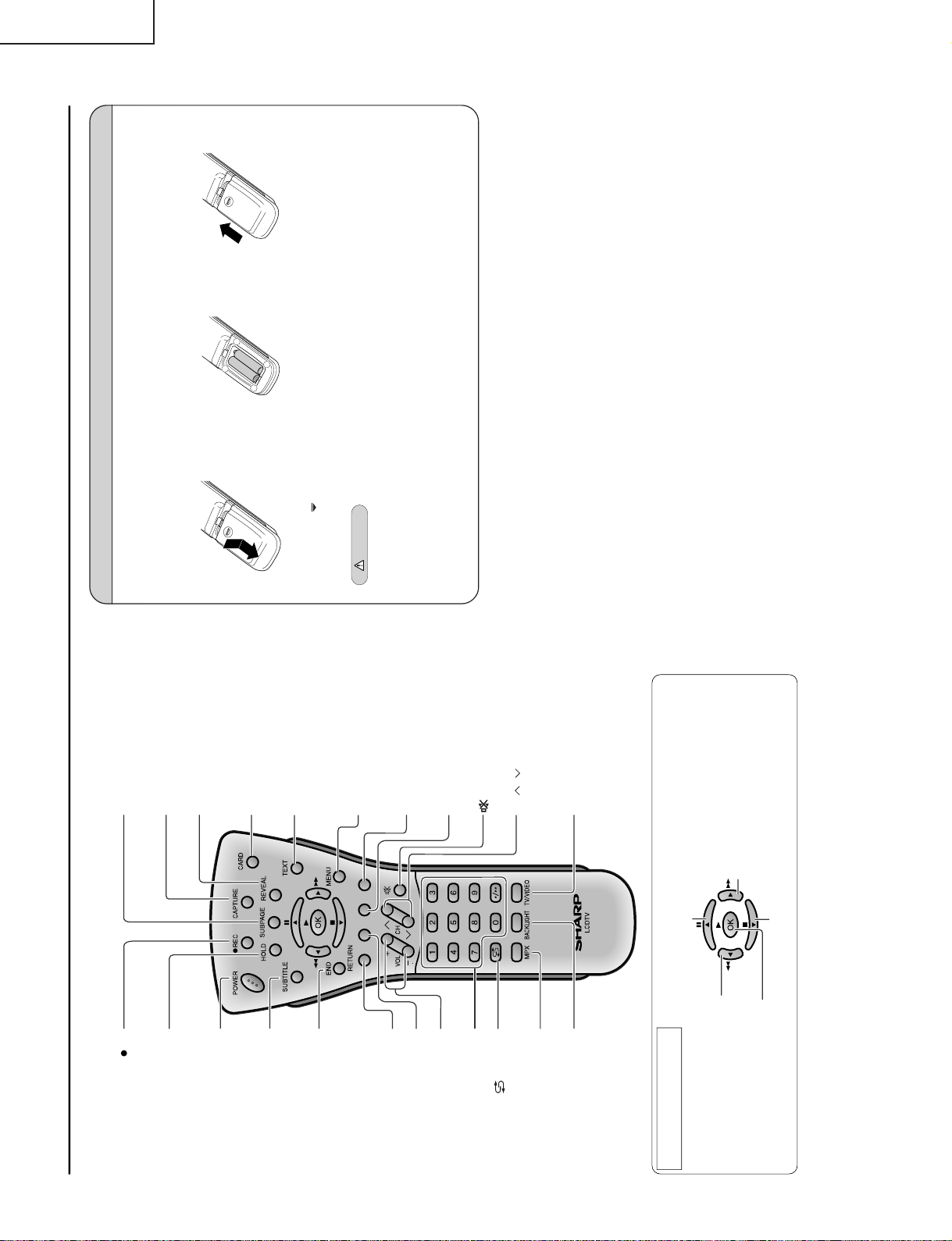
Part Names of Remote Control
Move the cursor to the upwards
(Select the menu items)
/
Still
(Pause the motion picture playback or card recording)
Move the cursor to the right
(Select the menu items)
/
Fast Forward
(Fast forwards the picture)
Move the cursor to the downwards
(Select the menu items)
/
Stop
(stop the motion picture playback or card recording)
OK
(Set the menu or items by selecting the cursor)
/
Play
(Playback the card)
Move the cursor to the left
(Select the menu items)
/
Fast Reverse
(Fast reverses the picture)
How to use the cursor during the
motion picture playback
SUBTITLE
Displays the Teletext
Subtitle directly.
HOLD
Temporarily holds the
current Teletext page.
REC
Records the motion
picture.
(Mute)
Switches the sound on and off.
Yellow,
Timer function Menu
Cyan, Status Display
Channel Select
MENU
Displays the TV menu or return
to normal screen.
VOL (+)/(
-
)
(Flashback)
Returns to the previous
channel.
Red, Picture Menu
END
Returns to normal screen
in Teletext mode.
RETURN
Return to the previous screen.
TEXT
Displays the Teletext mode
screen.
POWER
MPX
Switches the audio
mode.
REVEAL
Displays hidden information
such as solutions to riddles
and puzzles.
CARD
Switches the motion and
still picture.
SUBPAGE
Displays the Teletext
Subpage directly.
CAPTURE
Records the still picture.
TV/VIDEO
Switches the input source
between AV1, AV2, COMPONENT,
CARD and TV mode.
BACKLIGHT
Selects the brightness and
OPC of the display.
Green, Sound Menu
CH ( )/( )
Installing Batteries in the Remote Control
Before using the LCD TV set for the first time, install the two “AAA” size batteries supplied in the remote control. When the
batteries become depleted and the remote control fails to operate, replace the batteries with new “AAA” size batteries.
1
Open the battery cover.
2
Insert two “AAA” size batteries.
3
Close the battery cover.
Ë Place batteries with their
terminals corresponding to
the (+) and (–) indications in
the battery compartment.
Caution!
Precautions regarding batteries
Ë Improper use of batteries can result in a leakage of chemicals and/or explosion. Be sure to follow the instructions below.
• Place batteries with their terminals corresponding to the (+) and (–) indications.
• Different types of batteries have different characteristics. Do not mix batteries of different types.
• Do not mix old and new batteries. Mixing old and new batteries can shorten the life of new batteries and/or cause old
batteries to leak chemicals.
• Remove batteries as soon as they are depleted. Chemicals that leak from batteries can cause a rash. If chemical
leakage is found, wipe it off with a cloth.
• The batteries supplied with the LCD TV set may have a shorter operating time due to storage conditions.
• If the remote control is not to be used for an extended period of time, remove the batteries from the remote control.
Preparation
Ë Engaging the lower
claw with the remote
control, close the
cover.
Ë Slide the cover while
pressing the (
) part.
+
–
+
–
6
Page 7
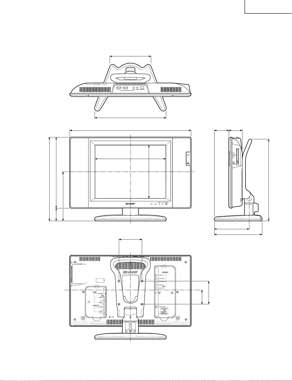
Unit: mm
310
178
307
231
213
363 (including rubber foot)
526
30756
5863
207
151
354 (including rubber foot)
62
100
100
LC-15B5M
DIMENSIONS
7
Page 8
LC-15B5M
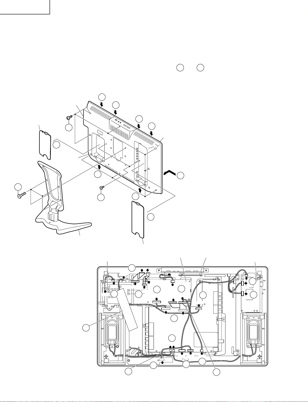
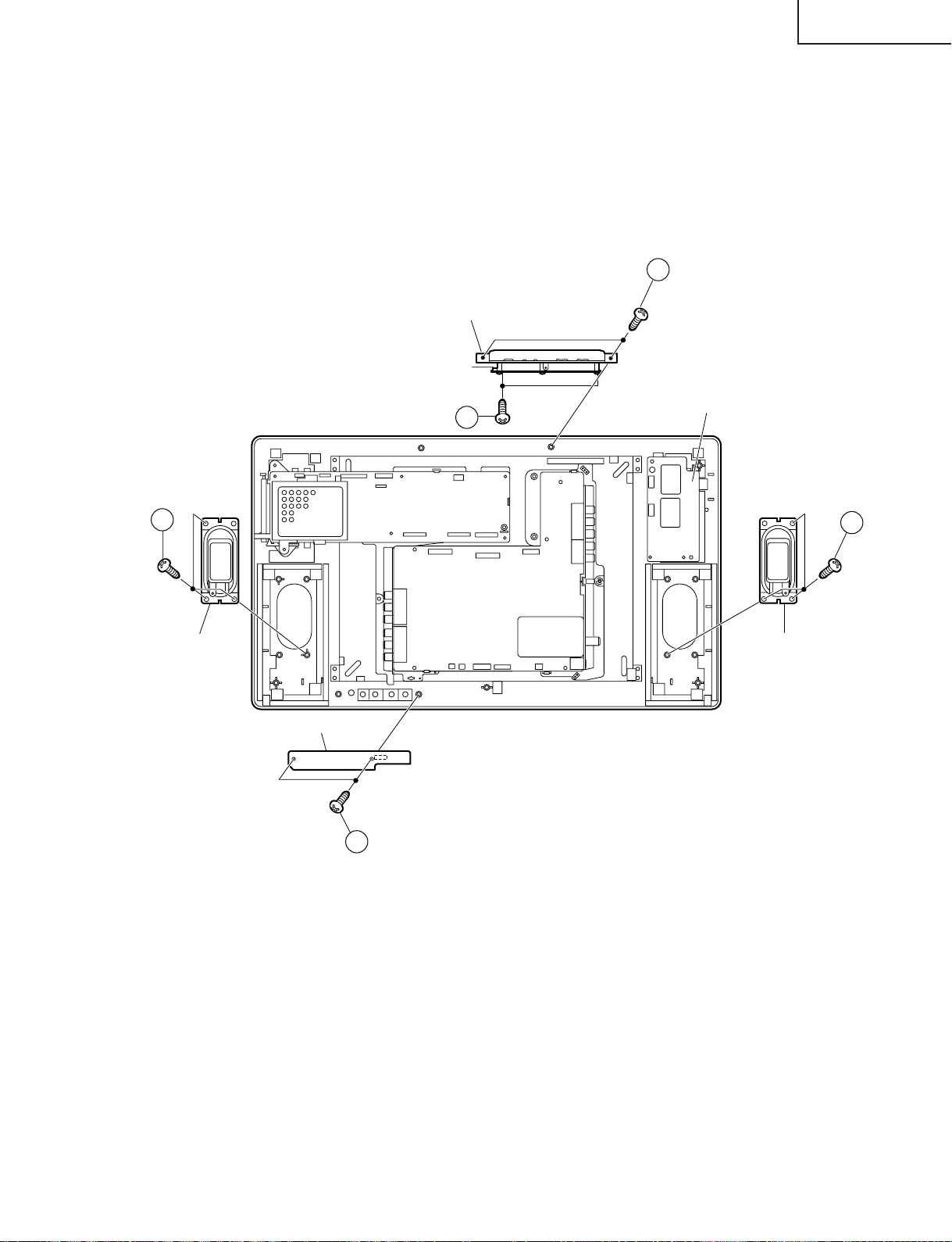
REMOVING OF MAJOR PARTS
1. Remove the four lock screws from the stand, and detach the stand.
2. Remove the terminal covers (large and small).
3. Remove the two terminal screws.
4. Remove the eight lock screws from the cabinet B.
5. With the card eject button held down, open the cabinet in order of
sliding it toward the PC card slot.
6. Remove the wire holder and tape, and disconnect the connecting cable.
7. Disconnect all the connectors from all the PWBs.
5-4
PC Card slot
5-3
5-1
thru
, and detach the cabinet B by
5-6
Terminal Cover (S)
1
2
Cabinet B
5-2
4
5-6
3
5-5
5-1
Cabinet A
5
2
Stand
Terminal Cover (L)
Card LED PWB
Main PWB
Operation PWB
Inverter PWB
6
Tape
P9201
P2005
7
Wire holder
P5003
6
7
SC1204
P4050
SC1202
P2003
SC2001
7
7
P701
SC3403
7
P3201
7
P2006
P1601
7
SC1201
P6500
P6501
P6502
7
7
Analog PWB
7
P3701
P3302
P3702
P3404
P4001
7
R/C, LED PWB
P3704
7
7
6
Wire holder
8
Page 9
LC-15B5M
8. Remove the two lock screws from the operation panel (top cover), and detach the operation panel (top cover).
9. Remove the two lock screws from the operation PWB, and detach the operation PWB.
10. Remove the two lock screws from the R/C, LED PWB, and detach the R/C, LED PWB.
11. Remove the three lock screws each from the speakers (left and right), and detach both the speakers.
8
Operation Panel (Top Cover)
Operation
PWB
9
Inverter PWB
11
Speaker (R)
Main PWB
11
Analog PWB
Speaker (L)
R/C, LED PWB
10
9
Page 10
LC-15B5M
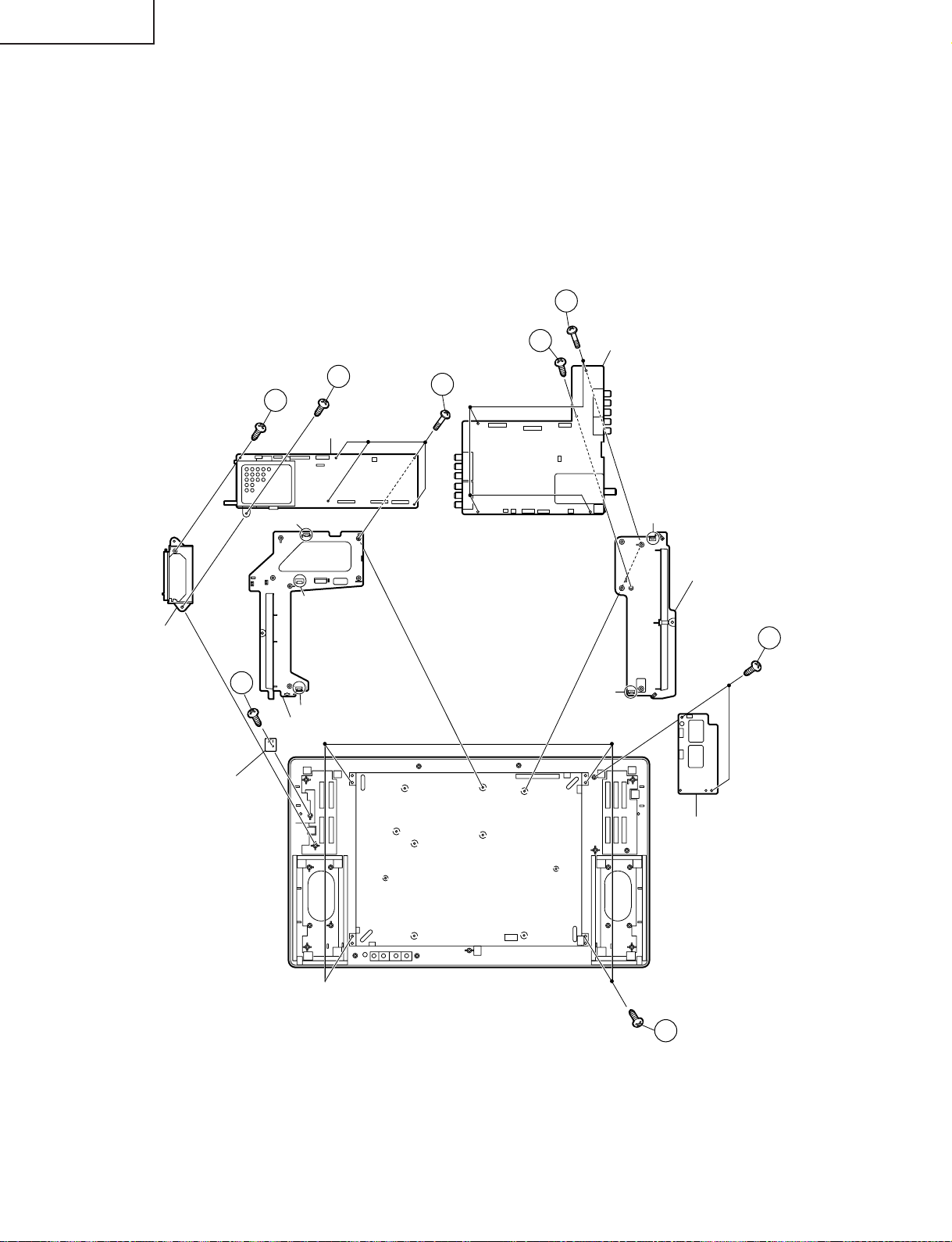
12. Remove the two lock screws from the inverter PWB, and detach the inverter PWB.
13. Remove the one lock screw from the card frame cover over, and detach the card frame cover.
14. Remove the five lock screws from the main PWB, and undo the claw a. Detach the main PWB by lifting the area
around the claws and pulling the PWB out.
15. Remove the five lock screws from the analog PWB, and undo the claws b and c. Detach the chassis frame (right)
from the analog PWB by pulling out the terminals. In the same way, undo the claws d and e, and detach the
chassis frame (left) from the analog PWB by pulling out the terminals.
Note: When detaching the main PWB and analog PWB, be careful not to break the PWB-fixing claws.
16. Remove the one lock screw from the card LED PWB, and detach the card LED PWB.
17. Remove the four lock screws from the LCD panel unit, and detach the LCD panel unit.
15
Card Frame Cover
16
Card LED PWB
13
14
Main PWB
a
b
c
Chassis Frame (R)
14
15
Analog PWB
d
Chassis Frame (L)
12
e
10
Inverter PWB
17
Page 11
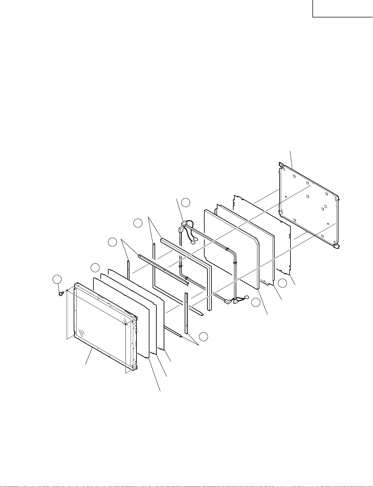
» Precautions in handling the LCD panels
Reflection Sheet (Cover)
(PSHEP0307CEZZ)
Lamp unit
(KLMP-A030WJZZ)
Back Shield
(PSLDMA313WJN1)
Reflection Sheet-2
(PSHEP0285CEZZ)
Reflection Sheet-1
(PSHEP0284CEZZ)
Light Guide Plate
(PGiDMA011WJZZ)
Reflection/deflection Sheet
(PSHEP0281CEZZ)
Diffusion Sheet
(PSHEP0283CEZZ)
Prism Sheet
(PSHEPA141WJZZ)
15" LCD Panel Unit
21
22
18
19
23
24
20
20
Reflection Mirror
Reflection Mirror
1. Work in a clean room (with humidities below 50%).
2. Be sure to wear an anti-static armband.
3. Handle the panels on an electro-conductive mat.
4. Be careful not to fall, shake and shock the panels.
18. Remove the four lock screws from the LCD panel unit.
19. Detach the diffusion sheet, prism sheet and reflection/deflection sheet.
20. Detach the four reflection mirrors.
21. Detach the two reflection sheets (Cover).
22. Remove the lamp unit.
23. Detach the Light guide plate.
24. Detach the two reflection sheets-1, -2.
LC-15B5M
11
Page 12
LC-15B5M
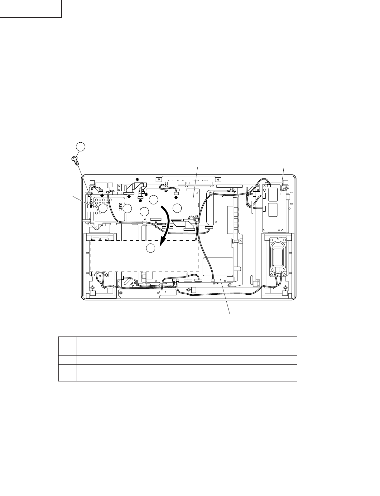
» Precautions in servicing Side B (back) of the main PWB unit
1. Disconnect the FFC (flat cable) from between the main PWB (SC1204) and LCD panel. Connect the servicespecific extension FFC (flat cable) (QCNW-A556WJZZ) instead.
2. Disconnect the FFC (flat cable) from between the main PWB (SC1201) and LCD panel. Connect the servicespecific extension FFC (flat cable) (QCNW-A555WJZZ) instead.
3. Disconnect the FFC (flat cable) from between the main PWB (SC1202) and LCD panel. Connect the servicespecific extension FFC (flat cable) (QCNW-A553WJZZ) instead.
4. Disconnect the lead (between main PWB (P2003) and operation PWB) from the P2003 connector. Connect the
service-specific extension cable (QCNW-B748WJQZ) instead.
5. Disconnect the lead (between card LED PWB (P9201) and main PWB (P2005)) from the P2005 connector.
6. Remove the four lock screws from the main PWB. Detach this PWB from the chassis frame and turn it over.
7. Remove the lock screw from the card LED PWB and detach the card LED PWB from the cabinet A. Reconnect
the lead (disconnected in Step 5 above) to the main PWB (P2005).
7
Main PWB
P4050
3
P2003
4
6
Card LED PWB
P9201
P2005
SC1202
SC1204
5
SC1201
1
2
6
Main PWB
(Side-B)
Step Part No. Description
1 QCNW-A556WJZZ Extension Cable 50-pin Main (SC1204)-LCD panel
2 QCNW-A555WJZZ Extension Cable 20-pin Main (SC1201)-LCD panel
3 QCNW-A553WJZZ Extension Cable 30-pin Main (SC1202)-LCD panel
4 QCNW-B748WJQZ Extension Cable 5-pin Main (P2003)-Operation (P4050)
Inverter PWB
Analog PWB
12
Page 13

LC-15B5M
ADJUSTING PROCEDURE OF EACH SECTION
The best adjustment is made before shipping. If any position deviation is found or after part replace is performed, adjust
as follows.
Preparation for Adjustments
Use the exclusive-use AC adapter or stable DC power supply.
AC adapter: UADP-A043WJPZ
DC power supply: 12 ± 0.5V 5.0A
1. Adjustment Procedure
1-1. Adjusting the checker
Turning on the power (initialization) → Setting the model and size in inches → Transferring the model-specified
data to the E2PROM (I2C) → Calling the adjustment process mode
1-2. Adjusting the finish process
Reassembling the set → Turning on the power → Calling the adjustment process mode (using the remote
controller) → Adjusting the counter bias, TV contrast and white balance
2. Calling the MAIN adjustment process mode
There are the following two ways to choose from.
• Set the Pin (81) (KEY4) or Pin (82) (KEY5) of IC2001 (microprocessor) to "L", turn on the power.
• For servicing, hold down the "TV/VIDEO" and "MENU" keys at once, and turn on the "POWER" switch. (Make
sure the process mode "K" appears at the top left of the screen.) Then press the "CH (Ù)" and "VOL (–)" keys
at once. (Make sure the adjustment process mode screen shows up.) To quit this mode, turn off the power. (Or
turn off the "POWER" switch or use the remote controller’s "OFF" key.)
3. Using the keys for the adjustment process
Selecting a reception channel
• Using the "CH (ù)/(Ù)" key, turn up and down reception (broadcasting) channels.
Just click on the key, and channels are selected on by one.
Hold down the key, and the next receivable channel is searched up and down.
• Adjustment items
Adjust each of the items by using the "MENU", "CURSOR UP/DOWN" and "VOL (+)/(–)" keys (on the set or on
the remote controller).
• Select an adjustment item using the "CURSOR UP/DOWN" key.
• An adjustment item is toggled on and off by activating the MENU SELECT key (next item).
Let’s suppose that the item at the bottom of a page is now selected. When the "MENU" key is activated here, the
item at the top of the next page will be selected.
4. Initialization
4-1. Set pins (81) and (82) of IC2001 (microprocessor) to GND. Turn on the power.
4-2. Select the model number "A642M".
~Once "A642M" has been selected, the screen shuts off and the power turns off. But the power turns
itself on to get the set restarted. (The microprocessor resets itself due to a change in model number.)
4-3. Writing model by model data.
For the Australia version (LC-15B5M(X)), get it initialized first and then make the settings, listed below, on it.
Adjustment process page Item OSD setting
2 N358 TV COLOR 40 → 36
2 N358 AV COLOR 6F → 65
4 PAL TV COLOR 6F → 65
4 PAL AV COLOR 6F → 65
6 SECAM TV COLOR 50 → 46
6 SECAM AV COLOR 50 → 46
8 PAL60 TV COLOR 6F → 65
8 PAL60 AV COLOR 6F → 65
2F0 N443 TV COLOR 50 → 46
2F1 N443 AV COLOR 50 → 46
32B CARD COLOR 43 → 39
338 D2 COLOR 6F → 65
13
Page 14
LC-15B5M
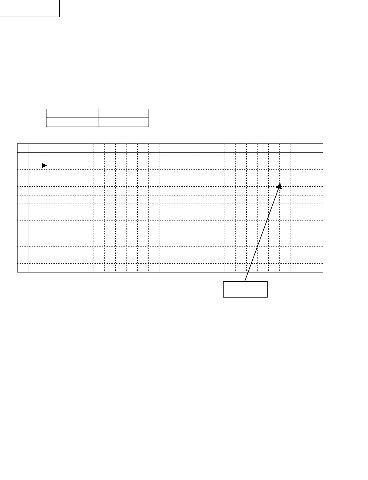
5. Adjustment
5-1. Counter bias adjustment: COM BIAS on page 2
Adjust the "COM BIAS" setting until the contrast gets optimum (the black portion blackest). The adjustment
guideline is around 100.
5-2. TAMP adjustment
1) Feed the colour bar pattern signal.
2) See if the "Y" reading on adjustment process page 2 is within the range shown below. If not, adjust the
"NTSC TAMP" setting to bring the "Y" reading within the specified range.
3) If the "NTSC TAMP" setting has been readjusted, write down its new setting in the "PAL TAMP" and
"SECAM TAMP" items manually.
Model LC-15B5M/M(X)
Adjustment value 174~189
(Page 2 of adjustment process OSD)
0 1 2 3 4 5 6 7 8 9 10 11 12 13 14 15 16 17 18 19 20 21 22 23 24 25 26
0
1
2
3
4
5
6
7
8
9
10
11
12
13
2
COM B I AS
TAMP L 71
YD TA
TAMP
NTSC TAMP
PAL TAMP 27
SECAM
RCUTOF
GCUT OF
BCU TOF
R – GA IN
G – GA IN
B – GAIN
A
H
TAMP
F
F
F
1
0
0
0. 4
00
4
815
819
27
2
7
3– 7
2– 5
0– 3
9.4
9.6
9
Y Data
(White 75%)
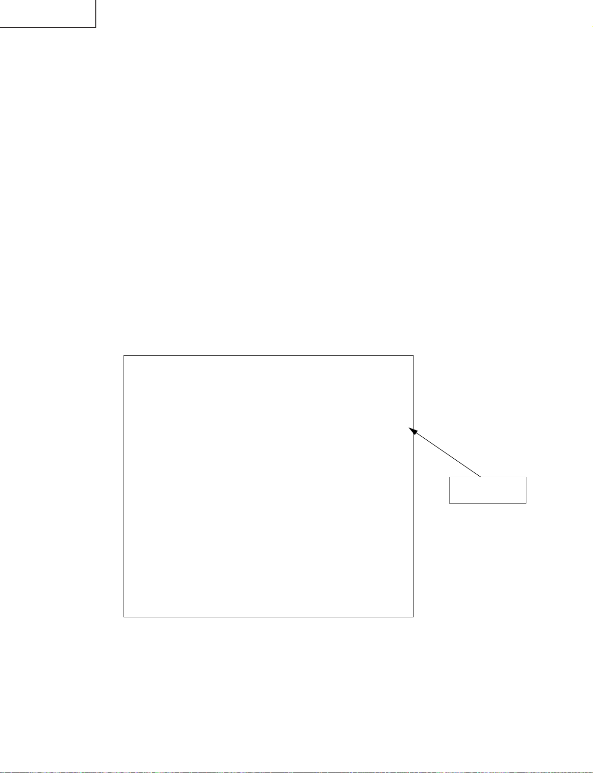
5-3. White balance adjustment
1) Feed the monoscope pattern signal.
2) Adjust the "RCUTOFF", "BCUTOFF", "R-GAIN" and "B-GAIN" settings on adjustment process page 3 to
achieve the colour at the same level as with the standard set.
5-4. AD converter level adjustment (D2 input)
1) Receive the colour bar signal (480P) that makes the top left 75% white.
2) Select "AUTO GAIN-OFFSET" on adjustment process page 3. Press the "VOL UP/DOWN" or "CURSOR
RIGHT/LEFT" button for automatic adjustment.
14
Page 15

LC-15B5M
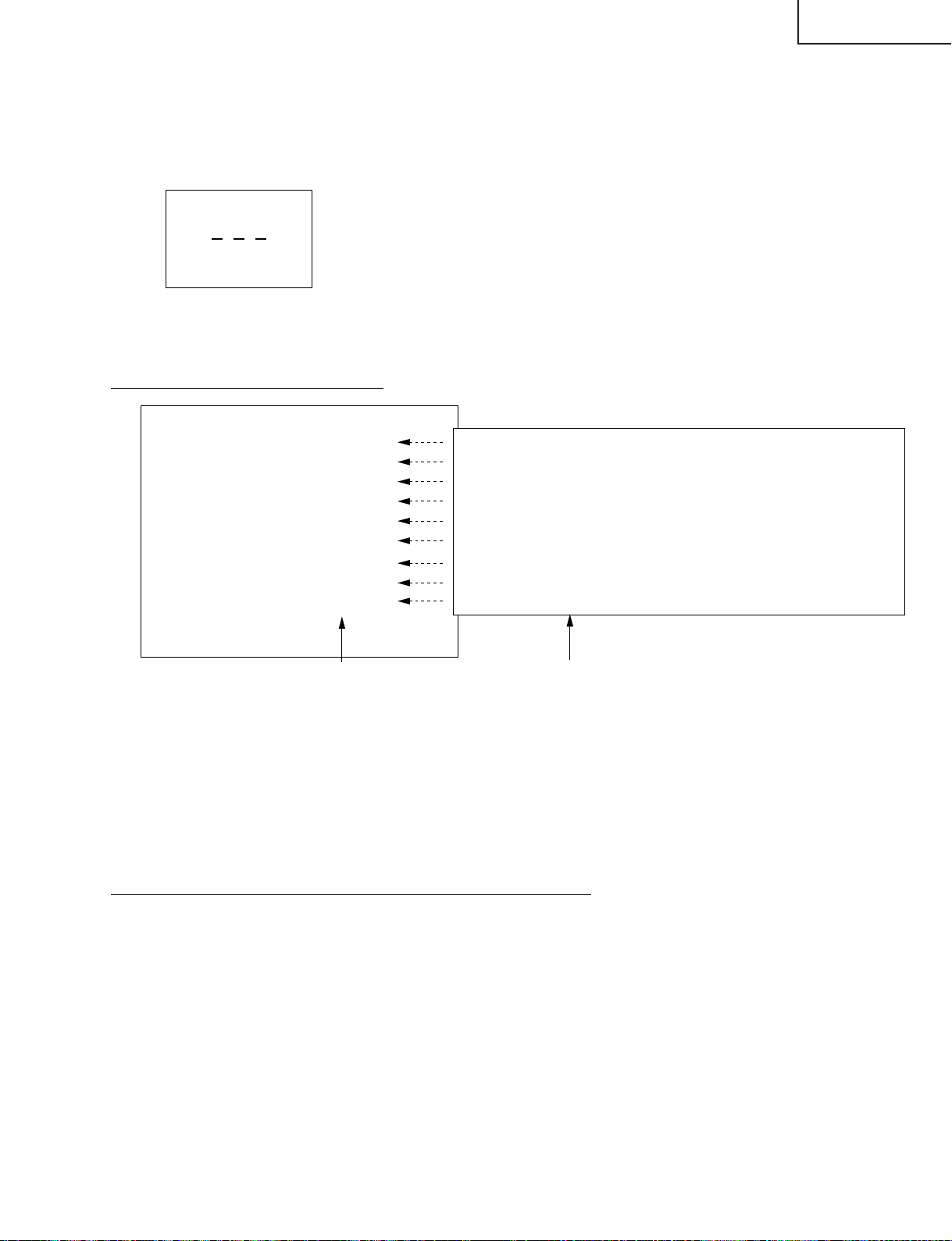
5-5. Other adjustments (SOUND, VPC, S2310, DAC, TUNER, OTHERS, TEXT, G/A)
1) Move the cursor to a desired item on page 4 of adjustment process menu. Press the CURSOR LEFT/
RIGHT keys, "VOL (+)/(–)" keys or OK key to select the item.
4
I2C DATA 000000000000
I2C DATA WAIT
SOUND
VPC
S2310
DAC
TUNER
OTHERS
TEXT
G/A
2) The adjustment process menu of the item appears on the screen. The settings are now ready to change.
Screen with SOUND selected
SOUND1
VOLUME 0
MSP DATA 000000000000
MSP DATA WAIT
AVC OFF
CARRIER MUTE ON
SP TEST OFF
SHUTTER WAIT 100
IGR THR 12D
MSP ASS WAIT 300ms
3) To go back to page 4 of adjustment process menu, press the FLASHBACK key on the remote controller.
15
Page 16
LC-15B5M
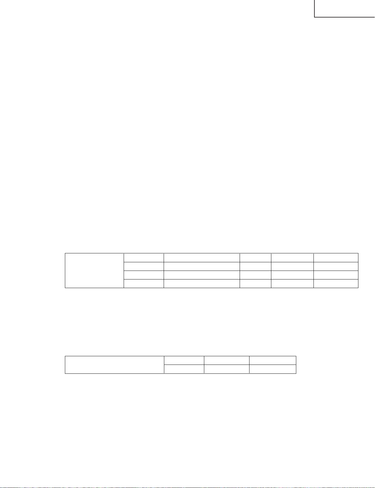
6. Lamp error detection
6-1. Functional description
This LCD colour television has a function (lamp error detection) to be turned off automatically for safety
when the lamp or lamp circuit is abnormal.
If the lamp or lamp circuit is abnormal, or some other errors happen, and the lamp error detection is
executed, the followings occur.
1 The main unit of television is turned off 5 seconds after it is turned on. (The power LED on the front side of
TV turns from green to red.)
2 If the situation 1 happens 5 times sequentially, television can not be turned on. (The power LED remains
red.)
6-2. Countermeasures
6-2-1. Check when turning off the lamp error detection
When television is turned off by the lamp error detection mentioned above, it enters the adjustment
process with the power LED red. Entering the adjustment process turns off the error detection and turns
on TV .
This enables the operation check to detect errors in the lamp or lamp circuit.
Check whether "ERROR NO RESET" on line 4, page 1 of the adjustment process is 1 or more. If it is 1
or more, it indicates the lamp error detection was executed.
6-2-2. Resetting of the lamp error count
After confirming that the lamp or lamp circuit is normal, reset the lamp error count. Select "ERROR NO
RESET" on line 4, page 1 of the adjustment process and set the number to 0 using the volume button.
Page 1 of the adjustment process
1
M O D E L A642M
I N C H S I Z E 15
E R R O R N O R E S E T 5
P U B L I C M O D E OFF
E X T C O N T R O L OFF
E X T M O D E UART
U P D A T E M O D E NORMAL
T E X T R E S E T OFF
V E R R O M 1. 0 0A G AI B U 0. 0 0 0
Reset 0
Afterwards, perform the operation check to confirm that the lamp error detection does not function.
16
Page 17
7. Public mode
• How to enter into PUBLIC MODE
1. Turn off TV by pressing MAIN POWER switch.
2. While pressing "MENU" key and "VOL(+)" key at the same time, press MAIN POWER switch for more than 2
seconds.
TV will turn on, and you will see the screen display a setting pass word of PUBLIC MODE. (See Figure 1)
Figure 1
3. Press "0", "2", "7" key of Remote control, you will see the screen display a setting of PUBLIC MODE.
(See Figure 2)
• Setting screen of “PUBLIC MODE”
PUBLIC MODE
MAXIMUM VOLUME [ 60]
VOLUME FIXED [VARIABLE]
REMOTE CONTROL [RESPOND]
USER CONTROL [RESPOND]
MENU BUTTON [RESPOND]
ON SCREEN DISPLAY [YES ]
START MODE [NORMAL ]
INPUT MODE FIXED [NORMAL ]
SOUND ONLY MODE [NO ]
RESET
ENTER
1 ↔ 2 ··· ↔ 59 ↔ 60
VARIABLE ↔ FIXED
RESPOND ↔ LIMITED ↔ NO RESPOND
RESPOND ↔ NO RESPOND
RESPOND ↔ NO RESPOND
YES ↔ NO
NORMAL ↔ AV1 ↔ COMPONENT↔ CARD ↔ CH1 ↔ CH2
VARIABLE ↔ FIXED
NO ↔ YES
↔ CH99 ↔ CH0
LC-15B5M
...
↔ CH98
Figure 2
Factory setting
Adjust setting
1. You can select each item of functions by pressing cursor UP/DOWN keys or CH(ù)/(Ù) Keys on the remote
control or CH(ù)/(Ù) keys on the LCD TV. The letter of selected item turns to yellow colour when you selected
it.
2. The setting position of each item of functions is made by pressing cursor RIGHT/LEFT keys on the remote
control or VOL (+)/(–)keys on the LCD TV.
3. Select ENTER position after you set all functions, and press cursor RIGHT/LEFT keys on the remote control
or VOL(+)/(–)keys on the LCD TV for confirmation.
Unless otherwise, the settings will not be memorized.
• 6-functions Public Mode settings expand for public application
1. MAXIMUM VOLUME (1—————60)
You can set the maximum volume at your desire level.
2. VOLUME FIXED (VARIABLE/FIXED)
You can fix the sound volume at your desire level.
When you set to "FIXED", the sound volume which you just set is fixed.
3. REMOTE CONTROL (RESPOND/LIMITED)
If you set "LIMITED", remote control keys of POWER, CH(ù)/(Ù), VOL(–)/(+) and BACKLIGHT keys are
responded, but other keys are not responded.
This is a position that you can not make MENU adjustments.
4. USER CONTROL (RESPOND/NO RESPOND)
"NO RESPOND" means that the TV does not respond when you press a user control buttons except main
power button on the main unit.
17
Page 18

LC-15B5M
5. MENU BUTTON (RESPOND/NO RESPOND)
With "NO RESPOND" selected, the remote controller and the set's MENU key are disabled.
6. ON SCREEN DISPLAY (YES/NO)
If you set "NO" position, OSD will not appear.
7. START MODE (NORMAL↔AV1↔COMPONENT↔CARD↔CH1↔CH2
When any other item than "NORMAL" has been selected, the set gets started in the selected input mode or
channel at the next switch-on.
8. INPUT MODE FIXED (VARIABLE↔FIXED)
(* This item cannot be selected if the start mode is "NORMAL".)
If "FIXED" has been selected, any channels and input modes other than those selected in the start mode cannot
be picked up.
9. SOUND ONLY MODE (NO↔YES)
(* This item cannot be selected if "NO" appears on the on-screen display.)
Let's suppose that this item has been selected and the BACKLIGHT key on the remote control has been
pressed. The item "Backlight [Off]" can now be selected next to the item "Backlight [Dark]".
Screen with "Backlight [Off]" selected
...
↔CH98↔CH99↔CH0)
Count-down started from 5
Backlight [Off] Turns off in 5 secs.
Five seconds later, the screen shuts off and the sound alone is heard.
Once in this mode, no picture but the OSD appears. But the channels and sound volume can still be changed.
To quit this mode, press the BACKLIGHT key on the remote control again and select any item other than
"Backlight [Off]".
10. RESET
You can cancel all Public Mode settings. (It returns to the factory setting.)
11. ENTER
You make sure after you have specified all functions, then press the enter key. Unless otherwise you press
the enter key, all positions that you have selected will not be set.
<CAUTION>
After setting "FIXED" mode (VOLUME FIXED or INPUT MODE FIXED), perform the following operation.
1 Press MENU to display the MENU screen.
2 Press \/| to select "Features".
3 Press '/" to select "Timer function" and
press OK.
4 Press '/" to select "Wake-up timer" and
press OK.
5 Press OK to set the clock.
6 Press '/" to select "Wake-up timer".
7 Press \/| to set "00:01".
8 Press '/" to select "Set".
9 Press \/| to select "ON" and press OK.
10 Press OK.
11 Press '/" to select "Wake-up timer".
12 Press \/| to set "00:00".
13 Press '/" to select "Set".
14 Press \/| to select "OFF" and press OK.
15 Press MENU to exit.
18
Page 19
8. Functions of the PC card
8-1. Product outline
SHARP has adopted its original "ASV *2 method low-reflection black TFT flat panel" that can reproduce the
high-contrast images with firm black even in bright rooms. "QS technology" *1 reduces residual images even
for quick-moving subjects to realize eye-friendly images, and "I/P conversion for 3-D motions" suppresses
roughness and flickering. They help you watch the high-contrast and clear images from any angles.
Furthermore, this product is equipped with "PC card slot" to record TV programs on memory cards, and to
show the still images taken with digital cameras on the large screen of an LCD TV with memory cards*.
This model has new design that has side-speakers designed by Toshiyuki Kita, a world-known industrial
designer. The speakers are punching metal-processed, so they have a style showing quality sound capabilities.
The screen properties are, needless to say , much superior to CRT TV sets: low power consumption, long life
backlight, and other power-saving features, as well as reduced flickering.
* QS --> only for LC-20B5M (not available on LC-15B5M)
<CARD FUNCTIONS>
(1) Enjoying recorded TV programs
To record the program you are watching, all you need is just push the record button. Supporting the hard
disc PC cards newly realizes long-time recording. There are lots of recording functions*, including "T race
Recording" (Going back to record to a few seconds before starting recording), "Reserved Recording" (Up
to 8 programs programmable a month) and "Easy Recording" (Finish time presettable during recording),
and you can enjoy the recorded programs on full screen.
* The video record system is MPEG-4. Smooth video with 25 frames/sec is realized.
(SD memory cards, Multimedia cards, Compact flashes, Smart media, Memory sticks, xD picture cards
and Micro drive are supported. For use, the PC card adapter specific for each memory card is necessary.
Names of memory cards are trademark.)
• Video Recording/Playing functions
One scene in the TV program you are watching can be recorded on memory cards. The recorded video
can be readily reproduced on demand. The T race Recording function records from a few seconds before,
so you need not worry about delaying the use of the remote controller. Three recording modes (SP/LP/
EP) are available for your applications.
LC-15B5M
Record mode Application Frame rate 256 MB card 5 GB card
Record time guideline
FINE 25
NORMAL
PORTABLE
Standard quality mode
Long time record mode
Portable device compatible mode
25
12.5
Approx. 10 min.
Approx. 30 min.
Approx. 1 hr.
Approx. 4 hrs.
Approx. 10 hrs.
Approx. 25 hrs.
* Record time is variable for the TV reception condition and the video contents.
* Ground-based broadcasting and external input (except for SCART RGB) that are not copy-protected can
be recorded.
* If the file capacity is over 4 GB, or the record time is longer than 12 hours, recording/playing is impossible.
• Still-Picture Recording/Playing functions
1) One scene in a TV program can be recorded on memory cards as a still image.
• You can readily record text information that you have made a memo until now.
Number of still images to be recorded
Recording size 32 MB card 128 MB card
Approx. 300
Approx. 1000
* The number of images is variable for the TV reception condition and the image contents.
2) Enjoying still images taken with digital cameras
With memory cards and on the large screen of an LCD TV, you can readily show still images captured
with digital cameras*.
* Only JPEG still images that were recorded to fit the standard (Design rule for Camera File system: DCF)
by Japan Electronics and Information Technology Industries Association Corp are playable.
* The number of files displayable is up to 1,024, including video and still images.
19
Page 20
LC-15B5M
8-2. PC Card Unit Spec
(1) Still-Picture Mode
1) Recording/Play File Format Based on JPEG/DCF
2) Recording Pixel Numbers 640x480
3) Playing Pixel Numbers 640x480
(2) Motion-picture Mode
1) File system ASF
(3) Motion picture Format
SP (Fine mode) MPEG4 QVGA (320x240) 2.5Mbps 25fps
LP (Normal Mode) MPEG4 QVGA (320x240) 1.0Mbps 25fps
EP (Portable Mode) MPEG4 QVGA (320x240) 384Kbps 12.5fps
Fitting Time Mode MPEG4 QVGA (320x240) Variable 25fps
(4) Audio Format
SP (Fine mode) WMA 2ch (Stereo) 32KHz 48Kbps
LP (Normal Mode) WMA 2ch (Stereo) 32KHz 48Kbps
EP (Portable Mode) G.726 1ch (monoral) 8KHz 32Kbps
Fitting Time Mode WMA 2ch (Stereo) 32KHz 48Kbps
Video Codec Picel Numbers Transfer Rate Frame Rate
Video Codec No. of Channel Sampling frequency Frame Rate
(5) Maximum file size
1) 1024 file (Still & Motion)
2) 4 GB
3) 12 hour
(6) Applicable Card media
HDD Card
Micro Drive
Compact Flash Card
Memory Stick/-DUO/-PRO
SD Card/mini SD
Multi media Card
xD Card
Smart Media
(7) PC Card Slot Interface 68pin PCMCIA
...
Max 5 GB
...
Max 2 GB
...
Max 2 GB
...
Max 128MB/1GB
...
Max 512/32MB
...
Max 128MB
...
Max 128MB
...
Max 128MB
20
Page 21
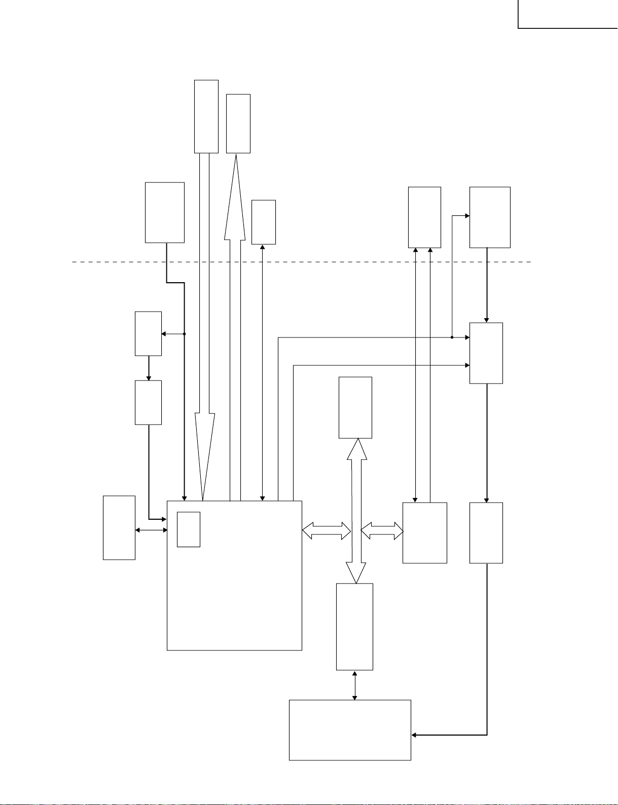
8-3. Block diagram of card unit
MSP
DC/DC
converter
IC704
4V/6V
Reg
IC5409
3.3V/5V
DA150
IC5201
Audio DSP
Data bus
5V/3.3V conversion
IC5401-IC5406
PCMCIA
Card
DM270
(IC5001)
Video DSP
DSP
1.5V
64M SDRAM
IC5006
1.5V
Reg
IC5004
DC/DC
converter
3.3V
Video decoder
(VPC) IC8801
LCD
controller
TVCPU
8 bit video, CLK, H, V (ITU-R 656)
8 bit video, CLK, H, V (ITU-R 656)
UART
4V/6V switching signal
ON/OFF
16 bit address
16 bit data
I
2
S (for recording)
I
2
S (for playing)
PC card block Main
32M FLASH
IC5003
LC-15B5M
21
Page 22
LC-15B5M
• PCMCIA card Used at 5V/3.3V
• DM270 (IC5001) CPU, DSP , DMAC, OSD, NTSC encoder: system control, OSD display, video encoding/decoding
Used at 3.3V (1.5V for DSP)
• DA150 (IC5201) Audio encoding/decoding
• 32M FLASH (IC5003) Storing the program for DA150 and DM270
• 64M SDRAM (IC5006) Used for temporary data storage and for image data compression and expansion.
• Reg (IC5409) Conversing 4V/6V to 3.3V/5V for PCMCIA
• Reg (IC5004) Conversing 3.3V to 1.5V for DSP in DM270
"Tips"
1) With this product, showing images recorded with PC or DSC enables you to check the playing system.
2) With PC, showing images recorded with this product enables you to check the recording system.
3) Video is played at the rate in sync with IIS CLOCK signals from audio circuit. For example, if the IIS CLOCK
signals fail to reach the card playing circuit for some reason, the video is played at the lowest rate and is shown
in slow motion.
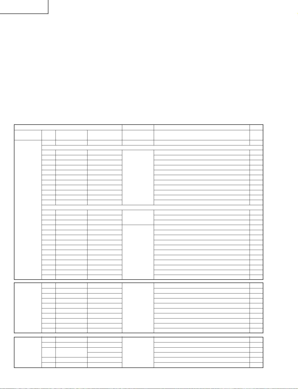
Major input/output terminals on the card system
Card side
IC (connector) Pin No. LSI terminal name Connection diagram Types of signals Explanation for signals I/O
name signal name
DM270 B3.3V_CARD1A B3.3V_CARD1A Power supply Power supply 3.3V for DM270 I
(IC5001)
103 VIN VIN V signal from VPC to DM270 I
102 HIN HIN H signal from VPC to DM270 I
100 LLC2 (CLK) LLC2 Clock signal from VPC to DM270 I
112 YIN0 YIN0 Data signal 0 from VPC to DM270 I
111 YIN1 YIN1 Data signal 1 from VPC to DM270 I
110 YIN2 YIN2 Video input/output Data signal 2 from VPC to DM270 I
109 YIN3 YIN3 Data signal 3 from VPC to DM270 I
108 YIN4 YIN4 Data signal 4 from VPC to DM270 I
107 YIN5 YIN5 Data signal 5 from VPC to DM270 I
106 YIN6 YIN6 Data signal 6 from VPC to DM270 I
105 YIN7 YIN7 Data signal 7 from VPC to DM270 I
55 RESET RESET Data Reset signal from TV microprocessor to DM270 I
10 CA_DOUT DOUT communication Data signal from TV microprocessor to DM270 I
11 DIN DIN Data signal from DM270 to TV microprocessor I
70 VOUT VOUT V signal from DM270 to IP O
69 HOUT HOUT H signal from DM270 to IP O
68 CKOUT CKOUT Clock signal from DM270 to IP O
81 YOUT0 YOUT0 Data signal 0 from DM270 to IP O
77 YOUT1 YOUT1 Data signal 1 from DM270 to IP O
76 YOUT2 YOUT2 Video input/output Data signal 2 from DM270 to IP O
75 YOUT3 YOUT3 Data signal 3 from DM270 to IP O
74 YOUT4 YOUT4 Data signal 4 from DM270 to IP O
73 YOUT5 YOUT5 Data signal 5 from DM270 to IP O
72 YOUT6 YOUT6 Data signal 6 from DM270 to IP O
71 YOUT7 YOUT7 Data signal 7 from DM270 to IP O
P5003 1 I2S_WS S_WS I2S word strobe L: Right audio input / H: Left audio input I
2 GND
3 I2S_CL S_CL Clock for I2S serial data transmission timing I
4 GND
5 I2SDA_OUT S_DO Audio input/output Audio data input from TV main unit I
6 GND
7 I2SDA_IN1 S_DI In card mode: Card Audio / Not in card mode: Shutter sound O
8 GND
9 I2SDA_IN2 SH_DI
10 GND
Reg 1 IN B4V/6V1_1A 4V/6V output from DC/DC converter to Reg O
(IC5409) 2 SW B4V/6V1_1A ON/OFF switch I
3 OUT V5EN Power supply 3V power input from DC/DC converter to Reg I
V3EN 5V power input from DC/DC converter to Reg I
4 ADJ For adjustment
5 GND GND GND
22
Page 23
LC-15B5M
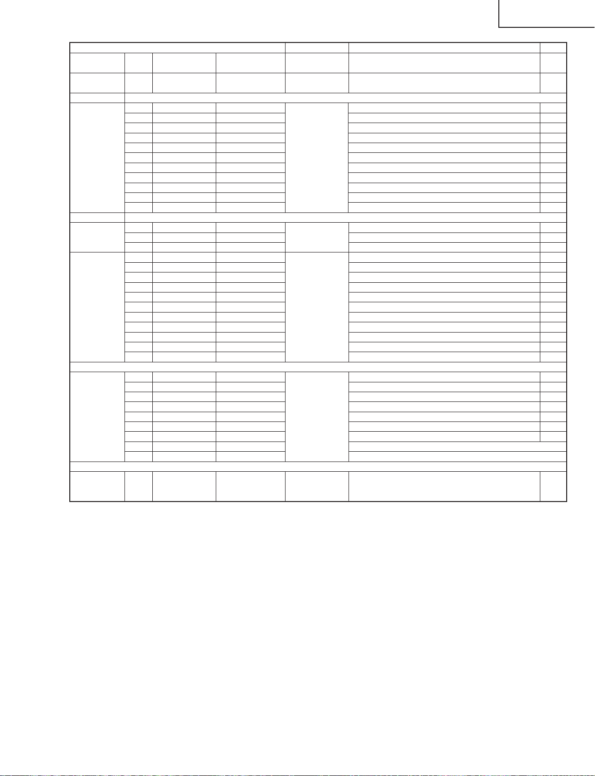
Main Side
IC (connector) Pin No. Terminal name Signal name Types of signals Explanation for signals I/O
name
P701 9 3.3V (SUB) B3.3V2A Power supply Power supply 3.3V for DM270
(NA215WJ)
VPC 57 VS VPC_VS V signal from VPC to DM270 O
(Video decoder) 56 MSY/HS VPC_HS H signal from VPC to DM270 O
IC8801 27 LLC2 LLC2 Clock signal from VPC to DM270 O
40 Y0 VPC_YIN0 Data signal 0 from VPC to DM270 O
39 Y1 VPC_YIN1 Data signal 1 from VPC to DM270 O
38 Y2 VPC_YIN2 Video input/output Data signal 2 from VPC to DM270 O
37 Y3 VPC_YIN3 Data signal 3 from VPC to DM270 O
34 Y4 VPC_YIN4 Data signal 4 from VPC to DM270 O
33 Y5 VPC_YIN5 Data signal 5 from VPC to DM270 O
32 Y6 VPC_YIN6 Data signal 6 from VPC to DM270 O
31 Y7 VPC_YIN7 Data signal 7 from VPC to DM270 O
TV 83 CARDRST RESET
microprocessor 35 SUB_DOUT DOUT Rese
(IC2201) 36 SUB_DIN DIN Data signal from DM270 to TV microprocessor I
I/P conversion 207 VS_P2 VD_VS V signal from DM270 to IP I
IC 208 HS_P2 VD_HS H signal from DM270 to IP I
195 IN_CLK_P2 VD_CKO Clock signal from DM270 to IP I
196 P2_0 VPC_0 Data signal 0 from DM270 to IP I
199 P2_1 VPC_1 Data signal 1 from DM270 to IP I
200 P2_2 VPC_2 Video input/output Data signal 2 from DM270 to IP I
201 P2_3 VPC_3 Data signal 3 from DM270 to IP I
202 P2_4 VPC_4 Data signal 4 from DM270 to IP I
203 P2_5 VPC_5 Data signal 5 from DM270 to IP I
204 P2_6 VPC_6 Data signal 6 from DM270 to IP I
205 P2_7 VPC_7 Data signal 7 from DM270 to IP I
MSP 5 I2S_WS S_WS I2S word strobe L: Right audio input / H: Left audio input O
(
Audio processor
DC/DC
converter B4V/6V1_1A B4V/6V1_1A Power supply 4V/6V output from DC/DC converter to Reg O
IC704
)
4 I2S_CL S_CL Clock for I2S serial data transmission timing O
6 I2SDA_OUT S_DO Audio input/output Audio data input from TV main unit O
7 I2SDA_IN1 S_DI In card mode: Card Audio / Not in card mode: Shutter sound I
Data communication,
t
Reset signal from TV microprocessor to DM270 O
Data signal from TV microprocessor to DM270 O
Abolished
23
Page 24
LC-15B5M
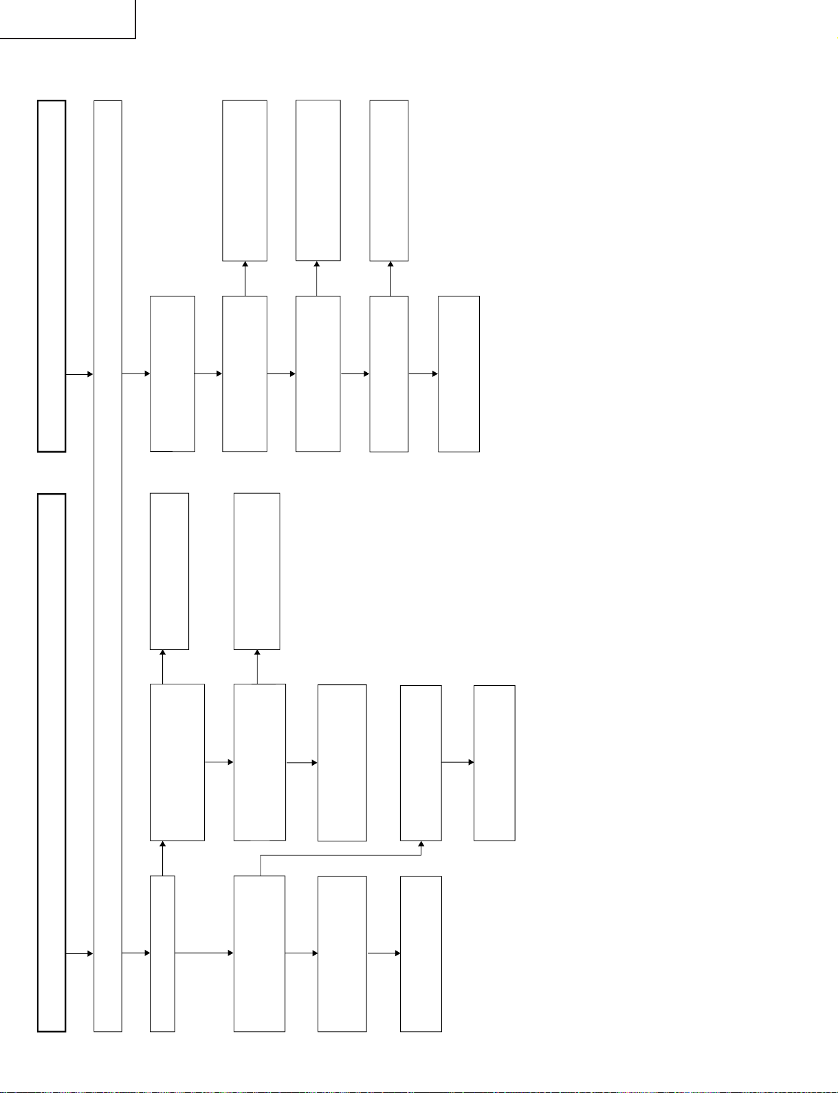
No picture and sound
Check all the settings on the microprocessor's adjust process menu.
Fluorescent light in trouble
Are F3701 and F3702 normal?
YES
YES
YES
YES
YES
YES
NO
YES
NO
NO
NO
NO
NO
YES
YES
NO
Does the load side keep
normal circuits when F3701
and F3702 are disconnected?
Are F3701, F3702, F6501,
and F6502 normal?
Do Q6502 and Q6505 keep
normal circuits?
Check Q6502, Q6505 and
their peripheral circuits.
Check S4053 and the
connecting cables.
Check the connecting cables
and the peripheral circuits of
J3701.
Are pins (14) of IC701 thru
IC704 normal? (13.5V~2.05V)
Are pin (121) of IC1201"H"?
Are the oscillation waves from
the primary sides of T6500,
T6502 normal?
Check and replace the
fluorescent light.
Check the connecting cables
and the peripheral circuits of
Q6500 thru Q6505.
Check that line, IC1201 and
their peripheral circuits.
Are +34V, +9V and +5V on the
secondary side output at T701
normal?
Are the oscillation waveform
at T701's primary side as
specified?
Check the secondary-side
load of T701.
Check the load side.
Do Q715, Q716, S4053 and
the peripheral circuits on the
primary side of T701 keep
normal circuits?
Replace F3701 and F3702.
TROUBLE SHOOTING TABLE
24
Page 25
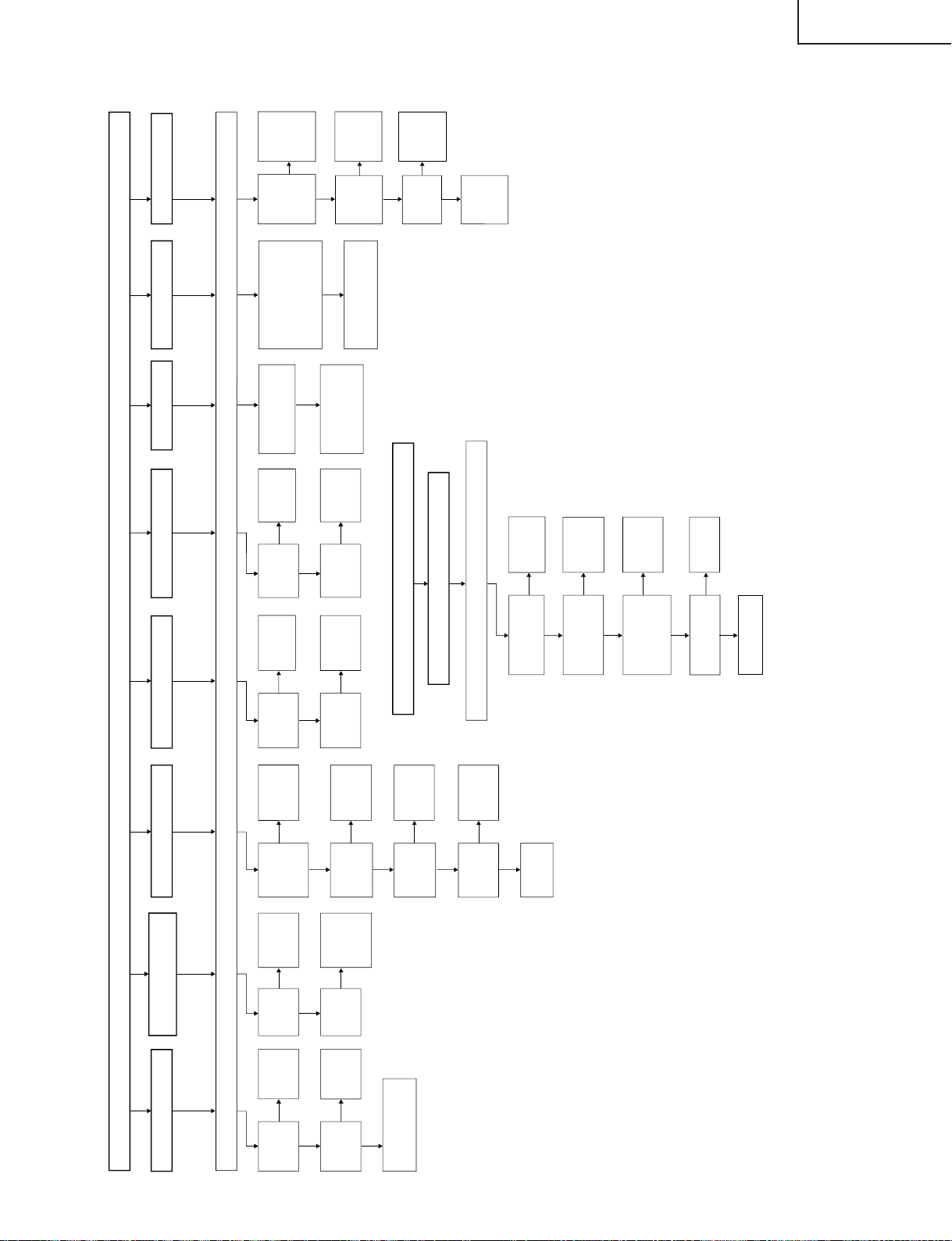
No picture (1/2)
No picture at all
No TV , VIDEO 1, VIDEO 2
and VIDEO 3 outputs
No TV output
No VIDEO 1 output
No VIDEO 2 output
Check all the settings on the microprocessor's adjust process menu.
NO
NO
NO NO NO NO
NO
NO
NO
NO
NO
NO
YES YES
YES
YES YES
No S-VIDEO output
No COMPONENT output
YES
YES
YES
YES
No picture (2/2)
No PC card output
Check all the settings on the microprocessor's adjust process menu.
NO
NO
NO
NO
YES
YES
YES
YES
Are the
input/output
at IC8801
normal?
Are the
input/output
at IC3401
normal?
Check
IC3401 and
its peripheral
circuits.
Check the
power supply
line.
Is the input
at pin (1) of
IC3401
normal?
Is the input
at pin (8) of
IC3401
normal?
Is the input at pins
(71) and (72) of
IC8801 normal?
Is the input at pins (4), (5),
(6) and (75) of IC8801
normal? (D1)
Is the input at pins (43),
(48) and (54) of IC8701
normal? (D2)
Check the DVD_Y, CB and
CR lines of J2205 and their
peripheral circuits.
Check the SY and SC
lines of J3401 and
their peripheral
circuits.
Is the output
at IC3401
normal?
Is the output
at IC3401
normal?
Check
IC3401 and
its peripheral
circuits.
Check
IC3401 and
its peripheral
circuits.
Check that
line.
Check that
line.
Is the voltage
at pins (6),
(7) and (9) of
the tuner
normal?
Is the output
at pin (19) of
the tuner
normal?
Is the input
at pin (47) of
IC3401
normal?
Is the output
at IC3401
normal?
Check that
line.
Check
IC3401 and
its peripheral
circuits.
Are the card
medium and its files
normal?
Check the
medium and
its files.
Is the output at
IC8602 and IC8603
normal?
Check that
line.
Replace the card
unit.
Is the voltage at
pins (2) and (3) of
P5001 in the PC
card unit normal?
Check the
power supply
line.
Is the voltage at
pins (1), (2) and (3)
of IC5004 and at
pins (1), (2) and (3)
of IC5005 normal?
Check the
power supply
line.
Check the
tuner and its
peripheral
circuits.
Check that
line.
Is the input
at pin (73)
of IC8801
normal?
Check the
AV1 line of
IC8801 and
its peripheral
circuits.
Are the
input/output
at IC1201
normal?
Check the voltage and
waves at the liquid
crystal panel.
Check
IC1201 and
its peripheral
circuits.
Check
IC8801 and
its peripheral
circuits.
Are inputs
and outputs
of Q1604,
Q1606 and
Q1608 as
specified?
Check
Q1604,
Q0606,
Q1608 and
its
peripheral
parts.
Is output at
pins
(57)~(59) of
IC1601
normal?
Check the
R, G and B
line.
Is input at
pin (21) of
IC1601
normal?
Check V2V0
line and its
peripheral
parts.
Check
IC1601 and
its
peripheral
parts.
No TELETEXT output
No
Yes
Yes
No
No
Yes
TROUBLE SHOOTING TABLE (Continued)
LC-15B5M
25
Page 26
LC-15B5M
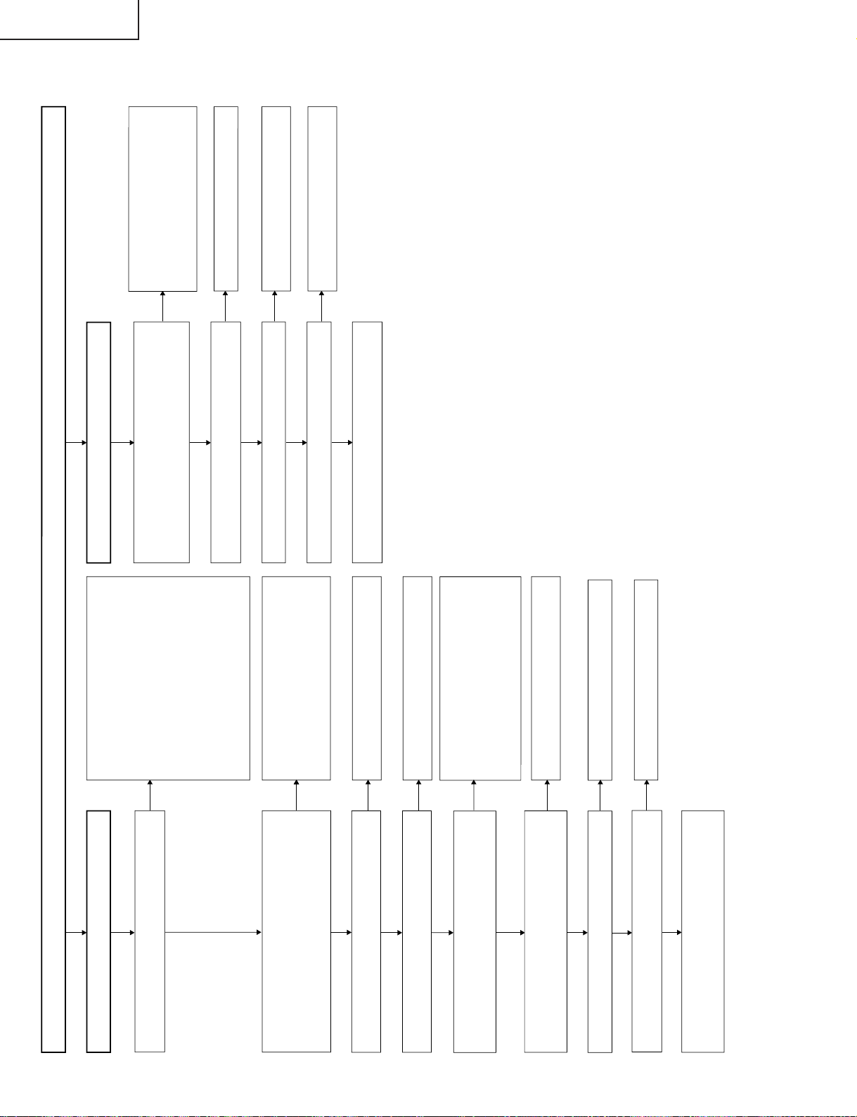
No sound
No sound from speakers
YES
YES
YES
YES
YES
YES
YES
YES
NO
YES
YES
YES
YES
NO
NO
NO
NO
NO
NO
NO
NO
NO
Check the following.
1 No audio output from TV ... Check the
peripheral circuits of Q3202 and TU3000.
2 No audio output from VIDEO 1 input ...
Check J3402 thru pins (2) and (4) of
IC3401.
3 No audio output from VIDEO 2 input ...
Check J3409 thru pins (22) and (24) of
IC3401.
4 No audio output from VIDEO 3 input ...
Check J3403 thru pins (9) and (11) of
IC3401.
5 No audio output from COMPONENT input ...
Check J3406 and J3404 thru pins (46) and
(48) of IC3401.
Is there the audio output in any input mode (TV, VIDEO 1/2
and COMPONENT)?
Check the following.
1
Is the monitor output setting at "Audio fixed"?
2
Is the sound volume loud enough?
3
Is the mute mode released?
4
Are the headphones unplugged?
Is the power supply voltage at each circuit normal?
Pin (8) of IC3301 and pin (39) of IC3201 Approx. +8V
Pins (11), (12), (13), (65) and (66) of IC3201 Approx. +5V
No sound from monitor output
Is there the audio signal output at pins (33)(Rch) and
(34)(Lch) of IC3201?
Is pin (55) of IC2001 "H"?
Is the signal from the Q2203 collector "L"?
Check pins (33)(Rch) and (34)(Lch) of IC3201 thru pins
(4)(Lch) and (2)(Rch) of J3404.
Check the following.
1
Is there the audio output from speakers?
2
Is the monitor output connected correctly?
3
Is the mute mode released?
Check the following.
1
Go to "No Audio from Speakers".
2
Connect the monitor output correctly.
3
Release the mute mode.
Check the peripheral circuits of IC3201.
Check pin (4) of J4021 thru pin (58) of
IC2001.
Check pin (55) of IC2001 thru Q2203, and
Q3401, 3402.
Is there the control signal input at each pin of IC3201?
Pin (2) of IC3201 SCL1
Pin (3) of IC3201 SDA1
Are the oscillation waves from pins (71) and (72) of IC3201
normal?
Check pins (29) and (30) of IC2001 thru pins (2)
and (3) of IC3201.
NO
Is the voltage at pin (7) (power input terminal) of IC3304 as
specified (about +12V)?
Check the AC adaptor and the line between AC
adaptor and pin (7) of IC3304.
NO
Is the voltage at pin (5) (standby control terminal) of
IC3304 as specified (about +2.8V)?
Check the line between pin (56) of IC2001 and
pin (5) of IC3304.
Check the peripheral circuits of X3201.
Is there the audio signal output at pins (27)(Rch) and
(28)(Lch) of IC3201?
Check pins (27)(Rch) and (28)(Lch) of IC3201 thru pins
(7)(Rch) and (1)(Lch) of IC3304, and the peripheral circuits
of IC3301.
Check the peripheral circuits of IC3201.
Recheck the following.
1
Set the monitor output to "Audio fixed".
2
Increase the sound volume.
3
Release the mute mode.
4
Unplug the headphones.
Check the following.
+8V system ... Check the peripheral circuits of
Q3711 thru pin (8) of IC3301 and
pin (39) of IC3201.
+5V system ... Check the T701 output B5V500MA
line thru each +5V input pin of
IC3201.
TROUBLE SHOOTING TABLE (Continued)
26
Page 27
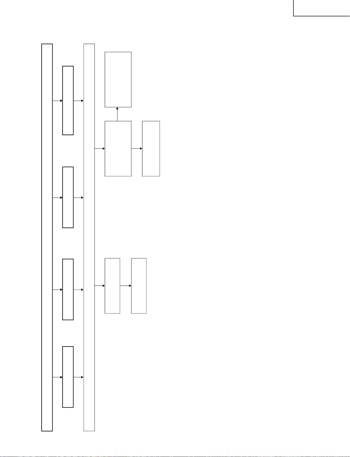
TROUBLE SHOOTING TABLE (Continued)
No Colours
No TV colours No VIDEO colours
No S-VIDEO colours No COMPONENT colours
Check all the settings on the microprocessor's adjust process menu.
YES
NO
NO
Is the input at pin (71) of
IC8801 normal?
Is the input at pins (4) and
(6) of IC8801 normal? (D1)
Is the input at pins (43) and
(54) of IC8701 normal?
(D2)
Check the CB and CR
lines of J2205 and their
peripheral circuits.
Check the output at
IC8801 (D1), output at
IC8701 (D2), input/output
at IC1201 and their
peripheral circuits.
Check the SC line of J2201
and its peripheral circuits.
LC-15B5M
27
Page 28
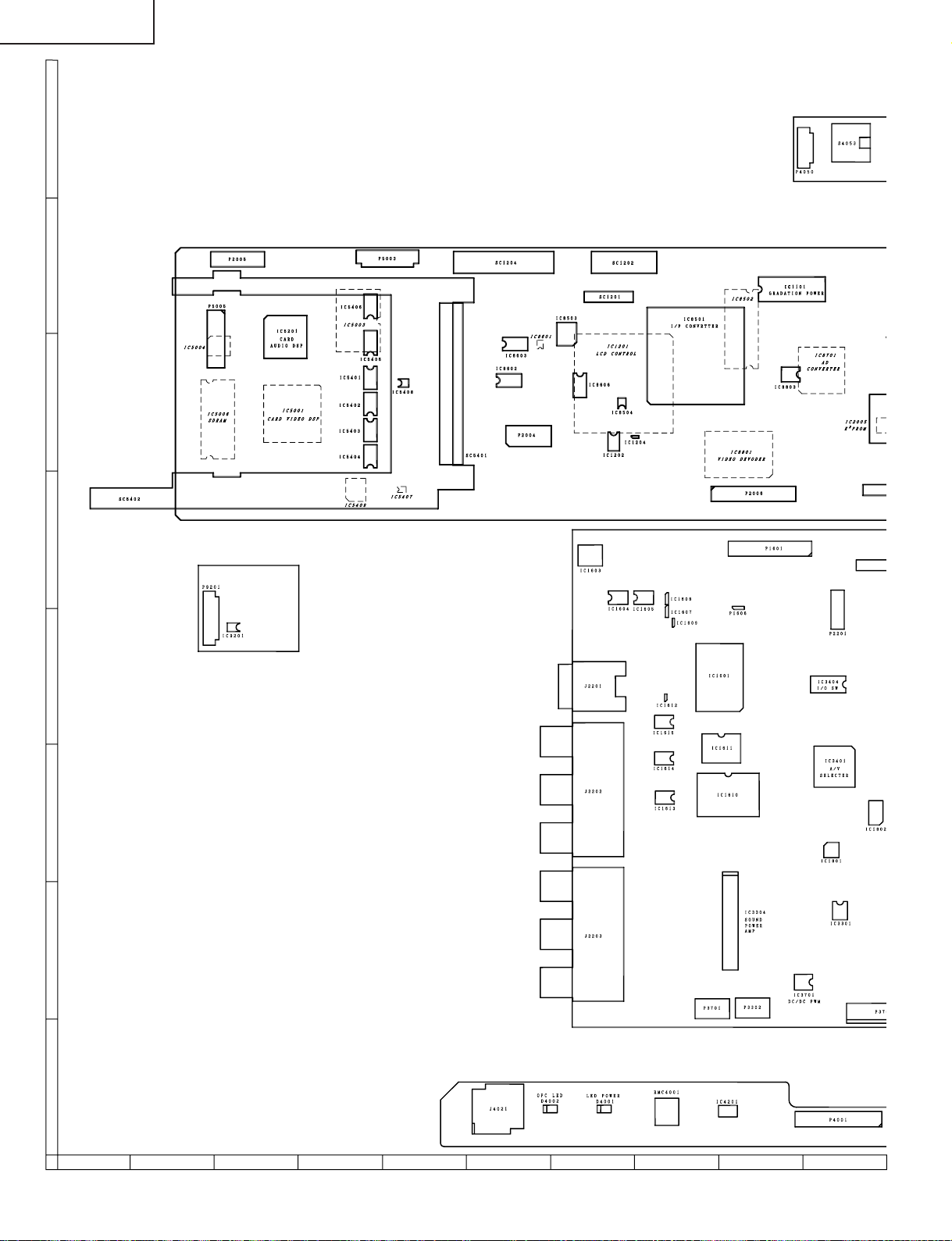
LC-15B5M
CHASSIS LAYOUT
H
MAIN Unit
G
F
E
D
C
B
CARD LED Unit
R/C, LED Unit
A
87109654321
28
Page 29
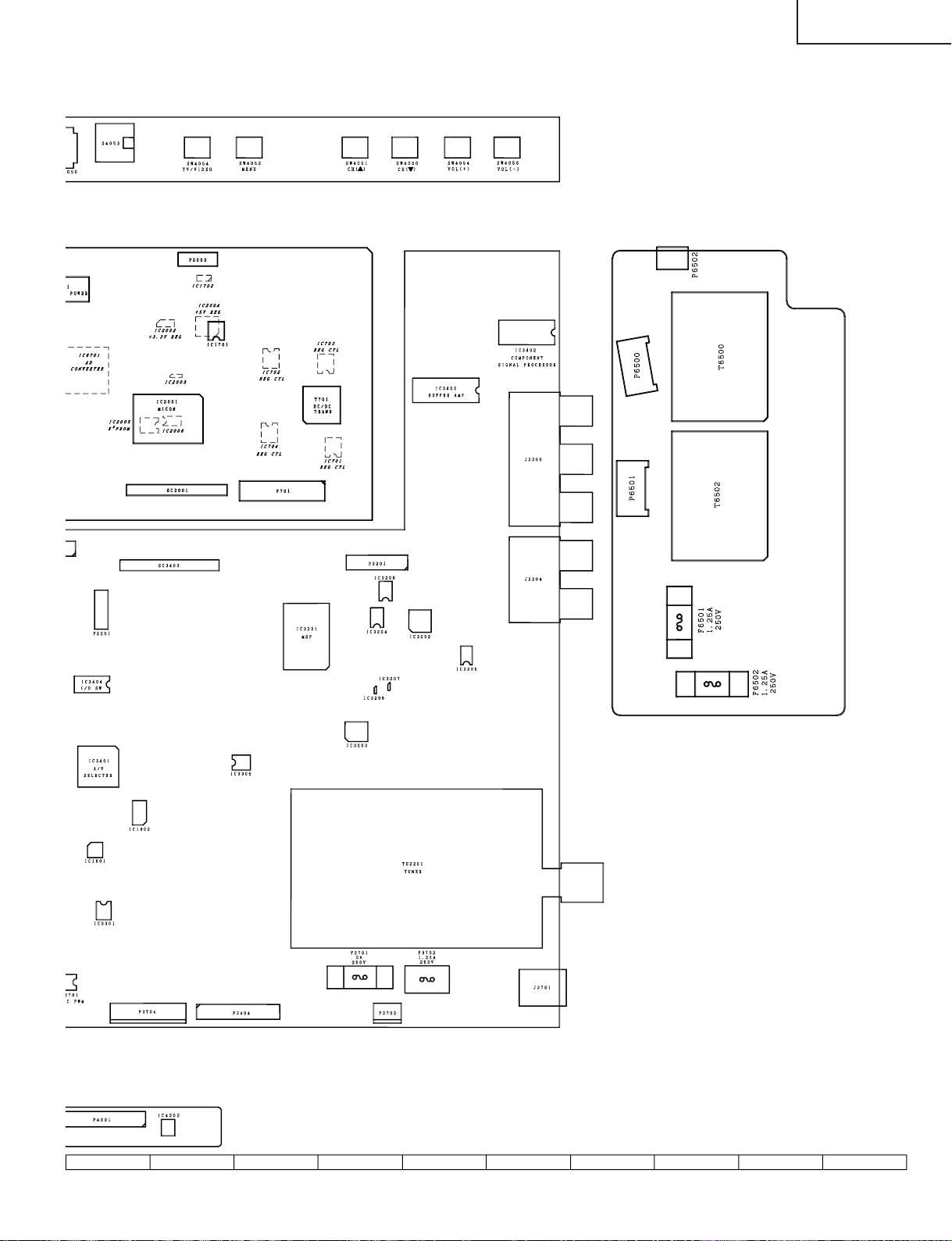
OPERATION Unit
LC-15B5M
ANALOG Unit
INVERTER Unit
29
1716 1918151413121110
Page 30
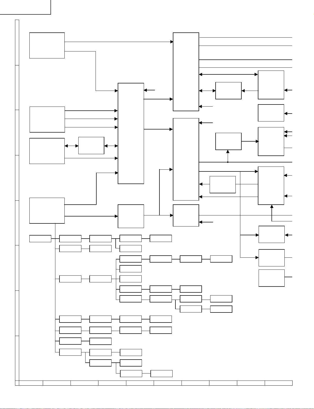
LC-15B5M
-
BLOCK DIAGRAM
H
TUNER
TU2201
SIF
MSP
IC3201
DA150
IC5201
32M
FLASH ROM
IC5003
DA270
IC5001
TELETEXT
CPU
IC1601
COPY
GARD
IC1801
AUDIO
VIDEO
S-VIDEO
AUDIO
AUDIO
I/O SW
IC3404
VIDEO
AUDIO
Y,PB,PR
VIDEO
+5V
I2C
YC
A/V SW
IC3401
480I(Y,PB,PR)
FILTER
IC3403
IC2002 +3.3V
480P(Y,PB,PR)
VPC
IC8801
ADC
IC8701
EQ
IC3202
2
C
I
2
C
I
SW
IC8603
V-OUT
RGB AMP
Q1604,Q1606
Q1608
TX_FB
I2C
ITU656
G
AV1
INPUT
J2202
F
AV2
INPUT/OUTPUT
J2203
E
COMPONENT
INPUT
J2205
D
DC+12V IC2004
IC1702
C
IC701
+3.3V
T701
C3714
-12V
-7V
+5V
+9V
+35V IC3701
IC1701 Q1703
Q3711 +8V
Q3710
Q3709
-7.5V
+31V
+23V
SYNC-SEPA
IC8803
RESET
IC2003
C
B
IC703
IC704
IC702
IC1603
A
+3.3V IC8503 +1.8V
4V/6V IC5409 3.3V/5V
+5V
IC1604
IC1605
+2.5V
+3.3V
IC1802
+1.8V
87109654321
30
Page 31

LC-15B5M
Y
DA150
IC5201
32M
ASH ROM
IC5003
DA270
IC5001
ELETEXT
CPU
IC1601
SW
IC8602
4M FLASH
IC1610
2M SRAM
IC1611
HP AMP
IC3305
SOUND
POWER AMP
IC3304
5V/3.3V
CONVERTER
IC5401-6
64M
SDRAM
IC5006
64M
SDRAM
IC8502
FLI2310
IC8501
PC3C1A
CARD
SC5401
R,G,B
OSD
CONTROL
LCD
CONTROLLER
IC1201
HP JACK
SP_L/SP_R
LCD
PANEL
J4021
SC1201
SC1202
SC1204
480P (R0~7, G0~7, B0~7)
C-SYNC
RXD/TXD
2
I
C
KEY
SW
MICON
IC2001
R/C
RECEIVER
EEPROM
IC2005
COPY
GARD
IC1801
NC-SEPA
IC8803
RESET
IC2003
GRAD
IC1101
COMMON
Q1105
Q1106
INVERTER
DRIVE
Q6500,Q6501
Q6503,Q6504
DC/AC
COMMON
T6500
T6502
LAMP
ERROR
DETECTER
BACKLIGHT
P6500
P6501
31
1716 1918151413121110
Page 32

LC-15B5M
OVERALL WIRING DIAGRAM
H
G
F
E
D
C
B
A
87109654321
32
Page 33

LC-15B5M
33
1716 1918151413121110
Page 34

LC-15B5M
DESCRIPTION OF SCHEMATIC DIAGRAM
VOLTAGE MEASUREMENT CONDITION:
1. The voltages at test points are measured on
exclusive AC adaptor and the stable supply voltage
of AC 120V. Signals are fed by a colour bar signal
generator for servicing purpose and the above
voltages are measured with a 20k ohm/V tester.
INDICATION OF RESISTOR & CAPACITOR:
RESISTOR
1. The unit of resistance “Ω” is omitted.
(K=kΩ=1000 Ω, M=MΩ).
2. All resistors are ± 5%, unless otherwise noted.
(J= ± 5%, F= ± 1%, D= ± 0.5%)
3. All resistors are 1/16W, unless otherwise noted.
4. All resistors are Carbon type, unless otherwise
noted.
C : Solid
S : Oxide Film T : Special
N : Metal Coating
CAPACITOR
1. All capacitors are µF, unless otherwise noted.
(P=pF=µµF).
2. All capacitors are 50V, unless otherwise noted.
3. All capacitors are Ceramic type, unless otherwise
noted.
(ML): Mylar (TA): Tantalum
(PF): Polypro Film (ST): Styrol
W
: Cement
CAUTION:
This circuit diagram is original one, therefore there may be a
slight difference from yours.
IMPORTANT SAFETY NOTICE:
PARTS MARKED WITH “å” ( ) ARE
IMPORTANT FOR MAINTAINING THE SAFETY OF
THE SET. BE SURE TO REPLACE THESE PARTS
WITH SPECIFIED ONES FOR MAINTAINING THE
SAFETY AND PERFORMANCE OF THE SET.
34
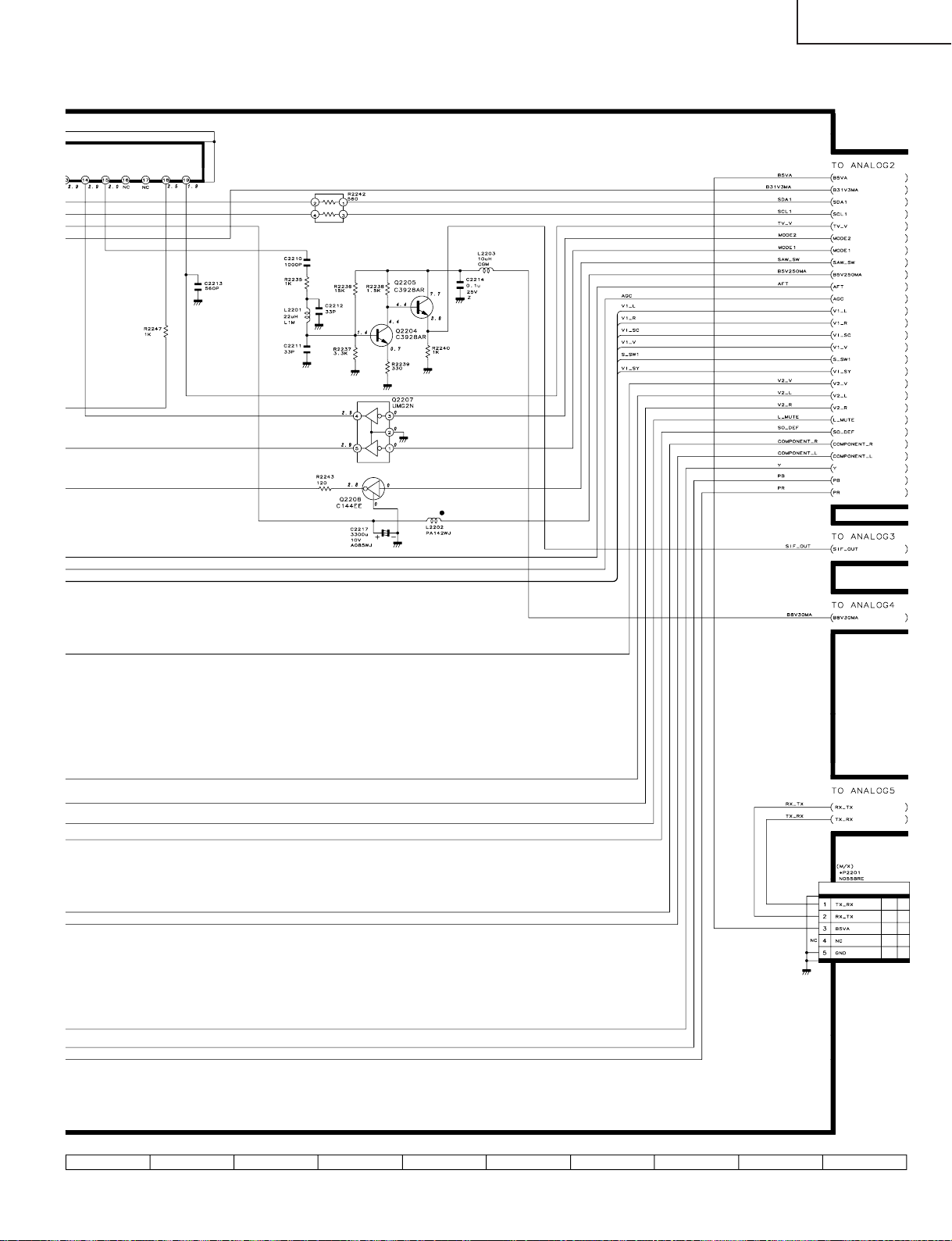
Page 35

LC-15B5M
654321
A
B
C
D
E
F
G
H
SCHEMATIC DIAGRAM
Ë
OPERATION Unit
35
Page 36

LC-15B5M
Ë
MAIN Unit-1/12
H
G
F
E
D
C
B
A
87109654321
36
Page 37

LC-15B5M
37
1716 1918151413121110
Page 38

LC-15B5M
Ë
MAIN Unit-2/12
H
G
F
E
D
C
B
A
87109654321
38
Page 39

LC-15B5M
39
1716 1918151413121110
Page 40

LC-15B5M
Ë
MAIN Unit-3/12
H
G
F
E
D
C
B
A
87109654321
40
Page 41

LC-15B5M
41
1716 1918151413121110
Page 42

LC-15B5M
Ë
MAIN Unit-4/12
H
G
F
E
D
C
B
A
87109654321
42
Page 43

LC-15B5M
43
1716 1918151413121110
Page 44

LC-15B5M
Ë
MAIN Unit-5/12
H
G
F
E
D
C
B
A
87109654321
44
Page 45

LC-15B5M
45
1716 1918151413121110
Page 46

LC-15B5M
Ë
MAIN Unit-6/12
H
G
F
E
D
C
B
A
87109654321
46
Page 47

LC-15B5M
47
1716 1918151413121110
Page 48

LC-15B5M
Ë
MAIN Unit-7/12
H
G
F
E
D
C
B
A
87109654321
48
Page 49

LC-15B5M
49
1716 1918151413121110
Page 50

LC-15B5M
Ë
MAIN Unit-8/12
H
G
F
E
D
C
B
A
87109654321
50
Page 51

LC-15B5M
51
1716 1918151413121110
Page 52

LC-15B5M
Ë
MAIN Unit-9/12
H
G
F
E
D
C
B
A
87109654321
52
Page 53

LC-15B5M
53
1716 1918151413121110
Page 54

LC-15B5M
Ë
MAIN Unit-10/12
H
G
F
E
D
C
B
A
87109654321
54
Page 55

LC-15B5M
55
1716 1918151413121110
Page 56

LC-15B5M
Ë
MAIN Unit-11/12
H
G
F
E
D
C
B
A
87109654321
56
Page 57

LC-15B5M
57
1716 1918151413121110
Page 58

LC-15B5M
Ë
MAIN Unit-12/12
H
G
F
E
D
C
B
A
87109654321
58
Page 59

LC-15B5M
59
1716 1918151413121110
Page 60

LC-15B5M
Ë
ANALOG Unit-1/5 (LC-15B5M)
H
G
F
E
D
C
B
A
87109654321
60
Page 61
LC-15B5M
61
1716 1918151413121110
Page 62

LC-15B5M
Ë
ANALOG Unit-1/5 (LC-15B5M(X))
H
G
F
E
D
C
B
A
87109654321
62
Page 63

LC-15B5M
63
1716 1918151413121110
Page 64

LC-15B5M
Ë
ANALOG Unit-2/5
H
G
F
E
D
C
B
A
87109654321
64
Page 65

LC-15B5M
65
1716 1918151413121110
Page 66

LC-15B5M
Ë
ANALOG Unit-3/5
H
G
F
E
D
C
B
A
87109654321
66
Page 67

LC-15B5M
67
1716 1918151413121110
Page 68

LC-15B5M
Ë
ANALOG Unit-4/5
H
G
F
E
D
C
B
A
87109654321
68
Page 69

LC-15B5M
69
1716 1918151413121110
Page 70

LC-15B5M
Ë
ANALOG Unit-5/5
H
G
F
E
D
C
B
A
87109654321
70
Page 71

LC-15B5M
71
1716 1918151413121110
Page 72

LC-15B5M
Ë
R/C, LED Unit
H
G
F
E
D
C
B
A
654321
72
Page 73
LC-15B5M
654321
A
B
C
D
E
F
G
H
Ë
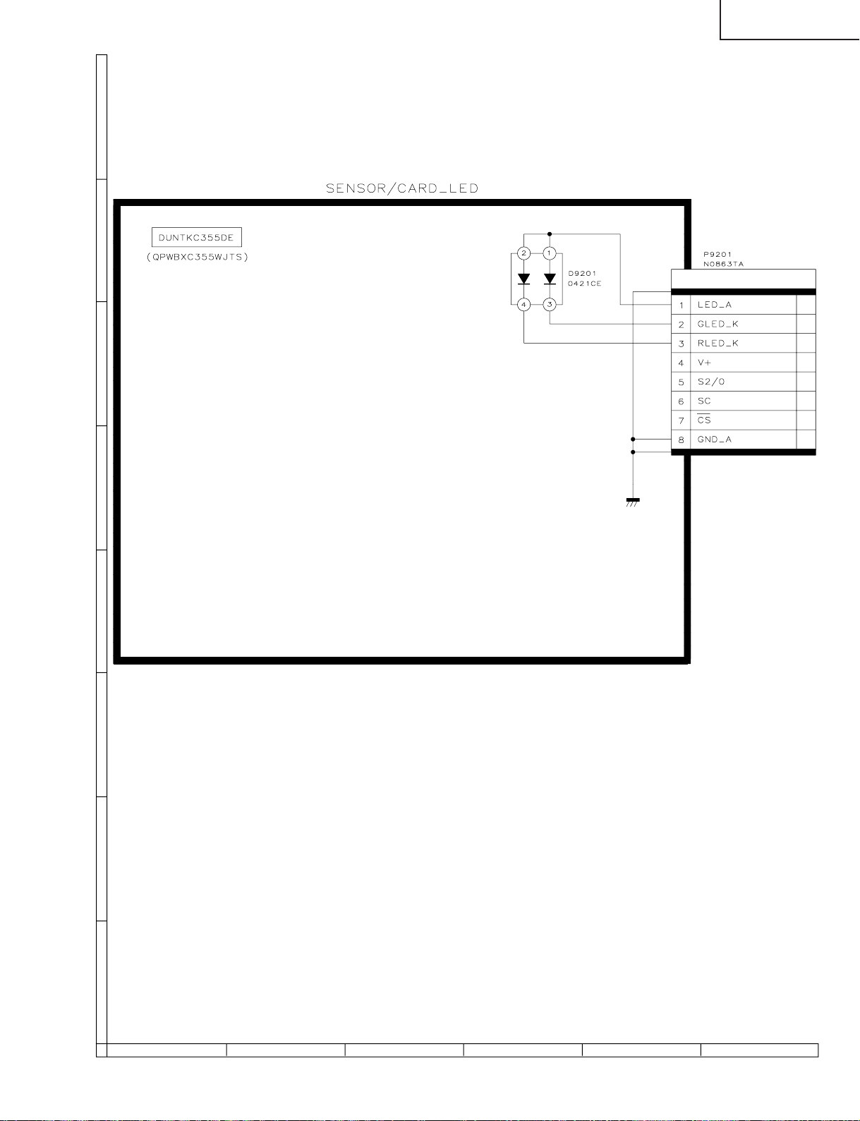
CARD LED Unit
73
Page 74

LC-15B5M
Ë
INVERTER Unit
H
G
F
E
D
C
B
A
654321
74
Page 75

LC-15B5M
654321
A
B
C
D
E
F
G
H
PRINTED WIRING BOARD ASSEMBLIES
OPERATION Unit (Side-A)
(QPWBXC353WJN2)
P4050
S4053
D4050 D4052
D4051
SW4054
R4052
R4051
SW4052
SW4051
R4050
OPERATION Unit (Chip Parts Side-A)
(QPWBXC353WJN2)
SW4050
R4053
SW4055
SW4056
R/C, LED Unit (Side-A)
(QPWBXC354WJN2)
R4001
D4004
R4002
D4003
Q4004
Q4001
D4001
Q4002
R4003 R4004
D4006 R4005
D4002
Q4003
J4021
C4203
IC4201
C4201
C4202
R4006
C4001
RMC4001
C4205 C4206
IC4202
R4008
R4007
C4204
P4001
X4000
D4005
SLD4001
R/C, LED Unit (Chip Parts Side-A)
(QPWBXC354WJN2)
D9201
R9201
P9201
IC9201
C9201
CARD LED Unit (Side-A)
(QPWBXC355WJN2)
CARD LED Unit (Chip Parts Side-A)
(QPWBXC355WJN2)
75
Page 76

LC-15B5M
C1210
C8501
H
G
F
E
MAIN Unit (Side-A)
C5018
C5013
C5017
R5204
SC5402
CK5091
R5058
CK5085
C5012
R5012
IC5201
C5204
TP5401
C5205
R5205
R5214
CK5084
C5207
C5010
CK5003
R5016
CK5077
C5016
CK5082
C5206
CK5060
CK5081
R5007
C5203
CK5110
C5008
R5206
R5211
CK5058
CK5078
C5007
CK5059
R5460
R5209
R5208
R5207
R5210
R5061
R5001
R5458
CK5076
R5008
X5201
R5060
C5006
R5470
C5209
C5210
C5208
CK5063
C5003
R5025
R5212
R5020
R5004
R5017
C5402
C5404
R5438
C5405
R5454
C5406
IC5406
IC5405
IC5401
IC5402
IC5403
IC5404
R5094
R5099
P5003
C5401
C5403
R5213
R5437
R5093
R5435 R5434 R5436
R5433
R5455 R5453
R5092
R5457 R5456
IC5408
R5056
R5055
R5090
R5091
R5450
R5449
R5452 R5451
SC5401
TP5402
TP5403
SC1204
C8604
C8605 R8607
IC8602
IC8603
SC1202
R8516
FB8505
FB8504
C8535 C8536
FB8501
C8516
C8512
X8501
C8508 R8514 C8511
C8509
C8507
R8504
R8507
R8505
R8506
C1207
R1216
IC1204
R1211
R1208 R1206
R8606
Q8603
FB1201
R8605
C8606
C8534
C1204
R8521
R8520
C1205
D8501
R1255
R8515
L8501
C8537
SC1201
L8502
C8540
C8515
C8531
IC1202
FB8506
C1216
C8525
C8517
C8513
IC8504
C8542
R8610R8608
IC8503
C1229
R8613
C1226
C1232
P2004
R8609
C1221
IC8606
IC1207
P2005
D
R5019
C5201
C5202
CK5201
P5005
C
R5203
R5201
R5202
B
D5001
P5004
TP2001
TP2068
A
MAIN Unit (Chip Parts Side-A)
87109654321
76
Page 77

LC-15B5M
C8515
C8531
C8540
201
02
1
7
IC1202
FB8506
C1216
C8513
IC8504
SC1202
C8525
C8517
D704
FB714
TP702
FB701
C761
D703
FB709
L705
Q716
FB712
C735
D707
C760
C759
FB707
Q721
C764
FB710
C734
L702
Q715
C746
Q713
D702
FB702
C743
FB708
L704
Q714
C733
P701
TP707
C732
D701
C744
L701 Q712
C742
FB703
D711
C766
R778
C747
T701
D706
D709
FB705
FB706
R796
TP701
R777
R795
C758
C756
C753
C754
D708
C751 C750
D705
FB704
D1107
R8834
R8503
L8807
R8502
C8524
C8831
R8835
R8501
C8828
C8806
D1106
R8518
C8505
L8808
TP2069
R8517
C8522
C8521C8520R8516
FB8505
FB8504
C8535 C8536
FB8501
C8516
C8512
X8501
C8508 R8514 C8511
C8509
C8507
TP2068
C1210
C8501
C8502
C1211
C8816
C1207
R8504
R1211
R1216
R8507
IC1204
R8505
R8506
R1208 R1206
L8805
IC8501
FL1201
C8808
C8836
C8504
C8503
R8833
R8513
L8804
L8806
C8811
C8840
R8519
L8803
P2006
R8818 R8822
C8506
C8829
C8510
L8802 R8817 R8824
C8830
C8514
C8827
C8518 C8519
R8819 R8826
C8832
L8801
R1117
C8849 C8857 R8866
C8826
C8834
C8804
C8839
R8810
R8861
C1106
C1117
C1116
IC1101
C1104
C1119
R8812
R8809
IC8803
C8812
C8819
C8807
R8813
R8807
Q8802
C8851 C8854 R8863
R8862 C8852 R8814
C8850 C8855 R8865
C8837
R8860
R8859 C8835
R8821 R8870
R8808
R8805
C8802
C8803
Q8801
R1101
C1715
C8801 R8802 R8806
R8804
C1105
R1714
R8803
C1102
C8825 C8820
R8801
R1116
D1105
R1135
R1137
R1111 R11 34 R11 02 C110 7
C1112 R1127 R1136 R1103 R1112
C1714
R2056
R2074
R2066
R2049
R2100
Q2016
R2099
C1122
D1104
R1131
R1113
R1114
R1130
R1138
L1702
R2062
Q2007
R2061
R2076
R2083
R2082
R2087
R2075
R2079
C2014
R2072
R2101
Q2015
R2064
R2107
R2065
C2019
R2071
C1709
C2018
R2108 R2120
D1708
Q2017
Q2018
C1712
R1713
R1711
C1711
D1707
D2006
C2021
C2027
R2109
R2106 R2105
C2020
C2016
IC2001
R2060
R2068
R2103
R2057
TL2074
Q1705
R2058
R2111
FL2001
C1713
R2054
L1701
R2112
SC2001
R2053
R1708
R1709
R1710
Q1704
TL2073
R2051
R2114
R2052 C2015
R2050
R1712
D1706
R1706
R1707
C2013
Q1703
R2045
P2003
X2001
R1703
C1701
C1704
IC1701
R2041
R2040
R2037
R2102
R2032
C2007 C2008
C2006
D710
C1703R1705
L703
R2039
R2036
C741
TP703
C745
77
1716 1918151413121110
Page 78

LC-15B5M
C
1
2
H
G
F
E
MAIN Unit (Side-B)
TL2014
R2004
C2023
C2022
R2033
R2007
TL2060
TL2062
TL2013
D1701
R2013
C2001
R2008
C2012
TL2071
R2003R2015R2025
D1703
TL2059
C2026
TL2072
TL2056
TL2058
R2094R2020
IC2004
R2018
R2021
R2016R2022R2023
Q2004
TL2057
IC1702
R2044
R2026
Q2005
TL2015
TL2055
R2078
TL2052
TL2054
C1706
C2009
R2017
R2028
TL2053
TL2016
R2002
R2024
C2010
R2011
R2035
TL2051
TL2050
C1710
R2009
R2104
TL2049
TL2048
R2046
C2011
R2047
Q2001
TL2047
TL2017
C1707
C2004
D2001D2003
R2085
TL2045
TL2044
TL2046
Q2010
TL2043
R2043
R2048
TL2041
C1708
R2012
IC2003
R2086
R2096
R2027
C2002
IC2006
Q2014
TL2037
TL2039
TL2033
TL2040
TL2042
C2024
R2095
R2031
R2042
R2069
R1108
D1102
Q1104
C2003
IC2002
Q2006
Q2013
R2001
TL2035
TL2036
C2005
TL2038
Q1101
R2077
TL2031
R1126C1109R1104
R2115
C2017
D2005
TL2027
TL2032
R2070R2059R2055
TL2034
IC2005
R2098
R2029
TL2025
TL2029
D1101
C1115
R2067
R2063
Q2008
TL2023
TL2028
R1125
TL2030
C1101
R2084
C8716R8713
R8712
TL2021
TL2019
D1103
Q2012
C8719
C8712R8705C8717R8714
Q2003
TL2026
R2014
Q2002
R2006
Q1106
C8711R8704C8713C8714C8718
R2019
Q1702D1705
C1702
R2005
R1124
R1702
TL2018
R2073
R8703
Q1701
R1704
C8708
R8706
C1114
Q1105
C8720
FB8703
R8707
C8707
C8709
R1109
IC8701
C8706
R8701
R1105
R8702
R8711
Q8803
C8705
Q1102
C8710
C8818
C8703
C8809
C8814
R8816
R8811
C8715
R8837R8836
C1111
C8704
C8822C8821
C8813
C8815
C8817
C8810
TL2088
R1123
FB8702
C8833
C8824C8823
TL2087
C8701
FB8701
C8702
R8710R8709
TL2086
R1107
R1106
R8823
TL2085
X8801
TL2084
C1113
C8533
R8522
R8825
C8532
TL2083
Q1103
TL2082
C8838
TL2067
TL2063
C1110
R8827
R1110
IC8502
IC8801
C8845
TL2065
C8541
C8530
FB8509
C8841
R8828
R8829
C8538
C8842
TL2022
TL2061
FB8507
C8539
C8528C8529
C8527
C8526
FB8508
R1220
TL2024
C8523
R1230
R1227
TL2020
R1219
C8846
R1223
R1226
R1224
R1229
R1225
R1231
R8832R8830
C8848
C8847
C8844
R8831
R1236C1212
C1213
TL1223
TL1249
R1235
R1240
C1215
TL1224
TL1222
R1242
R1244
TL1226
TL1225
R1248R1246
TL1233
R1265
TL1227
TL1202
R1251
R1249
TL1228
TL12
TL
TLTL1204
I
R1250
TP705
R797
C719
C712
D
C
B
TP704
C708
R724
R747
R754
R798
R758
R733
C721
R738
R730
R709
C704
R737
IC705
C731
R768
Q705
R766
R767
C738
R770
R769
C729
R760
R713
IC703
R714
R735
C723
C717
C710
R727
R763
Q709
R776
Q711
C736R764
C728
IC701
R732R741
C716
C701
R711
C714
R726R712
R792
R783
R746
R787
C724
C757
R788
R718
R785
R717
Q718
R762
C737
Q708
Q710
R775
C705
R725
R740
C709
R742
C715
R722
R751
C702
C768
R707
R701
Q701
C767
R753
R765
R745
R774
C726
R743
R721
C706
Q702
R703
TL704
TL701
TL714
TL702
C762
C765
IC707
C752
R782
C755
R786
C748
Q717
R784
R779
C720
R731
R710
C713
R734
R748
IC702
C739
C727
R771R772
Q706
R773C740
TL707
TL705
TL706
R705
R702
Q703
D720
C703
R715
R723
C718
C711
R708
R729
IC704
C730
Q707
Q722
R706
R749
FB711
TL712
TL711
TL708
TL709
R781
TL713
R793
R794
C763
R789
R790
C770
C769
R739
C722
R720
R719
R759
FB713
Q719
TL710
R1701
D1702
D1704
C1705
C749
R2010
Q704
R2038
D2004
R728
R744
C725
R736
R716
TL2070
C707
D2002
R704R761
R799
TP706
R2113
C2025
TL2064
TL2066
A
MAIN Unit (Chip Parts Side-B)
87109654321
78
Page 79

LC-15B5M
R1236C1212
C1213
TL1223
TL1249
R1235
R1240
C1215
TL1224
TL1222
R1242
R1244
TL1226
TL1225
R1248R1246
TL1233
R1265
TL1227
TL1202
TL1204
R1249
R1251
TL1228
TL1229
R1250
TL1237
TL1206
IC1201
TL1230
TL1221
R1266
R1253
TL1239
R1252
TL1241
TL1208
TL1210
FB1208
R1241
R1243
R1245
TL1231
TL1242
FB1207
TL1243
C1217
FB1206
TL1232
TL1215
TL1245
TL1212
C1218
TL1244
TL1219
R1239
TL2068
TL1217
R1261
R1262
C1219
IC1206
TL2094
TL1247
TL1218
TL2069
TL1201
C1225
TL1216
R1260
C1224
TL1214
TL2095
C1214
R1237
R1247
TL1211
R1259
TL2075
TL1295
TL1209
FB1205
R1267
C1230C1228
TL2096
C1234
TL1266
TL1265
R1218
R1222
R1232
R1234
TL2097
R8604R8611
C1231
Q8601
TL1269
TL1262
R8603
C8601
R8612
C8607
TL2077
TL1267
TL1268
Q8602
IC8601
IC1205
R1233
TL2076
TL1270
TL1259
TL1256
C8602
C8603
FB8601
TL2098
TL1272
TL1271
C1206C1208
IC1208
TL1273
TL2078
TL1274
TL1260
TL1257
C1222C1223
TL1275
TL1263
C1209
FB1203
FB1204
TL1276
TL1277
TL1278
FB1202
C1220
TL1264
R1257
R1256
R1258
TL1279
TL1258
C1233
TL1280
R1268R1264
C1227
TL1261
TL1281
TL1282
TL1284
C5408C5409
TL1283
TL5401
TL5414
TL5412
TL5410
TL5408
TL5407
TL5404
TL5402
TL5433
TL5430
TL5428
TL5426
TL5421
TL5418
TL5417
TL5415
TL5413
TL5411
TL5409
TL5406
TL5405
TL5403
TL5432
TL5429
TL5427
TL5424
TL5423
TL5420
TL5419
TL5416
R1263
TL1285
TL5435
TL5436
CK5434
TL5439
TL5468
TL5467
TL5465
TL5463
TL5461
TL5459
TL5456
TL5455
TL5431
TL5425
TL5452
TL5422
TL5447
TL5446
TL5443
TL5442
TL5469
TL5466
TL5464
TL5462
TL5460
TL5458
TL5457
TL5454
TL5451
TL5450
TL5448
TL5449
TL5445
TL5444
TL5441
TL5440
CK5010
R5448
R5447
C5411
R5032
TL5437
TL5453
TL5006
R5031
R5030
R5446
C5410
R5033
R5035
R5037
R5039
R5041
R5045
R5044
R5049
R5051
R5053
R5445
R5042
R5043
R5048
R5096
R5034
R5036
R5038
R5040
R5046
R5054
TL5005
R5095
R5050
R5047
R5052
IC5407
TL5007
R5097
R5098
C5407
TL5008
R5013
C5412C5413
TP5405
TL5009
CK5074
R5014
CK5073
CK5067
R5459
R5461
CK5075
IC5409
IC5003
TL5069
R5015
R5029C5034
CK5068
CK5071
R5003
CK5065
CK5070
R5439
Q5001
CK5066
R5057
R5071
R5002
R5062
R5078
C5005
C5002
R5006
R5059
R5440
R5005
Q5002
CK5061
R5070
C5004
CK5050
R5018
R5465
R5464
R5462R5469
CK5056
CK5057
CK5062
R5079
R5468
CK5051
R5063
R5467
S5001
C5001
Q5406
R5068
R5069
R5466R5010
CK5080
CK5083
CK5079
R5064
R5463
R5011
Q5407
CK5202
R5066
CK5090
IC5001
R5009
CK5088
CK5087
CK5052
R5080
R5067R5065
R5072
CK5092
R5077
R5073
CK5093
TL2079
C5009
CK5095
TL2080
R5024
R5076
X5001
C5031
R2090
R5075
C5015
CK5053
TL2090
R5023
C5019
TL2081
C5032
R5074
C5020
C5021
C5024
C5025
C5026
IC5005
TL2092
C5033
R5081
C5023C5022
TL2093
TL2091
C5014
R5022
R5021
R2092
R2093
C5011
C5030
IC5004
IC5006
TL2089
R5028
R5027
R2091
TP5404
C5027
C5029C5028
R5026
79
1716 1918151413121110
Page 80
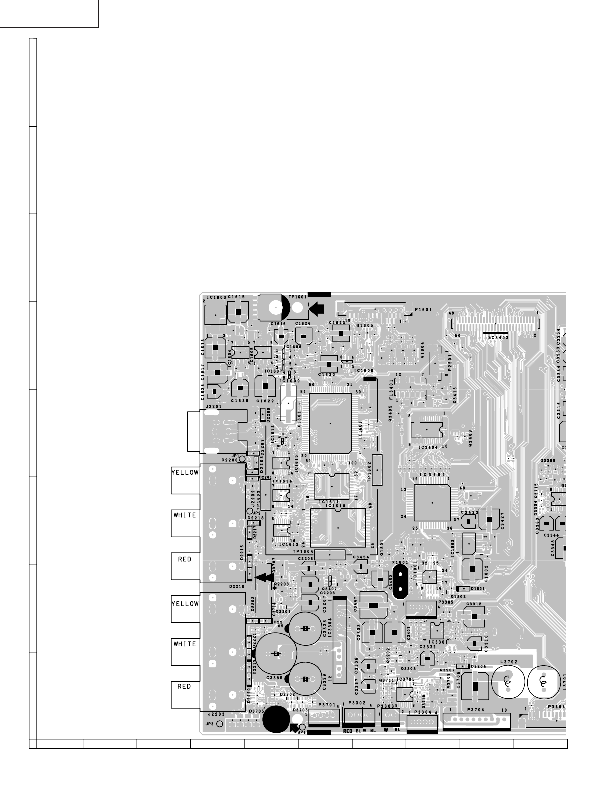
LC-15B5M
H
G
F
ANALOG Unit (Side-A)
E
D
C
B
A
87109654321
80
Page 81

LC-15B5M
81
1716 1918151413121110
Page 82

LC-15B5M
C3348
R
2
3
H
G
F
ANALOG Unit (Chip Parts Side-A)
TP1601
C1615
IC1603
E
D
C
C1613
C1617
C1634
C1637
J2201
J2202
B
J2203
A
R1614
C1611
FB1605
C1620
FB1606
C3715
C1614
IC1604
C1625
C1638
C1635
C3702
FB1601
D2206
D2201
R2229
R2222
R2225
R2216
D2203
C3701
D2207
D2218
D2216 D2215 R2211 R2213 D2217
D2220 D2219 D2222 D2221
C1618
R2223
R2205
C2201
R2254
R2214
R2253
C1621
C2204
Q3705
Q3706
FB1603
C1626
R2204
R2203
D2208
R2227
R2220
R3709
C3704
C2205
R2219
R2251
D2205
D3704
D3705
IC1605
C1629
C1622
D2209
C3714
FB1602
TP1603
R1647
FB1609
R1660
R1657
C3359
R3702
R1659
R3710
R1642 C1639
R1656
R3703
C1653
IC1608
IC1607
C1649
C1647 C1648
IC1612
R3732
D3707
Q2203
R1658
C1616
IC1614 IC1615
R1655
IC1613
Q2201
IC1609
X1601
FB1611
R1629
R1634
C1641
R1654
R2231 R2230
D3702
R1626 C1619
C1655 C1656
FB1608
C1654
D2204
Q1609
R2233 R2232
C1651
R1648
C1643
Q1803
R1815
C1646
R1637
C3338
C3339
C1652
D3703
C1624
C2208
C2206
C2207
Q1607
R1638
R3701
C1623
Q1602
R1624 R1615
R1616
L1601
R1627
C1627
R1636 R1635 R1630
C1630
C1650
R1651
IC1601
C1636
FB1607
IC1611
IC1610
TP1604
R3495
C3453
Q3414
R3485
R3466
Q3407
IC3304
C3358
C3340
P3701
Q1603
R3494
Q3412
IC1606
C3335 C3334
C1633
R1604
C1628
P3302
C3454
Q3411
R1603
R1631
C1645
C3450
R1605
FB1604
R1649
C1640 C1642
R3490
C3330
C3331
C3336
R3332
C3337
Q1605
R1646
R3497
C3447
P1601
R1622
C1644
R1645
R1643
R3487
C3333
R3325
R1602
R1811
R3486
R3324
C1632
R1652
TP1602
R3715
R3716
R3717
R3721
R3718
C3452
R3731
C1631
C3710
R1617
R1639
R3720
R3723
R3726
C3709
R3719
P3303
R1623
R1632
R1633
Q3711
Q1801
Q1608
R3322
R3323
Q3202
R1612
Q3405
C3407
R3724 R3484
R3461
R1618
R1640
C1810
R1813
R1625
R1628
R3459
R1808
R1803
C1806
X1801
R1613
R3474
R3460
Q1606
FL3401
R3468
R3455
C3328
C3329
Q3303
IC3701
R1619
R1641
R3456 R3457
C1805
R1620
R1621
R3450
C1803
C1804 R1804
R3306
C1807
R3725
R3728
R3727
Q1604
R3445 R3453
C1808
C3301
R3302
C3302
R3301
R3730
P3305
R3329 R3328
P3304
C3443
C1809
R3370
IC3404
R1806
D3706
C3441
R3440
IC1801
R3722
C3713
C3711
R3729
IC3401
R3449
C3332
Q3710
R1805
R1807
C3428
C3434 R3480
IC3301
P2201
C3426
C3305
Q3413
C3712 R3331 R3330
D3205
C3424
Q3709
Q3207
C3708
R1812
C3306
R1814
C3707
C3442
R3443
R3472
R3492
R3444
C3307
R3257
R3470
R3498
R1810
Q1802
C3304
R3303
C3303
C3425
R3714
R3369
R3256
R3247
R3477
C3422
R3304
D3204
D1801
R3248
R3255
R3442
R3408
R3471
R3305
Q3409
C3423
IC1802
L3401
R3308
C3312
R3469
C3310
C1802
R3307
P3704
R3366
C3706
C3311
C3421
R1802
C1801
SC3403
C3427
L3402
R1801
L3702
R3410
R3411
R3409
R3358
L3701
C3315
Q3715
D3304 C3314
Q3308
R3309
R3310
C3363
R3341 R3359 C3349
Q3307
P3404
C3313
R3343
C3361
R32
R322
IC3305
R
R3344
C3346
C3344
82
87109654321
Page 83

TP3423
R3407
C3405
C3404
C3403
C3401
R3402
CF3401
LC-15B5M
R3404
R1802
C1801
SC3403
C3427
L3402
R1801
R3410
R3411
R3358
C3315
D3304 C3314
Q3715
Q3308
R3309
R3310
C3363
R3341 R3359 C3349
Q3307
C3313
R3343
C3361
R3225
R3227
IC3305
C3344
R3206
C3346
C3254
C3253
C3244
C3216
R3344
C3348
R3346
R3342
C3362
C3232
R3226
C3230
C3202
R3357
C3345
C3347
R3345
C3251
R3340
C3222 C3218 C3228 C3234 C3243
C3209
D3208
R3339
C3343
L3201 FB3201
C3252
D3206
C3208
C3219
D3207
C3220
R3208
R3210
C2213
C3212
R3209
R3211
IC3201
X3201
R2247
R3375
C2212
R2235
C2210
C3308
C3213
L2201
C3309
C3210
C2211
C3365
R2237
R3373
R2236
D3201
R3374
C3364
R3205
D3202
R3250
C3245
R3249
FB3202
R3228
R3267
R3268
R3269
R3220
D3203
R2239
C3235
R3372
Q2204
C3236
C3274
R3201
IC3203 Q3201
R3224
R2240
Q2205
R3219
C3273
R3246
R2238
R3272
C3217
L3203
FB3203
P3201
C3272
IC3204
C3214
IC3206
R3222
C3237
C2214 L2203
C3211
C3271
IC3208
C3201
C3238
C3215
IC3207
R3223
Q2207
R3271
C3233
R3251
R3217
R3218
Q2208
R2243
R3252
R3270
R3234
R3204 R3207
C2209
R3203
C3270
C3437
R3235
IC3202
IC3209
C3231 C3268
C3432 R3465
C3433
C3436
R3261
R3236
C2218
R3458
R3451
C3431
C3229 C3267
R3263
R3239
R3464
C3263
C3221
C3430
R3448
R3447
R3452
IC3403
R3212
C3264
C3205
C3265
R3266
C3266
R3243
C3224
C3223
C3227
R3242
C3225
R3265
R3202
R3216
R3371
R3241
L2202
R3446
R3439
R3438
C3438
R2242
C3435
R2248
R2249
C3429
X3202
IC3205
C3206
X3203
C2203
R2208
C2202
Q2210
C3440
C3439
R2252
R2206
R2250
R2234
R2244
R2246
C2219
R2221
R2210
D2213
D2214
C2220
R2209
R2207
D2211
D2212
C2221
R2218
R2202
D2202
D2210
D2224
D2223
R2201
D2225
D2226
C2217
C2216
Q2206
R3406
C3406
R2245
R3405
R2241
IC3402
R3403
C2215
C3402
R3401
J2204 J2205
L3702
R3409
L3701
P3404
C3705
TU2201
Q3701
FH3703
D3701
Q3702
R3735
P3703
FH3701
P3702
R3734
F3702
J3701
TP3424
1716 1918151413121110
83
Page 84

LC-15B5M
H
G
F
E
D
C
B
INVERTER Unit (Side-A)
A
654321
84
Page 85

LC-15B5M
654321
A
B
C
D
E
F
G
H
FH6503 FH6504
R6517
R6506
C6508
R6518
Q6505
R6507
C6507
R6513
Q6503
Q6504
R6504
L6502
C6504
C6511
C6509
L6500
T6502
FH6502
FH6501
P6501
D6500
C6503
R6502
C6502
R6503
R6500
Q6502
R6501
Q6500
C6510
T6500
Q6501
P6500
P6502
INVERTER Unit (Chip Parts Side-A)
85
Page 86

LC-15B5M
Ref. No. Part No. ★ Description Code Ref. No. Part No. ★ Description Code
PARTS LIST
PARTS REPLACEMENT
Replacement parts which have these special safety characteristics
identified in this manual; electrical components having such features
are identified by
and Schematic Diagrams. The use of a substitute replacement part
which does no have the same safety characteristic as the factory
recommended replacement parts shown in this service manual may
create shock, fire or other hazards.
"HOW TO ORDER REPLACEMENT P ARTS"
To have your order filled promptly and correctly, please furnish the
following informations.
1. MODEL NUMBER 2. R E F. NO.
3. P AR T N O. 4. DESCRIPTION
Ref. No. Part No. ★ Description Code
PRINTED WIRING BOARD ASSEMBLIES
å and shaded areas in the Replacement Parts Lists
★ MARK: SPARE PARTS-DELIVERY SECTION
(NOT REPLACEMENT ITEM)
LC-15B5M
DUNTKC316FE08 – MAIN Unit —
DUNTKC351FE08 – INVERTER Unit —
DUNTKC352DE05 – ANALOG Unit —
DUNTKC353DE05 – OPERATION Unit —
DUNTKC354DE05 – R/C,LED Unit —
DUNTKC355DE05 – CARD LED Unit —
LC-15B5M(X)
DUNTKC316FE08 – MAIN Unit —
DUNTKC351FE08 – INVERTER Unit —
DUNTKC352DE08 – ANALOG Unit —
DUNTKC353DE08 – OPERATION Unit —
DUNTKC354DE08 – R/C,LED Unit —
DUNTKC355DE08 – CARD LED Unit —
DUNTKC316FE08
MAIN UNIT
INTEGRATED CIRCUITS
IC701 RH-iXA828WJZZY J BD9300FV-FE2 AH
IC702 RH-iXA828WJZZY J BD9300FV-FE2 AH
IC703 RH-iXA828WJZZY J BD9300FV-FE2 AH
IC704 RH-iXA828WJZZY J BD9300FV-FE2 AH
IC1101 VHiBD8120FP-1Y J BD8120FP AX
IC1201 RH-iXA595WJZZQ J LR38853 BC
IC1202 VHiiCS570B+-1Y J ICS570BT AQ
IC1204 VHiNC7SV04+-1Y J NC7SV04P5X AD
IC1701 VHiNJM2147M-1Y J NJM2147M-TE1 AF
IC1702 VHiPQ1R34++-1Y J PQ1R34 AE
IC2001 RH-iXA642WJN1Q J M306V7FHFP BM
IC2002 VHiPQ1L333M-1Y J PQ1L333M2SP AD
IC2003 VHiBD4729G+-1Y J BD4729G-TR AD
IC2004 VHiPQ20VZ11-1Y J PQ20VZ11 AG
IC2005 VHiBR24C32F-1Y J BR24C32F-E2 AH
IC2006 VHiTC4W66F/-1Y J TC4W66F AE
IC5001 RH-iXA805WJZZQ J TMS320DM270GHK BG
IC5003 RH-iXA897WJN1Q J LH28F320BFHE-P AW
IC5004 VHiPQ070XZ1-1Y J PQ070XZ01ZP AF
IC5006 RH-iXA312WJN1Q J MT48LC2M32B2TG AX
IC5201 RH-iXA420WJZZQ J TMS320DA150GGU BE
IC5401 VHiLV244AT+-1Y J SN74LV244APWR AF
IC5402 VHiLV244AT+-1Y J SN74LV244APWR AF
IC5403 VHiLV244AT+-1Y J SN74LV244APWR AF
IC5404 VHiLV244AT+-1Y J SN74LV244APWR AF
IC5405 VHiLV245AT+-1Y J SN74LV245APWR AF
IC5406 VHiLV245AT+-1Y J SN74LV245APWR AF
IC5407 VHiNC7WZ125-1Y J NC7WZ125 AD
IC5408 VHiTC7W08U/-1Y J TC7W08FU AD
IC5409 VHiPQ20WZ11-1Y J PQ20WZ1U AF
IC8501 RH-iXA801WJZZQ J FLI2310-LF-BD BF
IC8502 RH-iXA312WJN1Q J MT48LC2M32B2TG AX
IC8503 VHiPQ070XZ1-1Y J PQ070XZ01ZP AF
IC8504 VHiTC7W74U/-1Y J TC7W74FU AD
IC8601 VHiNC7WZ125-1Y J NC7WZ125 AD
IC8602 VHiTAC541FT-1Y J TC74AC541FT AL
IC8603 VHiTAC541FT-1Y J TC74AC541FT AL
IC8606 VHiLCX244MT-1Y J 74LCx244 AE
IC8701 VHiAD9883A1-1Q J AD9883AKST-110 BD
IC8801 VHiVPC3230D1EQ J VPC3230D-QA-B3 BD
IC8803 VHiBA7046F/-1Y J BA7046F AF
LCD PANEL
NOTE: THE PARTS HERE SHOWN ARE SUPPLIED AS AN
ASSEMBLY BUT NOT INDEPENDENTLY.
RLCDTA024WJZZ J 15" LCD Panel Unit CT
Q704 VSDTC144EKA-1Y J DTC144EKA AB
TRANSISTORS
Q705 VSUML2N++++-1Y J UML2N AC
Q706 VSUML2N++++-1Y J UML2N AC
Q707 VSUML2N++++-1Y J UML2N AC
Q709 VSUML1N++++-1Y J UML1N AC
Q711 VSUML2N++++-1Y J UML2N AC
Q712 VSRTQ035P02-1Y J RTQ035P02 AD
Q713 VSRTQ035P02-1Y J RTQ035P02 AD
Q714 VSRTQ035P02-1Y J RTQ035P02 AD
Q716 VSRHP020N06-1Y J RHP020N06 AD
Q1101 VSFMMT718//-1Y J FMMT718 AE
Q1104 VSDTC144EE/-1Y J DTC144EE AA
Q1105 VS2SC5566++-1Y J 2SC5566 AD
Q1106 VS2SA2013++-1Y J 2SA2013 AD
Q1701 VS2SA1037KQ-1Y J 2SA1037KQ AA
Q1702 VSDTC144EE/-1Y J DTC144EE AA
Q1703 VS2SA1036K/-1Y J 2SA1036K AC
Q1705 VSDTC144EE/-1Y J DTC144EE AA
Q2002 VS2SA1037KQ-1Y J 2SA1037KQ AA
Q2003 VSDTC144EE/-1Y J DTC144EE AA
Q2004 VS2SC3928AR-1Y J 2SC3928AR AB
Q2005 VSDTC144EE/-1Y J DTC144EE AA
Q2006 VSDTC114EE/-1Y J DTC114EE AB
Q2007 VSUPA606T//-1Y J UPA606T AD
Q2008 VSDTC144EE/-1Y J DTC144EE AA
Q2010 VSDTC114EE/-1Y J DTC114EE AB
Q2012 VSUMG9N++++-1Y J UMG9N AB
86
Page 87

LC-15B5M
Ref. No. Part No. ★ Description Code Ref. No. Part No. ★ Description Code
DUNTKC316FE08
MAIN UNIT (Continued)
Q2013 VSUMG9N++++-1Y J UMG9N AB
Q2014 VS2SC3928AR-1Y J 2SC3928AR AB
Q2015 VSDTC144EE/-1Y J DTC144EE AA
Q2016 VSFMMT718//-1Y J FMMT718 AE
Q5001 VS2SA1362GR-1Y J 2SA1362GR AC
Q5002 VSDTC144EE/-1Y J DTC144EE AA
Q5406 VSDTC144EE/-1Y J DTC144EE AA
Q5407 VSDTC144EE/-1Y J DTC144EE AA
Q8601 VSDTC144EE/-1Y J DTC144EE AA
Q8602 VSFMMT718//-1Y J FMMT718 AE
Q8603 VSDTC144EE/-1Y J DTC144EE AA
Q8802 VS2SC5384C/-1Y J 2SC5384C AB
DIODES
D701 VHDRB051L40-1Y J Diode AD
D702 VHDRB051L40-1Y J Diode AD
D703 VHDRB051L40-1Y J Diode AD
D705 VHDRF071M2S-1Y J Diode AD
D706 VHDRB160M40-1Y J Diode AC
D707 VHD1SS355//-1Y J Diode AB
D708 VHDRB160M40-1Y J Diode AC
D709 VHDRB160M40-1Y J Diode AC
D711 VHDSFPB56//2EY J Diode AC
D720 VHDDAN222//-1Y J Diode AA
D1102 VHDDAN222//-1Y J Diode AA
D1103 VHD1SS250//1EY J Diode AB
D1104 VHD1SS250//1EY J Diode AB
D1105 VHD1SS250//1EY J Diode AB
D1106 VHD1SS250//1EY J Diode AB
D1107 VHD1SS250//1EY J Diode AB
D1701 VHDDAN222//-1Y J Diode AA
D1702 RH-EX1224CEZZY J Zener Diode AB
D1703 VHDDAN222//-1Y J Diode AA
D1704 RH-EX1224CEZZY J Zener Diode AB
D1705 VHDDAN222//-1Y J Diode AA
D1706 VHDDAN222//-1Y J Diode AA
D1707 VHD1SS250//1EY J Diode AB
D1708 VHDRB481K++-1Y J Diode AD
D2001 VHDDAN202K/-1Y J Diode AB
D2002 RH-EX1396CEZZY J Zener Diode AB
D2003 VHDRB491D++-1Y J Diode AD
D2005 VHDDAN222//-1Y J Diode AA
D5001 RH-FXA008WJZZY J Gp1S092Hcpif AD
D8501 VHDDAN202K/-1Y J Diode AB
P ACKAGED CIRCUITS
X2001 RCRSC0032TAZZY J Crystal AG
X5001 RCRUAA008WJZZY J Crystal AM
X5201 RCRSC0186TAZZY J Crystal AK
X8501 RCRSC0193TAZZY J Crystal AH
X8801 RCRSC0012CEZZY J Crystal AH
FIL TERS AND COILS
FL1201 RFiLN0097GEZZY J Filter AF
FL2001 RFiLZA003WJPZY J Filter AD
L701 RCiLPA154WJZZY J Coil AE
L703 RCiLPA155WJZZY J Coil AE
L704 RCiLPA154WJZZY J Coil AE
L1701 RCiLPA143WJZZY J Coil AD
L1702 VPCNN470J5R4NY J Peaking 47µH AB
L8501 VPCNN5R6J1R2NY J Peaking 5.6µH AB
L8502 VPCNN5R6J1R2NY J Peaking 5.6µH AB
L8801 VP-9N3R3KR46NY J Peaking 3.3µH AC
L8802 VP-9N3R3KR46NY J Peaking 3.3µH AC
L8803 VP-9N3R3KR46NY J Peaking 3.3µH AC
L8804 RCiLPA143WJZZY J Coil AD
L8805 RCiLPA143WJZZY J Coil AD
L8806 VP-9N3R3KR46NY J Peaking 3.3µH AC
L8807 VP-9N3R3KR46NY J Peaking 3.3µH AC
L8808 VP-9N3R3KR46NY J Peaking 3.3µH AC
T701 RTRNWA120WJZZY J Transformer AG
TRANSFORMER
CAP ACIT ORS
C701 VCKYCY1EF104ZY J 0.1 25V Ceramic AA
C702 VCKYCY1EB333KY J 0.033 25V Ceramic AA
C703 VCKYCY1EB333KY J 0.033 25V Ceramic AA
C705 VCKYCY1EB333KY J 0.033 25V Ceramic AA
C706 VCKYCY1EB333KY J 0.033 25V Ceramic AA
C710 VCCCCY1HH102JY J 1000p 50V Ceramic AB
C711 VCCCCY1HH102JY J 1000p 50V Ceramic AB
C713 VCCCCY1HH331JY J 330p 50V Ceramic AA
C714 VCKYCY1HB332KY J 3300p 50V Ceramic AA
C716 VCCCCY1HH330JY J 33p 50V Ceramic AA
C721 VCCCCY1HH330JY J 33p 50V Ceramic AA
C722 VCCCCY1HH101JY J 100p 50V Ceramic AA
C723 VCCCCY1HH101JY J 100p 50V Ceramic AA
C725 VCCCCY1HH101JY J 100p 50V Ceramic AA
C726 VCCCCY1HH181JY J 180p 50V Ceramic AA
C727 RC-KZA113WJZZY J 4.7 16V Ceramic AB
C728 RC-KZA113WJZZY J 4.7 16V Ceramic AB
C729 RC-KZA113WJZZY J 4.7 16V Ceramic AB
C730 RC-KZA113WJZZY J 4.7 16V Ceramic AB
C732 RC-KZA109WJZZY J 10 16V Ceramic AC
C733 RC-KZA109WJZZY J 10 16V Ceramic AC
C735 RC-KZA109WJZZY J 10 16V Ceramic AC
C736 VCCCCY1HH102JY J 1000p 50V Ceramic AB
C738 VCCCCY1HH102JY J 1000p 50V Ceramic AB
C739 VCCCCY1HH102JY J 1000p 50V Ceramic AB
C740 VCCCCY1HH102JY J 1000p 50V Ceramic AB
C741 RC-KZA108WJZZY J 10 10V Ceramic AC
C742 RC-KZA101WJZZY J 10 6.3V Ceramic AC
C743 RC-KZA108WJZZY J 10 10V Ceramic AC
C744 RC-KZA101WJZZY J 10 6.3V Ceramic AC
C745 RC-KZA108WJZZY J 10 10V Ceramic AC
C747 RC-KZA109WJZZY J 10 16V Ceramic AC
C750 RC-KZ0072TAZZY J 1 25V Ceramic AC
C751 RC-KZ0072TAZZY J 1 25V Ceramic AC
C753 RC-KZA101WJZZY J 10 6.3V Ceramic AC
C754 RC-KZA101WJZZY J 10 6.3V Ceramic AC
C756 RC-KZA109WJZZY J 10 16V Ceramic AC
C758 RC-KZA109WJZZY J 10 16V Ceramic AC
C759 RC-KZA041WJZZY J 10 10V Ceramic AC
C760 RC-KZA041WJZZY J 10 10V Ceramic AC
C761 RC-KZA109WJZZY J 10 16V Ceramic AC
C766 VCKYCY1HB562KY J 5600p 50V Ceramic AA
C1101 RC-KZA041WJZZY J 10 10V Ceramic AC
C1102 VCKYCY1EF104ZY J 0.1 25V Ceramic AA
C1104 RC-KZA101WJZZY J 10 6.3V Ceramic AC
C1106 RC-KZA041WJZZY J 10 10V Ceramic AC
C1107 VCCCCY1HH560JY J 56p 50V Ceramic AB
C1109 VCKYCY1EF104ZY J 0.1 25V Ceramic AA
C1114 VCKYTV1CB105KY J 1 16V Ceramic AC
C1115 VCKYTV1CB105KY J 1 16V Ceramic AC
C1116 VCKYCY1EF104ZY J 0.1 25V Ceramic AA
C1117 RC-KZA041WJZZY J 10 10V Ceramic AC
C1119 VCAAPD0JJ476MY J 47 6.3V Electrolytic AE
C1122 VCKYTV1EB104KY J 0.1 25V Ceramic AB
C1204 VCKYCY1HB103KY J 0.01 50V Ceramic AA
C1205 VCKYTV1CF105ZY J 1 16V Ceramic AB
C1207 VCKYCY1EF104ZY J 0.1 25V Ceramic AA
C1211 RC-KZA101WJZZY J 10 6.3V Ceramic AC
C1212 VCKYCY1EF104ZY J 0.1 25V Ceramic AA
C1213 VCKYCY1EF104ZY J 0.1 25V Ceramic AA
C1215 VCKYCY1EF104ZY J 0.1 25V Ceramic AA
C1216 VCKYCY1EF104ZY J 0.1 25V Ceramic AA
C1217 VCKYCY1EF104ZY J 0.1 25V Ceramic AA
C1218 VCKYCY1EF104ZY J 0.1 25V Ceramic AA
C1219 VCKYCY1EF104ZY J 0.1 25V Ceramic AA
C1224 VCKYCY1EF104ZY J 0.1 25V Ceramic AA
C1225 VCKYCY1EF104ZY J 0.1 25V Ceramic AA
C1228 VCKYCY1EF104ZY J 0.1 25V Ceramic AA
C1229 VCKYCY1EF104ZY J 0.1 25V Ceramic AA
C1230 VCKYCY1EF104ZY J 0.1 25V Ceramic AA
C1701 VCKYCY1EF104ZY J 0.1 25V Ceramic AA
87
Page 88

LC-15B5M
Ref. No. Part No. ★ Description Code Ref. No. Part No. ★ Description Code
DUNTKC316FE08
MAIN UNIT (Continued)
C1702 VCKYCY1EF104ZY J 0.1 25V Ceramic AA
C1703 VCKYCY1EF104ZY J 0.1 25V Ceramic AA
C1704 VCEASY1CN337MY J 330 16V Electrolytic AD
C1705 VCKYTV1CB105KY J 1 16V Ceramic AC
C1706 VCKYTV1CB105KY J 1 16V Ceramic AC
C1707 RC-KZA101WJZZY J 10 6.3V Ceramic AC
C1708 VCKYTV1CB105KY J 1 16V Ceramic AC
C1709 VCEASX1HN106MY J 10 50V Electrolytic AC
C1710 RC-KZA101WJZZY J 10 6.3V Ceramic AC
C1711 RC-KZA041WJZZY J 10 10V Ceramic AC
C1712 VCEASY0JN227MY J 220 6.3V Electrolytic AC
C1713 RC-KZA101WJZZY J 10 6.3V Ceramic AC
C1714 VCEASX1HN475MY J 4.7 50V Electrolytic AC
C1715 VCKYCY1HF104ZY J 0.1 50V Ceramic AA
C2001 VCKYTV1CF105ZY J 1 16V Ceramic AB
C2002 VCKYCY1EF104ZY J 0.1 25V Ceramic AA
C2003 VCKYCY1EF104ZY J 0.1 25V Ceramic AA
C2004 RC-KZA101WJZZY J 10 6.3V Ceramic AC
C2005 RC-KZA101WJZZY J 10 6.3V Ceramic AC
C2007 VCKYCY1EF104ZY J 0.1 25V Ceramic AA
C2009 VCKYCY1HB102KY J 1000p 50V Ceramic AA
C2010 VCCCCY1HH221JY J 220p 50V Ceramic AA
C2011 VCKYTV1CF684ZY J 0.68 16V Ceramic AB
C2012 VCKYCY1AB105KY J 1 10V Ceramic AB
C2013 VCCCCY1HH5R0CY J 5p 50V Ceramic AA
C2014 VCKYCY1EF104ZY J 0.1 25V Ceramic AA
C2015 VCCCCY1HH180JY J 18p 50V Ceramic AA
C2016 VCKYCY1EF104ZY J 0.1 25V Ceramic AA
C2017 VCKYCY1EF104ZY J 0.1 25V Ceramic AA
C2018 VCKYCY1EF104ZY J 0.1 25V Ceramic AA
C2019 VCKYCY1EF104ZY J 0.1 25V Ceramic AA
C2020 RC-KZA101WJZZY J 10 6.3V Ceramic AC
C2022 VCKYCY1HB222KY J 2200p 50V Ceramic AA
C2023 VCKYCY1HB222KY J 2200p 50V Ceramic AA
C2024 VCKYCY1EF104ZY J 0.1 25V Ceramic AA
C2027 VCEASX0JN476MY J 47 6.3V Electrolytic AC
C5001 VCKYCY1HF103ZY J 0.01 50V Ceramic AA
C5002 VCKYCY1HF103ZY J 0.01 50V Ceramic AA
C5003 VCKYCY1HF103ZY J 0.01 50V Ceramic AA
C5004 VCKYCY1HF103ZY J 0.01 50V Ceramic AA
C5005 VCKYCY1HF103ZY J 0.01 50V Ceramic AA
C5006 VCKYCY1HF103ZY J 0.01 50V Ceramic AA
C5007 VCKYCY1HF103ZY J 0.01 50V Ceramic AA
C5008 VCKYCY1HF103ZY J 0.01 50V Ceramic AA
C5009 VCKYCY1HF103ZY J 0.01 50V Ceramic AA
C5010 VCKYCY1HF103ZY J 0.01 50V Ceramic AA
C5011 RC-KZA041WJZZY J 10 10V Ceramic AC
C5012 VCKYCY1HF103ZY J 0.01 50V Ceramic AA
C5013 VCKYCY1HF103ZY J 0.01 50V Ceramic AA
C5015 VCKYCY1HF103ZY J 0.01 50V Ceramic AA
C5016 VCKYCY1HF103ZY J 0.01 50V Ceramic AA
C5017 VCKYCY1HF103ZY J 0.01 50V Ceramic AA
C5018 VCKYCY1HF103ZY J 0.01 50V Ceramic AA
C5019 VCKYCY1HF103ZY J 0.01 50V Ceramic AA
C5020 VCKYCY1EF104ZY J 0.1 25V Ceramic AA
C5021 VCKYCY1EF104ZY J 0.1 25V Ceramic AA
C5022 VCKYCY1EF104ZY J 0.1 25V Ceramic AA
C5023 VCKYCY1EF104ZY J 0.1 25V Ceramic AA
C5024 VCKYCY1EF104ZY J 0.1 25V Ceramic AA
C5025 VCKYCY1EF104ZY J 0.1 25V Ceramic AA
C5026 VCKYCY1EF104ZY J 0.1 25V Ceramic AA
C5027 VCKYCY1EF104ZY J 0.1 25V Ceramic AA
C5028 VCKYCY1EF104ZY J 0.1 25V Ceramic AA
C5029 VCKYCY1EF104ZY J 0.1 25V Ceramic AA
C5030 RC-KZA041WJZZY J 10 10V Ceramic AC
C5034 VCCCCY1HH100DY J 10p 50V Ceramic AA
C5201 VCKYCY1EF104ZY J 0.1 25V Ceramic AA
C5202 VCKYCY1EF104ZY J 0.1 25V Ceramic AA
C5203 VCKYCY1EF104ZY J 0.1 25V Ceramic AA
C5204 VCKYCY1EF104ZY J 0.1 25V Ceramic AA
C5205 VCKYCY1EF104ZY J 0.1 25V Ceramic AA
C5206 VCKYCY1EF104ZY J 0.1 25V Ceramic AA
C5207 VCKYCY1EF104ZY J 0.1 25V Ceramic AA
C5208 VCKYCY1EF104ZY J 0.1 25V Ceramic AA
C5209 VCCCCY1HH6R0DY J 6p 50V Ceramic AA
C5210 VCCCCY1HH6R0DY J 6p 50V Ceramic AA
C5401 VCKYCY1EF104ZY J 0.1 25V Ceramic AA
C5402 VCKYCY1EF104ZY J 0.1 25V Ceramic AA
C5403 VCKYCY1EF104ZY J 0.1 25V Ceramic AA
C5404 VCKYCY1EF104ZY J 0.1 25V Ceramic AA
C5405 VCKYCY1EF104ZY J 0.1 25V Ceramic AA
C5406 VCKYCY1EF104ZY J 0.1 25V Ceramic AA
C5407 VCKYCY1EF104ZY J 0.1 25V Ceramic AA
C5408 RC-KZA041WJZZY J 10 10V Ceramic AC
C5409 RC-KZA041WJZZY J 10 10V Ceramic AC
C5410 RC-KZA041WJZZY J 10 10V Ceramic AC
C5411 RC-KZA041WJZZY J 10 10V Ceramic AC
C5412 RC-KZA108WJZZY J 10 10V Ceramic AC
C5413 RC-KZA108WJZZY J 10 10V Ceramic AC
C8501 VCKYCY1EF104ZY J 0.1 25V Ceramic AA
C8502 VCKYCY1EF104ZY J 0.1 25V Ceramic AA
C8503 VCKYCY1EF104ZY J 0.1 25V Ceramic AA
C8504 VCKYCY1EF104ZY J 0.1 25V Ceramic AA
C8505 VCKYCY1EF104ZY J 0.1 25V Ceramic AA
C8506 VCKYCY1EF104ZY J 0.1 25V Ceramic AA
C8507 VCKYCY1EF104ZY J 0.1 25V Ceramic AA
C8508 VCCCCY1HH270JY J 27p 50V Ceramic AA
C8509 VCKYCY1EF104ZY J 0.1 25V Ceramic AA
C8510 VCKYCY1EF104ZY J 0.1 25V Ceramic AA
C8511 VCCCCY1HH270JY J 27p 50V Ceramic AA
C8512 VCKYTV1CF105ZY J 1 16V Ceramic AB
C8513 VCKYCY1HF103ZY J 0.01 50V Ceramic AA
C8514 VCKYCY1EF104ZY J 0.1 25V Ceramic AA
C8515 VCKYCY1HF103ZY J 0.01 50V Ceramic AA
C8516 VCKYTV1CF105ZY J 1 16V Ceramic AB
C8517 RC-KZA041WJZZY J 10 10V Ceramic AC
C8518 VCKYCY1EF104ZY J 0.1 25V Ceramic AA
C8519 VCKYCY1EF104ZY J 0.1 25V Ceramic AA
C8520 VCKYCY1EF104ZY J 0.1 25V Ceramic AA
C8521 VCKYCY1EF104ZY J 0.1 25V Ceramic AA
C8522 VCKYCY1EF104ZY J 0.1 25V Ceramic AA
C8523 VCKYCY1EF104ZY J 0.1 25V Ceramic AA
C8524 VCKYCY1EF104ZY J 0.1 25V Ceramic AA
C8525 RC-KZA101WJZZY J 10 6.3V Ceramic AC
C8526 VCKYCY1EF104ZY J 0.1 25V Ceramic AA
C8527 VCKYCY1EF104ZY J 0.1 25V Ceramic AA
C8528 VCKYCY1EF104ZY J 0.1 25V Ceramic AA
C8529 VCKYCY1EF104ZY J 0.1 25V Ceramic AA
C8530 VCKYTV1CF105ZY J 1 16V Ceramic AB
C8531 VCKYCY1EF104ZY J 0.1 25V Ceramic AA
C8532 VCKYCY1EF104ZY J 0.1 25V Ceramic AA
C8533 VCKYCY1EF104ZY J 0.1 25V Ceramic AA
C8534 RC-KZA101WJZZY J 10 6.3V Ceramic AC
C8535 RC-KZ0117TAZZY J 4.7 6.3V Ceramic AD
C8536 RC-KZ0117TAZZY J 4.7 6.3V Ceramic AD
C8537 RC-KZA041WJZZY J 10 10V Ceramic AC
C8538 RC-KZA101WJZZY J 10 6.3V Ceramic AC
C8539 RC-KZA101WJZZY J 10 6.3V Ceramic AC
C8540 RC-KZA101WJZZY J 10 6.3V Ceramic AC
C8541 RC-KZA101WJZZY J 10 6.3V Ceramic AC
C8542 VCEASX0JN107MY J 100 6.3V Electrolytic AC
C8601 VCKYCY1EF104ZY J 0.1 25V Ceramic AA
C8602 RC-KZA101WJZZY J 10 6.3V Ceramic AC
C8603 VCKYCY1EF104ZY J 0.1 25V Ceramic AA
C8604 VCKYCY1EF104ZY J 0.1 25V Ceramic AA
C8605 VCKYCY1EF104ZY J 0.1 25V Ceramic AA
C8606 VCKYCY1EF104ZY J 0.1 25V Ceramic AA
C8607 VCKYCY1EF104ZY J 0.1 25V Ceramic AA
C8701 VCKYCY1EF104ZY J 0.1 25V Ceramic AA
C8702 RC-KZA070WJZZY J 22 6.3V Ceramic AD
C8703 VCKYCY1EF104ZY J 0.1 25V Ceramic AA
C8704 RC-KZA101WJZZY J 10 6.3V Ceramic AC
C8705 VCKYCY1EF104ZY J 0.1 25V Ceramic AA
C8706 VCKYCY1EF104ZY J 0.1 25V Ceramic AA
C8707 VCKYCY1CB823KY J 0.082 16V Ceramic AH
C8708 VCKYCY1EF104ZY J 0.1 25V Ceramic AA
88
Page 89

LC-15B5M
Ref. No. Part No. ★ Description Code Ref. No. Part No. ★ Description Code
DUNTKC316FE08
MAIN UNIT (Continued)
C8709 VCKYCY1HB822KY J 8200p 50V Ceramic AB
C8710 RC-KZA101WJZZY J 10 6.3V Ceramic AC
C8711 VCKYCY1EF104ZY J 0.1 25V Ceramic AA
C8712 VCKYCY1EF104ZY J 0.1 25V Ceramic AA
C8713 VCKYCY1EF104ZY J 0.1 25V Ceramic AA
C8714 VCKYCY1EF104ZY J 0.1 25V Ceramic AA
C8715 RC-KZA070WJZZY J 22 6.3V Ceramic AD
C8716 VCKYCY1HB102KY J 1000p 50V Ceramic AA
C8717 VCKYCY1CB473KY J 0.047 16V Ceramic AA
C8718 VCKYCY1CB473KY J 0.047 16V Ceramic AA
C8719 VCKYCY1CB473KY J 0.047 16V Ceramic AA
C8720 VCKYCY1EF104ZY J 0.1 25V Ceramic AA
C8801 VCKYTV1AB105KY J 1 10V Ceramic AC
C8802 VCKYCY1HB222KY J 2200p 50V Ceramic AA
C8803 VCCCCY1HH101JY J 100p 50V Ceramic AA
C8806 RC-KZA041WJZZY J 10 10V Ceramic AC
C8807 VCKYTV1AB105KY J 1 10V Ceramic AC
C8808 RC-KZA101WJZZY J 10 6.3V Ceramic AC
C8809 VCKYTV1HB103KY J 0.01 50V Ceramic AA
C8810 VCKYTV1HB103KY J 0.01 50V Ceramic AA
C8811 VCKYTV1HB103KY J 0.01 50V Ceramic AA
C8812 VCKYCY1EF104ZY J 0.1 25V Ceramic AA
C8813 VCKYCY1HB102KY J 1000p 50V Ceramic AA
C8814 VCKYCY1AB684KY J 0.68 10V Ceramic AB
C8815 VCKYCY1AB224KY J 0.22 10V Ceramic AB
C8816 RC-KZA101WJZZY J 10 6.3V Ceramic AC
C8817 VCKYCY1AB684KY J 0.68 10V Ceramic AB
C8819 RC-KZA101WJZZY J 10 6.3V Ceramic AC
C8820 VCEASX0JN107MY J 100 6.3V Electrolytic AC
C8821 VCKYCY1EF104ZY J 0.1 25V Ceramic AA
C8822 RC-KZ1025CEZZY J 1 10V Ceramic AB
C8823 RC-KZ1025CEZZY J 1 10V Ceramic AB
C8824 VCKYCY1EF104ZY J 0.1 25V Ceramic AA
C8825 VCEASX0JN107MY J 100 6.3V Electrolytic AC
C8826 VCKYCY1HB331KY J 330p 50V Ceramic AA
C8827 VCKYCY1HB331KY J 330p 50V Ceramic AA
C8828 RC-KZA041WJZZY J 10 10V Ceramic AC
C8829 VCKYCY1HB331KY J 330p 50V Ceramic AA
C8830 VCKYCY1AB224KY J 0.22 10V Ceramic AB
C8831 VCKYCY1EF104ZY J 0.1 25V Ceramic AA
C8832 VCKYCY1AB224KY J 0.22 10V Ceramic AB
C8833 VCCCCY1HH7R0DY J 7p 50V Ceramic AA
C8834 VCKYCY1AB224KY J 0.22 10V Ceramic AB
C8836 VCKYCY1EF104ZY J 0.1 25V Ceramic AA
C8838 VCCCCY1HH7R0DY J 7p 50V Ceramic AA
C8840 RC-KZ0117TAZZY J 4.7 6.3V Ceramic AD
C8841 RC-KZ1025CEZZY J 1 10V Ceramic AB
C8842 RC-KZ1025CEZZY J 1 10V Ceramic AB
C8844 RC-KZ0071TAZZY J 2.2 6.3V Ceramic AD
C8845 RC-KZA101WJZZY J 10 6.3V Ceramic AC
C8846 VCKYCY1EF104ZY J 0.1 25V Ceramic AA
C8847 VCKYCY1EF104ZY J 0.1 25V Ceramic AA
C8848 VCKYTV1HB103KY J 0.01 50V Ceramic AA
C8849 VCKYCY1AB224KY J 0.22 10V Ceramic AB
C8850 VCKYCY1AB224KY J 0.22 10V Ceramic AB
C8851 VCKYCY1AB224KY J 0.22 10V Ceramic AB
C8854 VCKYCY1HB681KY J 680p 50V Ceramic AA
C8855 VCKYCY1HB681KY J 680p 50V Ceramic AA
C8857 VCKYCY1HB681KY J 680p 50V Ceramic AA
RESISTORS
R705 VRS-CY1JF103JY J 10k 1/16W Metal Oxide AA
R706 VRS-CY1JF103JY J 10k 1/16W Metal Oxide AA
R707 VRS-CY1JF333JY J 33k 1/16W Metal Oxide AA
R708 VRS-CY1JF333JY J 33k 1/16W Metal Oxide AA
R710 VRS-CY1JF333JY J 33k 1/16W Metal Oxide AA
R711 VRS-CY1JF104DY J 100k 1/16W Metal Oxide AA
R712 VRS-CY1JF104DY J 100k 1/16W Metal Oxide AA
R713 VRS-CY1JF104DY J 100k 1/16W Metal Oxide AA
R714 VRS-CY1JF104DY J 100k 1/16W Metal Oxide AA
R715 VRS-CY1JF104DY J 100k 1/16W Metal Oxide AA
R716 VRS-CY1JF104DY J 100k 1/16W Metal Oxide AA
R719 VRS-CY1JF104DY J 100k 1/16W Metal Oxide AA
R720 VRS-CY1JF104DY J 100k 1/16W Metal Oxide AA
R721 VRS-CY1JF333JY J 33k 1/16W Metal Oxide AA
R722 VRS-CY1JF223JY J 22k 1/16W Metal Oxide AA
R723 VRS-CY1JF223JY J 22k 1/16W Metal Oxide AA
R725 VRS-CY1JF223JY J 22k 1/16W Metal Oxide AA
R726 VRS-CY1JF223JY J 22k 1/16W Metal Oxide AA
R727 VRS-CY1JF223JY J 22k 1/16W Metal Oxide AA
R728 VRS-CY1JF303FY J 30k 1/16W Metal Oxide AA
R729 VRS-CY1JF223JY J 22k 1/16W Metal Oxide AA
R731 VRS-CY1JF104JY J 100k 1/16W Metal Oxide AA
R732 VRS-CY1JF104JY J 100k 1/16W Metal Oxide AA
R733 VRS-CY1JF333FY J 33k 1/16W Metal Oxide AA
R734 VRS-CY1JF473FY J 47k 1/16W Metal Oxide AA
R735 VRS-CY1JF203FY J 20k 1/16W Metal Oxide AA
R736 VRS-CY1JF203FY J 20k 1/16W Metal Oxide AA
R738 VRS-CY1JF104FY J 100k 1/16W Metal Oxide AA
R739 VRS-CY1JF154FY J 150k 1/16W Metal Oxide AA
R740 VRS-CY1JF000JY J 0 1/16W Metal Oxide AA
R741 VRS-CY1JF333FY J 33k 1/16W Metal Oxide AA
R742 VRS-CY1JF000JY J 0 1/16W Metal Oxide AA
R743 VRS-CY1JF562JY J 5.6k 1/16W Metal Oxide AA
R744 VRS-CY1JF473FY J 47k 1/16W Metal Oxide AA
R745 VRS-CY1JF000JY J 0 1/16W Metal Oxide AA
R749 VRS-CY1JF000JY J 0 1/16W Metal Oxide AA
R758 VRS-CY1JF103JY J 10k 1/16W Metal Oxide AA
R759 VRS-CY1JF103JY J 10k 1/16W Metal Oxide AA
R760 VRS-CY1JF103JY J 10k 1/16W Metal Oxide AA
R761 VRS-CY1JF103JY J 10k 1/16W Metal Oxide AA
R763 VRS-CY1JF101JY J 100 1/16W Metal Oxide AA
R764 VRS-CY1JF331JY J 330 1/16W Metal Oxide AA
R765 VRS-CY1JF511JY J 510 1/16W Metal Oxide AA
R769 VRS-CY1JF511JY J 510 1/16W Metal Oxide AA
R770 VRS-CY1JF511JY J 510 1/16W Metal Oxide AA
R771 VRS-CY1JF511JY J 510 1/16W Metal Oxide AA
R772 VRS-CY1JF511JY J 510 1/16W Metal Oxide AA
R773 VRS-CY1JF511JY J 510 1/16W Metal Oxide AA
R774 VRS-CY1JF511JY J 510 1/16W Metal Oxide AA
R776 VRS-CY1JF303JY J 30k 1/16W Metal Oxide AA
R777 VRS-TW2ED272JY J 2.7k 1/4W Metal Oxide AA
R778 VRS-TW2ED272JY J 2.7k 1/4W Metal Oxide AA
R1101 VRS-CY1JF273FY J 27k 1/16W Metal Oxide AA
R1102 VRS-CY1JF472FY J 4.7k 1/16W Metal Oxide AA
R1103 VRS-CY1JF472FY J 4.7k 1/16W Metal Oxide AA
R1104 VRS-CY1JF472JY J 4.7k 1/16W Metal Oxide AA
R1108 VRS-TW2ED102JY J 1k 1/4W Metal Oxide AA
R1112 VRS-CY1JF181JY J 180 1/16W Metal Oxide AA
R1113 VRS-CY1JF102JY J 1k 1/16W Metal Oxide AA
R1114 VRS-CY1JF181JY J 180 1/16W Metal Oxide AA
R1124 VRS-TW2HF5R6JY J 5.6 1/2W Metal Oxide AA
R1125 VRS-TW2HF5R6JY J 5.6 1/2W Metal Oxide AA
R1126 VRS-CY1JF473JY J 47k 1/16W Metal Oxide AA
R1127 VRS-CY1JF000JY J 0 1/16W Metal Oxide AA
R1130 VRS-TW2HF000JY J 0 1/2W Metal Oxide AA
R1131 VRS-TW2HF101JY J 100 1/2W Metal Oxide AA
R1134 VRS-CY1JF103JY J 10k 1/16W Metal Oxide AA
R1136 VRS-CY1JF000JY J 0 1/16W Metal Oxide AA
R1138 VRS-CY1JF000JY J 0 1/16W Metal Oxide AA
R1206 VRS-CY1JF000JY J 0 1/16W Metal Oxide AA
R1211 VRS-CY1JF101JY J 100 1/16W Metal Oxide AA
R1216 VRS-CY1JF470JY J 47 1/16W Metal Oxide AA
R1219 VRS-CA1JF101JY J 100 1/16W Metal Oxide AA
R1220 VRS-CA1JF101JY J 100 1/16W Metal Oxide AA
R1223 VRS-CY1JF101JY J 100 1/16W Metal Oxide AA
R1224 VRS-CY1JF101JY J 100 1/16W Metal Oxide AA
R1225 VRS-CY1JF101JY J 100 1/16W Metal Oxide AA
R1226 VRS-CA1JF101JY J 100 1/16W Metal Oxide AA
R1227 VRS-CB1JF472JY J 4.7k 1/16W Metal Oxide AA
R1229 VRS-CY1JF101JY J 100 1/16W Metal Oxide AA
R1230 VRS-CY1JF101JY J 100 1/16W Metal Oxide AA
R1231 VRS-CY1JF220JY J 22 1/16W Metal Oxide AA
R1240 VRS-CY1JF472JY J 4.7k 1/16W Metal Oxide AA
R1242 VRS-CY1JF472JY J 4.7k 1/16W Metal Oxide AA
R1244 VRS-CY1JF472JY J 4.7k 1/16W Metal Oxide AA
89
Page 90

LC-15B5M
Ref. No. Part No. ★ Description Code Ref. No. Part No. ★ Description Code
DUNTKC316FE08
MAIN UNIT (Continued)
R1246 VRS-CY1JF472JY J 4.7k 1/16W Metal Oxide AA
R1248 VRS-CY1JF472JY J 4.7k 1/16W Metal Oxide AA
R1249 VRS-CY1JF472JY J 4.7k 1/16W Metal Oxide AA
R1250 VRS-CY1JF472JY J 4.7k 1/16W Metal Oxide AA
R1253 VRS-CY1JF103JY J 10k 1/16W Metal Oxide AA
R1255 VRS-CY1JF220JY J 22 1/16W Metal Oxide AA
R1259 VRS-CY1JF560JY J 56 1/16W Metal Oxide AA
R1260 VRS-CY1JF220JY J 22 1/16W Metal Oxide AA
R1261 VRS-CA1JF220JY J 22 1/16W Metal Oxide AA
R1262 VRS-CY1JF220JY J 22 1/16W Metal Oxide AA
R1263 VRS-CY1JF000JY J 0 1/16W Metal Oxide AA
R1265 VRK-CD1JJ220JY J 22 1/16W Metal Compo.AC
R1266 VRK-CD1JJ220JY J 22 1/16W Metal Compo.AC
R1267 VRK-CD1JJ220JY J 22 1/16W Metal Compo.AC
R1701 VRS-CY1JF1R0JY J 1 1/16W Metal Oxide AA
R1702 VRS-CY1JF272JY J 2.7k 1/16W Metal Oxide AA
R1703 VRS-CY1JF363FY J 36k 1/16W Metal Oxide AA
R1704 VRS-TW2ED123JY J 12k 1/4W Metal Oxide AA
R1705 VRS-CY1JF000JY J 0 1/16W Metal Oxide AA
R1706 VRS-CY1JF101JY J 100 1/16W Metal Oxide AA
R1707 VRS-CY1JF563FY J 56k 1/16W Metal Oxide AA
R1708 VRS-CY1JF103JY J 10k 1/16W Metal Oxide AA
R1709 VRS-CY1JF000JY J 0 1/16W Metal Oxide AA
R1711 VRS-TW2HF330JY J 33 1/2W Metal Oxide AA
R1713 VRS-TV1JD562JY J 5.6k 1/10W Metal Oxide AA
R1714 VRS-TW2HF472JY J 4.7k 1/2W Metal Oxide AA
R2002 VRS-CY1JF1R0JY J 1 1/16W Metal Oxide AA
R2004 VRS-CY1JF101JY J 100 1/16W Metal Oxide AA
R2006 VRS-CY1JF000JY J 0 1/16W Metal Oxide AA
R2007 VRS-CY1JF000JY J 0 1/16W Metal Oxide AA
R2008 VRS-CY1JF000JY J 0 1/16W Metal Oxide AA
R2010 VRS-CY1JF1R0JY J 1 1/16W Metal Oxide AA
R2012 VRS-CY1JF274JY J 270k 1/16W Metal Oxide AA
R2013 VRS-CY1JF103JY J 10k 1/16W Metal Oxide AA
R2014 VRS-CY1JF103JY J 10k 1/16W Metal Oxide AA
R2015 VRS-CY1JF822JY J 8.2k 1/16W Metal Oxide AA
R2016 VRS-CA1JF101JY J 100 1/16W Metal Oxide AA
R2017 VRS-CA1JF101JY J 100 1/16W Metal Oxide AA
R2018 VRS-CY1JF392FY J 3.9k 1/16W Metal Oxide AA
R2019 VRS-CY1JF103JY J 10k 1/16W Metal Oxide AA
R2020 VRS-CY1JF562JY J 5.6k 1/16W Metal Oxide AA
R2021 VRS-CY1JF223FY J 22k 1/16W Metal Oxide AA
R2022 VRS-CA1JF102JY J 1k 1/16W Metal Oxide AA
R2023 VRS-CA1JF223JY J 22k 1/16W Metal Oxide AA
R2024 VRS-CY1JF102FY J 1k 1/16W Metal Oxide AA
R2025 VRS-CY1JF103JY J 10k 1/16W Metal Oxide AA
R2026 VRS-CY1JF123FY J 12k 1/16W Metal Oxide AA
R2027 VRS-CY1JF101JY J 100 1/16W Metal Oxide AA
R2028 VRS-CY1JF273FY J 27k 1/16W Metal Oxide AA
R2029 VRS-CY1JF223JY J 22k 1/16W Metal Oxide AA
R2031 VRS-CY1JF823JY J 82k 1/16W Metal Oxide AA
R2032 VRS-CA1JF223JY J 22k 1/16W Metal Oxide AA
R2033 VRS-CY1JF103JY J 10k 1/16W Metal Oxide AA
R2035 VRS-CY1JF223JY J 22k 1/16W Metal Oxide AA
R2037 VRS-CY1JF103JY J 10k 1/16W Metal Oxide AA
R2038 VRS-CY1JF223JY J 22k 1/16W Metal Oxide AA
R2040 VRS-CY1JF103JY J 10k 1/16W Metal Oxide AA
R2041 VRS-CY1JF103JY J 10k 1/16W Metal Oxide AA
R2042 VRS-CY1JF153JY J 15k 1/16W Metal Oxide AA
R2043 VRS-CY1JF223JY J 22k 1/16W Metal Oxide AA
R2044 VRS-CY1JF102JY J 1k 1/16W Metal Oxide AA
R2045 VRS-CB1JF101JY J 100 1/16W Metal Oxide AA
R2046 VRS-CY1JF102JY J 1k 1/16W Metal Oxide AA
R2047 VRS-CY1JF512JY J 5.1k 1/16W Metal Oxide AA
R2048 VRS-CY1JF101JY J 100 1/16W Metal Oxide AA
R2049 VRS-CY1JF223JY J 22k 1/16W Metal Oxide AA
R2050 VRS-CA1JF101JY J 100 1/16W Metal Oxide AA
R2052 VRS-CY1JF394JY J 390k 1/16W Metal Oxide AA
R2053 VRS-CY1JF101JY J 100 1/16W Metal Oxide AA
R2054 VRS-CA1JF101JY J 100 1/16W Metal Oxide AA
R2056 VRS-CA1JF103JY J 10k 1/16W Metal Oxide AA
R2057 VRS-CA1JF101JY J 100 1/16W Metal Oxide AA
R2058 VRS-CY1JF223JY J 22k 1/16W Metal Oxide AA
R2060 VRS-CY1JF223JY J 22k 1/16W Metal Oxide AA
R2061 VRS-CA1JF101JY J 100 1/16W Metal Oxide AA
R2062 VRS-CY1JF472JY J 4.7k 1/16W Metal Oxide AA
R2063 VRS-CA1JF101JY J 100 1/16W Metal Oxide AA
R2064 VRS-CY1JF472JY J 4.7k 1/16W Metal Oxide AA
R2065 VRS-CY1JF101JY J 100 1/16W Metal Oxide AA
R2066 VRS-CY1JF101JY J 100 1/16W Metal Oxide AA
R2067 VRS-CA1JF392JY J 3.9k 1/16W Metal Oxide AA
R2068 VRS-CY1JF101JY J 100 1/16W Metal Oxide AA
R2069 VRS-CY1JF000JY J 0 1/16W Metal Oxide AA
R2070 VRS-CY1JF101JY J 100 1/16W Metal Oxide AA
R2071 VRS-CY1JF000JY J 0 1/16W Metal Oxide AA
R2072 VRS-CA1JF101JY J 100 1/16W Metal Oxide AA
R2073 VRS-CY1JF000JY J 0 1/16W Metal Oxide AA
R2074 VRS-CY1JF101JY J 100 1/16W Metal Oxide AA
R2075 VRS-CY1JF104JY J 100k 1/16W Metal Oxide AA
R2076 VRS-CB1JF101JY J 100 1/16W Metal Oxide AA
R2077 VRS-CA1JF101JY J 100 1/16W Metal Oxide AA
R2079 VRS-CY1JF103JY J 10k 1/16W Metal Oxide AA
R2082 VRS-CY1JF101JY J 100 1/16W Metal Oxide AA
R2083 VRS-CY1JF101JY J 100 1/16W Metal Oxide AA
R2084 VRS-CY1JF101JY J 100 1/16W Metal Oxide AA
R2085 VRS-CY1JF101JY J 100 1/16W Metal Oxide AA
R2086 VRS-CY1JF223JY J 22k 1/16W Metal Oxide AA
R2087 VRS-CA1JF101JY J 100 1/16W Metal Oxide AA
R2092 VRS-CY1JF391JY J 390 1/16W Metal Oxide AA
R2093 VRS-CY1JF182JY J 1.8k 1/16W Metal Oxide AA
R2094 VRS-CY1JF101JY J 100 1/16W Metal Oxide AA
R2095 VRS-CY1JF104JY J 100k 1/16W Metal Oxide AA
R2096 VRS-CY1JF104JY J 100k 1/16W Metal Oxide AA
R2098 VRS-CY1JF562JY J 5.6k 1/16W Metal Oxide AA
R2099 VRS-TW2ED1R0JY J 1 1/4W Metal Oxide AB
R2100 VRS-CY1JF472JY J 4.7k 1/16W Metal Oxide AA
R2101 VRS-TW2ED102JY J 1k 1/4W Metal Oxide AA
R2103 VRS-CY1JF101JY J 100 1/16W Metal Oxide AA
R2104 VRS-CY1JF000JY J 0 1/16W Metal Oxide AA
R2112 VRS-CY1JF101JY J 100 1/16W Metal Oxide AA
R2113 VRS-CY1JF101JY J 100 1/16W Metal Oxide AA
R2114 VRS-CY1JF101JY J 100 1/16W Metal Oxide AA
R5002 VRS-CY1JF000JY J 0 1/16W Metal Oxide AA
R5003 VRS-CY1JF103JY J 10k 1/16W Metal Oxide AA
R5004 VRS-CY1JF102JY J 1k 1/16W Metal Oxide AA
R5005 VRS-CY1JF332JY J 3.3k 1/16W Metal Oxide AA
R5006 VRS-CY1JF000JY J 0 1/16W Metal Oxide AA
R5007 VRS-CY1JF103JY J 10k 1/16W Metal Oxide AA
R5008 VRS-CY1JF103JY J 10k 1/16W Metal Oxide AA
R5009 VRS-CY1JF103JY J 10k 1/16W Metal Oxide AA
R5010 VRS-CY1JF103JY J 10k 1/16W Metal Oxide AA
R5011 VRS-CY1JF103JY J 10k 1/16W Metal Oxide AA
R5012 VRS-CY1JF103JY J 10k 1/16W Metal Oxide AA
R5013 VRS-CY1JF000JY J 0 1/16W Metal Oxide AA
R5015 VRS-CY1JF000JY J 0 1/16W Metal Oxide AA
R5016 VRS-CY1JF103JY J 10k 1/16W Metal Oxide AA
R5017 VRS-CY1JF103JY J 10k 1/16W Metal Oxide AA
R5018 VRS-CY1JF103JY J 10k 1/16W Metal Oxide AA
R5019 VRS-CY1JF102JY J 1k 1/16W Metal Oxide AA
R5020 VRS-CY1JF103JY J 10k 1/16W Metal Oxide AA
R5021 VRS-CY1JF221FY J 220 1/16W Metal Oxide AA
R5022 VRS-CY1JF102FY J 1k 1/16W Metal Oxide AA
R5025 VRS-CY1JF103JY J 10k 1/16W Metal Oxide AA
R5026 VRS-CY1JF151JY J 150 1/16W Metal Oxide AA
R5027 VRS-CY1JF333JY J 33k 1/16W Metal Oxide AA
R5029 VRS-CY1JF000JY J 0 1/16W Metal Oxide AA
R5042 VRS-CY1JF562JY J 5.6k 1/16W Metal Oxide AA
R5055 VRS-CY1JF103JY J 10k 1/16W Metal Oxide AA
R5056 VRS-CY1JF103JY J 10k 1/16W Metal Oxide AA
R5057 VRS-CY1JF104JY J 100k 1/16W Metal Oxide AA
R5058 VRS-CY1JF103JY J 10k 1/16W Metal Oxide AA
R5059 VRS-CY1JF000JY J 0 1/16W Metal Oxide AA
R5060 VRS-CY1JF103JY J 10k 1/16W Metal Oxide AA
R5061 VRS-CY1JF103JY J 10k 1/16W Metal Oxide AA
R5062 VRS-CY1JF101JY J 100 1/16W Metal Oxide AA
R5063 VRS-CY1JF102JY J 1k 1/16W Metal Oxide AA
90
Page 91

LC-15B5M
Ref. No. Part No. ★ Description Code Ref. No. Part No. ★ Description Code
DUNTKC316FE08
MAIN UNIT (Continued)
R5064 VRS-CY1JF103JY J 10k 1/16W Metal Oxide AA
R5065 VRS-CY1JF102JY J 1k 1/16W Metal Oxide AA
R5066 VRS-CY1JF103JY J 10k 1/16W Metal Oxide AA
R5067 VRS-CY1JF103JY J 10k 1/16W Metal Oxide AA
R5068 VRS-CY1JF000JY J 0 1/16W Metal Oxide AA
R5069 VRS-CY1JF000JY J 0 1/16W Metal Oxide AA
R5070 VRS-CY1JF103JY J 10k 1/16W Metal Oxide AA
R5071 VRS-CY1JF101JY J 100 1/16W Metal Oxide AA
R5072 VRS-CY1JF103JY J 10k 1/16W Metal Oxide AA
R5073 VRS-CY1JF103JY J 10k 1/16W Metal Oxide AA
R5074 VRS-CY1JF103JY J 10k 1/16W Metal Oxide AA
R5075 VRS-CY1JF103JY J 10k 1/16W Metal Oxide AA
R5076 VRS-CY1JF103JY J 10k 1/16W Metal Oxide AA
R5077 VRS-CY1JF103JY J 10k 1/16W Metal Oxide AA
R5078 VRS-CY1JF000JY J 0 1/16W Metal Oxide AA
R5079 VRS-CY1JF000JY J 0 1/16W Metal Oxide AA
R5081 VRS-CY1JF103JY J 10k 1/16W Metal Oxide AA
R5082 VRS-CY1JF000JY J 0 1/16W Metal Oxide AA
R5090 VRS-CY1JF000JY J 0 1/16W Metal Oxide AA
R5091 VRS-CY1JF000JY J 0 1/16W Metal Oxide AA
R5092 VRS-CY1JF000JY J 0 1/16W Metal Oxide AA
R5093 VRS-CY1JF000JY J 0 1/16W Metal Oxide AA
R5094 VRS-CY1JF000JY J 0 1/16W Metal Oxide AA
R5101 VRS-CY1JF104JY J 100k 1/16W Metal Oxide AA
R5201 VRS-CY1JF000JY J 0 1/16W Metal Oxide AA
R5202 VRS-CY1JF000JY J 0 1/16W Metal Oxide AA
R5203 VRS-CY1JF103JY J 10k 1/16W Metal Oxide AA
R5204 VRS-CY1JF000JY J 0 1/16W Metal Oxide AA
R5205 VRS-CY1JF473JY J 47k 1/16W Metal Oxide AA
R5206 VRS-CY1JF000JY J 0 1/16W Metal Oxide AA
R5207 VRS-CY1JF104JY J 100k 1/16W Metal Oxide AA
R5208 VRS-CY1JF104JY J 100k 1/16W Metal Oxide AA
R5209 VRS-CY1JF104JY J 100k 1/16W Metal Oxide AA
R5210 VRS-CY1JF000JY J 0 1/16W Metal Oxide AA
R5211 VRS-CY1JF000JY J 0 1/16W Metal Oxide AA
R5212 VRS-CY1JF105JY J 1 M 1/16W Metal Oxide AA
R5213 VRS-CY1JF000JY J 0 1/16W Metal Oxide AA
R5214 VRS-CY1JF000JY J 0 1/16W Metal Oxide AA
R5433 VRS-CB1JF103JY J 10k 1/16W Metal Oxide AA
R5434 VRS-CB1JF103JY J 10k 1/16W Metal Oxide AA
R5435 VRS-CB1JF103JY J 10k 1/16W Metal Oxide AA
R5436 VRS-CB1JF103JY J 10k 1/16W Metal Oxide AA
R5437 VRS-CY1JF103JY J 10k 1/16W Metal Oxide AA
R5438 VRS-CY1JF103JY J 10k 1/16W Metal Oxide AA
R5439 VRS-CY1JF000JY J 0 1/16W Metal Oxide AA
R5445 VRS-CY1JF104JY J 100k 1/16W Metal Oxide AA
R5446 VRS-CY1JF000JY J 0 1/16W Metal Oxide AA
R5447 VRS-CY1JF000JY J 0 1/16W Metal Oxide AA
R5448 VRS-CB1JF104JY J 100k 1/16W Metal Oxide AA
R5449 VRS-CB1JF104JY J 100k 1/16W Metal Oxide AA
R5450 VRS-CJ1JF104JY J 100k 1/16W Metal Oxide AA
R5451 VRS-CB1JF104JY J 100k 1/16W Metal Oxide AA
R5452 VRS-CB1JF104JY J 100k 1/16W Metal Oxide AA
R5453 VRS-CY1JF103JY J 10k 1/16W Metal Oxide AA
R5454 VRS-CY1JF103JY J 10k 1/16W Metal Oxide AA
R5455 VRS-CY1JF101JY J 100 1/16W Metal Oxide AA
R5456 VRS-CY1JF000JY J 0 1/16W Metal Oxide AA
R5458 VRS-CY1JF220JY J 22 1/16W Metal Oxide AA
R5459 VRS-CY1JF220JY J 22 1/16W Metal Oxide AA
R5460 VRS-CY1JF103JY J 10k 1/16W Metal Oxide AA
R5461 VRS-CY1JF103JY J 10k 1/16W Metal Oxide AA
R5462 VRS-CY1JF102JY J 1k 1/16W Metal Oxide AA
R5463 VRS-CY1JF000JY J 0 1/16W Metal Oxide AA
R5465 VRS-CY1JF272JY J 2.7k 1/16W Metal Oxide AA
R5467 VRS-CY1JF682JY J 6.8k 1/16W Metal Oxide AA
R5469 VRS-CY1JF182JY J 1.8k 1/16W Metal Oxide AA
R8501 VRS-CY1JF471JY J 470 1/16W Metal Oxide AA
R8502 VRS-CY1JF151JY J 150 1/16W Metal Oxide AA
R8503 VRS-CY1JF151JY J 150 1/16W Metal Oxide AA
R8504 VRS-CY1JF103JY J 10k 1/16W Metal Oxide AA
R8505 VRS-CY1JF103JY J 10k 1/16W Metal Oxide AA
R8506 VRS-CY1JF103JY J 10k 1/16W Metal Oxide AA
R8507 VRS-CY1JF000JY J 0 1/16W Metal Oxide AA
R8513 VRS-CY1JF470JY J 47 1/16W Metal Oxide AA
R8514 VRS-CY1JF473JY J 47k 1/16W Metal Oxide AA
R8515 VRS-CY1JF101JY J 100 1/16W Metal Oxide AA
R8516 VRS-CY1JF472JY J 4.7k 1/16W Metal Oxide AA
R8517 VRS-CB1JF220JY J 22 1/16W Metal Oxide AC
R8518 VRS-CY1JF101JY J 100 1/16W Metal Oxide AA
R8519 VRS-CY1JF104JY J 100k 1/16W Metal Oxide AA
R8520 VRS-CY1JF102FY J 1k 1/16W Metal Oxide AA
R8521 VRS-CY1JF471FY J 470 1/16W Metal Oxide AA
R8522 VRS-CY1JF471JY J 470 1/16W Metal Oxide AA
R8603 VRS-CY1JF472JY J 4.7k 1/16W Metal Oxide AA
R8604 VRS-CY1JF102JY J 1k 1/16W Metal Oxide AA
R8605 VRS-CA1JF101JY J 100 1/16W Metal Oxide AA
R8606 VRS-CY1JF222JY J 2.2k 1/16W Metal Oxide AA
R8607 VRS-CY1JF473JY J 47k 1/16W Metal Oxide AA
R8608 VRS-CB1JF000JY J 0 1/16W Metal Oxide AC
R8609 VRS-CB1JF222JY J 2.2k 1/16W Metal Oxide AC
R8610 VRS-CB1JF000JY J 0 1/16W Metal Oxide AC
R8611 VRS-CY1JF000JY J 0 1/16W Metal Oxide AA
R8613 VRK-CD1JJ220JY J 22 1/16W Metal Compo.AC
R8701 VRS-CY1JF000JY J 0 1/16W Metal Oxide AA
R8702 VRS-TQ2BD272JY J 2.7k 1/8W Metal Oxide AB
R8703 VRS-CY1JF000JY J 0 1/16W Metal Oxide AA
R8704 VRS-CY1JF151JY J 150 1/16W Metal Oxide AA
R8705 VRS-CY1JF151JY J 150 1/16W Metal Oxide AA
R8706 VRS-CA1JF220JY J 22 1/16W Metal Oxide AA
R8707 VRS-CY1JF220JY J 22 1/16W Metal Oxide AA
R8709 VRK-CD1JJ220JY J 22 1/16W Metal Compo.AC
R8710 VRK-CD1JJ220JY J 22 1/16W Metal Compo.AC
R8711 VRK-CD1JJ220JY J 22 1/16W Metal Compo.AC
R8712 VRS-CY1JF121FY J 120 1/16W Metal Oxide AA
R8713 VRS-CY1JF121FY J 120 1/16W Metal Oxide AA
R8714 VRS-CY1JF121FY J 120 1/16W Metal Oxide AA
R8802 VRS-CY1JF103JY J 10k 1/16W Metal Oxide AA
R8806 VRS-CY1JF474JY J 470k 1/16W Metal Oxide AA
R8807 VRS-CY1JF101JY J 100 1/16W Metal Oxide AA
R8808 VRS-CY1JF104JY J 100k 1/16W Metal Oxide AA
R8809 VRS-CY1JF333JY J 33k 1/16W Metal Oxide AA
R8810 VRS-CY1JF562JY J 5.6k 1/16W Metal Oxide AA
R8811 VRS-CY1JF101JY J 100 1/16W Metal Oxide AA
R8812 VRS-CY1JF103JY J 10k 1/16W Metal Oxide AA
R8813 VRS-CY1JF332JY J 3.3k 1/16W Metal Oxide AA
R8814 VRS-CY1JF332JY J 3.3k 1/16W Metal Oxide AA
R8817 VRS-CY1JF101JY J 100 1/16W Metal Oxide AA
R8818 VRS-CY1JF101JY J 100 1/16W Metal Oxide AA
R8819 VRS-CY1JF101JY J 100 1/16W Metal Oxide AA
R8822 VRS-CY1JF121FY J 120 1/16W Metal Oxide AA
R8823 VRS-CY1JF000JY J 0 1/16W Metal Oxide AA
R8824 VRS-CY1JF121FY J 120 1/16W Metal Oxide AA
R8825 VRS-CY1JF000JY J 0 1/16W Metal Oxide AA
R8826 VRS-CY1JF121FY J 120 1/16W Metal Oxide AA
R8827 VRS-CB1JF000JY J 0 1/16W Metal Oxide AC
R8828 VRS-CA1JF101JY J 100 1/16W Metal Oxide AA
R8829 VRS-CY1JF101JY J 100 1/16W Metal Oxide AA
R8830 VRS-CB1JF000JY J 0 1/16W Metal Oxide AC
R8831 VRS-CY1JF000JY J 0 1/16W Metal Oxide AA
R8832 VRS-CB1JF000JY J 0 1/16W Metal Oxide AC
R8833 VRS-CY1JF750JY J 75 1/16W Metal Oxide AA
R8834 VRS-CY1JF750JY J 75 1/16W Metal Oxide AA
R8835 VRS-CY1JF750JY J 75 1/16W Metal Oxide AA
R8870 VRS-CY1JF101JY J 100 1/16W Metal Oxide AA
MISCELLANEOUS P ARTS
FB702 RBLN-0209TAZZY J Ferrite Bead AB
FB703 RBLN-0209TAZZY J Ferrite Bead AB
FB704 RBLN-0051TAZZY J Ferrite Bead AC
FB705 RBLN-0209TAZZY J Ferrite Bead AB
FB706 RBLN-0209TAZZY J Ferrite Bead AB
FB707 RBLN-0209TAZZY J Ferrite Bead AB
FB708 RBLN-0051TAZZY J Ferrite Bead AC
FB709 RBLN-0209TAZZY J Ferrite Bead AB
FB711 RBLN-0209TAZZY J Ferrite Bead AB
FB712 RBLN-0095CEZZY J Ferrite Bead AD
91
Page 92

LC-15B5M
Ref. No. Part No. ★ Description Code Ref. No. Part No. ★ Description Code
DUNTKC316FE08
MAIN UNIT (Continued)
FB713 RBLN-0209TAZZY J Ferrite Bead AB
FB714 RBLN-0209TAZZY J Ferrite Bead AB
FB1201 VRS-CY1JF100JY J 10 1/16W Metal Oxide AA
FB1205 RBLN-0083GEZZY J Ferrite Bead AB
FB8501 RBLN-0050TAZZY J Ferrite Bead AA
FB8504 RBLN-0050TAZZY J Ferrite Bead AA
FB8505 RBLN-0050TAZZY J Ferrite Bead AA
FB8506 RBLN-0050TAZZY J Ferrite Bead AA
FB8507 RBLN-0050TAZZY J Ferrite Bead AA
FB8508 RBLN-0050TAZZY J Ferrite Bead AA
FB8509 RBLN-0050TAZZY J Ferrite Bead AA
FB8601 RBLN-0210TAZZY J Ferrite Bead AB
FB8701 RBLN-0050TAZZY J Ferrite Bead AA
FB8702 RBLN-0050TAZZY J Ferrite Bead AA
FB8703 RBLN-0050TAZZY J Ferrite Bead AA
P701 QPLGN0547FJZZY J Plug, 10-pin AE
P2003 QPLGN0558REZZY J Plug, 5-pin AE
P2004 QPLGNA144WJZZY J Plug, 20-pin AF
P2005 QPLGN0858REZZY J Plug, 8-pin AD
P2006 QPLGN1558REZZY J Plug, 15-pin AD
P5003 QPLGN1063TAZZY J Plug, 10-pin AD
P5005 QPLGN1474TAZZY J Plug, 14-pin AE
SC1201 QSOCN0487FJZZY J Socket, 20-pin AE
SC1202 QSOCN0684FJZZY J Socket, 30-pin AF
SC1204 QSOCN0687FJZZY J Socket, 50-pin AF
SC2001 QSOCN0464FJZZY J Socket, 50-pin AH
SC5401 QSOCNA003WJZZY J Socket, 100-pin AM
SC5402 QCNCMA161WJSAQJ Connector, 2-pin AV
TP707 QLUGHA006WJZZY J Lug AC
TP2068 QLUGHA006WJZZY J Lug AC
TP2069 QLUGHA006WJZZY J Lug AC
TP5401 QLUGZA002WJZZY J Lug AC
TP5402 QLUGZA002WJZZY J Lug AC
TP5403 QLUGZA002WJZZY J Lug AC
TP5404 QLUGZA002WJZZY J Lug AC
PSLDMA317WJFW J MAIN Shield AK
PSLDMA385WJFW J MAIN Shield-B AK
PMLT-A099WJZZ J Gasket, x1 AE
PSPAKA047WJZZ J Spacer, x1 AC
XBPSN20P12JS0 J Screw, x4 AB
DUNTKC351FE08
INVERTER UNIT
TRANSISTORS
Q6500 VS2SC5886++-1Y J 2SC5886 AE
Q6501 VS2SC5886++-1Y J 2SC5886 AE
Q6502 VS2SA1530AR-1Y J 2SA1530AR AB
Q6503 VS2SC5886++-1Y J 2SC5886 AE
Q6504 VS2SC5886++-1Y J 2SC5886 AE
Q6505 VS2SA1530AR-1Y J 2SA1530AR AB
DIODE
D6500 VHDDAN222//-1Y J Diode AA
COILS
L6500 RCiLPA093WJZZ J Coil AF
L6502 RCiLPA093WJZZ J Coil AF
TRANSFORMERS
å T6500 RTRNZA033WJZZQ J Transformer AQ
å T6502 RTRNZA033WJZZQ J Transformer AQ
CAPACITORS
C6502 VCKYCY1CB104KY J 0.1 16V Ceramic AB
C6503 VCKYCY1CB333KY J 0.033 16V Ceramic AA
C6504 RC-EZA216WJZZ J 1000 16V Electrolytic AD
C6507 VCKYCY1CB104KY J 0.1 16V Ceramic AB
C6508 VCKYCY1CB333KY J 0.033 16V Ceramic AA
C6509 RC-EZA216WJZZ J 1000 16V Electrolytic AD
C6510 RC-FZA107WJZZ J 0.1 250V Film AD
C6511 RC-FZA107WJZZ J 0.1 250V Film AD
RESISTORS
R6500 VRS-TW2ED182JY J 1.8k 1/4W Metal Oxide AA
R6501 VRS-TW2ED152JY J 1.5k 1/4W Metal Oxide AB
R6502 VRS-CY1JF103JY J 10k 1/16W Metal Oxide AA
R6503 VRS-CY1JF333JY J 33k 1/16W Metal Oxide AA
R6504 VRS-TW2ED182JY J 1.8k 1/4W Metal Oxide AA
R6506 VRS-CY1JF103JY J 10k 1/16W Metal Oxide AA
R6507 VRS-CY1JF333JY J 33k 1/16W Metal Oxide AA
R6513 VRS-TW2ED152JY J 1.5k 1/4W Metal Oxide AB
MISCELLANEOUS P ARTS
å F6501 QFS-D0006CEZZ J Fuse, 1.25A/250V AF
å F6502 QFS-D0006CEZZ J Fuse, 1.25A/250V AF
FH6501 QFSHD1002CEZZ J Fuse Holder AA
FH6502 QFSHD1002CEZZ J Fuse Holder AA
FH6503 QFSHD1002CEZZ J Fuse Holder AA
FH6504 QFSHD1002CEZZ J Fuse Holder AA
P6500 QPLGN0155FJZZY J Plug, 3-pin AE
P6501 QPLGN0155FJZZY J Plug, 3-pin AE
P6502 QPLGN0378GEZZ J Plug, 3-pin AB
92
Page 93

LC-15B5M
Ref. No. Part No. ★ Description Code Ref. No. Part No. ★ Description Code
DUNTKC352DE05 (LC-15B5M)
DUNTKC352DE08 (LC-15B5M(X))
ANALOG UNIT
TUNER
NOTE: THE PARTS HERE SHOWN ARE SUPPLIED AS AN
ASSEMBLY BUT NOT INDEPENDENTLY.
TU2201 VTUVT2U5CD553 J Tuner (LC-15B5M) BD
TU2201 VTUVT2U5CD558 J Tuner (LC-15B5M(X)) BF
INTEGRATED CIRCUITS
IC1601 VHiSDA5550M-1Q J SDA5550M AZ
IC1603 VHiBA05FP++-1Y J BA05FP-E2 AF
IC1604 VHiMM1562FF-1Y J MM1562FFBE AE
IC1605 VHiMM1563DF-1Y J MM1563DFBE AE
IC1606 VHiMM1501XN-1Y J MM1501XNRE AE
IC1607 VHiPST3228N1EY J PST3228NR AD
IC1608 VHiPST3221N1EY J PST3221NR AD
IC1609 VHiNC7SZ58P-1Y J NC7SZ58P6X AE
IC1610 RH-iXA795WJZZQ J MBM29DL400TC90 AR
IC1611 VHi62S8308X-1Q J A62S8308X-70SI AY
IC1612 VHiTC7SZ08U-1Y J TC7SZ08FU AE
IC1613 VHiLCX157MT-1Y J 74LCX157MTCX AE
IC1614 VHiVHC08MTC1EY J 74VHC08MTCX AD
IC1615 VHi74LVX86M-1Y J 74LVX86MTCX AD
IC1801 VHiTVP5150A-1Y J TVP5150APBSR AZ
IC1802 VHiLM1117MJ-1Y J LM1117MPX-ADJ AF
IC3201 RH-iX1853BMZZQ J MSP3410G-QG-B8 BB
IC3202 VHiNJU26150-1Q J NJU26150FR1 AV
IC3203 RH-iXA167WJZZY J PQ025EZ01ZZ AL
IC3204 VHiLVX125FT-1Y J TC74LVX125FT AG
IC3205 RH-iXA707WJN1Y J AT24C64AN-10SI AL
IC3206 VHiT7SET08U-1Y J TC7SET08FU AD
IC3207 VHiT7SET08U-1Y J TC7SET08FU AD
IC3208 VHiLVX125FT-1Y J TC74LVX125FT AG
IC3301 VHiBA4560F+-1Y J BA4560F-E2 AD
IC3304 VHiLA4635A+-1S J LA4635A AM
IC3305 VHiBH3544F+-1Y J BH3544F-E2 AE
IC3401 VHiCXA2089Q-1S J CXA2089Q AN
IC3402 VHiTA1318AF1EY J TA1318AF AS
IC3403 VHiSM5301AS-1Y J SM5301AS-G-ET AR
IC3404 VHiTC4053BF1EY J TC4053BF AF
IC3701 VHiNJM2147M-1Y J NJM2147M-TE1 AF
TRANSISTORS
Q1602 VS2SA1530AR-1Y J 2SA1530AR AB
Q1603 VSDTC144TE/-1Y J DTC144TE AB
Q1604 VS2SA1530AR-1Y J 2SA1530AR AB
Q1605 VSUPA606T//-1Y J UPA606T AD
Q1606 VS2SA1530AR-1Y J 2SA1530AR AB
Q1607 VS2SC3928AR-1Y J 2SC3928AR AB
Q1608 VS2SA1530AR-1Y J 2SA1530AR AB
Q1609 VS2SA1530AR-1Y J 2SA1530AR AB
Q1801 VS2SA1530AR-1Y J 2SA1530AR AB
Q1802 VSUPA606T//-1Y J UPA606T AD
Q2201 VSiMH21++++-1Y J IMH21 AD
Q2203 VS2SA1037KQ-1Y J 2SA1037KQ AA
Q2204 VS2SC3928AR-1Y J 2SC3928AR AB
Q2205 VS2SC3928AR-1Y J 2SC3928AR AB
Q2206 VSUMZ1N////-1Y J UMZ1N AB
Q2207 VSUMG2N++++-1Y J UMG2N AB
Q2208 VSDTC144EE/-1Y J DTC144EE AA
Q2210 VSUMZ1N////-1Y J UMZ1N AB
Q3201 VSUPA606T//-1Y J UPA606T AD
Q3202 VSiMH21++++-1Y J IMH21 AD
Q3207 VS2SC3928AR-1Y J 2SC3928AR AB
Q3303 VS2SA1037KQ-1Y J 2SA1037KQ AA
Q3307 VSFMMT718//-1Y J FMMT718 AE
Q3308 VSDTC114EE/-1Y J DTC114EE AB
Q3405 VS2SA1530AR-1Y J 2SA1530AR AB
Q3407 VSUPA1970++-1Y J UPA1970 AE
Q3409 VSUMG4N++++-1Y J UMG4N AB
Q3411 VS2SC3928AR-1Y J 2SC3928AR AB
Q3412 VS2SC3928AR-1Y J 2SC3928AR AB
Q3413 VS2SA1530AR-1Y J 2SA1530AR AB
Q3414 VSDTC114EE/-1Y J DTC114EE AB
Q3702 VSDTC114YE/-1Y J DTC114YE AB
Q3705 VSUM5K1NTR+-1Y J UM5K1NTR AC
Q3706 VSUM5K1NTR+-1Y J UM5K1NTR AC
Q3709 VSFMMT619//-1Y J FMMT619 AE
Q3710 VS2SC3928AR-1Y J 2SC3928AR AB
Q3711 VSUMZ1N////-1Y J UMZ1N AB
Q3715 VSDTC114EE/-1Y J DTC114EE AB
DIODES
D2201 RH-EX1271CEZZY J Zener Diode, 12V AB
D2202 RH-EX1271CEZZY J Zener Diode, 12V AB
D2203 RH-EX1271CEZZY J Zener Diode, 12V AB
D2204 VHDDAN222//-1Y J Diode AA
D2205 RH-EX1271CEZZY J Zener Diode, 12V AB
D2206 RH-EX1271CEZZY J Zener Diode, 12V AB
D2207 RH-EX1271CEZZY J Zener Diode, 12V AB
D2208 RH-EX1271CEZZY J Zener Diode, 12V AB
D2209 RH-EX1271CEZZY J Zener Diode, 12V AB
D2210 RH-EX1271CEZZY J Zener Diode, 12V AB
D2211 RH-EX1271CEZZY J Zener Diode, 12V AB
D2212 RH-EX1271CEZZY J Zener Diode, 12V AB
D2213 RH-EX1271CEZZY J Zener Diode, 12V AB
D2214 RH-EX1271CEZZY J Zener Diode, 12V AB
D3201 VHDHSU119//-1Y J Diode AB
D3202 VHDDAN222//-1Y J Diode AA
D3204 RH-EX1396CEZZY J Zener Diode AB
D3205 VHDDAN222//-1Y J Diode AA
D3206 RH-EX1271CEZZY J Zener Diode, 12V AB
D3207 RH-EX1271CEZZY J Zener Diode, 12V AB
D3208 RH-EX1271CEZZY J Zener Diode, 12V AB
D3304 VHDDAN222//-1Y J Diode AA
D3401 RH-EX1271CEZZY J Zener Diode, 12V AB
D3701 RH-EX1271CEZZY J Zener Diode, 12V AB
D3702 VHDiMN10///-1Y J Diode AB
D3703 VHDiMN10///-1Y J Diode AB
D3704 VHDDAN222//-1Y J Diode AA
D3705 VHDDAN222//-1Y J Diode AA
D3706 VHDDAN222//-1Y J Diode AA
D3707 VHDRB491D++-1Y J Diode AD
P ACKAGED CIRCUITS
X1601 RCRSCA002WJZZY J Crystal AG
X1801 RCRSB0222GEZZ J Crystal AF
X3201 RCRSB0250GEZZ J Crystal, 18.432MHz AG
X3202 RCRSAA037WJZZ J Crystal AE
FIL TER AND COILS
CF3401 RFiLA0034CEZZ J Filter AD
FL3401 RCiLFA033WJZZY J Coil AG
L1601 VP-1M270J3R8NY J Peaking 27µH AC
L2201 VP-1M220J2R9NY J Peaking 22µH AB
L2202 RCiLPA142WJZZ J Coil AD
L2203 VPCGM100MR25NY J Peaking 10µH AB
L3201 VPCNN101J7R7NY J Peaking 100µH AB
L3203 VPCNN4R7J1R2NY J Peaking 4.7µH AB
L3402 VPCGM101M2R1NY J Peaking 100µH AB
L3701 RCiLPA231WJZZ J Coil AD
L3702 RCiLPA231WJZZ J Coil AD
CAP ACIT ORS
C1611 VCKYCY1EF104ZY J 0.1 25V Ceramic AA
C1613 VCEASX1CN107MY J 100 16V Electrolytic AC
C1614 VCKYCY1CF334ZY J 0.33 16V Ceramic AB
C1615 VCEASX1CN107MY J 100 16V Electrolytic AC
C1616 VCEASX1CN106MY J 10 16V Electrolytic AC
C1617 VCEASX0JN107MY J 100 6.3V Electrolytic AC
C1618 VCKYCY1EF104ZY J 0.1 25V Ceramic AA
C1619 VCKYCY1HB103KY J 0.01 50V Ceramic AA
C1620 RC-KZA030WJZZY J 2.2 10V Ceramic AB
C1621 VCKYCY1CF334ZY J 0.33 16V Ceramic AB
C1622 VCEASX0JN107MY J 100 6.3V Electrolytic AC
C1623 VCE9PV0JN226MY J 22 6.3V Elect. (N.P) AD
C1624 VCEASX1CN226MY J 22 16V Electrolytic AC
C1625 VCCCCY1HH471JY J 470p 50V Ceramic AA
93
Page 94

LC-15B5M
Ref. No. Part No. ★ Description Code Ref. No. Part No. ★ Description Code
DUNTKC352DE05 (LC-15B5M)
DUNTKC352DE08 (LC-15B5M(X))
ANALOG UNIT (Continued)
C1626 RC-KZA030WJZZY J 2.2 10V Ceramic AB
C1627 VCCCCY1HH181JY J 180p 50V Ceramic AA
C1628 VCKYCY1HB103KY J 0.01 50V Ceramic AA
C1629 VCCCCY1HH471JY J 470p 50V Ceramic AA
C1630 VCE9PV0JN226MY J 22 6.3V Elect. (N.P) AD
C1631 RC-KZ0074TAZZY J 10 6.3V Ceramic AF
C1632 VCKYCY1EF104ZY J 0.1 25V Ceramic AA
C1634 VCEASX0JN226MY J 22 6.3V Electrolytic AB
C1635 VCEASX0JN476MY J 47 6.3V Electrolytic AC
C1636 VCKYCY1EF104ZY J 0.1 25V Ceramic AA
C1637 VCKYCY1EF104ZY J 0.1 25V Ceramic AA
C1638 VCKYCY1EF104ZY J 0.1 25V Ceramic AA
C1639 VCKYCY1EF104ZY J 0.1 25V Ceramic AA
C1640 VCKYCY1EF104ZY J 0.1 25V Ceramic AA
C1641 VCKYCY1EF104ZY J 0.1 25V Ceramic AA
C1642 VCKYCY1EF104ZY J 0.1 25V Ceramic AA
C1643 VCKYCY1EF104ZY J 0.1 25V Ceramic AA
C1644 VCKYTV1CF105ZY J 1 16V Ceramic AB
C1645 VCKYCY1EF104ZY J 0.1 25V Ceramic AA
C1646 VCKYCY1EF104ZY J 0.1 25V Ceramic AA
C1647 VCCCCY1HH220JY J 22p 50V Ceramic AA
C1648 VCCCCY1HH180JY J 18p 50V Ceramic AA
C1649 VCKYCY1EF104ZY J 0.1 25V Ceramic AA
C1650 VCKYCY1EF104ZY J 0.1 25V Ceramic AA
C1651 RC-KZ0074TAZZY J 10 6.3V Ceramic AF
C1652 VCKYCY1EF104ZY J 0.1 25V Ceramic AA
C1653 VCKYCY1EF104ZY J 0.1 25V Ceramic AA
C1654 VCKYCY1EF104ZY J 0.1 25V Ceramic AA
C1655 VCKYCY1EF104ZY J 0.1 25V Ceramic AA
C1656 VCKYCY1EF104ZY J 0.1 25V Ceramic AA
C1801 RC-KZA041WJZZY J 10 10V Ceramic AC
C1802 VCEASX0JN107MY J 100 6.3V Electrolytic AC
C1803 VCCCCY1HH5R0CY J 5p 50V Ceramic AA
C1804 VCCCCY1HH5R0CY J 5p 50V Ceramic AA
C1805 VCKYCY1EF104ZY J 0.1 25V Ceramic AA
C1806 VCKYCY1EF104ZY J 0.1 25V Ceramic AA
C1807 RC-KZ0072TAZZY J 1 25V Ceramic AC
C1808 RC-KZ0072TAZZY J 1 25V Ceramic AC
C1809 RC-KZ0072TAZZY J 1 25V Ceramic AC
C1810 RC-KZ0072TAZZY J 1 25V Ceramic AC
C2201 VCKYCY1EF104ZY J 0.1 25V Ceramic AA
C2202 RC-KZ1025CEZZY J 1 10V Ceramic AB
C2203 RC-KZ1025CEZZY J 1 10V Ceramic AB
C2204 RC-KZ1025CEZZY J 1 10V Ceramic AB
C2205 RC-KZ1025CEZZY J 1 10V Ceramic AB
C2206 VCEASX1AN336MY J 33 10V Electrolytic AC
C2207 VCEASX1AN336MY J 33 10V Electrolytic AC
C2208 VCEASX1CN106MY J 10 16V Electrolytic AC
C2209 VCEASX1HN105MY J 1 50V Electrolytic AB
C2210 VCKYCY1HB102KY J 1000p 50V Ceramic AA
C2211 VCCCCY1HH330JY J 33p 50V Ceramic AA
C2212 VCCCCY1HH330JY J 33p 50V Ceramic AA
C2213 VCCCCY1HH561JY J 560p 50V Ceramic AB
C2214 VCKYCY1EF104ZY J 0.1 25V Ceramic AA
C2215 VCKYCY1EF104ZY J 0.1 25V Ceramic AA
C2216 VCKYCY1EF104ZY J 0.1 25V Ceramic AA
C2217 RC-EZA085WJZZ J 3300 10V Electrolytic AE
C2218 VCKYCY1HF103ZY J 0.01 50V Ceramic AA
C2219 RC-KZA041WJZZY J 10 10V Ceramic AC
C2220 RC-KZA041WJZZY J 10 10V Ceramic AC
C2221 RC-KZA041WJZZY J 10 10V Ceramic AC
C3201 VCEASX0JN107MY J 100 6.3V Electrolytic AC
C3202 VCEASX0JN107MY J 100 6.3V Electrolytic AC
C3205 VCKYCY1EF104ZY J 0.1 25V Ceramic AA
C3206 VCKYCY1EF104ZY J 0.1 25V Ceramic AA
C3208 VCCCCY1HH560JY J 56p 50V Ceramic AB
C3209 RC-KZ1025CEZZY J 1 10V Ceramic AB
C3210 VCEASX0JN107MY J 100 6.3V Electrolytic AC
C3211 VCKYCY1EF104ZY J 0.1 25V Ceramic AA
C3212 VCCCCY1HH5R0CY J 5p 50V Ceramic AA
C3213 VCCCCY1HH5R0CY J 5p 50V Ceramic AA
C3214 VCKYCY1EF104ZY J 0.1 25V Ceramic AA
C3215 VCKYCY1EF104ZY J 0.1 25V Ceramic AA
C3216 VCEASX1CN106MY J 10 16V Electrolytic AC
C3217 VCKYCY1EF104ZY J 0.1 25V Ceramic AA
C3218 VCKYCY1EF104ZY J 0.1 25V Ceramic AA
C3219 VCCCCY1HH560JY J 56p 50V Ceramic AB
C3220 VCCCCY1HH560JY J 56p 50V Ceramic AB
C3222 VCKYCY1EF104ZY J 0.1 25V Ceramic AA
C3228 VCKYCY1HB102KY J 1000p 50V Ceramic AA
C3230 RC-KZA111WJZZY J 1 25V Ceramic AC
C3232 RC-KZA111WJZZY J 1 25V Ceramic AC
C3234 VCKYCY1HB102KY J 1000p 50V Ceramic AA
C3235 VCKYCY1EF104ZY J 0.1 25V Ceramic AA
C3236 RC-KZ1025CEZZY J 1 10V Ceramic AB
C3237 VCEASX0JN107MY J 100 6.3V Electrolytic AC
C3243 VCKYCY1EF104ZY J 0.1 25V Ceramic AA
C3244 VCEASX1HN335MY J 3.3 50V Electrolytic AB
C3245 VCKYCY1HB102KY J 1000p 50V Ceramic AA
C3251 VCKYCY1EF104ZY J 0.1 25V Ceramic AA
C3252 VCEASX1CN107MY J 100 16V Electrolytic AC
C3253 VCEASX0JN226MY J 22 6.3V Electrolytic AB
C3254 VCEASX0JN226MY J 22 6.3V Electrolytic AB
C3263 VCKYCY1EF104ZY J 0.1 25V Ceramic AA
C3264 VCKYCY1EF104ZY J 0.1 25V Ceramic AA
C3265 VCCCCY1HH120JY J 12p 50V Ceramic AA
C3266 VCCCCY1HH330JY J 33p 50V Ceramic AA
C3267 VCKYCY1EF104ZY J 0.1 25V Ceramic AA
C3268 VCKYCY1EF104ZY J 0.1 25V Ceramic AA
C3271 VCCCCY1HH220JY J 22p 50V Ceramic AA
C3301 VCKYCY1HB152KY J 1500p 50V Ceramic AA
C3302 VCKYCY1HB561KY J 560p 50V Ceramic AA
C3303 VCKYCY1HB561KY J 560p 50V Ceramic AA
C3304 VCKYCY1HB152KY J 1500p 50V Ceramic AA
C3305 VCKYCY1EF104ZY J 0.1 25V Ceramic AA
C3306 RC-KZA030WJZZY J 2.2 10V Ceramic AB
C3307 RC-KZA030WJZZY J 2.2 10V Ceramic AB
C3308 VCKYCY1HB102KY J 1000p 50V Ceramic AA
C3309 VCKYCY1HB102KY J 1000p 50V Ceramic AA
C3310 VCEASX1CN106MY J 10 16V Electrolytic AC
C3311 VCKYCY1EF104ZY J 0.1 25V Ceramic AA
C3312 VCEASX1CN476MY J 47 16V Electrolytic AC
C3313 RC-KZA043WJZZY J 10 6.3V Ceramic AC
C3328 RC-KZA030WJZZY J 2.2 10V Ceramic AB
C3329 RC-KZA030WJZZY J 2.2 10V Ceramic AB
C3330 RC-KZA111WJZZY J 1 25V Ceramic AC
C3331 RC-KZA111WJZZY J 1 25V Ceramic AC
C3332 VCEASX1CN106MY J 10 16V Electrolytic AC
C3333 VCEASX1CN107MY J 100 16V Electrolytic AC
C3334 VCKYCY1HB102KY J 1000p 50V Ceramic AA
C3335 VCKYCY1HB102KY J 1000p 50V Ceramic AA
C3336 VCEASX1CN106MY J 10 16V Electrolytic AC
C3337 VCEASX1CN106MY J 10 16V Electrolytic AC
C3338 RC-EZA216WJZZ J 1000 16V Electrolytic AD
C3339 RC-EZA216WJZZ J 1000 16V Electrolytic AD
C3340 RC-KZ1025CEZZY J 1 10V Ceramic AB
C3343 VCEASX0JN227MY J 220 6.3V Electrolytic AC
C3344 VCEASX1HN225MY J 2.2 50V Electrolytic AB
C3345 RC-KZA111WJZZY J 1 25V Ceramic AC
C3346 RC-KZA111WJZZY J 1 25V Ceramic AC
C3347 VCEASX1CN106MY J 10 16V Electrolytic AC
C3348 VCEASX0JN227MY J 220 6.3V Electrolytic AC
C3349 VCKYCY1EF104ZY J 0.1 25V Ceramic AA
C3358 VCKYTV1CB105KY J 1 16V Ceramic AC
C3361 VCKYCY1HB102KY J 1000p 50V Ceramic AA
C3362 VCKYCY1HB102KY J 1000p 50V Ceramic AA
C3363 VCEASX1HN225MY J 2.2 50V Electrolytic AB
C3364 VCKYCY1HB102KY J 1000p 50V Ceramic AA
C3365 VCKYCY1HB102KY J 1000p 50V Ceramic AA
C3401 VCEASX1HN105MY J 1 50V Electrolytic AB
C3402 RC-KZ0072TAZZY J 1 25V Ceramic AC
C3403 VCKYCY1HB103KY J 0.01 50V Ceramic AA
C3404 VCKYCY1EF104ZY J 0.1 25V Ceramic AA
C3405 VCEASY1CN337MY J 330 16V Electrolytic AD
C3406 VCKYCY1EF104ZY J 0.1 25V Ceramic AA
C3407 VCEASX1CN107MY J 100 16V Electrolytic AC
94
Page 95

LC-15B5M
Ref. No. Part No. ★ Description Code Ref. No. Part No. ★ Description Code
DUNTKC352DE05 (LC-15B5M)
DUNTKC352DE08 (LC-15B5M(X))
ANALOG UNIT (Continued)
C3422 VCKYCY1AB474KY J 0.47 10V Ceramic AC
C3423 VCEASX1CN106MY J 10 16V Electrolytic AC
C3424 VCKYCY1AB474KY J 0.47 10V Ceramic AC
C3425 VCKYCY1EF104ZY J 0.1 25V Ceramic AA
C3426 VCKYCY1AB474KY J 0.47 10V Ceramic AC
C3427 VCEASX1CN107MY J 100 16V Electrolytic AC
C3428 VCKYCY1CB104KY J 0.1 16V Ceramic AB
C3429 RC-KZA041WJZZY J 10 10V Ceramic AC
C3430 VCKYCY1EF104ZY J 0.1 25V Ceramic AA
C3431 VCKYCY1EF104ZY J 0.1 25V Ceramic AA
C3432 VCKYCY1EF104ZY J 0.1 25V Ceramic AA
C3433 VCKYCY1EF104ZY J 0.1 25V Ceramic AA
C3434 VCKYCY1EF104ZY J 0.1 25V Ceramic AA
C3435 VCEASY1CN477MY J 470 16V Electrolytic AD
C3436 VCKYCY1EF104ZY J 0.1 25V Ceramic AA
C3437 VCKYCY1EF104ZY J 0.1 25V Ceramic AA
C3438 VCEASX0JN107MY J 100 6.3V Electrolytic AC
C3439 VCEASX0JN107MY J 100 6.3V Electrolytic AC
C3440 VCEASX0JN107MY J 100 6.3V Electrolytic AC
C3441 VCKYCY1EF104ZY J 0.1 25V Ceramic AA
C3442 VCKYCY1EF104ZY J 0.1 25V Ceramic AA
C3443 VCKYCY1AB474KY J 0.47 10V Ceramic AC
C3447 VCEASY1CN477MY J 470 16V Electrolytic AD
C3450 VCKYCY1EF104ZY J 0.1 25V Ceramic AA
C3452 VCEASX1AN336MY J 33 10V Electrolytic AC
C3453 RC-KZ1025CEZZY J 1 10V Ceramic AB
C3454 VCEASX0JN226MY J 22 6.3V Electrolytic AB
C3701 RC-KZ0072TAZZY J 1 25V Ceramic AC
C3702 RC-KZ0072TAZZY J 1 25V Ceramic AC
C3704 RC-KZ0072TAZZY J 1 25V Ceramic AC
C3705 VCEASY1CN337MY J 330 16V Electrolytic AD
C3706 VCEASY1CN337MY J 330 16V Electrolytic AD
C3707 VCKYTV1HF104ZY J 0.1 50V Ceramic AB
C3708 VCKYTV1HF104ZY J 0.1 50V Ceramic AB
C3709 RC-KZ1025CEZZY J 1 10V Ceramic AB
C3710 RC-KZ1025CEZZY J 1 10V Ceramic AB
C3711 VCKYCY1HF103ZY J 0.01 50V Ceramic AA
C3712 RC-KZ0071TAZZY J 2.2 6.3V Electrolytic AD
C3713 VCKYCY1EF104ZY J 0.1 25V Ceramic AA
C3714 RC-EZ0380GEZZ J 1F 5.5V Electrolytic AM
C3715 RC-KZ0072TAZZY J 1 25V Ceramic AC
RESISTORS
R1604 VRS-CY1JF472JY J 4.7k 1/16W Metal Oxide AA
R1605 VRS-CY1JF472JY J 4.7k 1/16W Metal Oxide AA
R1612 VRS-CY1JF000JY J 0 1/16W Metal Oxide AA
R1613 VRS-CY1JF000JY J 0 1/16W Metal Oxide AA
R1614 VRS-TW2HF2R2JY J 2.2 1/2W Metal Oxide AA
R1615 VRS-CY1JF152JY J 1.5k 1/16W Metal Oxide AA
R1616 VRS-CY1JF332JY J 3.3k 1/16W Metal Oxide AA
R1617 VRS-CY1JF101JY J 100 1/16W Metal Oxide AA
R1618 VRS-CY1JF101JY J 100 1/16W Metal Oxide AA
R1619 VRS-CY1JF101JY J 100 1/16W Metal Oxide AA
R1620 VRS-CY1JF102FY J 1k 1/16W Metal Oxide AA
R1621 VRS-CY1JF391FY J 390 1/16W Metal Oxide AA
R1623 VRS-CJ1JF000JY J 0 1/16W Metal Oxide AA
R1624 VRS-CY1JF681JY J 680 1/16W Metal Oxide AA
R1625 VRS-CY1JF102FY J 1k 1/16W Metal Oxide AA
R1626 VRS-CY1JF332JY J 3.3k 1/16W Metal Oxide AA
R1627 VRS-CY1JF132JY J 1.3k 1/16W Metal Oxide AG
R1628 VRS-CY1JF391FY J 390 1/16W Metal Oxide AA
R1629 VRS-CY1JF223JY J 22k 1/16W Metal Oxide AA
R1630 VRS-CY1JF223JY J 22k 1/16W Metal Oxide AA
R1631 VRS-CA1JF472JY J 4.7k 1/16W Metal Oxide AA
R1632 VRS-CY1JF102FY J 1k 1/16W Metal Oxide AA
R1633 VRS-CY1JF391FY J 390 1/16W Metal Oxide AA
R1634 VRS-CY1JF102JY J 1k 1/16W Metal Oxide AA
R1635 VRS-CY1JF102FY J 1k 1/16W Metal Oxide AA
R1636 VRS-CY1JF681FY J 680 1/16W Metal Oxide AA
R1637 VRS-CY1JF681FY J 680 1/16W Metal Oxide AA
R1638 VRS-CY1JF102FY J 1k 1/16W Metal Oxide AA
R1639 VRS-CY1JF102JY J 1k 1/16W Metal Oxide AA
R1640 VRS-CY1JF102JY J 1k 1/16W Metal Oxide AA
R1641 VRS-CY1JF102JY J 1k 1/16W Metal Oxide AA
R1642 VRS-CY1JF223JY J 22k 1/16W Metal Oxide AA
R1643 VRS-CJ1JF332JY J 3.3k 1/16W Metal Oxide AA
R1645 VRS-CY1JF222JY J 2.2k 1/16W Metal Oxide AA
R1646 VRS-CH1JF332JY J 3.3k 1/16W Metal Oxide AA
R1647 VRS-CY1JF221JY J 220 1/16W Metal Oxide AA
R1648 VRS-CY1JF333JY J 33k 1/16W Metal Oxide AA
R1649 VRS-CJ1JF220JY J 22 1/16W Metal Oxide AA
R1651 VRS-CJ1JF221JY J 220 1/16W Metal Oxide AA
R1652 VRS-CY1JF333JY J 33k 1/16W Metal Oxide AA
R1801 VRS-CY1JF331JY J 330 1/16W Metal Oxide AA
R1802 VRS-CY1JF681JY J 680 1/16W Metal Oxide AA
R1804 VRS-CY1JF105JY J 1M 1/16W Metal Oxide AA
R1805 VRS-CH1JF562JY J 5.6k 1/16W Metal Oxide AB
R1806 VRS-CJ1JF562JY J 5.6k 1/16W Metal Oxide AA
R1807 VRS-CK1JF562JY J 5.6k 1/16W Metal Oxide AB
R1808 VRS-CY1JF820JY J 82 1/16W Metal Oxide AA
R1810 VRS-CJ1JF472JY J 4.7k 1/16W Metal Oxide AA
R1811 VRS-CY1JF152JY J 1.5k 1/16W Metal Oxide AA
R1812 VRS-CY1JF103JY J 10k 1/16W Metal Oxide AA
R1813 VRS-CY1JF221JY J 220 1/16W Metal Oxide AA
R1814 VRS-CY1JF103JY J 10k 1/16W Metal Oxide AA
R2201 VRS-CJ1JF104JY J 100k 1/16W Metal Oxide AA
R2202 VRS-CY1JF750JY J 75 1/16W Metal Oxide AA
R2203 VRS-TQ2BD750JY J 75 1/8W Metal Oxide AA
R2204 VRS-TQ2BD750JY J 75 1/8W Metal Oxide AA
R2205 VRS-CY1JF101JY J 100 1/16W Metal Oxide AA
R2206 VRS-CY1JF102JY J 1k 1/16W Metal Oxide AA
R2207 VRS-CY1JF750JY J 75 1/16W Metal Oxide AA
R2209 VRS-CY1JF101JY J 100 1/16W Metal Oxide AA
R2210 VRS-CY1JF750JY J 75 1/16W Metal Oxide AA
R2211 VRS-CY1JF104JY J 100k 1/16W Metal Oxide AA
R2213 VRS-CY1JF104JY J 100k 1/16W Metal Oxide AA
R2214 VRS-CJ1JF104JY J 100k 1/16W Metal Oxide AA
R2216 VRS-CY1JF000JY J 0 1/16W Metal Oxide AA
R2218 VRS-CY1JF101JY J 100 1/16W Metal Oxide AA
R2219 VRS-CY1JF561JY J 560 1/16W Metal Oxide AA
R2220 VRS-CY1JF102JY J 1k 1/16W Metal Oxide AA
R2221 VRS-CY1JF101JY J 100 1/16W Metal Oxide AA
R2222 VRS-CY1JF101JY J 100 1/16W Metal Oxide AA
R2223 VRS-CY1JF101JY J 100 1/16W Metal Oxide AA
R2225 VRS-TQ2BD750JY J 75 1/8W Metal Oxide AA
R2229 VRS-CY1JF101JY J 100 1/16W Metal Oxide AA
R2230 VRS-CY1JF104JY J 100k 1/16W Metal Oxide AA
R2231 VRS-CY1JF103JY J 10k 1/16W Metal Oxide AA
R2232 VRS-CY1JF562JY J 5.6k 1/16W Metal Oxide AA
R2233 VRS-CY1JF153JY J 15k 1/16W Metal Oxide AA
R2234 VRS-CY1JF000JY J 0 1/16W Metal Oxide AA
R2235 VRS-CY1JF102JY J 1k 1/16W Metal Oxide AA
R2236 VRS-CY1JF153JY J 15k 1/16W Metal Oxide AA
R2237 VRS-CY1JF332JY J 3.3k 1/16W Metal Oxide AA
R2238 VRS-CY1JF152JY J 1.5k 1/16W Metal Oxide AA
R2239 VRS-CY1JF331JY J 330 1/16W Metal Oxide AA
R2240 VRS-CY1JF102JY J 1k 1/16W Metal Oxide AA
R2241 VRS-CY1JF102JY J 1k 1/16W Metal Oxide AA
R2242 VRS-CJ1JF561JY J 560 1/16W Metal Oxide AA
R2243 VRS-CY1JF121JY J 120 1/16W Metal Oxide AA
R2244 VRS-CY1JF561FY J 560 1/16W Metal Oxide AA
R2245 VRS-CY1JF152JY J 1.5k 1/16W Metal Oxide AA
R2246 VRS-CY1JF102FY J 1k 1/16W Metal Oxide AA
R2247 VRS-CY1JF102JY J 1k 1/16W Metal Oxide AA
R2248 VRS-CY1JF561FY J 560 1/16W Metal Oxide AA
R2249 VRS-CY1JF102FY J 1k 1/16W Metal Oxide AA
R2250 VRS-CY1JF152JY J 1.5k 1/16W Metal Oxide AA
R2251 VRS-CY1JF561JY J 560 1/16W Metal Oxide AA
R2252 VRS-CY1JF102JY J 1k 1/16W Metal Oxide AA
R2253 VRS-CY1JF102JY J 1k 1/16W Metal Oxide AA
R3201 VRS-CJ1JF472JY J 4.7k 1/16W Metal Oxide AA
R3202 VRS-CJ1JF101JY J 100 1/16W Metal Oxide AA
R3203 VRS-CY1JF220JY J 22 1/16W Metal Oxide AA
R3204 VRS-CJ1JF472JY J 4.7k 1/16W Metal Oxide AA
R3205 VRS-CY1JF103JY J 10k 1/16W Metal Oxide AA
R3206 VRS-CJ1JF220JY J 22 1/16W Metal Oxide AA
95
Page 96

LC-15B5M
Ref. No. Part No. ★ Description Code Ref. No. Part No. ★ Description Code
DUNTKC352DE05 (LC-15B5M)
DUNTKC352DE08 (LC-15B5M(X))
ANALOG UNIT (Continued)
R3207 VRS-CY1JF000JY J 0 1/16W Metal Oxide AA
R3208 VRS-CY1JF000JY J 0 1/16W Metal Oxide AA
R3209 VRS-CY1JF000JY J 0 1/16W Metal Oxide AA
R3210 VRS-CY1JF000JY J 0 1/16W Metal Oxide AA
R3211 VRS-CY1JF105JY J 1M 1/16W Metal Oxide AA
R3212 VRS-CY1JF101JY J 100 1/16W Metal Oxide AA
R3216 VRS-CY1JF472JY J 4.7k 1/16W Metal Oxide AA
R3217 VRS-CY1JF220JY J 22 1/16W Metal Oxide AA
R3218 VRS-CY1JF220JY J 22 1/16W Metal Oxide AA
R3219 VRS-CY1JF220JY J 22 1/16W Metal Oxide AA
R3220 VRS-CJ1JF101JY J 100 1/16W Metal Oxide AA
R3222 VRS-CY1JF220JY J 22 1/16W Metal Oxide AA
R3223 VRS-CY1JF220JY J 22 1/16W Metal Oxide AA
R3224 VRS-CY1JF220JY J 22 1/16W Metal Oxide AA
R3225 VRS-CY1JF000JY J 0 1/16W Metal Oxide AA
R3227 VRS-CY1JF000JY J 0 1/16W Metal Oxide AA
R3228 VRS-CY1JF101JY J 100 1/16W Metal Oxide AA
R3246 VRS-CY1JF220JY J 22 1/16W Metal Oxide AA
R3248 VRS-CY1JF000JY J 0 1/16W Metal Oxide AA
R3249 VRS-CY1JF000JY J 0 1/16W Metal Oxide AA
R3250 VRS-CY1JF101JY J 100 1/16W Metal Oxide AA
R3252 VRS-CY1JF000JY J 0 1/16W Metal Oxide AA
R3255 VRS-CY1JF822JY J 8.2k 1/16W Metal Oxide AA
R3256 VRS-CY1JF103JY J 10k 1/16W Metal Oxide AA
R3257 VRS-CY1JF562JY J 5.6k 1/16W Metal Oxide AA
R3261 VRS-CJ1JF101JY J 100 1/16W Metal Oxide AA
R3263 VRS-CJ1JF103JY J 10k 1/16W Metal Oxide AA
R3265 VRS-CY1JF105JY J 1M 1/16W Metal Oxide AA
R3266 VRS-CY1JF331JY J 330 1/16W Metal Oxide AA
R3267 VRS-CY1JF101JY J 100 1/16W Metal Oxide AA
R3268 VRS-CY1JF101JY J 100 1/16W Metal Oxide AA
R3269 VRS-CY1JF101JY J 100 1/16W Metal Oxide AA
R3270 VRS-CY1JF220JY J 22 1/16W Metal Oxide AA
R3271 VRS-CY1JF220JY J 22 1/16W Metal Oxide AA
R3272 VRS-CY1JF220JY J 22 1/16W Metal Oxide AA
R3301 VRS-CY1JF822JY J 8.2k 1/16W Metal Oxide AA
R3302 VRS-CY1JF822JY J 8.2k 1/16W Metal Oxide AA
R3303 VRS-CY1JF822JY J 8.2k 1/16W Metal Oxide AA
R3304 VRS-CY1JF822JY J 8.2k 1/16W Metal Oxide AA
R3305 VRS-CY1JF473JY J 47k 1/16W Metal Oxide AA
R3306 VRS-CY1JF473JY J 47k 1/16W Metal Oxide AA
R3307 VRS-CY1JF223JY J 22k 1/16W Metal Oxide AA
R3308 VRS-CY1JF223JY J 22k 1/16W Metal Oxide AA
R3309 VRS-CY1JF102FY J 1k 1/16W Metal Oxide AA
R3310 VRS-CY1JF562FY J 5.6k 1/16W Metal Oxide AA
R3322 VRS-CY1JF472JY J 4.7k 1/16W Metal Oxide AA
R3323 VRS-CY1JF472JY J 4.7k 1/16W Metal Oxide AA
R3324 VRS-CY1JF222JY J 2.2k 1/16W Metal Oxide AA
R3325 VRS-CY1JF222JY J 2.2k 1/16W Metal Oxide AA
R3328 VRS-CY1JF104JY J 100k 1/16W Metal Oxide AA
R3329 VRS-CY1JF103JY J 10k 1/16W Metal Oxide AA
R3330 VRS-CY1JF562JY J 5.6k 1/16W Metal Oxide AA
R3331 VRS-CY1JF153JY J 15k 1/16W Metal Oxide AA
R3332 VRS-CY1JF122JY J 1.2k 1/16W Metal Oxide AA
R3339 VRS-TW2ED180JY J 18 1/4W Metal Oxide AA
R3340 VRS-CY1JF392JY J 3.9k 1/16W Metal Oxide AA
R3341 VRS-CY1JF473JY J 47k 1/16W Metal Oxide AA
R3342 VRS-CY1JF104JY J 100k 1/16W Metal Oxide AA
R3343 VRS-CY1JF104JY J 100k 1/16W Metal Oxide AA
R3344 VRS-CY1JF471JY J 470 1/16W Metal Oxide AA
R3345 VRS-TW2ED180JY J 18 1/4W Metal Oxide AA
R3346 VRS-CY1JF392JY J 3.9k 1/16W Metal Oxide AA
R3357 VRS-CY1JF471JY J 470 1/16W Metal Oxide AA
R3358 VRS-CY1JF102JY J 1k 1/16W Metal Oxide AA
R3359 VRS-CY1JF472JY J 4.7k 1/16W Metal Oxide AA
R3366 VRS-TV1JD000JY J 0 1/10W Metal Oxide AA
R3372 VRS-CY1JF000JY J 0 1/16W Metal Oxide AA
R3373 VRS-CY1JF000JY J 0 1/16W Metal Oxide AA
R3401 VRS-CY1JF103JY J 10k 1/16W Metal Oxide AA
R3402 VRS-CY1JF682JY J 6.8k 1/16W Metal Oxide AA
R3403 VRS-CY1JF101JY J 100 1/16W Metal Oxide AA
R3404 VRS-CY1JF391JY J 390 1/16W Metal Oxide AA
R3405 VRS-CY1JF101JY J 100 1/16W Metal Oxide AA
R3406 VRS-CY1JF103JY J 10k 1/16W Metal Oxide AA
R3407 VRS-CY1JF101JY J 100 1/16W Metal Oxide AA
R3409 VRS-CJ1JF101JY J 100 1/16W Metal Oxide AA
R3411 VRS-CY1JF000JY J 0 1/16W Metal Oxide AA
R3438 VRS-CY1JF101JY J 100 1/16W Metal Oxide AA
R3439 VRS-CY1JF101JY J 100 1/16W Metal Oxide AA
R3440 VRS-CY1JF000JY J 0 1/16W Metal Oxide AA
R3443 VRS-CY1JF562JY J 5.6k 1/16W Metal Oxide AA
R3444 VRS-CY1JF562JY J 5.6k 1/16W Metal Oxide AA
R3445 VRS-CY1JF562JY J 5.6k 1/16W Metal Oxide AA
R3446 VRS-CY1JF000JY J 0 1/16W Metal Oxide AA
R3447 VRS-CY1JF103FY J 10k 1/16W Metal Oxide AA
R3448 VRS-CY1JF102FY J 1k 1/16W Metal Oxide AA
R3449 VRS-CJ1JF101JY J 100 1/16W Metal Oxide AA
R3451 VRS-CY1JF122FY J 1.2k 1/16W Metal Oxide AA
R3452 VRS-CY1JF103JY J 10k 1/16W Metal Oxide AA
R3455 VRS-CY1JF562JY J 5.6k 1/16W Metal Oxide AA
R3456 VRS-CY1JF562JY J 5.6k 1/16W Metal Oxide AA
R3458 VRS-CY1JF560FY J 56 1/16W Metal Oxide AA
R3459 VRS-CY1JF562JY J 5.6k 1/16W Metal Oxide AA
R3460 VRS-CY1JF331JY J 330 1/16W Metal Oxide AA
R3461 VRS-CY1JF272JY J 2.7k 1/16W Metal Oxide AA
R3464 VRS-CY1JF560FY J 56 1/16W Metal Oxide AA
R3465 VRS-CY1JF560FY J 56 1/16W Metal Oxide AA
R3466 VRS-TQ2BD750JY J 75 1/8W Metal Oxide AA
R3468 VRS-TQ2BD561JY J 560 1/8W Metal Oxide AA
R3469 VRS-CY1JF102JY J 1k 1/16W Metal Oxide AA
R3470 VRS-CY1JF102JY J 1k 1/16W Metal Oxide AA
R3471 VRS-CY1JF102JY J 1k 1/16W Metal Oxide AA
R3472 VRS-CY1JF272JY J 2.7k 1/16W Metal Oxide AA
R3474 VRS-CY1JF561FY J 560 1/16W Metal Oxide AA
R3477 VRS-CJ1JF102JY J 1k 1/16W Metal Oxide AA
R3480 VRS-CY1JF561FY J 560 1/16W Metal Oxide AA
R3484 VRS-TQ2BD680JY J 68 1/8W Metal Oxide AA
R3485 VRS-CY1JF680JY J 68 1/16W Metal Oxide AA
R3487 VRS-CY1JF101JY J 100 1/16W Metal Oxide AA
R3490 VRS-CY1JF223JY J 22k 1/16W Metal Oxide AA
R3492 VRS-TV1JD152JY J 1.5k 1/10W Metal Oxide AA
R3494 VRS-CY1JF332JY J 3.3k 1/16W Metal Oxide AA
R3495 VRS-CY1JF272JY J 2.7k 1/16W Metal Oxide AA
R3497 VRS-CY1JF102JY J 1k 1/16W Metal Oxide AA
R3498 VRS-CY1JF000JY J 0 1/16W Metal Oxide AA
R3701 VRS-CB1JF222JY J 2.2k 1/16W Metal Oxide AC
R3703 VRS-CB1JF824JY J 820k 1/16W Metal Oxide AC
R3709 VRS-CB1JF562JY J 5.6k 1/16W Metal Oxide AC
R3710 VRS-CY1JF563JY J 56k 1/16W Metal Oxide AA
R3714 VRS-TW2ED561JY J 560 1/4W Metal Oxide AA
R3715 VRS-CY1JF123FY J 12k 1/16W Metal Oxide AA
R3716 VRS-CY1JF182FY J 1.8k 1/16W Metal Oxide AA
R3717 VRS-CY1JF222FY J 2.2k 1/16W Metal Oxide AA
R3718 VRS-CY1JF682FY J 6.8k 1/16W Metal Oxide AA
R3719 VRS-CY1JF122FY J 1.2k 1/16W Metal Oxide AA
R3720 VRS-CY1JF223FY J 22k 1/16W Metal Oxide AA
R3721 VRS-CY1JF102JY J 1k 1/16W Metal Oxide AA
R3722 VRS-CY1JF102JY J 1k 1/16W Metal Oxide AA
R3723 VRS-CY1JF163FY J 16k 1/16W Metal Oxide AA
R3724 VRS-CY1JF391JY J 390 1/16W Metal Oxide AA
R3725 VRS-CY1JF102JY J 1k 1/16W Metal Oxide AA
R3726 VRS-CY1JF103FY J 10k 1/16W Metal Oxide AA
R3727 VRS-CY1JF473FY J 47k 1/16W Metal Oxide AA
R3728 VRS-CY1JF622FY J 6.2k 1/16W Metal Oxide AA
R3729 VRS-CY1JF103FY J 10k 1/16W Metal Oxide AA
R3730 VRS-CY1JF103JY J 10k 1/16W Metal Oxide AA
R3731 VRS-TV1JD103JY J 10k 1/10W Metal Oxide AA
R3732 VRS-TW2HF101JY J 100 1/2W Metal Oxide AA
MISCELLANEOUS P ARTS
å F3701 QFS-D0008CEZZ J Fuse, 2A/250V AE
å F3702 QFS-ZA002WJZZ J Fuse, 1.25A/250V AD
FH3701 QFSHD1002CEZZ J Fuse Holder AA
FH3703 QFSHD1002CEZZ J Fuse Holder AA
FB1601 RBLN-0006TAZZY J Ferrite Bead AB
FB1602 RBLN-0006TAZZY J Ferrite Bead AB
96
Page 97

LC-15B5M
Ref. No. Part No. ★ Description Code Ref. No. Part No. ★ Description Code
DUNTKC352DE05 (LC-15B5M)
DUNTKC352DE08 (LC-15B5M(X))
ANALOG UNIT (Continued)
FB1603 RBLN-0006TAZZY J Ferrite Bead AB
FB1604 RBLN-0006TAZZY J Ferrite Bead AB
FB1605 RBLN-0006TAZZY J Ferrite Bead AB
FB1606 RBLN-0006TAZZY J Ferrite Bead AB
FB1607 RBLN-0076TAZZY J Ferrite Bead AC
FB1608 RBLN-0076TAZZY J Ferrite Bead AC
FB1609 RBLN-0076TAZZY J Ferrite Bead AC
FB1611 RBLN-0076TAZZY J Ferrite Bead AC
FB3201 RBLN-0035TAZZY J Ferrite Bead AB
FB3202 RBLN-0006TAZZY J Ferrite Bead AB
FB3203 RBLN-0061TAZZY J Ferrite Bead AD
J2201 QSOCD0456CEZZ J S-VIDEO(AV-IN1) AE
J2202 QJAKGA038WJZZ J VIDEO/AUDIO(L/R)(AV-IN1) AE
J2203 QJAKGA038WJZZ J VIDEO/AUDIO(L/R) AE
(AV-IN2/OUT)
J2204 QJAKFA021WJZZ J AUDIO(L/R)(COMPONENT) AD
J2205 QJAKGA050WJZZ J Y/PB/PR(COMPONENT) AE
J3701 QJAKCA010WJZZ J POWER INPUT(DC12V) AF
P1601 QPLGN1558REZZY J Plug, 15-pin AD
P2201 QPLGN0558REZZY J Plug, 5-pin AE
P3201 QPLGN1058REZZY J Plug, 10-pin AD
P3302 QPLGN0478GEZZ J Plug, 4-pin AB
P3404 QPLGN1558REZZY J Plug, 15-pin AD
P3701 QPLGN0478GEZZ J Plug, 4-pin AB
P3702 QPLGN0378GEZZ J Plug, 3-pin AB
P3704 QPLGN1078GEZZ J Plug, 10-pin AC
SC3403 QSOCN0464FJZZY J Socket, 50-pin AH
TP1601 QLUGHA006WJZZY J Lug AC
TP3423 QLUGHA006WJZZY J Lug AC
TP3424 QLUGHA006WJZZY J Lug AC
LHLDW1072GEZZ J Wire Holder, x1 AA
LHLDW1123GEZZ J Wire Holder, x1 AB
DUNTKC353DE05 (LC-15B5M)
DUNTKC353DE08 (LC-15B5M(X))
OPERATION UNIT
DIODES
D4050 RH-EX1271CEZZY J Zener Diode, 12V AB
D4051 RH-EX1283CEZZY J Zener Diode, 18V AB
D4052 RH-EX1271CEZZY J Zener Diode, 12V AB
DUNTKC354DE05 (LC-15B5M)
DUNTKC354DE08 (LC-15B5M(X))
R/C, LED UNIT
IC4201 VHiTPS850++-1Y J TPS850 AG
IC4202 VHiRS5C372A-1Y J RS5C372A-E2 AG
Q4001 VSDTC144EE/-1Y J DTC144EE AA
Q4003 VSDTC144EE/-1Y J DTC144EE AA
Q4004 VSDTC144EE/-1Y J DTC144EE AA
D4001 RH-PX0421CEZZY J OPC Indicator AD
D4002 RH-PX0421CEZZY J POWER Indicator AD
D4003 RH-EX1271CEZZY J Zener Diode, 12V AB
D4004 RH-EX1271CEZZY J Zener Diode, 12V AB
D4005 RH-EX1271CEZZY J Zener Diode, 12V AB
D4006 RH-EX1271CEZZY J Zener Diode, 12V AB
X4000 RCRSC0032TAZZY J Crystal AG
C4001 RC-KZ0117TAZZY J 4.7 6.3V Ceramic AD
C4201 VCEASX1CN106MY J 10 16V Electrolytic AC
C4202 VCEASX0JN107MY J 100 6.3V Electrolytic AC
C4203 VCKYCY1HF103ZY J 0.01 50V Ceramic AA
C4204 VCKYCY1EF104ZY J 0.1 25V Ceramic AA
C4205 VCCCCY1HH4R0CY J 4p 50V Ceramic AA
C4206 VCCCCY1HH3R0CY J 3p 50V Ceramic AA
R4001 VRS-CY1JF391JY J 390 1/16W Metal Oxide AA
R4002 VRS-CY1JF182JY J 1.8k 1/16W Metal Oxide AA
R4003 VRS-CY1JF472JY J 4.7k 1/16W Metal Oxide AA
R4004 VRS-CY1JF000JY J 0 1/16W Metal Oxide AA
R4005 VRS-CY1JF471JY J 470 1/16W Metal Oxide AA
R4006 VRS-CY1JF101JY J 100 1/16W Metal Oxide AA
R4007 VRS-CY1JF472JY J 4.7k 1/16W Metal Oxide AA
R4008 VRS-CY1JF472JY J 4.7k 1/16W Metal Oxide AA
J4021 QJAKJ0068CEZZ J HEADPHONE Jack AG
P4001 QPLGN1558REZZY J Plug, 15-pin AD
RMC4001
INTEGRATED CIRCUITS
TRANSISTORS
DIODES
P ACKAGED CIRCUITS
CAP ACIT ORS
RESISTORS
MISCELLANEOUS P ARTS
RRMCU0239CEZZ J R/C Receiver AG
R4050 VRS-CY1JF682JY J 6.8k 1/16W Metal Oxide AA
R4051 VRS-CY1JF472JY J 4.7k 1/16W Metal Oxide AA
R4052 VRS-CY1JF682JY J 6.8k 1/16W Metal Oxide AA
R4053 VRS-CY1JF472JY J 4.7k 1/16W Metal Oxide AA
DUNTKC355DE05 (LC-15B5M)
DUNTKC355DE08 (LC-15B5M(X))
SWITCHES
RESISTORS
S4053 QSW-P0035GEZZ J MAIN POWER AF
SW4050QSW-K0108CEZZY J CH(Ù)AD
SW4051QSW-K0108CEZZY J CH(ù)AD
SW4052QSW-K0108CEZZY J MENU AD
SW4054QSW-K0108CEZZY J TV/VIDEO AD
SW4055QSW-K0108CEZZY J VOL(+) AD
SW4056QSW-K0108CEZZY J VOL(–) AD
D9201 RH-PX0421CEZZY J Card Indicator AD
P9201 QPLGN0863TAZZY J Plug, 8-pin AD
MISCELLANEOUS P ARTS
P4050 QPLGN0563TAZZY J Plug, 5-pin AC
97
CARD LED UNIT
DIODE
MISCELLANEOUS P ARTS
Page 98

LC-15B5M
Ref. No. Part No. ★ Description Code Ref. No. Part No. ★ Description Code
5-2-3 PSPAGA185WJZZ J Spacer, x1 AC
CABINET AND MECHANICAL PARTS
1 CCABAA534WJ01 J Cabinet A Ass’y BN
1-1
1-2 HBDGBA029WJSA J "SHARP", Badge AH
1-3 HDECQA340WJSA J CARD Lamp Cover AE
1-4 HDECQA346WJSA J R/C, LED Cover AE
1-5 HDECQA353WJKA J PC CARD Decoration Panel AK
1-6 HPNC-A033WJSA J Speaker Punching(R) AU
1-7 HPNC-A034WJSA J Speaker Punching(L) AU
1-8 PSLDMA403WJZZ J Conductive Spacer AE
1-9 PSPAGA166WJZZ J Spacer, x2 AA
1-10 PSPAGA170WJZZ J Speaker Packing(L), x4 AB
1-11 PSPAGA171WJZZ J Speaker Packing(S), x4 AB
1-12 PSPAGA172WJZZ J SP Punching Spacer, x10 AA
1-13 PSPAHA291WJZZ J Mask Spacer, x2 AC
1-14 PSPAHA292WJZZ J Mask Spacer, x2 AC
1-15 PSPAHA320WJZZ J Spacer, x17 AA
1-16 PSPAHA331WJZZ J Spacer, x1 AE
1-17 PSPAHA332WJZZ J Spacer, x1 AE
1-18 PZETKA091WJKZ J Insulating Spacer, x1 AC
1-19 QCNW-C138WJQZ J Connecting Cord AH
1-20 QEARZ0047CEZZ J Grounding Part, x1 AC
1-21 VSP7040PB658S J Speaker, x2 AP
1-22 XEBSN30P08000 J Screw, x6 AA
2 CCABBA365WJ02 J Cabinet B Ass’y(LC-15B5M) BB
2 CCABBA365WJ03 J Cabinet B Ass’y BB
2-1
2-2 HiNDPA763WJSA J Model Label(LC-15B5M) AF
2-2 HiNDPA764WJSA J Model Label(LC-15B5M(X)) AF
2-3 LANGFA085WJFW J Round Lock AC
2-4 LANGT9061CEFW J Reinforcement Angle AL
2-5 PMLT-A118WJZZ J Light Shielding Spacer, x1 AD
2-6 PMLT-A119WJZZ J Sound Insulating Spacer, x1 AE
2-7 XEBSN30P08000 J Screw, x1 AA
3 CDAi-A099WJ01 J Stand Ass’y BQ
3-1 GDAi-A099WJSA J Stand, Cover AZ
3-2 CDAi-A097WJ02 J Stand Joint Ass’y AZ
3-2-1
3-2-2 PSPAZA083WJZZ J Cushion Spacer, x2 AB
3-3 GCOVAA662WJSA J Stand Grip AK
3-4 GCOVAA667WJSA J Support Cover AN
3-5 GDAi-A102WJSA J Support AR
3-6 GLEGGA010WJZZ J Rubber Leg, x4 AC
3-7 GLEGGA025WJZZ J Rubber Leg, x2 AB
3-8 JHNDPA009WJSA J Stand Handle AX
3-9 LANGGA016WJF7 J Swivel Base AP
3-10 LX-BZA019WJFN J Screw, x2 AB
3-11 LX-EZA008WJFN J Screw, x1 AB
3-12 LX-NZA001WJFN J Nut, x1 AD
3-13 MHNG-A067WJFW J Hinge-S AR
3-14 XCBS950P25000 J Screw, x4 AC
3-15 XCSSN50P20000 J Screw, x4 AB
3-16 XESSN40P10000 J Screw, x6 AB
3-17 XUSSN40P20000 J Screw, x4 AA
3-18 XWHS950-16120 J Washer, x4 AB
Not Available
Not Available
Not Available
– Cabinet A —
(LC-15B5M(X))
– Cabinet B —
– Stand Joint —
5-2-4 PSPAHA333WJZZ J Light Shielding Spacer, x1 AA
5-2-5 TCAUZA031WJZZ J Caution Label AB
å 5-3 KLMP-A030WJZZ J Lamp Unit BC
5-4 LX-BZA047WJFN J Screw, x4 AA
5-5 PGiDMA011WJZZ J Light Guide Plate BA
5-6 PMiR-0294CEZZ J Reflection Mirror(L), x2 AG
5-7 PMiR-0295CEZZ J Reflection Mirror(S), x2 AF
5-8 PSHEP0281CEZZ J Reflection /deflection Sheet BE
5-9 PSHEP0283CEZZ J Diffusion Sheet AL
5-10 PSHEP0284CEZZ J Reflection Sheet-1, x1 AG
5-11 PSHEP0285CEZZ J Reflection Sheet-2, x1 AG
5-12 PSHEP0307CEZZ J Reflection Sheet(Cover) AC
5-13 PSHEPA141WJZZ J Prism Sheet AX
5-14 PSPAKA045WJZZ J Spacer, x1 AB
5-15 QCNW-B922WJQZ J Connecting Cord AC
5-16 QCNW-C317WJQZ J Connecting Cord AH
5-17 QCNW-C318WJQZ J Connecting Cord AH
6 CCOVAA665WJ01 J Card Frame Cover Ass’y AL
6-1
6-2 GCOVA2061CEKB J Flap Door AD
6-3 MSPRD0088CEFW J Flap Door Spring AB
7 LCHSMA088WJN1 J Chassis Frame(L) AL
8 LCHSMA089WJN2 J Chassis Frame(R) AK
9 GCOVAA655WJKA J Terminal Cover(L) AM
10 GCOVAA656WJKA J Terminal Cover(S) AL
11 GCOVAA659WJKA J Bass Cone Cover AE
12 LHLDW1060CEZZ J Wire Holder, x2 AB
13 LHLDW1072GEZZ J Wire Holder, x1 AA
14 LHLDW1123GEZZ J Wire Holder, x1 AB
15 PSLDMA387WJZZ J Conductive Spacer, x1 AH
16 PSPAHA364WJZZ J Spacer, x1 AB
17 PSHEPA194WJZZ J Protection Spacer, x1 AD
18 PSPAKA035WJZZ J Protection Spacer, x1 AD
19 PSPAGA196WJZZ J Spacer AC
20 RCORFA031WJZZ J Core AH
21 RCORFA032WJZZ J Core AK
22
23 LX-BZ3442CEF9 J Screw, x4 AB
24 QCNW-B924WJQZ J Connecting Cord AF
25 QCNW-C137WJPZ J Connecting Cord AQ
26 QCNW-C139WJQZ J Connecting Cord AM
27 QCNW-C165WJQZ J Connecting Cord AD
28 QCNW-C181WJQZ J Connecting Cord AN
29 QCNW-C185WJQZ J Connecting Cord AL
30 QCNW-C494WJQZ J Connecting Cord AP
31 QCNW-C134WJQZ J Connecting Cord AG
32 XBBS930P05000 J Screw, x2 AA
33 XBPSN30P12JS0 J Screw, x8 AB
34 XEBS930P14000 J Screw, x8 AA
35 XEBSN30P08000 J Screw, x15 AA
Not Available
Not Available
– Card Frame Cover —
– Serial No. Label —
4 CCOVAA744WJ01 J Top Cover Ass’y AT
4-1
4-2 JBTN-A087WJKC J Operation Button AH
4-3 JBTN-A088WJKC J Power Button AG
4-4 LHLDZA027WJKZ J Power Button Holder AE
4-5 MSPRCA014WJFW J Spring, for Power Button AB
4-6 XEBSN30P08000 J Screw, x2 AA
5
5-1 RLCDT A024WJZZ J 15" LCD Panel Unit CT
5-2
5-2-1 PSLDMA313WJN1 J Back Shield AQ
5-2-2 PMLT-A112WJZZ J Protection Spacer, x1 AB
Not Available
Not Available
Not Available
– Top Cover —
– 15" LCD Panel Unit Ass’y —
– Back Shield Ass’y —
98
Page 99

CABINET AND MECHANICAL PARTS
4-1
H
4-2
4
4
4-6
Q
1-18
R
35
UU
Operation PWB
G
1-16
1-11
1-12
1-12
1-10
1-9
1-6
1-7
1-15
1-15
1-15
F
1-11
1-15
1-15
1-15
1-15
O
1-10
1-2
1-17
1-20
1-1
1-11
1-10
E
1
D
5-1
C
R
Inverter PWB
B
7
5
35
L
17
N
M
S
19
A
5-8
5-4
13
35
Analog
PWB
14
5-9
5-13
25
K
33
W
26
I
J
C
D
Main PWB
T
8
5-12
5-15
5-17
F
21
G
H
20
5-16
V
31
L
12
29
A
28
33
E
I
P
1-11
F
1-5
W
6-1
24
A
1-12
G
K
4-3
1-9
5-3
5-14
H
4-5
4-4
B
B
6-2
35
6-3
30
1-12
J
35
O
1-10
Q
2-7
1-3
P
1-8
2-6
2-4
35
6
1-14
16
Card LED PWB
1-12
1-4
5-5
N
M
Q
2-1
27
15
1-21
O
1-13
1-14
1-13
35
E
R/C, LED PWB
5-10
5-12
2-5
5-11
1-22
2-3
LC-15B5M
1-19
C
12
35
5-7
D
2
1-21
11
5-6
1-22
35
5-6
5-2-2
3-8
3-17
3-7
5-2
5-2-3
18
5-2-1
5-7
V
3-3
23
3-2
3-2-1
3-13
3-10
3-11
3-4
3-9
3-5
3-12
S
T
22
10
3-16
32
3-2-2
34
3-15
3-1
3-6
3-18
3-14
3
O
U
V
5-2-5
5-2-4
9
2-2
Q
99
654321
Page 100

LC-15B5M
Ref. No. Part No. ★ Description Code Ref. No. Part No. ★ Description Code
SUPPLIED ACCESSORIES
LHLDWA037WJSA J Cable Holder, x1 AE
å QACCKA006WJPZ J AC Cord(LC-15B5M) AL
å QACCLA025WJPZ J AC Cord(LC-15B5M(X)) AX
QCNWG0008CEPZ J Antenna Cable, x1 AM
RRMCGA230WJSA J Infrared R/C Unit AT
TGAN-A270WJZZ J Guarantee Card AD
(LC-15B5M(X))
TiNS-B130WJZZ J Operation Manual AY
å UADP-A043WJPZ J AC Adapter BC
SERVICE JIGS
(USE FOR SERVICING)
QCNW-A553WJZZ J Extension Cable 30-pin BA
SC1202-LCD
QCNW-A555WJZZ J Extension Cable 20-pin AU
SC1201-LCD
QCNW-A556WJZZ J Extension Cable 50-pin AU
SC1204-LCD
QCNW-B748WJQZ J Extension Cable 5-pin AP
P2003-P4050
PACKING PARTS
(NOT REPLACEMENT ITEM)
SPAKCB223WJZZ – Packing Case —
SPAKFA401WJZZ – Packing Material —
(Accessories)
SPAKFA563WJZZ – Packing Material(Bottom) —
SPAKPA247WJZZ – Wrapping Paper —
SPAKXA384WJZZ – Buffer Material —
SSAKA0170CEZZ – Polyethylene Bag —
SSAKA0219CEZZ – Polyethylene Bag —
SSAKAA032WJZZ – Wrapping Bag —
TLABK0001TAZZ – No. Label —
100
 Loading...