

Page 1

LC-121M2U
LC-150M2U
SERVICE MANUAL
LCD AV MONITOR
SERVICE MANUAL
SX8Z8LC-121M2U
LCD AV MONITOR
LC-121M2U
LC-121M2U
LC-121M2U
LC-150M2U
LC-150M2U
In the interests of user-safety (Required by safety regulations in some countries) the set should be restored to its original
condition and only parts identical to those specified be used.
1. IMPORTANT SERVICE SAFETY PRECAUTION .................................................................................... 2
MODELS LC-121M2U/150M2U
2. SPECIFICATIONS ................................................................................................................................... 4
3. PART NAMES.......................................................................................................................................... 5
4. DISASSEMBLY OF THE SET.................................................................................................................. 6
5. ADJUSTING PROCEDURE OF EACH SECTION ................................................................................... 8
6. INTEGRATED CIRCUIT TERMINAL ARRANGEMENTS ........................................................................ 19
7. TROUBLE SHOOTING TABLE................................................................................................................ 24
8. CHASSIS LAYOUT .................................................................................................................................. 29
9. SCHEMATIC DIAGRAM .......................................................................................................................... 32
10. BLOCK DIAGRAM ................................................................................................................................... 47
11. PRINTED WIRING BOARD ASSEMBLIES .............................................................................................. 49
12. REPLACEMENT PARTS LIST ................................................................................................................. 54
13. PACKING OF THE SET ........................................................................................................................... 65
MODELS
CONTENTS
LC-150M2U
Page
SHARP CORPORATION
This document has been published to be used for
after sales service only.
The contents are subject to change without notice.
1
Page 2
LC-121M2U
LC-150M2U
1. IMPORTANT SERVICE SAFETY PRECAUTION
æ Service work should be perfomed only by qualified service technicians who are
thoroughly familiar with all safety checks and servicing guidelines which follow:
LC-121M2U
LC-150M2U
WARNING
1. For continued safety, no modification of any
circuit should be attempted.
2. Disconnect AC power before servicing.
CAUTION
FOR CONTINUED PROTECTION
AGAINST A RISK OF FIRE, REPLACE
ONLY WITH SAME TYPE F701, F703 (1.6A
125V), F702 (2.5A 125V).
5A 125V
BEFORE RETURNING THE RECEIVER
(Fire & Shock Hazard)
Before returning the receiver to the user,
perform the following safety checks:
1. Inspect all lead dress to make certain that leads
are not pinched, and check that hardware is not
lodged between the chassis and other metal
parts in the receiver.
2. Inspect all protective devices such as non-metallic control knobs, insulation materials, cabinet
backs, adjustment and compartment covers or
shields, isolation resistor-capacitor networks,
mechanical insulators, etc.
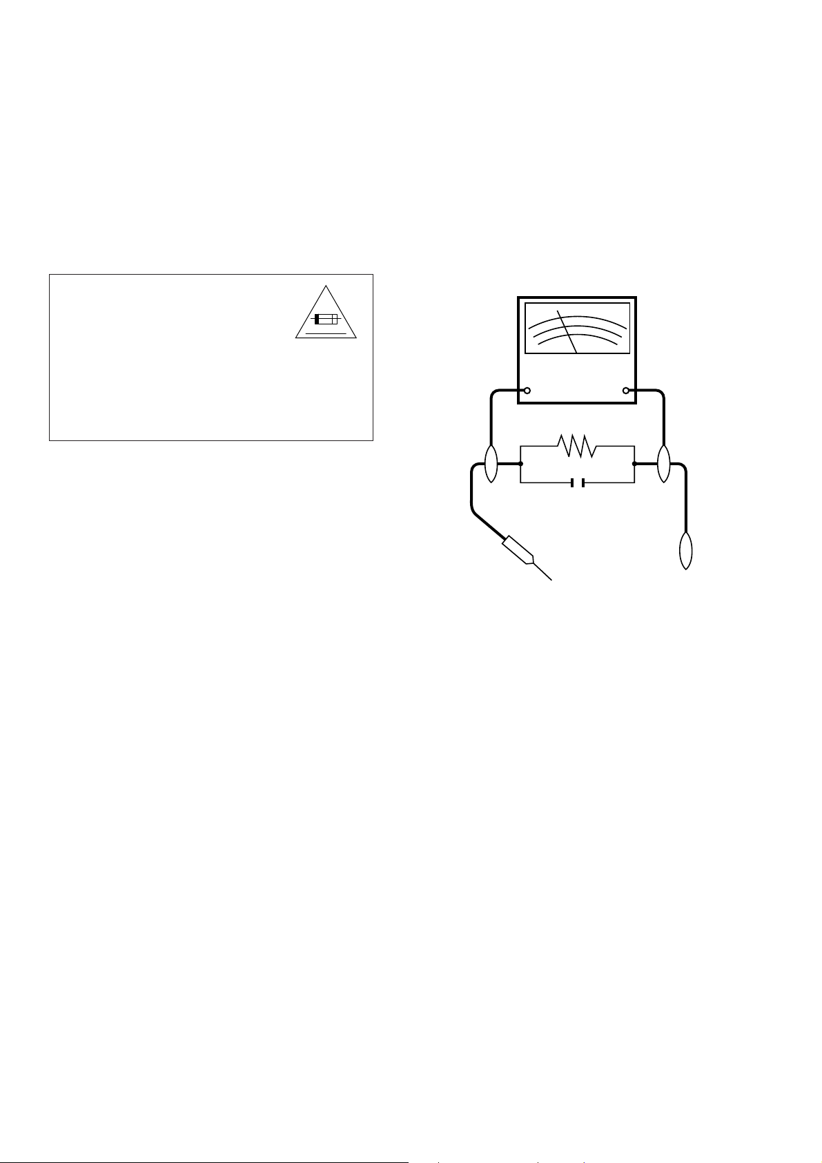
3. To be sure that no shock hazard exists, check for
current in the following manner.
• Plug the AC Adapter directly into a 120-volt AC
outlet, and connect the DC power cable into the
monitor's DC jack. (Do not use an isolation
transformer for this test).
• Using two clip leads, connect a 1.5k ohm, 10
watt resistor paralleled by a 0.15µF capacitor in
series with all exposed metal cabinet parts and
a known earth ground, such as electrical conduit
or electrical ground connected to an earth ground.
• Use an AC voltmeter having with 5000 ohm per
volt, or higher, sensitivity or measure the AC
voltage drop across the resisor.
• Connect the resistor connection to all exposed
metal parts having a return path to the chassis
(antenna, metal cabinet, screw heads, knobs
and control shafts, escutcheon, etc.) and measure the AC voltage drop across the resistor.
All checks must be repeated with the AC Adaptor plug connection reversed.(If necessary, a
nonpolarized adaptor plug must be used only for
the purpose of completing these checks.)
Any reading of 0.3V RMS(this corresponds
to 0.2 milliamp. AC.) or more is excessive and
indicates a potential shock hazard which must
be corrected before returning the receiver to
the owner.
DVM
AC SCALE
1.5k ohms.
10W
0.15 µF
TEST PROBE
TO EXPOSED
METAL PARTS
CONNECT TO
KNOWN EARTH
GROUND
SAFETY NOTICE
Many electrical and mechanical parts in LCD monitor
have special safety-related characteristics.
These characteristics are often not evident from visual
inspection, nor can protection afforded by them be necessarily increased by using replacement components
rated for higher voltage, wattage, etc.
Replacement parts which have these special safety
characteristics are identified in this manual; electrical
components having such features are identified by
“ å” and shaded areas in the
and Schematic Diagrams
For continued protection, replacement parts must be
identical to those used in the original circuit.
The use of a substitute replacement parts which do not
have the same safety characteristics as the factory
recommended replacement parts shown in this service
manual, may create shock. fire. or other hazards.
Replacement Parts Lists
.
2
Page 3

LC-121M2U
LC-150M2U
1. PRECAUTIONS A PRENDRE LORS DE LA REPARATION
ÆÆ
Æ Ne peut effectuer la réparation qu’ un technicien spécialisé qui s’est parfaitement
ÆÆ
accoutumé à toute vérification de sécurité et aux conseils suivants.
LC-121M2U
LC-150M2U
AVERTISSEMENT
1. N’entreprendre aucune modification de tout circuit.
C’est dangereux.
2. Débrancher le récepteur avant toute réparation.
PRECAUTION
POUR LA PROTECTION CONTINUE
CONTRE LES RISQUES D’INCENDIE,
REMPLACER LE FUSIBLE PAR UN FUSIBLE
DE MEME TYPE F701, F703 (1.6A 125V), F702
(2.5A 125V).
5A 125V
VERIFICATIONS CONTRE L’INCENDIE ET LE CHOC ELECTRIQUE
Avant de rendre le récepteur à l’utilisateur,
effectuer les vérifications suivantes.
1. Inspecter tous les faisceaux de câbles pour
s’assurer que les fils ne soient pas pincés ou
qu’un outil ne soit pas placé entre le châssis et
les autres pièces métalliques du récepteur.
2. Inspecter tous les dispositifs de protection comme
les boutons de commande non-métalliques, les
isolants, le dos du coffret, les couvercles ou
blindages de réglage et de compartiment, les
réseaux de résistance-capacité, les isolateurs
mécaniques, etc.
3. S’assurer qu’il n’y ait pas de danger
d’électrocution en vérifiant la fuite de courant, de
la facon suivante:
• Brancher l’adaptateur CA dans la prise CA de
120 V et le câble d’alimentation CC dans le jack
du moniteur. (Ne pas utiliser un transformateur
pour cet essai.)
• A l’aide de deux fils à pinces, brancher une
résistance de 1,5kΩ 10 watts en paralléle avec
un condensateur de 0,15µF en série avec toutes
les pièces métalliques exposées du coffret et
une terre connue comme une conduite électrique
ou une prise de terre branchée à la terre.
• Utiliser un voltmètre CA d’une sensibilité d’au
moins 5000Ω/V pour mesurer la chute de tension en travers de la résistance.
• Raccordez la résistance à toutes les pièces
exposées qui ont un chemin de retour au châssis
(antenne, coffret métallique, têtes de vis, boutons, arbres de commande, emblème, etc) et
mesurez une chute de tension CA à travers la
résistance.
Il faut répéter les vérifications en inversant la
connexion de la fiche de l'adaptateur CA (S'il
y a lieu, utilisez une fiche non polarisée pour
seulement compléter ces vérifications.)
Une valeur de 0,3 V RMS ou plus (correspond
à 0,2 mA C.A.) est excessive et implique un
danger de secousse électrique, qui devra être
supprimé avant de retourner l'appareil à
l'utilisateur.
DVM
Echelle CA
1.5 k ohm
10W
0,15 µF
SONDE D'ESSAI
AUX PIECES
METALLIQUES
EXPOSEES
BRANCHER A UNE
TERRE CONNUE
AVIS POUR LA SECURITE
De nombreuses pièces, électriques et mécaniques, dans
les téléviseurs présentent des caractéristiques spéciales
relatives à la sécurité, qui ne sont souvent pas évidentes
à vue. Le degré de protection ne peut pas être
nécessairement augmentée en utilisant des pièces de
remplacement étalonnées pour haute tension, puissance,
etc.
Les pièces de remplacement qui présentent ces
caractéristiques sont identifiées dans ce manuel; les
pièces électriques qui présentent ces particularités sont
identifiées par la marque “ å” et hachurées dans la liste
des pièces de remplacement et les diagrammes
schématiques.
Pour assurer la protection, ces pièces doivent être
identiques à celles utilisées dans le circuit d’origine.
L’utilisation de pièces qui n’ont pas les mêmes
caractéristiques que les pièces recommandées par
l’usine, indiquées dans ce manuel, peut provoquer des
électrocutions, incendies, radiations X ou autres accidents.
3
Page 4

LC-121M2U
LC-150M2U
2. SPECIFICATIONS
Number of Picture Elements: 921,600 (480 (V) × 640 (H) × 3 (RBG) )
Connected Terminals: Input: DC12V, VHS, S-VHS, Audio and DVD
Power Consumption (Approx.): 38 W (Connected to AC Adapter) (LC-121M2U)
Operating Temparature: –10°C~40°C
LC-121M2U
LC-150M2U
Type: LCD display unit (LCD color AV monitor)
Size: 12.1" type (184.3 mm × 245.8 mm) (LC-121M2U)
15" type (305.3 mm × 229.0 mm) (LC-150M2U)
Display System: Transmitting type TN liquid crystal panel.
Driving System: TFT (Thin Film Transistor) active matrix system
Speaker Output: 0.7 W × 2 (Front)
2 W × 1 (Rear)
Speaker: 30 mm × 40 mm (Elliptic) × 2 (Front)
65 mm (Round) × 1 (Rear)
Light Source: Internal Light (Built-in fluorescent lamp)
Output: VHS, S-VHS, Audio and Headphone
Power Source: AC 100~240·50/60Hz (Connected to AC Adapter)
40 W (Connected to AC Adapter) (LC-150M2U)
Dimensions: 297.4 mm (W) × 264.6 mm (H) × 87 mm (D) (Includes Set Stand)
(LC-121M2U)
357.0 mm (W) × 309.2 mm (H) × 87 mm (D) (Includes Set Stand)
(LC-150M2U)
297.4 mm (W) × 264.6 mm (H) × 62.5 mm (D) (Not Include Set Stand)
(LC-121M2U)
357.0 mm (W) × 309.2 mm (H) × 62.5 mm (D) (Not Include Set Stand)
(LC-150M2U)
Weight (Approx.): 2.9 kg (LC-121M2U)
3.6 kg (LC-150M2U)
Accessories: Operation Manual, Guarantee Card, AC Adapter, Remote Control,
Set Stand Mounting Screws, Wall mounting set angle and Batteries
(AAA size x 2)
Specifications are subject to changed without prior notice.
4
Page 5

LC-121M2U
LC-150M2U
3. PART NAMES
LC-121M2U
LC-150M2U
5
Page 6
LC-121M2U
LC-150M2U
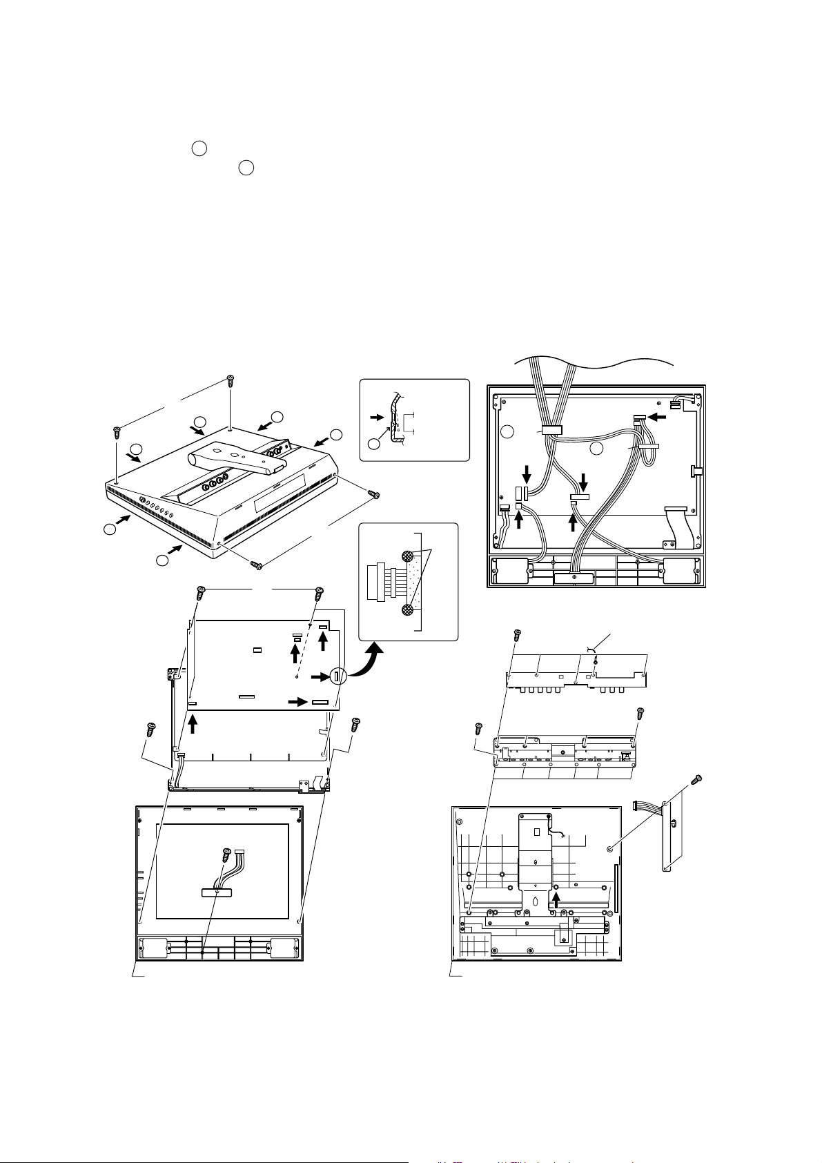
4. DISASSEMBLY OF THE SET
LC-121M2U
LC-150M2U
1. Remove four screws (1).
2. Opening six claws ( a ), release the cabinet B.
Remove the wire holder ( b ) and disconnect each
connectors (2~6).
Remove the cabinet B.
3. Remove two screws (7) which mounting the LCD
display unit.
4. Remove soldering of copper-foil tape (8) .
5. Disconnect each connectors (9~e) from the LCD
display unit.
6. Remove the cabinet A.
Push
1
a
a
a
a
a
7. Remove four screws (r) which mounting the main
PWB unit.
8. Remove one screw (t) and remove the remote control
receptor PWB.
9. Remove five screws (y) and GND cable.
10.Remove ten screws (u) and remove the terminal
cover.
11.Remove two screws (i) and remove the switch PWB.
Cabinet B
Cabinet B
5
Cabinet A
c WH
2
b WH
3
a
a
1
8
4
6
r
y
Cable
q
0
w
7
e
7
9
u
u
i
t
Cabinet A
CCABA2338CE02 GCABA2338CEKA (LC-121M2U)
CCABA2343CE02 GCABA2343CEKA (LC-150M2U)
Cabinet B
CCABB2246CE02 GCABB2246CEKA (LC-121M2U)
CCABB2249CE02 GCABB2249CEKA (LC-150M2U)
6
Page 7
LC-121M2U
LC-150M2U
LC-121M2U
LC-150M2U
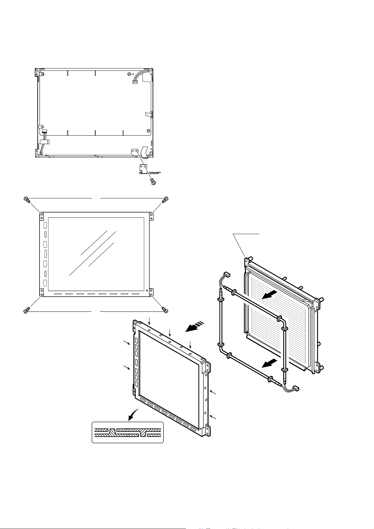
12.Remove one screw (o) and remove the SOS shield
angle.
13. Remove four screws (p) which mounting the LCD
display unit.
14.Spread bites of the LCD unit (a) out to be off from
claws.
15.Remove the Lamp unit (s).
o
p
p
Holder
LHLDZ2082CEKZ (LC-121M2U)
LHLDZ2085CEKZ (LC-150M2U)
s
a
7
Page 8

LC-121M2U
LC-150M2U
5. ADJUSTING PROCEDURE OF EACH SECTION
The best adjustment is made before shipping. If any position deviation is found or after part replace is performed, adjust
as follows.
5-1. Preparation for adjustment
(1)Use the exclusive-use AC adapter or stable DC power supply.
AC adapter: UADP-0183CEZZ
DC power supply: 12 ± 0.5V
5-2. Special mode setting procedure
(1)After initialization of E2PROM the mode is changed to the adjustment mode.
[Procedure]
Connect TP2007 and TP2008 to GND, and turn on the power.
[Description]
• The initialization of microcomputer is as follows.
• AV position, DAC data, G/A data, and video chroma data adjustment values are taken as defaults.
(2)Change to adjustment mode
[Procedure]
Short-circuit TP2007 to GND, and turn on the power.
Or short-circuit TP2008 to GND, and turn on the power.
Or holding down the [AV INPUT] key and [MENU] key, turn on the main power, and simultaneously press the (inspection
process) [SELECT "] key and [VOL– ] key to change the mode to the adjustment mode.
LC-121M2U
LC-150M2U
[Description]
The manual adjustment or adjustment through communication with the automatic machine is performed.
(3)Inspection mode
[Procedure]
Holding down the [AV INPUT] key and [MENU] key, turn on the power.
[Description]
• In the ordinary menu select “PICTURE” with the [SELECT] key, and decide with the [VOL] key. Then select
“CONTRAST”, “TINT (only NTSC)”, “COLOR”, “BLACK LEVEL”, “SHARPNESS”, “RED” , and “BLUE” with the
[SELECT] key, and decide with the [VOL] key. After that, adjust values with the [VOL] key.
• In the ordinary menu select “SOUND” with the [SELECT] key, and decide with the [VOL] key. Then, select “TREBLE”,
“BASS”, and “BALANCE” with the [SELECT] key, and decide with the [VOL] key. After that adjust values with the [VOL]
key.
• VOLUME, CONTRAST, TINT (only NTSC), COLOR, BLACK LEVEL, SHARPNESS, RED, BLUE, TREBLE, BASS,
and BALANCE change as follows.
ûMin.Û ûCenterÛ ûMax.Û
(4)Shipping setting mode
[Procedure]
Holding down the [AV INPUT] key and [MENU] key, turn on the main power, and simultaneously press the (inspection
process) [SELECT '] key and [VOL+] key to change the mode to the adjustment mode.
[Description]
User adjustment and other values are taken as defaults.
If AV1 is indicated as SETTING COMPLETE, setting has been completed.
8
Page 9

LC-121M2U
LC-150M2U
5-3. Cancel of special mode
Turn off the main unit power.
5-4. Preparation adjustment
(1)Use the exclusive-use AC adapter or stable DC power supply.
AC adapter: UADP-0183CEZZ
DC power supply: 12 ± 0.5V
5-5. OSD menu indication and items in case of manual adjustment
Adjusting range
Page Item Minimum Maximum Initial Remarks
1 + B – ADJ 0 255 128
MODEL M2H F2/M2H/M2U/M2E
TUNER OFF 1/2/OFF
AUDIO MULTIPLEX OFF OFF/ON
BOOSTER 0 0/1/2/3
SYSTEM AUTO N358/N443/PAL/PAL-M/SECAM/AUTO
COPY GUARD ON OFF/ON
CH MEMORY OFF OFF/12/16
SECAM ON OFF/ON
MULTI LANG. OFF OFF/ON
TIMER OFF OFF/ON
The Ver. No. will be displayed on the lowest part of lines.
2 TA1276 DATA ~~~~
COM 0 255 128
NTSC/PALM OSC 0 255 128
N358 BRIGHTNESS 0 255 170
R CUTOFF 0 255 80
B CUTOFF 0 255 80
N358UNICOLOR 0 127 80
R DRIVE 0 127 64
B DRIVE 0 127 64
N358SCOLOR 0 31 25
N358TINT 0 127 74
DATA COPY WAIT WAIT/SEND
3 N358 R-Y PHASE 0 3 2
N358 B-Y PHASE 0 3 1
N443 BRIGHTNESS 0 255 170
N443 UNICOLOR 0 127 80
N443 SCOLOR 0 31 25
N443TINT 0 127 74
PAL-M BRIGHTNESS 0 255 170
PAL-M UNICOLOR 0 127 80
PAL-M SCOLOR 0 31 25
PAL-M TINT 0 127 74
R-ADJ 0 255 128
One blank line.
LC-121M2U
LC-150M2U
9
Page 10

LC-121M2U
LC-150M2U
4 PAL/SECAM OSC 0 255 128
5 DVD NT BRIGHTNESS 0 255 170
6 TEST PATTERN OFF ON/OFF
7 N443 R-YPHASE 0 3 2 Fixed
PAL BRIGHTNESS 0 255 170
PAL UNICOLOR 0 127 80
PAL SCOLOR 0 31 25
PAL TINT 0 127 74
BELL F0 0 255 120
B-Y BLACK LEVEL 0 15 8
R-Y BLACK LEVEL 0 15 8
SECAM BRIGHTNESS 0 255 170
SECAM UNICOLOR 0 127 80
SECAM COLOR 0 127 75
SECAM TINT 0 127 74
DVD NT UNICOLOR 0 127 80
DVD NT COLOR 0 127 75
DVD NT TINT 0 127 74
DVD NT R-YPHASE 0 3 2
DVD NT B-YPHASE 0 3 3
DVD PAL BRIGHTNESS
DVD PAL UNICOLOR 0 127 80
DVD PAL COLOR 0 127 75
DVD PAL TINT 0 127 74
I2C DATA 000000
I2C DATA WAIT WAIT/SEND
G/A DATA 0000
G/A DATA WAIT WAIT/SEND
DIGITAL SYNC SEP. 0 FF 87 Fixed
AV NTSC H 0 7F 18 Fixed
DVD NTSC H 0 7F 1C Fixed
AV PAL H 0 7F 11 Fixed
DVD PAL H 0 7F 15 Fixed
AV SECAM H 0 7F 0E Fixed
NT/PALM V 1 1F 0C Fixed
PAL V 1 1F 0B Fixed
SECAM V 1 1F 0B Fixed
N443 B-YPHASE 0 3 1 Fixed
PAL R-YPHASE 0 3 2 Fixed
PAL B-YPHASE 0 3 1 Fixed
PAL-M R-YPHASE 0 3 2 Fixed
PAL-M B-YPHASE 0 3 1 Fixed
SECAM R-YPHASE 0 3 2 Fixed
SECAM B-YPHASE 0 3 1 Fixed
DVD PAL R-YPHASE 0 3 2 Fixed
DVD PAL B-YPHASE 0 3 1 Fixed
COLOR 0 127 60 Fixed
SCONT 0 31 18 Fixed
0 255 170
LC-121M2U
LC-150M2U
10
Page 11

LC-121M2U
LC-150M2U
8 DAC 2 1ch 0 255 0 Fixed
DAC 2 2ch 0 255 0 Fixed
DAC 2 3ch 0 255 0 Fixed
DAC 2 4ch 0 255 0 Fixed
DAC 2 5ch 0 255 0 Fixed
DAC 2 6ch 0 255 0 Fixed
DAC 2 7ch 0 255 0 Fixed
DAC 2 8ch 0 255 0 Fixed
DAC 2 9ch 0 255 0 Fixed
DAC 2 10ch 0 255 0 Fixed
DAC 2 11ch 0 255 0 Fixed
DAC 2 12ch 0 255 0 Fixed
5-6. Service Adjusting
5-6-1. Basic Adjustment
1 +B Adjustment 1. Connect the DC voltmeter to 1. Adjust +B-ADJ to 5.1V ± 0.05V.
LC-121M2U
LC-150M2U
Adjustment Adjusting conditions Adjusting method
TP1104 ( DAC 9ch )
2 Model setup 1. Select the model "M2U". When M2U is selected, the item
settings are as follows.
TUNER OFF
AUDIO MULTIPLEX OFF
BOOSTER 0
SYSTEM AUTO
COPY GUARD ON
CH MEMORY OFF
SECAM ON
MULTI LANG. OFF
TIMER OFF
3 Counter-bias adjustment 1. Set the AV1 mode to set signal 1. Adjust COM so as to minimize the
noninput state. waveform peak-peak.
2. Fit the specified adjusting instrument (DAC7ch)
to the screen center.
3. Observe the adjusting instrument
output on the oscilloscope.
4 NTSC / PAL-MOSC 1. Input the monoscope pattern of 1. Adjust NTSC/PALM OSC so as to
adjustment NTSC into AV1. get the normal screen.
(DAC8ch)
11
Page 12
LC-121M2U
LC-150M2U
5-6-2. AV input Adjustment
Adjustment Adjustment conditions Adjustment method
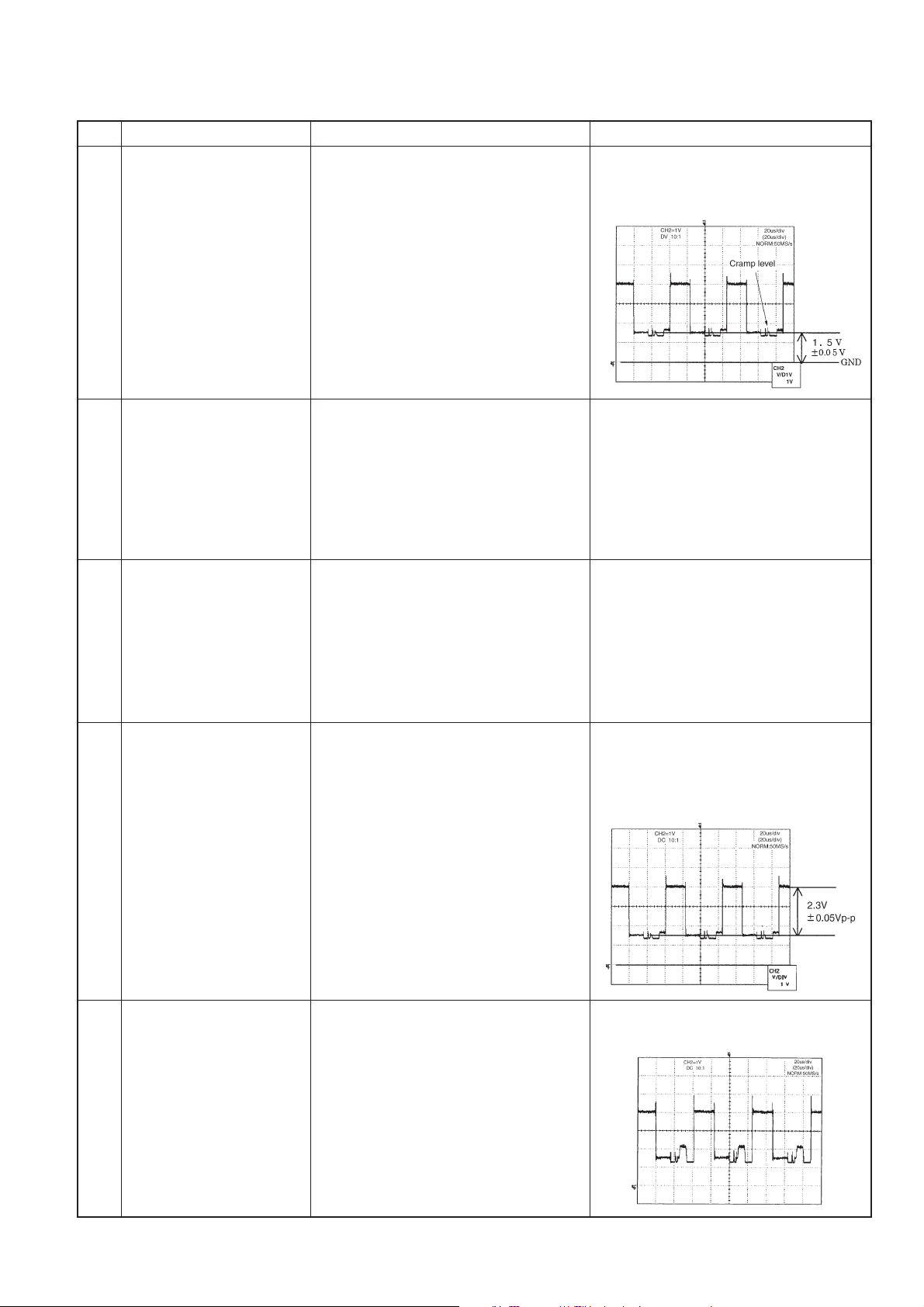
1 Brightness adjustment 1. Input the standard color bar signal 1. Adjust N358 BRIGHTNESS, and
(N358) (the same pattern as that of JPN-8CH) adjust the black level of G output so
2 R-cut off adjustment 1. Input the standard color bar signal 1. Adjust R CUTOFF so as to equalize
3 B-cut off adjustment 1. Input the standard color bar signal 1. Adjust B CUTOFF so as to equalize
4 Unicolor adjustment 1. Input the standard color bar signal 1. Adjust N358UNICOLOR, and
(N358) (the same pattern as that of JPN- adjust so as to get 100% white-
LC-121M2U
LC-150M2U
of N358 into AV1. as to get DC 1.5±0.05V.
2. Connect the oscilloscope to TP821
(IC803, pin7, G output).
(the same pattern as that of JPN-8CH) the black levels of green and red.
of N358 into AV1.
2. Connect the oscilloscope to TP821
(IC803, pin7, G output).
3. Connect the oscilloscope to TP819
(IC803, pin1, R output).
(the same pattern as that of JPN-8CH) the black levels of green and blue.
of N358 into AV1.
2. Connect the oscilloscope to TP821
(IC803, pin7, G output).
3. Connect the oscilloscope to TP820
(IC803, pin8, B output).
8CH) of N358 into AV1. black level video component equal
2. Connect the oscilloscope to TP821 to 2.3±0.05Vp-p.
(IC803, pin7, G output).
5 R DRIVE adjustment 1. Input the standard color bar signal 1. Adjust so as to get 100% white level
(the same pattern as that of JPN- identical with that of green.
8CH) of N358 into AV1.
2. Connect CH1 of oscilloscope to
TP821 (G output).
3. Connect CH2 of oscilloscope to
TP819 (R output).
12
Page 13
LC-121M2U
LC-150M2U
6 B DRIVE adjustment 1. Input the standard color bar signal 1. Adjust so as to get 100% white level
7 Color level adjustment 1. Input the standard color bar signal Adjust N358 SCOLOR so as to get the
LC-121M2U
LC-150M2U
(the same pattern as that of JPN- identical with that of green.
8CH) of N358 into AV1.
2. Connect CH1 of oscilloscope to
TP821 (G output).
3. Connect CH2 of oscilloscope to
TP820 (B output).
(N358) (the same pattern as that of JPN- color bar signal blue amplitude
8CH) of N358 into AV1. (black level - peak level) equal to 2.5V
2. Connect the oscilloscope to TP820 ± 0.05Vp-p.
(B output).
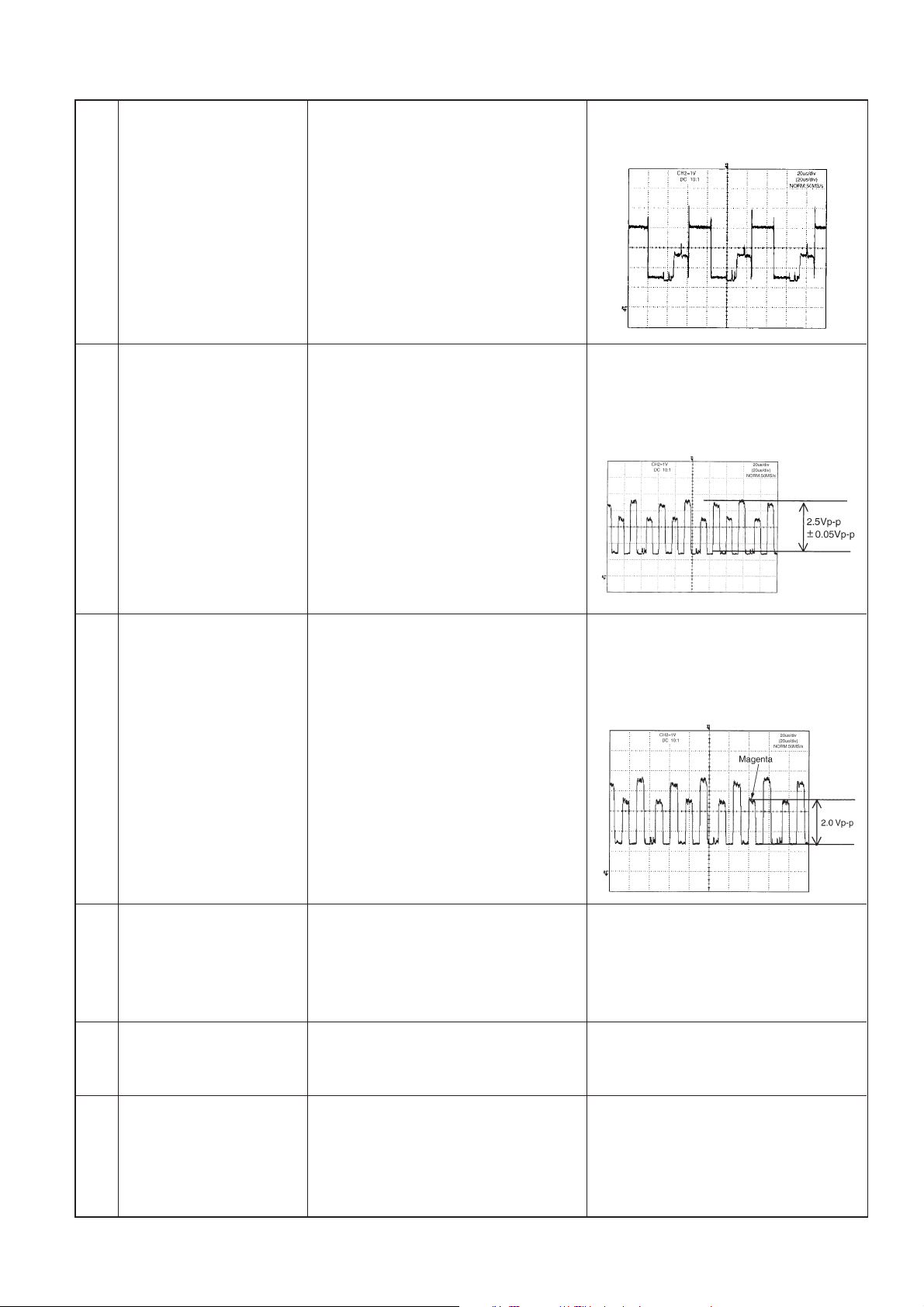
8 Tint adjustment 1. Input the standard color bar signal 1. Adjust N358 TINT so as to get the
(N358) (the same pattern as that of JPN- color bar signal magenta amplitude
8CH) of N358 into AV1. (black level-peak level) equal to 2.0
2. Connect the oscilloscope to TP820 ± 0.05Vp-p.
(B output).
9 N443/PAL-M adjustment 1. Position the cursor on DATA COPY 1. The indication changes from WAIT
and press VOL key. to SEND, and after the lapse of one
second WAIT is restored. Thus, N443,
PAL-M adjustment is completed.
10 4V adjustment 1. Connect the DC voltmeter to TP1110 1. Adjust R-ADJ to 4.0V ± 0.05V.
( DAC 6ch )
11 PAL/SECAM OSC 1. Input the monoscope pattern of PAL 1. Adjust PAL/SECAM OSC so as to
adjustment into AV1. get the normal screen.
(DAC8ch)
13
Page 14

LC-121M2U
LC-150M2U
12 Brightness adjustment 1. Input the standard color bar signal 1. Adjust PAL BRIGHTNESS, and
13 Unicolor adjustment 1. Input the standard color bar signal 1. Adjust PAL UNICOLOR, and adjust
LC-121M2U
LC-150M2U
(PAL) of PAL into AV1. adjust the black level of G output
2. Connect oscilloscope to TP821 so as to get DC 1.5 ±0.05V.
(IC803, pin7, G output).
(PAL) of PAL into AV1. so as to get 100% white-black level
2. Connect oscilloscope to TP821 video component equal to 2.3±0.05
(IC803, pin7 , G output ). Vp-p.
14 Color level adjustment 1. Input the standard color bar signal Adjust PAL SCOLOR so as to get the
(PAL) (the same pattern as that of E-12CH) color bar signal blue amplitude
of PAL into AV1. (black level - peak level) equal to 2.5V
2. Connect the oscilloscope to TP820 ±0.05Vp-p.
(B output).
15 Tint adjustment 1. Input the standard color bar signal 1. Adjust PAL TINT so as to get the color
(PAL) (the same pattern as that of E-12CH) bar signal magenta amplitude (black
of PAL into AV1. level-peak level) equal to 2.0±
2. Connect the oscilloscope to TP820 0.05Vp-p.
(B output).
14
Page 15

LC-121M2U
LC-150M2U
16 BELL f0 adjustment 1. Connect the oscilloscope to 1. Adjust BELL f0 so as to minimize the
17 Brightness adjustment 1. Input the standard color bar signal 1. Adjust SECAM BRIGHTNESS, and
18 Unicolor adjustment 1. Input the standard color bar signal 1. Adjust SECAM UNICOLOR, and
LC-121M2U
LC-150M2U
TP2851. a-level.
(SECAM) (the same pattern as that of E-10CH) adjust the black level of G output to
of SECAM into AV1. DC 1.5±0.05V.
2. Connect oscilloscope to TP821
(IC803, pin7, G output).
(SECAM) (the same pattern as that of E-10CH) adjust so as to get 100% white-black
of SECAM into AV1. level video component equal to 2.3±
2. Connect oscilloscope to TP821 0.05Vp-p.
(IC803, pin7, G output ).
19 Color level adjustment 1. Input the standard color bar signal Adjust SECAM COLOR so as to get
(SECAM) (the same pattern as that of E-10CH) the color bar signal blue amplitude
of SECAM into AV1. (black level - peak level) equal to 2.5V
2. Connect the oscilloscope to TP820 ±0.05Vp-p.
(B output).
20 Tint adjustment 1. Input the standard color bar signal 1. Adjust SECAM TINT so as to get
(SECAM) (the same pattern as that of E-10CH) the color bar signal magenta amplitude
of SECAM into AV1. (black level - peak level) equal to 2.0V
2. Connect the oscilloscope to TP820 ±0.05Vp-p.
(B output).
15
Page 16

LC-121M2U
LC-150M2U
5-6-3. Component input Adjustment
Adjustment Adjusting conditions Adjusting method
1 Brightness adjustment 1. From SG, input the 100% white color Adjust DVD NT BRIGHTNESS, and
(NTSC) bar signal of NTSC into conponent adjust the black level of G output so
2 Unicolor adjustment 1. From SG, input the 100% white color Adjust DVD NT UNICOLOR, and
(NTSC) bar signal of NTSC into conponent adjust so as to get 100% white-
LC-121M2U
LC-150M2U
terminal. as to get DC 1.5±0.05V.
2. Connect oscilloscope to TP821
(IC803, pin7, G output).
terminal. black level video component equal
2. Connect oscilloscope to TP820 to 2.3±0.05Vp-p.
(IC803, pin8).
3 Color level adjustment 1. From SG, input the 100% white color Adjust DVD NT COLOR so as to get
(NTSC) bar signal of NTSC into conponent the color bar signal blue amplitude
terminal. (black level - peak level) equal to
2. Connect the oscilloscope to TP820 2.8V±0.05Vp-p.
(B output).
4 Tint adjustment 1. From SG, input the 100% white color Adjust DVD NT TINT so as to get the
(NTSC) bar signal of NTSC into conponent color bar signal magenta amplitude
terminal. (black level - peak level) equal to 2.3V
2. Connect the oscilloscope to TP820 ±0.05Vp-p.
(B output).
16
Page 17

LC-121M2U
LC-150M2U
5 Brightness adjustment 1. From SG, input the 100% white color Adjust DVD PAL BRIGHTNESS, and
6 Unicolor adjustment 1. From SG, input the 100% white color Adjust DVD PAL UNICOLOR, and
LC-121M2U
LC-150M2U
(PAL) bar signal of PAL into conponent adjust the black level of G output so
terminal. as to get DC 1.5±0.05V.
2. Connect oscilloscope to TP821
(IC803, pin7, G output).
(PAL) bar signal of PAL into conponent adjust so as to get 100% white-
terminal. black level video component equal
2. Connect oscilloscope to TP820 to 2.3±0.05Vp-p.
(IC803, pin8, B output).
7 Color level adjustment 1. From SG, input the 100% white color Adjust DVD PAL COLOR so as to get
(PAL) bar signal of PAL into conponent the color bar signal blue amplitude
terminal. (black level - peak level) equal to
2. Connect the oscilloscope to TP820 2.8V±0.05Vp-p.
(B output).
8 Tint adjustment 1. From SG, input the 100% white color Adjust DVD PAL TINT so as to get
(PAL) bar signal of PAL into conponent the color bar signal magenta amplitude
terminal. (black level - peak level) equal to
2. Connect the oscilloscope to TP820 2.3V±0.05Vp-p.
(B output).
9 Tint adjustment Position the cursor on N358 TINT. Lower unconditionally the value by
10 points.
17
Page 18

LC-121M2U
LC-150M2U
5-7. Shipping setting
(1)[Procedure]
Holding down the [AV INPUT] key and [MENU] key, turn on the main power, and simultaneously press the (inspection
process) [SELECT '] key and [VOL+] key to change the mode to the adjustment mode.
(2)[Indication]
AV1 is indicated as SETTING COMPLETE.
(3)[Description]
Mode is memorized as SETTING COMPLETE.
Menu setting descriptions are as follows.
VOLUME 30
CONTRAST 30 (AV1 / AV2 / COMPONENT)
TINT 0 (AV1 / AV2 / COMPONENT) (ONLY NTSC)
COLOR 0 (AV1 / AV2 / COMPONENT)
SHARPNESS 0 (AV1 / AV2 / COMPONENT)
RED 0 (AV1 / AV2 / COMPONENT)
BLUE 0 (AV1 / AV2 / COMPONENT)
COLOR SYSTEM AUTO (AV1 / AV2 / COMPONENT)
TREBLE 0
BASS 0
BALANCE 0
BRIGHTNESS BRIGHT
UPSIDE NORMAL
RIGHT / LEFT NORMAL
AV2 IN / OUT IN
LC-121M2U
LC-150M2U
AV1
SETTING COMPLETE
18
Page 19

LC-121M2U
LC-150M2U
6. INTEGRATED CIRCUIT TERMINAL ARRANGEMENTS
1. IC2001 (QFP, 80pins)
Terminal No. Terminal name I/O Function
1 N. C –
2 N. C –
3 KEY3 I Key input 3
4 KEY4 I Key input 4
5 HPDET I Headphon input pickup
6 M O Audio selection 1
7 S O Audio selection 2
8 MONO O Forced monophonic
9 FSMUT O Front speaker MUTE output
10 RSMUT O Rear speaker MUTE output
11 N. C –
12 N. C –
13 CSYNC I Composite sync signal input
14 IFAGC I IFAGC input
15 PLCS O TV PLL chip select output
16 MRDY I I2C bus opening/connection selection input
17 PLLD I TV-PLL lock signal input
18 LMUTE O Lineout-Mute output
19 SCLK I/O Serial clock signal
20 SOUT O Serial data output
21 AFT I AFT voltage input
22 AGC I AGC input voltage
23 SCL I/O I2C bus serial clock line
24 SDA I/O I2C bus serial data line
25 N. C –
26 N. C –
27 CNV s s GND connection
28 φ O Timing output
29 RESET I Change to “Reset mode” in “L” state
30 Xin I Microcomputer oscillator connection
31 Xout O Microcomputer oscillator connection
32 V s s I GND
33 PSW I Power switch input
34 POW O DC/DC control output
35 COCS O G/A chip selection output
36 DACS O D/A chip selection output
37 BOOST O Booster selection output
38 BOOLV O Booster level selection output
39 N. C –
40 N. C –
41 DA2CS O D/A 2 chip selection output
42 AV1/AV2 O Analog SW selection 1
43 AV/S O Analog SW selection 2
44 Y/COM O Analog SW selection 3
45 IN/OUT O Analog SW selection 4
46 REQ O “H” in [ADJUSTMENT] mode, “L” in other modes.
LC-121M2U
LC-150M2U
19
Page 20

LC-121M2U
LC-150M2U
LC-121M2U
LC-150M2U
Terminal No. Terminal name I/O Function
47 Empty I
48 STB O Micro computer power off output
49 SECAM O “H” in SECAM mode, “L” in other modes.
50 PAL O “H” in PAL mode, “L” in other modes.
51 N. C –
52 N. C –
53 N. C –
54 SAFE I Parking input
55 Empty I
56 Empty I
57 Empty I
58 Empty I
59 Empty I
60 Empty I
61 N. C I
62 BLK OSD blanking output
63 N. C I
64 N. C –
65 N. C –
66 BOUT O B signal output
67 GOUT O G signal output
68 ROUT O R signal output
69 Vsync I OSD virtical sync signal input
70 Hsync I OSD horizontal sync signal input
71 N. C –
72 V c c I Positive voltage power terminal
73 N. C –
74 OSC1 OSD clock
75 OSC2 OSD clock
76 N. C –
77 KEY 1 I Key input1
78 KEY 2 I Key input2
79 IREM I Ir Remotecontrol input
80 ST/MT I Broadcast mode input
20
Page 21

LC-121M2U
LC-150M2U
2. IC1201 (QFP, 128pins)
Terminal No. Voltage I/O Signal name Function
1 5.0V I OSD_BK OSD Blanking input
2 5.0V I OSD_R OSD R input
3 5.0V I OSD_G OSD G input
4 5.0V I OSD_B OSD B input
5 5.0V O OSDVD OSD V output
6 5.0V O OSDHD OSD H output
7 5.0V O OSDCK OSD clock output
8 5.0V O VCIHD Horizontal sync output(VCI)
9 5.0V GND
10 5.0V VCC
11 5.0V O OFL PWM output (Inverter)
12 5.0V I MP_DA 3-wire serial data input
13 5.0V I MP_CK 3-wire serial clock input
14 5.0V I MP_CS 3-wire serial chip selection input
15 5.0V I TVAV Copy guard ON/OFF input
16 5.0V I FREE Inside/outside sync selection input
17 5.0V I CSYNC Composit signal input
18 5.0V O PDP PLL control signal output
19 5.0V GND
20 5.0V I OSCI PLL ocsillation input
21 5.0V O OSCO PLL ocsillation output
22 5.0V VCC
23 5.0V GND
24 5.0V O OHSYN Sync separation output
25 5.0V O DVDO Digital sync separation output
26 5.0V I VSYN Virtical sync signal input
27 5.0V I GST Reset input
28 5.0V GND
29 5.0V O REV Graduation power control signal output 1
30 5.0V O REVV0 Graduation power control signal output 2
31 5.0V O GSP1 Gate driver controll signal output 1
32 5.0V O GCK Gate driver controll signal output 2
33 3.3V GND
34 3.3V O OOR7 R output 7 (MSB)
35 3.3V O OOR6 R output 6
36 3.3V O OOR5 R output 5
37 3.3V O OOR4 R output 4
38 3.3V O OOR3 R output 3
39 3.3V O OOR2 R output 2
40 3.3V O OOR1 R output 1
41 3.3V O OOR0 R output 0 (LSB)
42 3.3V GND
43 3.3V O OOG7 G output 7 (MSB)
44 3.3V O OOG6 G output 6
45 3.3V O OOG5 G output 5
46 3.3V O OOG4 G output 4
47 3.3V O OOG3 G output 3
48 3.3V O OOG2 G output 2
LC-121M2U
LC-150M2U
21
Page 22

LC-121M2U
LC-150M2U
Terminal No. Voltage I/O Signal name Function
LC-121M2U
LC-150M2U
49 3.3V GND
50 3.3V VCC
51 3.3V O HDCK SOURCE driver control signal output 1
52 3.3V O OCK SOURCE driver control signal output 2
53 3.3V GND
54 3.3V O OOG1 G output 1
55 3.3V O OOG0 G output 0 (LSB)
56 3.3V O OOB7 B output 7 (MSB)
57 3.3V O OOB6 B output 6
58 3.3V O OOB5 B output 5
59 3.3V O OOB4 B output 4
60 3.3V GND
61 3.3V O OOB3 B output 3
62 3.3V O OOB2 B output 2
63 3.3V O OOB1 B output 1
64 3.3V O OOB0 B output 0 (LSB)
65 3.3V GND
66 3.3V O SPLS SOURCE driver control signal output 3
67 3.3V O SPRS SOURCE driver control signal output 4
68 3.3V O LBR SOURCE driver control signal output 5
69 3.3V O HGO SOURCE driver control signal output 6
70 3.3V I NBH CCW/CW inversion input
H:Inversion, L:Normal rotation
71 3.3V I NTSC NTSC/PAL selection input H:PAL, L:NTSC
72 3.3V GND
73 3.3V O TM0 Gate driver control signal output 3
74 3.3V O TM1 Test output 1
75 3.3V O TM2 Test output 2
76 3.3V VCC
77 3.3V GND
78 3.3V I R0 R input 0 (LSB)
79 3.3V I R1 R input 1
80 3.3V I R2 R input 2
81 3.3V I R3 R input 3
82 3.3V I R4 R input 4
83 3.3V I R5 R input 5
84 3.3V I R6 R input 6
85 3.3V I R7 R input 7 (MSB)
86 3.3V GND
87 3.3V I G0 G input 0 (LSB)
88 3.3V I G1 G input 1
89 3.3V I G2 G input 2
90 3.3V I G3 G input 3
91 3.3V I G4 G input 4
92 3.3V I G5 G input 5
93 3.3V I G6 G input 6
94 3.3V I G7 G input 7 (MSB)
95 3.3V O TM3 Test output 3
96 3.3V O TM4 Test output 4
22
Page 23

LC-121M2U
LC-150M2U
Terminal No. Voltage I/O Signal name Function
LC-121M2U
LC-150M2U
97 3.3V GND
98 3.3V I TST8 Test input 8
99 3.3V I TST7 Test input 7
100 3.3V I TST6 Test input 6
101 3.3V I TST5 Test input 5
102 3.3V I TST4 Test input 4
103 3.3V I TST3 Test input 3
104 3.3V I TST2 Test input 2
105 3.3V I TST1 Test output 1
106 3.3V I TSH VCI horisontal sync signal input
107 3.3V GND
108 3.3V O ADCK A/D converter clock output
109 3.3V I TST9 GND
110 3.3V I PMODE Sync signal
Positive polarity/Negative polarity selection input
H:Positive polarity L:Negative polarity
111 3.3V I DINV Input signal
Primary colors/complementary colors selection input
H:Complementary colors input,
L:Primary colors input
112 3.3V VCC
113 3.3V GND
114 3.3V I B 0 B input 0 (LSB)
115 3.3V I B 1 B input 1
116 3.3V I B 2 B input 2
117 3.3V I B 3 B input 3
118 3.3V I B 4 B input 4
119 3.3V I B 5 B input 5
120 3.3V I B 6 B input 6
121 3.3V I B 7 B input 7 (MSB)
122 3.3V GND
123 3.3V O OCVD Virtical synchro signal output
124 3.3V I TSV Virtical synchro signal input
125 3.3V O MASK
126 3.3V O OSCO2 Clock output (No use)
127 3.3V I OSCI2 Clock input (No use)
128 3.3V GND
23
Page 24

LC-121M2U
No picture, No sound
Do F701 and F703 function?
Check T701's secondary load.
Check IC702, Q702, L701
and their peripheral parts.
Remove F701 and F703, and
check the load side.
Is there short-circuiting?
Is there short-circuiting of T701
primary side periphery, Q701
and S701?
Replace F701 and F703.
YES
NO
YES
YES
YES
NO
NO
Check Q751, Q752, Q753,
Q754, T751, T752 and their
peripheral parts.
Check Q703 and its peripheral
parts.
Replace the fluorecent lamp
with new one and check again.
Is primary oscillator waveform
of T751 and T752 normal ?
Does Q703 function?
Does output voltage +9V
appear?
Does F702 function?
Fluorecent lamp failure to light up.
YES
YES
YES
NO
NO
NO
Are T701's secondary outputs,
+30V, +23V, +9V, +5.1V and
-5.5V normal?
Is T701's primary oscillator
waveform normal?
LC-150M2U
7. TR OUBLESHOO TING
LC-121M2U
LC-150M2U
24
Page 25

LC-121M2U
Check IC406, IC403 and their peripheral parts.
No picture (AV1, AV2 and Component)
Is output voltages
at pins 3,5 and 6 of
IC406 normal?
Is input voltages at
pins 51,52 and 53
of IC801 normal?
Is output voltages at
pins 41,42 and 43
of IC801 normal?
Is output voltages
at pins 1,7 and 8 of
IC803 normal?
No picture (AV1, AV2)
Replace LCD module with new one and check again.
Replace cables with new one and check again.
No picture
Check the in/output
of IC406 and its
peripheral parts.
No picture (AV1/AV2)
No picture (Component)
Is signal input into the pin
13 of IC2001?
Check IC406 and
its peripheral parts.
Check IC801 and
its peripheral parts.
Check IC803 and
its peripheral parts.
Is in/output voltages of IC1001 normal?
Is in/output voltages of IC1201 normal?
Are voltages and waveform of the LCD module connecting connector normal?
Aren't cables break down?
Is in/output voltages
of IC401 normal?
Check IC401 and
its peripheral parts.
Is output voltage at pin 18 of IC801 normal?
Is input voltages at pins 33 and 15 of
IC801 normal?
Check IC401 and
its peripheral parts.
Is output voltages
at pins 23 and 25
of IC851 normal?
Check IC851,
Q852, Q854, Q857
and their peripheral
parts.
Check IC403,
IC405 and their
peripheral parts.
Check IC801 and
its peripheral parts.
Are output voltages
at pin 7 of IC403 and
it of IC405 normal?
Check Q801, Q802
and their peripheral
parts.
Is input voltages
at pins 13 and 15
of IC801 normal?
Is output voltages
at pins 4,5 and 6
of IC801 normal?
Check in/output voltages of IC406
and its peripheral parts.
NO
No picture apears (AV1)
YES
YES
YES
YES
YES
YES
YES
YES
NO
NO
NO
NO
NO
NO
NO
NO
NO
NO
Check Q401~Q406 and
their peripheral parts.
Check peripheral
parts.
YES YES
NO
NO
YES
YES
YES
YES
YES
LC-150M2U
LC-121M2U
LC-150M2U
25
Page 26

LC-121M2U
No sound
Check speaker
unit and its
peripheral parts.
Check IC305 and
its peripheral
parts.
Check IC704,
Q704, Q706 and
their peripheral
parts.
Check IC310,
IC311 and their
peripheral parts.
Are output at pin
7 of IC310 and it
of IC311 normal?
Check speaker
unit and its
peripheral parts.
Check IC312 and
its peripheral
parts.
Is output at pins
3 and 5 of IC308
normal?
Is output at pins
10 and 17 of
IC305 normal?
Check IC305
and its peripheral
parts.
Check IC308
and its peripheral
parts.
Is the pin 18 of
IC2001 in Low
state?
Is output at pins
7 and 18 of
IC312 normal?
Is output at pins
10,14 and 17 of
IC305 normal?
Is 13V input at
pin 9 of IC305
as specified?
Is the pin 9 of
IC2001 in Low
state?
Muting is applied.
Check the
FSMUT line.
YES
YES
YES
YES
YES
YES
YES
YES
Check IC302,
Q301, Q302
and their
peripheral parts.
YES
YES
NO
NO
NO
NO
NO
NO
NO
NO
Check IC305
and its
peripherals.
Check Q306,
Q307, IC304 and
their peripherals.
NO
NO
YES
Muting is applied.
Check the
LMUTE line.
No sound (Front
and rear speaker)
No sound
(AV1 output)
No sound
(Front speaker)
Check speaker
and its
peripherals.
Are Q306, Q307
and IC304
normal?
Is output at pin
14 of IC305
normal?
Is the pin 10 of
IC2001 in Low
state?
YES
YES
YES
YES
No sound
(Rear speaker)
LC-150M2U
LC-121M2U
LC-150M2U
26
Page 27

LC-121M2U
Check in/output voltages of IC406.
YES
No color appears
No color (AV1, AV2 and Component)
Is output voltages
at pins 3 and 6 of
IC406 normal?
Check peripherals.
Are these voltages
as follows of IC801
normal?
pins 51 and 52
(input)
pins 41, 42 and
43 (output)
Check IC801 and
its peripheral
parts.
No color (AV1, AV2)
Is output voltages
at pin 7 of IC405
normal?
Is input voltages
at pin 13 of
IC801 normal?
Is output voltages
at pins 5 and 6 of
IC801 normal?
Check in/output
voltages of IC406.
Check IC405 and
its peripheral
parts.
Check peripherals.
No color (Component)
YES
YES
YES
NO
NO
NO
NO
NO
Check IC801 and
its peripheral
parts.
LC-150M2U
LC-121M2U
LC-150M2U
27
Page 28

LC-121M2U
No color appears
(N358)
Is 3.5795 MHz
input into the
pin 10 of IC801?
Check X801 and
its peripheral
parts.
No color appears
(N443,PAL)
YES
Is the C/Y signals at pins 13 and 15 of IC801 normal ?
Is the output at pins 10 and 11 of IC2802 normal ?
NO
Check X802 and
its peripheral
parts.
NO
Is 4.4336 MHz
input into the
pin 8 of IC801?
YES
YES
Check
Peripheral
parts of IC853.
NO
Is the composite
signal which is
input into the pins
13 and 15 of
IC801 normal?
Check Peripheral
parts of IC853.
NO
YES
Is 4 MHz input
into the pin 8 of
IC2802?
Check X2850
and its peripheral
parts.
NO
YES
Check Peripheral
parts of IC2802.
NO
Is the output at pins 29 and 30 of IC2801 normal ?
Is the output at pins 51 and 52 of IC801 normal ?
Check Peripheral parts of IC801.
YES
Check Peripheral
parts of IC2801.
YES
YES
NO
Check Peripheral
parts of IC406.
NO
No color appears
(PAL-M)
Check X803 and
its peripheral
parts.
NO
Is 3.5756 MHz
input into the
pin 9 of IC801?
YES
No color appears
(SECAM)
Check X802 and
its peripheral
parts.
NO
Is 4.4336 MHz
input into the
pin 8 of IC801?
YES
LC-150M2U
LC-121M2U
LC-150M2U
28
Page 29

LC-121M2U
LC-150M2U
8. CHASSIS LAYOUT
LC-121M2U
LC-150M2U
H
G
F
IC305 Power AMP.
P303
P752
P403
IC2801
1H Dilay system
SECAM decoder
IC2802
X2850
IC853
Digital comb filter
P402
P302
F703 1.6A 125V
IC801 Chroma decoder
RED
BLUE
X802
T701
DC/DC Transformer
BLACK
X803
X801
F701
125V 1.6A
F702 2.5A 125V
TP805
TP1106
TP1112
TP804
TP1111
P2002
P2001
P801
Micon
IC2001
P751
T751
T752
Inverter transformer
SC1202
IC1201
Controller
SC1201
E
D
IC312
Audio control
C
B
IC1001
AD converter
A
123456
29
Page 30

LC-121M2U
LC-150M2U
• DESCRIPTION OF SCHEMATIC DIAGRAM
1. When the exclusive-use AC adapter is used, the color bar signal of color bar generator for service is input
to get the normal screen. When the audio is minimized, the voltage value is measured with the 20 kΩ/V tester.
2. When the exclusive-use AC adapter is used, the color density, lightness and color hue are set to the center
position, and the signal of color bar generator for service is observed to get waveform.
The waveform test point is indicated with the mark ( ) in the wiring diagram.
3. Indication of resistors and capacitors
[Resistor]
Unit: Nonindication ··· Ω, K ··· kΩ,
M ··· MΩ
Error: Nonindication ··· ±10%
J ··· ±5%
F ··· ±1%
D ··· ±0.5%
[Capacitor]
Unit: Nonindication or µ ··· µF,
P or p ··· pF
IMPORTANT SAFETY NOTICE:
PARTS MARKED WITH " å"
IMPORTANT FOR MAINTAINING THE SAFETY
OF THE SET.
BE SURE TO REPLACE THESE PARTS WITH
SPECIFIED ONES FOR MAINTAINING THE SAFETY AND PERFORMANCE OF THE SET.
( )
CAUTION:
This circuit diagram is original one, therefore there
may be a slight difference from yours.
LC-121M2U
LC-150M2U
ARE
[Item]
Nonindication Carbon-film resistor Nonindication Ceramic capacitor
C Solid resistor ML Mylar capacitor
S Metal-oxide-film resistor PF Polypropylene
N Metal-film resistor film capacitor
W Cement resistor TA Tantalum capacitor
T Special resistor ST Styrol capacitor
• WA VEFORMS
1 TP804 CSYNC
Resistor Capacitor
2 TP820 B output
3 TP819 R output
4 TP821 G output
5 TP1107 VCOM
6 TP1108 VO
30
Page 31

LC-121M2U
LC-150M2U
LC-121M2U
LC-150M2U
31
Page 32

LC-121M2U
LC-150M2U
9. SCHEMATIC DIAGRAM: JACK UNIT
H
G
F
LC-121M2U
LC-150M2U
E
D
C
B
A
123456
32
Page 33

SCHEMATIC DIAGRAM: MAIN CIRCUIT (1)
H
G
F
LC-121M2U
LC-150M2U
LC-121M2U
LC-150M2U
E
D
C
B
A
123456
33
7 8 9 10 11 12
34
Page 34

LC-121M2U
LC-150M2U
LC-121M2U
LC-150M2U
SCHEMATIC DIAGRAM: MAIN CIRCUIT (2), REMOTE CONTROL UNIT, SWITCH UNIT (LC-121M2U)
H
G
F
E
D
C
B
A
123456
35
7 8 9 10 11 12
36
Page 35

LC-121M2U
LC-150M2U
H
G
F
E
H
G
F
E
D
C
B
A
D
C
B
A
13 14 15 16 17 18
123456
37
Page 36

LC-121M2U
LC-150M2U
SCHEMATIC DIAGRAM: MAIN CIRCUIT (2), REMOTE CONTROL UNIT, SWITCH UNIT
(LC-150M2U)
H
G
F
E
D
C
B
A
123456
38
Page 37

LC-121M2U
LC-150M2U
LC-121M2U
LC-150M2U
H
G
F
E
H
G
F
E
D
C
B
A
D
C
B
A
123456
121110987
39
7 8 9 10 11 12
181716151413
40
Page 38

SCHEMATIC DIAGRAM: MAIN CIRCUIT (3) (LC-121M2U)
H
G
F
LC-121M2U
LC-150M2U
LC-121M2U
LC-150M2U
E
D
C
B
A
123456
41
7 8 9 10 11 12
42
Page 39

LC-121M2U
LC-150M2U
H
G
F
E
H
G
F
E
D
C
B
A
D
C
B
A
13 14 15 16 17 18
123456
43
Page 40

LC-121M2U
LC-150M2U
SCHEMATIC DIAGRAM: MAIN CIRCUIT (3) (LC-150M2U)
H
G
F
E
D
C
B
A
123456
44
Page 41

LC-121M2U
LC-150M2U
LC-121M2U
LC-150M2U
H
G
F
E
H
G
F
E
D
C
B
A
D
C
B
A
123456
121110987
45
7 8 9 10 11 12
181716151413
46
Page 42

10. BLOCK DIAGRAM
H
LC-121M2U
LC-150M2U
LC-121M2U
LC-150M2U
IC310,311
Audio selection
IC312
Sound control
G
AV2 SOUND L,R
AV1 SOUND L,R
COMPONENT SOUND L,R
L
IC308
12V
IC305
Audio
Amplifer
13V
Q703
Speaker
R
Lateral
inversion
Q306,307
MIX
IC304
BPF
Switch
F
IC704
PWM control
E
AV2 input
AV1 input
D
COMPONENT input
AV2 picture
AV1 picture
Y,Cb,Cr
S picture
IC401
AV1/AV2 selection
IC406
Y/color
difference
input selection
Digital comb filter
AV color difference signal
IC851
Y/C input selection
IH
Dilay
IC407
S switch
IC403,405
SECAM
Decoder
IC801
Decoder
R,G,B R,G,B
IC802
Video amplfer
IC1002
Reference
IC1001
AD convert
IC2002
D/A converter
IC1205
PLL control
IC1201
LCD controller
Graduation
power for
LCD
IC1101
IC1127
LCD panel
C
Q702
Switch
B
IC762
12V
IN
DC/DC
T701
OUT
30V
23V
9V
5.1V
-5.5V
IC703
3.3V
IC2001
Micon
IC701
5V
IC2003
2
E
PROM
IC2004
Reset
PWM control
12V
Q703
Switch
9V
DC/AC
T751,752
A
123456
47
7 8 9 10 11 12
48
Page 43

11. PRINTED WIRING BOARD ASSEMBLIES
MAIN UNIIT (Component Side)
H
G
F
LC-121M2U
LC-150M2U
LC-121M2U
LC-150M2U
E
D
C
B
A
123456
49
7 8 9 10 11 12
50
Page 44

MAIN UNIIT (Wiring Side)
H
G
F
LC-121M2U
LC-150M2U
LC-121M2U
LC-150M2U
E
D
C
B
A
123456
51
7 8 9 10 11 12
52
Page 45

JACK/REMOTE CONTROL RECEPTOR/SWITCH UNIT
LC-121M2U
LC-150M2U
H
JACK P.W.B.
Component Side Wiring Side
G
F
E
REMOTE CONTROL RECEPTOR UNIT
Component Side
Wiring Side
SWITCH UNIT
Component Side Wiring Side
D
C
B
A
123456
53
Page 46

LC-121M2U
LC-150M2U
LC-121M2U
LC-150M2U
Ref. No. Part No. ★ Description Code
12. PARTS LIST
PARTS REPLACEMENT
Replacement parts which have these special safety characteristics identified in this manual: electrical components having
such features are identified by
Lists and schematic diagrams.
The use of a substitute replacement part which does not have
the same safety characteristics as the factory recommended
replacement parts shown in this service manual may create
shock, fire or other hazards.
“
HOW TO ORDER REPLACEMENT PARTS
To have your order filled promptly and correctly, please furnish
the following informations.
1. MODEL NUMBER 2. REF. NO.
3. PART NO. 4. DESCRIPTION
in USA : Contact your nearest SHARP Parts Distributor to order. For
Ref. No. Part No. ★ Description Code
location of SHARP Parts Distributor, Please call Toll-Free:
1-800-BE SHARP
MARK★: SPARE PARTS-DELIVERY SECTION
“å”
in the Replacement Parts
”
LCD MODULE UNIT
RLCDT0040CEZZ J LCD Module Unit DD
RLCDT0043CEZZ J LCD Module Unit DQ
(LC-121M2U)
(LC-150M2U)
LAMP UNIT
å KLMP-0073CEZZ J Lamp Unit(LC-121M2U) AZ
å KLMP-0075CEZZ J Lamp Unit(LC-150M2U) AZ
PRINTED WIRING BOARD ASSEMBLIES
(NOT REPLACEMENT ITEM)
DUNTK9775DE01 – Main Unit(LC-121M2U) —
DUNTK9775DE02 – Main Unit(LC-150M2U) —
RUNTK0633CEZZ – Jack Unit —
RUNTK0634CEZZ – Remote Control Unit —
RUNTK0635CEZZ – Switch Unit —
Ref. No. Part No. ★ Description Code
12. LISTE DES PIECES
CHANGE DES PIECES
Les pi`eces de rechange qui pr élelesentent ces caract éleristiques sp
éleciales de s élecurit éle, sont identifi élees dans ce manuel : les
pi`eces élelectriques qui pr élesentent ces particularit éles, sont rep
éle élee par la marque å et sont hachur élees dans les listes de
pi`eces et dans les diagrammes sch élematiques.
La substitution d'une pi`ece de rechange par une autre qui ne pr é
Lesente pas les m éoemes caract éLeristuques de s élecurit éle que
la pi`ece recommand élee parl'usine et dans ce manuel de service,
peut provoquer une élLelectrocution, un incendie ou toutautre sinistre.
“
COMMENT COMMANDER LES PIECES DE RECHANGE
Pour que votre commande soit rapidement et correctement remplie,
veuillez fournir les renseignements suivants.
1. NUMERO DU MODELE 2. NO. DE REF
3. NO. DE PIECE 4. DESCRIPTION
in CANADA : Contact SHARP Electronics of Canada Limited Phone
(416) 890-2100
MARK★: SPARE PARTS-DELIVERY SECTION
Ref. No. Part No. ★ Description Code
”
DUNTK9775DE01 (LC-121M2U)
DUNTK9775DE02 (LC-150M2U)
MAIN UNIT
IC302 VHiTC4053BF-1 J TC4053BF AG
IC304 VHiNJM4560M-1 J NJM4560M AG
IC305 VHiTA8218AH-1 J TA8218AH AP
IC308 VHiNJM2283F-1 J NJM2283M AF
IC310 VHiMM1113XF1E J MM1113XFBE AE
IC311 VHiMM1113XF1E J MM1113XFBE AE
IC312 VHiTA8184F/-1 J TA8184F AN
IC401 VHiNJM2246M-1 J NJM2246M AF
IC403 VHiNJM2235M-1 J NJM2235M AE
IC405 VHiNJ2233BM-1 J NJM2233BM AE
IC406 VHiNJM2283F-1 J NJM2283M AF
IC407 VHiTC4W53U/-1 J TC4W53FU AF
IC701 VHiAN8005M/-1 J AN8005M AD
IC702 VHiFA7611CE-1 J FA7611CE AL
IC703 VHiPQ20VZ11-1 J PQ20VZ11 AH
IC704 VHiFA7610N/-1 J FA7610N AK
IC801 RH-iX3113CEZZ J TA1276AN AZ
IC802 VHiNJM4560M-1 J NJM4560M AG
IC803 VHiNJM2138M-1 J NJM2138M-TE1 AN
IC852 VHiMM1031XM-1 J MM1031XMR AF
IC853 VHiTC9090AF-1 J TC9090AF AV
IC855 VHiMM1031XM-1 J MM1031XMR AF
IC1001 VHiTLC5733A-1 J TLC5733AIPM AY
IC1002 VHiNJM4560M-1 J NJM4560M AG
IC1101 VHiLF353M//-1 J LF353M AG
IC1103 VHi10324AFV-1 J BA10324AFV-E1 AF
IC1104 VHiNJM3414V-1 J NJM3414AV AF
IC1109 VHiTC7W04U/-1 J TC7W04FU(LC-150M2U) AD
IC1110 VHiTC4053BF-1 J TC4053BF AG
IC1112 VHiTC4053BF-1 J TC4053BF AG
IC1126 VHiNJM3414V-1 J NJM3414AV AF
IC1127 VHiNJM3414V-1 J NJM3414AV AF
IC1201 RH-iX3121CEZZ J LR38553 AW
IC1205 VHiNJM4560M-1 J NJM4560M AG
IC1206 VHiPST529DM-1 J PST529DMT AE
IC2001 RH-iX3202CEZZ J M37207MF-125FP AW
IC2002 VHiMB8346BV-1 J MB88346BPFV AN
IC2003 VHi24LC4BiN-1 J 24LC04BT-I/SN AL
IC2004 VHiPST529DM-1 J PST529DMT AE
INTEGRATED CIRCUITS
54
Page 47

LC-121M2U
LC-150M2U
LC-121M2U
LC-150M2U
Ref. No. Part No. ★ Description Code
DUNTK9775DE01 (LC-121M2U)
DUNTK9775DE02 (LC-150M2U)
MAIN UNIT (Continued)
IC2005 VHiTC4W66F/-1 J TC4W66F AE
IC2801 VHiTA8772AN-1 J TA8772AN AV
IC2802 VHiTA1229N/-1 J TA1229N AX
TRANSISTORS
Q301 VS2SC2412KQ-1 J Transistor AA
Q302 VS2SC2412KQ-1 J Transistor AA
Q303 VSUMG4/////-1 J Transistor AC
Q304 VSUMG4/////-1 J Transistor AC
Q305 VSDTC114EE/-1 J Transistor AB
Q306 VS2SC2412KQ-1 J Transistor AA
Q307 VS2SC2412KQ-1 J Transistor AA
Q401 VSDTC114EE/-1 J Transistor AB
Q402 VS2SC2412KQ-1 J Transistor AA
Q403 VS2SC2412KQ-1 J Transistor AA
Q404 VS2SC2412KQ-1 J Transistor AA
Q405 VS2SC2412KQ-1 J Transistor AA
Q406 VS2SK1467//-1 J Transistor AE
Q407 VS2SK1467//-1 J Transistor AE
Q701 VS2SB1590KQ-1 J Transistor AC
Q702 VS2SD1803ST1E J Transistor AE
Q703 VS2SB1182//2E J Transistor AE
Q704 VS2SB1132Q/-1 J Transistor AC
Q705 VSDTC144EE/-1 J Transistor AA
Q706 VS2SD1803ST1E J Transistor AE
Q707 VSDTC144EE/-1 J Transistor AA
Q708 VS2SB1590KQ-1 J Transistor AC
Q709 VSDTC144EE/-1 J Transistor AA
Q751 VS2SC3518K/3E J Transistor AE
Q752 VS2SC3518K/3E J Transistor AE
Q753 VS2SA1037KQ-1 J Transistor AA
Q754 VSDTC114YE/-1 J Transistor AB
Q801 VS2SC2412KQ-1 J Transistor AA
Q802 VS2SC2412KQ-1 J Transistor AA
Q852 VS2SA1037KQ-1 J Transistor AA
Q854 VS2SA1037KQ-1 J Transistor AA
Q857 VS2SA1037KQ-1 J Transistor AA
Q1001 VS2SA1037KQ-1 J Transistor AA
Q1002 VS2SC2412KQ-1 J Transistor AA
Q1101 VS2SC4520S/-1 J Transistor AF
Q1102 VS2SA1729R/-1 J Transistor AK
Q1103 VSUPA606T//-1 J Transistor AD
Q1201 VS2SA1037KQ-1 J Transistor AA
Q1202 VS2SC2412KQ-1 J Transistor AA
Q1207 VSDTC144EE/-1 J Transistor AA
Q1208 VSDTC144EE/-1 J Transistor AA
Q2801 VS2SC2412KQ-1 J Transistor AA
Q2802 VS2SC2412KQ-1 J Transistor AA
DIODES AND LED’S
D701 VHDDE5SC4M/-1 J Diode AF
D702 VHDSC8024//-1 J Diode AC
D704 VHD1SS250//1E J Diode AB
D705 VHDSC8024//-1 J Diode AC
D706 VHDSC8024//-1 J Diode AC
D707 VHDDAN222//-1 J Diode AA
D709 VHDSC8024//-1 J Diode AC
D710 VHDDAN222//-1 J Diode AA
D711 RH-EX0855CEZZ J Zener Diode AD
D712 VHDD3FS4A//-1 J Diode AG
D801 VHDDAN222//-1 J Diode AA
D802 VHDDAN222//-1 J Diode AA
D1101 VHDDAN222//-1 J Diode AA
D1201 VHDMA335Q//-1 J Diode AD
D1202 VHDDAN222//-1 J Diode AA
D1203 RH-EX0849CEZZ J Zener Diode AC
D1204 VHDDAN222//-1 J Diode AA
D1205 RH-EX0227CEZZ J Zener Diode AB
D1206 VHD1SS294//-1 J Diode AC
D1207 RH-EX0590CEZZ J Zener Diode AB
D2004 VHDDAN222//-1 J Diode AA
Ref. No. Part No. ★ Description Code
D2006 VHDiMN10///-1 J Diode AB
PACKAGED CIRCUITS
X801 RCRSB0262CEZZ J Crystal AG
X802 RCRSB0263CEZZ J Crystal AG
X803 RCRSB0261CEZZ J Crystal AG
X2850 RCRSB0273CEZZ J Crystal AF
COILS
CF801 RFiLA0034CEZZ J Filter AD
CF2001 RFiLC0056TAZZ J Filter AE
FL802 RFiLC0437CEZZ J Filter AD
FL803 RFiLC0274CEZZ J Filter AG
L301 RCiLC0135CEZZ J Coil AF
L302 VP-MK102J0000 J Peaking 1000µHAB
L303 VP-MK102J0000 J Peaking 1000µHAB
L401 VP-1M220J2R9N J Peaking 22µHAC
L701 RCiLC0085CEZZ J Coil AF
L702 RCiLC0130CEZZ J Coil AG
L703 RCiLC0130CEZZ J Coil(LC-121M2U) AG
L703 RCiLC0142CEZZ J Coil(LC-150M2U) AG
L704 RCiLC0055CEZZ J Coil AD
L706 RCiLC0055CEZZ J Coil AD
L707 RCiLC0085CEZZ J Coil AF
L708 RCiLC0108CEZZ J Coil AF
L751 RCiLC0109CEZZ J Coil AF
L752 RCiLC0109CEZZ J Coil AF
L805 RCiLC0055CEZZ J Coil AD
L806 RCiLC0055CEZZ J Coil AD
L807 VP-1M101J7R7N J Peaking 100µHAC
L808 VP-1M101J7R7N J Peaking 100µHAC
L809 VP-1M101J7R7N J Peaking 100µHAC
L810 VP-1M270J3R8N J Peaking 27µHAC
L811 VP-1M101J7R7N J Peaking 100µHAC
L1001 VP-1M470J5R4N J Peaking 47µHAC
L1121 VP-1M101J7R7N J Peaking 100µHAC
L1201 VP-1M470J5R4N J Peaking 47µHAC
L1204 RCiLP0255TAZZ J Coil AD
L1206 VP-1M470J5R4N J Peaking 47µHAC
L1207 VP-1M470J5R4N J Peaking 47µHAC
L1208 VP-1M470J5R4N J Peaking 47µHAC
L2001 VP-1M470J5R4N J Peaking 47µHAC
L2002 VP-1M470J5R4N J Peaking 47µHAC
L2850 VP-1M270J3R8N J Peaking 27µHAC
TRANSFORMERS
å T701 RTRNZ0737CEZZ J Transformer AM
å T751 RTRNZ0742CEZZ J Transformer AN
å T752 RTRNZ0742CEZZ J Transformer AN
CAPACITORS
C301 VCEAPH1CN106M J 10 16V Electrolytic AD
C302 VCEAPH1CN106M J 10 16V Electrolytic AD
C303 VCEAPH1CN106M J 10 16V Electrolytic AD
C304 VCEAPH1CN106M J 10 16V Electrolytic AD
C305 VCEAPH1CN106M J 10 16V Electrolytic AD
C306 VCEAPH1CN106M J 10 16V Electrolytic AD
C325 VCKYTV1CF105Z J 1 16V Ceramic AB
C326 VCKYTV1CF105Z J 1 16V Ceramic AB
C327 VCEAPF1CW106M J 10 16V Electrolytic AB
C328 VCKYCY1CF104Z J 0.1 16V Ceramic AA
C329 VCEAPH1CW106M J 10 16V Electrolytic AB
C330 VCEAPH1CW106M J 10 16V Electrolytic AB
C331 VCEAPF1CW106M J 10 16V Electrolytic AB
C332 VCKYCY1CF104Z J 0.1 16V Ceramic AA
C335 VCEAPH1CW106M J 10 16V Electrolytic AB
C339 VCEAPF1CW226M J 22 16V Electrolytic AB
C340 VCKYCY1CF104Z J 0.1 16V Ceramic AA
C341 VCEAPH1CW106M J 10 16V Electrolytic AB
C342 VCEAPH1CW106M J 10 16V Electrolytic AB
C343 VCEAPF1CW476M J 47 16V Electrolytic AC
C344 VCEAPF1CW476M J 47 16V Electrolytic AC
C345 VCEAPH1CW106M J 10 16V Electrolytic AB
C346 VCEAPF1CW476M J 47 16V Electrolytic AC
C347 VCEAPK1CN107M J 100 16V Electrolytic AD
55
Page 48

LC-121M2U
LC-150M2U
LC-121M2U
LC-150M2U
Ref. No. Part No. ★ Description Code
DUNTK9775DE01 (LC-121M2U)
DUNTK9775DE02 (LC-150M2U)
MAIN UNIT (Continued)
C348 VCEA2A1CW108M J 1000 16V Electrolytic AB
C349 VCKYTV1CF105Z J 1 16V Ceramic AB
C350 VCKYTV1HF104Z J 0.1 50V Ceramic AA
C351 VCKYTV1HF104Z J 0.1 50V Ceramic AA
C352 RC-EZ0774CEZZ J 220 25V Electrolytic AD
C353 VCEAPF0JW107M J 100 6.3V Electrolytic AC
C354 VCEAPF0JW107M J 100 6.3V Electrolytic AC
C355 VCKYTV1HF104Z J 0.1 50V Ceramic AA
C356 VCEA2A1AW228M J 2200 10V Electrolytic AC
C357 RC-EZ0774CEZZ J 220 25V Electrolytic AD
C380 VCKYCY1CF104Z J 0.1 16V Ceramic AA
C381 VCEAPF1CW106M J 10 16V Electrolytic AB
C382 VCKYCY1EB223K J 0.022 25V Ceramic AA
C383 VCKYCY1EB223K J 0.022 25V Ceramic AA
C384 VCKYCY1HB102K J 1000p 50V Ceramic AA
C385 VCKYCY1HB102K J 1000p 50V Ceramic AA
C386 VCKYCY1HB102K J 1000p 50V Ceramic AA
C387 VCKYCY1HB222K J 2200p 50V Ceramic AA
C388 VCKYCY1HB222K J 2200p 50V Ceramic AA
C389 VCEAPF1CW106M J 10 16V Electrolytic AB
C390 RC-EZ0538CEZZ J 330 16V Electrolytic AE
C391 VCEA2A0JW108M J 1000 6.3V Electrolytic AB
C392 VCKYCY1EF104Z J 0.1 25V Ceramic AA
C401 RC-EZ0210TAZZ J 220 16V Electrolytic AC
C402 VCKYCY1AF105Z J 1 10V Ceramic AC
C403 VCKYCY1AF105Z J 1 10V Ceramic AC
C405 VCKYCY1AF105Z J 1 10V Ceramic AC
C409 VCKYCY1AF105Z J 1 10V Ceramic AC
C410 VCKYCY1AF105Z J 1 10V Ceramic AC
C411 VCKYCY1AF105Z J 1 10V Ceramic AC
C412 VCKYCY1AF105Z J 1 10V Ceramic AC
C414 VCEAPF1AW336M J 33 10V Electrolytic AC
C415 VCEAPF1AW336M J 33 10V Electrolytic AC
C416 VCEAPF1AW336M J 33 10V Electrolytic AC
C417 VCEAPF1AW336M J 33 10V Electrolytic AC
C418 VCKYTV1CF105Z J 1 16V Ceramic AB
C419 RC-EZ0417CEZZ J 150 16V Electrolytic AD
C420 VCEAPF1AW336M J 33 10V Electrolytic AC
C421 VCEAPF1AW336M J 33 10V Electrolytic AC
C422 VCKYCY1AF105Z J 1 10V Ceramic AC
C431 VCKYCY1AF105Z J 1 10V Ceramic AC
C433 VCEAPF0GW107M J 100 4V Electrolytic AC
C434 VCKYCY1EF104Z J 0.1 25V Ceramic AA
C435 VCKYCY1HB102K J 1000p 50V Ceramic AA
C437 VCEAPF1AW336M J 33 10V Electrolytic AC
C701 VCEA2A1CW108M J 1000 16V Electrolytic AB
C702 VCKYTV1CF105Z J 1 16V Ceramic AB
C703 VCEAPF1CW226M J 22 16V Electrolytic AB
C704 VCKYTV1CF105Z J 1 16V Ceramic AB
C705 VCKYCY1EF104Z J 0.1 25V Ceramic AA
C706 RC-EZ0538CEZZ J 330 16V Electrolytic AE
C707 RC-EZ0538CEZZ J 330 16V Electrolytic AE
C708 RC-EZ0538CEZZ J 330 16V Electrolytic AE
C709 VCKYTV1CF684Z J 0.68 16V Ceramic AB
C710 VCEAPT1CN226M J 22 16V Electrolytic AC
C711 VCKYCY1EB103K J 0.01 25V Ceramic AA
C712 VCKYCY1EB223K J 0.022 25V Ceramic AA
C713 VCFRED1HM222G J 2200p 50V AD
C714 VCEAPF1CN106M J 10 16V Electrolytic AD
C715 VCKYCY1HB222K J 2200p 50V Ceramic AA
C716 RC-EZ0538CEZZ J 330 16V Electrolytic AE
C717 RC-EZ0538CEZZ J 330 16V Electrolytic AE
C718 RC-EZ0538CEZZ J 330 16V Electrolytic AE
C719 RC-EZ0538CEZZ J 330 16V Electrolytic AE
C720 VCKYTV1CF684Z J 0.68 16V Ceramic AB
C724 VCEAPW1VN476M J 47 35V Electrolytic AE
C725 VCKYTV1HF104Z J 0.1 50V Ceramic AA
C728 RC-EZ0538CEZZ J 330 16V Electrolytic AE
C729 VCKYTV1CF105Z J 1 16V Ceramic AB
C730 RC-EZ0417CEZZ J 150 16V Electrolytic AD
C731 VCCCCY1HH181J J 180p 50V Ceramic AA
Ref. No. Part No. ★ Description Code
C732 VCEAPW0JN477M J 470 6.3V Electrolytic AE
C733 VCEAPW0JN477M J 470 6.3V Electrolytic AE
C734 VCKYTV1CF105Z J 1 16V Ceramic AB
C735 VCEAPW0JN477M J 470 6.3V Electrolytic AE
C737 VCEAPT1AN107M J 100 10V Electrolytic AD
C738 VCKYTV1CF105Z J 1 16V Ceramic AB
C741 VCKYTV1CF105Z J 1 16V Ceramic AB
C742 VCEAPT1AN476M J 47 10V Electrolytic AD
C743 VCKYTV1CF105Z J 1 16V Ceramic AB
C744 VCEAPT0JN476M J 47 6.3V Electrolytic AC
C746 VCEAPF1CN106M J 10 16V Electrolytic AD
C747 VCFRED1HM222G J 2200p 50V AD
C748 VCKYCY1HB102K J 1000p 50V Ceramic AA
C749 RC-EZ0538CEZZ J 150 16V Electrolytic AE
C751 VCEAPW1CN477M J 470 16V Electrolytic AE
C752 RC-FZ0161CEZZ J 0.22
C752 RC-FZ0376CEZZ J 0.27 50V Mylar AH
C755 VCKYCY1EF683Z J 0.068 25V Ceramic AA
C757 VCKYCY1HF103Z J 0.01 50V Ceramic AA
C758 VCKYTV1HF103Z J 0.01 50V Ceramic AA
C760 VCKYTV1HB473K J 0.047 50V Ceramic AA
C761 VCKYTV1HB473K J 0.047 50V Ceramic AA
C780 RC-EZ0417CEZZ J 150 16V Electrolytic AD
C781 RC-EZ0417CEZZ J 150 16V Electrolytic AD
C782 RC-EZ0417CEZZ J 150 16V Electrolytic AD
C783 RC-EZ0417CEZZ J 150 16V Electrolytic AD
C784 VCKYTV1CF105Z J 1 16V Ceramic AB
C787 RC-EZ0538CEZZ J 330 16V Electrolytic AE
C788 RC-EZ0538CEZZ J 330 16V Electrolytic AE
C789 VCEA4A1CN108M J 1000 16V Electrolytic AD
C790 VCKYCY1EF104Z J 0.1 25V Ceramic AA
C791 VCKYTV1CF105Z J 1 16V Ceramic AB
C802 VCKYCY1HB222K J 2200p 50V Ceramic AA
C803 VCCCCY1HH120J J 12p 50V Ceramic AA
C804 VCEAPH1HW224M J 0.22 50V Electrolytic AB
C805 VCEAPK1CN107M J 100 16V Electrolytic AD
C806 VCKYCY1HF103Z J 0.01 50V Ceramic AA
C807 VCKYCY1HF103Z J 0.01 50V Ceramic AA
C808 VCKYCY1EF104Z J 0.1 25V Ceramic AA
C809 VCEAPH1HW225M J 2.2 50V Electrolytic AB
C810 VCKYCY1EB223K J 0.022 25V Ceramic AA
C812 VCEAPH1HW225M J 2.2 50V Electrolytic AB
C813 VCEAPK1CN107M J 100 16V Electrolytic AD
C814 VCKYCY1HF103Z J 0.01 50V Ceramic AA
C815 VCKYCY1HF103Z J 0.01 50V Ceramic AA
C816 VCEAPF1CN106M J 10 16V Electrolytic AD
C817 VCEAPF1CW476M J 47 16V Electrolytic AC
C818 VCKYCY1EF104Z J 0.1 25V Ceramic AA
C819 VCKYCY1EF104Z J 0.1 25V Ceramic AA
C823 VCKYCY1EF104Z J 0.1 25V Ceramic AA
C824 VCKYCY1EF104Z J 0.1 25V Ceramic AA
C825 VCKYCY1EF104Z J 0.1 25V Ceramic AA
C826 VCKYCY1HF103Z J 0.01 50V Ceramic AA
C827 VCEAPK1CN107M J 100 16V Electrolytic AD
C828 VCKYCY1AF105Z J 1 10V Ceramic AC
C829 VCKYCY1HF103Z J 0.01 50V Ceramic AA
C830 VCEAPK1CN107M J 100 16V Electrolytic AD
C831 VCEAPH1HW225M J 2.2 50V Electrolytic AB
C832 VCEAPH1HW105M J 1 50V Electrolytic AB
C833 VCKYCY1EF104Z J 0.1 25V Ceramic AA
C834 VCKYCY1EF104Z J 0.1 25V Ceramic AA
C835 VCEAPF1CW476M J 47 16V Electrolytic AC
C836 VCKYCY1EF104Z J 0.1 25V Ceramic AA
C837 VCEAPF1CW476M J 47 16V Electrolytic AC
C838 VCKYTV1CF104Z J 0.1 16V Ceramic AA
C839 VCKYCY1EF104Z J 0.1 25V Ceramic AA
C841 VCKYCY1EF104Z J 0.1 25V Ceramic AA
C846 VCKYCY1EF104Z J 0.1 25V Ceramic AA
C858 VCEAPF1AW476M J 47 10V Electrolytic AB
C861 VCEA4A0JN108M J 1000 6.3V Electrolytic AD
C870 VCEAPF1AW476M J 47 10V Electrolytic AB
C871 VCEAPF1AW476M J 47 10V Electrolytic AB
C875 VCCCCY1HH270J J 27p 50V Ceramic AA
50V Mylar
(LC-121M2U)
(LC-150M2U)
AF
56
Page 49

LC-121M2U
LC-150M2U
LC-121M2U
LC-150M2U
Ref. No. Part No. ★ Description Code
DUNTK9775DE01 (LC-121M2U)
DUNTK9775DE02 (LC-150M2U)
MAIN UNIT (Continued)
C876 VCCCCY1HH270J J 27p 50V Ceramic AA
C877 VCCCCY1HH270J J 27p 50V Ceramic AA
C878 VCCCCY1HH270J J 27p 50V Ceramic AA
C879 VCCCCY1HH270J J 27p 50V Ceramic AA
C880 VCCCCY1HH270J J 27p 50V Ceramic AA
C881 VCKYCY1CF474Z J 0.47 16V Ceramic AB
C882 VCKYCY1CF474Z J 0.47 16V Ceramic AB
C883 VCKYCY1CF474Z J 0.47 16V Ceramic AB
C884 VCKYCY1AF105Z J 1 10V Ceramic AC
C885 VCKYTV1AB105K J 1 10V Ceramic AD
C886 VCKYTV1AB105K J 1 10V Ceramic AD
C891 VCKYCY1AF105Z J 1 10V Ceramic AC
C892 VCKYCY1AF105Z J 1 10V Ceramic AC
C893 VCCCCY1HH120J J 12p 50V Ceramic AA
C894 VCCCCY1HH120J J 12p 50V Ceramic AA
C895 VCCCCY1HH1R0C J 1p 50V Ceramic AA
C896 VCKYCY1AF105Z J 1 10V Ceramic AC
C897 VCKYCY1AF105Z J 1 10V Ceramic AC
C950 VCKYCY1CF104Z J 0.1 16V Ceramic AA
C951 VCKYCY1CF104Z J 0.1 16V Ceramic AA
C952 VCEAPH1CW106M J 10 16V Electrolytic AB
C953 VCEAPH1CW106M J 10 16V Electrolytic AB
C954 VCFRED1HM822J J 8200p 50V AD
C955 VCFYEC1CM334J J 0.33 16V AE
C956 VCEAPH1CW106M J 10 16V Electrolytic AB
C957 VCKYCY1CF104Z J 0.1 16V Ceramic AA
C958 VCEAPF1CW476M J 47 16V Electrolytic AC
C959 VCEAPF1CW476M J 47 16V Electrolytic AC
C960 VCFRED1HM822J J 8200p 50V AD
C961 VCFYEC1CM334J J 0.33 16V AE
C962 VCEAPH1CW106M J 10 16V Electrolytic AB
C963 VCEAPH0JW226M J 22 6.3V Electrolytic AB
C964 VCEAPH0JW226M J 22 6.3V Electrolytic AB
C965 VCEAPH1CW106M J 10 16V Electrolytic AB
C966 VCKYCY1CF104Z J 0.1 16V Ceramic AA
C967 VCKYTV1CF105Z J 1 16V Ceramic AB
C968 VCKYTV1CF105Z J 1 16V Ceramic AB
C969 VCKYTV1CF105Z J 1 16V Ceramic AB
C970 VCKYTV1CF105Z J 1 16V Ceramic AB
C971 VCKYTV1CF105Z J 1 16V Ceramic AB
C972 VCKYTV1CF105Z J 1 16V Ceramic AB
C973 VCKYTV1CF105Z J 1 16V Ceramic AB
C1005 VCKYCY1CF104Z J 0.1 16V Ceramic AA
C1006 VCCCCY1HH101J J 100p 50V Ceramic AA
C1007 VCCCCY1HH101J J 100p 50V Ceramic AA
C1008 VCCCCY1HH101J J 100p 50V Ceramic AA
C1009 VCCCCY1HH101J J 100p 50V Ceramic AA
C1010 VCCCCY1HH101J J 100p 50V Ceramic AA
C1011 VCCCCY1HH101J J 100p 50V Ceramic AA
C1012 VCCCCY1HH101J J 100p 50V Ceramic AA
C1013 VCCCCY1HH101J J 100p 50V Ceramic AA
C1015 VCEAPF0JW476M J 47 6.3V Electrolytic AB
C1016 VCKYCY1CF104Z J 0.1 16V Ceramic AA
C1017 VCKYCY1CF104Z J 0.1 16V Ceramic AA
C1020 VCKYCY1AF105Z J 1 10V Ceramic AC
C1022 VCKYCY1CF104Z J 0.1 16V Ceramic AA
C1023 VCKYCY1AF105Z J 1 10V Ceramic AC
C1024 VCCCCY1HH101J J 100p 50V Ceramic AA
C1025 VCCCCY1HH101J J 100p 50V Ceramic AA
C1026 VCCCCY1HH101J J 100p 50V Ceramic AA
C1027 VCCCCY1HH101J J 100p 50V Ceramic AA
C1029 VCKYCY1AF105Z J 1 10V Ceramic AC
C1030 VCKYCY1CF104Z J 0.1 16V Ceramic AA
C1031 VCKYCY1CF104Z J 0.1 16V Ceramic AA
C1032 VCCCCY1HH101J J 100p 50V Ceramic AA
C1033 VCCCCY1HH101J J 100p 50V Ceramic AA
C1034 VCCCCY1HH101J J 100p 50V Ceramic AA
C1035 VCCCCY1HH101J J 100p 50V Ceramic AA
C1036 VCKYCY1CF104Z J 0.1 16V Ceramic AA
C1037 VCKYCY1CF104Z J 0.1 16V Ceramic AA
C1038 VCEAPF0GW476M J 47 4V Electrolytic AB
Ref. No. Part No. ★ Description Code
C1039 VCCCCY1HH101J J 100p 50V Ceramic AA
C1040 VCCCCY1HH101J J 100p 50V Ceramic AA
C1041 VCCCCY1HH101J J 100p 50V Ceramic AA
C1042 VCCCCY1HH101J J 100p 50V Ceramic AA
C1043 VCCCCY1HH101J J 100p 50V Ceramic AA
C1044 VCCCCY1HH101J J 100p 50V Ceramic AA
C1045 VCCCCY1HH101J J 100p 50V Ceramic AA
C1046 VCCCCY1HH101J J 100p 50V Ceramic AA
C1048 VCKYCY1CF104Z J 0.1 16V Ceramic AA
C1050 VCEAPF0GW107M J 100 4V Electrolytic AC
C1051 VCEAPF0JN107M J 100 6.3V Electrolytic AD
C1052 VCEAPF1AN336M J 33 10V Electrolytic AD
C1053 VCKYCY1CF104Z J 0.1 16V Ceramic AA
C1054 VCKYCY1CF104Z J 0.1 16V Ceramic AA
C1055 VCKYTV1CF105Z J 1 16V Ceramic AB
C1056 VCKYCY1CF104Z J 0.1 16V Ceramic AA
C1057 VCKYCY1AF105Z J 1 10V Ceramic AC
C1058 VCEAPW0JN476M J 47 6.3V Electrolytic AD
C1059 VCEAPW0JN476M J 47 6.3V Electrolytic AD
C1060 VCKYCY1EF104Z J 0.1 25V Ceramic AA
C1061 VCKYCY1EF104Z J 0.1 25V Ceramic AA
C1062 VCKYCY1EF104Z J 0.1 25V Ceramic AA
C1063 VCKYCY1EF104Z J 0.1 25V Ceramic AA
C1064 VCKYCY1EF104Z J 0.1 25V Ceramic AA
C1065 VCKYCY1EF104Z J 0.1 25V Ceramic AA
C1101 VCKYTV1CF105Z J 1 16V Ceramic AB
C1102 VCKYTV1CF105Z J 1 16V Ceramic AB
C1103 VCEAPH1CW106M J 10 16V Electrolytic AB
C1104 VCKYTV1CF105Z J 1 16V Ceramic AB
C1105 VCKYTV1CF105Z J 1 16V Ceramic AB
C1108 VCKYTV1CF105Z J 1 16V Ceramic AB
C1131 VCEAPW1CN107M J 100 16V Electrolytic AE
C1132 VCEAPW1CN107M J 100 16V Electrolytic AE
C1133 VCEAPW0JN107M J 100 6.3V Electrolytic AE
C1134 VCEAPW0JN107M J 100 6.3V Electrolytic AE
C1136 VCEAPW0JN107M J 100 6.3V Electrolytic AE
C1138 VCKYCY1CF104Z J 0.1 16V Ceramic AA
C1139 VCKYCY1CF104Z J 0.1 16V Ceramic AA
C1170 VCKYCY1AF105Z J 1 10V Ceramic AC
C1171 VCKYCY1EF104Z J 0.1 25V Ceramic AA
C1172 VCEAPH1CW106M J 10 16V Electrolytic AB
C1173 VCKYCY1CF104Z J 0.1 16V Ceramic AA
C1174 VCKYCY1CF104Z J 0.1 16V Ceramic AA
C1175 VCKYCY1CF104Z J 0.1 16V Ceramic AA
C1176 VCKYCY1AF105Z J 1 10V Ceramic AC
C1177 VCKYCY1AF105Z J 1 10V Ceramic AC
C1178 VCKYCY1AF105Z J 1 10V Ceramic AC
C1179 VCKYCY1AF105Z J 1 10V Ceramic AC
C1180 VCKYCY1AF105Z J 1 10V Ceramic AC
C1181 VCKYCY1AF105Z J 1 10V Ceramic AC
C1182 VCKYCY1AF105Z J 1 10V Ceramic AC
C1183 VCKYCY1AF105Z J 1 10V Ceramic AC
C1201 VCCCCY1HH220J J 22p 50V Ceramic AA
C1202 VCCCCY1HH220J J 22p 50V Ceramic AA
C1203 VCCCCY1HH220J J 22p 50V Ceramic AA
C1204 VCCCCY1HH220J J 22p 50V Ceramic AA
C1205 VCCCCY1HH220J J 22p 50V Ceramic AA
C1206 VCCCCY1HH220J J 22p 50V Ceramic AA
C1207 VCCCCY1HH220J J 22p 50V Ceramic AA
C1208 VCCCCY1HH220J J 22p 50V Ceramic AA
C1209 VCCCCY1HH220J J 22p 50V Ceramic AA
C1210 VCCCCY1HH220J J 22p 50V Ceramic AA
C1211 VCCCCY1HH220J J 22p 50V Ceramic AA
C1212 VCCCCY1HH220J J 22p 50V Ceramic AA
C1213 VCCCCY1HH220J J 22p 50V Ceramic AA
C1214 VCCCCY1HH220J J 22p 50V Ceramic AA
C1215 VCCCCY1HH220J J 22p 50V Ceramic AA
C1216 VCCCCY1HH220J J 22p 50V Ceramic AA
C1217 VCCCCY1HH220J J 22p 50V Ceramic AA
C1218 VCCCCY1HH220J J 22p 50V Ceramic AA
C1219 VCCCCY1HH220J J 22p 50V Ceramic AA
C1220 VCCCCY1HH220J J 22p 50V Ceramic AA
C1221 VCCCCY1HH220J J 22p 50V Ceramic AA
C1222 VCCCCY1HH220J J 22p 50V Ceramic AA
C1223 VCCCCY1HH271J J 270p 50V Ceramic AA
57
Page 50

LC-121M2U
LC-150M2U
LC-121M2U
LC-150M2U
Ref. No. Part No. ★ Description Code
DUNTK9775DE01 (LC-121M2U)
DUNTK9775DE02 (LC-150M2U)
MAIN UNIT (Continued)
C1225 VCCCCY1HH220J J 22p 50V Ceramic AA
C1226 VCCCCY1HH220J J 22p 50V Ceramic AA
C1227 VCCCCY1HH220J J 22p 50V Ceramic AA
C1229 VCCCCY1HH470J J 47p 50V Ceramic AA
C1230 VCCCCY1HH220J J 22p 50V Ceramic AA
C1231 VCCCCY1HH470J J 47p 50V Ceramic AA
C1232 VCCCCY1HH271J J 270p 50V Ceramic AA
C1233 VCEAPF1CW107M J 100 16V Electrolytic AD
C1234 VCKYCY1EF104Z J 0.1 25V Ceramic AA
C1235 VCKYCY1HB561K J 560p 50V Ceramic AA
C1236 VCKYCY1EF104Z J 0.1 25V Ceramic AA
C1237 VCKYCY1HB102K J 1000p 50V Ceramic AA
C1238 VCEAPF1CW107M J 100 16V Electrolytic AD
C1240 VCKYCY1HF103Z J 0.01 50V Ceramic AA
C1241 VCCCCY1HH220J J 22p 50V Ceramic AA
C1242 VCCCCY1HH221J J 220p 50V Ceramic AA
C1244 VCKYCY1HF103Z J 0.01 50V Ceramic AA
C1245 VCEAPH1CW106M J 10 16V Electrolytic AB
C1246 VCEAPF1CW107M J 100 16V Electrolytic AD
C1247 VCEAPF1EW106M J 10 25V Electrolytic AB
C1248 VCCCCY1HH220J J 22p 50V Ceramic AA
C1250 VCKYCY1EF104Z J 0.1 25V Ceramic AA
C1251 VCEAPF0GW107M J 100 4V Electrolytic AC
C1252 VCKYCY1EF104Z J 0.1 25V Ceramic AA
C1253 VCKYCY1EF104Z J 0.1 25V Ceramic AA
C1254 VCKYCY1EF104Z J 0.1 25V Ceramic AA
C1256 VCKYCY1EF104Z J 0.1 25V Ceramic AA
C1257 VCKYCY1EF104Z J 0.1 25V Ceramic AA
C1258 VCEAPF0JW107M J 100 6.3V Electrolytic AC
C1259 VCKYCY1EF104Z J 0.1 25V Ceramic AA
C1260 VCEAPF0JW107M J 100 6.3V Electrolytic AC
C1261 VCCCCY1HH220J J 22p 50V Ceramic AA
C1262 VCCCCY1HH220J J 22p 50V Ceramic AA
C1264 VCKYCY1HB152K J 1500p 50V Ceramic AA
C1265 VCKYCY1HB152K J 1500p 50V Ceramic AA
C1800 VCKYCY1HF103Z J 0.01 50V Ceramic AA
C1801 VCEAPF1CW106M J 10 16V Electrolytic AB
C1802 VCKYCY1HF103Z J 0.01 50V Ceramic AA
C1803 VCKYCY1HF103Z J 0.01 50V Ceramic AA
C1804 VCKYCY1HF103Z J 0.01 50V Ceramic AA
C1805 VCKYCY1HF103Z J 0.01 50V Ceramic AA
C1806 VCEAPF1CW106M J 10 16V Electrolytic AB
C1807 VCKYCY1HF103Z J 0.01 50V Ceramic AA
C1808 VCEAPF1CW106M J 10 16V Electrolytic AB
C1809 VCCCCY1HH121J J 120p 50V Ceramic AA
C1810 VCKYCY1HF103Z J 0.01 50V Ceramic AA
C1811 VCCCCY1HH181J J 180p 50V Ceramic AA
C1812 VCKYCY1HF103Z J 0.01 50V Ceramic AA
C1813 VCKYCY1HF103Z J 0.01 50V Ceramic AA
C1814 VCKYCY1HF103Z J 0.01 50V Ceramic AA
C1815 VCKYCY1HF103Z J 0.01 50V Ceramic AA
C1816 VCKYCY1HF103Z J 0.01 50V Ceramic AA
C1817 VCEAPF1CW106M J 10 16V Electrolytic AB
C1818 VCEAPF1CW107M J 100 16V Electrolytic AD
C1819 VCCCCY1HH270J J 27p 50V Ceramic AA
C1820 VCCCCY1HH560J J 56p 50V Ceramic AA
C1821 VCKYCY1EF104Z J 0.1 25V Ceramic AA
C2002 VCKYCY1AF105Z J 1 10V Ceramic AC
C2003 VCKYCY1AF105Z J 1 10V Ceramic AC
C2004 VCEAPW0JN107M J 100 6.3V Electrolytic AE
C2005 VCEAPW0JN107M J 100 6.3V Electrolytic AE
C2006 VCKYCY1EF104Z J 0.1 25V Ceramic AA
C2007 VCKYCY1AF105Z J 1 10V Ceramic AC
C2008 VCKYCY1AF105Z J 1 10V Ceramic AC
C2009 VCKYCY1EF104Z J 0.1 25V Ceramic AA
C2801 VCKYCY1EF104Z J 0.1 25V Ceramic AA
C2802 VCKYCY1EF104Z J 0.1 25V Ceramic AA
C2803 VCKYCY1HF103Z J 0.01 50V Ceramic AA
C2804 VCEAPK1CN107M J 100 16V Electrolytic AD
C2805 VCKYCY1EF104Z J 0.1 25V Ceramic AA
C2806 VCKYCY1EF104Z J 0.1 25V Ceramic AA
Ref. No. Part No. ★ Description Code
C2807 VCKYCY1EF104Z J 0.1 25V Ceramic AA
C2808 VCKYCY1EF104Z J 0.1 25V Ceramic AA
C2809 VCEAPF1HW474M J 0.47 50V Electrolytic AB
C2810 VCKYCY1HF103Z J 0.01 50V Ceramic AA
C2811 VCEAPK1CN107M J 100 16V Electrolytic AD
C2812 VCEAPF1HW474M J 0.47 50V Electrolytic AB
C2813 VCEAPF1HW105M J 1 50V Electrolytic AB
C2814 VCEAPF1HW105M J 1 50V Electrolytic AB
C2815 VCKYTV1CF225Z J 2.2 16V Ceramic AC
C2816 VCKYTV1CF225Z J 2.2 16V Ceramic AC
C2817 VCKYCY1EF104Z J 0.1 25V Ceramic AA
C2818 VCKYCY1EF104Z J 0.1 25V Ceramic AA
C2819 VCKYCY1EF104Z J 0.1 25V Ceramic AA
C2820 VCEAPF1HW105M J 1 50V Electrolytic AB
C2850 VCCCCY1HH101J J 100p 50V Ceramic AA
C2851 VCCCCY1HH101J J 100p 50V Ceramic AA
C2852 VCKYCY1HF103Z J 0.01 50V Ceramic AA
C2853 VCEAPK1CN107M J 100 16V Electrolytic AD
C2854 VCCCCY1HH150J J 15p 50V Ceramic AA
C2855 VCEAPH1CW106M J 10 16V Electrolytic AB
C2856 VCEAPH1CW106M J 10 16V Electrolytic AB
C2857 VCCCCY1HH101J J 100p 50V Ceramic AA
C2858 VCKYCY1HF223Z J 0.022 50V Ceramic AB
C2859 VCEAPF1HW225M J 2.2 50V Electrolytic AB
C2860 VCEAPF1HW225M J 2.2 50V Electrolytic AB
C2861 VCKYCY1CF683Z J 0.068 16V Ceramic AA
C2862 VCKYCY1EB223K J 0.022 25V Ceramic AA
C2863 VCKYCY1CB563K J 0.056 16V Ceramic AB
C2864 VCEAPF1HW106M J 10 50V Electrolytic AB
C2865 VCKYCY1HB102K J 1000p 50V Ceramic AA
C2866 VCCCCY1HH820J J 82p 50V Ceramic AA
C2867 VCKYCY1HB102K J 1000p 50V Ceramic AA
RESISTORS
R301 VRS-CY1JF332J J 3.3k 1/16W Metal Oxide AA
R302 VRS-CY1JF682J J 6.8k 1/16W Metal Oxide AA
R303 VRS-CY1JF332J J 3.3k 1/16W Metal Oxide AA
R304 VRS-CY1JF682J J 6.8k 1/16W Metal Oxide AA
R305 VRS-CR3AD6R8J J 6.8 1W Metal Oxide AC
R306 VRS-CR3AD6R8J J 6.8 1W Metal Oxide AC
R307 VRS-TW2ED000J J 0 1/4W Metal Oxide AB
R310 VRS-CY1JF102J J 1k 1/16W Metal Oxide AA
R311 VRS-CY1JF104J J 100k 1/16W Metal Oxide AA
R312 VRS-CY1JF104J J 100k 1/16W Metal Oxide AA
R313 VRS-CY1JF102J J 1k 1/16W Metal Oxide AA
R314 VRS-CY1JF104J J 100k 1/16W Metal Oxide AA
R315 VRS-CY1JF104J J 100k 1/16W Metal Oxide AA
R316 VRS-CY1JF102J J 1k 1/16W Metal Oxide AA
R317 VRS-CY1JF101J J 100 1/16W Metal Oxide AA
R318 VRS-CY1JF101J J 100 1/16W Metal Oxide AA
R319 VRS-CY1JF561J J 560 1/16W Metal Oxide AA
R320 VRS-CY1JF561J J 560 1/16W Metal Oxide AA
R323 VRS-CY1JF104J J 100k 1/16W Metal Oxide AA
R324 VRS-CY1JF104J J 100k 1/16W Metal Oxide AA
R325 VRS-CY1JF104J J 100k 1/16W Metal Oxide AA
R330 VRS-CY1JF123J J 12k 1/16W Metal Oxide AA
R331 VRS-CY1JF822J J 8.2k 1/16W Metal Oxide AA
R332 VRS-CY1JF123J J 12k 1/16W Metal Oxide AA
R333 VRS-CY1JF822J J 8.2k 1/16W Metal Oxide AA
R334 VRS-CY1JF101J J 100 1/16W Metal Oxide AA
R335 VRS-CY1JF101J J 100 1/16W Metal Oxide AA
R336 VRS-CY1JF101J J 100 1/16W Metal Oxide AA
R337 VRS-TX2HF2R2J J 2.2 1/2W Metal Oxide AB
R338 VRS-TX2HF2R2J J 2.2 1/2W Metal Oxide AB
R339 VRS-TX2HF2R2J J 2.2 1/2W Metal Oxide AB
R342 VRS-CY1JF223J J 22k 1/16W Metal Oxide AA
R343 VRS-CY1JF562J J 5.6k 1/16W Metal Oxide AA
R344 VRS-CY1JF153J J 15k 1/16W Metal Oxide AA
R358 VRS-CY1JF000J J 0 1/16W Metal Oxide AA
R360 VRS-CY1JF000J J 0 1/16W Metal Oxide AA
R362 VRS-CY1JF222J J 2.2k 1/16W Metal Oxide AA
R363 VRS-CY1JF822J J 8.2k 1/16W Metal Oxide AA
R364 VRS-CY1JF222J J 2.2k 1/16W Metal Oxide AA
R365 VRS-CY1JF822J J 8.2k 1/16W Metal Oxide AA
R366 VRS-CY1JF222J J 2.2k 1/16W Metal Oxide AA
58
Page 51

LC-121M2U
LC-150M2U
LC-121M2U
LC-150M2U
Ref. No. Part No. ★ Description Code
DUNTK9775DE01 (LC-121M2U)
DUNTK9775DE02 (LC-150M2U)
MAIN UNIT (Continued)
R367 VRS-CY1JF822J J 8.2k 1/16W Metal Oxide AA
R368 VRS-CY1JF222J J 2.2k 1/16W Metal Oxide AA
R369 VRS-CY1JF822J J 8.2k 1/16W Metal Oxide AA
R372 VRS-CY1JF101J J 100 1/16W Metal Oxide AA
R373 VRS-CY1JF101J J 100 1/16W Metal Oxide AA
R374 VRS-CY1JF101J J 100 1/16W Metal Oxide AA
R375 VRS-CY1JF101J J 100 1/16W Metal Oxide AA
R376 VRS-CY1JF104J J 100k 1/16W Metal Oxide AA
R377 VRS-CY1JF104J J 100k 1/16W Metal Oxide AA
R378 VRS-CY1JF104J J 100k 1/16W Metal Oxide AA
R379 VRS-CY1JF104J J 100k 1/16W Metal Oxide AA
R380 VRS-CY1JF102J J 1k 1/16W Metal Oxide AA
R381 VRS-CY1JF102J J 1k 1/16W Metal Oxide AA
R382 VRS-CY1JF153J J 15k 1/16W Metal Oxide AA
R383 VRS-CY1JF153J J 15k 1/16W Metal Oxide AA
R384 VRS-CY1JF102J J 1k 1/16W Metal Oxide AA
R386 VRS-CY1JF473J J 47k 1/16W Metal Oxide AA
R387 VRS-CY1JF473J J 47k 1/16W Metal Oxide AA
R388 VRS-CY1JF473J J 47k 1/16W Metal Oxide AA
R390 VRS-CY1JF563F J 56k 1/16W Metal Oxide AA
R391 VRS-CY1JF114F J 110k 1/16W Metal Oxide AA
R392 VRS-CY1JF563J J 56k 1/16W Metal Oxide AA
R393 VRS-CY1JF563J J 56k 1/16W Metal Oxide AA
R394 VRS-CY1JF223J J 22k 1/16W Metal Oxide AA
R401 VRS-TQ2BD750J J 75 1/8W Metal Oxide AA
R402 VRS-CY1JF223J J 22k 1/16W Metal Oxide AA
R403 VRS-CY1JF562J J 5.6k 1/16W Metal Oxide AA
R404 VRS-CY1JF223J J 22k 1/16W Metal Oxide AA
R405 VRS-CY1JF222J J 2.2k 1/16W Metal Oxide AA
R407 VRS-CY1JF102J J 1k 1/16W Metal Oxide AA
R408 VRS-CY1JF103J J 10k 1/16W Metal Oxide AA
R409 VRS-CY1JF821J J 820 1/16W Metal Oxide AA
R410 VRS-CY1JF101J J 100 1/16W Metal Oxide AA
R415 VRS-TQ2BD121J J 120 1/8W Metal Oxide AA
R416 VRS-CY1JF103J J 10k 1/16W Metal Oxide AA
R421 VRS-CY1JF472J J 4.7k 1/16W Metal Oxide AA
R422 VRS-CY1JF472J J 4.7k 1/16W Metal Oxide AA
R423 VRS-CY1JF222J J 2.2k 1/16W Metal Oxide AA
R424 VRS-CY1JF102J J 1k 1/16W Metal Oxide AA
R425 VRS-CY1JF100J J 10 1/16W Metal Oxide AA
R426 VRS-CY1JF472J J 4.7k 1/16W Metal Oxide AA
R701 VRS-CY1JF1R0J J 1 1/16W Metal Oxide AA
R702 VRS-CY1JF472J J 4.7k 1/16W Metal Oxide AA
R703 VRS-TQ2BD472J J 4.7k 1/8W Metal Oxide AA
R704 VRS-CY1JF103J J 10k 1/16W Metal Oxide AA
R705 VRS-TW2ED000J J 0 1/4W Metal Oxide AB
R706 VRS-CR3AD331J J 330 1W Metal Oxide AC
R707 VRS-CY1JF000J J 0 1/16W Metal Oxide AA
R708 VRS-CY1JF332F J 3.3k 1/16W Metal Oxide AA
R709 VRS-CY1JF123F J 12k 1/16W Metal Oxide AA
R710 VRS-CY1JF152F J 1.5k 1/16W Metal Oxide AA
R711 VRS-CY1JF682J J 6.8k 1/16W Metal Oxide AA
R712 VRS-CY1JF683F J 68k 1/16W Metal Oxide AA
R713 VRS-CY1JF105J J 1M 1/16W Metal Oxide AA
R715 VRS-CY1JF104F J 100k 1/16W Metal Oxide AA
R716 VRS-CY1JF223F J 22k 1/16W Metal Oxide AA
R717 VRS-CY1JF153F J 15k 1/16W Metal Oxide AA
R718 VRS-CY1JF564J J 560k 1/16W Metal Oxide AA
R719 VRS-CY1JF154J J 150k 1/16W Metal Oxide AA
R720 VRS-CY1JF104J J 100k 1/16W Metal Oxide AA
R722 VRS-CY1JF105J J 1M 1/16W Metal Oxide AA
R723 VRS-CY1JF682J J 6.8k 1/16W Metal Oxide AA
R724 VRS-CR3AD391J J 390 1W Metal Oxide AC
R725 VRS-CY1JF101J J 100 1/16W Metal Oxide AA
R726 VRS-CY1JF333F J 33k 1/16W Metal Oxide AA
R727 VRS-CY1JF222F J 2.2k 1/16W Metal Oxide AA
R728 VRS-CY1JF222F J 2.2k 1/16W Metal Oxide AA
R730 VRS-TQ2BD000J J 0 1/8W Metal Oxide AA
R731 VRS-TQ2BD000J J 0 1/8W Metal Oxide AA
R733 VRS-CY1JF152F J 1.5k 1/16W Metal Oxide AA
R734 VRS-CY1JF471F J 470 1/16W Metal Oxide AA
Ref. No. Part No. ★ Description Code
R735 VRS-CY1JF122F J 1.2k 1/16W Metal Oxide AA
R736 VRS-TX2HF681J J 680 1/2W Metal Oxide AA
R737 VRS-CY1JF102J J 1k 1/16W Metal Oxide AA
R738 VRS-CY1JF123F J 12k 1/16W Metal Oxide AA
R739 VRS-CY1JF274J J 270k 1/16W Metal Oxide AA
R740 VRS-CY1JF184J J 180k 1/16W Metal Oxide AA
R741 VRS-CY1JF105J J 1M 1/16W Metal Oxide AA
R742 VRS-CY1JF101J J 100 1/16W Metal Oxide AA
R743 VRS-CY1JF682J J 6.8k 1/16W Metal Oxide AA
R744 VRS-CY1JF473F J 47k 1/16W Metal Oxide AA
R745 VRS-CY1JF472F J 4.7k 1/16W Metal Oxide AA
R746 VRS-CY1JF222F J 2.2k 1/16W Metal Oxide AA
R749 VRS-CY1JF000J J 0 1/16W Metal Oxide AA
R751 VRS-TW2ED332J J 3.3k 1/4W Metal Oxide AB
R752 VRS-TW2ED332J J 3.3k 1/4W Metal Oxide AB
R753 VRS-CY1JF333J J 33k 1/16W Metal Oxide AA
R754 VRS-CY1JF103J J 10k 1/16W Metal Oxide AA
R755 VRS-TW2ED000J J 0 1/4W Metal Oxide AB
R783 VRS-CY1JF472J J 4.7k 1/16W Metal Oxide AA
R784 VRS-TQ2BD472J J 4.7k 1/8W Metal Oxide AA
R785 VRS-TW2ED471J J 470 1/4W Metal Oxide AA
R786 VRS-CY1JF102J J 1k 1/16W Metal Oxide AA
R787 VRS-CY1JF102J J 1k 1/16W Metal Oxide AA
R801 VRS-CY1JF000J J 0 1/16W Metal Oxide AA
R802 VRS-CY1JF303J J 30k 1/16W Metal Oxide AA
R803 VRS-CY1JF000J J 0 1/16W Metal Oxide AA
R805 VRS-CY1JF103J J 10k 1/16W Metal Oxide AA
R806 VRS-CY1JF332J J 3.3k 1/16W Metal Oxide AA
R807 VRS-CY1JF391J J 390 1/16W Metal Oxide AA
R809 VRS-CY1JF393J J 39k 1/16W Metal Oxide AA
R810 VRS-CY1JF101J J 100 1/16W Metal Oxide AA
R811 VRS-CY1JF101J J 100 1/16W Metal Oxide AA
R812 VRS-CY1JF000J J 0 1/16W Metal Oxide AA
R813 VRS-CY1JF512J J 5.1k 1/16W Metal Oxide AA
R814 VRS-CY1JF512J J 5.1k 1/16W Metal Oxide AA
R815 VRS-CY1JF103J J 10k 1/16W Metal Oxide AA
R816 VRS-CY1JF103J J 10k 1/16W Metal Oxide AA
R817 VRS-CY1JF222J J 2.2k 1/16W Metal Oxide AA
R818 VRS-CY1JF103J J 10k 1/16W Metal Oxide AA
R819 VRS-CY1JF103J J 10k 1/16W Metal Oxide AA
R820 VRS-CY1JF222J J 2.2k 1/16W Metal Oxide AA
R823 VRS-CY1JF102J J 1k 1/16W Metal Oxide AA
R826 VRS-CY1JF105J J 1M 1/16W Metal Oxide AA
R827 VRS-CY1JF182J J 1.8k 1/16W Metal Oxide AA
R828 VRS-CY1JF104J J 100k 1/16W Metal Oxide AA
R829 VRS-CY1JF000J J 0 1/16W Metal Oxide AA
R831 VRS-CY1JF512F J 5.1k 1/16W Metal Oxide AA
R832 VRS-CY1JF123F J 12k 1/16W Metal Oxide AA
R833 VRS-CY1JF102J J 1k 1/16W Metal Oxide AA
R834 VRS-CY1JF103F J 10k 1/16W Metal Oxide AA
R836 VRS-CY1JF273F J 27k 1/16W Metal Oxide AA
R840 VRS-CY1JF242F J 2.4k 1/16W Metal Oxide AA
R841 VRS-CY1JF332F J 3.3k 1/16W Metal Oxide AA
R842 VRS-CY1JF621F J 620 1/16W Metal Oxide AA
R843 VRS-CY1JF000J J 0 1/16W Metal Oxide AA
R845 VRS-CY1JF102J J 1k 1/16W Metal Oxide AA
R846 VRS-CY1JF102J J 1k 1/16W Metal Oxide AA
R847 VRS-CY1JF621F J 620 1/16W Metal Oxide AA
R848 VRS-CY1JF332F J 3.3k 1/16W Metal Oxide AA
R849 VRS-CY1JF242F J 2.4k 1/16W Metal Oxide AA
R850 VRS-CY1JF000J J 0 1/16W Metal Oxide AA
R868 VRS-CY1JF821J J 820 1/16W Metal Oxide AA
R878 VRS-CY1JF102J J 1k 1/16W Metal Oxide AA
R879 VRS-CY1JF242F J 2.4k 1/16W Metal Oxide AA
R880 VRS-CY1JF332F J 3.3k 1/16W Metal Oxide AA
R881 VRS-CY1JF621F J 620 1/16W Metal Oxide AA
R882 VRS-CY1JF000J J 0 1/16W Metal Oxide AA
R885 VRS-CY1JF000J J 0 1/16W Metal Oxide AA
R888 VRS-CY1JF221J J 220 1/16W Metal Oxide AA
R891 VRS-CY1JF103J J 10k 1/16W Metal Oxide AA
R892 VRS-CY1JF221F J 220 1/16W Metal Oxide AA
R893 VRS-CY1JF331F J 330 1/16W Metal Oxide AA
R895 VRS-CY1JF102J J 1k 1/16W Metal Oxide AA
R1005 VRS-CB1JF221J J 220 1/16W Metal Oxide AC
R1006 VRS-CB1JF221J J 220 1/16W Metal Oxide AC
59
Page 52

LC-121M2U
LC-150M2U
LC-121M2U
LC-150M2U
Ref. No. Part No. ★ Description Code
DUNTK9775DE01 (LC-121M2U)
DUNTK9775DE02 (LC-150M2U)
MAIN UNIT (Continued)
R1007 VRS-CY1JF821J J 820 1/16W Metal Oxide AA
R1008 VRS-CY1JF821J J 820 1/16W Metal Oxide AA
R1009 VRS-CY1JF223J J 22k 1/16W Metal Oxide AA
R1010 VRS-CB1JF221J J 220 1/16W Metal Oxide AC
R1011 VRS-CY1JF223J J 22k 1/16W Metal Oxide AA
R1012 VRS-CY1JF821J J 820 1/16W Metal Oxide AA
R1013 VRS-CB1JF221J J 220 1/16W Metal Oxide AC
R1014 VRS-CB1JF221J J 220 1/16W Metal Oxide AC
R1015 VRS-CB1JF221J J 220 1/16W Metal Oxide AC
R1020 VRS-CY1JF432F J 4.3k 1/16W Metal Oxide AA
R1021 VRS-CY1JF203F J 20k 1/16W Metal Oxide AA
R1022 VRS-CY1JF273F J 27k 1/16W Metal Oxide AA
R1023 VRS-CY1JF123F J 12k 1/16W Metal Oxide AA
R1024 VRS-CY1JF562J J 5.6k 1/16W Metal Oxide AA
R1025 VRS-CY1JF562J J 5.6k 1/16W Metal Oxide AA
R1026 VRS-CY1JF331J J 330 1/16W Metal Oxide AA
R1027 VRS-CY1JF331J J 330 1/16W Metal Oxide AA
R1028 VRS-CY1JF331J J 330 1/16W Metal Oxide AA
R1029 VRS-CY1JF000J J 0 1/16W Metal Oxide AA
R1030 VRS-CY1JF000J J 0 1/16W Metal Oxide AA
R1031 VRS-CY1JF000J J 0 1/16W Metal Oxide AA
R1032 VRS-CY1JF000J J 0 1/16W Metal Oxide AA
R1033 VRS-CY1JF000J J 0 1/16W Metal Oxide AA
R1034 VRS-CY1JF000J J 0 1/16W Metal Oxide AA
R1101 VRS-CY1JF472J J 4.7k 1/16W Metal Oxide AA
R1102 VRS-CY1JF104J J 100k 1/16W Metal Oxide AA
R1103 VRS-CY1JF101J J 100 1/16W Metal Oxide AA
R1105 VRS-CY1JF102J J 1k 1/16W Metal Oxide AA
R1106 VRS-CY1JF390J J 39 1/16W Metal Oxide AA
R1107 VRS-TW2ED1R0J J 1 1/4W Metal Oxide AB
R1108 VRS-CY1JF390J J 39 1/16W Metal Oxide AA
R1109 VRS-TW2ED5R6J J 5.6 1/4W Metal Oxide AA
R1110 VRS-CY1JF272J J 2.7k 1/16W Metal Oxide AA
R1111 VRN-CY1JF472D J 4.7k 1/16W Metal Film AA
R1112 VRN-CY1JF622D J 6.2k 1/16W Metal Film AA
R1113 VRS-CY1JF103J J 10k 1/16W Metal Oxide AA
R1114 VRS-CY1JF103J J 10k 1/16W Metal Oxide AA
R1118 VRS-CY1JF302F J 3k 1/16W Metal Oxide AA
R1119 VRS-CY1JF241F J 240 1/16W Metal Oxide AA
R1120 VRS-CY1JF272F J 2.7k 1/16W Metal Oxide AA
(LC-121M2U)
R1120 VRS-CY1JF432F J 4.3k 1/16W Metal Oxide AA
(LC-150M2U)
R1121 VRS-CY1JF302F J 3k 1/16W Metal Oxide AA
R1122 VRS-CY1JF470F J 47 1/16W Metal Oxide AA
R1123 VRS-CY1JF392F J 3.9k 1/16W Metal Oxide AA
R1124 VRS-CY1JF100F J 10 1/16W Metal Oxide AA
R1125 VRS-CY1JF181F J 180 1/16W Metal Oxide AA
(LC-150M2U)
R1125 VRS-CY1JF241F J 240 1/16W Metal Oxide AA
(LC-121M2U)
R1126 VRS-CY1JF362F J 3.6k 1/16W Metal Oxide AA
R1127 VRS-CY1JF161F J 160 1/16W Metal Oxide AA
R1128 VRS-CY1JF202F J 2k 1/16W Metal Oxide AA
R1129 VRS-CY1JF151F J 150 1/16W Metal Oxide AA
R1130 VRS-CY1JF152F J 1.5k 1/16W Metal Oxide AA
(LC-150M2U)
R1130 VRS-CY1JF162F J 1.6k 1/16W Metal Oxide AA
(LC-121M2U)
R1131 VRS-CY1JF202F J 2k 1/16W Metal Oxide AA
R1132 VRS-CY1JF121F J 120 1/16W Metal Oxide AA
R1133 VRS-CY1JF122F J 1.2k 1/16W Metal Oxide AA
R1134 VRS-CY1JF100F J 10 1/16W Metal Oxide AA
R1135 VRS-CY1JF562F J 5.6k 1/16W Metal Oxide AA
R1136 VRS-CY1JF132F J 1.3k 1/16W Metal Oxide AA
R1137 VRS-CY1JF111F J 110 1/16W Metal Oxide AA
R1138 VRS-CY1JF000J J 0 1/16W Metal Oxide AA
R1140 VRS-CY1JF000J J 0 1/16W Metal Oxide AA
(LC-150M2U)
R1141 VRS-CY1JF000J J 0 1/16W Metal Oxide AA
(LC-121M2U)
Ref. No. Part No. ★ Description Code
R1142 VRS-CY1JF000J J 0 1/16W Metal Oxide AA
R1145 VRS-CY1JF000J J 0 1/16W Metal Oxide AA
R1146 VRS-CY1JF000J J 0 1/16W Metal Oxide AA
R1169 VRS-CY1JF562F J 5.6k 1/16W Metal Oxide AA
R1171 VRS-CY1JF393J J 39k 1/16W Metal Oxide AA
R1172 VRS-CY1JF103J J 10k 1/16W Metal Oxide AA
R1173 VRS-CY1JF104J J 100k 1/16W Metal Oxide AA
R1201 VRS-CB1JF101J J 100 1/16W Metal Oxide AA
R1202 VRS-CB1JF101J J 100 1/16W Metal Oxide AA
R1203 VRS-CB1JF101J J 100 1/16W Metal Oxide AA
R1204 VRS-CY1JF101J J 100 1/16W Metal Oxide AA
R1205 VRS-CB1JF220J J 22 1/16W Metal Oxide AC
R1206 VRS-CB1JF220J J 22 1/16W Metal Oxide AC
R1207 VRS-CB1JF220J J 22 1/16W Metal Oxide AC
R1208 VRS-CA1JF220J J 22 1/16W Metal Oxide AA
R1209 VRS-CA1JF220J J 22 1/16W Metal Oxide AA
R1210 VRS-CA1JF220J J 22 1/16W Metal Oxide AA
R1211 VRS-CA1JF220J J 22 1/16W Metal Oxide AA
R1214 VRS-CA1JF330J J 33 1/16W Metal Oxide AB
R1216 VRS-CY1JF103J J 10k 1/16W Metal Oxide AA
R1217 VRS-CA1JF101J J 100 1/16W Metal Oxide AA
R1219 VRS-CY1JF103J J 10k 1/16W Metal Oxide AA
R1220 VRS-CY1JF222J J 2.2k 1/16W Metal Oxide AA
R1222 VRS-CY1JF100J J 10 1/16W Metal Oxide AA
R1223 VRS-CY1JF683J J 68k 1/16W Metal Oxide AA
R1224 VRS-CY1JF472J J 4.7k 1/16W Metal Oxide AA
R1225 VRS-CY1JF105J J 1M 1/16W Metal Oxide AA
R1226 VRS-CY1JF683J J 68k 1/16W Metal Oxide AA
R1227 VRS-CY1JF273J J 27k 1/16W Metal Oxide AA
R1228 VRS-CY1JF473J J 47k 1/16W Metal Oxide AA
R1229 VRS-CY1JF683J J 68k 1/16W Metal Oxide AA
R1230 VRS-CY1JF472J J 4.7k 1/16W Metal Oxide AA
R1231 VRS-CY1JF103J J 10k 1/16W Metal Oxide AA
R1235 VRS-CY1JF470J J 47 1/16W Metal Oxide AA
R1236 VRS-CY1JF102J J 1k 1/16W Metal Oxide AA
R1237 VRS-CY1JF102J J 1k 1/16W Metal Oxide AA
R1238 VRS-CY1JF123J J 12k 1/16W Metal Oxide AA
R1239 VRS-CY1JF683J J 68k 1/16W Metal Oxide AA
R1240 VRS-CY1JF683J J 68k 1/16W Metal Oxide AA
R1242 VRS-CY1JF472J J 4.7k 1/16W Metal Oxide AA
R1243 VRS-CY1JF472J J 4.7k 1/16W Metal Oxide AA
R1244 VRS-CY1JF562J J 5.6k 1/16W Metal Oxide AA
R1245 VRS-CY1JF103J J 10k 1/16W Metal Oxide AA
R1246 VRS-CY1JF221J J 220 1/16W Metal Oxide AA
R1247 VRS-CY1JF102J J 1k 1/16W Metal Oxide AA
R1248 VRS-CA1JF220J J 22 1/16W Metal Oxide AA
R1249 VRS-CY1JF000J J 0 1/16W Metal Oxide AA
R1257 VRS-CY1JF105J J 1M 1/16W Metal Oxide AA
R1258 VRS-CY1JF102J J 1k 1/16W Metal Oxide AA
R1266 VRS-CY1JF101J J 100 1/16W Metal Oxide AA
R1270 VRS-CY1JF102J J 1k 1/16W Metal Oxide AA
R1271 VRS-CY1JF102J J 1k 1/16W Metal Oxide AA
R1272 VRS-CY1JF472J J 4.7k 1/16W Metal Oxide AA
R1274 VRS-CY1JF472J J 4.7k 1/16W Metal Oxide AA
R1275 VRS-CY1JF000J J 0 1/16W Metal Oxide AA
R1281 VRS-CA1JF223J J 22k 1/16W Metal Oxide AA
R1282 VRS-CY1JF102J J 1k 1/16W Metal Oxide AA
R1283 VRS-TQ2BD182J J 1.8k 1/8W Metal Oxide AA
R1285 VRS-CA1JF102J J 1k 1/16W Metal Oxide AA
R1286 VRS-CY1JF000J J 0 1/16W Metal Oxide AA
R1290 VRS-TW2ED000J J 0 1/4W Metal Oxide AB
R1291 VRS-CY1JF562J J 5.6k 1/16W Metal Oxide AA
R1801 VRS-CY1JF102J J 1k 1/16W Metal Oxide AA
R1802 VRS-CY1JF102J J 1k 1/16W Metal Oxide AA
R1803 VRS-CY1JF102J J 1k 1/16W Metal Oxide AA
R1804 VRS-CY1JF000J J 0 1/16W Metal Oxide AA
R1805 VRS-CY1JF114F J 110k 1/16W Metal Oxide AA
R1809 VRS-CY1JF101J J 100 1/16W Metal Oxide AA
R1810 VRS-CY1JF101J J 100 1/16W Metal Oxide AA
R1812 VRS-CY1JF391J J 390 1/16W Metal Oxide AA
R1813 VRS-CY1JF391J J 390 1/16W Metal Oxide AA
R1814 VRS-CY1JF225J J 2.2M 1/16W Metal Oxide AA
R1815 VRS-CY1JF101J J 100 1/16W Metal Oxide AA
R1816 VRS-CY1JF152J J 1.5k 1/16W Metal Oxide AA
R1817 VRS-CY1JF821J J 820 1/16W Metal Oxide AA
60
Page 53

LC-121M2U
LC-150M2U
LC-121M2U
LC-150M2U
Ref. No. Part No. ★ Description Code
DUNTK9775DE01 (LC-121M2U)
DUNTK9775DE02 (LC-150M2U)
MAIN UNIT (Continued)
R1818 VRS-CY1JF103J J 10k 1/16W Metal Oxide AA
R1819 VRS-CY1JF103J J 10k 1/16W Metal Oxide AA
R1820 VRS-CY1JF560J J 56 1/16W Metal Oxide AA
R1821 VRS-CY1JF102J J 1k 1/16W Metal Oxide AA
R1822 VRS-CY1JF102J J 1k 1/16W Metal Oxide AA
R1824 VRS-CY1JF273J J 27k 1/16W Metal Oxide AA
R1825 VRS-CY1JF273J J 27k 1/16W Metal Oxide AA
R1826 VRS-CY1JF102J J 1k 1/16W Metal Oxide AA
R1827 VRS-CY1JF123J J 12k 1/16W Metal Oxide AA
R1828 VRS-CY1JF822J J 8.2k 1/16W Metal Oxide AA
R1832 VRS-CY1JF101J J 100 1/16W Metal Oxide AA
R1833 VRS-CY1JF102J J 1k 1/16W Metal Oxide AA
R2007 VRS-CY1JF333J J 33k 1/16W Metal Oxide AA
R2008 VRS-CY1JF333J J 33k 1/16W Metal Oxide AA
R2009 VRS-CY1JF271J J 270 1/16W Metal Oxide AA
R2010 VRS-CY1JF271J J 270 1/16W Metal Oxide AA
R2017 VRS-CY1JF101J J 100 1/16W Metal Oxide AA
R2018 VRS-CY1JF471J J 470 1/16W Metal Oxide AA
R2019 VRS-CY1JF471J J 470 1/16W Metal Oxide AA
R2020 VRS-CY1JF471J J 470 1/16W Metal Oxide AA
R2026 VRS-CY1JF000J J 0 1/16W Metal Oxide AA
R2027 VRS-CY1JF000J J 0 1/16W Metal Oxide AA
R2028 VRS-CY1JF000J J 0 1/16W Metal Oxide AA
R2029 VRS-CY1JF000J J 0 1/16W Metal Oxide AA
R2031 VRS-CY1JF223J J 22k 1/16W Metal Oxide AA
R2032 VRS-CY1JF563J J 56k 1/16W Metal Oxide AA
R2033 VRS-CY1JF563J J 56k 1/16W Metal Oxide AA
R2034 VRS-CY1JF103J J 10k 1/16W Metal Oxide AA
R2035 VRS-CY1JF103J J 10k 1/16W Metal Oxide AA
R2037 VRS-CY1JF103J J 10k 1/16W Metal Oxide AA
R2038 VRS-CY1JF103J J 10k 1/16W Metal Oxide AA
R2039 VRS-CY1JF101J J 100 1/16W Metal Oxide AA
R2040 VRS-CY1JF101J J 100 1/16W Metal Oxide AA
R2043 VRS-CY1JF223J J 22k 1/16W Metal Oxide AA
R2044 VRS-CY1JF223J J 22k 1/16W Metal Oxide AA
R2045 VRS-CY1JF101J J 100 1/16W Metal Oxide AA
R2051 VRS-CY1JF223J J 22k 1/16W Metal Oxide AA
R2052 VRS-CY1JF103J J 10k 1/16W Metal Oxide AA
R2053 VRS-CY1JF223J J 22k 1/16W Metal Oxide AA
R2054 VRS-CY1JF223J J 22k 1/16W Metal Oxide AA
R2055 VRS-CY1JF223J J 22k 1/16W Metal Oxide AA
R2058 VRS-CY1JF472J J 4.7k 1/16W Metal Oxide AA
R2059 VRS-CY1JF000J J 0 1/16W Metal Oxide AA
R2060 VRS-CY1JF101J J 100 1/16W Metal Oxide AA
R2061 VRS-CY1JF101J J 100 1/16W Metal Oxide AA
R2062 VRS-CY1JF223J J 22k 1/16W Metal Oxide AA
R2063 VRS-CY1JF223J J 22k 1/16W Metal Oxide AA
R2066 VRS-CY1JF102J J 1k 1/16W Metal Oxide AA
R2801 VRS-CY1JF113J J 11k 1/16W Metal Oxide AA
R2802 VRS-CY1JF102J J 1k 1/16W Metal Oxide AA
R2803 VRS-CY1JF102J J 1k 1/16W Metal Oxide AA
R2804 VRS-CY1JF102J J 1k 1/16W Metal Oxide AA
R2805 VRS-CY1JF102J J 1k 1/16W Metal Oxide AA
R2850 VRS-CY1JF103J J 10k 1/16W Metal Oxide AA
R2851 VRS-CY1JF243J J 24k 1/16W Metal Oxide AA
R2852 VRS-CY1JF101J J 100 1/16W Metal Oxide AA
R2853 VRS-CY1JF101J J 100 1/16W Metal Oxide AA
R2854 VRS-CY1JF103J J 10k 1/16W Metal Oxide AA
R2855 VRS-CY1JF511J J 510 1/16W Metal Oxide AA
R2856 VRS-CY1JF102J J 1k 1/16W Metal Oxide AA
R2857 VRS-CY1JF825J J 8.2M 1/16W Metal Oxide AA
R2858 VRS-CY1JF102J J 1k 1/16W Metal Oxide AA
Ref. No. Part No. ★ Description Code
FB708 RBLN-0090CEZZ J Balun AD
FB709 RBLN-0095CEZZ J Balun AD
FB710 RBLN-0090CEZZ J Balun AD
FB801 RBLN-0035TAZZ J Balun AB
FB802 RBLN-0035TAZZ J Balun AB
FB803 RBLN-0035TAZZ J Balun AB
FB807 RBLN-0035TAZZ J Balun AB
FB808 RBLN-0035TAZZ J Balun AB
FB1003 RBLN-0006TAZZ J Balun AB
FB1006 RBLN-0006TAZZ J Balun AB
FB1009 RBLN-0006TAZZ J Balun AB
FB1207 RBLN-0006TAZZ J Balun AB
FB2002 RBLN-0006TAZZ J Balun AB
FB2003 RBLN-0006TAZZ J Balun AB
FB2007 RBLN-0006TAZZ J Balun AB
FB2008 RBLN-0006TAZZ J Balun AB
å F701 QFS-B1621GEZZ J Fuse 1.6A 125V AD
å F703 QFS-B1621GEZZ J Fuse 1.6A 125V AD
å F702 QFS-B2521GEZZ J Fuse 2.5A 125V AD
P302 QPLGN0278GEZZ J Plug AA
P303 QPLGN0278GEZZ J Plug AA
P402 QPLGN0335FJZZ J Plug AD
P403 QPLGN1278GEZZ J Plug AC
P751 QPLGN0155FJZZ J Plug AE
P752 QPLGN0155FJZZ J Plug AE
P801 QPLGN0478GEZZ J Plug AB
P2001 QPLGN0578GEZZ J Plug AB
P2002 QPLGN0778GEZZ J Plug AC
SC1201 QSOCN0300FJZZ J Socket AG
SC1202 QSOCN0199FJZZ J Socket AE
CABINET PARTS
TP804 QLUGP0110TAFW J Lug AA
TP805 QLUGP0110TAFW J Lug AA
TP1106 QLUGP0110TAFW J Lug AA
TP1111 QLUGP0110TAFW J Lug AA
TP1112 QLUGP0110TAFW J Lug AA
MISCELLANEOUS PARTS
QFSHD1002CEZZ J Fuse Holder AA
FB701 RBLN-0090CEZZ J Balun AD
FB703 RBLN-0051TAZZ J Balun AC
FB704 RBLN-0090CEZZ J Balun AD
FB705 RBLN-0090CEZZ J Balun AD
FB706 RBLN-0051TAZZ J Balun AC
FB707 RBLN-0090CEZZ J Balun AD
61
Page 54

LC-121M2U
LC-150M2U
CABINET EXPLODED VIEW
Ref. No. Part No. ★ Description Code
LC-121M2U
LC-150M2U
Ref. No. Part No. ★ Description Code
2
16
36
f
2-2
2-22
a
2-20
c
Switch Unit
(RUNTK0635CEZZ)
2-42-16
17
g
e
15
1-21
H
2-1
2-8
c
G
c
7
LC-150M2U
12
8
7
8
8
F
11
1-23
E
10
2-9
Jack Unit
(RUNTK0633CEZZ)
1-24
LC-121M2U
c
c
6
2-6
2-17
2-14
2-15
c
5
9
34
35
2-7
2-11
2-21
Main Unit
(DUNTK9775DE01/02)
13
2-24
2-23
32
22
e
D
14
3
10
C
1-10
1-1
1-4
1-12
1-6
1-8
b
1-17
1-16
28
c
(Only LC-121M2U )
B
1-15a
1-15b
1-7
1
1-3
1-2
1-20
1-10
A
26
1-5
1-4
1-8
d
1-12
e
Remote Control Unit
(RUNTK0634CEZZ)
37
4
d
27
c
c
123456
62
Page 55

LC-121M2U
LC-150M2U
LC-121M2U
LC-150M2U
Ref. No. Part No. ★ Description Code
CABINET PARTS LIST
1 CCABA2338CE02 J Cabinet A Ass'y BE
(LC-121M2U)
1 CCABA2343CE02 J Cabinet A Ass'y BE
(LC-150M2U)
1-1 — Cabinet A(LC-121M2U) —
1-1 — Cabinet A(LC-150M2U) —
1-2 GCOVA1747CESA J R/C Receptor Cover AD
1-3 HBDGB3143CESB J Sharp Badge AF
(LC-150M2U)
1-3 HBDGB3143CESB J Sharp Badge AF
(LC-121M2U)
1-4 LANGS0122CEFW J Speaker Angle(Front) AD
1-5 PCOVP1070CEKZ J Speaker Cover(Front, R) AF
1-6 PCOVP1071CEKZ J Speaker Cover(Front, L) AF
1-7 PCOVZ1078CEZZ J LED Cover AF
1-8 PMLT-0347CEZZ J Sponge AB
1-10 PSPAZ0305CEZZ J Spacer Cover AD
1-12 VSP4030P-408D J Speaker(Front) AR
1-15a PSLDC3067CEZZ J Copper Film(LC-121M2U) AD
1-15b PSLDC3069CEZZ J Copper Film(LC-150M2U) AD
1-16 PSLDC3088CEZZ J Copper Film(LC-121M2U) AE
1-16 PSLDC3091CEZZ J Copper Film(LC-150M2U) AF
1-17 PSLDC3089CEZZ J Copper Film(LC-121M2U) AC
1-20 PSHEP0167CEZZ J Ir Sheet AB
1-21 PSLDM4500CEZZ J Shield(LC-121M2U) AC
1-21 PSLDM4501CEZZ J Shield(LC-150M2U) AD
1-23 PSLDM4504CEZZ J Shield(LC-150M2U) AC
1-24 PSLDM4505CEZZ J Shield(LC-150M2U) AC
2 CCABB2246CE02 J Cabinet B Ass'y BM
(LC-121M2U)
2 CCABB2249CE02 J Cabinet B Ass'y BM
(LC-150M2U)
2-1 — Cabinet B(LC-121M2U) —
2-1 — Cabinet B(LC-150M2U) —
2-2 GDAi-1088CESA J Stand BC
2-4 JBTN-1988CEKA J Operating Button AG
2-6 LANGS0121CEFW J Speaker Angle(Rear) AG
2-7 LANGU9010CEFW J Stand Mounting Angle AL
2-8 PCOVP1072CEKZ J Rear Speaker Cover AM
2-9 PCOVP1073CEKZ J Rear Speaker Cover Lid AG
2-11 PSHEP0148CEZZ J Edge Cover Sheet AD
2-14 QCNW-4942CEZZ J Speaker Cable AE
2-15 QCNW-4948CEZZ J GND Cable AC
2-17 VSP0065WB258A J Speaker(Rear) AN
2-20 GCOVH9285CEZZ J Decoration Cover AD
2-21 TLABS0049GEZZ J THUNDER Label AB
2-22 HiNDP5320CESA J CAUTION Label AF
2-23 HiNDP5319CESA J Model Label(LC-121M2U) AF
2-23 HiNDP5346CESA J Model Label(LC-150M2U) AF
(From 1st to 137th unit, SEC Only)
2-23 HiNDP5323CESA J Model Label(LC-150M2U) AF
(After 138th unit)
2-24 HiNDP5317CEZZ J Model Label(LC-121M2U) AD
2-24 HiNDP5318CEZZ J Model Label(LC-150M2U) AD
å 3 KLMP-0073CEZZ J Lamp Unit(LC-121M2U) AZ
å 3 KLMP-0075CEZZ J Lamp Unit(LC-150M2U) AZ
4 LANGQ9198CEFW J ITO Sheet Angle AE
5 LHLDZ2082CEKZ J Light Guide Sheet Holder AT
(LC-121M2U)
5 LHLDZ2085CEKZ J Light Guide Sheet Holder AU
(LC-150M2U)
6 PGiDM0045CEZZ J Light Guide Shield AY
(LC-121M2U)
6 PGiDM0046CEZZ J Light Guide Shield BA
(LC-150M2U)
7 PSHEP0136CEZZ J ITO Sheet(LC-121M2U) AX
7 PSHEP0142CEZZ J ITO Sheet(LC-150M2U) BA
8 PSHEP0137CEZZ J Deffusion Sheet AL
(LC-121M2U)
8 PSHEP0143CEZZ J Deffusion Sheet AP
(LC-150M2U)
Ref. No. Part No. ★ Description Code
9 PSHEP0170CEZZ J Reflection Sheet AH
(LC-121M2U)
9 PSHEP0171CEZZ J Reflection Sheet AN
(LC-150M2U)
10 PSHEP0168CEZZ J Reflection Polarising Sheet AS
(LC-150M2U)
10 PSHEP0140CEZZ J Reflection Polarising Sheet BD
(LC-121M2U)
11 PSHEP0169CEZZ J D-BEF Sheet(LC-150M2U) BH
12 PSHEP0164CEZZ J Wave Sheet(LC-150M2U) AX
13 PSLDM4483CEFW J Shield Case(LC-121M2U) AN
13 PSLDM4484CEFW J Shield Case(LC-150M2U) AQ
14 QCNW-4941CEZZ J LCD Cable AE
(LC-121M2U)
14 QCNW-4951CEZZ J LCD Cable AG
(LC-150M2U)
15 RLCDT0040CEZZ J LCD Module Unit DD
(LC-121M2U)
15 RLCDT0043CEZZ J LCD Module Unit DQ
(LC-150M2U)
16 PSLDM4482CEFW J SOSU Shield AD
17 PZETV0675CEKZ J Insulator AH
23 LHLDW1076GEZZ J Holder AA
23 LHLDW1207CEZZ J Holder AB
26 PSPAV0187CEZZ J Spacer(LC-121M2U) AB
27 PSPAV0188CEZZ J Spacer(LC-121M2U) AB
28 CPWBH0014CE01 J LCD Sosu FPC AV
(LC-121M2U)
28 CPWBH0014CE01 J LCD Sosu FPC AV
(LC-150M2U)
32 JKNBP1159CEKA J Power Knob AF
34 PSPAV0184CEZZ J Spacer(LC-121M2U) AC
34 PSPAV0185CEZZ J Spacer(LC-150M2U) AC
35 GLEGG9049CE08 J Rubber Foot(LC-121M2U) AD
35 GLEGG9064CEZZ J Rubber Foot(LC-150M2U) AF
36 GLEGG9087CEZZ J Rubber foot AC
37 PSPAZ0292CEZZ J Spacer(LC-150M2U) AB
a XBBSC40P08000 J Screw(M4 x 8) AB
(LC-121M2U)
a XBBSC40P11000 J Screw(M4 x 11) AB
(LC-150M2U)
b XEBSD20P05000 J Screw(M2 x 5) AA
c XEBSD30P08000 J Screw(M3 x 8) AA
d XBBSD20P05000 J Screw AA
e XEBSF26P06000 J Screw(M2.6 x 6) AA
f XEBSF30P12000 J Screw(M3 x 12) AA
g XEBSN30P10000 J Screw(M3 x 10) AA
—— End of Cabinet Parts ——
63
Page 56

LC-121M2U
LC-150M2U
LC-121M2U
LC-150M2U
Ref. No. Part No. ★ Description Code
SUPPLIED ACCESSORIES
ACCESSORIES
LANGU9041CESA J Wall Mount Bracket AX
å QACCD3088CEZZ J AC Cable AP
RRMCG1459CESA J Remote Control AQ
TiNS-6528CEZZ J Operation Manual AT
UADP-0183CEZZ J AC Adapter BP
Ref. No. Part No. ★ Description Code
PACKING PARTS
(NOT REPLACEMENT ITEM)
SPAKC5316CEZZ – Packing Case(LC-121M2U) —
SPAKC5335CEZZ – Packing Case(LC-150M2U) —
(From 1st to 137th unit)
SPAKC5322CEZZ – Packing Case(LC-150M2U) —
(After 138th unit)
SPAKF0400CEZZ – Packing ADD. —
(LC-121M2U)
SPAKF0401CEZZ – Packing ADD. —
(LC-150M2U)
SPAKF0403CEZZ – Packing ADD. —
(LC-121M2U)
SPAKF0418CEZZ – Packing ADD. —
(LC-150M2U)
SPAKP0782CEZZ – Wrapping Paper —
(LC-121M2U)
SPAKP0785CEZZ – Wrapping Paper —
(LC-150M2U)
SPAKX2875CEZZ – Packing Add.(LC-121M2U) —
SPAKX2881CEZZ – Packing Add.(LC-150M2U) —
SSAKA0160CEZZ – Polyethylene Bag —
TLABK0001TAZZ – No. Card —
TLABN0157CEZZ – No. Label —
—— End of Supplied Accessories ——
—— End of Packing Parts ——
64
Page 57

LC-121M2U
LC-150M2U
LC-121M2U
LC-150M2U
Ref. No. Part No. ★ Description Code
13. PACKING OF THE SET
★
SPAKP0782CEZZ
(LC-121M2U)
★
SPAKP0785CEZZ
(LC-150M2U)
(Wrapping Paper)
Ref. No. Part No. ★ Description Code
★
SPAKF0400CEZZ(LC-121M2U)
★
SPAKF0401CEZZ(LC-150M2U)
(Packing ADD.)
★
SSAKA0160CEZZ
(Polyethylene Bag)
TiNS-6528CEZZ
(Operation Manual)
Battery
LC-121M2U
LC-150M2U
★
SPAKX2875CEZZ (LC-121M2U)
★
SPAKX2881CEZZ (LC-150M2U)
(Packing ADD.)
UADP-0183CEZZ
(AC Adapter)
★
SPAKF0403CEZZ(LC-121M2U)
★
SPAKF0418CEZZ(LC-150M2U)
(Packing ADD.)
TLABN0157CEZZ
(No. Label)
RRMCG1459CESA
(Remote Control)
QACCD3088CEZZ
(AC Cable)
LANGU9041CESA
(Wall Mount Bracket)
FRONT
65
★
SPAKC5316CEZZ(LC-121M2U)
★
SPAKC5322CEZZ(LC-150M2U)
(Packing Case)
★ Not Replacement Item
Page 58

LC-121M2U
LC-121M2U
LC-150M2U
LC-150M2U
LC-121M2U
LC-150M2U
Ref. No. Part No. ★ Description Code
Ref. No. Part No. ★ Description Code
COPYRIGHT C 1998 BY SHARP CORPORATION
ALL RIGHTS RESERVED.
No part of this publication may be reproduced,
stored in a retrieval system, or transmitted in
any form or by any means, electronic, mechanical,
photocopying, recording, or otherwise, without
prior written permission of the publisher.
TQ0572-S
Nov. 1998 Printed in JAPAN
NA. NS
SHARP CORPORATION
AV Systems Group
Quality & Reliability Control Center
Yaita, Tochigi 329-2193, Japan
66
 Loading...