

Page 1
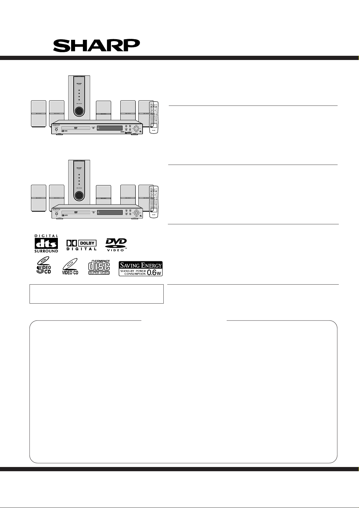
Illustration: HT-CN400DVW
HT-CN400DVW/HT-CN400DVA/HT-CN500DVW/HT-CN500DVA
SERVICE MANUAL
No. XXXXXXXXXXXXX
HOME THEATER WITH DVD
MODEL HT-CN400DVW
ON/
OPEN/
STAND-BY
CLOSE
MUTE
SET UP
DISPLAY
LANGUAGE
TITLE
SUBTITLE
ST/MO
MENU/PBC
ENTER
SLEEP
PROG
SLOW/MEMORY
LISTENING
DIRECT
ANGLE
OPEN/
CLOSE
TITLE
MENU/PBC
PROG
SLOW/MEMORY
LISTENING
9
DIRECT
ANGLE
HT-CN400DVW Home Theater with DVD consisting of HT-CN400DVW
PRESET
TUNING
ADJ/VOL
MODE
321
4
(main unit), CP-CN400WF (front speakers), CP-CN400WC (center
8765
STEP
9
0>10
REPEAT
RETURN
A-B
ZOOM AUDIO
NTSC/PAL
MULTI
speaker), CP-CN400WR (surround speakers) and CP-CN400WSW
(subwoofer).
HOME THEATER WITH DVD
MODEL HT-CN400DVA
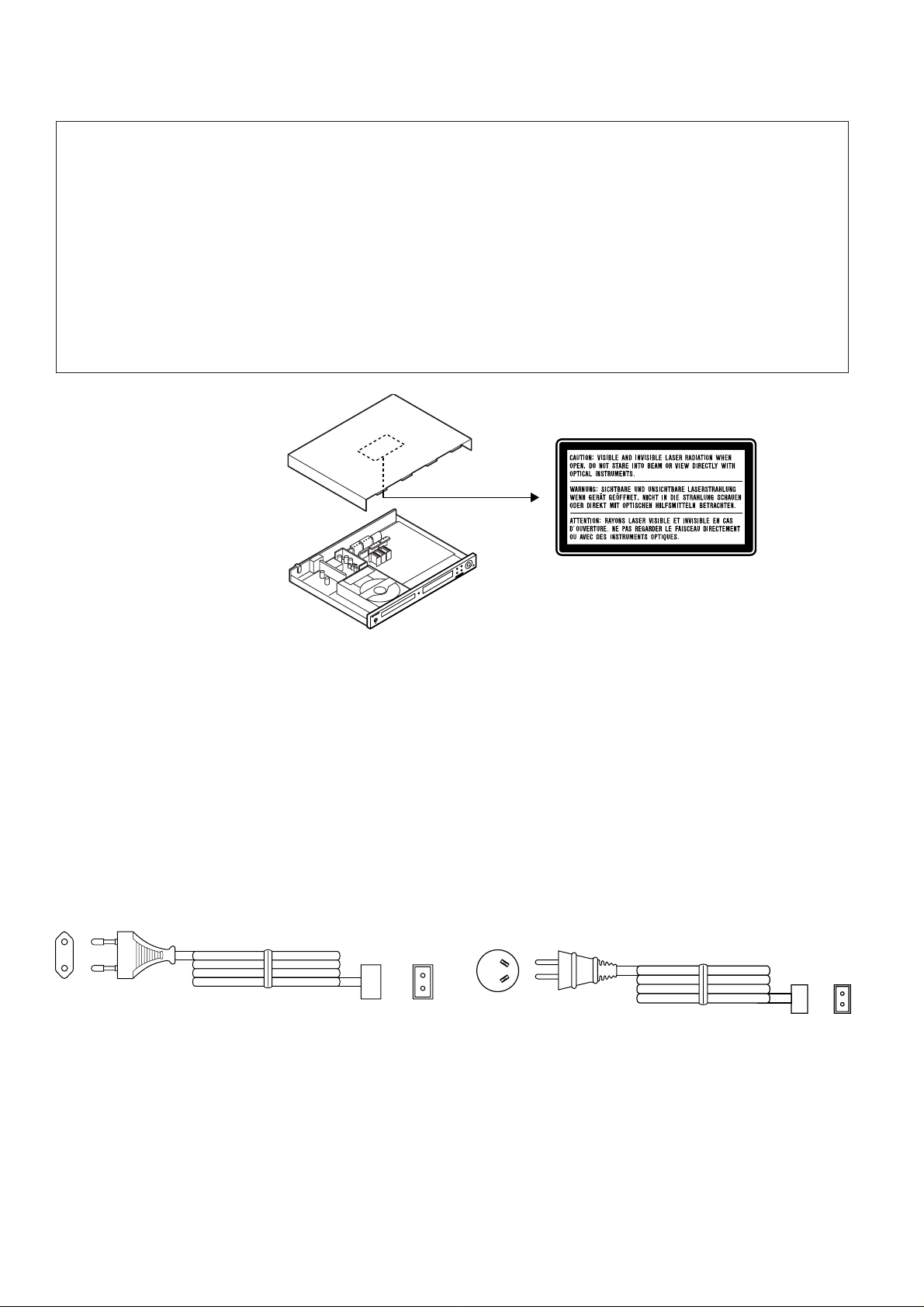
HT-CN400DVA Home Theater with DVD consisting of HT-CN400DVA
(main unit), CP-CN400F (front speakers), CP-CN400C (center speaker),
CP-CN400R (surround speakers) and CP-CN400SW (subwoofer).
ON/
STAND-BY
MUTE
SET UP
DISPLAY
LANGUAGE
SUBTITLE
ST/MO
ENTER
SLEEP
PRESET
TUNING
ADJ/VOL
MODE
321
4
8765
STEP
>
0
10
REPEAT
RETURN
A-B
ZOOM AUDIO
NTSC/PAL
MULTI
HOME THEATER WITH DVD
MODEL HT-CN500DVW
Illustration: HT-CN400DVA
HT-CN500DVW Home Theater with DVD consisting of HT-CN500DVW
(main unit), CP-CN500WF (front speakers), CP-CN500WC (center
speaker), CP-CN500WR (surround speakers) and CP-CN500WSW
(subwoofer).
HOME THEATER WITH DVD
MODEL HT-CN500DVA
• In the interests of user-safety the set should be restored to
its original condition and only parts identical to those specified
be used.
SAFETY PRECAUTION FOR SERVICE MANUAL ........................................................................................................... 2
VOLTAGE SELECTION..................................................................................................................................................... 2
AC POWER SUPPLY CORD............................................................................................................................................. 2
SPECIFICATIONS ............................................................................................................................................................. 3
NAMES OF PARTS ........................................................................................................................................................... 5
DISASSEMBLY.................................................................................................................................................................. 8
ADJUSTMENT ................................................................................................................................................................. 10
SW EXTRA FUNCTION................................................................................................................................................... 10
SOFTWARE UPGRADING & SPECIAL KEY CONTROL ............................................................................................... 11
BLOCK DIAGRAM ........................................................................................................................................................... 12
SCHEMATIC DIAGRAM .................................................................................................................................................. 14
WIRING SIDE OF P.W.BOARD....................................................................................................................................... 26
NOTES ON SCHEMATIC DIAGRAM .............................................................................................................................. 32
TYPES OF TRANSISTOR AND LED............................................................................................................................... 32
VOLTAGE ........................................................................................................................................................................ 33
WAVEFORMS OF DVD CIRCUIT ................................................................................................................................... 37
TROUBLESHOOTING ..................................................................................................................................................... 39
FUNCTION TABLE OF IC................................................................................................................................................ 40
FL DISPLAY..................................................................................................................................................................... 59
REPLACEMENT PARTS LIST/EXPLODED VIEW
HT-CN500DVA Home Theater with DVD consisting of HT-CN500DVA
(main unit), CP-CN500F (front speakers), CP-CN500C (center speaker),
CP-CN500R (surround speakers) and CP-CN500SW (subwoofer).
CONTENTS
Page
SHARP CORPORATION
This document has been published to be used
for after sales service only.
The contents are subject to change without notice.
Page 2
HT-CN400DVW/HT-CN400DVA/HT-CN500DVW/HT-CN500DVA
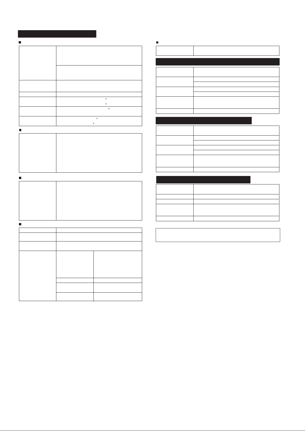
SAFETY PRECAUTION FOR SERVICE MANUAL
WARNINGS
THE AEL (ACCESSIBLE EMISSION LEVEL) OF THE LASER POWER OUTPUT IS LESS THAN CLASS 1 BUT THE LASER
COMPONENT IS CAPABLE OF EMITTING RADIATION EXCEEDING THE LIMIT FOR CLASS 1. THEREFORE IT IS
IMPORTANT THAT THE FOLLOWING PRECAUTIONS ARE OBSERVED DURING SERVICING TO PROTECT YOUR EYES
AGAINST EXPOSURE TO THE LASER BEAM.
1-WHEN THE CABINET IS REMOVED, THE POWER IS TURNED ON WITHOUT A COMPACT DISC IN POSITION AND THE
PICKUP IS ON THE OUTER EDGE THE LASER WILL LIGHT FOR SEVERAL SECONDS TO DETECT A DISC. DO NOT
LOOK INTO THE PICKUP LENS.
2-THE LASER POWER OUTPUT OF THE PICKUP UNIT AND REPLACEMENT SERVICE PARTS ARE ALL FACTORY
PRESET BEFORE SHIPMENT.
DO NOT ATTEMPT TO READJUST THE LASER PICKUP UNIT DURING REPLACEMENT OR SERVICING.
3-UNDER NO CIRCUMSTANCES STARE INTO THE PICKUP LENS AT ANY TIME.
4-CAUTION-USE OF CONTROLS OR ADJUSTMENTS, OR PERFORMANCE OF PROCEDURES OTHER THAN THOSE
SPECIFIED HEREIN MAY RESULT IN HAZARDOUS RADIATION EXPOSURE.
Laser Diode Properties
Material: AlGaAs/AlGalnP
Wavelength: 785 nm/650 nm
Emission Duration: continuous
Laser Output: max. 0.6 mW
VOLTAGE SELECTION
After checking all the connections have been made correctly, plug the AC power lead of this unit into the wall socket.
Wall socket (AC 220-240 V, 50/60 Hz).
AC POWER SUPPLY CORD
92L2559K022G24
92LVPE16253010
– 2 –
Page 3
FOR A COMPLETE DESCRIPTION OF THE OPERATION OF THIS UNIT, PLEASE REFER
TO THE OPERATION MANUAL.
HT-CN400DVW/HT-CN500DVW
HT-CN400DVW/HT-CN400DVA/HT-CN500DVW/HT-CN500DVA
SPECIFICATIONS
General
Power source AC 220 - 240 V, 50/60 Hz
Power consumption HT-CN400DVW:
Dimensions Width: 430 mm (16-7/8")
Weight 4.2 kg (9.3 lbs.)
Audio input terminals Analogue input (IN 1): RCA type 1 pair (L/R)
Audio output
terminals
Video output
terminals
Amplifier (HT-CN400DVW)
Output power Front speakers:
Amplifier (HT-CN500DVW)
Output power Front speakers:
Power on: 88 W
Power stand-by: 0.6 W
HT-CN500DVW:
Power on: 105 W
Power stand-by: 0.6 W
Height: 53 mm (2-1/8")
Depth: 337 mm (13-1/4")
Analogue input (IN 2): RCA type 1 pair (L/R)
Analogue output (OUT): RCA type 1 pair (L/R)
S-video output: S-terminal 1
Video output: RCA type 1
RMS: 60 W (30 W + 30 W) (10 % T.H.D., 1 kHz)
Centre speaker:
RMS: 30 W (10 % T.H.D., 1 kHz)
Surround speakers:
RMS: 60 W (30 W + 30 W) (10 % T.H.D., 1 kHz)
Subwoofer:
RMS: 50 W (10 % T.H.D., 100 Hz)
RMS: 100 W (50 W + 50 W) (10 % T.H.D., 1 kHz)
Centre speaker:
RMS: 50 W (10 % T.H.D., 1 kHz)
Surround speakers:
RMS: 100 W (50 W + 50 W) (10 % T.H.D., 1 kHz)
Subwoofer:
RMS: 50 W (10 % T.H.D., 100 Hz)
Tuner
Frequency range FM: 88 - 108 MHz
AM: 531 - 1,620 kHz
CP-CN400WF/CP-CN500WF/CP-CN400WC/CP-CN500WC
Type Full range speaker system (magnetic shield)
Maximum input power HT-CN400DVW: 45 W
Impedance HT-CN400DVW: 8 ohms
Dimensions Width: 94 mm (3-3/4")
Weight 0.6 kg (1.3 lbs.)/each
8 cm (3-1/8") speaker
HT-CN500DVW: 60 W
HT-CN500DVW: 6 ohms
Height: 169 mm (6-5/8")
Depth: 97 mm (3-7/8")
CP-CN400WR/CP-CN500WR
Type Full range speaker system
Maximum input power HT-CN400DVW: 45 W
Impedance HT-CN400DVW: 8 ohms
Dimensions Width: 94 mm (3-3/4")
Weight 0.6 kg (1.3 lbs.)/each
8 cm (3-1/8") speaker
HT-CN500DVW: 60 W
HT-CN500DVW: 6 ohms
Height: 169 mm (6-5/8")
Depth: 97 mm (3-7/8")
CP-CN400WSW/CP-CN500WSW
Type Sub-woofer system
Maximum input power 75 W
Impedance 6 ohms
Dimensions Width: 135 mm (5-5/16")
Weight 5.3 kg (11.7 lbs.)
12 cm (4-3/4") subwoofer
Height: 338 mm (13-5/16")
Depth: 375 mm (14-3/4")
DVD player
Signal system PAL/NTSC colour
Supported disc types DVD (with the same region number on the back of the unit
Video signal Horizontal resolution: 500 lines
Audio signal Frequency character-
or ALL), SVCD, VCD, audio CD, CD-R, CD-RW, MP3
S/N ratio: 70 dB
istics
S/N ratio CD: 94 dB (1 kHz)
Dynamic range Linear PCM DVD: 95 dB
Total harmonic distortion ratio
Linear PCM DVD:
20 Hz to 20 kHz
(sampling rate: 48 kHz)
20 Hz to 20 kHz
(sampling rate: 96 kHz)
CD: 20 Hz to 20 kHz
CD: 94 dB
0.01 % maximum
Specifications for this model are subject to change without
prior notice.
– 3 –
Page 4
HT-CN400DVW/HT-CN400DVA/HT-CN500DVW/HT-CN500DVA
HT-CN400DVA/HT-CN500DVA
General
Power source AC 220 - 240 V, 50/60 Hz
Power consumption HT-CN400DVA:
Dimensions Width: 430 mm (16-7/8")
Weight 4.2 kg (9.3 lbs.)
Audio input terminals Analogue input (IN 1): RCA type 1 pair (L/R)
Audio output
terminals
Video output
terminals
Amplifier (HT-CN400DVA)
Output power Front speakers:
Amplifier (HT-CN500DVA)
Output power Front speakers:
DVD player
Signal system PAL/NTSC colour
Supported disc types DVD (Region number 4, ALL), SVCD, VCD, audio CD,
Video signal Horizontal resolution: 500 lines
Audio signal Frequency character-
Power on: 88 W
Power stand-by: 0.6 W
HT-CN500DVA:
Power on: 105 W
Power stand-by: 0.6 W
Height: 53 mm (2-1/8")
Depth: 337 mm (13-1/4")
Analogue input (IN 2): RCA type 1 pair (L/R)
Analogue output (OUT): RCA type 1 pair (L /R)
Headphones: 16 - 50 ohms (recommended: 32 ohms)
S-video output: S-terminal 1
Video output: RCA type 1
RMS: 60 W (30 W + 30 W) (10 % T.H.D., 1 kHz)
Centre speaker:
RMS: 30 W (10 % T.H.D., 1 kHz)
Surround speakers:
RMS: 60 W (30 W + 30 W) (10 % T.H.D., 1 kHz)
Subwoofer:
RMS: 50 W (10 % T.H.D., 100 Hz)
RMS: 100 W (50 W + 50 W) (10 % T.H.D., 1 kHz)
Centre speaker:
RMS: 50 W (10 % T.H.D., 1 kHz)
Surround speakers:
RMS: 100 W (50 W + 50 W) (10 % T.H.D., 1 kHz)
Subwoofer:
RMS: 50 W (10 % T.H.D., 100 Hz)
CD-R, CD-RW, MP3
S/N ratio: 70 dB
istics
S/N ratio CD: 94 dB (1 kHz)
Dynamic range Linear PCM DVD: 95 dB
Total harmonic distortion ratio
Linear PCM DVD:
20 Hz to 20 kHz
(sampling rate: 48 kHz)
20 Hz to 20 kHz
(sampling rate: 96 kHz)
CD: 20 Hz to 20 kHz
CD: 94 dB
0.01 % maximum
Tuner
Frequency range FM: 87.5 - 108 MHz
CP-CN400F/CP-CN500F/CP-CN400C/CP-CN500C
Type Full range speaker system (magnetic shield)
Maximum input power HT-CN400DVA: 45 W
Impedance HT-CN400DVA: 8 ohms
Dimensions Width: 94 mm (3-3/4")
Weight 0.6 kg (1.3 lbs.)/each
CP-CN400R/CP-CN500R
Type Full range speaker system
Maximum input power HT-CN400DVA: 45 W
Impedance HT-CN400DVA: 8 ohms
Dimensions Width: 94 mm (3-3/4")
Weight 0.6 kg (1.3 lbs.)/each
CP-CN400SW/CP-CN500SW
Type Sub-woofer system
Maximum input power 75 W
Impedance 6 ohms
Dimensions Width: 135 mm (5-5/16")
Weight 5.3 kg (11.7 lbs.)
Specifications for this model are subject to change without
prior notice.
AM: 522 - 1,620 kHz
8 cm (3-1/8") speaker
HT-CN500DVA: 60 W
HT-CN500DVA: 6 ohms
Height: 169 mm (6-5/8")
Depth: 97 mm (3-7/8")
8 cm (3-1/8") speaker
HT-CN500DVA: 60 W
HT-CN500DVA: 6 ohms
Height: 169 mm (6-5/8")
Depth: 97 mm (3-7/8")
12 cm (4-3/4") subwoofer
Height: 338 mm (13-5/16")
Depth: 375 mm (14-3/4")
– 4 –
Page 5
HT-CN400DVW/HT-CN500DVW
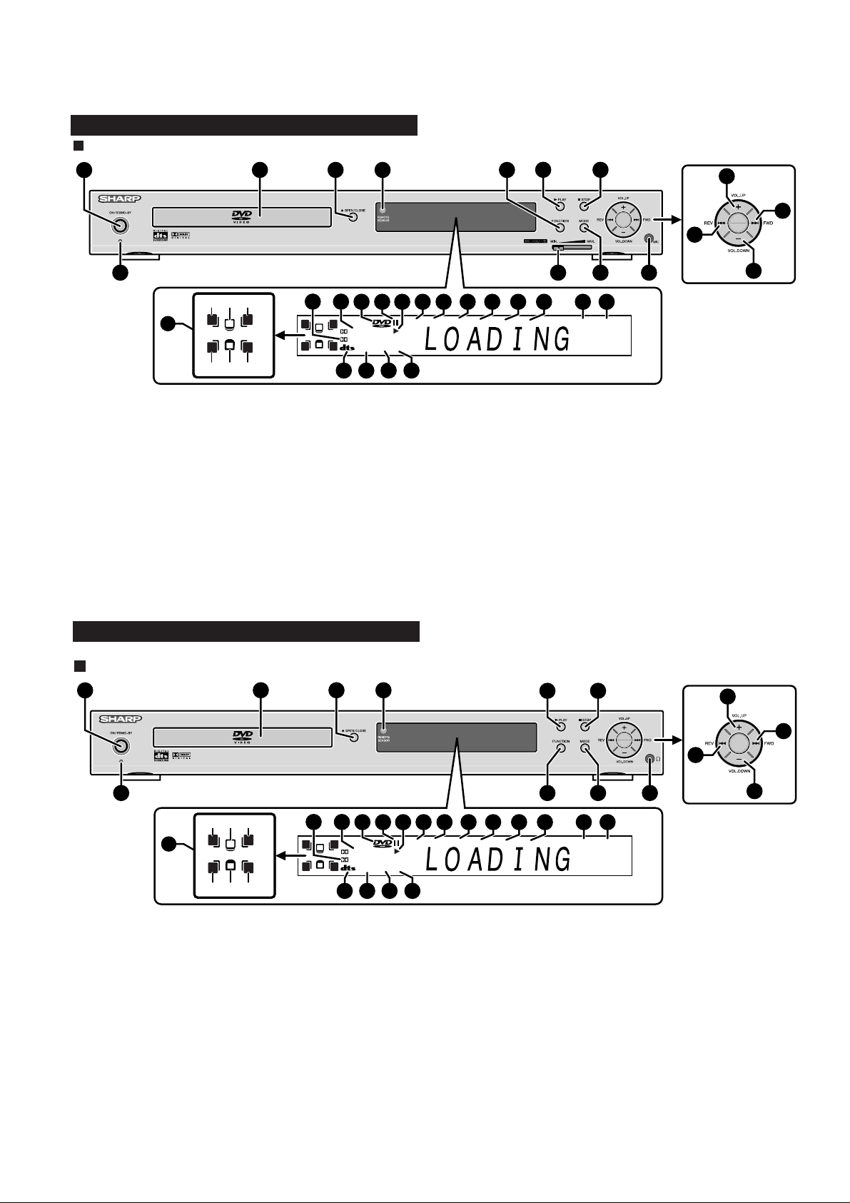
Main unit (front panel)
1
HT-CN400DVW/HT-CN400DVA/HT-CN500DVW/HT-CN500DVA
NAMES OF P ARTS
2
3
4 5
6
7
13
14
12
8
(1)
(3)(2)
RL
15
C
S
RSLS
(4) (6)(5)
1. On/Stand-by Button
2. Disc Tray
3. Disc Tray Open/Close Button
4. Remote Sensor
5. Function Button
6. Play or Pause Button
7. Stop Button
8. Power Stand-by Indicator
9. Microphone Volume Control
10. Speaker Level Mode Button
11. Microphone Socket
12. Chapter (track) Skip Down or Tuning Down Button
13. Volume Up and Down or Speaker Level Adjust Buttons
14. Chapter (track) Skip Up or Tuning Up Button
15. Speaker Indicators
(1) Left Front Speaker Indicator (4) Left Surround Speaker Indicator
(2) Centre Speaker Indicator (5) Subwoofer Indicator
(3) Right Front Speaker Indicator (6) Right Surround Speaker Indicator
16 17
RL
C
S
RSLS
29 30 31 32
DIGITAL
Pro Logic
HT-CN400DVA/HT-CN500DVA
Main unit (front panel)
1
2
3
9
232218 19 20 21
REPEAT1SLEEPPROGCHPPRESETTRKTITLE
1110
2827262524
A-B
13
KHz
CD MP3STEREO V
16. Dolby Pro Logic Indicator
17. Dolby Digital Signal Indicator
18. DVD Indicator
19. Pause Indicator
20. Play Indicator
21. Title Indicator
22. Track Indicator
23. Tuner Preset Indicator
24. Chapter Indicator
25. Programme Indicator
26. Sleep Indicator
27. Repeat Indicator
28. A - B Repeat Indicator
29. DTS Signal Indicator
30. Stereo (2-ch) or FM Stereo Receiving Indicator
31. SVCD/VCD/CD Indicator
32. MP3 or JPEG Indicator
4
5
MHz
6
12
7
(1)
(3)(2)
RL
14
C
S
RSLS
(4) (6)(5)
1. On/Stand-by Button
2. Disc Tra y
3. VDisc Tray Open/Close Button
4. Remote Sensor
5. Play or Pause Button
6. Stop Button
7. Power Stand-by Indicator
8. Function Button
9. Speaker Level Mode Button
10. Headphone Socket
11. Chapter (track) Skip Down or Tuning Down Button
12. Volume Up and Down or Speaker Level Adjust Buttons
13. Chapter (track) Skip Up or Tuning Up Button
14. Speaker Indicators
(1) Left Front Speaker Indicator (4) Left Surround Speaker Indicator
(2) Centre Speaker Indicator
(3) Right Front Speaker Indicator (6) Right Surround Speaker Indicator
(5) Subwoofer Indicator
15 16
RL
C
S
RSLS
28 29 30 31
DIGITAL
Pro Logic
13
11
8 9
222117 18 19 20
REPEAT1SLEEPPROGCHPPRESETTRKTITLE
10
2726252423
A-B
KHz
CD MP3STEREO V
15. Dolby Pro Logic Indicator
16. Dolby Digital Signal Indicator
17. DVD Indicator
18. Pause Indicator
19. Play Indicator
20. Title Indicator
21. Track Indicator
22. Tuner Preset Indicator
23. Chapter Indicator
24. Programme Indicator
25. Sleep Indicator
26. Repeat Indicator
27. A - B Repeat Indicator
28. DTS Signal Indicator
29. Stereo (2-ch) or FM Stereo Receiving Indicator
30. SVCD/VCD/CD Indicator
31. MP3 or JPEG Indicator
MHz
12
– 5 –
Page 6
HT-CN400DVW/HT-CN400DVA/HT-CN500DVW/HT-CN500DVA
HT-CN400DVW/HT-CN400DVA/HT-CN500DVW/HT-CN500DVA
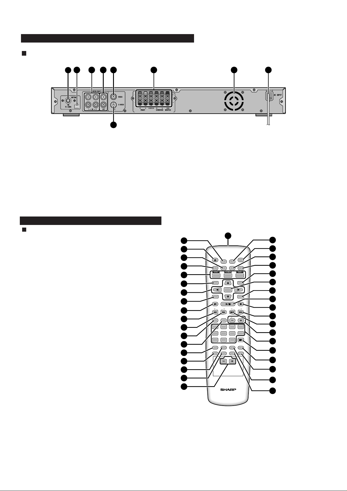
Main unit (rear panel)
2 394 5 86 7
1
1. FM 75 Ohms Aerial Socket
2. AM Loop Aerial Socket
3. Audio Input Sockets 1/2
4. Audio Output Sockets
5. Video Output Socket
6. Speaker Terminals
7. Cooling Fan
8. AC Power Lead
9. S-video Output Socket
HT-CN400DVW/HT-CN500DVW
Remote control
1. Remote Control Transmitter
2. Set Up Menu Button
3. Disc Tray Open/Close Button
4. Subtitle Select Button
5. Title Select Button
6. DVD/Tuner/Auxiliary Input Select Buttons
7. Menu/Playback Control On/Off Button
8. Cursor Buttons
9. Programme Button
10. Slow-motion or Preset Memory Button
11. Fast Reverse or Preset Down Button
12. Fast Forward or Preset Up Button
13. Surround/Stereo (2-ch) Listening Mode Button
14. Speaker Level Mode Button
15. Direct Button
16. Angle Select Button
17. Return Button
18. Zoom Button
19. Echo Level Up and Down Buttons
20. Mute Button
21. On/Stand-by Button
22. Language Select Button
23. Display Button
24. FM Stereo/Mono Select Button
25. Enter Button
26. Sleep Button
27. Play or Pause Button
28. Stop Button
29. Chapter (track) Skip Up or Tuning Up Button
30. Chapter (track) Skip Down or Tuning Down Button
31. Volume Up and Down or Speaker Level Adjust Buttons
32. Direct Number Buttons
33. Frame Advance Button
34. A - B Repeat Button
35. NTSC/PAL Select Button
36. Repeat Play Button
37. Audio Select Button
10
12
13
14
15
16
17
18
19
11
2
1
3
OPEN/
CLOSE
TITLE
MENU/PBC
SET UP
SUBTITLE
4
5
6
MUTE
LANGUAGE
ON/
STAND-BY
DISPLAY
ST/MO
7
ENTER
8
9
PROG
SLOW/MEMORY
PRESET
LISTENING
9
DIRECT
ANGLE
RETURN
MODE
0>10
REPEAT
ZOOM AUDIO
ECHO
TUNING
ADJ/VOL
321
SLEEP
4
8765
STEP
A-B
NTSC/PAL
MULTI
20
21
22
23
24
25
26
27
28
29
30
31
32
33
34
35
36
37
– 6 –
Page 7
HT-CN400DVW/HT-CN400DVA/HT-CN500DVW/HT-CN500DVA
HT-CN400DVA/HT-CN500DVA
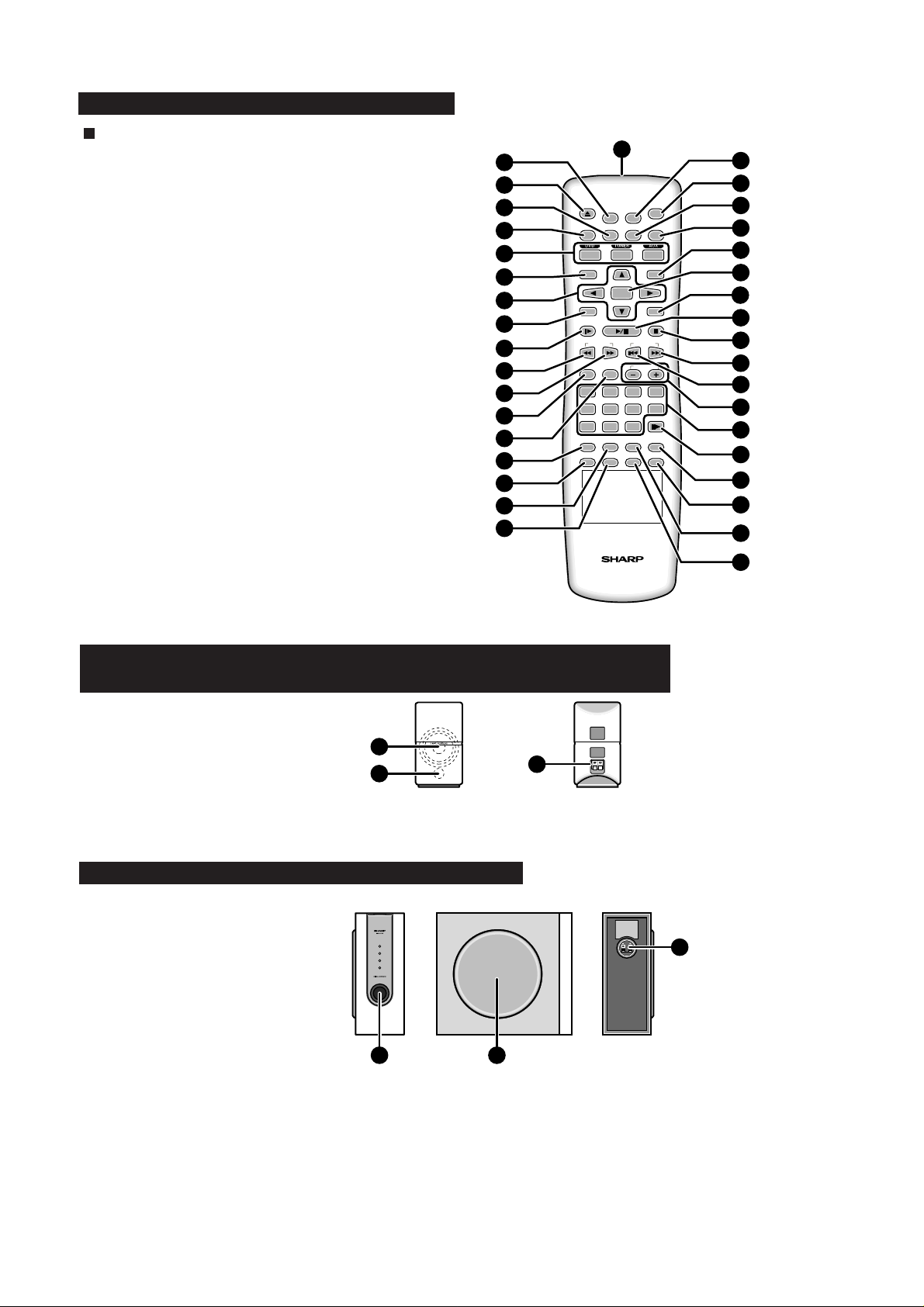
Remote control
1. Remote Control Transmitter
2. Set Up Menu Button
3. Disc Tray Open/Close Button
4. Subtitle Select Button
5. Title Select Button
6. DVD/Tuner/Auxiliary Input Select Buttons
7. Menu/Playback Control On/Off Button
8. Cursor Buttons
9. Programme Button
10. Slow-motion or Preset Memory Button
11. Fast Reverse or Preset Down Button
12. Fast Forward or Preset Up Button
13. Surround/Stereo (2-ch) Listening Mode Button
14. Speaker Level Mode Button
15. Direct Button
16. Angle Select Button
17. Return Button
18. Zoom Button
19. Mute Button
20. On/Stand-by Button
21. Language Select Button
22. Display Button
23. FM Stereo/Mono Select Button
24. Enter Button
25. Sleep Button
26. Play or Pause Button
27. Stop Button
28. Chapter (track) Skip Up or Tuning Up Button
29. Chapter (track) Skip Down or Tuning Down Button
30. Volume Up and Down or Speaker Level Adjust Buttons
31. Direct Number Buttons
32. Frame Advance Button
33. A - B Repeat Button
34. NTSC/PAL Select Button
35. Repeat Play Button
36. Audio Select Button
10
12
13
14
15
16
17
18
11
2
1
3
OPEN/
CLOSE
TITLE
MENU/PBC
SET UP
SUBTITLE
4
5
6
MUTE
LANGUAGE
ON/
STAND-BY
DISPLAY
ST/MO
7
ENTER
MODE
>
0
REPEAT
ZOOM AUDIO
TUNING
ADJ/VOL
321
10
SLEEP
4
8765
STEP
A-B
NTSC/PAL
8
9
PROG
SLOW/MEMORY
PRESET
LISTENING
9
DIRECT
ANGLE
RETURN
19
20
21
22
23
24
25
26
27
28
29
30
31
32
33
34
35
36
CP-CN400WF/CP-CN400WC/CP-CN400WR/CP-CN400F/CP-CN400C/CP-CN400R/
CP-CN500WF/CP-CN500WC/CP-CN500WR/CP-CN500F/CP-CN500C/CP-CN500R
1. Speaker
2. Bass Reflex Duct
3. Speaker Terminals
1
2
3
CP-CN400WSW/CP-CN400SW/CP-CN500WSW/CP-CN500SW
1. Bass Reflex Duct
2. Woofer
3. Speaker Terminals
21
3
– 7 –
Page 8
HT-CN400DVW/HT-CN400DVA/HT-CN500DVW/HT-CN500DVA
(B1)x4
ø3x6mm
(B1)x7
ø3x8mm
Rear Panel
Fan Motor
Main PWB
Front
Panel
Lug Wire
(B2)x1
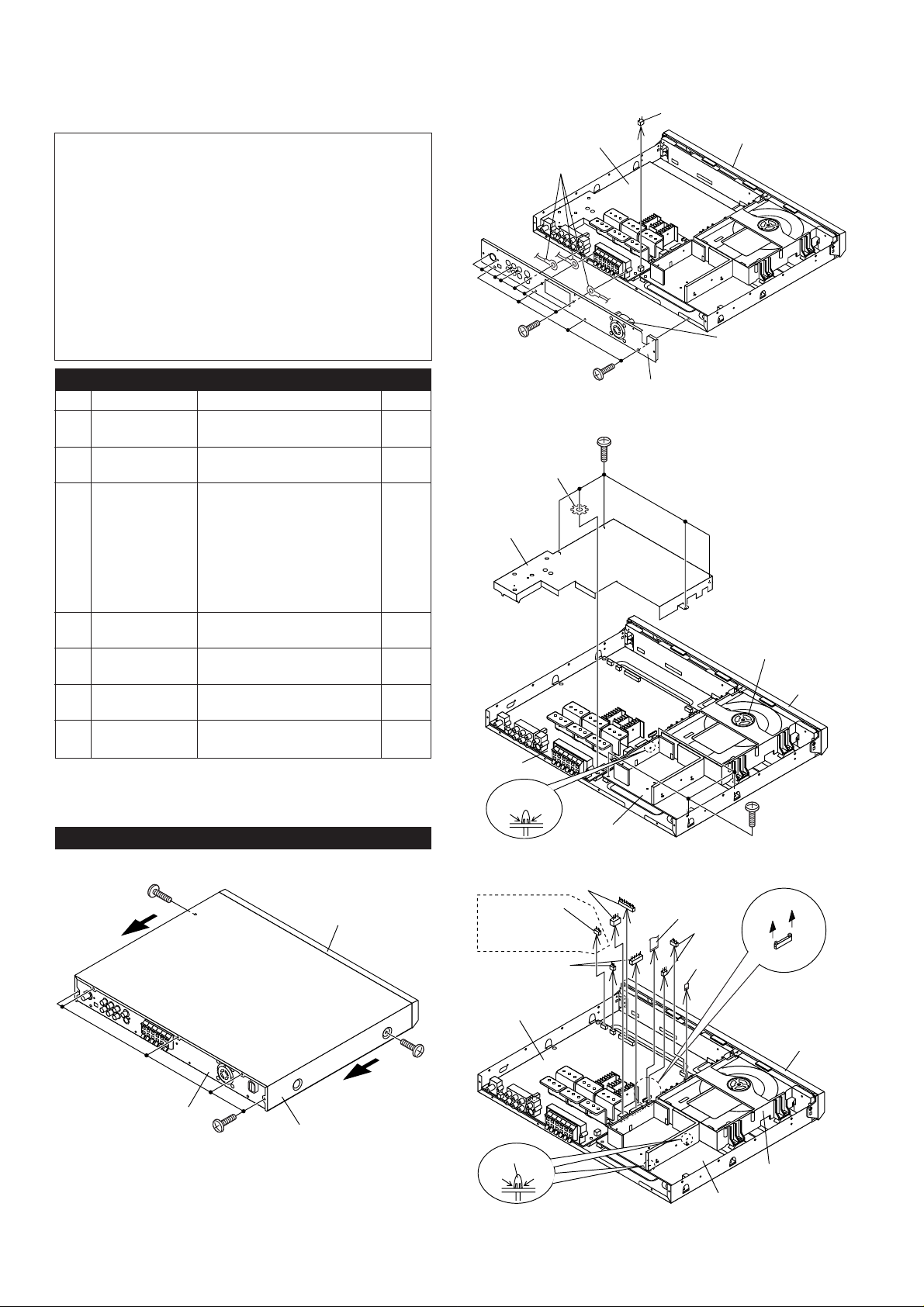
DISASSEMBLY
Caution on Disassembly
Follow the below-mentioned notes when disassembling
the unit and reassembling it, to keep it safe and ensure
excellent performance:
1. Take dvd disc out of the unit.
2. Be sure to remove the power supply plug from the wall
outlet before starting to disassemble the unit.
3. Take off nylon bands or wire holders where they need to
be removed when disassembling the unit. After servicing
the unit, be sure to rearrange the leads where they were
before disassembling.
4. Take sufficient care on static electricity of integrated
circuits and other circuits when servicing.
HT-CN400DVW/HT-CN400DVA/HT-CN500DVW/HT-CN500DVA
STEP REMOVAL PROCEDURE FIGURE
1 Top Cabinet 1. Screw ...................... (A1) x7 8-1
2. Pull to the arrow direction.
2 Rear Panel with 1. Screw .................... (B1) x11 8-2
Fan Motor 2. Socket ..................... (B2) x1
3 Main PWB 1. Screw ...................... (C1) x5 8-3
2. PWB Shield Cover .. (C2) x1
3. Socket ..................... (C3) x6 8-4
4. Socket ..................... (C4) x1
(HT-CN400DVW/
HT-CN500DVW Only)
5. Flat Cable ............... (C5) x2
6. PWB Holder ........... (C6) x1 8-3
4 Power PWB 1. Screw ...................... (D1) x4 8-3
4. PWB Holder ........... (D1) x2 8-4
5 Front Panel 1. Screw ...................... (E1) x8 9-1
2. Hook........................ (E2) x3
6 Display/Switch 1. Screw .......................(F1) x9 9-2
PWB
7 Earphones 1. Screw ...................... (G1) x1 9-2
PWB 2. Bracket.................... (G2) x1
HT-CN400DVW/HT-CN400DVA/HT-CN500DVW/HT-CN500DVA
(A1)x1
ø3x6mm
Front
Panel
Pull
(HT-CN400DVW/
HT-CN500DVW
Only)
Washer
(C2)x1
Main PWB
(C6)x4
PushPush
(C3)x2
(C4)x1
(C3)x2
Figure 8-2
(C1)x5
ø3x8mm
Power PWB
Figure 8-3
(C5)x1
(C3)x2
(C5)x1
Loading Tray
Mechanism
Front
Panel
(D1)x4
ø3x8mm
Rear Panel
(A1)x5
ø3x6mm
Figure 8-1
Pull
Top Cabinet
(A1)x1
ø3x6mm
– 8 –
Main PWB
(D2)x2
PushPush
Figure 8-4
Loading
Tray Mechanism
Power PWB
Front
Panel
Page 9

HT-CN400DVW/HT-CN400DVA/HT-CN500DVW/HT-CN500DVA
(B1)x4
ø3x8mm
Speaker
Front Panel
(A2)x4
ø3.5x14mm
(A1)x1
Speaker Box
Speaker
Lug Wire
(E1)x3
ø3x6mm
(G1)x1
ø3x8mm
(E2)x1
(E1)x1
ø3x6mm
Loading Tray
Mechanism
(G2)x1
Display PWB
(F1)x6
ø3x8mm
Figure 9-1
Earphones PWB
(F1)x3
ø3x8mm
Figure 9-2
(E2)x1
(E1)x3
ø3x8mm
Front
Panel
Front
Panel
(E1)x1
ø3x6mm
(E2)x1
Switch PWB
Figure 9-4
CP-CN400WSW/CP-CN400SW/
CP-CN500WSW/CP-CN500SW
STEP REMOVAL PROCEDURE FIGURE
1 Speaker 1. Net Frame Ass'y .... (A1) x1 9-5
2. Screw ..................... (A2) x4
CP-CN400WF/CP-CN400WC/CP-CN400WR/CP-CN400AF/
CP-CN400C/CP-CN400R/CP-CN500WF/CP-CN500WC/
CP-CN500WR/CP-CN500F/CP-CN500C/CP-CN500R
STEP
REMOVAL PROCEDURE
1 Front panel 1. Net Frame Ass'y .... (A1) x1 9-3
2. Screw ..................... (A2) x4
2 Speaker 1. Screw ..................... (B1) x4 9-4
(A1)x1
Front Panel
(A2)x4
ø3.5x8mm
FIGURE
Speaker Box
Figure 9-3
Figure 9-5
– 9 –
Page 10

HT-CN400DVW/HT-CN400DVA/HT-CN500DVW/HT-CN500DVA
JK001
FM ANTENNA
1
2
AM LOOP
ANTENNA
MAIN PWB
AM IF
AM Band
Coverage fL
FM IF
AM Band
Coverage fH
AM
Tracking fL
AM
Tracking fH
IC001
1
15 16
30
17
ADJUSTMENT
TUNER SECTION
fL: Low-range frequency
fH: High-range frequency
••
•
AM IF/RF
••
Signal generator: 400 Hz, 30%, AM modulated
Test Stage Frequency Frequency
Display
AM IF 450 kHz 1,620 kHz T008 *1
AM Band — 522 kHz (fL): T003 *2
Coverage (fH):TC002
AM Tracking 990 kHz 990 kHz (fL): T002 *1
*1. Input: Antenna
*2. Input: Antenna Output: IC001 Pin17(L) or Pin16(R)
• FM IF
Notes:
1: Description of the "FM IF Adjustment" is not carried on this
Manual. It is because the IF coil in the FM front end section
has been best adjusted in the factory so that its further
adjustment is not needed at the field. When replacing the
FM front end assembly, no adjustment is needed either.
2: The parts in the FM front end section are prepared in a
complete unit, so you can't obtain each part individually.
Setting/
Adjusting
Parts
(fH): TC001
Instrument
Connection
Figure 10 TUNER ADJUSTMENT POINTS
••
•
FM Detection
••
Signal generator: 10.7 MHz, FM sweep generator
Test Stage Frequency Frequency
FM IF 10.7 MHz 98.0 MHz
Display
Setting/
Adjusting
Parts
T007 (Tuner
core of Pin 1 of
T007 fully EF001
counterclockwise)
Instrument
Connection
Input:
1. How to show Version number.
SW EXTRA FUNCTION
A. Door Open,
B. Press and hold R/C "Volume up" Button;
C. Press R/C "Zoom" button continue,
D. OSD show version number,
VER
xxxx x PAL xx x xx
Month and day version TV TYPE Tuner area region code LANGUAGE
The first
xxxx stand for month and day, the second x stand for version sequence, the third x stand for TV system, the forth
xx for tuner area, the fifth x stand for region code. The sixth code xx stand for language.
2. How to adjust TUNER AREA.
A. Door Open
B. Press and hold R/C "Volume up" button;
C. Press R/C "Subtitle" button continue;
D. OSD show "Tuner Area: xx
Press Down button to select
Press OK button to confirm"
E. Then use R/C
to select tuner area you want (EUR USA cyclically), then press " OK" to confirm,
F. If OK button is pressed in five seconds, OSD will show "Tuner Area Change"; If you didn't press it in five seconds, the system
will remain original status.
3. How to select region code;
A. DVD door open
B. Press and hold R/C "Volume up" button;
C. Press R/C "Language" button;
D. TV shows region code
E. Cyclically press Up/Down button to select region code 0 1 2 3 4 5 6 0
F. Press " Enter" button to save the region code. If no press "Enter" button in five seconds, then the region code remain original
status.
4. How to select OSD Language Sequency,
A. Door close and no disc,
B. Press and hold R/C "Volume up" button;
C. Then Press R/C "Subtitle" button;
D. OSD show last setting "OSD language", (English France German Italian Spanish).
E. Then use
F. For example: default language is English, you select English and press Enter button, then its sequence is change to
(English France German Italian Spanish)
button to select language that you want and its sequence.
– 10 –
Page 11

HT-CN400DVW/HT-CN400DVA/HT-CN500DVW/HT-CN500DVA
SOFTWARE UPGRADING & SPECIAL KEY CONTROL
1. Software Upgrading
a) Burn the software "bank30.rom" in CD-R/CD-RW (lower burning speed is recommended).
b) Load CD-R/CD-RW in DVD receiver.
c) After finished loading, VFD will show "Read" and OSD will display "Reading".
d) After reading, system will start upgrading software, VFD will show "Update" and OSD will
display "Erase" then "Writing".
* If fail to upgrade, OSD will display "Checksum error". Turn off/on power and try upgrading
again. If still fail, re-burn CD-R/CD-RW.
e) After finished "Writing", VFD and OSD will display "Done" then tray will open automatically.
* If the tray did not open automatically, just proceed to next step (f).
f) Unplug and plug in AC power cord or turn off and on main power supply.
g) Turn on power and confirm the software version.
h) Defaults the reset => Power on the set, press “set up” button at remote control, SETUP menu will display at TV screen,
go to enter PREFERENCES. At Preferences Page, go to Defaults-Reset and enter the Reset.
Caution : DO NOT disturb or cut off power supply during software upgrading, it will cause the data
lost. Hence the flash IC have to be burned software again.
2. Special Key Control
a) Software version i) On Tray open condition.
ii) Press and hold remote controller key "Volume up" for 2 seconds.
iii) Release "Volume up"key then press "Zoom" key.
iv) OSD will display " VER xxxx x yy z ".
Where xxxx xis Version number
yy is Tuner area
z is Region code
b) Tuner Area i) On Tray open condition.
ii) Press and hold remote controller key "Volume up" for 2 seconds.
iii) Release "Volume up"key then press "Subtitle" key.
iv) OSD will display "Tuner area".
v) Follow OSD instruction to change the tuner area
vi) After tuner area was changed, the preset station will be initialized at default station.
c) Region Code i) On Tray open condition.
ii) Press and hold remote controller key "Volume up" for 2 seconds.
iii) Release "Volume up"key then press "Language" key.
iv) OSD will display "Region Code".
v) Follow OSD instruction to change the region code.
d) OSD Language i) On No disc condition.
ii) Press and hold remote controller key "Volume up" for 2 seconds.
iii) Release "Volume up"key then press "Subtitle" key.
iv) OSD will display "OSD Language".
v) Follow OSD instruction to change the OSD language.
– 11 –
Page 12

HT-CN400DVW/HT-CN400DVA/HT-CN500DVW/HT-CN500DVA
E
D
µ
T
M
D
D
M
W
P
DVD MECHANISM UNIT
MAIN BOARD
LOADER
IC801
DVD MOTOR
Drive IC
LA6560
IC802
DVD Servo RF IC
LA9703W
SDRAM
256K
DVD Servo Control
74LS157
Digital Audio Select
IC803
LC78663W
I/O PORT
74HC32
74HC14
EXPAND
I/O PORT
74LS374*3
DATA
FLASH
8M
2CH AUDIO A/D
AUX1
AUX2
FM
AM
TUNER
LA1837
PLL: LA72131
TUNER BOARD
IC110
2CH AUDIO A/D
AUDIO
INPUT
SELECT
CD4052
Figure 12 BLOCK DIAGRAM (1/2)
– 12 –
AUDIO BUFFER
JRC4558
WM8772
6CH AUDIO D/A
FLFRCSLSR
FILTER
JRC4558*3
C
SL
FR
SR
SUB
SUB
FL
Page 13

HT-CN400DVW/HT-CN400DVA/HT-CN500DVW/HT-CN500DVA
FLASH
8M
4*16M 24C02
IC106
ESS6028
MPEG II Decoder
DTS Decoder
DOLBY DIGITAL Decoder
DOLBY PROG LOGIC Decoder
WMA Decoder
MP3 Decoder
TV ENCODE
Progressive Scan
µ-com
KEY ARRAY VFD
EEPROMSDRAM
PANNEL BOARD
PIC16C54C
PT6311
POWER BOARD
POWER BOARD
PANNEL BOARD
S-VIDEO
CVBS
VIDEO FILTER
OPTICAL
DIGITAL OUT
COAXIAL
L
R
FL
FR
C
SL
SR
SUB
MIC A/D
WM8739
Digital Audio Processo
Bass and Treble Control
6CH Volume Control
Bass management
DX-8000
PHONE VOLUME
PT2259
DOWNMIXING
JRC4558
MICAMP
JRC4558
FL
POWER
AMPLIFIER
DDX-2100*2
DDX-2100*3
L
R
LT=L-0.707SL-0.707SR+0.707C
RT=R+0.707SL+0.707SR+0.707C
FR
C
SL
SR
SUB
PHONEAMP.
TP5228
FILTER
Microphone
INPUT
FL
FR
C
SL
SR
SUB
SPEAKER OUT
PHONE
OUTPUT
LT
RT
LINE OUT
FR
FL
C
SL
SR
SUB
Figure 13 BLOCK DIAGRAM (2/2)
– 13 –
Page 14
HT-CN400DVW/HT-CN400DVA/HT-CN500DVW/HT-CN500DVA
R
R
R
1
5
7
A
A
22PF
R
R
W
V
2
3
.
SITUATION :
R001
C058
15PF
R053
EF001
GNDVTB+
GNDVTB+
100K
R002
5P
C005
C007
0.1
R052
1K
C064
47UF
0.1
C065
C066
0.001
XL001
100K
C057
15PF
IC105
RESET
40
39
38
37
36
35
34
33
32
31
30
29
28
27
26
25
24
23
22
21
D0
D1
D2
D3
D4
D5
IC102
D6
D7
OE
CLK
D0Q0
D1Q1
D2Q2
D3Q3
D4Q4
D5Q5
D6Q6
IC103
D7Q7
OE
CLK
1Y
2Y
3Y
4Y
0.1
0.022
C016
C004
TC001
(22P)
C006
0.1
R058
10 OHM
R009
22K
3.3K
R051
201
XOUT
XINCEDICLDO
4.5 MHz
2345678
TU-CE
A17
A19
A10
D7
D6
D5
D4
D3
D2
D1
D0
LOE#
LCS3#
A0
3
4
7
8
13
14
17
18
1
11
3
4
7
8
13
14
17
18
1
11
DMDR
4
DMCLK
7
DMFS
9
12
R815
FWD S-GND
HT-CN400DVW/
HT-CN500DVW ONLY
IF/O
OSC
IF/O
OSC
5PF
C003
R008
100
Q001
SK192A
G
VD001
LSV149B
R003
100K
1K
R004
C062
3.3UF
3.3K
1K
R050
R049
PD
AIN
VSS
VDD
AOUT
BO1
SDB
TU-DI
TU-CL
YU-DO
TU5V
VC33
C107
0.1
IMP809SEUR
VC33
D0
D1
D2
D3
D4
D5
D6
D7
D8
D9
D10
D11
LCS2#
D15
D14
D13
D12
R150
R151
R152
VCC
C106
0.1
22K
R061
560
D
FMIN
BO2
TU12V
IC105
C103
VCC
R010
270K
C017
0.022
Q002
2SC1009A
R011
S
R005
100 OHM
R006
100 OHM
C009
C012
0.022
47UF
C061
47UF
R057
4.7K
C059
100P
111213141516171819
IO2
4.7K
4.7K
AMIN
BO3
BO4
IO1 IFIN
IC002
9
R039
R038
10
LC72131M
TU-R
TU-L
VC33
R101
100K
1
23
LCS0#
LCS1#
LCS2#
LCS3#
WRLL#
LWRHL
LOE#
0.1
R169
4.7K
VC33
4.7K
R168
C105
0.1
33 OHM
33 OHM
D5V
361
1N4148
1N4148
C3
1
2
LOE#
100 OHM
100 OHM
ESD1
HT-CN400DVW/
HT-CN500DVW
TCLOSE-SW
TOPEN-SW
100 OHM
0.1
ESD2
C001
33PF
1N4148
1N4148
T001
FM OSC.
D001
D002
T002
AM OSC.
1N4148
1N4148
D003
D004
HT-CN400DVA/
HT-CN500DVA ONLY
IC002
HT-CN400DVA/
HT-CN500DVA
8.2 K 6.8 K
220 OHM 47 OHM
220 OHM 10 OHM
22 K 2.2 K
VCC
C102
10UF
C101
0.1
SST39VF080
MULTI-PURPOSE
A16 1
A16
A15
2
A15
A14
3
A14
A13
4
A13
A12
5
A12
A11
6
A11
A9
7
A9
A8
8
A8
WRLL#
9
WE#
10
NC
11
NC
12
NC
A18
13
A18
A7
14
A7
A6
15
A6
A5
16
A5
A4
17
A4
A3
18
A3
A2
19
A2A0CE#
20A1
A1
72CE
72CLK
72DA
DVD
S-B
S-A
S-BLNK
S-SWTCH
VCC
C104
0.1
VFDCE
VFDCLK
LMUTE
MUTE
TUPO
2259DA
2259CL
WM8739CE
DOUT
BICK
LRCK
OPEN TRAY : TRY-FWD :L
TRAY-REV
TRAY-FWD
ANTNCAGC
ANTNCAGC
12345678
C063
0.022
LC72131M
AM/FM EREQ
IMP809SEUR
IC101
FLASH
A17
GND
NC
A19
A10
DQ7
DQ6
DQ5
DQ4
VCC
VCC
NC
IC101
DQ3
DQ2
DQ1
DQ0
OE#
GND
2
Q0
5
Q1
6
Q2
9
Q3
12
Q4
15
Q5
16
Q6
19
Q7
74F374D
2
5
6
9
12
15
16
19
74HC374
2
1A
3
1B
5
2A
6
2B
11
3A
10
3B
14
4A
13
4B
1
A/B
15
G
IC104
SN74F157A
TRY-REV :H STOP TRAY : TRY-FWD :L TRY-REV :LCLOSE TRAY : TRY-FWD :HTRY-REV :L DMUTE : H FCS,TRK,SPD,SLD : MOVE
S8V
T4T3
FWD
A
AM
LOOP
ANTENNA
1
2
JK001
FM
ANTENNA
TERMINAL
CN001
B
C
MODEL
REF.No.
R001
R011
R016
R031, R032
TCLOSE-SW
TCLOSE-SW
TOPEN-SW
D
TOPEN-SW
TRAY-REV
TRAY-FWD
DMUTE
OSCIN
DCLK
HIRQB
LWRHL
LOE#
LSW
LSW
TRAY-REV
TRAY-FWD
DMUTE
OSCIN
DCLK
HIRQB
LWRHL
E
HD[0..7]
HD[0..7]
DCI_ERR
DCI_ERR
F
G
HCLK#
HDACK#
DCI_REQ
DCI_FDS
EAUX40
TDMDR
TDMCLK
TDMFS
LCS1#
HIRQB
HCLK#
HDACK#
DCI_REQ
DCI_FDS
EAUX40
TDMDR
TDMCLK
TDMFS
LCS1#
HIRQB
FGO
FGO
RESB
RESB
GU
GU
Servo control
H
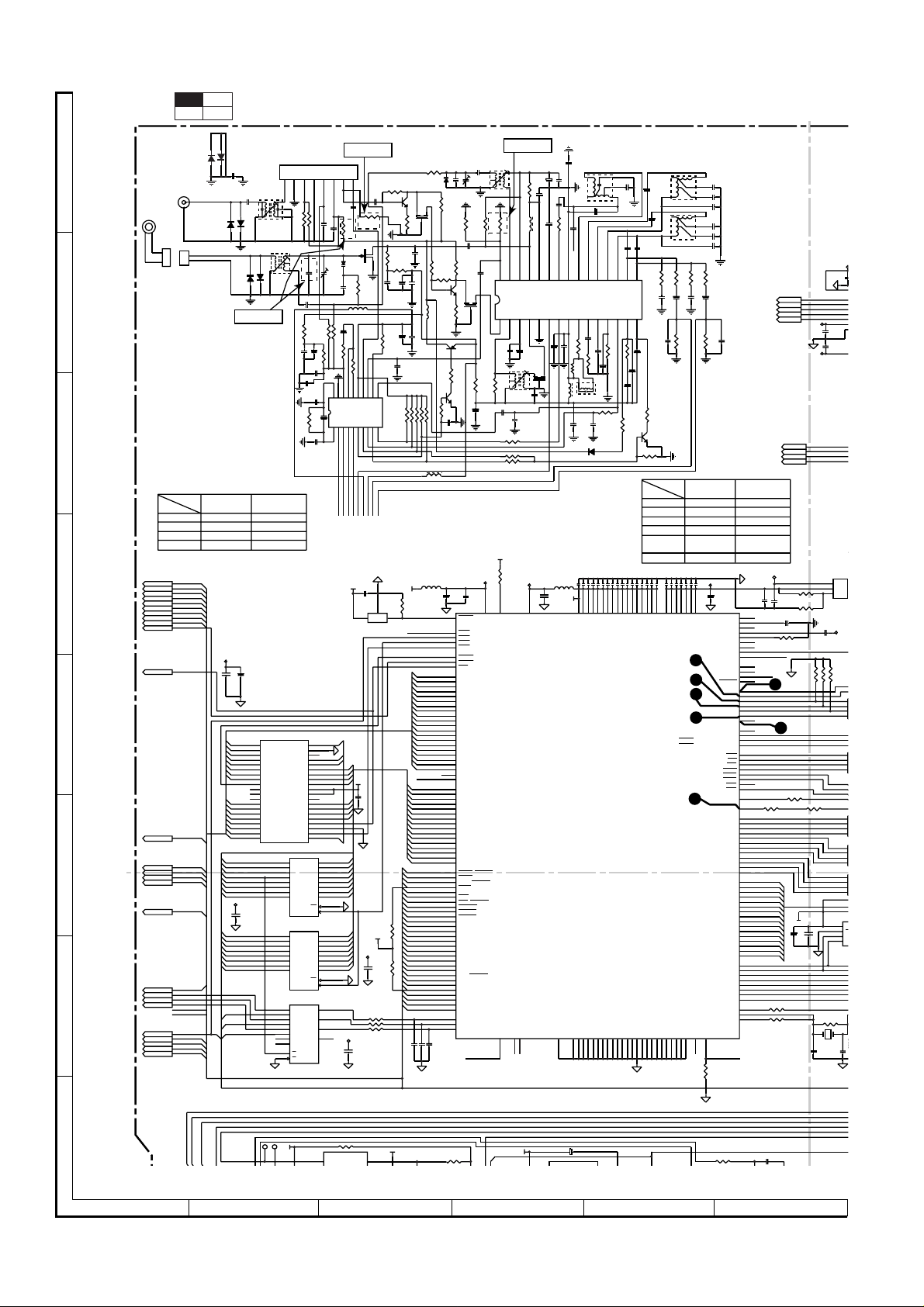
• NOTES ON SCHEMATIC DIAGRAM can be found on page 32.
1
23456
Figure 14 SCHEMATIC DIAGRAM (1/12)
VD002
1SV149B
CF001
10.7M J
0.022
C008
0.022
C011
0.022
C060
4.7K
4.7K
4.7K
R042
R041
R040
L007
FB103 600
A0
A1
A2
A3
A4
A5
A6
A7
A8
A9
A10
A11
A12
A13
A14
A15
A16
A17
A18
A19
A21
D0
D1
D2
D3
D4
D5
D6
D7
D8
D9
D10
D11
D12
D13
D14
D15
DCI_REQ
EAUX4[0]
DCI_ERR
AVIN1
DMUTE
DCLK
HDACK#
GU
TRAY-FWD
TRAY-REV
LSW
TOPEN-SW
TCLOSE-SW
HD0
HD1
HD2
HD3
HD4
HD5
HD6
HD7
DCI_FDS
TE_BIAS
RESB
AVIN2
HIRQB
WRQ_INT
FGO
IR
22PF
22PF
C1010
C1009
R007
C013
100K
5PF
R012
330 OHM
R037
10K
R013
100 OHM
R014
270K
Q003
2SC1009A
10uH
R016
L001
10K
R044
R043
100K
C077
0.022
10uH
C108
C109
0.1
10UF
RST 24
173
174
175
176
198
199
170
204
205
206
207
2
3
4
5
6
7
10
11
12
13
14
15
16
19
20
21
22
23
178
179
180
181
182
185
186
187
188
189
190
191
194
195
196
197
142
143
144
145
146
149
150
151
152
153
154
155
158
122
123
124
125
126
127
128
131
132
133
134
135
136
137
140
141
28
29
30
22PF
C1011
R814
10K
– 14 –
C014
T003
560P
OSC.
TC002
(22P)
2K
R036
R035
330 OHM
C010
0.022
0.022
C076
R015
330 OHM
10.7M J
CF002
AM OSC
FMIF
12345
Q004
2SA812
C026
R017
100K
R045
47 OHM
2SC1623
Q005
C033
0.022
C056
47UF
R046
R047
R048
VC33
R103
4.7K
VCC33E
111
25
RESET
LCS0
LCS1
AVCC(VDAC)
TDMDX/RSEL
LCS2
LCS3
LWRLL
LWRHL
LOE
LA0
LA1
LA2
LA3
LA4
LA5
LA6
LA7
LA8
LA9
LA10
LA11
LA12
LA13
LA14
LA15
LA16
LA17
LA18
LA19
LA20
LA21
LD0
LD1
LD2
LD3
LD4
LD5
LD6
LD7
LD8
LD9
LD10
LD11
LD12
LD13
LD14
LD15
HWRQ/DCI_REQ/EAUX4[1]
HRDQ/EAUX4[0]
HIRQ/DCI_ERR/EAUX4[7]
HRST/EAUX3[5]
HIORDY/EAUX3[3]
HWR/DCI_CLK/EAUX4[5]
HRD/DCI_ACK/EAUX4[6]
HIOCS16/CAMPCLK/EAUX3[4]
HCS1FX/EAUX3[7]
HCS3FX/EAUX3[6]
HA0/EAUX4[2]
HA1/EAUX4[3]
HA2/EAUX4[4]
HD0/DCI[0]/EAUX1[0]
HD1/DCI[1]/EAUX1[1]
HD2/DCI[2]/EAUX1[2]
HD3/DCI[3]/EAUX1[3]
HD4/DCI[4]/EAUX1[4]
HD5/DCI[5]/EAUX1[5]
HD6/DCI[6]/EAUX1[6]
HD7/DCI[7]/EAUX1[7]
HD8/DCI_FDS/EAUX2[0]
HD9/EAUX2[1]
HD10/EAUX2[2]
HD11/EAUX2[3]
HD12/EAUX2[4]
HD13/EAUX2[5]
HD14/EAUX2[6]
HD15/EAUX2[7]
TDMDR
TDMCLK
TDMFS
NC/CAMVS42CAMYUV0
SPDIFIN
HT-CN400DVA/
HT-CN500DVA ONLY
3.3K
R034
OSC
REG
AM MIX
FMIFB
C027
47UF
0.047
450 kHz
T008
AM IF
C073
0.022
C034
22PF
100 OHM
22K
22K
VCC33P
SYSTEM MICROCOMPUTER
CAMYUV1
202
203
D3V
C018
33UF
39uH
L002
AM RF
AMIF
CF003
C110
51
AVCC(PLL)
C020
0.1
C019
223
33UF
0.1
C022
22UF
1K
R033
C021
24252627282930
AFC
AM DEC
AM AGC
GND
TU LED
ST LED
7
6
C031
47UF
C030
L003
FB104
600
VC33
AVSS(PLL)
C867
C024
220PF
T004
BIAS
C023
10UF
330
C075
23222120191817
MPXL
MPXR
NPXIN
FM DEC
VCC ENDEC
FM SD
AM CF
9
8
11
10
0.047
C029
C028
R018
0.027
100 OHM
0.022
R020
51 OHM
2.7K
R019
10uH
T007
FM IF
R024
3.9K
C074
C036
0.022
0.022
D005
1N4148
C111-C134(0.1)
VC331VC3318VC3327VC3359VC3368VC3375VC3392VC3399VC33
IC106
ES6028
VSS
VSS
VSS
VSS
VSS
VSS
VSS
8
172634
43526067768491
47UF
T005
BIAS
C039
10UF
C025
30PF
C040
10UF
T006
BIAS
C049
C048
0.0015
0.0015
16
5.6K
LIN
RIN
AM SD
MUTE IF
121314
4.7K
R021
1UF
C032
104
VSS
VSS
VSS
R027
LOUT
ROUT
C050
0.015
IC001
LA1837
VCO
AM/FM
15
C054
0.0047
1UF
C041
3K
R022
C038
0.47UF
1UF
C037
R025
4.7K
R023
4.7K
Q006
2SC1623
R026
47K
MODEL
REF.No.
R110
R111
R112
R113, R114
R151, R161
R162
R163 0 OHM 33 OHM
130
148
157
159
164
183
193
201
93583
44
VC27
VC27
VC33
VC33
VSS
VSS
129
120
138
VC33
VC33
VC33
VC33
VSS
VSS
VSS
VSS
VSS
147
156
163
171
177
VC27
PCLKQSCN/CAMYUV5/AUX3[2]
VSSCN/CAMYUV6/EAUX3[1]
HSSCN/CAMYUV7/EAUX3[0]
VSS
VSS
VSS
184
192
200
VC33
VC33
VSS
VSS
98
103
R2IO[0..15]
C042
0.0022
C044
0.0047
C046
0.0022
C043
0.0022
C045
0.0047
C047
0.0022
6.8K
R028
5.6K
6.8K
R029
R030
IC001
LA1837
0.015
C052
4.7UF
C053
C051
4.7UF
TUNER
R031
R032
HT-CN400DVW/
HT-CN500DVW
120 OHM 33 OHM
300 OHM 33 OHM
0 OHM 10 OHM
300 OHM 33 OHM
300 OHM 33 OHM
VCC27
C135
10UF
121
139
172
YUV0/CAMYUV2
YUV1/VREF
VC27
VC27
VC27
VC27
YUV2/CDAC
YUV3/COMP
YUV4/RSET
AVSS(VDAC)
YUV5/YDAC
YUV6/VDAC
YUV7CAMYUV3
1
RBCK
2
TDMTSC
MCLK
3
TBCK
TWS/SEL_PLL2
TSD0/SEL_PLL0
TSD1/SEL_PLL1
4
TSD3
PCLK2XSCN/CAMYUV4
DCAS
DSCK/DOE
DRAS0
DBANK0/DRAS1
DBANK1/DRAS2
DCS1
DCS0
11
DSCK
DMA0
DMA1
DMA2
DMA3
DMA4
DMA5
DMA6
DMA7
DMA8
DMA9
DMA10
DMA11
AUX0
AUX1
AUX2
AUX3
AUX4
AUX5
AUX6
AUX7
XOUT
VSS
VSS
SPDIF/SEL_PLL3
NC/APLL
41
48
208
SPDIFO
R116
4.7K
R81
C055
0.0047
HT-CN400DVA/
HT-CN500DVA
RWS
RSD
TSD2
DWE
DQM
DB0
DB1
DB2
DB3
DB4
DB5
DB6
DB7
DB8
DB9
DB10
DB11
DB12
DB13
DB14
DB15
XIN
CLK
C1008
106
107
108
109
110
112
113
114
115
47
46
45
31
39
40
32
33
36
37
38
116
117
118
119
69
70
71
72
73
74
97
100
101
102
53
54
55
56
57
58
61
62
63
64
65
66
77
78
79
80
81
82
85
86
87
88
89
90
93
94
95
96
160
161
162
165
166
167
168
169
49
50
105
+2
SD2
SD2
SD1
SD1
SD0
SD0
LRCK
LRCK
BICK
BICK
+3.3V
C510
0.1
C511
0.1
+2.5V
RST
RST
AUX0
AUX0
AUX1
AUX1
AMCLK
AMCLK
IC11
B111
VCC
0.1
VREF
OK_DA
10
DMA0
DMA1
DMA2
DMA3
DMA4
DMA5
DMA6
DMA7
DMA8
DMA9
DMA10
DMA11
DB0
DB1
DB2
DB3
DB4
DB5
DB6
DB7
DB8
DB9
DB10
DB11
DB12
DB13
DB14
DB15
AUX0
AUX1
VFD-DA
EARDEC
RDS-DI
YU-D
SD
HWAITB
R113
R114
VOLT
REGUL
3
2
1
R145
C1007
120 OHM
0.1
R146
150 OHM
C136
0.1
MCLK
TBCK
TWS
TSD0
TSD1
TSD2
5
R119
10
C138
10UF
R104
270 OHM
300
B5V
C140
22PF
VCC
C137
0.1
4.7K
4.7K
4.7K
R107
R106
R108
R11
1
2
3
4
ENCODE1
ENCODE2
4
3
2
1
R160
R161
R162
R163
R112R118
10
4
3
2
1
4
3
2
1
4
3
2
1
8
7
6
S
5
S
C139
AT
0.1
EE
CLK
R115
56K
XL101
27 MHz
C141
C893
0.0015.6K
R84
Page 15

HT-CN400DVW/HT-CN400DVA/HT-CN500DVW/HT-CN500DVA
A
C575
C574
C576
C577
V
V
V
0
OUT1_A
OUT1_B
OUT6_A
R401
1K
C407 C408
0.01 0.01
R405
1K
C411
0.01
R409
1K
R413
1K
R417
1K
R421
1K
TU5V
XL801
16.9344 MHz
OUT6_B
C523
0.1
+3.3V
SPK_MUTE
OUT2_A
OUT2_B
OUT3_A
OUT3_B
OUT5_A
OUT5_B
OUT4_A
OUT4_B
R404
22K
R402
4.7K
R403
1K
22K
R408
C413
R406
150P
4.7K
R407
C412
1K
0.01
R412
22K
C417
R410
150P
4.7K
R411
C416C415
1K
0.010.01
R416
22K
C421
R414
150P
4.7K
R415
1K
C420C419
0.010.01
C422
0.1
R420
22K
C425
R418
150P
4.7K
R419
C424C423
1K
0.010.01
C426
0.1
R424
5.6K
C429
R422
332
4.7K
R423
C428C427
1K
0.010.01
C430
0.1
+5V
Q104
2SA812
R138
4.7K
R137
C197
10K
100UF
Q103
2SC1623
C865
10PF
D3V
R618
10K
Q605
2SC1623
C409
150P
2
3
4
C410
0.1
IC401B
RC4558D
5
8
C414
0.1
IC402A
4RC558D
2
3
4
C418
0.1
IC402B
RC4558D
6
5
8
IC403A
RC4558D
2
3
4
IC403B
RC4558D
6
5
8
TU12V
C198
100UF
1
IC401A
RC4558D
7
+12V
1
7
1
7
Q106
2SA812
R140
4.7K
Q105
2SC1623
C634
22UF
C522
0.1
C548
+3.3V
C547
0.1
C432
10UF
-12V
C433
10UF
C434
10UF
C435
10UF
C436
10UF
C437
10UF
+12V
R139
10K
+2.5V +2.5V +3.3V+3.3V+3.3V
0.1
0.1
0.1
C514
C516
C517
0.1
SD2
SD1
SD0
LRCK
BICK
RST
AUX0
AUX1
AMCLK
/
1007
120 OHM
1
6
R104
270 OHM
MCLK
TBCK
TWS
TSD0
TSD1
TSD2
300
R119
B5V
C138
10UF
C140
22PF
R84
SD2
SD1
SD0
LRCK
BICK
+3.3V
C510
0.1
C511
0.1
+2.5V
RST
AUX0
AUX1
AMCLK
IC115
B1117N
VOLTAGE
REGULATOR
3
2
1
R145
R146
150 OHM
VCC33E
C137
0.1
4.7K
4.7K
4.7K
R107
R106
R108
1
2
3
4
ENCODE1
ENCODE2
45
36
27
18
R160
R161
R162
R163
R112
10
45
36
27
4 MA4
3
2
1
4
3
2
1
8
7
6
5
C139
AT24C02N
0.1
EEPROM
CLK
R115
56K
XL101
27 MHz
+2.5V
R111
VCC
WC
SCL
+3.3V
R110
RA101
RA102
RA104
RA105
RA106
IC107
C142
C141
22PF
33x4
33x4
10x4
10x4
10x4
GNDSDA
VC33
C1006
R174
33 OHM
S0
S1
S2
0.001
0.1
C513C512
0.10.1
8
7
6
5
5
6
7
8
5
6
7
C591
0.001
AMCLK
BICK
LRCK
SD0
SD1
SD2
4.7K
VIDEO_SW
MA0
MA1
MA2
MA318
MA5
MA6
MA7
MA8
MA9
MA10
MA118
DB[0..15]
1
2
3
4
1 8
2 7
RA117
4.7Kx4
IC114
RT9164
FB102
100 OHM
10UF
C1005
0.1
C1004
C1003 C1002 C1000
10UF 10UF 10UF
R526
47K
C590
0.001
1
MVO
2
TEST_MODE
3
VDD3.3_1
4
GND_1
5
VDD2.5_1
6
SDI_78
7
SDI_56
8
SDI_34
9
SDI_12
10
LRCKI
11
BICKI
12
VDD3.3_2
13
GND_2
14
VDD2.5_2
15
RESET
16
PLL_BYPASS
C599
47PF
+3.3V
R503
10K
R502
10K
DOUT
72CE
72CLK
72DA
C100
MA[0..11]
VCC
RA118
4.7Kx4
3 6
4 5
1 8
2 7
3 6
4 5
+5V
FB101
100 OHM
+5V_1
VCC
123
C1001
0.1
DVD-CDB
LDON1
LDON2
DEFECTO
XHTR
0.1
C199
C515
60
61515657586255535264546359
PWDN
BICKO
GND_7
LRCKO
SDO_78
SDO_12
SDO_34
SDO_56
VDD3.3_7
VDD2.5_7
IC503
STA308
AUDIO
PROCESSOR
SDA
SCL
SA
XTI
VDDA_PLL
PLL_FILTER
GNDA_PLL
CKOUT
VDD2.5_3
VDD3.3_PLL
181917282027222123252632313029
24
R527
C601
3.3K
100PF
C600
0.0012
C602
100PF
GNDA
IC110
WM8772
6CH D/A 2CH A/D
1
AVDD
MODE
2
AGND
MCLK
3
OUT3R
BCLK
4
OUT3L
LRCK
5
OUT2R
DVDD
6
OUT2L
DGND
7
OUT1R
DIN1
8
VOUT1L
DIN2
9
DIN3
10
DOUT
11
VMID
ML/I2S
12
VREFP
MC/IWL
13
VREFN
MD/DM
14
MUTE
REFADC
FB115
600
0.1
C151
10UF
C152
EXCEPT FOR
HT-CN400DVA
MA0
23
MA1
24
MA2
25
MA3
26
MA4
29
MA5
30
MA6
31
MA7
32
MA8
33
MA9
34
MA10
22
MA11
35
38RCLK
37
CKE
19
CS0#
18
RAS0#
CAS# 17
WE#1516
DQMX
39
BANK0
20
BANK1
21
36
40
4Mx16 SDRAM (9ns)
74HC374
3
D0 Q0
4
D1 Q1
7
D2 Q2
8
D0
D3 Q3
13
D1
D4 Q4
14
D2
D5 Q5
17
D3
IC108
D6 Q6
18
D4
D7 Q7
1
OE
11LCS1#
CLK
33 OHM
R119
33 OHM
R120
33 OHM
R121
WRQ_INT
IO6
IO7
IO5
VDD2.5_6
GND_3
AINL
AINR
VCC
IO4
GND_6
VDD3.3_6
13
VDD3.3_3
OUT8_B
A0
A1
A2
A3
A4
A5
A6
A7
A8
A9
A10
A11
CLK
CKE
CS
RAS
CAS
WE
DQML
DQMH
BA0
BA1
NC
NC
2
5
6
9
12
15
16
19
IO3
49
50
EAPD
OUT1_B
OUT1_A
OUT2_A
OUT2_B
VDD2.5_5
VDD3.3_5
OUT3_A
OUT3_B
OUT4_A
OUT4_B
OUT5_A
OUT5_B
VDD2.5_4
VDD3.3_4
OUT6_A
OUT6_B
OUT7_A
OUT7_B
OUT8_A
C544
0.1
VDDA
C543
0.1
28
27
26
25
24
23
22
21
20
19
18
17
16
15
C153
10UF
IC109
33 OHM
SW1_VIDEO
R122
SYR
IO0
IO2
IO1
GND_5
GND_4
+2.5V
+
0.1
C154
DQ0
DQ1
DQ2
DQ3
DQ4
DQ5
DQ6
DQ7
DQ8
DQ9
DQ10
DQ11
DQ12
DQ13
DQ14
DQ15
Y3VTW
VCC
VCC
VCC
VCCQ
VCCQ
VCCQ
VCCQ
VSSQ
VSSQ
VSSQ
VSSQ
VSS
VSS
VSS
33 OHM
R123
RDS-DATA
TU-CE
EAPD
+2.5V
C521
+
0.1
C593
48
47
46
45
44
43
42
41
40
39
38
37
36
35
34
33
+3.3V
C545
0.1
L515
600
C603
22UF
L514
600
FB114
600
10UF
0.1
0.1
C155
C156
C158
VCC33
2
4
5
7
8
10
11
13
42
44
45
47
48
50
51
53
1
14
27
3
9
43
49
6
12
46
52
28
41
54
TUPO
VCC
R125
33 OHM
R124
33 OHM
TU-DI
TU-CL
YU-DO
SDB
TU5V
TU12V
IO12
IO11
IO15
IO13
IO14
2.2UF
C520
0.1
C592
+
2.2UF
+3.3V
+2.5V
C519
0.1
C518
0.1
+3.3V
+2.5V
C546
0.1
VCC
L-A
C401
10UF
10UF
0.1
0.1
0.1
C157
C159
FB116
600
DB0
DB1
DB2
DB3
DB4
DB5
DB6
DB7
DB8
DB9
DB10
DB11
DB12
DB13
DB14
DB15
C144
C145
C146
C147
C148
C149
C150
C143
0.1
IO9
IO8
IO10
R-A 6
C160
C161
VC33
SL-A
SR-A
10UF
C144-C150(0.1)
C-A
SUB-A
C406
10UF
TU-R
TU-L
T15
R891
T13
330 OHM
T14
T12
R890
C402
10UF
C403
10UF
C404
C405
10UF
• The numbers 1 to 5 , 10 , 11 , 13 , 14 are waveform numbers shown in page 37, 38.
19
GNDREF
20
GNDR1
14
21
22
23
24
25
26
27
28
29
30
31
32
33
C525
0.1
34
35
36
C528
0.1
19
20
21
22
23
24
25
26
27
28
29
30
31
32
33
C549
0.1
34
35
36
C551
0.1
R425
R426
R491
R427
R428
IC404B
RC4558D
VREG1
VREG1
VL
CONFIG
PWRDN
TRI-STATE
FAULT
TWARN
INLA
IC501
INLB
INRA
INRB
VREG2
VREG2
VSIG
VSIG GNDS
GNDREF
GNDR1
VREG1
VREG1
VL
CONFIG
PWRDN
TRI-STATE
FAULT
TWARN
INLA
IC502
INLB
INRA
INRB
VREG2
VREG2
VSIG
VSIG GNDS
VDAC
R130
75 OHM
IC406A
RC4558D
C458
R462
IC406A
1
C459
10UF
-12V
C460
R464
IC406B
7
C461
10UF
+12V
C438
47K
68K
R430
68K
6
5360K
360K
R429
+12V
56K
C526
0.1
R501
10K
C550
0.1
0.1
R504
10K
NC
OUTPL
OUTPL
VCC1P
PGND1P
PGND1N
VCC1N
OUTNL
OUTNL
OUTPR
OUTPR
STA505
VCC2P
PGND2P
POWER AMP.
PGND2N
VCC2N
OUTNR
OUTNR
NC
OUTPL
OUTPL
VCC1P
PGND1P
PGND1N
VCC1N
OUTNL
OUTNL
OUTPR
OUTPR
STA505
VCC2P
PGND2P
POWER AMP.
PGND2N
VCC2N
OUTNR
OUTNR
L105
2.4µF
C180 C181
470 470
47PF
15K
2
3
C462
4
0.1
47PF
15K
6
5
C463
8
0.1
47PF
C439
33K
10UF
7
IC404B
8
C443
0.1
18
17
16
+28V
15
14
13
12
11
10
9
8
+28V
7
6
5
4
3
2
1
18
17
16
+28V
15
14
13
12
11
10
9
8
+28V
7
6
5
4
3
2
1
R461
12K
R463
12K
IC406B
RC4558D
R431
R432
R433
R434
R492
C563
0.001
+
C567
1UF
+
C530
0.1
+
C568
1UF
C531
0.1
C564
0.001
+
C569
1UF
+
C552
0.1
+
C570
1UF
C553
0.1
C456
R459
R460
C457
10UF
IC404A
RC4558D
10UF
47K
68K
68K
68K
68K
L506
C535
30uH
1
R506
R515
R516
C595
L507
C533
30uH
1
L504
C536
30uH
1
R507
R517
R518
C596
C534
1
L505
30uH
C556
L518
1
30uH
R508
R519
R520
C597
C554
L519
1
30uH
L516
C557
30uH
1
R509
R521
C598
R522
C555
L517
1
30uH
CVBS1
IC405
TC4052BFN
MULTIPLEXE
13
X
100K
100K
3
Y
16
VDD
7
VEE
GND
C453
100UF
C455
100UF
C440
47PF
R435
33K
2
3
IC404
4
-12V
C444
0.1
1
C538
1
C539
1
C540
1
C541
1
C558
1
C559
1
C560
1
C561
X0
X1
X2
X3
Y0
Y1
Y2
Y3
A
B
INH
+7
C452
0.1
C454
0.1
-7
C
1
1
TCLOSE-SW
TCLOSE-SW
TOPEN-SW
TOPEN-SW
LSW
LSW
TRAY-REV
TRAY-REV
TRAY-FWD
TRAY-FWD
DMUTE
DMUTE
OSCIN
R894
68K
ADTE
IC810
RT9164
OSCIN
7
8 9 10 11 12
Figure 15 SCHEMATIC DIAGRAM (2/12)
– 15 –
Page 16

HT-CN400DVW/HT-CN400DVA/HT-CN500DVW/HT-CN500DVA
C
C
A
A
A
5
TOPEN-SW
TOPEN SW
VC33
A
A
A
L
C
C
4
P
3
2
0
7
SITUATION :
A
B
C
D
E
F
G
H
MECHANISM UNIT
MOTOR PWB (210)
MECHANISM UNIT
MOTOR PWB (210)
MECHANISM UNIT
FROM DVD
with LOADING
FROM
DVD
with SPIN/SLED
FROM
DVD
with PICKUP
PWB (210)
LSW
LSW
TRAY-REV
TRAY-REV
TRAY-FWD
TRAY-FWD
DMUTE
DMUTE
OSCIN
OSCIN
DCLK
DCLK
HIRQB
HIRQB
LWRHL
LWRHL
LOE#
LOE#
HD[0..7]
HD[0..7]
DCI_ERR
DCI_ERR
HCLK#
HCLK#
HDACK#
HDACK#
DCI_REQ
DCI_REQ
DCI_FDS
DCI_FDS
EAUX40
EAUX40
TDMDR
TDMDR
TDMCLK
TDMCLK
TDMFS
TDMFS
LCS1#
LCS1#
HIRQB
HIRQB
FGO
FGO
RESB
RESB
GU
GU
Servo control
100 OHM
CN801
R829
DRP
5
DRM
4
3
2
1
4.7K
R801
D3V
R803
4.7K
CN802
1
SLD-F
SLD-F
2 SLD-R
SLD-R
3
SP+
LSW
4
SP-
LSW
5
SPDP
DGND
6
SPDM
CN803
1
FCS-R
F-
2
TRK-D
F+
3
TRK-R
T+
4
FCS-D
T-
5
R8117
C
6
R8118
D
7
CD/DVD
8
R
R8119
9
A
R8120
10
B
11
F
12
GND-P
13
V
14
VC
15
E
16
NC
17
VR-CD
18
VR-DVD
19
LD-CD
20
LDS
MD
21
HFM
22
NC
23
LD-DVD
24
GND-LD
25
26
Q801
CM5783 GR
AGND
100 OHM
R830
4.7K
R802
R851
R816
10K
L801
600
18 OHM
100 OHM
R832
TCLOSE-SW
TOPEN-SW
1K
1K
1K
1K
R843
18 OHM
C818
0.001
AGND
VCC
C890 2P
R850
10K
C816
102
C817
C101
0.1
10UF
C102
10UF
A16 1
A15
A14
A13
A12
A11
A9
A8
WRLL#
A18
A7
A6
A5
A4
A3
A2
72CE
72CLK
72DA
DVD
S-B
S-A
S-BLNK
S-SWTCH
VCC
C104
0.1
VFDCE
VFDCLK
LMUTE
MUTE
TUPO
2259DA
2259CL
WM8739CE
DOUT
BICK
LRCK
OPEN TRAY : TRY-FWD :L
DRP
DRM
FCS-D
TRK-R
FCS-R
TRK-D
SP+
SPSLD-F
SLD-R
IC801
LA6560
MOTOR
DRIVER
AGND
C888 2P
C889 2P
AGND
C107
0.1
DMDR
DMCLK
DMFS
AGND
D0
D1
D2
D3
D4
D5
D6
D7
D8
D9
D10
D11
D15
D14
D13
D12
VREF-OUT
IC801
Q803
CM5783 GR
IMP809SEUR
VC33
C103
LCS2#
VCC
R150
R151
R152
VCC
C106
0.1
22K
S-GND
VCONT
MUTE1
VIN4
VIN4VIN4+
VREF-IN
VIN1-SW
LA6560
REG-OUT
REG-IN
VIN3+
VIN3-
VIN3
VIN2+
VIN2-
VIN2
VIN1+B
8.2K
8.2K
8.2K
8.2K
47K
1.2M
47K
2.2M
47K
47K
820K
22K
2.2M
22K
820K
1.2M
R825
3.3K
R822
10K
1
IC105
0.1
VC33
C105
0.1
36
35
34
33
32
31
30
29
28
38
27
26
25
24
23
22
21
20
19
AGND
R169
4.7K
33 OHM
33 OHM
23
R168
D5V
Q806
CM5783 GR
R823
10K
4.7K
IC105
IMP809SEUR
RESET
IC101
SST39VF080
MULTI-PURPOSE
FLASH
A17
40
A17
A16
2
A15
3
A14
4
A13
5
A12
6
A11
7
A9
8
A8
9
WE#
10
NC
11
NC
12
NC
13
A18
14
A7
15
A6
16
A5
17
A4
18
A3
19
A2A0CE#
20A1
A1
TRAY-REV
TRAY-FWD
R807
10K
PREF RF5V
C812
0.1
C813
47UF
AGND
CM5051 O
Q802
18 OHM
18 OHM
R818
R844
39
GND
38
NC
37
A19
A19
36
A10
A10
35
D7
DQ7
34
D6
DQ6
33
D5
DQ5
32
D4
DQ4
31
VCC
30
VCC
29
NC
D3
28
IC101
DQ3
D2
27
DQ2
D1
26
DQ1
D0
25
DQ0
24
LOE#
OE#
23
GND
22
LCS3#
21
A0
2
3
D0
Q0
5
4
D1
Q1
6
7
D2
Q2
9
8
D3
Q3
12
15
16
19
12
15
16
19
11
10
14
13
15
T4T3
C831
C814
0.1
C815
47UF
C820
0.001
C819
10UF
13
D4
Q4
14
D5
Q5
IC102
17
D6
Q6
18
D7
Q7
1
OE
11
CLK
74F374D
2
3
D0Q0
5
4
D1Q1
6
7
D2Q2
9
8
D3Q3
13
D4Q4
14
D5Q5
17
D6Q6
IC103
18
D7Q7
1
OE
11
CLK
74HC374
4
2
1Y
1A
3
1B
7
5
2Y
2A
6
2B
9
3Y
3A
3B
12
4A
4Y
4B
1
A/B
G
IC104
SN74F157A
TRY-REV :H STOP TRAY : TRY-FWD :L TRY-REV :LCLOSE TRAY : TRY-FWD :HTRY-REV :L DMUTE : H FCS,TRK,SPD,SLD : MOVE
R815
S8V
1
FWD
FWD
2
REV
REV
3
VCC2
4
C800
0.1
47UF
C805
0.1
R806
22K
VLO-
5
VLO+
6
VO4+
7
VO4-
8
VO3+
9
VO3-
0.1
37
FR FR
C803
10
VO2+
11
VO2-
12
VO1+
13
VO1-
14
VCC1
15
VIN1
16
VIN1-A
17
VIN1+A
18
VIN1-B
SLDO
R826
R827
R828
R831
R834
R835
R836
R837
R838
R839
R840
C891
2P
AGND
R845
470P
C833
R846
R847
R848
R849
Q805
CM5783 GR
TSTD1
TSTD0
AGND
R820
R821
4.7K
10K
LDD1
LDD2
DGND
R101
100K
C822
56PF
C824
56PF
R813
C809
0.1
R808
27K
LCS0#
LCS1#
LCS2#
LCS3#
WRLL#
LWRHL
LOE#
DCI_REQ
EAUX4[0]
DCI_ERR
AVIN1
DMUTE
DCLK
HDACK#
GU
TRAY-FWD
TRAY-REV
LSW
TOPEN-SW
TCLOSE-SW
HD0
HD1
HD2
HD3
HD4
HD5
HD6
HD7
DCI_FDS
TE_BIAS
RESB
AVIN2
HIRQB
WRQ_INT
FGO
IR
22PF
C1009
3.6K
R811
15K
PREF
AGND
C108
C109
0.1
10UF
RST 24
173
174
175
176
198
199
170
A0
204
A1
205
A2
206
A3
207
A4
2
A5
3
A6
4
A7
5
A8
6
A9
7
A10
10
A11
11
A12
12
A13
13
14
A14
15
A15
16
A16
19
A17
20
A18
A19
21
22
A21
23
178
D0
179
D1
180
D2
181
D3
182
D4
185
D5
186
D6
187
D7
188
D8
189
D9
190
D10
191
D11
194
D12
195
D13
196
D14
197
D15
142
143
144
145
146
149
150
151
152
153
154
155
158
122
123
124
125
126
127
128
131
132
133
134
135
136
137
140
141
28
29
30
22PF
22PF
C1011
C1010
R814
10K
DMUTE
IC804
IC41LV16256
DRAM
R812
10K
SREF
TDO
C810
47UF
R810
10K
FDO
R809
10K
SPDO
R868
3.3K
C840
56PF
RF5V
C821
56PF
C823
56PF
LDD1
LDS
Q804
CM5783 GR
111
25
RESET
LCS0
LCS1
AVCC(VDAC)
LCS2
TDMDX/RSEL
LCS3
LWRLL
LWRHL
LOE
LA0
LA1
LA2
LA3
LA4
LA5
LA6
LA7
LA8
LA9
LA10
LA11
LA12
LA13
LA14
LA15
LA16
LA17
LA18
LA19
LA20
LA21
LD0
LD1
LD2
LD3
LD4
LD5
LD6
LD7
LD8
LD9
LD10
LD11
LD12
LD13
LD14
LD15
HWRQ/DCI_REQ/EAUX4[1]
HRDQ/EAUX4[0]
HIRQ/DCI_ERR/EAUX4[7]
HRST/EAUX3[5]
HIORDY/EAUX3[3]
HWR/DCI_CLK/EAUX4[5]
HRD/DCI_ACK/EAUX4[6]
HIOCS16/CAMPCLK/EAUX3[4]
HCS1FX/EAUX3[7]
HCS3FX/EAUX3[6]
HA0/EAUX4[2]
HA1/EAUX4[3]
HA2/EAUX4[4]
HD0/DCI[0]/EAUX1[0]
HD1/DCI[1]/EAUX1[1]
HD2/DCI[2]/EAUX1[2]
HD3/DCI[3]/EAUX1[3]
HD4/DCI[4]/EAUX1[4]
HD5/DCI[5]/EAUX1[5]
HD6/DCI[6]/EAUX1[6]
HD7/DCI[7]/EAUX1[7]
HD8/DCI_FDS/EAUX2[0]
HD9/EAUX2[1]
HD10/EAUX2[2]
HD11/EAUX2[3]
HD12/EAUX2[4]
HD13/EAUX2[5]
HD14/EAUX2[6]
HD15/EAUX2[7]
TDMDR
TDMCLK
TDMFS
NC/CAMVS42CAMYUV0
SPDIFIN
R2IO0
R2IO1
R2IO2
R2IO3
R2IO4
R2IO5
R2IO6
R2IO7
MWEB
MRAS1B
R2A0
R2A1
R2A2
R2A3
R2A[0..8]
T5
R866
22K
C839
3P
R1
1K
R841
3.3K
646362616059585756555453525150
RFP
VCC
CAN
CAO
1
CAP
2
VCC
3
PDRF
4
PD1
5
PD2
6
PD3
7
PD4
8
GND
9
10
11
12
13
14
15
16
LA9703W
FIN1
DVD PLAYER
FIN2
PIN1
PIN2
TIN1
TIN2
LDD1
LDS1
LDD2
LDS2
GND
LDTH
171819202122232425262728293031
AGND
600
0.1
VC33
C110
51
RFOP
10
11
12
13
14
15
16
17
18
19
20
RF3V
1
2
3
4
5
6
7
8
9
RFON
DPD/TE
VCC
DQ0
DQ1
DQ2
DQ3
VCC
DQ4
DQ5
DQ6
DQ7
NC
NC
WE
RAS
NC
A0
A1
A2
A3
VCC
SREFPREF
N/C
LPC
WO/PP
VCCTHXHTR
C864
100P
GU
LDON2
LDON1
DVD-CDB
C835
100UF
SREF
AVSS(PLL)
C867
R865
8.2K
PHC
49
32
IC106
ES6028
VSS
8
47UF
IC804
R864
36K
BCAI
SREFI
PH
BH
ISET
WOC
PPN
PP
WO
TE
FE
RREC
CP
TEBL
FEBL
FC
BST
SGC
AGND
VC331VC3318VC3327VC3359VC3368VC3375VC3392VC3399VC33
VSS
VSS
VSS
VSS
VSS
VSS
VSS
VSS
172634
43526067768491
40
VSS
39
DQ15
38
DQ14
37
DQ13
36
DQ12
35
VSS
34
DQ11
33
DQ10
32
DQ9
31
DQ8
30
NC
29
LCAS
28
UCAS
27
OE
26
IC41LV16256
A8
25
A7
24
A6
23
A5
22
A4
21
VSS
DGND
C836
C838
0.1
0.1
AGND
RF3V
48
47
46
45
44
43
42
41
40
39
38
37
36
35
34
33
AVCC(PLL)
SYSTEM MICROCOMPUTER
CAMYUV1
202
203
D3V
C837
100UF
N/C
RFN
GND
PREF
FSET
12
IC802
LDON1
LDON2
AGOF
BCAGUDVD/CD
104
VSS
C834
C830
C827
130
148
VC33
VSS
98
103
R2IO[0..15]
R2IO15
R2IO14
R2IO13
R2IO12
R2IO11
R2IO10
R2IO9
R2IO8
PREF
1UF
0.0047
R861
R860
R859
R857
157
VC33
VC33
VSS
VSS
120
C832
R863
33K
C829
0.0047
0.047
93583
44
159
164
183
193
201
VC27
VC27
VC33
VC33
VC33
VC33
VC33
PCLKQSCN/CAMYUV5/AUX3[2]
VSS
VSS
VSS
VSS
VSS
VSS
VSS
VSS
129
138
147
156
163
171
177
184
192
LM358MX
LOW POWER
DUAL OPE AMP.
MCASLB
MCASUB
MOEB
R2A8
R2A7
R2A6
R2A5
R2A4
47UF
SREF
R862
33K
6.8K
6.8K
6.8K
R858
10K
C828
1UF
R856
R855
R854
R853
C826
0.0047
C825
TBAL
FBAL
FC
BST
SGC
XHTR
DEFECTO
C135
10UF
121
139
172
YUV0/CAMYUV2
YUV1/VREF
VC27
VC27
VC27
VC27
VC27
YUV2/CDAC
YUV3/COMP
YUV4/RSET
AVSS(VDAC)
YUV5/YDAC
YUV6/VDAC
YUV7CAMYUV3
1
2
TDMTSC
3
TBCK
TWS/SEL_PLL2
TSD0/SEL_PLL0
TSD1/SEL_PLL1
4
PCLK2XSCN/CAMYUV4
VSSCN/CAMYUV6/EAUX3[1]
HSSCN/CAMYUV7/EAUX3[0]
DSCK/DOE
DRAS0
DBANK0/DRAS1
DBANK1/DRAS2
11
DSCK
DMA0
DMA1
DMA2
DMA3
DMA4
DMA5
DMA6
DMA7
DMA8
DMA9
DMA10
DMA11
VSS
VSS
VSS
SPDIF/SEL_PLL3
NC/APLL
41
48
200
208
SPDIFO
R116
4.7K
R81
R82
IC809
DGND
C892
0.1
DGND
56PF
C843
62K
AGND
6.8K
6.8K
10K
WO
33K
SREF
100P[
R842
39K
R852
5.6K
AGND
1
VREF
OK_DA
DMA0
DMA1
DMA2
DMA3
DMA4
DMA5
DMA6
DMA7
DMA8
DMA9
DMA10
DMA11
DB0
DB1
DB2
DB3
DB4
DB5
DB6
DB7
DB8
DB9
DB10
DB11
DB12
DB13
DB14
DB15
AUX0
AUX1
VFD-DA
EARDEC
RDS-DI
YU-D
SD
HWAITB
R113
R114
R83
123
8
560P
R145
C1007
120 OHM
0.1
R146
150 OHM
C136
0.1
10
MCLK
TBCK
TWS
TSD0
TSD1
TSD2
5
R119
10
C138
10UF
0.001
4.7K
DGND
S8V
0.1
C894
R104
270 OHM
300
B5V
C140
22PF
R84
10K
R85
4.7K
VCC3
C137
0.1
4.7K
4.7K
4.7K
R107
R106
R108
R111
R
1
2
3
4
ENCODE1
ENCODE2
R
4
3
2
1
R160
R161
R162
R163
R112R118
R
10
4
3
2
1
R
4
3
2
1
R
4
3
2
1
I
8
VC
7
W
6
SC
5
SD
C139
AT2
0.1
EE
CLK
R115
56K
XL101
27 MHz
C141
22PF
1N4148
C89
R86
0.01
18K
D801
ADJV
ADRREC
ADPH
ADBH
ADTE
ADFE
C849
470P
RFP
C850
470P
RFN
1
R870
4.
R871
BHC
WO
TEC
TSTD1
TSTD0
FC
BST
TBAL
FBAL
SGC
SLDO
SPDO
TDO
FDO
R2A[0..8]
C1008
0.1
106
107
108
109
110
112
113
114
115
47
RBCK
46
RWS
45
RSD
31
39
MCLK
40
32
33
36
37
TSD2
38
TSD3
116
117
118
119
69
DCAS
70
71
DWE
72
73
74
97
DCS1
100
DCS0
101
DQM
102
53
54
55
56
57
58
61
62
63
64
65
66
77
DB0
78
DB1
79
DB2
80
DB3
81
DB4
82
DB5
85
DB6
86
DB7
87
DB8
88
DB9
89
DB10
90
DB11
93
DB12
94
DB13
95
DB14
96
DB15
160
AUX0
161
AUX1
162
AUX2
165
AUX3
166
AUX4
167
AUX5
168
AUX6
169
AUX7
49
XIN
50
XOUT
105
CLK
C893
5.6K
5.6K
4
567
C847
0.001
0.0015
560P
C845
C846
C848
AGND
0.001
C844
• NOTES ON SCHEMATIC DIAGRAM can be found on page 32.
1
23456
Figure 16 SCHEMATIC DIAGRAM (3/12)
– 16 –
Page 17

HT-CN400DVW/HT-CN400DVA/HT-CN500DVW/HT-CN500DVA
O
P
F
X
2
5
0
1
R145
C1007
120 OHM
0.1
R146
150 OHM
C136
0.1
10
MCLK
TBCK
TWS
TSD0
TSD1
TSD2
5
R119
10
1
10
11
C138
10UF
DA
EC
DI
ITB
R104
270 OHM
300
B5V
C140
22PF
R112
10
C139
0.1
CLK
VCC33E
C137
0.1
4.7K
4.7K
4.7K
R107
R106
R108
R111
RA101
1
2
3
4
ENCODE1
ENCODE2
RA102
45
36
27
18
R160
R161
R162
R163
RA104
45
36
27
RA105
4 MA4
3
2
1
RA106
4
3
2
1
IC107
8
VCC
7
WC
6
SCL
5
AT24C02N
EEPROM
R115
56K
XL101
27 MHz
C141
R110
22PF
33x4
33x4
33 OHM
10x4
10x4
10x4
GNDSDA
VC33
C142
0.001
C1006
8
7
6
5
R174
5
6
7
8
5
6
7
DB[0..15]
1
S0
2
S1
3
S2
4
10UF
C1005
0.1
AMCLK
BICK
LRCK
SD0
SD1
SD2
4.7K
VIDEO_SW
MA0
MA1
MA2
MA318
MA5
MA6
MA7
MA8
MA9
MA10
MA118
1 8
2 7
3 6
4 5
RA117
4.7Kx4
IC114
RT9164
FB102
+5V_1
123
100 OHM
0.1
C1004
C1003 C1002 C1000
10UF 10UF 10UF
MA[0..11]
1 8
FB101
100 OHM
C1001
0.1
2 7
3 6
VCC
1
MODE
2
MCLK
3
BCLK
4
LRCK
5
DVDD
6
DGND
7
DIN1
8
DIN2
9
DIN3
10
DOUT
DOUT
11
72CE
ML/I2S
12
72CLK
MC/IWL
72DA
13
MD/DM
14
MUTE
FB115
0.1
C151
10UF
C152
EXCEPT FOR
HT-CN400DVA
C100
CKE
CS0#
RAS0#
CAS# 17
WE#1516
DQMX
BANK0
BANK1
VCC
RA118
4.7Kx4
4 5
74HC374
3
4
7
8
D0
13
D1
14
D2
17
D3
18
D4
1
11LCS1#
R119
R120
R121
+5V
0.1
C199
28
AVDD
27
AGND
26
OUT3R
25
OUT3L
24
OUT2R
23
OUT2L
22
OUT1R
21
VOUT1L
20
AINL
19
AINR
18
VMID
17
VREFP
16
VREFN
15
REFADC
C153
VCC
600
10UF
MA0
23
A0
MA1
24
A1
MA2
25
A2
MA3
26
A3
MA4
29
A4
MA5
30
A5
MA6
31
A6
MA7
32
A7
MA8
33
A8
MA9
34
A9
MA10
22
A10
MA11
35
A11
38RCLK
CLK
37
IC109
CKE
19
CS
18
RAS
CAS
WE
DQML
39
DQMH
20
BA0
21
BA1
36
NC
40
NC
4Mx16 SDRAM (9ns)
2
D0 Q0
5
D1 Q1
6
D2 Q2
9
D3 Q3
12
D4 Q4
15
D5 Q5
16
IC108
D6 Q6
19
D7 Q7
OE
CLK
33 OHM
33 OHM
33 OHM
33 OHM
SW1_VIDEO
R122
0.1
C154
DQ0
DQ1
DQ2
DQ3
DQ4
DQ5
DQ6
DQ7
DQ8
DQ9
DQ10
DQ11
DQ12
DQ13
DQ14
DQ15
Y3VTW
VCC
VCC
VCC
VCCQ
VCCQ
VCCQ
VCCQ
VSSQ
VSSQ
VSSQ
VSSQ
VSS
VSS
VSS
33 OHM
R123
R124
SYR
RDS-DATA
TU-CE
TU-DI
10UF
C155
TUPO
33 OHM
TU-CL
0.1
C156
R125
YU-DO
2
4
5
7
8
10
11
13
42
44
45
47
48
50
51
53
1
14
27
3
9
43
49
6
12
46
52
28
41
54
FB114
600
33 OHM
SDB
TU5V
C158
VCC33
0.1
VCC
TU12V
VCC
10UF
0.1
0.1
0.1
C157
C159
C160
C161
FB116
VC33
600
DB0
DB1
DB2
DB3
DB4
DB5
DB6
DB7
DB8
DB9
DB10
DB11
DB12
DB13
DB14
DB15
C144
C145
C146
C147
C148
C149
C144-C150(0.1)
C150
C143
0.1
R401
1K
L-A
C401
10UF
R405
1K
R-A 6
C402
10UF
R409
1K
SL-A
C403
10UF
R413
SR-A
C404
10UF
R417
C-A
C405
10UF
R421
1K
SUB-A
C406
10UF
TU5V
TU-R
TU-L
R402
4.7K
C407 C408
0.01 0.01
R406
C411
0.01
R410
R414
1K
1K
R422
4.7K
C197
100UF
4.7K
C412
4.7K
C416C415
0.010.01
4.7K
C420C419
0.010.01
R418
4.7K
C424C423
0.010.01
C428C427
0.010.01
0.01
Q104
2SA812
R408
R138
4.7K
2SC1623
R404
C409
22K
150P
2
R403
3
1K
C410
0.1
22K
IC401B
C413
RC4558D
150P
R407
5
1K
C414
R412
0.1
22K
IC402A
C417
4RC558D
150P
2
R411
3
1K
C418
R416
0.1
22K
IC402B
C421
RC4558D
150P
6
R415
1K
5
C422
0.1
R420
22K
IC403A
C425
RC4558D
150P
2
R419
3
1K
C426
0.1
R424
5.6K
IC403B
C429
RC4558D
332
6
R423
5
1K
C430
0.1
+5V
TU12V
C198
100UF
R137
10K
Q103
IC401A
RC4558D
4
8
4
8
4
8
Q106
2SA812
1
1
7
+12V
7
1
7
R140
4.7K
Q105
2SC1623
C432
10UF
-12V
C433
10UF
C434
10UF
RC4558D
C435
10UF
C436
10UF
C437
10UF
IC404B
+12V
R139
10K
RC4558D
IC406A
1
C459
10UF
-12V
IC406B
7
C461
10UF
+12V
47K
R425
68K
R426
R430
68K
R491
R427
360K
R428
R429
56K
VDAC
R130
75 OHM
IC406A
C458
R462
4
C460
R464
8
C438
47PF
6
5360K
8
+12V
L105
2.4µF
C180 C181
470 470
47PF
15K
2
3
C462
0.1
47PF
15K
6
5
C463
0.1
C439
33K
10UF
7
IC404B
C443
0.1
R461
R459
12K
R463
12K
IC406B
RC4558D
R431
R432
R433
R434
R492
10UF
C456
R460
C457
10UF
47K
68K
68K
68K
68K
-12V
IC404A
RC4558D
CVBS1
IC405
TC4052B
MULTIPLE
13
X
100K
100K
3
Y
16
VDD
7
VEE
C453
100UF
C455
100UF
C440
R435
2
3
4
X0
X1
X2
X3
Y0
Y1
Y2
Y3
A
B
INH
GND
C45
0.1
C4
0.1
47PF
33K
1
IC4
C444
0.1
TCLOSE-SW
TCLOSE-SW
TOPEN-SW
TOPEN-SW
LSW
LSW
TRAY-REV
TRAY-REV
TRAY-FWD
TRAY-FWD
DMUTE
DVD-CDB
LDON1
LCS1#
LDON2
DEFECTO
XHTR
T20
SREF
10
11
12
13
14
15
16
17
18
19
20
21
22
23
24
25
26
27
28
29
30
31
32
33
34
35
36
37
38
39
40
41
42
43
44
D8
DGND
R8116
1
2
3
4
5
6
7
8
9
174
175
176
DVSS
6.8K
DVDD0
AD1
AD0
JV
RREC
RF-PH
RF-BH
TE
FE
TEST0
EFMINP
TEST1
EFMINN
SLCLPFO
SLCLPFI
SLC01
SLC02
AVDD1
AVSS
BHC
WO
TEC
VREF
TSTD1
TSTD0
F0
BST
TBAL
FBAL
SGC
7
SLDO
SPDO
8
TDO
FDO
DVDD0
DVSS
FG
6
HIRQB
HWAITB
HRESB
HRDB
HWRB
HCSB
HDAT0
DVDD1
DVSS
HDAT1
454647
D9
D10
0.001
R84
10K
.7K
DGND
V
1N4148
C895
R86
R85
4.7K
0.1
C894
18K
ADJV
ADRREC
ADPH
ADBH
ADTE
ADFE
RFP
RFN
R870
R871
D801
C849
470P
C850
470P
BHC
WO
TEC
TSTD1
TSTD0
FC
BST
TBAL
FBAL
SGC
SLDO
SPDO
TDO
FDO
R2A[0..8]
0.01
AD0
DGND
C851
0.1
100K
4.7K
D3V
AGND
FGO
INT_DEC
RDY
RESB
RD
WR
HFLIO
WRQ_INT
R2IO15
R2IO14
R2IO0
R2IO6
R2IO7
R2IO4
R2IO5
R2IO2
R2IO1
168
RFP0
166
167
DEFECTI
DEFECTO
R2IO3
154
155
160
152
153
156
157
158
159
165
161
162
163
164
MD0
MD1
MD2
MD3
MD4
MD5
MD6
MD7
DVSS
DVDD1
DVDD3
DVDD3
DVSS
MD15
T19
169
173
170
171
172
RFP1
RFP2
RFP3
TESIO
T15
R2IO12
R2IO11
R2IO9
R2IO8
R2IO13
R2IO10
143
144
145
149
146
147
148
150
151
MD9
MD8
DVSS
DVSS
MD10
MD11
MD12
MD13
MD14
DVDD1
9
IC803
LC78663WNRW
DVD FRONT END
HDAT2
HDAT3
HDAT4
HDAT5
4849505152535455565758596263646568697071727374787980818283
D11
D12
D13
D14
HDAT6
HDAT7
HADR0
A1A2A3A4A5A6A7
D15
HADR1
HADR2
HADR3
HADR4
MWEB
MRAS1B
HADR5
HADR6
606166
MWEB
MRAS1B
DVDD3
DVSS
MOEB
MCASUB
MA0
MA1
MA2
MA3
67
R2A2
R2A0
R2A1
R2A3
MCASLB
MA4
MA5
MA6
MA7
MA8
MA9
MA10
HADR7
757677
MCASUB
MCASLB
A8A9A10
R2A8
R2A4
R2A5
R2A6
R2A7
MOEB
142
HADR8
T14
DOUT
141
T13
140
EFLG
HADR9
A11
T12
139
FSX
DVDCKIO
HADR10
HADR11
A12
138
A13
137
TEST2
X16MIO
C2F
HADR12
84
136
DVSS
ROMXA
858687
135
134
XOUT
ROMCK
R891
330 OHM
R890
1M
133
XIN
DVDD2
LRSY
DVDD1
88
DVDD0
VCOC
VRPFR
VPDO
AVDD3
JVRVO
JVAIN
JVCPC
JVCPI
AVDD2
DVDFR
PISET
PPDO
VCOCTL
DVDD0
EFMOUT
AVD7
AVD6
AVD5
AVD4
AVD3
AVD2
AVD1
AVD0
AVERRB
AVSCTB
AVDACK
AVACKO
AVREQI
EMPH
DVSS
AVSS
JVAO
AVSS
CDFR
FISET
FPDO
DVSS
DVSS
PCN
PCK
LF3
LF2
LF1
XL801
16.9344 MHz
C866
10PF
132
131
130
129
128
127
126
125
124
123
122
121
120
119
118
117
116
115
114
113
112
111
110
109
108
107
106
105
104
103
102
101
100
99
98
97
96
95
94
93
92
91
90
89
C865
10PF
D3V
D2V
L802
600
A2.5V
AGND
DGND
R887
R883
6.8K
C859
C858
T11
C855
0.1
T10
T9
INT_DEC
T8
RD
SN74LVC23ANS
QUADF 2-1/P OR GATE
10K
C856
0.1
AVERRB#
AVSCTB
AVDACK#
AVDENB#
AVREQI
DGND
0.1
0.1
AVD7
AVD6
AVD5
AVD4
AVD3
AVD2
AVD1
AVD0
C861
560P
R882
R881
R880
R879
R878
R875
680 OHM
1
2
3
4
5
6
7
IC807
Q904A
DDTC114 E
R889
5.6K
R888
220 OHM
R876
1.2K
IC807
A1
B1
Y1
A2
B2
Y2
VSS Y3
R894
68K
ADTE
D901A
1N4148
DEFECTO
R893
10K
TE_BIAS
AGND
C854
0.1
C863
0.1
C862
0.01
ADJV
C860
0.01
10K
1.2K
1.8K
22K
22K
14
VCC
13
B4
12
A4
11
Y4
10
B3
9
A3
8
D3V
0.1
0.1
C875
C877
0.1
0.1
C874
0.1
C878
C876
AGND
DGND
RA801
10x4
1
2
3
4
1
2
3
4
10x4
RA802
10x4
RA803
1
2
3
4
D3V
C896
DGND
0.1
R8106
100 OHM
C897
150P
DGND
LCS1#
RDY
C961
0.1
C951
0.1
0.1
0.1
0.1
C883
C881
C879
0.1
0.1
C880
C884
C882
HD7
8
HD6
7
HD5
6
5 HD4
8
HD3
7
HD2
6
HD1
5 HD0
8
7
6
5
R873
10 OHM
IC808
1
2
3
4
5
6
7
SN74HC14NS
SN74HC14NS
INVERTER
RF5V
C885
47UF
0.1
I1
O1
I2
O2
I3
O3
VSS
IC808
MGND
AGND
VCC
D5V S5V
FB903
600
C960
47UF
FB904
600
C950A
47UF
C887
47UF
D3V
14
13
I6
12
O6
11
I5
10
O5
9
I4
8
O4
D5V
R8115
R8113
100 OHM
C899C898
150P0.1
OSCIN
IC810
RT9164
A3V
C955
47UF
C957
0.1
AGND
D2V
C959
0.1
HD[0..7]
DCI_ERR
DCI_FDS
DCLK
HDACK#
DCI_REQ
LWRHL
10K
R8109
330 OHM
C81
220P
LOE#
TDMFS
TDMCLK
TDMDR
HWAITB
HIRQB
LCS1#
FGO
RESB
GU
DMUTE
OSCIN
123
D5V
0.1
C954
0.1
C952
C953
47UF
DGND
D3VA3V
FB901
A3VRF3V
600
FB902
600
C956
47UF
Q903A
2SC1623
D3V
C958
47UF
DGND
P
HD[0..7]
DCI_ERR
DCI_FDS
DCLK
HDACK#
DCI_REQ
LWRHL
DGND
LOE#
TDMFS
TDMCLK
TDMDR
HWAITB
HIRQB
LCS1#
FGO
RESB
GU
• The numbers 1 to 12 are waveform numbers shown in page 37, 38.
7
8 9 10 11 12
Figure 17 SCHEMATIC DIAGRAM (4/12)
– 17 –
Page 18

HT-CN400DVW/HT-CN400DVA/HT-CN500DVW/HT-CN500DVA
0
2
L
7
SITUATION :
OUT1_A
OUT1_B
OUT6_A
R401
1K
C407 C408
0.01 0.01
R405
1K
C411
0.01
R409
1K
R413
1K
R417
1K
R421
1K
TU5V
C197
100UF
OUT6_B
SPK_MUTE
R618
Q605
10K
2SC1623
OUT2_A
OUT2_B
OUT3_A
OUT3_B
OUT5_A
OUT5_B
OUT4_A
OUT4_B
R404
C409
22K
R402
4.7K
R406
R410
R414
R422
4.7K
150P
2
R403
3
1K
4
C410
0.1
22K
R408
IC401B
C413
RC4558D
150P
4.7K
R407
C412
5
1K
0.01
4.7K
C416C415
0.010.01
4.7K
C420C419
0.010.01
R418
4.7K
C424C423
0.010.01
C428C427
0.010.01
Q104
2SA812
R415
R138
4.7K
Q103
2SC1623
8
C414
R412
0.1
22K
IC402A
C417
4RC558D
150P
2
R411
3
1K
4
C418
R416
0.1
22K
IC402B
C421
RC4558D
150P
6
1K
5
C422
8
0.1
R420
22K
IC403A
C425
RC4558D
150P
2
R419
3
1K
C426
4
0.1
R424
5.6K
IC403B
C429
RC4558D
332
6
R423
5
1K
C430
8
0.1
+5V
TU12V
C198
100UF
R137
10K
R526
47K
C590
0.001
1
MVO
2
TEST_MODE
3
VDD3.3_1
4
GND_1
5
VDD2.5_1
6
SDI_78
7
SDI_56
8
SDI_34
9
SDI_12
10
LRCKI
11
BICKI
12
VDD3.3_2
13
GND_2
14
VDD2.5_2
15
RESET
16
PLL_BYPASS
R503
10K
R502
10K
6CH D/A 2CH A/D
DOUT
72CE
72CLK
72DA
C151
10UF
C100
VCC
RA118
4.7Kx4
+5V
0.1
C199
+2.5V +2.5V +3.3V+3.3V+3.3V
0.1
C514
0.1
C515
60
61515657586255535264546359
PWDN
GND_7
LRCKO
SDO_12
SDO_34
SDO_56
SDO_78
VDD2.5_7
VDD3.3_7
IC503
STA308
AUDIO
PROCESSOR
SDA
SCL
SA
XTI
VDDA_PLL
PLL_FILTER
GNDA_PLL
CKOUT
VDD3.3_PLL
181917282027222123252632313029
24
R527
C601
3.3K
100PF
C600
0.0012
C602
100PF
GNDA
IC110
WM8772
1
MODE
2
MCLK
3
BCLK
4
LRCK
5
DVDD
6
DGND
7
DIN1
8
VOUT1L
DIN2
9
DIN3
10
DOUT
11
ML/I2S
12
MC/IWL
13
MD/DM
14
MUTE
REFADC
FB115
600
0.1
C152
EXCEPT FOR
HT-CN400DVA
MA0
23
MA1
24
MA2
25
MA3
26
MA4
29
MA5
30
MA6
31
MA7
32
MA8
33
MA9
34
MA10
22
MA11
35
38RCLK
37
CKE
19
CS0#
18
RAS0#
CAS# 17
WE#1516
DQMX
39
BANK0
20
BANK1
21
36
40
4Mx16 SDRAM (9ns)
74HC374
3
D0 Q0
4
D1 Q1
7
D2 Q2
8
D0
D3 Q3
13
D1
D4 Q4
14
D2
D5 Q5
17
D3
IC108
D6 Q6
18
D4
D7 Q7
1
OE
11LCS1#
CLK
33 OHM
R119
33 OHM
R120
33 OHM
R121
C516
BICKO
VDD2.5_3
AVDD
AGND
OUT3R
OUT3L
OUT2R
OUT2L
OUT1R
VREFP
VREFN
0.1
VDD2.5_6
GND_3
AINL
AINR
VMID
VCC
A0
A1
A2
A3
A4
A5
A6
A7
A8
A9
A10
A11
CLK
CKE
CS
RAS
CAS
WE
DQML
DQMH
BA0
BA1
NC
NC
0.1
C517
GND_6
VDD3.3_6
13
VDD3.3_3
OUT8_B
2
5
6
9
12
15
16
19
49
50
EAPD
OUT1_B
OUT1_A
VDD2.5_5
VDD3.3_5
VDD2.5_4
VDD3.3_4
OUT7_A
OUT7_B
OUT8_A
C544
0.1
VDDA
C543
0.1
28
27
26
25
24
23
22
21
20
19
18
17
16
15
C153
10UF
IC109
33 OHM
SW1_VIDEO
R122
SYR
OUT2_A
OUT2_B
GND_5
OUT3_A
OUT3_B
OUT4_A
OUT4_B
OUT5_A
OUT5_B
GND_4
OUT6_A
OUT6_B
+2.5V
L515
+
L514
10UF
0.1
C155
C154
DQ0
DQ1
DQ2
DQ3
DQ4
DQ5
DQ6
DQ7
DQ8
DQ9
DQ10
DQ11
DQ12
DQ13
DQ14
DQ15
Y3VTW
VCC
VCC
VCC
VCCQ
VCCQ
VCCQ
VCCQ
VSSQ
VSSQ
VSSQ
VSSQ
VSS
VSS
VSS
TUPO
33 OHM
R123
R124
RDS-DATA
TU-CE
TU-DI
C545
600
C603
22UF
600
33 OHM
TU-CL
0.1
YU-DO
0.1
C156
2
4
5
7
8
10
11
13
42
44
45
47
48
50
51
53
1
14
27
3
9
43
49
6
12
46
52
28
41
54
R125
+3.3V
FB114
SDB
48
47
46
45
44
43
42
41
40
39
38
37
36
35
34
33
600
33 OHM
TU5V
0.1
C158
VCC33
VCC
TU12V
EAPD
+2.5V
C521
+
0.1
C593
2.2UF
C520
0.1
C592
+
2.2UF
+3.3V
+2.5V
C519
0.1
C518
0.1
+3.3V
+2.5V
C546
0.1
VCC
L-A
C401
10UF
10UF
0.1
0.1
0.1
C160
600
C161
VC33
SR-A
C144-C150(0.1)
SUB-A
R-A 6
C402
10UF
SL-A
C403
10UF
C404
10UF
C-A
C405
10UF
C406
10UF
TU-R
TU-L
C157
C159
FB116
DB0
DB1
DB2
DB3
DB4
DB5
DB6
DB7
DB8
DB9
DB10
DB11
DB12
DB13
DB14
DB15
C144
C145
C146
C147
C148
C149
C150
C143
0.1
A
+2.5V
+3.3V
C513C512
0.10.1
SD2
B
C
SD1
SD0
LRCK
K
BICK
K
+3.3V
C510
0.1
C511
0.1
+2.5V
RST
RST
AUX0
AUX0
AUX1
AUX1
AMCLK
MCLK
IC115
B1117N
VOLTAGE
REGULATOR
3
BCK
WS
SD0
SD1
SD2
CLK
19
120 OHM
R104
270 OHM
300
2
1
R145
R146
150 OHM
C137
0.1
4.7K
4.7K
4.7K
R107
R106
R108
ENCODE1
ENCODE2
R160
R161
R162
R163
R112
10
D
E
F
B5V
8
7
6
5
138
C139
AT24C02N
0UF
0.1
EEPROM
CLK
G
R115
56K
XL101
27 MHz
C140
22PF
C591
0.001
VCC33E
R110
AMCLK
R111
BICK
RA101
33x4
LRCK
8
1
2
3
4
45
36
27
18
45
36
27
4 MA4
3
2
1
4
3
2
1
RA102
RA104
RA105
RA106
IC107
VCC
WC
SCL
C142
C141
22PF
33x4
33 OHM
10x4
10x4
10x4
S0
S1
S2
GNDSDA
VC33
0.001
C1006
7
6
5
R174
5
6
7
8
5
6
7
0.1
SD0
SD1
SD2
4.7K
MA0
MA1
MA2
MA318
MA5
MA6
MA7
MA8
MA9
MA10
MA118
DB[0..15]
1
2
3
4
RA117
4.7Kx4
IC114
RT9164
FB102
100 OHM
10UF
C1005
0.1
C1004
C1003 C1002 C1000
10UF 10UF 10UF
VIDEO_SW
1 8
2 7
3 6
123
+5V_1
47PF
4 5
C599
+3.3V
MA[0..11]
FB101
1 8
2 7
100 OHM
C1001
0.1
3 6
4 5
VCC
1
IC401A
RC4558D
7
+12V
1
7
1
7
Q106
2SA812
R140
4.7K
Q105
2SC1623
19
GNDREF
20
GNDR1
14
21
22
23
24
25
26
27
28
29
30
31
32
33
C525
0.1
34
35
36
C528
0.1
19
20
21
22
23
24
25
26
27
28
29
30
31
32
33
C549
0.1
34
35
36
C551
0.1
R425
R426
R491
R427
R428
IC404B
RC4558D
VREG1
VREG1
VL
CONFIG
PWRDN
TRI-STATE
FAULT
TWARN
INLA
IC501
INLB
INRA
INRB
VREG2
VREG2
VSIG
VSIG GNDS
GNDREF
GNDR1
VREG1
VREG1
VL
CONFIG
PWRDN
TRI-STATE
FAULT
TWARN
INLA
IC502
INLB
INRA
INRB
VREG2
VREG2
VSIG
VSIG GNDS
VDAC
R130
75 OHM
IC406A
RC4558D
C458
R462
IC406A
1
C459
10UF
-12V
C460
R464
IC406B
7
C461
10UF
+12V
C438
47K
68K
R430
68K
6
5360K
360K
R429
+12V
56K
C526
C523
0.1
0.1
+3.3V
C634
22UF
R501
10K
C522
0.1
C550
C548
0.1
0.1
+3.3V
R504
10K
C547
0.1
C432
10UF
-12V
C433
10UF
C434
10UF
C435
10UF
C436
10UF
C437
10UF
+12V
R139
10K
NC
OUTPL
OUTPL
VCC1P
PGND1P
PGND1N
VCC1N
OUTNL
OUTNL
OUTPR
OUTPR
STA505
VCC2P
PGND2P
POWER AMP.
PGND2N
VCC2N
OUTNR
OUTNR
NC
OUTPL
OUTPL
VCC1P
PGND1P
PGND1N
VCC1N
OUTNL
OUTNL
OUTPR
OUTPR
STA505
VCC2P
PGND2P
POWER AMP.
PGND2N
VCC2N
OUTNR
OUTNR
L105
2.4µF
C180 C181
470 470
47PF
15K
2
3
C462
4
0.1
47PF
15K
6
5
C463
8
0.1
47PF
C439
33K
10UF
7
IC404B
8
C443
0.1
18
17
16
+28V
15
14
C567
1UF
13
12
11
10
9
8
+28V
7
6
5
4
3
2
1
18
17
16
+28V
15
14
13
12
11
10
9
8
+28V
7
6
5
4
3
2
1
R461
R459
12K
R460
R463
12K
IC406B
RC4558D
R431
R432
R433
R434
R492
C563
0.001
+
+
C530
0.1
+
C568
1UF
C531
0.1
C564
0.001
+
C569
1UF
+
C552
0.1
+
C570
1UF
C553
0.1
MULTIP
10UF
C456
100K
100K
C457
10UF
47K
68K
68K
68K
68K
-12V
IC404A
RC4558D
L506
30uH
R506
C595
L507
30uH
L504
30uH
R507
C596
L505
30uH
L518
30uH
R508
C597
L519
30uH
L516
30uH
R509
C598
L517
30uH
CVBS1
TC405
13
3
16
7
R435
2
3
IC4
C440
C453
100UF
C455
100UF
C535
1
R515
R516
C533
1
C536
1
R517
R518
C534
1
C556
1
R519
R520
C554
1
C557
1
R521
R522
C555
1
X
Y
VDD
VEE
4
4
H
DVD-CDB
LDON2
WRQ_INTLDON1
T15
• NOTES ON SCHEMATIC DIAGRAM can be found on page 32.
1
23456
Figure 18 SCHEMATIC DIAGRAM (5/12)
T13
– 18 –
R891
330 OHM
TCLOSE-SW
TCLOSE-SW
TOPEN-SW
TOPEN-SW
LSW
LSW
TRAY-REV
TRAY-REV
TRAY-FWD
TRAY-FWD
DMUTE
DMUTE
OSCIN
C865
10PF
R894
IC810
OSCIN
Page 19

HT-CN400DVW/HT-CN400DVA/HT-CN500DVW/HT-CN500DVA
++
MAIN PWB-A1
L500
19
C524
0.1
C527
0.1
SUB+
SL+
SR+
C+
L+
R+
C579
0.001
C586
0.001
0.001
20
21
C502
0.1
22
23
24
25
26
27
10K
R500
28
29
30
31
32
33
34
35
36
JK500
C580
0.001
GNDREF
GNDR1
VREG1
VREG1
VL
CONFIG
PWRDN
TRI-STATE
FAULT
TWARN
INLA
IC500
INLB
INRA
INRB
VREG2
VREG2
VSIG
VSIG GNDS
SUBSLSRCLR-
0.001
C582
C581
0.001
C587
0.001
C588
L506
C535
30uH
563
.001
7
0
8
1
C564
0.001
69
F
52
.1
+
70
F
53
1
1
L509 20µF
C538
R515
R516
C533
1
C536
1
R517
R518
C534
1
C556
1
R519
R520
C554
1
C557
1
R521
R522
C555
1
3124C+
C574
0.68UF
INDUCTOR4
1
C539
1
L510 20µF
C540
3
C575
4
0.68UF
INDUCTOR4
1
C541
1
L512 20µF
C558
31
C576
0.68UF
INDUCTOR4
1
C559
1
C560
L513 20µF
3124L+
C577
0.68UF
INDUCTOR4
1
C561
C-
SR+
1
SR-
2
R+
R-
24
L-
R506
C595
L507
30uH
L504
30uH
R507
C596
L505
30uH
L518
30uH
R508
C597
L519
30uH
L516
30uH
R509
C598
L517
30uH
C501
0.1
+3.3V
C500
0.1
0.001
C578
0.001
C584
C585
18
NC
17
OUTPL
16
OUTPL
15
VCC1P
14
PGND1P
13
PGND1N
12
VCC1N
11
OUTNL
10
OUTNL
9
OUTPR
8
OUTPR
7
STA505
VCC2P
6
PGND2P
POWRE AMP.
5
PGND2N
4
VCC2N
3
OUTNR
2
OUTNR
1
MODEL
REF.No.
C471
C472~C477
R505~R510
R511~R522
MODEL
REF.No.
C594~C598 330 PF 470 PF
0.001
C583
C589
0.001
0.001
30uH
C562
0.001UF
+28V
+ +
R510
C565
1UF
C571
C503
L501
0.1
30uH
L502
30uH
+28V
+
C566
1UF
R505
C529
C594
0.1
L503
30uH
HT-CN400DVW
330 P 470 P
0.47 µF 0.68 µF
20 OHM 15 OHM
6.2 OHM 4.7 OHM
HT-CN400DVW/
HT-CN500DVW
VGND
C505
1
R511
R512
C504
105
C508
1
R513
R514
C532
1
HT-CN500DVW/
HT-CN400DVA/
HT-CN500DVA
HT-CN400DVA/
HT-CN500DVA
C1021
0.001
1
C506
1
C507
1
C509
1
C537
L508 20µF
3124SL+
C572
INDUCTOR4
L511 20µF
3
C573
INDUCTOR4
SL-
1
SUB+
24
SUB-
CVBS1
TC4052BFN
MULTIPLEXER
10UF
56
13
100K
9
0
100K
3
C457
10UF
16
7
D
47K
68K
R435
68K
68K
68K
2
3
-12V
IC404A
RC4558D
CLOSE-SW
TCLOSE-SW
OPEN-SW
TOPEN-SW
SW
LSW
RAY-REV
TRAY-REV
RAY-FWD
TRAY-FWD
MUTE
DMUTE
SCIN
OSCIN
IC810
IC405
X
Y
VDD
VEE
C453
100UF
C455
100UF
C440
4
47PF
33K
IC404A
C444
0.1
VIDEO_SW
C224
10
12
X0
14
X1
15
X2
11
X3
1
Y0
5
Y1
2
Y2
4
Y3
10
A
9
B
6
INH
8
GND
+7V
S-B
C452
0.1
C454
0.1
-7V
C441
10UF
1
VCC33E VCC33E
FB121
C623
600
0.1
C1032
0.0056
C1033
0.0056
6.8K
6.8K
6.8K
6.8K
6.2K
6.2K
6.8K
6.8K
6.8K
6.8K
6.8K
6.8K
R456
R455
R454
R453
R452
R451
R450
R449
R457
R458
R498
R497
S-A
R436
4.7K
R438
Q403
1K
CM5783 G
R437
4.7K
R439
1K
Q401
2SA812
R440
10K
D401
1N4148
LMUTE
POWER SECTION
Q402
CM5783 G
R445
CVBS1
YG
PBR
R441
R442
8.2K
R443
R444
R446
8.2K
8.2K
8.2K
1K
1K
LINE-MUTE
PRE-L
PRE-R
PRE-SL
PRE-SR
PRE-C
PRE-SUB
AUX0
AUX1
MUTE
BASS
STO
DVD
EARDEC
IR
VFD-DA
VFDCLK
VFDCE
RO 2
LO
C446
100P
C447
100P
C448
100P
C449
100P
R447
47K
C450
100P
C451
100P
R448
47K
LINE-MUTE
PRE-L
PRE-R
PRE-SL
PRE-SR
PRE-C
PRE-SUB
AUX0
AUX1
600
FB111
600
FB112
600
FB113
C1030
0.001
VGND
AGND
C442 C1025
0.1 0.001
VGND
C445 C1031
0.1 0.001
JK401
6
9
5
4
8
3
7
1
RCA6
MUTE
BASS
STO
DVD
EARDEC
IR
VFD-DA
VFDCLK
VFDCE
C194
47PF
C1026 C1027 C1028
0.001 0.001 0.001
C431
0.1
AGND
JK101
2
1
4
3
5
6
RCA+SVIDEO
C196
47PF
C195
47PF
VGND
AGND
78
AMCLK
R142
BICK
R141
OK_DA
R144
LRCK
R143
L200
VC33
L201
PHONE SECTION
HT-CN400DVA/
HT-CN500DVA ONLY
KARAOKE SECTION
HT-CN400DVW/HT-CN500DVW ONLY
IC200
CS5333
R216
R217
C213
47K
R202
0.1
1
C635
220UF
7
C636
220UF
2SC1623
C205
4.7UF
3
2
Q606
R206
470
IC201A
1
2
3
4
5
6
7
8
47K
47K
Q201
2SC1623
RC4558D
R619
4.7K
CONTROR
Q607
2SC1623
C643
R627
100K
R626
4.7K
IC608
PT2259
VOLUME
R620
4.7K
C644
100UF
10uH
10uH
R207
1K
R212
680
PRE-L
PRE-R
2259CL
2259DA
TP5228
3
6
5
C642
100UF
33 OHM
33 OHM
33 OHM
33 OHM
IC609
1N4148
D201
PRE-L
PRE-R
2259CL
2259DA
4
MCLK1
TBCK1
TDA1
TWS1
0.1
10UF
10UF
0.1
C202
C211
C212
C201
D202
1N4148
-12V
4
1
R205
100K
C217
100P
C204
10UF
8
-
+
+
-
2
C701
4.7UF
VD
/RESET
MCLK
SCLK
AINL
SDATA
AINR
VA
REF_GND
GND
FILT
LRCK
TEST
DIV DIF
IC201B
RC4558D
C206
1UF
C219
C696
10UF
C697
10UF
R628
1K
5.6V
100UF
ZD605
PH_MUTE
16
WM8739CE
C203
15
VQ
1UF
14
13
12
C200
11
1UF
10
9
+12V
C214
0.1
8
5
7
6
R213
100K
330P
R208
33
123
4
LIN
VSS
SDASCL
LOUT
VDD
ROUT
RIN
567
8
+12V(IN)
L602
10uH
L603
10uH
R629
R630
4.7 OHM
4.7 OHM
C625
C626
0.1
0.1
EARDEC
EARDEC
R209
1K
C702
10UF
C641
C703
10UF
R631
2.2 OHM
R632
2.2 OHM
EARDEC
100UF
C700
10uF
C209
R203
0.47
150 OHM
C210
R204
0.47
150 OHM
100P
100P
R201
10K
C216
C215
R200
1K
CN200
3
RB302
2
1
CN609
1
2
3
4
DISPLAY PWB
P22 2-B
P_L_OUT
EARPHONE PWB
P22 2-B
FROM
RB303
FROM
C222
C221
100P
100P
C208
1UF
R214
47K
C207
10UF
R621
C647
0.1
+7V
R622
33PF
C678
FB200
1K
100P
R215
600
C220
R211
1K
1K
C698
10UF
R623
100K
R624
100K
C699
1K
10UF
C692
C689
33PF
33PF
• The numbers 13 to 14 are waveform numbers shown in page 38.
7
8 9 10 11 12
Figure 19 SCHEMATIC DIAGRAM (6/12)
– 19 –
Page 20

HT-CN400DVW/HT-CN400DVA/HT-CN500DVW/HT-CN500DVA
0
P
5
5
C
2
V
X
Y
V
0
0
2
W
E
S
S
D
E
K
R
L
B
L
R
SITUATION :
1
R145
007
120 OHM
R146
A
B
C
D
150 OHM
VCC33E
C137
R104
0.1
270 OHM
4.7K
4.7K
4.7K
R110
R107
R106
R108
MCLK
TBCK
TWS
TSD0
TSD1
TSD2
ENCODE1
ENCODE2
R160
R161
R162
300
R119
R163
R112
10
B5V
8
7
6
5
C138
C139
AT24C02N
10UF
0.1
EEPROM
CLK
R115
56K
XL101
27 MHz
C140
22PF
AMCLK
RA101
RA102
RA104
RA105
RA106
IC107
VCC
WC
SCL
C142
C141
22PF
33x4
33x4
33 OHM
10x4
10x4
10x4
GNDSDA
VC33
0.001
C1006
R174
S0
S1
S2
0.1
BICK
LRCK
8
SD0
7
SD1
6
SD2
5
4.7K
MA0
MA1
MA2
MA318
5
MA5
6
MA6
7
MA7
8
MA8
5
MA9
6
MA10
7
MA118
DB[0..15]
1
2
3
4
RA117
4.7Kx4
IC114
RT9164
FB102
100 OHM
10UF
C1005
0.1
C1004
C1003 C1002 C1000
10UF 10UF 10UF
R111
1
2
3
4
45
36
27
18
45
36
27
4 MA4
3
2
1
4
3
2
1
VIDEO_SW
1 8
2 7
MA[0..11]
3 6
4 5
1 8
2 7
3 6
4 5
FB101
100 OHM
+5V_1
VCC
123
C1001
0.1
RA118
4.7Kx4
1
MODE
2
MCLK
3
BCLK
4
LRCK
5
DVDD
6
DGND
7
DIN1
8
DIN2
9
DIN3
10
DOUT
DOUT
11
72CE
ML/I2S
12
72CLK
MC/IWL
72DA
13
MD/DM
14
MUTE
FB115
0.1
C151
10UF
C152
EXCEPT FOR
HT-CN400DVA
C100
CKE
CS0#
RAS0#
CAS# 17
WE#1516
DQMX
BANK0
BANK1
VCC
74HC374
3
4
7
8
D0
13
D1
14
D2
17
D3
18
D4
1
11LCS1#
R119
R120
R121
+5V
0.1
C199
28
AVDD
27
AGND
26
OUT3R
25
OUT3L
24
OUT2R
23
OUT2L
22
OUT1R
21
VOUT1L
20
AINL
19
AINR
18
VMID
17
VREFP
16
VREFN
15
REFADC
C153
VCC
600
10UF
MA0
23
A0
MA1
24
A1
MA2
25
A2
MA3
26
A3
MA4
29
A4
MA5
30
A5
MA6
31
A6
MA7
32
A7
MA8
33
A8
MA9
34
A9
22
MA10
A10
MA11
35
A11
38RCLK
CLK
37
IC109
CKE
19
CS
18
RAS
CAS
WE
DQML
39
DQMH
20
BA0
21
BA1
36
NC
40
NC
4Mx16 SDRAM (9ns)
2
D0 Q0
5
D1 Q1
6
D2 Q2
9
D3 Q3
12
D4 Q4
15
D5 Q5
16
IC108
D6 Q6
19
D7 Q7
OE
CLK
33 OHM
33 OHM
33 OHM
33 OHM
SW1_VIDEO
R122
SYR
10UF
0.1
C155
C154
DQ0
DQ1
DQ2
DQ3
DQ4
DQ5
DQ6
DQ7
DQ8
DQ9
DQ10
DQ11
DQ12
DQ13
DQ14
DQ15
Y3VTW
VCC
VCC
VCC
VCCQ
VCCQ
VCCQ
VCCQ
VSSQ
VSSQ
VSSQ
VSSQ
VSS
VSS
VSS
TUPO
33 OHM
R123
R124
33 OHM
RDS-DATA
TU-CE
TU-DI
TU-CL
YU-DO
0.1
C156
R125
FB114
2
4
5
7
8
10
11
13
42
44
45
47
48
50
51
53
1
14
27
3
9
43
49
6
12
46
52
28
41
54
SDB
600
33 OHM
TU5V
C158
VCC33
0.1
VCC
TU12V
VCC
10UF
0.1
0.1
0.1
C157
C159
C160
C161
FB116
VC33
600
DB0
DB1
DB2
DB3
DB4
DB5
DB6
DB7
DB8
DB9
DB10
DB11
DB12
DB13
DB14
DB15
C144
C145
C146
C147
C148
C149
C144-C150(0.1)
C150
C143
0.1
R401
1K
L-A
C401
10UF
R405
1K
R-A 6
C402
10UF
R409
1K
SL-A
C403
10UF
R413
SR-A
C404
10UF
R417
C-A
C405
10UF
R421
1K
SUB-A
C406
10UF
TU5V
TU-R
TU-L
R402
4.7K
C407 C408
0.01 0.01
R406
C411
0.01
R410
4.7K
R414
4.7K
1K
1K
R422
4.7K
C197
100UF
4.7K
C412
C416C415
0.010.01
C420C419
0.010.01
R418
4.7K
C424C423
0.010.01
C428C427
0.010.01
0.01
Q104
2SA812
R408
R415
R138
4.7K
Q103
2SC1623
R404
22K
R403
1K
22K
C413
150P
R407
1K
R412
22K
C417
150P
R411
1K
R416
22K
C421
150P
1K
R420
22K
C425
150P
R419
1K
R424
5.6K
C429
332
R423
1K
+5V
R137
10K
C409
150P
2
3
C410
0.1
IC401B
RC4558D
5
C414
0.1
IC402A
4RC558D
2
3
C418
0.1
IC402B
RC4558D
6
5
C422
0.1
IC403A
RC4558D
2
3
C426
0.1
IC403B
RC4558D
6
5
C430
0.1
TU12V
C198
100UF
IC401A
RC4558D
4
8
4
8
4
8
Q106
2SA812
1
1
R140
4.7K
7
+12V
7
1
7
Q105
2SC1623
C432
10UF
-12V
C433
10UF
C434
10UF
RC4558D
C435
10UF
C436
10UF
C437
10UF
IC404B
+12V
R139
10K
RC4558D
IC406A
1
C459
10UF
-12V
IC406B
7
C461
10UF
+12V
47K
R425
68K
R426
R430
68K
R491
R427
360K
R428
R429
56K
VDAC
R130
75 OHM
IC406A
C458
R462
4
C460
R464
8
C438
6
5360K
8
+12V
2.4µF
C180 C181
470 470
47PF
15K
2
3
C462
0.1
47PF
15K
6
5
C463
0.1
47PF
C439
33K
10UF
7
IC404B
C443
0.1
L105
R461
12K
R463
12K
IC406B
RC4558D
C456
R459
R460
C457
10UF
R431
R432
R433
R434
R492
IC404A
RC4558D
CVBS1
TC4
MULTI
10UF
100K
100K
47K
68K
68K
68K
68K
-12V
IC
13
3
16
7
C4
10
C4
10
C440
R435
2
3
TCLOSE-SW
TCLOSE-
TOPEN-SW
TOPEN-
LSW
LSW
TRAY-REV
TRAY-R
TRAY-FWD
TRAY-F
DMUTE
DMUTE
DVD-CDB
LDON1
LDON2
LCS1#
DEFECTO
XHTR
T20
SREF
1
2
3
4
5
6
7
8
9
10
11
12
13
14
15
16
17
18
19
20
21
22
23
24
25
26
27
28
29
30
31
32
33
34
35
36
37
38
39
40
41
42
43
44
D8
DGND
R8116
174
175
176
DVSS
6.8K
DVDD0
AD1
AD0
JV
RREC
RF-PH
RF-BH
TE
FE
TEST0
EFMINP
TEST1
EFMINN
SLCLPFO
SLCLPFI
SLC01
SLC02
AVDD1
AVSS
BHC
WO
TEC
VREF
TSTD1
TSTD0
F0
BST
TBAL
FBAL
SGC
7
SLDO
SPDO
8
TDO
FDO
DVDD0
DVSS
FG
6
HIRQB
HWAITB
HRESB
HRDB
HWRB
HCSB
HDAT0
DVDD1
DVSS
HDAT1
454647
D9
D10
R84
10K
E
D
F
1N4148
C895
R86
R85
0.01
18K
4.7K
894
0.1
D801
BHC
WO
TEC
TSTD1
TSTD0
FC
BST
TBAL
FBAL
SGC
SLDO
SPDO
TDO
FDO
AD0
C849
470P
C850
DGND
470P
C851
0.1
100K
4.7K
D3V
AGND
FGO
INT_DEC
RDY
RESB
RD
WR
ADJV
ADRREC
ADPH
ADBH
ADTE
ADFE
RFP
RFN
R870
R871
G
R2A[0..8]
HFLIO
WRQ_INT
R2IO15
R2IO14
R2IO0
R2IO6
R2IO7
R2IO4
R2IO5
R2IO2
R2IO1
168
RFP0
166
167
DEFECTI
DEFECTO
R2IO3
154
155
160
152
153
156
157
158
159
165
161
162
163
164
MD0
MD1
MD2
MD3
MD4
MD5
MD6
MD7
DVSS
DVDD1
DVDD3
DVDD3
DVSS
MD15
T19
169
173
170
171
172
RFP1
RFP2
RFP3
TESIO
MD14
R2IO13
151
MD13
R2IO12
150
MD12
T15
R2IO11
R2IO9
R2IO8
R2IO10
142
143
144
145
149
146
147
148
MD9
MD8
DVSS
DVSS
MD10
MD11
DVDD1
9
IC803
LC78663WNRW
DVD FRONT END
HDAT2
HDAT3
HDAT4
HDAT5
4849505152535455565758596263646568697071727374787980818283
D11
D12
D13
D14
HDAT6
HDAT7
HADR0
A1A2A3A4A5A6A7
D15
HADR1
HADR2
HADR3
HADR4
HADR5
MWEB
MRAS1B
HADR6
MA0
606166
R2A0
R2A1
MWEB
MRAS1B
DVDD3
DVSS
MOEB
MCASUB
MA1
MA2
MA3
67
R2A2
R2A3
MCASLB
MA4
MA5
MA6
MA7
MA8
MA9
MA10
HADR7
757677
MCASUB
MCASLB
A8A9A10
R2A8
R2A4
R2A5
R2A6
R2A7
MOEB
H
T14
DOUT
HADR8
141
T13
140
EFLG
HADR9
A11
T12
139
FSX
DVDCKIO
HADR10
HADR11
A12
138
A13
137
TEST2
X16MIO
C2F
HADR12
84
136
DVSS
ROMXA
858687
135
134
XOUT
ROMCK
R891
330 OHM
R890
1M
133
XIN
DVDD2
LRSY
DVDD1
88
DVDD0
VCOC
VRPFR
VPDO
AVDD3
JVRVO
JVAIN
JVAO
JVCPC
JVCPI
AVDD2
DVDFR
FISET
PISET
FPDO
PPDO
VCOCTL
DVDD0
EFMOUT
AVD7
AVD6
AVD5
AVD4
AVD3
AVD2
AVD1
AVD0
AVERRB
AVSCTB
AVDACK
AVACKO
AVREQI
EMPH
DVSS
AVSS
AVSS
CDFR
PCN
DVSS
PCK
DVSS
LF3
LF2
LF1
XL801
16.9344 MHz
C866
10PF
C865
10PF
D3V
D2V
L802
600
A2.5V
AGND
132
DGND
131
130
129
128
R887
127
126
125
124
123
122
121
120
119
118
117
116
115
114
113
112
111
110
109
108
107
106
105
104
103
102
101
100
99
98
97
96
95
94
93
92
91
90
89
R883
6.8K
T11
T9
INT_DEC
T8
QUADF 2-1/P OR GATE
Q904A
DDTC114 E
AGND
R889
5.6K
C863
0.1
0.1
0.1
AVD7
AVD6
AVD5
AVD4
AVD3
AVD2
AVD1
AVD0
AVERRB#
AVSCTB
AVDACK#
AVDENB#
AVREQI
C861
560P
R882
R881
R880
R879
R878
R875
680 OHM
1
2
3
4
5
6
7
IC807
R888
220 OHM
R876
1.2K
IC807
A1
B1
Y1
A2
B2
Y2
VSS Y3
0.1
ADJV
10K
1.2K
1.8K
22K
22K
VCC
B4
A4
Y4
B3
A3
10K
C859
C858
C856
C855
0.1
T10
RD
DGND
SN74LVC23ANS
R894
68K
D901A
1N4148
R893
C854
14
13
12
11
10
9
8
ADTE
DEFECTO
10K
TE_BIAS
0.1
C862
0.01
C860
0.01
D3V
0.1
0.1
0.1
C879
C875
C877
0.1
0.1
C874
0.1
C878
C876
AGND
DGND
RA801
10x4
1
2
3
4
1
2
3
4
10x4
RA802
10x4
RA803
1
2
3
4
D3V
C896
DGND
0.1
R8106
100 OHM
C897
150P
DGND
LCS1#
RDY
C961
0.1
RF5V
C951
0.1
0.1
0.1
C883
C881
0.1
0.1
0.1
C880
C884
C882
HD7
8
HD6
7
HD5
6
5 HD4
8
HD3
7
HD2
6
HD1
5 HD0
8
7
6
5
R873
10 OHM
IC808
1
I1
2
O1
3
I2
4
O2
5
I3
6
O3
7
VSS
SN74HC14NS
IC808
SN74HC14NS
INVERTER
D5V S5V
C960
47UF
MGND
C950A
47UF
AGND
C885
47UF
VCC
I6
O6
I5
O5
I4
O4
OSCIN
OSCIN
IC810
RT9164
123
D5V
A3V
FB903
600
FB904
600
C887
47UF
D3V
14
13
12
11
10
9
8
R8115
R8113
100 OHM
C899C898
150P0.1
0.1
C954
0.1
47UF
C957
0.1
C959
0.1
R8109
330 OHM
C81
220P
RF3V
AGND
D2V
HD[0..7]
DCI_ERR
DCI_FDS
DCLK
HDACK#
DCI_REQ
LWRHL
10K
DGND
LOE#
TDMFS
TDMCLK
TDMDR
HWAITB
HIRQB
LCS1#
FGO
RESB
GU
A3V
DGND
C952
C953
47UF
DGND
FB901
600
FB902
600
C956
47UF
Q903A
2SC16
C958
47UF
HD[0..7
DCI_E
DCI_F
DCLK
HDAC
DCI_R
LWRH
LOE#
TDMFS
TDMC
TDMD
HWAIT
HIRQB
LCS1#
FGO
RESB
GU
C955
D5V
• NOTES ON SCHEMATIC DIAGRAM can be found on page 32.
1
23456
Figure 20 SCHEMATIC DIAGRAM (7/12)
– 20 –
Page 21

HT-CN400DVW/HT-CN400DVA/HT-CN500DVW/HT-CN500DVA
4
FB111
CVBS1
600
1
FB112
600
FB113
600
C1030
0.001
AGND
C442 C1025
0.1 0.001
C445 C1031
0.1 0.001
JK401
C446
100P
6
9
C447
5
100P
4
C448
100P
8
C449
100P
3
R447
47K
C450
100P
7
C451
1
100P
RCA6
R448
47K
LINE-MUTE
PRE-L
PRE-R
PRE-SL
PRE-SR
PRE-C
PRE-SUB
AUX0
AUX1
MUTE
BASS
STO
DVD
EARDEC
IR
VFD-DA
VFDCLK
VFDCE
Q603
2SC1623
R616
100K
Q604
2SA812
R615
2.2K
C612
0.1
+5V_1
IC603
BA05T
REGULATOR
3
2
100UF
IC604
3
2
C631
IC602
3
2
C632
100UF
C637
100UF
C638
ZD602
100UF
12.4V
C1026 C1027 C1028
0.001 0.001 0.001
VGND
C431
VGND
R617
47 OHM 2W
+5V
S5V
S8V
+12V
-12V
D609
6.2K
6.8K
R451
R450
CM5783 G
1K
Q403
R440
10K
6.8K
R449
+12V(IN)
SN601
10K(PTC)
33PF
C162
R610
15K
33PF
C164
Q402
CM5783 G
33PF
C163
YG
PBR
R441
8.2K
R442
8.2K
R443
8.2K
R444
8.2K
R445
R446
1K
LINE-MUTE
PRE-L
PRE-R
PRE-SL
PRE-SR
PRE-C
PRE-SUB
AUX0
AUX1
MUTE
BASS
STO
DVD
EARDEC
IR
VFD-DA
VFDCLK
VFDCE
R611
9.1K
R612
15K
2SC1623
D604
1N4001
C628
100UF
C629
100UF
R607
10 OHM
R608
150 OHM 2W
1K
RO 2
LO
R613
100K
Q601
2SA872
Q602
1
0.1100UF
1
C617
0.1
1
C618
0.1
FB121
C623
600
0.1
VIDEO_SW
C224
10
CVBS1
1
X0
X1
X2
X3
Y0
Y1
Y2
Y3
A
B
INH
+7V
C452
0.1
C454
0.1
-7V
1
RB904
FROM
POWER PWB
P25 12-D
12
14
15
11
1
5
2
4
10
9
6
8
S-B
S-A
C441
10UF
C1032
0.0056
C1033
0.0056
6.8K
6.8K
6.8K
6.8K
6.2K
6.8K
6.8K
6.8K
6.8K
R456
R455
R454
R453
R452
R457
R458
R498
R497
R436
4.7K
R438
1K
R437
4.7K
R439
Q401
2SA812
D401
1N4148
LMUTE
POWER SECTION
CN602
6.8V
1
2
+12V(IN)
3
4
-24V
5
6
AC1
7
AC2
8
MUTE 1N4148 PH_MUTE
MUTE
LINE-MUTE
LINE-MUTE
IR
IR
VFD-DA
VFD-DA
VFDCLK
VFDCLK
VFDCE
VFDCE
IC405
TC4052BFN
MULTIPLEXER
10UF
456
13
X
100K
59
60
100K
3
Y
C457
10UF
16
VDD
7
VEE
GND
C453
100UF
D
C455
100UF
1
2
3
4
2
IC404A
RC4558D
TCLOSE-SW
TOPEN-SW
LSW
TRAY-REV
TRAY-FWD
DMUTE
OSCIN
IC810
RT9164
3V
957
.1
AGND
D2V
959
.1
HD[0..7]
DCI_ERR
DCI_FDS
DCLK
HDACK#
DCI_REQ
LWRHL
10K
8109
30 OHM
81
0P
LOE#
TDMFS
TDMCLK
TDMDR
HWAITB
HIRQB
LCS1#
FGO
RESB
GU
C954
DGND
47K
68K
68K
68K
68K
0.1
DGND
-12V
123
C953
D5V
47UF
C956
47UF
C958
47UF
C440
R435
2
3
TCLOSE-SW
TOPEN-SW
LSW
TRAY-REV
TRAY-FWD
DMUTE
OSCIN
DGND
FB901
600
FB902
600
Q903A
2SC1623
HD[0..7]
DCI_ERR
DCI_FDS
DCLK
HDACK#
DCI_REQ
LWRHL
LOE#
TDMFS
TDMCLK
TDMDR
HWAITB
HIRQB
LCS1#
FGO
RESB
GU
47PF
33K
IC404A
4
C444
0.1
0.1
C952
D3VA3V
A3VRF3V
D3V
4
3
5
6
RCA+SVIDEO
C196
47PF
C195
47PF
C194
47PF
78
VGND
AGND
0.1
AGND
2
P24 2-G
1
FROM
CN601
FAN MOTOR
IC605
B1117N
VOLTAGE REGULATOR
123
R637
120 OHM
C659
0.1
C660 C661
10UF
10UF
IC604
BA05T
REGULATOR
IC602
L7808
REGULATOR
+2.5V
C662
0.1
C619C630C616C627
0.1
C646
0.1
C620
0.1100UF
C621
0.1
C645
0.1
FB600
100 OHM
33 OHM
AMCLK
R142
BICK
33 OHM
R141
33 OHM
OK_DA
R144
LRCK
33 OHM
R143
L200
10uH
VC33
L201
10uH
R207
1K
R212
680
PHONE SECTION
HT-CN400DVA/
HT-CN500DVA ONLY
PRE-L
PRE-R
2259CL
2259DA
IC609
TP5228
3
6
5
C642
100UF
CN606
4
3
RB905
2
1
FROM
POWER PWB
P25 12-B
D601
+3.3V
1N4148
R638
C622
C633
150 OHM
0.1
10UF
SPK_MUTE
R633
33 OHM
R634
R635
R636
KARAOKE SECTION
HT-CN400DVW/HT-CN500DVW ONLY
IC200
CS5333
1N4148
1N4148
D610
D607
D608
C677
33PF
33 OHM
33 OHM
33 OHM
D201
PRE-L
PRE-R
2259CL
2259DA
4
+28V
D602
0.1
C212
1N4148
C204
10UF
R216
R217
C213
C690
R202
0.1
1
220UF
7
220UF
2SC1623
33PF
47K
C205
4.7UF
3
2
C635
C636
Q606
B5V
33PF
C691
47K
47K
IC201A
RC4558D
R206
470
2SC1623
R627
100K
HT-CN400DVW/
HT-CN500DVW ONLY
R474
10K
C650
33PF
C651
33PF
C649
33PF
ST_MUTE
C694
33PF
ENCODE1
ENCODE2
1
2
3
4
5
6
7
8
Q201
2SC1623
R619
4.7K
PT2259
VOLUME
CONTROR
R620
4.7K
Q607
C644
C643
100UF
R626
4.7K
+5V
C666
33PF
MCLK1
TBCK1
TDA1
TWS1
0.1
10UF
10UF
C202
C211
C201
D202
-12V
4
1
R205
100K
C217
100P
8
-
+
+
-
2
C701
4.7UF
C615
0.1
D603
1N4148
C648
100UF/50V
1N4148
1N4148
1N4148
C688
33PF
VD
MCLK
SCLK
SDATA
VA
REF_GND
GND
LRCK
DIV DIF
IC201B
RC4558D
C206
1UF
C696
10UF
IC608
C697
10UF
R628
100UF
PH_MUTE
33PF
C655
C664
33PF
C658
C693
33PF
AUX0
AUX1
/RESET
AINL
AINR
TEST
C219
1K
5.6V
ZD605
33PF
C656
33PF
C665
33PF
16
15
VQ
14
13
12
11
FILT
10
9
+12V
8
7
R213
100K
330P
123
8
+12V(IN)
R629
4.7 OHM
C625
0.1
EARDEC
150 OHM
+12V
470OHM
-12V
C214
R208
33
LIN
RIN
R494
R495
C203
1UF
C200
1UF
0.1
5
6
LOUT
ROUT
L602
10uH
L603
10uH
C626
0.1
C640
WM8739CE
4
VSS
SDASCL
VDD
567
R630
4.7 OHM
7.5V
B5V
100UF
R209
1K
C702
10UF
C703
10UF
2.2 OHM
2.2 OHM
EARDEC
ZD401
5.6V
ZD402
5.6V
C624
0.1
C641
100UF
R631
R632
EARDEC
C700
C209
R203
0.47
150 OHM
C210
R204
0.47
150 OHM
100P
100P
R201
10K
C216
C215
R200
1K
CN200
3
RB302
2
1
1
2
3
4
CN609
RB906
FROM
POWER PWB
P25 12-E
RB304
FROM
DISPLAY PWB
P22 3-C
DISPLAY PWB
P22 2-B
P_L_OUT
EARPHONE PWB
P22 2-B
FROM
RB303
FROM
C222
C221
100P
100P
C208
1UF
R214
47K
C207
10UF
C647
0.1
+7V
33PF
C678
10uF
VCC33E
+7V
-7V
FB200
1K
100P
R215
600
C220
R211
1K
R621
1K
C698
10UF
R623
100K
R624
100K
R622
C699
1K
10UF
C692
C689
33PF
33PF
CVBS1
ZD107ZD108
7.5V
CN608
3
2
1
CN600
1
2
3
4
5
6
7
8
9
10
11
12
13
14
• The numbers 6 to 9 are waveform numbers shown in page 37.
7
8 9 10 11 12
Figure 21 SCHEMATIC DIAGRAM (8/12)
– 21 –
Page 22

HT-CN400DVW/HT-CN400DVA/HT-CN500DVW/HT-CN500DVA
A
JK301
DISPLAY PWB-B1
0.001
CN609
TO
MAIN PWB
P19 11-6
RB303
1
2
3
4
B
C301 0.001
EARPHONE PWB-B2
TO
TO
MAIN PWB
C
P21 11-H
123
AC1
AC2
-24V
D
CN600
456789
LED3
POW
B5V
VFD_SDA
VFD_SCL
RB304
1011121314
+5VIRVFD_DATA
VFD_CLK
MAIN PWB
W301
VFD_STB
P21 11-B
CN200
123
MIC VOLUME
STAND-BY
E
PWB-B3
C303
C302 0.001
RB302
R313 4.7K
R314 4.7K
R306
100K
Q301
2SC1623
R307
100K
R320
560
SN201
SENSOR
123
C309
220
R301
22K
ZD301
6V
C308
100/50
HT-CN400DVW/
HT-CN500DVW ONLY
R308
C304
0.1
C306
100UF
R302
1K
R303
1K
100
R304 1K
R312 33
F
LD301
RB301
4321
G
TA301
ON/STAND-BY
CN301
4
3
2
1
R321
1K
Q303
CM5051
R322
10K
IMP809SEUR
RESET
H
• NOTES ON SCHEMATIC DIAGRAM can be found on page 32.
1
23456
Figure 22 SCHEMATIC DIAGRAM (9/12)
R315 10K
IC302
– 22 –
R311 1
R309 1
R310 1
R305
23
1K
1
Q302
CM5051
C305
0.1
C307
100UF
Page 23

WB-B1
HT-CN400DVW/HT-CN400DVA/HT-CN500DVW/HT-CN500DVA
DP301
FL DISPLAY
R301
22K
R302
1K
R303
1K
ZD301
6V
C308
100/50
N400DVW/
N500DVW ONLY
R308
C306
100UF
100
123456789
40
41
42
43
44
45
46
47
LD4
48
LD3
49
LD2
50
LD1
51
52 14
C310
150P
C311
150P
XL301
455 zHz
10111213141516171819202122
33
34
35
36
37
38
39
GR8
GR7
GR6
GR5
GR4
GR3
GR2
GR1
VDD
PCON
LED4
LED3
LED2
LED1
GND
OSC1
OSC2
SW2
123456789
SG20/GR9
SG19/GR10
VDTR6311A
FL DRIVER
SW3
R/C
DATA
VEE
VDD
IC301
SCL
SDA
29
30
31
32
SG16
SG11/KS11
SG17/GR12
SG18/GR11
SG10/KS10
CLK
STBK1K2K3K4
101112
24252627282930313233343536373839404142
23
27
28
SG13
SG14
SG15
SG12
SG9/KS9
SG8/KS8
SG7/KS7
SG6/KS6
SG5/KS5
SG4/KS4
SG3/KS3
SG2/KS2
SG1/KS1
13
VDD
26
25
24
23
22
21
20
19
18
17
16
15
43
R311 100
R309 100
R310 100
307
0UF
R316 10K
R317 10K
R318 10K
TA302
STOP
C313 15P
C312 15P
7
C314 15P
TA303
FAST FORWARD
8 9 10 11 12
TA304
FAST REVERSE
TA305
VOLUME DOWN
TA306
MODE
TA307
FUNCTION
VOLUME UP
OPEN/CLOSE
TA308
TA309
PLAY
TA310
R319 10K
D301
D302
D303
1N4148
1N4148
1N4148
Figure 23 SCHEMATIC DIAGRAM (10/12)
– 23 –
Page 24

HT-CN400DVW/HT-CN400DVA/HT-CN500DVW/HT-CN500DVA
V
A
0.0022/250V 0.0022/250V
0.0022/250
B
0.22/275V
0.22/275V
0.0022/250V
0.0022/250V
D901B BYV26D
C
0.01/1KV
0.001/1KV
IC903
TOP249
POWER SWITCH
D
E
AC POWER SU PPLY CORD
AC 220-240 V,
50/60 Hz
0.1
0.1
F
FAN MOTOR (225)
RD
BK
1
2
0.0022
G
CN601
TO
MAIN PWB
P21 9-F
H
• NOTES ON SCHEMATIC DIAGRAM can be found on page 32.
1
23456
Figure 24 SCHEMATIC DIAGRAM (11/12)
470P/1KV
IC905
NCP1050DIP
SWITCH REGULATOR
– 24 –
Page 25

HT-CN400DVW/HT-CN400DVA/HT-CN500DVW/HT-CN500DVA
0.0022/250V 0.0022/250V
T903
0.001/1KV
0.01C609
Q903B
0.001/1V
0.001/1V
0.001/1V
0.0047
IC904
TL431
VOLTAGE
REGULATOR
0.1
0.001/50
0.001
0.001
0.001
0.001/1KV
Q904B
0.001/50
0.001
120
C950B
0.01
0.001
0.001
0.001
0.001
C952B
0.001/50
0.001
C951B
0.001
0.1
0.1
1
2
3
CN606
TO
MAIN PWB
4
P21 10-F
CN602
TO
MAIN PWB
P21 7-F
C953B
0.001/1KV
R926
33 1/2W FUSE
CN608
TO
MAIN PWB
P21 11-G
POWER PWB-C
7
8 9 10 11 12
Figure 25 SCHEMATIC DIAGRAM (12/12)
– 25 –
 Loading...