

Page 1
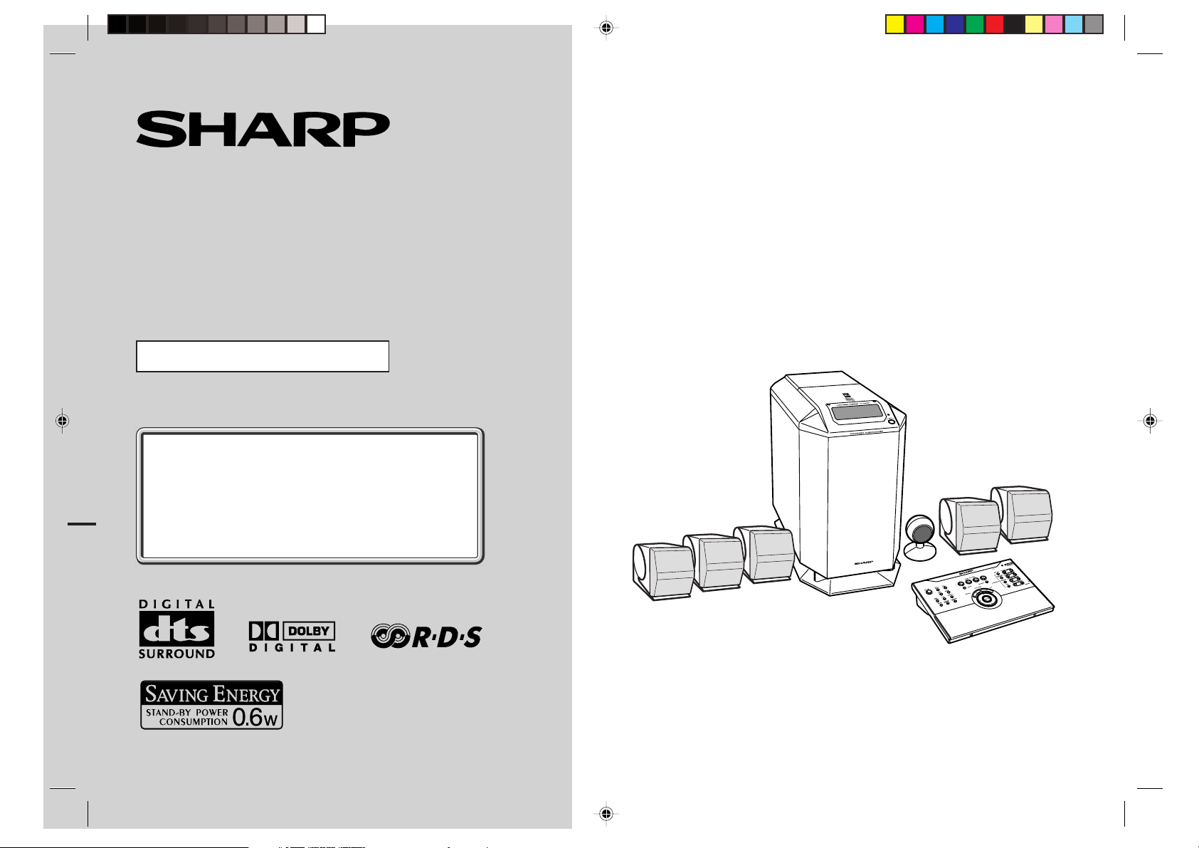
HOME CINEMA COMMAND
MODEL
HT-CN300H
OPERATION MANUAL
If you require any advice or assistance regarding
your Sharp product, please visit our web-site
www.sharp.co.uk/support.
Customers without Internet access may telephone
08705 274277 during office hours (or (01) 676 0648
if telephoning from Ireland).
Thank you for purchasing this SHARP product. To obtain the best
performance from this product, please read this manual carefully.
It will guide you in operating your SHARP product.
HT-CN300H Home Cinema Command consisting of HT-CN300H (main
unit), CP-CN300HF (front speakers), CP-CN300HC (center speaker)
and CP-CN300HR (surround speakers).
0101
Page 2
HT-CN300H
Special Notes
NOTES FOR USERS IN THE U.K. AND IRELAND
The mains lead of this product is fitted with a non-rewireable (moulded) plug incorporating a 3A fuse. Should the fuse need to be replaced, a BSI or ASTA approved BS
1362 fuse marked or and of the same rating as above, which is also indicated on
the pin face of the plug must be used.
Always refit the fuse cover after replacing the fuse. Never use the plug without the
fuse cover fitted.
In the unlikely event of the socket outlet in your home not being compatible with the
plug supplied, cut-off the mains plug and fit an appropriate type.
DANGER:
The fuse from the cut-off plug should be removed and the cut-off plug destroyed
immediately and disposed of in a safe manner.
Under no circumstances should the cut-off plug be inserted elsewhere into a 13A
socket outlet as a serious electric shock may occur.
To fit an appropriate plug to the mains lead, follow the instructions below:
IMPORTANT:
The wires in the mains lead are coloured in accordance with the following code:
Blue : Neutral
Brown : Live
As the colours of the wires in the mains lead of this product may not correspond with
the coloured markings identifying the terminals in your plug, proceed as follows:
● The wire which is coloured blue must be connected to the plug terminal which is
marked N or coloured black.
● The wire which is coloured brown must be connected to the plug terminal which is
marked L or coloured red.
Ensure that neither the brown nor the blue wire is connected to the earth terminal in
your three pin plug.
- Special Notes -
Before replacing the plug cover, make sure that:
● If the new fitted plug contains a fuse, its value is the same as that removed from
the cut-off plug.
● The cord grip is clamped over the sheath of the mains lead and not simply over the
lead wires.
Important Instruction
IF YOU HAVE ANY DOUBT, CONSULT A QUALIFIED ELECTRICIAN.
SERVICE INFORMATION
In the unlikely event of your equipment requiring repair, please contact the dealer or
supplier from whom it was purchased. Where this is not possible, please visit our
web-site www.sharp.co.uk/support.
Customers without internet access may telephone 08705 274277 during office hours
(or (01) 676 0648 if telephoning from Ireland).
Please note; all calls will be charged at local rate.
Certain replacement parts and accessories may be obtained from our main parts
distributor.
In the unlikely event of this equipment requiring repair during the guarantee period,
you will need to provide proof of the date of purchase to the repairing company.
Please keep your invoice or receipt, which is supplied at the time of purchase.
WILLOW VALE ELECTRONICS LTD.
0121 766 5414
WARNINGS
z
When the ON/STAND-BY button is set at STAND-BY position, mains voltage is still
present inside the unit. When the ON/STAND-BY button is set at STAND-BY position, the unit may be brought into operation by the timer mode or remote control.
z
This unit contains no user serviceable parts. Never remove covers unless qualified
to do so. This unit contains dangerous voltages, always remove mains plug from
the socket before any service operation and when not in use for a long period.
z
The supplied AC adaptor contains no user serviceable parts. Never remove covers
unless qualified to do so. It contains dangerous voltages, always remove mains
plug from the main outlet socket before any service operation or when not in use
for a long period.
z
To prevent fire or shock hazard, do not expose this appliance to dripping or splashing. No objects filled with liquids, such as vases, should be placed on the apparatus.
NOTES
z
This equipment complies with the requirements of Directives 89/336/EEC and 73/
23/EEC as amended by 93/68/EEC.
z
The letters in brackets contained in the model number indicate the colour of the
product only. Operation and specifications are unaffected.
2
HT-CN300H_(E)1.fm02/6/17
Page 3

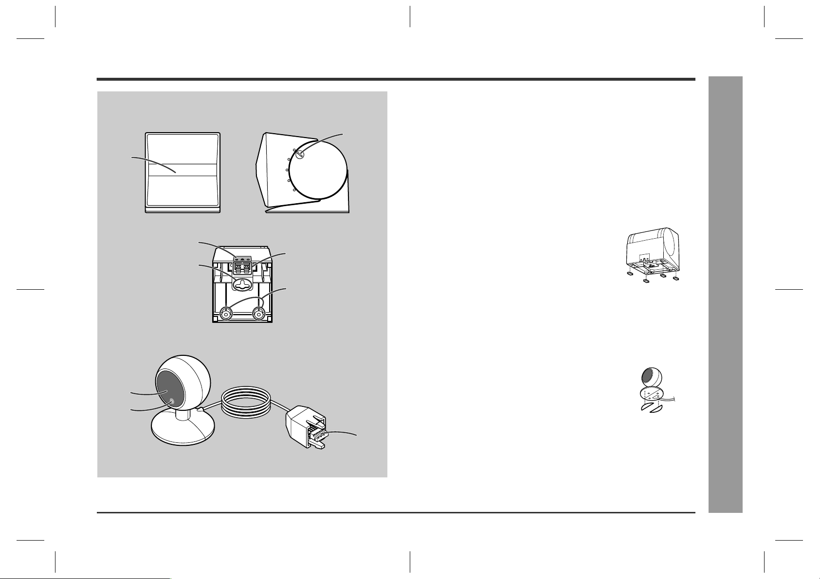
Accessories
Contents
HT-CN300H
Please confirm that the following accessories are included.
Remote control 1
AM loop aerial 1 Remote control
Video cable 1
AC adaptor for
remote control 1
(RADPA8005BGZZ)
sensor 1
Front (left):
5 m (15')
Labels for remote
control 1
Double-sided tape
for remote control
sensor 1
Green
Centre:
5 m (15')
FM aerial 1
IN
OUT
SCART adaptor 2
(IN/OUT)
RedWhite
Front (right):
5 m (15')
Page
General Information
Precautions . . . . . . . . . . . . . . . . . . . . . . . . . . . . . . . . . . . . . . . . . . . . . . . . . . . . . . .4
Controls and indicators . . . . . . . . . . . . . . . . . . . . . . . . . . . . . . . . . . . . . . . . . . 5 - 7
Connections
Speaker connections . . . . . . . . . . . . . . . . . . . . . . . . . . . . . . . . . . . . . . . . . . . . .8, 9
Remote control sensor connection . . . . . . . . . . . . . . . . . . . . . . . . . . . . . . . . . . . .9
Aerial connection . . . . . . . . . . . . . . . . . . . . . . . . . . . . . . . . . . . . . . . . . . . . . . . . . .9
Connecting other equipment . . . . . . . . . . . . . . . . . . . . . . . . . . . . . . . . . . . . 10 - 12
Connecting to the AC socket . . . . . . . . . . . . . . . . . . . . . . . . . . . . . . . . . . . . . . . .13
Speaker Installation
Placing the speaker system . . . . . . . . . . . . . . . . . . . . . . . . . . . . . . . . . . . . . . . . .14
Installing the speakers on the wall . . . . . . . . . . . . . . . . . . . . . . . . . . . . . . . . . . . 15
Remote Control
Preparing the remote control . . . . . . . . . . . . . . . . . . . . . . . . . . . . . . . . . . . . . . . .16
Operation buttons on the remote control . . . . . . . . . . . . . . . . . . . . . . . . . . 17 - 19
Memorising the remote control buttons . . . . . . . . . . . . . . . . . . . . . . . . . . . .20, 21
Basic Operation
Setting the clock . . . . . . . . . . . . . . . . . . . . . . . . . . . . . . . . . . . . . . . . . . . . . . . . . .22
Display control . . . . . . . . . . . . . . . . . . . . . . . . . . . . . . . . . . . . . . . . . . . . . . . . . . . . 23
Sound control . . . . . . . . . . . . . . . . . . . . . . . . . . . . . . . . . . . . . . . . . . . . . . . . . . . .23
Enjoy Surround Sound (sound mode) . . . . . . . . . . . . . . . . . . . . . . . . . . . . . 24 - 26
Listening to the radio . . . . . . . . . . . . . . . . . . . . . . . . . . . . . . . . . . . . . . . . . . . . . . 27
Listening to a memorised station . . . . . . . . . . . . . . . . . . . . . . . . . . . . . . . . . . . .28
- Accessories / Contents -
General Information
Blue Grey
Surround (left):
15 m (45')
Speaker cushion
20
Note:
Only the above accessories are included.
Speaker connection lead 5
Surround (right):
15 m (45')
Advanced Features
Using the Radio Data System (RDS) . . . . . . . . . . . . . . . . . . . . . . . . . . . . . . 29 - 34
Speaker settings . . . . . . . . . . . . . . . . . . . . . . . . . . . . . . . . . . . . . . . . . . . . . . 35 - 37
Timer and sleep operation . . . . . . . . . . . . . . . . . . . . . . . . . . . . . . . . . . . . . . . 38, 39
References
Troubleshooting chart . . . . . . . . . . . . . . . . . . . . . . . . . . . . . . . . . . . . . . . . . . .40, 41
Error indicators and warnings . . . . . . . . . . . . . . . . . . . . . . . . . . . . . . . . . . . . . . . 42
Maintenance . . . . . . . . . . . . . . . . . . . . . . . . . . . . . . . . . . . . . . . . . . . . . . . . . . . . . .42
Specifications . . . . . . . . . . . . . . . . . . . . . . . . . . . . . . . . . . . . . . . . . . . . . . . . .42, 43
TERMS OF GUARANTEE . . . . . . . . . . . . . . . . . . . . . . . . . . . . . . . . . . . . Back cover
HT-CN300H_(E)1.fm02/6/17
3
Page 4

HT-CN300H
Precautions
General
z
Please ensure that the equipment is positioned in a well ventilated area and that
there is at least 10 cm (4") of free space along the sides and back. There must
also be a minimum of 15 cm (6") of free space on the top of the unit.
z
Hold the AC power plug by the head when removing
it from the wall socket, as pulling the lead can damage internal wires.
General Information
10 cm (4") 10 cm (4")
z
Use the unit on a firm, level surface free from vibration.
z
Keep the unit away from direct sunlight, strong magnetic fields, excessive dust, humidity and electronic/
electrical equipment (home computers, facsimiles,
etc.) which generates electrical noise.
- Precautions -
z
Do not place anything on top of the unit.
z
Do not expose the unit to moisture, to temperatures higher than 60°C (140°F) or to
extremely low temperatures.
z
If your system does not work properly, disconnect the AC power lead from the wall
socket. Plug the AC power lead back in, and then turn on your system.
z
In case of an electrical storm, unplug the unit for
safety.
15 cm (6")
10 cm (4")
z
Do not remove the outer cover, as this may result
in electric shock. Refer internal service to your
local SHARP service facility.
z
The ventilation should not be impeded by covering
the ventilation openings with items, such as newspapers, tablecloths, curtains, etc.
z
No naked flame sources, such as lighted candles, should be placed on the apparatus.
z
Attention should be drawn to the environmental aspects of battery disposal.
z
The apparatus is designed for use in moderate climate.
z
This unit should only be used within the range of 5°C - 35°C (41°F - 95°F).
z
When carrying the unit by hand, do not hold the subwoofer located on the lower
part. The subwoofer may be damaged.
Correct
Warning:
The voltage used must be the same as that specified on this unit. Using this product
with a higher voltage other than that which is specified is dangerous and may result in
a fire or other type of accident causing damage. SHARP will not be held responsible
for any damage resulting from use of this unit with a voltage other than that which is
specified.
Volume control
The sound level at a given volume setting depends on speaker efficiency, location,
and various other factors. It is advisable to avoid exposure to high volume levels, to
avoid this do not turn the volume on to full at switch on and listen to music at moderate levels.
4
HT-CN300H_(E)1.fm02/6/17
Page 5
Controls and indicators
10
11
12
13
14
15
16
17
18
1
2456
26
3
27
78 9
29
28
19
20
21
22
23
24
25
17
18
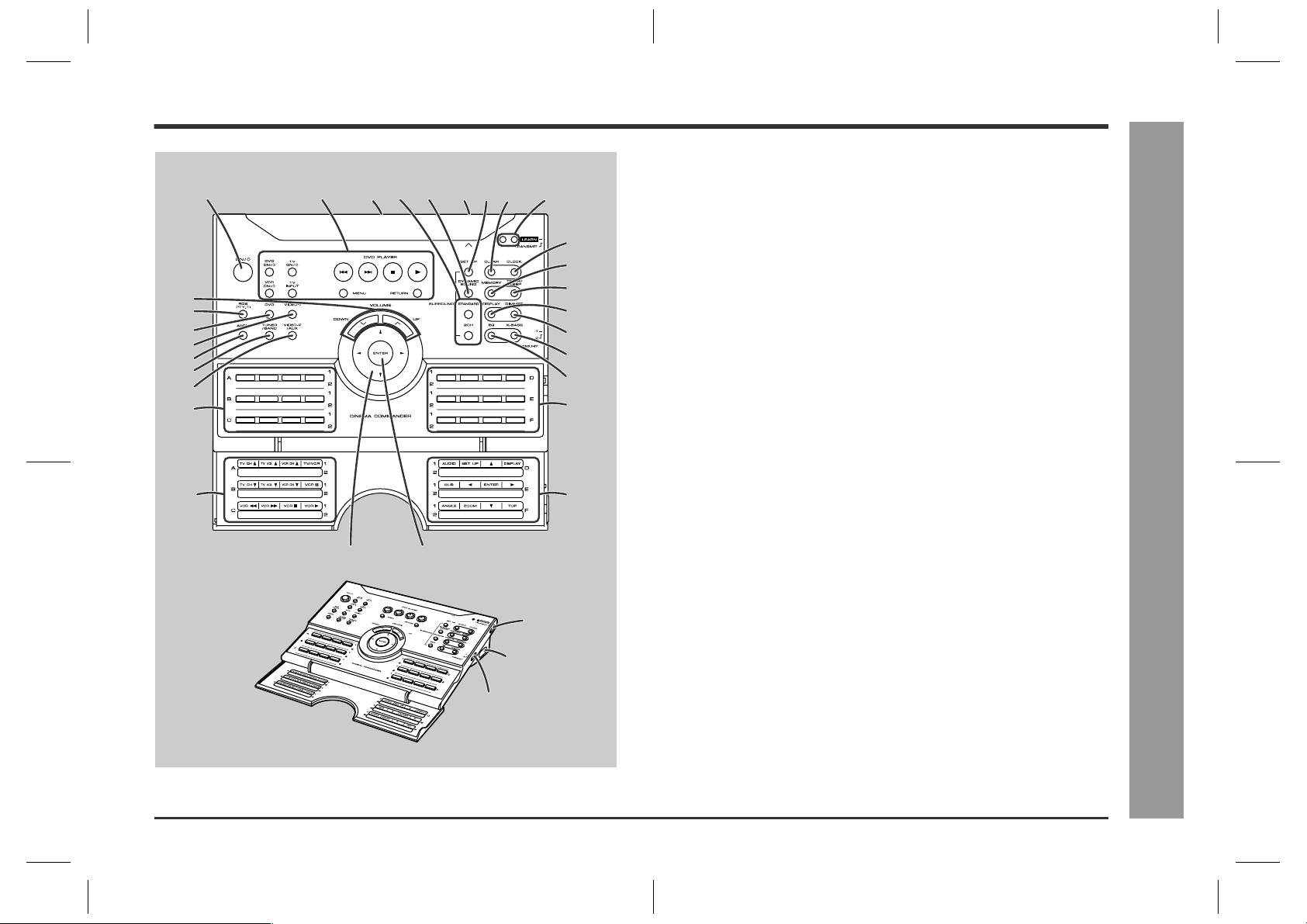
Remote control
1. On/Stand-by Button . . . . . . . . . . . . . . . . . . . . . . . . . . . . . . . . . . . . . 13
2. Operation Buttons for Other Equipment . . . . . . . . . . . . . . . . . . . . . 18
3. Remote Control Transmitter . . . . . . . . . . . . . . . . . . . . . . . . . . . . . . . 16
4. Sound Mode Select Buttons . . . . . . . . . . . . . . . . . . . . . . . . . . . . . . 26
5. Dynamic Sound Select Button . . . . . . . . . . . . . . . . . . . . . . . . . . . . . 26
6. Remote Control Sensor for Learn Function . . . . . . . . . . . . . . . . . . 20
7. Speaker Set Up Button . . . . . . . . . . . . . . . . . . . . . . . . . . . . . . . . . . . 35
8. Clear Button . . . . . . . . . . . . . . . . . . . . . . . . . . . . . . . . . . . . . . . . . 21, 28
9. Learn Indicators . . . . . . . . . . . . . . . . . . . . . . . . . . . . . . . . . . . . . . . . 20
10.Volume Up and Down Buttons . . . . . . . . . . . . . . . . . . . . . . . . . . . . . 23
11.RDS Programme Type/Traffic Information Search Button . . . . . . . 32
12.DVD Button . . . . . . . . . . . . . . . . . . . . . . . . . . . . . . . . . . . . . . . . . . . . 18
13.Video-1 Button . . . . . . . . . . . . . . . . . . . . . . . . . . . . . . . . . . . . . . . . . . 18
14.RDS ASPM (Auto Station Programme Memory) Button . . . . . . . . 31
15.Tuner/Band Button . . . . . . . . . . . . . . . . . . . . . . . . . . . . . . . . . . . . . . 27
16.Video-2/Auxiliary Button . . . . . . . . . . . . . . . . . . . . . . . . . . . . . . . . . 18
17.Memory 1/2 Buttons for Other Equipment . . . . . . . . . . . . . . . . . . . 19
18.Label Sealing Area . . . . . . . . . . . . . . . . . . . . . . . . . . . . . . . . . . . . . . 21
19.Clock Button . . . . . . . . . . . . . . . . . . . . . . . . . . . . . . . . . . . . . . . . 22, 34
20.Memory Button . . . . . . . . . . . . . . . . . . . . . . . . . . . . . . . . . . . . . . . . . 28
21.Timer/Sleep Button . . . . . . . . . . . . . . . . . . . . . . . . . . . . . . . . . . . . . . 38
22.TV Screen Display/RDS Display Mode Selector Button . . 23, 29, 34
23.Dimmer Button . . . . . . . . . . . . . . . . . . . . . . . . . . . . . . . . . . . . . . . . . 23
24.Extra Bass/Demo Mode Button . . . . . . . . . . . . . . . . . . . . . . . . . 13, 23
25.Equaliser Mode Selector Button . . . . . . . . . . . . . . . . . . . . . . . . . . . 23
26.Cursor Button . . . . . . . . . . . . . . . . . . . . . . . . . . . . . . . . . 22, 27, 35, 38
27.Enter Button . . . . . . . . . . . . . . . . . . . . . . . . . . . . . . . . . . . . . 22, 35, 38
28.Learn/Transmit Selector Switch . . . . . . . . . . . . . . . . . . . . . . . . . . . . 20
29.3.6 V DC Input Socket . . . . . . . . . . . . . . . . . . . . . . . . . . . . . . . . . . . . 13
30.Memory 1/2 Selector Switch . . . . . . . . . . . . . . . . . . . . . . . . . . . . 19, 20
Reference page
HT-CN300H
- Controls and indicators -
General Information
30
5
HT-CN300H_(E)1.fm02/6/17
Page 6
HT-CN300H
General Information
Controls and indicators (continued)
12 345867
9
10
11 12 13 14
Back
18
19
20
- Controls and indicators -
21
22
23
15
Front
25
26
27
28
29
30
31
16
17
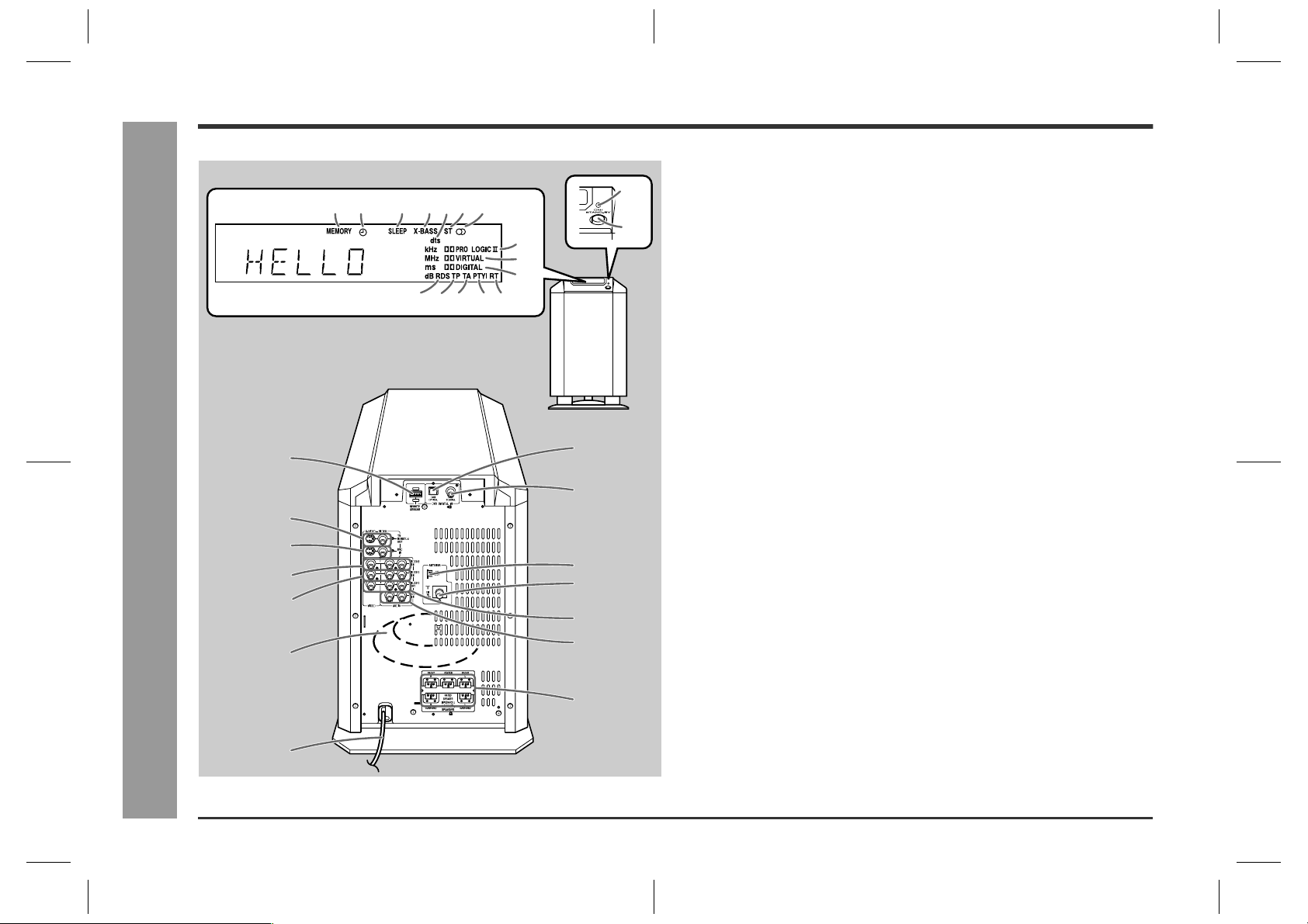
Main unit (with subwoofer)
1. Memory Indicator
2. Timer Play Indicator
3. Sleep Indicator
4. Extra Bass Indicator
5. Digital Theatre System Indicator
6. FM Stereo Mode Indicator
7. FM Stereo Receiving Indicator
8. Dolby Pro Logic II Indicator
9. Dolby Virtual Indicator
10.Dolby Digital Indicator
11.RDS Indicator
12.Traffic Programme Indicator
13.Traffic Announcement Indicator
14.Dynamic PTY Indicator
15.Radio Text Indicator
16.Power Indicator . . . . . . . . . . . . . . . . . . . . . . . . . . . . . . . . . . . . . . . . .13
17.On/Stand-by Button . . . . . . . . . . . . . . . . . . . . . . . . . . . . . . . . . . . . . .13
18.Remote Control Sensor Socket . . . . . . . . . . . . . . . . . . . . . . . . . . . . .9
19.TV Monitor Output Sockets . . . . . . . . . . . . . . . . . . . . . . . . . . . . . . . .11
20.DVD Video Input Sockets . . . . . . . . . . . . . . . . . . . . . . . . . . . . . . . . .11
21.Video and Audio Input Sockets (VIDEO 2) . . . . . . . . . . . . . . . . . . .12
22.Video and Audio Input Sockets (VIDEO 1) . . . . . . . . . . . . . . . . . . .12
23.Subwoofer
24.AC Power Lead . . . . . . . . . . . . . . . . . . . . . . . . . . . . . . . . . . . . . . . . . .13
25.DVD Optical Digital Audio Input Socket . . . . . . . . . . . . . . . . . . . . . .11
26.DVD Coaxial Digital Audio Input Socket . . . . . . . . . . . . . . . . . . . . .11
27.AM Loop Aerial Socket . . . . . . . . . . . . . . . . . . . . . . . . . . . . . . . . . . . .9
28.FM 75 Ohms Aerial Socket . . . . . . . . . . . . . . . . . . . . . . . . . . . . . . . . .9
29.Video and Audio Output Sockets (VIDEO 1) . . . . . . . . . . . . . . . . . .12
30.Auxiliary Audio Input Sockets . . . . . . . . . . . . . . . . . . . . . . . . . . . . .12
31.Speaker Terminals . . . . . . . . . . . . . . . . . . . . . . . . . . . . . . . . . . . . . . . .8
Reference page
24
6
HT-CN300H_(E)1.fm02/6/17
Page 7
Front/Centre/Surround speakers
1. Full-Range Speaker
Front Side
2
1
3
Bottom
2. Angle Adjusting Lever . . . . . . . . . . . . . . . . . . . . . . . . . . . . . . . . . . . 15
3. Label indication
Front Speaker (right): Red
Front Speaker (left): White
Centre Speaker: Green
Surround Speaker (right): Grey
Surround Speaker (left): Blue
4. Mounting Slot . . . . . . . . . . . . . . . . . . . . . . . . . . . . . . . . . . . . . . . . . . 15
5. Speaker Terminals . . . . . . . . . . . . . . . . . . . . . . . . . . . . . . . . . . . . . . . 8
6. Mounting Screw Holes . . . . . . . . . . . . . . . . . . . . . . . . . . . . . . . . . . . 15
Speaker cushion:
Attach the cushions to the bottom of the speakers to prevent
them from sliding.
Reference page
HT-CN300H
5
4
6
Remote control sensor
1. Remote Sensor . . . . . . . . . . . . . . . . . . . . . . . . . . . . . . . . . . . . . . . . . 16
2. Remote Control Indicator . . . . . . . . . . . . . . . . . . . . . . . . . . . . . . . . . 16
3. Remote Sensor Connection Plug . . . . . . . . . . . . . . . . . . . . . . . . . . . 9
Double-sided tape for remote control sensor:
You can fix the remote control sensor with the supplied tape.
Reference page
- Controls and indicators -
General Information
1
2
Caution:
z
3
Carefully choose where you place the remote control sensor as the adhesive tape
may damage or peel the surface coating when the tape is removed.
z
Never locate the remote control sensor in an unstable place. Otherwise it may fall.
Note:
Fix the remote control sensor on a flat surface.
7
HT-CN300H_(E)1.fm02/6/17
Page 8
HT-CN300H
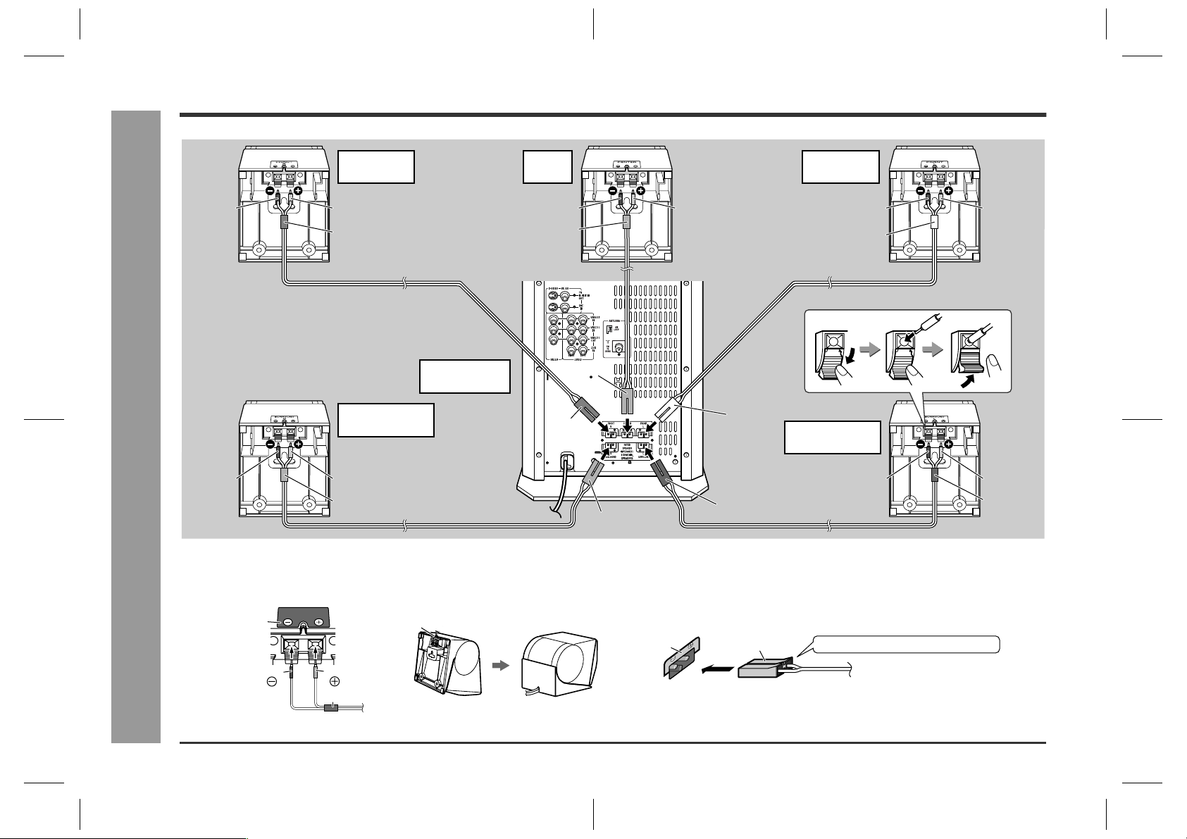
Speaker connections
Connections
Front speaker
(right)
Black
Black
- Speaker connections -
The speaker terminals on the main unit, the tube and plugs of the speaker lead, and speaker labels are distinguished by colour.
Connect the speaker and the unit by matching the colours.
Connect the speaker wires to the speakers first, then to the unit.
Red
Red
Main unit
(with subwoofer)
Surround speaker
(right)
Red
Grey
Centre
speaker
Black
Green
Red
Red
Green
White
Blue
Grey
Speaker Main unit
Front speaker
(left)
Black
White
Surround speaker
(left)
Black
Red
Red
Blue
Label
Black
Red
Tube
Recess
Label
Speaker plug
Plug in with the rising side facing up.
8
HT-CN300H_(E)2.fm02/6/17
Page 9
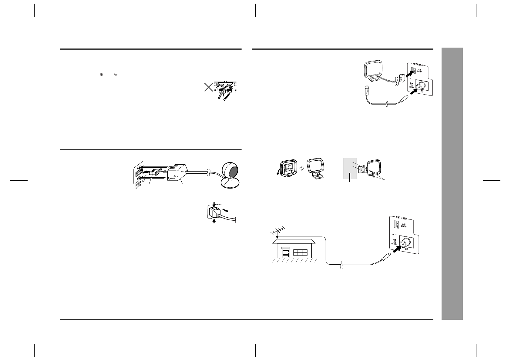
Aerial connection
HT-CN300H
Caution:
z
Only the supplied speakers should be used with this unit.
z
Make sure to connect the speakers after unplugging the unit.
z
Do not mistake and , and right and left terminals of the speaker leads.
z
Do not let the bare speaker wires touch each other.
z
Do not stand or sit on the speakers. You may be injured.
z
Insert the speaker plug fully with the rising side facing up.
z
Hold the speaker plug when removing it from the unit. Pulling
the lead may cause breakage.
Remote control sensor connection
Connect the plug of the remote
control sensor and push the plug
cover until it clicks.
Plug
Removing the remote control sensor:
Push the upper and lower sides of the plug cover and take the
plug off the unit to disconnect the remote control sensor.
Caution:
z
Hold the connection plug of the remote control sensor when removing it from the
unit. Pulling the lead may cause breakage.
z
Make sure of the top and bottom of the plug when plugging in the remote control
sensor.
Plug cover
Push
Push
Supplied FM aerial:
Connect the FM aerial wire to the FM 75 OHMS
socket and position the FM aerial wire in the direction where the strongest signal can be received.
Supplied AM loop aerial:
Connect the AM loop aerial to the AM LOOP socket. Position the AM loop aerial for optimum reception. Place the AM loop aerial on a shelf, etc., or
attach it to a stand or a wall with screws (not supplied).
Note:
Placing the aerial on the unit, or near the AC power lead or the remote sensor may
cause noise pickup. Place the aerial away from the unit for better reception.
Installing the AM loop aerial:
< Assembling > < Attaching to the wall >
Wall
External FM aerial:
Use an external FM aerial if you require better reception. Consult your dealer.
External FM aerial
Screws
(not supplied)
Connections
- Speaker / Remote control sensor / Aerial connections -
9
HT-CN300H_(E)2.fm02/6/17
Page 10
HT-CN300H
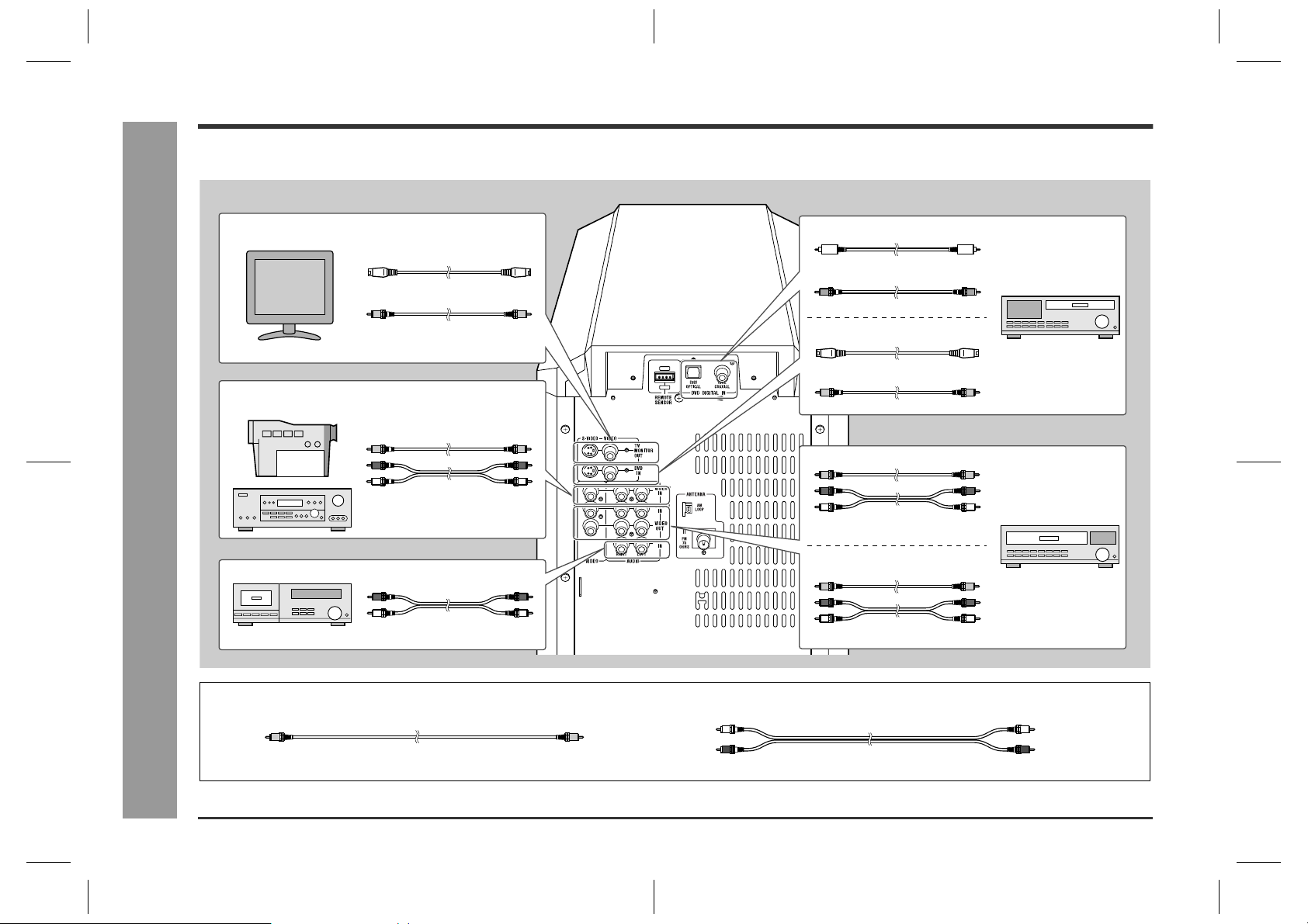
Connecting other equipment
To enjoy images or music, connect other equipment to the main unit with the supplied video cable for TV or you can purchase commercially available cables.
One video cable and two SCART adaptors are supplied.
Connections
- Connecting other equipment -
TV
Camcorder,
Satellite receiver, etc.
Tape deck, etc.
S-video cable
Video cable (supplied)
(See page 11.)
Video cable
Audio cable
(See page 12.)
Audio cable
(See page 12.)
Optical digital audio cable
or
Coaxial digital audio cable
S-video cable
Video cable
Video cable
Audio cable
Video cable
Audio cable
DVD player
(See page 11.)
VCR
(See page 12.)
10
Video cable:
Yellow Yellow
Audio cable:
White (Left)
Red (Right)
White (Left)
Red (Right)
HT-CN300H_(E)2.fm02/6/17
Page 11
Caution:
Turn off all other equipment before making this connection.
Notes:
z
Refer to the operation manual of the equipment to be connected.
z
Insert the plugs fully to avoid fuzzy pictures or noise.
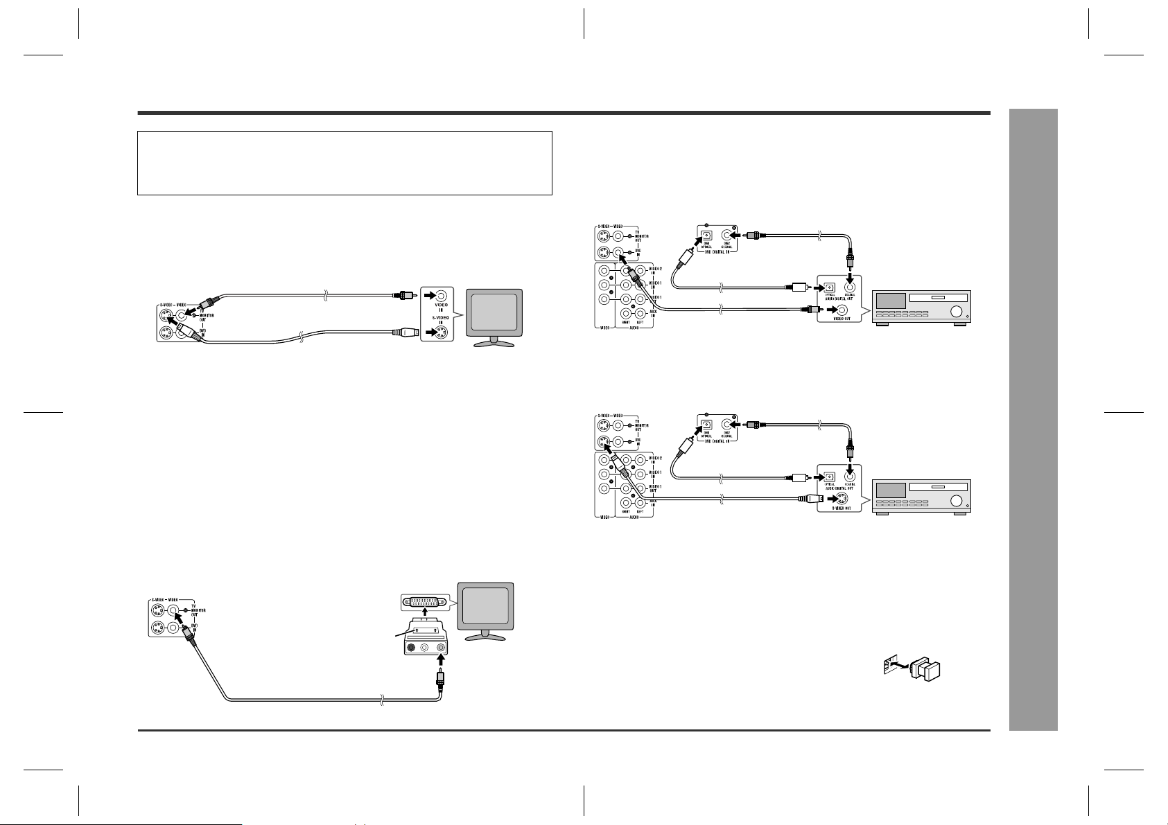
Connecting the TV
Connect the TV to the main unit with the supplied video cable. If your TV has S-video
input socket, connect the commercially available S-video cable to enjoy clearer
images on DVDs.
Video cable (supplied)
To video input socket
TV
Connecting the DVD player
Use the video cable or the S-video cable for receiving images. The S-video cable can
realise clearer images. For audio, connect with the optical digital cable or the coaxial
digital cable.
To connect to the video socket with the video cable:
Coaxial digital
audio cable
Optical digital audio cable
DVD player
HT-CN300H
S-video cable
To S-video input socket
Notes:
z
Change the TV input in accordance with the connected socket.
z
Do not connect other equipment between the TV and this unit. If they are connected via a VCR, pictures may be distorted.
z
When the video and S-video cables are both connected, the images from the Svideo input socket appears on your TV.
Caution:
The settings appear only when the TV is connected with a video cable. They
will not appear when the TV is connected with an S-video cable.
During the tuner or auxiliary mode, the TV screen display will not be shown.
(See page 23 for the TV screen display.)
Connecting the TV with SCART socket:
Use a supplied SCART adaptor (IN).
TV
To SCART
socket
IN
SCART adaptor (IN)
To video input socket
Video cable (supplied)
LAUDIO VIDEOR
Video cable
To video output socket
Note:
When connecting a DVD player with a video cable, be sure to use another video
cable for the TV.
To connect to the S-video socket with the S-video cable:
Coaxial digital
audio cable
Optical digital audio cable
S-video cable
To S-video output socket
DVD player
Note:
When connecting a DVD player with an S-video cable, be sure to use another S-video
cable for the TV. This unit cannot convert the S-video signal into the video or other
signals.
Switching the DVD audio input:
Switch the DVD's audio signal with the remote control according to the connected
socket, "DIG1" (optical) or "DIG2" (coaxial) (see page 18).
Optical digital socket cap:
When using the optical digital socket, remove the cap
first. After using the socket, replace the cap.
Connections
- Connecting other equipment -
11
HT-CN300H_(E)2.fm02/6/17
Page 12
HT-CN300H
Connecting other equipment (continued)
Connections
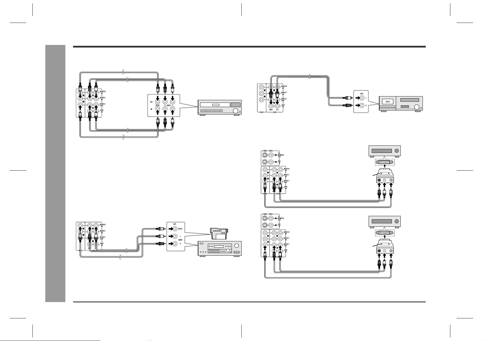
Connecting the VCR (VIDEO 1)
Video cable
Audio cable
Audio cable
Video cable
To video
output socket
To video
input socket
To audio
output sockets
VCR
To audio
input sockets
Notes:
z
Connect the unit and the TV with a video cable. The image of the equipment connected to the VIDEO 1 IN sockets does not appear on the TV even if it is connected with an S-video cable.
z
The image and sound are not emitted from the VIDEO 1 OUT sockets when the
equipment is connected to the DVD or VIDEO 1 IN sockets.
If connected to the VIDEO 2 IN sockets, they are emitted from the VIDEO 1 OUT
sockets. If connected to the AUX IN sockets or whilst in the tuner mode, only the
sound is emitted.
Connecting the camcorder, satellite
receiver, etc. (VIDEO 2)
- Connecting other equipment -
Audio cable
Video cable
Note:
Connect the unit and the TV with a video cable. The image of the equipment connected to the VIDEO 2 IN sockets does not appear on the TV even if it is connected
with an S-video cable.
To video
output socket
To audio
output sockets
Camcorder,
Satellite receiver, etc.
Connecting the tape deck, etc. (AUX)
Audio cable
To audio output sockets
Tape deck, etc.
Connection example using a SCART adap-
tor
To SCART
socket
OUT
LAUDIO VIDEOR
IN
LAUDIO VIDEOR
To video
output socket
To video
input socket
Audio cable
Video cable
Audio cable
Video cable
SCART adaptor (OUT)
To audio
output sockets
To SCART
socket
SCART adaptor (IN)
To audio
input sockets
12
HT-CN300H_(E)2.fm02/6/17
Page 13
Connecting to the AC socket
HT-CN300H
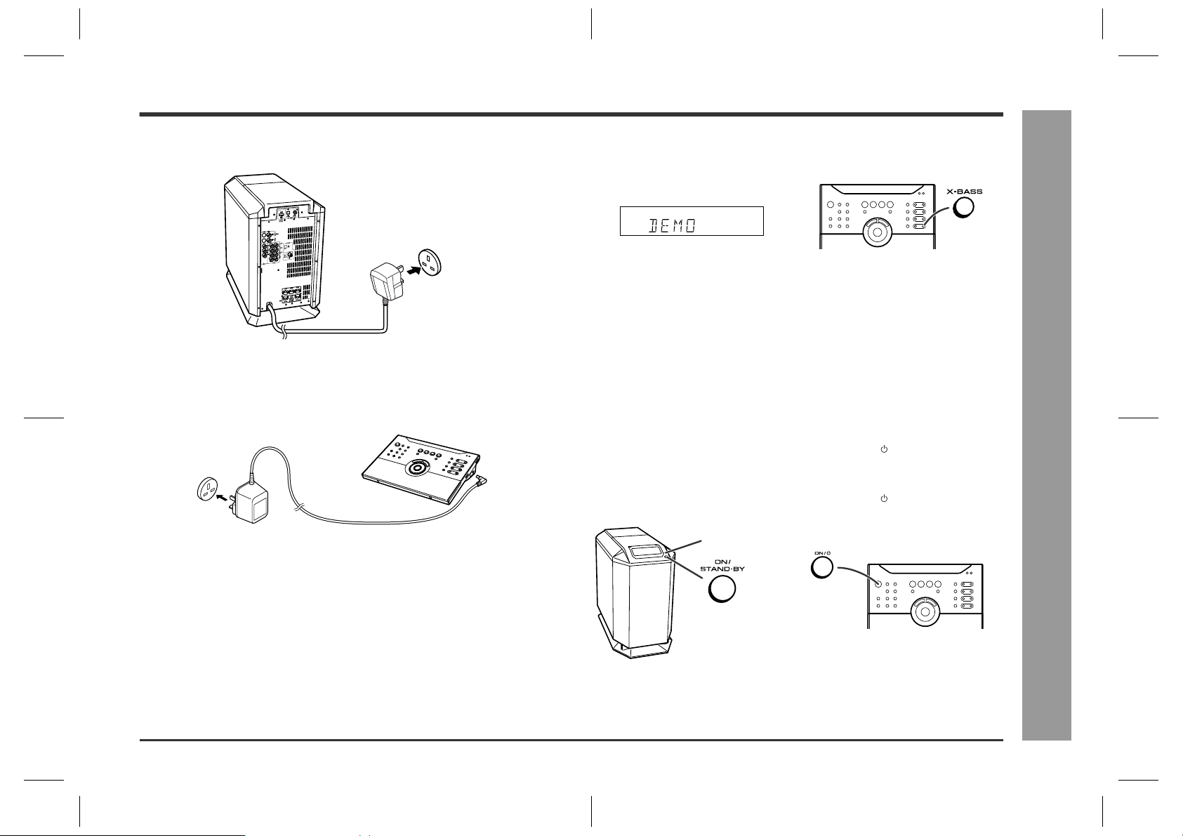
Plugging in the main unit
After all connections are made, plug in the unit.
Wall socket
(AC 230 V, 50 Hz)
Note:
Unplug the AC power lead from the wall socket if the unit will not be in use for a prolonged period of time.
Plugging in the remote control
Wall socket
(AC 230 V, 50 Hz)
Notes:
z
You can operate the remote control with batteries (not supplied) in areas where
the AC adaptor lead cannot reach (see page 16).
z
Remove the AC adaptor from the AC socket if the unit will not be in use for a prolonged period of time.
z
Use only the supplied AC adaptor. Another adaptor may cause an electric shock or
fire.
z
If it is necessary to replace the AC adaptor, replace it with the same type
(RADPA8005BGZZ) which is shown on page 3.
To 3.6 V DC
input socket
Demonstration mode
The first time the unit is plugged in, the unit will enter the demonstration mode. You
will see words scroll.
To cancel the demonstration mode:
When the unit is in the power stand-by mode (demonstration mode), press the XBASS button. The demonstration mode will be cancelled and the display will disappear.
To return to the demonstration mode:
When the unit is in the power stand-by mode, press the X-BASS button again.
Note:
When the power is on, the X-BASS button can be used to select the extra bass mode
(see page 23).
To turn the power on
Press the ON/STAND-BY button on the main unit or the ON/ (STAND-BY) button on
the remote control.
To set the unit to stand-by mode:
Press the ON/STAND-BY button on the main unit or the ON/ (STAND-BY) button on
the remote control again.
Power indicator
Connections
- Connecting to the AC socket -
Notes:
z
For the operation range and direction of the remote control, see page 16.
z
When turning on the power right after it is set to the stand-by mode, wait a few
seconds.
HT-CN300H_(E)3.fm02/6/17
13
Page 14
HT-CN300H
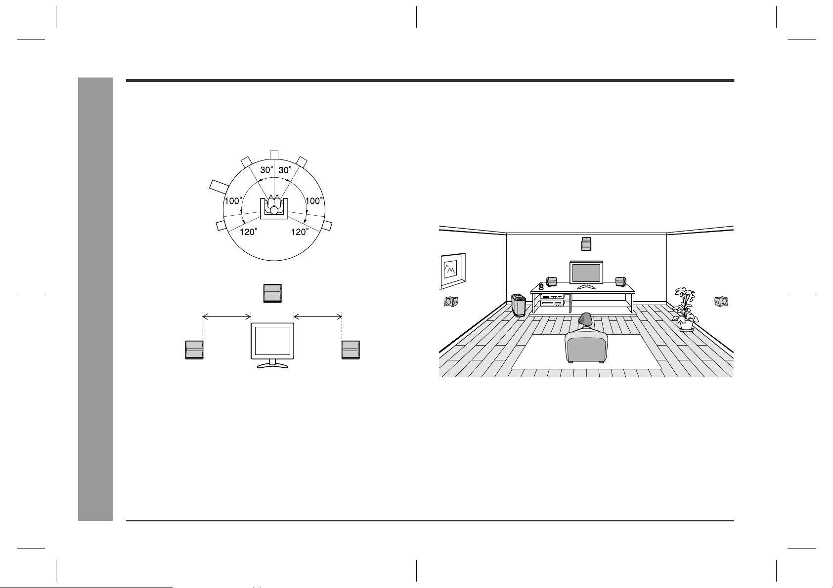
Placing the speaker system
- Placing the speaker system -
Speaker Installation
The best surround effect will be achieved by placing each speaker at the same distance from the listening position.
It is recommended to arrange the speakers as shown below.
Centre
Front
speaker (left)
Main unit
(subwoofer)
Surround
speaker (left)
Same distance
Front speaker (left)
speaker
Front
speaker (right)
Surround
speaker (right)
Centre speaker
Same distance
Front speaker (right)
Notes:
z
Place the TV halfway between the front speakers.
z
It is recommended that the centre speaker be placed near the television.
z
Place the surround speakers at a position just above the height of your ears.
The supplied speakers may be placed beside or near the TV as they are magnetically
shielded. However, colour variation may occur, depending on the type of the TV.
If colour variation occurs...
Turn off the TV (from the power switch).
After 15 - 30 minutes, turn the TV on again.
If the colour variation is still present...
Move the speakers further away from the TV.
Refer to the user's manual of the TV for details.
Example of speaker locations:
14
HT-CN300H_(E)3.fm02/6/17
Page 15

Installing the speakers on the wall
Mark
HT-CN300H
Front, centre and surround speakers can be mounted on the wall and their angle can
be adjusted. Each speaker needs 3 screws to be mounted (not supplied).
The design of the speakers allows them to
be hung on the wall.
Be sure to use the type and size of the
screw that are shown.
Make a hole in the wall using a
1
drill.
Drive a wall mount plug into the
2
hole using a hammer. Drive the
wall mount plug in until it is
flush with the wall surface.
Drive one screw into the wall
3
mount plug for each speaker.
z
Make sure that both the screw and the wall can support a load of 20 kg (45 lbs.).
z
Drive the screw, so the screw head extends about 3.5 mm (9/64") out from the
wall.
Install the speaker on the wall by inserting the screw head into the
4
slot on the back of the speaker.
Wall surface
5 mm
(3/16")
Min. 22 mm (7/8")
8 - 9 mm (3/8")
Wall surface
Recess
3.2 mm (1/8")
9 mm (3/8")
32 mm (1-1/4")
Wall mounting screw
Raise the speaker the most upward. (Refer to "Changing the speak-
5
er angle" for details.)
Drive two screws into the wall.
6
Label
Use the round labels for hiding mounting screws.
Perform steps 1 - 6 to mount other speakers.
7
Changing the speaker angle:
Whilst holding down the angle adjusting lever, move the speaker to the marking and
then release the lever.
The speaker angle can be adjusted in 5 levels.
Caution:
Check the stability of the ceiling or wall fully. Sharp is not liable for accidents
caused by insufficient stability of the ceiling or wall, or improper mounting.
The speaker may fall due to unstable mounting.
If you need any assistance, contact the dealer you purchased the system from.
The following may cause personal injury or speaker damage.
Applying any other load to the fittings than the speaker.
Modification or change of the fittings.
Stepping on or hanging from the speakers. Especially pay attention to small children.
Label
Speaker Installation
- Installing the speakers on the wall -
Set the speaker lead in the recess, preventing it from being caught between the
wall and the speaker.
15
HT-CN300H_(E)3.fm02/6/17
Page 16

HT-CN300H
Preparing the remote control
Battery installation
You can operate the remote control with batteries in areas where the AC power lead
cannot reach.
Use 2 "AA" size batteries (UM/SUM-3, R6, HP-7 or similar).
Batteries are not included.
Turn the remote control over and place it on a soft cloth.
1
Open the battery cover.
2
Insert the batteries according to the direction indicated in the bat-
3
tery compartment.
When inserting or removing the batteries, push them towards the battery termi-
nals.
Close the cover.
4
Precautions for battery use:
z
Replace all old batteries with new ones at the same time.
z
Remote Control
Do not mix old and new batteries.
z
Remove the batteries if the unit is not to be used for long periods of time. This will
- Preparing the remote control -
prevent potential damage due to battery leakage.
Test of the remote control
Point the remote control directly at the remote sensor.
The remote control can be used within the range shown below:
z
Press the ON/ (STAND-BY) button. Does the power turn on? Now, you can enjoy
your system.
z
When the signal is received, the remote control indicator will flash. Whilst in the
dimmer mode (page 23), it will not flash or light.
Remote sensor
0.2 m - 6 m
(8" - 20')
15
15
Note:
Exposing the remote sensor to strong light may interfere with operation. Change the
lighting or the direction of the remote control sensor.
How to open the remote control cover
To access the Memory 1/2 buttons, open the remote control cover.
Remote control
indicator
20
20
16
Caution:
z
Do not use rechargeable batteries (nickel-cadmium battery, etc.).
z
Installing the batteries incorrectly may cause the unit to malfunction.
Notes concerning use:
z
Replace the batteries if the operating distance is reduced or if the operation
becomes erratic.
z
Periodically clean the transmitter on the remote control and the remote control
sensor with a soft cloth.
z
Keep the remote control away from moisture, heat, shock, and vibrations.
Note:
You can control the DVD, VCR, etc. with this remote control (see page 19).
HT-CN300H_(E)3.fm02/6/17
Page 17

Operation buttons on the remote control
HT-CN300H
This remote control allows you to operate the main unit and other Sharp equipment.
By memorising remote control operations (learn function), you can operate various
equipment.
Operation buttons for other equipment
(See page 18.)
Operation buttons for the main unit
Memory 1/2 buttons for other equipment
(See page 19.)
Operation buttons for the main unit
132 456 789
10
11
12
13
1614 15 17 2221201918
1 ON/ (STAND-BY)
Sets the power to "ON" or "STAND-BY".
2
Changes the settings of time, tuner, timer/sleep operations, and speakers.
3VOLUME
Decreases the volume.
4VOLUME
Increases the volume.
5 STANDARD
Sets the sound mode to "STANDARD".
6 DYNAMIC SOUND
Switches the dynamic sound.
7SET UP
Changes the speaker setting.
8CLEAR
Deletes the tuner pre-selections.
9CLOCK
Sets or displays the clock time.
10 MEMORY
Presets the tuner.
11 TIMER/SLEEP
Sets the power to "ON" or "STAND-BY" at the desired time.
12 DIMMER
Adjusts the brightness of the main unit display.
13 DISPLAY
Switches the TV display or selects the RDS display mode.
14 ASPM
Searches the new RDS stations.
15 RDS PTY.TI
Searches the specifying programme RDS stations.
16
Changes the settings of tuner and speakers.
17
Changes the settings of time, tuner, timer/sleep operations, and speakers.
18 ENTER
Validates the settings of time, timer/sleep operations, and speakers.
19
Changes the settings of tuner and speakers.
20 2CH
Switches the sound mode to "VIRTUAL" or "STEREO".
21 EQ
Changes the tone setting.
22 X-BASS
Adjusts the bass or activates/deactivates the demonstration mode.
Remote Control
- Operation buttons on the remote control -
17
HT-CN300H_(E)3.fm02/6/17
Page 18

HT-CN300H
Operation buttons on the remote control (continued)
Switching the operation buttons for the
main unit
Operation buttons for other equipment
The remote control is set at the factory to operate the Sharp's DVD, TV and VCR.
To operate Sharp products or other companies' equipment that cannot be controlled
by the default remote control, you can memorise their remote control operations
(learn function) (see page 20).
12 345 6
1234
78
1DVD
Used when the unit is set to DVD. Switch the setting according to the connected
sound source by pressing it repeatedly.
Remote Control
(Optical) (Coaxial)
2 TUNER/BAND
- Operation buttons on the remote control -
Selects the tuner function or switches the frequency band.
3 VIDEO-2/AUX
Selects the "VIDEO-2" or "AUX" mode.
4VIDEO-1
Selects the "VIDEO-1" mode.
1 DVD ON/ (STAND-BY)
Sets the DVD power to "ON" or "STAND-BY".
2 TV ON/ (STAND-BY)
Sets the TV power to "ON" or "STAND-BY".
3
Skips DVD chapters.
4
Skips DVD chapters.
5
Stops the DVD player.
6
Plays back the DVD.
7 VCR ON/ (STAND-BY)
Sets the VCR power to "ON" or "STAND-BY".
8TV INPUT
Switches the TV input.
9MENU
Displays the DVD menu.
10 RETURN
Goes back to the previous screen.
910
18
HT-CN300H_(E)3.fm02/6/17
Page 19

HT-CN300H
Memory 1/2 buttons for other equipment
Memory 1 buttons:
The remote control is set at the factory to operate the Sharp's DVD, TV and VCR.
To operate Sharp products or other companies' equipment that cannot be controlled
by the default remote control, you can memorise their remote control operations
(learn function) (see page 20).
Set the MEMORY 1/2 selector switch to MEMORY 1 to use the Memory 1 buttons.
Memory 2 buttons:
No functions are stored at the factory setting. Memorise the remote control signals
(learn function) of your equipment before use (see page 20).
Set the MEMORY 1/2 selector switch to MEMORY 2 to use the Memory 2 buttons.
OPEN
1
2
3
4
5
6
9
7
8
17
18
23 24
22
2110 11 12
13
14
15
16
19
20
Initial setting for Memory 1 buttons:
1 TV/VCR
Switches the input to TV or VCR.
2 VCR CH
Switches up the VCR channels.
3 TV VOL
Turns up the TV volume.
4TV CH
Switches up the TV channels.
5 TV VOL
Turns down the TV volume.
6TV CH
Switches down the TV channels.
7 VCR CH
Switches down the VCR channels.
8 VCR
Pauses VCR.
9 VCR
Rewinds the VCR rapidly.
10 VCR
Advances the VCR rapidly.
11 VCR
Stops the VCR.
12 VCR
Plays the VCR.
13 AUDIO
Switches the DVD sound.
14 SET UP
Changes the DVD settings.
15
Selects the DVD menu.
16 DISPLAY
Switches the DVD display.
17
Selects the DVD menu.
18 SUB
Switches the subtitle of a DVD.
19 ENTER
Validates the menu.
20
Selects the DVD menu.
21 ANGLE
Switches the angle of the DVD images.
22 ZOOM
Zooms the DVD images.
23
Selects the DVD menu.
24 TOP
Displays the top menu of the DVD.
For details, refer to the operation manual attached to the other equipment.
Remote Control
- Operation buttons on the remote control -
19
HT-CN300H_(E)3.fm02/6/17
Page 20

HT-CN300H
Memorising the remote control buttons
You can assign only one function to each button. If you assign two functions to the
button, the newer one will be memorised (learn function).
Memorising operations in the Memory 2
buttons for other equipment
The same buttons are used for both Memory 1 and 2 operations. To store signals in
Memory 1 buttons, set the MEMORY 1/2 selector switch to MEMORY 1, and for
Memory 2 buttons, set the switch to MEMORY 2.
4
Within 10 seconds, press down for more than 2 seconds the desired button on the remote control supplied with other equipment
to send the signal to the marking.
Angle and distance
5 cm - 10 cm (2" - 4")
1
Set the MEMORY 1/2 selector switch to MEMORY 2.
2
Move the LEARN/TRANSMIT selector switch to LEARN.
The red learn indicator will light up. Though the red and green learn indicators
light up alternately after approx. 15 seconds, you can go on to the next step.
Lights up Alternately light up
When the signal is sent to the remote control of the unit, the green indicator will
go off. When memorisation is completed, it will light up.
mark
If the signal is not memorised correctly, the
red learn indicator will flash. Perform the operations from step 3 again.
10˚
Goes offLit Lit Lights up
Flashes
Remote Control
3
Press down the desired button on the remote control for 2 seconds
- Memorising the remote control buttons -
or more.
The green learn indicator will flash (the red indicator remains lit).
Lit Flashes
5
Repeat steps 3 and 4 to memorise other buttons.
6
After memorisation is completed, move the LEARN/TRANSMIT selector switch to TRANSMIT.
You can use the remote control.
Notes:
z
You cannot store all the button operations by pressing only one button on the
remote control of other equipment. Memorise them one by one.
z
After storing operation is completed, check that other equipment works correctly
with the remote control.
z
Some functions cannot be memorised depending on other equipment.
20
HT-CN300H_(E)3.fm02/6/17
Page 21

Lights up Alternately light up
HT-CN300H
Memorising operations in the Memory 1 buttons for other equipment:
Set the MEMORY 1/2 selector switch to MEMORY 1 and perform steps 2 - 6 in
"Memorising operations in the Memory 2 buttons for other equipment".
Note:
If a new function is memorised, the default operation on the button will be cleared.
Using the supplied labels:
Main features are already printed on the labels. Write in other operations as you prefer.
Memorising operations in the operation buttons for other equipment:
1 Move the LEARN/TRANSMIT selector switch to LEARN.
2 Press down the desired button on the remote control for 2 seconds or more.
Registrable buttons
3 Perform steps 4 - 6 in "Memorising operations in the Memory 2 buttons for other
equipment".
Initialising the remote control buttons
You can delete memorised functions and restore the buttons to the factory settings.
1
Move the LEARN/TRANSMIT selector switch to LEARN.
The red learn indicator will light up. Though the red and green learn indicators
light up alternately after approx. 15 seconds, you can go on to the next step.
2
Press the ON/ (STAND-BY) and CLEAR buttons simultaneously
for more than 3 seconds.
Initialisation is completed when the red and green learn indicators light up alternately and then the red learn indicator lights up.
Alternately light up
Lights up Goes off
3
Move the LEARN/TRANSMIT selector switch to TRANSMIT.
z
You can use the remote control.
z
Operation buttons and Memory 1 buttons for other equipment will return to the
factory setting.
Caution:
You cannot initialise only one button. If initialisation is performed, all the stored functions will be cleared.
Remote Control
- Memorising the remote control buttons -
21
HT-CN300H_(E)3.fm02/6/17
Page 22

HT-CN300H
Setting the clock
By setting the unit on time, you can use it both as a clock and as a timer.
In this example, the clock is set for the 24-hour (0:00) display.
1
2
- Setting the clock -
Basic Operation
3
Press the ON/ (STAND-BY) button to turn the power on.
Press the CLOCK button and within 5 seconds, press the ENTER
button.
Press the or button to select the 24-hour or 12-hour display and
then press the ENTER button.
4
Press the or button to adjust the hour and then press the ENTER button.
z
Press the or button once to advance the time by 1 hour. Hold it down to
advance continuously.
z
When the 12-hour display is selected, "AM" will change automatically to "PM".
5
Press the or button to adjust the minutes and then press the
ENTER button.
z
Press the or button once to advance the time by 1 minute. Hold it down
to change the time in 5-minute intervals.
z
The hour will not advance even if minutes advance from "59" to "00".
z
The clock starts from "0" second. (Seconds are not displayed.)
To confirm the time display:
Press the CLOCK button.
The time display will appear for about 5 seconds.
When the unit is set to DVD or VIDEO, the time also appears on the TV screen.
Note:
The "CLOCK" or time will flash at the push of the CLOCK button when the AC power
supply is restored after a power failure or unplugging the unit.
Readjust the clock.
22
"0:00" The 24-hour display will appear. (0:00 - 23:59)
"AM 12:00" The 12-hour display will appear. (AM 12:00 - PM 11:59)
"AM 0:00" The 12-hour display will appear. (AM 0:00 - PM 11:59)
Note that this can only be set when the unit is first installed or it has been reset (see
page 41).
To readjust the clock:
Perform "Setting the clock" from step 1. If the time display is flashing, step 3 (for
selecting the 24-hour or 12-hour display) will be skipped.
To change the 24-hour or 12-hour display:
1 Clear all the programmed contents. [Refer to "Clearing all the memory (reset)" on
page 41 for details.]
2 Perform "Setting the clock" from the beginning.
Note:
Setting the clock cancels the demonstration mode automatically.
HT-CN300H_(E)4.fm02/6/17
Page 23

Display control
Sound control
Volume control
Press the VOLUME button to increase the volume and the VOLUME button for
decreasing.
HT-CN300H
To change the display brightness (2 levels)
You can switch the brightness of the main unit display by pressing the DIMMER button.
Dimmed (Dimmer mode) Brightened
TV screen display
By pressing the DISPLAY button whilst in the DVD or VIDEO mode, you can check
the status or setting on the TV screen.
Example: TV screen display
Caution:
This unit can display on the TV its current speaker and mode settings when in the
DVD or VIDEO mode, but not if connected to the TV via an S-video cable. This function is only available via the Video cable connection.
Main unit
TV screen
Bass control
When the X-BASS button is pressed, the unit will enter the extra bass mode which
emphasises the bass frequencies. To cancel the extra bass mode, press the X-BASS
button.
Main unit
TV screen
Bass frequencies are emphasised.
Equaliser
When the EQ button is pressed, the current mode setting will be displayed. To
change to a different mode, press the EQ button repeatedly until the desired sound
mode appears.
FLAT The sound is not modified.
ROCK Bass and treble are emphasised.
POPS Bass and treble are slightly emphasised.
JAZZ Treble is cut a little.
CLASSIC Treble is reduced a lot.
VOCAL Vocals (midrange tones) are emphasised.
Note:
Bass control and equaliser are enabled only when the sound mode is set to
"STEREO" or "VIRTUAL" (see page 26).
.....
210 29 30 MAXIMUM
Cancelled.
Basic Operation
- Display control / Sound control -
23
HT-CN300H_(E)4.fm02/6/17
Page 24

HT-CN300H
Enjoy Surround Sound (sound mode)
The sound effect is activated when the Dolby Digital and DTS signals below are sent from the digitally connected DVD player, etc. When using other 2ch systems (analogue,
etc.), Dolby Pro Logic II function is activated.
Dolby Digital
Basic Operation
DTS (Digital Theater Systems)
- Enjoy Surround Sound (sound mode) -
Dolby Pro Logic II
DVD player
Dolby Digital or DTS signals
VCR, etc.
Dolby Digital
DTS
Dolby Pro Logic II
2ch signals (analogue, etc.)
Types of surround Source Contents Switchable sound
mode
One of the digital audio systems for theatrical use. You can
enjoy the stereophonic effect in the home theatre system.
The disc recorded in the Dolby Digital system is recognised
by this unit automatically when it is played back.
Disc with this trademark Stereo
One of the digital audio systems for theatrical use. As the
sound quality is emphasised, you can enjoy the realistic
sound effect in the home theatre system. The disc recorded
in the DTS system is recognised by this unit automatically
when it is played back.
Disc with this trademark Stereo
Stereo-recorded discs and videotapes When playing a stereo-recorded disc or video tape, it is rec-
ognised by the Dolby Pro Logic II function and the sound is
changed to the 5.1ch digital surround sound automatically. A
more natural sound effect can be achieved.
If (*) is selected, the " " indicator goes out.
Standard
(Dynamic sound)
Virtual
Standard
(Dynamic sound)
Virtual
Standard
(Dynamic sound)
Virtual (*)
Stereo (*)
24
HT-CN300H_(E)4.fm02/6/17
Page 25

1
2
3
4
56
7
HT-CN300H
Acoustic effect
Standard
The maximum of 5.1ch surround sound
is reproduced to provide three-dimensional effect. This unit automatically
emits the 5.1ch sound according to the
recorded audio signal.
"STANDARD" appears on the display
of the unit and TV screen.
Dynamic sound
You can enjoy normal surround sound with various scenes.
MOVIE:
MUSIC:
NIGHT:
The bass level is increased for powerful sound effect.
You can enjoy lively sound by producing the articulate sound.
Soft but powerful sound is achieved even at low volumes.
Virtual
Although no sound is heard from the
surround speakers, you can still enjoy
2.1ch surround sound as if they exist.
It sounds as if speakers are also placed
in .
"VIRTUAL" appears on the display of
the unit and TV screen.
Stereo
You can enjoy the great acoustic effects of the front speakers and subwoofer.
"STEREO" appears on the display of
the unit and TV screen.
Dolby Digital and DTS:
The input signal is recognised automatically and the unit's indicator appears.
Dolby Pro Logic II:
z
The indicator appears on the display of the main unit when the 2ch signals are
entered to extend them to the 5.1ch surround sound.
z
Even the 2ch sound recorded with Dolby Digital will be extended to the 5.1ch.
Notes:
z
When the surround mode is set to "STANDARD", the sound of monaural signals is
heard only from the centre speaker.
z
When the surround mode is set to "VIRTUAL", the same monaural sound is reproduced in both the front right and front left channels.
TV screen display:
The surround types are displayed also on the TV screen only when the unit is set to
DVD or VIDEO (see page 23).
DOLBY DIGITAL
DOLBY PROLOGIC II
dts
1 Front Left Signal Indicator
2 Centre Signal Indicator
3 Front Right Signal Indicator
4 Surround Left Signal Indicator
5 Surround Monaural Signal Indica-
tor
6 Surround Right Signal Indicator
7 Low Frequency Effect Signal Indi-
cator
Basic Operation
- Enjoy Surround Sound (sound mode) -
Note:
The settings appear only when the TV is connected with a video cable. They will not
appear when the TV is connected with an S-video cable.
25
HT-CN300H_(E)4.fm02/6/17
Page 26

HT-CN300H
Enjoy Surround Sound (sound mode) (continued)
To enjoy in the standard mode
During playback, press the STANDARD button.
"STANDARD" appears on the display of the unit
and TV screen.
To enjoy in the virtual mode
During playback, press the 2CH button repeatedly to select "VIRTUAL".
"VIRTUAL" appears on the display of the unit and
TV screen.
To enjoy in the stereo mode
During playback, press the 2CH button repeatedly to select "STEREO".
"STEREO" appears on the display of the unit and
TV screen.
Basic Operation
Sound mode
Main unit
TV screen
Main unit
TV screen
Main unit
TV screen
To enjoy with dynamic sound
During playback, press the DYNAMIC SOUND button.
Each press of this button changes the mode in the order of "MOVIE" "MUSIC"
"NIGHT".
MOVIE
MUSIC
NIGHT
The bass level is increased for powerful sound effect.
You can enjoy lively sound by producing the articulate sound.
Soft but powerful sound is achieved even at low volumes.
To restore the standard surround sound:
Press the STANDARD button.
26
- Enjoy Surround Sound (sound mode) -
Notes:
z
In the standard mode, you can change the dynamic sound to "MOVIE", "MUSIC",
or "NIGHT".
z
Some discs are recorded at the sampling frequency of 96 kHz. When the signals
of such discs are sent, the playback sound may not be heard from this unit.
z
The settings appear only when the TV is connected with a video cable. They will
not appear when the TV is connected with an S-video cable.
HT-CN300H_(E)4.fm02/6/17
Page 27

Listening to the radio
1
Press the ON/ (STAND-BY) button to turn the power on.
2
Press the TUNER/BAND button repeatedly to select the desired
frequency band (FM ST, FM or AM).
3
Press the or button to tune in to the desired station.
Manual tuning:
Press the or button as many times as required to tune in to the desired station.
Auto tuning:
When the or button is pressed for more than 0.5 seconds, scanning will start
automatically and the tuner will stop at the first receivable broadcast station.
Notes:
z
When radio interference occurs, auto scan tuning may stop automatically at
that point.
z
Auto scan tuning will skip weak signal stations.
z
To stop auto tuning, press the or button again.
z
When an RDS (Radio Data System) station is tuned in, the frequency will be
displayed first, and then the RDS indicator will light. Finally, the station name
will appear.
z
Full auto tuning can be achieved for RDS stations "ASPM", see page 31.
To receive an FM stereo transmission:
Press the TUNER/BAND button to display the "ST" indicator.
z
" " will appear when an FM broadcast is in stereo.
HT-CN300H
- Listening to the radio -
Basic Operation
FM stereo mode indicator
FM stereo receiving indicator
z
If the FM reception is weak, press the TUNER/BAND button to extinguish the "ST"
indicator. The reception changes to monaural, and the sound becomes clearer.
After use:
Press the ON/ (STAND-BY) button to enter the power stand-by mode.
HT-CN300H_(E)4.fm02/6/17
27
Page 28

HT-CN300H
Basic Operation
Listening to a memorised station
Memorising a station
You can store 40 AM and FM stations in memory and recall them at the push of a button. (Preset tuning)
1
Perform steps 1 - 3 in "Listening to the radio" on page 27.
2
Press the MEMORY button to enter the preset tuning saving mode.
- Listening to a memorised station -
3
Within 30 seconds, press the or button to select the preset
channel number.
4
Within 30 seconds, press the MEMORY button to store that station
in memory.
If the "MEMORY" and preset number indicators go out before the station is memorised, repeat the operation from step 2.
5
Repeat steps 1 - 4 to set other stations, or to change a preset station.
When a new station is stored in memory, the station previously memorised will
be erased.
Note:
The backup function protects the memorised stations for a few hours should there be
a power failure or the AC power lead disconnection.
To recall a memorised station
Press the or button to select the desired station.
Preset channel Frequency and frequency band
To scan the preset stations
The stations saved in memory can be scanned automatically. (Preset memory scan)
1
Press the or button for more than 0.5 seconds.
The preset number will flash and the programmed stations will be tuned in sequentially, for 5 seconds each.
2
Press the or button again when the desired station is located.
28
z
Store the stations in memory, in order, starting with preset channel 1.
z
When " " is displayed, a station has already been stored in memory.
To erase entire preset memory
1 Press the TUNER/BAND button.
2 Hold the CLEAR button down for 3 seconds or more.
3 Whilst "CLEAR" is flashing, press the ENTER button.
HT-CN300H_(E)4.fm02/6/17
Page 29

Using the Radio Data System (RDS)
NO PS NO PTY
FM 98.80 MHz
NO RT
NO CT
HT-CN300H
RDS is a broadcasting service which a growing number of FM stations provide.
These FM stations send additional signals along with their regular programme
signals. They send their station names, and information about the type of programme such as sports or music, etc.
When tuned to an RDS station, "RDS" and the station name will be displayed.
"TP" (Traffic Programme) will appear on the display when the received broadcast carries traffic information, and "TA" (Traffic Announcement) will appear whilst a traffic
information is on air.
"PTYI" (Dynamic PTY Indicator) will appear whilst the Dynamic PTY station is
received.
"RT" (Radio Text) will appear whilst the unit receives the Radio text data.
"CT" (Clock Time) will appear whilst the unit receives the RDS CT data.
You can control the RDS by using the remote control only.
Information provided by RDS
Each time the DISPLAY button is pressed, the display will switch as follows:
Station name (PS) Programme type (PTY)
Frequency Programme type (PTY)
RDS clock time Radio text (RT)
Date (for 3 seconds)
Clock-time and date (CT)
When you are tuning in to a station other than an RDS station or to an RDS station
which sends weak signal, the display will change in the following order:
(8 Languages)
(English fixed)
Advanced Features
- Using the Radio Data System (RDS) -
29
HT-CN300H_(E)4.fm02/6/17
Page 30

HT-CN300H
Using the Radio Data System (RDS) (continued)
Descriptions of the PTY (Programme Type) codes, TP (Traffic Programme) and
TA (Traffic Announcement).
You can search for and receive the following PTY, TP and TA signals.
NEWS
AFFAIRS
INFO
SPORT
EDUCATE
DRAMA
CULTURE
SCIENCE
VARIED
POP M
ROCK M
EASY M
Advanced Features
- Using the Radio Data System (RDS) -
LIGHT M
CLASSICS
OTHER M
WEATHER
FINANCE
CHILDREN
Short accounts of facts, events and publicly expressed views, reportage and actuality.
Topical programme expanding or enlarging upon the news, generally
in different presentation style or concept, including debate, or analysis.
Programmes whose purpose is to impart advice in the widest sense.
Programme concerned with any aspect of sport.
Programme intended primarily to educate, of which the formal ele-
ment is fundamental.
All radio plays and serials.
Programmes concerned with any aspect of national or regional cul-
ture, including language, theatre, etc.
Programmes about the natural sciences and technology.
Used for mainly speech-based programmes usually of light-entertain-
ment nature, not covered by other categories. Examples include:
quizzes, panel games, personality interviews.
Commercial music, which would generally be considered to be of current popular appeal, often featuring in current or recent record sales
charts.
Contemporary modern music, usually written and performed by
young musicians.
Current contemporary music considered to be "easy-listening", as opposed to Pop, Rock or Classical, or one of the specialised music
styles, Jazz, Folk or Country. Music in this category is often but not
always, vocal, and usually of short duration.
Classical music for general, rather than specialist appreciation. Examples of music in this category are instrumental music, and vocal or
choral works.
Performances of major orchestral works, symphonies, chamber music, etc., and including Grand Opera.
Musical styles not fitting into any of the other categories. Particularly
used for specialist music of which Rhythm & Blues and Reggae are
examples.
Weather reports and forecasts and meteorological information.
Stock Market reports, commerce, trading, etc.
For programmes targeted at a young audience, primarily for entertain-
ment and interest, rather than where the objective is to educate.
SOCIAL
RELIGION
PHONE IN
TRAVEL
LEISURE
JAZZ
COUNTRY
NATION M
OLDIES
FOLK M
DOCUMENT
TEST
ALARM !
NONE
TP
TA
Programmes about people and things that influence them individually
or in groups. Includes: sociology, history, geography, psychology and
society.
Any aspect of beliefs and faiths, involving a God or Gods, the nature
of existence and ethics.
Involving members of the public expressing their views either by
phone or at a public forum.
Features and programmes concerned with travel to near and far destinations, package tours and travel ideas and opportunities. Not for
use for announcements about problems, delays, or roadworks affecting immediate travel where TP/TA should be used.
Programmes concerned with recreational activities in which the listener might participate. Examples include, Gardening, Fishing, Antique
collecting, Cooking, Food & Wine, etc.
Polyphonic, syncopated music characterised by improvisation.
Songs which originate from, or continue the musical tradition of the
American Southern States. Characterised by a straightforward melody and narrative story line.
Current Popular Music of the Nation or Region in that country's language, as opposed to International 'Pop' which is usually US or UK
inspired and in English.
Music from the so-called "golden age" of popular music.
Music which has its roots in the musical culture of a particular nation,
usually played on acoustic instruments. The narrative or story may be
based on historical events or people.
Programme concerned with factual matters, presented in an investigative style.
Broadcast when testing emergency broadcast equipment or receivers.
Emergency announcement made under exceptional circumstances to
give warning of events causing danger of a general nature.
No programme type (receive only).
Broadcasts which carry traffic announcements.
Traffic announcements are being broadcast.
30
HT-CN300H_(E)4.fm02/6/17
Page 31

HT-CN300H
Using the Auto Station Programme Mem-
ory (ASPM)
Whilst in the ASPM operation mode, the tuner will automatically search for new RDS
stations. Up to 40 stations can be stored.
If you have already stored some stations in memory, the number of new stations you
can store will be less.
1
Press the TUNER/BAND button to select the FM band.
2
Press and hold down the ASPM button for at least 3 seconds.
1 After "ASPM" has flashed for about 4 seconds, scanning will start (87.50 -
108.00 MHz).
2 When an RDS station is found, "RDS" will appear for a short time and the sta-
tion will be stored in memory.
3 After scanning, the number of stations stored in memory will be displayed for
4 seconds, and then "END" will appear for 4 seconds.
To stop the ASPM operation before it is complete:
Press the ASPM button whilst it is scanning for stations.
The stations which are already stored in memory will be kept there.
Notes:
z
If the same station is broadcasting on different frequencies, the strongest frequency will be stored in memory.
z
Any station which has the same frequency as one stored in memory will not be
stored.
z
If 40 stations have already been stored in memory, the scan will be aborted. If you
want to redo the ASPM operation, erase the preset memory.
z
If no stations have been stored in memory, "END" will appear for about 4 seconds.
z
If the RDS signals are very weak, station names may not be stored in memory.
To erase all of the contents of preset memory:
1 Press the TUNER/BAND button.
2 Hold the CLEAR button down for 3 seconds or more.
3 Whilst "CLEAR" is flashing, press the ENTER button.
z
After performing this operation, all of the preset memory information will be erased.
To store a station name again if the wrong name was stored in memory:
It may be impossible to store station names in memory using the ASPM function if
there is lots of noise or if the signal is too weak. In this case, perform as follows.
1 Press the or button to check whether the names are correct.
2 If you find a wrong name during receiving the station, wait until the correct name
will be displayed. And then press the MEMORY button.
3 Within 30 seconds, press the MEMORY button whilst the preset channel number is
flashing.
z
The new station name has been stored in memory correctly.
Notes:
z
The same station name can be stored in different channels.
z
In a certain area or during certain time periods, the station names may temporarily
be different.
Advanced Features
- Using the Radio Data System (RDS) -
31
HT-CN300H_(E)4.fm02/6/17
Page 32

HT-CN300H
Using the Radio Data System (RDS) (continued)
To recall stations in memory
To specify programmed types and select stations (PTY search):
You can search a station by specifying the programme type (news, sports, traffic pro-
gramme, etc. ... see page 30) from the stations in memory.
1
2
3
Advanced Features
- Using the Radio Data System (RDS) -
4
Press the TUNER/BAND button to select the FM.
Press the RDS PTY.TI button.
"PTY TI" and "SELECT" will appear alternately for about 6 seconds.
Within 6 seconds, press the or button to select the programme
type.
Each time the button is pressed, the programme type will appear. If the button is
held down for more than 0.5 seconds, the programme type will appear continuously.
Whilst the selected programme type is flashing (within 6 seconds),
press the RDS PTY.TI button again.
Notes:
z
If the display has stopped flashing, start again from step 2. If the unit finds a
desired programme type, the corresponding channel number will flash for about 4
seconds, and then the station name will flash for 7 seconds, which will remain lit.
z
If you want to listen to the same programme type of another station, press the
RDS PTY.TI button whilst the channel number or station name is flashing. The unit
will look for the next station.
z
If no station can be found, "NOTFOUND" will appear for 4 seconds.
If you select the traffic programme:
If you select the traffic programme (TP) in step 4, "TP" will appear. (This does not
mean that you can listen to the traffic information at that time.)
When a traffic information is broadcast, "TA" will appear.
To specify station names and select stations manually:
You can select a station by specifying the name (BBC R1, BBC R2, etc.) from the stations stored in memory.
Before starting this operation, you must store one or more station names in memory.
1 Press the TUNER/BAND button to select the FM band.
2 Press the or button to select a desired station.
3 The station name will be displayed for 6 seconds. Then the display will change as
follows.
32
After the selected programme type has been lit for 2 seconds, "SEARCH" will appear, and the search operation will start.
HT-CN300H_(E)4.fm02/6/17
Page 33

Notes for RDS operation
If any of the following events occur, it does not mean that the unit is
faulty:
z
"PS", "NO PS" and a station name appear alternately, and the unit does not operate properly.
z
If a particular station is not broadcasting properly or a station is conducting tests,
the RDS reception function may not work properly.
z
When you receive an RDS station whose signal is too weak, information like the
station name may not be displayed.
z
"NO PS", "NO PTY", "NO RT" or "NO CT" will flash for about 5 seconds, and then
the frequency will be displayed.
Notes for radio text:
z
The first 8 characters of the radio text will appear for 4 seconds and then they will
scroll across the display.
z
If you tune in to an RDS station which is not broadcasting any radio text, "NO RT"
will be displayed when you switch to the radio text position.
z
Whilst radio text data is received or when the text contents change, "RT" will be
displayed.
Notes for PTY Languages:
z
When you press the DISPLAY button after entering the PS (Programme Service),
PTY Languages mode will be selected. In this mode, PTY names will be displayed
automatically in the local language where an RDS station is located. Eight languages (including English) are available.
z
If you tune in to an RDS station which is not broadcasting PTY language data, the
PTY name will be displayed in English.
z
A PTY name may be displayed in English for a short time, until a signal determining the local PTY language is received.
z
PTY languages are also used for the PTY-Search operation at any DISPLAY
except PTY English.
HT-CN300H
Advanced Features
- Using the Radio Data System (RDS) -
33
HT-CN300H_(E)4.fm02/6/17
Page 34

HT-CN300H
Using the Radio Data System (RDS) (continued)
To set the internal clock by the RDS time
signal
You can set the internal clock using the RDS time signal (RDS CT data). This is useful because the internal clock is set automatically from the time signal sent by an
RDS station.
Before setting, select either 24-hour or 12-hour display as shown on page 22.
1
2
3
Advanced Features
- Using the Radio Data System (RDS) -
4
Tune in to an RDS station (when its name is displayed).
Press the DISPLAY button to select CT.
(Example: 11:56 on July 30, 2002)
For 3 seconds RDS clock time
Whilst RDS time is displayed, hold down the CLOCK button for at
least 3 seconds.
"RDS TIME" and "WAITING" will appear alternately. (They will appear in less
than 60 seconds.)
After the internal clock has been set, "COMPLETE" will flash for 3
seconds. Then the updated time will be displayed.
Notes:
z
When the CLOCK button is pressed whilst the RDS time is displayed, the internal
clock is displayed followed by the RDS clock. With this feature, you can compare
the time shown. If you have not yet set the clock display mode, "CLOCK" will
appear.
z
Whilst "NO CT" or "CT" is displayed, the internal clock cannot be set.
z
If the signal from a station is weak or noisy, you may not be able to set the internal
clock.
Note for clock-time and date mode:
When the DISPLAY button is pressed repeatedly to select CT, the data (DayMonth-Year) will be displayed for 3 seconds, and then the RDS clock time display will appear.
The RDS clock time appears with "RDS", so that you will know it is not the internal
clock time.
Notes:
z
If you tune in to an RDS station which is not sending clock-time and date (CT data)
and you select CT, "NO CT" will be displayed.
z
If you are not receiving CT data, even though you are tuned into an RDS station,
"CT" will be displayed. The CT data is sent at the top of each minute.
z
If an RDS signal is weak or noisy, the clock time may be displayed as "- -"
(hyphens) or it may not be displayed correctly.
z
You must check the clock's accuracy because the RDS time signal (CT data) may
not be correct, depending on the station.
z
The data normally changes at midnight, Greenwich Mean Time (G.M.T.), not local
time.
34
Press the CLOCK button to check whether the internal clock is displaying the
same time as the RDS clock.
HT-CN300H_(E)4.fm02/6/17
Page 35

Speaker settings
HT-CN300H
Speaker settings are displayed on the TV screen only when the unit is set to DVD or
VIDEO (see page 23).
Note:
The settings appear only when the TV is connected with a video cable. They will not
appear when the TV is connected with an S-video cable.
Speaker size setting
You can change the sizes of the front speakers, centre speaker, and surround speakers, or turn on or off the centre speaker, surround speakers, or subwoofer.
1
Press the SET UP button.
2
Within 10 seconds, press the or button to select "SP SIZE", and
press the ENTER button.
3
Within 10 seconds, press the or button to select the desired
speaker.
The indicators of selected speakers flash.
TV screen
Speaker type Speaker size
Front speaker (Left, Right) F-LARGE Large diameter
F-SMALL * Small diameter
Centre speaker C-LARGE Large diameter
C-SMALL * Small diameter
C-NO OFF
Surround speaker (Left, Right) S-LARGE Large diameter
S-SMALL * Small diameter
S-NO OFF
Subwoofer SW-YES * ON
SW-NO OFF
(*) indicates the default setting (recommended for the supplied speakers).
Caution:
z
To set the speaker size, set the sound mode to "STANDARD". In the stereo or virtual mode, only the subwoofer can be set.
z
F-SMALL and SW-NO cannot be combined. If the subwoofer is changed to SWNO whilst the front speakers are set to F-SMALL, they are changed to F-LARGE.
When the front speakers are changed to F-SMALL whilst the subwoofer is set to
SW-NO, it is changed to SW-YES.
- Speaker settings -
Advanced Features
4
Within 10 seconds, press the or button to select their sizes.
z
To set sizes of other speakers, repeat the operation from step 3.
z
You can complete the setting operation by pressing the SET UP button twice.
35
HT-CN300H_(E)4.fm02/6/17
Page 36

HT-CN300H
Speaker settings (continued)
Speaker type Adjustable range
FL Front speaker (Left) 0.1 - 9.0 m
CT Centre speaker 0.1 - 9.0 m
FR Front speaker (Right) 0.1 - 9.0 m
SR Surround speaker (Right) 0.1 - 9.0 m
SL Surround speaker (Left) 0.1 - 9.0 m
SW Subwoofer 0.1 - 9.0 m
Initial setting of the distance of all the speakers is 2.0 m.
Measure the distance between each speaker and the listening position, and set
the speaker delay.
When some of the speakers are at a different distance from the listening point, you
can select speaker delay to make it seem as though the speaker distances are the
same.
- Speaker settings -
Advanced Features
36
Speaker delay setting
1
Press the SET UP button.
2
Within 10 seconds, press the or button to select "SP DELAY",
and press the ENTER button.
3
Within 30 seconds, press the or button to select the desired
speaker.
4
Within 30 seconds, press the or button to select the distance
and press the ENTER button.
TV screen
z
You can change the distance in 0.1 m increments.
z
To set the distance of other speakers, repeat the operation from step 3.
z
You can complete the setting operation by pressing the SET UP button twice.
CT
FL
SW
3 m
3 m
4 m 4 m
SL
In the above illustration, the front speakers, centre speaker, and subwoofer are positioned at 3 m, and the surround speakers are at 4 m from the listening position.
This unit calculates the delay time automatically according to the distance you set,
and provide the same effect as if they are placed at the same distance from the listening position.
FR
3 m
3 m
SR
HT-CN300H_(E)4.fm02/6/17
Page 37

HT-CN300H
Speaker level setting
If sounds from the speakers are uneven, you can equalise them by adjusting the
speaker levels.
1
Press the SET UP button.
2
Within 10 seconds, press the or button to select "SP LEVEL",
and press the ENTER button.
3
Within 10 seconds, press the or button to select the desired
speaker.
4
Within 10 seconds, press the or button to adjust the level.
TV screen
z
You can adjust the level at 1 dB intervals.
z
To adjust the levels of other speakers, repeat the operation from step 3.
z
You can complete the setting operation by pressing the SET UP button twice.
Speaker type Adjustable range
FL Front speaker (Left) - 6 dB + 6 dB
CT Centre speaker - 6 dB + 6 dB
FR Front speaker (Right) - 6 dB + 6 dB
SR Surround speaker (Right) - 6 dB + 6 dB
SL Surround speaker (Left) - 6 dB + 6 dB
SW Subwoofer - 10 dB + 10 dB
Note:
Adjust the level of the subwoofer if the sound from it is distorted.
Test tone
You can check the sound output from the speakers. (If the speaker levels are not
equalised, they can be adjusted, too.)
1
Press the SET UP button.
2
Within 10 seconds, press the or button to select "TONE", and
press the ENTER button.
The test tone will be heard from each speaker, in order, at about 2-second intervals.
FL CT FR
SW SL SR
3
To finish checking, press the SET UP button twice.
If the levels are not equal:
Whilst the test tone sounds, press the or to adjust the level.
You can select a speaker by pressing the or button.
Note:
If NO (OFF) is selected for a speaker in the speaker size setting, no test tone will be
heard from it.
- Speaker settings -
Advanced Features
37
HT-CN300H_(E)4.fm02/6/17
Page 38

HT-CN300H
Timer and sleep operation
Timer operation is possible only when the tuner function is selected.
- Timer and sleep operation -
Advanced Features
Setting the timer
Before setting timer:
Set the unit on time (page 22).
If it is not on time, you cannot use the timer function.
1
Press the ON/ (STAND-BY) button to turn the power on.
2
Press the TUNER/BAND button.
Tune in to the desired station. (See page 27.)
3
Adjust the volume using the VOLUME ( or ) button.
Do not turn the volume up too high.
4
Press the TIMER/SLEEP button repeatedly until " " is displayed.
5
Press the or button to specify the hour to start, then press the
ENTER button.
6
Press the or button to specify the minutes, then press the ENTER button.
38
The unit will enter the timer stand-by mode automatically.
HT-CN300H_(E)4.fm02/6/17
Page 39

HT-CN300H
When the preset time is reached:
z
Playback starts automatically and the volume increases gradually.
z
The unit will enter the power stand-by mode one hour after the timer playback
starts.
To reset or change the timer setting:
Perform "Setting the timer" from the beginning (page 38).
Cancelling the timer playback:
Timer is cancelled by turning the power on whilst in the timer stand-by mode.
Notes:
z
Once the time is set, the setting will be retained until a new time is entered.
z
The contents of the setting will be erased if the unit is unplugged or a power failure
occurs. In such cases, set the timer again.
z
You can select the other source in step 2 of "Setting the timer", but this unit cannot
set the timer of other equipment.
z
When in the timer stand-by mode, the X-BASS button does not allow you to enter
the demonstration mode.
Setting the sleep timer
You can set the unit to the power stand-by mode at the specified time.
1
Press the TUNER/BAND button.
Tune in to the desired station. (See page 27.)
2
Press the TIMER/SLEEP button repeatedly until "SLEEP" is displayed.
4
Press the ENTER button.
The sleep timer indicator lights up.
5
Your system will enter the power stand-by mode automatically after the preset time has elapsed.
The volume will be turned down 1 minute before the sleep operation finishes.
At that time, you cannot change the volume.
Note:
You can select the other source in step 1 of "Setting the sleep timer", but this unit
cannot set the sleep timer of other equipment.
To confirm the remaining sleep time:
Press the TIMER/SLEEP button.
z
The remaining sleep time is displayed for about 5 seconds.
z
You can change the remaining sleep time whilst it is displayed by pressing the
ENTER button (steps 3 - 4).
To cancel the sleep operation:
Press the ON/ (STAND-BY) button whilst the sleep timer is set.
To cancel the sleep timer without setting the unit to the stand-by mode, proceed as
follows.
1 Press the TIMER/SLEEP button.
2 Within 5 seconds, press the ENTER button.
3 Press the or button to select "SLEEP0:00", and press the ENTER button.
- Timer and sleep operation -
Advanced Features
3
Press the or button to change the sleep time.
(Maximum: 3 hours/Minimum: 1 minute)
z
3 hours - 5 minutes 5-minute intervals
z
5 minutes - 1 minute 1-minute intervals
39
HT-CN300H_(E)4.fm02/6/17
Page 40

HT-CN300H
Troubleshooting chart
Many potential problems can be resolved by the owner without calling a service technician.
If something is wrong with this product, check the following before calling your authorised SHARP dealer or service centre.
References
- Troubleshooting chart -
Operation
Symptom Possible cause Reference
When a button is pressed,
the unit does not respond.
Timer playback does not
start.
The display on the unit is
dark.
The power is not turned on.
Sound
Symptom Possible cause Reference
No sound is heard.
The sounds from speakers
are not well balanced.
Noise is heard during playback.
z
Set this unit to the power stand-by
mode and then turn it back on. If the
unit still malfunctions, reset it.
z
Is your unit unplugged, or has the
power failure occurred? Reset the
clock.
z
Press the DIMMER button on the remote control.
z
Is the unit unplugged? P. 13
z
Is the volume level set to "0"? P. 23
z
Are the speaker wires disconnected?
z
Is the speaker size set to NO (OFF)? P. 35
z
Is other equipment connected properly?
z
Are the speaker leads connected to
the wrong channels?
z
Is each speaker placed at the same
distance from the listener?
z
Are speakers adjusted to the same
level?
z
Move the unit away from any computers or mobile phones.
page
P. 41
P. 22
P. 23
page
P. 8
P. 11
P. 8
P. 14
P. 37
TV image
Symptom Possible cause Reference
No images are displayed.
Settings are not displayed on
the TV screen.
Interference or noise occurs
on the TV image.
Colour variation interference
shows on the TV image.
Tuner
Symptom Possible cause Reference
Radio makes unusual noise
consecutively.
z
Is TV turned on? P. 18
z
Is the input of TV switched? P. 18
z
Is TV connected properly? P. 11
z
The settings will not appear when
TV is connected with an S-video cable. Verify on the main unit display.
z
Is the unit placed near TV with internal aerial? Use an external aerial.
z
Are the speakers placed in their
proper distances? Turn off the TV
and turn it back on after 15 - 30 minutes. If the situation persists, move
the speakers further away from the
TV.
z
Move the unit away from any computers or mobile phones.
z
Is the FM aerial or AM loop aerial
placed properly? Move the aerial
away from the AC power lead if located near.
page
P. 23
P. 14
page
P. 9
40
HT-CN300H_(E)5.fm02/6/17
Page 41

HT-CN300H
Remote control
Symptom Possible cause Reference
The remote control does not
operate properly.
The unit cannot be turned on
with the remote control.
Signals are not memorised in
operation buttons for other
equipment.
z
Is the remote control plugged in? P. 13
z
Is the battery polarity respected? P. 16
z
Are the batteries dead?
z
Is the distance or angle incorrect? P. 16
z
Are there any obstructions in front of
the remote control sensor?
z
Is the remote control sensor connected to the main unit?
z
Is the LEARN/TRANSMIT selector
switch set to LEARN?
z
Is the remote control sensor exposed to strong light (inverter fluorescent light, direct sunlight, etc.)?
z
Is the remote control for another
equipment used simultaneously?
z
Is the AC power lead of the unit
plugged in?
z
Is the remote control plugged in? P. 13
z
Are the batteries inserted? P. 16
z
Is the remote control plugged in? P. 13
z
Is the angle or the distance correct
for memorisation?
page
P. 9
P. 20
P. 16
P. 13
P. 20
If trouble occurs
When this product is subjected to strong external interference (mechanical shock,
excessive static electricity, abnormal supply voltage due to lightning, etc.) or if it is
operated incorrectly, it may malfunction.
If such a problem occurs, do the following:
Clearing all the memory (reset): Main unit
1 Unplug the unit.
2 Whilst holding down the ON/STAND-BY button,
plug in the AC power lead.
Release the ON/STAND-BY button when the
"CLEAR AL" is displayed.
3 Press the ON/STAND-BY button again to turn
the power on.
Caution:
This operation will erase all data stored in memory and restore various settings to the
initial status (default).
Clearing all the memory (initialisation): Remote control
1 Move the LEARN/TRANSMIT selector switch to LEARN.
The red learn indicator will light up. Though the red and green learn indicators light
up alternately after approx. 15 seconds, you can go on to the next step.
2 Press the ON/ (STAND-BY) and CLEAR buttons simultaneously for more than 3
seconds.
Initialisation is completed when the red and green learn indicators light up alter-
nately and then the red learn indicator lights up.
3 Move the LEARN/TRANSMIT selector switch to TRANSMIT.
References
- Troubleshooting chart -
Caution:
This operation will reset all data stored in memory to the initial status (default).
HT-CN300H_(E)5.fm02/6/17
41
Page 42

HT-CN300H
Error indicators and warnings
Specifications
When you load an unplayable disc or fail to perform operations properly, the following
messages are displayed on the unit and the TV screen.
(*): Should the same message appear even if the unit is unplugged and plugged in or
Maintenance
Periodically wipe the cabinet with a soft cloth and a diluted soap solution, then with a
dry cloth.
References
z
z
Display Meaning
z
The surround system does not operate properly.
z
Place the unit away from noise source or plug the
AC power lead to another AC socket. (*)
z
The amplifier is defective or the surround system
does not operate properly.
z
Place the unit away from noise source or plug the
AC power lead to another AC socket. (*)
is set to the stand-by mode and on again, contact your local dealer where you purchased the unit.
Cleaning the cabinet
Do not use chemicals for cleaning (petrol, paint thinner, etc.). It may damage the
cabinet finish.
Do not apply oil to the inside of the unit. It may cause malfunctions.
As part of our policy of continuous improvement, SHARP reserves the right to make
design and specification changes for product improvement without prior notice. The
performance specification figures indicated are nominal values of production units.
There may be some deviations from these values in individual units.
General
Power source
Power consumption
Dimensions
Weight
Terminals
AC 230 V, 50 Hz
Power on: 195 W
Power stand-by: 0.5 W (*)
Width: 230 mm (9-1/8")
Height: 377 mm (14-7/8")
Depth: 400 mm (15-3/4")
11.5 kg (25.4 lbs.)
Front speakers, Centre speaker and Surround speakers:
6 ohms
Monitor output: S-video/video
Video output (Video 1): RCA type
Audio output (Video 1): RCA type (L/R)
Video input (Video 1): RCA type
Audio input (Video 1): RCA type (L/R)
Audio input (Auxiliary): RCA type (L/R)
Video input (Video 2): RCA type
S-video input (DVD): S-terminal
Video input (DVD): RCA type
Audio input (Video 2): RCA type (L/R)
Digital input (DVD): Optical
Digital input (DVD): Coaxial
42
( * ) This power consumption value is obtained when the demonstration mode is
cancelled in the power stand-by mode. Refer to page 13 to cancel the demonstration mode.
- Error indicators and warnings / Maintenance / Specifications -
HT-CN300H_(E)5.fm02/6/17
Page 43

HT-CN300H
Amplifier
Output power
Tu ne r
Frequency range
(2 ch)
Front speakers:
RMS: 60 W (30 W + 30 W) (10 % T.H.D., 1 kHz)
Subwoofer:
RMS: 30 W (10 % T.H.D., 100 Hz)
(Surround)
Front speakers:
RMS: 60 W (30 W + 30 W) (10 % T.H.D., 1 kHz)
Centre speaker:
RMS: 30 W (10 % T.H.D., 1 kHz)
Surround speakers:
RMS: 60 W (30 W + 30 W) (10 % T.H.D., 1 kHz)
Subwoofer:
RMS: 30 W (10 % T.H.D., 100 Hz)
FM: 87.5 - 108 MHz
AM: 522 - 1,620 kHz
Front/Centre/Surround speakers
Type
Maximum input power
Rated input power
Impedance
Dimensions
Weight
Subwoofer
Type
Maximum input power
Rated input power
Impedance
Full Range Speaker System (Magnetic shield)
80 mm (3-1/8") Speaker
60 W
30 W
6 ohms
Width: 104 mm (4-1/8")
Height: 110 mm (4-3/8")
Depth: 123 mm (4-7/8")
0.8 kg (1.8 lbs.)/each
Subwoofer System (Magnetic shield)
160 mm (6-1/4") Woofer
60 W
30 W
6 ohms
- Specifications -
References
43
HT-CN300H_(E)5.fm02/6/17
Page 44

TERMS OF GUARANTEE
Sharp Electronics (UK) Ltd. (“Sharp”) guarantees to provide for the repair, or at its option the replacement, of this product subject to the conditions listed below:-
1. This guarantee shall only apply to faults which are due to inferior workmanship or materials. It does
not cover faults or damage caused by accident, misuse, fair wear and tear, neglect, tampering with
the product, or repair other than by a Service Facility appointed by Sharp.
2. As this product is intended for private domestic use only, the guarantee will not apply if the product
is used in the course of a business, trade or profession.
3. To benefit from this guarantee, any fault which occurs must be notified to Sharp, or its appointed
Service Facility within one year from the date this product was purchased. Proof of purchase must
be provided.
4. The guarantee does not cover carriage costs, jewelled styli, audio tapes, compact discs or batteries.
5. In the unlikely event of this product requiring repair, please contact the supplier from whom it was
purchased. Where this is not possible, please contact the Sharp Customer Information Centre on
the telephone number given below.
6. No person has any authority to vary the terms or conditions of this guarantee.
7. This guarantee is offered as an additional benefit to your statutory rights, and does not affect these
rights in any way.
If you have any difficulty operating this product, or would like information on other Sharp products,
please telephone the Sharp Customer Information Centre on the number given below.
Sharp Customer Information Centre - Telephone 08705 274277
(or (01) 676 0648 if telephoning from Ireland)
SHARP ELECTRONICS (U.K.) LTD.
Sharp House, Thorp Road, Newton Heath, Manchester, M40 5BE
SHARP CORPORATION
0204
9906
TINSE0018BGZZ
02F Y HK 1
 Loading...