

Page 1
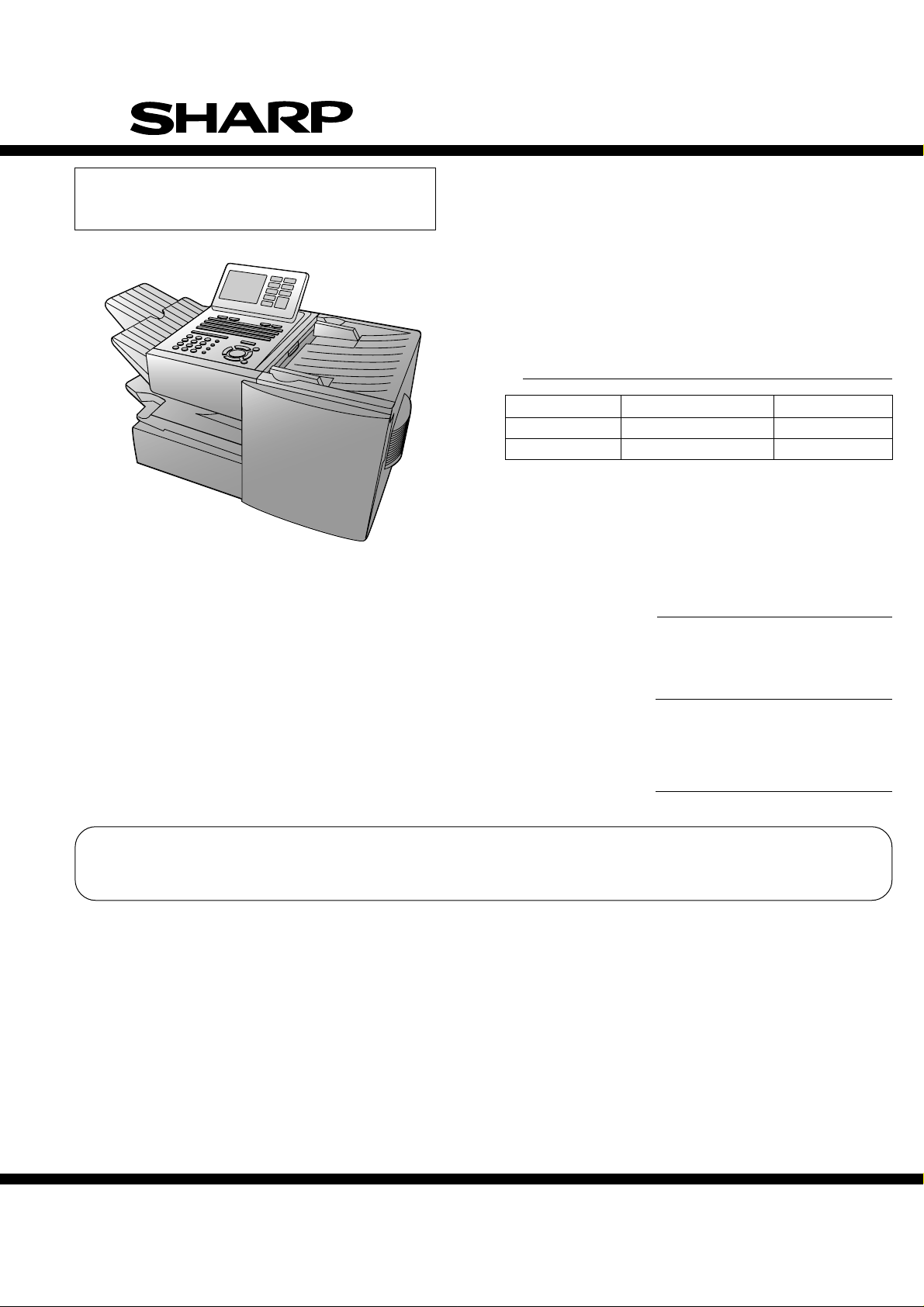
SERVICE MANUAL
SUPPLEMENT
FO-DC500U
FO-DC600U
No. 00ZFDC500SME2
FACSIMILE
FO-DC500
Illustration: FO-DC500
MODEL
MODEL SELECTION CODE DESTINATION
FO-DC500 U U.S.A./Canada
FO-DC600 U U.S.A./Canada
FO-DC600
OPTION
LAN Network interface kit
MODEL
Network printer kit
MODEL
Network scanner kit
MODEL
FO-LN1
FO-NP1
FO-NS2
The software for this model has been upgraded since September 2003. Refer to the additional
manual for changes in the software, specifications and parts.
This document has been published to be used
SHARP CORPORATION
for after sales service only.
The contents are subject to change without notice.
Page 2
FO-DC500U
FO-DC600U
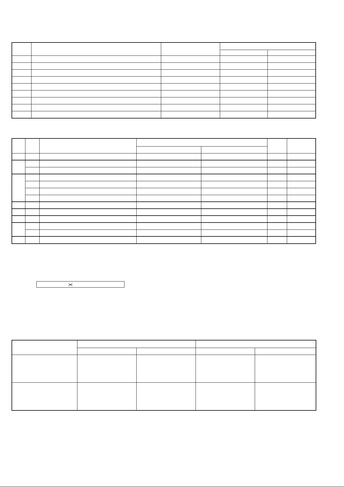
1. Specification changes
No. Description Purpose
1 REPORT key operations modified Functionality improvement 1-3 1-3
2 Max. scan length changed: 19 to 38 inches Functionality improvement 1-1, 1-4, 2-21 1-1, 2-21
3 Display thumbnails of attachments to Transaction Report Functionality improvement 2-21 2-21
4 Line monitor added Functionality improvement 2-14 2-14
5 Fax Transfer function added Functionality improvement 2-20 2-20
6 PC FAX function added Functionality improvement 2-20 2-20
7 Multicast transmission function added Functionality improvement 2-20 2-20
8 Insertion of separate page when network printing Functionality improvement 2-21, 2-23, 2-32, 2-33 2-21, 2-23, 2-32, 2-33
9 Activation switch added for activating new functions Service 2-2, 2-6 2-2, 2-6
Corresponding page in service manual
FO-DC500U FO-DC600U
2. Soft switch changes
SW
DATA
NO.
NO.
SW9 8 Action when RTN received Handle to no error Handle to error 0 Change
SW22
SW60
SW66
SW68
SW78
SW86
SW90
4 Line monitor up to Phase A On Off 0 Addition
5 Monitoring dial signal up to Phase A
1 Reserved 1 Change
2 Reserved 1 Change
3 Reserved 1 Change
4 Reserved 1 Change
7 Maximum size of input document 38 inch 19 inch 1 Addition
3 Image length of TX transaction report
4 Criterion of resolution when receiving Millimeter Not specified 0 Addition
6 Transferred fax image
7 Insertion of Adobe’s URL into E-mail No Yes 0 Addition
1 Method of detecting CI frequency Firmware Modem 0 Addition
ITEM
Monitoring fax signal and dial signal
Reduce image of whole 1st page 15 cm image from top of 1st page
Printed at transferred error only
Switch setting and function
10
Monitoring fax signal only 0 Addition
Printed every time 0 Addition
Initial
setting
Remarks
1 Addition
3. After upgrading FLASH ROM
After upgrading from version TA69D or earlier to TA69F (Sep. version) or later on FO-DC500, or after upgrading from version TA70C or earlier to TA70E
(Sep. version) or later on FO-DC600, perform the following to activate the functions 1, 2, 3, 5, 6 and 7 in “Specification changes”.
Go through MENU → 9 → → 8 → # → 7 → START to enter the diag mode. Then holding down Z key, select “Upgrade Setting” and press START
to perform upgrade.
* After this operation, the bit is set to “1” for soft switches SW60 No.1-No.4, SW66 No.7 and SW68 No.3.
* When there is no data to save, clear the memory after upgrading. Settings return to the default and the specification changes above become effective.
4. Connection between network option and FLASH ROM version
FO-LN1 FO-NP1
Manufactured in or before Aug. Manufactured in or after Sep. Manufactured in or before Aug. Manufactured in or after Sep.
FO-DC500: TA69D or earlier
FO-DC600: TA70C or earlier
FO-DC500: TA69F or later
FO-DC600: TA70E or later
(*1) : Existing functions are supported and none of new functions are.
(*2) : PC FAX cannot be used (additional software will be made available on the Web by U.S.A.)
(*3) : See the attached manual for the printer driver installation procedure.
O X(*1) O ∆(*3)
X(*2) O ∆(*3) O
– 1 –
Page 3
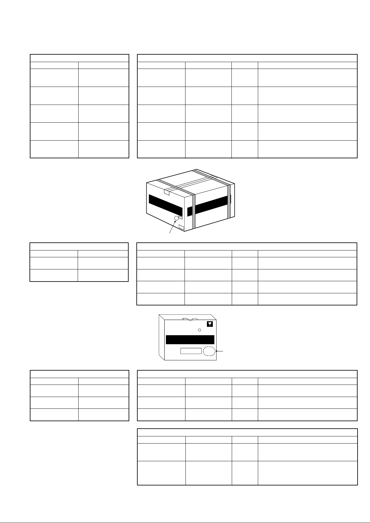
5. Part changes
FO-DC500/FO-DC600
CURRENT MODEL
Item Part code
FO-DC500
IC, FLASH ROM VHIF032/TA69D
(Ver.: TA69D)
FO-DC600
IC, FLASH ROM VHIF032/TA70C
(Ver.: TA70C)
FO-DC500
Operation panel case
GCASP2163XHSB
→
Item Part code Price rank Remarks
IC, FLASH ROM
(Ver.: TA69F)
IC, FLASH ROM
(Ver.: TA70E)
Operation panel case
From September Production
VHIF032/TA69F BP Upgrading FLASH ROM
VHIF032/TA70E BN Upgrading FLASH ROM
GCASP2163XHSK AZ
The change of the operation panel case
display.
FO-DC500U
FO-DC600U
FO-DC600
Operation panel case
Operation manual TINSE4302XHTC
GCASP2163XHSC
Operation panel case
GCASP2163XHSL AZ
Operation manual TINSE4302XHTD AS
* Look for stamp on the carton to distinguish before/after changed production.
SHARP
FO-DC500
FACSIMILE
FAC-SIMILE
SHARP CORPORATION
MADE IN TAILAND
C
Stamp of "C"
(Red color)
FO-LN1
CURRENT MODEL
Item Part code
→
Installation manual TCADZ3521XHZZ
CD ROM UDSKA2039XHZZ
* Look for stamp on the carton to distinguish before/after changed production.
Item Part code Price rank Remarks
Installation manual TCADZ3620XHZZ AG
CD ROM UDSKA2045XHZZ AY
PC FAX driver
installation manual installation.
Document admin
setting manual function.
TCADH3648XHZZ AE
TCADH3649XHZZ AE
SHARP
FO-DC500
FACSIMILE
FAC-SIMILE
From September Production
The change of the operation panel case
display.
Revise the operation manual by adding the
description of additional features.
Unification with FO-LN1G(For Europe and
Australia).
Add. PC FAX driver software and its
instruction data.
New instruction sheet for PC FAX driver
New instruction sheet for Document admin
FO-NP1
CURRENT MODEL
Item Part code
Installation manual TCADZ3523XHZZ
CD ROM UDSKA2040XHZA
Operation manual TINSE4313XHTZ
SHARP
R
FO-LN1
Stamp of "C"
c
(Red color)
From September Production
→
Item Part code Price rank Remarks
Installation manual TCADZ3621XHZZ AG
CD ROM UDSKA2040XHZB AY
Operation manual TINSE4313XHTB AM
↓
From November Production
Item Part code Price rank Remarks
CD ROM UDSKA2040XHZC
Operation manual TINSE4313XHTC AM
– 2 –
Unification with FO-NP1G(For Europe and
Australia).
Change of folder name of Printer Driver for
Windows 2000/XP.
Revise the operation manual changed by
the change above mentioned.
Multi-laguage Software and acquiring
AY WHQL and add. the operation manual
other than Englishversion into CD ROM.
Revise the operation manual by multi-
lingualization; Add. a note that other
language version is stored in CD ROM,
Multi-lingualization of software license.
Page 4

FO-DC500U
[
]
[Sp
]
FO-DC600U
FO-NS2
CURRENT MODEL
Item Part code
Operation manual TINSE4314XHTB
CD ROM UDSKA2041XHZA
From September Production
→
Item Part code Price rank Remarks
Operation manual TINSE4314XHTC AQ
Revise the operation manual by expansion
of Max. scanning length.
CD ROM UDSKA2041XHZA AY No change.
↓
From November Production
Item Part code Price rank Remarks
Add. a note that other languge versions is
Operation manual TINSE4314XHTD AQ stored in CD ROM, Multi-lingualization of
software license.
CD ROM UDSKA2041XHZB AY
Add. the operation manual other than
English version into CD ROM.
CHAPTER 1. GENERAL DESCRIPTION
[1] Specifications
• GENERAL
Input document size: Automatic feeding:
[3] Operation panel
11
01 02 03 04 05 06 07 08 09 10
Q / ! W / " E / # R / $ T / % Y / & U / ' I / ( O / ) P / =
11 12 13 14 15 16 17 18 19 20
SYMBOL
A / |S D F G / { H / } J / [ K / ] L / +
21 22 23 24 25 26 27 28 29 30
Caps Lock
Z / < X / > C V B N / * M / ? @ .com
31 32 33 34 35 36 37 38 39
/ ^ / / \ ; / :
SHIFT
11
40 41 42 43 44 45 46 47 48 49
Q / ! W / " E / # R / $ T / % Y / & U / ' I / ( O / ) P / =
50 51 52 53 54 55 56 57 58 59
SYMBOL
PAGE COUNTER
Caps Lock
SHIFT
14 15 16 17 18 19 2012 13
A / |S D F G / { H / } J / [ K / ] L / +
CONFIDENTIAL
TIMER
Z / < X / > C V B N / * M / ? @ .com
/ ^ / / \ ; / :
COVER SHEET
Width: 5.8 to 10.1” (148 to 256mm)
Length: 5.0 to 14.3” (128 to 364 mm)
Manual feeding:
Width: 5.8 to 11.0” (148 to 279 mm)
Length: 5.0 to 19.0” (128 to 483 mm)
LIFE
Space
MEM.STATUS
Space
_
REPORT
_
- . / , DEL
DOCUMENT
- . / , DEL
: Change
19
REPORT key
Press this key before sending a fax (or a Scan to E-mail/FTP/
Desktop transmission when the network scanner option is
installed) to have a transaction report printed out after the
transmission is finished.
[4] Transmittable documents
1. Document Sizes
Normal size
(Min.)
128 mm
148 mm 256 mm
width 5.8" – 10.1" (148 – 256 mm)
length 5.0" – 14.3" (128 – 364 mm)
(Max.)
364 mm
Normal size
(Max.)
966 mm
279 mm
ecial size
– 3 –
Page 5

: Change/Addition
HHHHHHHHHHHHHHHHHHHHHHHHHH
HHHHHHHHHHHHHHHHHHHHHHHHHH
HHHHHHHHHHHHHHHHHHHHHHHHHH
HHHHHHHHHHHHHHHHHHHHHHHHHH
HHHHHHHHHHHHHHHHHHHHHHHHHH
HHHHHHHHHHHHHHHHHHHHHHHHHH
HHHHHHHHHHHHHHHHHHHHHHHHHH
HHHHHHHHHHHHHHHHHHHHHHHHHH
HHHHHHHHHHHHHHHHHHHHHHHHHH
U:LCD CHECK MODE
1=CONT.ADJ 2=TEST DISP
CONTRAST=-9 TEMP=+25
A
[2] Diagnostics and service soft switches
1. Operating procedure
Two kinds of diagnoses are supported.
1-1. Fax diagnosis
This diagnosis is concerned with the main body of fax which is used for
production and service support.
Entering the diagnostic mode
MENU
Press
display will appear.
FAX
: TA69 or TA70
NIC :
x.xxx
PRN :
xxxx
PRN MEMORY SIZE
GAA
:
ESx GAB
Then press the
and the key or select with the rapid key.
Enter the mode with the
(Diag
•
specifications)
MENU
9 8
=
16(MB)
:
ESx
START
9 8 7
7
st
1
Line
nd
2
Line
rd
3
Line F/W version
th
4
Line NIC board version
th
5
Line PCL board version
th
6
Line
th
7
Line Memory size
th
8
Line GATE arrayA/B version
th
9
Line
, and
the
key. Select the desired item with the
START key.
TA69 or TA70
START
following
key
FO-DC500U
FO-DC600U
S) Dial test mode
The mode is used to inspect whether dialing is accurate in two kinds of
dial modes . All data which can be dialed in this mode are automatically
called up in both PB mode and DP mode.
[In case that 2 line optional is not mounted.]
1
Turn on CML, and dial the following in the PB mode.
1, 2, 3, 4, 5, 6, 7, 8, 9, , 0, #
2
Dial the following in the DP mode.
1, 5, 9, 0
3
After dialing, turn off CML.
NOTE:
This mode uses the ordinary auto dial. (Accordingly, the signal sending
time and minimum pause are all the same as ordinary.
The measurement result in this mode is completely all the same as in
the ordinary dial mode.)
T) Copy diag mode
This mode is for automatic mode selection of copy to reduce the time for
treatment at the time of production.
1
Set 2 sheets of document. (No problem if there are 2 sheets or
more.)
2
3 sheet continuous copy: 1st sheet in the FINE AUTO
NOTE: Input of the image quality and the darkness keys is invalid in this
mode.
U) LCD check mode
This is an item to check that the LCD acts normally.
1
The screen for selecting the contrast adjustment mode and the “H”
display mode appears.
2nd sheet and after that are copied in the
H-TONE DARK.
B PRINT AREA
C ROM & RAM CHECK
D AUTO FEEDER MODE
E AGING MODE
F PANEL CHECK MODE
G OPTICAL ADJUST MODE
H PRODUCT CHECK
I
J
K
L
M
N
O CONF. PASSCODE
P
Q
R
S
T
U
V
W
X
Y
Z
*: FONT LIST PRINT MODE can be used only when the
network function is effective.
STARTA SOFT SWITCH MODE
START
START
START
START
START
START
START
START
START
START
START
START
START
SIGNAL SEND MODE
COMM. CHECK MODE
MEMORY CLEAR MODE
FLASH MEMORY CHECK
ALL FAX/TEL. ENTRY MODE
DEPT. PASSCODE
START
START
START
START
START
START
START
START
START
START
START
START
SIGNAL SEND MODE 2
MEMORY SET MODE
STAMP AGING MODE
DIAL TEST MODE
COPY DIAG MODE
LCD CHECK MODE
PERSONAL BOOK LIST
FONT LIST PRINT MODE(*)
NO FUNCTION
NO FUNCTION
UPGRADE SETTING
2
Select the mode using the “←” or “→” keys or otherwise dial keys “1”
or “2”.
[When the contrast adjustment mode is selected]
3
Adjust with the “←” or “→” keys so that both right and left halves of
the “A” can be recognized.
[When the “H” display mode is selected]
3
Turn on the backlight so that the whole screen shows “H”.
(26 letters x 9 lines)
V) Personal book list
The PASSCODE of the personal book 00 to 10 are output.
W) Font list print mode
[Only when network function is mounted]
The font list that can be used in the network function is printed.
X) No function
Y) No function
Z) Upgrade setting
After upgrading from version TA69D or earlier to TA69F or later on
FO-DC500U, or after upgrading from version TA70C or earlier to TA70E
(Sep. version) or later on FO-DC600U, enter this mode to use new
functions.
– 4 –
Page 6

FO-DC500U
FO-DC600U
4. Soft switch description
• Soft switch
SW
DATA
NO.
NO.
CED tone signal interval 75ms 500ms 750ms 1000ms
1 No. 1 0 0 1 1 0
2 No. 2 0 1 0 1 0
3 Equalizer freeze On Off 0
4 Equalizer freeze conditions All 7200bps 0
SW9
5 CED detection time 500ms 1000ms 0
Alarm buzzer 3sec 1sec No BEEP No BEEP
6 No. 5 0 0 1 1 0
7 No. 6 0 1 0 1 0
8 Action when RTN received Handle to no error Handle to error 0
1 Reserved 0
2 Reserved 0
3 Reserved 0
SW22
SW60
SW66
SW68
SW78
SW86
SW90
4 Line monitor up to Phase A On Off 0
5 Monitoring dial signal up to Phase A
6 Reserved 0
7 Reserved 0
8 Reserved 0
1 Reserved 1
2 Reserved 1
3 Reserved 1
4 Reserved 1
5 Reserved 0
6 Reserved 0
7 Reserved 0
8 Reserved 0
1 Reserved 0
2 Reserved 0
3 Reserved 1
Cassette selection of separate page None Tray
4 No. 4 0 0 1 1 0
5 No. 5 0 1 0 1 1
6 Reserved 0
7 Maximum size of input document
8 Reserved 0
Distinctive ring pattern U.S.A. Canada Australia Hong Kong
1 No. 1 0 0 1 1 0 0
2 No. 2 0 1 0 1 0 1
3 Image length of TX transaction report
4 Reserved 1
5 Reserved 0
6 Reserved 0
7 Reserved 1
8 Reserved 0
1 Reserved 1
2 Reserved 0
3 Reserved 0
4 Criterion of resolution when receiving Millimeter Not specified 0
5 Reserved 0
6 Reserved 0
7 Reserved 0
8 Reserved 0
1 Reserved 0
2 Reserved 0
3 Reserved 0
4 Reserved 0
5 Reserved 0
6 Transferred fax image
7 Insertion Adobe’s URL into E-mail No Yes 0
8 Reserved 0
1 Method of detecting CI frequency Firmware Modem 0
2 Reserved 0
3 Reserved 1
4 Reserved 0
5 Reserved 0
6 Reserved 1
7 Reserved 0
8 Reserved 1
ITEM
: Change/Addition
Switch setting and function
1
Monitoring dial signal up to Phase A
STD/Fine/S-Fine=38 inch, U-Fine=19 inch
Reduced image of whole 1st page 15 cm image from top of 1st page
Printed at transferred error only
Monitoring fax signal only 0
19 inch 1
Printed every time 0
0
1st Cass. N/A
Initial
setting
For For
U.S.A. Canada
1
Remarks
OPTION
– 5 –
Page 7

: Change/Addition
• Soft switch function description
SW22 No. 1 ~ No. 3 Reserved
Set to "0".
SW22 No. 4 Line monitor up to Phase A
When set to “1”, the line sound is monitored until phase A.
SW22 No. 5 Monitoring dial signal up to Phase A
Dial signals as well as facsimile signals are set to be monitored by setting soft switch SW22 No.4 to “1” when it is active.
SW22 No. 6 ~ No. 8 Reserved
Set to "0".
SW60 No. 1 ~ No. 4 Reserved
Set to "1".
SW60 No. 5 ~ No. 8 Reserved
Set to "0".
SW66 No. 1, No. 2 Reserved
Set to "0".
SW66 No. 3 Reserved
Set to "1".
SW66 No. 4, No. 5 Cassette selection of separate page
The supply origin of a separate page is set.
SW66 No. 6 Reserved
Set to "0".
SW66 No. 7 Maximum size of input document
The maximum scan length can be switched.
SW66 No. 8 Reserved
Set to "0".
SW68 No. 1, No. 2 Distinctive ring pattern
The distinctive ring patter is set for country.
SW68 No. 3 Image length of TX transaction report
The size of images can be selected to attach to Transaction Report.
SW68 No. 4 Reserved
Set to "1".
FO-DC500U
FO-DC600U
SW68 No. 5, No. 6 Reserved
Set to "0".
SW68 No. 7 Reserved
Set to "1".
SW68 No. 8 Reserved
Set to "0".
SW78 No. 1 Reserved
Set to "1".
SW78 No. 2, No. 3 Reserved
Set to "0".
SW78 No. 4 Criterion of resolution when receiving
A standard resolution can be set for received images.
SW78 No. 5 ~ No. 8 Reserved
Set to "0".
SW86 No. 1 ~ No. 5 Reserved
Set to "0".
SW86 No. 6 Transferred fax image
By default, received fax images are printed by the machine. To set it to
print only when email forwarding fails, change this switch to “1”.
SW86 No. 7 Insertion of Adobe’s URL into E-mail
When sending emails with a PDF file attached, the URL of Adobe is
included in the body text. To prevent this, set this switch to “1”.
SW86 No. 8 Reserved
Set to "0".
SW90 No. 1 Method of detecting CI frequency
If CI signal detection is interrupted by noise, switch to Firmware detection.
SW90 No. 2 Reserved
Set to "0".
SW90 No. 3 Reserved
Set to "1".
SW90 No. 4, No. 5 Reserved
Set to "0".
SW90 No. 6 Reserved
Set to "1".
SW90 No. 7 Reserved
Set to "0".
SW90 No. 8 Reserved
Set to "1".
– 6 –
Page 8

FO-DC500U
FO-DC600U
COPYRIGHT © 2003 BY SHARP CORPORATION
ALL RIGHTS RESERVED.
No part of this publication may be reproduced,
stored in a retrieval system, or transmitted in
any form or by any means, electronic, mechanical,
photocopying, recording, or otherwise, without
prior written permission of the publisher.
SHARP CORPORATION
Communication Systems Group
Quality & Reliability Control Center
Higashihiroshima, Hiroshima 739-0192, Japan
Printed in U.S.A.
A0309-1100DS•IS•T
 Loading...