

Page 1
SERVICE MANUAL
No. 00ZFO4400USME
FACSIMILE
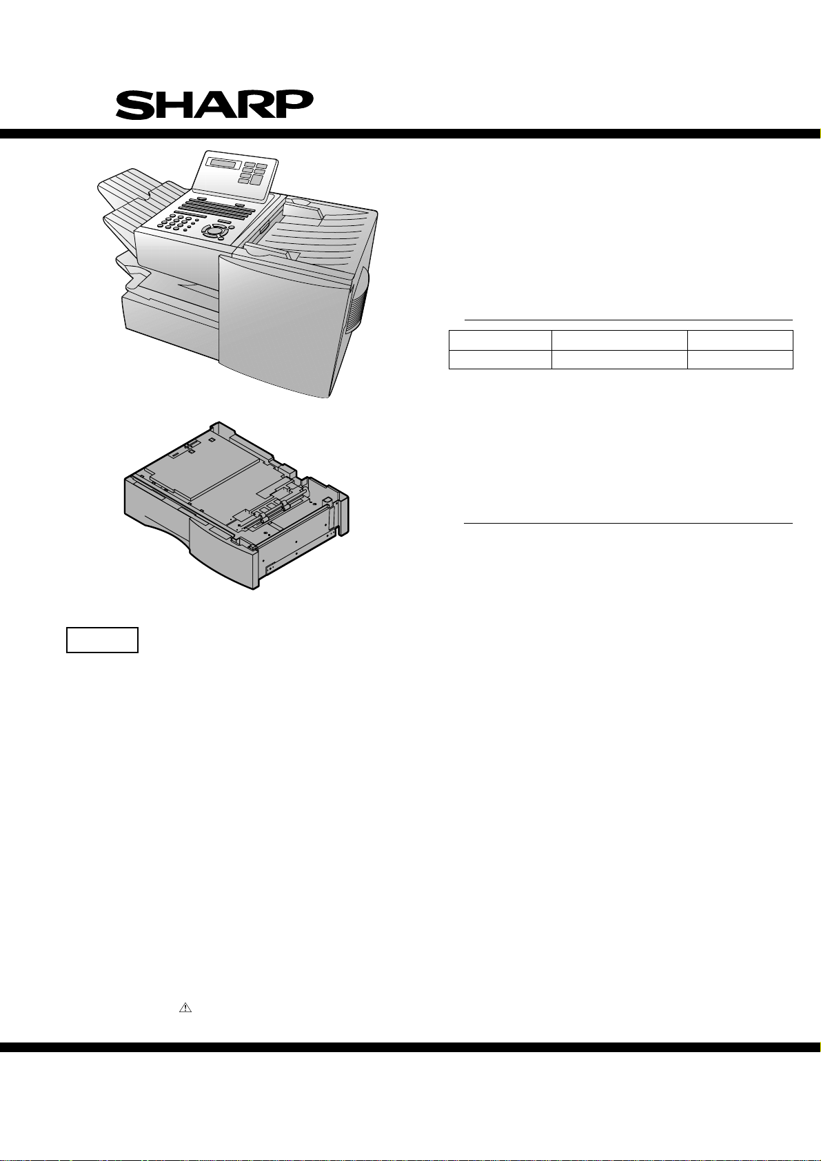
FO-4400U
FO-CS1
MODEL
MODEL SELECTION CODE DESTINATION
FO-4400 U U.S.A./Canada
Illustration: FO-4400
FO-4400
OPTION:PAPER CASSETTE
MODEL
Illustration: FO-CS1
CAUTION
This laser printer is a class 1 laser product that complies with 21CFR 1040.10 and 1040.11 of the CDRH or IEC60825-1 standard. This
means that this machine does not produce a hazardous laser radiation. The use of controls, adjustments or performance of procedures
other than those specified herein may result in hazardous radiation exposure.
This laser radiation is not a danger to the skin, but when an exact focusing of the laser beam is achieved on the eyes retina, there is
danger of spot damage to the retina.
The following cautions must be observed to avoid exposure of the laser beam to your eyes at the time of servicing.
1) When a problem in the laser optical unit has occurred, the whole optical unit must be exchanged as a unit, not an individual part.
2) Do not look into the machine with the main switch turned on after removing the toner/developer unit and drum cartridge.
3) Do not look into the laser beam exposure slit of the laser optical unit with the connector connected when removing and installing the
optical system.
4) The cover of Laser Printer Unit contains the safety interlock switch.
Do not defeat the safety interlock by inserting wedges or other items into the switch slot.
FO-CS1
OPTION
Toner cartridge: FO-50ND
Drum cartridge: FO-47DR
Option memory: FO-8MK
Verification stamp: FO-45VS
Paper cassette: FO-CS1
Laser Wave Length : 770-795 nm
Laser Pulse Times
Laser Output Power : 5 mW
Parts marked with " " is important for maintaining the safety of the set. Be sure to replace these parts with specified ones for
maintaining the safety and performance of the set.
: 51.3 ns
SHARP CORPORATION
1 - 1
This document has been published to be used
for after sales service only.
The contents are subject to change without notice.
Page 2

FO-4400U
FO-CS1
• CAUTION FOR BATTERY REPLACEMENT
• PRECAUTIONS FOR USING LEAD-FREE SOLDER
CHAPTER 1. GENERAL DESCRIPTION
[1] Specifications . . . . . . . . . . . . . . . . . . . . . . . . . . . . . . . . . . . . . . . . . . . . . . . . . . . . . . . . . . . . . . . . . . 1-1
[2] Life of consumable . . . . . . . . . . . . . . . . . . . . . . . . . . . . . . . . . . . . . . . . . . . . . . . . . . . . . . . . . . . . . . 1-1
[3] Operation panel . . . . . . . . . . . . . . . . . . . . . . . . . . . . . . . . . . . . . . . . . . . . . . . . . . . . . . . . . . . . . . . . 1-2
[4] Transmittable documents . . . . . . . . . . . . . . . . . . . . . . . . . . . . . . . . . . . . . . . . . . . . . . . . . . . . . . . . . 1-3
[5] Installation . . . . . . . . . . . . . . . . . . . . . . . . . . . . . . . . . . . . . . . . . . . . . . . . . . . . . . . . . . . . . . . . . . . . 1-4
[6] Quick reference guide . . . . . . . . . . . . . . . . . . . . . . . . . . . . . . . . . . . . . . . . . . . . . . . . . . . . . . . . . . 1-11
CHAPTER 2. ADJUSTMENTS
[1] Adjustments . . . . . . . . . . . . . . . . . . . . . . . . . . . . . . . . . . . . . . . . . . . . . . . . . . . . . . . . . . . . . . . . . . . 2-1
[2] Diagnostics and service soft switches . . . . . . . . . . . . . . . . . . . . . . . . . . . . . . . . . . . . . . . . . . . . . . . 2-2
[3] Troubleshooting . . . . . . . . . . . . . . . . . . . . . . . . . . . . . . . . . . . . . . . . . . . . . . . . . . . . . . . . . . . . . . . 2-35
[4] Error code table . . . . . . . . . . . . . . . . . . . . . . . . . . . . . . . . . . . . . . . . . . . . . . . . . . . . . . . . . . . . . . . 2-36
[5] Overseas communication mode . . . . . . . . . . . . . . . . . . . . . . . . . . . . . . . . . . . . . . . . . . . . . . . . . . . 2-38
[6] Administrator mode in the personal book function . . . . . . . . . . . . . . . . . . . . . . . . . . . . . . . . . . . . . 2-38
CHAPTER 3. MECHANICAL DESCRIPTION
[1] Mechanical description . . . . . . . . . . . . . . . . . . . . . . . . . . . . . . . . . . . . . . . . . . . . . . . . . . . . . . . . . . . 3-1
[2] Printer description . . . . . . . . . . . . . . . . . . . . . . . . . . . . . . . . . . . . . . . . . . . . . . . . . . . . . . . . . . . . . . 3-2
[3] Disassembly and assembly procedures . . . . . . . . . . . . . . . . . . . . . . . . . . . . . . . . . . . . . . . . . . . . . . 3-9
[4] How to install the verification stamp (FO-45VS) . . . . . . . . . . . . . . . . . . . . . . . . . . . . . . . . . . . . . . 3-33
CONTENTS
CHAPTER 4. DIAGRAMS
[1] Block diagram . . . . . . . . . . . . . . . . . . . . . . . . . . . . . . . . . . . . . . . . . . . . . . . . . . . . . . . . . . . . . . . . . 4-1
[2] Wiring diagram . . . . . . . . . . . . . . . . . . . . . . . . . . . . . . . . . . . . . . . . . . . . . . . . . . . . . . . . . . . . . . . . . 4-2
[3] Point-to-point diagram and connector signal name . . . . . . . . . . . . . . . . . . . . . . . . . . . . . . . . . . . . . 4-3
CHAPTER 5. CIRCUIT DESCRIPTION
[1] Circuit description . . . . . . . . . . . . . . . . . . . . . . . . . . . . . . . . . . . . . . . . . . . . . . . . . . . . . . . . . . . . . . . 5-1
[2] Circuit description of control PWB . . . . . . . . . . . . . . . . . . . . . . . . . . . . . . . . . . . . . . . . . . . . . . . . . . 5-1
[3] Circuit description of CIS unit . . . . . . . . . . . . . . . . . . . . . . . . . . . . . . . . . . . . . . . . . . . . . . . . . . . . . 5-15
[4] Circuit description of LIU PWB . . . . . . . . . . . . . . . . . . . . . . . . . . . . . . . . . . . . . . . . . . . . . . . . . . . . 5-16
[5] Circuit description of operation panel PWB . . . . . . . . . . . . . . . . . . . . . . . . . . . . . . . . . . . . . . . . . . 5-18
[6] Circuit description of power supply PWB . . . . . . . . . . . . . . . . . . . . . . . . . . . . . . . . . . . . . . . . . . . . 5-19
CHAPTER 6. CIRCUIT SCHEMATICS AND PARTS LAYOUT
[1] Control PWB circuit . . . . . . . . . . . . . . . . . . . . . . . . . . . . . . . . . . . . . . . . . . . . . . . . . . . . . . . . . . . . . 6-1
[2] LIU PWB circuit . . . . . . . . . . . . . . . . . . . . . . . . . . . . . . . . . . . . . . . . . . . . . . . . . . . . . . . . . . . . . . . 6-18
[3] Printer PWB circuit . . . . . . . . . . . . . . . . . . . . . . . . . . . . . . . . . . . . . . . . . . . . . . . . . . . . . . . . . . . . . 6-21
[4] Power supply PWB circuit . . . . . . . . . . . . . . . . . . . . . . . . . . . . . . . . . . . . . . . . . . . . . . . . . . . . . . . 6-25
[5] Operation panel PWB circuit . . . . . . . . . . . . . . . . . . . . . . . . . . . . . . . . . . . . . . . . . . . . . . . . . . . . . 6-27
[6] 2nd paper cassette PWB circuit (FO-CS1) . . . . . . . . . . . . . . . . . . . . . . . . . . . . . . . . . . . . . . . . . . 6-31
CHAPTER 7. OPERATION FLOWCHART
[1] G3 protocol . . . . . . . . . . . . . . . . . . . . . . . . . . . . . . . . . . . . . . . . . . . . . . . . . . . . . . . . . . . . . . . . . . . . 7-1
[2] Super G3 protocol . . . . . . . . . . . . . . . . . . . . . . . . . . . . . . . . . . . . . . . . . . . . . . . . . . . . . . . . . . . . . . 7-2
[3] Power on sequence . . . . . . . . . . . . . . . . . . . . . . . . . . . . . . . . . . . . . . . . . . . . . . . . . . . . . . . . . . . . . 7-3
CHAPTER 8. OTHERS
[1] Service Tools . . . . . . . . . . . . . . . . . . . . . . . . . . . . . . . . . . . . . . . . . . . . . . . . . . . . . . . . . . . . . . . . . . 8-1
[2] Rewriting version up the FLASH ROM . . . . . . . . . . . . . . . . . . . . . . . . . . . . . . . . . . . . . . . . . . . . . . . 8-2
P ARTS GUIDE
1 – 2
Page 3
CAUTION FOR BATTERY REPLACEMENT
(Danish) ADVARSEL !
Lithiumbatteri-Eksplosionsfare ved fejlagtig håndtering.
Udskiftning må kun ske med batteri af samme fabrikat og type.
Levér det brugte batteri tilbage til leverandoren.
(English) Caution !
Danger of explosion if battery is incorrectly replaced.
Replace only with the same or equivalent type
recommended by the equipment manufacturer.
Discard used batteries according to manufacturer’s instructions.
(Finnish) VAROITUS
Paristo voi räjähtää, jos se on virheellisesti asennettu.
Vaihda paristo ainoastaan laitevalmistajan suosittelemaan
tyyppiin. Hävitä käytetty paristo valmistajan ohjeiden mukaisesti.
PRECAUTIONS FOR USING LEAD-FREE SOLDER
FO-4400U
FO-CS1
(French) ATTENTION
Il y a danger d’explosion s’ il y a remplacement incorrect
de la batterie. Remplacer uniquement avec une batterie du
même type ou d’un type recommandé par le constructeur.
Mettre au rébut les batteries usagées conformément aux
instructions du fabricant.
(Swedish) VARNING
Explosionsfare vid felaktigt batteribyte.
Använd samma batterityp eller en ekvivalent
typ som rekommenderas av apparattillverkaren.
Kassera använt batteri enligt fabrikantens
instruktion.
(German) Achtung
Explosionsgefahr bei Verwendung inkorrekter Batterien.
Als Ersatzbatterien dürfen nur Batterien vom gleichen Typ oder
vom Hersteller empfohlene Batterien verwendet werden.
Entsorgung der gebrauchten Batterien nur nach den vom
Hersteller angegebenen Anweisungen.
11
1
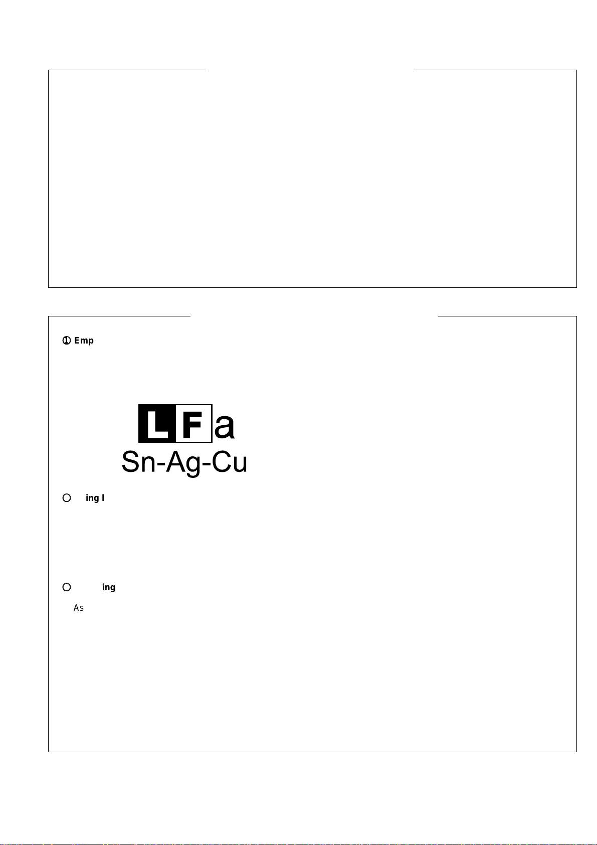
Employing lead-free solder
11
The Power supply PWB of this model employs lead-free solder. This is indicated by the “LF” symbol printed on the PWB
and in the service manual.
The suffix letter indicates the alloy type of the solder.
Example:
Indicates lead-free solder of tin, silver and copper.
22
2
Using lead-free solder
22
When repairing a PWB with the “LF” symbol, only lead-free solder should be used. (Using normal tin/lead alloy solder may
result in cold soldered joints and damage to printed patterns.)
As the melting point of lead-free solder is approximately 40ºC higher than tin/lead alloy solder, it is recommended that a
dedicated bit is used, and that the iron temperature is adjusted accordingly.
33
3
Soldering
33
As the melting point of lead-free solder (Sn-Ag-Cu) is higher and has poorer wettability (flow), to prevent damage to the land
of the PWB, extreme care should be taken not to leave the bit in contact with the PWB for an extended period of time.
Remove the bit as soon as a good flow is achieved.
The high content of tin in lead free solder will cause premature corrosion of the bit.
To reduce wear on the bit, reduce the temperature or turn off the iron when it is not required.
Leaving different types of solder on the bit will cause contamination of the different alloys, which will alter their
characteristics, making good soldering more difficult.
It will be necessary to clean and replace bits more often when using lead-free solder. To reduce bit wear, care should be
taken to clean the bit thoroughly after each use.
1 - 3
Page 4

FO-4400U
FO-CS1
CHAPTER 1. GENERAL DESCRIPTION
[1] Specifications
• GENERAL
Automatic dialing: Conventional Auto Dialing:
Rapid Key Dialing: 59 numbers
Speed Dialing: 75 numbers
Personal Auto Dial Books: 10 books
(59 Rapid Keys, 16 Speed Dial
numbers per book)
Memory size* : 2 MB (approx. 124 pages)
Optional memory: FO-8MK (8 MB;
approx. 500 pages)
Modem speed: 33,600 bps (max.) with automatic
fallback to lower speeds
Transmission time* : Approx. 3 seconds
Toner cartridge yield: Initial starter cartridge (included with
(continuous printing, fax machine): Approx. 3000 pages
4% page coverage, Replacement cartridge (FO-50ND):
letter paper) Approx. 6000 pages
Drum cartridge yield: Initial starter cartridge (included with
fax machine): 20,000 pages (avg.)
Replacement cartridge (FO-47DR):
20,000 pages (avg.)
Resolution: Horizontal:
203 pixels/inch (8 dots/mm)
Vertical:
Standard: 98 lines/inch (3.85 lines/mm)
Fine/Halftone: 196 lines/inch
(7.7 lines/mm)
Super fine: 391 lines/inch (15.4 lines/mm)
Automatic document feeder: Letter paper (20 lb): Max. 50 pages
Legal paper: Max. 20 pages
(Note: 11” x 17” paper must be loaded
one page at a time.)
Paper capacity: 250 sheets (20 lb)
(500-sheet cassette available as option)
Compression scheme: MMR, MR, MH, Sharp (H2)
Halftone (grayscale): 64 levels
Applicable telephone line: Public switched telephone network
Compatibility: ITU-T (CCITT) G3 mode, Super G3
mode
Printing resolution: Horizontal: 406 lines/inch (16 lines/mm)
Vertical: 391 lines/inch (15.4 lines/mm)
Input document size: Automatic feeding:
Width: 5.8 to 10.1” (148 to 256mm)
Length: 5.0 to 14.3” (128 to 364 mm)
Manual feeding:
Width: 5.8 to 11.0” (148 to 279 mm)
Length: 5.0 to 19.0” (128 to 483 mm)
Effective scanning width: 8.2” (208 mm) max.
Effective printing width: 8.0” (203 mm) max.
Reception modes: Auto/Manual
Instascan speed: 1.3 sec/page (letter paper; scan time
only, excludes document feeding time)
Full Dual Access: Yes
Copy function: Single/Multi/Sort (99 copies/page)
Power requirements: 120 V AC, 60 Hz
Operating temperature: 50 - 86°F(10 - 30°C)
Humidity: 20 to 85 % RH
Power consumption: Stand-by: 9 W
Maximum: 760 W
Dimensions: Width: 21.5” (546 mm)
Depth: 16.2” (412 mm)
Height: 13.6” (346 mm)
(Not including paper tray or attachments)
Weight: Approx. 31.3 lbs. (14.2 kg)
(Not including supplies paper tray or
attachments)
* Based on ITU-T Test Chart #1 at standard resolution, excluding time for
protocol signals (i.e., ITU-T phase C time only).
<IMPORTANT PLEASE READ FIRST>
To avoid problems with supplies, please don’t use supplies from other units. Please use new supplies, when supply changes are required.
[2] Life of consumable
Section Part Estimated Life Replaced by
Toner cartridge Replacement cartridge 6,000 prints User
(FO-50ND) (at Letter/4% chart)
Drum cartridge Replacement cartridge 20,000 prints User
(FO-47DR) (at Letter/4% chart)
Paper feed Transfer roller
(0KW4127410302)
Fuser Fusing unit
(0KW4127035501)
Paper transport
Paper transfer roller (Refer to the P/G No. 8-6)
(0KW4127300101)
Unit FO-4400 5 years or 75,000 prints ———————
(Refer to the P/G No. 10-8)
(Refer to the P/G No. 9-14)
1 – 1
50,000 prints Service Engineer
50,000 prints Service Engineer
Cleaning as needed ———————
of early either
Page 5
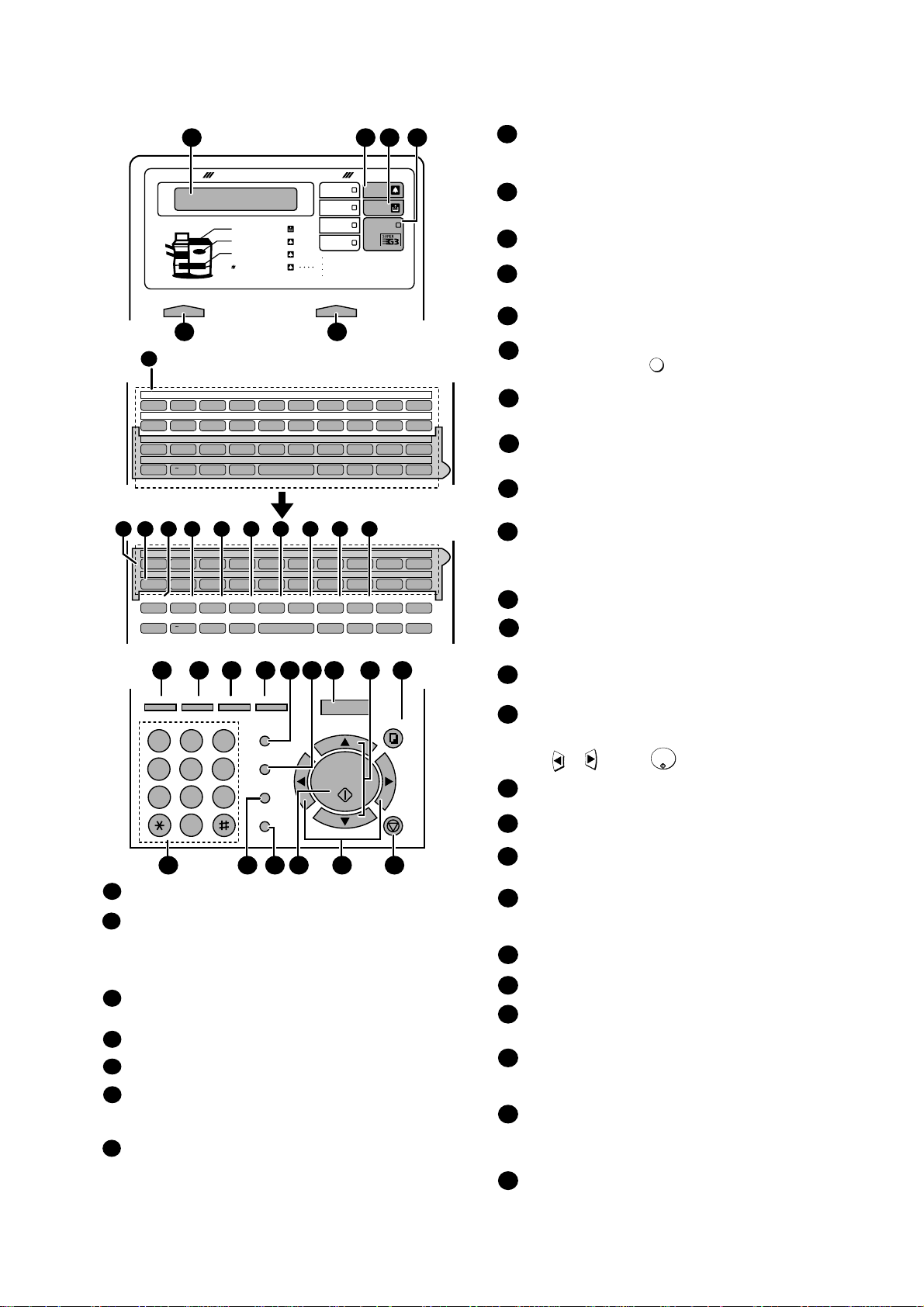
[3] Operation panel
Q / ! W / " E / # R / $ T / % Y / & U / ' I / ( O / ) P / =
SYMBOL
A / |S D F G / { H / } J / [ K / ] L / +
Caps Lock
Z / < X / > C V B N / * M / ? @ .com
SHIFT
/ ^
/ / \ ; / :
Space
_
- . / , DEL
Q / ! W / " E / # R / $ T / % Y / & U / ' I / ( O / ) P / =
SYMBOL
A / |S D F G / { H / } J / [ K / ] L / +
Caps Lock
PAGE COUNTER
CONFIDENTIAL
TIMER
COVER SHEET
LIFE
MEM.STATUS
REPORT
DOCUMENT
Z / < X / > C V B N / * M / ? @ .com
SHIFT
/ ^
/ / \ ; / :
Space
_
- . / , DEL
01 02 03 04 05 06 07 08 09 10
11 12 13 14 15 16 17 18 19 20
40 41 42 43 44 45 46 47 48 49
50 51 52 53 54 55 56 57 58 59
21 22 23 24 25 26 27 28 29 30
31 32 33 34 35 36 37 38 39
7
7
8 10 11 12 13 14 15 16
PLAIN PAPER LASER FACSIMILE
HALF TONE
Toner Cartridge
Drum Cartridge
Paper Supply
Paper Jam
Paper Size Error
Printer Cover Open
Out Put Tray Error
ALARM Guide
ALARM
TONER
LINE IN USE
CONTRAST RESOLUTION
STANDARD
FINE
SUPER FINE
1
5
2 3 4
6
JKL
ABC1DEF
WXYZ
9
GHI
4
5
MNO
6
PQRS
7
TUV
8
0
2 3
OPER
PERSONAL
BOOK
SPEED DIAL
REDIAL
SPEAKER
JOB STATUS
DUPLEX SCAN
PRIORITY
BROADCAST
MENU
UP
ZA
DOWN
START/
ENTER
COPY/HELP
STOP
1717 24241818 1919 2020 2525
2626 3030 31312727 2929
2323
2828
22222121
PAGE COUNTER key
Press this key to include a slash and the total number of pages after each
page number on the pages of a transmitted document.
CONFIDENTIAL key
Press this key to send or print out a confidential document.
TIMER key
Press this key to set an operation to be performed automatically at a later
time.
11
COVER SHEET key
Press this key to include a cover sheet when sending a fax.
LIFE key
Press this key, followed b y , to check the total number o f pag es printed
by the fax machine.
MEM. ST ATUS key
Press this key to chec k the status of fax transmission jobs, copy jobs, and
receptions.
fax This key can also be used to cancel a job.
REPORT key
Press this key to print out a report on the most recently completed
transmission or reception.
DOCUMENT key
Press this key to trans mit a docu ment dire ctly from t he f e eder without
it into memory .
1
15
16
13
12
14
JOB STATUS key
Two types of information appear in the display: prompts related to
operations
you are performing, and information about how the fax machine
is
using the telephone line (transmitting, receiving, etc.). Press this key to
between the two types of information.
DUPLEX SCAN key
Press this key to transmit or copy a two-sided document.
PRIORITY key
Press this key when you need to transmit a document ahead of other
documents waiting in memory for transmission.
BROADCAST key
Press this key to send a fax to a group of receiving fax machines.
17
19
20
18
PERSONAL BOOK
Press this key to use or store an auto-dial number in a personal book. If
book has a passcode, enter the passcode; otherwise, select the book
with
or and press .
SPEED DIAL key
Press this key to dial a Speed Dial number.
MENU key
Press this key to select special functions and settings.
UP and DOWN arrow keys
Volume setting: Press these keys to change the speaker volume when the
SPEAKER key has been pressed, or the ringer volume at any other time.
COPY/HELP key
When a document is in the feeder, press this key to make a copy of a
document. At any other time, press this key to print out the Help List, a
reference guide to the operation of your fax machine.
Dial keypad (numeric keys)
Use these keys to dial and program fax numbers.
REDIAL key
Press this key to automatically redial the last number dialed.
SPEAKER key
Press this key wh en trans mittin g a document b y Normal Dialing to l isten to
the
line and verify the response of the receiving fax machine.
START/ENTER key
Press this key to begin fax transmission when using Speed Dialing, Direct
Keypad Dialing, or Normal Dialing. This key i s also use d to sel ect s etting s
and
complete entries when storing names and numbers.
Left and right arrow keys
Auto-dial numbers: Press these keys to search for an auto-dial number
when sending a fax.
MENU key settings: Press these keys after pressing the MENU key to
scroll
through the MENU key settings.
STOP key
Press this key to cancel an operation before it is completed.
START/
ENTER
24
25
26
27
28
29
30
31
23
21
22
Display
This displays messages and prompts to help you operate the machine.
ALARM indicator
This blinks when one of the paper sources is empty or the drum cartridge is
near the end of its life (printing is still possible). This lights steadily when the
drum cartridge has reached the end of its lif e, all paper sources are empty, the
print compartment cover is open, or a paper jam has occurred (printing is not
possible). A message will appear in the display to indicate the problem.
TONER indicator
This blinks when the toner cartridge nears empt y, and lights steadily when
the
toner cartridge needs replacement.
LINE IN USE light
This lights when the fax machine is using the telephone line.
CONTRAST key
Press this key to adjust the contrast before sending or copying a document.
RESOLUTION key
Press this key to adj us t the res ol uti on be fore sending or copying a document.
An indicator will light next to the selected setting (HALFTONE, STANDARD,
FINE or SUPER FINE).
1
2
3
4
5
6
reading
change
the
quick
9
Rapid Dial Keys
Press one of these keys to dial a fax number automatically. (Note that you
must attach the Rapid Key labels.) When navigating through the display
menu, a Rapid Key can also be pressed in place of the numeric keys to
enter a two-digit number (for example, you can press Rapid Key 01 to enter
the number “01”).
7
10
9
SYMBOL key
When entering a name, press this key to enter the symbol on a letter key
(the character to the right of the slash). Press the key again to turn off
symbol entry mode.
8
1 – 2
FO-4400U
FO-CS1
Page 6
FO-4400U
(
)
[
]
[Sp
]
FO-CS1
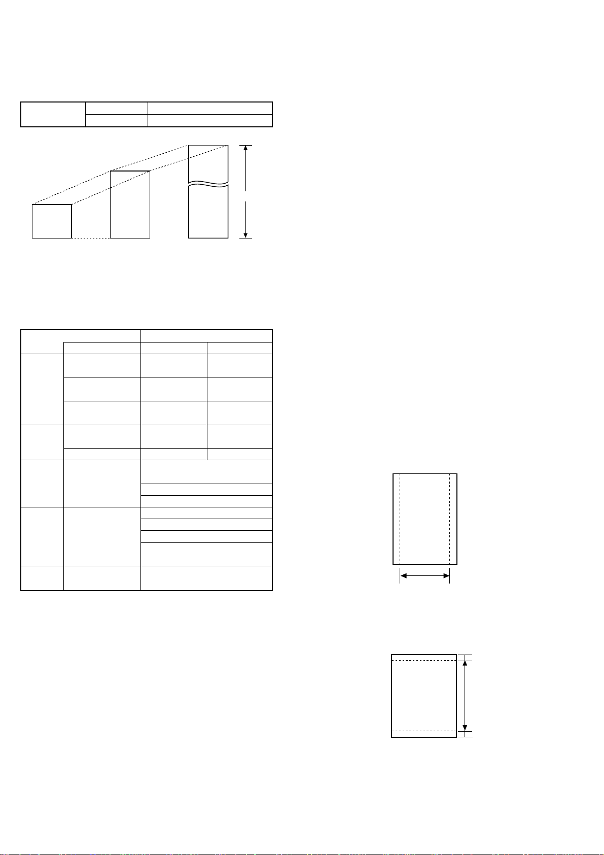
[4] Transmittable documents
1. Document Sizes
Normal size
(Min.)
128 mm
148 mm 256 mm
* With special sizes, only one sheet can be fed into the machine at a
time. Insert next page into feeder as current page is being scanned.
2. Paper Thickness & Weight
Weight Japanese indication 45kg paper 70kg paper
indication Size 4 × 6
Metric system 52g/m
indication
American indication 14 LB 20 LB
LB system indication
Thickness Metric system 0.06mm 0.1mm
indication indication
Inch system indication 0.0024
Document Document size (148mm × 128mm) ~
size Range W letter (279mm × 483mm)
Number of Document size B6 ~ Letter/A4 size 50 sheets
ADF sheets
Paper Kind Paper of fine quality/bond paper/
quality Kent paper
Weight B4 size/Legal 20 sheets
3. Document Types
• Normal paper
Documents handwritten in pencil (No. 2 lead or softer), fountain pen,
ball point pen, or felt-tipped pen can be transmitted.
Documents of normal contrast duplicated by a copying machine can
also be transmitted.
• Diazo copy (blueprint)
Diazo copy documents of a normal contrast may be transmitted.
• Carbon copy
A carbon copy may be transmitted if its contrast is normal.
width 5.8" – 10.1" (148 – 256 mm)
length 5.0" – 14.3" (128 – 364 mm)
(Max.)
80g/m
0.0035
483 mm
2
"
(Max.)
Normal size
Indication Lower Limit Upper Limit
364 mm
279 mm
ecial size
Product specifications
2
"
A4 (210mm × 297mm)
Letter (216mm × 279mm)
W letter size 1 sheet
90 kg (104g/m2) or more
135 kg (157g/m2) or less1 sheet
4. Cautions on Transmitting Documents
• Documents written in yellow, greenish yellow, or light blue ink cannot
be transmitted.
• Ink, glue, and correcting fluid on documents must be dry before the
documents can be transmitted.
• All clips, staples and pins must be removed from documents before
transmission.
• Patched (taped) documents should be copied first on a copier and
then the copies used for transmission.
• All documents should be fanned before insertion into the feeder to
prevent possible double feeds.
5. Automatic Document Feeder Capacity
Number of pages that can be placed into the feeder at anytime is as
follows:
Normal size: max. 50 sheets (14 lbs - 20 lbs)
Special size: single sheet only (manual feed)
NOTES: • If you need to send or copy more 50 pages, place the ad-
ditional pages and carefully in the feeder just before the
last page is scanned. Do not try to force them in, as this
may cause double-feeding or jamming.
• If your document consists of several large or thick pages
which must be loaded one at a time, insert each page into
the feeder as the previous page is being scanned. Insert
gently to prevent doublefeeding.
6. Readable Width & Length
The readable width and length of a document are slightly smaller than
the actual document size.
Note that characters or graphics outside the effective document scanning range will not be read.
• Readable width
8.2" (208 mm) max.
Readable width
• Readable length
This is the length of the document sent minus 0.16" (4 mm) from the top
and bottom edges.
0.16"(4mm)
Readable length
4mm
0.16"
1 – 3
Page 7
[5] Installation
1. Site selection
T ake the following points into consideration when selecting a site for this
model.
ENVIRONMENT
• The machine must be installed on a level surface.
• Keep the machine away from air conditioners, heaters, direct sun-
light, and dust.
• Provide easy access to the front, back, and sides of the machine. In
particular, keep the area in front of the machine clear, or the original
document may jam as it comes out after scanning.
• The temperature should be between 50° and 86°F (10° and 30°C).
• The humidity should be between 30% and 85% (without condensa-
tion).
ELECTRICITY
AC 120 V, 60 Hz, grounded (3-prong) AC outlet is required.
Caution!
• Connection to a power source other than that specified will cause
damage to the equipment and is not covered under the warranty.
• If your area experiences a high incidence of lightning or power surges,
we recommend that you install a surge protector for the power and
telephone lines. Surge protectors can be purchased at most telephone
specialty stores.
TELEPHONE JACK
A standard RC11C telephone jack must be located near the machine.
This is the telephone jack commonly used in most homes and offices.
• Plugging the fax machine into a jack which is not an RC11C jack may
result in damage to the machine or your telephone system. If you do
not know what kind of jack you have, or need to have one installed,
contact the telephone company.
If the machine is moved from a cold to a warm place...
If the machine is moved from a cold to a warm place, it is possible that
the reading glass may fog up, preventing proper scanning of documents
for transmission. T o remove the fog, turn on the power and wait approximately 2 hours before using the machine.
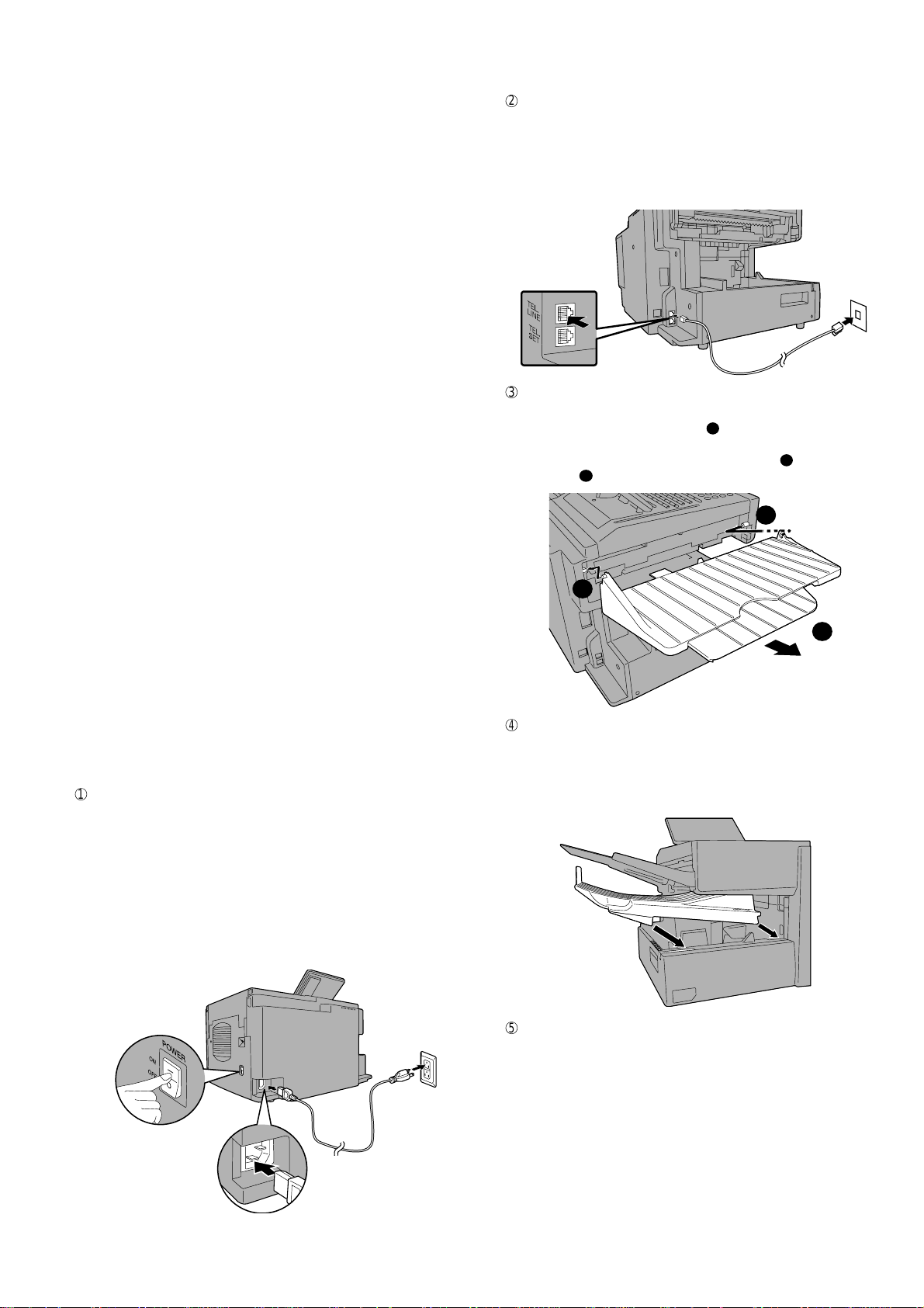
2. Assembly and connections
1
Connecting the power cord
Connect the female end of the power cord to the fax machine as
shown. Insert the male end into a 120 V, 60 Hz, grounded (3-prong)
AC outlet.
Important!: The fax machine requires its own dedicated power outlet.
The power outlet must not be shared with any other devices. In particular, do not use an extension cord to connect multiple devices to the
outlet.
Note: If your area experiences a high incidence of lightning or power
surges, we recommend that you install surge protectors for the power
and telephone lines. Surge protectors can be purchased at most telephone specialty stores.
FO-4400U
FO-CS1
2
Connecting the telephone line cord
Insert one end of the line cord into the jack on the back of the machine marked TEL. LINE. Insert the other end into a standard (RJ1 1C)
single-line wall telephone jack.
Note: The fax machine is set for touch-tone dialing. If you are on a pulse
dial (rotary) line, you must set the fax machine for pulse dialing by changing Option Setting 22.
3
Attaching the ADF exit tray
Insert the protrusion on the right side of the machine into the hole in
the right side of the ADF exit tray 1, then bend the tray slightly and
insert so that the protrusion on the left side of the machine goes into
the hole on the left side of the ADF exit tray 2. Pull out the tray
extension 3.
1
2
3
4
Attaching the received document tray
Slide the received document tray into the machine as shown. When
it stops, lift the end slightly and push in so that the tray locks into
place.
Important!: The received document tray must be attached for the fax
machine to operate properly.
Press the power
switch to turn on
the power.
1 – 4
5
Verification Stamp option (FO-45VS)
Note: This feature is available as an option. Consult your dealer if
you wish to use this feature.
When transmitting a document, you can have the fax machine stamp
each document page as it is scanned. After scanning, you can check
to see if all document have been stamped to verify that no double
feeds occurred. (A double feed occurs when two pages are fed through
the scanner at once, which means that one of the pages is not
scanned.)
To use this function, have your dealer install the Verification Stamp
option, and then set Option Setting 29 to ON.
Page 8
FO-4400U
FO-CS1
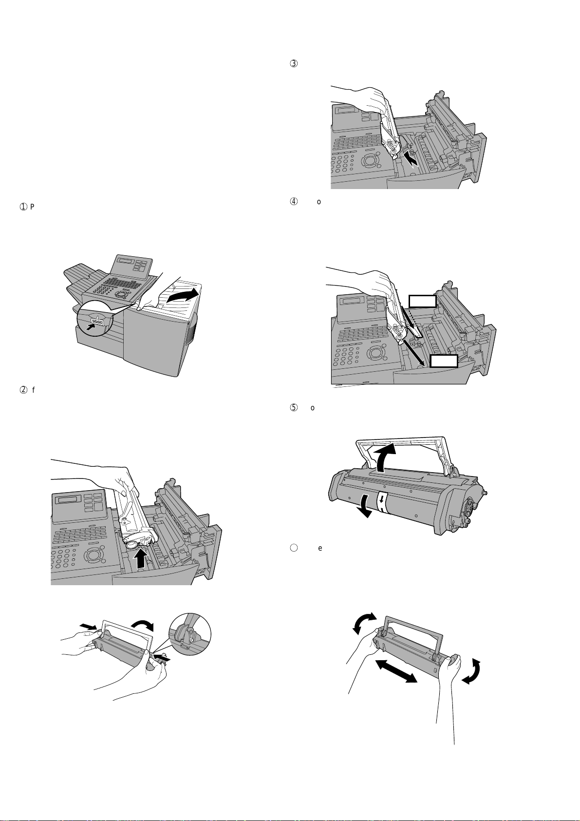
3. Installing the printer cartridges
(Toner cartridge: FO-50ND)
(Drum cartridge: FO-47DR)
Follow the steps below to install or replace the toner and drum cartridges.
• The initial starter toner cartridge included with the fax machine can
print approximately 3000 letter-size pages (4% coverage of each
page; continuous printing).
• The replacement toner cartridge (FO-50ND) can print approximately
6000 letter-size pages.
• The drum cartridge (FO-47DR) can print approximately 20,000 let-
ter-size pages.
1
Press the cover release to open the print compartment cover.
• Caution! The fusing unit inside the print compartment becomes
very hot during operation. Be careful not to touch the
inside of the compartment.
3
If you are replacing the drum cartridge, remove the old cartridge and
dispose of it according to local regulations.
4
Remove the new drum cartridge from its packaging. Insert the drum
cartridge into the print compartment.
• Caution! Excessive exposure to light will damage the drum
cartridge. Install the cartridge promptly after removing it
from its packaging.
• Make sure the drum cartridge is inserted in as far as it will go.
BLUE
2
If you are replacing the toner cartridge, remove the old cartridge and
dispose of it according to local regulations.
Go directly to STEP 6 if you are only replacing the toner cartridge
and not the drum cartridge.
• If you are replacing the drum cartridge but not the toner cartridge,
remove the toner cartridge and place it on a sheet of paper.
GREEN
5
If you are installing a new toner cartridge, remove the new toner cartridge from its packaging. Remove the tape from the cartridge and
then open the cartridge handle so that it stands straight up.
6
Shake as indicated by the arrows to distribute the toner evenly within
the cartridge.
• If the toner is still lumpy after shaking, the gears in the cartridge
may make a noticeable sound when the print compartment cover
is closed after installing the cartridge. This is normal and does not
indicate a problem.
To make the cartridge more compact for disposal, press the buttons on
the ends of the handle and fold the handle down.
1 – 5
Page 9
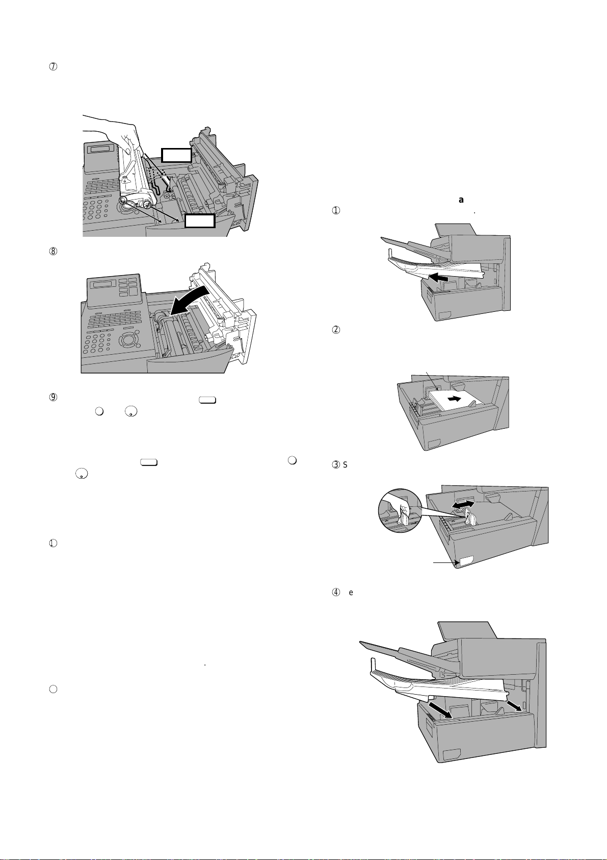
7
Red line
Attach a letter or
legal label here to
indicate the paper size.
Hold the toner cartridge by the handle and insert it into the print compartment.
• Make sure the toner cartridge clicks into place.
• The handle can be left standing up.
BLUE
GREEN
8
Close the print compartment cover.
FO-4400U
FO-CS1
4. Loading printing paper
You can load up to 250 sheets of letter or legal paper (max. 20 lbs.) in
the paper tray.
• A paper cassette is available as an option. Up to 500 sheets of letter
or legal paper can be loaded in the paper cassette. To have the cassette installed, consult your dealer.
Important: Do not use the back side of paper that has already been
printed on.
Note: If you need to add paper to the tray or cassette while paper still
remains, remove the remaining paper and combine it into a single
stack with the new paper.
Loading paper in the paper tray
Remove the received document tray.
1
2
Insert a stack of paper into the tray, print side up.
• Important! The stack of paper must not be higher than the red line
on the paper tray.
9
Reset the drum counter by pressing
overlay), 3, and
START/
ENTER
.
LIFE
(flip up the Rapid Key
V
• Note: The toner counter automatically resets each time you re-
place the toner cartridge. There is normally no need to reset the toner
counter manually . Should you find it necessary to manually reset the
toner counter, press
START/
ENTER
and
.
Note: The print compartment cover may become noticeably warm if a
large number of pages are successively printed. This is normal and does
not indicate a problem in the machine.
F
When to replace the toner cartridge
When the toner cartridge nears empty (about 100 pages can still be
printed), the toner cartridge indicator on the operation panel will blink.
When the toner cartridge is empty, the toner cartridge indicator will
light steadily and REPLACE TONER will appear in the display . Printing will no longer be possible. Use the following replacement toner
cartridge.
Sharp FO-50ND toner cartridge
Hint:
When the toner cartridge nears empty, try taking it out of the machine and shaking it. This may increase the number of pages that
can be printed before the toner runs out.
LIFE
(flip up the Rapid Key overlay), 2 ,
V
3
Squeeze the paper guide and move it to match the length of the
paper you are loading.
4
Replace the received document tray.
• The received document tray must be attached for the fax machine
to operate properly.
G
When to replace the drum cartridge
When the drum cartridge nears the end of its life, the ALARM indica-
tor on the operation panel will blink and DRUM LIFE REACHED will
appear in the display. (this message appears when approximately
1000 pages can still be printed). Use the following replacement drum
cartridge.
Sharp FO-47DR drum cartridge
1 – 6
Page 10
FO-4400U
FO-CS1
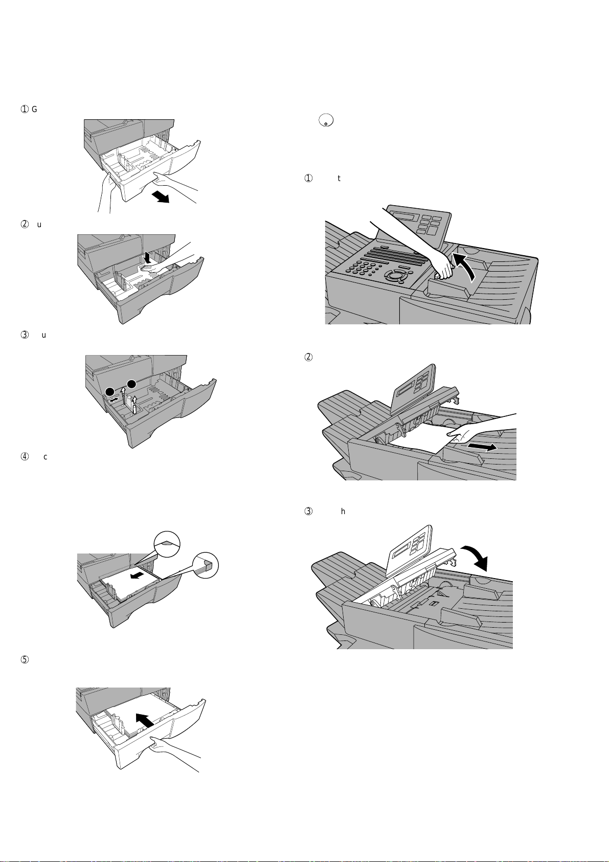
Loading paper in the paper cassette (if installed FO-CS1)
Note: To use A4 paper in the paper cassette, you must have a service
technician adjust the cassette.
1
Grasp the hand-hold on the cassette and pull the cassette out until it
stops.
2
Push the pressure plate down until it locks into position.
3
Squeeze the paper guide and pull up to move it to the appropriate
holes for the length of the paper. Push the guide down into the holes.
5. Clearing paper jams
Clearing a jammed document
If the original document doesn’t feed properly during transmission or
copying, or REMOVE ORIGINAL(S) appears in the display , fist try press-
START/
ENTER
ing
. If the document doesn’t feed out, open the operation panel
and remove it.
Important: Do not try to remove a document without opening the opera-
tion panel. This may damage the feeder mechanism.
1
Open the operation panel.
• Squeeze the release marked PANEL RELEASE and pull up.
2
Remove the document.
1
2
4
Place a stack of paper in the cassette, print side up.
• Make sure the stack of paper is not higher than the two tabs on the
paper guide and the two metal tabs. If it is, remove some of the
paper.
• If you find it difficult to load the paper, remove the cassette from the
machine. (Pull the cassette out as far as it will go, grasp the left
side of the cassette with your left hand, and then lift it up and out
with both hands.)
5
Push the cassette back into the machine, making sure it clicks into
place.
3
Close the operation panel, making sure it clicks into place.
1 – 7
Page 11
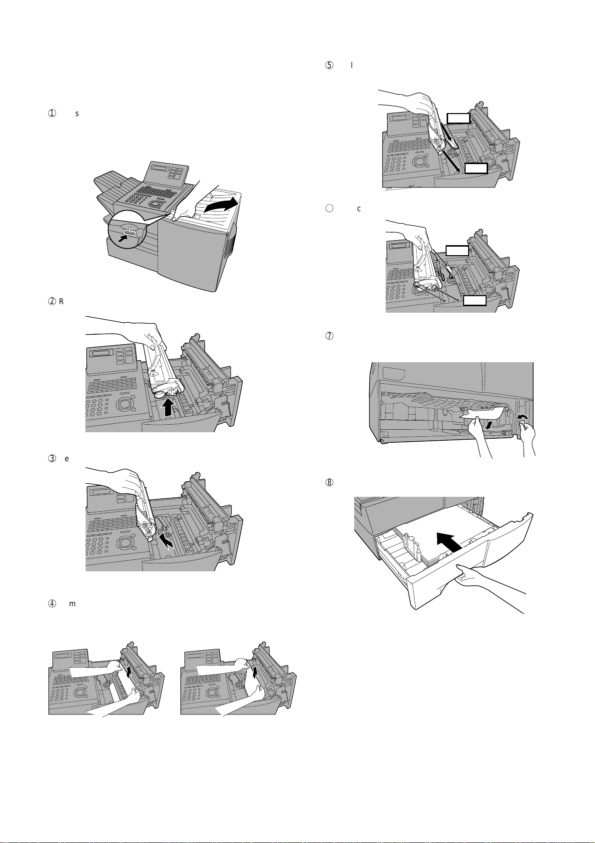
Clearing a jammed printing paper
GREEN
BLUE
If the printing paper jams, PAPER JAM will appear in the display . Follow
the steps below to clear the jam.
1
Press the green release and open the print compartment cover.
• Caution! The fusing unit inside the print compartment becomes
very hot during operation. Be careful not to touch the
inside of the compartment.
2
Remove the toner cartridge and place it on a sheet of paper.
FO-4400U
FO-CS1
5
Replace the drum cartridge.
• Make sure the drum cartridge is inserted in as far as it will go.
BLUE
GREEN
6
Replace the toner cartridge and then close the print compartment
cover.
3
Remove the drum cartridge.
4
Remove the jammed paper.
• Make sure no torn pieces of paper remain in the print compartment
and rollers.
7
If you have a paper cassette and the display still indicates that paper
is jammed, pull out the cassette and remove the jammed paper.
8
Replace the paper cassette.
OR
1 – 8
Page 12

FO-4400U
2
1
A
1
3
2
FO-CS1
6. Installing the paper cassette (FO-CS1)
Installing the second paper cassette
Important: Be sure to turn off the power and unplug the power cord
before proceeding.
1
Press the cover release to open the print compartment cover.
2
Remove 6 screws from the rear cover.
Remove the small cover on the left side of the rear cover, and then
remove the screw underneath. Remove the rear cover.
5
Place the machine on top of the cassette.
1. Insert the cable guide into the cut-out in the edge of the metal
plate, and then fold it in half and hook the top and bottom edges
together.
2. Insert the 15pin cable through the ferrite core, and then connect
the cable to the connectors on the machine and the cassette as
shown. Position the ferrite core in the gap between the bottom
left-hand corner of the circuit board and the side of the
compartment. Insert the cable into the cable guide, and then
insert the remainder of the cable into the slot in the cassette
below the cable guide. Tie the wires with the band.
3
Remove 2 screws from the right cover of the machine.
From inside the print compartment, push the 3 tabs indicated in the
blowup out. (Note: The blowup shows the inside of the print compartment.) Insert your left index finger in between the cover and the machine as shown, and then close the print compartment cover. With
your index finger still inserted, grasp both sides of the cover and pull
it off.
4
Remove the packing material and tape from the paper cassette.
6
Replace the small cover over the circuit board and secure it with a
10 mm screw.
P
7
Attach the support plates to the right side of the machine.
1. Remove the indicated screw.(In Step 8 below, replace it in the
same hole.)
2. Mount the large plate, making sure that the guides fit into the holes
as shown.
3. Mount the small plate, making sure that the guides fit into the holes
as shown.
1 – 9
Page 13
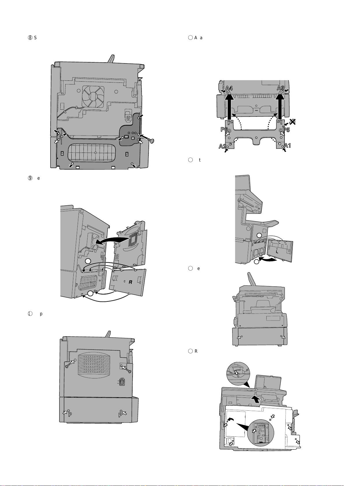
8
P
P
Secure the plates with screws as shown. Use 6 mm screws for the
holes marked with “A”, and 10 mm screws for the holds marked with
“”P”. Secure the screws in the order indicated by the numbers.
A4
A3
A3
P3
A2
9
Replace the right side cover on the machine, inserting the tabs into
A4
A4
P4
A1
the holes.
Attach the longer cassette cover to the right side of the cassette,
inserting the tabs into the holes (first top, then bottom).
FO-4400U
FO-CS1
G
Attach the support plate to the left side of the machine, inserting the
top edges of the plate under the machine housing. Make sure that
the guides fit into the holes as shown.
Secure the plate with screws as shown. Use 6 mm screws for the
holes marked with “A”, and 10 mm screws for the holes marked with
“P”. Secure the screws in the order indicated by the numbers.
(Note that the top hole on the right does not require a screw.)
H
Attach the shorter cassette cover to the left side of the cassette, inserting the tabs into the holes (first top, then bottom).
1
2
F
Replace the screws in the side cover on the machine.
Secure the cassette cover with two 10 mm screws.
A
A
P
A
1
2
I
Secure the cassette cover with two 10 mm screws.
J
Replace the rear cover (replace the screw under the small cover on
the left side of the rear cover first, and then replace the small cover).
A
A
P
P
A
P
A
1 – 10
Page 14
FO-4400U
CONTRAST
BROADCAST
START/
ENTER
SPEAKER
FO-CS1
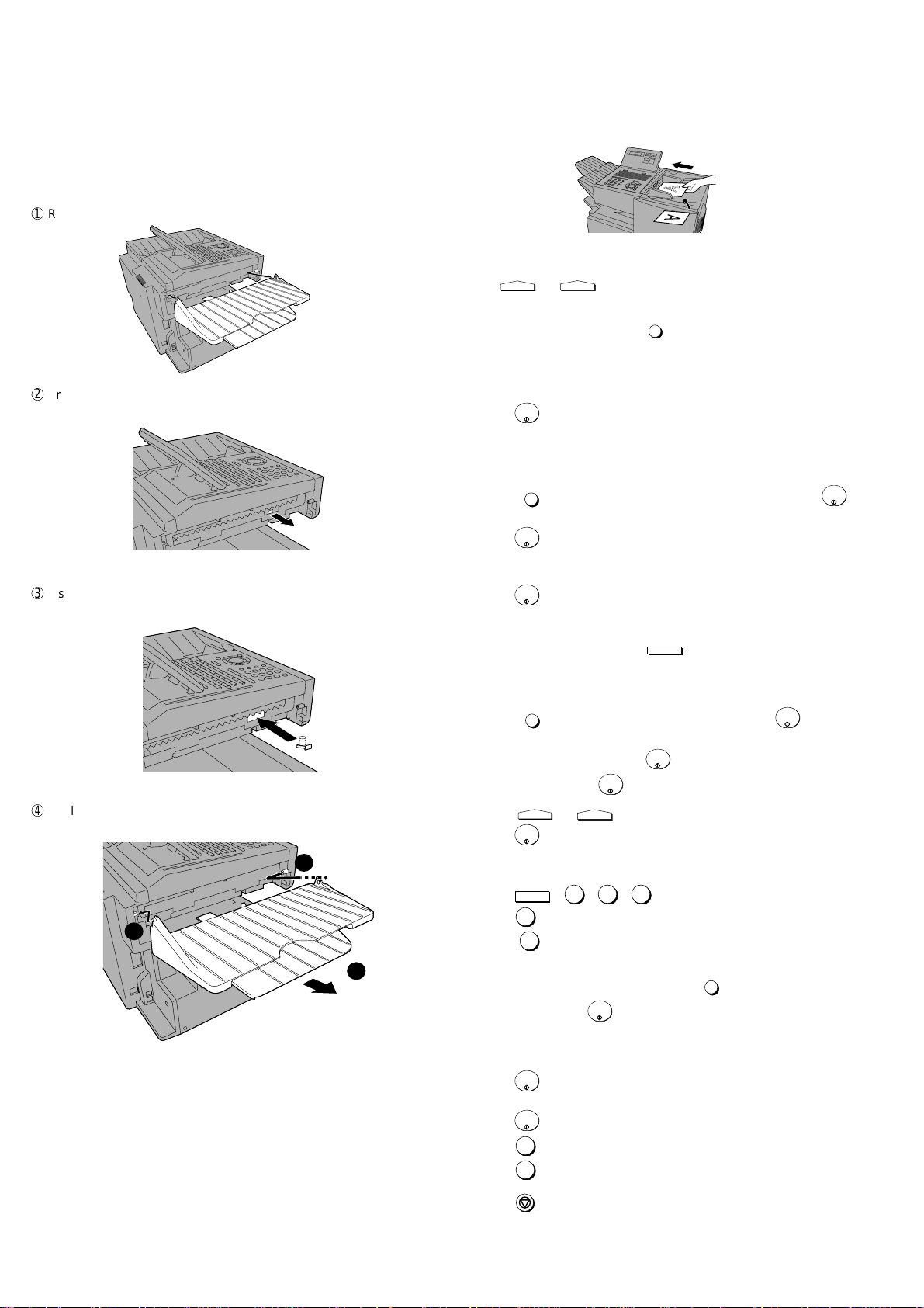
7. Replacing the Verification Stamp (FO-45VS)
If you are using the Verification Stamp function, you will need to replace
the ink cartridge in the stamp unit when it runs out of ink (when the
stamped mark on original documents becomes faint). A new ink cartridge can be obtained from your dealer.
1
Remove the ADF exit tray.
2
Press down on the protruding tab of the green ink cartridge and pull
the cartridge out with your fingers.
3
Insert the new ink cartridge into the machine (make sure that the tab
is facing out).
4
Replace the ADF exit tray.
[6] Quick reference guide
SENDING FAXES
Place your document (up to 50 letter-size pages) face down in the document feeder.
(Note: For Normal Dialing and Direct Keypad Dialing, you can also load
the document after dialing the number.)
RESOLUTION
Press
Normal Dialing
1. Lift extension phone or press
2. Dial the fax number (if using an extension phone, dial on the extension phone keypad).
3. Wait for the reception tone (if a person answers, ask them to press
their Start key).
4. Press
Rapid Key Dialing
1. Press the desired Rapid Key.
Speed Dialing
1. Press
if you entered a 1-digit number).
2. Press
Direct Keypad Dialing
1. Dial the fax number.
2. Press
BROADCASTING
1. Load the document and press
2. Dial destination numbers:
Press a Rapid Key.
Press a Group Key.
Press
plete entry if only one digit is entered).
Enter a full number and press
3. When finished, press
4. Press
5. Press
or
if needed.
.
START/
ENTER
.
SPEED DIAL
and enter the desired Speed Dial number (press
START/
ENTER
.
START/
ENTER
.
.
SPEED DIAL
and enter a Speed Dial number (press
START/
ENTER
.
START/
ENTER
.
RESOLUTION
START/
ENTER
CONTRAST
or
if needed.
.
START/
ENTER
to com-
1
STORING AUTO DIAL NUMBERS
1. Press
MENU
, 3 , 0 , 1 .
2. Press 1 to store a number.
2
3
(Press 2 to clear a number.)
3. To store a Rapid Key number, press the desired Rapid Key.
To store a Speed Dial number, press
START/
from 1 to 75 (press
ENTER
if you entered a 1-digit number).
SPEED DIAL
and enter a number
(If clearing a number, select it as explained above and then perform
Step 7 and 9.)
4. Enter the full fax number.
START/
5. Press
ENTER
.
6. Enter a name by pressing the letter keys.
START/
7. Press
ENTER
.
8. Press 1 if this is a Chain Dial number.
Press 2 if this is a regular number.
9. Press
STOP
repeatedly to exit.
1 – 11
Page 15
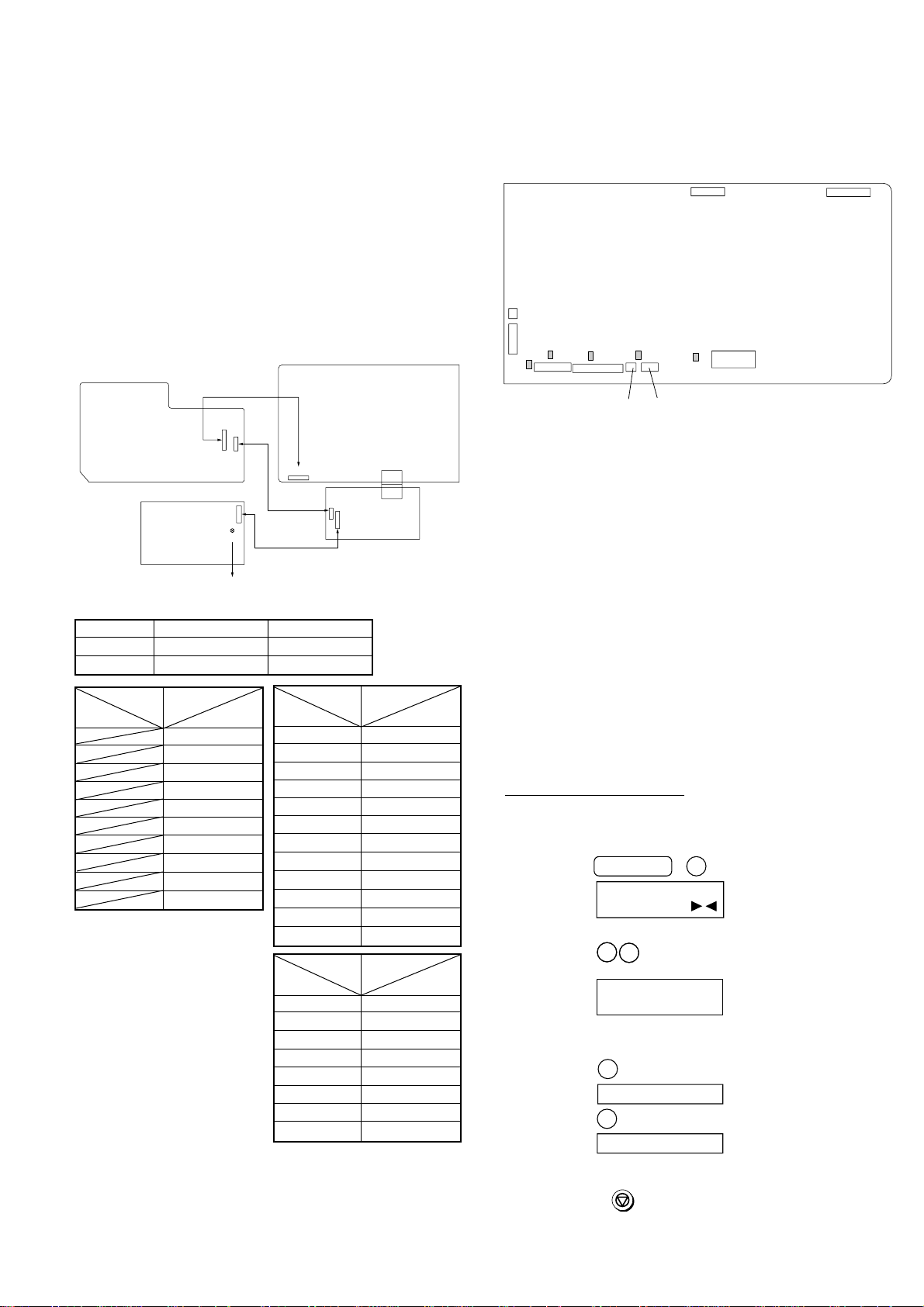
CHAPTER 2. ADJUSTMENTS
CONTROL PWB
(TOP SIDE)
CNLIU1
CNSP1
CNSEN1
CNCIS1
CNPN1
CNSTP1
F1/F2/F5:Top side
F100/F101:Bottom side
CNTXM1
IC3
1
1
8
10 1
1
1214
27
228
F1
F2
F5 F100
F101
2
CNPW1
12 1
[1] Adjustments
General
Since the following adjustments and settings are provided for this model,
make adjustments and/or setup as necessary.
1. Adjustments
Adjustments of output voltage (FACTORY ONLY)
1. Install the power supply unit in the machine.
2. Set the recording paper and document.
3. When the document is loaded, power is supplied to the output lines.
Confirm that outputs are within the limits below.
Output voltage settings
FO-4400U
FO-CS1
2. IC protectors replacement
ICPs (IC Protectors) are installed to protect the CIS unit, panel PWB
unit, TX motor drive circuit and verification stamp drive circuit. ICPs protect various ICs and electronic circuits from an overcurrent condition.
The location of ICPs are shown below:
POWER
SUPPLY
PWB
Output Voltage limits Note
+5V MAIN 4.947V~5.25V CN5 7pin ↔ 8pin
+24V SUB 23.04V~24.96V CN5 1pin ↔ 2pin
Connector CN4
No.
Pin No. CN1
1 11 +5V
2 10 CH LREM
39T VR
4 8 T MON V
5 7 T MON I
6 6 B VR
7 5 V REM
8 4 C MON
93MG
10 2 +24V
HIGH VOLTAGE
PWB
CN5
[DO NOT TOUCH!]
1
1
CN1
12
CN1
VR51
8
1
10
CNPW1
112
Fig. 1
Connector CN5
No.
Pin No. CNPW1
Connector CN1
No.
Pin No. CN7
CONTROL PWB
CNPRT1
130
130
CN7
8
10
1
CN4
PRINTER PWB
1
CN1
1 +24V SUB
2MG
3MG
4MG
5 +24V MAIN
6 +24V MAIN
7 +5V MAIN
8DG
9DG
10 DG
11 +5V MAIN
12 +5V MAIN
1 +24V MAIN
2MG
3DG
4DG
5 +5V MAIN
6 +5V MAIN
7 HEATER ON
8 H-RELAY OFF
Fig. 2
(1) F1 (ICP-S0.5) F2 (ICP-S1.0) is installed in order to protect IC’s from
an overcurrent generated in the CIS unit. If F1 or F2 are open,
replace it with a new one.
(2) F5 (ICP-S1.0) is installed in order to protect IC’s from an overcurrent
generated in the panel PWB unit. If F5 is open, replace it with a
new one.
(3) F100 (ICP-S1.0) is installed in order to protect IC’s from an
overcurrent generated in the verification stamp drive circuit. If F100
is open, replace it with a new one.
(4) F101 (ICP-S1.8) is installed in order to protect IC’s from an
overcurrent generated in the TX motor drive circuit. If F101 is open,
replace it with a new one.
In addition to the replacement of F1, F2, F5, F100 and F101, the
factor causing F1, F2, F5, F100 and F101 to open must also be
repaired. If not, F1, F2, F5, F100 and F101 will open again.
Replacement parts
ICP-S0.5 (Sharp code: VHViCPS05//-1)
ICP-S1.0 (Sharp code: VHViCPS10//-1)
ICP-S1.8 (Sharp code: VHViCPS18//-1)
3. Settings
(1) Dial mode selector
OPTION SETTING: DIAL MODE (Soft Switch No. SW2 DATA No. 1)
Use this to set the fax machine to the type of telephone line you are on.
• The factory setting is "TONE".
(step 1) Select "OPTIONAL SETTING".
KEY:
DISPLAY:
(step 2) Select "DIAL MODE".
(step 2) Select "DIAL MODE".
KEY:
KEY:
DISPLAY:
DISPLAY:
(step 3) Select, using "1" or "2".
KEY:
DISPLAY: TONE SELECTED
KEY:
DISPLAY:
(step 4) End, using the "STOP" key.
KEY:
2 – 1
MENU 4
4:OPTIONAL SETTING
ENTER #(01-36, , )
2
2
2
2
22: DIAL MODE
22: DIAL MODE
1=TONE, 2=PULSE
1
2
PULSE SELECTED
STOP
Page 16
FO-4400U
FO-CS1
[2] Diagnostics and service soft switches
1. Operating procedure
Two kinds of diagnoses are supported.
1-1. Fax diagnosis
This diagnosis is concerned with the main body of fax which is used for
production and service support.
Entering the diagnostic mode
MENU
Press
display will appear.
MAIN:TA68
Then press the
and the key or select with the rapid key.
Enter the mode with the
(Diag
•
specifications)
MENU
9 8
START
9 8 7
7
, and
the
key. Select the desired item with the
START
key.
TA68
following
key
1-2. Print diagnosis
This diagnosis is concerned with the print which is used for production
and service support.
Entering the diagnostic mode
MENU
Press
display will appear.
PCU ROM VER.:
Then press the
key and the keyor select with the rapidkey.
Enterthe mode with the key.
(Diag•specifications)
MENU
01
02
9 8
START
9 8 6
START
START
6
, and
the
following
key. Select the desired item with the
START
PCU ROM Ver.:
START
AREA PRINT MODE 1
CHECK PATTERN 1
START
STARTA SOFT SWITCH MODE
B PRINT AREA
C ROM & RAM CHECK
D AUTO FEEDER MODE
E AGING MODE
F PANEL CHECK MODE
G OPTICAL ADJUST MODE
H PRODUCT CHECK
I
J
K
L
M
N
O CONF. PASSCODE
P
Q
R
S
T
U
V
W
START
START
START
START
START
START
START
START
START
START
START
START
START
START
START
START
START
START
START
START
START
START
SIGNAL SEND MODE
COMM. CHECK MODE
MEMORY CLEAR MODE
FLASH MEMORY CHECK
ALL FAX/TEL. ENTRY MODE
DEPT. PASSCODE
SIGNAL SEND MODE 2
MEMORY SET MODE
STAMP AGING MODE
DIAL TEST MODE
COPY DIAG MODE
LCD CHECK MODE
PERSONAL BOOK LIST
NO FUNCTION
03
08
09
START
START04
START05
START06
START07
START
START
START10
START11
START12
CHECK PATTERN 2
CHECK PATTERN 3
CHECK PATTERN 4
PAPER FEED AGING 1
PAPER FEED AGING 2
BIAS ADJUST MODE2
LIFE SET MODE
LIFE ALL CLEAR
LIFE ENTRY MODE
LIFE CLEAR MODE
Memory clear when power is turned on
Pressing the START and STOP keys, turn on the main power, and the
following message will be displayed.
MEMORY CLEAR ?
1 = ALL , 2 = IMAGE , 3 = NO
1 = All the data will be deleted including initially registered data.
2 = Delete the image file to be used in transmission. This will delete all
the data related to communication such as reserved transmission or
intercepting. However, the data initially registered will not be deleted.
3 = Memory will not be cleared and the machine enters stand-by mode.
X
START
NO FUNCTION
2 – 2
Page 17
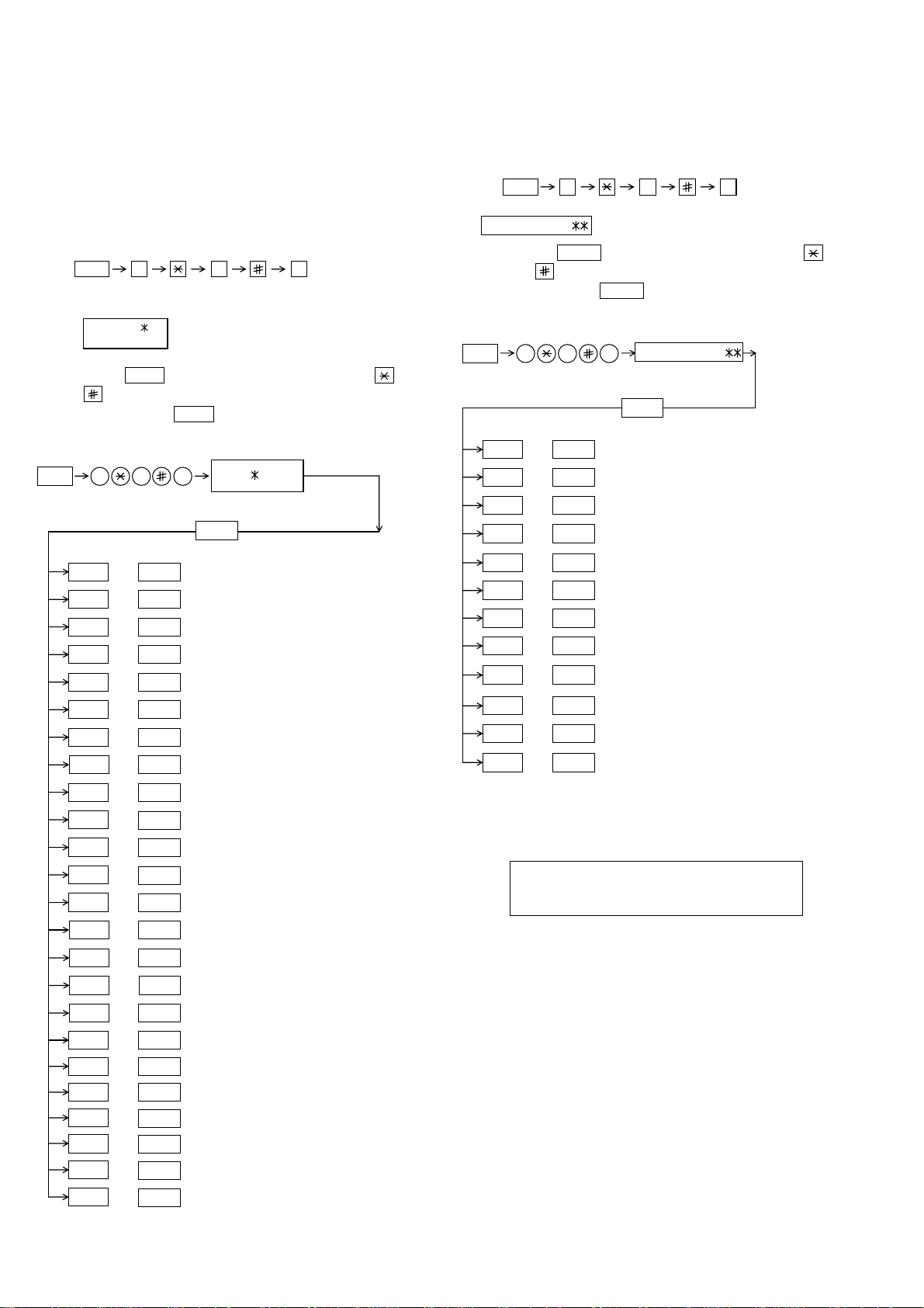
2. Diagnostic items description
ROM SRM DRM1 DRM2
• • • •
ROM SRM DRM1 DRM2
P P P E
Display during check Display after check
P=PASS E=ERROR
2-1. Fax diagnosis
A) Soft switch mode
In this mode, the soft switch are set and the soft switch list is printed.
Soft switch mode screen
S O F T S W I T C H M O D E
S W 0 1 = 0 0 0 0 0 0 0 0
8
Data
1
Switch number selection
1 2 3 4 5 6 7 :DATA No.
Switch
No.
• Press START key for setting of the next soft switch. If the soft
switch number is the final, pressing START key will exit the soft
switch mode.
• Enter two digits of a soft switch number to set the switch number.
If a switch number of nonexistent soft switch is entered, key error
buzzer sounds to reject the input.
S O F T S W I T C H M O D E
S W 0 1 = 0 0 0 0 0 0 0 0
Cursor
2
Data number selection
E N T E R L A S T D I G I T
S W 1
1 6
S O F T S W I T C H M O D E
S W 1 6 = 0 0 0 1 0 1 1 0
The cursor position shows the data to be set.
Pressing # key or → key moves the cursor to the right. If, however,
the cursor is on data number 8, pressing # key or → key shifts the
cursor to data number 1 of the next switch number. If the switch
number is the final, pressing # key or → key will exit the soft switch
mode.
Pressing key or ← key moves the cursor to the left. If, however,
the cursor is on data number 1, pressing key or ← key shifts the
cursor to data number 1 of the former switch number. If the switch
number is 1, pressing key or ← key will not move the cursor and
the error buzzer will sound.
3
Data setting method
Press the MENU key, and the data at the position of the cursor will be
reversed to 0 when it is 1, or to 1 when it is 0. (If the soft switch can
be changed at the bit (Refer to 6.), the error buzzer will sound with
the process not received.)
4
Outputting method of soft switch list
In the soft switch mode, press the REPORT key , and the soft switch
list will be output.
If the recording paper runs out or is clogged, the key error buzzer will
sound with the process not received.
5
Storage of data
In the following case, the data of the soft switches set will be stored.
• It is shifted to set the next soft switch by pressing the START
switch.
• It is shifted to set the next soft switch with the [#] key.
• It is shifted to set the last soft switch with the [ ] key.
• It is shifted to set another soft switch by inputting two digits as the
switch number. (When 2 digits are completely input.)
• Output of the soft switch list is started.
6
Inhibition of data change
(This is also applicable for the optional setting.)
In the following case, it is inhibited to change the data with the key
error buzzer.
• Switching ON/OFF of ECM during the use of image memory.
• OFF to ON of telephone billing function which is using the image
memory is used (Note: In the existing set, the telephone billing
code function is specified from OFF to ON when the timer system
communication (including the batch communication) is set.)
Here, the memory is usable when the telephone billing code function is on. It can be set from ON to OFF while the memory is
used. However, if setting is practically changed even once, it can
not be returned from OFF to ON.
FO-4400U
FO-CS1
• OFF to ON of department control function during use of image
memory.
(Note: In the existing set, the department control function is set
from OFF to ON when the timer communication (including the
batch sending) or the memory hold is set.)
• ON to OFF of continuous serial polling function when the con-
tinuous serial polling is started.
(Note: In the existing set, "ON to OFF of the continuous serial
polling function when the continuous serial polling is registered"
has been applied, but the conditions are now moderated. However, registration is impossible to the program of the new continuous serial polling when the continuous serial polling function is
OFF.)
• In addition, change of all soft switches during communication
B) Print area
According to the size of the specified sheet, the effective printing area is
printed.
C) ROM & RAM check
This is an item to check if the loaded memory device acts normally.
• The memory devices shown in the following table are checked.
• In case that an error occurs in the device check, the alarm buzzer
shown in the table sounds.
Check device and alarm buzzer
No. Device checked
1
2 SRAM <Short sounds> 2 times
3 Main D-RAM1 (*1) <Short sounds> 3 times <Long sounds>:
4 D-RAM2 (*2) <Short sounds> 4 times 1.0 sec.ON / 0.5 sec.OFF
5 ——
ROM (PROGRAM FLASH)
*1: Work memory (SDRAM 8MB)
*2: Page memory (SDRAM 8MB)
(Example of display) In case that DRAM2 is erroneous.
After the check is complete, the result is outputted.
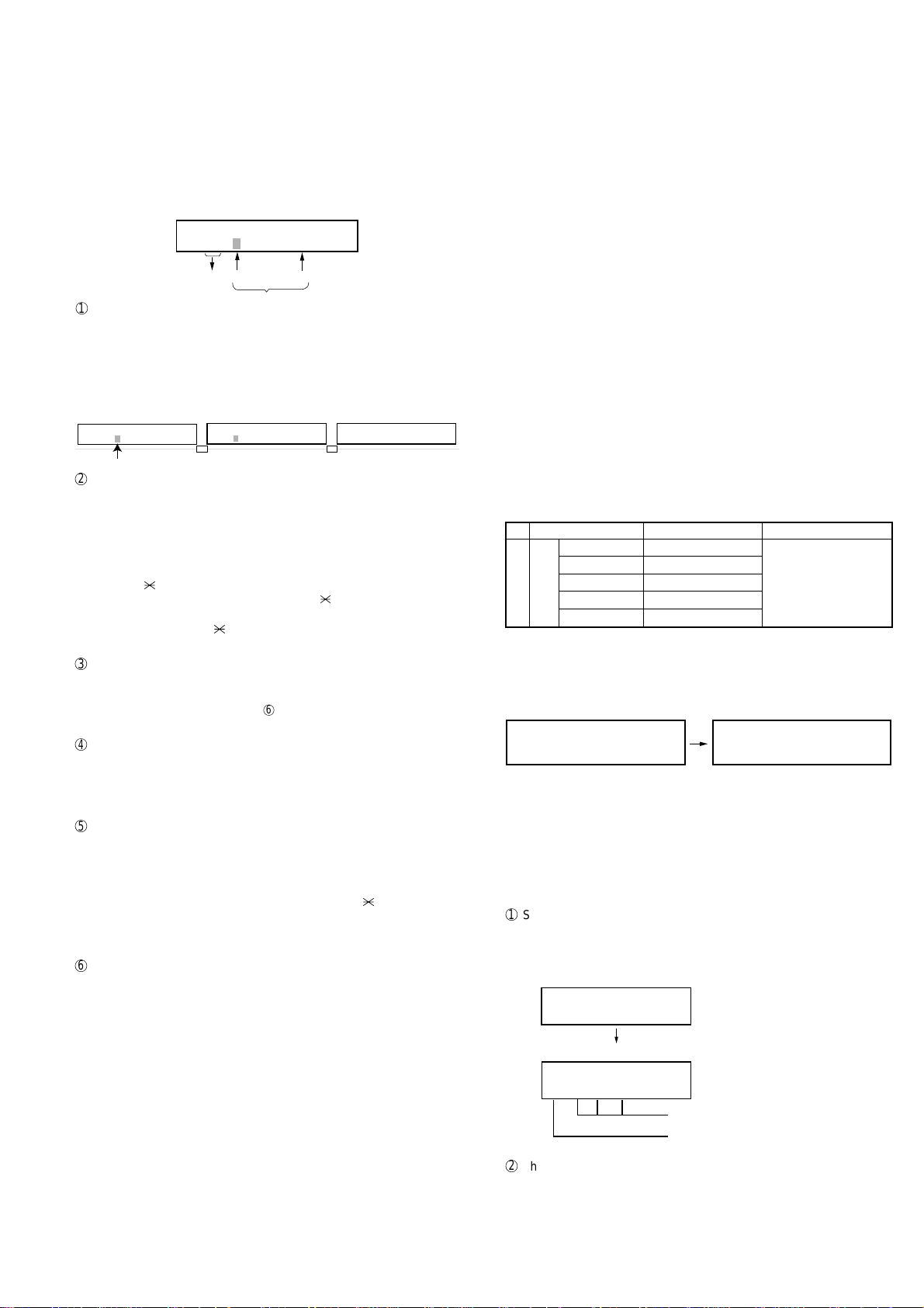
D) Auto feeder mode
By executing the document insertion and discharge, the automatic feeding function can be checked. And the document sensor can be checked
as well.
1
Set the document
Before pressing the “START” key , only the document sensor check is
carried out. And as the document sensor is ON, the document size
(A4/B4) and the sensor information (A4/B4/ORG) are displayed.
AUTO FEEDER MODE
( )
After setup of the document
AUTO FEEDER MODE
B4 (A4 B4 ORG)
2
The automatic feeding starts by pressing the “START” key. This mode
ends when the document ends, and the result is printed.
Number of buzzer sound
<Short sound> 1 time <Short sound>:
Only the sensor which is
activated (fallen down) is displayed.)
The paper sheet size (A4/B4) is
displayed.
Remarks
0.5 sec.ON / 0.5 sec.OFF
2 – 3
Page 18

FO-4400U
FO-CS1
E) Aging mode
This is a mode to execute the copying action and the check pattern
printing action once every 60 minutes and continue the action until 10
sheets are outputted in total.
1
The printing action on the 1st sheet starts by pressing down the
“START” key and entering the mode. When document is set at the
time of the mode start-up the copy action is carried out, and when
the document is not set the “check pattern 1” of the print dialog is
printed.
2
The number of printouts is displayed after printing.
F) Panel check mode
This is to check that each key acts normally and this is displayed on the
LCD according to the key input. And during execution, the document
reading lamp is ON. After inspection start, the LEDs light on sequentially.
At the mode end with the “STOP” key, all of them go OFF. As to the test
result, it is printed out after the mode end.
When the “NUMERIC” key is pressed during the panel check execution, sending of the DTMF signal corresponding to the key starts,
and when another key is pressed sending of the DTMF signal stops.
• After inputting all the keys, input the “STOP” key at last, and then the
result is displayed.
a) In case that all the keys are pressed.
PANEL CHECK MODE
ALL KEY OK !!
• After the mode end, the test result is printed.
b) In case that there is a key that is not pressed.
PANEL CHECK MODE
KEY ERROR !!
• At the time of NG, the keys that are not pressed are displayed
sequentially, and it becomes the mode to input the key again.
• With the “STOP” key, the re-check is complete.
• After the mode end, the test result is printed.
G) Optical adjust mode
The optical system is adjusted.
• By pressing down the “START” key, the document reading lamp “100%:
ON” is turned ON.
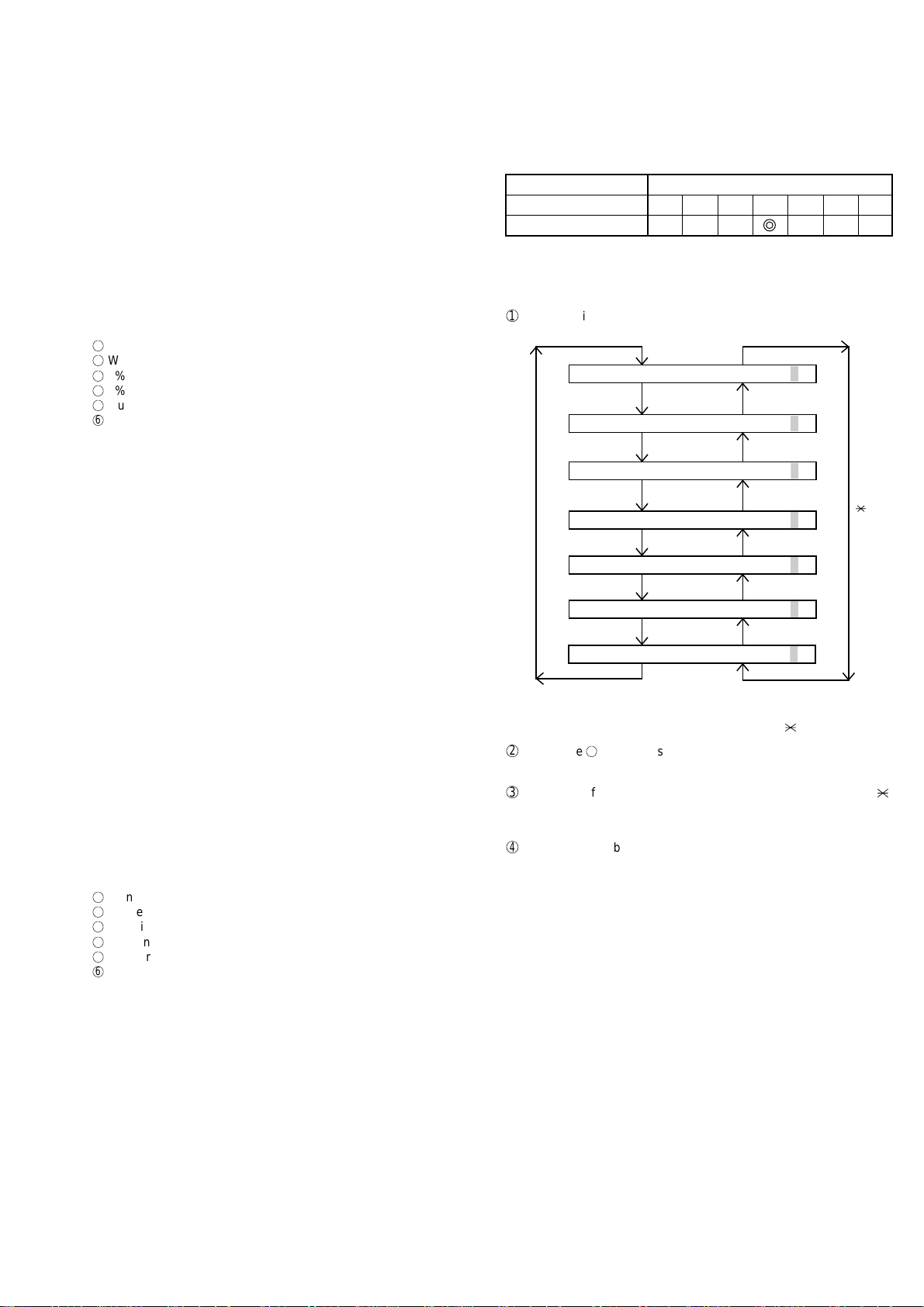
I) Signal send mode
After shift to the mode, press the START key, and the signals will be
transmitted in the following sequence.
It can be used to check the modem and so on.
[ 1] No signals
[ 2] 4800BPS (V. 27ter)
[ 3] 14400BPS (V. 33)
[ 4] 12000BPS (V. 33)
[ 5] 14400BPS (V. 17)
[ 6] 12000BPS (V. 17)
[ 7] 9600BPS (V. 17)
[ 8] 7200BPS (V. 17)
[ 9] 9600BPS (V. 29)
[10] 7200BPS (V. 29)
[11] 4800BPS (V. 29ter)
[12] 2400BPS (V. 29ter)
[13] 300BPS (FLAG)
[14] 2100Hz (CED)
[15] 1100Hz (CNG)
J) Comm. check mode
1
Turn on the Line Monitor. (SW7 No.7, SW37 No.7)
2
Turn off the Cover Sheet Function. (SW2 No.6, SW32 No.6)
3
Set Line Equivalence at 0 km. (SW8 No.1/No.2, SW38 No.1/No.2)
After the check, it is necessary to be sure to return the aforementioned
soft switches into the initial state.
(Clear the memory with the diagnosis.)
K) Memory clear mode
Clear the back-up memory to initialize the soft switches.
The Flash Memory will be initialized. Then, the initialized list be output.
1
Memory clear is executed.
2
The result that says initialized is printed.
NOTE: The life system counter is not cleared.
H) Product check
This is a dialog used in the production process and a mode to execute a
specific mode in the series of the flow.
After the mode end, the rest result as to the checked items is printed.
• After moving to the mode, the following actions are sequentially ex-
ecuted.
1
Memory clear (Same as Diagnosis K)
2
Panel check (Same as Diagnosis F)
3
ROM & RAM test check (Same as the Diagnosis C)
4
Test result print
Memory clear printing
Panel check result printing
ROM & RAM test result printing
5
Print area (The specification of each item is the same as the specifi
cation of the simple mode.)
2 – 4
Page 19
L) Flash Memory check
This is a mode to check that the flash memory acts normally. The flash
memories shown in the following table are checked.
No. Flash memory
1
2
3
4 ——1.0 sec.ON / 0.5 sec.OFF
5 ——
NOR-Flash (Standard)
NAND-Flash (Standard)
NAND-Flash (Option)
Number of buzzer sound
<Long sound> 1 time <Short sound>:
<Long sounds> 2 times
<Long sounds> 3 times <Long sounds>:
Remarks
0.5 sec.ON / 0.5 sec.OFF
• NAND-Flash (optional) is valid only when the optional memory is
mounted.
1
The NOR flash memory test is executed.
NOR FLASH CHECK
S — — — — — — — E
2
The concerned alarm buzzer sounds only when the error occurs.
3
The NAND flash memory test is executed.
NAND FLASH CHECK
S — — — — — — — E
4
The concerned alarm buzzer sounds only when the error occurs.
5
The result is printed.
NOTE:
• During operation of this diagnosis, dual operation is not possible at all.
• If this is excessively repeated, it will shorten the life of the flash memory.
M) All FAX/TEL. entry mode
This is a function to copy the FAX and TEL numbers registered in the
one-touch dialing (RAPID) key [01] to the all one-touch dialing (RAPID)
key and the all abbreviated number (SPEED DIAL) to simplify the FAX
and TEL number registration at the time of aging.
1
Copy the Fax and Tel numbers (including agency) registered in the
one-touch dialing (RAPID) key [01] to all one-touch dialing (RAPID)
key.
2
Copy the FAX and TEL numbers registered in the one-touch dialing
(RAPID) key [01] to the all abbreviated number (SPEED DIAL).
3
In case the chain dial is not set in the one-touch dialing (RAPID) key
[01], register the one-touch dialing (dialing) keys [02] – [59] and all
abbreviated number (SPEED DIAL) to the group number [01].
In case that the chain dial is set, do not create a group, but cancel
only the chain dial setting of the one-touch dialing (RAPID) key [01].
(All except for the one-touch dialing (RAPID) key [01], chain dial is
kept set.)
4
Enter all registered one-touch send (RAPID) keys and speed dial
numbers (SPEED DIAL) on the personal books [01] - [10].
Following this, set the password registration and the password
setting to ON, and set the TTI setting to OFF.
The call-receiver names and book names are specified as follows:
Rapid R XX XX : Rapid key send
SPEED DIAL S XXX XXX
Personal book BOOK XX XX : Book number
(The letters after 16th letter of the call-receiver’s name registered in the
one-touch dialing [01] are cut off.)
NOTE: Before entering this mode, FAX and TEL numbers must be reg-
istered in the one-touch dialing (RAPID) key [01].
(In case that they are not registered, or a program or a group is
registered, it is not executed.)
N) Dept. passcode
The department passcode list is printed.
O) Conf. passcode
The confidential passcode list is printed.
Differing from printing of one box alone soon after registration, the confidential passcodes of all boxes are printed.
: Speed dial number
FO-4400U
FO-CS1
P) Signal send mode 2
The signals concerned with V.34 & V.8 are checked.
After this mode is activated, press the START key, and the signals will
be sent in the following sequence.
It can be used to check the modem.
[ 1] No signal
[ 2] 33600BPS (V. 34)
[ 3] 31200BPS (V. 34)
[ 4] 28800BPS (V. 34)
[ 5] 26400BPS (V. 34)
[ 6] 24000BPS (V. 34)
[ 7] 21600BPS (V. 34)
[ 8] 19200BPS (V. 34)
[ 9] 16800BPS (V. 34)
[10] 14400BPS (V. 34)
[11] 12000BPS (V. 34)
[12] 9600BPS (V. 34)
[13] 7200BPS (V. 34)
[14] 4800BPS (V. 34)
[15] 2400BPS (V. 34)
[16] 0 - 300BPS (V. 34)
[17] ANSam
Q) Memory set mode
The set and dump list of the memory content is output.
MEMORY SET MODE
AD = 00000000
Cursor
• The address (8 digits (P) generally including the bank information is
input, and the data of 2 digits is continuously input.
Inputting is done in the hexadecimal mode. The ten-key is used for 0
through 9, and the alphabetic keys A (RAPID 01 through 06) are
used for A through F.
MEMORY SET MODE
AD = A02800F6 DATA = 0B
• During data inputting, the address can be moved forward and back-
ward one byte by one byte with " " and "#". (The address prior to the
address 0 is looped as the maximum address.)
• The Validity of the address is not checked. Accordingly , writing/ read-
ing operations are possible in the address of the memory not assigned, the address of ROM and so on.
(However, as practical, writing is not done, and the data content runs
short each reading.)
Though writing is possible in the flash memory, a little time is required.
It is also necessary to take care that the life of the flash memory is
excessively shortened if much data is written in the flash memory.
Since it may run away depending the written content, take minute
care for the writing address.
• When the REPORT key is input, the memory dump list is produced
from the displayed address (here, it is limited at the 16-byte boundary address (address with end 0) which does not exceed the specified address and is just in front.). The dump list is output to a maximum of 99 pages. If any data of one page can be repeatedly developed and printed, the list is sufficient. But it is not desired that the
content of plural pages are developed in the memory once and are
then printed. If the STOP key is pressed, it will pass to the diagnosis
after the page which is now being printed is completed printed.
If the address exceeds the maximum address, it will return to the
address 0 and printing will be continued.
2 – 5
Page 20
FO-4400U
1
2
3
4
5
6
7
8
9
FO-CS1
R) Stamp aging mode
This is a mode to execute the continuous drive aging of the Verification
stamp.
1
Set the document and press down the “START” key and the
continuous drive of the Verification stamp starts.
2
Send the document at the interval of 10 mm and stamp the
Verification stamp continuously. The total number of times of
Verification stamp printing after entering this mode is displayed on
the display.
• Displayed screen during execution
STAMP AGING
TIMES = 13 PAGES = 1
2-2. Print diagnosis
Rapid key 01: Area print mode 1
The effective printing area frame is printed in the specified sheet size.
Print total number
of times
3
By pressing down the “STOP” key during the action, or when no
more document is left, the continuous drive of the Verification stamp
stops.
NOTE:
Page number
• In case that the document is not set, this cannot be executed.
• The normal action aging that one V erification stamp is pressed on one
sheet of document is executed in the normal copying.
S) Dial test mode
The mode is used to inspect whether dialing is accurate in two kinds of
dial modes . All data which can be dialed in this mode are automatically
called up in both PB mode and DP mode.
[In case that 2 line optional is not mounted.]
1
Turn on CML, and dial the following in the PB mode.
1, 2, 3, 4, 5, 6, 7, 8, 9, , 0, #
2
Dial the following in the DP mode.
1, 5, 9, 0
3
After dialing, turn off CML.
NOTE:
This mode uses the ordinary auto dial. (Accordingly, the signal sending
time and minimum pause are all the same as ordinary.
The measurement result in this mode is completely all the same as in
the ordinary dial mode.)
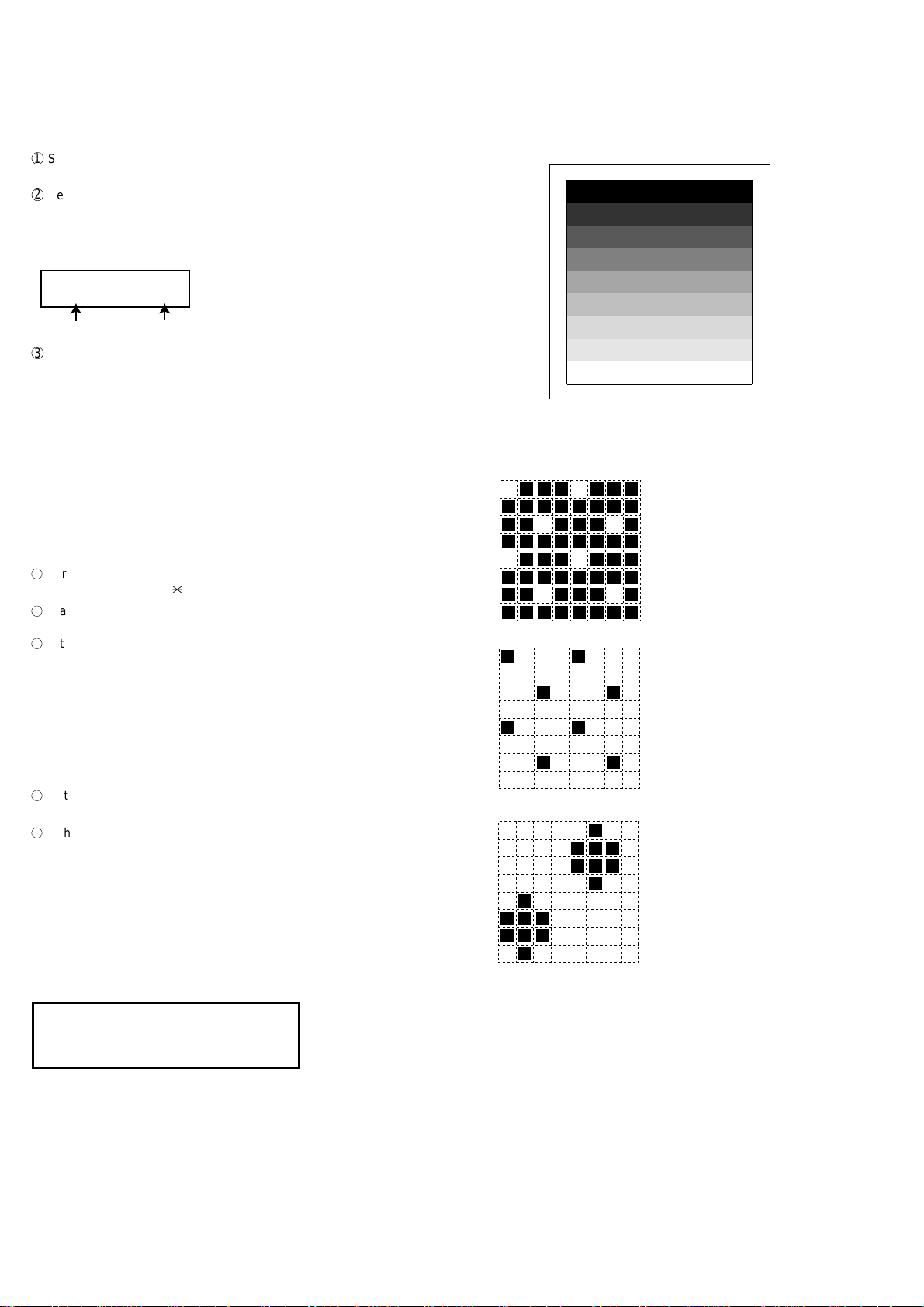
T) Copy diag mode
This mode is for automatic mode selection of copy to reduce the time for
treatment at the time of production.
1
Set 2 sheets of document. (No problem if there are 2 sheets or
more.)
2
3 sheet continuous copy: 1st sheet in the FINE AUTO
2nd sheet and after that are copied in the
H-TONE DARK.
NOTE:
Input of the image quality and the darkness keys is invalid in this mode.
The data pattern used here are as follows and 1 data 30 mm is printed.
1. [Full black pattern]
2. [Intermediate tone 2 pattern]
The left pattern is repeated.
3. [Intermediate tone 1 pattern]
The left pattern is repeated.
4. [Mesh point pattern]
The left pattern is repeated.
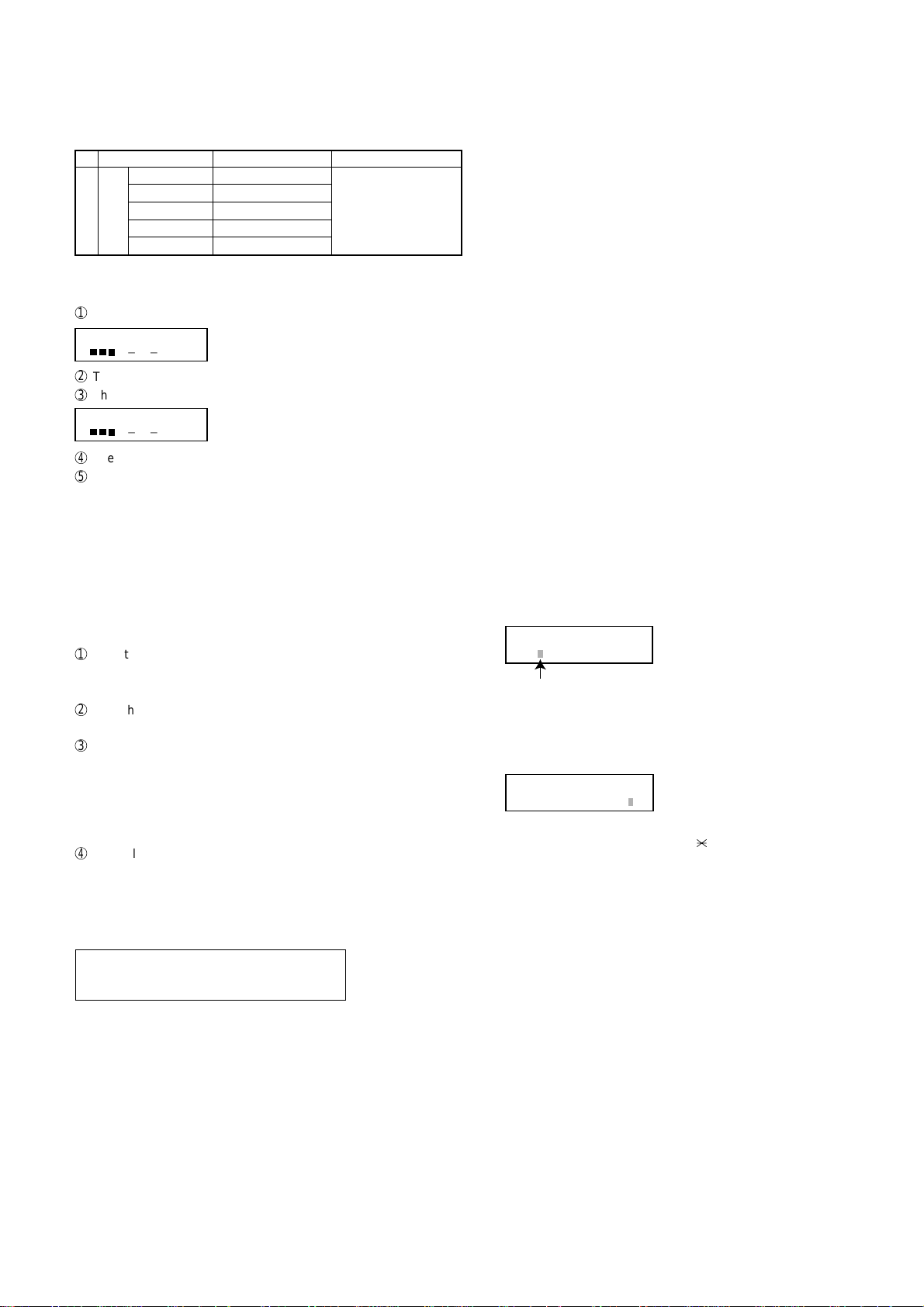
U) LCD check mode
This is an item to check that the LCD acts normally.
[In case of a 2 lines LCD]
Display “H” to all the digits. (20 letters x 2 lines)
HHHHHHHHHHHHHHHHHHHH
HHHHHHHHHHHHHHHHHHHH
V) Personal book list
The PASSCODE of the personal book 00 to 10 are output.
W) No function
X) No function
5. [Longitudinal strip 2 pattern]
Black 2 dot and white 2 dot are repeated in line.
6. [Lateral strip 2 pattern]
Black 2 line and white 2 line are repeated.
7. [Longitudinal strip 1 pattern]
Black 1 dot and white 1 dot are repeated in line.
8. [Lateral strip 1 pattern]
Black 1 line and white 1 line are repeated.
9. [Full White pattern]
2 – 6
Page 21
MACH I NE
DRUM
L
LIFE
LIFE
IFE1
= 0123
FEEDER L I FE=
=
=
LIFE2
=
LIFE3
=
0
key
# key
001230
001230
001230
001230
001230
0
FEEDER L I FE= 001230
Rapid key 02: Check pattern 1
The lateral stripe 2 pattern is printed on one sheet.
(Black 2 line and white 2 line are repeated.)
Rapid key 03: Check pattern 2
The lateral stripe 2 pattern is printed on multiple pages.
Press the STOP key to end the printing.
Rapid key 04: Check pattern 3
The intermediate tone 1 is printed on one sheet.
Rapid key 05: Check pattern 4
In this mode, 1 sheet is printed as to the square frame pattern for the
skew measurement.
Rapid key 06: Paper feed aging 1
The mode is used for aging related to the printing. In this mode, the
following modes are provided.
1
Blank paper aging mode (ALL WHITE AGING)
2
Whole black print aging mode (ALL BLACK AGING)
3
5% printing aging mode (5% AGING)
4
4% printing aging mode (4% AGING)
5
Outer frame check pattern
6
4% check pattern
After selecting the paper-pass aging mode in the print diagnosis mode,
input the number of each mode above with the ten-key, and the mode
will be executed. The detailed specifications of each mode are described
as follows. Here, the operation in each mode is stopped only when the
STOP key is pressed by the operator or a printing-impossible error occurs.
• Blank paper aging mode
In the mode, printing is continued in the whole white (white paper)
printing pattern until the STOP key is pressed by the operator . (In the
printing area)
• Whole black printing aging mode
In the mode, printing is continued in the whole black (whole black)
printing pattern until the STOP key is pressed by the operator. (In the
printing area)
• 5% aging mode
In this mode, the 5% print pattern is repeatedly printed until the [STOP]
key is pressed by the operator.
• Outer frame pattern aging mode
In this mode, the outer frame check pattern is repeatedly printed until
the [STOP] key is pressed by the operator. For the outer frame, only
the frame showing the printing area is printed.
• 4% chart aging mode
In this mode, the 4% chart is repeatedly printed until the [STOP] key
is pressed by the operator.
Rapid key 07: Paper feed aging 2
This is a mode that is used for aging related to printing, and there are
following modes. And also as to the print interval 5 sec. – 12 hour can
be set.
1
Blank paper aging mode (ALL WHITE AGING)
2
Whole black print aging mode (ALL BLACK AGING)
3
5% printing aging mode (5% AGING)
4
4% printing aging mode (4% AGING)
5
Outer frame check pattern aging mode
6
4% check pattern aging mode
After entering this mode and selecting the paper feeding aging mode,
each mode is executed by inputting the number of the above each mode
with the numeric number keys and then inputting the print interval with
the numeric number keys. Refer to the paper feeding aging mode 1 for
each mode. Each mode stops the action only when the STOP key is
pressed by an operator or when an error for print impossible occurs.
FO-4400U
FO-CS1
Rapid key 08: Bias adjust mode
The mode is used to adjust the printing density of the printed image.
The image printing density is adjustable in seven steps of 1 to 7.
For details, refer to the following table. (For selection, use the keys 1
through 7.)
Image printing density Thin ←→Thick
12345 67
Default value
Rapid key 09: Life set mode
The mode is used to set the life counter of the printer and the counter of
the auto feeder at desired values. For setting, proceed with the following
procedure.
1
When the life counter setting mode is selected, the following will be
is displayed.
The cursor blinks at the top data.
Five counters can be selected with the "#" and " " keys.
2
In the state 1, input a desired setting number of 6 digits with the ten-
key.
3
After input of 6 digits, shift to another counter with the "#" and " "
keys as necessary. When all necessary counters are completely input, press the START key.
4
"STORED" will be displayed with the set values stored into the
memory. For checking, retry this mode.
NOTE: The counter shows the operational state of the printer (how many
sheets have been printed since start of use?). The ordinary
memory does not reset the counter. Accordingly, it is necessary
to reset this counter in addition to the ordinary memory clear if
the content in the memory on the control PWB is broken because of PWB repair, etc. (In the production stage, it is necessary to execute this in the last process.)
Rapid key 10: Life all clear
The mode is used to clear the life counter of the printer of the counter
of the auto feeder.
NOTE: The counter shows the operational state of the printer (how many
sheets have been printed since start of use?). The ordinary
memory does not reset the counter. Accordingly, it is necessary
to reset this counter in addition to the ordinary memory clear if
the content in the memory on the control PWB is broken because of PWB repair, etc. (In the production stage, it is necessary to execute this in the last process.)
2 – 7
Page 22
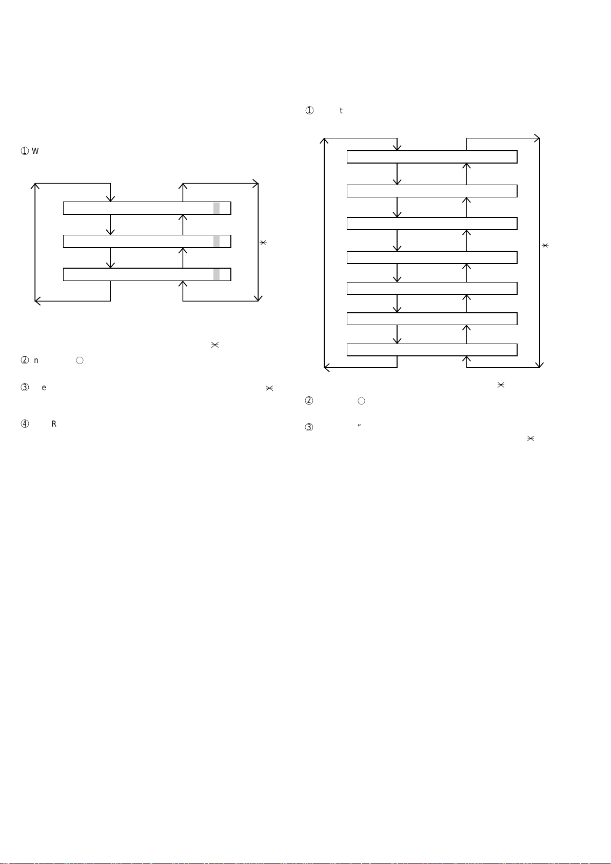
FO-4400U
FO-CS1
Rapid key 11: Life entry mode
(For Serviceman temporary counter)
The mode is used to set a desired value for the judgment value (alarm
judgment counter value) of the general purpose life counters 1 through
3 of the printer. If the life of a consumable part (developer , imprinter , etc)
is set, the model which has the error display and RMS function will inform RMS when the counter reaches the set value. For setting, proceed
with the following procedure.
1
When the life counter setting mode is selected, the following will be
displayed.
Rapid key 12: Life clear mode
The mode is used to respectively clear the life counter of the printer and
the counter of the auto feeder. For setting, proceed with the following
procedure.
1
When the life counter clearing mode is selected, the following will be
is displayed.
MACH I NE
LIFE
C
LEAR
# key
LI FE1= 0000
LI FE2= 0000
LI FE3= 0000
0
0
0
0
0
0
The cursor blinks at the top data.
Three counters can be selected with the "#" and " " keys.
2
In the state 1 , input a desired setting number of 6 digits with the
ten-key.
3
After input of 6 digits, shift to another counter with the "#" and " "
keys as necessary. When all necessary counters are completely input, press the START key.
4
"STORED" will be displayed with the set values stored into the
memory. For checking, retry this mode.
NOTE: The counter shows the operational state of the printer (how many
sheets have been printed since start of use?). The ordinary
memory does not reset the counter. Accordingly, it is necessary
to reset this counter in addition to the ordinary memory clear if
the content in the memory on the control PWB is broken because of PWB repair, etc. (In the production stage, it is necessary to execute this in the last process.)
key
DRUM
# key
FEEDER L I FE LEAR
TONER L I FE LEAR
LIFE
L
IFE1
LIFE2
LIFE3
LEAR
C
LEAR
C
LEAR
C
LEAR
C
C
C
key
Seven counters can be selected with the "#" and " " keys.
2
In the state 1, input the DEL key , and the counter will be respectively
cleared.
3
“CLEARED” is displayed and clearing is complete. After ending one
clear, move to another counter to clear with the “#” key, “ ” key, if
necessary. After clearing the necessary counter press down the
“STOP” key.
NOTE: The counter shows the operational state of the printer (how many
sheets have been printed since start of use?). The ordinary
memory does not reset the counter. Accordingly, it is necessary
to reset this counter in addition to the ordinary memory clear if
the content in the memory on the control PWB is broken because of PWB repair, etc. (In the production stage, it is necessary to execute this in the last process.)
2 – 8
Page 23
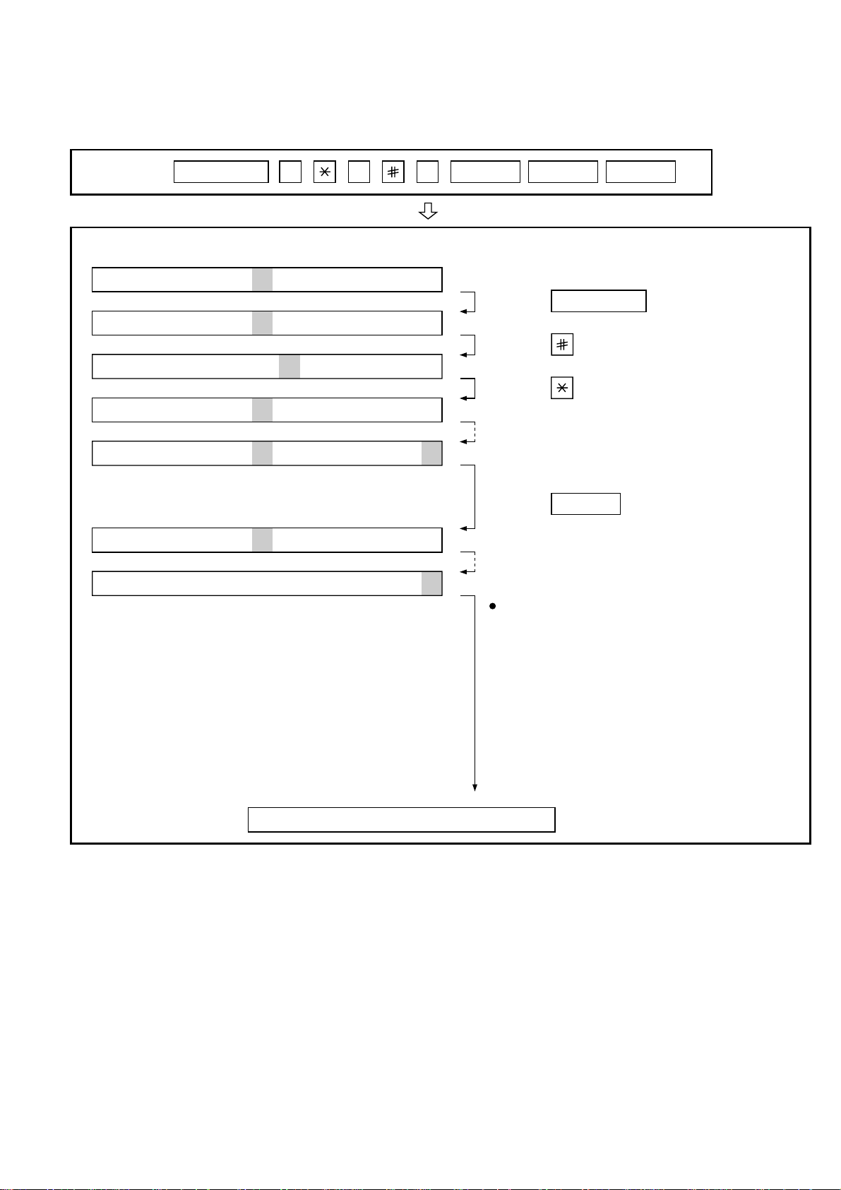
3. How to make soft switch setting
To enter the soft switch mode, make the following key entries in sequence.
FO-4400U
FO-CS1
Press
MENU
9 8 7 START ASTART
S F T S W 1 = 0 0 0 0 0 0 0 0
S F T S W 1 = 1 0 0 0 0 0 0 0
S F T S W 1 = 1 0 0 0 0 0 0 0
S F T S W 1 = 1 0 0 0 0 0 0 0
S F T S W 1 = 1 0 0 0 0 0 0 0
S F T S W 2 = 0 0 0 0 0 0 0 0
S F T S W 99 = 0 0 0 0 0 0 0 0
Press MENU key.
Press key.
Press key.
Bit1 - 8 are set.
Press key during setting.
START
Soft SW2 - 99 are set.
To finish the settings halfway between
SW1 and SW99, press the STOP key.
In this case, the setting being done to
the SW No. on display will be nullified
while settings done to the preceding
SW No. remain in effect.
The soft switch mode is terminated.
2 – 9
Page 24
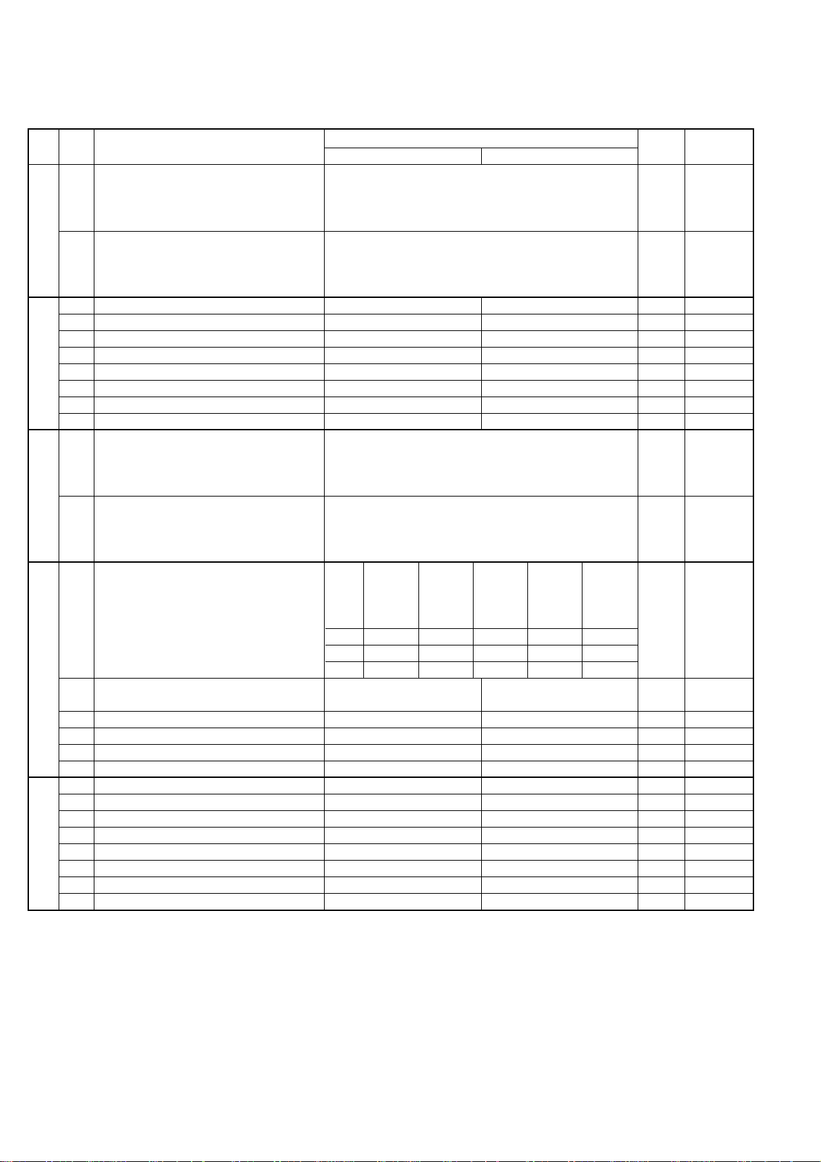
FO-4400U
FO-CS1
4. Soft switch description
• Soft switch
SW
DA TA
NO.
NO.
1 Recall interval Binary input 8 4 2 1 0 OPTION
2 No. = 1 2 3 4 (Data No.) 1 Set to 1~15
3 EX 0101 0
4 eg. Recall interval is set to 5 min. 1
SW1
5 Recall times Binary input 8 4 2 1 0 OPTION
6 No. = 5 6 7 8 (Data No.) 0 Set to 0~14
7 EX 0010 1
8 eg. Recall times is set to 2 times. 0
1 Dial mode PULSE TONE 0
2 Receive mode AUTO MANUAL 1
3 ECM mode Off On 0 OPTION
4 Reserved 0
SW2
5 Polling security On Off 1 OPTION
6 Auto cover sheet No Yes 1 OPTION
7 JUNK-FAX function in manual reception Yes No 0
8 JUNK-FAX function Yes No 0 OPTION
1 Number of rings for auto-receive Binary input 8 4 2 1 0 OPTION
2 (0: No ring receive) No. = 1 2 3 4 (Data No.) 0 Set to 0~9
3 EX 0001 0
4 eg. Number of rings for auto receive is set to 1 time. 1
SW3
5 Switch to auto-receive from manual receive Binary input 8 4 2 1 0 OPTION
6 (0: No switch) No. = 5 6 7 8 (Data No.) 0 Set to 0~9
7 EX 0000 0
8 eg. Switch to auto receive is set to disable. 0
Communication results printout Printed at Printed at Printed at
1 No. 1 0 0 0 1 1 0
2 No. 2 0 0 1 0 1 0
SW4 3 No. 3 1 0 0 0 0 1
4 Image addition function to the communication On Off 1 OPTION
result table (for memory transmission only)
5 Reserved 0
6 TEL billing code function On Off 0 OPTION
7 Billing code position Before After 1 OPTION
8 Multi-TTI feature On Off 0 OPTION
1 Time display format 24 hours 12 hours-AM/PM 0
2 Date display format Month-Day-Year Day-Month-Year 1
3 Header print Off On 0
4 Footer print On Off 0
SW5
5 Reserved 0
6 Substitute reception Off On 0
7 Substitute reception conditions Reception disable without TSI Reception enable without TSI 0
8 CSI transmission Off On 0
ITEM
error only
Switch setting and function
10
error/timer/
memory sion mode
only only
transmis- every time
Not printed
Printed OPTION
Initial
setting
Remarks
2 – 10
Page 25
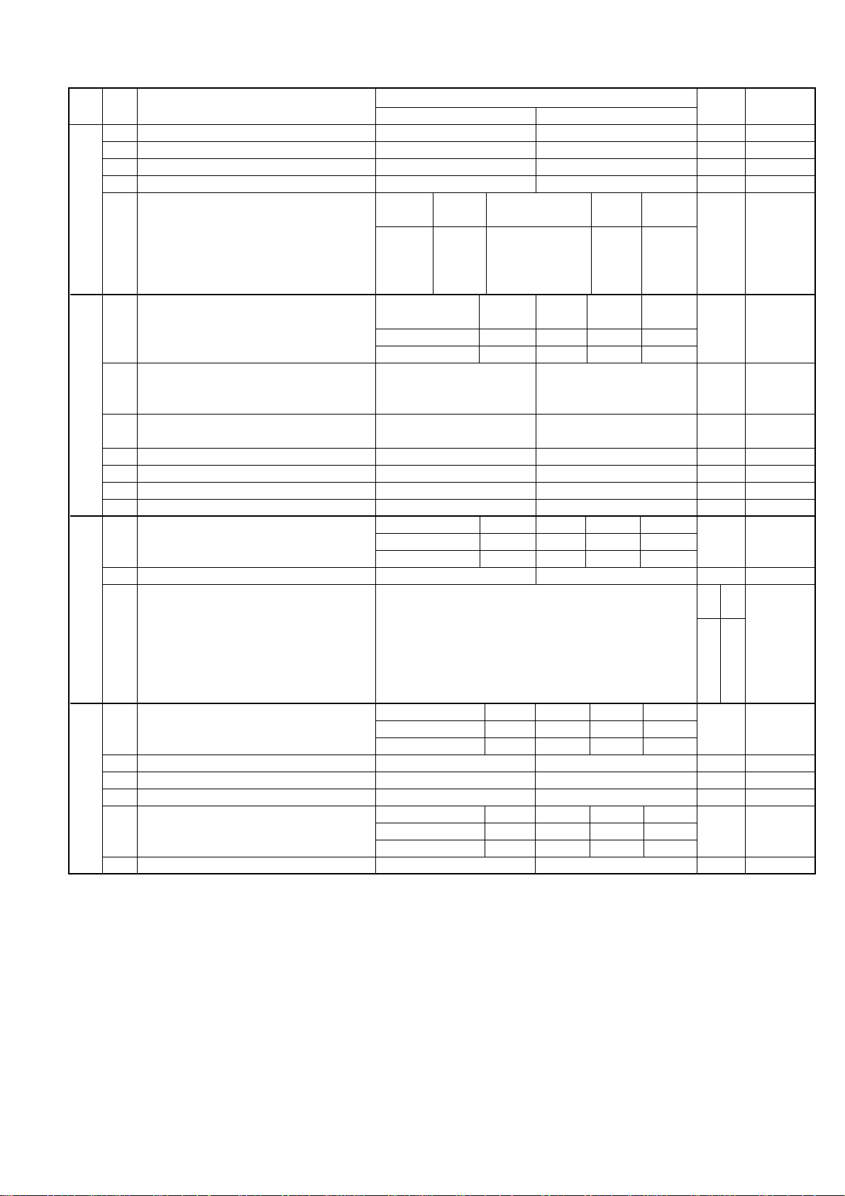
FO-4400U
FO-CS1
SW
DA TA
NO.
NO.
1 JBIG (Joint Bi-level Image Group) On Off 0
2 JBIG (Joint Bi-level Image Group) option On Off 0
3 MMR On Off 1
4MR On Off 1
SW6
SW7 comm.
SW8
SW9
Modem speed V.33 V.17 V. 29 V. 27ter
5 No. 5 0011110000 1
6 No. 6 1100000000 0
7 No. 7 0101010110 0
8 No. 8 0000111100 0
Reception speed fixed NO V. 17- V. 29- V. 27ter-
1 No. 1 0 1 0 1 0
2 No. 2 0 1 1 0 0
3 DIS receive acknowledge during Twice Once in NSF reception, twice 0 Effective to
G3 transmission in DIS reception international
4 Non-modulated carrier in V.29 On Off 0
transmission mode
5 CNG send when manual TX On Off 1
6 Protocol monitor On Off 0
7 Line monitor On Off 0
8 Reserved 0
Compromised equalizer 0Km 1.8Km 3.6Km 7.2Km Valid when
1 No. 1 0 0 1 1 0 transmitting
2 No. 2 0 1 0 1 0
3 H2 mode No Yes 0
Signal transmission level Binary input 16 8 4 2 1
4 EX 0 1 1 0 1 (For U.S.A.) 0 0
5 EX 0 1 0 0 0 (For Canada) 1 1
6 eg. Signal transmission level is set to -10dBm 1 0
7 00
8 10
CED tone signal interval 75ms 500ms 750ms 1000ms
1 No. 1 0 0 1 1 0
2 No. 2 0 1 0 1 0
3 Equalizer freeze On Off 0
4 Equalizer freeze conditions All 7200bps 0
5 CED detection time 500ms 1000ms 0
Alarm buzzer 3sec 1sec No BEEP No BEEP
6 No. 5 0 0 1 1 0
7 No. 6 0 1 0 1 0
8 Action when RTN received Handle to error Handle to no error 0
ITEM
Switch setting and function
10
14400 12000 14400 12000
No. = 4 5 6 7 8 (Data No.)
9600 7200 9600 7200 4800 2400
14400bps 9600bps 4800bps
Initial
setting
For For
U.S.A Canada
Remarks
When 14400
MODEM used,
setting to
14400
ignored.
bps
bps
is
2 – 11
Page 26
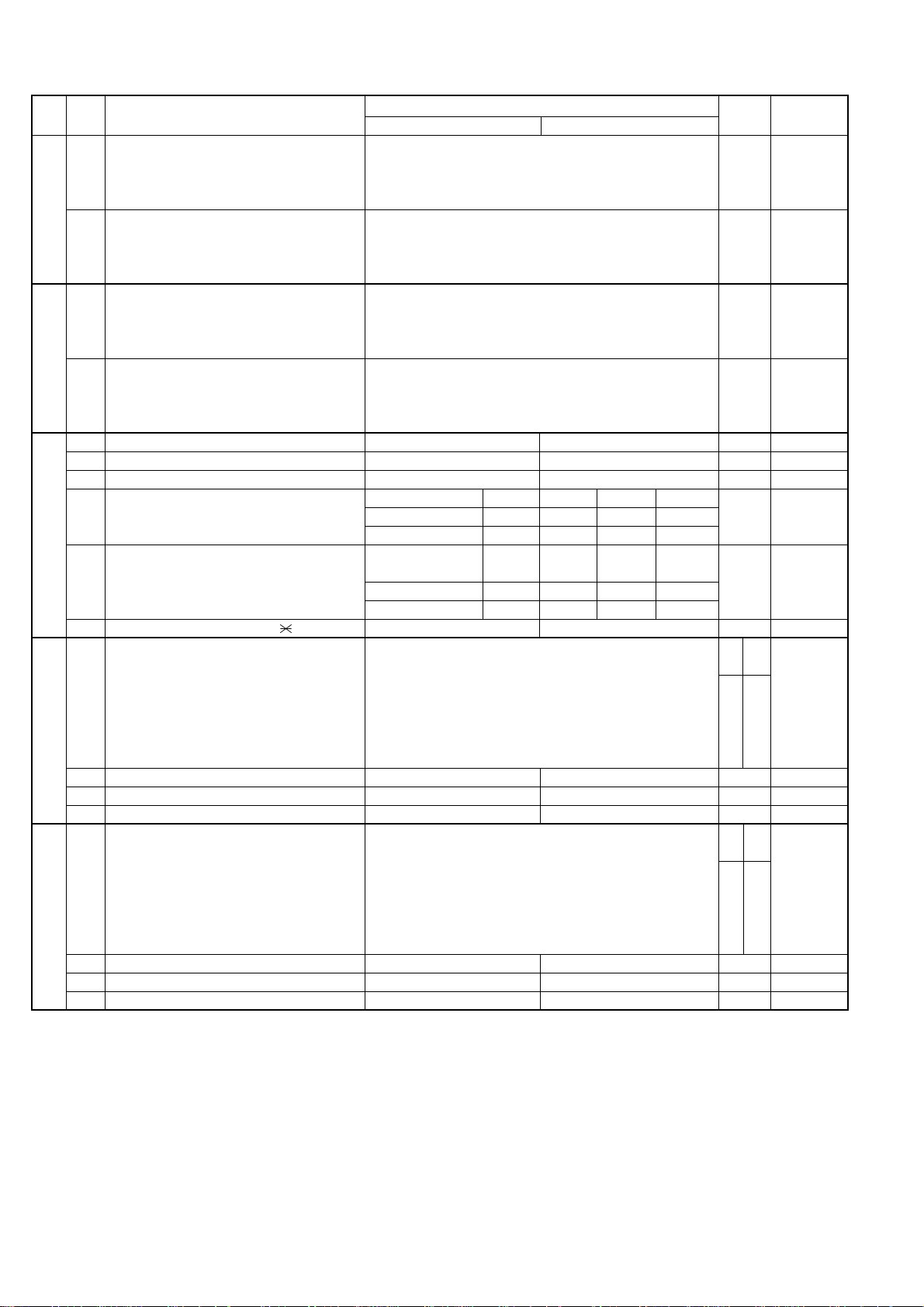
FO-4400U
FO-CS1
SW
NO.
SW10
SW11
SW12
SW13
SW14
DA TA
NO.
1 Memory retransmission times Binary input 8 4 2 1 1 OPTION
2 No. = 1 2 3 4 (Data No.) 0
3 EX 1010 1
4 eg. Retransmission time set to 10 times. 0
5 Memory retransmission interval Binary input 8 4 2 1 0 OPTION
6 No. = 5 6 7 8 (Data No.) 0
7 EX 0010 1
8 0
1 V.34 mode transmission speed Sending speed = 2400 (bps) x (N+1) 1
2 Example : 1
3 2400 (bps) x 12 = 28800 (bps) 1
4 2400 (bps) is set for N=0. 33600 (bps) is set for N=14. 0
5 V.34 mode receiving speed Receiving speed = 2400 (bps) x (N+1) 1
6 Example : 1
7 2400 (bps) x 12 = 28800 (bps) 1
8 2400 (bps) is set for N=0. 33600 (bps) is set for N=14. 0
1
V.34 mode function in case of manual communication
2 V.34 mode function On Off 1
3 V.34 control channel communication speed 2400bps 1200bps 0
EOL detection timer 13sec 25sec 5sec 5sec
4 No. 4 0 0 1 1 0
5 No. 5 0 1 0 1 0
Processing of DIS reception after DIS
transmission
6 No. 6 0 0 1 1 0
7 No. 7 0 1 0 1 0
8 The change to DB from DP by Yes No 0
DTMF output level (High) Binary input 16 8 4 2 1
1 EX 0 1 1 0 0 (For U.S.A.) 0 0
2 EX 0 1 0 0 0 (For Canada) 1 1
3 eg. Signal transmission level is set to -10dBm 1 0
4 00
5 00
6 Reserved 0
7 Reserved 0
8 Reserved 0
DTMF output level (Low) Binary input 16 8 4 2 1
1 EX 1 0 0 0 0 (For U.S.A.) 1 0
2 EX 0 1 1 0 0 (For Canada) 0 1
3 eg. Signal transmission level is set to -10dBm 0 1
4 00
5 00
6 Reserved 0
7 Reserved 0
8 Reserved 0
ITEM
On Off 1
Switch setting and function
10
Command
retransmitting
No. = 1 2 3 4 5 (Data No.) n x 0.5dBm
No. = 1 2 3 4 5 (Data No.) n x 0.5dBm
A line is Apply to T.30+α
cut T.30
Initial
setting
For For
U.S.A Canada
For For
U.S.A Canada
Remarks
2 – 12
Page 27
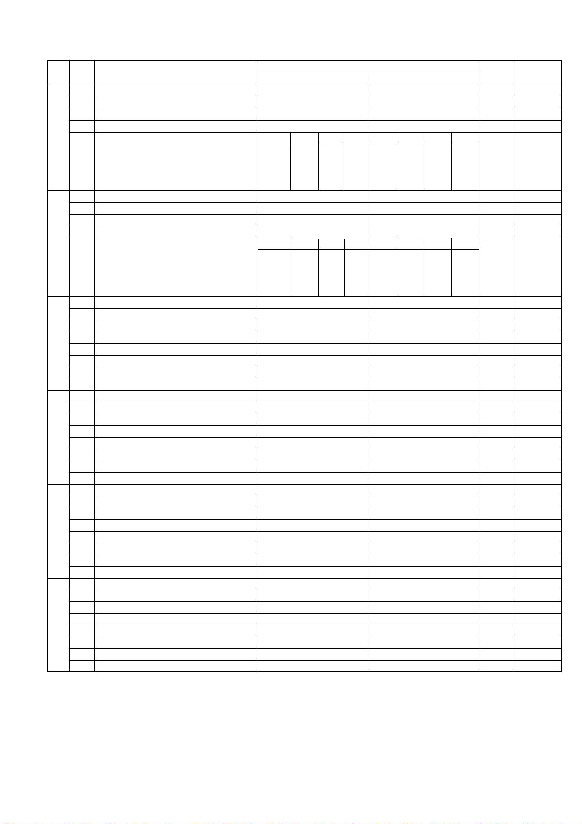
FO-4400U
FO-CS1
SW
NO.
SW15
SW16
SW17
SW18
SW19
SW20
DA TA
NO.
1 Reserved 0
2 Reserved 0
3 Reserved 0
4 Reserved 0
Cl Signal OFF detect enable time
5 No. 5 0 0 0 0 0 0 0 0
6 No. 6 0 0 0 0 1 1 1 1
7 No. 7 0 0 1 1 0 0 1 0
8 No. 8 0 1 0 1 0 1 0 1
1 Reserved 0
2 Reserved 0
3 Reserved 0
4 Reserved 0
Distinctive ringing OFF STD RING1RING2 RING3 RING4 RING5
5 No. 5 0 0 1 0 1 0 1 0
6 No. 6 0 0 0 1 1 0 0 0
7 No. 7 0 0 0 0 0 1 1 0
8 No. 8 0 1 0 0 0 0 0 0
1 Reserved 0
2 Reserved 0
3 Reserved 0
4 Reserved 0
5 Reserved 0
6 Reserved 0
7 Reserved 0
8 Reserved 1
1 Reserved 1
2 Reserved 0
3 Reserved 0
4 Reserved 0
5 Reserved 1
6 Reserved 1
7 Reserved 0
8 Reserved 0
1 Reserved 1
2 Reserved 0
3 Reserved 0
4 Reserved 0
5 Reserved 1
6 Reserved 0
7 Reserved 0
8 Reserved 0
1 Reserved 0
2 Reserved 0
3 Reserved 0
4 Reserved 0
5 Reserved 0
6 Reserved 0
7 Reserved 0
8 Reserved 0
ITEM
(ms)
Switch setting and function
10
200 300 350 400 500 700 1200
Initial
setting
Remarks
2 – 13
Page 28

FO-4400U
FO-CS1
SW
NO.
SW21
SW22
SW23
SW24
SW25
SW26
SW27
DA TA
NO.
1 Reserved 0
2 Reserved 0
3 Reserved 0
Busy tone detection frequency
4 No. 4 0 0 0 0 1 0
5 No. 5 0 0 1 1 0 0
6 No. 6 0 1 0 1 0 0
7 Reserved 0
8 Reserved 0
1 Reserved 0
2 Reserved 0
3 Reserved 0
4 Reserved 0
5 Reserved 0
6 Reserved 0
7 Reserved 0
8 Reserved 0
1 Reserved 0
2 Reserved 1
3 Reserved 0
4 Reserved 1
5 Reserved 0
6 Reserved 0
7 Reserved 1
8 Reserved 0
1 Reserved 0
2 Reserved 1
3 Reserved 0
4 Reserved 0
5 Reserved 1
6 Reserved 1
7 Reserved 0
8 Reserved 0
1 Reserved 0
2 Reserved 0
3 Reserved 0
4 Reserved 1
5 Reserved 0
6 Reserved 0
7 Reserved 0
8 Reserved 0
1 Reserved 0
2 Reserved 0
3 Reserved 1
4 Reserved 1
5 Reserved 0
6 Reserved 0
7 Reserved 1
8 Reserved 0
1 Reserved 0
2 Reserved 1
3 Reserved 0
4 Reserved 0
5 Reserved 0
6 Reserved 0
7 Reserved 0
8 Reserved 0
ITEM
Switch setting and function
10
520~640Hz 300~600Hz 380~500Hz
Reserve Reserve
Initial
setting
Remarks
2 – 14
Page 29

FO-4400U
FO-CS1
SW
NO.
SW28
SW29
SW30
SW31
SW32
SW33
DA TA
NO.
1 Reserved 0
2 Reserved 0
3 Reserved 1
4 Reserved 1
5 Reserved 1
6 Reserved 0
7 Reserved 0
8 Reserved 0
1 Reserved 0
2 Reserved 0
3 Reserved 0
4 Reserved 0
5 Reserved 1
6 Reserved 0
7 Reserved 0
8 Reserved 0
1 Reserved 0
2 Reserved 0
3 Reserved 0
4 Reserved 00
5 Reserved 11
6 Reserved 10
7 Reserved 00
8 Reserved 10
1 Reserved 0
2 Reserved 0
3 Reserved 0
4 Reserved 0
5 Reserved 0
6 Reserved 0
7 Reserved 0
8 Reserved 0
1 Reserved 1
2 Reserved 0
3 Reserved 1
4 Reserved 0
5 Reserved 0
6 Reserved 0
7 Reserved 1
8 Reserved 0
1 Reserved 1
2 Reserved 1
3 Reserved 1
4 Reserved 0
5 Reserved 1
6 Reserved 1
7 Reserved 1
8 Reserved 0
ITEM
Switch setting and function
10
Initial
setting
For For
U.S.A. Canada
Remarks
2 – 15
Page 30

FO-4400U
FO-CS1
SW
NO.
SW34
SW35
SW36
SW37
SW38
SW39
DATA
NO.
1 Reserved 1
2 Reserved 1
3 Reserved 0
4 Reserved 0
5 Reserved 0
6 Reserved 0
7 Reserved 0
8 Reserved 0
1 Reserved 00
2 Reserved 11
3 Reserved 10
4 Reserved 00
5 Reserved 00
6 Reserved 0
7 Reserved 0
8 Reserved 0
1 Reserved 10
2 Reserved 01
3 Reserved 01
4 Reserved 00
5 Reserved 00
6 Reserved 0
7 Reserved 0
8 Reserved 0
1 Reserved 0
2 Reserved 0
3 Reserved 0
4 Reserved 0
5 Reserved 0
6 Reserved 1
7 Reserved 0
8 Reserved 1
1 Reserved 0
2 Reserved 0
3 Reserved 0
4 Reserved 0
5 Reserved 0
6 Reserved 0
7 Reserved 0
8 Reserved 0
1 Reserved 0
2 Reserved 0
3 Reserved 0
4 Reserved 0
5 Reserved 0
6 Reserved 0
7 Reserved 0
8 Reserved 1
ITEM
Switch setting and function
10
Initial
setting
For For
U.S.A. Canada
For For
U.S.A. Canada
Remarks
2 – 16
Page 31

FO-4400U
FO-CS1
SW
NO.
SW40
SW41
SW42
SW43
SW44
SW45
DAT A
NO.
1 Reserved 1
2 Reserved 0
3 Reserved 0
4 Reserved 0
5 Reserved 1
6 Reserved 1
7 Reserved 0
8 Reserved 0
1 Reserved 1
2 Reserved 0
3 Reserved 0
4 Reserved 0
5 Reserved 1
6 Reserved 0
7 Reserved 0
8 Reserved 0
1 Reserved 0
2 Reserved 0
3 Reserved 0
4 Reserved 0
5 Reserved 0
6 Reserved 0
7 Reserved 0
8 Reserved 0
1 Reserved 0
2 Reserved 0
3 Reserved 0
4 Reserved 0
5 Reserved 0
6 Reserved 0
7 Reserved 0
8 Reserved 0
1 Reserved 0
2 Reserved 0
3 Reserved 0
4 Reserved 0
5 Reserved 0
6 Reserved 0
7 Reserved 0
8 Reserved 0
1 Reserved 0
2 Reserved 0
3 Reserved 0
4 Reserved 0
5 Reserved 0
6 Reserved 0
7 Reserved 0
8 Reserved 0
ITEM
Switch setting and function
10
Initial
setting
Remarks
2 – 17
Page 32

FO-4400U
FO-CS1
SW
NO.
SW46
SW47
SW48
SW49
SW50
SW51
DATA
NO.
1 Reserved 0
2 Reserved 0
3 Reserved 0
4 Reserved 0
5 Reserved 0
6 Reserved 0
7 Reserved 0
8 Reserved 0
1 Reserved 0
2 Reserved 0
3 Reserved 0
4 Reserved 0
5 Reserved 0
6 Reserved 0
7 Reserved 0
8 Reserved 0
1 Reserved 0
2 Reserved 0
3 Reserved 0
4 Reserved 0
5 Reserved 0
6 Reserved 0
7 Reserved 0
8 Reserved 0
1 Reserved 0
2 Reserved 0
3 Reserved 0
4 Reserved 0
5 Reserved 0
6 Reserved 0
7 Reserved 0
8 Reserved 0
1 Reserved 0
2 Reserved 0
3 Reserved 0
4 Reserved 0
5 Reserved 0
6 Reserved 0
7 Reserved 0
8 Reserved 0
1 Reserved 0
2 Reserved 0
3 Reserved 0
4 Reserved 0
5 Reserved 0
6 Reserved 0
7 Reserved 0
8 Reserved 0
ITEM
Switch setting and function
10
Initial
setting
Remarks
2 – 18
Page 33

FO-4400U
FO-CS1
SW
NO.
SW52
SW53
SW54
SW55
SW56
SW57
DA TA
NO.
1 Reserved 0
2 Reserved 0
3 Reserved 0
4 Reserved 0
5 Reserved 0
6 Reserved 0
7 Reserved 0
8 Reserved 0
1 Reserved 0
2 Reserved 0
3 Reserved 0
4 Reserved 0
5 Reserved 0
6 Reserved 0
7 Reserved 0
8 Reserved 0
1 Reserved 0
2 Reserved 0
3 Reserved 0
4 Reserved 0
5 Reserved 0
6 Reserved 0
7 Reserved 0
8 Reserved 0
1 Reserved 0
2 Reserved 0
3 Reserved 0
4 Reserved 0
5 Reserved 0
6 Reserved 0
7 Reserved 0
8 Reserved 0
1 Reserved 0
2 Reserved 0
3 Reserved 0
4 Reserved 0
5 Reserved 0
6 Reserved 0
7 Reserved 0
8 Reserved 0
1 Reserved 0
2 Reserved 0
3 Reserved 0
4 Reserved 0
5 Reserved 0
6 Reserved 0
7 Reserved 0
8 Reserved 0
ITEM
Switch setting and function
10
Initial
setting
Remarks
2 – 19
Page 34

FO-4400U
FO-CS1
SW
NO.
SW58
SW59
SW60
SW61
SW62
SW63
DA TA
NO.
1 Reserved 0
2 Reserved 0
3 Reserved 0
4 Reserved 0
5 Reserved 0
6 Reserved 0
7 Reserved 0
8 Reserved 0
1 Reserved 0
2 Reserved 0
3 Reserved 0
4 Reserved 0
5 Reserved 0
6 Reserved 0
7 Reserved 0
8 Reserved 0
1 Reserved 0
2 Reserved 0
3 Reserved 0
4 Reserved 0
5 Reserved 0
6 Reserved 0
7 Reserved 0
8 Reserved 0
1 F.A.S.T. (RMS) mode On Off 0
2 Reserved 0
3 Verification stamp Yes No 0
4 Day light saving No Yes 1
Key buzzer volume Off High Low Low
5 No. 5 0 0 1 1 1
6 No. 6 0 1 0 1 0
7 Reserved 0
8 Reserved 0
1 Speaker volume No. 1 0 0 1 1 1
2 No. 2 0 1 0 1 1
3 Reserved 1
4 Reserved 0
5 Ringer volume No. 5 0 0 1 1 1
6 No. 6 0 1 0 1 1
7 Reserved 0
8 Reserved 0
1 Reserved 0
2 Reserved 1
3 Reserved 0
4 Reserved 0
5 Reserved 1
6 Reserved 0
7 Reserved 1
8 Reserved 0
ITEM
Switch setting and function
10
High High Middle Low
Off High Middle Low
Initial
setting
Remarks
2 – 20
Page 35

FO-4400U
FO-CS1
SW
NO.
SW64
SW65
SW66
SW67
SW68
DA TA
NO.
1 Header registration On Off 0
2 Reserved 0
3 Continuous serial polling On Off 0
Time interval for continuous serial polling OPTION
4 No. 4 0 0 1 1 0
5 No. 5 0 1 0 1 0
6 Reserved 0
7 Reserved 0
8 Quick on line function Yes No 1
Cassette selection Manual Auto-1 Auto-2 Auto-1 OPTION
1 No. 1 0 0 1 1 0
2 No. 2 0 1 0 1 1
The 1st priority cassette None Tray
3 No. 3 0 0 0 0 Other 0
4 No. 4 0 0 1 1
5 No. 5 0 1 0 1 0
The 2nd priority cassette None Tray
6 No. 6 0 0 0 0 Other 0
7 No. 7 0 0 1 1
8 No. 8 0 1 0 1 1
The 3rd priority cassette None Tray
1 No. 1 0 0 0 0 Other 0
2 No. 2 0 0 1 1
3 No. 3 0 1 0 1 1
Cassette selection of separate page None Tray
4 No. 4 0 0 1 1 0
5 No. 5 0 1 0 1 1
6 Reserved 0
7 Reserved 0
8 Reserved 0
Power save mode OFF ON OPTION
1 No.1 0 0 0
2 No.2 0 1 0
Density adjustment of print bias Binary input 4 2 1 set to 1~7.
3 No. = 3 4 5 (Data No.) 1: faint 6: deep 1 set to 0, is
4 EX 1 0 0 0 equal to 4
5 eg. Bias is set to level 4. 0 (100)
Drum life detection
6 No. 6 0 0 1 1 1
7 No. 7 0 1 0 1 1
8 Reserved 0
Distinctive ring pattern U.S.A. Canada Australia Hong Kong
1 No. 1 0 0 1 1 0 0
2 No. 2 0 1 0 1 0 1
3 Reserved 0
4 Reserved 1
5 Reserved 0
6 Reserved 0
7 Reserved 1
8 Reserved 0
ITEM
Switch setting and function
10
0 min. 30 min. 60 min. 120 min.
No Detection
1st Cass. 2nd Cass.
1st Cass. 2nd Cass.
1st Cass. 2nd Cass.
Over only
1st Cass. 2nd Cass.
Near and Over Near and Over
Tray OPTION
Combination
Tray OPTION
Combination
Tray OPTION
Combination
Initial
setting
When SW64 -No.3
is on, option setting
It is effective
only when
1
No.31-1/2 are
set up of manual
It is effective
only when
1
No.31-1/2 are
set up of manual
It is effective
only when
0
No.31-1/2 are
set up of manual
For For
U.S.A. Canada
Remarks
can be set up
OPTION
2 – 21
Page 36

FO-4400U
FO-CS1
SW
NO.
SW69
SW70
SW71
SW72
SW73
SW74
DA TA
NO.
1 Reserved 1
2 Reserved 0
3 Reserved 0
4 Reserved 1
5 Reserved 0
6 Reserved 1
7 Reserved 1
8 Reserved 0
1 Reserved 1
2 Reserved 0
3 Reserved 1
4 Reserved 0
5 Reserved 0
6 Reserved 0
7 Reserved 0
8 Reserved 1
The default resolution for copying Standard Fine S-Fine U-Fine OPTION
1 No. 1 0 0 1 1 0
2 No. 2 0 1 0 1 1
Reserved 0
3
4 Reserved 1
5 Reserved 0
Picture quality priority mode Standard Fine S-Fine U-Fine OPTION
6 No. 6 0 0 1 1 0
7 No. 7 0 1 0 1 0
8 Reserved 0
1 Reserved 1
2 Reserved 0
3 Reserved 1
4 Reserved 0
5 Reserved 0
6 Reserved 0
7 Reserved 0
8 Reserved 0
1 Reserved 0
2 Reserved 0
3 Reserved 0
4 Reserved 0
5 Reserved 0
Data reduction AUTO 100%
6 (Except notation: Setting prohibition) No. 6 0 1 Set up to 100% except the 0
7 No. 7 0 0 notation 0
8 No. 8 0 0 0
1 Automatic printing of activity report Yes (When memory full)
2
Print out of total time and total number of pages on activity report
3 Reserved 0
4 Department function On Off 0
5 Department ID digit Binary input 8 4 2 1 0 OPTION
6 No. = 5 6 7 8 (Data No.) 1 set to 3~9
7 EX 0100 0
8 eg. Department ID is set to 4 digits 0
ITEM
Off On 0
Switch setting and function
10
No (First data is cleared when memory full)
Initial
setting
Remarks
The number in ( ) is
applicable for the
footer print on. Auto
is equivalent to 100%.
0 OPTION
2 – 22
Page 37

FO-4400U
FO-CS1
SW
NO.
SW75
SW76
SW77
SW78
SW79
SW80
DA TA
NO.
1 Copy protect switch On Off 0
2 Cut-off mode (when copy mode) Continue Cut-off 0 OPTION
3 Scanning ratio in memory input 1 : 1 Reduce 0
4
Overseas communication mode selection function
5 Reserved 0
Reduce ratio when copy mode AUTO 100%
6 (Except notation: Setting prohibition) No. 6 0 1 Set up to 100% except the 1
7 No. 7 0 0 notation 0
8 No. 8 0 0 0
1 Reserved 0
2 Reserved 0
Density adjustment (when Fine/STD mode) Normal Faint Deep
3 No. 3 0 0 1 1 0
4 No. 4 0 1 0 1 0
Density adjustment (when Half-tone mode) Normal Faint Deep
5 No. 5 0 0 1 1 0
6 No. 6 0 1 0 1 0
7 MTF correction in half-tone mode On Off 1
8 MTF intensity in half-tone mode Strong Weak 0
1 Cassette define LTR/A4: Tray A4 LTR 0
2 Cassette define LTR/A4: Upper A4 LTR 0
3 Cassette define LTR/A4: Lower A4 LTR 0
4 Reserved 1
5 Reserved 1
6 Reserved 0
7 Reserved 0
8 Reserved 0
1 Reserved 1
2 Reserved 0
3 Reserved 0
4 Reserved 0
5 Reserved 0
6 Reserved 0
7 Reserved 0
8 Reserved 0
1 Secure billing code Yes No 0
2 Pause with SHIFT key Yes No 0
3 Reserved 0
4 Z key pause time Binary input 16 8 4 2 1 0
5 (250ms unit) No. = 4 5 6 7 8 (Data No.) 0
6 EX 00000 0
7 eg. Pause time 250ms 0
8 Time=(n+1) x 250ms 0
1 Separate feature On Off 0
2 Reserved 0
3 Reserved 0
4 Reserved 0
5 Addition of header (Sender information) On Off 1
6 DTMF sending by the panel test On Off 0
7 Power save mode Real time Timer 1
8 Reserved 0
ITEM
Yes No 0
Switch setting and function
10
Deep (when Dark mode)
Deep (when Dark mode)
Initial
setting
Remarks
Memory scanning
When W cassette
Ignore when W cassette
Only when special
billing code is given.
Only when the
special billing code
is given. The
ordinary pause is
not affected.
2 – 23
Page 38

FO-4400U
FO-CS1
SW
NO.
SW81
SW82
SW83
SW84
SW85
SW86
DATA
NO.
1 Reserved 1
2 Reserved 0
3 Reserved 1
4 Reserved 1
5 Reserved 1
6 Reserved 1
7 Reserved 1
8 Reserved 1
1 Reserved 0
2 Reserved 1
3 Reserved 0
4 Reserved 1
5 Reserved 0
6 Reserved 0
7 Reserved 0
8 Reserved 0
1 Reserved 0
2 Reserved 0
3 Reserved 0
4 Reserved 0
5 Reserved 0
6 Reserved 1
7 Reserved 0
8 Reserved 1
1 Reserved 0
2 Reserved 0
3 Reserved 0
4 Reserved 0
5 Reserved 0
6 Reserved 0
7 Reserved 0
8 Reserved 0
1 Reserved 0
2 Reserved 0
3 Reserved 0
4 Reserved 0
5 Reserved 1
6 Reserved 0
7 Reserved 1
8 Reserved 0
1 Reserved 0
2 Reserved 0
3 Reserved 0
4 Reserved 0
5 Reserved 0
6 Reserved 0
7 Reserved 0
8 Reserved 0
ITEM
Switch setting and function
10
Initial
setting
Remarks
2 – 24
Page 39

FO-4400U
FO-CS1
SW
NO.
SW87
SW88
SW89
SW90
SW91
SW92
SW93
DAT A
NO.
1 Reserved 0
2 Reserved 0
3 Reserved 0
4 Reserved 0
5 Reserved 0
6 Reserved 0
7 Reserved 0
8 Reserved 0
1 Reserved 0
2 Reserved 0
3 Reserved 0
4 Reserved 0
5 Reserved 0
6 Reserved 0
7 Reserved 0
8 Reserved 0
1 Reserved 0
2 Reserved 0
3 Reserved 0
4 Reserved 0
5 Reserved 0
6 Reserved 0
7 Reserved 0
8 Reserved 1
1 Reserved 0
2 Reserved 0
3 Reserved 1
4 Reserved 0
5 Reserved 0
6 Reserved 1
7 Reserved 0
8 Reserved 1
1 Reserved 0
2 Reserved 0
3 Reserved 0
4 Reserved 0
5 Reserved 0
6 Reserved 0
7 Reserved 0
8 Reserved 0
1 Reserved 0
2 Reserved 1
3 Waiting time after dialing 90sec
4 Show receiver’s name Yes (Show) No (Hide) 1
5 Reserved 0
6 Reserved 0
7 Reserved 0
8 Reserved 0
1 Reserved 0
2 Reserved 0
3 Reserved 0
4 Reserved 0
5 Reserved 0
6 Reserved 0
7 Reserved 0
8 Reserved 0
ITEM
Switch setting and function
10
The specification of each country is followed
Initial
setting
0
Remarks
2 – 25
Page 40

FO-4400U
FO-CS1
SW
NO.
SW94
SW95
SW96
SW97
SW98
SW99
DATA
NO.
1 Reserved 0
2 Reserved 0
3 Reserved 0
4 Reserved 0
5 Reserved 0
6 Reserved 0
7 Reserved 0
8 Reserved 0
1 Reserved 0
2 Reserved 0
3 Reserved 0
4 Reserved 0
5 Reserved 1
6 Reserved 1
7 Reserved 0
8 Reserved 1
1 Reserved 0
2 Reserved 0
3 Reserved 0
4 Reserved 0
5 Reserved 0
6 Reserved 0
7 Reserved 0
8 Reserved 0
1 Reserved 0
2 Reserved 0
3 Reserved 0
4 Reserved 0
5 Reserved 0
6 Reserved 0
7 Reserved 0
8 Reserved 0
1 Reserved 0
2 Reserved 0
3 Reserved 0
4 Reserved 0
5 Reserved 0
6 Reserved 0
7 Reserved 0
8 Reserved 0
1 Reserved 0
2 Reserved 10
3 Reserved 10
4 Reserved 0
5 Reserved 0
6 Reserved 0
7 Reserved 1
8 Reserved 1
ITEM
Switch setting and function
10
Initial
setting
For For
U.S.A. Canada
For For
U.S.A. Canada
Remarks
2 – 26
Page 41

• Soft switch function description
SW1 No. 1 ~ No. 4 Recall interval
Choice is made for a recall interval for speed and rapid dial numbers.
Use a binary number to program this. If set to 0 accidentally, 1 will be
assumed.
SW1 No. 5 ~ No. 8 Recall times
Choice is made as to how many recall times should be made. Use a
binary number to program this.
SW2 No. 1 Dial mode
Switch the type according to the telephone circuit connected to the facsimile.
0: PULSE DIAL
1: TONE DIAL
SW2 No. 2 Receive mode
Auto/manual receiving mode is set.
SW2 No. 3 ECM mode
Used to determine ECM mode function.
SW2 No. 4 Reserved
Set to "0".
SW2 No. 5 Polling security
This switch is employed to enable or disable the polling operation using
the ID code verification function, in order to prevent unauthorized polling
operation.
SW2 No. 6 Auto cover sheet
When "1" (=YES) is selected, the cover sheet is automatically sent after
transmission of the original to notify the receiver of the number of original sheets transmitted.
SW2 No. 7 JUNK-FAX function in manual reception
It is set whether JUNK-FAX is functioned in the manual receiving mode
or not.
SW2 No. 8 JUNK-FAX function
This function is used to receive data from a specific remote machine
(station registered in entry mode). It is the function that refused a reception in the case that TSI of remote machine matched with fax number of
the station registered.
0: No
1: Yes
SW3 No. 1 ~ No. 4 Number of rings for auto-receive
(0: No ring receive)
When the machine is set in the auto receive mode, the number of rings
before answering can be selected. It may be set from one to nine rings
using a binary number. If the soft switch was set to 1, a direct connection
is made to the facsimile. If it was set to 0 accidentally, receive ring is set
to 1. If it was above 9, receive rings are set to 9.
SW3 No. 5 ~ No. 8 Switch to auto-receive from manual receive
(0: No switch)
This setting allows machine to switch from manual to Auto Receive mode.
Setting this number to 0 forces machine to stay in Manual receive mode.
Entering the binary number 0 forces the machine to remain in the manual
answer mode. If a number between 1 and 9 is entered, the machine will
go into the answer mode after the given number of rings. However, it can
be used as an ordinary telephone if the handset is taken off the hook
before this programmed number is finished. If entry of a number above 9
by accident, it will be set to 9. In this case, it must be corrected to the
proper number.
FO-4400U
FO-CS1
SW4 No. 1 ~ No. 3 Communication results printout
It is possible to obtain communication results after each transaction.
Normally, the switch is set (No. 1: 0, No. 2: 0, No. 3: 1) so that the
communication result is produced only a communication error is encountered. If No. 1 was set to 1, No. 2 was set to 1 and No. 3 was set to
0, the communication result will be produced every time a communication is done, even if the communication was successful.
If No. 1 was set to 0, No. 2 to 1 and No. 3 to 0, the communication result
will be produced every transmission.
Setting No. 1 to 1 No. 2 to 0 and No. 3 to 0 will disable this function. No
transaction report will be printed.
If No. 1 was set to 0, No. 2 to 0 and No. 3 to 0, the communication result
is produced only after a timer and memory transmission or when a communication error is encountered.
SW4 No. 4 Image addition function to the communication result
table (for memory transmission only)
Used to set addition of sending image to the communication result table.
SW4 No. 5 Reserved
Set to "0".
SW4 No. 6 TEL billing code function
When set to "1", the TEL billing code function is enabled.
SW4 No. 7 Billing code position
When set to "1", the billing code is delivered before dialing the remote
number. When set to "0", the billing code is delivered after dialing.
SW4 No. 8 Multi-TTI feature
When this switch is set to "1", Multi TTI function is enabled.
SW5 No. 1 Time display format
When this switch is set to "0", time is displayed in 12-hour system.
When set to "1", 24-hour system.
SW5 No. 2 Date display format
Used to select date display/print formats.
0: DAY-Month-Y ear
1: Month-DAY-Y ear
SW5 No. 3 Header print
When it is set at 0, sender’s name, sending page number and so on are
automatically printed in the recording paper on the receiving side during
transmission. Thus, the sender can be known on the receiving side.
0: Applied.
1: Not applied.
SW5 No. 4 Footer print
When set to "1", the date of reception, the sender machine No., and the
page No. are automatically recorded at the end of reception.
SW5 No. 5 Reserved
Set to "0".
SW5 No. 6 Substitute reception
Selection of substitute reception in the case of recording paper ex-hausted
or paper jam. If set to "NO", auto receive is disabled even when the
receive memory is ready to receive.
Substitute reception is not performed even during receive operation.
SW5 No. 7 Substitute reception conditions
Selection of substitute reception according to existence of TEL number
from transmitting side. Initial setting allows substitute reception without
CSI. If set to "no", the receiver cannot receive any documents
SW5 No. 8 CSI transmission
CSI signal contains the sender’s phone number registered in the machine. If this switch is set to "1", no sender’s name will be printed at the
receiving side.
SW6 No. 1 JBIG (Joint Bi-level Image Group)
An image compression encoding method recommended by ITU-T . It realizes 2-second transmission when the power is turned on.
SW6 No. 2 JBIG (Joint Bi-level Image Group) option
An optional function for JBIG.
SW6 No. 3 MMR
MMR (Modified MR) selects presence of the compression function.
2 – 27
Page 42

FO-4400U
FO-CS1
SW6 No. 4 MR
MR (Modified READ) selects presence of the compression function.
SW6 No. 5 ~ No. 8 Modem speed
Used to determine the initial modem speed. The default is
14400BPS(V.17). It may be necessary to program it to a slower speed
when frequent line fallback is encountered, in order to save the time
required for the fallback procedure.
SW7 No. 1, No. 2 Reception speed fixed
The transferable speed of modem in the receiving mode is set.
SW7 No. 3 DIS receive acknowledge during G3 transmission
Used to make a choice of whether reception of NSF (DIS) is acknowledged after receiving two NSFs (DISs) or receiving one NSF (two DISs).
It may be useful for overseas communication to avoid an echo suppression problem, if set to 1.
SW7 No. 4 Non-modulated carrier in V.29 transmission mode
Though transmission of a non-modulated carrier is not required for transmission by the V29 modem according to the CCITT Recommendation, it
may be permitted to send a non-modulated carrier before the image
signal to avoid an echo suppression problem. It may be useful for overseas communication to avoid an echo suppression problem, if set to 1.
SW7 No. 5 CNG send when manual TX
CNG signal sending ON/OFF in case of manual transmission is set.
SW7 No. 6 Protocol monitor
Normally set to "0". If set to "1", communication can be checked, in case
of troubles, without using a G3 tester or other tools.
When communication FSK data transmission or reception is made, the
data is taken into buffer. When communication is finished, the data
analyzed and printed out. When data is received with the line monitor
(SW7-No. 7) set to "1" the reception level is also printed out.
SW7 No. 7 Line monitor
Normally set to "0". If set to "1", the transmission speed and the reception level are displayed on the LCD. Used for line tests.
SW7 No. 8 Reserved
Set to "0".
SW8 No. 1, No. 2 Compromised equalizer
The specific line equalizer is inserted.
No. 1 No. 2
0 0 The line equalizer built in the modem is turned off.
0 1 Line equalizer corresponding to 1.8 km
1 0 Line equalizer corresponding to 3.6 km
0 1 Line equalizer corresponding to 7.2 km
SW8 No. 3 H2 mode
Used to determine H2 mode (15sec transmission mode). When set to
OFF, H2 mode is inhibited even though the transmitting machine has
H2 mode.
SW8 No. 4 ~ No. 8 Signal transmission level
Used to control the signal transmission level in the range of –0dB to
–31dB.
SW9 No. 1, No. 2 CED tone signal interval
For international communication, the 2100Hz CED tone may act as an
echo suppresser switch, causing a communication problem. Though this
soft switch is normally set to "0", it should be set to "1" so as to change
the time between CED tone and DIS signal from 75ms to 500ms to
eliminate the communication problem caused by echo.
SW9 No. 3 Equalizer freeze
This switch is used to perform reception operation by fixing the equalizer control of modem for the line which is always in an unfavorable
state and picture cannot be received. Usually, the control is executed
according to the state of line where the equalizer setting is changed
always.
SW9 No. 4 Equalizer freeze conditions
Setting which specifies SW9 No.3 control only in condition of 7200bps
modem speed.
SW9 No. 5 CED detection time
The detection time of the CED signal from the called side in the auto
calling mode is set.
SW9 No. 6, No. 7 Alarm buzzer
The length of the buzzer for normal end of operation is set.
SW9 No. 8 Action when RTN received
The operation is set when the RTN signal is received in the G3 transmission mode.
SW10 No. 1 ~ No. 4 Memory retransmission times
The number of memory retransmissions is set.
SW10 No. 5 ~ No. 8 Memory retransmission interval
The interval between memory retransmissions is set.
SW11 No. 1 ~ No. 4 V.34 mode transmission speed
Used to determine the initial modem speed when communication method
is V.34 transmission mode.
SW11 No. 5 ~ No. 8 V.34 mode receiving speed
Used to determine the initial modem speed when communication method
is V.34 reception mode.
SW12 No. 1 V.34 mode function in case of manual communication
Used to select whether the V .34 mode is made valid when automatically
transmitting/receiving.
SW12 No. 2 V.34 mode function
Used to select the V.34 mode for communication when set to “1”, communication method is V.34 mode..
SW12 No. 3 V.34 control channel communication speed
Used to select the control channel communication speed for V .34 mode.
SW12 No. 4, No. 5 EOL detection timer
Used to make a choice of whether to use the 25-second or 13-second
timer for detection of End of line This is effective to override communication failures with some facsimile models that have longer End of line
detection.
SW12 No. 6, No. 7 Processing of DIS reception after DIS transmission
When receiving , operation in case of DIS reception after DIS transmission is selected. Retransmitting command: To retransmit DIS in disregard of DIS reception.
Breaking circuit: To break circuit instantly. (Abnormal finish)
T. 30: To operate in accordance with T.30.
T. 30+α: To operate in accordance with T.30+α. (To operate differently
according to cases.)
SW12 No. 8 The change to DB from DP by
When setting to 1, the mode is changed by pressing the key from the
pulse dial mode to the tone dial mode.
SW13 No. 1 ~ No. 5 DTMF output level (High)
To set the level to output high group DTMF signals. –15 to 0 dBm (0.5
dBm unit)
SW13 No. 6 ~ No. 8 Reserved
Set to "0".
SW14 No. 1 ~ No. 5 DTMF output level (Low)
To set the level to output low group DTMF signals. –15 to 0 dBm (0.5
dBm unit)
SW14 No. 6 ~ No. 8 Reserved
Set to "0".
SW15 No. 1 ~ No. 4 Reserved
Set to "0".
SW15 No. 5 ~ No. 8 Cl signal OFF detect enable time
Used to set the continuous detection time during OFF period of Cl signal.
SW16 No. 1 ~ No. 4 Reserved
Set to "0".
2 – 28
Page 43

SW16 No. 5 ~ No. 8 Distinctive ringing
When the ringing setting is turned off, all of the CI signal are received.
When any of the standard, and ring patterns 1 through 3 is selected for
the ringing setting, only the selected CI signal is received.
CI signal patterns
The CI signal patterns consists of the standard pattern, and ring patterns 1 through 7. The standard pattern is the conventional one.
2S
4S
2S
2S
1.5S
STANDARD
RING
PATTERN 1
for USA
RING
PATTERN 2
for USA
RING
PATTERN 3
for USA
RING
PATTERN 4
for USA
RING
PATTERN 1
for CANADA
RING
PATTERN 2
for CANADA
RING
PATTERN 3
for CANADA
1S
0.8S
0.3S
0.2S
0.4S
0.2S 0.2S
1S
1S
0.5S
0.5S
1.5S
0.5S
0.8S
0.4S
1S
0.3S
0.2S
0.4S 0.8S
1S
0.5S
1S 0.5S
0.5S
0.5S0.5S
0.5S
1S
3S
4S
4S
4S
4S
4S
1S
3S
3.5S
0.5S0.5S
1S
3S
3S
SW17 No. 1 ~ No. 7 Reserved
Set to "0".
SW17 No. 8 Reserved
Set to "1".
SW18 No. 1 Reserved
Set to "1".
SW18 No. 2 ~ No. 4 Reserved
Set to "0".
SW18 No. 5 , No. 6 Reserved
Set to "1".
SW18 No. 7 , No. 8 Reserved
Set to "0".
SW19 No. 1 Reserved
Set to "1".
SW19 No. 2 ~ No. 4 Reserved
Set to "0".
SW19 No. 5 Reserved
Set to "1".
SW19 No. 6 ~ No. 8 Reserved
Set to "0".
SW20 No. 1 ~ No. 8 Reserved
Set to "0".
SW21 No. 1 ~ No. 3 Reserved
Set to "0".
SW21 No. 4 ~ No. 6 Busy tone detection frequency
To select frequency range of signals to be detected as Busy Tone.
FO-4400U
FO-CS1
SW21 No. 7, No. 8 Reserved
Set to "0".
SW22 No. 1 ~ No. 8 Reserved
Set to "0".
SW23 No. 1 Reserved
Set to "0".
SW23 No. 2 Reserved
Set to "1".
SW23 No. 3 Reserved
Set to "0".
SW23 No. 4 Reserved
Set to "1".
SW23 No. 5, No. 6 Reserved
Set to "0".
SW23 No. 7 Reserved
Set to "1".
SW23 No. 8 Reserved
Set to "0".
SW24 No. 1 Reserved
Set to "0".
SW24 No. 2 Reserved
Set to "1".
SW24 No. 3, No. 4 Reserved
Set to "0".
SW24 No. 5, No. 6 Reserved
Set to "1".
SW24 No. 7, No. 8 Reserved
Set to "0".
SW25 No. 1 ~ No. 3 Reserved
Set to "0".
SW25 No. 4 Reserved
Set to "1".
SW25 No. 5 ~ No. 8 Reserved
Set to "0".
SW26 No. 1, No. 2 Reserved
Set to "0".
SW26 No. 3, No. 4 Reserved
Set to "1".
SW26 No. 5, No. 6 Reserved
Set to "0".
SW26 No. 7 Reserved
Set to "1".
SW26 No. 8 Reserved
Set to "0".
SW27 No. 1 Reserved
Set to "0".
SW27 No. 2 Reserved
Set to "1".
SW27 No. 3 ~ No. 8 Reserved
Set to "0".
SW28 No. 1, No. 2 Reserved
Set to "0".
SW28 No. 3 ~ No. 5 Reserved
Set to "1".
SW28 No. 6 ~ No. 8 Reserved
Set to "0".
SW29 No. 1 ~ No. 4 Reserved
Set to "0".
SW29 No. 5 Reserved
Set to "1".
SW29 No. 6 ~ No. 8 Reserved
Set to "0".
2 – 29
Page 44

FO-4400U
FO-CS1
SW30 No. 1 ~ No. 4 Reserved
Set to "0".
SW30 No. 5 Reserved (For U.S.A.)
Set to "1".
SW30 No. 6 Reserved (For U.S.A.)
Set to "1".
SW30 No. 6 Reserved (For Canada)
Set to "0".
SW30 No. 7 Reserved
Set to "0".
SW30 No. 8 Reserved (For U.S.A.)
Set to "1".
SW30 No. 8 Reserved (For Canada)
Set to "0".
SW31 No. 1 ~ No. 8 Reserved
Set to "0".
SW32 No. 1 Reserved
Set to "1".
SW32 No. 2 Reserved
Set to "0".
SW32 No. 3 Reserved
Set to "1".
SW32 No. 4 ~ No. 6 Reserved
Set to "0".
SW32 No. 7 Reserved
Set to "1".
SW32 No. 8 Reserved
Set to "0".
SW33 No. 1 ~ No. 3 Reserved
Set to "1".
SW33 No. 4 Reserved
Set to "0".
SW33 No. 5 ~ No. 7 Reserved
Set to "1".
SW33 No. 8 Reserved
Set to "0".
SW34 No. 1, No. 2 Reserved
Set to "1".
SW34 No. 3 ~ No. 8 Reserved
Set to "0".
SW35 No. 1 Reserved
Set to "0".
SW35 No. 2 Reserved
Set to "1".
SW35 No. 3 Reserved (For U.S.A.)
Set to "1".
SW35 No. 3 Reserved (For Canada)
Set to "0".
SW35 No. 4 ~ No. 8 Reserved
Set to "0".
SW36 No. 1 Reserved (For U.S.A.)
Set to "1".
SW36 No. 1 Reserved (For Canada)
Set to "0".
SW36 No. 2 Reserved (For U.S.A.)
Set to "0".
SW36 No. 2 Reserved (For Canada)
Set to "1".
SW36 No. 3 Reserved (For U.S.A.)
Set to "0".
SW36 No. 3 Reserved (For Canada)
Set to "1".
SW36 No. 4 ~ No. 8 Reserved
Set to "0".
SW37 No. 1 ~ No. 5 Reserved
Set to "0".
SW37 No. 6 Reserved
Set to "1".
SW37 No. 7 Reserved
Set to "0".
SW37 No. 8 Reserved
Set to "1".
SW37 No. 5 ~ No. 8 CI signal off detect enable time
Used to set the continuous detection time during OFF period of CI signal. Normally set to 700ms, where the short ring (500ms: OFF period)
cannot be detected. Therefore, selection of 350ms is allowed.
SW38 No. 1 ~ No. 8 Reserved
Set to "0".
SW39 No. 1 ~ No. 7 Reserved
Set to "0".
SW39 No. 8 Reserved
Set to "1".
SW40 No. 1 Reserved
Set to "1".
SW40 No. 2 ~ No. 4 Reserved
Set to "0".
SW40 No. 5, No. 6 Reserved
Set to "1".
SW40 No. 7, No. 8 Reserved
Set to "0".
SW41 No. 1 Reserved
Set to "1".
SW41 No. 2 ~ No. 4 Reserved
Set to "0".
SW41 No. 5 Reserved
Set to "1".
SW41 No. 6 ~ No. 8 Reserved
Set to "0".
SW42 No. 1 ~ No. 8 Reserved
Set to "0".
SW43 No. 1 ~ No. 8 Reserved
Set to "0".
SW44 No. 1 ~ No. 8 Reserved
Set to "0".
SW45 No. 1 ~ No. 8 Reserved
Set to "0".
SW46 No. 1 ~ No. 8 Reserved
Set to "0".
SW47 No. 1 ~ No. 8 Reserved
Set to "0".
SW48 No. 1 ~ No. 8 Reserved
Set to "0".
SW49 No. 1 ~ No. 8 Reserved
Set to "0".
SW50 No. 1 ~ No. 8 Reserved
Set to "0".
SW51 No. 1 ~ No. 8 Reserved
Set to "0".
2 – 30
Page 45

SW52 No. 1 ~ No. 8 Reserved
Set to "0".
SW53 No. 1 ~ No. 8 Reserved
Set to "0".
SW54 No. 1 ~ No. 8 Reserved
Set to "0".
SW55 No. 1 ~ No. 8 Reserved
Set to "0".
SW56 No. 1 ~ No. 8 Reserved
Set to "0".
SW57 No. 1 ~ No. 8 Reserved
Set to "0".
SW58 No. 1 ~ No. 8 Reserved
Set to "0".
SW59 No. 1 ~ No. 8 Reserved
Set to "0".
SW60 No. 1 ~ No. 8 Reserved
Set to "0".
SW61 No. 1 F.A.S.T. (RMS) mode
Used to determine a function of remote maintenance system (F.A.S.T.).
SW61 No. 2 Reserved
Set to "0".
SW61 No. 3 Verification stamp
End stamp:
It is set whether the red round mark is stamped at the bottom margin of
the document of every page in the memory input mode and document
sending mode or not.
SW61 No. 4 Day light saving
The day light saving function ON/OFF is set.
SW61 No. 5, No. 6 Key buzzer volume
Key buzzer volume:
The sound volume of key inputting buzzer and other buzzers is set.
SW61 No. 7, No. 8 Reserved
Set to "0".
SW62 No. 1, No. 2 Speaker volume
Speaker volume:
The sound volume of the speaker in the on-hook mode is set.
SW62 No. 3 Reserved
Set to "1".
SW62 No. 4 Reserved
Set to "0".
SW62 No. 5, No. 6 Ringer volume
Ringer volume:
The calling sound volume of CI signal receiving is set.
SW62 No. 7, No. 8 Reserved
Set to "0".
SW63 No. 1 Reserved
Set to "0".
SW63 No. 2 Reserved
Set to "1".
SW63 No. 3, No. 4 Reserved
Set to "0".
SW63 No. 5 Reserved
Set to "1".
SW63 No. 6 Reserved
Set to "0".
SW63 No. 7 Reserved
Set to "1".
SW63 No. 8 Reserved
Set to "0".
SW64 No. 1 Header registration
When setting this switch to "1", registering senders is protected.
FO-4400U
FO-CS1
SW64 No. 2 Reserved
Set to "0".
SW64 No. 3 Continuous serial polling
Turns ON/OFF the continuous polling function.
SW64 No. 4, No. 5 Time interval for continuous serial polling
Used to set the interval time for continuous serial polling. Normally set
to no interval (0 minute).
SW64 No. 6, No. 7 Reserved
Set to "0".
SW64 No. 8 Quick on line function
It is selected whether auto dial call is activated in the memory input
mode when one document is completely read or when all pages are
completely read.
SW65 No. 1, No. 2 Cassette selection
To set selective modes for detail paper cassettes of the printer.
00: Manual
01: Automatic 1
10: Automatic 2
11: Except the above
SW65 No. 3 ~ No. 5 The 1st priority cassette
To select the first priority cassette.
001: 1st paper feeder (MP-TRAY)
010: 2nd paper feeder
011: 3rd paper feeder
Except the above
SW65 No. 6 ~ No. 8 The 2nd priority cassette
To select the second priority cassette.
000: Not used (To set in case of using only paper
001: 1st paper feeder (MP-TRAY)
010: 2nd paper feeder
011: 3rd paper feeder
Except the above Not used
Printing started from the possible paper feeder
feeder that has been set in the first priority
cassette)
To select detail paper in the first priority cassette in accordance with setting
by SW65 3-8 and SW65 1-3. If the detail paper in the first priority cassette
runs short, the second priority cassette
will be used.
T o automatically select detail paper with
optimum size among the first to third
priority cassettes in accordance with
setting by SW65 3-8 and SW65 1-3.
The optimum paper is selected by every
page. If all the cassettes have the same
size paper, paper will be selected according to the cassette priority.
T o automatically select detail paper with
optimum size among the first to third
priority cassettes in accordance with
setting by SW65 3-8 and SW65 1-3. At
the start of printing, the optimum paper is adopted only for the first page.
Thereafter the same cassette selected
for the first page will be used from the
second page and after. If all the cassettes have the same size paper, paper will be selected according to the
cassette priority.
01: the same setting as in the case of
Automatic 1
2 – 31
Page 46

FO-4400U
FO-CS1
SW66 No. 1 ~ No. 3 The 3rd priority cassette
To select the third priority cassette.
000: Not used (To set in case of using only paper
feeder that has been set in the first /second
priority cassette)
001: 1st paper feeder (MP-TRAY)
010: 2nd paper feeder
011: 3rd paper feeder
Except the above Not used
SW66 No. 4, No. 5 Cassette selection of separate page
The supply origin of a separate page is set.
SW66 No. 6 ~ No. 8 Reserved
Set to "0".
SW67 No.1, No. 2 Power save mode
The heater mode of a printer is set.
SW67 No. 3 ~ No. 5 Density adjustment of print bias
The density of printing is set.
It can be also set in the print diagnosis mode.
SW67 No. 6, No. 7 Drum life detection
The detection mode of Drum life is set.
SW67 No. 8 Reserved
Set to "0".
SW68 No. 1, No. 2 Distinctive ring pattern
The distinctive ring patter is set for country.
SW68 No. 3 Reserved
Set to "0".
SW68 No. 4 Reserved
Set to "1".
SW68 No. 5, No. 6 Reserved
Set to "0".
SW68 No. 7 Reserved
Set to "1".
SW68 No. 8 Reserved
Set to "0".
SW69 No. 1 Reserved
Set to "1".
SW69 No. 2, No. 3 Reserved
Set to "0".
SW69 No. 4 Reserved
Set to "1".
SW69 No. 5 Reserved
Set to "0".
SW69 No. 6, No. 7 Reserved
Set to "1".
SW69 No. 8 Reserved
Set to "0".
SW70 No. 1 Reserved
Set to "1".
SW70 No. 2 Reserved
Set to "0".
SW70 No. 3 Reserved
Set to "1".
SW70 No. 4 ~ No. 7 Reserved
Set to "0".
SW70 No. 8 Reserved
Set to "1".
SW71 No. 1, No. 2 The default resolution for copying
In case of copying without pressing the RESOLUTION key, resolution
will be super fine.
SW71 No. 3 Reserved
Set to "0".
SW71 No. 4 Reserved
Set to "1".
SW71 No. 5 Reserved
Set to "0".
SW71 No. 6, No. 7 Picture quality priority mode
Used to set the transmission mode which is automatically selected when
the MODE key is not pressed. In the copy mode, however, the fine mode
is automatically selected unless the MODE key is manually set to another mode.
SW71 No. 8 Reserved
Set to "0".
SW72 No. 1 Reserved
Set to "1".
SW72 No. 2 Reserved
Set to "0".
SW72 No. 3 Reserved
Set to "1".
SW72 No. 4 ~ No. 8 Reserved
Set to "0".
SW73 No. 1 ~ No. 5 Reserved
Set to "0".
SW73 No. 6 ~ No. 8 Data reduction
Reduction ratio of receiving is set .
It can be changed even in the optional mode.
To set printing reduction rate of received images.
000: Automatic
100: 100%
Except the above 100%
SW74 No. 1 Automatic printing of activity report
This soft switch is used to select; whether or not to produce the activity
report when the memory is full (about 50 items). An activity report can
be produced when the following key entry command is made.
"FUNC", "2", "#", "START"
After producing the activity report, all the data in the memory will be
cleared.
When the switch function is set to "0" (NO), the data in memory will be
deleted from the oldest as it reaches the maximum memory capacity
(approx. 50 items).
SW74 No. 2 Print out of total time and total number of pages on
activity report
Used to make a choice of whether the total communication time and
pages are recorded in the activity report.
SW74 No. 3 Reserved
Set to "0".
SW74 No. 4 Department function
This model has the department audit feature, it has to be set to 1 to
utilize this feature.
SW74 No. 5 ~ No. 8 Department ID digit
Used to set the department ID digit number .
When set to "D" , the number is "4" .
SW75 No. 1 Copy protect switch
When this switch is set to “1”, copy is for bidden.
SW75 No. 2 Cut-off mode (when copy mode)
When in copy, if the scanned data is out of the range of recording, the
operator has one of the choices below using the switch.
0: Continue: Data is printed onto the next page with the last 20mm
also printed at the beginning of the next page.
1: Cut off: Data scanned out of the limit is cut off (a page is printed.)
2 – 32
Page 47

SW75 No. 3 Scanning ratio in memory input
In the case of memory transmission, etc., only letter size (A4) documents can be stored in the memory. To input B4 documents into the
memory, therefore, the B4 documents must be reduced to letter size
(A4) or the both ends of the B4 documents will be cut off to input the
center letter-size (A4) portion. This switch provides the selection.
0: Reduced to A4 size and inputted.
1: Both ends are cut off and the center portion (A4 size) is inputted.
SW75 No. 4 Overseas communication mode selection function
When this switch is set to "1", the communication is Super G3 mode can
be turned off by pressing the "SPACE" key before sending operation, for
the transmission set after that (including polling).
SW75 No. 5 Reserved
Set to "0".
SW75 No. 6 ~ No. 8 Reduce ratio when copy mode
Reduction ratio of copying is set .
It can changed even in the optional mode.
SW76 No. 1, No. 2 Reserved
Set to "0".
SW76 No. 3, No. 4 Density adjustment (when Fine/STD mode)
This is used for density adjustment in fine/standard mode. Adjust the
density according to that of frequently used original.
Set to "Dark" for darker reading (either in the auto or the dark mode) of
light original. Set to "Light" for lighter reading (either in the auto or the
dark mode) of dark original.
Set to "Dark only in dark mode" for darker reading only in the dark mode.
SW76 No. 5, No. 6 Density adjustment (when half-tone mode)
This is used for density adjustment in the half tone. Setting procedures
are the same as SW46 No. 3 and No. 4.
SW76 No. 7 MTF correction in half-tone mode
In the half tone mode, image area is separated from character area and
processed separately to eliminate unclear character transmission. This
switch is used to change the criteria of judgement of separation. When
"Strong" (= 1) is selected, more area is judged as character area, providing clearer characters.
On the contrary, however, edges of image area may be emphasized.
It is advisable to restrict the use of this function only when clear charac-
ters must be transmitted, and to use the function of "Weak" (= 0) for
general cases.
SW76 No. 8 MTF intensity in half-tone mode
This allows selection of MTF correction (dimness correction) in the half
tone mode. When "NO" (= 1) is selected, the whole image becomes soft
and mild, On the contrary, however, mildness of characters will be reduced. Normally set to "NO" (= 1).
SW77 No. 1 Cassette define LTR / A4:Tray
A4 cassette can be used .
Set "0" or "1" for all of three bits.
Do not change the setting during printing.
SW77 No. 2 Cassette define LTR / A4:Upper
A4 cassette can be used .
Set "0" or "1" for all of three bits.
Do not change the setting during printing.
SW77 No. 3 Cassette define LTR / A4:Lower
A4 cassette can be used .
Set "0" or "1" for all of three bits.
Do not change the setting during printing.
SW77 No. 4, No. 5 Reserved
Set to "1".
SW77 No. 6 ~ No. 8 Reserved
Set to "0".
SW78 No. 1 Reserved
Set to "1".
SW78 No. 2 ~ No. 8 Reserved
Set to "0".
FO-4400U
FO-CS1
SW79 No. 1 Secure billing code
When the tel. billing code function is ON, the operation of secure billing
code is enabled .
SW79 No. 2 Pause with SHIFT key
The SHIFT key pause time is set.
SW79 No. 3 Reserved
Set to "0".
SW79 No. 4 ~ No. 8 Z key pause time (250ms unit)
The Z key pause time is set.
SW80 No. 1 Separate feature
The separate mode ON/OFF is set.
SW80 No. 2 ~ No. 4 Reserved
Set to "0".
SW80 No. 5 Addition of header (Sender information)
ON/OFF of addition of header (sender information) to various list is set.
SW80 No. 6 DTMF sending by the panel test
When ten keys are pressed in the Panel T est Mode of the diagnosis, the
corresponding DTMF signals are output.
SW80 No. 7 Power save mode
To switch power save mode system either to real time or to timer.
SW80 No. 8 Reserved
Set to "0".
SW81 No. 1 Reserved
Set to "1".
SW81 No. 2 Reserved
Set to "0".
SW81 No. 3 ~ No. 8 Reserved
Set to "1".
SW82 No. 1 Reserved
Set to "0".
SW82 No. 2 Reserved
Set to "1".
SW82 No. 3 Reserved
Set to "0".
SW82 No. 4 Reserved
Set to "1".
SW82 No. 5 ~ No. 8 Reserved
Set to "0".
SW83 No. 1 ~ No. 5 Reserved
Set to "0".
SW83 No. 6 Reserved
Set to "1".
SW83 No. 7 Reserved
Set to "0".
SW83 No. 8 Reserved
Set to "1".
SW84 No. 1 ~ No. 8 Reserved
Set to "0".
SW85 No. 1 ~ No. 4 Reserved
Set to "0".
SW85 No. 5 Reserved
Set to "1".
SW85 No. 6 Reserved
Set to "0".
SW85 No. 7 Reserved
Set to "1".
SW85 No. 8 Reserved
Set to "0".
SW86 No. 1 ~ No. 8 Reserved
Set to "0".
SW87 No. 1 ~ No. 8 Reserved
Set to "0".
2 – 33
Page 48

FO-4400U
FO-CS1
SW88 No. 1 ~ No. 8 Reserved
Set to "0".
SW89 No. 1 ~ No. 7 Reserved
Set to "0".
SW89 No. 8 Reserved
Set to "1".
SW90 No. 1, No.2 Reserved
Set to "0".
SW90 No. 3 Reserved
Set to "1".
SW90 No. 4, No. 5 Reserved
Set to "0".
SW90 No. 6 Reserved
Set to "1".
SW90 No. 7 Reserved
Set to "0".
SW90 No. 8 Reserved
Set to "1".
SW91 No. 1 ~ No. 8 Reserved
Set to "0".
SW92 No. 1 Reserved
Set to "0".
SW92 No. 2 Reserved
Set to "1".
SW92 No. 3 Waiting time after dialing
The set up of the call time of the auto dial.
90 sec. or depends on each country’s specifications.
SW92 No. 4 Show receiver’s name
This switch is used to note the receiver’s name on the transaction report
and activity report. When this switch is set to “0”, the receiver’s dial
number is printed on the report.
SW92 No. 5 ~ No. 8 Reserved
Set to "0".
SW93 No. 1 ~ No. 8 Reserved
Set to "0".
SW94 No. 1 ~ No. 8 Reserved
Set to "0".
SW95 No. 1 ~ No. 4 Reserved
Set to "0".
SW95 No. 5, No. 6 Reserved
Set to "1".
SW95 No. 7 Reserved
Set to "0".
SW95 No. 8 Reserved
Set to "1".
SW96 No. 1 ~ No. 8 Reserved
Set to "0".
SW97 No. 1 ~ No. 8 Reserved
Set to "0".
SW98 No. 1 ~ No. 8 Reserved
Set to "0".
SW99 No. 1 Reserved
Set to "0".
SW99 No. 2, No. 3 Reserved (For U.S.A.)
Set to "1".
SW99 No. 2, No. 3 Reserved (For Canada)
Set to "0".
SW99 No. 4 ~ No. 6 Reserved
Set to "0".
SW99 No. 7, No. 8 Reserved
Set to "1".
2 – 34
Page 49

[3] T roubleshooting
p
FO-4400U
FO-CS1
1. Fax troubleshooting
Refer to the following actions to troubleshoot any of the problems mentioned in 1-4.
[1] A communication error occurs.
[2] Image distortion produced.
[3] Unable to do overseas communication.
[4] Communication speed slow due to FALLBACK.
• Increase the transmission level SOFT SWITCH 8-4, 5, 6, 7, 8
May be used in case [1] [2] [3].
• Apply line equalization SOFT SWITCH 8-1, 2
May be used in all cases.
• Slow down the transmission speed SOFT SWITCH 6-5, 6, 7, 8
May be used in case [2] [3].
• Replace the LIU PWB.
May be used in all cases.
• Replace the control PWB.
May be used in all cases.
* If transmission problems still exist on the machine, use the following
format and check the related matters.
• Decrease the transmission level SOFT SWITCH 8-4, 5, 6, 7, 8
May be used in case [3].
TO: ATT: Ref.No. :
CC: A TT: Date :
FM: Dept :
Sign :
***** Facsimile communication problem ***** Ref.No.:
Our customer Name T el No.
Address Fax No.
Contact person Model name
Other party Name T el No.
Address Fax No.
Contact person Model name
Problem mode Line: Domestic / international Mode: G3 Phase: A. B. C. D.
Reception / Transmission
Frequency: % ROM version:
Confirmation
item
Our customer
Automatic reception / Manual reception
Automatic dialing / Manual dialing / Others
B1
Other party
B2
Please mark problem with an X
No problem is: 0
A1 A2 B1 B2 C1 C2 D1 D2 E1 E2
Date:From: Mr. Fax T el No.:
A1 A2
C1 D2
C2 D1
E1
E2
Our service
Comment
Countermeasure
**** Please attach the G3 data and activity report on problem. ****
Other
arty's service
Transmission level setting is ( ) dB at our
customer
Transmission level ( ) dBm
Reception level ( ) dBm
By level meter at B1 and B2
2 – 35
Page 50

FO-4400U
FO-CS1
[4] Error code table
1. Communication error code table
G3 T ransmission
Code Final received signal Error Condition (Receiver side)
0 Incomplete signal frame Cannot recognize bit stream after flag
1 NSF, DIS Cannot recognize DCS signal by echo etc.
Cannot recognize NSS signal (FIF code etc)
2 CFR Disconnects line during reception (carrier missing etc)
3 FTT Disconnects line by fallback
4 MCF Disconnects line during reception of multi page
Cannot recognize NSS, DCS signal in the case of mode change
5 PIP or PIN The line is hung up without replying to telephone request from the receiving party.
6 RTN or RTP Cannot recognize NSS, DCS signal after transmit RTN or RTP signal.
7 No signal or DCN No response on receiver side or DCN signal received* (transmitter side)
8 − Owing to error in some page the error could not be corrected although the specified number of
error retransmission was attempted.
11 − Error occurred after or while reception by the remote (receiving) machine was revealed to be
impossible.
12 − Error occurred just after fallback.
13 − Error occurred after a response to retransmission end command was received.
G3 Reception
Code Final received signal Error Condition (Receiver side)
0 Incomplete signal frame Cannot recognize bit stream after flag
1 NSS, DCS Cannot recognize CFR or FTT signal
Disconnects line during transmission (line error)
2 NSC, DTC Cannot recognize NSS signal (FIF code etc)
3 EOP Cannot recognize MCF, PIP, PIN, RTN, RTP signal
4 EOM Cannot recognize MCF, PIP, PIN, RTN, RTP signal in the case of mode change
5 MPS The line is hung up without replying to communication request.
6 PR1-Q Cannot recognize PIP, PIN signal in the case of TALK request
7 No signal or DCN No response in transmitter (cannot recognize DIS signal) or DCN signal received* (receiver side)
8 − Error occurred upon completion of reception of all pages.
9 − Error occurred when mode was changed or Transmission/Reception switching was performed.
10 − Error occurred during partial page or physical page reception.
11 − Error occurred after or during inquiry from the remote (transmitting) machine as to whether
reception is possible or not.
12 − Error occurred during or just after fallback.
13 − Error occurred after the retransmission end command was received.
14 − Error occurred after the voice communication command was received.
2 – 36
Page 51

Super G3 mode
Error Code Transmission Errors Reception Errors
E-16 Same as E-0 Same as E-0
E-17 Same as E-1 Same as E-1
E-18 Same as E-2 Same as E-2
E-19 - Same as E-8
E-20 Same as E-4 Same as E-9
E-21 - Same as E-10
E-22 - E-23 Same as E-7 Same as E-7
E-24 Same as E-8 E-25 Same as E-11 Same as E-11
E-26 Same as E-12 Same as E-12
E-27 Same as E-13 Same as E-13
E-28 - Same as E-14
E-29
E-30
E-31
Error occurred during handshaking for super G3
mode
<Reference> Details of E-29 ~ 31
E-29 Handshaking error in V.8 negotiation procedure
E-30 Handshaking error in V.34 line probing procedure
E-31 Handshaking error in V.34 HDX training procedure
FO-4400U
FO-CS1
2. Service call error massage
Message Description
REMOVE ORIGINAL (S) Document is stuck at the auto-feeder.
NO PAPER (TRAY) No recording paper on the tray.
NO PAPER (UPPER) No recording paper in the upper cassette.
NO PAPER (LOWER) No recording paper in the lower cassette.
NO PAPER (BOTH CASS.) No recording paper in either cassette.
NO PAPER (TRAY, UPPER) No recording paper in the tray nor in the upper cassette.
NO PAPER (TRAY, LOWER) No recording paper in the tray nor in the lower cassette.
NO PAPER No recording paper anywhere.
SIZE ERROR The size of the recording paper is wrong.
LASER ERROR The laser unit abnormal.
POLYGON ERROR The polygon motor abnormal.
FAN MOTOR ERROR The fan motor abnormal.
CHECK UPPER CASSETTE The upper cassette is not set properly.
CHECK LOWER CASSETTE The lower cassette is not set properly.
CHECK BOTH CASSETTES Neither cassette is set properly.
TONER EMPTY There is no toner left.
PCU COMM. ERROR No data communication between the PCU and the control PWB.
RX DOCUMENT TRAY OFF The document-receiving tray is not set properly.
HIGH VOLTAGE ERROR Abnormality with the high-voltage portion.
HEATER LOW ERROR Heater temperature is too low.
HEATER HIGH ERROR Heater temperature is too high.
WARMING UP ERROR Warming up is not done properly.
CHECK COVER OR DRUM Printer cover may be open, or the drum cartridge may not be set properly.
DRUM LIFE OVER Drum life is over.
PAPER JAM Recording paper is stuck inside.
2 – 37
Page 52

FO-4400U
FO-CS1
[5] Overseas communication mode
(1) Function
The Super G3 (V.34) mode is susceptible to influence of line. It is better to use the G3 (V.17) mode for communication in specific line conditions.
This function is provided to support this status.
(2) Memory retransmission
In case of memory transmission the retransmission is performed in the following conditions.
No. Conditions Operation
1 When a communication error occurred in communication in the
Super G3 mode due to page 1 MCF reception failure.
2 When a communication error occurred in communication in the
Super G3 mode after reception of page 1 MCF.
3 When a communication error occurred in retransmission.
4 When a communication error occurred in sequential system commu-
nication.
(3) Original transmission
Since retransmission is not provided for the original transmission, recovery by the method 1 is impossible. Accordingly, for the original transmission set
Super G3 to OFF, and apply V.17 mode.
(4) Super G3 function setting to OFF by operator
A function to set Super G3 function to OFF is provided for operator in addition to the functions described in items (2) and (3) above. However, this
function is invalid in the default mode.
It is made valid only when requested by using the soft switch.
SW75 No.4 = 0: Operation invalid (Default) 1: Operation valid
(4)-1 Setting method
1
Before communication operation, lift the key overlay and press the SPACE key to set the communication to OFF in the Super G3 mode.
2
Perform the transmission/polling operation.
The operations which are taken as objects are the following.
* Instantaneous single station auto-dial transmission (original/memory)
* Time-specified single station transmission
* Program instantaneous single station transmission
* Program time-specified single station transmission
* Time-specified single station polling
* Program instantaneous single station polling
* Program time-specified single station polling
* Manual transmission (original/memory)
* Batch transmission
The retransmission of this communication is performed after setting
Super G3 to OFF (in V.17 mode).
The retransmission of this communication is performed without setting Super G3 to OFF (in V.34 mode).
Retransmission is performed again according to 1 and 2 above.
Retransmission is performed according to 1 and 2 above for each
station.
APR-24 THU 03: 00PM
SPACE
M: 00% STAND-BY AUTO
INTERNATIONAL MODE
ENTERED
APR-24 THU 03: 00PM
M: 00% STAND-BY AUTO
Object addition function :
Object party specifying method:
Normally, communication is per-formed in the G3
(V.17) mode.
↓
↓
↓
Confidential information
Relay
Rapid
Speed
Key-pad
↓
(4)-2 Canceling method (this setting is not canceled while one of the following
operations is not performed)
After setting operation (pressing the SPACE key) press the STOP key on the WAIT screen.
1
2
After setting operation (pressing the SPACE key) hold for one minute.
INTERNATIONAL MODE
CANCELED
In case of operation 1 and 2 the display shown right will appear for 2 seconds.
3
Perform the communication operation (all the communication operations).
4
Start up again the machine (turn on power).
(4)-3 Others
The operation to set Super G3 to OFF is valid only for one communication which is per-formed
1
successively.
[6] Administrator mode in the personal bookfunction
In the personal book function, 30 books from 01 to 30 may be set. It is also possible to set the administrator as a special book.
(a) Setting : Same as the normal personal book, except for the book number to be specified as "00".
(b) Switching to the administrator mode : Press the "PERSONAL BOOK" key and enter the "passcode of the book00" in the stand-by mode.
(c) Cancellation of the administrator mode : Press the "STOP" key and enter "1" in the stand-by mode.
(d) Function in the administrator mode : When the following list is output, the information of all books is read out.
1) TELEPHONE NUMBER LIST
2) RELAY GROUP LIST
3) PROGRAM/GROUP LIST
4) TIMER LIST
5) MEMORY STATUS REPORT
"PERSONAL BOOK LIST" may be output in item 16 of the "MENU + 2 : LISTMODE".
2 – 38
Page 53

CHAPTER 3.
Scanner feed roller
Transfer roller
First page of document
Separate rubber
Transfer plate
Last page of document
Document
MECHANICAL DESCRIPTION
[1] Mechanical description
1. Facsimile block
1-1. Document feed block and diagram
FO-4400U
FO-CS1
2) Document separation system:
Friction + speed reduction ratio + roller backlash separation system
Front sensor
Transfer plate
Document
Transfer roller
Document
Back guide
CIS unit
Scanner drive roller(2)
Separate rubber
Document sensor
Scanner feed roller
Scanner drive roller(1)
Fig. 1
2. Document feed operation
1) As shown in Fig.1, the document set in the hopper (the front sensor
is on) is fed with the let out roller and paper feed roller which rotate
together with the pulse motor.
2) When a specified number of pulses are received from the document
sensor after the document lead edge is sensed, scanning will be
started.
3) When a specified number of pulses are received from the document
sensor after the document rear edge is sensed, scanning will be ended
to discharge the document to the tray.
4) If the front sensor is on (the document is set up in the hopper), the
next document is supplied and fed nearly when the last document is
completely read and discharged. If the front sensor is off (no document is set up in the hopper), the drive will be stopped when the
document is discharged to the tray.
3. Hopper mechanism
3-1. General view
Fig. 2
The hopper is used to align documents with the document guides
adjusted to the paper width.
NOTE: Adjust the document guides before and after inserting the docu-
ment.
3-2. Automatic document feed
1) The structure with secure paper feed of the transfer roller and secure
separation of the separation rubber plate system is employed. The
transfer roller is semicircular as to be rotated only when the paper
feed roller is driven with the 2-step paper feed clutch mechanism.
Moreover, the separation securely done by running the paper feed
and transfer rollers more slowly than the feed roller.
Fig. 3
3-3. Loading the documents
1) Make sure that the documents are of suitable size and thickness,
and free from creases, folds, curls, wet glue, wet ink, clips, staples
and pins.
2) Place documents face down in the hopper.
• Adjust the document guides to the document width.
• Align the top edge of documents and gently place them into the
hopper. The first page under the stack will be taken up by the
feed roller to get ready for transmission.
NOTE: 1) Curled edge of documents, if any, must be straighten out.
2) Do not load the documents of different sizes and/or
thicknesses together.
3-4. Documents applicable for automatic feed
Product specifications
Indication Lower Limit Upper Limit
Weight Japanese indication 45kg paper 70kg paper
indication Size 4 × 6
Metric system 52g/m
indication
American indication 14 LB 20 LB
LB system indication
Thickness Metric system 0.06mm 0.1mm
indication indication
Inch system indication 0.0024
Document Document size (148mm × 128mm) ~
size Range W letter (279.4mm × 432mm)
Number of Document size B6 ~ Letter/A4 size 50 sheets
ADF sheets
Paper Kind Paper of fine quality/bond paper/
quality Kent paper
NOTE: Double-side coated documents and documents on facsimile re-
Documents corresponding to a paper weight heavier than 90kg and lighter
than 135kg are acceptable for manual feed.
Documents heavier than 135kg in terms of the paper weight must be
duplicated on a copier to make it operative in the facsimile.
Weight B4 size/Legal 20 sheets
cording paper should be inserted manually.
2
"
A4 (210mm × 297mm)
Letter (216mm × 279mm)
W letter size 1 sheet
90 kg (104g/m2) or more
135 kg (157g/m2) or less1 sheet
80g/m
0.0035
2
"
3 – 1
Page 54

FO-4400U
FO-CS1
[2] Printer description
1. COMPONENTS LAYOUT
18
17
15
123456 7 8
121314
Fig. 1
1. Scanner Drive Roller 2
2. Operation Panel
3. CIS Unit
4. Scanner Drive Roller 1
5. Scanner Feed Roller
6. Transfer Roller
9
7. Upper Cover
8. Printer Head
9. Drum Cartridge
10. Toner Cartridge
10
11. Paper Empty Sensor (PE1)
12. 2nd PU Roller Unit
11
13. 2nd Paper Sensor lever
14. Cassette Push Up Plate
15. 2nd Option Cassette (Option : FO-CS1)
17. Received Document Tray
18. ADF Exit Tray
2. DRIVE SECTION
2-1. Overview
The main motor (M1) transmits the drive to the rollers of the printer and
the 2nd paper cassette unit via each gear as shown below.
Drive Transmission
Gear
Paper Exit Roller
(Face-up)
Backup Roller
Paper Exit Roller
(Face-down)
Heat Roller
Image Transfer Roller
Drum Charge Brush
PC Drum
Sleeve Roller
Toner Transport
Roller
Paper Take-up
Roller
2nd Paper Cassette Unit
(Option: FO-CS1)
Main Motor
(M1)
2nd Paper Take-up
Roller
Fig. 2
3 – 2
Page 55

3. PRINTER ENGINE ELECTRICAL COMPONENTS LAYOUT
PS3
TS1
H1
M2
M1
FO-4400U
FO-CS1
TH1
S2
HV1
PS4
PWB-D
M3
PE1
PWB-B
PWB-G
PWB-A
PS1
SL1
PS5B
PS5A
Fig. 3
4. ELECTRICAL PARTS IDENTIFICATION
Symbol Name Function
PWB-A Printer PWB unit Communicates with the control PWB and controls all printer operation.
PWB-B Power Supply PWB unit Converts the power voltage from AC voltage into DC voltage and supplies that to H1.
PWB-D Laser Diode Drive PWB unit Detects the start point of printing via the laser diodes and SOS sensor, and illuminates the PC Drum with
(Inside of the Print Head Unit) the laser beam according to the image signals.
PWB-G Toner Empty PWB unit Toner quantity is read by the analog signal. (Use of LED)
M1 Main Motor Provides the drive source for the printer.
M3 Polygon Motor A regular heptagon mirror is installed, and rotates at high speed and makes the laser scan in scanning
(Inside of the Print Head Unit) direction.
M2 Cooling Fan Motor Exhausts heat from the body.
H1 Heater Lamp A halogen lamp that supplies heat to the Fusing Rollers. (600 W)
HV1 High Voltage PWB unit Supplies power to the following sections:
- Drum Charge Brush: Charged voltage
- Developing Sleeve Roller: Developing bias voltage
- Developing Toner Regulation Plate:
Developing blade voltage
- Developing Toner Collecting Plate: Developing Lower Seal voltage
- Image Transfer Roller: Image transfer voltage
PE1 Paper Empty Sensor Detects that a sheet of paper is taken up. The signal is L when paper is detected.
PS1 Paper Take-Up Sensor Detects that a sheet of paper is taken up. The signal is H when paper is detected.
PS3 Paper Exit Sensor Detects when the paper is fed out. The signal is H when the paper is detected.
PS4 Paper Out Sensor Paper out detection signal. The signal L when the paper is detected.
PS5A
PS5B Paper Size Sensor Detects the size of the paper. Letter: signal H, Legal: signal L.
S2 Interlock Switch Detects the opening or closing of the Top Cover. Cuts output voltage (except 5 VDC) when the T op Cover
SL1 Paper Take-Up Solenoid Transmits the drive of the Main Motor to the Paper Take-up Roller.
TH1 Thermistor Detects the temperature of the Heat Roller, measures the temperature on the surface of the Heat Roller
TS1 Thermostat Cuts power to the Heater Lamp (H1) when overheating (215ºC) is detected at the Fusing Section.
Received Docuent Tray Sensor
is open.
and sends to the Heater control circuit.
The signal is L when there is a tray cover.
3 – 3
Page 56

FO-4400U
)
FO-CS1
5. P APER P A TH
Paper can be fed into the printer from the Multi Purpose Tray (250 sheets)
or from the Manual Feed Port (1 sheet).
Installing the 2nd Paper Cassette Unit (FO-CS1) (500sheets) adds another feeding method.
The paper fed by the Paper Take-Up Roller is transported to the Image
Transfer Roller, Fusing Roller and then Paper Exit Roller. After this, the
paper is fed out onto the Print Tray.
Print Exit
6. PAPER TAKE-UP SECTION
6-1. Multi-Purpose T ray
When the Paper Take-Up Solenoid (SL1) is energized, the drive of the
Main Motor (M1) is transmitted to the Paper Take-Up Roller via the Paper Take-Up Gear (one-way clutch) to turn the Paper Take-Up Roller
one revolution. At the same time, the Depressing Cam turns and lifts the
Paper Lifting Plate, and the first (top) sheet of paper on the tray is fed to
the printer. The Fixed Separating Pad is used for the paper separation
system. It prevents the second and subsequent sheets of paper from
being fed together with the top sheet. The actual length of the paper is
detected using the period of time through which the Paper T ake-up Sensor (PS1) remains energized (or through which the paper moves past
the sensor) and it is determined whether the actual length matches the
paper length specified by the controller.
Paper Take-up Roller
Depressing Cam
Print Head
Unit
Toner Cartridge
2nd Option Cassette Unit
Fig. 4
7. DRUM CHARGE
The PC Drum is charged with static electricity before laser exposure.
The Drum Charge Brush and the Pre-charge Film are used for the charging method.
The Drum Charge Brush and Pre-charge Film charging generate little
ozone in the printer. Because the charge is directly applied to the PC
Drum, the PC Drum can be charged by low voltage. In addition, the
charg applied to the PC Drum is stable and even.
The Pre-charge Film supplies the charge to the PC Drum before being
charged by the Drum Charge Brush to improve the charging efficiency.
The Drum Charge Brush is turned by the drive of the Main Motor (M1)
via a gear.
The electric potential on the surface of the charged PC Drum is approximately-800 V.
Exposure
Development
Drum
Cartridge
Fusing
Image
Transfer
PC Drum
Drum Cartridge
Paper Take-up
Gear
Paper Take-up
Sensor (PS1)
Paper Take-up Solenoid (SL1
Fig. 5
Paper Empty
Sensor (PE1)
Paper Tray
3 – 4
Laser Exposure
Development
Sleeve Roller
Drum Cover
Rotating Charge Brush
Paper Dust Remover
Pre-charge Film
Image Transfer Roller
PC Drum
charged surface:
approx. -800V
1
1. Drum Charge Brush
2. PC Drum
3. Earth
4. Drum Charge Brush
2
4
Voltage
3
Fig. 6
Page 57

8. LASER EXPOSURE
SOS Sensor
Laser Diode
Polygon Motor (M3)
Charged Surface
PC Drum
Laser exposed surface:
approx. -50V
Reflector Mirror
Print Head Unit
PWB-D
Laser exposure is the process of creating an invisible static charge image on the PC Drum by the laser beam emitted from the Print Head
Unit. This process is controlled as follows in order to appropriately time
image printing.
In the sub-scanning direction (vertical direction)
· When the printer receives the PRINT signal, the Polygon Motor and
the Main Motor rotate and the paper is fed into the printer.
· The printing in the sub-scanning direction is started when the
Controller PWB sends the VIDEO signal to the Print Head a certain
time after the leading edge of the paper activates the Paper Sensor
(TOD signal).
· The print starting position for the 2nd line is decided by delaying the
VIDEO signal sending timing.
In the scanning direction (horizontal direction)
· The SOS Sensor is installed on the Laser Diode Control PWB to unify
the laser emission timing for each scan line.
9. DEVELOPMENT
9-1. Overview
T oner is applied to the invisible static image on the PC Drum and a toner
image (developed image) is created on the drum surface.
Toner Cartridge
FO-4400U
FO-CS1
Fig. 7
7
6
1
2
8
5
3
4
4
6
VSS: DC-300V (DC-400 V max.)
VB: DC-300V (DC-400 V max.)
VBL: DC-550V (DC-700 V max.)
7
3
VBL
VB
8
VSS
Developing Lower Seal Voltage terminal (VSS)
Developing Voltage terminal (VB)
Developing Blade Voltage terminal (VBL)
Fig. 8
No. Part Name Function
1 Toner Hopper Contains toner.
2 Toner Agitating Screw Agitates the toner in the Toner Hopper and sends the toner to the Toner Transport Roller.
3 Toner Transport Roller Transports the toner to the Sleeve Roller.
4 Sleeve Roller Turns the Resin Sleeve.
5 Resin Sleeve Carries the toner to the PC Drum surface for development.
6 PC Drum Exposed to laser to create an invisible image and rotates to carry the developed image to the paper surface.
7 Toner Blade Spreads a thin, even coat of toner over the Resin Sleeve. The toner is negatively charged when passing
between this Blade and the Resin Sleeve.
8 Bias Seal Separates toner, which has not been attracted to the PC Drum, from the Resin Sleeve and returns it back to
the Buffer Section.
3 – 5
Page 58

FO-4400U
1
2
1
2
CN2
2
1
TH1
1
2
CN2
H1
TS1
DC5V
78
IC4
3
2
1
Q103
GND
DC5V
IC3
79
55
CMPOUT
P01
CMPIN/AN8/P63
GND
GND
H1: ON
H1: OFF
L
H
H
L
L
L
1
2
3
CN7
4
5
1
2
3
4
5
CN1
6
7
6
7
+24VMAIN
GND(MG)
GND(DG)
GND(DG)
HEATER ON
+5VSUB
+5VMAIN
N.C.
HEAT_N
HEAT_L
3
Heater Lamp
Thermostat
Thermistor
Printer PWB (PWB-A)
Power Supply PWB
HEATER-RELAY OFF
8
8
FO-CS1
10. IMAGE TRANSFER
10-1. Overview
· Image transfer is the process of transferring the toner image created
on the PC Drum in the developing process to paper.
· Roller image transfer is used instead of corona image transfer as the
image transfer method.
· In roller image transfer, there is little generation of ozone due to corona
discharge. Also, there is no blur of toner because the paper is always
pressed by the PC Drum and the Image Transfer Roller.
· When cleaning the Image Transfer Roller and before printing, reverse
bias is applied.
· The residual electric potential on the paper is dissipated via a discharge needle.
Image Transfer Roller
PC Drum
Paper
11-2. Fusing Temperature Control Circuit
· The Thermistor (TH1) detects the surface temperature of the Heat Roller
and inputs that analog voltage into IC4-78. Corresponding to this data,
the Heater Lamp (H1) ON/OFF signal is output from IC4-55, causing
the Heater Lamp (H1) to turn ON or OFF to control the fusing
temperature.
· When the Heater Lamp (H1) is not turned OFF even if the Thermistor
(TH1) detects a high temperature malfunction (if the surface
temperature of the Heat Roller exceeds 230°C), the signal from IC4-79
changes from L to H to turn OFF the Heater Lamp (H1) forcibly.
PC Drum
Paper
Discharge Needle
Image Transfer
Roller
Reverse Bias
Image Transfer
Bias
Fig. 9
11. FUSING
11-1. Overview
· The toner image transferred onto the paper is securely fixed to the
paper.
· A heat roller system is used as the fusing system. The toner image is
fused by the Heat Roller heated by the Heater Lamp (H1), and
securely fixed by the pressure between the Heat Roller and Backup
Roller.
Paper
Fig. 11
(At 600 dpi)
The printer is initialized upon power supply. The Heater Lamp then turns
on and the printer starts warming up. The temperature is controlled as
follows.
Mode 1: The temperature is controlled to maintain 125°C during standby
and 210°C during printing. If this mode continues for 300
seconds, the control will shift to mode 2.
Mode 2: The temperature of the Heat Roller falls gradually to about 190°C
from about 210°C. If this mode continues for 208 seconds, the
control will shift to mode 3.
Mode 3: The temperature is controlled to maintain 125°C during standby
and 190°C during printing. Unless an error occurs or the control
is opened, this mode is maintained.
Warming-up
210°C
190°C
160°C
155°C
Thermistor detecting temperature
Printing
(600 dpi)
Printing
(1200 dpi)
Temperature (°C)
125°C
Standby
Paper Separator
Thermostat (TS1)
Thermistor (TH1)
Heater Lamp (H1)
Heat Roller
Fig. 10
Fusing Entrance Guide
Backup Roller
Mode 1: 300sec
Mode 2: 208sec Mode 3
Fig. 12
Temperature immediately after temperature control start
The state before
discontinuation of
Less than 50°C
50°C or more, 125°C or more,
less than 125°C
temperature control
Mode 1, warming-up
Mode 1
Mode 2, 3 Mode 1 Mode 2 Mode 3
or Power OFF
3 – 6
Page 59

12. PRINT SEQUENCE
Printing is carried out following communication between the engine and
controller that determines the timing to be used.
A general outline of the printing sequence is described below.
Initiates the printing
command.
FO-4400U
FO-CS1
EngineController
/PRINT
Prepares for printing
- Print head
- Feeds a sheet of paper, etc.
Receives the vertical
direction synchronizing
signal.
Receives the mainscanning direction synchronizing signal.
Sends video data for
one scan.
NO
Has one page
been completed?
/TOD
/HSYNC
/VIDEO
Sends the vertical direction
synchronizing signal when
the Paper Take-Up Sensor is
ON.
Sends the main-scanning
direction synchronizing signal.
Prints out video data for
one scan.
Printing is completed.
YES
Fig. 13
3 – 7
Page 60

FO-4400U
FO-CS1
13. Timing chart
13-1. Print Starting
Printing Command
(/PRINT)
Polygon Motor(M3)
Main Motor (M1)
Paper Take-Up Solenoid (SL1)
Paper Take-Up Sensor (PS1)
Drum Charge
Exposure (output)
Development (output)
Image Transfer (output)
OFF
OFF
OFF
OFF
OFF
OFF
OFF
OFF
OFF
ON
ON
DC Charge
ON
Charge
--
ON
ON
ON
ON
DC Charge
ON
Charge
ON
++
+
ON
AC Charge
13-2. Print Ending
Paper Exit Sensor (PS3)
Image Transfer (output)
Polygon Motor (M3)
Main Motor (M1)
Exposure (output)
Drum Charge (output)
Development (output)
ON
ON
ON
ON
ON
ON
-
ON
+
Fig. 14
OFF
DC Charge
+
OFF
OFF
AC Charge
OFF
OFF
Charge
-
-
OFF
OFF
+
Fig. 15
3 – 8
Page 61

FO-4400U
FO-CS1
[3] Disassembly and assembly procedures
• This chapter mainly describes the disassembly procedures. For the assembly procedures, reverse the disassembly procedures.
• Easy and simple disassembly/assembly procedures of some parts and units are omitted. For disassembly and assembly of such parts and units,
refer to the Parts List.
• The numbers in the illustration, the parts list and the flowchart in a same section are common to each other.
• To assure reliability of the product, the disassembly and the assembly procedures should be performed carefully and deliberately.
1
Front cabinet
Parts list (Fig. 1)
No. Part name Q’ty
1 Main unit 1
2 Screw (3×10) 2
3 Screw (3×10) 1
4 Front cabinet 1
1
1
2
3
4
2
2
HOOK
4
3
HOOK
HOOK
HOOK
HOOK
Fig. 1
3 – 9
Page 62

FO-4400U
FO-CS1
2 Rear cabinet
1
2
3
4
5
Parts list (Fig. 2)
No. Part name Q’ty
1 Main unit 1
2 Screw (3×10) 1
3 ROM cover 1
4 Screw (3×10) 6
5 Rear cabinet 1
1
4
2
HOOK
3
4
4
4
4
HOOK
HOOK
5
4
Fig. 2
3 – 10
Page 63

FO-4400U
FO-CS1
3
PWB plate, Right cabinet
Parts list (Fig. 3)
No. Part name Q’ty
1 Main unit 1
2 Screw (3×6) 6
3 PWB plate 1
4 Screw (3×10) 2
5 Right cabinet 1
1
1
2
2
Control
PWB
Printer
PWB
3
4
3
5
LIU PWB
2
2
1
HOOK
4
HOOK
4
5
Fig. 3
3 – 11
HOOK
Page 64

FO-4400U
FO-CS1
4 PWB unit
1
2
3
4
5
Parts list (Fig. 4)
No. Part name Q’ty
1 Main unit 1
2 Screw (3×6) 7
3 Screw (3×10) 1
4 Connector 20
5 LIU PWB unit 1
6 Control PWB unit 1
7 Printer PWB unit 1
1
6
6
7
2
Control PWB
4
LIU PWB
4
4
4
2
7
2
3
2
Control PWB
5
4
4
Printer PWB
Control PWB
4
Printer PWBPrinter PWB
Fig. 4
3 – 12
Page 65

FO-4400U
FO-CS1
5 Operation panel unit, Upper cover unit
1
2
5
3
6
4
Parts list (Fig. 5)
No. Part name Q’ty
1 Main unit 1
2 Screw (3×10) 1
3 Screw (3×6) 6
4 Operation panel unit 1
5 Screw (3×8) 1
6 Upper cover unit 1
3
4
1
3
4
6
1
5
3
Fig. 5
3 – 13
3
2
Page 66

FO-4400U
FO-CS1
6
Front left frame, Paper feed tray
1
2
10
3
11
4
5
6
7
8
9
12
13
14
15
16
17
18
19
1
Parts list (Fig. 6)
No. Part name Q’ty No. Part name Q’ty
1 Main unit 1
2 Screw (3×6) 5
3 Screw (3×10) 2
4 Screw (3×6) 1
5 Front left frame 1
6 Screw (3×10) 2
7
Speaker holder plate spring
8 Speaker ass’y1
9 Inner front cabinet 1
10 Screw (3×10) 2
5
11 Screw (3×6) 1
12 Paper feed tray unit 1
13 Screw (3×10) 1
14
Tray width guide, front
15 Screw (3×10) 1
16
Tray width guide, rear
1
17 Connector 2
18 Sensor 2
19 Paper feed tray 1
1
4
2
3
3
2
1
1
2
9
7
8
a
Hook
11
12
6
10
Insert the Boss to center of hole.
13
14
15
16
a
19
17
18
18
17
Fig. 6
3 – 14
Page 67

FO-4400U
FO-CS1
7 Rear left frame, Bottom left frame
1
2
3
4
3
5
2
1
Parts list (Fig. 7)
No. Part name Q’ty
1 Main unit 1
2 Screw (3×6) 7
3 Rear left frame 1
4 Screw (3×6) 1
5 Bottom left frame 1
2
5
4
2
Fig. 7
8
Inner left cabinet unit
1
1
Parts list (Fig. 8)
No. Part name Q’ty
1 Main unit 1
2 Screw (3×8) 4
3 Inner left cabinet unit 1
2
3
2
3
2
Fig. 8
3 – 15
2
2
Page 68

FO-4400U
FO-CS1
9 Power supply PWB
1
2
5
3
6
7
4
Parts list (Fig. 9)
No. Part name Q’ty
1 Main unit 1
2 Screw (3×6) 4
3 Connector 4
4
Power supply PWB unit
5 Screw (3×6) 3
6 Screw (4×6) 1
7 Power supply PWB plate 1
8 Power supply PWB 1
1
1
8
3
2
3
6
5
5
8
5
2
2
4
2
7
Fig. 9
3 – 16
Page 69

FO-4400U
FO-CS1
10
Scanner frame unit (1/2)
1
2
3
4
5
6
Parts list (Fig. 10)
No. Part name Q’ty
1 Scanner frame unit 1
2 Screw (3×8) 1
3 Operation panel unit 1
4 Screw (3×10) 5
5 Screw (3×10) 2
6
Document guide upper
7 Stopper 1
8 Left upper cabinet 1
1
3
2
7
8
4
5
4
6
1
5
4
1
8
7
Fig. 10
3 – 17
Page 70

FO-4400U
FO-CS1
11
Parts list (Fig. 11)
No. Part name Q’ty No. Part name Q’ty No. Part name Q’ty
1 Scanner frame unit 1
2 Transfer bearing 2
3 Feed gear (49z) 2
4 DR bearing 2
5 Scanner drive roller 2 1
6 Scanner drive roller 1 1
7 Scanner bearing 1 2
8 Feed gear (73z) 1
9 Bearing 1
10 Scanner feed shaft 1 1
11 Scanner feed clutch 1
12 Scanner feed roller 1
13 E type ring (5mm) 1
14 ADF feed gear 1
Scanner frame unit (2/2)
15 Scanner feed shaft 2 1
16 Screw (3×10) 1
17 Stopper spring 1
18 Transfer idler gear 1
19 Screw (3×10) 3
20 Drive unit 1
21 Transfer roller 1
22 ADF transfer gear 1
23 CIS unit 1
24 CIS cable 1
25 Core 1
26 CIS spring 2
27 Screw (3×6) 1
28 FD1 earth spring 1
29 Screw (3×6) 1
30 Screw (3×10) 1
31 SD2 earth spring 1
32 Verification stamp (FO-45VS) 1
33 Document sensor switch 1
34 Transfer sensor switch 1
35 Front sensor switch 1
36 Document sensor cable 1
37 Pinch roller spring 2
38 PO pinch roller 2
39 Screw (3×10) 2
40 Scanner support plate 1
41 Paper earth brush 1
42 Screw (3×10) 2
43 Anti curl piece 2
1
2
3
9
27
4
10
28
33
34
19
171620
18
23
24
25
26
5
11
29
6
12
30
7
13
31
8
14
32
39
15
40
41
23
26
32
35
36
37
38
42 43
26
30
21
22
31
24
29
25
3
4
5
2
4
6
3
12
20
19
19
8
13
18
2
14
37
38
15
7
10
11
27
28
22
9
7
16
17
21
35
Red
1
Yellow
36
34
33
40
42
43
43
42
White
39
39
41
Fig. 11
3 – 18
Page 71

FO-4400U
FO-CS1
12
Parts list (Fig. 12)
No. Part name Q’ty No. Part name Q’ty No. Part name Q’ty
1 Operation panel unit 1
2 Screw (3×10) 3
3 Document guide upper unit 1
4 Release lever 1
5 Release lever spring 1
6 Screw (3×10) 2
7 Document upper plate 1
8 Brush earth spring 1
9 Separate spring 1
10 Pinch roller spring 2 4
11 Pinch roller shaft 2
12 Pinch roller 4
13 Separate plate 1
Document guide upper unit,
Operation panel unit
1
2
3
4
5
23
32
24
33
6
25
34
7
26
35
8
27
36
9
28
37
14 Separate gum 1
15 Separate sheet 1
16 Transfer plate piece 1
17 Input pressure spring 1
18 Back sheet 1
19 Paper brush 1
20 Back guide 1
21 Back bracket 1
22 Document guide upper 1
23 Screw (3x10) 1
24 LCD support plate 1
25 Flat cable 2
26 LCD panel unit 1
8
6
6
7
11
19
22
27 Screw (2×8) 9
28 Switch cover plate 1
29 Panel cable 1
30 Operation panel PWB unit 1
31 Contrast key 1
32 Resolution key 1
33 Direct key 1
34 10 key 1
35 Start key 1
36 Menu key 1
37 Copy key 1
38 Stop key 1
39 Page plate 1
40 Operation panel case 1
10
12
9
10
17
13
12
14
15
4
16
18
19
20
21
22
Rib
13
10
29
38
14
11
30
15
16
17
12
31
39
40
21
20
18
2
2
2
3
1
5
26
25
39
40
34
35
38
25
23
24
31
32
33
Short
36
37
29
Long
30
Fig. 12
3 – 19
27
28
27
Page 72

FO-4400U
FO-CS1
13 Upper cover
1
2
3
5
8
4
6
9
7
10
11
12
13
14
15
16
17
18
19
20
21
22
23
24
24
Parts list (Fig. 13)
No. Part name Q’ty No. Part name Q’ty
1 Screw (3×10) 5
2 Screw (3×8) 2
3
Upper cover lock spring
4
Upper cover lock nail
5
Drum cartridge detect
lever spring
6
Drum cartridge detect lever
7 Shutter lever 1
8 Idler gear (32z) 5
9 Upper cover roller 1
10 Idler gear 2 (17Z) 1
11 Idler gear 1 (50Z) 1
12
Upper cover gear plate
13 Upper cover gear 1
plate spring
1
14
Drum cartridge press spring
1
15
Paper exit guide, under
1
16
Paper exit guide, upper
17 Pinch roller ass’y2
1
18 Screw (3×8) 1
19 Pinion gear 1
20 Hopper spring 1
21
Upper cover lock button
22 Hopper guide, left 1
23 Hopper guide, right 1
1
24 Upper cover 1
23
2
1
1
1
22
21
20
19
18
16
9
17
6
8
15
5
8
7
10
1
3
14
1
14
1
1
13
11
4
2
12
Fig. 13
3 – 20
2
Page 73

FO-4400U
FO-CS1
14
Printer PWB
Wire treatment
Control PWB
CNPW
1
Panel cable
Motor cable
CN15
CN12
1
5 4
CIS cable
Parts list (Fig. 14)
No. Part name Q’ty
Sensor cable
Speaker cable
LIU
cable
3
1 Band (100mm) 4
2 Core (F2125) 1
3 Core (F2124) 2
4 Band 1
5 Screw (3x10) 1
1
2
Panel cable
2 times
CNPW
CN2
CN6
1
Control PWB
Printer PWB
CIS cable
CN8
CN10
CN7
CN4
CN13
Sensor cable
CN14
CN3 CN9
Control PWB
Printer
PWB
Front sensor
cable: Red
Rib
Rib
Rib
CN5
5
CN15
CN12
CN5
CN14
CN3
CN9
Transfer sensor
cable:Yellow
2
1
LIU PWB
4
LIU cable
3
LIU PWB
3 times
1
Document sensor
cable:White
Not used
Rib
Rib
Scanner
frame
Rib
Rib
CIS cable
3
3
2 times
Rib
Fig. 14
3 – 21
Page 74

FO-4400U
FO-CS1
15
CN3
Cooling Fan
Motor
High voltage PWB unit (HV1)
f
g
h
g
CN1
f
e
a
a
b
c
h
High voltage
PWB(HV1)
d
1. Remove the Cooling Fan Motor.(2 screws)
2. Remove the 2 covers. (9 screws)
3. Remove the 2 connectors.
4. Remove the High Voltage PWB.(2 screws)
e
b
c
d
Fig. 15
1. Remove the Paper Take-up Sensor (PS1). (1 connector)
3 – 22
Page 75

FO-4400U
FO-CS1
16
Main motor (M1)
1. Remove the gear plate.(4 screws)
2. Remove 2 gears.
3. Remove the left side plate. (4 screws and 1 connector)
5. Remove the cartridge positioning plate. (Tabs at 4 places)
6. Remove the Main Motor Unit (M1). (4 screws)
Fig. 16
3 – 23
Page 76

FO-4400U
FO-CS1
17
18
Paper take-up roller
1. Place the printer with its backside down.
2. Unhook the spring and remove the right-hand side of the Paper
Take-up Roller shaft from its bushing.
3. Remove the Paper Take-up Roller.
Fig. 17
Print head unit (PH)
1. Unplug the connector from the Main Motor Unit and remove the
harness from the cord holder.
2. Unplug the connectors from the cord holder.
3. Remove the Print Head Unit (PH). (6 screws)
19
(a)
(c)
(b)
Fig. 18
Paper empty sensor (PE1)
1. Remove the sensor fixing bracket and remove the Paper Empty
Sensor. (1 connector)
Fig. 19
3 – 24
Page 77

FO-4400U
FO-CS1
20
Fusing unit (1/2)
1. Remove the Fusing unit. (3 screws, 3 connectors)
NOTE:
• The Fusing Unit is to be replaced as a unit at about every
50,000 printed pages.
*: Use the following procedure when a part comprising the Fusing Unit
is to be replaced individually to correct an image problem or the
defective part.
2. Remove the sensor fixing bracket and the Paper Exit Sensor (PS3).
Bushing
Backup Roller
3. Remove the Heater Lamp holding cover. (1 screw and 1 spring)
4. Remove the 2 mounting screws.
5. Pressing the right and left tabs (at 2 places), separate the upper
half of the Fusing Unit from the lower half.
6. Remove the bushings and the Backup Roller.
7. Remove the Fusing Entrance Guide.
(a) Push the Fusing Entrance Guide to the left.
(b) Pull out the right end of the Fusing Entrance Guide.
(c) Pull out the left end of the Fusing Entrance Guide.
Fusing
Entrance
Guide
(a)
(c)
(b)
Fig. 20
3 – 25
Page 78

FO-4400U
FO-CS1
21
Fusing unit (2/2)
Heater Lamp
(b)
(c)
Voltage Mark
(a)
8. Remove the lamp holder. (2 screws)
9. Pull out the Heater Lamp (H1).
NOTE:
• Use care not to touch the lamp surface with bare hands.
• Position the voltage mark on the gear side when rein-
stalling the lamp.
10. Remove the drive gear from the Heat Roller.
11. Slide the Heat Roller to the right (a), swing out the left end (b),
and then slide the roller in the direction of (c) and pull it out.
NOTE:
• To prevent the surface of the Heat Roller from being
scratched by the Fusing Separators, lift the separators
when removing and reinstalling the roller. Use utmost
care not to damage the surface of the roller.
Fig. A Backside of
Fusing Unit
Harness
Thermostat (TS1)
Thermistor (TH1)
Fig. 21
12. Remove the Fusing Paper Separators. (At 4 places)
13. Remove the Thermistor (TH1). (1 screw)
NOTE:
• Route the harness as shown in Fig. A when reinstalling
the Thermistor (TH1).
14. Remove the Thermostat (TS1). (2 screws)
3 – 26
Page 79

FO-4400U
FO-CS1
22
Paper cassette (FO-CS1)
1
2
3
4
5
6
Parts list (Fig. 22)
No. Part name Q’ty
1 Paper cassette ass’y1
2 Screw (3×10) 3
3 Screw (3×10) 4
4 Screw (3×6) 1
5 Screw (3×12) 1
6 Bottom plate 1
2
1
2
2
3
3
4
5
1
3
3
6
Fig. 22
3 – 27
Page 80

FO-4400U
FO-CS1
23
Cassette case unit,
Option cassette PWB unit (FO-CS1)
1
2
3
4
3
5
6
Parts list (Fig. 23)
No. Part name Q’ty
1 Cassette cabinet unit 1
2 Cassette case unit 1
3 Paper sensor lever 1
4 Sensor guide plate 1
5 Connector 4
6 Screw (3×10) 2
7 Cassette PWB unit 1
2
7
4
Hook
6
1
7
5
6
5
5
5
Fig. 23
3 – 28
Page 81

FO-4400U
1
2
3
4
5
6
7
8
9
14
1
2
3
5
6
6
6
7
13
14
16
15
15
4
10
Hook
Hook
Hook
Hook
15
16
11
10
12
11
12
13
8
9
FO-CS1
24
Drive system unit (FO-CS1)
Parts list (Fig. 24)
No. Part name Q’ty
1 Cassette cabinet unit 1
2 Screw (3×8) 1
3 Screw (3×10) 1
4 Screw (3×10) 1
5 Front support bracket 1
6 Screw (3×10) 3
7 Clutch spring 1
8 Paper feed clutch gear 1
9 PU roller bearing 1
10 PU roller unit/Cassette up roller shaft 1
11 Drive roller 1
12 Drive roller bearing 1
13 Drive system unit 1
14 Cassette size sensor 1
15 Screw (3x8) 2
16 Paper size sensor 1
Fig. 24
3 – 29
Page 82

FO-4400U
FO-CS1
25
Cassette cabinet (FO-CS1)
1
2
5
2
3
4
6
Parts list (Fig. 25)
No. Part name Q’ty
1 Cassette cabinet unit 1
2 Screw (3×10) 2
3 Cassette paper guide 1
4 Idler gear 1
5 Earth spring 1
6 Lever joint 1 1
7 Pinch roller 2
8 Pinch roller shaft 1
9 Pinch roller spring 2
10 Release lever spring 1
11 Lever joint 2 1
3
2
12 Release lever/Gear plate 1
13 Release shaft 1
14 Cassette cabinet 1
4
1
7
8
9
10
11
12
13
14
6
7
8
7
11
12
9
9
10
5
13
14
Fig. 25
3 – 30
Page 83

FO-4400U
FO-CS1
26
Cassette case (1/2) (FO-CS1)
1
2
9
11
15
3
16
12
10
6
Parts list (Fig. 26)
No. Part name Q’ty
1 Cassette case unit 1
2 Screw (3×10) 2
3 Cassette push up plate holder 2
4 Screw (3×10) 2
5 Cassette back guide plate 1
6 Cassette back guide 1
7 Cassette push up plate 1
8 Cassette push up plate spring 2
9 Screw (Special) 2
10 Slide roller 2
11 Screw (3x10) 2
12 Lock down spring 2 1
13 Lock down piece 2 1
14 Lock down holder 1
15 Screw (3x8) 1
16 Lock down spring 1
17 Lock down piece 1 1
2
6
17
13
14
4
7
5
8
2
3
7
3
5
15
17
4 4
16
9
10
8
8
1
Fig. 26
3 – 31
14
10
9
13
12
11 11
Page 84

FO-4400U
FO-CS1
27
Cassette case (2/2) (FO-CS1)
1
2
3
4
5
Parts list (Fig. 27)
No. Part name Q’ty
1 Cassette case unit 1
2 Screw (3×10) 4
3 Cassette width guide/separate nail, front 1
4 Screw (3×10) 4
5 Cassette width guide/separate nail, rear 1
4
4
4
4
5
2
2
2
3
2
1
Fig. 27
3 – 32
Page 85

[4] How to install the verification stamp
Operation panel unit
Document
guide stopper
Screw (A1) x 1
Open
(FO-45VS)
1. Open the operation panel unit.
2. Remove the screw (A1) x 1 pc. and open the
operation panel more widely.
FO-4400U
FO-CS1
3. Remove the screws (B1) x 5 pcs., to remove
document guide under.
4. Remove CIS unit
Carefully bend 2 hooks and remove CIS cable.
5. Install the verification stamp (FO-45VS) with the
screw (B2) x 1pc.
Screw (B2) x 1
FO-45VS
CIS unit
Screw (B1) x 5
Document
guide under
CIS cable
Stamp cable
to Control PWB
Scanner frame unit
Hook
Hook
3 – 33
Page 86

FO-4400U
FO-CS1
6. Wire treatment
Stamp cable must be passed through six ribs as
shown in fig.1.
Connect the stamp cable to CNSTP (2 pin) of control PWB
Sensor cable
CIS cable
Rib
Front sensor
cable: Red
Rib
Transfer sensor
cable:Yellow
Rib
Document sensor
cable:White
Not used
Rib
Scanner
frame unit
Stamp cable
to Control PWB
(CNSTP) 2pin
On account of the length of the stamp cable to the
control PWB, it is wired at shortest.
7. Soft switch setting
When you install the verification stamp (FO-45VS),
set the soft SW 27. No. 3 initial setting to "1".
8. Replacing the verification stamp
If you are using the Verification Stamp function, you will need to
replace the ink cartridge in the stamp unit when it runs out of ink
(when the stamped mark on original documents becomes faint).
A new ink cartridge can be obtained from your dealer.
1
Remove the original document OUT tray.
Rib
Rib
Fig. 1
Rib
Rib
3
Insert the new ink cartridge into the machine (make sure that
the tab is facing out).
Stamp (FO-45VS)
2
Press down on the protruding tab of the green ink cartridge
and pull the cartridge out with your fingers.
3 – 34
4
Replace the original document OUT tray.
1
2
Stamp (Ink cartridge) only (20 pieces)
Parts code : UINK-2009SC01
3
Page 87

CHAPTER 4. DIAGRAMS
Lithium Battery
+5V/+24V
Power supply Unit
SH7706(SH-3) SCIF RS-232C
Driver
external 33MHz
Only for Firmware Download from PC
Program Memory
16
(No Production)
Operation Panel Unit
&
LCD Module
Entry Data Memory
:
20 x 2Line
NOR Flash 4MB
16
New ASIC-1 Panel PWB
Working Memory
("COSMOS")
:
Tact SW
SDRAM
16
• MMR CODEC<1ch>
8MB • JBIG CODEC <2ch>
• SDRAM Controller
Backup Memory
8 • Image Processor
16
Page Memory
Scanner
SRAM 32KB
: up to 400dpi/B4
SDRAM 8MB 8.3"/30ppm
Option (FO-8MK)
based on LC821033
A4 CIS
Memory PWB Image Memory
8 • Run length Converter
:
203dpi(8pixel/mm)
Image Memory
NAND Flash 8MB
• Panel Controller
NAND Flash
8 • Motor Controller Scan Mechanism
8MB
• CPU I/F, Mapper (Stepping Motor)
• GPIO port
serial
RTC(Backup)
• Print Data Processor SM8578BV
LIU PWB MODEM(Line1) 8 • ECC Code Generator
HSYNC,TOD etc
Printer PWB
MINOLTA NC-L601/16ppm
Line-1 FM336Plus
(PCU Output)
(MINOLTA CPU
: 406 x 391dpi
on
New ASIC-2
("SPIDER")
16
• RTC I/F
SCI & PCU-input
• SCI ch0(for PCU)
• SCI ch1(for PCL)
• Video I/F Switch
• GPIO
• DPO Bus Switch
(Arbitrator)
•
Buzzer Clock Generator
Main CPU
133MHz
SANYO IP CORE
USER LOGIC
PC
Control PWB
board)
[1] Block diagram
FO-4400U
FO-CS1
4 – 1
Page 88

FO-4400U
MEMORY PWB
VERIFICATION
STAMP
CIS
UNIT
M2
COOLING
FAN
MOTOR
TS1
THERMOSTAT
H1 HEATER
LAMP
S2 INTERLOCK
SWITCH
CNPRT1
CNOP1
CNTXM1
CNCIS1
CNSP1
CNPW1
CNPN1
CNSTP1
CNSEN1
CONTROL PWB
TH1
THERMISTOR
PWB-D
LASER DIODE
DRIVE PWB
SL1 PAPER
TAKE-UP
SOLENOID
M2 POLYGON
MOTOR UNIT
PS1
PAPER TAKE-UP
SENSOR
PS3
PAPER EXIT
SENSOR
PS5A RECEIVED
DOCUMENT
TRAY SENSOR
HV1 HIGH
VOLTAGE PWB
UNIT
PWB-G
TONER EMPTY
SENSOR
PRINTER PWB
PE1
PAPER EMPTY
SENSOR
8
5
6
2
2
TEL LINE
LIU PWB
CNLIU1
10
3
3
2
5
POWER SUPPLY PWB
4
1
2
1
1
12
8
2
30
2
30
2
410
9
2
TRANSFER
SENSOR
FRONT
SENSOR
DOCUMENT
SENSOR
2
2
2
8
CN1
CN7
CN14
CN2
CN10
CN15
CN4
CN6
CN13
CN11
CN12
CN3
CN8
CN5
CN9
4
28
LED
PWB
15
COG(LCD) 20x2 Characters
14
14
CNCOGA
JOINT PWB
CNCOGB
CNLEDACNCOG
OPERATION PANEL PWB
CNPNA
TX MOTOR
PS4
PAPER OUT
SENSOR
2
3
OPTION
FO-45VS
SPEAKER
CN5
CN1
CN2
CN3
CNAC
M1
MAIN
MOTOR
2
PS5B
PAPER
SIZE SENSOR
PH PRINT HEAD UNIT
2ND PAPER
CASSETTE
PWB
15
OPTION
FO-CS1
OPTION
FO-8MK
CNOP
CNLEDB
OPERATION
PANEL
UNIT
PC
REWRITING
VERSION UP
FLASH ROM
5
CNRS1
LCD
PANEL
UNIT
FO-CS1
[2] Wiring diagram
4 – 2
Page 89

[3] Point- to-point diagram and connector signal name (1)
CNSTP1
VSTP
/STPON
VSTP
/STPON
1
2
1
2
CNSP1
SP+
SP–
SP+
SP–
1
2
1
2
CNSEN1
1
2
3
4
5
6
7
8
1
2
3
4
5
6
7
8
/FRTS
DG
/ORGS
DG
/B4FRS
DG
ROLSNS
DG
/FRTS
DG
/ORGS
DG
/B4FRS
DG
ROLSNS
DG
CNCIS1
1
2
3
4
5
6
7
8
9
10
1
2
3
4
5
6
7
8
9
10
SIG
GND
VDD
GND
GND
SI
GND
CLK
GLED
VLED
SIG
GND
VDD
GND
GND
SI
GND
CLK
GLED
VLED
CNTXM1
1
2
3
4
1
2
3
4
TMA
/TMA
TMB
/TMB
TMA
/TMA
TMB
/TMB
LIU PWB
CNLIUCNLIU1
RXIN
TXOUT
CI
/EXHS
DPON
CML
+5V
DG
+24VA
RXIN
TXOUT
CI
EXHS
DPON
CML
+5V
DG
+24VA
1
2
3
4
5
6
7
8
9
1
2
3
4
5
6
7
8
9
OPERATION
PANEL
PWB
CNPN1
CNPNA
1
2
3
4
5
6
7
8
9
10
11
12
13
14
15
16
17
18
19
20
21
22
23
24
25
26
27
28
1
2
3
4
5
6
7
8
9
10
11
12
13
14
15
16
17
18
19
20
21
22
23
24
25
26
27
28
GND
GND
PLTSW
LEDEN1
SEN7
LD5
SEN6
LD4
SEN5
LD3
SEN4
LD2
SEN3
LD1
SEN2
LD0
SEN1
LEDEN2
SEN0
TH1
+5V
TH2(GND)
/BKLON
GND
E
LD7
RS
LD6
GND
GND
PLTSW
LEDEN1
SEN7
LD5
SEN6
LD4
SEN5
LD3
SEN4
LD2
SEN3
LD1
SEN2
LD0
SEN1
LEDEN2
SEN0
TH1
+5V
TH2(GND)
/BKLON
GND
E
LD7
RS
LD6
COG
(LCD)
CN6
+24V
GND
/MOTOR REM
/MOTOR LOCK
N.C.
MOTOR LOW
M1
MAIN
MOTOR
1
2
3
4
5
6
M2
COOLING
FAN MOTOR
CN13
1
2
3
4
GND(DG)
/FAN REM
FAN LOCK
/FAN CNT
POWER
SUPPLY
PWB
PRINTER
CONTROL
PWB
CN10
/PS1
GND(DG)
1
2
CN14
+5V
TONER LEVEL
/TONERLED REM
GND(DG)
PWB-G
TONER
EMPTY
SENSOR
PS1
PAPER TAKE-UP
SENSOR
PS5A RECEIVED
DOCUMENT
TRAY SENSOR
PS5B
PAPER SIZE SENSOR
1
2
3
4
CN7
CN1
+24V MAIN
GND(MG)
GND(DG)
GND(DG)
+5V MAIN
+5V MAIN
/FUSER LAMP
/FUSER RL
+24V MAIN
GND(MG)
GND(DG)
GND(DG)
+5V MAIN
+5V MAIN
HEATER ON
HEATER-RELAY OFF
1
2
3
4
5
6
7
8
1
2
3
4
5
6
7
8
CN1
M2
POLYGON
MOTOR
CN9
1
2
3
4
5
+24V
GND(MG)
/POLYGON.M.REM
/POLYGON.M.LCCK
/POLYGON.M.CLK
PWB-D
LASER DIODE
DRIVE PWB
CN5
1
2
3
4
5
6
7
8
8
7
6
5
4
3
2
1
/SOS
+5V
LD POWER LOW
/LD EN
/SH,N
GND(DG)
/L DATA
+5V
/SOS
+5V
LD POWER LOW
/LD EN
/SH,N
GND(DG)
/L DATA
+5V
HV1
HIGH VOLTAGE
PWB UNIT
CN4
CN1
CN1
1
2
3
4
5
6
7
8
9
10
10
9
8
7
6
5
4
3
2
1
+5V
CH LREM
T VR
T MON V
T MON I
B VR
C REM
C MON
GND(MG)
+24V
+5V
CH LREM
T VR
T MON V
T MON I
B VR
C REM
C MON
GND(MG)
+24V
SL1
PAPER TAKE-UP SOLENOID
2ND
PAPER
CASSETTE
PWB
CN11
1
2
3
4
5
6
7
8
9
10
11
12
13
14
15
1
2
3
4
5
6
7
8
9
10
11
12
13
14
15
+24V
/FEED2
/FEED3
+5V
GND(DG)
2ND/3RD SIZE
2ND/3RD SET
/UNIT
2ND/3RD EMP
CHECK2
/2ND,3RD
/M3 ON
M3 CLK
CHECK0
CHECK1
+24V
/FEED2
/FEED3
+5V
GND(DG)
2ND/3RD SIZE
2ND/3RD SET
/UNIT
2ND/3RD EMP
CHECK2
/2ND,3RD
/M3 ON
M3 CLK
CHECK0
CHECK1
CN3
1
2
+24V
/FEED1
PS3
PAPER EXIT SENSOR
CN8
1
2
3
PS3 AN
GND(DG)
PS3
PS4
PAPER OUT SENSOR
CN12
1
2
3
4
5
/PS4
GND(DG)
P EMP1 AN
GND(DG)
/P EMP1
CN2
CN3
TS1
THERMOSTAT
1
2
3
HEATER N
N.C.
HEATER L
H1 HEATER LAMP
1
2
TH1
THERMISTER
THERMISTER
+5V
THERMISTER
+5V
1
2
CN2
S2
INTERLOCK SWITCH
1
2
+24V SUB
+24V MAIN
1
2
3
4
5
6
7
8
9
10
11
12
1
2
3
4
5
6
7
8
9
10
11
12
CN5 CNPW1
GND(DG)
GND(DG)
GND(DG)
GND(DG)
GND(DG)
/RESET
GND(DG)
GND(DG)
GND(DG)
/HSYNC
/EPRDY
/PRRDY
/TOD
/ETBSY
/STS
/CMD
/CTBSY
/PRINT
/SRCLK
GND(DG)
GND(DG)
/VIDEO
+5V
GND(DG)
+5V
GND(DG)
+5V
/CPRDY
+5V
/TEST
GND(DG)
GND(DG)
GND(DG)
GND(DG)
GND(DG)
/RESET
GND(DG)
GND(DG)
GND(DG)
/HSYNC
/EPRDY
/PRRDY
/TOD
/ETBSY
/STS
/CMD
/CTBSY
/PRINT
/SRCLK
GND(DG)
GND(DG)
/VIDEO
+5V
GND(DG)
+5V
GND(DG)
+5V
/CPRDY
+5V
/TEST
1
2
3
4
5
6
7
8
9
10
11
12
13
14
15
16
17
18
19
20
21
22
23
24
25
26
27
28
29
30
1
2
3
4
5
6
7
8
9
10
11
12
13
14
15
16
17
18
19
20
21
22
23
24
25
26
27
28
29
30
CNPRT1
CNAC
1
2
3
AC-L
FG
AC-N
AC
CORD
CN15
TRAY OPEN
GND(DG)
GND(DG)
MP SIZE
1
2
3
4
+24V SUB
MG
MG
MG
+24V MAIN
+24V MAIN
+5V SUB
DG
DG
DG
+5V MAIN
+5V MAIN
+24V SUB
MG
MG
MG
+24V MAIN
+24V MAIN
+5V SUB
DG
DG
DG
+5V MAIN
+5V MAIN
DOCUMENT
SENSOR
FRONT
SENSOR
B4 FRONT
SENSOR (N.M.)
TRANSFER
SENSOR
CIS
UNIT
SPEAKER
TX MOTOR
VERIFICATION
STAMP
OPTION
FO-45VS
CONTROL PWB
(1/2)
PE1
PAPER EMPTY SENSOR
OPTION
FO-CS1
PH
PRINT HEAD
UNIT
FO-4400U
FO-CS1
4 – 3
Page 90

FO-4400U
CNRS1
1
2
3
4
5
1
2
3
4
5
CD
RD
TD
DTR
GND
CD
RD
TD
DTR
GND
PC
REWRITING
VERSION UP
FLASH ROM
CNOP
DG
CLEO
DG
ALEO
DG
/WP1
+3.3V
/NANDWR
+3.3V
/OPCS
+3.3V
/BUSYOP
R/W
/NANDRD
/DEN
OPD7
OPD6
OPD5
OPD4
OPD3
OPD2
OPD1
OPD0
MEMDTC0
DG
MEMDTC1
DG
DG
DG
DG
DG
CLEO
DG
ALEO
DG
/WP1
+3.3V
/NANDWR
+3.3V
/OPCS
+3.3V
/BUSYOP
R/W
/NANDRD
/DEN
OPD7
OPD6
OPD5
OPD4
OPD3
OPD2
OPD1
OPD0
MEMDTC0
DG
MEMDTC1
DG
DG
DG
DG
1
2
3
4
5
6
7
8
9
10
11
12
13
14
15
16
17
18
19
20
21
22
23
24
25
26
27
28
29
30
1
2
3
4
5
6
7
8
9
10
11
12
13
14
15
16
17
18
19
20
21
22
23
24
25
26
27
28
29
30
CNOP1
CONTROL PWB
(2/2)
MEMORY
PWB
OPTION
FO-8MK
FO-CS1
Point- to-point diagram and connector signal name (2)
4 – 4
Page 91

CHAPTER 5. CIRCUIT DESCRIPTION
[1] Circuit description
1. General description
In this machine, the facsimile control block except the printer control is
mainly composed of the units shown in Fig. 1.
2. PWB configuration
POWER SUPPLY PWB
CIS
LINE
LIU PWB
UNIT
CONTROL PWB
OPERATION PANEL
PWB
Fig. 1
1) Control PWB
The control PWB controls all the other operations except the printing
operation of the printer.
2) CIS unit
CIS UNIT converts the image of the sending or copying draft into the
photoelectric signals and transmits the signals to the control PWB.
3) LIU PWB
The LIU PWB controls the I/F telephone function of the circuit with the
control signals from the control PWB.
4) Operation panel PWB
The operation panel PWB detects the key input, turns on and off LED
and displays LCD according to the control signals from the control PWB.
5) Power supply PWB
DC voltages (+5V , +24V) are produced from AC120V, and are supplied
to the printer unit and control PWB unit.
[2] Circuit description of control PWB
1. General description
The control PWB is composed of the following blocks.
(1) Main control block
(2) Backup memory block
(3) Modem block
(4) Scanner control block
(5) Speaker amplifier
(6) Page memory block
(7) Drive block
PRINTER
PWB
AC CORD
PRINTER
UNIT
FO-4400U
FO-CS1
2. Description of each block
(1) Main control block
This block consists of 32 bit RISC microcomputer HD6417706F133 (main
component), flash ROM, 64 Mbit SDRAM, Main ASIC, Sub ASIC, etc.
Each device is controlled either by the microcomputer directly or via
Main ASIC.
1) HD6417706F133 (IC24): pin-176, QFP (main CPU)
This is a microcomputer with a core of 32 bit RISC (Reduced Instructions Set Computer) CPU, which periphery functions are integrated into.
This device is equipped with the following function. The clock inputs
33.1776 MHz from outside and operates at 4-times frequency (approx.
133 MHz) internally.
Feature
· Original Hitachi SuperH architecture
· Object code level compatible with SH-1, SH-2 and SH-3
· 32-bit RISC-type instruction set
— Instruction length: 16-bit fixed length
— Improved code efficiency
— Load-store architecture
— Delayed branch instructions
— Instruction set oriented for C language
· Five-stage pipeline
· Instruction execution time: one instruction/cycle for basic instructions
· General-register: Sixteen 32-bit general registers
· Control-register: Eight 32-bit control registers
· System-register: Four 32-bit system registers
· 32-bit internal data bus
· Logical address space: 4 Gbytes
· Space indentifier ASID: 8 bits, 256 logical address space
· Abundant Peripheral Functions
— Memory Management Unit (MMU)
— User Break Controller (UBC)
— Bus state Controller (BSC)
— Direct Memory Access Controller (DMAC)
— Clock Pulse Generator (CPG)
— Watchdog Timer (WDT)
— Timer Unit (TMU)
— Realtime Clock (RTC)
— Serial Communication Interface (SCI)
— Smartcard Interface
— Serial Communication Interface with FIFO (SCIF)
— 10-bitits A/D converter (ADC)
— 8-bitit D/A converter (DAC)
— Hitachi User Debugging Interface (H-UDI)
— Advanced User Debugger (AUD)
2) LH28F320BFHE-PBTLZA (IC12): pin-48, TSOP (32 Mbit
FLASH MEMORY)
This is a flash memory writing program and is also used for the registration data, such as telephone directory.
32 Mbit area is divided into 2 for every 16 Mbit; the lower-order and
higher-order address sides are used for the program and for the registration data, respectively.
3) W986416DH or MT48LC4M16A2TG (IC25): pin-54, TSOP
(64 Mbit SDRAM)
The program stored in the flash memory (IC12) mentioned in the above
item 2) is downloaded to this SDRAM and used as a program execution
memory. It is also used as various work memories and communication
buffers. The devices manufactured by 2 enterprises are acknowledged.
(Former model No.: manufactured by WINBOND, later model No.: manufactured by MICRON)
5 – 1
Page 92

FO-4400U
FO-CS1
MMU
TLB
CCN
CACHE
H-UDI
INTC
I BUS 1I BUS 2
BRIDGE
L BUS
CPU
UBC
AUD
BSC
DMAC
SCI
TMU
PERIPHERAL BUS 1PERIPHERAL BUS 2
RTC
SCIF
CPG/WDT
Legend:
ADC:
AUD:
BSC:
CACHE:
CCN:
CMT:
CPG/WDT:
CPU:
DAC:
EXTERNAL BUS
INTERFACE
A/D converter
Advanced user debugger
Bus state controller
Cache memory
Cache memory controller
Compare match timer
Clock pulse generator/watchdog timer
Central processing unit
D/A converter
I/O PORT
DMAC:
H-UDI:
INTC:
MMU:
RTC:
SCI:
SCIF:
TLB:
TMU:
UBC:
ADC
CMT
DAC
Direct memory access controller
Hitachi user-debugging interface
Interrupt controller
Memory management unit
Realtime clock
Serial communication interface (with smart card interface)
Serial communication interface (with FIFO)
Address translation buffer
Timer unit
User break controller
Fig. 2 HD6417706F133 BLOCK DIAGRAM
5 – 2
Page 93

HD6417706F133 (IC24) Terminal description (1/2)
PIN I/O Name Function
1 — Vcc-RTC*
2 O XTAL2 On-chip RTC crystal oscillator pin
3 I EXTAL2 On-chip RTC crystal oscillator pin
4 — Vss-RTC*
5 I/O D31/PTB[7] Data bus/input/output port B
6 I/O D30/PTB[6] Data bus/input/output port B
7 I/O D29/PTB[5] Data bus/input/output port B
8 I/O D28/PTB[4] Data bus/input/output port B
9 I/O D27/PTB[3] Data bus/input/output port B
10 I/O D26/PTB[2] Data bus/input/output port B
11 — VssQ Input/output power supply (0 V)
12 I/O D25/PTB[1] Data bus/input/output port B
13 — VccQ Input/output power supply (3.3 V)
14 I/O D24/PTB[0] Data bus/input/output port B
15 I/O D23/PTA[7] Data bus/input/output port A
16 I/O D22/PTA[6] Data bus/input/output port A
17 I/O D21/PTA[5] Data bus/input/output port A
18 I/O D20/PTA[4] Data bus/input/output port A
19 — Vss
20 I/O D19/PTA[3] Data bus/input/output port A
21 — Vcc Internal power supply (1.9 V)
22 I/O D18/PTA[2] Data bus/input/output port A
23 I/O D17/PTA[1] Data bus/input/output port A
24 I/O D16/PTA[0] Data bus/input/output port A
25 — VssQ Input/output power supply (0 V)
26 I/O D15
27 — VccQ Input/output power supply (3.3 V)
28 I/O D14
29 I/O D13
30 I/O D12
31 I/O D11
32 I/O D10
33 I/O D9
34 I/O D8
35 I/O D7
36 I/O D6
37 — VssQ Input/output power supply (0 V)
38 I/O D5
39 — VccQ Input/output power supply (3.3 V)
40 I/O D4
41 I/O D3
42 I/O D2
43 I/O D1
44 I/O D0
45 O A0 Address bus
46 O A1 Address bus
47 O A2 Address bus
48 O A3 Address bus
49 — VssQ Input/output power supply (0 V)
50 O A4 Address bus
51 — VccQ Input/output power supply (3.3 V)
1
1
RTC power supply (1.9 V)
RTC power supply (0 V)
Internal power supply (0 V)
Data bus
Data bus
Data bus
Data bus
Data bus
Data bus
Data bus
Data bus
Data bus
Data bus
Data bus
Data bus
Data bus
Data bus
Data bus
Data bus
FO-4400U
FO-CS1
PIN I/O Name Function
52 O A5 Address bus
53 O A6 Address bus
54 O A7 Address bus
55 O A8 Address bus
56 O A9 Address bus
57 O A10 Address bus
58 O A11 Address bus
59 O A12 Address bus
60 O A13 Address bus
61 — VssQ Input/output power supply (0 V)
62 O A14 Address bus
63 — VccQ Input/output power supply (3.3 V)
64 O A15 Address bus
65 O A16 Address bus
66 O A17 Address bus
67 O A18 Address bus
68 O A19 Address bus
69 O A20 Address bus
70 O A21 Address bus
71 — Vss Internal power supply (0 V)
72 O A22 Address bus
73 — Vcc Internal power supply (1.9 V)
74 O A23 Address bus
75 O A24 Address bus
76 O A25 Address bus
77 O/ I/O BS-/PTC[0]
78 O RD- Read strobe
79 O WE-/DQMLL80 O
81
O/O/O/I/O
82
O/O/O/I/O
83 O RD/WR- Read/write
84 — VssQ Input/output power supply (0 V)
85 O CS0- Chip select
86 — VccQ Input/output power supply (3.3 V)
87 O /I/O CS2-/PTC[3]
88 O /I/O CS3-/PTC[4]
89 O /I/O CS4-/PTC[5]
90 O/O/I/O
91 O/O/I/O
92 O/ I/O CE2A-/PTD[6]
93 — VssQ Input/output power supply (0 V)
94 O/ I/O CE2B-/PTD[7]
95 — VccQ Input/output power supply (3.3 V)
96 O/ I/O RASL-/PTD[0]
97 O/ I/O RASU-/PTD[1]
98 O/ I/O CASL-/PTD[2]
99 O/ I/O CASU-/PTD[3]
100 O/ I/O CKE/PTD[4]
WE1-/DQMLU-/WEWE2-/DQMUL-/ICIORD/PTC[1]
WE2-/DQMUU-/ICIOWR/PTC[2]
CS5-/CE1A/PTC[6]
CS6-/CE1B/PTC[7]
Bus cycle start signal/ input/output port C
D7-D0 select signal/ DQM (SDRAM)
D15-D8 select signal/DQM (SDRAM)/write strobe (PCMCIA)
D23-D16 select signal/DQM (SDRAM)/PCMCIA
input/output read/ input/output port C
D31-D24 select signal/DQM (SDRAM)/PCMCIA
input/output write/ input/output port C
Chip select 2/input/output port C
Chip select 3/input/output port C
Chip select 4/input/output port C
Chip select 5/CE1 (area 5 PCMCIA)/input/output port C
Chip select 6/CE1 (area 6 PCMCIA)/input/output port C
Area 5 PCMCIA CE2/ input/output port D
Area 6 PCMCIA CE2/ input/output port D
Lower 32 Mbytes address RAS(SDRAM)/input output port D
Upper 32 Mbytes address RAS(SDRAM)/input output port D
Lower 32 Mbytes address CAS(SDRAM)/input output port D
Upper 32 Mbytes address CAS(SDRAM)/input output port D
CK enable(SDRAM)/input/output port D
5 – 3
Page 94

FO-4400U
FO-CS1
HD6417706F133 (IC24) Terminal description (2/2)
PIN I/O Name Function
101 I/I/O IOIS16-/PTD[5] IOIS16(PCMCIA)/input port D
102 O BACK- Bus acknowledge
103 I BREQ- Bus request
104 i WAIT- Hardware wait request
105 O/I/O DACK0/PTE[0]
106 O/I/O DACK1/PTE[1]
107 O/I/O DRAK0/PTE[2]
108 O/I/O DRAK1/PTE[3]
109 I/O AUDATA[0]/PTF[0] AUD data/ input/output port F
110 I/O AUDATA[1]/PTF[1] AUD data/ input/output port F
111 I/O AUDATA[2]/PTF[2] AUD data/ input/output port F
112 I/O AUDATA[3]/PTF[3] AUD data/ input/output port F
113 O/I/O AUDSYNC-/PTF[4]
114 I TDI/PTG[0] Data input(H-UDI)/input port G
115 — Vss Internal power supply (0 V)
116 I TCK/PTG[1] Clock(H-UDI)/input port G
117 — Vcc Internal power supply (1.9 V)
118 I TMS/PTG[2] Mode select(H-UDI)/input port G
119 I TRST-/PTG[3] Reset(H-UDI)/input port G
120 O/I/O TDO/PTF[5]
121 O/I/O
122 I ASEMD0-*
123 — Vcc-PLL1*
ASEBRKAK-/PTF[6]
3
2
124 — CAP1 PLL1 external capacitance pin
125 — Vss-PLL1*
126 — Vss-PLL2*
2
2
127 — CAP2 PLL2 external capacitance pin
128 — Vcc-PLL2*
2
129 I MD1
130 — Vss
131 O XTAL
132 I EXTAL
133 O/I/O STATUS0/PTE[4]
134 O/I/O STATUS1/PTE[5]
135 I/O TCLK/PTE[6]
136 O/I/O IRQOUT-/PTE[7]
137 — VssQ Input/output power supply (0 V)
138 I/O CKIO
DMA acknowledge 0/input/output port E
DMA acknowledge 1/input/output port E
DMA request acknowledge/input/output port E
DMA request acknowledge/input/output port E
AUD synchronous/ input/output
Data output(H-UDI)/input/output port F
ASE break acknowledge(H-UDI)/input/output port F
ASE mode(H-UDI)
PLL1 power supply (1.9 V)
PLL1 power supply (0 V)
PLL2 power supply (0 V)
PLL2 power supply (1.9 V)
Clock mode setting
Internal power supply (0 V)
Clock oscillator pin
External clock/crystal oscillator pin
Processor status/input/output port E
Processor status/input/output port E
TMU or RTC clock input/output/input/output port E
Interrupt request notification/output/input/output port E
System clock input/output
port F
PIN I/O Name Function
139 — VccQ Input/output power supply (3.3 V)
140 O TxD0/SCPT[0]
141 I/O SCK0/SCPT[1]
142 O TxD2/SCPT[2]
143 I/O SCK2/SCP[3]
144 O/I/O RTS2-/SCPT[4]
SCI transmit data 0/SC port
SCI clock 0/SC port
SCIF transmit data 2/SC port
SCIF clock 2/SC port
SCIF transmit request 2/SC port
145 I RxD0/SCPT[0] SCI receive data 0/SC port
146 I RxD2/SCPT[2] SCIF receive data 2/SC port
147 I
CTS2-/IRQ5/SCPT[5]
SCIF transmit clear/external interruption request/SC port
148 — Vss Internal power supply (0 V)
149 I RESETM- Manual reset request
150 — Vcc Internal power supply (1.9 V)
151 I/I/I/O IRQ0/IRL0-/PTH[0]
152 I/I/I/O IRQ1/IRL1-/PTH[1]
153 I/I/I/O IRQ2/IRL2-/PTH[2]
154 I/I/I/O IRQ3/IRL3-/PTH[3]
155 I/I/O IRQ4/PTH[4]
External interrupt request/input/output port H
External interrupt request/input/output port H
External interrupt request/input/output port H
External interrupt request/input/output port H
External interrupt request/input/output port H
156 — VssQ Input/output power supply (0 V)
157 I NMI Nonmaskable interrupt request
158 — VccQ Input/output power supply (3.3 V)
159 I AUDCK/PTG[4] AUD clock/input port G
160 I/I/O DREQ0-/PTH[5] DMA request/input/output port H
161 I/I/O DREQ1-/PTH[6] DMA request/input/output port H
162 I ADTRG-/PTG[5] Analog trigger/input port G
163 I MD0 Clock mode setting
164 I MD2 Clock mode setting
165 I RESETP- Power-on reset request
166 I CA
Chip activate/hardware standby
request
167 I MD3 Area 0 bus width setting
168 I MD4 Area 0 bus width setting
169 I MD5 Endian setting
170 — AVss Analog power supply (0 V)
171 I AN[0]/PTJ[0] A/D converter input/input port J
172 I AN[1]/PTJ[1] A/D converter input/input port J
173 I/O/I
174 I/O/I
AN2[2]/DA[1]/PTJ[2]
AN3[3]/DA[0]/PTJ[3]
A/D converter input/ D/A converter output/ input port J
A/D converter input/ D/A converter output/ input port J
175 — AVcc Analog power supply (3.3 V)
176 — AVss Analog power supply (0 V)
Notes: *1 Must be connected to the power supply even when the RTC is not used.
*2 Must be connected to the power supply even when the on-chip PLL circuits are not used.(EXcept in hardware standby mode.)
*3 Must be high level when the user system is used independently without using the emulator or H-UDI.
1. Except in hardware standby mode, all Vcc/Vss pins must be connected to the system power supply. (Supply power constantly.) In hardware
standby mode, power must be supplied at least to Vcc-RTC and Vss-RTC. If power is not supplied to Vcc and Vss pins other than Vcc-RTC
and Vss-RTC, hold the CA pin low.
2. A1, A2, A3, A7, A12, B1, C4, C7, D1, D2, D4, D7, D14, D15, E1, E2, E3, E4, F14, F17, G17, H14, H15, K14, P14, R10, T13, T15, T16, U11,
U15, and U16 must be connected to Vss.
5 – 4
Page 95

4) LC272D0BT-WA6 (IC6): pin-216, QFP (MAIN ASIC)
The device is the embed-array, which has the following functions.
1
CPU interface
The block has the following functions.
That is, mapping executed in memory areas CS0 and CS4, that are
generated by main CPU (SH-3), and then wait control and access
control to the peripheral devices.
2
NOR type flash memory interface
The block has control the protections to each block of a NOR flash
memory. The NOR flash memory is used as two provided blocks;
programming memory block and the entry and history data block.
3
NAND type flash memory interface
The block has the following functions. That is, access control to flash
memory (standard setting memory and optional setting memory), and
generates ECC code at accessing NAND flash memory.
4
DMA request control
The block has the following functions. That is, generate the two internal DMA requests; read request from FIFO buffer for encodes and
write request from FIFO buffer for decodes. And set each request to
the DMA request channels, ch0 and ch1 by setting register.
5
Interrupt request control
The block has the following functions. That is, encode interrupt request signal code by each generated interrupt priority level. And then
at the each interrupt, set priority level, mask and clear interrupt factor.
CPU INTERFACE
FO-4400U
FO-CS1
6
CIS control and image processing
The block has the following functions. That is control the CIS and A/
D converts the scanning image data from analogue to digital, and
executes the converted image data processing.
7
Print image processing and output printing data
The block has the following functions. That is, converts the image
data for printing into 400dpi, and applies smoothing processing. And
then, output the printing data, according to /HSYNC signal from PCU.
8
CODEC
The block has the following functions. The One, the encoding from
the image data (bit map data) in the page memory to the code data
(MMR/MH) in the system memory. The other, the decoding from the
code data (MMR/MH) in system memory to the image data (bit map
data) in the page memory.
9
Page memory (SDRAM) interface
SDRAM is used as Page memory. The block has the controller of
SDRAM and the arbiter of the accesses to SDRAM.
F
Scanner motor control
The block has the following function. That is, controls the PWM current control type stepping motor driver that uses a bipolar drive
scheme.
G
Panel/LCD control
The block has I/O port for key sense and LCD control.
CLOCK DIVIDER BLOCK
DMA REQUEST
CONTROL BLOCK
RUN-LENGTH DECODE
FIFO(CH0)BLOCK
JBIG CODEC
(CH0)
RUN-LENGTH DECODE
FIFO(CH0)BLOCK
RUN-LENGTH DECODE
FIFO(CH1)BLOCK
JBIG CODEC
(CH1)
DREQ IREQ
BUS INTERFACE
(BUS OR CIRCUIT)
INTERRUPT REQUEST
CONTROL BLOCK
PRINTING DATA
PROCESSING BLOCK
PRINTING IMAGE
DATA PROCESSING
BLOCK
MMR/MH FIFO
BLOCK
AT DECODE MODE
MMR/MH CODEC
MMR/MH FIFO
BLOCK
AT ENCODE MODE
REQ
REQ
SDRAM
CONTROLLER
ARBITER
RUN-LENGTH ENCODE
FIFO(CH1)BLOCK
SCANNER MOTOR
CONTROL BLOCK
PANEL/LCD
CONTROL BLOCK
S/P CONVERSION
& FIFO BLOCK
SCANNING IMAGE
DATA PROCESSING
BLOCK(INCLUDE ADC)
Fig. 3 LC272D0BT-WA6 BLOCK DIAGRAM
5 – 5
REQ
Page 96

FO-4400U
FO-CS1
LC272D0BT-WA6 (IC6) Terminal description (1/2)
PIN I/O Name Function PIN I/O Name Function
P
1 VSS Ground 55 P VSS Ground
2 B D7 Data bus 56 O XNICACK Acknowledge signal for NIC
3 B D6 Data bus 57 I XNICINT Interrupt request from NIC board
4 B D5 Data bus 58 O XNICCS Chip select (NIC Board)
5 B D4 Data bus 59 O XJBG1 Reserved
6 B D3 Data bus 60 O XJBG0 Reserved
7 B D2 Data bus 61 B MAD0 Data bus of page memory
8 B D1 Data bus 62 B MAD1 Data bus of page memory
9 B D0 Data bus 63 P VDD Power supply
10 I 64 P VSS Ground
11 I XCS4 65 B MAD2 Data bus of page memory
12 O DMA acknowledge (Ch0) 66 B MAD3 Data bus of page memory
13 O XDACK1 DMA acknowledge (Ch1) 67 B MAD4 Data bus of page memory
14 O XDRAK0 DMA request acknowledge (Ch0) 68 B MAD5 Data bus of page memory
15 O XDRAK1 DMA request acknowledge (Ch1) 69 B MAD6 Data bus of page memory
16 I XDREQ0 70 B MAD7 Data bus of page memory
17 I XDREQ1 71 B MAD8 Data bus of page memory
18 P VDD Power supply
19 P VSS Ground 73 P VSS Ground
20 O XFLCS Chip select (Flash memory) 74 B MAD9 Data bus of page memory
21 I XFLSHINTA Interrupt request of flash memory 75 B MAD10 Data bus of page memory
22 I XFLSHINTB Interrupt request of flash memory 76 B MAD11 Data bus of page memory
23 O XINT0 Interrupt request signal 77 B MAD12 Data bus of page memory
24 O XINT1 Interrupt request signal 78 B MAD13 Data bus of page memory
25 O XINT2 Interrupt request signal 79 B MAD14 Data bus of page memory
26 O XINT3 Interrupt request signal 80 B MAD15 Data bus of page memory
27 O XPGMCS 81 P VDD Power supply
28 O XWROUT 82 P VSS Ground
29 O XRDOUT 83 O SDCLK Clock of page memory
30 O XWAIT Wait request signal 84 O DQMUL Data mask of page memory
31 I XBUSYDP Busy signal of Dual port RAM 85 CKE CK enable of page memory
32 I XMDMINT1 86 O CASB CAS of page memory
33 I XMDMINT0 87 O RASB RAS of page memory
34 O XMDMCS1
35 O XMDMCS0 Chip select (Modem Chip 0) 89 XCSDRM0 Chip select of page memory
36 P VDD Power supply 90 VDD Power supply
37 P VSS Ground 91 P VSS Ground
38 I XINPRT 92 MA0 Address bus of page memory
39 O XOUTPRT Print block clock out 93 O MA1 Address bus of page memory
40 P VSS Ground 94 O MA2 Address bus of page memory
41 I TODB Top of data 95 O MA3 Address bus of page memory
42 I HSYNC Synchronous signal of horizontal anxious 96 MA4 Address bu s of page memory
43 O PDATA Print data 97 O MA5 Address bus of page memory
44 I XJBGINT1 Reserved 98 MA6 Address bus of page memory
45 I XJBGINT0 Reserved 99 VDD Power supply
46 I XSGAINT Interrupt request from modem chip 0 100 P VSS Ground
47 I XSBGA Chip select (Sub Gate array) 101 O MA7 Address bus of page memory
48 I JBGDREQ00 Reserved 102 O MA8 Address bus of page memory
49 I JBGDREQ01 Reserved 103 O MA9 Address bus of page memory
50 I JBGDREQ10 Reserved 104 O MA10 Address bus of page memory
51 I JBGDREQ11 Reserved 105 O MA11 Address bus of page memory
52 O XJBGACK1 Reserved 106 O MA12 Address bus of page memory
53 O XJBGACK0 Reserved 107 O MA13 Address bus of page memory
54 P VDD Power supply 108 P VDD Power supply
XCS0
XDACK0
Chip select (Erea 0)
Chip select (Erea 4)
DMA request (Ch0)
DMA request (Ch1)
Chip select (Program memory)
Write strobe signal
Read strobe signal
Interrupt request from modem chip 1
Interrupt request from modem chip 0
Chip select (Modem Chip 1)
Print block clock in
72
88 DWEB Write strobe of page memory
VDD Power supply
P
O
O
O
P
O
O
O
P
5 – 6
Page 97

LC272D0BT-WA6 (IC6) Terminal description (2/2)
PIN I/O Name Function PIN I/O Name Function
109 P VSS Ground 163 P VSS Ground
110 I TEST0 Test pin 0 164 O TXAI1 Current control 1 (Phase A)
111 I TEST1 Test pin 1 165 O TXAI0 Current contorl 0 (Phase A)
112 I XINSC Image block Clock in 166 O CRNT0 Current change signal 0
113 O XOUTSC 167 O CRNT1 Current change signal 1
114 P VSS Ground 168 O XLBE Low byte(D7-D0) enable signal
115 O TOUT Test pin 169 I XRESET System Reset Signal
116 O LININT Monitor for line interval signal 170 O XMANRES Manual Reset Signal
117 O SAMP Monitor for sampling point 171 O XNANDOPCS Chip select (Optional memory)
118 O Line shift clock (CIS) 172 O XNANDSTDCS Chip select (Standard memory)
119 O CLK1 Transfor clock (CIS) 173 O XNANDRD Read signal (Nand flash)
120 P AVDD Power supply (Analogue) 174 O XNANDWR Write signal (Nand flash)
121 P AVSS Analogue Ground 175 O XWP0
122 I ADREFL 176 O XWP1
123 I TEMP 177 O ALEO Address latch enable (Flash memory)
124 I AVO Video signal for scanning 178 O CLEO Command latch enable (Flash memory)
125 O ATAPH 179 I SHCK CPU Outer bus Clock
126 P AVDD Power supply (Analogue) 180 P VDD Power supply
127 P AVSS Analogue Ground 181 P VSS Ground
128 P VDD Power supply 182 I RXW Read/Write signal
129 P VSS Ground 183 I XBS Bus cycle start signal
130 O PLTSW Plate SW detect 184 I A25 Address bus bit25
131 O BKLON Back light on/off control 185 I A24 Address bus bit24
132 I SEN7 Key sense signal 186 I A23 Address bus bit23
133 I SEN6 Key sense signal 187 I A22 Address bus bit22
134 I SEN5 Key sense signal 188 I A21 Address bus bit21
135 I SEN4 Key sense signal 189 I A20 Address bus bit20
136 I SEN3 Key sense signal 190 I A13 Address bus bit13
137
138 I SEN1 Key sense signal 192 I A11 Address bus bit11
139 I SEN0 Key sense signal 193 I A10 Address bus bit10
140 B LD15 LED 194 I A9 Address bus bit9
141 B LD14 LED 195 I A8 Address bus bit8
142 B LD13 LCD drive signal 196 I A7 Address bus bit7
143 B LD12 LCD drive signal 197 I A6 Address bus bit6
144 P VDD Power supply 198 P VDD Power supply
145 P VSS Ground 199 P VSS Ground
146 B LD11 Reserved 200 I A5 Address bus bit5
147 B LD10 Reserved 201 I A4 Address bus bit4
148 B LD9 Reserved 202 I A3 Address bus bit3
149 B LD8 Reserved 203 I A2 Address bus bit2
150 B LD7 LCD drive 204 I A1 Address bus bit1
151 B LD6 LCD drive 205 I A0 Address bus bit0
152 B LD5 LED/LCD drive 206 B XWE0 D7-D0 select signal
153 B LD4 LED/LCD drive 207 B XOPDEN Bus buffer enable control
154 B LD3 Key matrix select/LED/LCD drive 208 B D15 Data bus bit15
155 B LD2 Key matrix select/LED/LCD drive 209 B D14 Data bus bit14
156 B LD1 Key matrix select/LED/LCD drive 210 B D13 Data bus bit13
157 B LD0 Key matrix select/LED/LCD drive 211 B D12 Data bus bit12
158 O TXB Current direction (Phase B) 212 B D11 Data bus bit11
159 O TXBI1 Current control 1 (Phase B) 213 B D10 Data bus bit10
160 O TXBI0 Current control 0 (Phase B) 214 B D9 Data bus bit9
161 O TXA Current direction (Phase A) 215 B D8 Data bus bit8
162 P VDD Power supply 216 P VDD Power supply
SH
IS
EN2 Key sense signal 191
Image block Clock out
Low reference voltage (ADC)
Temperature detect
High reference voltage (ADC)
Write protect (Standard)
Write protect (Optional)
IA
12 Address bus bit12
FO-4400U
FO-CS1
5 – 7
Page 98

FO-4400U
FO-CS1
5) LC24199B-WJ0-E (IC21): pin-216, QFP (SUB ASIC)
The device is the gate-array, which has the following functions.
1
PCU (Print Control Unit) interface
The block has the serial communication to PCU, and using this circuitry, controls/detects PCU.
2
I/O port
The block has the following functions; LIU interface, Speaker control
and sensor detect, which are controlled with software.
3
Generator of buzzer’s frequency
The block has the generated buzzer’s frequency by the software.
BUS INTERFACE
(BUS OR CIRCUIT)
CPU
INTERFACE BLOCK
16BIT
4
RTC (Real Time Clock) LSI control
Using serial communication to RTC, the device set and read the time.
5
Verification stamp control
The software control on/off of the verification stamp. And the control
block has hardware timer instead of the continuous stamp-on status.
6
Original sensor detect
The software detects the original sensor. And then the control block
has the generated interrupt circuitry by detecting the sensor signal
risen/fallen.
PCU(INCLUDE PCL)
INTERFACE BLOCK
GENERATED INTERRUPT
REQUEST BLOCK
RTC LSI
INTERFACE BLOCK
VERIFICATION STAMP
CONTROL BLOCK
GENERATED BUZZER'S
FREQUENCY BLOCK
INT
NIC BOARD
INTERFACE
GPIO BLOCK
LIU CH0,CH1 I/F
SPEAKER CONTROL
SENSOR DETECT
ORG SENSOR
DETECT BLOCK
Fig. 4 LC24199B-WJ0-E BLOCK DIAGRAM
5 – 8
Page 99

LC24199B-WJ0-E (IC21) Terminal description (1/2)
PIN I/O Name Function PIN I/O Name Function
1 P VSS 55 P VSS Ground
—
2 Not connect 56 N.C Not connect
3 I XCI1 CI detect signal 57 B DPOPCL10 GPO bus for PCL board
4 O ERLY0 Reserved for 200V 58 B DPOPCL11 GPO bus for PCL board
5 O GAINC0 Reserved for 200V 59 B DPOPCL12 GPO bus for PCL board
6 O DPMUTE0 Reserved for 200V 60 B DPOPCL13 GPO bus for PCL board
7 O CML0 CML relay control signal 61 B DPOPCL14 GPO bus for PCL board
8 O TXMUTE0 Mute control for TX signal 62 B DPOPCL15 GPO bus for PCL board
9 O DPON0 Active choke control 63 DPAPCL0 Address bus for NIC board (PCL)
10 I XEXHS0 Hook detect signal for external telephone 64 DPAPCL1
11 I XCI0 CI detect signal 65
12 I Print data form main 66 DPAPCL3
13 O CTBSYB Controller status busy 67 DPAPCL4
14 O CPRDYB Controller power ready 68 DPAPCL5
15 I ETBSYB Engine status busy 69 DPAPCL6
16 P VDD Power supply 70 VDD Power supply
17 P VSS Ground 71 VSS Ground
18 I PRRDYB Printer ready 72 DPAPCL7
19 I EPRDYB Engine power ready 73 DPAPCL8
20 O PDATA Video data of printer 74 DPAPCL9
21 O PCURESB PCU reset signal 75 DPAPCL10
22 O PCLK Serial communication clock 76 DPAPCL11
23 I PSTS Status data from PCU 77 DPAPCL12
24 O PCMD Command data to PCU 78 DPAPCL13
25 I CTBSYPCLB Controller status busy in PCL mode 79 DPAPCL14
26 I CPRDYPCLB Controller power ready in PCL mode 80 DPAPCL15
27 O ETBSYPCLB Engine status busy in PCL mode 81 DPAPCL16
28 O PRRDYPCLB Printer ready in PCL mode 82 XCSNICP Chip select signal
29 O EPRDYPCLB Engine power ready in PCL mode 83
30 I PDATAINPCL Video data from PCL 84 B DPONIC1 DPO bus for NIC board
31 O PCLRESB PCL reset signal 85 B DPONIC2 DPO bus for NIC board
32 O XNICACKP Acknowledge signal for NIC in PCL mode 86 B DPONIC3
33 I RXWP READ/WRITE signal from PCL 8 DPONIC4
34 P VDD Power supply 88 VDD Power supply
35 P VSS Ground 89 P VSS Ground
36 I PCLKPCL Serial communication clock in PCL mode 90 DPONIC5
37 O PSTSPCL Status data from PCU in PCL mode 91 B DPONIC6
38 I PCMDPCL Command data to PCL in PCL mode 92 B DPONIC7
39 O PACK Printing acknowledge signal 93 B DPONIC8
40 I PREQ Printing request signal 94 B DPONIC9 DPO bus for NIC board
41 B DPOPCL0 GPO bus for PCL board 95 B DPONIC10
42 B DPOPCL1 GPO bus for PCL board 96 B DPONIC11
43 B DPOPCL2 GPO bus for PCL board 97 B DPONIC12 DPO Bus for NIC Board(*2)
44 B DPOPCL3 GPO bus for PCL board 98 B DPONIC13 DPO Bus for NIC Board(*2)
45 B DPOPCL4 GPO bus for PCL board 99 B DPONIC14 DPO Bus for NIC Board(*2)
46 B DPOPCL5 GPO bus for PCL board 100 B DPONIC15 DPO Bus for NIC Board(*2)
47 B DPOPCL6 GPO bus for PCL board 101 O NICRESB Reset for NIC
48 B DPOPCL7 GPO bus for PCL board 102 O RXWNIC R/W signal for NIC
49 B DPOPCL8 GPO bus for PCL board 103 O XNICACKH XACK to HOST
50 B DPOPCL9 GPO bus for PCL board 104 O XCSNIC Chip Select Signal for NIC
51 N.C Not connect 105 N.C Not connect
52 P VDD Power supply 106 P VDD Power supply
N.C
PDATAM
—
Ground
7
—
I
I
DPAPCL2
I
I
I
I
I
P
P
I
I
I
I
I
I
I
I
I
I
I
BD
PONIC0 DPO bus for NIC board
B
P
B
Address bus for NIC board (PCL)
Address bus for NIC board (PCL)
Address bus for NIC board (PCL)
Address bus for NIC board (PCL)
Address bus for NIC board (PCL)
Address bus for NIC board (PCL)
Address bus for NIC board (PCL)
Address bus for NIC board (PCL)
Address bus for NIC board (PCL)
Address bus for NIC board (PCL)
Address bus for NIC board (PCL)
Address bus for NIC board (PCL)
Address bus for NIC board (PCL)
Address bus for NIC board (PCL)
Address bus for NIC board (PCL)
Address bus for NIC board (PCL)
DPO bus for NIC board
DPO bus for NIC board
DPO bus for NIC board
DPO bus for NIC board
DPO bus for NIC board
DPO bus for NIC board
DPO bus for NIC board
DPO bus for NIC board
—
FO-4400U
FO-CS1
5 – 9
Page 100

FO-4400U
FO-CS1
LC24199B-WJ0-E (IC21) Terminal description (2/2)
PIN I/O Name Function PIN I/O Name Function
105 P VSS Ground 157 P VSS Ground
106 I SDDCT 158 I A3 Address bus
107 I DPANIC0 Address bus for NIC board 159 I A2 Address bus
108 I DPANIC1 Address bus for NIC board 160 I A1 Address bus
109 O DPANIC2 Address bus for NIC board 161 I A0 Address bus
110 P DPANIC3 Address bus for NIC board 162 I XWE Write strobe signal from COSMOS
111 O DPANIC4 Address bus for NIC board 163 I RXW Read/Write Signal
112 O DPANIC5 Address bus for NIC board 164 I XRD Read strobe signal from COSMOS
113 O DPANIC6 Address bus for NIC board 165 B D15 Data bus
114 O DPANIC7 Address bus for NIC board 166 B D14 Data bus
115 O DPANIC8 Address bus for NIC board 167 B D13 Data bus
116 P DPANIC9 Address bus for NIC board 168 B D12 Data bus
117 P DPANIC10 Address bus for NIC board 169 B D11 Data bus
118 I DPANIC11 Address bus for NIC board 170 B D10 Data bus
119 I DPANIC12 Address bus for NIC board 171 B D9 Data bus
120 I VDD Power supply 172 P VDD Power supply
121 O VSS Ground 173 P VSS Ground
—
122 N.C Not connect 174 B D8
123 P DPANIC13 Address bus for NIC board 175 B D7
124 P DPANIC14 Address bus for NIC board 176 B D6
125 P DPANIC15 Address bus for NIC board 177 B D5
126 O DPANIC16 Address bus for NIC board 178 B D4
127 O XCSNICIN 179 B D3
128 I GPIO4 PWSAVE: Powr save control for PS-unit 180 B D2
129 I GPIO5 LEDON: Light ON/OFF for LED in CIS 181 B
130 I GPIO6 VPPCN: VPP control of nor flash memory 182 B
131 I GPIO7 XWP: Write protect for nor flash memory 183 N.C Not connect
132 I XNICACK Acknowlede signal for NIC 184 O INTR
I
133
134 I XORGSNS Document sensor 186 I TEST Test pin
135 I XFRSNS Front sensor 187 O RTCCE Chip select (RTC)
136 B XB4FRS B4 width sensor 188 O RTCCK Serial communication clock (RTC)
137 B PLNGON Plunger contorl signal 189 B RTCDT Serial communication data (RTC)
138 B VDD Power supply 190 P VDD Power supply
139 B VSS Ground 191 P VSS Ground
140 P External bus Clock(33.3MHz) 192 O
141 P Chip select signal 193 O
142 B A16 Address bus 194 O
143 B A15 Address bus 195 O
144 B A14 Address bus 196 O
145 B A13 Address bus 197 O
146 B A12 Address bus 198 O
147 B A11 Address bus 199 O Buzzer signal
148 B A10 Address bus 200 O
149 B A9 Address bus 201 O Reserved for 200V
150 B A8 Address bus 202 O DPMUTE1
151 B A7 Address bus 203 O
152 B A6 Address bus 204 O TXMUTE1 Mute control for TX signal
153 B A5 Address bus 205 O DPON1 Active choke control
154 O A4 Address bus 206 O MONSEL Monitor select/DC character measured
155 N.C Not connect 207 N.C Not connect
156 P VDD Power supply 208 P VDD Power supply
XROLSNS Roller position sensor 185
SHCLK
XCS
—
SD DICT in
Chip select of NIC in FAX mode
D1
—
IX
RESET
XMDMRST1
XMDMRST0
SPMUTE
VOLC
VOLB
VOLA
BZOUT
GAINC1
ERLY1
—
Data bus
Data bus
Data bus
Data bus
Data bus
Data bus
Data bus
Data bus
Data busD0
Interrupt request signal
Reset signal
Reset signal for modem chip 1
Reset signal for modem chip 0
Change control of sound sourceBZCONT
Speaker mute control signal
Speaker volume control signal
Speaker volume control signal
Speaker volume control signal
Reserved for 200V
Reserved for 200V
CML relay control signalCML1
6) SM8578BV (IC22): pin-8, SOP (Real time clock IC)
It is oscillated with the quartz oscillator of 32.768 kHz, and the clock and
calendar functions are provided.
Even if the power supply of the main body is turned off, it is backed up
with lithium battery (BAT1).
This device executes the clock-synchronous type serial communication
with the Sub ASIC, and CPU can know the time and date through the
Sub ASIC.
5 – 10
 Loading...