

Page 1
POS TERMINAL
MODEL ER-A770
(For "U"&"A" version)
CONTENTS
1. Removing the rear cover......................................................................................... 2
2. Replacing the rear cover......................................................................................... 2
3. Removing the top cabinet ....................................................................................... 2
4. Replacing the top cabinet........................................................................................3
5. Removing the Noise filter PWB, Transformer and AC cord .................................... 3
6. Replacing the Noise filter PWB and Transformer.................................................... 3
7. Removing and replacing the keyboard unit............................................................. 3
8. Removing and replacing the LCD unit..................................................................... 4
9. Expansion RAM Board : UP-P02MB2..................................................................... 4
10. RS232 I/F: ER-A7RS .............................................................................................. 4
11. MCR unit: UP-E12MR............................................................................................. 5
12. Drawer box unit: ER-03DW/04DW..........................................................................5
13. Customer display: UP-I16DP..................................................................................5
14. Remote display: UP-P16DP....................................................................................6
15. How to extend display pole: UP-P16DP.................................................................. 7
16. SRN I/F: Standard................................................................................................... 8
17. RS232 I/F: Standard ............................................................................................... 8
Parts marked with " " are important for maintaining the safety of the set. Be sure to replace these parts with specified
ones for maintaining the safety and performance of the set.
SHARP CORPORATION
This document has been published to be used
for after sales service only.
The contents are subject to change without notice.
Page 2
Symbol/PartsCod)
- - - - - - - - - - - - - - - - - - - - - - - - - - - - - - - - - - - - - - - - - - - - - - - - - - - - - - -
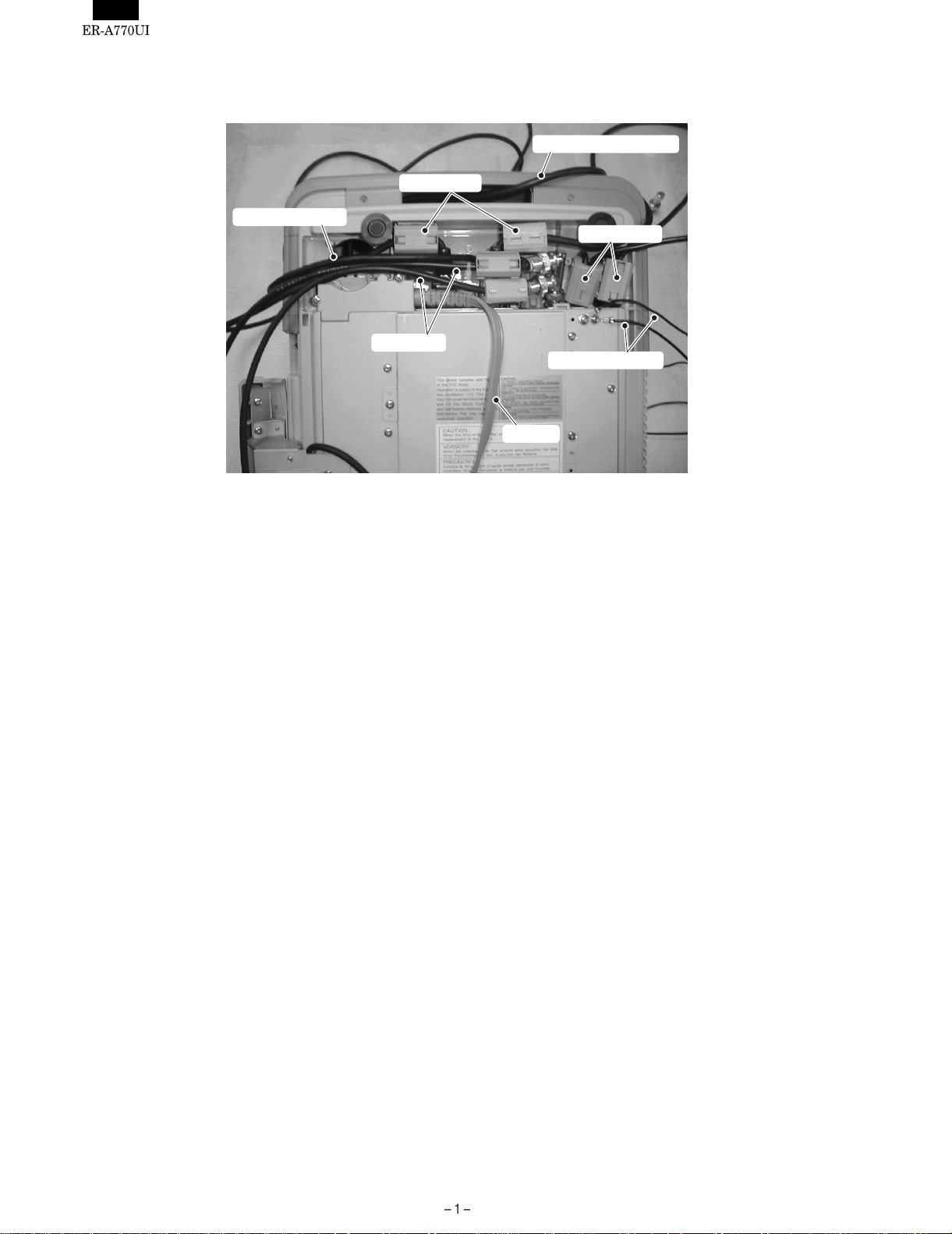
Example of wiring for all optional devices connected to the system unit.
ERA-7RS (RS232) cable
RS232 cable
UP-P16DP cable
Drawer cable
Inline cable
Drawer earth cable
AC cord
Page 3
Precautions
• Before installation, be sure to disconnect the AC power.
• Use gloves to protect your hands from being cut by the angle
and the chassis.
• Connect all the cables securely. When connecting or
disconnecting the cables, be careful not t o apply st ress to t he
cables. (It may cause disconnection.)
• Ground the human body to eliminate static electricity. When
assembling the LCD, use a discharge blower to prevent the
introduction of dust.
• Be careful when working near the high voltage transformer.
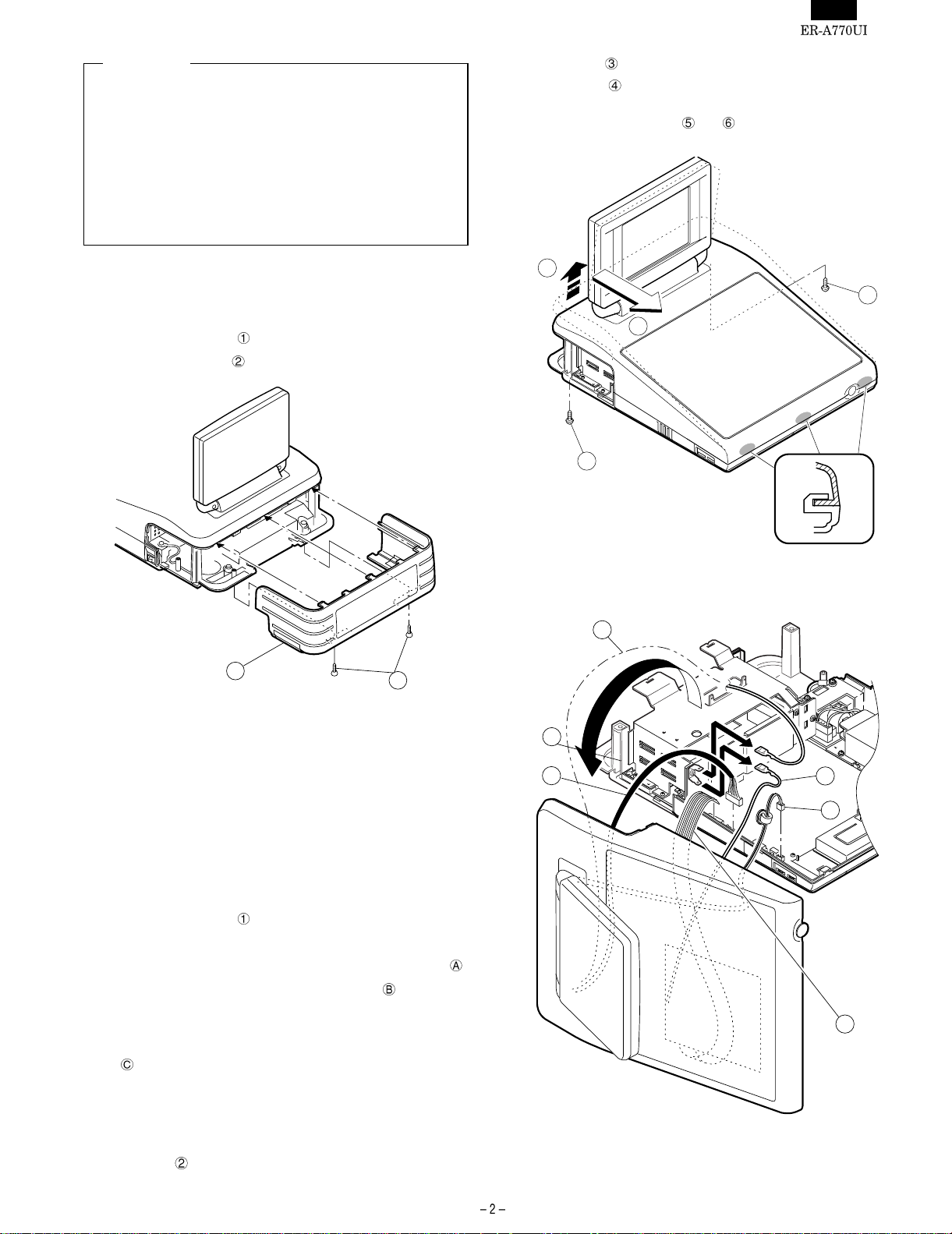
• Cable between the main PWB and the LCD: (CN10)
• Cable between the main PWB and the CKDC PWB:
(CN8)
e) Remove the earth wire
A
and .
1. Removing the rear cover
1) Remove the two screws fixed on the lower cabinet.
2) Remove the rear cover
.
2
Fig. 1
1
B
1
Fig. 2
5
1
C
2. Replacing the rear cover
Install the rear cover in the reverse order of removing.
3. Removing the top cabinet
1) Remove the two screws fixed on the lower cabinet.
2) Remove the top cabinet.
a) Lift the rear edge of the top cabinet in the direction of arrow
b) Slide the top cabinet in the direction of arrow
three pawls of the bottom cabinet at the same time. (Be care-
ful not to break the pawls.)
c) Lift the top cabinet and put it straight in the direction of arrow
.
(Be careful not to pull the cable between the top cabinet
and the main PWB.)
d) Pull and remove the following cables between the top cabinet
and the main PWB.
• Cable between the main PWB and the invertor PWB:
(CN13)
and remove
3
.
Fig. 3
6
2
4
Page 4

4. Replacing the top cabinet
6. Replacing the Noise filter PWB
Install the top cabinet in t he reverse order of removing. Bef ore instal ling, make sure that each connector is connected securely.
5. Removing the Noise filter PWB,
Transformer and AC cord
1) Remove the two screws .
2) Remove the AC cord cover
3) Remove the screw
4) Use a minus screwdriver to loosen the AC cord fixing screws (2
pcs.) of the Noise filter PWB.
5) Pull out the AC cord
6) Remove the connector
4
.
and the earth wire .
from the Noise filter PWB.
.
3
6
and Transformer
Install the power supply unit in the reverse order of remo ving. Before
installing, make sure that each connector is connected securely.
When connecting the AC cord to the power supply unit in assembly, tighten with the torque of 3 kg/cm
1 kg/cm
7. Removing and replacing the
keyboard unit
The keyboard unit is fixed to the top cabinet with screws.
1
21
20
CKDC PWB ANGLE
65432
7
8
22
19
5
18
17
16
15
14 13
23
12
9
10
11
Fixed
Screw parts
code
Boss
No.
Fixing position
Earth wire – PWB angle – Keyboard unit –
Top cabinet
Earth wire – PWB angle – Keyboard unit –
Top cabinet
Earth wire – PWB angle – Keyboard unit –
Top cabinet
PWB angle – Keyboard unit – Top cabinet
PWB angle – Keyboard unit – Top cabinet
2
Holder – PWB angle – Keyboard unit –
Top cabinet
Earth spring – PWB angle – Keyboard unit
– Top cabinet
PWB angle – Clerk cover – Top cabinet
PWB angle – Clerk cover – Top cabinet
1
PWB angle – Keyboard unit – Top cabinet
PWB angle – Keyboard unit – Top cabinet
Holder – PWB angle – Keyboard unit –
Top cabinet
Fig. 4
Holder – PWB angle – Keyboard unit –
Top cabinet
Page 5

8. Removing and replacing the LCD
9. Expansion RAM Board :
unit
1) Remove the four fixing screws of the display unit from the top
cabinet
.
2
3
UP-P02MB2
Make sure to save data before installing this option.
Also make sure the capacitor (C32) is positioned in the direction opposite the connector ; otherwise the capacitor might
hinder the insertion of the expansion RAM board.
1) Remove the top cabinet.
2) Install the Expansion RAM Board
on the Main PWB.
a) Insert the Expansion RAM Board into the option RAM connector.
b) Insert that the Expansion RAM Board is locked by the arms of
option RAM connector as s indicated in Fig 7.
It is possible to install one UP-P02MB2.
Install the Expansion RAM Board with the notch part of the
PWB (Figure A) come right. Installing the Expansion RAM
Board in the wrong direction may damage the connector
part or make the machine out of order.
A
to the Option RAM connector
1
3
Fig. 5
2) Remove the two fixing screws
unit.
3) The LCD unit is assembled with seven pawls. Remove the pawls
in the order of
to as shown in the figure.
c
of the LCD unit in the display
LCD cabinet hear side
de
b
a
1
f
g
Fig. 7
3) Removing the Expansion RAM Board.
a) Open the arms of option RAM connector right and left.
b) The Expansion RAM Board will be lifted automatically.
10. RS232 I/F: ER-A7RS
4
Fig. 6
1) Remove the rear cover.
2) Remove the two screws
3) Insert the I/F PWB
4) Fix the I/F bracket to the chassis with screws
5) Install the ferrite core
6) Install the Nylon band
from the chassis.
to the connector.
.
to the cables.
.
Page 6

12. Drawer box unit: ER-03DW/04DW
2
ER-A7RS
3
4
RS232 cable
ER-A7RS
1
3
4
RS232 cable
Fig. 8
11. MCR unit: UP-E12MR
1) Fix the MCR angle to the lower cabinet with two screws .
2) Remove the three screws
3) Remove the HDD cover
4) Connect the MCR cable
the MAIN PWB.
5) Fit the MCR cable
install the HDD cover
6) Fix the three screws
3
.
.
to the MCR connector: CN18 on
to the slit part of the bottom cabinet to
.
.
4
2
1
1) Connect the drawer cable to the drawer connector .
2) Fix the earth wire
from drawer box unit with the screw .
1 turn
Fig. 10
3) Install the ferrite Core to the drawer cable.
4) Fix the drawer cable
screw
on the back of lower cabinet or .
with the cable holder , and tighten the
13. Customer display: UP-I16DP
1) Remove the rear display cover.
5
A
6
Fig. 9
2) Change the display filter.
Fig. 11
Page 7

3) Insert the UP-I16DP on the two latches of the lower cabinet.
4) Raise the UP-I16DP toward you and put the two latches
the chassis.
BB
A
A
into
B
A
Fig. 12
Cautions: When installing the UP-I16DP on the lower cabinet,
align it with the line of the lower cabinet. Make sure it
settles inside the latch.
UP-I16DP
Fig. 13
7) Install the core on the cable and secure the cable with the clamp.
8) Install the display cover.
14. Remote display: UP-P16DP
When the remote display is installed, service resetting is required.
1) Connect to the Display cable
2) Fix the earth wire
from the display unit with screw .
to the display connector .
Lower cabinet
5) Make sure the display cable passes under it.
6) Connect to the display cable to the display connector.
Fig. 14
Note : The ER-A770 can only support 1 type customer display at
a time either the UP-I16DP or UP-P16DP.
Page 8

15. How to extend display pole:
UP-P16DP
The pole can be extended by installing the attached pole to the
standard pole.
COMPONENT LIST:
No. NAME USE Q’ty
Pole cabinet Pole extension 2
Screw (M2 x 8) Pole connection 4
Screw (M4 x 16)
Screw (M4 x 20)
Nut
Securing the UP-P16DP to the
wooden table
Securing the UP-P16DP to the
metal table
Securing the UP-P16DP to the
metal table
4
4
4
5) Turn the ratchet
position and pull it out from the display unit
6) Remove the two screws
7) Remove the pole cabinet
8
connected to the pole cabinet to the removing
.
from the Ratchet .
10
9
as shown in Fig. A.
1) Remove the five screws
2) Remove the Base angle
2
1
1
3) Remove the two screws
4) Remove the Base cabinet
.
.
Fig. 15
.
from the pole cabinet .
7
8) Install the attached pole cabinet
with the screw
Display cable
7
10
Fig. 17
.
7
12
12
9
Fig. A
to the pole cabinet to fix it
7
4
11
11
Fig. 18
6
Fig. 16
9) Install the pole cabinet
bly.
in the opposite order of the disassem-
Page 9

10) Fastening onthe table:
Secure the Base cabinet
using the screw.
16. SRN I/F: Standard
No. NAME USE Q’ty
Screw (M4 × 16)
Screw (M4 × 20)
Nut
15
Securing the UP-P16DP to the
wooden table
Securing the UP-P16DP to the
metal table
Securing the UP-P16DP to the
metal table
13 13
14
14
15
4
4
4
Fig. 19
1) Connect to the SRN cable to the SRN connector .
2) Install the Ferrite core
3) Install the Nylon band
to the SRN cable .
to the SRN cable .
Using the terminal resistor (50 ohm: QCNCM7145RCZZ).
Insure that the system is terminated at each.
Fig. 21
Terminator
Ω
50
R
*Master Satellite Satellite
Trunk cables
Branch
cables
(5m x 2)
16.4ft.
x 2
Satellite Satellite
Terminator 50
Cable conector
JJ conector
Ω
R
Lowering the height of the UP-P16DP
Remove the standard Pole and attach the Base cabinet to the
Ratch
.
Fig. 20
17. RS232 I/F: Standard
1) Connect the RS232 cable to the connector.
2) Install the ferrite Core
3) Install the ferrite core
to RS232 cable.
to the cables.
Fig. 22
Page 10

COPYRIGHT 2000 BY SHARP CORPORATION
All rights reserved.
Printed in Ja pan.
No part of this public ation may be reproduced,
stored in a retrieval system, or transmitted.
In any form or by any means ,
electronic, mechanical, photocop ying, recording, or oth erwise,
without prior written permission of the publisher.
SHARP CORPORATION
Information Systems Group
Quality & Reliability Control Center
Yamatokoriyama, Nara 639-1186, Japan
2000 May Printed in Japan
 Loading...