

Page 1

POS TERMINAL
MODEL
ER-A750
INTER-REGISTER
COMMUNICATION SYSTEM
INSTRUCTION
MANUAL
Page 2

TABLE OF CONTENTS
Introduction ......................................................................................................................... 3
1
IRC Programming................................................................................................................ 4
1. Setting machine numbers — master and satellite.......................................................... 4
2. Setting terminal numbers (IRC machine numbers) — master and satellite................... 5
3. Creating/updating the master list — master................................................................... 6
(1) Creating the master list (subwindow program)......................................................... 6
(2) Deleting a machine from the master list (subwindow program)................................ 7
4. Specifying the terminal to serve as a backup master — master.................................... 8
5. Specifying whether to enable or disable the system retry function
when a transmission error occurs — master and satellite ............................................. 9
6. Specifying whether to enable or disable the entry function
when the T-LOG buffer becomes full — master and satellite ........................................ 10
7. Reading the contents of IRC programming — master and satellite............................... 11
8. Downloading the contents of the IRC programming to satellites — master................... 13
(1) Initial downloading.................................................................................................... 13
(2) Maintenance downloading........................................................................................ 14
9. Programming for the remote printer............................................................................... 17
(1) Assigning remote printer numbers to remote printers — master and satellite.......... 17
(2) Specifying whether to enable or disable the function for
data transmission to the romote printer — master and satellite............................... 18
(3)
Selecting the receipt type (additional or single/double type) — master and satellite
(4) Assigning the second remote printer number to each remote printer
— master and satellite.............................................................................................. 19
(5) Naming the remote printer — master and satellite................................................... 19
(6) Specifying the format of printing — master and satellite .......................................... 20
10. Reading the contents of the remote printer programming — master and satellite......... 21
11. Downloading the contents of the remote printer programming to satellite — master .... 22
12. Programming for the drink dispenser sales function (option)......................................... 23
(1) Choosing whether to set the local on-line or off-line mode
for the drink dispenser.............................................................................................. 23
(2) Notes on the programming for the drink dispenser(s) in the IRC system................. 24
13. Reading the contents of the programming for the drink dispenser
sales function (PGM2 mode).......................................................................................... 25
...... 18
Page
2
Inline Operation ................................................................................................................... 26
1. Message display ............................................................................................................ 26
(1) The message displayed during inline operation ....................................................... 26
(2) Error messages ........................................................................................................ 27
2. Open store operation (PGM2 mode) — master and satellite......................................... 28
3. Close store operation (PGM2 mode) — master and satellite......................................... 29
4. Sign-on operation (clerk assignment) ............................................................................ 30
5. Sign-off operation (cancellation of clerk assignment) .................................................... 31
6. Clerk system ..................................................................................................................32
1
Page 3

7. Clerk sign-on report........................................................................................................ 33
8. Look-up and updating of the GLU/PBLU file.................................................................. 34
9. Drive-through function.................................................................................................... 35
10. T-Log polling .................................................................................................................. 36
11. Communication with a remote printer (option)............................................................... 37
12. Rerouting receipt/journal print data................................................................................ 38
3
Consolidated and Individual Reports................................................................................... 39
1. Operating modes............................................................................................................ 39
2. Job code......................................................................................................................... 39
3. Consolidated reports — master/back-up master............................................................ 40
(1) Report generation procedure.................................................................................... 40
(2) List of consolidated reports (SYSTEM READING/RESETTING) ............................. 41
4. Individual reports — master/back-up master/satellite.................................................... 44
(1) Report generation procedure.................................................................................... 44
(2) List of individual reports (READING/RESETTING) .................................................. 45
5. Clerk report .................................................................................................................... 48
6. Reports that can be generated when the Compulsory Cash/Cheque Declaration
(CCD) function is enabled.............................................................................................. 50
7. Reset clear operation (X1/Z1 and X2/Z2 modes) — master.......................................... 52
4
System Back-Up.................................................................................................................. 54
1. How the IRC back-up system works.............................................................................. 54
2. Master declaration — when the master or back-up master breaks down...................... 55
(1) When the master breaks down — Master declaration at the back-up master.......... 55
(2) When the back-up master breaks down — Master declaration at the master.......... 57
3. Recovery declaration
— when the master or back-up master recovers from breakdown ................................ 58
(1) When the master recovers from a breakdown
— Recovery declaration at the back-up master ....................................................... 58
(2) When the back-up master recovers from a breakdown
— Recovery declaration at the master..................................................................... 60
5
Error Recovery..................................................................................................................... 61
1. Manual clear operation................................................................................................... 61
(1) Manual clearing of the sign-on state — master........................................................ 61
(2) Manual clearing of the GLU/PBLU data in use — master ........................................ 62
(3) Manual clearing of the drive through data in use — master..................................... 62
(4) Manual clearing of the department/transaction memory — master and satellite...... 62
(5) Manual clearing of the clerk sales data memory — master and satellite ................. 62
(6) Manual clearing of the hourly sales data memory — master and satellite ............... 63
(7) Manual clearing of the daily net sales data memory — master and satellite............ 63
(8) Manual clearing of the T-LOG buffer — master satellite .......................................... 63
2. System retry function ..................................................................................................... 64
Basic Specifications............................................................................................................. 66
6
Handling the Remote Printer ............................................................................................... 67
2
Page 4
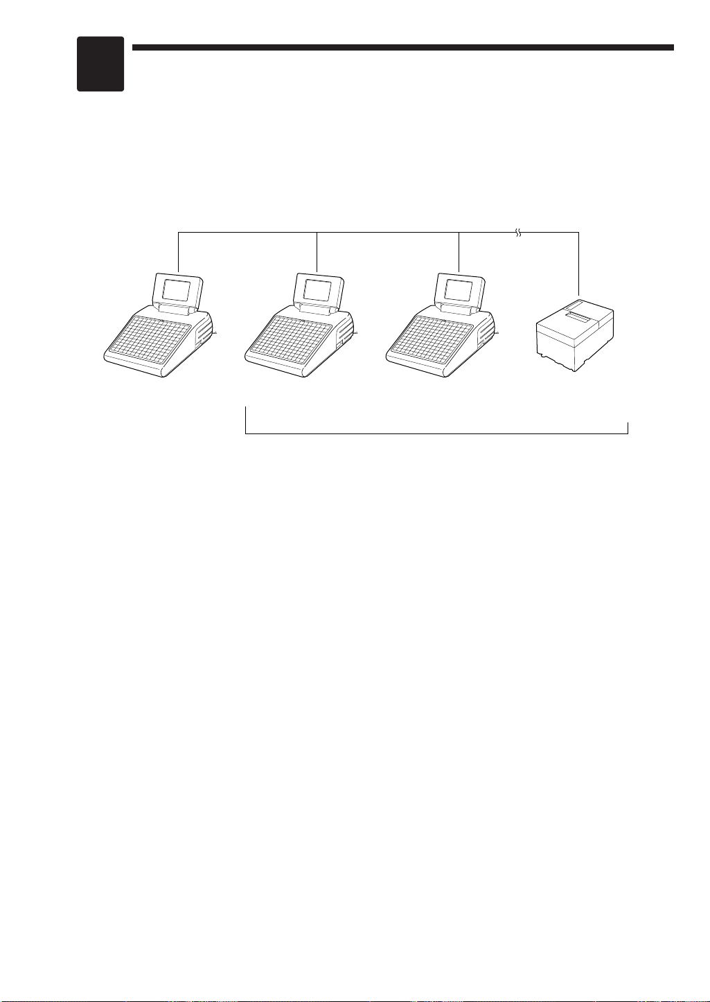
Sharp Retail Network
Master Satellite Satellite Remote Printer
(max. 9 remote printers)
Max. 15 satellites/remote printers
Introduction
The ER-A750 inter-register communication (IRC) system consists of one master machine and up
to 15 satellite machines/remote printers (max. 9 remote printers) which are all interconnected by
the Sharp Retail Network (SRN) to provide data transmission among them. This system allows
the manager to exercise centralized control over the satellites through the master.
• One of the satellites may be used as a back-up master.
3
Page 5
1
IRC Programming
First, turn on the machines in the IRC system and put them in the PGM2 mode. The
programming procedures for both the master and satellites will be explained below.
1. Setting the machine numbers – master and satellite
It is necessary to assign machine numbers to the master and satellites before the IRC
programming.
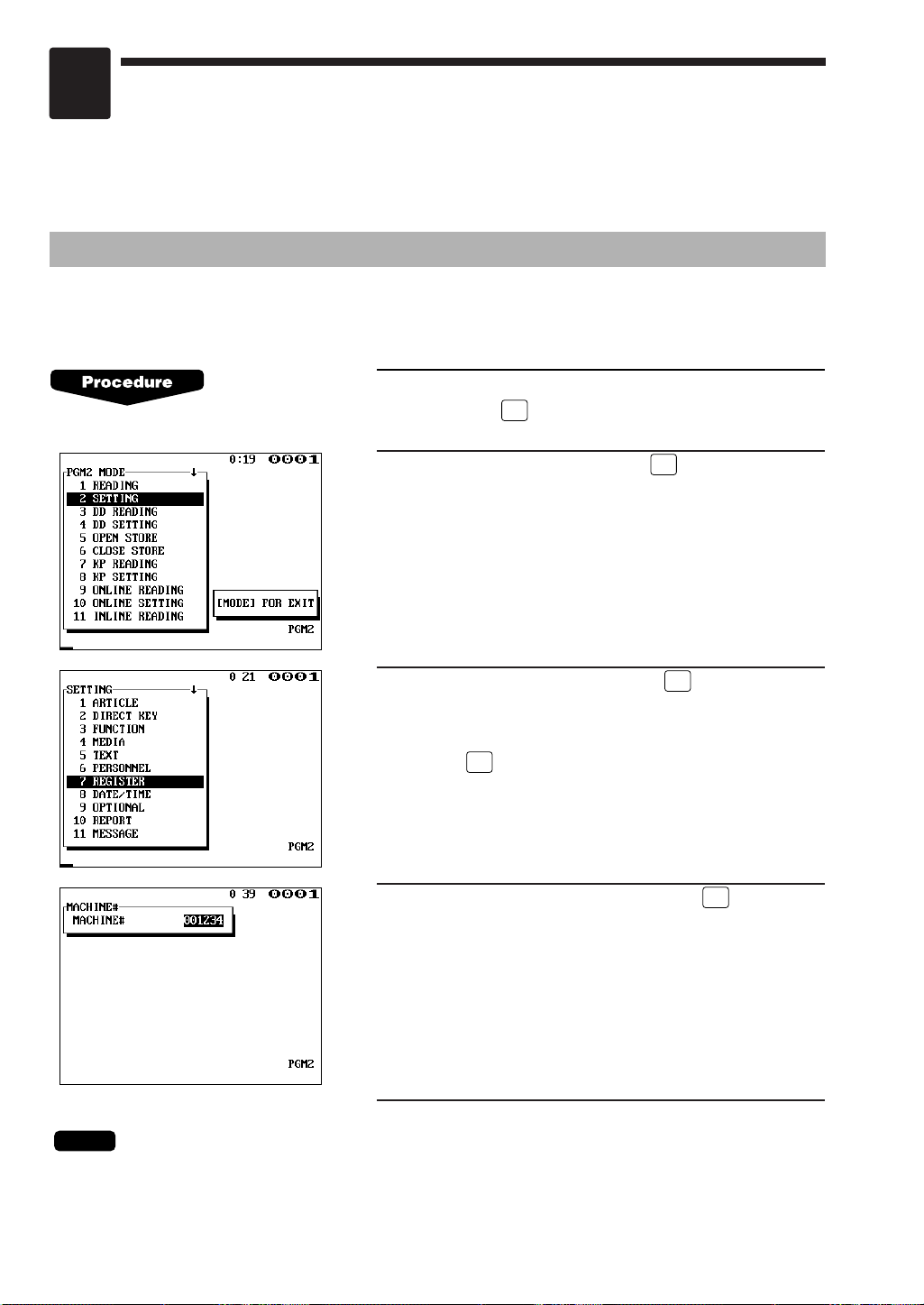
1.
Select “PGM2 MODE” from the mode selection window
and press the key to enter the PGM2 mode.
ENTER
2.
Select “SETTING” and press the key.
3.
Select “REGISTER” and press the key. The
REGISTER window will open.
Select “MACHINE#” from the REGISTER window and
press the key.
4.
Enter a machine number and press the key.
Machine number: up to 6 digits (0–999999)
ENTER
ENTER
ENTER
ENTER
5.
Repeat steps 1 to 4 for all machines in the IRC system.
NOTE
In an IRC network, each machine number must be unique.
Do not use the same number for more than one machine.
4
Page 6
NOTE
ENTER
ENTER
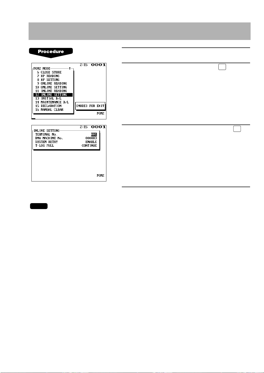
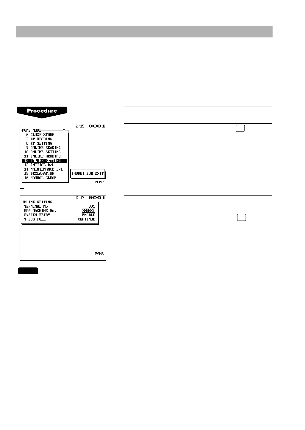
2. Setting the terminal numbers (IRC machine numbers) –
master and satellite
1.
Enter the PGM2 mode.
2.
Select “INLINE SETTING” and press the key.
3.
Enter a terminal number (0–254) and press the
key.
(For programming for BMA MACHINE No., SYSTEM
RETRY and T-LOG FULL, see pages 8–10.)
4.
Repeat steps 1 to 3 for all machines in the IRC system.
• Terminal numbers must be assigned to the master and each satellite in the IRC system.
(For setting the master’s terminal number, see the next paragraph.)
• If an inline network contains two or more machines with the same terminal number, inline
communications will not be achieved correctly. Each terminal number must be unique.
• The terminal number should be within the range from 1 to 254.
• If the terminal number “000” is programmed for a machine, it is put in the OFF LINE mode and
cannot take part in inline communications.
5
Page 7
TL
ENTER
ENTER
ENTER
ENTER
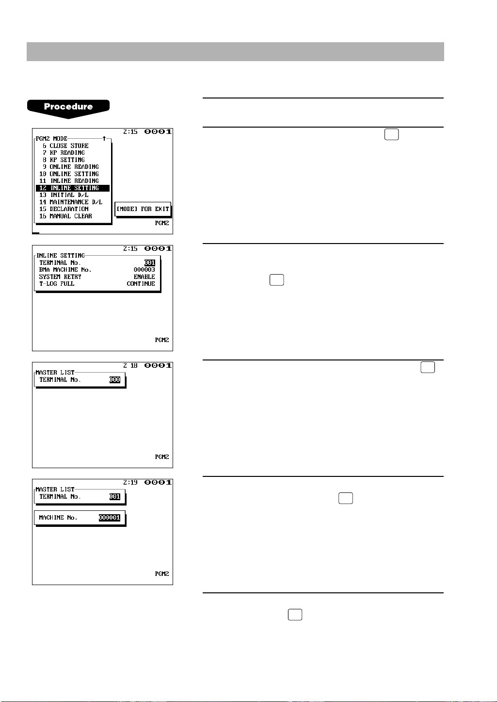
3. Creating/updating the master list – master
(1) Creating the master list (subwindow program)
1.
Enter the PGM2 mode.
2.
Select “INLINE SETTING” and press the key.
3.
Enter a terminal number (0–254) for the master, carry
out the programming for other INLINE SETTING items
and press the key. The subwindow for the creation
of the master list will open.
(For programming for BMA MACHINE No., SYSTEM
RETRY and T-LOG FULL, see pages 8–10.)
4.
Enter the terminal number (1–254) and press the
key. The subwindow for machine number entry will
open.
5.
Enter the machine number (1–999999) of a machine in
the IRC system and press the key.
6.
Repeat steps 4 to 5 for all machines in the IRC
system. Press the key to complete the master list.
6
Page 8

• The terminal numbers and machine numbers of the master and satellites must be entered into
NOTE
DELTLENTER
ENTER
NOTE
the master list for inline communications.
• The terminal numbers and machine numbers of up to 16 machines (one master and 15
satellites) can be entered into the master list.
• The terminal number should be within the range from 1 to 254 and the machine number from 1
to 999999.
• No satellite can perform inline communications unless its terminal and machine numbers are
present in the master list.
• If a machine number which already exists in the master list is entered, a lock error will occur
even when the corresponding terminal number does not exist in the list.
(2) Deleting a machine from the master list (subwindow program)
To delete a terminal number from the master list, proceed as follows:
1. Select “PGM2 MODE” from the mode selection window and press the key to enter
the PGM2 mode.
2. Select “INLINE SETTING” and press the key. The INLINE SETTING window will
open.
3. Press the key. The subwindow for the master list will open.
4. Enter the terminal no. to be deleted and press the key.
5. The machine will ask you as follows: “ARE YOU SURE?” If you are sure to delete it,
select “YES”. If not, select “NO”.
• You can delete any of the terminal numbers that are in the master list.
7
Page 9
NOTE
ENTER
ENTER
4.
Specifying the terminal to serve as a back-up master –master
You can assign one satellite to the function of a back-up master. If the master fails during guest
check operation, the assigned terminal will perform the master’s function.
A machine number within the range from 1 to 999999 can be entered.
If zero is entered, there will be no back-up master in the IRC system.
This job can be done in the INLINE SETTING window of the master.
The default setting is 0 (no back-up master).
1.
Enter the PGM2 mode.
2.
Select “INLINE SETTING” and press the key.
The INLINE SETTING window will open.
3.
Move the cursor to the “BMA MACHINE NO.” line.
Then enter the machine number of the terminal to
serve as a back-up master and press the key.
The DECLARATION functions in the PGM2 mode enable the back-up master or the master to
declare to be the master when the master or back-up master breaks down, and inform satellites
of the master’s or back-up master’s recovery.
For details of these functions, see “Master declaration” and “Recovery declaration” on pages
55–60.
8
Page 10
NOTE
ENTER•ENTER
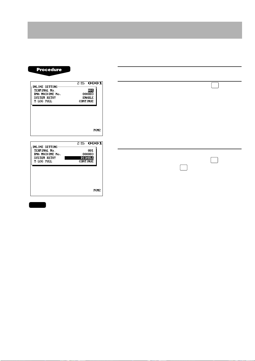
5.
Specifying whether to enable or disable the system retry function
when a transmission error occurs – master and satellite
You can specify whether the system retry function is disabled or enabled if the communication
between machines does not end successfully.
1.
Enter the PGM2 mode.
2.
Select “INLINE SETTING” and press the key.
The INLINE SETTING window will open.
3.
Move the cursor to the “SYSTEM RETRY” line.
Select “DISABLE” or “ENABLE” with the key
(toggle key) and press the key.
• If the system retry function is enabled, a transmission job with which an error has occurred is
not finalized immediately, but the master waits for selection of one of the three commands
(RETRY, ABORT and IGNORE) through the keyboard or menu. Then the master retries
access to the satellite that has caused the transmission error or terminates the access as a
successful or unsuccessful transmission depending on the selection made.
• If the function is disabled, the job is terminated immediately.
• For further information, see “System retry function” on pages 64–65.
• The default setting is “ENABLE”
9
Page 11
NOTE
ENTER•ENTER
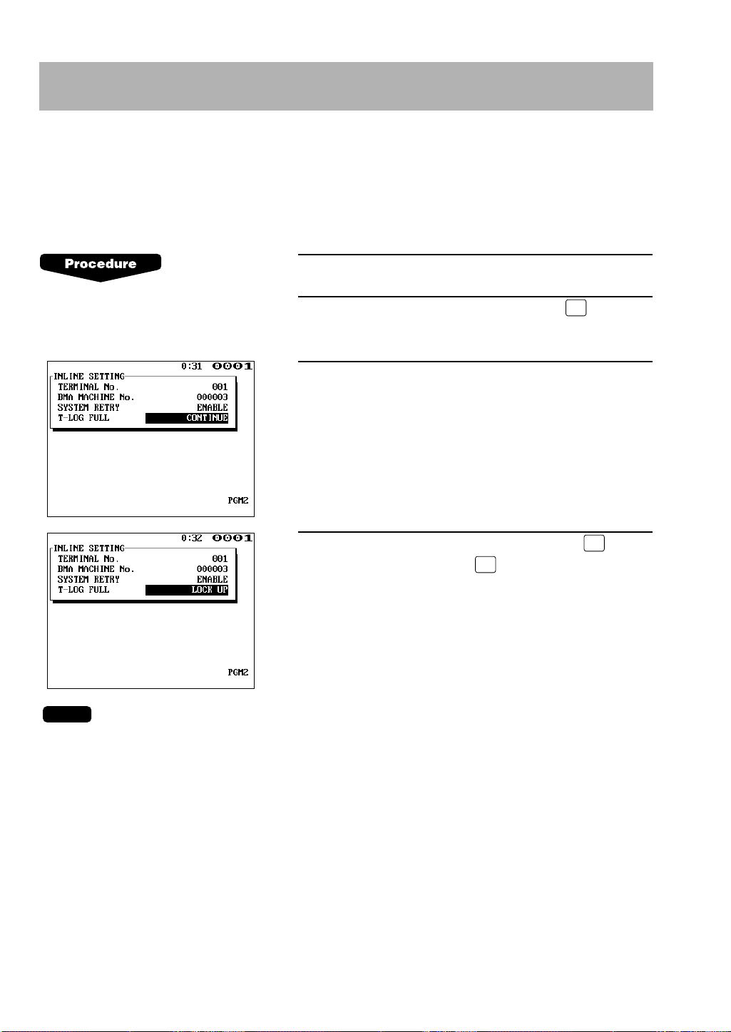
6. Specifying whether to enable or disable the entry function
when the T-LOG buffer is full – master and satellite
You can specify whether the entry function of a satellite is disabled (LOCK UP) or enabled
(CONTINUE) when the T-LOG buffer is full. If it is disabled, an error message will be displayed
when you try any entry in the REG/MGR mode at the satellite. If it is enabled, you can continue
entries but cannot save the entered data. Even if data is entered after the T-LOG buffer becomes
full, the data saved in the file will not be erased.
1.
Enter the PGM2 mode.
2.
Select “INLINE SETTING” and press the key.
The INLINE SETTING window will open.
3.
Move the cursor to the “T-LOG FULL” line.
4.
Select “CONTINUE” or “LOCK UP” with the key
(toggle key) and press the key.
• The T-LOG buffer is provided in each satellite to store the data to be transmitted to the master
by T-LOG polling. The data is automatically transmitted to the master in the open store state.
For more information about T-LOG polling, see “T-LOG polling” on page 36.
• When the entry function is disabled, “LOCK UP” will be printed on the receipt.
• When the entry function is enabled, “CONTINUE” will be printed on the receipt.
• The default setting is “CONTINUE”.
10
Page 12
ENTER
ENTER
ENTER
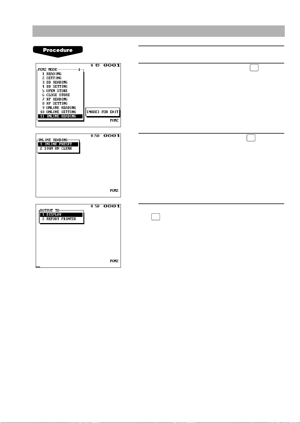
7.
Reading the contents of the IRC programming – master and satellite
1.
Enter the PGM2 mode.
2.
Select “INLINE READING” and press the key.
The INLINE READING window will open.
3.
Select “INLINE PRESET” and press the key.
4.
Select “DISPLAY” or “REPORT PRINTER” and press
the key.
11
Page 13
• You can also read the same contents of the IRC programming on the display screen.
I NL I NE PRESET
T–NO.
001
SYSTE
M
RETRY ENABLE
T–LOG FULL CONTINUE
∗PGM2∗ ∗PGM2∗
I NL I NE PRESET
T–NO. 001
M
ASTER LIST
T–NO.
001
002
003
004
005
M
–NO.
000001#
000002#
000003#
000004#
000005#
BACK UP
M
ASTER
T–NO.
002
M
–NO.
000002#
SYSTE
M
RETRY ENABLE
T–LOG FULL CONTINUE
Terminal number of the master
Terminal number of the satellite
System retry function
(enable/disable)
The state of the satellite when
the T-LOG buffer becomes full
(continue/lock up)
SamplePrint (master) SamplePrint (satellite)
List of the machines involved in the IRC system
(terminal no./machine no.)
Back-up master
(terminal no./machine no.)
System retry function
(enable/disable)
The state of the master when
the T-LOG buffer becomes full
(continue/lock up)
12
Page 14
•
NOTE
ENTER
ENTER
ENTER
ENTER
ENTER
8. Downloading the contents of the IRC programming to
satellites – master
When you have completed the IRC programming, distribute the IRC preset data from the master
to all satellites in the IRC system.
(1) Initial downloading
For initial setup of the IRC system, use this downloading method. The preset data in the
master is downloaded to each satellite, when the existing preset data in the satellite is
cleared.
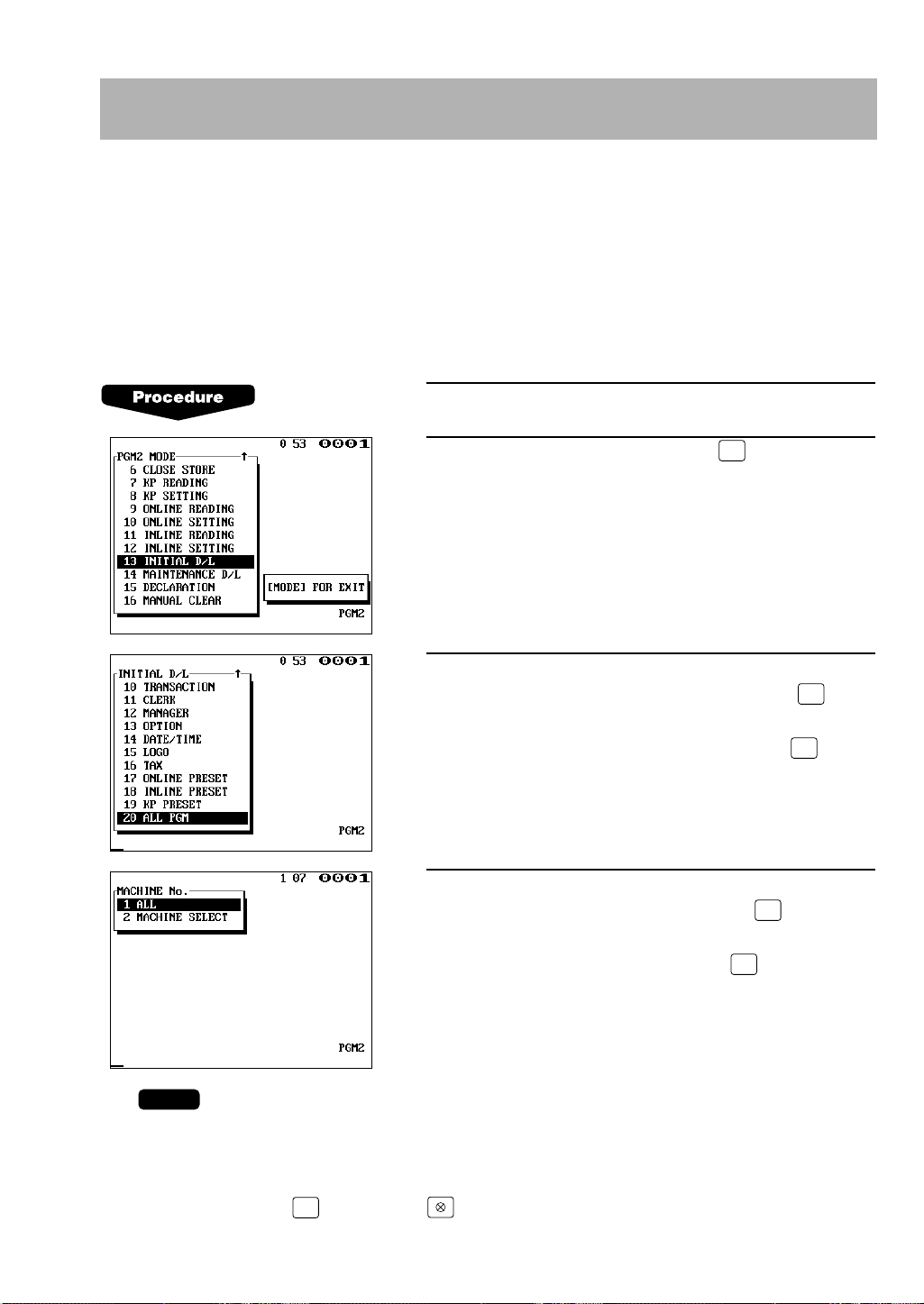
1.
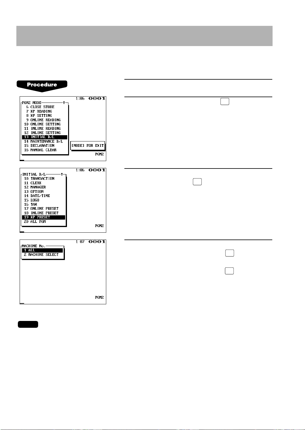
Enter the PGM2 mode.
2.
Select “INITIAL D/L” and press the key.
The INITIAL D/L window will open.
3.
In order to distribute all preset data files in the master
to satellites, select “ALL PGM” and press the key.
In order to distribute an individual preset data file,
select the corresponding item and press the key.
If needed, enter the code range.
4.
If you wish to download the IRC programming data to
all satellites, select “ALL” and press the key. If you
wish to download the data to certain satellite(s), select
“MACHINE SELECT” and press the key. In this
case, the MACHINE SELECT window will open. Move
the cursor to the desired machine number and select
“YES”.
• Check the contents of the programming of all the satellites in the IRC system that have
received the preset data.
• If you want to download by entering a job code, enter a job code listed in the table on page
15 and press the key and the key in the PGM2 mode window.
13
Page 15
(2) Maintenance downloading
ENTER
ENTER
ENTER
ENTER
To update preset data for the IRC system, use this downloading method. The preset data in
the master is downloaded to each satellite without clearing the existing preset data.
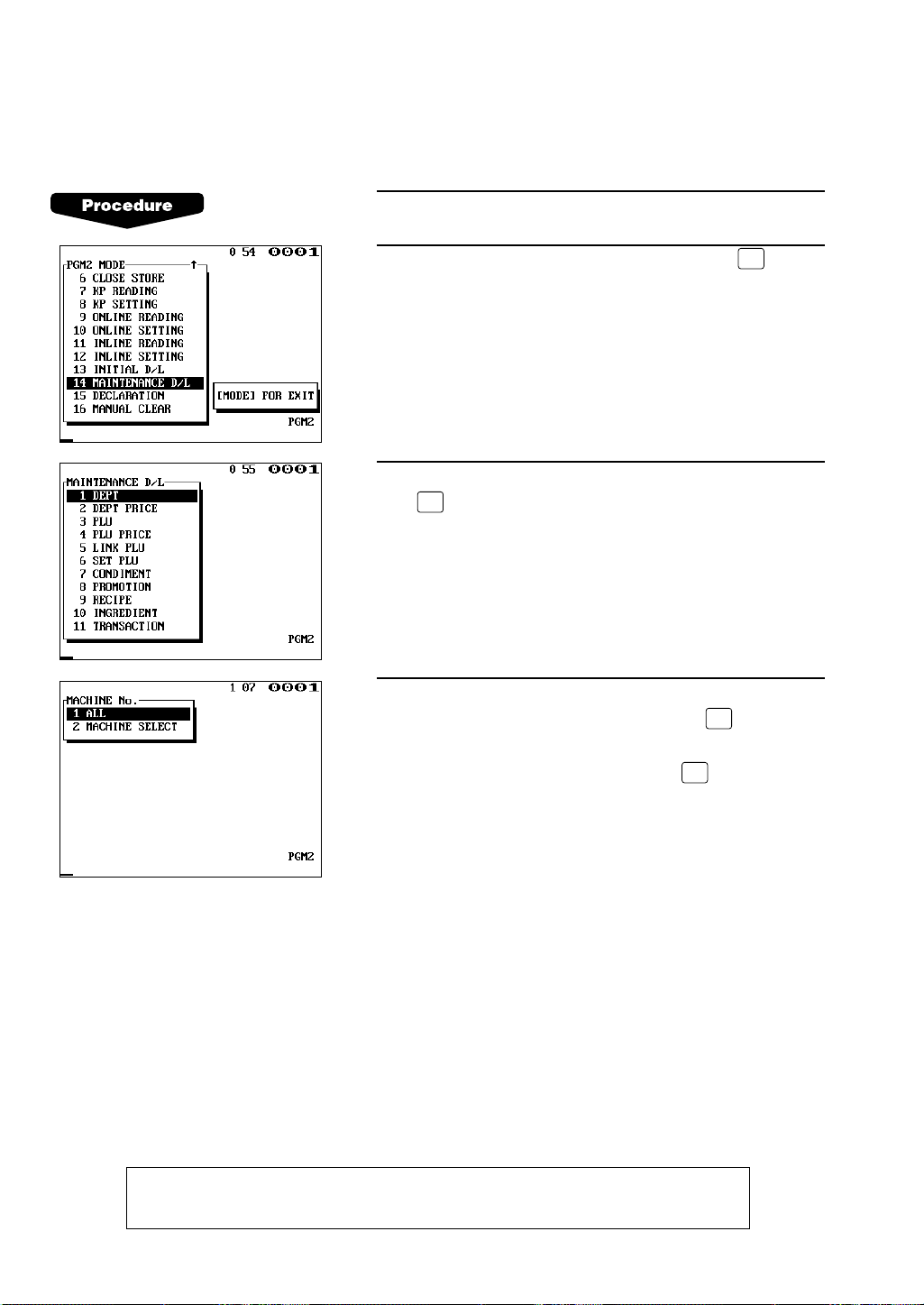
1.
Enter the PGM2 mode.
2.
Select “MAINTENANCE D/L” and press the key.
The MAINTENANCE D/L window will open.
3.
Select a preset data item for maintenance and press
the key.
If needed, enter the code range.
4.
If you wish to download the IRC programming data to
all satellites, select “ALL” and press the key. If you
wish to download the data to certain satellite(s), select
“MACHINE SELECT” and press the key. In this
case, the MACHINE SELECT window will open. Move
the cursor to the desired machine number and select
“YES”.
WARNING: Avoid downloading data while a REG/MGR-mode entry is made at the
satellite.
14
Page 16

List of downloading jobs (PGM2 mode)
NOTE
Menu
INITIAL D/L 4100 DEPT Department preset data Preset data copying with clearing
MAINTENANCE
D/L
Job code
4119 DIRECT KEY
4200 PLU PLU/Link PLU/Set PLU Preset data copying with clearing
4220 LINK PLU LINK PLU preset data Preset data copying with clearing
4221 SET PLU Set PLU preset data Preset data copying with clearing
4223 CONDIMENT
4225 PROMOTION Promotion preset data Preset data copying with clearing
4226 RECIPE Recipe preset data Preset data copying with clearing
4227 INGREDIENT Ingredient preset data Preset data copying with clearing
4300 TRANSACTION Transaction preset data Preset data copying with clearing
4400 CLERK Clerk preset data Preset data copying with clearing
4450 MANAGER Manager preset data Preset data copying with clearing
4600 OPTION Other preset data Preset data copying with clearing
4610 DATE/TIME Date, time Preset data copying with clearing
4614 LOGO Message preset data Preset data copying with clearing
4700 TAX Tax preset data Preset data copying with clearing
4800 ONLINE PRESET Online preset data Preset data copying with clearing
4900 INLINE PRESET Inline preset data Preset data copying with clearing
4950 KP PRESET Remote printer preset Preset data copying with clearing
4999 ALL PGM All PGM-mode preset Downloading of Job #4100 to 4950
5100 DEPT Department preset data Only preset data copying
5110 DEPT PRICE Department price preset Only preset data copying
5200 PLU PLU/Link PLU/Set PLU Only preset data copying
5210 PLU PRICE PLU price preset data Only preset data copying
5220 LINK PLU Link PLU preset data Only preset data copying
5221 SET PLU Set PLU preset data Only preset data copying
5223 CONDIMENT
5225 PROMOTION Promotion preset data Only preset data copying
5226 RECIPE Recipe preset data Only preset data copying
5227 INGREDIENT Ingredient preset data Only preset data copying
5300 TRANSACTION Transaction preset data Only preset data copying
Item Description Note
Dept./PLU key preset data
for direct depts./PLUs
preset data
Condiment PLU preset data
data
data is performed collectively.
data
preset data
Condiment PLU preset data
Preset data copying with clearing
Only preset data copying
• The PLU/Link PLU/Set PLU file (INITIAL D/L and MAINTENANCE D/L) does not include stock
data.
• The PLU/Link PLU/Set PLU file (INITIAL D/L and MAINTENANCE D/L) includes LINK PLU and
SET PLU preset data.
15
Page 17

• The TRANSACTION file includes the following data:
Function programming, Media programming
• The OPTION file includes the following data:
Optional feature preset, stacked report, auto key, GLU code range, Job location table,
Department shift, and Happy hour.
• The LOGO file includes the following data:
Logo text, slip text, department group text, PLU group text, free text, currency descriptor
and payee name.
16
Page 18
ENTER
9. Programming for the remote printer
For connection of remote printers to the SRN, be sure to consult your dealer.
(1) Assigning remote printer numbers to the remote printers – master and
satellite
With the following procedure, you can do programming for the remote printers connected to
the SRN.
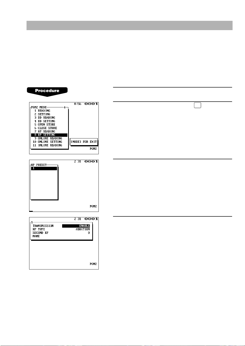
1.
Enter the PGM2 mode.
2.
Select “KP SETTING” and press the key. The KP
SETTING window will open.
3.
Select the remote printer number to be programmed.
4.
Carry out the programming for the remote printer.
(See the following pages for programming for individual
remote printer items.)
17
Page 19
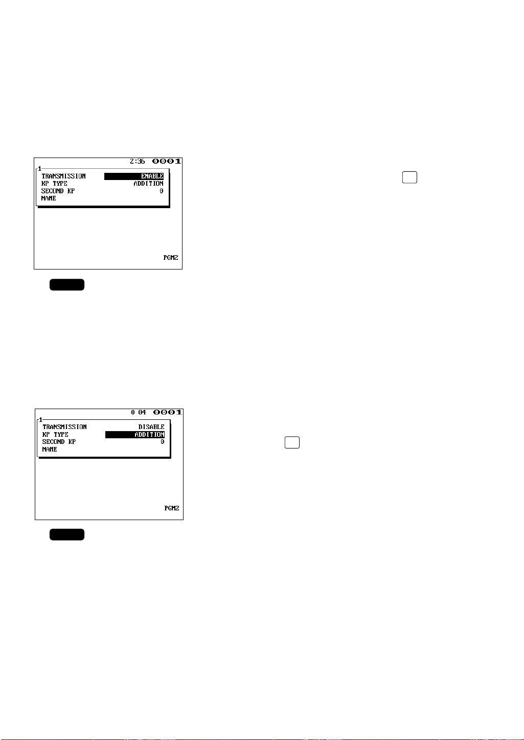
(2) Specifying whether to enable or disable the function for data
NOTE
•
NOTE
•
transmission to the remote printer – master and satellite
If a remote printer is disconnected from the IRC system or any other problem occurs in it,
you can disable your machine to stop data transmission to the remote printer. This prevents
any error message from appearing on the machine display each time an entry to be
transmitted to that printer is made.
With the cursor on the “TRANSMISSION” line, select
either “DISABLE” or “ENABLE” with the key
(toggle key).
Default setting: ENABLE
(3) Selecting the receipt type (additional or single/double type) – master
and satellite
Two receipt types are available for the remote printer: additional and single/double.
You can select either type with the following procedure.
(For the information on the receipt type, see the ER-A750 Instruction Manual.)
With the cursor on the “KP TYPE” line, select either
“ADDITION” (additional type) or “S/D” (single/double
type) with the key (toggle key).
Default setting: ADDITION
18
Page 20
(4) Assigning the second remote printer number to each remote printer –
TL
ENTER
NOTE
master and satellite
With following procedure, you can assign a second remote printer to which data should be
output when the first remote printer encounters an error during transmission of that data.
This assignment is made to prepare for remote printer disconnection due to printer
breakdown or other reason.
Move the cursor to the “SECOND KP” line and enter
the second remote printer number.
Default setting: 0 (no second remote printer)
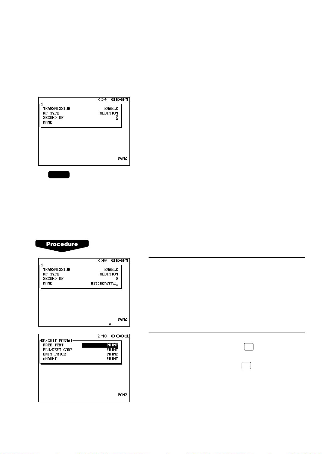
(5) Naming the remote printer – master and satellite
The programmed name will be printed, together with other data on the remote printer.
This enables exact identification of the printout if the remote printer fails.
After the KP SETTING window appears, proceed as follows:
1.
Move the cursor to the “NAME” line and enter a
desired name for the remote printer.
2.
To proceed to the step for programming for the remote
printer and chit format, press the key with the
cursor on the “NAME” line. To finish the programming
for the remote printer, press the key.
19
Page 21
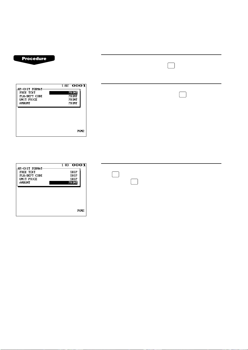
(6) Specifying the format of printing – master and satellite
ENTER
TL
•
ENTER
With the following procedure, you can specify what items to be printed on the remote printer
as well as on chits.
1.
Move the cursor to the last (“NAME”) line of the KP
setting window and press the key. The KP/CHIT
FORMAT window will open.
2.
Move the cursor to the following printing format items
and select PRINT or SKIP with the key (toggle
key).
Free text: PRINT/SKIP
PLU/department code: PRINT/SKIP
Unit price: PRINT/SKIP
Amount : PRINT/SKIP
The default setting of all items is SKIP.
3.
To finish the programming for the remote printer, press
the key with the KP/CHIT FORMAT window open,
or press the key with the cursor on the last
(“AMOUNT”) line.
20
Page 22
ENTER
ENTER
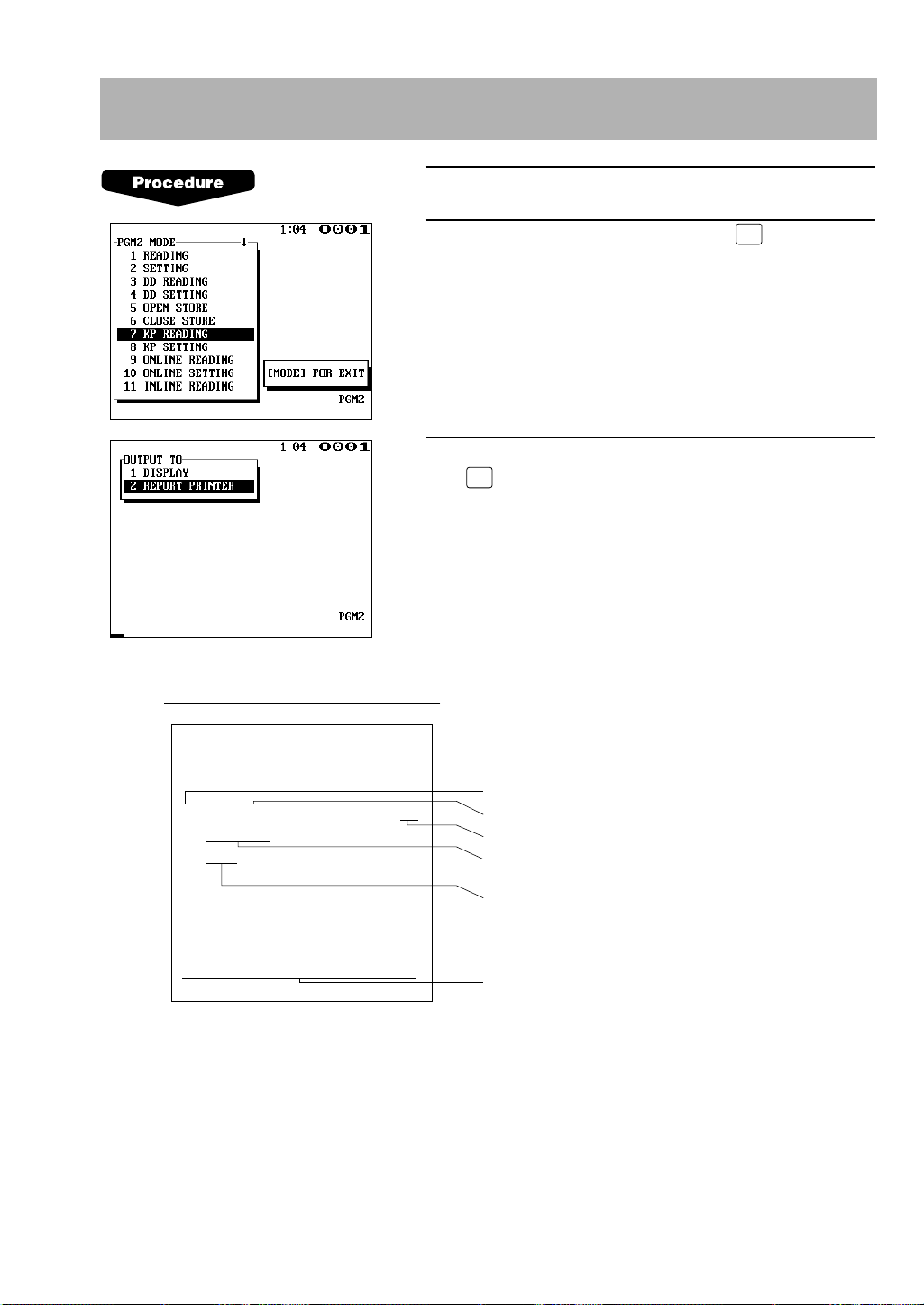
10. Reading the contents of the remote printer programming –
1 KI TCHEN PRT1
ADDI TION
KP–2
OK
6 KITCHEN PRT2
ADDI TION
KP–0
OK
KP/CHI T FOR
M
AT 1111
KP no.
Name of the remote printer
Data transmission: OK/NO
KP receipt type: ADDITION or
S/D (single/double) type
Second remote printer no.
KP/chit print format:
0 (print) or 1 (skip)
Sample Print (master)
∗PGM2∗
KP PRESE T
master and satellite
1.
Enter the PGM2 mode.
2.
Select “KP READING” and press the key.
3.
Select “DISPLAY” or “REPORT PRINTER” and press
the key.
21
Page 23
NOTE
ENTER
ENTER
ENTER
ENTER
11. Downloading the contents of the remote printer
programming to satellites – master
When you have completed the remote printer programming, distribute the preset data from the
master to all satellites in the IRC system.
1.
Enter the PGM2 mode.
2.
Select “INITIAL D/L” and press the key.
3.
The INITIAL D/L window will open. Select “KP
PRESET” and press the key.
4.
If you wish to download the KP PRESET data to all
satellites, select “ALL” and press the key. If you
wish to download the data to certain satellite(s), select
“MACHINE SELECT” and press the key. In this
case, the MACHINE SELECT window will open. Move
the cursor to the desired machine number and select
“YES”.
Check if all the satellites in the IRC system have received the preset data for the remote printer.
22
Page 24
ENTER
ENTER
ENTER
12.
Programming for the drink dispenser sales function (option)
(1) Choosing whether to set the local on-line or off-line mode for the drink
dispenser
If a trouble occurs in the IRC system, it is impossible to control the on-line/off-line mode
choice for a drink dispenser.
In this case, the on-line/off-line mode choice for the drink dispenser can be controlled not
through the IRC system but locally at each machine.
This local on-line/off-line mode choice is valid only for the drink dispenser whose number
was specified and distributed via the SRN. This job can only specify a drink dispenser
connected to another machine, while it cannot specify the drink dispenser directly connected
to the machine at which this programming is being carried out.
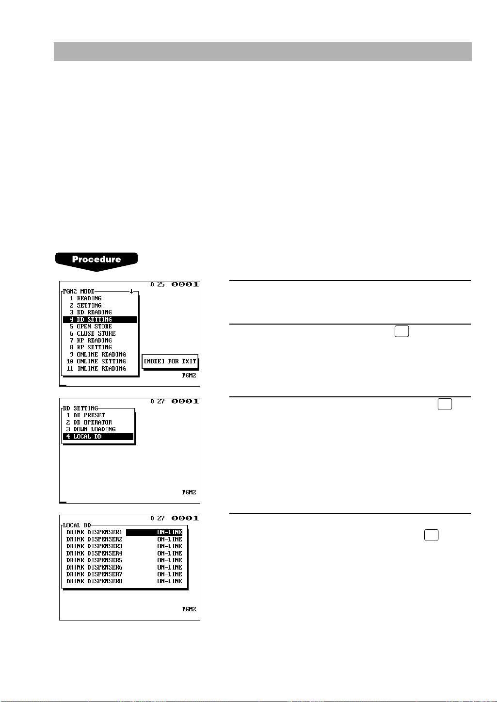
1.
Enter the PGM2 mode.
2.
Select “DD SETTING” and press the key.
3.
Move the cursor to “LOCAL DD” and press the
key.
4.
With the cursor at the desired drink dispenser number,
select ON-LINE or OFF-LINE and press the key.
23
Page 25

• This job directly changes the drink dispenser on-line/off-line mode information distributed, via
TL
TL
NOTE
the SRN, from another machine connected to a drink dispenser. When the SRN is recovered,
therefore, the on-line/off-line mode information on all machines in the system must be updated
again.
• This job does not check whether a drink dispenser with a specified number really exists or not.
(2) Notes on the programming for the drink dispenser(s) in the IRC system
1) Setting the link between sort codes and PLU codes in the IRC system
In the IRC system, the procedure for setting the link between sort codes and PLU codes is
the same as that in a standalone machine. (For the setting procedure, see the ER-A750
Instruction Manual.)
After the final key is pressed, the program for the drink dispenser sales article table is
sent to every machine in the IRC system. Thus the link information in the IRC system is
distributed in real time.
If the data cannot be sent to a machine, the corresponding machine number and error
message (“INLINE ERROR”) are shown on the display screen.
• Linking of the same PLU code is not disabled for sorting two or more drink dispensers in
the IRC system. In this case, however, the correction operation of the drink dispenser can
be executed at the machine to which the drink dispenser is not connected only when the
off-line mode is selected in all drink dispensers where this PLU code is linked.
2) Choosing whether to set the on-line or off-line mode for the drink dispenser
In the IRC system, the procedure for setting the on-line/off-line mode for the drink dispenser
is the same as that in a standalone machine. (For the setting procedure, see the Instruction
Manual of the ER-A750.)
After the final key is pressed, the drink dispenser on-line/off-line mode information is
sent to every machine in the IRC system. Thus the link information in the IRC system is
distributed in real-time.
If the data cannot be sent to a machine, the corresponding machine number and error
message (“INLINE ERROR”) are displayed.
24
Page 26

ENTER
ENTER
13. Reading the contents of the programming for the drink
dispenser sales function (PGM2 mode)
When the programming for a drink dispenser has been made, you can read the contents of the
programming using the appropriate job at the machine to which the drink dispenser is connected.
1.
Enter the PGM2 mode.
2.
Move the cursor to the “DD READING” line and press
the key.
3.
Select “DISPLAY” or “REPORT PRINTER” and press
the key.
25
Page 27

2
Inline Operation
1. Message display
(1) The message displayed during inline communication
1)The message shown below is displayed at the master engaged in IRC transmission
(broadcasting).
SENDING DATA
NOTE
The above message is also displayed at the satellite which is engaged in system resetting
transmission.
2)The machine number of the satellite that is communicating with the master is
instantaneously displayed at the master after the start of IRC transmission.
In this case, the machine number is “000022”.
000022
26
Page 28

(2) Error messages
CL
Error message (Default)
Description
ATTEMPT RETRY?
• This message prompts you to retry to communicate with a
machine when the communication does not end successfully.
• The target machine is busy.
• The specified clerk has signed on at another machine.
BUSY
CODE NOT FREE
• The entered GLU/PBLU code is in use.
•
IRC
clerk
sign-on error (when full
clerk
resetting executed).
• The GLU or drive-through code memory is full.
• SRN line error.
IS SIGNED ON
LACKING MEMORY
LINE ERROR
MOTOR LOCK
NO AUTHORITY
• The remote printer did not operate correctly.
• The clerk who entered a GLU/PBLU code was not authorized.
NO REPLY/BACKUP
• Back-up master doesn’t reply to the request.
OFF LINE
• Remote printer off-line error
POWER OFF
• The target machine is turned off.
SYSTEM OPENED
• Resetting executed in open store state (when inhibited only).
SYSTEM CLOSED
• Entry is executed in close store state.
T-LOG FULL
• The T-LOG file is full.
TYPE ERROR
• The file in the master and that in the satellite are not of the same type.
UNDEFINED CODE
• The specified clerk code is not present in the master list.
• The entered GLU/PBLU code is not listed.
NO REPLY/MASTER
• Master doesn’t reply to the request.
NON RESET
• IRC initial downloading before resetting
When an error occurs, a corresponding error message is displayed.
To clear an error, press the key. For error messages, see “List of error messages”.
List of error messages
27
Page 29

NOTE
ENTER
2. Open store operation (PGM2 mode) – master and satellite
When the open store operation is performed at the master, the IRC system is opened and the
registration function becomes available at all the machines in the IRC system. After this
operation, the following types of communications between the master and satellites are allowed.
From the master to the satellite
• Sending a request for the satellite to receive data (T-LOG polling)
• Sending a response to inquiry from the satellite
From the satellite to the master
• Sending data on the T-LOG buffer
• Sending a request for T-LOG polling
• Sending a request for updating of the GLU/PBLU file
• Inquiring for data on the GLU/PBLU
Open store procedure (PGM2 mode)
Select “OPEN STORE” from the PGM2 MODE window
and press the key.
• You can also perform the open store operation at each satellite. Once the open store operation
is performed at a satellite, you can make a registration at the satellite. With the open store
operation at satellites, T-LOG polling will not take place.
• The open store operation cannot be performed at any machines whose terminal numbers have
not been programmed.
• If a transmission error occurs when the open store operation is being performed, the master
displays and prints the machine number of the satellite that encountered the error. When the
master has been programmed to enable the system retry function*, retry the open store
operation.
* For the system retry function, see pages 64–65.
28
Page 30

NOTE
ENTER
3. Close store operation (PGM2 mode) – master and satellite
When the close store operation is performed at the master, the inline system is closed and the
registration function becomes unavailable at all the machines in the inline system. It should be
noted that for the close store operation, all the satellites must be in their SIGN-OFF state. After
this operation, the communications between the master and satellites which have been enabled
with the open store operation are disabled. The master, however, can download preset data and
reset the sales data at satellites.
In the close store state, any key operation in the REG or MGR mode is invalid.
Select “CLOSE STORE” from the PGM2 MODE window
and press the key.
• You can also perform the close store operation at each satellite. Once the close store
operation is performed at a satellite, you can no longer make a registration at the satellite.
• If a satellite is in the SIGN-ON state, the master encounters an error and prints the machine
number of the satellite.
• When the close store operation is performed, the data remaining in the T-LOG buffers of all the
satellites is collected by the master.
• If a transmission error occurs during the close store operation, the master displays and prints
the machine number of the satellite that has encountered the error.
In this case, a receipt is issued and the close store operation ends with an error.
29
Page 31

NOTE
ENTER
CLK
#
4. Sign-on operation (clerk assignment)
The sign-on operation is intended to assign a clerk to a machine (satellite or the master) and
enable him or her to perform entry operations at the machine.
If a clerk successfully signs on at a machine, his or her clerk code appears on the display of the
machine.
The clerk memory is under the control of the master.
The sign-on operation can be done whether the machine is in the open store or close store state.
If the sign-on operation is done at a machine that is in the close store state, however, any
registration cannot be made at the machine.
Sign-on procedure
(This procedure is the same as for clerk assignment at a standalone machine.)
• For the case of real clerk key system:
Insert a corresponding clerk key into the clerk switch.
• For the clerk entry key system:
Press a corresponding clerk entry key on the keyboard.
• For the WMF clerk key system:
Insert a corresponding WMF clerk key into the WMF clerk switch.
• For the code entry system:
Enter a corresponding clerk code and press the key.
The pop-up window for the secret code will open, if secret code is programmed. Enter a
secret code and press the key.
• The sign-on operation can be made only for one clerk at a time.
• If a clerk attempts to sign on when another clerk has already signed on, a lock error will occur.
• Every clerk that is listed in the system can sign on at any satellite.
• If a clerk has signed on at a machine, any other clerk cannot sign on at any other machine in
the system using the clerk code of that clerk until he or she signs off.
• In case of trouble, the sign-on state can be cleared at the master.
30
Page 32

NOTE
CLK
#
5. Sign-off operation (cancellation of clerk assignment)
The sign-off operation is intended to cancel the assignment of a clerk to a machine and
terminate his or her entry operation.
The sign-off operation at a machine (master or satellite) can be done only for the clerks who
have signed on at the machine.
Sign-off procedure
• For the real clerk key system:
Pull out the inserted clerk key.
• For the clerk entry key system:
Press the clerk entry key that you pressed to sign on, again.
• For the WMF clerk key system:
Pull out the inserted clerk key.
• For the clerk code entry system:
Press only the key.
• The sign-off operation can be made only for one clerk at a time.
• If a clerk signs on at a machine while another clerk has already signed on there, the latter is
automatically signed off.
31
Page 33

6. Clerk system
In the IRC system, the following two types of clerk file allocation systems are available: a
centralized system and an individual system. In the centralized file allocation system, the master
manages transaction data on clerks in the IRC system. In the individual file allocation system,
each machine manages clerk transaction data in it. For selection of the file allocation system,
contact your SHARP dealer.
(1) Centralized file allocation system
In this system, each clerk file is under the centralized control of the master and programming
for clerks has to be done only at the master. When a programmed clerk is signed on at a
satellite, a communication between the satellite and the master will begin. You can generate
a report which lists clerks signed on. (For further details on clerk sign-on reports, see the
next section.)
(2) Individual file allocation system
In this system, each clerk file is under the control of each satellite and you have to do
programming for clerks at each satellite. Even if a programmed clerk is signed on at a
satellite, a communication with the master will not begin. The data in the clerk file at each
satellite will be collected by the master when a consolidated report is issued.
(3) Notes on the IRC system that uses the overlapped clerk system
• If the overlapped clerk system is used, the clerk file must be allocated on the individual file
allocation system.
• When an initial entry is made at a satellite, additional entries and payment operation
cannot be made for the guest at the master or any other satellites in the IRC system.
32
Page 34

ENTER
ENTER
ENTER
ENTER
7. Clerk sign-on report
CLERK001 0001 000123
CLERK002 0002 000234
CLERK003 0003 000001
Sample Print (master)
NAME CODE M–No.
Clerk name, clerk code, machine no. of
the machine at which the clerk has signed on
∗PGM2∗
S I GN ON
A clerk sign-on report can be generated at the master. This report is used to know at which
satellite each clerk has signed on.
Report generation procedure
1.
Select “PGM2 MODE” from the mode selection
window and press the key.
2.
Select “INLINE READING” from the PGM2 MODE
window and press the key.
3.
Select “SIGN ON CLERK” from the INLINE READING
window and press the key.
4.
Select “DISPLAY” or “REPORT PRINTER” and press
the key.
33
Page 35

8. Look-up and updating of the GLU/PBLU file
In the IRC system, the GLU/PBLU file exists only in the master. All satellites in the IRC system
can access the GLU/PBLU file in the master for registration.
GLU/PBLU-file-related inline communications are made for the following purposes:
• New order or reorder
• Payment entry or temporary finalization
• Slip printing
• Bill transfer/bill totalizing
• Bill separating
There are two types of GLU/PBLU data transmission.
1) The GLU/PBLU data is transmitted from the master to a satellite for GLU/PBLU file look-up
(in case of a new order/reorder). In this case, the GLU/PBLU reserve counter* is retained at
the master.
* The reserve counter reserves some records of GLU/PBLU files to prevent a “LACKING MEMORY” error in
finalization.
2) The GLU/PBLU data is transmitted from a satellite to the master for finalization of a
transaction (in case of payment entry or temporary finalization).
The data transmitted from the satellite is once saved in the GLU/PBLU data receiving file and
then in the GLU/PBLU file. In this case, the GLU/PBLU reserve counter is cleared at the
master.
If a satellite looks up the GLU/PBLU file in the master or asks the master to update the file, the
backup master performs the same process as the master.
34
Page 36

9. Drive-through function
Depending on the setup of your system. Drive-through data is either centrally controlled by the
master or Individually looked up at each terminal. For more information, please contact your
authorized Sharp Dealer.
Automatic code generation
Drive-through codes are generated automatically: when the end code for a transaction is
generated, the start code for another transaction is automatically generated.
The start/end codes are programmable in the PGM mode.
Automatic look-up
As drive-through codes are temporarily finalized by pressing the or key, data for
these codes is automatically looked up in the same sequence as the code was generated.
Drive-through-related inline communications are made for the following purposes:
• New order or re-order
• Payment entry or temporary finalization
• Slip printing
• Bill transfer/bill totalizing
• Bill separating
FINALNBAL
The drive-through data is transmitted from the master to a satellite for drive-through file look-up
(in case of a new order/re-order). In this case, the drive-through reserve counter is retained at
the master.
The data is transmitted from a satellite to the master for finalization of a transaction (in case of a
payment entry or temporary finalization). The data transmitted from the satellite is once saved in
the drive-through data receiving file and then in the drive-through file. In this case, the drivethrough reserve counter is cleared at the master.
35
Page 37

10. T-LOG polling
Satellite BSatellite A Satellite C Satellite D
Master
(1) (2) (3)
(4)
(5) • • • • • •
All REG-mode transaction data in each satellite is saved in its T-LOG buffer. T-LOG polling is a
data collecting system in which the master collects data from the T-LOG buffers in satellites.
T-LOG polling becomes available upon open-store operation and becomes unavailable upon
close store operation.
A request for T-LOG polling is issued from the satellite to the master when the number of data
records in its T-LOG buffer exceeds a certain number in the open store state.
As the master detects such a request, it starts collecting T-LOG buffer data. After collecting of
data from one satellite, the master waits for a preset time and starts collecting data from another
satellite. In T-LOG polling, the data transmitted to the master is stored in the corresponding file.
The data flow in T-LOG polling is shown below.
Polling sequence (see the figure above)
(1) Satellite A makes a request for polling.
(2) The master detects the request and starts collecting T-LOG data from satellite A.
(3) The T-LOG data is sent to the master.
(4) After receiving T-LOG data from satellite A, the master waits for a preset time.
(5) The master detects a request from another satellite (B, C or D) and starts polling for it.
If its T-LOG buffer becomes full, any registration will be disallowed at a satellite when it has been
programmed for “LOCK UP”, and allowed when it has been programmed for “CONTINUE”. For
how to specify whether the registration is disabled or enabled when the T-LOG buffer becomes
full, see page 10.
36
Page 38

11. Communication with a remote printer (option)
When a remote printer is included in the inline system, order data is output to the remote printer
according to preset data on the remote printer.
The remote printer is used to print all or part of the data entered at a machine. It is also called a
kitchen printer. It can also be operated at a location other than the kitchen.
If a remote printer is assigned to a department or PLU, the information on the department or PLU
is output to the remote printer when or key is pressed or the transaction is finalized
at a machine.
The data which can be output to a remote printer is as follows:
1) Item text
2) Quantity*
3) Unit price*/Price*
4) Amount*
5) PLU/department code*
* Whether to print or not is selectable.
FINALNBAL
Second (back-up) remote printer
A second remote printer can be assigned to each remote printer for automatic back-up.
If an error occurs during data output to a remote printer, the data is output to the second remote
printer assigned to it.
If an error occurs during data output to the second remote printer, the data is output to the
receipt printer (the receipt printed at this printer is called a chit).
For how to specify the chit print format, see page 20.
Up to two remote printers can be preset to print data on each item (PLU or department).
If two printers are preset to print data on each item, the data is simultaneously output to both
printers.
If either of these printers encounters an error, the data is output to the backup printer.
If the second printer encounters an error, one receipt is printed.
37
Page 39

12. Rerouting receipt/journal print data
ER-A750
Print data (1)
Print data (1)
Print data (2)
ER-A750
ER-A750
via Sharp Retail Network
External printer
via RS-232 cable
External printer
Ordinary data flow
Rerouting data flow
One external printer connected by RS-232 cable can be shared by two or more ER-A750
machines. With this function every terminal does not need a receipt/journal printer.
Receipt/journal print data rerouting chart
38
Page 40

3
The system can generate two types of sales reports: consolidated reports (reports on all or
specified machines in the system) and individual reports (reports on an individual machine). At
the master, you can generate consolidated reports on all or specified satellites and reports on
the master itself. At each satellite, you can generate individual reports on that satellite.
Consolidated and Individual Reports
1. Operating modes
X1/Z1 mode: Daily sales reading (X1) and resetting (Z1) reports
X2/Z2 mode: Daily sales reading (X2) and resetting (Z1) reports and periodic consolidation
reading (X2) and resetting (Z2) reports
OPXZ mode: Individual clerk daily sales reading (X) and resetting (Z) reports
2. Job code
To generate a report in a short-cut way, enter an appropriate job code (four digits) (a two- or
three-digit number may be used since zero suppression is allowed) in the X1/Z1 or X2/Z2 mode
window and press the key (in case of the X1 or X2 report) or the key and the key
(in case of the Z1 or Z2 report).
Each job code is expressed as “XYnn” according to the table below.
Job code: XYnn
•
Entry Category of report
X
Y 1 Daily sales report (X1 or Z1)
nn Item code*
*An item code corresponds to the lower two digits of each job code listed in the tables on pages 41–43 and
45–47.
0 or 0 suppressed Individual report
1 Consolidated report
0 or 0 suppressed Clerk report in the OP X/Z mode
2 Periodic sales report (X2 or Z2)
39
Page 41

ENTER
ENTER
ENTER
ENTER
ENTER
ENTER
ENTER
3. Consolidated reports – master/back-up master
(1) Report generation procedure
To generate respective reports, use the following procedure, referring to the list of
consolidated reports on the following pages.
1.
Select the required operating mode (OPXZ, X1/Z1 or
X2/Z2) from the mode selection window and press the
key.
(If you select the X2/Z2 mode, the window for choice
between the X1/Z1 and X2/Z2 modes will open. Select
the required mode and press the key.)
2.
Select either SYSTEM READING or SYSTEM
RESETTING depending on your need, and press the
key.
40
3.
Select the type of report you wish to generate and
press the key. (If the desired type of report is not
listed on the display, scroll up or down the screen. )
4.
If you need to enter data to generate the report, follow
the instructions given on the display for entry.
5.
If you wish to generate the report of all the machines in
the system, select “ALL” and press the key. If you
wish to generate the reports of the specified machines,
select “MACHINE SELECT” and press the key. In
this case, the MACHINE SELECT window will open
Move the cursor to the machine number and select
“YES”.
6.
Select “DISPLAY” or “REPORT PRINTER” and press
the key.
Page 42

(2) List of consolidated reports (SYSTEM READING/RESETTING)
These reports can be printed on the printer unit (option) or shown on the display screen.
Report type Description
Operating mode
OPXZ
X1/Z1 X2/Z2
Job
code
Required data/Remarks
GENERAL Full item report — X1, Z1 X1, Z1 1100
— X2, Z2 1200
DEPT./GROUP
Individual
department report
— X1 X1 1110 Department code
— X2 1210
(The range can be specified by entering
start and end department codes.)
DEPT. IND GROUP Individual dept. — X1 X1 1112 Department group no.
group report — X2 1212 (1 to 17)
DEPT. GROUP Dept. group — X1 X1 1113
TOTAL total report — X2 1213
PLU BY RANGE PLU report by — X1, Z1 X1, Z1 1120 PLU code
specified range — X2, Z2 1220
(The range can be specified by
entering start and end PLU codes.)
PLU BY DEPT. PLU report by — X1, Z1 X1, Z1 1121 Department code
associated dept. — X2, Z2 1221
PLU IND. GROUP Individual group — X1 X1 1122 PLU group no. (0 to 99)
of PLU report — X2 1222
PLU GROUP TOTAL PLU group total — X1 X1 1123
report — X2 1223
PLU STOCK PLU stock report — X1 X1 1124 PLU code
(The range can be specified by
entering start and end PLU codes.)
PLU COST PLU cost report — X1 X1 1125 PLU code
PLU TOP 20
PLU top-20 report
— X2 1225
— X1 X1 1126 Amount or quantity can be
(The range can be specified by
entering start and end PLU codes.)
— X2 1226 selected.
PLU ZERO SALES PLU zero sales — X1 X1 1127 All PLUs of zero sales
report — X2 1227
PLU ZERO SALES
BY DEPT.
PLU zero sales report
— X1 X1 1127 Department code
by specified dept.
— X2 1227
41
Page 43

Report type Description
Operating mode
OPXZ X1/Z1 X2/Z2
Job
code
Required data/Remarks
PLU MIN. STOCK PLU minimum — X1 X1 1128 PLU code
PLU HOURLY
GROUP
TRANSACTION
stock report
PLU hourly group
report
Transaction report
— X1, Z1 X1, Z1 1129 Time
— X1 X1 1130
(The range can be specified by
entering start and end PLU codes.)
(The range can be specified by
entering start and end codes.)
— X2 1230
TL-ID
Total-in-drawer report
— X1 X1 1131
COMMISSION Commission — X1 X1 1132
SALES sales report — X2 1232
TAX Tax report — X1 X1 1133
— X2 1233
CHIEF Chief sales — X1 X1 1134
report
ALL CLERK Full clerk report — X1, Z1 X1, Z1 1140 For all clerks
— X2, Z2 1240
IND. CLERK Individual clerk X, Z — — 1041
report — X1, Z1 X1, Z1 1141
— X2, Z2 1241
DD ERROR Drink dispenser X1, Z1 X1, Z1 1143
error reading
DD RESET Drink dispenser Z1 Z1 1179
resetting
EMPLOYEE Employee report — — X2, Z2 1255 Employee code
(The range can be specified by
entering start and end codes.)
EMP. ADJUSTMENT
Employee — — X2 1256 Employee code
adjustment report
(The range can be specified by
entering start and end codes.)
42
Page 44

Report type Description
Operating mode
OPXZ X1/Z1 X2/Z2
Job
code
Required data/Remarks
EMP. ACTIVE STS. Employee active — — X2 1257 Employee code
status report
(The range can be specified by
entering start and end codes.)
HOURLY Hourly report — X1 X1 1160 For an individual time range
(by specified range)
Hourly report (all) — X1, Z1 X1, Z1 1160 For all 48 half-hours with
zero skipped
LABOR COST %
Labor cost
— X1 X1 1161
percentage report
DAILY NET Daily net report — — X2, Z2 1270
INGREDIENT Ingredient — X1 X1 1175 Ingredient no.
STOCK stock report
GLU GLU report — X1, Z1 X1, Z1 1180 GLU code
(The range can be specified by
entering start and end codes.)
GLU BY CLERK
GLU report by clerk
— X1, Z1 X1, Z1 1181
DRIVE THRU Drive-through — X1, Z1 X1, Z1 1185 Drive-through code
report
(The range can be specified by
entering start and end codes.)
D-THRU BY CLERK Drive-through — X1, Z1 X1, Z1 1186
report by clerk
BALANCE Balance report X1 X1 1101
— X2 1201
STACKED REPORT Stacked report — X1, Z1 X1, Z1 1190 Stacked report 1
(X1, Z1) 1191 Stacked report 2
STACKED REPORT Stacked report — X2, Z2 1290 Stacked report 1
(X2, Z2) 1291 Stacked report 2
43
Page 45

ENTER
ENTER
ENTER
ENTER
ENTER
4. Individual report – master/back-up master/satellite
(1) Report generation procedure
To generate respective reports, use the following procedure, referring to the list of individual
reports on the following pages.
1.
Select the required operating mode (OPXZ, X1/Z1 or
X2/Z2) from the mode selection window and press the
key.
(If you select the X2/Z2 mode, the window for choice
between the X1/Z1 and X2/Z2 modes will open. Select
the required mode and press the key.)
2.
Select either READING or RESETTING depending on
your need, and press the key.
3.
Select the type of report you wish to generate and
press the key. (If the desired type of report is not
listed on the display, scroll up or down the screen. )
4.
If you need to enter data to generate the report, follow
the instructions given on the display for entry.
5.
Select “DISPLAY” or “REPORT PRINTER” and press
the key.
44
Page 46

(2) List of individual reports (READING/RESETTING)
These reports can be printed on the printer unit (option) or shown on the display screen.
Report type Description
Operating mode
OPXZ X1/Z1 X2/Z2
Job
code
Required data/Remarks
GENERAL Full item report — X1, Z1 X1, Z1 100
— X2, Z2 200
DEPT./GROUP Full department — X1 X1 110 Department code
report — X2 210
(The range can be specified by entering
start and end department codes.)
DEPT. IND. GROUP Individual dept. — X1 X1 112 Department group no.
group report — X2 212 (1 to 17)
DEPT. GROUP Dept. group total — X1 X1 113
TOTAL report — X2 213
PLU BY RANGE PLU report by — X1, Z1 X1, Z1 120 PLU code
specified range — X2, Z2 220
(The range can be specified by
entering start and end PLU codes.)
PLU BY DEPT. PLU report by — X1, Z1 X1, Z1 121 Department code
associated dept. — X2, Z2 221
PLU IND. Individual group — X1 X1 122 PLU group no. (0 to 99)
GROUP report of PLU — X2 222
PLU GROUP PLU group total — X1 X1 123
TOTAL report — X2 223
PLU STOCK PLU stock report — X1 X1 124 PLU code
(The range can be specified by
entering start and end PLU nos.)
PLU COST PLU cost report — X1 X1 125 PLU code
PLU TOP 20
PLU top-20 report
— X2 225
— X1 X1 126 Amount or quantity can be
(The range can be specified by
entering start and end PLU nos.)
— X2 226 selected.
PLU ZERO SALES PLU zero sales — X1 X1 127 All PLUs of zero sales
report — X2 227
PLU ZERO SALES
BY DEPT.
PLU zero sales report
by specified dept.
— X1 X1 127 Department code
— X2 227
PLU MIN. STOCK PLU minimum — X1 X1 128
stock report
45
Page 47

Report type Description
Operating mode
OPXZ X1/Z1 X2/Z2
Job
code
Required data/Remarks
PLU HOURLY Hourly PLU — X1, Z1 X1, Z1 129
GROUP group report
TRANSACTION Transaction — X1 X1 130
report — X2 230
TL-ID Total-in-drawer — X1 X1 131
report
COMMISSION Commission — X1 X1 132
SALES sales report — X2 232
TAX Tax report — X1 X1 133
— X2 233
CHIEF Chief sales — X1 X1 134
report
ALL CLERK Full clerk report — X1, Z1 X1, Z1 140 For all clerks
— X2, Z2 240
IND. CLERK Individual clerk X, Z — — 41
report — X1, Z1 X1, Z1 141
— X2, Z2 241
DD ERROR Drink dispenser X1, Z1 X1, Z1 1143
error reading
DD RESET Drink dispenser Z1 Z2 1179
resetting
EMPLOYEE Individual — — X2, Z2 255 Employee code
employee
report
(The range can be specified by
entering start and end codes.)
EMP. ADJUSTMENT Employee — — X2 256 Employee code
adjustment
report
(The range can be specified by
entering start and end codes.)
EMP. ACTIVE STS. Employee active — — X2 257 Employee code
status report
(The range can be specified by
entering start and end codes.
)
46
Page 48

Report type Description
Operating mode
OPXZ X1/Z1 X2/Z2
Job
code
Required data/Remarks
HOURLY Hourly report — X1 X1 160 For an individual time range
(by specified range)
LABOR COST %
Hourly report (all)
Labor cost
— X1, Z1 X1, Z1 160 For all 48 half-hours with
zero skipped
— Z1 Z1 161
percentage report
DAILY NET Daily net report — — X2, Z2 270
INGREDIENT Ingredient stock — X1 X1 175 Ingredient no.
STOCK report
GLU GLU report — X1, Z1 X1, Z1 180 GLU code
(
The range can be specified by
entering start and end codes.)
GLU BY CLERK GLU report by — X1, Z1 X1, Z1 181
clerk
DRIVE THRU Drive-through — X1, Z1 X1, Z1 185 Drive-through code
report (
The range can be specified by
entering start and end codes.)
D-THRU BY CLERK Drive-through — X1, Z1 X1, Z1 186
report by clerk
BALANCE Balance report — X1 X1 101
— X2 201
STACKED Stacked report — X1, Z1 X1, Z1 190 Stacked report 1
REPORT (X1/Z1) 191 Stacked report 2
STACKED Stacked report — X2, Z2 290 Stacked report 1
REPORT (X2/Z2) 291 Stacked report 2
47
Page 49

NOTE
5. Clerk report
01 / 05 / 96
#0123 12: 34
123456
M
EYER0001
#1140 ∗
Z1
∗
CLERK STOP
CLERK START
ALL CLERK
CLK#
00 01
ORDER TL
CLERK Z1
CLERK001
0001
∗115 .25
000002 IS S IGNED ON
CLK#
0002
ORDER TL
CLERK002
∗123 .75
Date
Machine number
Consecutive number
Time
Clerk name and code
Job code
Report mode
Report type
Data on clerk #0002
Reset counter
Clerk name
Data on clerk #0001
The symbol of the clerk (#0002) who is
signed on at machine no. 000002.
Sample Print (master)
As stated earlier (see page 32), there are two systems for collecting clerk sales data: a
centralized file allocation system and an individual file allocation system.
(1) Centralized file allocation system
In this system, the transaction data on a clerk in each satellite will be transmitted to the
master each time the clerk is signed off. You cannot generate an individual clerk report for
each satellite. At the master, you can generate all and individual clerk consolidation reports.
At each satellite, you can generate individual clerk consolidation reports.
If a clerk is signed on at a satellite where resetting operation for a consolidated individual
clerk Z report is generated, the data on transactions made by him or her is also added to the
report and printed out. (If that clerk is signed on at another machine, the message “SIGN
ON” is printed and resetting operation for this clerk cannot be made.)
All clerk report sample in the centralized file allocation system
For the detailed information on report items, see the ER-A750 Instruction Manual.
48
Page 50

(2) Individual file allocation system
NOTE
01 / 05 / 97
#0123 12: 34
123456
M
EYER0001
#0140 ∗
Z1
∗
ALL CLERK
CLK#
00 01
ORDER TL
CLERK Z1
CLERK001
0001
∗115 .25
CO
M
.SAL1 ∗15.50
CHK/ CG
∗
COPY
∗
∗
COPY
∗
∗6 .80
CLK#
0002
ORDER TL
Symbol of copy
CO
M
.SAL1
CHK/CG
CLERK002
∗563.93
∗23.50
∗38.20
In this system, you can generate full or individual clerk consolidation Z reports at the master
only. At each machine, you can generate a X or Z report on transactions made by an
individual clerk or clerks assigned to the machine.
If the system has no save file, the clerk for whom a Z report has been generated is not
allowed to make entries in the REG mode. This condition, in which entries by the clerk are
disallowed, is canceled when his or her sales data is consolidated and reset at the master or
when the sales data is manually cleared. (For the manual clearing operation, see pages
52–53.)
When a Z report for the locked clerk is generated again, the COPY mark will be printed in
the report as shown below. (This COPY mark will not appear when the system has a save
file.)
A full clerk report in the individual file allocation system
For selecting whether your system should have a save file or not, consult your SHARP dealer.
49
Page 51

6. Reports that can be generated when the Compulsory
Cash/Cheque Declaration (CCD) function is enabled
Each machine can be programmed to enable the Compulsory Cash/Cheque Declaration function
which compels the operator to enter the cash/cheque amount in the drawer just before either an
individual clerk Z report or a full clerk Z report is printed. If a machine is equipped with this
function, you cannot generate some reports as shown below. (For further details on this function,
see the ER-A750 Instruction Manual. )
(1) When the individual clerk file allocation system is selected:
List of consolidated reports
Compulsory before Compulsory before
CCD entry Non-compulsory generating individual generating full clerk
Z reports Z reports
Type of report
Individual clerk 1Y41 O O ✕ O* ✕ ✕
Full clerk 1Y40 O O O* O* ✕ O*
Other consolidated reports
Job code
X Z X Z X Z
O O O* O* O* O*
✕: Report generation is not allowed.
O: Report generation is allowed.
* : If the CCD entry was not executed at the satellite, report generation is not allowed there and
the message “RETRY?” will appear (if at the master, “LOCK ERROR” will appear).
List of individual reports
Compulsory before Compulsory before
CCD entry Non-compulsory generating individual generating full clerk
Z reports Z reports
Type of report
Individual clerk 1Y41 O O ✕ ✩ ✕ ✕
Full clerk 1Y40 O O O* O* ✕ ✩
Other individual report O O O* O* O* O*
✕: Report generation is not allowed.
O: Report generation is allowed.
✩: CCD reports can be generated.
* : If the CCD entry was not executed at the satellite, report generation is not allowed there and
the message “RETRY?” will appear (if at the master, “LOCK ERROR” will appear).
Job code
X Z X Z X Z
50
Page 52

(2) When the centralized clerk file allocation system is selected:
(Same as the standalone machine)
Compulsory before Compulsory before
CCD entry Non-compulsory generating individual generating full clerk
Z reports Z reports
Type of report
Individual clerk 1Y41 O O ✕ ✩ ✕ ✕
Full clerk 1Y40 O O ✕ ✕ ✕ ✩
Other individual report O O ✕ ✕ ✕ ✕
✕: Report generation is not allowed.
O: Report generation is allowed.
✩: CCD reports can be generated.
Job code
X Z X Z X Z
51
Page 53

ENTER
ENTER
ENTER
ENTER
7. Reset clear operation (X1/Z1 and X2/Z2 modes) — master
Even when a machine has been programmed to disallow entries after full item total resetting or
not programmed for automatic reset clearing upon open store operation, you can unlock the
machine after full item daily total resetting in order to restart entries.
Examples Reset clearing procedure
In the case of X1/Z1
1.
Enter the X1/Z1 mode from the mode selection
window.
2.
Select “RESET CLEAR” and press the key.
52
3.
If you wish to clear the lock state of all the machines in
the system, select “ALL” and press the key. If you
wish to clear the lock state of the specified machines,
select “MACHINE SELECT” and press the key. In
this case, the MACHINE SELECT window will open.
Move the cursor to the machine number and select
“YES”.
4.
Select “DISPLAY” or “REPORT PRINTER” and press
the key.
Page 54

In the case of X2/Z2
ENTER
ENTER
ENTER
ENTER
ENTER
1.
2.
3.
Enter the X2/Z2 mode from the mode selection
window.
The window for choice between the X1/Z1 and X2/Z2
modes will open. Select the X2/Z2 mode and press the
key.
Select “RESET CLEAR” and press the key.
4.
If you wish to clear the lock state of all the machines in
the system, select “ALL” and press the key. If you
wish to clear the lock state of the specified machines,
select “MACHINE SELECT” and press the key. In
this case, the MACHINE SELECT window will open.
Move the cursor to the machine number and select
“YES”.
5.
Select “DISPLAY” or “REPORT PRINTER” and press
the key.
53
Page 55

4
System Back-Up
1. How the IRC back-up system works
The IRC system incorporates a back-up system.
One of the satellites can be designated to serve as a back-up master.
When both the master and back-up master are in order, the system works in the following
sequence:
(1)Each satellite sends updated GLU/PBLU data to the master.
(2)The master receives the data, processes it and sends it back to the satellite.
(3)The satellite sends the updated data to the back-up master.
(4)The back-up master receives the data, processes it and sends it back to the satellite.
Master
(Processi ng)
(1) Updated data (3) Updated data
(2) Processed data
Satelli te
If the master breaks down, the back-up master serves as the master after a master declaration is
made at the back-up master. If the back-up master breaks down, updated data transmission to it
can be stopped by a master declaration at the master. When the master or back-up master
recovers from the breakdown, it resumes its function as the master or back-up master by the
recovery declaring operation.
(4) Processed data
Back-up master
(Processi ng)
54
Page 56

2. Master declaration
— when the master or back-up master breaks down
When the master or back-up master breaks down, the master declaration procedure should be
taken to inform satellites of the breakdown.
(1) When the master breaks down — Master declaration at the back-up
master
1) A satellite detects a breakdown of the master through the system retry function when it is
sending updated GLU/PBLU data to the master. At this point, the message “MASTER
DOWN” appears in the pop-up window of the display.
MASTER DOWN
*For the system retry function, see pages 64–65.
2) The master declaration operation must be done at the back-up master. This operation
informs the other satellites that the master has broken down and the back-up master will
serve as the master hereafter. (During this process, no other operation cannot be done at
each satellite.)
3) Each satellite in the IRC system starts sending updated GLU/PBLU data to the back-up
master.
4) The back-up master processes the received data and sends back the processed data to
each satellite.
Flow of a master declaration at the back-up master
Master
1) Detection of a breakdown
(Transmission stops.)
2) Master
declaration
Satellite
3) Updated data
4) Processed data
Master declaration
Back-up master
(Processing)
55
Page 57

The master declaration procedure is as follows:
ENTER
ENTER
ENTER
1.
Select “PGM2 MODE” from the mode selection
window and press the key.
2.
Select “DECLARATION” and press the key.
3.
Select “MASTER DECLARE” and press the key.
56
Page 58

(2) When the back-up master breaks down — Master declaration at the
1) Detection of a master breakdown
3) Updated data
Satellite
(Processing)
4) Processed data
(Transmission stops.)
Back-up master
Master
2) Master declaration
master
1) A satellite detects a breakdown of the back-up master through the system retry function
when it is sending updated GLU/PBLU data to both the master and back-up master. At
this point, the message “BMA DOWN” appears in the pop-up window of the display.
BMA DOWN
2) The master declaration operation must be done at the master. This operation causes
each master to inform all satellites of the breakdown of the back-up master.
3) Each satellite in the IRC system sends updated GLU/PBLU data only to the master.
4) The master processes the received data and sends back the processed data to each
satellite.
Flow of a master declaration at the master
The master declaration procedure is the same as “(1) When the master breaks down.”
57
Page 59

3. Recovery declaration — when the master
3) Updated data file
Satellite
(Processing)
4) Master
recovery
information
2) Transmission stops.
Master declaration
1) Recovery
declaration
operation
Back-up master
Master
5) Restart of updated
data transmission
or back-up master recovers from a breakdown
When the master or back-up master recovers from a breakdown, the recovery declaration
operation should be taken to inform satellites of the recovery.
(1) When the master recovers from a breakdown — Recovery declaration at
the back-up master
1) The recovery declaration operation is done at the back-up master.
2) Each satellite stops sending updated GLU/PBLU data to the back-up master.
3) The back-up master sends the updated GLU/PBLU data files to the master.
4) The back-up master informs all satellites of the master’s recovery.
5) The satellites restart sending updated GLU/PBLU data to the master.
Flow of a recovery declaration at the back-up master
58
Page 60

The recovery declaration procedure is as follows:
ENTER
ENTER
ENTER
1.
Select “PGM2 MODE” from the mode selection
window and press the key.
2.
Select “DECLARATION” and press the key.
3.
Select “RECOVER DECLARE” and press the key.
59
Page 61

(2) When the back-up master recovers from a breakdown — Recovery
2) Transmission stops
temporarily.
3) Updated data file
Satellite
4) Back-up master
recovery information
Back-up master
Master
1) Recovery declaration
5) Restart of updated data transmission
(Processing)
declaration at the master
1) The recovery declaration operation is done at the master.
2) Each satellite stops sending updated GLU/PBLU data to the master temporarily.
3) The master sends the updated GLU/PBLU data files to the back-up master.
4) The master informs all satellites of the back-up master’s recovery.
5) The satellites restart sending updated GLU/PBLU data to the back-up master.
Flow of a recovery declaration at the master
The recovery declaration procedure is the same as “(1) When the master recovers from a
breakdown.”
60
Page 62

5
Error Recovery
1. Manual clear operation
With the manual clear operation, you can clear various item memories when necessary. This
operation should be done only when the master or system breaks down.
(1) Manual clearing of the sign-on state — master
You can clear the sign-on state in case of trouble.
This operation is effective only for the sign-on flag for clerks who are signed on at the
master.
Clearing procedure
1.
Select “PGM2 MODE” from the mode selection
window and press the key.
ENTER
2.
Select “MANUAL CLEAR” and press the key.
3.
Select “SIGN ON FLAG” and press the key.
NOTE
Clerk sales data for each satellite at which a clerk has signed on is not collected by manual
clearing of the sign-on state. Clerk sales data is collected only when sign-off operation is
done correctly at satellites.
ENTER
ENTER
61
Page 63

(2) Manual clearing of the GLU/PBLU data in use — master
You can clear the GLU/PBLU data in use in the event of some trouble.
This operation clears all GLU/PBLU data that is currently in use.
Clearing procedure
After selecting “MANUAL CLEAR” from the PGM2 MODE window with the same procedure
as steps 1 and 2 in “(1) Manual clearing of the sign-on state”, select “GLU USED FLAG”.
(3) Manual clearing of the drive-through data in use — master
You can clear the drive-through data in use in the event of some trouble.
This operation clears all drive-through data that is currently in use.
Clearing procedure
After selecting “MANUAL CLEAR” from the PGM2 MODE window with the same procedure
as steps 1 and 2 in “(1) Manual clearing of the sign-on state”, select “DRIVE THRU FLAG”.
(4) Manual clearing of the department/transaction memory — master and
satellite
You can clear the department/transaction memory in the event of some trouble.
This function is available at the master and satellites.
Clearing procedure
After selecting “MANUAL CLEAR” from the PGM2 MODE window with the same procedure
as steps 1 and 2 in “(1) Manual clearing of the sign-on state”, select “DEPT/TRANS.”.
(5) Manual clearing of the clerk sales data memory — master and satellite
You can clear the clerk sales data memory in the event of some trouble. This function is
available at the master and satellites.
Clearing procedure
After selecting “MANUAL CLEAR” from the PGM2 MODE window with the same procedure
as steps 1 and 2 in “(1) Manual clearing of the sign-on state”, select “CLERK”.
62
Page 64

(6) Manual clearing of the hourly sales data memory — master and satellite
NOTE
You can clear the hourly sales data memory in the event of some trouble. This function is
available at the master and satellites.
Clearing procedure
After selecting “MANUAL CLEAR” from the PGM2 MODE window with the same procedure
as steps 1 and 2 in “(1) Manual clearing of the sign-on state”, select “HOURLY”.
(7) Manual clearing of the daily net sales data memory — master and
satellite
You can clear the daily net sales data memory in the event of some trouble. This function is
available at the master and satellites.
Clearing procedure
After selecting “MANUAL CLEAR” from the PGM2 MODE window with the same procedure
as steps 1 and 2 in “(1) Manual clearing of the sign-on state”, select “DAILY NET”.
(8) Manual clearing of the T-LOG buffer — master and satellite
You can clear the T-LOG buffer in the event of some trouble. This function is available at the
master and satellites.
Clearing procedure
After selecting “MANUAL CLEAR” from the PGM2 MODE window with the same procedure
as steps 1 and 2 in “(1) Manual clearing of the sign-on state”, select “T-LOG BUFFER”.
• For T-LOG polling, see page 36.
• The above-mentioned manual clearing jobs should be performed at the advice of your
authorized Sharp dealer.
63
Page 65

2. System retry function
If a satellite terminates a transmission job unsuccessfully, the master either terminates the job
immediately or awaits a command given through the keyboard or by menu option selection,
depending on whether the system retry function is disabled or enabled. When the system retry
function is enabled, the master awaits the entry of a command and retries access depending on
the command as explained below.
This function is used in the following cases:
• The master has failed to download preset or updated data to all or some of the satellites.
• The master has failed to upload sales reports from all or some of the satellites.
• The satellite has failed to download data to other machines.
Whether the system retry function is enabled or disabled when a transmission error occurs is
programmed at the master (See “5. Specifying whether to enable or disable the system retry
function when a transmission error occurs” on page 9.)
(1) When the system retry function is disabled:
The master terminates the transmission job immediately in the following two ways.
If none of the satellites have successfully transmitted data, the transmission is regarded as
having ended with an error, which is equivalent to ABORT as discussed below.
If there is any satellite which has successfully transmitted data, the transmission is regarded
as either successful or unsuccessful depending on the type of transmission job. In this case,
the transmission regarded as successful and the one regarded as unsuccessful are
equivalent to IGNORE and ABORT, respectively, both of which are explained below.
(2) When the system retry function is enabled:
If a transmission error occurs, the number and error state of the satellite in which the error
has occurred and the relevant menu will appear on the display and the master awaits the
entry of one of the following commands given by menu option selection or through the
keyboard:
A) RETRY command (selection from the menu or press of the 1 key)
B) ABORT command (selection from the menu or press of the 2 key)*
C) IGNORE command (selection from the menu or press of the 3 key)
(* If there are only RETRY and IGNORE on the menu, press the 2 key.)
A) RETRY command:
When RETRY is selected, the master attempts a RETRY to the satellite; however, it does not
retry when, due to the type of error (for example, command error), it is obvious that the
RETRY will fail. This means that the master will not gain access if errors that have occurred
during transmission are such types of errors.
64
Page 66

B) ABORT command
When ABORT is selected, the master terminates access to the satellite and regards the
transmission as having unsuccessfully ended. However, in the case of program data
downloading, the ABORT command may be issued only when all the satellites accessed are
in the error state.
C) IGNORE command
When IGNORE is selected, the master terminates access to the satellite, regards the
transmission as having successfully ended and prints only transmitted data.
If no satellites have successfully transmitted data, the IGNORE command may be issued to
the master in the case of sales data inquiry (X report), though the result is not printed.
[Retry during sales data inquiry]
During resetting, the ABORT command may be given only when every accessed satellite is
in the error state. The IGNORE and RETRY commands are available unconditionally.
65
Page 67

Basic Specifications
Transmission system: Serial synchronous, half-duplex transmission.
Transmission line: Common bus system
Transmission speed: 1 Mbits/sec
Transmission distance: Total (main + branch) max. 1 km
Transmission cable: Coaxial cable RG-58/U
No. of connectable machines: Master: 1
Satellites/remote printers: max. 15
(Remote printers alone: max. 9)
Transfer system: Packet-unit
66
Page 68

6
•ER-03RP
Physical characteristics
Handling the Remote Printer
Online switch
Line feed switch
Control panel
Paper outlet
Ribbon cover
Connector
AC power receptacle
Paper cover
Power switch
67
Page 69

1. Lamps and switches
(1) Lamps
• Power lamp
This lamp lights up when the power switch of the remote printer is turned on.
• Online lamp
This lamp lights up when the online switch is pressed, and goes off when the switch is
pressed again.
• Alarm lamp
This lamp lights up when the remote printer malfunctions. In this case the printer neither
prints any data nor feeds the paper. The alarm state can be cleared by pressing the ON
LINE switch or by setting the power switch to the OFF position and then back to the ON
position.
(2) Switches
• Power switch
This switch is used to energize the remote printer.
• Online switch
This switch is used to make the remote printer perform printing.
It must be pressed before starting registrations which require printing.
• Line feed switch
This switch is used to advance the paper in the remote printer.
2. Replacement of the paper roll
When a colored dye appears on the paper roll, it means that it is time to replace the existing
paper roll. Replace the paper roll with a new one by using the procedures described below.
When installing a paper roll for the first time, take steps 1 and 4 through 7.
1.
Pull up the paper cover and remove it.
68
Page 70

2.
NOTE
Cut the paper along the broken line.
3.
Press the line feed switch to remove the paper
remaining in the printer.
3 to 5 cm
How to fold paper
4.
Fold the top end of the paper roll by 3 to 5 cm securely
as shown at left.
5.
Insert the end of the folded paper deep into the paper
chute of the printer and press the line feed switch to
advance the paper.
If paper is not inserted deep enough, it will not
advance when the line feed switch is pressed.
6.
Take up the slack in the paper and set the roll in
position.
7.
Pass the top end of the paper through the paper cutter
on the paper cover and close it.
69
Page 71

3. Replacement of the ink ribbon cassette
When the print becomes faint, replace the ink ribbon cassette with a new one according to the
procedures described below.
Be sure to turn off the remote printer before replacing the ink ribbon cassette.
1.
Pull up the ribbon cover and remove it.
2.
Rotate the take-up knob of the ink ribbon cassette in
the direction of the arrow to tighten the ink ribbon.
Ink ribbon
cassete
Ink ribbon
Take-up knob
3.
Push the ink ribbon cassette to the left, then lift up its
right side to remove it.
4.
Rotate the take-up knob of the new ink ribbon cassette
to tighten the ink ribbon. Install the new ink ribbon
cassette so that the ink ribbon gets into the gap shown
at left.
5.
Close the ribbon cover.
70
Page 72

• ER-04RP
Physical characteristics
Online switch
Line feed switch
Control panel
Paper outlet
Ribbon cover
Paper cover
Connector
AC power receptacle
Power switch
71
Page 73

1. Lamps and switches
(1) Lamps
• Power lamp
This lamp lights up when the power switch of the remote printer is turned on.
* Online lamp
This lamp lights up when the online switch is pressed, and goes off when the switch is
pressed again.
• Alarm lamp
This lamp lights up when the remote printer malfunctions. In this case the printer neither
prints any data nor feeds the paper. The alarm state can be cleared by pressing the
online switch or by setting the power switch to the OFF position and then back to the ON
position.
(2) Switches
• Power switch
This switch is used to energize the remote printer.
• Online switch
This switch is used to make the remote printer perform printing.
It must be pressed before starting registrations which require printing.
• Line feed switch
This switch is used to advance the paper in the remote printer.
2. Replacement of the paper roll
When a colored dye appears on the paper roll, it means that it is time to replace the existing
paper roll. Replace the paper roll with a new one according to the procedures described below.
When installing a paper roll for the first time, take steps 1 and 4 through 7.
1.
Pull up the paper cover and remove it.
72
Page 74

NOTE
3 to 5 cm
How to fold paper
2.
Cut the paper along the broken line.
3.
Press the line feed switch to remove the paper
remaining in the printer.
4.
Fold the top end of the paper roll by 3 to 5 cm securely
as shown at left.
5.
Insert the end of the folded paper deep into the paper
chute of the printer and press the line feed switch to
advance the paper.
If paper is not inserted deep enough, it will not
advance when the line feed switch is pressed.
6.
Take up the slack in the paper and set the roll in
position.
7.
Close the paper cover.
73
Page 75

3. Replacement of the ink ribbon cassette
When the print becomes faint, replace the ink ribbon cassette with a new one according to the
procedures described below.
Be sure to turn off the remote printer before replacing the ink ribbon cassette.
1.
Remove the paper cover and the ribbon cover.
2.
Pulling the release levers, lift up the auto cutter.
74
Ink ribbon
cassete
Take-up knob
3.
Rotate the take-up knob of the ink ribbon cassette in
the direction of the arrow to tighten the ink ribbon.
4.
Push the ink ribbon cassette to the left, then lift up its
right side to remove it.
Page 76

Ink ribbon
5.
Rotate the take-up knob of the new ink ribbon cassette
to tighten the ink ribbon. Install the new ink ribbon
cassette so that the ink ribbon gets into the gap shown
at left.
6.
Release the auto cutter and close the ribbon cover and
the paper cover.
75
Page 77

SHARP CORPORATION
Printed in Korea / Imprimé en Corée / Gedruckt in Korea / Impreso en Corea
Oi
TINSE7377BHZA
j@
 Loading...