

Page 1
Dealer Knowledge Book
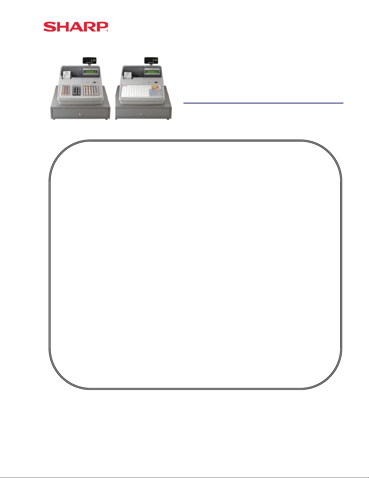
ER-A520 ER-A530
MODEL ER-A520 & ER-A530
Dealer Knowledge Book
Contents
Category
SECTION 1. System Presets
SECTION 2. Free Key Layouts
SECTION 3. File Allocation
SECTION 4. Peripherals
SECTION 5. PGM2 Mode Programming
Departments……………………………………………………………………………………………….
PLU/UPC…………………………………………………………………………………………………...
Cashiers……………………………………………………………………………………………………
Function & Media Keys…………………………………………………………………………………..
Machine Settings……………………………………………………………………………………….....
SECTION 6. COM Communication
SECTION 7. Electronic Funds Transfer
SECTION 8. Utilities
SECTION 9. SSP’s …………………………...……………………………………………………..……………………..
SECTION 10. Flash ROM …………………………………………………………………………………………………
SECTION 11. Logo Downloader Utility …………………………………………………………………………………..
Overview……………………………………………… ………………..…………………………………
Prior to Beginning……………………………………………..……………………………….………….
System Preset Job No……………………………………………………………………………………
Free Key Layout Set Up….………………………………………………………………………………
Free Key Layout Readings..……………………………………………………………..……………...
Allocating Memory Files……………………………………………………….….……..……………….
Peripheral Device Overview………………………………….……………….……….………………...
Coin Dispenser...…………………………………………………………...……………………………..
Scale………………………………………………………………………………………..………………
Printers…………………………………………………………………………………….……………….
Scanner…………………………………………………………………………………………………….
Online………………………………………………………………………………………………………
RS232 Communications Set Up………………………………………………………………………...
Overview…………………………………………………………………………………………………...
DataTran 162SL Configuration………………………………………………………………………….
EFT Related Programming…………………………………………………...………………………….
Overview…………………………………………………………………………………………………...
02FD.EXE Installation/Usage……………………………………………………………………………
Version 3
Pg.
1
2
7
31
33
41
49
53
58
64
84
98
109
134
139
155
179
181
191
192
198
219
225
235
241
247
Notice:
Except as permitted by such license, no part of the software or documentation may be reproduced, stored in a retrieval
system, or transmitted, in any form or by any means, electronic, mechanical, recording, or otherwise, without the prior written
permission of Sharp Electronics Corporation.
The Data Tran software and/ or documentation referred to in this manual are furnished under the license by Datacap Systems,
Inc. and may only be used or copied in accordance with the terms of such license.
Designs and specification are subject to change without notice
Page 2

Page 3

Dealer Knowledge Book
TRADEMARKS
Data Tran and Data Tran SL are trademarks of Datacap Systems, Inc. All other trademarks
and registered marks are the property of their respective holders.
DISCLAIMER
The information contained in this document is furnished without assurance of
peripheral/software compatibility between Sharp POS products and the products of the
suppliers listed.
Product specifications change without notification (both Sharp and other supplier’s products).
Sharp POS does not undertake to update materials. It is the dealer’s responsibility to keep
current with all technical issues associated with these products.
NOTICE TO USERS
This manual is intended to assist authorized Sharp dealers, with learning and understanding
how to the install and provide support for the ER-A520 and ER-A530. Please read each
section carefully as it will provide helpful hints and recommendations that will make your time
more efficient and produce time saving results. This manual is not intended for end user
customers of authorized Sharp dealers.
Designs and specification are subject to change without notice
Page 4

Page 5

Section-1: System Presets
Page 6

Page 7
System Presets
Section-1: SRV Mode Programming
SRV-mode programmings consist of service programming jobs, which define the ER-A520/ERA530 system capabilities. The service program settings are printed on the Receipt / Journal
printer.
1. SRV-mode Program Readings:
List of SRV-mode Program Reports:
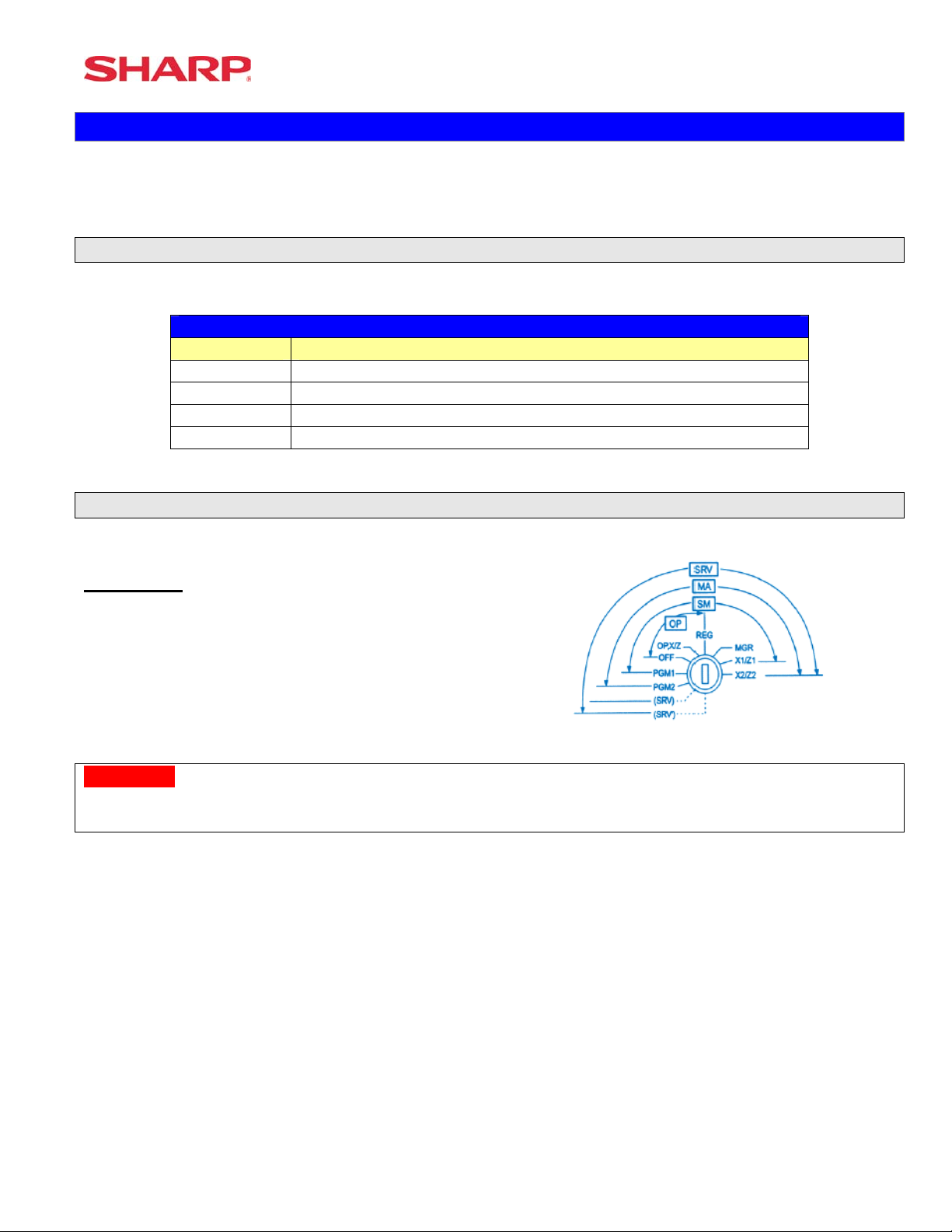
SRV-Mode Related Jobs: (X = indication of availability)
Job No. Description
900 System Presets / Memory Allocation
950 Free Key – Function keys
951 Keyboard Layout – Dept & PLU Link Key Position
990 Special Service Patch Data
2. Entering the SRV-Mode
To enter SRV-mode programming
Procedure:
1) Place the mode switch to the SRV’ position
2) Place the AC power cord into the wall outlet
CAUTION:
Never enter the SRV mode in the middle of a transaction – severe damage may result to the sales
totals.
Specifications subject to change without notice: Revision date 06/05 Page 1 of 266
Page 8
ER-A520/A530 Dealer Knowledge Book
Section-2: Prior to Beginning
The ER-A520/A530 POS terminal should be initialized by executing a master reset. The Program
and Master Reset operations are available in one of the following three types:
Type Description
Program Reset Initializes the hardware and resident program without clearing
memory and totalizers
Master Reset-1 Initializes the hardware and clears the entire memory – restoring
factory initial values
Master-Reset-2 Initializes the hardware and clears the entire memory – restoring
factory initial values and enabling free key layout of the ERA520/A530 “fixed keys”
1. Master Resets:
The Master Reset procedures are primarily performed during installation and setup of the ERA520 and ER-A530 model cash registers. Each has an important role when installing the
equipment.
Follow one the below procedures when you wish to perform a Master Reset.
1. General Rule:
Master Reset: Clears the entire memory and resumes initial values (default program).
Program Reset: Resumes the initial program without clearing memory.
There are 2 methods for performing a Master Reset operation.
1) Master Reset-1: Normal Master Reset (out of box setup).
Clears the entire memory and resumes initial values.
2) Master Reset-2: Enables the ability to change the layout fixed keys in addition to executing
the Master Reset-1.
Fixed Keys: [0] [1] [2] [3] [4] [5] [6] [7] [8] [9] [0] [00] [000] [CL] [.] [@/FOR] [SBTL] [CA/AT]
IMPORTANT NOTES:
During the Master Reset initialization, the following events should be noted.
1) ***MRS*** is displayed on the upper line of the operator display.
2) MASTER RESET*** is printed on the journal tape.
3) The buzzer will beep 3-times.
Page 2 of 266 Specifications subject to change without notice: Revision date 06/05
Page 9
System Preset
2. Master Reset-1 Operations:
There are two possible procedures to use when performing a Master Reset-1 operation.
Follow the below procedure when you wish to perform a program-reset (initialization).
Procedure A:
1) Place the mode switch to the SRV’ position.
2) Place the AC power cord into the wall outlet.
3) Depress and hold the [JOURNAL] feed key.
4) Turn the mode switch from SRV’ -- > SRV position.
Procedure B:
1) Remove the AC power cord from the outlet.
2) Place the mode switch to the SRV position.
3) Depress and hold the [JOURNAL] feed key.
4) Replace the AC power cord into the wall outlet.
Note:
***Procedure A must be used to reset the hardware. Procedure B cannot reset the hardware.
Master Reset-2 Operations:
There are two possible procedures to use in performing a Master Reset-2 operation.
Procedure A:
1) Place the mode switch to the SRV’ position.
2) Place the AC power cord into the wall outlet.
3) Depress and hold the [JOURNAL] & [RECEIPT] feed keys.
4) Turn the mode switch from SRV’ -- > SRV position.
***The operator display will show the fixed function keys
(starting with the [0] key).
5) Program the Fixed Keys by depressing the desired location(s).
6) Once the [CA/AT] key is placed on the keyboard, ***MRS*** will be displayed and the reset
process will continued as outlined in Master Reset-1.
Specifications subject to change without notice: Revision date 06/05 Page 3 of 266
Page 10

ER-A520/A530 Dealer Knowledge Book
Procedure B:
1) Remove the AC power cord from the outlet.
2) Place the mode switch to the SRV position.
3) Depress and hold the [JOURNAL] & [RECEIPT] feed keys.
4) Replace the AC power cord into the wall outlet.
***The operator display will show the fixed function keys (starting with the [0] key).
5) Program the Fixed Keys by depressing the desired location(s).
6) Once the [CA/AT] key is placed on the keyboard, ***MRS*** will be displayed and the reset
process will continued as outlined in Master Reset-1.
Note:
***Procedure A must be used to reset the hardware. Procedure B cannot reset the hardware.
2. Program Reset:
The Program Reset (sometimes referred to as a “Service Reset”) may be achieved with the [SRV]
key (part no. LKGiM7113RCZZ).
1. General Rule:
A Program Reset should be performed under the following general conditions:
1) After the memory allocation setting has been modified.
2) When a device assignment has been modified in COM port assignment.
IMPORTANT NOTE:
During the Program Reset operation, PROGRAM RESET*** is printed on the journal tape.
Follow the below procedure when you wish to perform a program-reset (initialization).
2. Procedures:
Based on the SRV Job#926-B setting, there may be 3 possible procedures in performing a
Program Reset.
Procedure- A:
1) Place the mode switch to the SRV’ position.
2) Place the AC power cord into the wall outlet.
3) Turn the mode switch from SRV’ -- > SRV position.
Page 4 of 266 Specifications subject to change without notice: Revision date 06/05
Page 11

System Preset
Procedure- B:
1) Remove the AC power cord from the outlet.
2) Place the mode switch to the SRV’ position.
3) Replace the AC power cord into the wall outlet.
4) Turn the mode switch clockwise to the SRV position (7 o’clock).
Procedure- C:
1) Remove the AC power cord from the outlet.
2) Place the mode key in the PGM2 position.
3) Depress and hold the [RECEIPT] & [JOURNAL] feed keys.
4) Replace the AC power cord into the wall outlet while holding the keys.
Note:
***Procedure A must be used to reset the hardware. Procedures B and C cannot reset the
hardware.
CAUTION:
Never enter the SRV mode in the middle of a transaction – severe damage may result to the sales
totals.
(based on SRV Job#926-B)
Specifications subject to change without notice: Revision date 06/05 Page 5 of 266
Page 12
ER-A520/A530 Dealer Knowledge Book
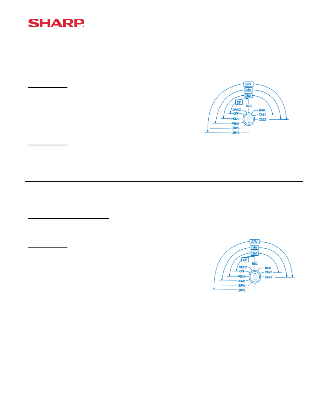
3. Recommended Set Up Procedures
To minimize unnecessary steps when installing the ER-A520 and ER-A530 model cash register,
please perform Job#971 (Memory Allocation), Job#900s (Service Parameters),
Job#950 (Free Key), Job#951 (Keyboard Link Position) followed by “All” PGM2 settings.
The below chart represents the SRV Job# Reference Descriptions.
SRV-Mode Related Jobs: (X = indication of availability)
Job No. Description
901 – 929
980
930 - 939 Report Counters Z-Counters
942 – 943
969
944 PGM2 Mode Secret Code
948 Training Cashier Assignment
949 Training Mode Title Programming
950 Keyboard Layout – Function keys
951 Keyboard – Dept & PLU Keys
971 Memory File Allocation Programming
985 Euro Symbol Programming for the TM-295 Slip Printer
986 Domestic Currency Symbol Programming
987 Language Selection for Text Print
989 Resetting of all Counters and Totalizers
990 Special Service Patch
996, 998 Program Data Send/Receive Function
4. Service Mode Programming
System Parameters
GT Totalizers
Service mode programming is usually performed during the installation process. To change the
System Preset settings, the following key operation is required.
Page 6 of 266 Specifications subject to change without notice: Revision date 06/05
Page 13
System Preset
Section-3: System Preset Job No.
System Preset: 901
Bit Description Data MRS Defaults
A520 A530
---
A
Fixed = 0 (Not Used) ---
---
Enter SUM of Selection ----^
Tax System:
B
Auto Tax 1-4 & Manual Tax System / Canadian Tax (Type 1-10) / Canadian Tax (Type-11:
VAT-on-VAT)
Enter SUM of Selection ----^
Tax Rounding System:
C
- Singapore / Normal
Enter SUM of Selection ----^
Tab Setting:
D
- Decimal setting for display and print
Enter SUM of Selection ----^
0/6/7
8/0
3/2/1/0
NOTE:
• 901-C: The Singapore Tax Rounding method will round the tax to the nearest nickel.
System Preset: 902
0 0
0 0
0 0
2 2
Bit Description Data MRS Defaults
A520 A530
---- ---
A
---- ---
---
Enter SUM of Selection ----^
---- ---
B
---- --Fixed = 0 (Not Used) ---
Enter SUM of Selection ----^
---- ---
C
---
---- ---
Enter SUM of Selection ----^
---- ---
D
---- ---
---- ---
Enter SUM of Selection ----^
0 0
0 0
0 0
0 0
NOTE:
Specifications subject to change without notice: Revision date 06/05 Page 7 of 266
Page 14
ER-A520/A530 Dealer Knowledge Book
System Preset: 903
Bit Description Data
A520 A530
ECR Data Copy (SIO) All RAM data Send/Receive Baud Rate (bps):
A
38400/19200/9600
Enter SUM of Selection ----^
---- ---
B
Measure of Weight for Scale Entries Kg/Lb 2/0
---- ---
Enter SUM of Selection ----^
---
C
Tare Weight Entry is allowed Yes/No 2/0
Scale Weight System 1 Int. & 3 Dec./2 Int. & 2 Dec. 1/0
Enter SUM of Selection ----^
---- --Food Stamp System:
D
Food Stamp Forgiveness / Tax Payable in Food Stamps
Tax in Not Payable in Food Stamps / No Food Stamps
---- ---
Enter SUM of Selection ----^
6/5/4
3/2/1/0
MRS
Defaults
5 5
0 0
0 0
0 0
NOTE:
• 903-A is applicable for the 02FD.exe utility (not online communications)
• Manual Scale Entry allowed (Version-C).
• To enabled Scale entries 906-D must be set = 1
System Preset: 904
Bit Description Data
A520 A530
Date is printed No/Yes 4/0
A
Fraction treatment at gasoline (OIL) q’ty calculation Rounding/Raising to unit/Disregard ---
---- ---
Enter SUM of Selection ----^
Consecutive No. is printed No/Yes 4/0
B
Decimal point position at gasoline (OIL) q’ty calculation ---
---- ---
Enter SUM of Selection ----^
Fraction treatment at gasoline discount Rounding/Raising to unit/Disregard 0/1/2
C
---- ---
---- ---
Enter SUM of Selection ----^
TAB for the gasoline unit price 0.00/0.000 Disable/Enable 0/1
D
Gasoline function Disable/Enable 2/3
---- ---
Enter SUM of Selection ----^
MRS
Defaults
0 0
0 0
0 0
0 0
NOTE:
• 904-A&B applies to Receipts, Slip, and Kitchen Print chits
Page 8 of 266 Specifications subject to change without notice: Revision date 06/05
Page 15
System Preset: 905
System Preset
Bit Description Data
A520 A530
Tax4 Subtotal is printed on Trans. Reports No/Yes 4/0
A
Gross Tax4 & Refund Tax4 Totals are printed on Trans. Reports No/Yes 2/0
Net Tax4 Total is printed on Trans. Reports No/Yes 1/0
Enter SUM of Selection ----^
Tax is printed when the Taxable Subtotal = $0.00 Yes/No 4/0
B
Tax is printed when GST is VAT No/Yes 2/0
Tax is printed when Tax = $0.00 No/Yes 1/0
Enter SUM of Selection ----^
GST Exempt is printed on Trans. Reports No/Yes 4/0
C
Canadian Tax System:
D
Type10/Type9/Type8/Type7/Type6/Type5/Type4/Type3/Type2/Type1
Enter SUM of Selection ----^
Enter SUM of Selection ----^
---- ---
---- ----
9/8/7/6/
5/4/3/2/
1/0
MRS
Defaults
0 0
0 0
0 0
5 5
NOTE:
• 905-C is related to 905-D the Canadian Tax System
System Preset: 906
Bit Description Data
A520 A530
Dept. & PLU/UPC Codes are printed Yes/No 4/0
A
PLU/UPC (EAN) Stock System:
Entry is Inhibited/Error Message and Operation continues/Allowed
Enter SUM of Selection ----^
Bottle Return Function is Enabled Yes/No 4/0
B
Hash Dept. is Enabled Yes/No 2/0
---- ---
Enter SUM of Selection ----^
Multiplication System:
C
PLU/UPC (EAN) Price Look Up at Refund Entry No/Yes 4/0
D
Presetting of the Consecutive No. is Enabled No/Yes 2/0
Fractional Qty System is enabled (3 decimal places) Yes/No 1/0
Split-Price/Successive Multiplication/Multiplication 2/1/0
Enter SUM of Selection ----^
Enter SUM of Selection ----^
2/1/0
MRS
Defaults
0 0
0 0
2 2
0 0
NOTE:
• 906-D must not be changed until after totalizers are reset (Qty 0 Æ 0.000 & vice-versus).
• Fractional entries are disabled when a SCALE is enabled in PGM2 Job #2690 programming.
• 906-D must be set = 1 to enable “SCALE”.
Specifications subject to change without notice: Revision date 06/05 Page 9 of 266
Page 16
ER-A520/A530 Dealer Knowledge Book
System Preset: 907
Bit Description Data
A520 A530
---- ---
A
Fixed = 0 ---
---- ---
Enter SUM of Selection ----^
---- ---
B
UPC (EAN) Code Printing on Journal No/Yes 2/0
UPC (EAN) Code Printing on Receipt No/Yes 1/0
Enter SUM of Selection ----^
X Report is Enforced prior to Ind./All Cashier CCD Yes/No 4/0
C
---- 2/0
Minus Dept. and PLU/UPC (EAN) items are Enabled Yes/No 1/0
Enter SUM of Selection ----^
CCD Compulsion on ALL Server 0
D
For Individual Server CCD 1
Non-Compulsory CCD 2
Enter SUM of Selection ----^
MRS
Defaults
0 0
0 0
1 1
0 0
NOTE:
• To enable Coupon PLU items 907-D must be set = 1
System Preset: 908
Bit Description Data
A520 A530
GT1 is printed on the Trans.-Z Report No/Yes 4/0
A
GT2 is printed on the Trans.-Z Report No/Yes 2/0
GT3 is printed on the Trans.-Z Report No/Yes 1/0
Enter SUM of Selection ----^
GT1 is printed on the Trans.-X Report Yes/No 4/0
B
GT2 is printed on the Trans.-X Report Yes/No 2/0
GT3 is printed on the Trans.-X Report Yes/No 1/0
Enter SUM of Selection ----^
VOID-mode operations affect the Hourly Report Yes/No 4/0
C
X//Z1 Reports may taken in X2/Z2 Mode No/Yes 2/0
Consecutive No. is Reset upon a Trans.-Z Report Yes/No 1/0
Enter SUM of Selection ----^
X/Z Report Printing: Journal only/Receipt & Journal 4/0
D
---- --Trans.-Z1 Report resets the GT Yes/No 1/0
Enter SUM of Selection ----^
MRS
Defaults
0 0
0 0
0 0
0 0
NOTE:
• 908-D: The X/Z Report printing option does not apply to Individual Cashier Report
Page 10 of 266 Specifications subject to change without notice: Revision date 06/05
Page 17
System Preset: 909
System Preset
Bit Description Data
A520 A530
---- ---
A
Training GT is printed on the Trans.-X Report Yes/No 2/0
Training GT is printed on the Trans.-Z Report No/Yes 1/0
Enter SUM of Selection ----^
PLU/UPC (EAN) Item Data is printed on the Z Report No/Yes 4/0
B
---- ---
---- ---
Enter SUM of Selection ----^
VOID-mode & MGR VOID is printed on the Trans.-Z2 Report No/Yes 4/0
C
VOID-mode & MGR VOID is printed on the Trans.-Z1 Report No/Yes 2/0
---- ---
Enter SUM of Selection ----^
---- ---
D
Fixed = 0 ---
---- ---
Enter SUM of Selection ----^
MRS
Defaults
2 2
0 0
0 0
0 0
NOTE:
• 909-B: No Sales Data is printed for the PLU/UPC (EAN)-Z Report when = 4
System Preset: 910
Bit Description Data
A520 A530
---- ---
A
Overlapped Cashier Function Yes/No 1/0
---- ---
Enter SUM of Selection ----^
Cashier Code Display Appear/Hidden 2/0
B
Auto Sign Off at the End of the Transaction
---- ---
---- ---
C
Fixed = 0 ---
---- ---
(Fixed): Server/Cashier system is code entry 4
D
---- ---
---- ---
Yes (Everytime) / No
After Cashier Z1 Only
Enter SUM of Selection ----^
Enter SUM of Selection ----^
Enter SUM of Selection ----^
1/0
MRS
Defaults
0 0
2 2
0 0
4 4
NOTE:
• 910-A: The Cash drawer opening is based on the Individual Server preset
Specifications subject to change without notice: Revision date 06/05 Page 11 of 266
Page 18
ER-A520/A530 Dealer Knowledge Book
System Preset: 911
Bit Description Data
A520 A530
---- ---
A
---- --Fractional Qty System: Ignored/Round-Up/Round-Off 2/1/0
Enter SUM of Selection ----^
C/D Check of UPC (EAN) Yes/No 4/0
B
---- ---
---- ---
Enter SUM of Selection ----^
---- ---
C
Fixed = 0 ---
---- ---
Enter SUM of Selection ----^
RECEIPT/SLIP header format
Format 1: Normal sized Consec. #, Server Name and code 0
D
Format 2: Double-sized Consec. #, normal sized Server Name and code 2
Format 3: Double-sized Consec. #, and Server code
(Server Name not printed)
Enter SUM of Selection ----^
4
MRS
Defaults
0 0
0 0
0 0
0 0
NOTE:
• 911-A: Is ignored for Scale operations
Page 12 of 266 Specifications subject to change without notice: Revision date 06/05
Page 19
System Preset: 912
System Preset
Bit Description Data
A520 A530
---- ---
A
---- --Date Print Format YYMMDD/DDMMYY/MMDDYY 2/1/0
Enter SUM of Selection ----^
---- ---
B
---- --Time Clock System 24-Hour System/12-Hour System 1/0
Enter SUM of Selection ----^
Receipt After-Transaction Format Detailed/Totals only 4/0
C
Copy Receipt Function is Enabled Yes/No 2/0
Receipt Footer Print Control By Media Preset/All Receipts 1/0
Enter SUM of Selection ----^
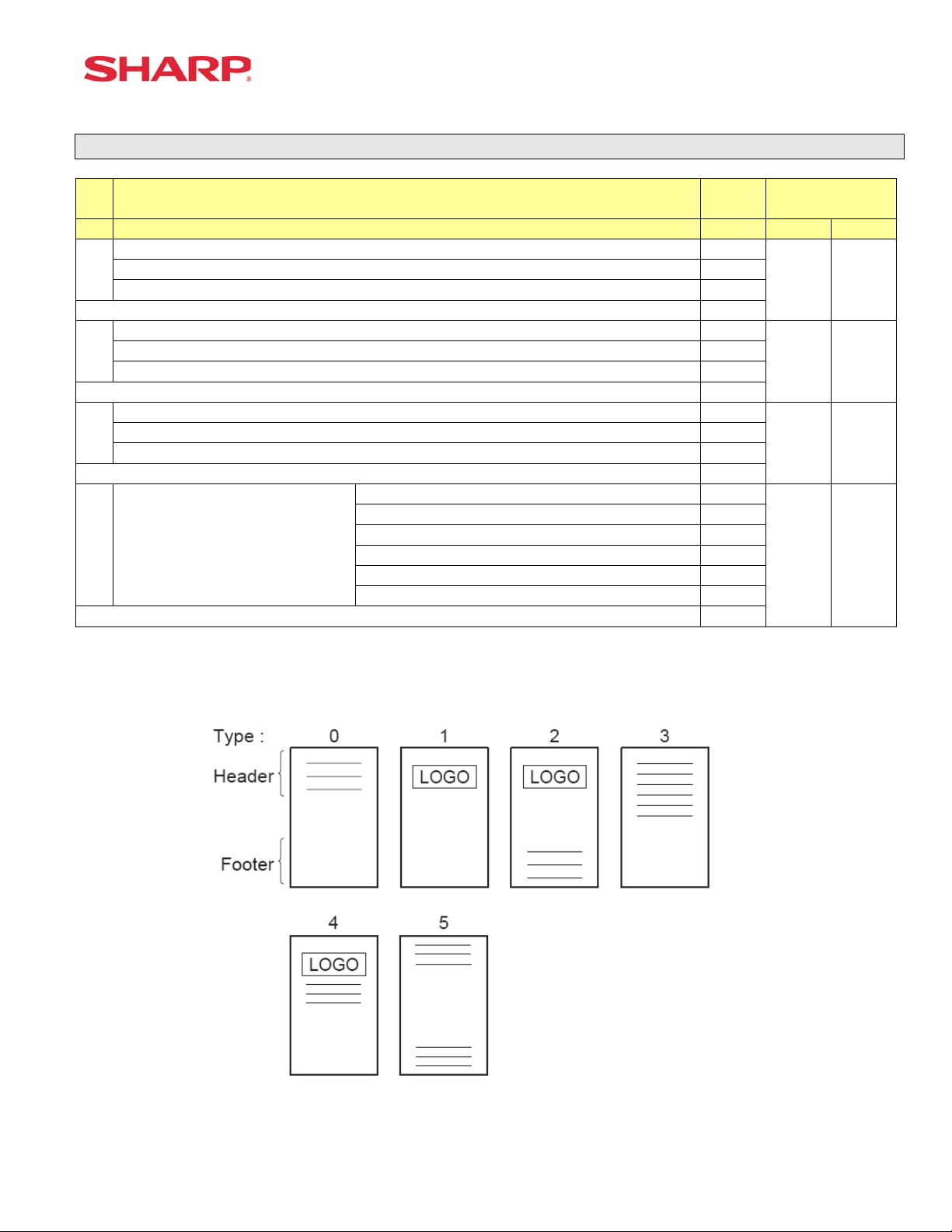
3-Line Header – No Logo Graphic Stamp 0
Graphic Logo Stamp only 1
D Logo Message Control:
Graphic Logo Stamp & 3-Line Footer 2
6-Line Header – No Stamp 3
Graphic Logo and 3-Line Header 4
3-Line Header – No Stamp/3-Line Footer 5
Enter SUM of Selection ----^
MRS
Defaults
0 0
0 0
6 6
1 0
NOTE:
• 912-D: The Graphic Logo STAMP – Must use SDW to upload Graphical Logos to the ECRs.
• 912-D: The Graphic Logo bitmap should be 288 dots (w) x 130 dots (h) and black & white only.
Specifications subject to change without notice: Revision date 06/05 Page 13 of 266
Page 20
ER-A520/A530 Dealer Knowledge Book
System Preset: 913
Bit Description Data
A520 A530
---- ---
A
---- --VP Total Amounts Contains: Tendered Amount/Total Amount 1/0
Enter SUM of Selection ----^
Subtotal is printed when the [SBTL] key is depressed Yes/No 4/0
B
MDSE Subtotal is printed when the [MDSE] key is depressed Yes/No 2/0
Escaping Compulsory VP and SLIP print is Enabled Yes/No 1/0
Enter SUM of Selection ----^
---- ---
C
Error-Tone System Until [CL] is depressed/2 seconds 2/0
Keyboard Buffering is Enabled No/Yes 1/0
Enter SUM of Selection ----^
Compulsory Drawer Closed prior to operation is enabled Yes/No 4/0
D
Error System “Misoperation”/One-Shot Error Only 2/0
Key Touch-Tone is enabled No/Yes 1/0
Enter SUM of Selection ----^
MRS
Defaults
0 0
1 1
0 0
4 4
NOTE:
• 913-B: The sequence for escaping “Compulsory” VP or SLIP print operations:
Æ [.] Æ [SLIP or PRINT]
System Preset: 914
Bit Description Data
A520 A530
Receipts are printed upon [NO SALE] operations No/Yes 4/0
A
The [NO SALE] function is combined with the [CASH] key Yes/No 2/0
Tax Delete function is Enabled Yes/No 1/0
Enter SUM of Selection ----^
---- ---
B
---- --The [NO SALE] function is allowed after a Non-Add No. entry Yes/No 1/0
Enter SUM of Selection ----^
---- ---
C
VOID-mode is Enabled No/Yes 2/0
Non-Add # Entry is Compulsory at the beginning of each Trans. Yes/No 1/0
Enter SUM of Selection ----^
Manual Tax entry is Enabled No/Yes 4/0
D
Check-Cashing function is Enabled Yes/No 2/0
Non-Add # Entry is Enabled No/Yes 1/0
Enter SUM of Selection ----^
MRS
Defaults
1 1
1 1
0 0
0 0
NOTE:
Page 14 of 266 Specifications subject to change without notice: Revision date 06/05
Page 21
System Preset
System Preset: 915
Bit Description Data MRS
A520 A530
---- ---
A
---- --Fixed = 0 ---
Enter SUM of Selection ----^
---- ---
B
Fixed = 0 ---
---- ---
Enter SUM of Selection ----^
---- ---
C
SBTL (-) or SBTL (%) within the same Transaction Once/Any No. Times 2/0
Enter SUM of Selection ----^
Fixed = 0 ---
D
---- ---
---- ---
Enter SUM of Selection ----^
NOTE:
System Preset: 916
0 0
0 0
0 0
0 0
Bit Description Data
A520 A530
---- ---
A
---- --Print when the No. Text Characters overlap the Amount 2-Line/Truncate 1/0
Enter SUM of Selection ----^
Charge Media Finalization when the Amount = $0.00 Yes/No 4/0
B
---- --Food Stamp SBTL is Compulsory before FS-Tender Yes/No 1/0
Enter SUM of Selection ----^
Allow the MDSE SBTL to go Negative No/Yes 4/0
C
[SBTL] Entry is Compulsory before Tendering Finalization Yes/No 2/0
[SBTL] Entry is Compulsory before Direct Finalization Yes/No 1/0
Enter SUM of Selection ----^
Coupon PLU Totalizer prints on the Trans.-(X/Z) Reports No/Yes 4/0
D
NET Sales SBTL (NET1) is printed on the Trans.-(X/Z) Reports No/Yes 2/0
Check-Change Totalizer is printed on the Trans.-(X/Z) Reports No/Yes 1/0
Enter SUM of Selection ----^
MRS
Defaults
1 1
4 4
0 0
0 0
NOTE:
Specifications subject to change without notice: Revision date 06/05 Page 15 of 266
Page 22
ER-A520/A530 Dealer Knowledge Book
System Preset: 917
Bit Description Data MRS
A520 A530
Tax1 Subtotal is printed on Trans. Reports No/Yes 4/0
A
Gross Tax1 & Refund Tax1 Totals are printed on Trans. Reports No/Yes 2/0
Net Tax1 Total is printed on Trans. Reports No/Yes 1/0
Enter SUM of Selection ----^
Tax2 Subtotal is printed on Trans. Reports No/Yes 4/0
B
Gross Tax2 & Refund Tax2 Totals are printed on Trans. Reports No/Yes 2/0
Net Tax2 Total is printed on Trans. Reports No/Yes 1/0
Enter SUM of Selection ----^
Tax3 Subtotal is printed on Trans. Reports No/Yes 4/0
C
Gross Tax3 & Refund Tax3 Totals are printed on Trans. Reports No/Yes 2/0
Net Tax1 Total is printed on Trans. Reports No/Yes 1/0
Enter SUM of Selection ----^
Total Tax is printed on the Trans.-(X/Z) Reports No/Yes 4/0
D
Gross & Ref. Manual Tax Totals are printed on Trans. Reports No/Yes 2/0
Net Manual Tax Totalizer is printed on Trans.-(X/Z) Reports No/Yes 1/0
Enter SUM of Selection ----^
NOTE:
System Preset: 918
0 0
0 0
0 0
0 0
Bit Description Data MRS
A520 A530
Assoc. PLU Text of Combo Meals is printed No/Yes 4/0
A
Direct-Tender for 2nd or subsequent tender is allowed Yes/No 2/0
Combo Meal Kitchen Printer printing is by Combo Meal’s KP/by PLU’s KP 1/0
Enter SUM of Selection ----^
---- ---
B
PLU Text is printed in RED when the unit price is $0.00 Yes/No 2/0
Fractional entries allowed for non-Scalable Dept. & PLU items No/Yes 1/0
Enter SUM of Selection ----^
---- ---
C
Kitchen Printer output Groups Like Items No/Yes 2/0
Kitchen Printer output prints Dept. & PLU Text in Double-Sized Yes/No 1/0
Enter SUM of Selection ----^
Tip paid includes cash tip No/Yes 4/0
D
Clearing of tip totalizer at server Z1 report Yes/No 2/0
Printing of tip totalizer on the server report Yes/No 1/0
Enter SUM of Selection ----^
2 2
2 2
3 3
3 3
NOTE:
Page 16 of 266 Specifications subject to change without notice: Revision date 06/05
Page 23
System Preset
System Preset: 919
Bit Description Data MRS
A520 A530
Guest Check System is Guest Look-up Compulsory/Non-compulsory
PB Look-up Compulsory/Non-compulsory
Manual PB-CB Compulsory/Non-compulsory
A
Guest Check/PB Look-up code upon Reorder
(Only when 919-B =0 or 4)
----
Cashier No. is Checked at PBLU Reorder No/Yes 4/0
B
---- --Guest Check Number-System Entry Manual/Auto-Generate 1/0
---- ---
C
[PBLU] Entry is Compulsory Yes/No 2/0
Amount Prints when PLU/UPC (EAN) Unit Price is $0.00 Yes/No 1/0
Normal SBTL is printed in addition to the Conversion SBTL No/Yes 4/0
D
---- --Foreign Currency Format Omit Decimal Digits/Not 1/0
Compulsory/Non-compulsory 1/0
Enter SUM of Selection ----^
Enter SUM of Selection ----^
Enter SUM of Selection ----^
Enter SUM of Selection ----^
NOTE:
System Preset: 920
5/4
3/2
1/0
0 0
4 4
0 0
0 0
Bit Description Data MRS
A520 A530
Combine like items for GLU items printed on a Bill No/Yes 0/4
A
---- ---
---- ---
Enter SUM of Selection ----^
---- ---
B
Fixed = 0 ---
---- ---
Enter SUM of Selection ----^
---- ---
C
---- ---
---- ---
Enter SUM of Selection ----^
---
D ----
---
---
---
Enter SUM of Selection ----^
0 0
0 0
0 0
0 0
NOTE:
Specifications subject to change without notice: Revision date 06/05 Page 17 of 266
Page 24
ER-A520/A530 Dealer Knowledge Book
System Preset: 921
Bit Description Data MRS
A520 A530
Convert UPC-E to UPC-A Code Yes/No 4/0
A
---- ---
---- ---
Enter SUM of Selection ----^
Fixed = 0 ---
B
---
---
Bill printing method Items are printed and deleted/Items reprint each bill 0/1
C
---
---
Tip paid is automatically executed upon Ind. Server/Cashier resetting report
when a Tip exists.
D
Enter SUM of Selection ----^
Yes/No 0/4
NOTE:
System Preset: 922
---
---
0 0
0 0
0 0
0 0
Bit Description Data
A520 A530
Fixed = 0 ---
A
---- ---
---- ---
Enter SUM of Selection ----^
Type coin dispenser can issue $1 coins No/Yes 0/1
B
---- ---
---- ---
Enter SUM of Selection ----^
---- ---
C
---- --Fixed = 0 ---
Enter SUM of Selection ----^
---- ---
D
---- --Fixed = 0 ---
Enter SUM of Selection ----^
MRS
Defaults
0 0
0 0
0 0
0 0
NOTE:
Page 18 of 266 Specifications subject to change without notice: Revision date 06/05
Page 25
System Preset: 923
System Preset
Bit Description Data
A520 A530
---- ---
A
---- --(Fixed) ---
Enter SUM of Selection ----^
(Fixed)
B
---- ---
---- ---
Enter SUM of Selection ----^
---- ---
C
(Fixed) --(Fixed)
Enter SUM of Selection ----^
(Fixed) ---
D
(Fixed) ---
Enter SUM of Selection ----^
MRS
Defaults
0 0
0 0
0 0
0 0
NOTE:
System Preset: 924
Bit Description Data MRS
A520 A530
---- ---
A
---- --(Fixed) ---
Enter SUM of Selection ----^
(Fixed) ---
B
---- ---
---- ---
Enter SUM of Selection ----^
---- ---
C
(Fixed) --(Fixed) ---
Enter SUM of Selection ----^
---
D
---
Enter SUM of Selection ----^
0 0
0 0
0 0
0 0
NOTE:
Specifications subject to change without notice: Revision date 06/05 Page 19 of 266
Page 26
ER-A520/A530 Dealer Knowledge Book
System Preset: 925
Bit Description Data
A520 A530
---
A
---
---- ---
Enter SUM of Selection ----^
---- ---
B
---
---
Enter SUM of Selection ----^
C
Enter SUM of Selection ----^
---- ---
D
---
---
Enter SUM of Selection ----^
MRS
Defaults
0 0
0 0
0 0
0 0
NOTE:
System Preset: 926
Bit Description Data
A520 A530
---- ---
A
Direct Voids and the Voided item is printed on the KP No/Yes 2/0
Past Voids and the Voided item is printed on the KP No/Yes 1/0
Enter SUM of Selection ----^
Program Reset via PGM2-Mode is Enabled Yes/No 4/0
B
Refunded Data is sent to the KP No/Yes 2/0
---- ---
Enter SUM of Selection ----^
Fixed = 0
C
---
---
Enter SUM of Selection ----^
Fixed = 0
D
---- ---
---- ---
Enter SUM of Selection ----^
---
MRS
Defaults
0 0
0 0
0 0
0 0
NOTE:
• When REFUND Data is preset to print to the KP. It will print in RED.
• When REFUND Data is preset NOT to print to the KP. It will print in BLACK.
Page 20 of 266 Specifications subject to change without notice: Revision date 06/05
Page 27
System Preset: 927
System Preset
Bit Description Data
A520 A530
Fixed = 0
A
---- ---
---- ---
Enter SUM of Selection ----^
Fixed = 0
B
---- ---
---- ---
Enter SUM of Selection ----^
Fixed = 0
C
---- ---
---- ---
Enter SUM of Selection ----^
Fixed = 0
D
---- ---
---- ---
Enter SUM of Selection ----^
---
---
---
---
MRS
Defaults
0 0
0 0
0 0
0 0
NOTE:
System Preset: 928
Bit Description Data
A520 A530
---- ---
A
---- --Slip Logo is printed on Slip Printer Yes/No 1/0
Enter SUM of Selection ----^
---- ---
B
Validation Message is printed on Slip for Checks & Charges Yes/No 2/0
Header Line is printed on Slip on Reorder Entries No/Yes 1/0
Enter SUM of Selection ----^
PLU/UPC (EAN) is printed on the [BILL] when the unit price = $0.00 No/Yes 4/0
C
Combo Meal Individual PLU Item Text is printed on the [BILL] No/Yes 2/0
---- ---
Enter SUM of Selection ----^
Compulsory Bill Print System:
Compulsory for GLU/PBLU entries 2
D
Compulsory for every entry 1
Compulsory based on Media key preset 0
Enter SUM of Selection ----^
MRS
Defaults
0 0
0 0
0 0
0 0
NOTE:
Specifications subject to change without notice: Revision date 06/05 Page 21 of 266
Page 28
ER-A520/A530 Dealer Knowledge Book
System Preset: 929
Bit Description Data
---- ---
A
---- --KP Print format for Media Keys Detailed/Summary 1/0
Enter SUM of Selection ----^
Server, Transaction resetting allowed with open Guest Checks.
B
---- -- 0
Enter SUM of Selection ----^
When Closed Check file is full Inhibit registration/Continue
C
---- ---
---
Enter SUM of Selection ----^
--Taxable Status of PLU/UPC (EAN),
D
SET at “Non-Taxable” by PGM
mode
---- ---
Taxable Status of PLU/UPC set
According to its Associated
Department
Enter SUM of Selection ----^
Yes/No 1/0
0/1
0/1
MRS
Defaults
0 0
0 0
0 0
0 0
NOTE:
System Preset: 980
Bit Description Data
A520 A530
---- ---
A
---- --Fixed = 0 0
Enter SUM of Selection ----^
---- ---
B
---- --HASH department entries are added to the Hourly Report Yes/No 1/0
Enter SUM of Selection ----^
---- ---
C
---- --Fixed = 0 0
Enter SUM of Selection ----^
---- ---
D
Fixed = 0 0
0
Enter SUM of Selection ----^
MRS
Defaults
0 0
0 0
0 0
0 0
NOTE:
Page 22 of 266 Specifications subject to change without notice: Revision date 06/05
Page 29
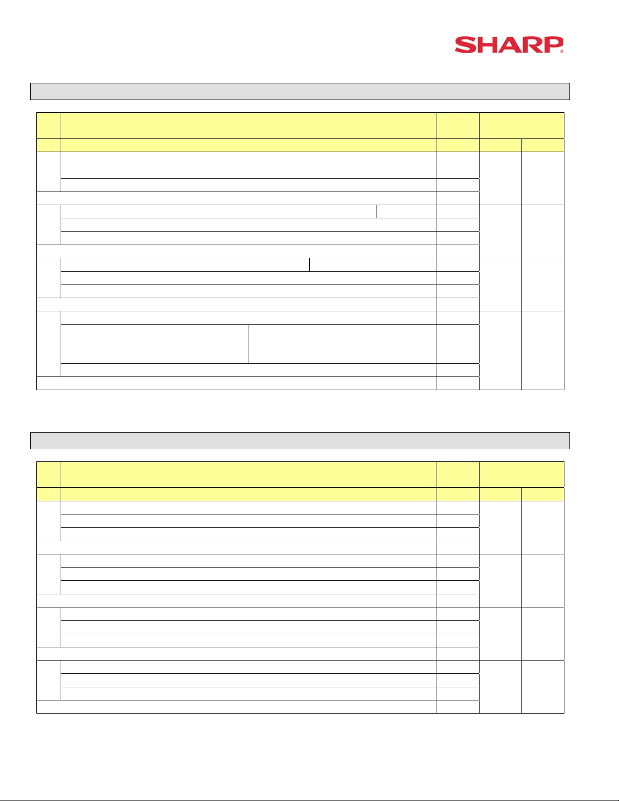
Reset Report Counters – Z1/Z2
930: Z1 General Report Counter
931: Hourly Z1 Report Counter
934: PLU Z1 Report Counter
935: Cashier Z1 Report Counter
936: GLU/PBLU Z1 Report Counter
937: Z2 General Report Counter
939: Daily Net Z2 Report Counter
System Preset
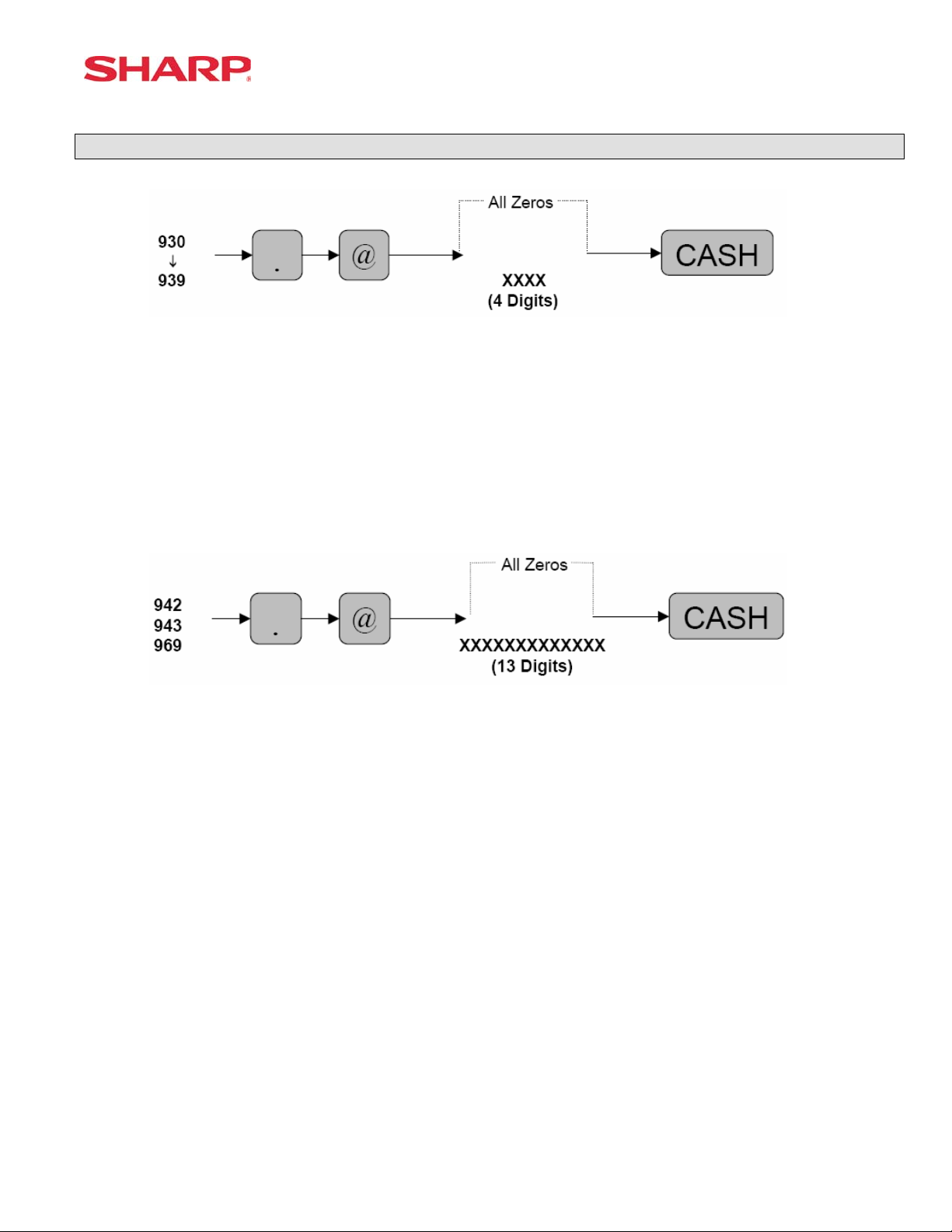
942: GT2 (Positive GT)
943: GT3 (Negative GT)
969: Training GT
Note: The Net GT is obtained from GT2 and GT3 calculations
MRS = 0000000000000
Specifications subject to change without notice: Revision date 06/05 Page 23 of 266
Page 30
ER-A520/A530 Dealer Knowledge Book
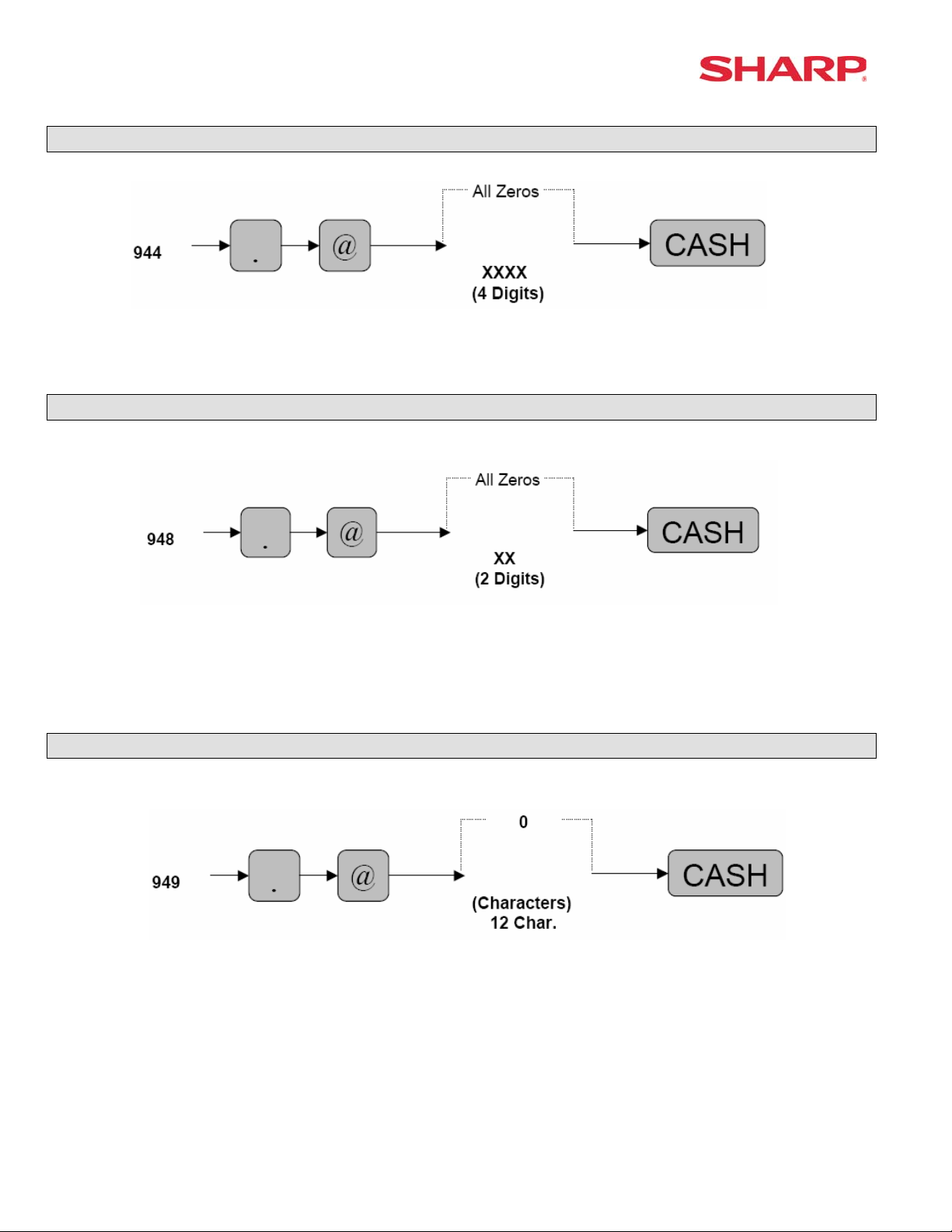
PGM-2 Mode Secret Code Programming
MRS = 0000
Server/Cashier Training Programming
XX: Cashier/Server Code
MRS = 00
Training Mode Title Programming
MRS = **TRAINING**
Page 24 of 266 Specifications subject to change without notice: Revision date 06/05
Page 31

Euro Symbol Programming
X: 0 = “spaces”
1 = Euro Symbol
MRS = 0 (spaces)
Domestic Currency Symbol
System Preset
MRS = **$**
Note: The characters are entered using the programming key layout or by entering the numeric
codes shown on page 20. This symbol is printed with positive amounts of domestic
currency and will be printed to the left-side of the amount.
Specifications subject to change without notice: Revision date 06/05 Page 25 of 266
Page 32

ER-A520/A530 Dealer Knowledge Book
Language Setting For Text
X: 0 = English Text
1 = French Text
2 = Spanish Text
MRS = 0 (English)
Note: The following text is changed upon the setting above:
- FUNCTION text
- CASHIER text
- MESSAGE text (e.g. Logo, etc.)
Resetting of all Counters and Totalizers
Page 26 of 266 Specifications subject to change without notice: Revision date 06/05
Page 33

System Preset Reading – SRV Mode
1. Procedures:
1) Place the SRV key to the SRV-Mode position
2) Enter the following sequence:
900
@ CASH
2. Print Out:
System Preset
Specifications subject to change without notice: Revision date 06/05 Page 27 of 266
Page 34

Page 35

Section-2: Free Key Layouts
Page 36

Page 37

Free Key Layouts
Function Key Layout
XXX: Function No. 1-130
: 999 (for inhibiting a key)
MRS = Standard “out-of-the-box” key layout
Note: If the “fixed” function keys are accidentally placed in the wrong position, it may be
necessary to restore the MRS default keyboard in order to continue.
Note: Only the keyboard layout is affected; PGM2 Mode data are retained.
Function Key Layout
XXX: 1-82 (ER-A520)
: 1-151 (ER-A530)
: 999 (for inhibiting a key location)
MRS = Standard “out of box” key layout
Note: The Key No. programmed in this programming will be used in the PGM2 mode
programming for assigning direct Dept. and/or PLU keys on the keyboard.
Specifications subject to change without notice: Revision date 06/05 Page 31 of 266
Page 38

ER-A520/A530 Dealer Knowledge Book
Function Key Reference Chart
1. ER-A520
Note: The shaded keys are fixed and cannot be assigned to Key Functions.
2. ER-A530
Note: The shaded keys are fixed and cannot be assigned to Key Functions.
Page 32 of 266 Specifications subject to change without notice: Revision date 06/05
Page 39

Free Key Layouts
Free Key Layout Reading – SRV Mode
2. Procedures:
1) Place the SRV key to the SRV-Mode position
2) Enter the following sequence:
950
@ CASH
Specifications subject to change without notice: Revision date 06/05 Page 33 of 266
Page 40

ER-A520/A530 Dealer Knowledge Book
3. Keyboard Key Positions: Physical Key Location Number
1) Example from the ER-A520 Key No. Layout:
Note: All keys except the receipt paper feed and journal paper feed keys can be re-positioned.
2) Example from the ER-A530 Key No. Layout:
Note: All keys except the receipt paper feed and journal paper feed keys can be re-positioned.
Page 34 of 266 Specifications subject to change without notice: Revision date 06/05
Page 41

Free Key Layouts
4. Reference Free Keys to Keyboard:
1) Example from the ER-A520 default Key Layout:
Receipt Journal NC
16
SLIP
5
CONV
4
%1
3
%2
2
RFND
1
RCPT
10
RA
9
PO
8
(-)
7
VOID
6
KEY NO.
PBLU
15
FINAL
14
TAX
13
TAX
SHIFT
12
#/TM
11
22
21
20
19
18
17
CASH
28
@/FOR
27
26
25
24
23
PLU/
#
UPC
34
.
33
7
8
32
4
5
31
1
2
30
0
0
29
FREE FUNCTION KEY
PLU/
UPC
40
CL
39
9
38
6
37 43
3
36 42
00
34
46
45
44
41
PRICE
CHANGE
52
005
51
004
50
003
49
002
48
001
47
PRICE
CHANGE
58
010
57
009
56
008
55
007
54
006
53
AMT
52
015
63
014
62
013
61
012
60
011
59
INQ
70
020
69
019
68
018
67
017
66
0016
65
FS
SHIFT
76
FS
TEND
75
NS
74
CHK
73
MDSE
SBTL
72
CA/AT
71
AUTO
1
82
AUT O
2
81
CH1
80
CH2
79
SBTL
78
CA/AT
77
Specifications subject to change without notice: Revision date 06/05 Page 35 of 266
Page 42

ER-A520/A530 Dealer Knowledge Book
2) Example from the ER-A530 Default Key Layout:
RCPT JRNL 91
79
8
67
7
56
6
45
5
34
4
23
3
12
2
1
1
80
16
68
15
57
14
46
13
35
12
24
11
13
10
2
9
25
81
24
69
23
58
22
47
21
36
20
25
19
14
18
3
17
92
93
94
95
96
97
98
99
34
43
52
61
70
79
88
97
82
83
84
85
86
87
88
89
33
42
51
60
69
78
87
96
70
71
72
73
74
75
76
77
32
41
50
59
68
77
86
95
59
60
61
62
63
64
65
66
31
40
49
58
67
76
85
94
48
49
50
51
52
53
54
55
30
39
48
57
66
75
84
93
37
38
39
40
41
42
43
44
29
38
47
56
65
74
83
92
26
27
28
29
30
31
32
33
28
37
46
55
64
73
82
91
15
16
17
18
19
20
21
22
27
36
45
54
63
72
81
90
4
26
35
6
5
44
7
8
9
10
80
11
89
53
62
71
100
106
90
105
78
104
SERV
#
103
@/FOR
102
7
101
4
100
1
99
0
98
PLU NO. EX.
PLU1
KEY NO.
L1
115
RCPT
114
VOID
113
RFND
112
.
111
8
110
5
109
2
108
00
107
L2
124
%
123
INQ
122
PLU/
SUB
121
CL
120
9
119
6
118
3
117
000
116
FREE FUNCTION KEY
L3
133
(-)
132
RP
SEND
131
NC
130
PBAL
129
SRVC
128
FINAL
127
MDSE
SBTL
126
SBTL
125
AUTO
1
142
AUTO
2
141
AUTO
3
140
CONV
139
CH1
138
CH2
137
CH3
136
CHK
135
CA/AT
134
Page 36 of 266 Specifications subject to change without notice: Revision date 06/05
Page 43

Free Key Layouts
Key Location No. Reading
1. Procedure:
1) Place the SRV key to the SRV-Mode position
2) Enter the following sequence:
951
2. Print Out:
@ CASH
Specifications subject to change without notice: Revision date 06/05 Page 37 of 266
Page 44

ER-A520/A530 Dealer Knowledge Book
Function Key ListKey
No. FUNCTION KEY TEXT (8 Char.)
0 KEY 0 K E Y 1
2 1 KEY 1 K E Y
3 2 KEY 2 K E Y
4 3 KEY 3 K E Y
5 4 KEY 4 K E Y
6 5 KEY 5 K E Y
7 6 KEY
8 7 KEY
9 8 KEY 8 K E Y
10 9 KEY 9 K E Y
11 00 KEY
12 000KEY
13 DECIMAL POINT . K E Y
14 CLEAR C L EAR
15 @/FOR @ / F O R
16 SUB TOTAL S B T L
17 CA/AT C A/ AT
18 MERCHANDISE SUB-TOTAL M D S S T
19 TRAY SUB-TOTAL T R Y S T
20 GASOLINE SALES SUB-TOTAL GA S ST
21 NON ADD/TIME # / T M
22 NO SALE N S
23 PLU/SUB/UPC P L U / S B
REFUND TYPE OF SALES R F S A L
24
LEVEL SHIFT# L E V E L #
25
26 LEVEL1 L 1
27 L 2
LEVEL2
28 LEVEL3 L 3
29 LEVEL4 L 4
30 LEVEL5 L 5
31 PRICE SHIFT # S F T #
32 PRICE1 P 1
33 PRICE2 P 2
34 PRICE3 P 3
35 PRICE4 P 4
36 PRICE5 P 5
37 PRICE6 P 6
38 TAX1 SHIFT T A X 1 S F
39 TAX2 SHIFT T A X 2 S F
40 TAX3 SHIFT T A X 3 S F
41 TAX4 SHIFT T A X 4 S F
42 FS SHIFT F S
43 VALIDATION PRINT P R I N T
44 SLIP (BILL) S L I P
45 COPY/AFTER TRANSACTION RECEIPT RCP T
46 VOID V OID
6 K E Y
7 K E Y
0 0 K E Y
00 0K EY
P .
S F T
Page 38 of 266 Specifications subject to change without notice: Revision date 06/05
No. FUNCTION KEY TEXT (8 Char.)
47 REFUND R F N D
48 RETURN R E T U R N
49 %1 % 1
50 %2 %2
51 %3 %3
52 %4 %4
53 %5 %5
54 (-) 1 (-) 1
55 (-) 2 (-) 2
56 (-) 3 (-) 3
57 (-) 4 (-) 4
58 (-) 5 (-) 5
59 TAX TAX
60 COVER COUNT CVCNT
61 AUTO AUTO
62 AUTO2 AUTO2
63 AUTO3 AUTO3
64 AUTO4 AUTO4
65 AUTO5 AUTO5
66 AUTO6 AUTO6
67 AUTO7 AUTO7
68 AUTO8 AUTO8
69 AUTO9 AUTO9
70 AUT010 AUTO10
71 CASH2 CA2
72 CASH3 CA3
73 CASH4 CA4
74 CASH5 CA5
75 CHECK CHECK
76 CHECK2 CHECK2
77 CHECK3 CHECK3
78 CHECK4 CHECK4
79 CHECK5 CHECK5
80 CHARGE1 CH1
81 CHARGE2 CH2
82 CHARGE3 CH3
83 CHARGE4 CH4
84 CHARGE5 CH5
85 CHARGE6 CH6
86 CHARGE7 CH7
87 CHARGE8 CH8
88 CHARGE9 CH9
89 CURRENCY CONVERSION1 CONV1
90 CURRENCY CONVERSION2 CONV2
91 CURRENCY CONVERSION3 CONV3
Page 45

Free Key Layouts
No. FUNCTION KEY TEXT (8 Char.)
92 CURRENCY CONVERSION4 CONV4
93
GLU/PBLU/PB PBAL/PB
94 NEW CHECK/PB N. C. /CB
95 SERVICE SRVC
96 FINAL FINAL
97 DEPOSIT DEPO
98 DEPOSIT REFUND DEP. RF
99 FS TEND FSTEND
100 RECEIVED ON ACCOUNT RA
101 RECEIVED ON ACCOUNT2 RA 2
102 PAID OUT PO
103 PAID OUT2 PO 2
104 SERVER NUMBER SRV#
105 BIRTHDAY BIRTH
106 DEPT# DEPT#
107 SCALE SCALE
108 OPEN TARE OPN TR
109 AMOUNT AMT
110 REPEAT REPEAT
111 INQUIRE INQ
112 NO DELETE (UPC) NO DEL
113 PRICE CHANGE PR CHG
114 REMOTE PRINTER SEND RP SND
115 CHARGE TIP CH TIP
116 CASH TIP CA TIP
117 TIP PAID TIP PD
118 GRATUITY EXEMPT GRT EX
119 EDIT TIP ED TIP
120 BILL TRANSFER B. T.
121 BILL SEPARATE B. S.
122 TRANS OUT TR OUT
123 TRANS IN TR IN
124 GLU RECALL GLU RC
125 WASTE MODE WASTE
126 EAT IN1 EATIN1
127 EAT IN2 EATIN2
128 EAT IN3 EATIN3
129 CONDIMENT NEXT C. NEXT
130 CONDIMENT CANCEL C. CANCEL
999 INHIBIT INHIBIT
Specifications subject to change without notice: Revision date 06/05 Page 39 of 266
Page 46

Page 47

Section-3: File Allocation
Page 48

Page 49

Memory Allocation
971
File Allocation
@/FOR.
XX
@/FOR
YYYYY
(Type 0,1)
CA/AT
@/FOR
(Type 2)
ZZZZZ
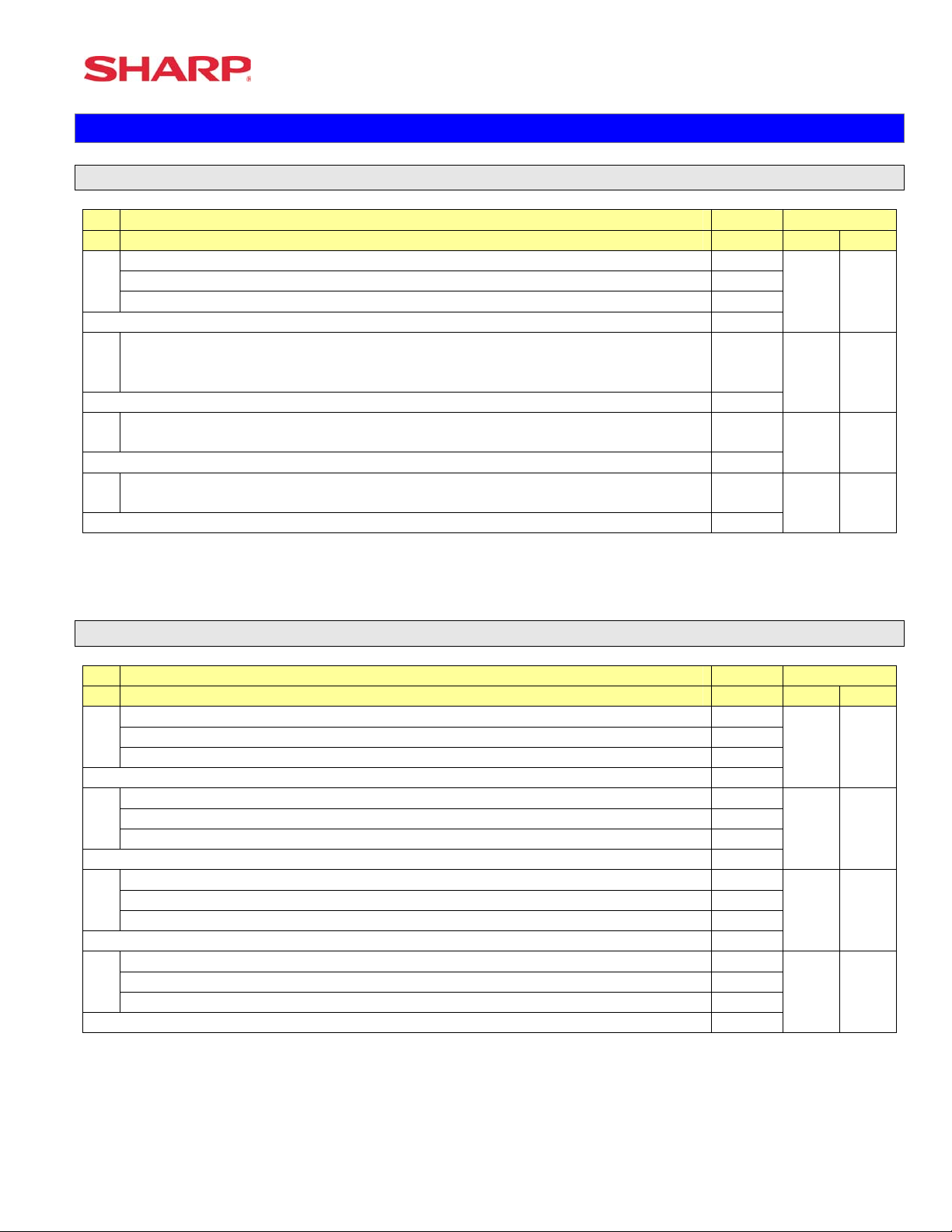
Procedure:
Enter the SRV-mode as previously outlined.
① Enter 971 → [ . ]
② Depress [@/FOR] key.
③ Enter the File Group number you want to allocate.
④ Depress [@/FOR] key.
⑤ Enter the value for the File Group.
⑥ If it is File Group type 2, depress [@/FOR] key, enter the number for data.
⑦ Depress the [CA/AT] key.
File Group Table
Group
FILE NAME TYPE File table No. (Create, Change the number of records or Erase/Change the number of records or Erase)
No.
1 Dept 1 01, 02, 03, 05, 06
2 Dept TEXT (8) 0 03
3 Dept TEXT (16) 0 04
4 PLU/UPC 1 08, 09, 10, 12, 18, 20, 22
5 PLU/UPC PRICE 1 0 10, 20, 22, /21, 23
6 PLU/UPC PRICE 1-6 0 11, 24, 26, /25, 27
7 PLU/UPC TEXT1 (8) 0 12
8 PLU/UPC TEXT1 (16) 0 13
9 PLU/UPC KP TEXT1 (12) 0 14
10 PLU/UPC TEXT1-6 (8) 0 15
11 PLU/UPC TEXT1-6 (16) 0 16
12 PLU/UPC KP TEXT1-6 (12) 0 17
13 PLU/UPC stock 0 19
14 DYNAMIC UPC 1 28, 29, 30, 33, 34, 38, 39, 41
15 DYNAMIC UPC PRICE 1 0 30, 39, 41, /40, 42
16 DYNAMIC UPC PRICE 1-6 0 31, 43, 45, /44, 46
17 DYNAMIC UPC TEXT1 (8) 0 32
18 DYNAMIC UPC TEXT1 (16) 0 33
19 DYNAMIC UPC KP TEXT1 (12) 0 34
20 DYNAMIC UPC TEXT1-6 (8) 0 35
21 DYNAMIC UPC TEXT1-6 (16) 0 36
22 DYNAMIC UPC KP TEXT1-6 (12) 0 37
23 UPC PGM PICK UP 1 47
24 DYNAMIC UPC PGM PICK UP 1 48
25 UPC X/Z PICK UP 1 49
Specifications subject to change without notice: Revision date 06/05 Page 43 of 266
Page 50

ER-A520/A530 Dealer Knowledge Book
Group
FILE NAME TYPE File table No. (Create, Change the number of records or Erase/Change the number of records or Erase)
No.
26 DYNAMIC UPC X/Z PICK UP 1 50
27 Link PLU 1 51
28 Set PLU 1 52
29 Condiment table 1 53, 79
30 Mix&Match Table 1 54, 55
31 SERVER 1 59, 60, 61, 62, 63, /64, 74, 81, 82
32 Reg buffer 1 69, 70, 71, 72, /79, 73, 74, 81, 82
33 Overlapped Server 0 74, 81, 82
34 GLU/PBLU 2 75, 80
35 Closed GLU 1 76, 77
36 AUTO GLU Generate code 1 78
37 KP BUFFER 0 73
38 BS/BT buffer 0 72
39 Term Dept 0 07
40 Term PLU/UPC 0 21, 23
41 Term Transaction 0 58
42 Term SERVER 0 64
43 Term DYNAMIC UPC 0 40, 42
44 All of term file 0 07, 21, 23, 40, 42, 58, 64
Type 0: Create/Erase only
Type 1: Create/Erase and Increase/Decrease the number of records.
Type 2: Create/Erase and Increase/Decrease the number of records for label and data individually.
Note: All memories are shared in the fixed RAM area.
Page 44 of 266 Specifications subject to change without notice: Revision date 06/05
Page 51

File Allocation
FILE TABLE
Note: This table can be used to calculate the memory allocation size. Its information is not printed
on FILE READING REPORT.
File
No.
01 DEPT PRESET 20 99 1 1 3 8
02 PRICE 20 99 (1) 1 1 0 3
03 TEXT (8 chara) 0 99 (1) 1 1 0 8
04 TEXT (16 chara) 20 99 (1) 1 1 0 16
05 CVM CHARACTER 20 99 (1) 1 1 0 1
06 DAILY 20 99 (1) 1 1 0 13
07 TERM 20 99 (1) 1 1 0 13
08 PLU/UPC PRESET 1000 ***** 1 1 9 15
09 FLAG 1000 ***** (8) 1 1 0 3
10 PRICE1 1000 ***** (8) 1 1 0 3
11 PRICE1-6 0 ***** (8) 1 1 0 18
12 TEXT1 (8 chara) 0 ***** (8) 1 1 0 8
13 TEXT1 (16 chara) 1000 ***** (8) 1 1 0 16
14 KP TEXT1 (12 chara) 1000 ***** (8) 1 1 0 12
15 TEXT1-6 (8 chara) 0 ***** (8) 1 1 0 48
16 TEXT1-6 (16 chara) 0 ***** (8) 1 1 0 96
17 KP TEXT1-6 (12 chara) 0 ***** (8) 1 1 0 72
18 CVM CHARACTER 1000 ***** (8) 1 1 0 1
19 STOCK 0 ***** (8) 1 1 0 4
20 DAILY (Price1) 1000 ***** (8) 1 1 0 9
21 TERM (Price1) 0 ***** (8) 1 1 0 9
22 WASTE DAILY (Price1) 1000 ***** (8) 1 1 0 9
23 WASTE TERM (Price1) 0 ***** (8) 1 1 0 9
24 DAILY (Price1-6) 0 ***** (8) 6 6 0 9
25 TERM (Price1-6) 0 ***** (8) 6 6 0 9
26 WASTE DAILY (Price1-6) 0 (8) ***** 6 6 0 9
27 WASTE TERM (Price1-6) 0 ***** (8) 6 6 0 9
28 DYNAMIC UPC PRESET 0 1 1 ***** 9 13
FLAG 0 ***** (28) 1 1
29 0 3
30 PRICE1 0 ***** (28) 1 1 0 3
31 PRICE1-6 0 0 ***** (28) 1 1 18
32 TEXT1 (8 chara) 0 ***** (28) 1 1 0 8
33 TEXT1 (16 chara) 0 ***** (28) 1 1 0 16
34 KP TEXT1 (12 chara) 0 ***** (28) 1 1 0 12
35 TEXT1-6 (8 chara) 0 ***** (28) 0 48 1 1
36 TEXT1-6 (16 chara) 0 ***** (28) 1 1 0 96
KP TEXT1-6 (12 chara) 0 ***** (28) 1 1 72
37 0
38 CVM CHARACTER 0 1 ***** (28) 1 1 0
39 DAILY (Price1) 0 ***** (28) 1 9 1 0
NAME
(MRS) (MAX) #1
RECORD BLOCK
(MRS) (MA
X)
#2
Label
Size
Data Size
Specifications subject to change without notice: Revision date 06/05 Page 45 of 266
Page 52

ER-A520/A530 Dealer Knowledge Book
File
No.
TERM (Price1) ***** 1 1 0 9
40 0 (28)
41 WASTE DAILY (Price1) (28) 1 1
42 WASTE TERM (Price1) 1 1 0 ***** (28) 0 9
43 DAILY (Price1-6) 0 ***** (28) 6 6 0 9
44 TERM (Price1-6) 0 ***** (28) 6 6 0 9
45 WASTE DAILY (Price1-6) ***** (28) 0 9 0 6 6
46 WASTE TERM (Price1-6) 0 ***** (28) 6 6 0 9
47
UPC PGM PICK UP
DYNAMIC UPC PGM
48
PICK UP
49 UPC X/Z PICK UP 100 100 1 0 1 9
DYNAMIC UPC X/Z PICK
50
UP
51 LINK PLU 10 ***** 1 1 9 35
52 SET PLU 10 ***** 1 1 9 70
53 Condiment Table 10 99 1 1 3 107
54 MIX & MATCH TABLE 10 99 1 1 3 4
55 MIX & MATCH SOLD 10 99 (54) 1 1 0 5
56 TRANSACTION LABEL 169 4
57 DAILY 169 9 169 (56) 1 1 0
58 TERM 169 169 9 (56) 1 1 0
59 SERVER PRESET 20 20 0 1 1 3 10
60 FLAG 20 20 (59) 1 1 0 1
61 TEXT 20 20 (59) 1 1 0 8
62 SERVER TRNS. LABEL 113 20 (59) 0 113 0 20 4
63 20 9
DAILY 20 (59) 0 113 113 (62)
64 TERM 113 113 (62) 20 20 (59) 9 0
65 113 0 1 1 4 0
RESET SERVER LABEL 113
66 TOTAL 113 113 0 9 (65) 1 1
67 TOTAL SERVER LABEL 113
TOTAL 113 113 (67) 0 9
68 1 1
69
REG BUFFER
70 (Reserved) 0 0 1 0 48 0 1
71 GLU/PBLU BUFFER 250 250 0 1 0 48 1
72 B.T. BUFFER 250 250 0 1 0 1 48
73 KP BUFFER 0 250 0 1 1 0 52
74 OVERLAPPED SERVER 0 250 0 0 20 (59) 0 48
GLU/PBLU
75 10-1000
76 CLOSED GLU 0 ***** 0 1 1 4 146
CLOSED GLU AMOUNT ***** (76) 1 0 125
77 0 1
78 AUTO GLU Generate Code 11 11 0 2 1 1 0
CONDIMENT EDIT
79
BUFFER
80 OPEN GLU BUFFER 250 250 0 1 1 6 10
NAME
(MRS) (MAX) #1
RECORD BLOCK
(MRS) (MA
0 ***** 0 9
100 100 1 0
0 100 1 1 9 0
0 100 1 9 0
169 1 1 0
113 0 1 1 4 0
250 250 0 1 0 48
*********
250 250 0 1 1 0 48
0 1 1 4 43
1
1
X)
1 9
#2
Label
Size
Data Size
Page 46 of 266 Specifications subject to change without notice: Revision date 06/05
Page 53

File Allocation
File
No.
OVERLAPPED
81
GLU/PBLU BUFFER
OVERLAPPED
82
MIX&MATCH BUFFER
83 FUNCTION TEXT 289 289 0 1 1 4 8
NAME
(MRS) (MAX) #1
RECORD BLOCK
0 250 0 0 20 (59) 0 48
0 250 0 0 20 (59) 0 5
(#1): Same as the number of record of table no.
(#2): Same as the number of block of table no.
(MRS) (MA
X)
#2
Label
Size
Data Size
Specifications subject to change without notice: Revision date 06/05 Page 47 of 266
Page 54

ER-A520/A530 Dealer Knowledge Book
N O T E S
Page 48 of 266 Specifications subject to change without notice: Revision date 06/05
Page 55

Section-4: PERIPHERALS
Page 56

Page 57

PERIPHERALS
Overview – Cable & Communications Specifications
RS-232 connections are simple, universal and a supported data interface for the ER-A520 and
ER-A530 model ECRs. The standards for communications of 256kbps or less and line lengths of
15m (50 ft) or less will depend on the length and quality of the cable.
1. Specifications:
(1) Cable: 24 – 28 AWG, Shielded, twisted pair – (refer to the chart on the next page)
(2) Connector: D – Sub 9 pin (female type) connector.
(3) Baud Rate: (Please refer to each peripheral’s section)
2. Pin Outs:
(Please refer to each peripheral’s section.)
COM-1
COM-2
Specifications subject to change without notice: Revision date 06/05 Page 51 of 266
Page 58

ER-A520/A530 Dealer Knowledge Book
3. ECR Pin Outs:
The DB-9 of the ER-A520 and ER-A530 follows EIA computer specifications for its pin outs as
shown below:
4. Belden Cable Chart:
The chart below is the specs for a Belden cable that can be used for communications.
RS232 Serial Cable
Maximum Distance from POS to Printer 50 ft. or less
Type Cable Twisted Pair
Wire Gauge
24 AWG / Shielded
Belden Number 9540
5. Cable Chart/Distances:
Typically, the recommended cabling distance length will be less than 25 feet when the data rate is
9600 bps or greater. If transmission errors occur, follow these procedures to determine the cause
of the problem:
1) Reduce the baud rate – when the preset is available.
2) Reduce the cable length – when the baud rate is fixed.
3) Use a cable with a lower capacitance per foot rating.
Page 52 of 266 Specifications subject to change without notice: Revision date 06/05
Page 59

Section – 1: Coin Dispenser
The following table shows the related PGM-Mode Job#s available for the ER-A520 and ER-A530
model ECRs when the Coin Dispenser is connected.
Scale
Mode Job# Description
2690 Channel Assignment
PGM-Mode
Note: The Telequip Transact coin dispenser (sales item ER-COIN) includes the necessary
connection cable as standard equipment.
2510 Cashier Drawer Assignment
PERIPHERALS
Specifications subject to change without notice: Revision date 06/05 Page 53 of 266
Page 60

ER-A520/A530 Dealer Knowledge Book
1. Cabling Pin Outs:
ER-A520/A530
UP-3301
D-SUB 9 (Female)
D-SUB 9 (Female)
TeleQuip Coin
FG
RXD
TXD
DTR
S.G
DSR
RTS
CTS
CI
1
2
3
4
5
6
7
8
9
1
3
2
4
5
2. Data Transmission:
- 7 bits ASCII code
- One Start bit
- Even Parity
- One Stop bit
- Baud Rate: 9600 bps (fixed)
3. Protocol
(ECR) (Coin)
EOT
“C”
<STX>XX<ETX><CC>
STATUS ACK
or
STATUS NAK
XX: Ten’s + ones
CC: Cents
TXD
RXD
GND
Page 54 of 266 Specifications subject to change without notice: Revision date 06/05
Page 61

PERIPHERALS
RS-232C Channel Assignment
ER-A520/530 is equipped with two RS-232C interfaces. If you use the communication functions,
the channel number of each RS-232C interface must be programmed by using the following
procedure.
Key Sequence:
To assign channel number to the peripherals, please follow the sequence below:
0
2690
@/FOR.
X
@/FOR
To program any function no.
ABCD
SBTL
CA/AT
X = 1
Item Description Entry
A Channel number for on-
line communication
Not connected 0
Standard channel 1 1
Selection
Standard channel 2 2
B Channel number for print
data sending (CVM)
Not connected 0
Standard channel 1 1
Standard channel 2 2
Not connected
0 C Channel number for scale
Standard channel 1 1
Standard channel 2 2
Channel number for the
coin dispenser
Not connected D
Standard channel 1 1
0
Standard channel 2 2
NOTE:
1. MRS = 0000
2. Data backup function always uses standard channel 2.
Specifications subject to change without notice: Revision date 06/05 Page 55 of 266
Page 62

ER-A520/A530 Dealer Knowledge Book
X = 2
NOTE:
MRS = 0000
Item Selection Entry
A Channel number for the
barcode reader
Description
Not connected 0
Standard channel 1 1
Standard channel 2 2
B Channel number the
remote printer 1
Not connected 0
Standard channel 1 1
Standard channel 2 2
C Channel number for the
remote printer 2
Not connected 0
Standard channel 1 1
Standard channel 2 2
D Always enter 0 0
X = 3
NOTE:
MRS = 0000
Item
Description Selection Entry
A Always enter 0 0
B
Channel number for the
slip printer TM-295
Not connected for
internal printer (printing
bills on receipt)
Standard channel 1 1
Standard channel 2 2
C
D Channel number for CAT
Always enter 0 0
Not connected 0
Standard channel 1
0
1
2 Standard channel 2
Page 56 of 266 Specifications subject to change without notice: Revision date 06/05
Page 63

PERIPHERALS
Procedure:
Enter the PGM2-Mode as previously outlined
1. Enter 2690
2. Depress [
.] key
3. Depress [@/FOR] key
4. Enter 1
5. Depress [@/FOR] key
6. Enter assigned channel numbers ( 4 digits)
7. Depress [SBTL] key
8. Depress the [CA/AT] key
Channel Assignment for COIN DISPENSER:
Quick Steps – Coin Dispenser
To quickly setup the ER-A520/ER-A530 to interface with a coin dispenser, please refer to the
outlined procedures below:
No. Description Comments/Procedure
Step–1 Connect the Coin Dispenser CH–1 or CH–2
Step–2
Step–3
Step–4 PGM Job#2510 Verify that the Cashiers have a valid Drawer Assignment (1 or 2)
PGM Job#2690
Program Reset
2690 Æ [.] Æ [@] Æ 1 Æ @ Æ 0001 [SBTL] Æ [CA/AT] for CH–1)
or
2690 Æ [.] Æ [@] Æ 1 Æ @ Æ 0002 [SBTL] Æ [CA/AT] for CH–2)
Note: Mu
• Place the SRV-Key counter-clockwise to 6 o’clock position
• Count 5 seconds
• Turn SRV-Key clockwise to 7o’clock position (SRV position)
• Verify”***PROGRAM RESET has printed on the journal-side
st match the physical connection
(SRV’ position)
tape.
Specifications subject to change without notice: Revision date 06/05 Page 57 of 266
Page 64

ER-A520/A530 Dealer Knowledge Book
Section–2: Scale
The following table shows the related SRV and PGM-Mode Job#s available for the ER-A520 and
ER-A530 model ECRs when the Scale is connected.
Scale
Mode Job# Description
SRV-Mode
PGM-Mode
903–B Symbol of Scale Entry
903–C Unit of Weight for Scale Entries
906–D
918–B
950
2690
2110
2210 PLU Function Programming
2231 PLU Function Range Programming
2618
Fractional Quantities Entries
Fractional Entries for Non-Scalable
Dept./PLU Items
[SCALE] – Function #107
(OPEN TARE] – Function #108
Channel Assignment
Dept. Function Programming
Scale Tare Table Programming
Page 58 of 266 Specifications subject to change without notice: Revision date 06/05
Page 65

1, Cabling Pin Outs:
ER-A520/A530
UP-3301
D-SUB 9 (Female)
D-SUB 9 (Female)
PERIPHERALS
Avery/NCI/Weightronix
D-SUB 9 (Female)
FG
RXD
TXD
DTR
S.G
DSR
RTS
CTS
CI
1
2
3
4
5
6
7
8
9
3
2
5
TXD
RXD
GND
2. Data Transmission:
- Bits ASCII Code
- Even Parity
- One Stop Bit
- Baud Rate: 9600 bps (fixed)
3. Protocol:
(ECR) (Scale)
COMM
AND
RESPONSE
<STX>0XX.XX<CR>;LB
<Command> <Response>
W
<STX>0XX.XX<CR>;KG
(Error)
<STX>Status byte><CR>
B7
Parity Bit
B6
Always
=
B5
Net Wt.
=
B4
Center
Of Zero
=
B3
Outside
Of Zero
=
B2
Under
Zero
=
B1
Out Of
Range
=
B0
Motion
=
Specifications subject to change without notice: Revision date 06/05 Page 59 of 266
Page 66

ER-A520/A530 Dealer Knowledge Book
RS-232C Channel Assignment
Key Sequence:
To assign channel number to the peripherals, please follow the sequence below:
0
2690
@/FOR.
X
@/FOR
To program any function no.
ABCD
SBTL
CA/AT
X = 1
Item Description Selection
A Channel number for on-
line communication
Not connected 0
Standard channel 1 1
Entry
Standard channel 2 2
B Channel number for print
data sending (CVM)
Not connected 0
Standard channel 1 1
2 Standard channel 2
C Channel number for scale
Not connected 0
Standard channel 1 1
Standard channel 2 2
D Channel number for the
coin dispenser
Not connected 0
Standard channel 1 1
Standard channel 2 2
NOTE:
1. MRS = 0000
2. Data backup function always uses standard channel 2.
Page 60 of 266 Specifications subject to change without notice: Revision date 06/05
Page 67

X = 2
PERIPHERALS
NOTE:
MRS = 0000
Item Selection Entry
A Channel number for the
barcode reader
B Channel number the
remote printer 1
remote printer 2
D Always enter 0
Description
Not connected 0
Standard channel 1 1
Standard channel 2 2
Not connected 0
Standard channel 1 1
Standard channel 2 2
Not connected 0 C Channel number for the
Standard channel 1 1
Standard channel 2 2
0
NOTE:
MRS = 0000
X = 3
Item Description Selection Entry
A Always enter 0 0
B Channel number for the
slip printer TM-295
C Always enter 0 0
D Channel number for CAT
Not connected for
internal printer (printing
bills on receipt)
Standard channel 1 1
Standard channel 2 2
Not connected 0
Standard channel 1 1
Standard channel 2 2
0
Specifications subject to change without notice: Revision date 06/05 Page 61 of 266
Page 68

ER-A520/A530 Dealer Knowledge Book
Procedure:
Enter the PGM2-Mode as previously outlined
1. Enter 2690
2. Depress [
3. Depress [@/FOR] key
4. Enter 1
5. Depress [@/FOR] key
6. Enter assigned channel numbers ( 4 digits)
7. Depress [SBTL] key
8. Depress the [CA/AT] key
Channel Assignment for SCALE:
2690
.] key
.
@/FOR
1
@/FOR
0010
or
0020
SBTL
CA/AT
Page 62 of 266 Specifications subject to change without notice: Revision date 06/05
Page 69

PERIPHERALS
Quick Steps – Scale
To quickly setup the ER-A520/ER-A530 to interface with a Scale, please refer to the outlined
procedures below:
No. Description Comments/Procedure
Step–1 Connect the Scale CH–1 or CH–2
Step–2 SRV Job#903-B, C, D
Step–3 SRV Job#906-D 906 Æ [.] Æ [@] Æ xxx1 Æ [CA/AT]
Step–4
Step-5
Step-6
Step-7
Step-8
SRV Job#918
SRV Job#950
PGM Job #2690
Program Reset
PGM Job #2110
-and/orPGM Job#2210
903 Æ [.] Æ [@] Æ x030 Æ [CA/AT]
(For 3 Decimal Places) or
903 Æ [.] Æ [@] Æ x020 Æ [CA/AT]
(For 2 Decimal Places)
(For Fractional Entries)
918 Æ [.] Æ [@] Æ x0xx Æ [CA/AT]
(For Non-Scale Fractional Entries) or
918 Æ [.] Æ [@] Æ x1xx Æ [CA/AT]
(For Disallowing Non-Scale Fractional Entries)
• Place the [SCALE] Key (Function #107) on the keyboard
• Place the [OPEN TARE] Key (Function #108) on the keyboard
2690 Æ [.] Æ [@] Æ 1 Æ @ Æ 0010 [SBTL] Æ [CA/AT] for CH–1)
or
2690 Æ [.] Æ [@] Æ 1 Æ @ Æ 0020 [SBTL] Æ [CA/AT] for CH–2)
Note: Must match the physical connection
• Place the SRV-Key counter-clockwise to 6 o’clock position
(SRV’ position)
• Count 5 seconds
• Turn SRV-Key clockwise to 7o’clock position (SRV position)
• Verify”***PROGRAM RESET has printed on the journal-side
tape.
2110 Æ [.] Æ [@] Æ (Dept. No.) Æ @ Æ xyzxxx [SBTL] Æ [CA/AT]
–and/or-
2210 Æ [.] Æ [@] Æ (Dept. No.) Æ @ Æ xyz [SBTL] Æ [CA/AT]
Y = Tare Table No. (1–9)
Z = Scale Comp. /Enabled/Inhibited = 2/1/0
Specifications subject to change without notice: Revision date 06/05 Page 63 of 266
Page 70

ER-A520/A530 Dealer Knowledge Book
Section–3: Slip Printer
The following table shows the related SRV and PGM-Mode Job#s available for the ER-A520 and
ER-A530 ECRs when the Slip Printer is connected.
Slip Printer
Mode Job# Description
SRV-Mode
PGM-Mode
913–B
920-A Combine like items for GLU items printed a bill
921-C Bill Printing Method
928–A Printing of Slip Logo
928–B
928–C
928–D
950
2690 Channel Assignment
2320 Media Key Function Programming
2615 Validation Limitation Programming
Escape Compulsory SLIP & Validation
Val. Message Printing on Slip
Header Line Printing on Slip when Reorder Printing
Print PLU Items on Slip when $0.00
Set PLU Items Print on Slip
PB/NBAL Prints on Slip
Slip Print Compulsion System
[PRINT]–Function #43
[SLIP]–Function #44
Page 64 of 266 Specifications subject to change without notice: Revision date 06/05
Page 71

PERIPHERALS
Specifications subject to change without notice: Revision date 06/05 Page 65 of 266
Page 72

ER-A520/A530 Dealer Knowledge Book
1. Cabling Pin Outs:
9-Pin D–Sub 25-Pin D–Sub
2. Data Transmission:
- 8 Bits ASCII Code
- No Start Bit
- Non Parity
- 1 Stop Bit
- Baud Rate: 9600 bps (fixed)
*Handshaking: DTR/DSR Control
ECR SLIP PRINTER
Page 66 of 266 Specifications subject to change without notice: Revision date 06/05
Page 73

TM-U295 Switch–1Settings:
Switch Contents On Off
SW1-1 Data Receive Buffer Ignored Prints “?” OFF
SW1-2 Receive Buffer Capacity 35 bytes 512 Kbytes OFF
SW1-3 Handshaking XON/XOFF DTR/DSR OFF
SW1-4 Data Word length 7 bits 8 bits OFF
SW1-5 Parity Check With Parity Without Parity OFF
SW1-6 OFF
SW1-7 Baud Rate Selection (*1) OFF
SW1-8 Baud Rate Selection (*1) OFF
SW1-9 DSR (#6) Reset Effective Invalid OFF
SW-10 Init (#25) Reset Effective Invalid ON
(*1): SW1-7, 1-8 Definitions
Parity selection Even Parity Odd Parity
1200 bps ON ON
2400 bps OFF ON
4800 bps ON OFF
9600 bps OFF OFF
PERIPHERALS
ROM Version 1.08
Setting
Rate SW1-7 SW1-8
Specifications subject to change without notice: Revision date 06/05 Page 67 of 266
Page 74

ER-A520/A530 Dealer Knowledge Book
RS-232C Channel Assignment
Key Sequence:
To assign channel number to the peripherals, please follow the sequence below:
0
2690
@/FOR.
X
@/FOR
To program any function no.
ABCD
SBTL
CA/AT
X = 1
Item Description Selection Entry
A Channel number for on-
line communication
Not connected
Standard channel 1
0
1
Standard channel 2 2
B Channel number for print
data sending (CVM)
Not connected 0
Standard channel 1 1
Standard channel 2 2
C Channel number for scale
Not connected 0
Standard channel 1 1
Standard channel 2 2
D Channel number for the
coin dispenser
Not connected 0
Standard channel 1 1
Standard channel 2 2
NOTE:
1. MRS = 0000
2. Data backup function always uses standard channel 2.
Page 68 of 266 Specifications subject to change without notice: Revision date 06/05
Page 75

X = 2
Item Description Selection Entry
PERIPHERALS
NOTE:
MRS = 0000
X = 3
A Channel number for the
barcode reader
B Channel number the
remote printer 1
C Channel number for the
remote printer 2
D
Always enter 0 0
Not connected 0
Standard channel 1 1
Standard channel 2 2
Not connected 0
Standard channel 1
Standard channel 2 2
Not connected 0
Standard channel 1 1
Standard channel 2 2
1
NOTE:
MRS = 0000
Procedure:
Item Description Selection Entry
A Always enter 0 0
B Channel number for the
slip printer TM-295
C Always enter 0 0
D Channel number for CAT
Not connected for
internal printer (printing
bills on receipt)
Standard channel 1 1
Standard channel 2 2
Not connected 0
Standard channel 1 1
Standard channel 2 2
0
Specifications subject to change without notice: Revision date 06/05 Page 69 of 266
Page 76

ER-A520/A530 Dealer Knowledge Book
Enter the PGM2-Mode as previously outlined
1. Enter 2690
2. Depress [
3. Depress [@/FOR] key
4. Enter 3
5. Depress [@/FOR] key
6. Enter assigned channel numbers ( 4 digits)
7. Depress [SBTL] key
8. Depress the [CA/AT] key
Channel Assignment for SLIP PRINTER:
.] key
Page 70 of 266 Specifications subject to change without notice: Revision date 06/05
Page 77

PERIPHERALS
Quick Steps – Slip Printer
To quickly setup the ER-A520/ER-A530 to interface with an Epson TM-U295 Slip Printer, please
refer to the outlined procedures below:
No. Description Comments/Procedures
Step–1 Connect the Slip Printer CH–1 or CH–2
Step–2 SRV Job#913-B
Step–3 SRV Job#928- A, B, C, D
Step-4 SRV Job#950
Step-5
Step-6
Step-7
PGM Job #2690
Program Reset
PGM Job #2615
913 Æ [.] Æ [@] Æ x1xx Æ [CA/AT]
(For Escaping Compulsory Slip or Validation) or
913 Æ [.] Æ [@] Æ x0xx Æ [CA/AT]
(For No Escape of Compulsory Slip or Validation)
928 Æ [.] Æ [@] Æ ABCD Æ [CA/AT]
A: Slip Logo Text Prints Yes/No = 1/0
B: VP Message Prints on Slip Yes/No = 2/0
B: C: Header Line on Slip Prints Reorder No/Yes = 1/0
C: Prints $0.00 PLU Items on Slip No/Yes = 4/0
C: Prints PLU Text of Set PLU Links on Slip No/Yes = 2/0
D: Print the PB/NBAL on Slip No/Yes = 4/0
D: Compulsory Slip System PBLU Only/Every Trans/By Media
Yes/No = 2/1/0
• Place the [SLIP] Key (Function #44) on the keyboard
• Place the [PRINT (Validation)] Key (Function #43) on the
keyboard
2690 Æ [.] Æ [@] Æ 3 Æ @ Æ 0100 [SBTL] Æ [CA/AT] for CH–1)
or
2690 Æ [.] Æ [@] Æ 3 Æ @ Æ 0200 [SBTL] Æ [CA/AT] for CH–2)
Note: Must match the physical connection
• Place the SRV-Key counter-clockwise to 6 o’clock position
(SRV’ position)
• Count 5 seconds
• Turn SRV-Key clockwise to 7o’clock position (SRV position)
• Verify”***PROGRAM RESET has printed on the journal-side
tape.
2615 Æ [.] Æ [@] Æ VVXXAB Æ [SBTL] Æ [CA/AT]-
VV: Initial Line Feed
XX: Max Slip Line No.
A: No. of Times for Validation when set for Compulsory = 0–9
B: No. Line Feed after Tray SBTL key is depressed = 0–9
Specifications subject to change without notice: Revision date 06/05 Page 71 of 266
Page 78

ER-A520/A530 Dealer Knowledge Book
Section–4: Remote Kitchen Printer
The following table shows the related SRV and PGM-Mode Job#s available for the ER-A520 and
ER-A530 ECRs when a Remote Printer is connected.
Remote Kitchen Printer
Mode Job# Description
SRV-Mode
PGM-Mode
918–A Output of Set PLU to KP
918–B Red Color Print on KP when PLU/UPC’s are ZERO price
items
918–C Like Items Consolidation on KP
918–C
926–A Sending Direct VOID and Past Item VOID Data to the KP
926-B Sending Refund Data to the KP
929-A KP Print Format when Finalizing (Expediter Print Format)
950
971
971 #37 KP Buffer
2690 Channel Assignment
2692
3653 Back Up Kitchen Printer Programming
3654 Kitchen Printer Name Programming
3655 Kitchen Printer Print Format Programming
3656 Chit Receipt Print Format Programming
2118 Department KP Print Assignment Programming
2218
2328
Dept/PLU and UPC (EAN) Text Print on KP in Double
Size Character
[RP Send]–Function #114
# 9 KP Text 1 (12)/ #12 KP Text 1-6 (12) – Optional. If
not allocated the PLU description will be used.
Kitchen Printer Programming
PLU/UPC KP Print Assignment Programming
Media Key Print Assignment Programming
Page 72 of 266 Specifications subject to change without notice: Revision date 06/05
Page 79

1. Cabling Pin Outs:
9-Pin D–Sub 25-Pin D–Sub
ECR EPSON PRINTER
PERIPHERALS
2. Data Transmission:
- 8 Bits ASCII Code
- No Start Bit
- Non Parity
- 1 Stop Bit
- Baud Rate: 9600 bps (fixed)
*Handshaking: DTR/DSR Control
Specifications subject to change without notice: Revision date 06/05 Page 73 of 266
Page 80

ER-A520/A530 Dealer Knowledge Book
Kitchen Printer Programming - 2692
X: KP No. KP2/KP1 = 2/1
A: Logo Text Print Yes/No = 1/0
B: Auto Cut Yes/No = 1/0
C: Type of Printer
TM-T88III+Logo/TM-T88III/TM-U230/TM-U220 = 3/2/1/0
Back Up Kitchen Printer Programming - 3653
X: KP No. KP2/KP1 = 2/1
nd
Y: 2
KP (Back Up) KP2/KP1/Nothing =2/1/0
MRS = 0
Page 74 of 266 Specifications subject to change without notice: Revision date 06/05
Page 81

Kitchen Printer Name Programming - 3654
X: KP No. KP2/KP1 = 2/1
KP Name: Maximum 12 Characters
Characters can be entered by using the character keys or by character code entry. The key
sequence for entering character codes is as follows:
XXX Æ [00] key XXX: Character Code (3 digits)
MRS = Spaces
PERIPHERALS
Specifications subject to change without notice: Revision date 06/05 Page 75 of 266
Page 82

ER-A520/A530 Dealer Knowledge Book
Kitchen Printer Print Format Programming - 3655
X: KP No. KP2/KP1 = 2/1
A: Taxable Status Print Yes/No =1/0
B: Qty Print when Qty is “1” Yes/No =1/0
C: Dept /PLU/UPC (EAN) Code Print Yes/No =1/0
D: Unit Price Print Yes/No =1/0
E: Total Amount Print Yes/No =1/0
MRS = 00000
Note: [Taxable Status Print] = “YES” is effective when [AMOUNT] Print = “YES”
Page 76 of 266 Specifications subject to change without notice: Revision date 06/05
Page 83

Chit Receipt Format Programming - 3656
A: Taxable Status Print Yes/No =1/0
B: Qty Print when Qty is “1” Yes/No =1/0
C: Dept /PLU/UPC (EAN) Code Print Yes/No =1/0
D: Unit Price Print Yes/No =1/0
E: Total Amount Print Yes/No =1/0
MRS = 00000
Note: [Taxable Status Print] = “YES” is effective when [AMOUNT] Print = “YES”
PERIPHERALS
Specifications subject to change without notice: Revision date 06/05 Page 77 of 266
Page 84

ER-A520/A530 Dealer Knowledge Book
RS-232C Channel Assignment
Key Sequence:
To assign channel number to the peripherals, please follow the sequence below:
0
2690
@/FOR.
X
@/FOR
To program any function no.
ABCD
SBTL
CA/AT
X = 1
Item Description Selection Entry
A Channel number for on-
line communication
Not connected 0
Standard channel 1 1
Standard channel 2 2
B Channel number for print
data sending (CVM)
Not connected 0
Standard channel 1 1
Standard channel 2 2
C Channel number for scale
Not connected 0
Standard channel 1 1
Standard channel 2 2
D Channel number for the
coin dispenser
Not connected
Standard channel 1 1
0
Standard channel 2 2
NOTE:
MRS = 0000
Page 78 of 266 Specifications subject to change without notice: Revision date 06/05
Page 85

X = 2
PERIPHERALS
NOTE:
MRS = 0000
Item Description Selection
A Channel number for the
barcode reader
B Channel number the
remote printer 1
C Channel number for the
remote printer 2
D Always enter 0 0
Not connected 0
Standard channel 1 1
Standard channel 2 2
Not connected 0
Standard channel 1 1
Standard channel 2 2
Not connected 0
Standard channel 1 1
Standard channel 2 2
Entry
NOTE:
MRS = 0000
X = 3
Item Description Selection Entry
A Always enter 0 0
B Channel number for the
slip printer TM-295
C Always enter 0 0
D Channel number for CAT
Not connected for
internal printer (printing
bills on receipt)
Standard channel 1 1
Standard channel 2 2
Not connected 0
Standard channel 1
Standard channel 2 2
0
1
Specifications subject to change without notice: Revision date 06/05 Page 79 of 266
Page 86

ER-A520/A530 Dealer Knowledge Book
r
Procedure:
Enter the PGM2-Mode as previously outlined
1. Enter 2690
2. Depress [
3. Depress [@/FOR] key
4. Enter 2
5. Depress [@/FOR] key
6. Enter assigned channel numbers ( 4 digits)
7. Depress [SBTL] key
8. Depress the [CA/AT] key
Channel Assignment for KP:
.] key
2690
.
@/FOR
2
@/FOR
1000(KP#1)
0
o
(KP#2)
0020
SBTL
CA/AT
Page 80 of 266 Specifications subject to change without notice: Revision date 06/05
Page 87

PERIPHERALS
Quick Steps – Remote Kitchen Printer
To quickly setup the ER-A520/ER-A530 to interface with a Remote Kitchen Printer, please refer to
the outlined procedures below:
No. Description Comments/Procedures
Step–1 Connect the Remote Printers KP#1 on CH–1 or KP#2 on CH–2
Step–2 SRV Job#918-A 918 Æ [.] Æ [@] Æ 4xxx Æ [CA/AT]
Output of Set PLU to KP
Step-3 SRV Job#918-B 918 Æ [.] Æ [@] Æ x2xx Æ [CA/AT]
Red Color Print on KP when PLU/UPC’s are ZERO price items
Step-4 SRV Job#918-C 918 Æ [.] Æ [@] Æ x0xx Æ [CA/AT]
Like Items Consolidation on KP
Step-5 SRV Job#918-C
Step-6 SRV Job#926-A 926 Æ [.] Æ [@] Æ 3xxx Æ [CA/AT]
Step–6 SRV Job#926-B 926 Æ [.] Æ [@] Æ x0xx Æ [CA/AT]
Step-7 SRV Job#929-A 926 Æ [.] Æ [@] Æ 1xxx Æ [CA/AT]
Step-8 SRV Job#950
Step-9 SRV Job#971 Create #37 KP Buffer
Step-10
Step-11
Step-12
Step-13
PGM Job #2690
PGM Job #2692
Program Reset
Other PGM2 Mode Programming
918 Æ [.] Æ [@] Æ x1xx Æ [CA/AT]
Dept/PLU and UPC (EAN) Text Print on KP in Double Size
Character
Sending Direct VOID and Past Item VOID Data to the KP
Sending Refund Data to the KP
Detail KP Print Format when Finalizing (Expediter Print Format)
• Place the [RP Send] Key (Function #114) on the keyboard if
required.
Note: The RP Send Key can send an item to the remote KP before
finalizing the transaction.
KP#1: 2690 Æ [.] Æ [@] Æ 2 Æ @ Æ 0100 [SBTL] Æ [CA/AT] for CH–1)
or
KP#2: 2690 Æ [.] Æ [@] Æ 2 Æ @ Æ 0020 [SBTL] Æ [CA/AT] for CH–2)
Note: Must match the physical connection
2692 Æ [.] Æ [@] Æ X Æ @ Æ ABC [SBTL] Æ [CA/AT]
X: KP No. KP2/KP1 =2/1
A: Logo Text Print Yes/No =1/0
B: Auto Cut Yes/No =1/0
C: Type of Printer
TM-T88III+Logo /TM-T88III/TM-U230/TM-U220 = 3/2/1/0
• Place the SRV-Key counter-clockwise to 6 o’clock position
(SRV’ position)
• Count 5 seconds
• Turn SRV-Key clockwise to 7o’clock position (SRV position)
• Verify”***PROGRAM RESET has printed on the journal-side
tape.
3653 Æ [.] Æ [@] Æ X Æ @ Æ Y Æ [SBTL] Æ [CA/AT]
X: KP No. KP2/KP1 = 2/1
Y: Back Up Printer KP2/KP1/Nothing = 2/1/0
3654Æ [.] Æ [@] Æ X Æ @ Æ Name (12 Max) Æ [SBTL] Æ [CA/AT
X: KP No. KP2/KP1 = 2/1
Characters can be entered by using the character keys or numeric
keys.
XXX Æ 00 Key XXX: Character Code (Digits)
Specifications subject to change without notice: Revision date 06/05 Page 81 of 266
Page 88

ER-A520/A530 Dealer Knowledge Book
Step-14
Other PGM2 Mode Programming
3655 Æ [.] Æ [@] Æ X Æ @ Æ ABCDE Æ [SBTL] Æ [CA/AT
X: KP No. KP2/KP1 = 2/1
A: Taxable Status Print Yes/No = 1/0
B: Qty Print when Oty is 1 Yes/No = 1/0
C: Dept/PLU/UPC(EAN) Code Print Yes/No = 1/0
D: Unit Price Print Yes/No = 1/0
E: Total Amount Print Yes/No = 1/0
MRS = 00000
3656 Æ [.] Æ [@ Æ ABCDE Æ [SBTL] Æ [CA/AT
Chit Receipt Format
A: Taxable Status Print Yes/No = 1/0
B: Qty Print when Oty is 1 Yes/No = 1/0
C: Dept/PLU/UPC (EAN) Code Print Yes/No = 1/0
D: Unit Price Print Yes/No = 1/0
E: Total Amount Print Yes/No = 1/0
MRS = 00000
Note: “TAXABLE STATUS Print = YES is effective when
“AMOUNT” print = YES
Page 82 of 266 Specifications subject to change without notice: Revision date 06/05
Page 89

Overview: Scanner (Barcode Reader)
The new ER-A520 and ER-A530 model ECRs are capable of scanning the following UPC (EAN)
codes.
1) UPC (EAN) Available Codes:
UPC-A (Number System Character 0,2,3,4,5)
0 * * * * * “ “ “ “ “ C/D
* Maker Code “Item Code
2 “ “ “ “ “ ‘ * * * * C/D
“Item Code ‘P/C-Price Check Digit *Price
Note: Maximum Price = $99.99
3 C/D
Use for National Drug Codes or National Health Retail Item Codes
4 * * * * * * * * * * C/D
*Free Format
* * C/D 5 * * ‘ ‘ ‘ “ “
*Maker Code ‘Family Code “Coupon Price
UPC-E
UPC-E is a zero-suppressed version of UPC-A that conforms to the UPS-E Standards.
EAN 13
* * “ “ “ “ “ ‘ ‘ ‘ ‘ ‘ C/D
*Nation Code “ Maker Code ‘Item Code
EAN-13 plus Add-On
* * “ “ “ “ ‘ ‘ C/D
*Nation Code “Maker Code ‘Item Code *Add On Codes (5 Digits)
*Nation Code “Maker Code ‘Item Code *Add On Codes (2 Digits)
“ ‘ ‘ ‘
‘ ‘ * * “ “ “ “ “ ‘ ‘ ‘ C/D
*****
**
PERIPHERALS
Specifications subject to change without notice: Revision date 06/05 Page 83 of 266
Page 90

ER-A520/A530 Dealer Knowledge Book
EAN8
Ordinary EAN-8 Codes
40 123 12 7
AB CDE FG H
AB: Nation Code
CDE: Maker Code
FG: Item Code
H: Check Digit
* * “ “ “ CD
*Nation Code “Maker Code ‘Item Code
Internal encoding using the EAN-8 Code (2x Code)
*Dept Code “Price
“ ‘
“ “ 2 * * “ “ CD
Page 84 of 266 Specifications subject to change without notice: Revision date 06/05
Page 91

PERIPHERALS
Section–5: Scanner (Barcode Reader)
The following table shows the related SRV and PGM-Mode Job#s available for the ER-A520 and
ER-A530 ECRs when the Scanner is connected.
Scanner (Barcode Reader)
Mode Job# Description
SRV-Mode
906-A
906-D
907-B UPC (EAN) Codes Printing on Receipt and Journal
907-C Enable Negative UPC
909-B Printing of UPC Data when Resetting
911-B C/D Check of UPC (EAN)
921-A Convert UPC-E Codes to UPC-A Codes
971
Stock Counter Availability Function
UPC Look Up at Refund Entry
File Groups 14-22, 23, 24 and 26 - Optional
Dynamic UPC also known as the UPC Learning Function,
allows you to register a UPC that has not been
programmed in the main PLU/UPC file. The UPC is
added to the Dynamic UPC file memory space, for
temporary storage or for a later upload to the main
PLU/UPC file. This can assist with the register traffic flow
and prevent unwanted and inaccurate items from being
added to the PLU/UPC file. At the end of day and after
verifying the UPCs and making any necessary edits, the
contents of the dynamic UPC file can be downloaded to
the main UPC file using the PGM 2099 job code.
If you do not allocate Dynamic UPC, the UPC Learning
Function is still available. The UPC will add directly to
the main PLU/UPC file. No upload required.
[DEPT#]-Function #106
[AMT]–Function #109
[REPEAT]-Function #110
[INQ]–Function #111
[NO DEL]-Function #112
[PRCHNG]-Function #113
ERA530 only Enable to allow Learning Function in REG
mode
PGM-Mode
950
2690 Channel Assignment
2691 Scanner Settings
1200 UPC (EAN) Programming
2616 - P10
Specifications subject to change without notice: Revision date 06/05 Page 85 of 266
Page 92

ER-A520/A530 Dealer Knowledge Book
1. Cabling Pin Outs:
MS6720 Scanner
DB9 Male
Sharp Register
DB9 Female
PGM2 Mode Related Programming - 2691
W: Data Bit 7bits / 8bits =1/0
X: Parity Bit Non / Odd / Even =2/1/0
Y: Stop Bit 1bit / 2bits =1/0
Z: Transmission Speed 19200bps / 9600bps / 4800bps =2/1/0
MRS = 1110
Page 86 of 266 Specifications subject to change without notice: Revision date 06/05
Page 93

2. Cable Requirements for other Metrologic Scanners
Note: The RS-232 cable must be labeled 53601A
with the ER-A520 and ER-A530 ECRs.
This cable MUST be specifically ordered with the scanner from your local distributor.
for the MS7120, MS9520 and MS9540 to work
PERIPHERALS
ERA520ERA520
Specifications subject to change without notice: Revision date 06/05 Page 87 of 266
Page 94

ER-A520/A530 Dealer Knowledge Book
Y
(4)
Metrologic MS6720 Scanner - Programming Requirements:
Scan the following in order from top to bottom.
ENTER PROGRAM MODE
RECALL DEFAULTS
(1)
(2)
PARITY = ODD
(3)
ENABLE RTS/CTS
DISABLE LINE FEED
(5)
4800 BAUD RATE
(6)
ENABLE STX PREFIX
(7)
ENABLE UPC PREFIX
(8)
Unplug the scanner power supply. Then re connect (power 0ff/on); This RESET is necessary
for the scanner to work properly.
our Scanner is now ready for use. You will have
to program the items you will be scanning into
the register.
Page 88 of 266 Specifications subject to change without notice: Revision date 06/05
Page 95

Metrologic MS7120 Scanner - Programming Requirements:
Scan the following in order from top to bottom.
PERIPHERALS
Note: if you are having trouble
scanning the bar codes, please refer
to your Metrologic manual.
Specifications subject to change without notice: Revision date 06/05 Page 89 of 266
Page 96

ER-A520/A530 Dealer Knowledge Book
Your scanner is now ready for use. You
will have to program the items you will be
scanning into the register.
Page 90 of 266 Specifications subject to change without notice: Revision date 06/05
Page 97

Metrologic MS9540 Scanner - Programming Requirements:
Scan the following in order from top to bottom.
PERIPHERALS
Your scanner is now ready for use. You
will have to program the items you will
be scanning into the register.
Specifications subject to change without notice: Revision date 06/05 Page 91 of 266
Page 98

ER-A520/A530 Dealer Knowledge Book
RS-232C Channel Assignment
Key Sequence:
To assign channel number to the peripherals, please follow the sequence below:
0
2690
@/FOR.
X
@/FOR
To program any function no.
ABCD
SBTL
CA/AT
X = 1
Item Entry
A Channel number for on-
line communication
Description Selection
Not connected 0
Standard channel 1 1
Standard channel 2 2
B Channel number for print
data sending (CVM)
Not connected 0
Standard channel 1 1
Standard channel 2 2
C
Channel number for scale
Not connected 0
Standard channel 1
1
Standard channel 2 2
D Channel number for the
coin dispenser
Not connected 0
Standard channel 1
1
Standard channel 2 2
NOTE:
1. MRS = 0000
2. Data backup function always uses standard channel 2.
Page 92 of 266 Specifications subject to change without notice: Revision date 06/05
Page 99

X = 2
Item Description Selection Entry
PERIPHERALS
NOTE:
MRS = 0000
A Channel number for the
barcode reader
B Channel number the
remote printer 1
C
D
X = 3
Channel number for the
remote printer 2
Always enter 0 0
Not connected 0
Standard channel 1 1
Standard channel 2 2
Not connected 0
Standard channel 1 1
Standard channel 2 2
Not connected 0
Standard channel 1
Standard channel 2
1
2
NOTE:
MRS = 0000
Item Description Selection Entry
A Always enter 0 0
B Channel number for the
slip printer TM-295
C Always enter 0 0
D Channel number for CAT
Not connected for
internal printer (printing
bills on receipt)
Standard channel 1
Standard channel 2 2
Not connected 0
Standard channel 1
Standard channel 2 2
0
1
1
Specifications subject to change without notice: Revision date 06/05 Page 93 of 266
Page 100

ER-A520/A530 Dealer Knowledge Book
Procedure:
Enter the PGM2-Mode as previously outlined
1. Enter 2690
2. Depress [
3. Depress [@/FOR] key
4. Enter 2
5. Depress [@/FOR] key
6. Enter assigned channel numbers ( 4 digits)
7. Depress [SBTL] key
8. Depress the [CA/AT] key
Channel Assignment for Scanner:
.] key
Page 94 of 266 Specifications subject to change without notice: Revision date 06/05
 Loading...