

Page 1
ELECTRONIC
CASH REGISTER
MODEL ER-A440
SRV Key : LKGIM7113RCZZ
PRINTER: DP730
(For "U" & "A" version)
CONTENTS
CHAPTER 1. GENERAL . . . . . . . . . . . . . . . . . . . . . . . . . . . . . . . . . . . . . . . . 1
CHAPTER 2. LIST OF OPTIONS . . . . . . . . . . . . . . . . . . . . . . . . . . . . . . . . . 2
CHAPTER 3. REMOVING THE TOP CABINET. . . . . . . . . . . . . . . . . . . . . . . 3
CHAPTER 4. REMOVING THE PRINTER UNIT . . . . . . . . . . . . . . . . . . . . . . 3
CHAPTER 5. REMOVING THE MAIN PWB . . . . . . . . . . . . . . . . . . . . . . . . . 4
CHAPTER 6. REMOTE DRAWER: ER-04DW. . . . . . . . . . . . . . . . . . . . . . . . 4
CHAPTER 7. EXPANSION RAM CHIP (ER-03RA). . . . . . . . . . . . . . . . . . . . 5
CHAPTER 8. JOURNAL NEAR END SENSOR: DUNTK3677BH03 . . . . . . . 5
CHAPTER 9. KEY TOP KIT: ER-11KT7/12KT7/22KT7/11DK7G/51DK7G . . 6
Parts marked with " " is importa nt for maintaining t he safety of the set . Be sure to replace thes e parts with specifi ed
ones for maintaining the safety and performance of the set.
SHARP CORPORATION
This document has bee n pu bl is hed to be used
for after sales service only.
Page 2
CHAPTER 1. GENERAL
This manual describes the ER-A440 disassembly procedures and the
option attachment procedures. For assembly procedures, reverse the
disassembly procedures. For attachment of options which do not require special descriptions, descriptions are omitted.
Note for operations
• Before operation, ground the operator’s body and perform other
necessary measure against static electricity.
• During operations, disconnect the AC cord from the outlet.
• After completion of operations, connect the connectors.
• After completion of operations, be sure to perform the master re-
set.
1. SRV. reset (Program Loop Reset)
Used to return the machine back to its operational state after a lockup has occurred.
Procedure
• Method 1
1) Unplug the AC cord from the wall outlet.
2) Set the mode switch to (SRV′) position.
3) Plug in the AC cord to the wall outlet.
4) Turn to (SRV) position from (SRV′) position.
• Method 2
1) Set the mode switch to PGM2 position.
2) Turn off the AC switch.
3) While holding down JOURNAL FEED key and RECEIPT FEED
key, Turn on the AC switch.
Note: When disassembling and reassembling always power up us-
ing method 1 only. Method 2 will not reset the CKDC8.
Note: SRV programming job#926-B must be set to "4" to allow PGM
program loop reset.
Procedure
1) Unplug the AC cord from the wall outlet.
2) Set the MODE switch to the (SRV′) position.
3) Plug in the AC cord to the wall outlet.
4) While holding down JOURNAL FEED key and RECEIPT FEED
key, turn to (SRV) position from (SRV′) position.
5) Key position assignment:
After the execution of MRS-2, only the RECEIPT FEED and
JOURNAL FEED keys can remain effective on key assignment.
Any key can be assigned on any key position on the main keyboard.
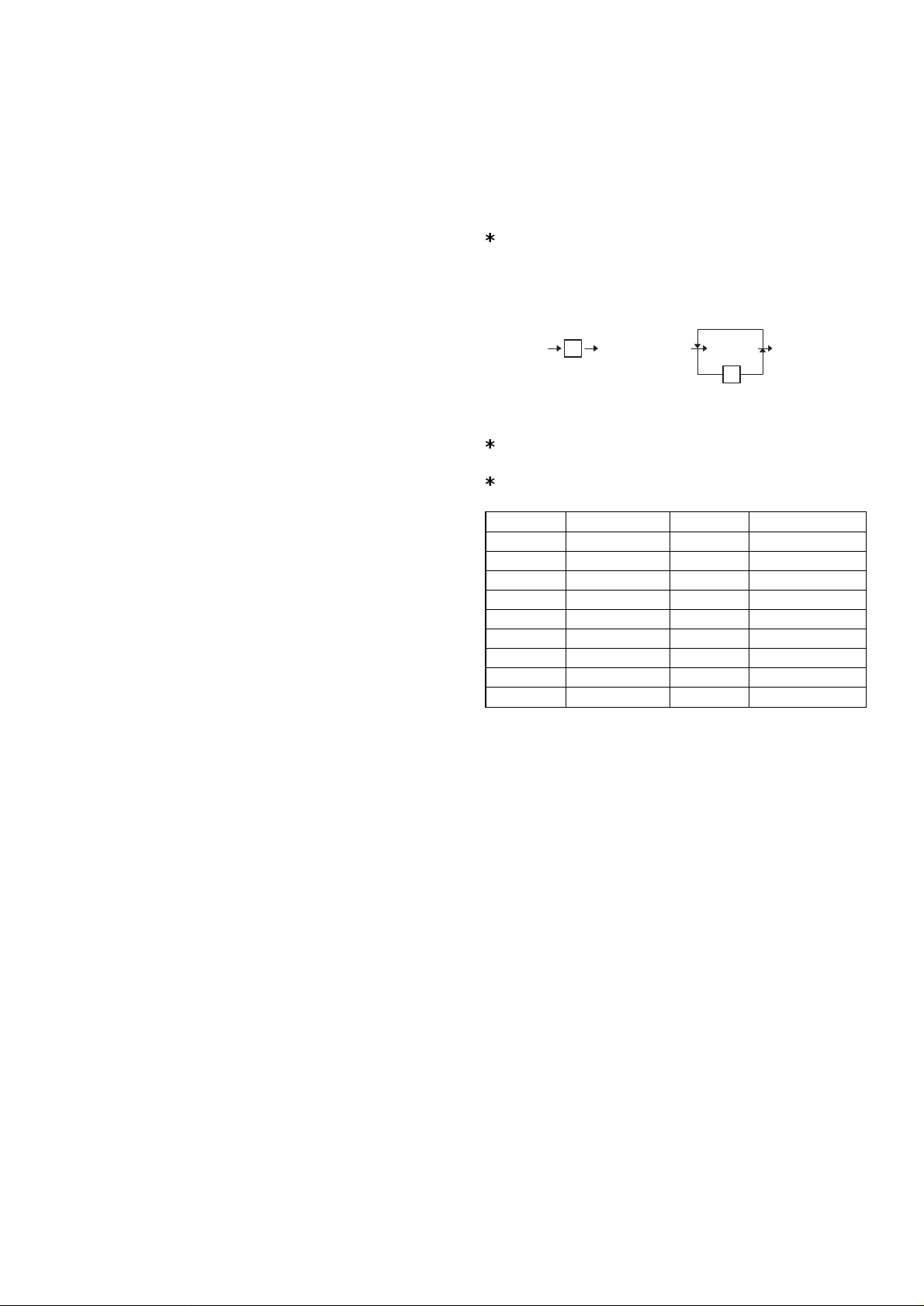
[key setup procedure]
0
Disable
*2
*1
complete.
MRS-2
executed
NOTES:
1: When the 0 key is pressed, the key of the key number on
display is disabled.
2: Push the key on the position to be assigned. With this, the key
of the key number on display is assigned to that key position.
Key number Key name Key number Key name
1 Numeric key "0" 10 Numeric key "9"
2 Numeric key "1" 11 Numeric key "00"
3 Numeric key "2" 12 Numeric key "000"
4 Numeric key "3" 13 Decimal point key
5 Numeric key "4" 14 CL key
6 Numeric key "5" 15 @/FOR key
7 Numeric key "6" 16 SB TL key
8 Numeric key "7" 17 CA/AT key
9 Numeric key "8"
0 Key position set Free key Free key setup
2. Master reset (Al l me mory clear)
There are two possible methods to perform a master reset.
• MRS-1
Used to clear all memory contents and return machine back to its
initial settings and return keyboard back to default keyboard layout.
Procedure
1) Unplug the AC cord from the wall outlet.
2) Set the MODE switch to the (SRV′) position.
3) Plug in the AC cord to the wall outlet.
4) While holding down JOURNAL FEED key, turn to (SRV) position
from (SRV′) position.
• MRS-2
Used to clear all memory and keyboard contents.
This reset returns all programming back to defaults. The keyboard
must be entered by hand.
This reset is used if an application needs different keyboard layout
other than that supplied by a normal MRS-1.
– 1 –
Page 3
CHAPTER 2. LIST OF OPTIONS
1. Options
No. NAME MODEL DESCRIPTION
1 EXPANSION RAM CHIP ER-03RA 512K bytes RAM CHIP
2 REMOTE DRAWER ER-04DW
3 PRESETS LOADER ER-01FD/02FD FD unit
4 KEY TOP KIT ER-11KT7 1 × 1 KYE TOP UNIT
ER-12KT7 1 × 2 KYE TOP UNIT
ER-22KT7 2 × 2 KYE TOP UNIT
ER-11DK7G 1 × 1 DUMMY KYE KIT
ER-51DK7G 5 × 1 DUMMY KYE KIT
5 COIN CASE ER-55CC2 for "U" version
6 COIN CASE ER-48CC2 for "A" version
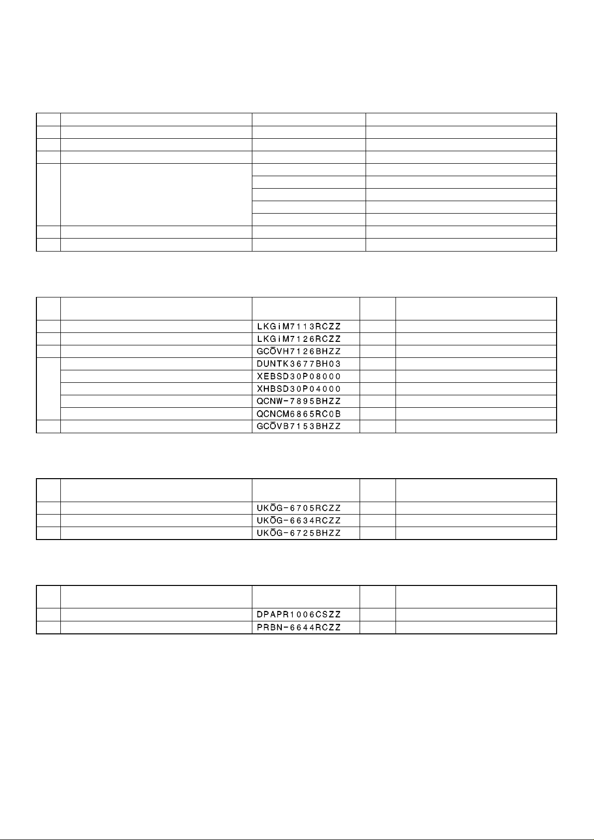
2. Service options
No. NAME PARTS CODE
1 SERVICE KEY
2 MODE KEY GRIP COVER
3 DRIP-PROOF KEYBOARD COVER
4 JOURNAL NEAR END SENSOR UNIT
Screw (Sensor unit – Top cabinet)
Screw (Sensor unit – Earth wire – Top cabinet)
Earth wire
Connector (2pin)
5 TEXT PRESET KEYBOARD COVER
3. Service tools
No. NAME PARTS CODE
1 RS-232 LOOP BACK CONNECTOR
2 KEY TOP REMOVER
32 × 2 KEY TOP INSTALLING JIG
4. Supplies
No. NAME PARTS CODE
1 ROLL PAPER
2 INK LIBBON
PRICE
RANK
AF
AL OP key only
BE Include the switch cover
BB Q’ty: 1
AA Q’ty: 1
AA Q’ty: 1
AF Q’ty: 1
AA Q’ty: 1
BH
PRICE
RANK
BU
AX
BB
PRICE
RANK
AR 5 roll /pack
AZ
DESCRIPTION
DESCRIPTION
DESCRIPTION
– 2 –
Page 4

CHAPTER 3. REMOVING THE TOP
CHAPTER 4. REMOVING THE
CABINET
1) Remove the printer cover .
2) Remove the 4 screws
1
2
.
2
Printer
PRINTER UNIT
1) Remove the top cabinet.
2) Remove the two screws
3) Remove the printer cable
4) Remove the printer unit
3
2
1
.
.
from the top cabinet.
2
3) Separate the top cabinet and the bottom cabinet.
Note: Transformer cable
tom cabinet are connected to the main PWB on the top
cabinet. Be careful when separating them from the bottom
cabinet.
4) Remove transformer cable
PWB.
5
and the drawer cable on the bot-
and drawer cable from the main
6
– 3 –
Page 5

CHAPTER 5. REMOVING THE MAIN
PWB
1) Remove the top cabinet.
2) Remove the printer unit.
3) Remove the following connector cables from the main PWB.
Dry battery cable
Pop up display cable
Note: The pop-up cable is fixed with the holder not to make
contact with the heat radiating plate on the main PWB. Be
careful of it when installing.
Mode switch cable
Keyboard cable
Front display cables
4) Remove the RS232 cable from the RS232 PWB .
5) Remove the screw
6) Remove the four screws
7) Remove the two screws
and grounding wire .
and main PWB .
and RS232 PWB .
2. Installation procedure
1) Remove the top cabinet.
2) Connect the remote drawer cable
the main PWB. (Location: CN7)
3) Use nippers to cut off drawer cable binding holder
bottom cabinet, and bind drawer cable
Screw
used in this case is an accessory of the ER-04DW.
to the drawer connector on
of the ER-04DW.
on the
11
12
10
6
13
3
4
8
9
5
1
2
9
7
CHAPTER 6. REMOTE DRAWER:
ER-04DW
CAUTION:
The drawer unit should be securely fitted to the supporting platform
to avoid instability when the drawer is open.
1
4) Use nippers to cot off the drawer cable split pin
cabinet, and attach the top cabinet.
3
2
1
of the top
4
1. Outline
The ER-A440 allows connection of one remote drawer ER-04DW.
– 4 –
Page 6

CHAPTER 7. EXPANSION RAM
CHAPTER 8. JOURNAL NEAR END
CHIP (ER-03RA)
1. Outline
ER-03RA: 512KB SRAM chip
2. Installation procedure
Before working on the installation, turn off the power switch on the
ECR and unplug the AC cord from the AC outlet.
Also save the memory contents bef ore proceeding to the installation
work.
1) Remove the top cabinet.
2) Install the ER-03RA to the IC socket on the Main PWB. (Location
No. IC14)
3) Master reset the ECR.
4) Load the data in memory which had been saved.
5) Program reset the ECR.
ER-03RA
SENSOR
(DUNTK3677BH03)
1. Parts list
To install the journal near end sensor, the following parts are
reguired.
NO. PARTS NAME PARTS CODE
JOURNAL NEAR
END SENSOR
UNIT
Screw (Sensor
unit-Top cabinet)
Screw (Sensor
unit-Earth wire-Top
cabinet)
Earth wire AF 1
Connector (2 pin) AA 1
2. Installation procedure
1) Remove the Printer cover.
2) Remove the Top cabinet.
3) Remove the Printer unit.
4) Remove the Main PWB unit.
5) Install the Sensor unit
6) Install the Earth wire
7) Fix the Earth wire
to the Top cabinet with the Screw .
to the Sensor unit with the Screw .
to the Top cabinet with the Screw.
PRICE
RANK
BB 1
AA 1
AA 1
Q’ty
2
1
4
Through the earth wire into the thins.
3
– 5 –
Page 7

8) Solder the Connector (2 pin) to the Main PWB unit. (Location:
CN8 NEJ)
Solder the connector(2pin).
2. Installation procedure
ER-22KT7
ER-12KT7
ER-11KT7
9) Connect the Sensor unit cable to the Connector (2 pin) to the
Main PWB unit. (Location: CN8 NEJ)
CHAPTER 9. KEY TOP KIT
1. Outline
The ER-A440 employs the following key top (option) to allow additional installation of the key top and change in the key layout.
MODEL NAME DESCRIPTION
ER-11KT7 1 × 1 Key top
ER-12KT7 1 × 2 Key top
ER-22KT7 2 × 2 Key top
ER-11DK7G 1 × 1 Dummy key
ER-51DK7G 5 × 1 Dummy key
ER-22KT7
ER-12KT7
ER-11KT7
– 6 –
Page 8

ER-12KT7, ER-22KT7
1) Attach two spacers to the keyboard frame.
Yellow
White
(When using 2 × 2 key top installing jig (UKOG-6725BHZZ) for
installation)
1) Remove the key label and the key cap from the key top.
2) Attach the key top so that the guide arm is under the jig.
Jig
Key top
Guide arm
3) With the jig inserted in the key top, slowly press down the key
top until the guide arm is brought into contact with the guide
holder A.
Jig
Key top
Guide arm
Yellow
White
White
Yellow
• Attach the yellow spacer to the left lower side, and the white
spacer to the right lower side.
2) The key top of the ER-12KT7 and the ER-22KT7 includes the
guide pin. Install the key top so that t he guide pin is engaged
with the spacer attached to the keyboard frame.
Guide arm
A
4) Remove the jig under the above condition 3), and press the
key top.
5) Check that the key top operates properly.
6) Install the key label and the key cap.
ER-11DK7G, ER-51DK7G
– 7 –
Page 9

COPYRIGHT 1998 BY SHARP CORPORATION
All rights reserved.
Printed in Japan.
No part of this public ation may be reproduce d,
stored in a retrieval system, or transmitted,
in any form or by any means ,
electronic, mechanical, photocopying, recording, or otherwise,
without prior written permission of the publisher.
SHARP CORPORATION
Information Systems Group
Quality & Reliability Control Center
Yamatokoriyama, Nara 639-1186, Japan
1998 May Printed in Japan
 Loading...