

Page 1
EN
ELECTRONIC CASH REGISTER
MODEL
ER-A411
ER-A421
Basic User Manual
Printed in Thailand
14F TINSE2637BSZZ
Thank you very much for your purchase of the SHARP Electronic Cash Register, Model ER-A411/
ER-A421.
Please read this manual carefully before operating your machine in order to gain full understanding
of functions and features.
Please keep this manual for future reference. It will help you if you encounter any operational
problems.
IMPORTANT
• Install the register in a location not subject to direct sunlight, unusual temperature changes, high humidity or
splashing water.
Installation in such locations could cause damage to the cabinet and the electronic components.
• Never install the register in saline areas (e.g.: close to the sea).
Installing the register in such locations could cause component failure with the corrosion.
• Never operate the register with wet hands.
The water could seep into the interior of the register and cause component failure.
• When cleaning the register, use a dry, soft cloth. Never use solvents, such as benzine and/or thinner.
The use of such chemicals will lead to discoloration or deterioration of the cabinet.
• The register plugs into any standard wall outlet (offi cial (nominal) voltage).
Other electrical devices on the same electrical circuit could cause the register to malfunction.
• If the register malfunctions, call your authorized SHARP dealer for service - do not try to repair the register
yourself.
• For complete electrical disconnection, disconnect the main plug.
• To prevent the register from moving when the drawer opens, the fi xing angle bracket is supplied with the
register. If you want to install the bracket, consult your authorized SHARP dealer.
• In order to operate the register properly, you must initialize it before operating for the fi rst time. To initialize the
register, consult your authorized SHARP dealer.
PRECAUTION
This register has a built-in memory protection circuit which is operated by a rechargeable battery pack. It
should be known that all batteries will, in time, dissipate their charge even if not used. Therefore to insure an
adequate initial charge in the protection circuit and to prevent any possible loss of memory upon installation,
it is recommended that each unit be allowed to be recharged for a period of 24 to 48 hours prior to use by the
customer.
In order to charge the battery pack, the machine must be plugged in. This recharging precaution can prevent
unnecessary initial service calls.
The battery pack is a consumable part, and its operating time will get shorter gradually each time it is recharged
for memory backup.
When the battery pack cannot be charged enough to perform memory backup, it means that the service life of
the battery pack has expired.
If this is the case, consult your authorized SHARP dealer.
For a free download of the FULL DETAILED INSTRUCTION MANUAL, please go to the following
related URL. For the countries other than described below, consult your authorized SHARP dealer.
- The United Kingdom and Republic of Ireland: www.sharp-pos.co.uk
- Netherlands and Belgium and Luxemburg: www.sharp.nl
- Sweden: www.sharp.se
CAUTION:
The cash register should be securely fitted to the supporting platforms to avoid instability when the drawer is open.
CAUTION:
The socket-outlet shall be installed near the equipment and shall be easily accessible.
VORSICHT:
Die Netzsteckdose muß nahe dem Gerät angebracht und leicht zugänglich sein.
ATTENTION:
La prise de courant murale devra être installée à proximité de l’équipement et devra être facilement accessible.
AVISO:
El tomacorriente debe estar instalado cerca del equipo y debe quedar bien accesible.
VARNING:
Det matande vägguttaget skall placeras nära apparaten och vara lätt åtkomligt.
LET OP:
Het stopcontact dient in de buurt van de kassa en gemakkelijk toegangbaar te zijn.
Caution Scanner connection
In order to allow a plug & play connection of the optional scanner the Pin 9 of the D-Sub
connector 1 (Channel 1) uses +5V.
Be very careful of this +5V in case connection of a different device should be done so that a
damage of the register or device is avoided.
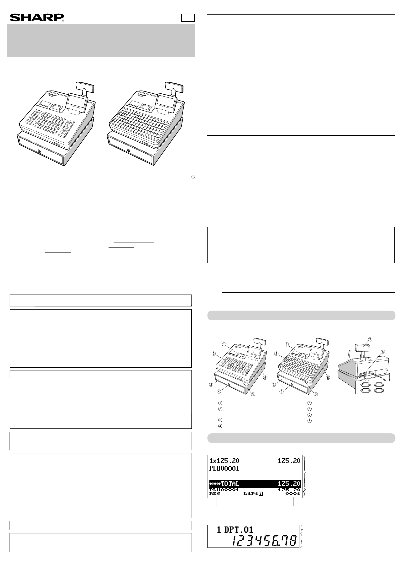
Part Names and Functions
1
External View
■Front view ■Rear view
ER-A411 ER-A421
CAUTION:
For a complete electrical disconnection pull out the mains plug.
VORSICHT:
Zur vollständigen elektrischen Trennung vom Netz den Netzstecker ziehen.
ATTENTION:
Pour obtenir une mise hors-circuit totale, débrancher la prise de courant secteur.
AVISO:
Para una desconexión eléctrica completa, desenchufar el enchufe de tomacorriente.
VARNING:
För att helt koppla från strömmen, dra ut stickproppen.
LET OP:
Trek de stekker uit het stopcontact indien u de stroom geheel wilt uitschakelen.
WARNING:
This is a Class A product. In a domestic environment this product may cause radio interference in which case the user
may be required to take adequate measures.
FOR CUSTOMERS IN U.K.
IMPORTANT
The wires in this mains lead are coloured in accordance with the following code:
BLUE: Neutral
BROWN: Live
As the colours of the wires in the mains lead of this apparatus may not correspond with the coloured markings
identifying the terminals in your plug proceed as follows.
The wire which is coloured BLUE must be connected to the terminal which is marked with the letter N or coloured black.
The wire which is coloured BROWN must be connected to the terminal which is marked with the letter L or coloured red.
The apparatus must be protected by a 3A fuse in the mains plug or distribution board.
CAUTION: DO NOT CONNECT THE LIVE (BROWN) WIRE OR THE NEUTRAL (BLUE) WIRE TO THE EARTH
TERMINAL OF YOUR 3-PIN MAINS PLUG.
Shielded interface cables must be used with this equipment to maintain compliance with EMC regulations.
Printer cover
Keyboard
(ER-A411: Normal type, ER-A421: Flat type)
Drawer
Drawer lock
Displays
■Operator display
Mode name Status information Clerk/cashier code
■Customer display
Text/message display area
1
2
SD card slot
Operator display
Customer display
RS232
Sales information area:
Sales information you have just entered such as items
and prices will appear between 1st line and 3rd line.
Total is always appear at 4th line.
Numeric entry area
Status area
3
4
Noise level LpA: 57.6 dB(A-weighted)
Measured according to EN ISO 7779:2001
[Maximum value if the cash drawer springs open LpAI: 77.0 dB(A-weighted)]
Numeric display area
Page 2

Keyboard
Standard keyboard layouts for ER-A411 and ER-A421 are as shown below.
For details on the key functions and optional keys, refer to “FULL DETAILED INSTRUCTION MANUAL”.
■ER-A411
Selecting an Operating Mode
2
Mode Selection Window
When you turn the register on and press the key, the mode selection window will appear on the display.
For example, when a clerk is signed on, the following window will appear.
Operating Modes
Department keys
■ER-A421
Department keys
Direct PLU keys
Main Functional Overview
The register has the following main functions. For details, refer to “FULL DETAILED INSTRUCTION MANUAL”.
You can select any mode other than REG from the list in the mode selection window. Your register supports the
following operating modes:
This mode allows you to enter various sales information. The mode selection window
REG mode
OPXZ mode This mode allows clerks to take X or Z reports on their sales information.
OFF mode
X1/Z1 mode This mode is used to take various daily total reports (X1/Z1 reports).
X2/Z2 mode This mode is used to take various weekly or monthly reports (X2/Z2 reports).
PGM1 mode
PGM2 mode
AUTO KEY mode This mode allows you to program AUTO menu key and automatic sequencing keys.
SD CARD mode
iSDC mode
Prior to Making Entries
3
does not list this mode. To select this mode from the mode selection window, press
the C key.
This mode locks all operations of the register. When you select this mode, the
window will disappear. Pressing any key turns the register ON.
This mode allows you to program those items which need to be changed often such
as unit prices and discount percentages.
This mode allows you to program all items including date, time, functions, and the
items that can be programmed in the PGM1 mode.
This mode allows you to save and load the data of your register to and from an SD
card.
This mode allows you to save and load the data of your register to and from the
server using a WiFi SD card.
Item Entries
Single item entries
Repeat entries
Multiplication entries
Split-pricing entries
Successive multiplication entries
Single item cash sale (SICS)/single item fi nalize
(SIF) entries
Scan entries
Special Entries for PLU/EAN
Promotion function
PLU/EAN link entries
EAN learning function
PLU/EAN information inquiry (view) function
EAN price change function
Set PLU/EAN entries
PLU level shift (for direct PLUs)
Price level shift
Condiment entries
Display of Subtotals
Subtotal
Difference subtotal (Differ ST)
Finalization of Transaction
Cash entries
Check entries
Credit entries
Computation of VAT (Value Added Tax)/Tax
VAT/tax system
VAT shift entries
Guest Check (GLU)
Guest look up (GLU) system
Deposit entries
Bill separation by item, amount, person
Bill printing
Auxiliary Entries
Refund entries
Percentage discount
Amount discount
Non-add code entry
Tip entries
Payment Treatment
Currency exchange
Received-on-account entries
Paid-out entries
No-sale (exchange)
Cashing a check
Cash payment transfer
Age Verifi cation
Overlapped Clerk Entry
Combined Cashier/Clerk Entry
Correction
Correction of the last entry (direct void)
Correction of the next-to-last or earlier entries
(indirect void)
Subtotal void
Correction after fi nalizing a transaction
Special Printing Function
Copy receipt printing
Guest check receipt (bill print)
Kitchen receipt print
Manager Mode
Manager sign-on
Override entries
Other Functions
Starting cash memory
Training mode
SD card mode
Electronic journal
Electronic journal data view function
WiFi SD card mode
Reports
General report
Transaction report
Department report
PLU/EAN report
Hourly report
Clerk report (All/Individual)
Daily net report
Electric Journal (Filter function)
Flash reports
Euro change
Compulsory cash/check declaration
Preparations for Entries
■Receipt and journal paper rolls
If the receipt or journal paper roll is not set in the register or it is getting low, install a new one according to
section “Replacing the Paper Rolls” under “Operator Maintenance.”
■Receipt ON/OFF function
You can disable receipt printing in the REG mode to save paper using the receipt function. Press the key.
Select “1 RCP SW.” and press the
When the function is in the OFF status, the receipt off indicator “R” is highlighted.
Your register will print reports regardless of the receipt state. This means that the receipt roll must be
D
installed even when the receipt state is “OFF”.
key. Select “2. OFF” to disable receipt printing and press the key.
■Clerk assignment
Prior to any item entries, a clerk must enter his/her clerk code into the register.
To sign on:
Clerk code Secret code
To sign off:
(In case secret code is 0000)
or
Error Warning
In the following examples, your register will go into an error state accompanied with a warning beep and the
error message on the display. Clear the error state by pressing the
remedy the problem.
- When you exceed a 32-digit number (entry limit overfl ow):
Cancel the entry and re-enter a correct number.
- When you make an error in key operation:
Clear the error and try the entry again.
- When you make an entry beyond a programmable amount entry limit:
Check to see if the entered amount is correct. If it is correct, it can be rung up in the MGR mode. Contact
your manager.
- When an including-tax subtotal exceeds eight digits:
Clear the error message by pressing the
key and then press a media key to fi nalize the transaction.
key and then take the proper action to
(Continued on back side)
Page 3

Entries
4
Reading and Resetting Sales
5
Basic Sales Entry
Listed below is a basic sales entry example when selling items by cash. For details, refer to “FULL DETAILED
INSTRUCTUION MANUAL”.
Enter the clerk code and press the key.
1.
Enter the unit price and press the appropriate department
2.
key.
Repeat step 2 for all department items.
3.
When the item entry is completed, press the key.
4.
The total amount due is displayed.
Receive the amount from your customer, and enter the
5.
amount by the numeric keys.
Press the key. The change due is displayed, and the
6.
drawer is opened.
Close the drawer.
7.
Clerk assignment
Item entries
Displaying subtotal
Amount tendered
Finalizing the transaction
*
: indicate department keys.
Key operation example
1500
2300
1
*
*
4000
Department Entries
Enter a unit price and press a department key.
If you use a programmed unit price, press a department key
only.
When using a programmed unit price
Department keyUnit price
(max. 8 digits)
PLU (Price Look Up) Entries
■PLU code entry (max. 5 digits)
Enter a PLU code using the numeric keys, and press the key.
For example, enter “71” and press the key for “PLU 00071”.
For ER-A421, press the key instead of the key.
PLU code or
■Direct PLU entry (ER-A421 only)
Enter a unit price and press a direct PLU key.
If you use a programmed unit price, press a direct PLU key
only.
When using a programmed unit price
Direct PLU keyUnit price
(max. 8 digits)
EAN Entries
■Create EAN8/13-Codes in REG mode
This is the easiest way to register and to store EAN Codes before you open your shop or to work for the fi rst
time with the cash register.
After an EAN code scanning, you may be requested to enter a unit price with the display “UNDEFINED CODE”
and beep sound. Set the unit price, department code, and delete type.
“UNDEFINED CODE” display
and beep sounds
Scan an undefined
EAN code
Unit price Dept. code
* Select “2 NO DELETE” to store the article continuously.
At the next scan entry of this EAN code, the registration is automatically done without the above steps.
Dept. code input window
is displayed.
Delete method selection
window is displayed.
*Selection of
delete method
Overview
• Use the reading function (X) when you need to take the reading of sales information entered after the last
resetting. You can take this reading any number of times. It does not affect the register’s memory.
• Use the resetting function (Z) when you need to clear the register ’s memory. Resetting prints all sales
information and clears the entire memory except for the GT1 through GT3, reset count, and consecutive
number.
• X1 and Z1 reports show daily sales information. You can take these reports in the X1/Z1 mode.
• X2 and Z2 reports show periodic (monthly) consolidation information. You can take these reports in the X2/Z2
mode.
• In the OP X/Z mode, a clerk can take his or her report.
• This register supports various types of reports including general report, department report, PLU/EAN report,
and clerk report. For details on available reports, refer to “FULL DETAILED INSTRUCTION MANUAL”.
• If you want to stop the printing report, press the
• When both sales quantities and sales amounts are zero, printing is skipped. If you do not want to skip,
D
change the programming. For details, refer to “FULL DETAILED INSTRUCTION MANUAL”.
• “X” represents read symbol and “Z” represents reset symbol in the reports.
• When printing is performed continuously, the printing may be intermitted for several seconds. After the
intermission, the printing will be restarted.
C
key.
How to Take a Report
Press the key.
1.
Select the appropriate mode from the following by using the key, and press the key.
2.
1 OPXZ MODE
3 X1/Z1 MODE
4 X2/Z2 MODE
Select the operation from the following by using the key, and press the key to display the items list.
3.
1 READING
2 RESETTING
Select the appropriate report title.
4.
Press the key.
5.
Flash Report
You can take fl ash reports (display only) in the X1 mode for department sales, cash in drawer (CID) and sales
total at the point you take the report.
Press the key.
1.
Select the “3 X1/Z1 MODE” by using the key, and press the key.
2.
Select “3 FLASH MODE”, and press the key.
3.
Select the appropriate report title from the following by using the key.
4.
1 DEPT. SALES Department sales
2 CID Cash in drawer
3 SALES TOTAL Sales total
Press the key.
5.
When you select “1 DEPT. SALES” in step 4, select the appropriate department from the departments list.
D
Operator Maintenance
6
In Case of Power Failure
■EAN code entry (8 or 13 digits)
Enter the EAN code using the numeric keys, and press the key.
For ER-A421, press the
key instead of the key.
■EAN code scanning (8 or 13 digits)
Read the EAN code on the item with the scanner.
Scan EAN code
EAN code
or
Correction
■Correction of entered number ( )
When you enter an incorrect number, delete it by pressing the key immediately after the entry.
■Correction of the last entry ( )
If you make a mistake when making a department entry, PLU entry, percentage ( ) and discount ( ), you
can correct this entry by pressing the
■Correction of earlier entries ( ➔ )
You can correct any incorrect entry made during a transaction if you fi nd it before fi nalizing the transaction by
pressing the
key. Move the cursor to the item to be voided and press the key.
■Subtotal void ( ➔ ➔ )
You can void an entire transaction. Once subtotal void is executed, the transaction is aborted and the register
issues a receipt.
Press the key immediately after pressing the key. And then press the key again.
■Correction after fi nalizing a transaction (VOID mode)
When you need to void incorrect entries that are found after fi nalizing a transaction or cannot be corrected by
direct, indirect or subtotal void, the following steps should be taken.
Enter to the manager mode by following the steps on the
1.
right.
The key is not included in the standard keyboard for ER-A421.
D
To use the VOID mode, consult your authorized SHARP dealer.
Press the
2.
Repeat the entries that are recorded on an incorrect
3.
receipt.
key to put your register in the VOID mode.
key immediately.
Manager
code
Secret
code
or
When power is lost, the register retains its memory contents and all information on sales entries.
• When power failure is encountered in register idle state or during an entry, the register returns to the normal
state of operation after power recovery.
• When power failure is encountered during a printing cycle, the register carries out the correct printing
procedure after power recovery.
In Case of Printer Error
If the printer runs out of paper, the printer will stall, and “PAPER EMPTY” will appear on the display. Key entries
will not be accepted. Referring to “Replacing the Paper Rolls” in this chapter, install a new paper roll in the
proper position, then press the key. The printer will print the power failure symbol and resume printing.
If the print roller arm comes up, the printer stalls, and “HEAD UP” will appear on the display. Key entries will
not be accepted. Push down the arm until it is securely locked, then press the
power failure symbol and resume printing.
key. The printer will print the
Cautions in Handling the Printer and Recording Paper
■Cautions in handling the printer
• Avoid the following environments:
Dusty and humid places
Direct sunlight
Iron powder (A permanent magnet and electromagnet are used in this machine.)
• Never pull the paper when the print roller arm is locked. First lift up the arm, and then remove the paper.
• Never touch the surface of the print head and print roller.
■Cautions in handling the recording paper (thermal paper)
• Use only the paper specifi ed by SHARP.
• Do not unpack the thermal paper until you are ready to use it.
• Avoid heat. The paper will color at around 70°C.
• Avoid dusty and humid places for storage. Avoid direct sunlight.
• The printed text on the paper can discolor under the following conditions:
Exposure to high humidity and temperature
Exposure to the direct sunlight
Contact with glue, thinner or a freshly copied blueprint.
Heat caused by friction from scratching or other such means.
Contact with a rubber eraser or adhesive tape.
• Be very careful when handling the thermal paper. If you want to keep a permanent record, copy the printed
text with a photocopier.
Page 4

Replacing the Paper Rolls
The register can print receipts and journals. For the printer, you must install the paper rolls (receipt and journal
paper rolls) provided with the register.
• Be sure to set a paper roll prior to using your machine, otherwise it may cause a malfunction.
• Be careful then to set the roll correctly.
(How to set the paper roll)
To the printer
Correct
■Recording paper specifi cations
Be sure to use paper rolls specifi ed by SHARP.
The use of any other paper rolls than specifi ed could cause paper jamming, resulting in register malfunction.
Paper specifi cation
Paper width: 57.5 ± 0.5 mm
Max. outside diameter: 80 mm
Quality: High quality (0.06 to 0.08 mm thickness)
Paper tube: 18 mm
■Removing the paper rolls
When a red dye appears on the paper roll, it is time to replace the existing paper roll. Replace the paper roll
with a new one. If you plan not to use your register for an extended period of time, remove the paper roll, and
store it in the appropriate place.
Print roller arm
Print roller
release lever
To the printer
Incorrect
Remove the printer cover.
1.
<Receipt side>
Lift up the print roller release lever to unlock the print roller arm. The arm
2.
will come up slightly.
Open the print roller arm of the receipt side.
Remove the paper roll from the paper roll cradle of the receipt side.
3.
Mount the paper holding plate onto the take-up spool.
10.
Set the spool on the bearing, and press the journal paper feed key to
take up excess slack in the paper.
Replace the printer cover.
11.
Press the key to make sure the paper end comes out of the printer
12.
cover and clean paper appears.
If the paper end does not come out, open the printer cover, and pass the
paper end between the paper cutter and the paper guide of the printer
D
cover, and replace the printer cover.
■Removing a paper jam
Remove the printer cover.
1.
Lift up the print roller arm.
2.
Remove the paper jam. Check for and remove any shreds of paper that may remain in the printer.
3.
Reset the paper roll correctly by following the steps in “Installing the paper rolls”.
4.
Drawer Handling
■Locking the Drawer
Develop the habit of locking the drawer when not using the register for any
extended period of time.
■Removing the Drawer
Till
Coin case
To lock: Insert the key into the drawer lock and turn it
TL-1
To remove the drawer, pull it out and lift it up.
• To prevent burglary, it is a good idea to empty the drawer after work and
D
leave it open at the end of the day.
• Coin case is detachable.
To unlock: Insert the key into the drawer lock and turn it
90 degrees counter-clockwise.
90 degrees clockwise.
Take-up
spool
Cut
Print roller arm
■Installing the paper rolls
<Journal side>
Press the key to advance the journal paper until its printed part is out
4.
of the way.
Cut the paper and remove the take-up spool from the bearing.
5.
Lift up the print roller arm of the journal side.
6.
Remove the paper roll from the paper roll cradle of the journal side.
7.
Remove the paper holding plate of the take-up spool, and remove the
8.
printed journal roll from the spool.
<Receipt side>
Remove the printer cover and open the print roller arm of the receipt side
1.
by following the steps in “Removing the paper rolls”.
Set a paper roll in the paper roll cradle of the receipt side as per the
2.
diagram.
Drawer
■Manually Opening the Drawer
In case of a power failure or if the machine is out of order, locate the lever
at the bottom of the machine and move it in the direction of the arrow to
open the drawer. The drawer will not open if it is locked with the drawer
lock key.
Lever
Before Calling for Service
If you encounter any of the following problems, please read below before calling for service.
The display does not illuminate.
• Is power supplied to the electric outlet?
• Is the power cord plug out or loosely connected to the
electric outlet?
• Is the register in screen-save mode?
The display is illuminated, but the whole machine
refuses entries.
• Is a cashier code assigned to the register?
• Is a clerk code assigned to the register?
• Is the register in the REG mode?
No receipt is issued.
• Is the receipt paper roll properly installed?
• Is there a paper jam?
• Is the receipt function in the “OFF” status?
• Is the print roller arm securely locked?
No journal paper is taken up.
• Is the take-up spool installed on the bearing properly?
• Is there a paper jam?
Printing is unusual.
• Are the printer head/sensor/roller clean?
• Is the paper roll properly installed?
Feed the end of the paper along with the paper positioning guides as per
3.
the diagram.
While holding down the paper, slowly close the print roller arm of the
4.
receipt side, and push down the
click locking the arm.
If the print roller arm is not securely locked, printing is not done right. If this
problem occurs, open the arm, and close the arm as instructed above.
D
Wait until the excess paper is automatically cut off, and remove it.
5.
Do not remove the excess paper until the receipt cutter stops completely.
Trying to remove the paper before the cutter stops completely could cause
D
paper jamming.
mark on the arm until you hear a
<Journal side>
Lift up the print roller arm of the journal side.
6.
Set a paper roll in the paper roll cradle of the journal side as per the
7.
diagram.
While holding down the paper, slowly close the print roller arm of the
8.
journal side, and push down the arm until you hear a click locking the
arm.
Specifi cations
Model:
ER-A411/ER-A421
Dimensions:
360(W) × 425(D) × 365(H)* mm
* With the customer display popped up. When it is
completely lowered, the height is 330 mm.
Weight:
Approx.12.0kg
Power source:
Offi cial (nominal) voltage and frequency
Power consumption:
Standby: 7.1W (220 to 230V, 50Hz/60Hz)
7.3W (230 to 240V, 50Hz)
Operating: 31.6W (220 to 230V, 50Hz/60Hz)
28.1W (230 to 240V, 50Hz)
Working temperatures:
0 to 40 ºC
Display:
Operator display: LCD display with tilt mechanism
192(W) × 80(H) dots
Customer display: 2-line LCD display
Printer:
Type:
Two-station thermal printer
Printing speed:
Approx. 15 lines/second
Printing capacity:
30 digits each for receipt/journal paper
Other functions:
• Receipt ON/OFF function
• Compression print for an electronic journal/journal
• Receipt and journal independent paper feed
function
Logo:
Graphic logo printing:
Size: 130(H) x 360(W)pixel
Area of black must be less than 35% of all area.
Logo message printing:
Logo message for the receipt
(max. 30 characters x 6 lines)
Paper Roll:
Width: 57.5±0.5 mm
Max. diam.: 80 mm
Quality: High quality (0.06 to 0.08 mm thickness)
Cash drawer:
5 slots for bills and 8 for coin denominations
Accessories:
Basic User Manual: 1 copy
Paper roll: 2 rolls
Take-up spool: 1
Paper holding plate: 1
Drawer lock key: 2
Standard key sheet: 1 (for ER-A421 only)
Programming key sheet: 1 (for ER-A421 only)
Fixing angle bracket: 1
Paper positioning guides
Paper holding plate
Spool
Remove the paper holding plate from the spool.
9.
Insert the end of the paper into the slit in the spool. (Press the journal
paper feed key to feed more paper if required.)
Wind the paper two or three turns around the spool shaft.
SHARP ELECTRONICS (Europe) Ltd.
4 Furzeground Way, Stockley Park Uxbridge,
UB11 1 EZ, United Kingdom
 Loading...