

Page 1
Dealer Knowledge Book
ERA410
ERA420
ERA410
MODEL ER-A410 & ER-A420
ROM VERSION RCC2A
Contents
Category
Introduction …………………………………………………………………………………………………………………
SECTION 1. System Presets
Overview……………………………………………… ………………..…………………………………
Prior to Beginning……………………………………………..……………………………….………….
System Preset Job No……………………………………………………………………………………
SECTION 2. Free Key Layouts
Free Key Layout Set Up….………………………………………………………………………………
Free Key Layout Readings..……………………………………………………………..……………...
SECTION 3. File Allocation
Allocating Memory Files……………………………………………………….….……..……………….
SECTION 4. Peripherals
Peripheral Device Overview………………………………….……………….……….………………...
Coin Dispenser...…………………………………………………………...……………………………..
Scale………………………………………………………………………………………..………………
Printers…………………………………………………………………………………….……………….
Scanner…………………………………………………………………………………………………….
SECTION 5. PGM2 Mode Programming
Departments……………………………………………………………………………………………….
PLU/UPC…………………………………………………………………………………………………...
Cashiers……………………………………………………………………………………………………
Function & Media Keys…………………………………………………………………………………..
Machine Settings……………………………………………………………………………………….....
SECTION 6. COM Communication
Overview…………………………………………………………………………………………………...
Online………………………………………………………………………………………………………
RS232 Communications Set Up………………………………………………………………………...
SECTION 7. Electronic Funds Transfer
Overview…………………………………………………………………………………………………...
Data Tran 162LT Configuration………………………………………………………………………….
Cable Connection…………………………………………………………...……….……………………
EFT Related Programming…………………………………………………...………………………….
SECTION 8. Utilities
Overview…………………………………………………………………………………………………...
02FD.EXE Installation/Usage……………………………………………………………………………
SECTION 9. SSP’s …………………………...……………………………………………………..……………………..
Notice:
Except as permitted by such license, no part of the software or documentation may be reproduced, stored in a retrieval system, or
transmitted, in any form or by any means, electronic, mechanical, recording, or otherwise, without the prior written permission of Sharp
Electronics Corporation.
The Data Tran software and/ or documentation referred to in this manual are furnished under the license by Datacap Systems, Inc. and
may only be used or copied in accordance with the terms of such license.
Designs and specification are subject to change without notice
Pg.
iii
2
3
8
29
30
32
37
38
39
40
42
46
50
64
75
76
88
113
117
131
155
156
156
162
164
165
166
166
169
187
188
194
202
Page 2

Dealer Knowledge Book
TRADEMARKS
All trademarks and registered marks are the property of their respective holders.
DISCLAIMER
The information contained in this document is furnished without assurance of peripheral/software
compatibility between Sharp POS products and the products of the suppliers listed.
Product specifications change without notification (both Sharp’ and other supplier’s products).
Sharp POS does not undertake to update materials. It is the dealer’s responsibility to keep current
with all technical issues associated with these products.
NOTICE TO USERS
This manual is intended to assist authorized Sharp dealers, with learning and understanding how to
the install and provide support for the ER-A410 and ER-A420.Please read each section carefully as it
will provide helpful hints and recommendations that will make your time more efficient and produce
time saving results. This manual is not intended for end user customers of authorized Sharp dealers.
Designs and specification are subject to change without notice Page ii of 209
Page 3

Dealer Knowledge Book
Overview
The new ER-A410 and ER-A420 Version Up model ECRs has the following new features:
1) UPC (EAN) Codes Scanning
2) Overlapping Cashier Function (Transaction Sales Suspend Mode)
3) Remote Kitchen Printer using the following Epson models:
a. TM-T88III Thermal Printer
b. TM-U220 Black & Red Dot matrix Printer
c. TM-U230 Black & Red Dot matrix Printer
Note: The program data from the old ERA410 or ERA420 with version RACC1A are NOT
compatible with the new ER-A410 or ER-A420 version RCC2A.
PC Link version for the old ER-A410 and ER-A420 will not work with the new ER-A410 and
ER-A420 ECRs.
Designs and specification are subject to change without notice Page iii of 209
Page 4

System Presets
Section-1: System Presets
Designs and specification are subject to change without notice Page 1 of 209
Page 5
System Presets
Section-1: SRV Mode Programming
SRV-mode programmings consist of service programming jobs, which define the
ERA410/ERA420 system capabilities. The service program settings are printed on the Receipt /
Journal printer.
1. SRV-mode Program Readings:
List of SRV-mode Program Reports:
SRV-Mode Related Jobs: (X = indication of availability)
Job No. Description
900 System Presets / Memory Allocation
950 Free Key – Function keys
951 Keyboard Layout – Dept & PLU Link Key Position
990 Special Service Patch Data
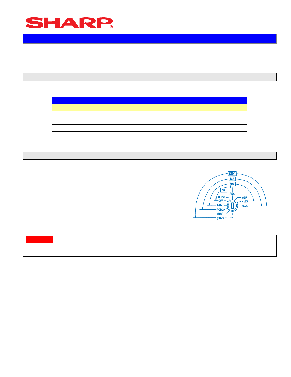
2. Entering the SRV-Mode
To enter SRV-mode programming
Procedure:
1) Place the mode switch to the SRV’ position
2) Place the AC power cord into the wall outlet
3) Place the AC power cord into the wall outlet
CAUTION:
Never enter the SRV mode in the middle of a transaction – severe damage may result to the sales
totals.
Designs and specification are subject to change without notice Page 2 of 209
Page 6
System Presets
Section-2: Prior to Beginning
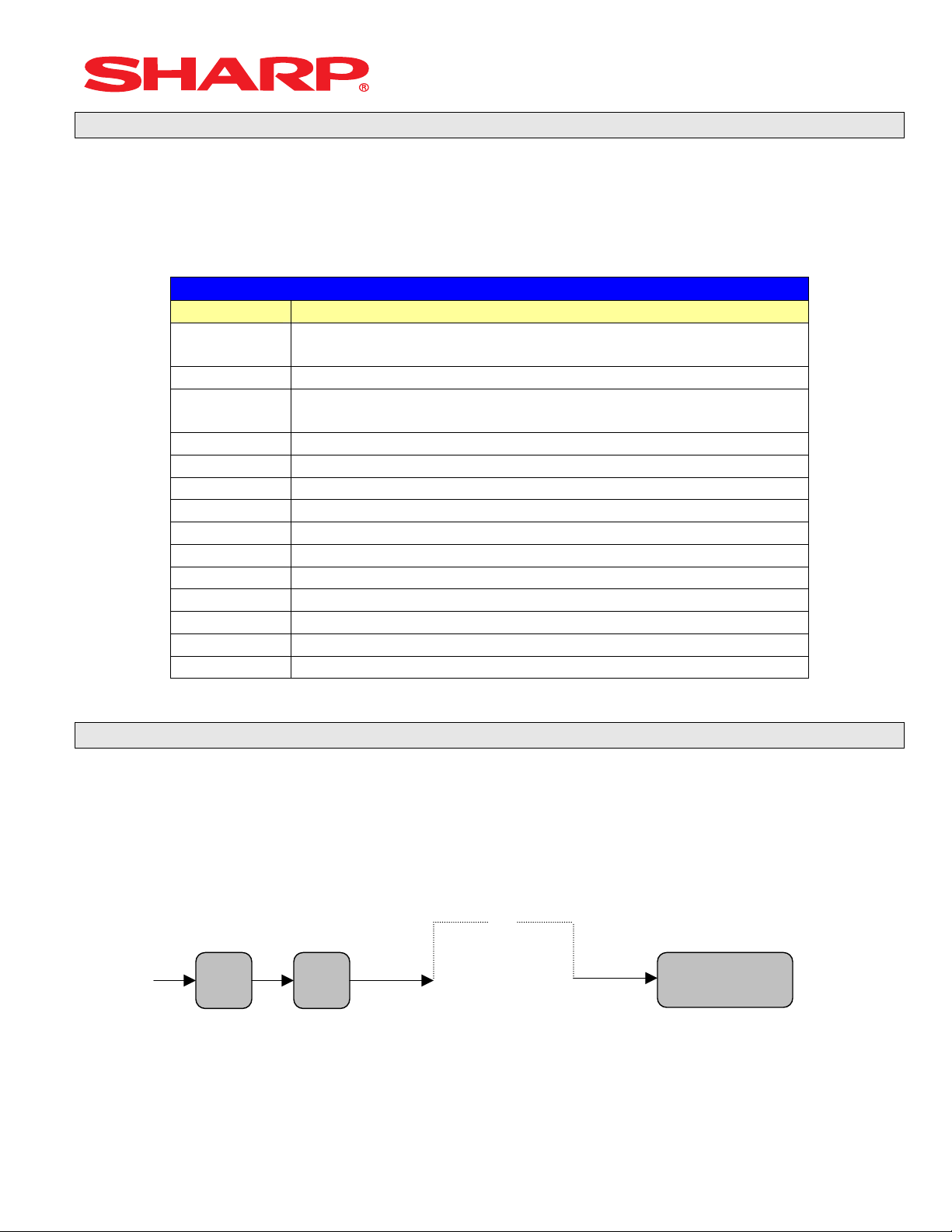
The ERA410/A420 POS terminal should be initialized by executing a master reset. The Program
and Master Reset operations are available in one of the following three types:
Type Description
Program Reset Initializes the hardware and resident program without clearing
memory and totalizers
Master Reset-1 Initializes the hardware and clears the entire memory – restoring
factory initial values
Master-Reset-2 Initializes the hardware and clears the entire memory – restoring
factory initial values and enabling free key layout of the ERA410/A420
“fixed keys”
1. Master Resets:
The Master Reset procedures are primarily performed during installation and setup of the ERA410
and ERA420 model cash registers. Each has an important role when installing the equipment.
Follow one the below procedures when you wish to perform a Master Reset.
1. General Rule:
Master Reset: Clears the entire memory and resumes initial values (default program).
Program Reset: Resumes the initial program without clearing memory.
There are 2 methods for performing a Master Reset operation.
1) Master Reset-1: Normal Master Reset (out of box setup)
Clears the entire memory and resumes initial values
2) Master Reset-2: Enables the ability to change the layout fixed keys in addition to executing
the Master Reset-1.
Fixed Keys: [0][1][2][3][4][5][6][7][8][9][0][00][000][.][@/FOR][SBTL][CA/AT]
IMPORTANT NOTES:
During the Master Reset initialization, the following actions should be noted:
1) ***MRS*** is displayed on the upper line of the operator display.
2) MASTER RESET*** is printed on the journal tape.
3) The buzzer will beep 3-times
Designs and specification are subject to change without notice Page 3 of 209
Page 7
System Presets
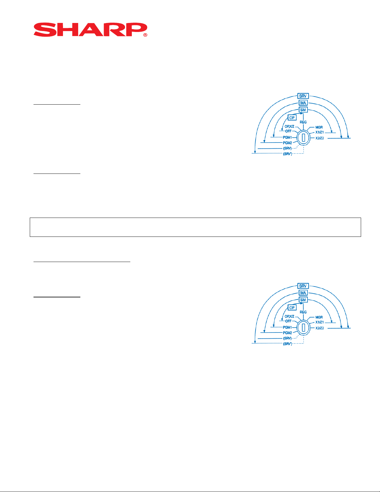
2. Master Reset-1 Operations:
There are 2 possible procedures to use in performing a Master Reset-1 operation.
Follow the below procedure when you wish to perform a program-reset (initialization)
Procedure A:
1) Place the mode switch to the SRV’ position
2) Place the AC power cord into the wall outlet
3) Depress and hold the [JOURNAL] feed key
4) Turn the mode switch from SRV’ -- > SRV position
Procedure B:
1) Remove the AC power cord from the outlet
2) Place the mode switch to the SRV position
3) Depress and hold the [JOURNAL] feed key
4) Replace the AC power cord into the wall outlet
Note:
***Procedure A must be used to reset the hardware. Procedure B cannot reset the hardware.
Master Reset-2 Operations:
There are 2 possible procedures to use in performing a Master Reset-2 operation.
Procedure A:
1) Place the mode switch to the SRV’ position
2) Place the AC power cord into the wall outlet
3) Depress and hold the [JOURNAL] & [RECEIPT] feed keys
4) Turn the mode switch from SRV’ -- > SRV position
***The operator display will show the fixed function keys (starting with the [0] key)
5) Program the Function Keys by depressing the desired location(s).
6) Once the [CA/AT] key is placed on the keyboard, ***MRS*** will be displayed and the reset
process will continued as outlined in Master Reset-1
Designs and specification are subject to change without notice Page 4 of 209
Page 8
System Presets
Procedure B:
1) Remove the AC power cord from the outlet
2) Place the mode switch to the SRV position
3) Depress and hold the [JOURNAL] & [RECEIPT] feed keys
4) Replace the AC power cord into the wall outlet
***The operator display will show the fixed function keys (starting with the [0] key)
5) Program the Function Keys by depressing the desired location(s).
6) Once the [CA/AT] key is placed on the keyboard, ***MRS*** will be displayed and the reset
process will continued as outlined in Master Reset-1
Note:
***Procedure A must be used to reset the hardware. Procedure B cannot reset the hardware.
2. Program Reset:
The Program Reset (sometimes referred to as a “Service Reset”) may be achieved with or without
a [SRV] key (part no. LKGiM7113RCZZ) based on the System Preset settings.
1. General Rule:
A Program Reset should be performed under the following general conditions:
1) After the memory allocation setting has been modified
2) When a device assignment has been modified in COM port assignment
IMPORTANT NOTE:
During the Program Reset operation, PROGRAM RESET*** is printed on the journal tape
Follow the below procedure when you wish to perform a program-reset (initialization)
2. Procedures:
Base on the SRV Job#928-B setting, there may be 3 possible procedures in performing a
Program Reset.
Procedure- A:
1) Place the mode switch to the SRV’ position
2) Place the AC power cord into the wall outlet
3) Turn the mode switch from SRV’ -- > SRV position
Designs and specification are subject to change without notice Page 5 of 209
Page 9

System Presets
Procedure- B:
1) Remove the AC power cord from the outlet
2) Place the mode switch to the SRV’ position
3) Replace the AC power cord into the wall outlet
4) Turn the mode switch clockwise to the SRV position (7 o’clock)
Procedure- C: (based on SRV Job#928-B)
1) Remove the AC power cord from the outlet
2) Place the mode key in the PGM2 position
3) Depress and hold the [RECEIPT] & [JOURNAL] feed keys
4) Replace the AC power cord into the wall outlet while holding the keys
Note:
***Procedure A must be used to reset the hardware. Procedures B and C cannot reset the
hardware.
CAUTION:
Never enter the SRV mode in the middle of a transaction – severe damage may result to the sales
totals.
Designs and specification are subject to change without notice Page 6 of 209
Page 10
System Presets
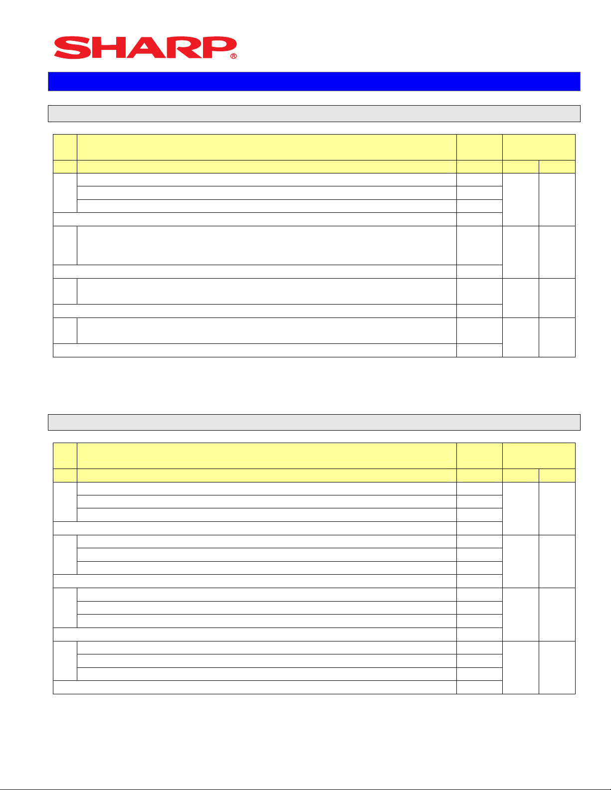
3. Recommended Set Up Procedures
To minimize unnecessary steps when installing the ERA410 and ERA420 model cash register,
please perform Job#975 (Memory Allocation), Job#900s (Service Parameters),
Job#950 (Free Key), Job#951 (Keyboard Link Position) followed by “All” PGM2 settings.
The below chart represents the SRV Job# Reference Descriptions:
SRV-Mode Related Jobs: (X = indication of availability)
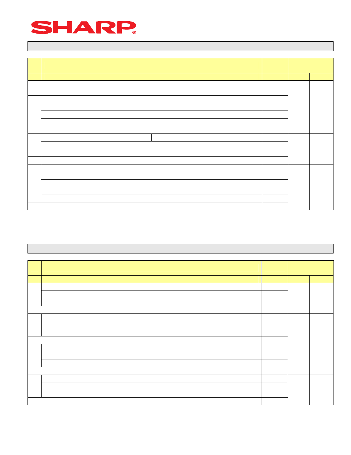
Job No. Description
901 – 929
980
930 - 939 Report Counters Z-Counters
942 – 943
969
944 PGM2 Mode Secret Code
948 Training Cashier Assignment
949 Training Mode Title Programming
950 Keyboard Layout – Function keys
951 Keyboard – Dept & PLU Keys
975 Memory File Allocation Programming
985 Euro Symbol Programming for the TM-295 Slip Printer
986 Domestic Currency Symbol Programming
987 Language Selection for Text Print
990 Special Service Patch
996, 998 Program Data Send/Receive Function
4. Service Mode Programming
System Parameters
GT Totalizers
Service mode programming is usually performed during the installation process. To change the
System Preset settings, the key operation is required:
0
XXX
[Job#]
ABCD
Designs and specification are subject to change without notice Page 7 of 209
.
@
CA/AT
Page 11
System Presets
Section-3: System Preset Job No.
System Preset: 901
Bit Description Data
A410 A420
4/0
A
2/0
1/0
Enter SUM of Selection ----^
Tax System:
B
Auto Tax 1-4 & Manual Tax System / Canadian Tax (Type 1-10) / Canadian
Tax (Type-11: VAT-on-VAT)
Enter SUM of Selection ----^
Tax Rounding System:
C
- Singapore / Normal
Enter SUM of Selection ----^
Tab Setting:
D
- Decimal setting for display and print
Enter SUM of Selection ----^
0/6/7
8/0
3/2/1/0
MRS
Defaults
0 0
0 0
0 0
2 2
NOTE:
• 901-C: The Singapore Tax Rounding method will round the tax to the nearest nickel.
System Preset: 902
Bit Description Data
A410 A420
---- ---
A
---- ---
---
Enter SUM of Selection ----^
---- ---
B
---- ---
---- ---
Enter SUM of Selection ----^
---- ---
C
---
---- ---
Enter SUM of Selection ----^
---- ---
D
---- ---
---- ---
Enter SUM of Selection ----^
MRS
Defaults
0 0
0 0
0 0
0 0
NOTE:
Designs and specification are subject to change without notice Page 8 of 209
Page 12
System Preset: 903
System Presets
Bit Description Data
A410 A420
ECR Data Copy (SIO) All RAM data Send/Receive Baud Rate (bps):
A
19200/9600
Enter SUM of Selection ----^
---- ---
B
Measure of Weight for Scale Entries Kg/Lb 2/0
---- ---
Enter SUM of Selection ----^
---
C
Tare Weight Entry is allowed Yes/No 2/0
Scale Weight System 1 Int. & 3 Dec./2 Int. & 2 Dec. 1/0
Enter SUM of Selection ----^
---- --Food Stamp System:
D
Food Stamp Forgiveness / Tax Payable in Food Stamps
Tax in Not Payable in Food Stamps / No Food Stamps
---- ---
Enter SUM of Selection ----^
5/4
3/2/1/0
MRS
Defaults
5 5
0 0
0 0
0 0
NOTE:
• 903-A is applicable for the 02FD.exe utility (not online communications)
• Manual Scale Entry is NOT allowed.
• To enabled Scale entries 906-D must be set = 1
System Preset: 904
Bit Description Data
A410 A420
Date is printed No/Yes 4/0
A
---- ---
---- ---
Enter SUM of Selection ----^
Consecutive No. is printed No/Yes 4/0
B
---- ---
---- ---
Enter SUM of Selection ----^
---- ---
C
---- ---
---- ---
Enter SUM of Selection ----^
---- ---
D
---- ---
---- ---
Enter SUM of Selection ----^
MRS
Defaults
0 0
0 0
0 0
0 0
NOTE:
904-A&B applies to Receipts, Slip, and Kitchen Print chits
Designs and specification are subject to change without notice Page 9 of 209
Page 13
System Preset: 905
System Presets
Bit Description Data
A410 A420
Tax4 Subtotal is printed on Trans. Reports No/Yes 4/0
Gross Tax4 & Refund Tax4 Totals are printed on Trans.
A
Reports
Net Tax4 Total is printed on Trans. Reports No/Yes 1/0
Enter SUM of Selection ----^
Tax is printed when the Taxable Subtotal = $0.00 Yes/No 4/0
B
Tax is printed when GST is VAT No/Yes 2/0
Tax is printed when Tax = $0.00 No/Yes 1/0
Enter SUM of Selection ----^
GST Exempt is printed on Trans. Reports No/Yes 4/0
C
Enter SUM of Selection ----^
Canadian Tax System:
D
Type10/Type9/Type8/Type7/Type6/Type5/Type4/Type3/Type2/Type1
Enter SUM of Selection ----^
No/Yes 2/0
---- ---
---- ---9/8/7/
6/5/4/
3/2/1/
0
MRS
Defaults
0 0
0 0
0 0
5 5
NOTE:
• 905-C is related to 905-D the Canadian Tax System
System Preset: 906
Bit Description Data
A410 A420
Dept. & PLU/UPC Codes are printed Yes/No 4/0
A
PLU/UPC (EAN) Stock System:
Entry is Inhibited/Error Message and Operation continues/Allowed
Enter SUM of Selection ----^
Bottle Return Function is Enabled Yes/No 4/0
B
Hash Dept. is Enabled Yes/No 2/0
---- ---
Enter SUM of Selection ----^
Multiplication System:
C
PLU/UPC (EAN) Price Look Up at Refund Entry No/Yes 4/0
D
Presetting of the Consecutive No. is Enabled No/Yes 2/0
Fractional Qty System is enabled (3 decimal places) Yes/No 1/0
Fast Food (FF sequence)/Split-Price/Successive
Multiplication/Multiplication
Enter SUM of Selection ----^
Enter SUM of Selection ----^
2/1/0
3/2/1/
0
MRS
Defaults
0 0
0 0
2 2
0 0
NOTE:
• 906-D must not be changed until after totalizers are reset (Qty 0 Æ 0.000 & vice-versus)
• Fractional entries are disabled when a SCALE is enabled in PGM2 Job #2690 programming.
Designs and specification are subject to change without notice Page 10 of 209
Page 14
System Preset: 907
System Presets
Bit Description Data
A410 A420
---- ---
A
---- ---
---- ---
Enter SUM of Selection ----^
---- ---
B
UPC (EAN) Code Printing on Journal No/Yes 2/0
UPC (EAN) Code Printing on Receipt No/Yes 1/0
Enter SUM of Selection ----^
X Report is Enforced prior to Ind./All Cashier CCD Yes/No 4/0
C
---- 2/0
Minus Dept. and PLU/UPC (EAN) items are Enabled Yes/No 1/0
Enter SUM of Selection ----^
---- ---
D
---- ---
---- ---
Enter SUM of Selection ----^
MRS
Defaults
0 0
0 0
1 1
0 0
NOTE:
• To enable Coupon PLU items 907-D must be set = 1
System Preset: 908
Bit Description Data
A410 A420
GT1 is printed on the Trans.-Z Report No/Yes 4/0
A
GT2 is printed on the Trans.-Z Report No/Yes 2/0
GT3 is printed on the Trans.-Z Report No/Yes 1/0
Enter SUM of Selection ----^
GT1 is printed on the Trans.-X Report Yes/No 4/0
B
GT2 is printed on the Trans.-X Report Yes/No 2/0
GT3 is printed on the Trans.-X Report Yes/No 1/0
Enter SUM of Selection ----^
VOID-mode operations affect the Hourly Report Yes/No 4/0
C
X//Z1 Reports may taken in X2/Z2 Mode No/Yes 2/0
Consecutive No. is Reset upon a Trans.-Z Report Yes/No 1/0
Enter SUM of Selection ----^
X/Z Report Printing: Journal only/Receipt & Journal 4/0
D
---- --Trans.-Z1 Report resets the GT Yes/No 1/0
Enter SUM of Selection ----^
MRS
Defaults
0 0
0 0
0 0
0 0
NOTE:
• 908-D: The X/Z Report printing option does not apply to Individual Cashier Report
Designs and specification are subject to change without notice Page 11 of 209
Page 15
System Preset: 909
System Presets
Bit Description Data
A410 A420
---- ---
A
Training GT is printed on the Trans.-X Report Yes/No 2/0
Training GT is printed on the Trans.-Z Report No/Yes 1/0
Enter SUM of Selection ----^
PLU/UPC (EAN) Item Data is printed on the Z Report No/Yes 4/0
B
---- ---
---- ---
Enter SUM of Selection ----^
VOID-mode & MGR VOID is printed on the Trans.-Z2 Report No/Yes 4/0
C
VOID-mode & MGR VOID is printed on the Trans.-Z1 Report No/Yes 2/0
---- ---
Enter SUM of Selection ----^
---- ---
D
---- ---
---- ---
Enter SUM of Selection ----^
MRS
Defaults
2 2
0 0
0 0
0 0
NOTE:
• 909-B: No Sales Data is printed for the PLU/UPC (EAN)-Z Report when = 4
System Preset: 910
Bit Description Data
A410 A420
---- ---
A
Overlapped Cashier Function Yes/No 1/0
---- ---
Enter SUM of Selection ----^
Cashier Code Display Appear/Hidden 2/0
Auto Sign Off at the End of the
B
Transaction
---- ---
---- ---
C
Server/Cashier Sign-on System Auto Sign-Off/Stay-Down 2/0
---- --(Fixed): Server/Cashier system is code entry 4
D
---- ---
---- ---
Yes (Everytime) / No
After Cashier Z1 Only
Enter SUM of Selection ----^
Enter SUM of Selection ----^
Enter SUM of Selection ----^
1/0
MRS
Defaults
0 0
2 2
0 0
4 4
NOTE:
• 910-A: The Cash drawer opening is based on the Individual Server preset
• 910-C: The Server stay-down system requires a manual sign-off sequence
Designs and specification are subject to change without notice Page 12 of 209
Page 16
System Preset: 911
System Presets
Bit Description Data
A410 A420
---- ---
A
---- --Fractional Qty System: Ignored/Round-Up/Round-Off 2/1/0
Enter SUM of Selection ----^
C/D Check of UPC (EAN) Yes/No 4/0
B
---- ---
---- ---
Enter SUM of Selection ----^
---- ---
C
---- ---
---- ---
Enter SUM of Selection ----^
---- ---
D
---- ---
---- ---
Enter SUM of Selection ----^
MRS
Defaults
0 0
0 0
0 0
0 0
NOTE:
• 911-A: Is ignored for Scale operations
Designs and specification are subject to change without notice Page 13 of 209
Page 17
System Preset: 912
System Presets
Bit Description Data
A410 A420
---- ---
A
---- --Date Print Format YYMMDD/DDMMYY/MMDDYY 2/1/0
Enter SUM of Selection ----^
---- ---
B
---- --Time Clock System 24-Hour System/12-Hour System 1/0
Enter SUM of Selection ----^
Receipt After-Transaction Format Detailed/Totals only 4/0
C
Copy Receipt Function is Enabled Yes/No 2/0
Receipt Footer Print Control By Media Preset/All Receipts 1/0
Enter SUM of Selection ----^
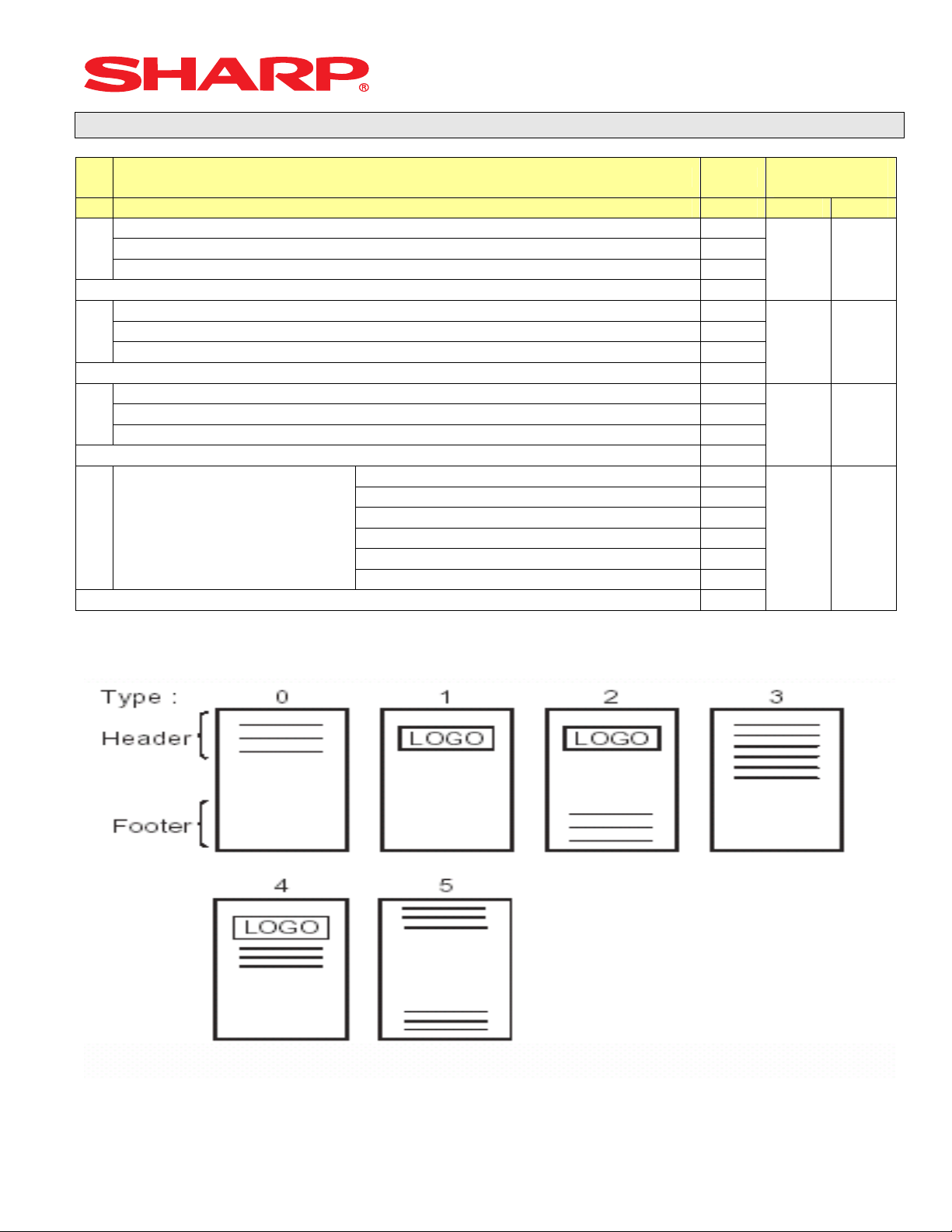
3-Line Header – No Logo Graphic Stamp 0
Graphic Logo Stamp only 1
D Logo Message Control:
Graphic Logo Stamp & 3-Line Footer 2
6-Line Header – No Stamp 3
Graphic Logo and 3-Line Header 4
3-Line Header – No Stamp/3-Line Footer 5
Enter SUM of Selection ----^
MRS
Defaults
0 0
0 0
6 6
1 0
NOTE:
• 912-D: The Graphic Logo STAMP – Must use PC Link to upload Graphical Logos to the ECRs.
• 912-D: The Graphic Logo bitmap should be 288 dots (w) x 130 dots (h) and black & white only.
Designs and specification are subject to change without notice Page 14 of 209
Page 18

System Preset: 913
System Presets
Bit Description Data
A410 A420
---- ---
A
---- --VP Total Amounts Contains: Tendered Amount/Total Amount 1/0
Enter SUM of Selection ----^
Subtotal is printed when the [SBTL] key is depressed Yes/No 4/0
B
MDSE Subtotal is printed when the [MDSE] key is depressed Yes/No 2/0
Escaping Compulsory VP and SLIP print is Enabled Yes/No 1/0
Enter SUM of Selection ----^
---- ---
C
Error-Tone System
Keyboard Buffering is Enabled No/Yes 1/0
Compulsory Drawer Closed prior to operation is enabled Yes/No 4/0
D
Error System “Misoperation”/One-Shot Error Only 2/0
Key Touch-Tone is enabled No/Yes 1/0
Until [CL] is depressed/2
seconds
Enter SUM of Selection ----^
Enter SUM of Selection ----^
2/0
MRS
Defaults
0 0
1 1
0 0
4 4
NOTE:
• 913-B: The sequence for escaping “Compulsory” VP or SLIP print operations:
Æ [.] Æ [SLIP or PRINT]
System Preset: 914
Bit Description Data
A410 A420
Receipts are printed upon [NO SALE] operations No/Yes 4/0
A
The [NO SALE] function is combined with the [CASH] key Yes/No 2/0
Tax Delete function is Enabled Yes/No 1/0
Enter SUM of Selection ----^
---- ---
B
---- --The [NO SALE] function is allowed after a Non-Add No. entry Yes/No 1/0
Enter SUM of Selection ----^
---- ---
C
VOID-mode is Enabled No/Yes 2/0
Non-Add # Entry is Compulsory at the beginning of each Trans. Yes/No 1/0
Enter SUM of Selection ----^
Manual Tax entry is Enabled No/Yes 4/0
D
Check-Cashing function is Enabled Yes/No 2/0
Non-Add # Entry is Enabled No/Yes 1/0
Enter SUM of Selection ----^
MRS
Defaults
1 1
1 1
0 0
0 0
NOTE:
Designs and specification are subject to change without notice Page 15 of 209
Page 19
System Presets
System Preset: 915
Bit Description Data MRS
A410 A420
---- ---
A
---- --Fraction Treatment Disregard/Rounding Up/Rounding Off 2/1/0
Enter SUM of Selection ----^
---- ---
B
---- ---
---- ---
Enter SUM of Selection ----^
---- --SBTL (-) or SBTL (%) within the same
C
Transaction
Enter SUM of Selection ----^
---- ---
D
---- ---
---- ---
Enter SUM of Selection ----^
Once/Any No. Times 2/0
0 0
0 0
0 0
0 0
NOTE:
System Preset: 916
Bit Description Data
A410 A420
---- ---
A
---- --Print when the No. Text Characters overlap the Amount 2-Line/Truncate 1/0
Enter SUM of Selection ----^
Charge Media Finalization when the Amount = $0.00 Yes/No 4/0
B
---- --Food Stamp SBTL is Compulsory before FS-Tender Yes/No 1/0
Enter SUM of Selection ----^
Allow the MDSE SBTL to go Negative No/Yes 4/0
C
[SBTL] Entry is Compulsory before Tendering Finalization Yes/No 2/0
[SBTL] Entry is Compulsory before Direct Finalization Yes/No 1/0
Enter SUM of Selection ----^
Coupon PLU Totalizer prints on the Trans.-(X/Z) Reports No/Yes 4/0
D
NET Sales SBTL (NET1) is printed on the Trans.-(X/Z) Reports No/Yes 2/0
Check-Change Totalizer is printed on the Trans.-(X/Z) Reports No/Yes 1/0
Enter SUM of Selection ----^
MRS
Defaults
1 1
4 4
0 0
0 0
NOTE:
Designs and specification are subject to change without notice Page 16 of 209
Page 20
System Presets
System Preset: 917
Bit Description Data MRS
A410 A420
Tax1 Subtotal is printed on Trans. Reports No/Yes 4/0
A
Gross Tax1 & Refund Tax1 Totals are printed on Trans. Reports No/Yes 2/0
Net Tax1 Total is printed on Trans. Reports No/Yes 1/0
Enter SUM of Selection ----^
Tax2 Subtotal is printed on Trans. Reports No/Yes 4/0
B
Gross Tax2 & Refund Tax2 Totals are printed on Trans. Reports No/Yes 2/0
Net Tax2 Total is printed on Trans. Reports No/Yes 1/0
Enter SUM of Selection ----^
Tax3 Subtotal is printed on Trans. Reports No/Yes 4/0
C
Gross Tax3 & Refund Tax3 Totals are printed on Trans. Reports No/Yes 2/0
Net Tax1 Total is printed on Trans. Reports No/Yes 1/0
Enter SUM of Selection ----^
Total Tax is printed on the Trans.-(X/Z) Reports No/Yes 4/0
D
Gross & Ref. Manual Tax Totals are printed on Trans. Reports No/Yes 2/0
Net Manual Tax Totalizer is printed on Trans.-(X/Z) Reports No/Yes 1/0
Enter SUM of Selection ----^
0 0
0 0
0 0
0 0
NOTE:
System Preset: 918
Bit Description Data MRS
A410 A420
Assoc. PLU Text of Combo Meals is printed No/Yes 4/0
Direct-Tender for 2nd or subsequent tender is allowed Yes/No 2/0
A
Combo Meal Kitchen Printer printing is by
---- ---
B
PLU Text is printed in RED when the unit price is $0.00 Yes/No 2/0
Fractional entries allowed for non-Scalable Dept. & PLU items No/Yes 1/0
---- ---
C
Kitchen Printer output Groups Like Items No/Yes 2/0
Kitchen Printer output prints Dept. & PLU Text in Double-Sized Yes/No 1/0
D
Combo Meal’s KP/by PLU’s
KP
Enter SUM of Selection ----^
Enter SUM of Selection ----^
Enter SUM of Selection ----^
Enter SUM of Selection ----^
1/0
2 2
2 2
3 3
0 0
NOTE:
Designs and specification are subject to change without notice Page 17 of 209
Page 21

System Presets
System Preset: 919
Bit Description Data MRS
A410 A420
----
A
----
----
Enter SUM of Selection ----^
Cashier No. is Checked at PBLU Reorder No/Yes 4/0
B
---- --Guest Check Number-System Entry Manual/Auto-Generate 1/0
Enter SUM of Selection ----^
---- ---
C
[PBLU] Entry is Compulsory Yes/No 2/0
Amount Prints when PLU/UPC (EAN) Unit Price is $0.00 Yes/No 1/0
Enter SUM of Selection ----^
Normal SBTL is printed in addition to the Conversion SBTL No/Yes 4/0
D
---- --Foreign Currency Format Omit Decimal Digits/Not 1/0
Enter SUM of Selection ----^
0 0
4 4
0 0
0 0
NOTE:
System Preset: 920
Bit Description Data MRS
A410 A420
---- ---
A
---- ---
---- ---
Enter SUM of Selection ----^
---- ---
B
---- ---
---- ---
Enter SUM of Selection ----^
---- ---
C
---- ---
---- ---
Enter SUM of Selection ----^
---
D ----
---
---
---
Enter SUM of Selection ----^
0 0
0 0
0 0
0 0
NOTE:
Designs and specification are subject to change without notice Page 18 of 209
Page 22

System Presets
System Preset: 921
Bit Description Data MRS
A410 A420
Convert UPC-E to UPC-A Code Yes/No 4/0
A
---- ---
---- ---
Enter SUM of Selection ----^
---
B
---
---
---
C
---
---
---
D
0 0
0 0
0 0
0 0
Enter SUM of Selection ----^
NOTE:
System Preset: 922
Bit Description Data
A410 A420
---- ---
A
---- ---
---- ---
Enter SUM of Selection ----^
---- ---
B
---- ---
---- ---
Enter SUM of Selection ----^
---- ---
C
---- ---
---- ---
Enter SUM of Selection ----^
---- ---
D
---- ---
---- ---
Enter SUM of Selection ----^
MRS
Defaults
0 0
0 0
0 0
0 0
NOTE:
Designs and specification are subject to change without notice Page 19 of 209
Page 23
System Preset: 923
System Presets
Bit Description Data
A410 A420
---- ---
A
---- --(Fixed) ---
Enter SUM of Selection ----^
(Fixed)
B
---- ---
---- ---
Enter SUM of Selection ----^
---- ---
C
(Fixed) --(Fixed)
Enter SUM of Selection ----^
(Fixed) ---
D
(Fixed) ---
Enter SUM of Selection ----^
MRS
Defaults
0 0
0 0
0 0
0 0
System Preset: 924
Bit Description Data MRS
A410 A420
---- ---
A
---- --(Fixed) ---
Enter SUM of Selection ----^
(Fixed) ---
B
---- ---
---- ---
Enter SUM of Selection ----^
---- ---
C
(Fixed) --(Fixed) ---
Enter SUM of Selection ----^
---
D
---
Enter SUM of Selection ----^
0 0
0 0
0 0
0 0
NOTE:
Designs and specification are subject to change without notice Page 20 of 209
Page 24

System Preset: 925
System Presets
Bit Description Data
A410 A420
---
A
---
---- ---
Enter SUM of Selection ----^
---- ---
B
---
---
Enter SUM of Selection ----^
C
Enter SUM of Selection ----^
---- ---
D
---
---
Enter SUM of Selection ----^
MRS
Defaults
0 0
0 0
0 0
0 0
NOTE:
System Preset: 926
Bit Description Data
A410 A420
---- ---
A
Direct Voids and the Voided item is printed on the KP No/Yes 2/0
Past Voids and the Voided item is printed on the KP No/Yes 1/0
Enter SUM of Selection ----^
Program Reset via PGM2-Mode is Enabled Yes/No 4/0
B
Refunded Data is sent to the KP No/Yes 2/0
---- ---
Enter SUM of Selection ----^
---
C
---
---
Enter SUM of Selection ----^
D
---- ---
---- ---
Enter SUM of Selection ----^
MRS
Defaults
0 0
0 0
0 0
0 0
NOTE:
• When REFUND Data is preset to print to the KP. It will print in RED.
• When REFUND Data is preset NOT to print to the KP. It will print in BLACK.
Designs and specification are subject to change without notice Page 21 of 209
Page 25
System Preset: 927
System Presets
Bit Description Data
A410 A420
---- ---
A
---- ---
---- ---
Enter SUM of Selection ----^
---- ---
B
---- ---
---- ---
Enter SUM of Selection ----^
---- ---
C
---- ---
---- ---
Enter SUM of Selection ----^
---- ---
D
---- ---
---- ---
Enter SUM of Selection ----^
MRS
Defaults
0 0
0 0
0 0
0 0
NOTE:
System Preset: 928
Bit Description Data
A410 A420
---- ---
A
---- --Slip Logo is printed on Slip Printer Yes/No 1/0
Enter SUM of Selection ----^
---- ---
B
Validation Message is printed on Slip for Checks & Charges Yes/No 2/0
Header Line is printed on Slip on Reorder Entries No/Yes 1/0
Enter SUM of Selection ----^
PLU/UPC (EAN) is printed on the [BILL] when the unit price =
$0.00
C
Combo Meal Individual PLU Item Text is printed on the [BILL] No/Yes 2/0
---- ---
Enter SUM of Selection ----^
Compulsory Bill Print System:
Compulsory for GLU/PBLU entries 2
D
Compulsory for every entry 1
Compulsory based on Media key preset 0
Enter SUM of Selection ----^
No/Yes 4/0
MRS
Defaults
0 0
0 0
0 0
0 0
NOTE:
Designs and specification are subject to change without notice Page 22 of 209
Page 26
System Preset: 929
System Presets
Bit Description Data
---- ---
A
---- --KP Print format for Media Keys Detailed/Summary 1/0
Enter SUM of Selection ----^
---- ---
B
---- --(Fixed) 1/0
Enter SUM of Selection ----^
---- ---
C
---- ---
---
Enter SUM of Selection ----^
--Taxable Status of PLU/UPC (EAN),
D
which is SET at “Non-Taxable” by
PGM.
---- ---
Non-Taxable /
According to its Associated
Department
Enter SUM of Selection ----^
2/0
MRS
Defaults
0 0
0 0
0 0
0 0
NOTE:
System Preset: 980
Bit Description Data
A410 A420
---- ---
A
---- --PLU Stock Function is Enabled Yes/No 1/0
Enter SUM of Selection ----^
---- ---
B
---- --HASH department entries are added to the Hourly Report Yes/No 1/0
Enter SUM of Selection ----^
---- ---
C
---- ---
---- ---
Enter SUM of Selection ----^
---- ---
D
RCPT Key is separate from the P/O Key Yes/No 2/0
PLU Price-2 is Enabled Yes/No 1/0
Enter SUM of Selection ----^
MRS
Defaults
0 0
0 0
0 0
0 0
NOTE:
Designs and specification are subject to change without notice Page 23 of 209
Page 27
System Presets
Reset Report Counters – Z1/Z2
All Zeros
930
939 XXXX
(4 Digits)
930: Z1 General Report Counter
931: Hourly Z1 Report Counter
934: PLU Z1 Report Counter
935: Cashier Z1 Report Counter
936: PBLU Z1 Report Counter
937: Z2 General Report Counter
939: Daily Net Z2 Report Counter
All Zeros
942
943
969 XXXXXXXXXXXXX
(13 Digits)
942: GT2 (Positive GT)
943: GT3 (Negative GT)
969: Training GT
Note: The Net GT is obtained from GT2 and GT3 calculations
MRS = 0000000000000
.
.
@
@
CASH
CASH
Designs and specification are subject to change without notice Page 24 of 209
Page 28
System Presets
Secret Code Programming
All Zeros
944
XXXX
(4 Digits)
MRS = 0000
Training Cashier Programming
All Zeros
948
XX
(2 Digits)
XX: Cashier Code
MRS = 00
Training Mode Title Programming
0
949
(Characters)
12 Char.
MRS = **TRAINING**
Designs and specification are subject to change without notice Page 25 of 209
.
.
.
@
@
@
CASH
CASH
CASH
Page 29
System Presets
Euro Symbol Programming
0
985 X
X: 0 = “spaces”
1 = Euro Symbol
MRS = 0 (spaces)
Domestic Currency Symbol
0
986 (Characters)
4 Char.
MRS = **$**
Note: The characters are entered using the programming key layout or by entering the numeric
codes shown on page 20. This symbol is printed with positive amounts of domestic currency and
will be printed to the left-side of the amount.
.
.
@
@
CASH
CASH
Designs and specification are subject to change without notice Page 26 of 209
Page 30

System Presets
Language Setting For Text
0
987 X
X: 0 = English Text
1 = French Text
2 = Spanish Text
MRS = 0 (English)
Note: The following text is changed upon the setting above:
- FUNCTION text
- CASHIER text
- MESSAGE text (e.g. Logo, etc.)
Designs and specification are subject to change without notice Page 27 of 209
.
@
CASH
Page 31

System Presets
System Preset Reading – SRV Mode
1. Procedures:
1) Place the SRV key to the SRV-Mode position
2) Enter the following sequence:
900
2. Print Out:
@ CASH
File #5 = 0 for Overlapping Cashier
File #6 = 0 for KP Buffer
Designs and specification are subject to change without notice Page 28 of 209
Page 32

Free Key Layouts
Section-2: Free Key Layouts
Designs and specification are subject to change without notice Page 29 of 209
Page 33

Free Key Layouts
Function Key Layout
MRS Defaults
950 XXX
(Function No.)
(Inhibits)
(Advances to next Function)
XXX: Function No. 1-79
: 999 (for inhibiting a key)
MRS = Standard “out-of-the-box” key layout
Note: If the “fixed” function keys are accidentally placed in the wrong position, it may become
necessary to restore the MRS default keyboard in order to continue.
Function Key Layout
951 XXX
Key No.
(Inhibits)
(Advances to next Key No.)
XXX: 1-82 (ER-A410)
: 1-119 (ER-A420)
: 999 (for inhibiting a key location)
MRS = Standard “out of box” key layout
Note: The Key No. programmed in this programming will be used in the PGM2 mode
programming for assigning direct Dept. and/or PLU keys on the keyboard
.
.
@
@
(Key on Keyboard)
@
SBTL
(Key on Keyboard)
@
SBTL
CASH
CASH
Designs and specification are subject to change without notice Page 30 of 209
Page 34

Free Key Layouts
Function Key Reference Chart
1. ER-A410
16
5
4
3
2
1
10
9
8
7
6
15
14
13
12
11
22
21
20
19
18
17
28
27
26
25
24
23
34
33
32
31
30
29
40
39
38
37
36
35
46
45
44
43
42
41
52
51
50
49
48
47
58
57
56
55
54
53
Note: The keys are fixed and cannot be assigned to Key Functions
2. ER-A420
7
6
5
4
3
2
1
14 21 28 35 42 49 56 63 70 77 84 91 98 105 112 119
13 20 27 34 41 48 55 62 69 76 83 90 97 104 111 118
12 19 26 33 40 47 54 61 68 75 82 89 96 103 110 117
11 18 25 32 39 46 53 60 67 74 81 88 95 102 109 116
10 17 24 31 38 45 52 59 66 73 80 87 94 101 108 115
9
8
16 23 30 37 44 51 58 65 72 79 86 93 100 107 114
15 22 29 36 43 50 57 64 71 78 85 92 99 106 113
Note: The keys are fixed and cannot be assigned to Key Functions
64
63
62
61
60
59
70
69
68
67
66
65
76
75
74
73
72
71
82
81
80
79
78
77
Designs and specification are subject to change without notice Page 31 of 209
Page 35

Free Key Layouts
Free Key Layout Reading – SRV Mode
2. Procedures:
1) Place the SRV key to the SRV-Mode position
2) Enter the following sequence:
950
@ CASH
Note:
Additional Function Keys:
080 – AMT
081 – REPEAT
082 – INQ
083 – NO DEL
084 – PRCHNG
Designs and specification are subject to change without notice Page 32 of 209
Page 36

Free Key Layouts
3. Keyboard No. Reference:
1) Example from the ER-A410 Key No. Layout:
16
5
4
3
2
1
10
9
8
7
6
15
14
13
12
11
22
21
20
19
18
17
28
27
26
25
24
23
34
33
32
31
30
29
40
39
38
37
36
35
46
45
44
43
42
41
52
51
50
49
48
47
58
57
56
55
54
53
Note: The keys are fixed and cannot be assigned to Key Functions
2) Example from the ER-A420 Key No. Layout:
7
6
5
4
3
2
1
14 21 28 35 42 49 56 63 70 77 84 91 98 105 112 119
13 20 27 34 41 48 55 62 69 76 83 90 97 104 111 118
12 19 26 33 40 47 54 61 68 75 82 89 96 103 110 117
11 18 25 32 39 46 53 60 67 74 81 88 95 102 109 116
10 17 24 31 38 45 52 59 66 73 80 87 94 101 108 115
9
8
16 23 30 37 44 51 58 65 72 79 86 93 100 107 114
15 22 29 36 43 50 57 64 71 78 85 92 99 106 113
Note: The keys are fixed and cannot be assigned to Key Functions
64
63
62
61
60
59
70
69
68
67
66
65
76
75
74
73
72
71
82
81
80
79
78
77
Designs and specification are subject to change without notice Page 33 of 209
Page 37

Free Key Layouts
4. Reference Free Keys to Keyboard:
1) Example from the ER-A410 default Key Layout:
16
Receipt 5 Journal
10
SLIP
4
R/A
3
(-)
2
VOID
1
#/TM
9
RCPT
8
%
7
RFND
6
15
14
13
12
11
FINAL
22
@/FOR
21
20
19
18
17
PBLU
28
.
27
7
8
26
4
5
25
1
2
24
0
23
NC
34
CL
33
32
31
30
29
9
6
3
00
40
39
38
37
36
35
PLU/
46
45
44
43
42
41
SUB
52
51
50
49
48
47
SCALE
58
57
56
55
54
53
OPEN
TARE
64
63
62
61
60
59
70
69
68
67
66
65
TAX1
SHIFT
76
TAX
75
CONV
74
CHK
73
MDSE
SBTL
72
CA/AT
71
Key No.
Free Key Function
2) Example from the ER-A420 Default Key Layout:
RCPT 7 JRNL
14
6
5
4
3
2
1
13 20 27 34 41 48 55 62 69 76 83
12 19 26 33 40 47 54 61 68 75 82
11 18 25 32 39 46 53 60 67 74 81
10 17 24 31 38 45 52 59 66 73 80
9
8
21 28 35 42 49 56 63 70 77 84
16 23 30 37 44 51 58 65 72 79
15 22 29 36 43 50 57 64 71 78
L1
91
PRICE
SHIFT
90
@/FOR
89
7
88
4
87
1
86
0
85
L2
98
#/TM
97
.
96
8
95 9 102
5
94
2
93
00
92
L3
105
SCALE
104
CL
103
6
101
3
100
MDSE
SBTL
99
AUTO
112
RCPT
/PO
111
%
110
RFND
109
CH2
108
CH1
107
SBTL
106
Key No.
Free Key Function
Designs and specification are subject to change without notice Page 34 of 209
CASH
#
82
FS
SHIFT
81
FS
TEND
80
CH
79
SBTL
78
/NS
77
CASH
#
119
RA
118
(-)
117
VOID
116
TAX1
SHIFT
115
CHK
114
CA/AT
113
Page 38

Free Key Layouts
Key Location No. Reading
1. Procedure:
1) Place the SRV key to the SRV-Mode position
2) Enter the following sequence:
951
2. Print Out:
Designs and specification are subject to change without notice Page 35 of 209
@ CASH
Page 39

Free Key Layouts
3. Reference to Key Locations to Keyboard:
1) Example from the ER-A410 default Key Layout:
16
Receipt 5 Journal
10
SLIP
4
R/A
3
(-)
2
VOID
1
#/TM
9
RCPT
8
%
7
RFND
6
15
14
13
12
11
FINAL
22
@/FOR
21
20
19
18
17
PBLU
28
.
27
7
8
26
4
5
25
1
2
24
0
23
NC
34
CL
33
32
31
30
29
9
6
3
00
40
39
38
37
36
35
PLU/
46
45
44
43
42
41
SUB
52
51
50
49
48
47
SCALE
58
57
56
55
54
53
OPEN
TARE
64
63
62
61
60
59
70
69
68
67
66
65
TAX1
SHIFT
76
TAX
75
CONV
74
CHK
73
MDSE
SBTL
72
CA/AT
71
2) Example from the ER-A420 Default Key Layout:
RCPT 7 JRNL
14
6
5
4
3
2
1
13 20 27 34 41 48 55 62 69 76 83
12 19 26 33 40 47 54 61 68 75 82
11 18 25 32 39 46 53 60 67 74 81
10 17 24 31 38 45 52 59 66 73 80
9
8
21 28 35 42 49 56 63 70 77 84
16 23 30 37 44 51 58 65 72 79
15 22 29 36 43 50 57 64 71 78
L1
91
PRICE
SHIFT
90
@/FOR
89
7
88
4
87
1
86
0
85
L2
98
#/TM
97
.
96
8
95 9 102
5
94
2
93
00
92
L3
105
SCALE
104
CL
103
6
101
3
100
MDSE
SBTL
99
AUTO
112
RCPT
/PO
111
%
110
RFND
109
CH2
108
CH1
107
SBTL
106
Designs and specification are subject to change without notice Page 36 of 209
CASH
#
82
FS
SHIFT
81
FS
TEND
80
CH
79
SBTL
78
/NS
77
CASH
#
119
RA
118
(-)
117
VOID
116
TAX1
SHIFT
115
CHK
114
CA/AT
113
Page 40

File Allocation
Section-3: File Allocation
Designs and specification are subject to change without notice Page 37 of 209
Page 41

File Allocation
Memory Allocation
975 X YYYY
File No.
X: see the chart below
YYYY: see the chart below
MRS = see the chart below
Notes: (1) The maximum number for “YYYY” cannot be exceeded.
(2) The codes indicated are for PGM and REG mode operations
Departments 1 1-99 2 -digits 20 10
PLU/UPC 2 0-1500 6-digits 500 500
PBLU 3 0-999 4-digits 50 0
Cashier 4 1-20 2-digits 20 20
Number of Overlapped
KP Buffer 6 0 = Erase
.
Cashier
@
5 0: 0
Note: Same as
the number of
cashiers [**}
allocated
1 = Create
@
MRS DEFAULTS FILE NAME X YYYY Codes
ERA410 ERA420
2-digits 0 0
Same as
Reg Buffer
CASH
0 0
Designs and specification are subject to change without notice Page 38 of 209
Page 42

PERIPHERALS
Section-4: PERIPHERALS
Designs and specification are subject to change without notice Page 39 of 209
Page 43

PERIPHERALS
Overview – Cable & Communications Specifications
RS-232 connections are simple, universal and a supported data interface for the ER-A410 and
ER-A420 model ECRs. The standards for communications of 256kbps or less and line lengths of
15m (50 ft) or less will depend on the length and quality of the cable.
1. Specifications:
(1) Cable: 24 – 28 AWG, Shielded, twisted pair – (refer to the chart on the next page)
(2) Connector: D – Sub 9 pin (female type) connector.
(3) Baud Rate: (Please refer to each peripheral’s section)
2. Pin Outs:
(Please refer to each peripheral’s section)
3. ECR Pin Outs:
The DB-9 of the ER-A410 and ER-A420 follows EIA computer specifications for its pin outs as
shown below:
Designs and specification are subject to change without notice Page 40 of 209
Page 44

PERIPHERALS
4. Belden Cable Chart:
The chart below is the specs for a Belden cable that can be used for communications
RS232 Serial Cable
Maximum Distance from POS to Printer 50 ft. or less
Type Cable Twisted Pair
Wire Gauge 24 AWG / Shielded
Belden Number 9540
4. Cable Chart/Distances:
Typically, the recommended cabling distance length will be less than 25 feet when the data rate is
9600 bps or greater. If transmission errors occur, follow these procedures to determine the cause
of the problem:
1) Reduce the baud rate – when the preset is available.
2) Reduce the cable length – when the baud ate is fixed.
3) Use a cable with a lower capacitance per foot rating.
Designs and specification are subject to change without notice Page 41 of 209
Page 45

PERIPHERALS
Section – 1: Coin Dispenser
The following table shows the related PGM-Mode Job#s available for the ER-A410 and ER-A420
model ECRs when the Coin Dispenser is connected.
Scale
Mode Job# Description
2690 Channel Assignment
PGM-Mode
2510 Cashier Drawer Assignment
Note: The Telequip Transact coin dispenser is provided with the necessary connection cable as
part of the standard equipment
Designs and specification are subject to change without notice Page 42 of 209
Page 46

1. Cabling Pin Outs:
PERIPHERALS
UP-3301
D-SUB 9 (Female)
TeleQuip Coin
FG
RXD
TXD
DTR
S.G
DSR
RTS
CTS
CI
1
2
3
4
5
6
7
8
9
1
3
2
4
5
TXD
RXD
GND
2. Data Transmission:
- 7 bits ASCII code
- One Start bit
- Even Parity
- One Stop bit
- Baud Rate: 9600 bps (fixed)
3. Protocol
(ECR) (Coin)
EOT
“C”
<STX>XX<ETX><CC>
STATUS ACK
or
STATUS NAK
XX: Ten’s + ones
CC: Cents
Designs and specification are subject to change without notice Page 43 of 209
Page 47

PERIPHERALS
RS232 Channel Assignment - 2690
.
@
@
@
0002
@
SBTL
SBTL
CASH
CASH
2690
X: 1
A: Channel No for On-Line or Print All Data = 2/1/0
B: (Fixed) = 0
C: Channel No. for Scale = 2/1/0
D: Channel No. for Coin Dispenser = 2/1/0
MRS = 0000
X: 2
A: Channel No. for Scanner = 2/1/0
B: Channel No. for Kitchen Printer 1 = 2/1/0
C: Channel No. for Kitchen Printer 2 = 2/1/0
D: (Fixed) = 0
MRS = 0000
X: 3
B: Channel No. for Slip Printer = 2/1/0
C: (Fixed) = 0
D: Channel No. for CAT = 2/1/0
MRS = 0000
Channel No. 0 = No Connection
1 = RS-Port No. 1
2 = RS-Port No. 2
Note: Each Channel No. assignment may only have a single device assigned to it at any one time.
When a second or subsequent device is assigned to the same channel No., the “ENTRY
ERROR” occurs.
Channel Assignment for COIN DISPENSER:
2690 or
Designs and specification are subject to change without notice Page 44 of 209
.
0
X
ABCD
Bit No.
X : Bit No. 1- 3
ABCD : See Below
A: (Fixed) = 0
1 0001
Page 48

PERIPHERALS
Quick Steps – Coin Dispenser
To quickly setup the ER-A410/ER-A420 to interface with a coin dispenser, please refer to the
outlined procedures below:
No. Description Comments/Procedure
Step–1 Connect the Coin Dispenser CH–1 or CH–2
Step–2
Step–3
Step–4 PGM Job#2510 Verify that the Cashiers have a valid Drawer Assignment (1 or 2)
PGM Job#2690
Program Reset
2690 Æ [.] Æ [@] Æ 1 Æ @ Æ 0001 [SBTL] Æ [CA/AT] for CH–1)
or
2690 Æ [.] Æ [@] Æ 1 Æ @ Æ 0002 [SBTL] Æ [CA/AT] for CH–2)
Note: Must match the physical connection
• Place the SRV-Key counter-clockwise to 6 o’clock position
(SRV’ position)
• Count 5 seconds
• Turn SRV-Key clockwise to 7o’clock position (SRV po sit i on)
• Verify”***PROGRAM RESET has printed on the journal-side
tape.
Designs and specification are subject to change without notice Page 45 of 209
Page 49

PERIPHERALS
Section–2: Scale
The following table shows the related SRV and PGM-Mode Job#s available for the ER-A410 and
ER-A420 model ECRs when the Scale is connected.
Scale
Mode Job# Description
SRV-Mode
PGM-Mode
903–B Symbol of Scale Entry
903–C Unit of Weight for Scale Entries
906–D Fractional Quantities Entries
918–B Fractional Entries for Non-Scalable
Dept./PLU Items
950
2690 Channel Assignment
2110 Dept. Function Programming
2210 PLU Function Programming
2231 PLU Function Range Programming
2618 Scale Tare Table Programming
[SCALE] – Function #77
(OPEN TARE] – Function #78
Designs and specification are subject to change without notice Page 46 of 209
Page 50

1, Cabling Pin Outs:
PERIPHERALS
UP-3301
D-SUB 9 (Female)
Avery/NCI/Weightronix
D-SUB 9 (Female)
FG
RXD
TXD
DTR
S.G
DSR
RTS
CTS
CI
1
2
3
4
5
6
7
8
9
3
2
5
TXD
RXD
GND
2. Data Transmission:
- Bits ASCII Code
- Even Parity
- One Stop Bit
- Baud Rate: 9600 bps (fixed)
3. Protocol:
(ECR) (Scale)
COMMAND
RESPONSE
<Command> <Response>
W <STX>0XX.XX<CR>;LB
<STX>0XX.XX<CR>;KG
(Error)
<STX>Status byte><CR>
B7
Parity Bit
B6
Always
=
B5
Net Wt.
=
B4
Center
Of Zero
=
B3
Outside
Of Zero
=
Under
B2
Zero
=
B1
Out Of
Range
=
B0
Motion
Designs and specification are subject to change without notice Page 47 of 209
Page 51

PERIPHERALS
RS232 Channel Assignment - 2690
.
@
@
@
0020
@
SBTL
SBTL
CASH
CASH
2690
X: 1
A: Channel No for On-Line or Print All Data = 2/1/0
B: (Fixed) = 0
C: Channel No. for Scale = 2/1/0
D: Channel No. for Coin Dispenser = 2/1/0
MRS = 0000
X: 2
A: Channel No. for Scanner = 2/1/0
B: Channel No. for Kitchen Printer 1 = 2/1/0
C: Channel No. for Kitchen Printer 2 = 2/1/0
D: (Fixed) = 0
MRS = 0000
X: 3
B: Channel No. for Slip Printer = 2/1/0
C: (Fixed) = 0
D: Channel No. for CAT = 2/1/0
MRS = 0000
Channel No. 0 = No Connection
1 = RS-Port No. 1
2 = RS-Port No. 2
Note: Each Channel No. assignment may only have a single device assigned to it at any one time.
When a second or subsequent device is assigned to the same channel No., the “ENTRY
ERROR” occurs.
Channel Assignment for SCALE:
2690 or
Designs and specification are subject to change without notice Page 48 of 209
.
0
X
ABCD
Bit No.
X : Bit No. 1- 3
ABCD : See Below
A: (Fixed) = 0
1 0010
Page 52

PERIPHERALS
Quick Steps – Scale
To quickly setup the ER-A410/ER-A420 to interface with a Scale, please refer to the outlined
procedures below:
No. Description Comments/Procedure
Step–1 Connect the Scale CH–1 or CH–2
Step–2 SRV Job#903-B, C, D
Step–3 SRV Job#906-D 906 Æ [.] Æ [@] Æ xxx1 Æ [CA/AT]
Step–4 SRV Job#918
Step-5 SRV Job#950
Step-6
Step-7
Step-8
PGM Job #2690
Program Reset
PGM Job #2110
-and/orPGM Job#2210
903 Æ [.] Æ [@] Æ x030 Æ [CA/AT]
(For 3 Decimal Places) or
903 Æ [.] Æ [@] Æ x020 Æ [CA/AT]
(For 2 Decimal Places)
(For Fractional Entries)
918 Æ [.] Æ [@] Æ x0xx Æ [CA/AT]
(For Non-Scale Fractional Entries) or
918 Æ [.] Æ [@] Æ x1xx Æ [CA/AT]
(For Disallowing Non-Scale Fractional Entries)
• Place the [SCALE] Key (Function #77) on the keyboard
• Place the [OPEN TARE] Key (Function #78) on the keyboard
2690 Æ [.] Æ [@] Æ 1 Æ @ Æ 0010 [SBTL] Æ [CA/AT] for CH–1)
or
2690 Æ [.] Æ [@] Æ 1 Æ @ Æ 0020 [SBTL] Æ [CA/AT] for CH–2)
Note: Must match the physical connection
• Place the SRV-Key counter-clockwise to 6 o’clock position
(SRV’ position)
• Count 5 seconds
• Turn SRV-Key clockwise to 7o’clock position (SRV po sit i on)
• Verify”***PROGRAM RESET has printed on the journal-side
tape.
2110 Æ [.] Æ [@] Æ (Dept. No.) Æ @ Æ xyzxxx [SBTL] Æ [CA/AT]
–and/or-
2210 Æ [.] Æ [@] Æ (Dept. No.) Æ @ Æ xyz [SBTL] Æ [CA/AT]
Y = Tare Table No. (1–9)
Z = Scale Comp. /Enabled/Inhibited = 2/1/0
Designs and specification are subject to change without notice Page 49 of 209
Page 53

PERIPHERALS
Section–3: Slip
The following table shows the related SRV and PGM-Mode Job#s available for the ER-A410 and
ER-A420 ECRs when the Slip Printer is connected.
Slip Printer
Mode Job# Description
SRV-Mode
PGM-Mode
913–B Escape Compulsory SLIP & Validation
928–A Printing of Slip Logo
Val. Message Printing on Slip
928–B
928–C
928–D
950
2690 Channel Assignment
2320 Media Key Function Programming
2615 Validation Limitation Programming
Header Line Printing on Slip when Reorder Printing
Print PLU Items on Slip when $0.00
Set PLU Items Print on Slip
PB/NBAL Prints on Slip
Slip Print Compulsion System
[PRINT]–Function #33
[SLIP]–Function #34
Designs and specification are subject to change without notice Page 50 of 209
Page 54

PERIPHERALS
1. Cabling Pin Outs:
ECR SLIP PRINTER
9-Pin D–Sub 25-Pin D–Sub
2. Data Transmission:
- 8 Bits ASCII Code
- No Start Bit
- Non Parity
- 1 Stop Bit
- Baud Rate: 9600 bps (fixed)
*Handshaking: DTR/DSR Control
Designs and specification are subject to change without notice Page 51 of 209
Page 55

TM-U295 Switch–1Settings:
Switch Contents On Off Setting
SW1-1 Data Receive Buffer Ignored Prints “?” OFF
SW1-2 Receive Buffer Capacity 35 bytes 512 Kbytes OFF
SW1-3 Handshaking XON/XOFF DTR/DSR OFF
SW1-4 Data Word length 7 bits 8 bits OFF
SW1-5 Parity Check With Parity Without Parity OFF
SW1-6 Parity selection Even Parity Odd Parity OFF
SW1-7 Baud Rate Selection (*1) OFF
SW1-8 Baud Rate Selection (*1) OFF
SW1-9 DSR (#6) Reset Effective Invalid OFF
SW-10 Init (#25) Reset Effective Invalid ON
(*1): SW1-7, 1-8 Definitions
1200 bps ON ON
2400 bps OFF ON
4800 bps ON OFF
9600 bps OFF OFF
PERIPHERALS
ROM Version 1.08
Rate SW1-7 SW1-8
Designs and specification are subject to change without notice Page 52 of 209
Page 56

PERIPHERALS
RS232 Channel Assignment - 2690
.
@
@
@
0200
@
SBTL
SBTL
CASH
CASH
2690
X: 1
A: Channel No for On-Line or Print All Data = 2/1/0
B: (Fixed) = 0
C: Channel No. for Scale = 2/1/0
D: Channel No. for Coin Dispenser = 2/1/0
MRS = 0000
X: 2
A: Channel No. for Scanner = 2/1/0
B: Channel No. for Kitchen Printer 1 = 2/1/0
C: Channel No. for Kitchen Printer 2 = 2/1/0
D: (Fixed) = 0
MRS = 0000
X: 3
B: Channel No. for Slip Printer = 2/1/0
C: (Fixed) = 0
D: Channel No. for CAT = 2/1/0
MRS = 0000
Channel No. 0 = No Connection
1 = RS-Port No. 1
2 = RS-Port No. 2
Note: Each Channel No. assignment may only have a single device assigned to it at any one time.
When a second or subsequent device is assigned to the same channel No., the “ENTRY
ERROR” occurs.
Channel Assignment for SLIP PRINTER:
2690 or
Designs and specification are subject to change without notice Page 53 of 209
.
0
X
ABCD
Bit No.
X : Bit No. 1- 3
ABCD : See Below
A: (Fixed) = 0
3 0100
Page 57

PERIPHERALS
Quick Steps – Slip Printer
To quickly setup the ER-A410/ER-A420 to interface with an Epson TM-U295 Slip Printer, please
refer to the outlined procedures below:
No. Description Comments/Procedures
Step–1 Connect the Slip Printer CH–1 or CH–2
Step–2 SRV Job#913-B
Step–3 SRV Job#928- A, B, C, D
Step-4 SRV Job#950
Step-5
Step-6
Step-7
PGM Job #2690
Program Reset
PGM Job #2615
913 Æ [.] Æ [@] Æ x1xx Æ [CA/AT]
(For Escaping Compulsory Slip or Validation) or
913 Æ [.] Æ [@] Æ x0xx Æ [CA/AT]
(For No Escape of Compulsory Slip or Validation)
928 Æ [.] Æ [@] Æ ABCD Æ [CA/AT]
A: Slip Logo Text Prints Yes/No = 1/0
B: VP Message Prints on Slip Yes/No = 2/0
B: C: Header Line on Slip Prints Reorder No/Yes = 1/0
C: Prints $0.00 PLU Items on Slip No/Yes = 4/0
C: Prints PLU Text of Set PLU Links on Slip No/Yes = 2/0
D: Print the PB/NBAL on Slip No/Yes = 4/0
D: Compulsory Slip System PBLU Only/Every Trans/By Media
Yes/No = 2/1/0
• Place the [SLIP] Key (Function #34) on the keyboard
• Place the [PRINT] Key (Function #33) on the keyboard
2690 Æ [.] Æ [@] Æ 1 Æ @ Æ 0100 [SBTL] Æ [CA/AT] for CH–1)
or
2690 Æ [.] Æ [@] Æ 1 Æ @ Æ 0200 [SBTL] Æ [CA/AT] for CH–2)
Note: Must match the physical connection
• Place the SRV-Key counter-clockwise to 6 o’clock position
(SRV’ position)
• Count 5 seconds
• Turn SRV-Key clockwise to 7o’clock position (SRV po sit i on)
• Verify”***PROGRAM RESET has printed on the journal-side
tape.
2615 Æ [.] Æ [@] Æ VVXXAB Æ [SBTL] Æ [CA/AT]-
VV: Initial Line Feed
XX: Max Slip Line No.
A: No. of Times for Validation when set for Compulsory = 0–9
B: No. Line Feed after Tray SBTL key is depressed = 0–9
Designs and specification are subject to change without notice Page 54 of 209
Page 58

PERIPHERALS
Section–4: Remote Kitchen Printer
The following table shows the related SRV and PGM-Mode Job#s available for the ER-A410 and
ER-A420 ECRs when a Remote Printer is connected.
Remote Kitchen Printer
Mode Job# Description
SRV-Mode
PGM-Mode
918–A Output of Set PLU to KP
918–B Red Color Print on KP when PLU/UPC’s are ZERO price
items
918–C Like Items Consolidation on KP
918–C
926–A Sending Direct VOID and Past Item VOID Data to the KP
926-B Sending Refund Data to the KP
929-A KP Print Format when Finalizing (Expediter Print Format)
950
975 #6 KP Buffer
2690 Channel Assignment
2692 Kitchen Printer Programming
3653 Back Up Kitchen Printer Programming
3654 Kitchen Printer Name Programming
3655 Kitchen Printer Print Format Programming
3656 Chit Receipt Print Format Programming
2118 Department KP Print Assignment Programming
2218 PLU/UPC KP Print Assignment Programming
2328 Media Key Print Assignment Programming
Dept/PLU and UPC (EAN) Text Print on KP in Double
Size Character
[RP Send]–Function #85
Designs and specification are subject to change without notice Page 55 of 209
Page 59

PERIPHERALS
1. Cabling Pin Outs:
ECR EPSON PRINTER
9-Pin D–Sub 25-Pin D–Sub
2. Data Transmission:
- 8 Bits ASCII Code
- No Start Bit
- Non Parity
- 1 Stop Bit
- Baud Rate: 9600 bps (fixed)
*Handshaking: DTR/DSR Control
Designs and specification are subject to change without notice Page 56 of 209
Page 60

Kitchen Printer Programming - 2692
2692
X: KP No. KP2/KP1 = 2/1
A: Logo Text Print Yes/No = 1/0
B: Auto Cut Yes/No = 1/0
C: Type of Printer
TM-T88III+Logo/TM-T88III/TM-U230/TM-U220 = 3/2/1/0
Back Up Kitchen Printer Programming - 3653
3653
X: KP No. KP2/KP1 = 2/1
Y: 2nd KP (Back Up) KP2/KP1/Nothing =2/1/0
MRS = 0
.
0
X
ABC
KP No.
.
0
X
Y
KP No.
@
@
PERIPHERALS
@
@
SBTL
SBTL
CASH
CASH
Designs and specification are subject to change without notice Page 57 of 209
Page 61

Kitchen Printer Name Programming - 3654
3654
X: KP No. KP2/KP1 = 2/1
KP Name: Maximum 12 Characters
Characters can be entered by using the character keys or by character code entry. The key
sequence for entering character codes is as follows:
XXX Æ [00] key XXX: Character Code (3 digits)
MRS = Spaces
Designs and specification are subject to change without notice Page 58 of 209
.
Space
X Characters
(Max 12)
KP No.
@
PERIPHERALS
@
SBTL
CASH
Page 62

Kitchen Printer Print Format Programming - 3655
3655
X: KP No. KP2/KP1 = 2/1
A: Taxable Status Print Yes/No =1/0
B: Qty Print when Qty is “1” Yes/No =1/0
C: Dept /PLU/UPC (EAN) Code Print Yes/No =1/0
D: Unit Price Print Yes/No =1/0
E: Total Amount Print Yes/No =1/0
MRS = 00000
Note: [Taxable Status Print] = “YES” is effective when [AMOUNT] Print = “YES”
Designs and specification are subject to change without notice Page 59 of 209
.
0
X
ABCDE
KP No.
@
PERIPHERALS
@
SBTL
CASH
Page 63

Chit Receipt Format Programming - 3656
3656
A: Taxable Status Print Yes/No =1/0
B: Qty Print when Qty is “1” Yes/No =1/0
C: Dept /PLU/UPC (EAN) Code Print Yes/No =1/0
D: Unit Price Print Yes/No =1/0
E: Total Amount Print Yes/No =1/0
MRS = 00000
Note: [Taxable Status Print] = “YES” is effective when [AMOUNT] Print = “YES”
Designs and specification are subject to change without notice Page 60 of 209
.
0
ABCDE
@
PERIPHERALS
SBTL
CASH
Page 64

PERIPHERALS
RS232 Channel Assignment - 2690
.
@
@
@
0200 (KP #2)
@
SBTL
SBTL
CASH
CASH
2690
X: 1
A: Channel No for On-Line or Print All Data = 2/1/0
B: (Fixed) = 0
C: Channel No. for Scale = 2/1/0
D: Channel No. for Coin Dispenser = 2/1/0
MRS = 0000
X: 2
A: Channel No. for Scanner = 2/1/0
B: Channel No. for Kitchen Printer 1 = 2/1/0
C: Channel No. for Kitchen Printer 2 = 2/1/0
D: (Fixed) = 0
MRS = 0000
X: 3
B: Channel No. for Slip Printer = 2/1/0
C: (Fixed) = 0
D: Channel No. for CAT = 2/1/0
MRS = 0000
Channel No. 0 = No Connection
1 = RS-Port No. 1
2 = RS-Port No. 2
Note: Each Channel No. assignment may only have a single device assigned to it at any one time.
When a second or subsequent device is assigned to the same channel No., the “ENTRY
ERROR” occurs.
Channel Assignment for SCALE:
2690 or
Designs and specification are subject to change without notice Page 61 of 209
.
0
X
ABCD
Bit No.
X : Bit No. 1- 3
ABCD : See Below
A: (Fixed) = 0
2 0100 (KP#1)
Page 65

PERIPHERALS
Quick Steps – Remote Kitchen Printer
To quickly setup the ER-A410/ER-A420 to interface with a Remote Kitchen Printer, please refer to
the outlined procedures below:
No. Description Comments/Procedures
Step–1 Connect the Remote Printers KP#1 on CH–1 or KP#2 on CH–2
Step–2 SRV Job#918-A 918 Æ [.] Æ [@] Æ 4xxx Æ [CA/AT]
Output of Set PLU to KP
Step-3 SRV Job#918-B 918 Æ [.] Æ [@] Æ x2xx Æ [CA/AT]
Red Color Print on KP when PLU/UPC’s are ZERO price items
Step-4 SRV Job#918-C 918 Æ [.] Æ [@] Æ x0xx Æ [CA/AT]
Like Items Consolidation on KP
Step-5 SRV Job#918-C
Step-6 SRV Job#926-A 926 Æ [.] Æ [@] Æ 3xxx Æ [CA/AT]
Step–6 SRV Job#926-B 926 Æ [.] Æ [@] Æ x0xx Æ [CA/AT]
Step-7 SRV Job#929-A 926 Æ [.] Æ [@] Æ 1xxx Æ [CA/AT]
Step-8 SRV Job#950
Step-9 SRV Job#975 Create #6 KP Buffer
Step-10
Step-11
Step-12
Step-13
PGM Job #2690
PGM Job #2692
Program Reset
Other PGM2 Mode Programming
918 Æ [.] Æ [@] Æ x1xx Æ [CA/AT]
Dept/PLU and UPC (EAN) Text Print on KP in Double Size
Character
Sending Direct VOID and Past Item VOID Data to the KP
Sending Refund Data to the KP
Detail KP Print Format when Finalizing (Expediter Print Format)
• Place the [RP Send] Key (Function #85) on the keyboard if
required.
Note: The RP Send Key can send an item to the remote KP before
finalizing the transaction.
2690 Æ [.] Æ [@] Æ 2 Æ @ Æ 0100 [SBTL] Æ [CA/AT] for CH–1)
or
2690 Æ [.] Æ [@] Æ 2 Æ @ Æ 0200 [SBTL] Æ [CA/AT] for CH–2)
Note: Must match the physical connection
2692 Æ [.] Æ [@] Æ X Æ @ Æ ABC [SBTL] Æ [CA/AT]
X: KP No. KP2/KP1 =2/1
A: Logo Text Print Yes/No =1/0
B: Auto Cut Yes/No =1/0
C: Type of Printer
TM-T88III+Logo /TM-T88III/TM-U230/TM-U220 = 3/2/1/0
• Place the SRV-Key counter-clockwise to 6 o’clock position
(SRV’ position)
• Count 5 seconds
• Turn SRV-Key clockwise to 7o’clock position (SRV po sit i on)
• Verify”***PROGRAM RESET has printed on the journal-side
tape.
3653 Æ [.] Æ [@] Æ X Æ @ Æ Y Æ [SBTL] Æ [CA/AT]
X: KP No. KP2/KP1 = 2/1
Y: Back Up Printer KP2/KP1/Nothing = 2/1/0
3654Æ [.] Æ [@] Æ X Æ @ Æ Name (12 Max) Æ [SBTL] Æ [CA/AT
X: KP No. KP2/KP1 = 2/1
Characters can be entered by using the character keys or numeric
keys.
Designs and specification are subject to change without notice Page 62 of 209
Page 66

PERIPHERALS
Step-14
Other PGM2 Mode Programming
XXX Æ 00 Key XXX: Character Code (Digits)
3655 Æ [.] Æ [@] Æ X Æ @ Æ ABCDE Æ [SBTL] Æ [CA/AT
X: KP No. KP2/KP1 = 2/1
A: Taxable Status Print Yes/No = 1/0
B: Qty Print when Oty is 1 Yes/No = 1/0
C: Dept/PLU/UPC(EAN) Code Print Yes/No = 1/0
D: Unit Price Print Yes/No = 1/0
E: Total Amount Print Yes/No = 1/0
MRS = 00000
3656 Æ [.] Æ [@ Æ ABCDE Æ [SBTL] Æ [CA/AT
Chit Receipt Format
A: Taxable Status Print Yes/No = 1/0
B: Qty Print when Oty is 1 Yes/No = 1/0
C: Dept/PLU/UPC (EAN) Code Print Yes/No = 1/0
D: Unit Price Print Yes/No = 1/0
E: Total Amount Print Yes/No = 1/0
MRS = 00000
Note: “TAXABLE STATUS Print = YES is effective when
“AMOUNT” print = YES
Designs and specification are subject to change without notice Page 63 of 209
Page 67

PERIPHERALS
Overview: Scanner (Barcode Reader)
The new ER-A410 and ER-A420 model ECRs are capable of scanning the following UPC (EAN)
codes.
1) UPC (EAN) Available Codes:
UPC-A (Number System Character 0,2,3,4,5)
0 * * * * * “ “ “ “ “ C/D
* Maker Code “Item Code
2 “ “ “ “ “ ‘ * * * * C/D
“Item Code ‘P/C-Price Check Digit *Price
Note: Maximum Price = $99.99
3 C/D
Use for National Drug Codes or National Health Retail Item Codes
4 * * * * * * * * * * C/D
*Free Format
5 * * * * ‘ ‘ ‘ “ “ C/D
*Maker Code ‘Family Code “Coupon Price
UPC-E
UPC-E is a zero-suppressed version of UPC-A that conforms to the UPS-E Standards.
EAN 13
* * “ “ “ “ “ ‘ ‘ ‘ ‘ ‘ C/D
*Nation Code “ Maker Code ‘Item Code
EAN-13 plus Add-On
* * “ “ “ “ “ ‘ ‘ ‘ ‘ ‘ C/D
**** *
*Nation Code “Maker Code ‘Item Code *Add On Codes (5 Digits)
* * “ “ “ “ “ ‘ ‘ ‘ ‘ ‘ C/D
**
*Nation Code “Maker Code ‘Item Code *Add On Codes (2 Digits)
Designs and specification are subject to change without notice Page 64 of 209
Page 68

PERIPHERALS
EAN8
Ordinary EAN-8 Codes
40 123 12 7
AB CDE FG H
AB: Nation Code
CDE: Maker Code
FG: Item Code
H: Check Digit
* * “ “ “ “ ‘ CD
*Nation Code “Maker Code ‘Item Code
Internal encoding using the EAN-8 Code (2x Code)
2 * * “ “ “ “ CD
*Dept Code “Price
Designs and specification are subject to change without notice Page 65 of 209
Page 69

PERIPHERALS
Section–5: Scanner (Barcode Reader)
The following table shows the related SRV and PGM-Mode Job#s available for the ER-A410 and
ER-A420 ECRs when the Scanner is connected.
Scanner (Barcode Reader)
Mode Job# Description
SRV-Mode
PGM-Mode
906-A Stock Counter Availability Function
906-D UPC Look Up at Refund Entry
907-B UPC (EAN) Codes Printing on Receipt and Journal
907-C Enable Negative UPC
909-B Printing of UPC Data when Resetting
911-B C/D Check of UPC (EAN)
921-A Convert UPC-E Codes to UPC-A Codes
980-A Stock Function Enable/Disable
980-D UPC (EAN) Price Level Enable/Disable
950
2690 Channel Assignment
2691 Scanner Settings
1200 UPC (EAN) Programming
[DEPT#]-Function #76
[AMT]–Function #80
[REPEAT]-Function #81
[INQ]–Function #82
[NO DEL]-Function #83
[PRCHNG]-Function #84
Designs and specification are subject to change without notice Page 66 of 209
Page 70

1. Cabling Pin Outs:
MS6720 Scanner
DB9 Male
PERIPHERALS
Sharp Register
DB9 Female
PGM2 Mode Related Programming - 2691
0
2691 WXYZ
W: Data Bit 7bits / 8bits =1/0
X: Parity Bit Non / Odd / Even =2/1/0
Y: Stop Bit 1bit / 2bits =1/0
Z: Transmission Speed 19200bps / 9600bps / 4800bps =2/1/0
MRS = 1110
Designs and specification are subject to change without notice Page 67 of 209
.
@
CASH
Page 71

PERIPHERALS
2. Cable Requirements for other Metrologic Scanners
Note: The RS-232 cable must be labeled 53601A for the MS7120, MS9520 and MS9540 to work
with the ER-A410 and ER-A420 ECRs.
This cable MUST be specifically ordered with the scanner from your local distributor.
Designs and specification are subject to change without notice Page 68 of 209
Page 72

PERIPHERALS
X
Y
g
g
Metrologic MS6720 Scanner - Programming Requirements:
Scan the following in order from top to bottom.
RECALL DEFAULTS
ENABLE RTS/CTS
(1)
(2)
(3)
(5)
4800 BAUD
(6)
ENABLE STX
(7)
ENABLE UPC PREFI
2. Unplug the scanner power supply. Then
(4)
reconnect, (power 0ff/on); This RESET is
necessary for the scanner to work properly.
our Scanner is now ready for use. You will
have to pro
into the register.
ram the items you will be scannin
(8)
Designs and specification are subject to change without notice Page 69 of 209
Page 73

PERIPHERALS
Metrologic MS7120 Scanner - Programming Requirements:
Scan the following in order from top to bottom.
ENTER PROGRAM MODE
(1)
ENABLE STX PREFIX
(4)
999999
RECALL DEFAULTS
(2)
(3)
BAUD RATE 4800
116615
(5)
ENABLE UPC PREFIX
116617
(6)
PARITY=ODD
415840
316005
NOTE: IF YOU ARE HAVING
TROUBLE SCANNING THE
BAR CODES, PLEASE REFER
TO YOUR METROLOGIC
MANUAL.
Designs and specification are subject to change without notice Page 70 of 209
Page 74

(7)
115816
DISABLE LF SUFFIX
(8)
116602
ALLOW CONFIGURATION MODE
(9)
ON POWER UP
DISABLE CODABAR
(10)
PERIPHERALS
Your scanner is now ready for use.
You will have to program the items
you will be scanning into the register.
(11)
(12)
DISABLE CODE 93
(13)
DISABLE I 2 OF 5
(14)
EXIT PROGRAM MODE
999999
Designs and specification are subject to change without notice Page 71 of 209
Page 75

PERIPHERALS
X
Metrologic MS9540 Scanner - Programming Requirements:
Scan the following in order from top to bottom.
(1)
ENTER EXIT
PROGRAM MODE
(2)
RECALL DEFAULTS
DISABLE LF SUFFI
ALLOW CONFIGURATION
(8)
(9)
ON POWER UP
(3)
BAUD RATE
4800
DISABLE CODABAR
(10)
Designs and specification are subject to change without notice Page 72 of 209
(4)
ENABLE STX PREFIX
(5)
ENABLE UPC PREFIX ID
(6)
PARITY = ODD
(7)
ENABLE RTS/CTS
HAND SHAKING
DISABLE CODE 128
(11)
(12)
DISABLE CODE 93
(13)
DISABLE I 2 OF 5
(14)
ENTER EXIT
PROGRAM MODE
Your scanner is now ready for use.
You will have to program the items
you will be scanning into the register.
Page 76

PERIPHERALS
RS232 Channel Assignment - 2690
.
@
@
@
2000
@
SBTL
SBTL
CASH
CASH
2690
X: 1
A: Channel No for On-Line or Print All Data = 2/1/0
B: (Fixed) = 0
C: Channel No. for Scale = 2/1/0
D: Channel No. for Coin Dispenser = 2/1/0
MRS = 0000
X: 2
A: Channel No. for Scanner = 2/1/0
B: Channel No. for Kitchen Printer 1 = 2/1/0
C: Channel No. for Kitchen Printer 2 = 2/1/0
D: (Fixed) = 0
MRS = 0000
X: 3
B: Channel No. for Slip Printer = 2/1/0
C: (Fixed) = 0
D: Channel No. for CAT = 2/1/0
MRS = 0000
Channel No. 0 = No Connection
1 = RS-Port No. 1
2 = RS-Port No. 2
Note: Each Channel No. assignment may only have a single device assigned to it at any one time.
When a second or subsequent device is assigned to the same channel No., the “ENTRY
ERROR” occurs.
Channel Assignment for Scanner:
2690 or
Designs and specification are subject to change without notice Page 73 of 209
.
0
X
ABCD
Bit No.
X : Bit No. 1- 3
ABCD : See Below
A: (Fixed) = 0
2 1000
Page 77

PERIPHERALS
Quick Steps – Scanner (Barcode Reader)
To quickly setup the ER-A410/ER-A420 to interface with a Scanner, please refer to the outlined
procedures below:
No. Description Comments/Procedure
Step–1 Connect the Scanner CH–1 or CH–2
Step–2
Step-3 SRV Job#906-D
Step-4 SRV Job#907-B 907 Æ [.] Æ [@] Æ x2xx Æ [CA/AT]
Step-5 SRV Job#907-C 907 Æ [.] Æ [@] Æ xx1x Æ [CA/AT]
Step-6 SRV Job#909-B 909 Æ [.] Æ [@] Æ x0xx Æ [CA/AT]
Step-7 SRV Job#911-B 911 Æ [.] Æ [@] Æ x4xx Æ [CA/AT]
Step-8 SRV Job#921-A 921 Æ [.] Æ [@] Æ 4xxx Æ [CA/AT]
Step-9 SRV Job#980-A 980 Æ [.] Æ [@] Æ 1xxx Æ [CA/AT]
Step–10 SRV Job#980-D 980 Æ [.] Æ [@] Æ xxx1 Æ [CA/AT]
Step-11
Step-12
Step-13
Step-14
SRV Job#906-A
SRV Job#950 (Optional)
PGM Job #2690
Program Reset
PGM Job #2691
906 Æ [.] Æ [@] Æ 0xxx Æ [CA/AT]
Allow Stock Function Unconditionally
906 Æ [.] Æ [@] Æ 1xxx Æ [CA/AT]
Allow Stock Function Despite Error Message
906 Æ [.] Æ [@] Æ 2xxx Æ [CA/AT]
Inhibit PLU/UPC (EAN) item when Stock goes Negative
906 Æ [.] Æ [@] Æ xxx0 Æ [CA/AT]
UPC Price Look Up at Refund Entry
UPC (EAN) Codes printing on Receipt and Journal
Enable Negative UPC
Printing of UPC Data when Resetting
C/D Check of UPC (EAN)
Convert UPC-E Codes to UPC-A Codes
Enable Stock Function
Enable UPC (EAN) Price Level 2
• Place the [DEPT#] Key (Function #76) on the keyboard
• Place the [AMT] Key (Function #80) on the keyboard
• Place the [REPEAT] Key (Function #81) on the keyboard
• Place the [INQ] Key (Function #82) on the keyboard
• Place the [NO DEL] Key (Function #83) on the keyboard
• Place the [PRCHNG] Key (Function #84) on the keyboard
2690 Æ [.] Æ [@] Æ 2 Æ @ Æ 1000 [SBTL] Æ [CA/AT] for CH–1)
or
2690 Æ [.] Æ [@] Æ 2 Æ @ Æ 2000 [SBTL] Æ [CA/AT] for CH–2)
Note: Must match the physical connection
• Place the SRV-Key counter-clockwise to 6 o’clock position
(SRV’ position)
• Count 5 seconds
• Turn SRV-Key clockwise to 7o’clock position (SRV po sit i on)
• Verify”***PROGRAM RESET has printed on the journal-side
tape.
2691 Æ [.] Æ [@] Æ WXYZ Æ [SBTL] Æ [CA/AT]-
W: Data Bit 7bits/8 bits = 1/0
X: Parity Bit Non/Odd/Even = 2/1/0
Y: Stop Bit 1 bit/2 bits = 1/0
Z: Transmission Speed 19200bps/9600bps/4800 bps = 2/1/0
Designs and specification are subject to change without notice Page 74 of 209
Page 78

PGM2 MODE PROGRAMMMING
Section-5: PGM Mode Programming
Designs and specification are subject to change without notice Page 75 of 209
Page 79

Departments
Overview
The ER-A410 and ER-A420 generally consists of two types of programming that are managed by
the mode key.
1. PGM2-Mode Programming: PGM Jobs that are 2xxx
2. PGM1-Mode Programming: PGM Jobs that are 1xxx
Note: PGM1-Jobs (1xxx) may be performed in the PGM1 or PGM2 Mode, where the PGM-2 Jobs
(2xxx) may only be performed in PGM2 Mode.
The PGM2-Mode programming is primarily used when installing the ECR and for maintaining
select presets intended only for Managers/ Owners.
The PGM1-Mode Programming is intended for settings that change frequently.
1. Programming Sequence:
When installing the eR-A410 and ER-A420, it is recommended to follow the sequence outlined
below:
1) Department Settings: This should be structured towards the balancing procedures required
2) PLU/UPC (EAN) Settings
3) Keyboard Assignment
4) Cashier Settings
5) Tax Rate
6) All other settings
IMPORTANT NOTE:
When using PC Link or installing peripherals such as the Slip printer, the sequence may vary.
The RS-232 settings for PC Link and peripheral connections will be described in a separate
section.
2. General Rule:
When making presets entries, the following rule will apply:
2) If an error occurs prior to completing the 1st valid entry, it is necessary to depress the [CL]
key and start the PGM Job # again from the beginning.
3) If an error occurs on the second and subsequent preset entries, then depress the [CL] key
and re-enter the desired values.
Designs and specification are subject to change without notice Page 76 of 209
Page 80

Departments
Overview
The following table shows the PGM-Mode programming jobs available for the ER-A410 and
ER-A420 model ECRs.
PGM Job# Description
Departments
1110 Department Unit Price Setting
2110 Department Type and Functions
2111 Dept. Status – Tax, Food stamps, Sign
2112 Department HALO Setting
2114 Department Texts
2115 Department Commission Group
2116 Department Group
2118 Department Print Station Programming
2119 Direct Key for Department
2180 Department Age Limitation
Note: The above chart is shown in numeric order and should not be confused with the actual
method recommended as: PGM Job #2110, PGM #2111, PGM #1100 then all others.
Designs and specification are subject to change without notice Page 77 of 209
Page 81

Department Price - 1110
1100
XX : Dept. Code 01-99
YYYYYY : Unit Price (0-9999.99)
MRS = 0
Note: If a price is entered for a department, which has, been previously set as “Inhibited” or
“Open” in PGM Job #2110, then the type is changed as follows: “Inhibited” Æ”Preset” and
“Open”Æ”Open & Preset”.
.
0
XX YYYYYY
Dept. Code Price
Next
Dept. Code
@
Departments
@
SBTL
CASH
Designs and specification are subject to change without notice Page 78 of 209
Page 82

Department Type - 2110
2110
XX : Dept Code 01-99
ABCDEF : See Below
A: Item Validation: Compulsory/Not 1/0
B: Tare Table No. Assignment: 1-9/0
C: Scale Entry: Compulsory/Enable/Inhibit 2/1/0
D: SIF/SICS/Normal: 2/1/0
E: Bottle Return/Hash/Normal 2/1/0
F: Amount Entry Type Open&Preset/Preset/Open/Inhibit 3/2/1/0
MRS = 000001
.
0
XX ABCDEF
Dept. Code
Next
Dept. Code
@
Departments
@
SBTL
CASH
Designs and specification are subject to change without notice Page 79 of 209
Page 83

Department Status - 2111
2111
XX : Dept Code 01-99
ABCDEF : See Below
A: Sign: +/- 1/0
B: Food Stamp Eligible: Yes/No 1/0
C: Taxable 4: Yes/No 1/0
D: Taxable 3: Yes/No 1/0
E: Taxable 2: Yes/No 1/0
F: Taxable 1: Yes/No 1/0
MRS = 000001
Designs and specification are subject to change without notice Page 80 of 209
.
0
XX ABCDEF
Dept. Code
Next
Dept. Code
@
Departments
@
SBTL
CASH
Page 84

Department HALO - 2112
2112
XX : Dept Code 01-99
AB : See Below
A: Mantissa (0-9)
B: Exponent (0-7)
Notes: Items A and B indicate A x 10B.
(Example: 17 = 10000000 or allows an entry up to 999999)
Any amount below that value will enable within 99999999.
MRS = 17
.
0
XX AB
Dept. Code
Next
Dept. Code
@
Departments
@
SBTL
CASH
Designs and specification are subject to change without notice Page 81 of 209
Page 85

Department Text - 2114
2114
XX : Dept Code 01-99
Characters : Max. 16
Characters can be entered by using the character keys or by character code entry. The key
sequence for entering character codes is as follows:
XXX Æ [00] Key XXX: Character Codes (3 Digits)
MRS = DPT.XX
.
No Change
Characters
XX (16 Char.)
Dept. Code
Next
Dept. Code
@
Departments
@
SBTL
CASH
Designs and specification are subject to change without notice Page 82 of 209
Page 86

Department Commission Group - 2115
2115
XX : Dept Code 01-99
A : Group No. (0 –9)
MRS = 0
.
0
XX A
Dept. Code
Next
Dept. Code
@
Departments
@
SBTL
CASH
Designs and specification are subject to change without notice Page 83 of 209
Page 87

Department Group - 2116
2116
XX : Dept Code 01-99
A : See Below
A: Dept. Group No. (0-9)
MRS = 0
Designs and specification are subject to change without notice Page 84 of 209
.
0
XX A
Dept. Code
Next
Dept. Code
@
Departments
@
SBTL
CASH
Page 88

Department Print Station Programming - 2118
2118
XX: Department Code (01 to Maximum Number of Department Allocated)
A: KP1 Print Yes/No =1/0
B: KP2 Print Yes/No =1/0
C: Chit Receipt Print Yes/No =1/0
MRS = 000
Designs and specification are subject to change without notice Page 85 of 209
.
0
XX
ABC
Dept No.
@
Departments
@
SBTL
CASH
Page 89

Department Direct Key Assignment - 2119
2119
XXX : Key No.
YY : Dept. Code 01-99
MRS = Default Key Layout
Note: The Key No. which has been previously programmed in SRV Job#951
.
Inhibit
XXX YY
Key No.
Next
Code
@
Departments
@
SBTL
CASH
Designs and specification are subject to change without notice Page 86 of 209
Page 90

Department Age Limitation - 2180
2180
XX : Dept. Code 01-99
YY : See Below
MRS = 00
Notes: The age is calculated in years against the date setting of the ECR.
The [BIRTHDAY] key must be preset in SRV Job#950
Designs and specification are subject to change without notice Page 87 of 209
.
0
XX YY
Dept. Code
Next
Dept. Code
@
Departments
@
SBTL
CASH
Page 91

Price Look Up (PLU)/UPC
Overview
The following table shows the PGM-Mode programming jobs available for the ER-A410 and
ER-A420 model ECRs for PLU items.
PGM Job# Description
PLU
1200 PLU/UPC (EAN) Code Set Up Programming
1210 PLU/UPC (EAN) Unit Price Setting
1211 PLU/UPC (EAN) Base Qty Setting
1220 PLU/UPC (EAN) Stock Setting - Add
1221 PLU/UPC (EAN Stock Setting - Subtract
1222 PLU/UPC (EAN) Stock Setting - Overwrite
2210 PLU/UPC (EAN) Function Programming
2211 PLU/UPC (EAN) Status – Tax, Food Stamps, Sign
2214 PLU/UPC (EAN) Text
2215 PLU/UPC (EAN) Commission Group
2217 PLU/UPC (EAN) Mix & Match Table Assignment
2218 PLU/UPC (EAN) Print Station Programming
2219 Direct Key Assignment for PLU
2220 Link PLU Programming
2221 Set PLU Programming
2225 Mix & Match Table Set Up
2280 PLU/UPC (EAN) Age Limitation
Notes: The above chart is shown in numeric order and should not be confused with the actual
method recommended as: PGM Job#1200, PGM Job#2211, PGM Job#1210 then all
others.
There is no [LEAD THROUGH PROGMMING] for UPC (EAN) Codes.
Designs and specification are subject to change without notice Page 88 of 209
Page 92

Price Look Up (PLU)/UPC
PLU/UPC (EAN) Code Programming Procedures
Scanning
UPC (EAN)
XXXX
XXXX : Job Code
YYYYYY : PLU Code = 1 to 99999
Scanning : UPC (EAN) Code = 13 Digits (EAN13, EAN8, UPC-A and UPC-E Types)
Note: Codes that are 5 digits or less are acknowledge as PLU’s (Price Look Up)
Codes that are 6 digits or more are acknowledged as UPC (EAN) codes.
.
0
YYYYY
ZZZZ
PLU Code
Next
Code
@
@
SBTL
CASH
Designs and specification are subject to change without notice Page 89 of 209
Page 93

PLU Set Up - 1200
1200
XXXXXX : PLU Code 01-999999
YY : Dept. Code 0-99
MRS = 01 (PLU Codes 000001 – 000020 Only)
Designs and specification are subject to change without notice Page 90 of 209
.
0
XXXXXX
YY
PLU Code
Next
Code
@
Price Look Up (PLU)/UPC
@
SBTL
CASH
Page 94

PLU Unit Price - 1210
1210
Code
XXXXXX : PLU Code 1-999999
YYYYYY : Amount 0-999999
MRS = 000000
Notes: If a price is entered for a PLU which has been previously set as “Inhibited” or “Open” in
PGM Job #1200, then the type is changed as follows: “Inhibited” Æ “Preset” and “Open”
Æ “Open & Preset”
Price-2 is available when SRV Job #980-D is set.
.
0
0
XXXXXX YYYYYY
YYYYYY
PLU Code Price –1 Price –2
Next
@
@
Price Look Up (PLU)/UPC
SBTL
CL
SBTL
CASH
Designs and specification are subject to change without notice Page 91 of 209
Page 95

PLU Base Qty - 1211
1211
XXXXXX : PLU Code 01-999999
ZZ : See Below
ZZ: Base Qty (00-99) 00 = No Limitation
MRS = 00
Notes: If the PLU record is not in the PLU file during this programming, it will be created
automatically upon entering a Base Qty.
PLU/UPC Stock Function is preset in SRV Job#980
Designs and specification are subject to change without notice Page 92 of 209
.
0
XXXXXX
ZZ
PLU Code
Next
Code
@
Price Look Up (PLU)/UPC
@
SBTL
CASH
Page 96

PLU Stock (ADD) - 1220
1220
XXXXXX : PLU Code 1-999999
YYYYYY : Stock Value (0-999999)
MRS = 000000
Notes: The value entered is “added” to the existing Stock counter.
PLU/UPC Stock Function is preset in SRV Job#980
Designs and specification are subject to change without notice Page 93 of 209
.
XXXXXX
YYYYYY
PLU Code
Next
Code
@
Price Look Up (PLU)/UPC
@
SBTL
CASH
Page 97

PLU Stock (Subtract) - 1221
1221
XXXXXX : PLU Code 1-999999
YYYYYY : Stock Value (0-999999)
MRS = 00
Notes: The value entered is “subtracted” from the existing Stock counter.
PLU/UPC Stock Function is preset in SRV Job#980
Designs and specification are subject to change without notice Page 94 of 209
.
XXXXXX
YYYYYY
PLU Code
Next
Code
@
Price Look Up (PLU)/UPC
@
SBTL
CASH
Page 98

PLU Stock (Overwrite) - 1222
1222
XXXXXX : PLU Code 1-999999
YYYYYY : Stock Value (0-999999)
MRS = 000000
Notes: The value entered “over writes” the existing Stock counter.
PLU/UPC Stock Function is preset in SRV Job#980
.
0
XXXXXX
YYYYYY
PLU Code
Next
Code
@
Price Look Up (PLU)/UPC
@
SBTL
CASH
Designs and specification are subject to change without notice Page 95 of 209
Page 99

PLU Function - 2210
2210
XXXXXX : PLU Code 1-999999
ABC : See Below
A: Tare Table No. Assignment: 9 to 1/0
B: Scale Entry: Compulsory/Enabled/Inhibit 2/1/0
C: Amount Entry Type: Open & Preset/Preset/Open/Inhibit 3/2/1/0
MRS = 002
Note: If the PLU record is not in the PLU file during this programming, it will be created
automatically upon entry.
.
0
XXXXXX
ABC
PLU Code
Next
Code
@
Price Look Up (PLU)/UPC
@
SBTL
CASH
Designs and specification are subject to change without notice Page 96 of 209
Page 100

PLU Status - 2211
2211
XXXXXX : PLU Code 1-999999
ABCDEF : See Below
A: Sign: -/+ 1/0
B: Food Stamp Eligible Yes/No 1/0
C: Taxable 4 Yes/No 1/0
D: Taxable 3 Yes/No 1/0
E: Taxable 2 Yes/No 1/0
F: Taxable 1 Yes/No 1/0
MRS = 000000
Note: If the PLU record is not in the PLU file during this programming, it will be created
automatically upon entry.
Designs and specification are subject to change without notice Page 97 of 209
.
0
XXXXXX
ABCDEF
PLU Code
Next
Code
@
Price Look Up (PLU)/UPC
@
SBTL
CASH
 Loading...