

Page 1
Dealer Knowledge Book
MODEL ER-A410 & ER-A420
for ROM Version RACC1A
Contents
Category
Introduction .................................................................................................................
Section-1: SRV Mode
1.
- 900 Series Job#'s ....................................................................................................
- 950 Series Keyboard Layout .....................................................................................
- 975 Memory Allocation ............................................................................................
- 990 SSP Data Entry ................................................................................................
Section-2: RAM Data Copy
2.
Section-3: PGM Mode
3.
- Departments ...........................................................................................................
- PLU .......................................................................................................................
- PLU Range .............................................................................................................
- Cashiers .................................................................................................................
- Function & Media Keys ............................................................................................
- Machine Settings ....................................................................................................
Section-4: RS232 Communications
4.
- Peripheral Devices ..................................................................................................
- Credit Card Autorization (CAT) ..................................................................................
- Communications (Online) .........................................................................................
Pg.
1-1
1-21
1-23
1-25
2-1
3-1
3-7
3-16
3-20
3-23
3-35
4-1
4-16
4-38
Notice:
The Data Tran software and/or documentation referred to in this manual are furnished under license by Datacap Systems,
Inc. and may only be used or copied in accordance with the terms of such license.
Except as permitted by such license, no part of the software or documentation may be reproduced, stored in a retrieval
system, or transmitted, in any form or by any means, electronic, mechanical, recording, or otherwise, without the prior written
permission of Datacap Systems Inc.
Designs and specifications are subject to change without notice.
Page 2

SRV Mode
TRADEMARKS
All trademarks and registered marks are the property of their respective holders.
NOTICE TO USERS
This manual is intended to assist authorized Sharp dealers, with learning and understanding how to install
and provide support the ER-A410 and ER-A420 model cash registers. Please read this documentation
carefully as it will provide helpful hints and recommendations that will make your time more efficient and
produce time saving results. This manual is not intended for end user customers of authorized Sharp
dealers.
Designs and specifications are subject to change without notice.
intro/ i
Page 3

SRV Mode
MASTER RESETS
The Master Reset and Program Reset procedures are primarily performed during installation and
setup of the ER-A410 and ER-A420 model cash registers. Each has an important role when
installing the equipment.
1. General Rule:
Master Reset: Clears the entire memory and resumes initial values (default program).
Program Reset: Resumes the initial program without clearing memory.
There are 2 methods for performing a Master Reset operation.
1) Master Reset-1: Normal Master Reset (out-of-box setup)
Clears the entire memory and resumes initial values
2) Master Reset-2: Enables the ability to change the layout of fixed keys in addition to
executing the Master Reset-1.
Fixed Keys: [0][1][2][3][4][5][6][7][8][9][00][000][.][@/FOR][SBTL][CA/AT]
IMPORTANT NOTE:
During the Master Reset initialization, the following actions should be noted:
1) *** MRS *** is displayed on the upper line of the operator display.
2) MASTER RESET*** is printed on the journal tape.
3) The buzzer will beep 3-times
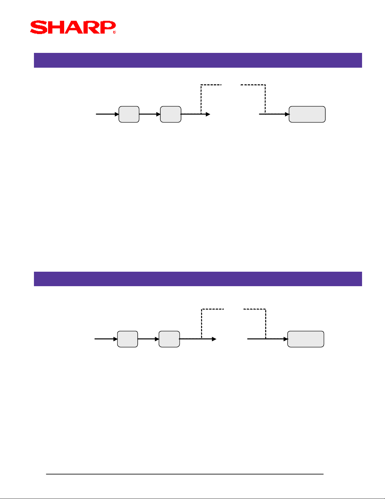
2. Master Reset-1 Operations:
There are 2 possible procedures to use in performing a Master Reset-1 operation.
Procedure-A: 1) Place the mode switch to the SRV' position
2) Place the AC power cord into the wall outlet
3) Depress and hould the [JOURNAL] feed key
4) Turn the mode switch from SRV' --> SRV position
Procedure-B: 1) Remove the AC power cord from the outlet
2) Place the mode switch to the SRV position
3) Depress and hold the [JOURNAL] feed key
4) Replace the AC power cord into the wall outlet
SRV
SRV’
*** Procedure A must be used to reset the hardware. Procedures B cannot reset the hardware.
Designs and specifications are subject to change without notice.
intro/ ii
Page 4

SRV Mode
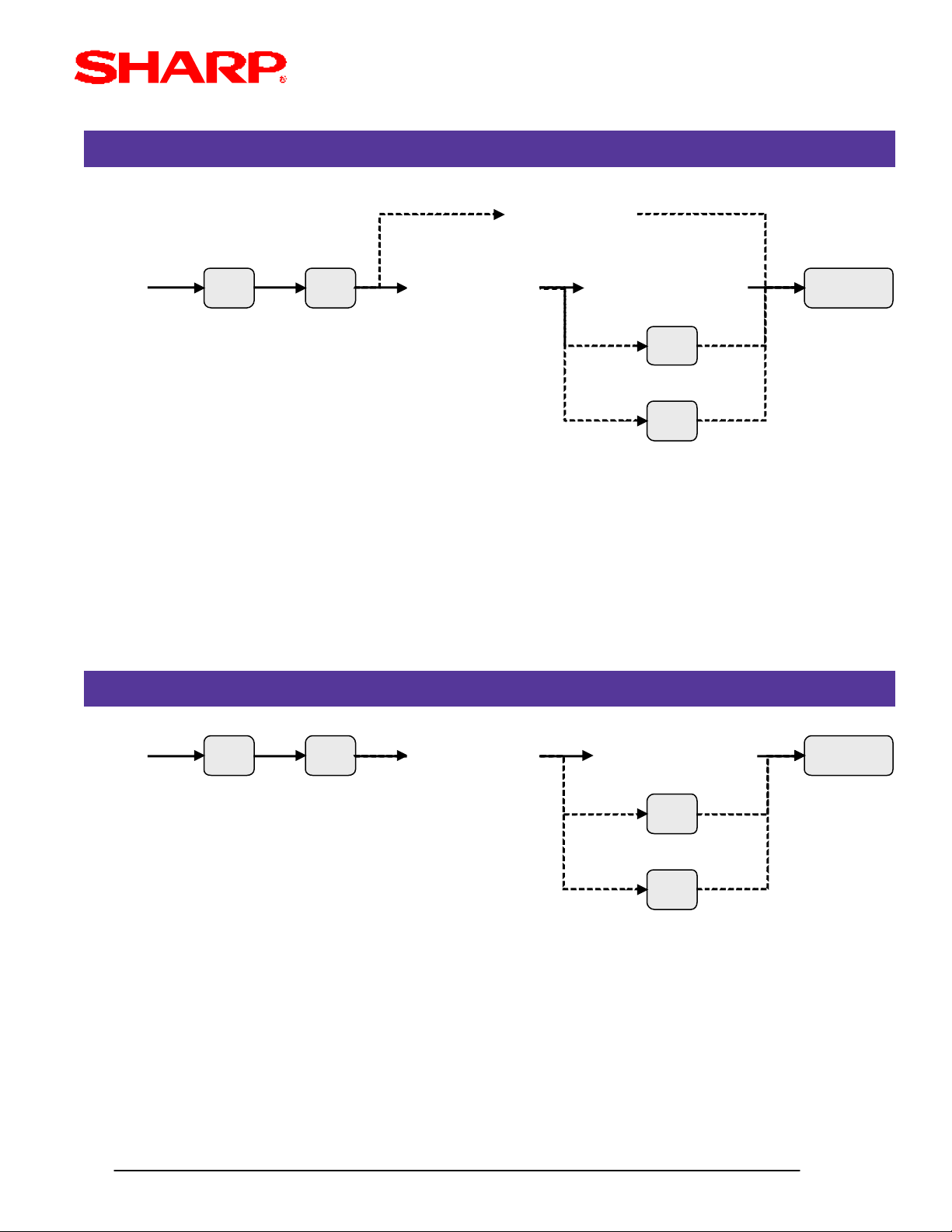
3. Master Reset-2 Operations:
There are 2 possible procedures to use in performing a Master Reset-2 operation.
Procedure-A: 1) Place the mode switch to the SRV' position
2) Place the AC power cord into the wall outlet
3) Depress and hold the [JOURNAL] & [RECEIPT] feed keys
4) Turn the mode switch from SRV' --> SRV position
*** The operator display will show the fixed function keys (starting the [0] key).
5) Program the Function Keys by depressing the desired location(s).
6) Once the [CA/AT] key is placed on the keyboard, *** MRS *** will be displayed
and the reset process will continue as outlined in Master Reset-1.
IMPORTANT NOTE:The Master Reset process is not complete unless the buzzer beeps 3 times.
Procedure-B: 1) Remove the AC power cord from the outlet
2) Place the mode switch to the SRV position
3) Depress and hold the [JOURNAL] & [RECEIPT] feed keys
4) Place the AC power cord into the wall outlet
SRV
SRV’
*** The operator display will show the fixed function keys (starting the [0] key).
5) Program the Function Keys by depressing the desired location(s).
6) Once the [CA/AT] key is placed on the keyboard, *** MRS *** will be displayed
and the reset process will continue as outlined in Master Reset-1.
*** Procedure A must be used to reset the hardware. Procedures B cannot reset the hardware.
Designs and specifications are subject to change without notice.
intro/ iii
Page 5

SRV Mode
PROGRAM RESETS
The Program Reset (sometimes refered to as a "Service Reset") may be achieved with and without a
[SRV] key (part no. LKGiM7113RCZZ) based on the System Preset settings.
1. General Rule:
A Program Reset should be performed under the following general conditions:
1) After the memory allocation setting has been modified
2) When a device assignment has been modified in COM port assignment
IMPORTANT NOTE:
During the Program Reset operation, PROGRAM RESET*** is printed on the journal tape.
2. Procedures:
Based on the SRV Job#928-B setting, there may be 3 possible procedures in performing a
Program Reset.
Procedure-A: 1) Place the mode switch to the SRV' position
2) Place the AC power cord into the wall outlet
3) Turn the mode switch from SRV' --> SRV position
SRV
SRV’
Procedure-B: 1) Remove the AC power cord from the outlet
2) Place the mode switch to the SRV' position
3) Replace the AC power cord into the wall outlet
4) Turn the mode switch clockwise to the SRV positionc(7o'clock).
Procedure-C: (based on SRV Job#928-B )
1) Remove the AC power cord from the wall outlet
2) Place the mode key in the PGM2 position
3) Depress and hold the [RECEIPT] & [JOURNAL] feed keys
4) Replace the AC power cord into the wall outlet while holding the keys
*** Procedure A must be used to reset the hardware. Procedures B and C cannot reset the
hardware.
Designs and specifications are subject to change without notice.
intro/ iv
Page 6
SRV Mode
.
RECOMMENDED SETUP PROCEDURE
To minimize unnecessary steps when installing the ER-A410 and ER-A420 model cash register,
please perform Job#975 (Memory Allocation), Job#900s (Service Parameter), Job#950 (Free Key),
Job #951 (Key No.) followed by "All" PGM2 settings.
The below chart represents the SRV Job# Reference Descriptions:
Job# Service Programming Description
900-929,
980
930-939 Report Counters (Z)
942-943,
969
944 PGM2 Mode Secret Coce
948 Training Cashier Assignment
949 Training Mode Title Programming
System Parameters
GT counters
950 Keyboard Layout - Function keys
951 Keyboard Layout - Dept & PLU keys
975 Memory Allocation Programming
985 Euro Symbol Programming for the TM-295 Slip Printer
986 Domestic Currency Symbol Programming
987 Language Selection for Text Print
990 SSP Data
996, 998 ECR Data Receive/Send Function
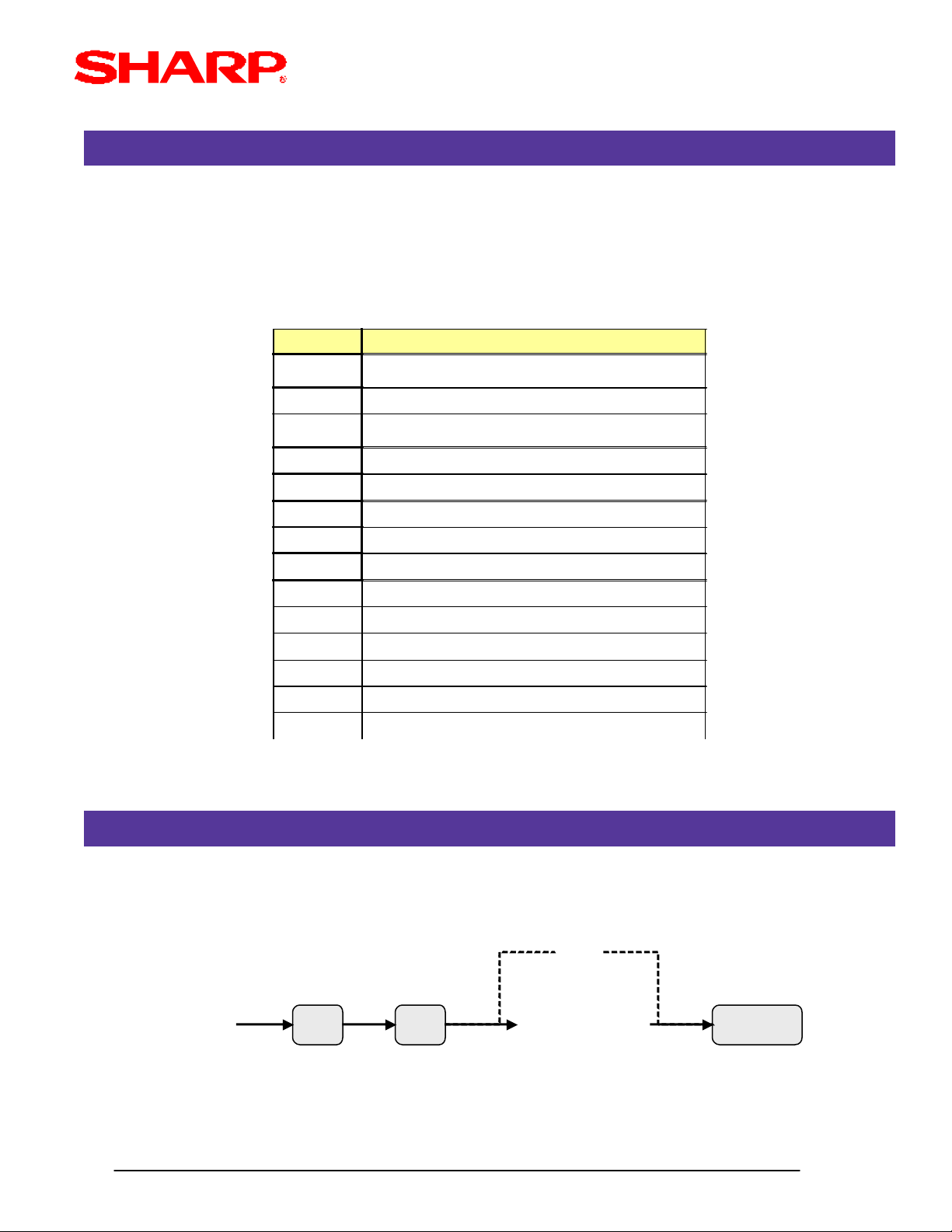
SERVICE MODE PROGRAMMING
Service mode programming is usually performed during the installation process. To change the
System Preset settings, the following key operation is required:
0
XXX
(Job#)
Designs and specifications are subject to change without notice.
@ CA/AT[A][B][C][D]
intro/ v
Page 7
SRV Mode
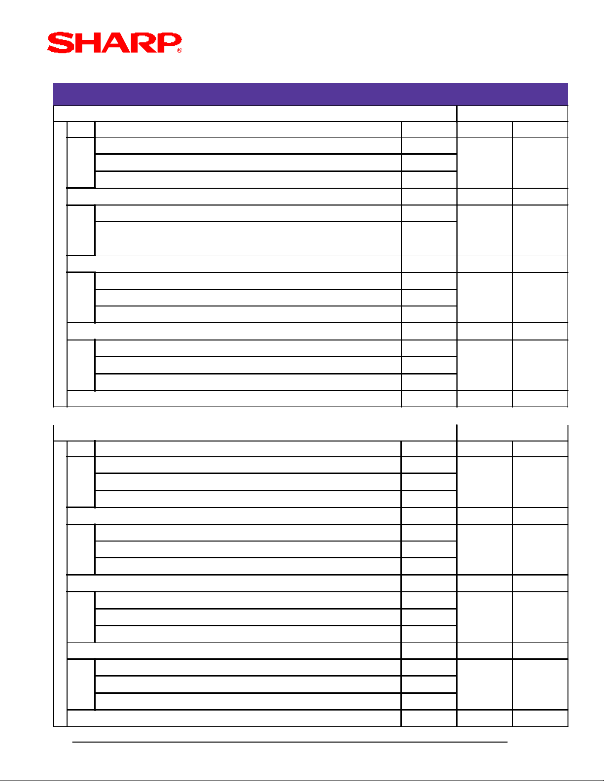
SYSTEM PRESETS
SRV Job# 901 MRS Defaults
Bit Description Data ER-A410 ER-A420
---- 4/0
A
---- 2/0
---- 1/0
SUM of Selection . . . . ^ --- 0 0
---- ---
B
Tax System:
Auto Tax1-4 & Manual Tax/Canadian Type-1-Type-10/Canadian Type-11 0/6/7
SUM of Selection . . . . ^ --- 0 0
---- ---
C
---- ---
Tax Rounding System: Singapore/Normal 8/0
SUM of Selection . . . . ^ 0 0
---- ---
D
---- ---
No. of Decimal Places for Tab 3/2/1/0
SUM of Selection . . . . ^ 2 2
SRV Job# 902 MRS Defaults
Bit Description Data ER-A410 ER-A420
---- 4/0
A
---- 2/0
---- 1/0
SUM of Selection . . . . ^ --- 0 0
---- 4/0
B
---- 2/0
---- 1/0
SUM of Selection . . . . ^ --- 0 0
---- 4/0
C
---- 2/0
---- 1/0
SUM of Selection . . . . ^ --- 0 0
---- 4/0
D
---- 2/0
---- 1/0
SUM of Selection . . . . ^ --- 0 0
Designs and specifications are subject to change without notice.
Page 1- 1
Page 8
SRV Mode
SYSTEM PRESETS
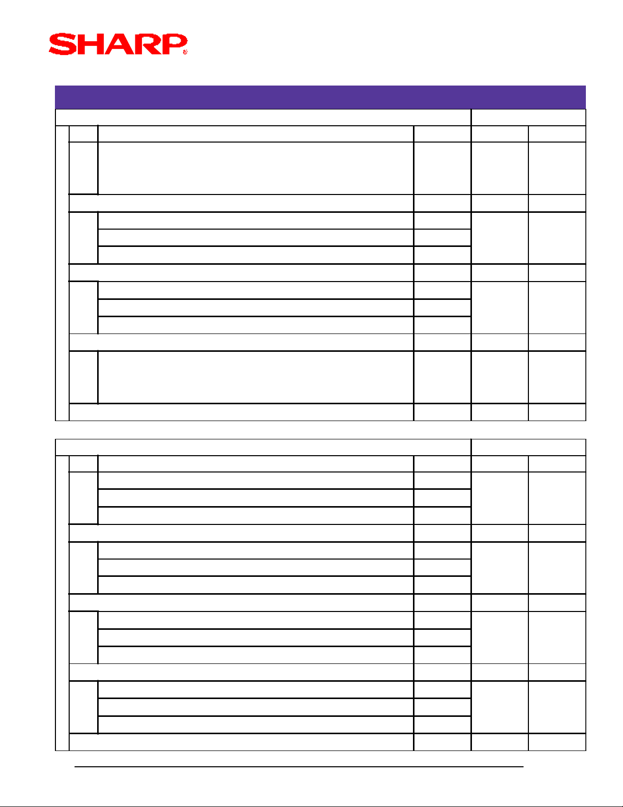
SRV Job# 903 MRS Defaults
Bit Description Data ER-A410 ER-A420
A ECR Data Copy (SIO) Baud Rate 19200 / 9600 5/4
SUM of Selection . . . . ^ 5 5
---- 4/0
B
Scale Entry Symbol "Kg"/"Lb" 2/0
---- 1/0
SUM of Selection . . . . ^ 0 0
---- 4/0
C
Tare Weight Entry is Allowed Yes/No 2/0
Unit of Weight for Scale 1ID+3DD / 2ID+2DD 1/0
SUM of Selection . . . . ^ 0 0
Food Stamp System:
D
Tax is Not Payable in Food Stamps / No Food Stamps
SUM of Selection . . . . ^ 0 0
SRV Job# 904 MRS Defaults
Bit Description Data ER-A410 ER-A420
Date is Printed No/yes 4/0
A
---- 2/0
---- 1/0
SUM of Selection . . . . ^ 0 0
Consecutive No. is Printed No/Yes 4/0
B
---- 2/0
---- 1/0
SUM of Selection . . . . ^ 0 0
---- 4/0
C
---- 2/0
---- 1/0
3/2/1/0Food Stamp Foregiveness / Tax Payable in Food Stamps /
SUM of Selection . . . . ^ --- 0 0
---- 4/0
D
---- 2/0
---- 1/0
SUM of Selection . . . . ^ --- 0 0
Designs and specifications are subject to change without notice.
Page 1- 2
Page 9
SRV Mode
SYSTEM PRESETS
SRV Job# 905 MRS Defaults
Bit Description Data ER-A410 ER-A420
Tax-4 Subtotal is printed on the (X/Z) Reports No/Yes 4/0
A
Gross & Refund Tax-4 Total is printed on (X/Z) Reports No/Yes 2/0
Net Tax-4 Total is printed on (X/Z) Reports No/Yes 1/0
SUM of Selection . . . . ^ 0 0
Tax is printed when the Taxable Subtotal is Zero (0.00) Yes/No 4/0
B
Tax is printed when the GST Tax is VAT No/Yes 2/0
Tax is printed when Tax is Zero (0.00) No/Yes 1/0
SUM of Selection . . . . ^ 0 0
GST EXPT is printed on (X/Z) Reports No/Yes 4/0
C
---- 2/0
---- 1/0
SUM of Selection . . . . ^ 0 0
Canadian Tax Method:
D
Type-10/Type-9/Type-8/Type-7/Type-6/Type-5/Type-4/
Type-3/Type-2/Type-1
SUM of Selection . . . . ^ 5 5
SRV Job# 906 MRS Defaults
Bit Description Data ER-A410 ER-A420
Dept. & PLU Codes are printed on the Receipt & Journal Yes/No 4/0
A
PLU Stock Indication upon Entry:
Inhibited/Operation Allowed w/ Display Inidicator/Allowed unconditionally
SUM of Selection . . . . ^ 0 0
Bottle Return Function is Enabled Yes/No 4/0
B
Hash Dept. is Enabled Yes/No 2/0
---- 1/0
SUM of Selection . . . . ^ 0 0
Split Price Counting Package/Qty 4/0
C
Multiplication Entry System:
Split Pricing/Successive Multiplication/Multiplication
SUM of Selection . . . . ^ 2 2
9/8/7/6/5/4/
3/2/1/0
2/1/0
2/0
1/0
---- 4/0
D
Presetting the Consecutive No. in PGM2 is Allowed No/Yes 2/0
Fractional Qty (3 digit decimal places) is enabled Yes/No 1/0
SUM of Selection . . . . ^ 0 0
Designs and specifications are subject to change without notice.
Page 1- 3
Page 10

SRV Mode
SYSTEM PRESETS
SRV Job# 907 MRS Defaults
Bit Description Data ER-A410 ER-A420
---- 4/0
A
---- 2/0
---- 1/0
SUM of Selection . . . . ^ --- 0 0
---- 4/0
B
---- 2/0
---- 1/0
SUM of Selection . . . . ^ --- 0 0
X Report is Enforced prior to Ind./All Cashier CCD Yes/No 4/0
C
---- 2/0
Minus Dept./PLU is Enabled Yes/No 1/0
SUM of Selection . . . . ^ 1 1
---- 4/0
D
Compulsory CCD: All Cashiers/Ind. Cashier/Non-Compulsory 2/1/0
SUM of Selection . . . . ^ 0 0
SRV Job# 908 MRS Defaults
Bit Description Data ER-A410 ER-A420
GT1 is printed on Z Report No/Yes 4/0
A
GT2 is printed on Z Report No/Yes 2/0
GT3 is printed on Z Report No/Yes 1/0
SUM of Selection . . . . ^ 0 0
GT1 is printed on X Report No/Yes 4/0
B
GT2 is printed on X Report No/Yes 2/0
GT3 is printed on X Report No/Yes 1/0
SUM of Selection . . . . ^ 0 0
Void Mode entries net the Hourly Sales Report Yes/No 4/0
C
X1/Z1 Reports may be taken in X2/Z2 mode No/Yes 2/0
Gen. Z1 Report resets the Consec. No. Yes/No 1/0
SUM of Selection . . . . ^ 0 0
(X/Z) Reports Print (except Ind. Cashier): Journal/Receipt & Journal 4/0
D
---- 2/0
Gen. Z1 resets the GT1/GT2/GT3 totals Yes/No 1/0
SUM of Selection . . . . ^ 0 0
Designs and specifications are subject to change without notice.
Page 1- 4
Page 11
SRV Mode
SYSTEM PRESETS
SRV Job# 909 MRS Defaults
Bit Description Data ER-A410 ER-A420
---- 4/0
A
Training GT prints on the Gen. X1 Report Yes/No 2/0
Training GT prints on the Gen Z1 Report No/Yes 1/0
SUM of Selection . . . . ^ 2 2
Data is printed when the PLU Z report is performed No/Yes 4/0
B
---- 2/0
---- 1/0
SUM of Selection . . . . ^ 0 0
VOID mode & MGR VOID are printed on the Gen. Z2 No/Yes 4/0
C
VOID mode & MGR VOID are printed on the Gen. Z1 No/Yes 2/0
---- 1/0
SUM of Selection . . . . ^ 0 0
---- 4/0
D
---- 2/0
---- 1/0
SUM of Selection . . . . ^ --- 0 0
SRV Job# 910 MRS Defaults
Bit Description Data ER-A410 ER-A420
---- 4/0
A
---- 2/0
---- 1/0
SUM of Selection . . . . ^ --- 0 0
---- 4/0
B
Cashier Code is Displayed/Printed Yes/No 2/0
Cashier Sign on System: Auto Sign-Off/Stay-Down 1/0
SUM of Selection . . . . ^ 2 2
---- 4/0
C
---- 2/0
---- 1/0
SUM of Selection . . . . ^ --- 0 0
---- 4/0
D
---- 2/0
(Fixed) 1/0
SUM of Selection . . . . ^ --- 4 4
Designs and specifications are subject to change without notice.
Page 1- 5
Page 12

SRV Mode
SYSTEM PRESETS
SRV Job# 911 MRS Defaults
Bit Description Data ER-A410 ER-A420
---- 4/0
A
Fraction Treatment:
---- 4/0
B
---- 2/0
---- 1/0
---- 4/0
C
---- 2/0
---- 1/0
Disregard/Rounding Up/Rounding Off
SUM of Selection . . . . ^ 0 0
SUM of Selection . . . . ^ --- 0 0
SUM of Selection . . . . ^ --- 0 0
2/1/0
---- 4/0
D
---- 2/0
---- 1/0
SUM of Selection . . . . ^ --- 0 0
SRV Job# 912 MRS Defaults
Bit Description Data ER-A410 ER-A420
---- 4/0
A
Date Print Format: Y-M-D/D-M-Y/M-D-Y 2/1/0
SUM of Selection . . . . ^ 0 0
---- 4/0
B
---- 2/0
Time System: 24-Hour/12-Hour 1/0
SUM of Selection . . . . ^ 0 0
Receipt After Contents: Detailed/Totals only 4/0
C
Receipt Copy Function is Enabled Yes/No 2/0
Footer Print Control: by each Media key preset/All Receipts 1/0
SUM of Selection . . . . ^ --- 6 6
Logo Message Control:
D
6-Line Header/STAMP & 3-Line Footer/3-Line Header & 3-Line Footer 3/4/5
3-Line Header only/STAMP only/STAMP & 3-Line Footer/ 0/1/2/
SUM of Selection . . . . ^ 0 0
Designs and specifications are subject to change without notice.
Page 1- 6
Page 13

SRV Mode
SYSTEM PRESETS
SRV Job# 913 MRS Defaults
Bit Description Data ER-A410 ER-A420
---- 4/0
A
---- 2/0
VP Total Amount contains: Tendered Amount/Total Amount 1/0
SUM of Selection . . . . ^ 0 0
Taxable Subtotal is printed when depressed Yes/No 4/0
B
MDSE Subtotal is printed when depressed Yes/No 2/0
Escape Function is Enabled for Comp. VP & Slip Yes/No 1/0
SUM of Selection . . . . ^ 1 1
---- 4/0
C
Error Beep System: until [CL] is depressed/for 2 seconds 2/0
Keyboard Buffer is Enabled No/Yes 1/0
SUM of Selection . . . . ^ 0 0
Comp. Drawer Closed before entry Yes/No 4/0
D
Error System: Misoperation is displayed/One-Shot error beep 2/0
Key Touch Sound is enabled No/Yes 1/0
SUM of Selection . . . . ^ 4 4
SRV Job# 914 MRS Defaults
Bit Description Data ER-A410 ER-A420
Receipt is issued for the [No Sale] function No/Yes 4/0
A
[NS] key is separated from the [CA/AT/NS] function No/Yes 2/0
Tax Delete function is Enabled Yes/No 1/0
SUM of Selection . . . . ^ 1 1
---- 4/0
B
---- 2/0
[No Sale] entry is allowed after a Non-Add [#] entry is made Yes/No 1/0
SUM of Selection . . . . ^ 1 1
---- 4/0
C
VOID-mode entries are Allowed No/Yes 2/0
Non-Add [#] Entry is Comp. for Sales Transactions (beginning) Yes/No 1/0
SUM of Selection . . . . ^ 0 0
Manual Tax function is Enabled No/Yes 4/0
D
Check Cashing function is Enabled Yes/No 2/0
Non-Add [#] function is Enabled No/Yes 1/0
SUM of Selection . . . . ^ 0 0
Designs and specifications are subject to change without notice.
Page 1- 7
Page 14
SRV Mode
SYSTEM PRESETS
SRV Job# 915 MRS Defaults
Bit Description Data ER-A410 ER-A420
---- 4/0
A
Fraction Treatment:
---- 4/0
B
---- 2/0
---- 1/0
---- 4/0
C
No. Times a SBTL (-)/(%) may be Entered Once/Any No. Times 2/0
---- 1/0
Disregard/Rounding Up/Rounding Off
SUM of Selection . . . . ^ 0 0
SUM of Selection . . . . ^ 0 0
SUM of Selection . . . . ^ 0 0
2/1/0
---- 4/0
D
---- 2/0
---- 1/0
SUM of Selection . . . . ^ 0 0
SRV Job# 916 MRS Defaults
Bit Description Data ER-A410 ER-A420
---- 4/0
A
---- 2/0
Item Text is truncated when unit price overlaps on 1-Line No/Yes 1/0
SUM of Selection . . . . ^ 1 1
Finalization through [CHG] media when SBTL = 0.00 Yes/No 4/0
B
---- 2/0
Food Stamp SBTL is Comp. before Tendering Yes/No 1/0
SUM of Selection . . . . ^ 4 4
MDSE (merchandise subtotal) may go negative No/Yes 4/0
C
Comp. [SBTL] before Amount-Tendering Entry Yes/No 2/0
Comp. [SBTL] before Direct-Tendering Entry Yes/No 1/0
SUM of Selection . . . . ^ 0 0
Coupon PLU Totalizer is printed on the Gen. (X/Z) Report No/Yes 4/0
D
Net Sales Subtotal (NET1) is printed on the Gen. (X/Z) Report No/Yes 2/0
Check Change Total is printed on the Gen. (X/Z) Report No/Yes 1/0
SUM of Selection . . . . ^ 0 0
Designs and specifications are subject to change without notice.
Page 1- 8
Page 15
SRV Mode
SYSTEM PRESETS
SRV Job# 917 MRS Defaults
Bit Description Data ER-A410 ER-A420
Taxable-1 SBTL prints on X/Z Report No/Yes 4/0
A
Gross & Refund Tax-1 prints on X/Z Report No/Yes 2/0
Net Tax-1 prints on X/Z Report No/Yes 1/0
SUM of Selection . . . . ^ 0 0
Taxable-2 SBTL prints on X/Z Report No/Yes 4/0
B
Gross & Refund Tax-2 prints on X/Z Report No/Yes 2/0
Net Tax-2 prints on X/Z Report No/Yes 1/0
SUM of Selection . . . . ^ 0 0
Taxable-3 SBTL prints on X/Z Report No/Yes 4/0
C
Gross & Refund Tax-3 prints on X/Z Report No/Yes 2/0
Net Tax-3 prints on X/Z Report No/Yes 1/0
SUM of Selection . . . . ^ 0 0
Total Tax prints on X/Z Report No/Yes 4/0
D
Gross Manual Tax and Refund Manual Tax prints on X/Z Report No/Yes 2/0
Net Manual Tax prints on X/Z Report No/Yes 1/0
SUM of Selection . . . . ^ 0 0
SRV Job# 918 MRS Defaults
Bit Description Data ER-A410 ER-A420
Text of a Set PLU is printed No/Yes 4/0
A
Direct Non-Tender entries is allowed for second tender entries Yes/No 2/0
---- 1/0
SUM of Selection . . . . ^ 2 2
---- 4/0
B
---- 2/0
Fractional Entries for non-Scalable Dept./PLU items is allowed No/Yes 1/0
SUM of Selection . . . . ^ 0 0
---- 4/0
C
---- 2/0
---- 1/0
SUM of Selection . . . . ^ ---- 0 0
---- 4/0
D
---- 2/0
---- 1/0
SUM of Selection . . . . ^ ---- 0 0
Designs and specifications are subject to change without notice.
Page 1- 9
Page 16

SRV Mode
SYSTEM PRESETS
SRV Job# 919 MRS Defaults
Bit Description Data ER-A410 ER-A420
---- 4/0
A
---- 2/0
---- 1/0
SUM of Selection . . . . ^ ---- 0 0
Cashier Code is checked upon Previous Balance Reorders No/Yes 4/0
B
---- 2/0
Previous Balance Number System Manual/Auto-Generate 1/0
SUM of Selection . . . . ^ 4 4
---- 4/0
C
Previous Balance Entry is Compulsory Yes/No 2/0
PLU Unit Price prints when it is $0.00 Yes/No 1/0
SUM of Selection . . . . ^ 0 0
Conversion SBTL is Printed with the Native SBTL No/Yes 4/0
D
---- 2/0
Foreign Currency Format includes Decimal Value Yes/No 1/0
SUM of Selection . . . . ^ ---- 0 0
SRV Job# 920 MRS Defaults
Bit Description Data ER-A410 ER-A420
---- 4/0
A
---- 2/0
---- 1/0
SUM of Selection . . . . ^ ---- 0 0
---- 4/0
B
---- 2/0
---- 1/0
SUM of Selection . . . . ^ ---- 0 0
---- 4/0
C
---- 2/0
---- 1/0
SUM of Selection . . . . ^ ---- 0 0
---- 4/0
D
---- 2/0
---- 1/0
SUM of Selection . . . . ^ ---- 0 0
Designs and specifications are subject to change without notice.
Page 1- 10
Page 17

SRV Mode
SYSTEM PRESETS
SRV Job# 921 MRS Defaults
Bit Description Data ER-A410 ER-A420
---- 4/0
A
---- 2/0
---- 1/0
SUM of Selection . . . . ^ ---- 0 0
---- 4/0
B
---- 2/0
---- 1/0
SUM of Selection . . . . ^ ---- 0 0
---- 4/0
C
---- 2/0
---- 1/0
SUM of Selection . . . . ^ ---- 0 0
---- 4/0
D
---- 2/0
---- 1/0
SUM of Selection . . . . ^ ---- 0 0
SRV Job# 922 MRS Defaults
Bit Description Data ER-A410 ER-A420
---- 4/0
A
---- 2/0
---- 1/0
SUM of Selection . . . . ^ ---- 0 0
---- 4/0
B
---- 2/0
---- 1/0
SUM of Selection . . . . ^ ---- 0 0
---- 4/0
C
---- 2/0
---- 1/0
SUM of Selection . . . . ^ ---- 0 0
---- 4/0
D
---- 2/0
---- 1/0
SUM of Selection . . . . ^ ---- 0 0
Designs and specifications are subject to change without notice.
Page 1- 11
Page 18

SRV Mode
SYSTEM PRESETS
SRV Job# 923 MRS Defaults
Bit Description Data ER-A410 ER-A420
---- 4/0
A
---- 2/0
---- 1/0
SUM of Selection . . . . ^ ---- 0 0
---- 4/0
B
---- 2/0
---- 1/0
SUM of Selection . . . . ^ ---- 0 0
---- 4/0
C
---- 2/0
---- 1/0
SUM of Selection . . . . ^ ---- 0 0
---- 4/0
D
---- 2/0
---- 1/0
SUM of Selection . . . . ^ ---- 0 0
SRV Job# 924 MRS Defaults
Bit Description Data ER-A410 ER-A420
---- 4/0
A
---- 2/0
---- 1/0
SUM of Selection . . . . ^ ---- 0 0
---- 4/0
B
---- 2/0
---- 1/0
SUM of Selection . . . . ^ ---- 0 0
---- 4/0
C
---- 2/0
---- 1/0
SUM of Selection . . . . ^ ---- 0 0
---- 4/0
D
---- 2/0
---- 1/0
SUM of Selection . . . . ^ ---- 0 0
Designs and specifications are subject to change without notice.
Page 1- 12
Page 19

SRV Mode
SYSTEM PRESETS
SRV Job# 925 MRS Defaults
Bit Description Data ER-A410 ER-A420
---- 4/0
A
---- 2/0
---- 1/0
SUM of Selection . . . . ^ ---- 0 0
---- 4/0
B
---- 2/0
---- 1/0
SUM of Selection . . . . ^ ---- 0 0
---- 4/0
C
---- 2/0
---- 1/0
SUM of Selection . . . . ^ ---- 0 0
---- 4/0
D
---- 2/0
---- 1/0
SUM of Selection . . . . ^ ---- 0 0
SRV Job# 926 MRS Defaults
Bit Description Data ER-A410 ER-A420
---- 4/0
A
---- 2/0
---- 1/0
SUM of Selection . . . . ^ ---- 0 0
Program Reset is enabled in PGM2 Mode Yes/No 4/0
B
---- 2/0
---- 1/0
SUM of Selection . . . . ^ 0 0
---- 4/0
C
---- 2/0
---- 1/0
SUM of Selection . . . . ^ ---- 0 0
---- 4/0
D
---- 2/0
---- 1/0
SUM of Selection . . . . ^ ---- 0 0
Designs and specifications are subject to change without notice.
Page 1- 13
Page 20
SRV Mode
SYSTEM PRESETS
SRV Job# 927 MRS Defaults
Bit Description Data ER-A410 ER-A420
---- 4/0
A
---- 2/0
---- 1/0
SUM of Selection . . . . ^ ---- 0 0
---- 4/0
B
---- 2/0
---- 1/0
SUM of Selection . . . . ^ ---- 0 0
---- 4/0
C
---- 2/0
---- 1/0
SUM of Selection . . . . ^ ---- 0 0
---- 4/0
D
---- 2/0
---- 1/0
SUM of Selection . . . . ^ ---- 0 0
SRV Job# 928 MRS Defaults
Bit Description Data ER-A410 ER-A420
---- 4/0
A
---- 2/0
Slip Logo Text is printed on Slip Printer Yes/No 1/0
SUM of Selection . . . . ^ 0 0
---- 4/0
B
Validation Message is printed on Slip for Checks & Charges Yes/No 2/0
Header Line is printed on Slip on Reorder Entries No/Yes 1/0
SUM of Selection . . . . ^ 0 0
$0.00 Priced PLU items print on Slip No/Yes 4/0
C
Set PLU Items are printed on Slip No/Yes 2/0
---- 1/0
SUM of Selection . . . . ^ 0 0
Prev. Bal/New Bal is printed on Slip No/Yes 4/0
D
Compulsory Slip Print System:
PB Entries only/Every Sale/Based on each Media Key Preset 2/1/0
SUM of Selection . . . . ^ 0 0
Designs and specifications are subject to change without notice.
Page 1- 14
Page 21

SRV Mode
SYSTEM PRESETS
SRV Job# 929 MRS Defaults
Bit Description Data ER-A410 ER-A420
---- 4/0
A
---- 2/0
---- 1/0
SUM of Selection . . . . ^ ---- 0 0
---- 4/0
B
---- 2/0
---- 1/0
SUM of Selection . . . . ^ ---- 0 0
---- 4/0
C
---- 2/0
---- 1/0
SUM of Selection . . . . ^ ---- 0 0
---- 4/0
D
---- 2/0
A Non-Taxable PLU is set Taxable by its Assoc. Dept. No/Yes 1/0
SUM of Selection . . . . ^ 0 0
SRV Job# 980 MRS Defaults
Bit Description Data ER-A410 ER-A420
---- 4/0
A
---- 2/0
PLU Stock Function is Enabled Yes/No 1/0
SUM of Selection . . . . ^ 0 0
---- 4/0
B
---- 2/0
Hash Dept. Entries are added to Hourly Sales Yes/No 1/0
SUM of Selection . . . . ^ 0 0
---- 4/0
C
---- 2/0
---- 1/0
SUM of Selection . . . . ^ ---- 0 0
---- 4/0
D
RCPT key is separate from the PO key Yes/No 2/0
PLU Price-2 is Enabled No/Yes 1/0
SUM of Selection . . . . ^ 0 0
Designs and specifications are subject to change without notice.
Page 1- 15
Page 22
RESET REPORT COUNTERS - Z1/Z2
SRV Mode
All Zeros
930
|
939
930: Z1 General Report Counter
933: Hourly Z1 Report Counter
934: PLU Z1 Report Counter
935: Cashier Z1 Report Counter
936: PBLU Z1 Report Counter
937: Z2 General Report Counter
939: Daily Net Z2 Report Counter
MRS = 0000
GRAND TOTAL PRESETS
.
@
XXXX
(4 digits)
CA/AT
All Zeros
942
943
944
942: GT2 (positive GT)
943: GT3 (negative GT)
969: Training GT
Note: The Net GT is obtained from GT2 and GT3 calculations
MRS = 0000000000000
Designs and specifications are subject to change without notice.
.
@
XXXXXXXXXXXXX
(13 digits)
CA/AT
Page 1- 16
Page 23
SECRET CODE PROGRAMMING
.
SRV Mode
All Zeros
944
XXXX: Secret Code
MRS = 0000
TRAINING CASHIER PROGRAMMING
.
@
XXXX
(4 digits)
CA/AT
948
XX : Cashier Code
MRS = 00
Designs and specifications are subject to change without notice.
@ CA/AT
0
XX
(2 digits)
Page 1- 17
Page 24
TRAINING MODE TITLE PROGRAMMING
.
12 Char.
.
SRV Mode
0
949
MRS = **TRAINING**
EURO SYMBOL PROGRAMMING
@ CA/AT
(Characters)
@ CA/ATX985
X: 0 = "spaces"
1 = Euro Symbol
MRS = 0 (spaces)
Designs and specifications are subject to change without notice.
0
Page 1- 18
Page 25
DOMESTIC CURRENCY SYMBOL
.
.
SRV Mode
0
986
MRS = ** $**
Note: The characters are entered using the programming key layout or by entering the
numeric codes shown on pg. 20. This symbol is printed with positive amounts of
domestic currency and will be printed to the left-side of the amount.
LANGUAGE SETTING FOR TEXT
@ CA/AT
(Characters)
4 Char.
@ CA/ATX987
X: 0 = English Text
1 = French Text
2 = Spanish Text
MRS = 0 (English)
Note: The following text is changed upon the setting above:
- FUNCTION text
- CASHIER text
- MESSAGE text (eg. Logo, etc.)
Designs and specifications are subject to change without notice.
0
Page 1- 19
Page 26
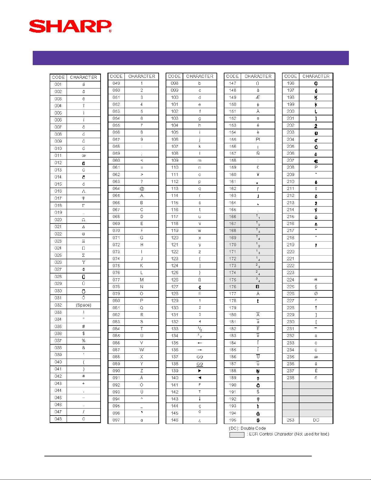
CHARACTER KEY CODES FOR TEXT PRINTING
SRV Mode
Designs and specifications are subject to change without notice.
Page 1- 20
Page 27
FUNCTION KEY LAYOUT
SRV Mode
MRS Defaults
.
XXX : Function No. 1-79
: 999 (for inhibiting a key)
MRS = Standard "out-of-the-box" key layout
Note: If the "fixed" function keys are accidentally placed in the wrong position, it may become
necessary to restore the MRS default keyboard in order to continue.
FUNCTION KEY LAYOUT
@ CA/AT(Key on Keyboard)950
XXX
(Function No.)
@
(Inhibits)
SBTL
(Advances to next Function)
.
XXX : 1-82 (ER-A410)
: 1-119 (ER-A420)
: 999 (for inhibiting a key)
MRS = Standard "out-of-the-box" key layout
Note: The Key No. programmed in this programming will be used in the PGM2 mode
programming for assigning direct Dept. and/or PLU keys to the keyboard.
Designs and specifications are subject to change without notice.
@ CA/AT(Key on Keyboard)951
XXX
(Key No.)
@
(Inhibits)
SBTL
(Advances to next Key No.)
Page 1- 21
Page 28
FUNCTION KEY REFERENCE CHART
1. ER-A410:
SRV Mode
2. ER-A420:
Note: The shaded keys are fixed and can not be modified in programming.
Designs and specifications are subject to change without notice.
Page 1- 22
Page 29
MEMORY ALLOCATION
SRV Mode
.
@ CA/ATYYYY975 @
X
(File No.)
X: see the Chart below
Y: see the Chart below
MRS = see the Chart below
Note: (1) The Maximum Number for "YYYY" can not be exceeded.
(2) The codes indicated are for PGM and REG mode operations
File Name X YYYY Codes
ER-A410 ER-A420
MRS Defaults
Departments 1 1 - 99 (Max) 2 - digits 20 10
PLU 2 0 - 1800 (Max) 6 - digits 500 500
PBLU 3 0 - 9999 (Max) 4 - digits 50 0
Cashier 4 1 - 20 (Max) 2 - digits 20 20
Designs and specifications are subject to change without notice.
Page 1- 23
Page 30
SSP DATA ENTRY
SRV Mode
990
.
XXX: Line No. Data
@
XXX
SSP Data
Next Line
SBTL
CA/AT
MRS = None
Note: The 1st Line No. entered represents the SSP #.
Note: The contents of the SSP Data entry is printed on the Receipt and Journal.
Note: If a "CHECK SUM ERROR" message is printed after the depression of the [CA/AT] key,
it will be necessary to review the contents against the provided bulletin and re-enter the
specific line no. data which has not been previously entered correctly by following the
procedure outlined for SRV Job#991 (next page).
IMPORTANT: A SERVICE RESET is required in order for the SSP data to take effect.
Designs and specifications are subject to change without notice.
Page 1- 24
Page 31

SSP DATA CORRECTION ENTRY
SRV Mode
991
XXX: Line No.
.
@
XXX
Line No.
Next Line
@
YYY
Line Data
SBTL
YYY: Corrected Line Data
Note: Enter each Line No. and the corrected data.
Note: Once all lines have been corrected, depress the [CA/AT] key. Verify that the "CHECK
SUM ERROR" message is not printed.
IMPORTANT: A SERVICE RESET is required in order for the SSP data to take effect.
CA/AT
Designs and specifications are subject to change without notice.
Page 1- 25
Page 32

900 Series Readings
SECTION - 6: ER02FD.EXE
PROGRAM READ OUTS
The following SRV mode programming print outs may be read from the ER-A410 and ER-A420:
Job#
Job#
900
900
950
950
951
951
990
990
SRV-mode System presets
SRV-mode System presets
SRV-mode Free Key Layout (only Function keys)
SRV-mode Free Key Layout (only Function keys)
SRV-mode Key Location Layout (only for Dept. & PLU assignment)
SRV-mode Key Location Layout (only for Dept. & PLU assignment)
SSP Data Report
SSP Data Report
Report Name
Report Name
Note: The above reports are printed on both the Receipt and Journal.
Designs and specifications are subject to change without notice.
Page 1- 26
Page 33

SYSTEM PRESETS READING - SRV MODE
1. Procedure:
1) Place the SRV key to the SRV-mode position.
2) Enter the following key sequence:
@ CA/AT900
2. Print Out:
900 Series Readings
Designs and specifications are subject to change without notice.
Page 1- 27
Page 34

FREE KEY LAY OUT READING - SRV MODE
1. Procedure:
1) Place the SRV key to the SRV-mode position.
2) Enter the following key sequence:
@ CA/AT950
2. Print Out:
900 Series Readings
Designs and specifications are subject to change without notice.
Page 1- 28
Page 35

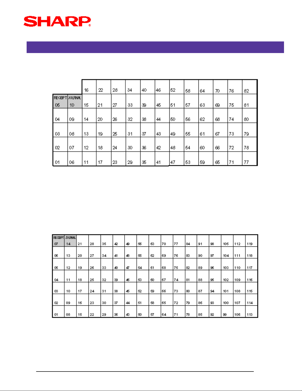
3. Keyboard No. Refernce:
1) Example from the ER-A410 Key No. Layout:
900 Series Readings
827670645852464034282216
827670645852464034282216
817569635751453933272115105
817569635751453933272115105
80746862565044383226201494
80746862565044383226201494
79736761554943373125191383
79736761554943373125191383
78726660544842363024181272
78726660544842363024181272
77716559534741352923171161
77716559534741352923171161
Note: The keys are fixed and can not be assigned to Key Functions
2) Example from the ER-A420 Key No. Layout:
119112105989184777063564942352821147
119112105989184777063564942352821147
118111104979083766962554841342720136
118111104979083766962554841342720136
117110103968982756861544740332619125
117110103968982756861544740332619125
116109102958881746760534639322518114
116109102958881746760534639322518114
115108101948780736659524538312417103
115108101948780736659524538312417103
11410710093867972655851443730231692
11410710093867972655851443730231692
Note: The keys are fixed and can not be assigned to Key Functions
Designs and specifications are subject to change without notice.
1131069992857871645750433629221581
1131069992857871645750433629221581
Page 1- 29
Page 36

4. Reference Free Keys to Keyboard:
1) Example from the ER-A410 default Key Layout:
NCPBLUFINAL
NCPBLUFINAL
@/FORJournalReceipt
RA
RA
#/TMSLIP
#/TMSLIP
RCPT/
RCPT/
PO
PO
%(-)
%(-)
RFNDVOID
RFNDVOID
@/FORJournalReceipt
CL
CL
.
.
987
987
654
654
321
321
PLU/SUB
PLU/SUB
SCALE
SCALE
900 Series Readings
OPEN
OPEN
TARE
TARE
TAX1
TAX1
SHFT
SHFT
TAX
TAX
CONV
CONV
SBTL
SBTL
CA/AT/NS000
CA/AT/NS000
CASH
CASH
827670645852464034282216
827670645852464034282216
FS
FS
SHIFT
SHIFT
817569635751453933272115105
817569635751453933272115105
FS
FS
TEND
TEND
80746862565044383226201494
80746862565044383226201494
CHCHK
CHCHK
79736761554943373125191383
79736761554943373125191383
SBTLMDSE
SBTLMDSE
78726660544842363024181272
78726660544842363024181272
77716559534741352923171161
77716559534741352923171161
#
#
Key No. Free Key Function
2) Example from the ER-A420 Default Key Layout:
JournalReceipt
JournalReceipt
PRICE
PRICE
SHIFT
SHIFT
@/FOR
@/FOR
#/TM
#/TM
.
.
000
000
L3L2L1
L3L2L1
SCALE
SCALE
CL
CL
987
987
654
654
321
321
SBTL
SBTL
AUTO
AUTO
/PO
/PO
CH2
CH2
CASH
CASH
#
#
119112105989184777063564942352821147
119112105989184777063564942352821147
RARCPT
RARCPT
118111104979083766962554841342720136
118111104979083766962554841342720136
(-)%
(-)%
117110103968982756861544740332619125
117110103968982756861544740332619125
VOIDRFND
VOIDRFND
116109102958881746760534639322518114
116109102958881746760534639322518114
TAX1
TAX1
SHFT
SHFT
115108101948780736659524538312417103
115108101948780736659524538312417103
CHKCH1
CHKCH1
11410710093867972655851443730231692
11410710093867972655851443730231692
CA/ATSBTLMDSE
CA/ATSBTLMDSE
1131069992857871645750433629221581
1131069992857871645750433629221581
Designs and specifications are subject to change without notice.
Key No. Free Key Function
Page 1- 30
Page 37

KEY LOCATION NO. READING
1. Procedure:
1) Place the SRV key to the SRV-mode position.
2) Enter the following key sequence:
@ CA/AT951
2. Print Out:
900 Series Readings
Designs and specifications are subject to change without notice.
Page 1- 31
Page 38

3. Reference to Key Locations to Keyboard:
1) Example from the ER-A410 default Key Layout:
NCPBLUFINAL
NCPBLUFINAL
@/FORJournalReceipt
RA
RA
#/TMSLIP
#/TMSLIP
RCPT/
RCPT/
PO
PO
%(-)
%(-)
RFNDVOID
RFNDVOID
@/FORJournalReceipt
CL
CL
.
.
987
987
654
654
321
321
000
000
PLU/SUB
PLU/SUB
SCALE
SCALE
900 Series Readings
OPEN
OPEN
TARE
TARE
171272
171272
161161
161161
TAX1
TAX1
SHFT
SHFT
827670645852464034282216
827670645852464034282216
TAX2015105
TAX2015105
817569635751453933272115105
817569635751453933272115105
CONV191494
CONV191494
80746862565044383226201494
80746862565044383226201494
79736761554943373125191383
79736761554943373125191383
SBTL
SBTL
78726660544842363024181272
78726660544842363024181272
CA/AT/NS
CA/AT/NS
77716559534741352923171161
77716559534741352923171161
CASH
CASH
#
#
FS
FS
SHIFT
SHIFT
FS
FS
TEND
TEND
CHCHK181383
CHCHK181383
SBTLMDSE
SBTLMDSE
Key No. Key Location No.
2) Example from the ER-A420 Default Key Layout:
JournalReceipt
JournalReceipt
621
621
5049
5049
3837
3837
2625
2625
1413
1413
21
21
82818079787776757473
82818079787776757473
PRICE
PRICE
#/TM
SHIFT
SHIFT
@/FOR
@/FOR
#/TM
72717069686766656463
72717069686766656463
60595857565554535251
60595857565554535251
48474645444342414039
48474645444342414039
36353433323130292827
36353433323130292827
24232221201918171615
24232221201918171615
1211109876543
1211109876543
L3L2L1
SCALE
SCALE
.
.
000
000
SBTL
SBTL
CL
CL
987
987
654
654
321
321
/PO
/PO
CH2
CH2
#
#
119112105989184777063564942352821147
119112105989184777063564942352821147
RARCPT
RARCPT
118111104979083766962554841342720136
118111104979083766962554841342720136
(-)%
(-)%
117110103968982756861544740332619125
117110103968982756861544740332619125
VOIDRFND
VOIDRFND
116109102958881746760534639322518114
116109102958881746760534639322518114
TAX1
TAX1
SHFT
SHFT
115108101948780736659524538312417103
115108101948780736659524538312417103
CHKCH1
CHKCH1
11410710093867972655851443730231692
11410710093867972655851443730231692
CA/ATSBTLMDSE
CA/ATSBTLMDSE
1131069992857871645750433629221581
1131069992857871645750433629221581
CASH
AUTO
CASH
AUTO
L3L2L1
Key No. Key Location No.
Designs and specifications are subject to change without notice.
Page 1- 32
Page 39

SSP DATA READING - SRV MODE
1. Procedure:
1) Place the SRV key to the SRV-mode position.
2) Enter the following key sequence:
@ CA/AT990
2. Print Out:
900 Series Readings
Designs and specifications are subject to change without notice.
Page 1- 33
Page 40

ROM VERSION AND SSP LIST READING - PGM2 MODE
1. Procedure:
1) Place the SRV or MGR key to the PGM2-mode position.
2) Enter the following key sequence:
@ CA/AT959
2. Example Receipt Print Out:
900 Series Readings
THANK YOU
YOUR RECEIPT
09/01/2002 9:30AM 0001
000001#0030
#0959 *PGM2*
27040RCC1A
RCC1A
Designs and specifications are subject to change without notice.
Page 1- 34
Page 41

RAM Data Copy Function
SECTION - 6: ER02FD.EXE
SECTION - 1: GENERAL OVERVIEW
The ER-A410 and ER-A420 model ECRs provide the ability to send/receive its RAM data for easy
storage or duplication.
1. Types of RAM data supported:
(1) SSP data (only) ........................................................... sending/receiving
(2) RAM image data (including SSP data) .................... sending/receiving
2. Functions Supported:
(1) ER-A410/ER-A420 to ER-A410/ER-A420
(2) ER-A410/ER-A420 to PC
(3) PC to ER-A410/ER-A420
3. Recommended Sequence:
(1) Always prepare the receiving equipment prior to initiating the sending device.
(2) Once the receiving equipment has been properly set, then invoke the sending device.
(3) Upon completion of receiving the RAM data it is necessary to perform a "Program Reset".
Designs and specifications are subject to change without notice.
Page 2- 1
Page 42

RAM Data Copy Function
CABLE & COMMUNICATIONS SPECIFICATIONS
The below diagram represents the cable specifications required when connecting the ER-A410 or
ER-A420 model ECR to another same type ECR. The same cable is also used when connecting
to a PC when the 02FD.exe program RAM Data Copy utiltiy used.
1. Specifications:
(1) Cable: 24-28AWG, Shielded, twisted pair - (example: Belden no. 8134)
(2) Connector: D-Sub 9 pin (female type) connector
(3) Baud Rates: 19200, 9600, 4800, 2400, 1200
2. Pin Outs:
When connecting the ER-A410/ER-A420 to another ER-A410/ER-A420 or PC, please refer to
the diagram below for the connection pin out diagram.
ECR
9-pin DSub
SD
3
RD
2
RTS
7
1
DCD
DTR
4
DSR
6
CTS
8
SG
5
9 Not Used
CI
SD : Transmitted Data
RD : Received Data
DTR : Data Terminal Ready
DSR : Data Set Ready
RTS : Request to Send
DCD : Data Carrier Detector
CTS : Clear to Send
SG : Signal Ground
ECR
9-pin DSub
SD
3
RD
2
RTS
7
1
DCD
RTS
4
DSR
6
CTS
8
SG
5
CI9
Designs and specifications are subject to change without notice.
Page 2- 2
Page 43

RAM Data Copy Function
PROGRAM RESET PROCEDURES
1. Program (SRV) Reset:
To perform a Program Reset, the SRV key (p/n: LKGiM7113RCZZ) must be used. Please refer to
the mode switch positions when performing the below key sequence.
(1) Insert the SRV key and rotate counterclockwise to the 6 o'clock position to the SRV' position.
(Please note that the display goes out)
(2) Count for 5 seconds.
(3) Rotate the SRV key clockwise to the SRV (7 o'clock) position.
(Please note that the display becomes lit and ***PROGRAM RESET is printed on the journal printer)
MODE SWITCH POSITIONS
Failure to adhere to the above procedure may result in corrupt or broken RAM addressing
Designs and specifications are subject to change without notice.
Page 2- 3
Page 44

RAM Data Copy Function
SECTION - 2: ECR DATA SENDING/RECEIVING SETTINGS
The following table shows the related SRV-mode Job#s available for the ER-A410 and ER-A420
model ECRs when the ECR Data Copy Function is used.
ECR Data Send/Receive
Mode Job# Description
903-A ECR Data Function Baud Rate
SRV-Mode
996 Send ECR Data
998 Receive ECR Data
Note: Please note that the ECR Data Copy function is dedicated to CH-1.
Note: Please perform a Program Reset at the Receiving Machine when the data sending
function has successfully completed.
FUNCTION SEQUENCE
To insure successful operations please adhere to the following sequence
(1) Connect ECR-#1 (Sending) and ECR-#2 (Receiving) with the prescribed cable.
(2) At ECR-#2 (Receiving) enter the SRV Job# 998.
(3) At ECR-#1 (Sending) enter the SRV JOB#996.
(4) Verify successful completion of the Data Copy function.
(5) Perform a Program Reset at ECR #2 (Receivng).
Designs and specifications are subject to change without notice.
Page 2- 4
Page 45

RAM Data Copy Function
.
.
ECR DATA SEND - 996
SSP Data Only
0
@ CA/ATAll Data996
Note: The speed which the data is sent is determined by the SRV Job#903-A setting.
MRS = 19200 bps
Display Indication during Transmission
ECR DATA RECEIVE - 998
@ CA/AT998
Note: The speed which the data is received is determined by the SRV Job#903-A setting.
MRS = 19200 bps
Designs and specifications are subject to change without notice.
Page 2- 5
Page 46

RAM Data Copy Function
QUICK STEPS - ECR-TO-ECR DATA COPY
To quickly setup the ER-A410/ER-A420 to copy the RAM data from one unit to another, please
refer to the outlined procedure below:
Comments/ProcedureDescriptionNo.
Comments/ProcedureDescriptionNo.
CH-1 onlyConnect each ECRStep-1
CH-1 onlyConnect each ECRStep-1
903 à [.] à [@] à 5000 à [CA/AT] (for 19200)
903 à [.] à [@] à 5000 à [CA/AT] (for 19200)
Note: MRS default is 5000 (19200)
Note: MRS default is 5000 (19200)
998 à [.] à [@] à [CA/AT]
998 à [.] à [@] à [CA/AT]
996 à [.] à [@] à [CA/AT]
996 à [.] à [@] à [CA/AT]
Step-3
Step-3
Step-4
Step-4
SRV Job#903Step-2
SRV Job#903Step-2
Set the Receiving ECR
Set the Receiving ECR
SRV Job#998
SRV Job#998
Start the Sending ECR
Start the Sending ECR
SRV Job#996
SRV Job#996
Look at the Sending and Receiving ECR’s journal TapeVerify CompletionStep-5
Look at the Sending and Receiving ECR’s journal TapeVerify CompletionStep-5
Execute a PROGRAM RESET at the Receiving unitProgram ResetStep-6
Execute a PROGRAM RESET at the Receiving unitProgram ResetStep-6
Designs and specifications are subject to change without notice.
Page 2- 6
Page 47

RAM Data Copy Function
SECTION - 3: PREPARING THE PC - 02FD.EXE
The ER02FD.exe utility has been created to work within the Windows ® environment. This utility may
be used when backing up or restoring the ER-A410/ER-A420 program data. The following procedures
should be followed;
Step-1. Create the 02FD folder at the PC.
(1) Open the Windows Explorer program.
(2) Under File, select NEW, then FOLDER.
(3) Label the folder as 02FD (Fig. 1).
(4) Create the additional Sub-Folders if desired.
example:
- Create a Sub folder named ERA420DATA (Fig. 2)
(FIG. 1)
Step-2. Copy the 02FD.exe file to the 02FD folder (Fig.3).
Designs and specifications are subject to change without notice.
(FIG. 2)
(FIG. 3)
Page 2- 7
Page 48

RAM Data Copy Function
Step-3. At the PC, launch the ER02FD.exe application. (1) Using the mouse, select the [ SETTING ]
button (Fig. 5).
(FIG.4)
Step-4. Under settings, select the required Baud Rate, Protocol and Communications port (Fig. 6).
Note: The maximum baud rate is 19200 bps. For the Protocol setting, only the SIO (Manual) is an
eligible selection.
(FIG.5)
Step-5. Select the [OK] button to save the settings and return to the 02FD Main Menu.
Designs and specifications are subject to change without notice.
Page 2- 8
Page 49

RAM Data Copy Function
SECTION - 4: ECR TO PC SENDING/RECEIVING
Precaution:
Insure that the receiving ECR model is the same model as the sending model ECR.
Step-1. Connect the ER-A410/ER-A420 to the PC using the previously specified RS-232 cable.
(FIG.6)
Step-2. At the PC, select the [POS --> PC] button (Fig.7)
(FIG.7)
Step-3. Name the new program data to be saved (Fig. 8)
(FIG.8)
Designs and specifications are subject to change without notice.
Page 2- 9
Page 50

RAM Data Copy Function
.
Step-4. Click the [SAVE] button and the 02FD program will automatically begin the receive process
(Fig. 9).
(FIG.9)
Step-5. Place the ECR in the SRV mode position (7 o'clock position).
Step-6. Enter the Send ECR Data key sequence;
SSP Data Only
0
@ CA/ATAll Data996
Step-7. Verify the ECR Send Data successfully completed by verifying the journal tape print message.
Designs and specifications are subject to change without notice.
Page 2- 10
Page 51

RAM Data Copy Function
SECTION - 5: PC TO ECR SENDING/RECEIVING
Precaution:
Insure that the receiving ECR model is the same model as the sending model ECR.
Step-1. Connect the ER-A410/ER-A420 to the PC using the previously specified RS-232 cable.
(FIG.10)
Step-2. At the PC, select the [PC --> POS] button (Fig.11)
(FIG.11)
Step-3. Select theprogram data to be sent (Fig. 12)
(FIG.12)
Designs and specifications are subject to change without notice.
Page 2- 11
Page 52

RAM Data Copy Function
Step-4. Click the [OPEN] button and the 02FD program will automatically begin the send process
(Fig. 13).
(FIG.13)
Step-5. Place the ECR in the SRV mode position (7 o'clock position).
Step-6. Enter the Receive ECR Data key sequence;
.
Step-7. Verify the ECR Receive Data successfully completed by verifying the journal tape print
message.
@ CA/AT998
Designs and specifications are subject to change without notice.
Page 2- 12
Page 53

RAM Data Copy Function
SECTION-6: ERROR CODES
It is important to verify the successful completion of the RAM Data Copy function. However, in the
event that the ER-A410/ER-A420 results in an error at initiating the RAM Data Copying function or
during communications, please refer to the ERROR CODES to determine the cause.
1. Display error codes
(Please refer to the next page)
2. Correction procedure
Once the error code has resulted, then the following procedure is recommended;
(1) Depress the [ CL ] key.
(2) Determine the cause of the problem.
(3) Correct the problem.
(4) Retry the procedure as before.
3. Verification by Journal print
The successful communications message will be printed at the journal printer upon successful
completion of communications.
(1) Examples of successful messages;
08/07/2002 10:11PM 01
000001 #0022
#996 SEND OK
08/07/2002 10:11PM 01
000001 #0023
#998 RECEIVE OK
(2) Examples of error messages;
08/07/2002 10:13PM 01
000001 #0024
#996 COM. ERROR 08
08/07/2002 10:15PM 01
000001 #0025
#998 TIME OUT
Designs and specifications are subject to change without notice.
Page 2- 13
Page 54

RAM Data Copy Function
ERROR MESSAGES
After communicationsis terminated, one of the following messages is printed:
1. SEND Operation:
1) Normal termination of a "SEND" operation...
|#996 SEND OK | Job No./Message
2) Communication Error of a "SEND" operation...
|#996 COM. ERROR 01 | Job No./Error Message/Error Code
3) Time Out Error of a "SEND" operation...
|#996 TIME OUT | Job No./Error Message
2. RECEIVE Operation:
1) Normal termination of a "RECEIVE" operation...
|#998 RECEIVE OK | Job No./Message
2) Communication Error of a "SEND" operation...
|#998 COM. ERROR 01 | Job No./Error Message/Error Code
3) Data Error of a "SEND" operation...
|#998 DATA ERROR 15 | Job No./Error Message/Error Code
4) Time Out Error of a "SEND" operation...
|#998 TIME OUT | Job No./Error Message
3. Error Codes:
01 = ID No. Error (ID No. in IDENQ is not correct)
02 = Parity Error
03 = Check Sum Error
04 = Data Size Error
05 = Hardware Error
06 = Power Off Error
07 = Time Out Error
08 = DSR Off Error
11 = Transmit Data Size Error
12 = Block Sequence Error (Irregular Sequence No. has been received)
13 = NAK code Error (NAK code has been received)
15 = ECR Type Error (Models of the two ECRs is different)
Note: All Error Messages are Fixed
Designs and specifications are subject to change without notice.
Page 2- 14
Page 55

PGM Mode
OVERVIEW
The ER-A410 and ER-A420 generally consists of two types of programming that are managed by the
mode key.
1. PGM2-mode programming : PGM jobs that are 2xxx
2. PGM1-mode programming : PGM jobs that are 1xxx
NOTE: PGM-1 jobs (1xxx) may be performed in the PGM1 or PGM2 mode, where the PGM-2
jobs (2xxx) may only be performed in PGM2 mode.
The PGM2-mode programming is primarily used when installing the ECR and for maintaining select
presets intended only for managers/owners.
The PGM1-mode programming is intended for settings that change frequently.
1. Programming Sequence:
When installing the ER-A410 and ER-A420, it is recommended to follow the sequence outlined
below:
1) Department Settings: This should be structured towards the balancing procedures required
2) PLU Settings
3) Keyboard Assignment
4) Cashier Setings
5) Tax Rate
6) All other settings
IMPORTANT NOTE:
When using PC Link or installing peripherals such as the Slip printer, the sequence may vary.
The RS232 settings for PC-Link and peripheral connections will be described in a separate
section.
2. General Rule:
When making preset entries, the following rule will apply:
1) If an error occurs prior to completing the 1st valid preset entry, it is necessary to depress the
[CL] key and beginning the PGM Job# again from the beginning.
2) If an error occurs on second and subsequent preset entries, then depress the [CL] key and
re-enter the desired values.
Designs and specifications are subject to change without notice.
3-Intro/ i
Page 56

Departments
OVERVIEW
The following table shows the available PGM-mode programming jobs available for the ER-A410
and ER-A420 model ECRs.
PGM Job# Description
Departments
1110 Dept. Unit Price setting
2110 Dept. Type and Functions
2111 Dept. Status - Tax, Food Stamps, Sign
2112 Dept. HALO setting
2114 Dept. Text
2115 Dept. Commission Group
2116 Dept. Group
2119 Direct Key for Dept.
2180 Dept. Age Limitation
Note: The above chart is shown in numeric order and should not be confused with the actual
method recommended as: PGM Job#2110, PGM#2111, PGM#1110 then all others.
Designs and specifications are subject to change without notice.
Page 3- 1
Page 57

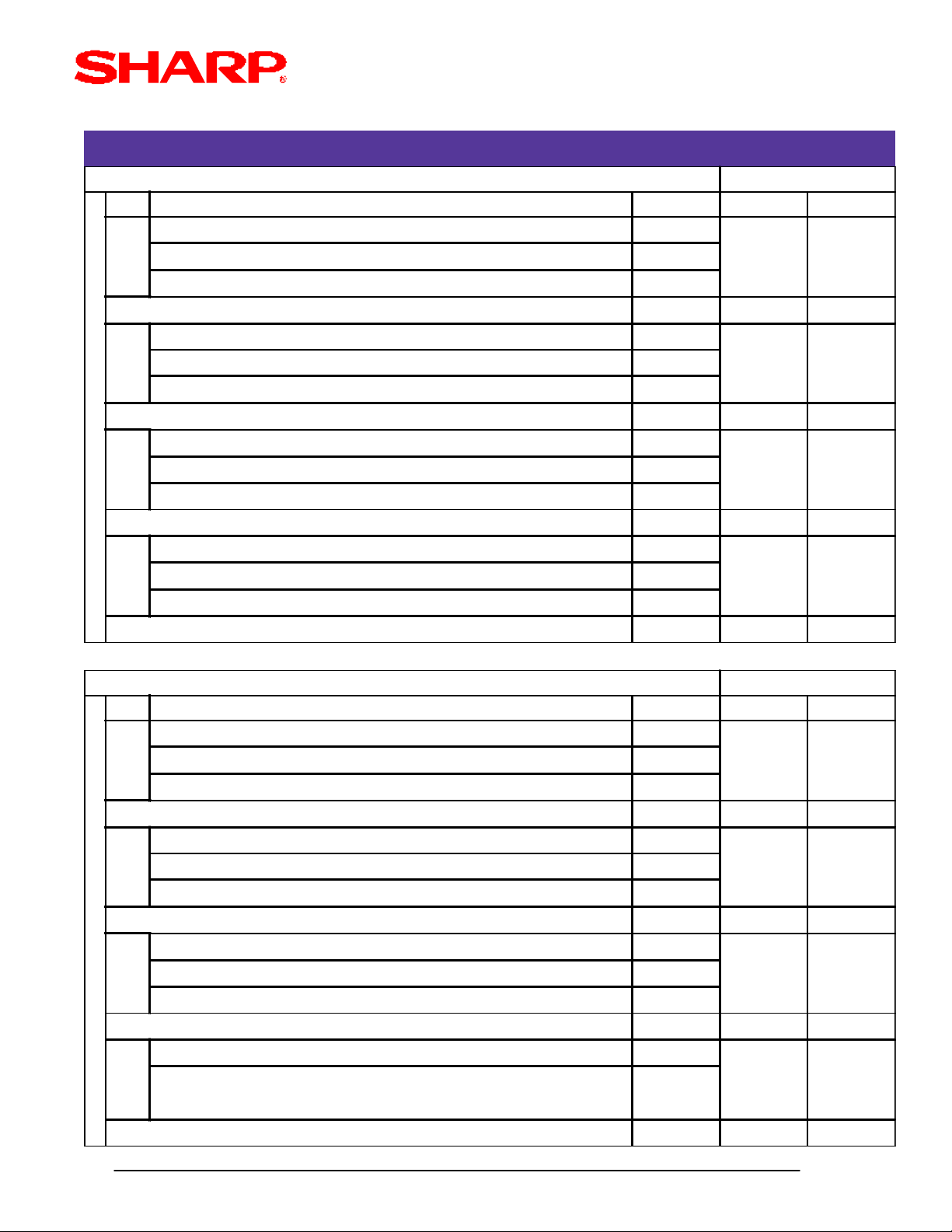
DEPARTMENT PRICE - 1110
Departments
1100
.
@
XX
Dept. Code
@
0
YYYYYY
(price)
SBTL
Next
Dept.Code
XX : Dept. Code 01-99
YYYYY : Unit Price (0-9999.99)
MRS = 0
Note: If a price is entered for a department which has been previously set as "Inhibited" or "Open" in PGM
Job#2110, then the type is changed as follows:"Inhibited" --> "Preset" and "Open" --> "Open & Preset"
DEPARTMENT TYPE - 2110
CA/AT
2110
.
XX : Dept. Code 01-99
ABCDEF : see below
A: Item Validation: Compulsory/Not 1/0
B: Tare Table No. Assignment: 1-9/0
C: Scale Entry: Compulsory/Enabled/Inhibit 2/1/0
D: SIF/SICS/Normal: 2/1/0
E: Bottle Return/Hash/Normal: 2/1/0
F: Amount Entry Type:
MRS = 000001
@
XX
Dept. Code
@
Open & Preset/Preset/Open/Inhibit 3/2/1/0
0
ABCDEF
Next
Dept.Code
SBTL
CA/AT
Designs and specifications are subject to change without notice.
Page 3- 2
Page 58

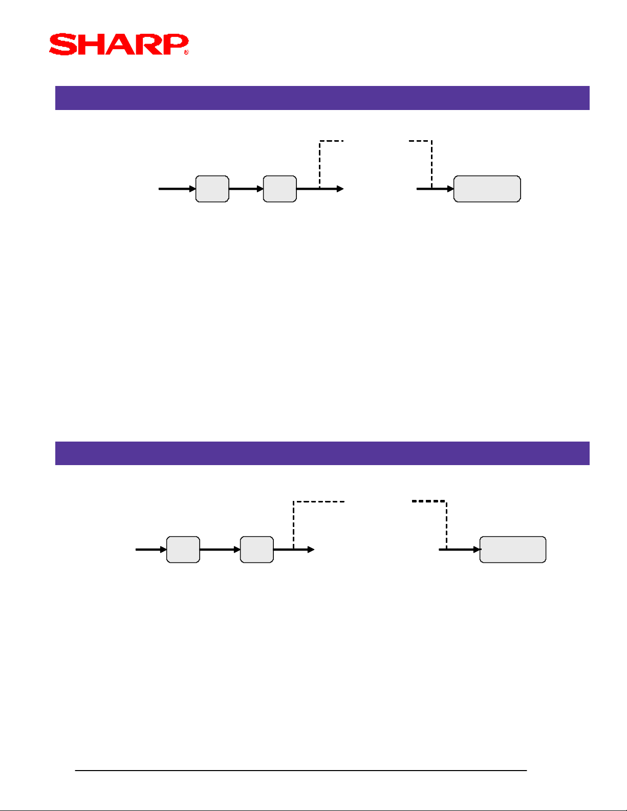
DEPARTMENT STATUS - 2111
Departments
2111
XX : Dept. Code 01-99
ABCDEF : see below
A: Sign -/+ 1/0
B: Food Stamp Eligible Yes/No 1/0
C: Taxable 4 Yes/No 1/0
D: Taxable 3 Yes/No 1/0
E: Taxable 2 Yes/No 1/0
F: Taxable 1 Yes/No 1/0
MRS = 000000
.
@
Dept. Code
DEPARTMENT HALO - 2112
XX
@
0
ABCDEF
Next
Dept.Code
SBTL
CA/AT
2112
XX : Dept. Code 01-99
AB : see below
A: Mantissa (0 - 9)
B: Exponent (0 - 7)
Note: Items A and B indicate A x 10B. (example: 17 = 10000000 or allows an entry up to 999999)
Any amount below that value will enabled within 99999999.
MRS = 17
.
@
XX
Dept. Code
@
0
AB
Dept.Code
SBTL
Next
CA/AT
Designs and specifications are subject to change without notice.
Page 3- 3
Page 59

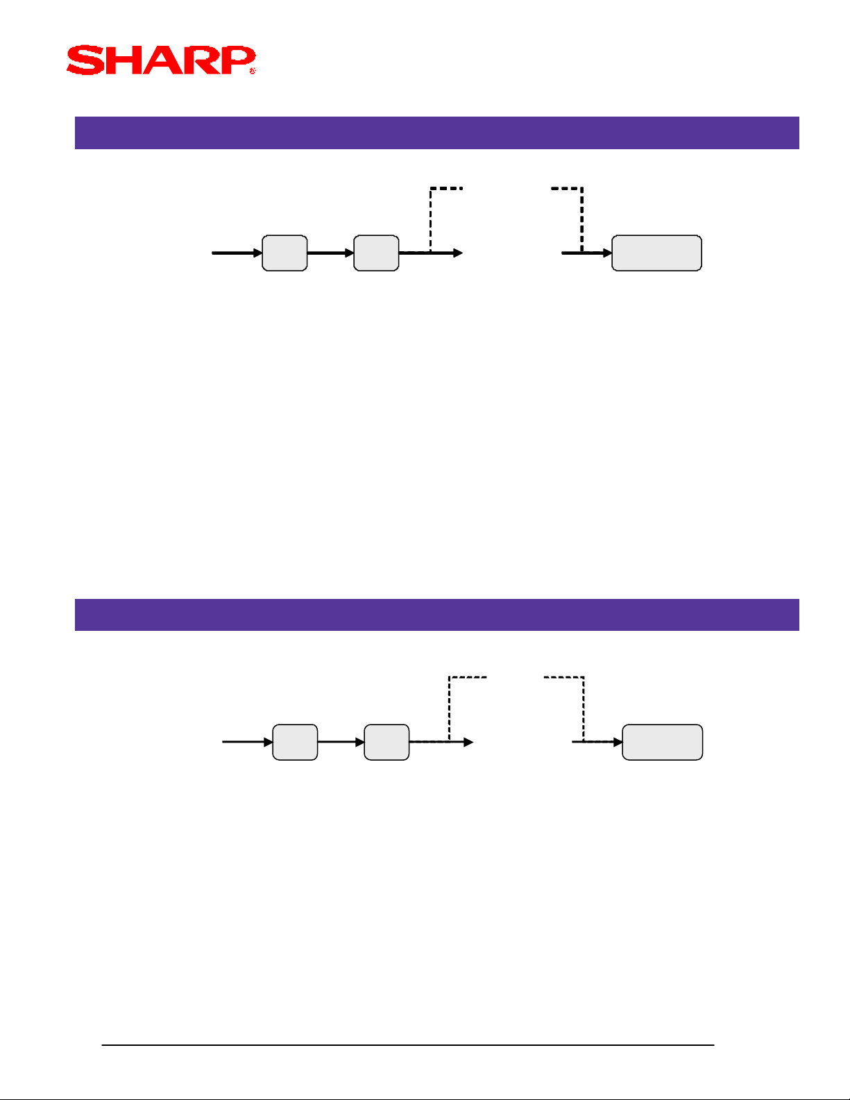
DEPARTMENT TEXT - 2114
Departments
2214
.
@
XXXXXX
PLU Code
@
No Change
Characters
(16 Char.)
PLU Code
SBTL
Next
XX : Dept. Code 01-99
Characters : Max. 16
Characters can be entered by using the character-keys or by character code entry. The key sequence for
entering character-codes is as follows:
XXX --> [00] key XXX : Character code (3 digits)
MRS = DPT.XX
DEPARTMENT COMMISSION GR OUP - 2115
CA/AT
2115
.
XX : Dept. Code 01-99
A : Group No. (0 - 9)
MRS = 0
@
XX
Dept. Code
@
0
A
Dept.Code
Next
SBTL
CA/AT
Designs and specifications are subject to change without notice.
Page 3- 4
Page 60

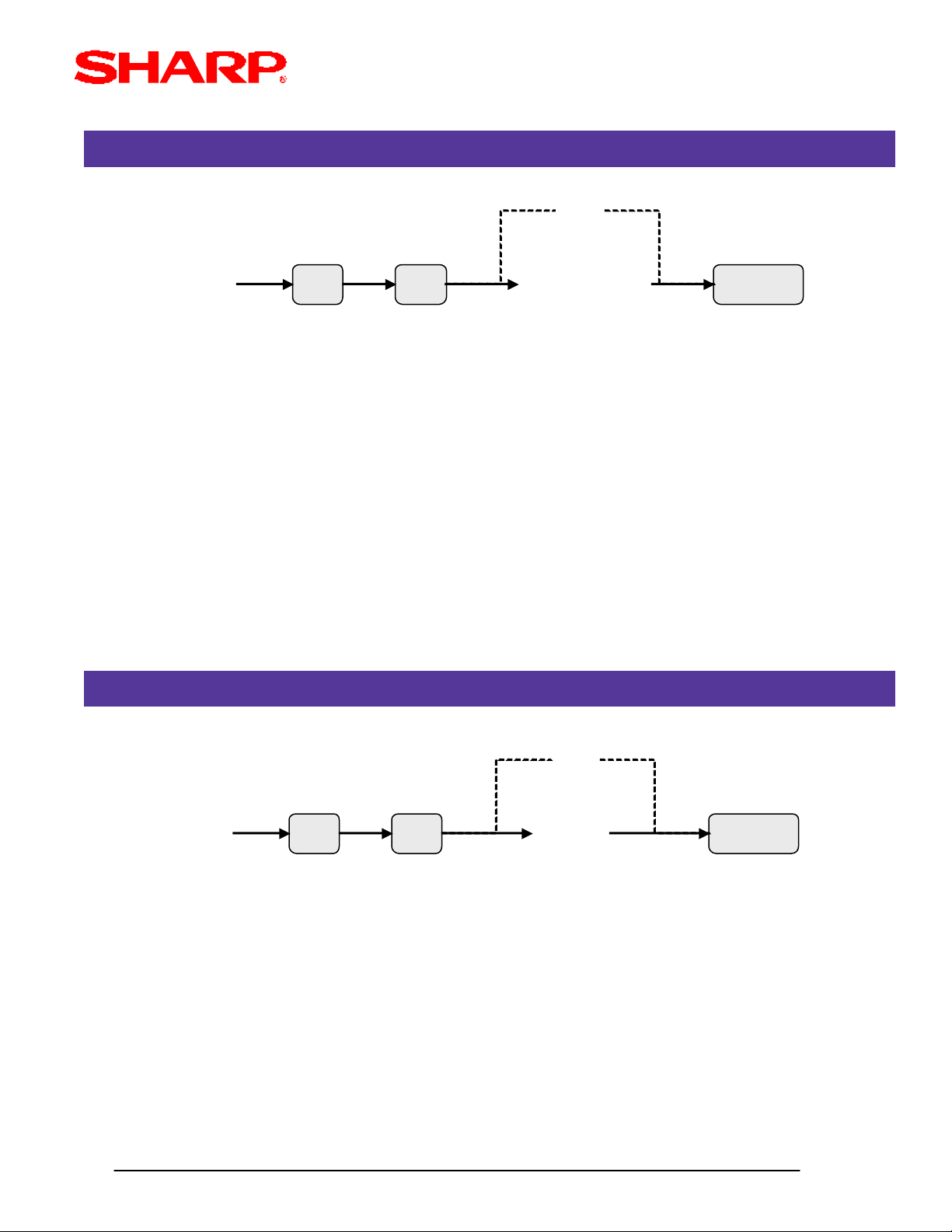
DEPARTMENT GR OUP - 2116
Departments
2116
.
@
XX
Dept. Code
XX : Dept. Code 01-99
A : see below
A: Dept. Group No. (0 - 9)
MRS = 0
DEPARTMENT DIRECT KEY ASSIGNMENT - 2119
@
0
A
Dept.Code
Next
SBTL
CA/AT
2119
.
@
XXX
Key No.
@
XXX : Key No.
YY : Dept. Code 01-99
MRS = Default Key Layout
X-Ref: The Key No. which has been previous programmed in SRV Job#951
Inhibit
YY
Next
Code
SBTL
CA/AT
Designs and specifications are subject to change without notice.
Page 3- 5
Page 61

DEPARTMENT AGE LIMITATION - 2180
Departments
2180
XX : Dept. Code 01-99
YY : see below
YY: Age (00 - 99) 00 = No limitation
MRS = 00
Note: The age is calculated in years against the date setting of the ECR.
X-Ref: The [BIRTHDAY] key must be preset in SRV Job#950
.
@
XX
Dept. Code
@
0
YY
Dept.Code
Next
SBTL
CA/AT
Designs and specifications are subject to change without notice.
Page 3- 6
Page 62

Price Look Up (PLU)
OVERVIEW
The following table shows the available PGM-mode programming jobs available for the ER-A410
and ER-A420 model ECRs for PLU items.
PGM Job# Description
PLU
1200 PLU Code Setup Programming
1210 PLU Unit Price Setting
1211 PLU Base Qty Setting
1220 PLU Stock Setting - Add
1221 PLU Stock Setting - Subtract
1222 PLU Stock Setting - Overwrite
2210 PLU Function Programmig
2211 PLU Status - Tax, Food Stamps, Sign
2214 PLU Text
2215 PLU Commission Group
2217 PLU Mix & Match Table Assignment
2219 Direct Key Assignment for PLU
2220 Link PLU Programming
2221 Set PLU Programming
2225 Mix & Match Table Setup
2280 PLU Age Limitation
Note: The above chart is shown in numeric order and should not be confused with the actual
method recommended as: PGM Job#1200, PGM#2211, PGM#1210 then all others.
Designs and specifications are subject to change without notice.
Page 3- 7
Page 63

PLU SETUP - 1200
Price Look Up (PLU)
1200
.
@
XXXXXX : PLU Code 1-999999
YY : Dept. Code 0 - 99
MRS = 01 (PLU codes 000001 - 000020 only)
PLU UNIT PRICE - 1210
XXXXXX
PLU Code
@
0
YY
Next
Code
SBTL
CA/AT
1210
.
@
XXXXXX
PLU Code
@
0
YYYYYY
Price-1
CL
Code
Next
SBTL
0
YYYYYY
Price- 2
SBTL
XXXXXX : PLU Code 1-999999
YYYYYY : Amount 0-999999
MRS = 000000
Note: If a price is entered for a PLU which has been previously set as "Inhibited" or "Open" in PGM
Job#1200, then the type is changed as follows:"Inhibited" --> "Preset" and "Open" --> "Open & Preset"
X-Ref: Price-2 is available when SRV Job# 980-D is set.
CA/AT
Designs and specifications are subject to change without notice.
Page 3- 8
Page 64

PLU BASE QTY - 1211
Price Look Up (PLU)
1211
XX : PLU Code 01-999999
ZZ : see below
ZZ: Base Qty (00 - 99) 00 = No limitation
MRS = 00
Note: If the PLU record is not in the PLU file during this programming, it will be created automatically upon
enteringa Base Qty.
X-Ref: SRV Job#980
.
@
XXXXXX
PLU Code
@
0
ZZ
SBTL
Next
Code
PLU STOCK (ADD) - 1220
CA/AT
1220
XXXXXX : PLU Code 1-999999
YYYYYYY : Stock Value (0-9999999)
MRS = 0000000
Note: The value entered is "added" to the existing Stock counter.
X-Ref: SRV Job#980
.
@
XXXXXX
PLU Code
@
YYYYYYY
Next
Code
SBTL
CA/AT
Designs and specifications are subject to change without notice.
Page 3- 9
Page 65

PLU STOCK (SUBTRACT) - 1221
Price Look Up (PLU)
1221
XXXXXX : PLU Code 1-999999
YYYYYYY : Stock Value (0-9999999)
MRS = 00
Note: The value entered is "subtracted" from the existing Stock counter.
X-Ref: SRV Job#980
.
@
XXXXXX
PLU Code
@
PLU STOCK (OVERWRITE) - 1222
YYYYYYY
Next
Code
SBTL
CA/AT
1222
XXXXXX : PLU Code 1-999999
YYYYYYY : Stock Value (0-9999999)
MRS = 0000000
Note: The value entered "over writes" to the existing Stock counter.
X-Ref: SRV Job#980
.
@
XXXXXX
PLU Code
@
0
YYYYYYY
Next
Code
SBTL
CA/AT
Designs and specifications are subject to change without notice.
Page 3- 10
Page 66

PLU FUNCTION - 2210
Price Look Up (PLU)
2210
XXXXXX : PLU Code 1-999999
ABC : see below
A: Tare Table No. Assignment: 9 to 1/0
B: Scale Entry: Compulsory/Enabled/Inhibit 2/1/0
C: Amount Entry Type:
MRS = 000001
Note: If the PLU record is not in the PLU file during this programming, it will be created automatically upon entry.
.
@
XXXXXX
PLU Code
Open & Preset/Preset/Open/Inhibit 3/2/1/0
@
0
ABC
Next
Code
SBTL
CA/AT
PLU STATUS - 2211
2211
XXXXXX : PLU Code 1-999999
ABCDEF : see below
A: Sign -/+ 1/0
B: Food Stamp Eligible Yes/No 1/0
C: Taxable 4 Yes/No 1/0
D: Taxable 3 Yes/No 1/0
E: Taxable 2 Yes/No 1/0
F: Taxable 1 Yes/No 1/0
MRS = 000000
Note: If the PLU record is not in the PLU file during this programming, it will be created automatically upon entry.
.
@
XXXXXX
PLU Code
@
0
ABCDEF
Next
Code
SBTL
CA/AT
Designs and specifications are subject to change without notice.
Page 3- 11
Page 67

PLU TEXT - 2214
Price Look Up (PLU)
2214
.
@
XXXXXX
PLU Code
@
No Change
Characters
(16 Char.)
PLU Code
Next
SBTL
CA/AT
XXXXXX : PLU Code 1-999999
Characters : Max. 16
Characters can be entered by using the character-keys or by character code entry. The key sequence for
entering character-codes is as follows:
XXX --> [00] key XXX : Character code (3 digits)
MRS = PLXXXXXX
Note: If the PLU record is not in the PLU file during this programming, it will be created automatically upon entry.
PLU COMMISSION GROUP - 2215
2215
.
@
XXXXXX
PLU Code
@
0
A
PLU Code
Next
SBTL
CA/AT
XXXXXX : PLU Code 1-999999
A : Group No. (0 - 9)
MRS = 0
Note: If the PLU record is not in the PLU file during this programming, it will be created automatically upon entry.
Designs and specifications are subject to change without notice.
Page 3- 12
Page 68

PLU MIX & MATCH - 2217
Price Look Up (PLU)
2217
XXXXXX : PLU Code 1-999999
ZZ : Mix & Match Tbl#
MRS = 00
Note: If the PLU record is not in the PLU file during this programming, it will be created automatically upon entry.
.
@
XXXXXX
PLU Code
@
No Change
ZZ
SBTL
CA/AT
PLU DIRECT KEY ASSIGNMENT - 2219
2219
XXX : Key No.
YYYYYY : PLU Code 1-999999
(*) : If a Level key is not depressed the 1st time, then Level-1 is programmed
The other PLU codes will follow the previous Level
MRS = Default Key Layout
X-Ref: The Key No. which has been previous programmed in SRV Job#951
.
@
(*)
L1
L2
L3
XX
Key No.
@
Inhibit
YYYYYY
(PLU Code)
Next
PLU Code
SBTL
CA/AT
Designs and specifications are subject to change without notice.
Page 3- 13
Page 69

LINK PLU - 2220
Price Look Up (PLU)
2220
.
@
XXXXXX
Parent Code
Delete or Skip
@
XXXXXX : Parent Code 1-999999
YYYYYY : Linked Code 1-999999
MRS = 0
Note: The parent code must be programmed prior to initiating this program job.
(*) : Pressing the [SBTL] key without entering "YYYYYY" will delete the previous settings
SET PLU - 2221
YYYYYYY
Max. 5
Times
SBTL
CA/AT
2221
.
@
XXXXXX
Parent Code
@
Delete or Skip
YYYYYYY
XXXXXX : Parent Code 1-999999
YYYYYY : Tied Code 1-999999
MRS = 0
Note: The parent code must be programmed prior to initiating this program job.
(*) : Pressing the [SBTL] key without entering "YYYYYY" will delete the previous settings
Max. 10
Times
SBTL
CA/AT
Designs and specifications are subject to change without notice.
Page 3- 14
Page 70

MIX & MATCH TABLE - 2225
Price Look Up (PLU)
2225
XX : Table No. 1-10
ZZ : Matching Count 1-99
YYYYYY : Adjustment Amount 1-999999
MRS = Nothing
.
@
PLU AGE LIMITATION - 2280
XX
Table No.
@
Delete
ZZ
SBTL
CA/AT
2280
XXXXXX : PLU Code 1-999999
YY : see below
YY: Age (00 - 99) 00 = No limitation
MRS = 00
Note: The age is calculated in years against the date setting of the ECR.
X-Ref: The [BIRTHDAY] key must be preset in SRV Job#950
.
@
XXXXXX
PLU Code
@
0
YY
PLU Code
Next
SBTL
CA/AT
Designs and specifications are subject to change without notice.
Page 3- 15
Page 71

PLU Range
OVERVIEW
The following table shows the available PGM-mode Range programming jobs available for the ERA410 and ER-A420 model ECRs for PLU items.
PGM Job# Description
PLU Range
2230 PLU Code Setup Programming
2231 PLU Function Programming
2332 PLU Status Programming - Tax, Food Stamps, Sign
2235 PLU Commission Group
2236 PLU Age Limitation
Note: The PLU Range programming job codes only change data for those PLU items which
already exist as a PLU code.
Designs and specifications are subject to change without notice.
Page 3- 16
Page 72

RANGE PLU SETUP - 2230
PLU Range
2230
XXXXXX : Starting PLU Code 1-999999
YYYYYY : Ending PLU Code 1-999999
ZZ : Dept. Code 1-99
Note: The Dept. code must be established in programming prior to this programming job.
.
@
XXXXXX
Start PLU Code
@
YYYYYY
End PLU Code
@
No Change
ZZ
RANGE PLU FUNCTONS - 2231
SBTL
CA/AT
2231
.
@
No Change
XXXXXX
Start PLU Code
XXXXXX : Starting PLU Code 1-999999
YYYYYY : Ending PLU Code 1-999999
ABC : A: Tare Table No. Assignment: 1-9/0
B: Scale Entry: Compulsory/Enabled/Inhibit 2/1/0
C: Amount Entry Type:
@
Open & Preset/Preset/Open/Inhibit 3/2/1/0
YYYYYY
End PLU Code
@
ABC
SBTL
CA/AT
Designs and specifications are subject to change without notice.
Page 3- 17
Page 73

RANGE PLU STATUS - 2232
PLU Range
2232
XXXXXX : Starting PLU Code 1-999999
YYYYYY : Ending PLU Code 1-999999
ABCDEF : A: Sign -/+ 1/0
.
B: Food Stamp Eligible Yes/No 1/0
C: Taxable 4 Yes/No 1/0
D: Taxable 3 Yes/No 1/0
E: Taxable 2 Yes/No 1/0
F: Taxable1 Yes/No 1/0
@
XXXXXX
Start PLU Code
@
YYYYYY
End PLU Code
RANGE PLU COMMISSION GROUP - 2235
@
No Change
ABCDEF
SBTL
CA/AT
2235
XXXXXX : Parent Code 1-999999
YYYYYY : Tied Code 1-999999
A : Group No. (0 - 9)
.
@
XXXXXX
Start PLU Code
@
YYYYYY
End PLU Code
@
No Change
A
SBTL
CA/AT
Designs and specifications are subject to change without notice.
Page 3- 18
Page 74

RANGE PLU AGE LIMITATION - 2236
PLU Range
2236
XXXXXX : Starting PLU Code 1-999999
YYYYYY : Ending PLU Code 1-999999
YY : Age (00-99) 00 = No Limitation
.
@
XXXXXX
Start PLU Code
@
YYYYYY
End PLU Code
@
No Change
YY
SBTL
CA/AT
Designs and specifications are subject to change without notice.
Page 3- 19
Page 75

Cashiers
OVERVIEW
The following table shows the available PGM-mode programming jobs available for the ER-A410
and ER-A420 model ECRs for setting up Cashiers.
PGM Job# Description
Cashiers
1500 Cashier Code Setting
1514 Cashier Text Programming
2510 Cashier Drawer Assignment
Designs and specifications are subject to change without notice.
Page 3- 20
Page 76

CASHIER CODE - 1500
Cashiers
1500
XX : Cashier No. (1-20)
YYYY : Cashier Code (1-9999)
MRS = Same code as the Cashier No.
.
XX
CASHIER TEXT - 1514
@
@
0
YYYY
SBTL
CA/AT
1514
YYYY : Cashier Code (1-9999)
Characters : Max. 8
Characters can be entered by using the character-keys or by character code entry. The key sequence for
entering character-codes is as follows:
XXX --> [00] key XXX : Character code (3 digits)
MRS = Spaces
.
@
YYYY
@
No Change
Characters
(Max. 8)
SBTL
CA/AT
Designs and specifications are subject to change without notice.
Page 3- 21
Page 77

CASHIER DRAWER ASSIGNMENT - 2510
Cashiers
2510
YYYY : Cashier Code (1-9999)
A : Not Open/Drawer-1/Drawer-2 0/1/2
MRS = 1
Note: A Drawer Assignment of "1" or "2" is required when a Coin Dispenser is connected.
.
@
YYYY
@
0
A
SBTL
CA/AT
Designs and specifications are subject to change without notice.
Page 3- 22
Page 78

Function & Media Keys
OVERVIEW
The following table shows the available PGM-mode programming jobs available for the ER-A410
and ER-A420 model ECRs for Functional keys.
PGM Job# Description
Function Keys
1310 Percent Rate Settings - (-), %, Conv., Commission
2311 (-), % Status Programming - Tax, Food Stamp, Sign
2312 Function Key HALO Setting - (-), Tax, RA, PO
2322 Media Key HALO Setting
2313 % Ket HALO Setting
2314 Function Text Programming
2315 % Key Type Programming - SBTL/Item
2316 (-) Type Programming - SBTL/Item
2320 Media Key Setup
2321 Media Key Function Programming -CID, Chk, Change, Ca/Chk
2326 Media Key Status Programming - Tax
2334 Currency Converion Text Programming
Designs and specifications are subject to change without notice.
Page 3- 23
Page 79

RATE PROGRAMMING - 1310
Function & Media Keys
1310
.
@
XXX : Function No. (see below)
YYYYYY : Price for (-)
YYY.YY : Rate for %
YYYY.YYYY : Rate for Conversion
YY.YYY : Rate for Commission
MRS = 0
(-) 11
(-) 11
(-) 22
(-) 22
(-) 33
(-) 33
(-) 44
(-) 44
% 15
% 15
% 26
% 26
% 37
% 37
% 48
% 48
Conv. 171
Conv. 171
Conv. 272 Rate0 to 9999.9999
Conv. 272 Rate0 to 9999.9999
Conv. 373
Conv. 373
Commission 1109
Commission 1109
Commission 2110
Commission 2110
Commission 3111
Commission 3111
Commission 4112
Commission 4112
Commission 5113
Commission 5113
Commission 6114
Commission 6114
Commission 7115
Commission 7115
Commission 8116
Commission 8116
Commission 9117
Commission 9117
XXX
Function No.
@
0
Rate or
Price
Unit Price0 to 999999
Unit Price0 to 999999
% Rate0 to 100.00
% Rate0 to 100.00
Rate0 to 999.99
Rate0 to 999.99
SBTL
RemarksEntry RangeFunctionNo.
RemarksEntry RangeFunctionNo.
CA/AT
Note: The decimal [.] key must be used to enter the rates and/or prices
Designs and specifications are subject to change without notice.
Page 3- 24
Page 80

MISC FUNCTION STATUS - 2311
Function & Media Keys
2311
XXX : Function No. (see below)
ABCDEF : A: Sign -/+ 1/0
MRS = 100000
.
B: Food Stamp Eligible Yes/No 1/0
C: Taxable 4 Yes/No 1/0
D: Taxable 3 Yes/No 1/0
E: Taxable 2 Yes/No 1/0
F: Taxable 1 Yes/No 1/0
@
XXX
Function No.
(-) 11
(-) 11
(-) 22
(-) 22
(-) 33
(-) 33
(-) 44
(-) 44
% 15
% 15
% 26
% 26
% 37
% 37
% 48
% 48
FunctionNo.
FunctionNo.
@
0
ABCDEF
SBTL
CA/AT
Designs and specifications are subject to change without notice.
Page 3- 25
Page 81

MISC FUNCTION HALO - 2312
Function & Media Keys
2312
XXX : Function No. (see below)
AB : A: Mantissa (0-9)
B: Exponent (0-7) for (-) and Tax
MRS = 17 for (-) and Tax
19 for RA/PO
18 for each Media Key
.
(0-9) for RA/PO
(0-8) for each Media Key
@
XXX
Function No.
@
0
AB
SBTL
CA/AT
1
1
2
2
3
3
4
4
64
64
65
65
66
66
67
67
(-) 1
(-) 1
(-) 2
(-) 2
(-) 3
(-) 3
(-) 4
(-) 4
RA
RA
RA2
RA2
PO
PO
PO2
PO2
Function
Function
FunctionNo.
FunctionNo.
Item B is specific within
Item B is specific within
the range 0 to 7
the range 0 to 7
Item B is specific within
Item B is specific within
the range 0 to 9
the range 0 to 9
Designs and specifications are subject to change without notice.
Page 3- 26
Page 82

MISC MEDIA HALO - 2322
Function & Media Keys
2322
XXX : Function No. (see below)
AB : A: Mantissa (0-9)
B: Exponent (0-7) for (-) and Tax
MRS = 17 for (-) and Tax
19 for RA/PO
18 for each Media Key
.
(0-9) for RA/PO
(0-8) for each Media Key
@
XXX
Function No.
@
0
AB
SBTL
CA/AT
61
61
62
62
76
76
78
78
82
82
84
84
86
86
87
87
CA1
CA1
CA 2
CA 2
CH1
CH1
CH2
CH2
CH380
CH380
CH4
CH4
CH5
CH5
CHK1
CHK1
CHK2
CHK2
Function
Function
FunctionNo.
FunctionNo.
Item B is specific within
Item B is specific within
the range 0 to 7
the range 0 to 7
Item B is specific within
Item B is specific within
the range 0 to 9
the range 0 to 9
Designs and specifications are subject to change without notice.
Page 3- 27
Page 83

MISC % HALO - 2313
Function & Media Keys
2313
XXX : Function No. (see below)
YYY.YY: % HALO
MRS = 0.00
.
@
XXX
Function No.
% 15
% 15
% 26
% 26
% 37
% 37
% 48
% 48
0
@
FunctionNo.
FunctionNo.
YYY.YY
SBTL
CA/AT
Designs and specifications are subject to change without notice.
Page 3- 28
Page 84

MISC MEDIA TEXT - 2314
Function & Media Keys
2314
.
@
No Change
XXX
Function No.
@
Characters
Max. 8
SBTL
XXX : Function No. (see below)
Characters : Max. 8
Characters can be entered by using the character-keys or by character code entry. The key sequence for
entering character-codes is as follows:
XXX --> [00] key XXX : Character code (3 digits)
MRS = see below
CA/AT
(-) 1
(-) 1
(-) 2
(-) 2
(-) 3
(-) 3
Function
Function
Default Text
Default Text
(-)1
(-)1
(-)2
(-)2
(-)3
(-)3
F-NO.F-NO.
F-NO.F-NO.
NET TAX2
NET TAX2
EXEMPT TAX2
EXEMPT TAX2
TAXABLE3 ST
TAXABLE3 ST
GROSS TAX3
GROSS TAX3
REFUND TAX3
REFUND TAX3
NET TAX3
NET TAX3
EXEMPT TAX3
EXEMPT TAX3
TAXABLE4 ST
TAXABLE4 ST
GROSS TAX4
GROSS TAX4
REFUND TAX4
REFUND TAX4
NET TAX4
NET TAX4
EXEMPT TAX4
EXEMPT TAX4
GROSS M-TAX
GROSS M-TAX
REFUND M-TAX
REFUND M-TAX
TAX2181
TAX2181
TX2 EXPT192
TX2 EXPT192
TAX3 ST203
TAX3 ST203
GRS TAX321(- )4(-) 44
GRS TAX321(- )4(-) 44
RFD TAX322%1% 15
RFD TAX322%1% 15
TAX323%2% 26
TAX323%2% 26
TX3 EXPT24%3% 37
TX3 EXPT24%3% 37
TAX4 ST25%4% 48
TAX4 ST25%4% 48
GRS TAX426NET1NET19
GRS TAX426NET1NET19
RFD TAX427TAX1 STTAXABLE1 ST10
RFD TAX427TAX1 STTAXABLE1 ST10
TAX428GRS TAX1GROSS TAX111
TAX428GRS TAX1GROSS TAX111
TX4 EXPT29RFD TAX1REFUND TAX112
TX4 EXPT29RFD TAX1REFUND TAX112
GRS MTAX30TAX1NET TAX113
GRS MTAX30TAX1NET TAX113
RFD MTAX31TX1 EXPTEXEMPT TAX114
RFD MTAX31TX1 EXPTEXEMPT TAX114
M-TAXNET M-TAX32TAX2 STTAXABLE2 ST15
M-TAXNET M-TAX32TAX2 STTAXABLE2 ST15
GST EXPTNON GST ST33GRS TAX2GROSS TAX216
GST EXPTNON GST ST33GRS TAX2GROSS TAX216
REFUND TAX2
REFUND TAX2
RFD TAX2
RFD TAX2
Designs and specifications are subject to change without notice.
PST TOTAL
PST TOTAL
PST TTL3417
PST TTL3417
Page 3- 29
Page 85

Function & Media Keys
Function
Function
GST TOTAL
GST TOTAL
FS1 FORGIVE
FS1 FORGIVE
FS2 FORGIVE
FS2 FORGIVE
Default Text
Default Text
GST TTL
GST TTL
FS TAX1
FS TAX1
FS TAX2
FS TAX2
Function
Function
BILL COUNTER
BILL COUNTER
DRAWER COUNT
DRAWER COUNT
TRAY TOTAL
TRAY TOTAL
PBAL
PBAL
SERVICE
SERVICE
DEPOSIT
DEPOSIT
DEPOSIT REFUND
DEPOSIT REFUND
TRANS COUNT
TRANS COUNT
NET3(SALES)
NET3(SALES)
CASH
CASH
CASH2
CASH2
FS SALE
FS SALE
REC ACCT
REC ACCT
REC ACCT2
REC ACCT2
Default TextF-NO.F-NO.
Default TextF-NO.F-NO.
BILL CNT5235
BILL CNT5235
DRW CNT5336
DRW CNT5336
TRAY TL5437
TRAY TL5437
***PBAL55FS TAX3FS3 FORGIVE38
***PBAL55FS TAX3FS3 FORGIVE38
SERVICE56TTL TAXTOTAL TAX-Report39
SERVICE56TTL TAXTOTAL TAX-Report39
DEPOSIT57NETNET40
DEPOSIT57NETNET40
DPST RF58NET2NET241
DPST RF58NET2NET241
TRANS CT59CP PLUCOUPON PLU42
TRANS CT59CP PLUCOUPON PLU42
NET360VOIDITEM VOID43
NET360VOIDITEM VOID43
CASH61SBTL VDSBTL VOID44
CASH61SBTL VDSBTL VOID44
CASH262MGR VDMANAGER VOID45
CASH262MGR VDMANAGER VOID45
FSSALE63VOIDVOID MODE46
FSSALE63VOIDVOID MODE46
***RA64REFUNDREFUND47
***RA64REFUNDREFUND47
***RA265HASH VDHASH VOID48
***RA265HASH VDHASH VOID48
***POPAID OUT66HASH RFHASH REFUND49
***POPAID OUT66HASH RFHASH REFUND49
***PO2PAID OUT267NO SALENO SALE50
***PO2PAID OUT267NO SALENO SALE50
VP COUNTER
VP COUNTER
Function
Function
CHECK CHANGE
CHECK CHANGE
FS CHANGE
FS CHANGE
CONVERSION1
CONVERSION1
VP CNT
VP CNT
Default Text
Default Text
CHK/CG
CHK/CG
FS/CG
FS/CG
CONV1
CONV1
CHECK CASHING
CHECK CASHING
Function
Function
CHECK1
CHECK1
CHECK2
CHECK2
CASH/CHECK ID
CASH/CHECK ID
CASH IN DRAWER
CASH IN DRAWER
VAT EXEMPT
VAT EXEMPT
AVERAGE-Hourly R.
AVERAGE-Hourly R.
GROUP1
GROUP1
GROUP2
GROUP2
GROUP3
GROUP3
GROUP4
GROUP4
GROUP5
GROUP5
GROUP6
GROUP6
GROUP7
GROUP7
GROUP8
GROUP8
CA/CHK6851
CA/CHK6851
Default TextF-NO.F-NO.
Default TextF-NO.F-NO.
CHECK18669
CHECK18669
CHECK28770
CHECK28770
CA/CH ID8871
CA/CH ID8871
***CID89CONV2CONVERSION272
***CID89CONV2CONVERSION272
VAT EXPT90CONV3CONVERSION373
VAT EXPT90CONV3CONVERSION373
AVE91CONV4CONVERSION474
AVE91CONV4CONVERSION474
GROUP192FS/IDFS IN DRAWER75
GROUP192FS/IDFS IN DRAWER75
GROUP293CHARGE1GROSS CHARGE176
GROUP293CHARGE1GROSS CHARGE176
GROUP394CHARGE1-REFUND CHARGE177
GROUP394CHARGE1-REFUND CHARGE177
GROUP495CHARGE2GROSS CHARGE278
GROUP495CHARGE2GROSS CHARGE278
GROUP596CHARGE2-REFUND CHARGE279
GROUP596CHARGE2-REFUND CHARGE279
GROUP697CHARGE3GROSS CHARGE380
GROUP697CHARGE3GROSS CHARGE380
GROUP798CHARGE3-REFUND CHARGE381
GROUP798CHARGE3-REFUND CHARGE381
GROUP899CHARGE4GROSS CHARGE482
GROUP899CHARGE4GROSS CHARGE482
REFUND CHARGE5
REFUND CHARGE5
CHARGE5-
CHARGE5-
Designs and specifications are subject to change without notice.
PLU PRICE2
PLU PRICE2
GROUP9GROUP9100CHARGE4-REFUND CHARGE483
GROUP9GROUP9100CHARGE4-REFUND CHARGE483
LEVEL1PLU PRICE1101CHARGE5GROSS CHARGE584
LEVEL1PLU PRICE1101CHARGE5GROSS CHARGE584
LEVEL210285
LEVEL210285
Page 3- 30
Page 86

Function & Media Keys
Function
Function
(+) DEPT TOTAL
(+) DEPT TOTAL
(-) DEPT TOTAL
(-) DEPT TOTAL
HASH (+) DEPT TL
HASH (+) DEPT TL
Default Text
Default Text
*DEPT TL
*DEPT TL
DEPT (-)
DEPT (-)
*HASH TL
*HASH TL
Function
Function
COMM AMOUNT2
COMM AMOUNT2
COMM AMOUNT3
COMM AMOUNT3
COMM AMOUNT4
COMM AMOUNT4
COMM AMOUNT5
COMM AMOUNT5
COMM AMOUNT6
COMM AMOUNT6
COMM AMOUNT7
COMM AMOUNT7
COMM AMOUNT8
COMM AMOUNT8
COMM AMOUNT9
COMM AMOUNT9
COMM AMT OTAL
COMM AMT OTAL
CASH/CHECK IS
CASH/CHECK IS
CONVERSION1 IS
CONVERSION1 IS
CONVERSION2 IS
CONVERSION2 IS
CONVERSION3 IS
CONVERSION3 IS
CCD DIFFER
CCD DIFFER
Default TextF -NO.F-NO.
Default TextF -NO.F-NO.
COM.AMT2120103
COM.AMT2120103
COM.AMT3121104
COM.AMT3121104
COM.AMT4122105
COM.AMT4122105
COM.AMT5123HASH ( -)HASH (-) DEPT TL106
COM.AMT5123HASH ( -)HASH (-) DEPT TL106
COM.AMT6124*BTTL TLBOTTLE (+) DEPT107
COM.AMT6124*BTTL TLBOTTLE (+) DEPT107
COM.AMT7125BTTL (-)BOTTLE (-) DEPT108
COM.AMT7125BTTL (-)BOTTLE (-) DEPT108
COM.AMT8126COM.SAL1COMM. SALE1109
COM.AMT8126COM.SAL1COMM. SALE1109
COM.AMT9127COM.SAL2COMM. SALE2110
COM.AMT9127COM.SAL2COMM. SALE2110
COM.TTL128COM.SAL3COMM.SALE3111
COM.TTL128COM.SAL3COMM.SALE3111
CA/CH IS129COM.SAL4COMM. SALE4112
CA/CH IS129COM.SAL4COMM. SALE4112
CONV1 IS130COM.SAL5COMM. SALE5113
CONV1 IS130COM.SAL5COMM. SALE5113
CONV2 IS131COM.SAL6COMM.SALE6114
CONV2 IS131COM.SAL6COMM.SALE6114
CONV3 IS132COM.SAL7COMM. SALE7115
CONV3 IS132COM.SAL7COMM. SALE7115
CCD DIF.133COM.SAL8COMM. SALE8116
CCD DIF.133COM.SAL8COMM. SALE8116
DIF. TLCCD DIFFER TTL134COM.SAL9COMM.SALE9117
DIF. TLCCD DIFFER TTL134COM.SAL9COMM.SALE9117
SUBTOTALSUBTOTAL135NON COM.NON COMM. SALE118
SUBTOTALSUBTOTAL135NON COM.NON COMM. SALE118
143
143
144
144
145
145
146
146
147
147
148
148
149
149
151
151
152
152
153
153
COMM AMOUNT1
COMM AMOUNT1
Function
Function
TOTAL
TOTAL
CHANGE
CHANGE
FS SBTL
FS SBTL
DEPT. REPORT
DEPT. REPORT
TITLE
TITLE
GROUP REPORT
GROUP REPORT
TITLE
TITLE
PLU REPORT
PLU REPORT
TITLE
TITLE
STOCK REPORT
STOCK REPORT
TITLE
TITLE
0 SALES REPORT
0 SALES REPORT
TITLE
TITLE
PRICE CATEGORY
PRICE CATEGORY
REPORT TITLE
REPORT TITLE
TRANS REPORT
TRANS REPORT
TITLE
TITLE
COMMISSION
COMMISSION
REPORT TITLE
REPORT TITLE
CCD REPORT
CCD REPORT
TITLE
TITLE
CASHIER REPORT
CASHIER REPORT
TITLE
TITLE
COM.AMT1
COM.AMT1
Default Text
Default Text
***TTL
***TTL
CHANGE
CHANGE
FS ST
FS ST
CASHIER
CASHIER
MDSE SBTL
MDSE SBTL
Function
Function
HOURLY REPORT
HOURLY REPORT
TITLE
TITLE
DAILY NET
DAILY NET
REPORT TITLE
REPORT TITLE
PBLU REPORT
PBLU REPORT
TITLE
TITLE
NON ADD CODE
NON ADD CODE
TEXT
TEXT
COPY RCPT TITLE
COPY RCPT TITLE
FINAL
FINAL
BALANCE
BALANCE
SLIP PRINT MSG
SLIP PRINT MSG
SLIP NEXT-PAGE
SLIP NEXT-PAGE
BALANCE
BALANCE
FORWARD
FORWARD
TARE WEIGHT
TARE WEIGHT
DUE - DISPLAY
DUE - DISPLAY
TAX ST – DISPLAY
TAX ST – DISPLAY
AMOUNT- DISPLAY
AMOUNT- DISPLAY
MDSE ST136119
MDSE ST136119
Default TextF-NO.F-NO.
Default TextF-NO.F-NO.
HOURLY154137
HOURLY154137
DAILY155138
DAILY155138
PBLU156139
PBLU156139
#157FS TENDFS TEND140
#157FS TENDFS TEND140
COPY158FS CGFS CHANGE141
COPY158FS CGFS CHANGE141
FINAL159ITEMSITEMS142
FINAL159ITEMSITEMS142
BALANCE160DEPT
BALANCE160DEPT
SLIP PR.161GROUP
SLIP PR.161GROUP
NEXT P.162PLU
NEXT P.162PLU
BAL FWD163STOCK
BAL FWD163STOCK
TARE WT.164ZERO SAL
TARE WT.164ZERO SAL
DUE165CATEGORY
DUE165CATEGORY
TAX ST166TRANS
TAX ST166TRANS
AMOUNT167CIDCID REPORT TITLE150
AMOUNT167CIDCID REPORT TITLE150
WEIGHTWEIGHT - DISPLAY168SALES
WEIGHTWEIGHT - DISPLAY168SALES
RF SALERF TYPE SALE169CCD
RF SALERF TYPE SALE169CCD
Designs and specifications are subject to change without notice.
Page 3- 31
Page 87

MEDIA FUNCTIONS - 2320
Function & Media Keys
2320
.
@
0
XXX
Function No.
@
XXX : Function No. (see below)
A : CAT Compulsory/Not = 1/0
B : CAT Action Dial/Post-Auth = 1/0
C : CAT Type Check/Debit/Credit = 2/1/0
D : Card Number is Printed No/Yes = 1/0
E : Card Number Print Format Full/Partial = 1/0
F : CAT Signature-Line Print No/Yes = 1/0
G : CAT Expiration Date is Printed No/Yes = 1/0
H : No. of CAT Authorization Receipts = 0 to 9
I : Bill (Slip) Print Compulsory/Not = 1/0
J : Footer Print on Receipt Yes/No = 1/0
K : Non-Add Number Entry Compulsory/Not = 1/0
L : Change Due Disable/Enable = 1/0
M : Validation Compulsory/Not = 1/0
N : Drawer Opens No/Yes = 1/0
O : Entry of Amount Tender Compulsory/Not = 1/0 (Cash, Check)
Compulsory/Inhibit (Charge)
ABCDEFGHIJKLMNO
SBTL
CA/AT
MRS = 00000000000000
Note: Some Media functions do not support every option. Please review the chart below:
H
I
C
D
Function
Function
CA1
CA1
CA2
CA2
CH1
CH1
CH2
CH2
CH3
CH3
CH4
CH4
CH5
CH5
CHK
CHK
CHK2
CHK2
SERVICE
SERVICE
FS TEND
FS TEND
FINAL
FINAL
A
B
A
O
O
O
O
O
O
O
O
O
O
O
O
O
O
O
O
O
O
X
X
X
X
X
X
C
B
O
O
O
O
O
O
O
O
O
O
O
O
O
O
O
O
O
O
O
O
O
O
O
O
O
O
O
O
O
O
O
O
O
O
O
O
X
X
X
X
X
X
X
X
X
X
X
X
E
D
E
O
O
O
O
O
O
O
O
O
O
O
O
O
O
O
O
O
O
O
O
O
O
O
O
O
O
O
O
O
O
O
O
O
O
O
O
X
X
X
X
X
X
X
X
X
X
X
X
O = supported, X = not supported
Designs and specifications are subject to change without notice.
F
G
F
O
O
O
O
O
O
O
O
O
O
O
O
O
O
O
O
O
O
X
X
X
X
X
X
H
G
O
O
O
O
O
O
O
O
O
O
O
O
O
O
O
O
O
O
O
O
O
O
O
O
O
O
O
O
O
O
O
O
O
O
O
O
X
X
X
X
X
X
X
X
X
X
X
X
J
I
J
O
O
O
O
O
O
O
O
O
O
O
O
O
O
O
O
O
O
O
O
O
O
O
O
O
O
O
O
O
O
O
O
O
O
O
O
O
X
O
X
O
O
O
O
O
X
O
X
M
K
K
O
O
O
O
O
O
O
O
O
O
O
O
O
O
O
O
O
O
X
X
X
X
X
X
N
M
O
O
O
O
O
O
O
O
O
O
O
O
O
O
O
O
O
O
X
X
O
O
X
X
ONo.
N
ONo.
O
O61
O
O61
O
O62
O
O62
O
O76
O
O76
O
O78
O
O78
O
O80
O
O80
O
O82
O
O82
O
O84
O
O84
O
O86
O
O86
O
O87
O
O87
X
X56
X
X56
O
X63
O
X63
X
X159
X
X159
Page 3- 32
Page 88

MEDIA FUNCTION HALO - 2321
Function & Media Keys
2321
.
XXX
Function No.
XXX : Function No. (see below)
YYYYYYYYY : Limitation Amount
MRS = Limitation Amount
CA/CHK
CA/CHK
CHK CHANGE
CHK CHANGE
CID (Sentinel)
CID (Sentinel)
@
Function
Function
@
Entry Range
Entry Range
0 to 999999999
0 to 999999999
0 to 99999999
0 to 99999999
0 to 99999999
0 to 99999999
0
YYYYYYYYY
99999999968
99999999968
9999999969
9999999969
9999999989
9999999989
SBTL
MRS DefaultNo.
MRS DefaultNo.
CA/AT
Note: Limitation Amounts that are set less than the maximum entry may be overridden in the MGR-mode.
Designs and specifications are subject to change without notice.
Page 3- 33
Page 89

MEDIA FUNCTION TAX DELETION - 2326
Function & Media Keys
2326
XXX : Function No. (see below)
ABCD: A: Taxable-4 delete Yes/No 1/0
B: Taxable-3 delete Yes/No 1/0
C: Taxable-2 delete Yes/No 1/0
D: Taxable-1 delete Yes/No 1/0
MRS = 0000
.
@
XXX
Function No.
@
0
ABCD
FunctionNo.
FunctionNo.
SBTL
CA/AT
CA161
CA161
CA262
CA262
CH176
CH176
CH278
CH278
CH380
CH380
CH482
CH482
CH584
CH584
CHK86
CHK86
CHK287
CHK287
Designs and specifications are subject to change without notice.
Page 3- 34
Page 90

CURRENCY TEXT - 2334
Function & Media Keys
2326
.
@
0
XXX
Function No.
XXX : Function No. (see below)
Characters : Max. 4
Characters can be entered by using the character-keys or by character code entry. The key sequence for
entering character-codes is as follows:
XXX --> [00] key XXX : Character code (3 digits)
MRS = Spaces
@
FunctionNo.
FunctionNo.
ABCD
SBTL
CA/AT
CA161
CA161
CA262
CA262
CH176
CH176
CH278
CH278
CH380
CH380
CH482
CH482
CH584
CH584
CHK86
CHK86
CHK287
CHK287
Note: The symbol programmed in this job is printed with the (+) amounts of foreign currency. The character is
printed at the left side of the amount.
[example - in the case where $US is programmed]
| CONV1 1.234567 |
| $US1.23 |
If characters are programmed as a space, then the character is ignored.
Designs and specifications are subject to change without notice.
Page 3- 35
Page 91

Machine Settings
OVERVIEW
The following table shows the available PGM-mode programming jobs available for the ER-A410
and ER-A420 model ECRs for the machine settings.
PGM Job# Description
Misc Machine Settings
2610 Date Setting
2611 Time Setting
2612 Machine No. Setting
2613 Consecutive No. Setting
2614 Logo Text Programming
2615 Slip Line Feed Programming - 1st Line, Max. Lines, No. Val., Tray
2616 Optional Feature Settings
2617 Till Timer Setting
2618 Scale Table (Tare) Programming
2619 Hourly Report Setup
2620 Stack Report Setup
2630 Secret Code for PGM1
2631 Secret Code for X1/Z1
2632 Secret Code for X2/Z2
2641 Message Text Programming
2642 Validation Text Programming
2643 Slip Text Programming
2689 Power Save Setting
2710 Tax Table Programming
2711 Tax Rate Programming
2810 PBLU Code Range Setting
2900 Auto Key Setting
2990 Thermal Printer Programming - Light & Shade
Designs and specifications are subject to change without notice.
Page 3- 36
Page 92

DATE SETTING - 2610
.
.
Machine Settings
@
XXXXXX : YYYYMMDD, DDMMYYYY or MMDDYYYY
(YYYY: 2000 - 2099)
(MM: 01-12)
(DD: 01-31)
MRS = 01/01/2000 (MM/DD/YYYY)
Note: The date setting will conform to the setting used in SRV Job#912-A.
XXXXXXXX
TIME SETTING - 2611
CA/AT2610
0
@
XX: Hour (00 - 23)
YY: Minutes (00 - 59)
MRS = 00:00
Note: The time setting will not conform to the setting used in SRV Job#912-B. The time entry is always based on
the 24-hour clock system (example: 4:00pm = 16:00)
Designs and specifications are subject to change without notice.
XXYY
CA/AT2611
Page 3- 37
Page 93

MACHINE NO. - 2612
.
.
Machine Settings
0
XXXXXX : Machine No.
MRS = 000000
CONSECUTIVE NO. - 2613
@
XXXXXX
CA/AT2612
0
@
XXXX : Consecutive No.
MRS = 000000
Designs and specifications are subject to change without notice.
XXXX
CA/AT2613
Page 3- 38
Page 94

LOGO TEXT - 2614
Machine Settings
2614
X: Position Code = 1 to 6
Characters : Max. 24 per each position line
Characters can be entered by using the character-keys or by character code entry. The key sequence for
entering character-codes is as follows:
XXX --> [00] key XXX : Character code (3 digits)
MRS = see below
.
@
X
Position No.
@
No Change
Characters
(Max. 24)
SBTL
CA/AT
(ER-A410)
123456789012345678901234
(ER-A420)
123456789012345678901234
SHARP
PRESENTS THE
PRESENTS THE
ER-A410
SHARP
IS THE
BEST
Note: The Logo Text programming will conform to the setting preset in SRV Job#912-D.
SHARP
ER-A420
SHARP
IS THE
BEST
Designs and specifications are subject to change without notice.
Page 3- 39
Page 95

VALIDATION LIMITATION SETTINGS - 2615
.
Machine Settings
0
@
VV : Initial Slip Feed Lines = 0 - 64
XX : Max. Line No. printed on Slip = 0 - 99
A : No. Times Validation Print is required when Compulsory = 0 - 9
B : No. Line Feed after Tray SBTL is Depressed = 0 - 9
MRS = 01/01/2000 (MM/DD/YYYY)
X-Ref: The date setting will conform to the setting used in SRV Job#912-A.
VVXXAB
CA/AT2615
Designs and specifications are subject to change without notice.
Page 3- 40
Page 96

OPTIONAL FEATURE PROGRAMMING - 2616
Machine Settings
2616
XX : 1
A : OP X/Z Report Disable/Enable 1/0
B : PO Operation in REG-mode Disable/Enable 1/0
C : Refund Type Sale function in REG-mode Disable/Enable 1/0
D : Refund entry in REG-mode Disable/Enable 1/0
E : Direct Void in REG-mode Disable/Enable 1/0
F : Indirect Void in REG-mode Disable/Enable 1/0
G : Subtotal Void in REG-mode Disable/Enable 1/0
H : Validation for Refund entries Compulsory/Not 1/0
MRS = 00000000
.
@
XX
Option No.
@
0
ABCDEFGH
SBTL
CA/AT
XX : 2
A : The 1st Last Item Void Entry Disable/Enable 1/0
B : PLU Shift Level Return Function Manual/Auto 1/0
C : PLU Level Shift MGR-only/REG&MGR 1/0
D : No. Items printed on Receipt Yes/No 1/0
E : Time Print No/Yes 1/0
F : Journal Print is detailed No/Yes 1/0
G : Item Validation Disable/Enable 1/0
H : Validation for Coupon (-) entries Compulsory/Not 1/0
MRS = 00000000
XX : 3
A : (Not used) 0
B : (Not used) 0
C : Zero Sales-Skip print for Cashier Report No/Yes 1/0
D : Zero Sales-Skip print for Transaction Report No/Yes 1/0
E : Zero Sales-Skip print for Dept. Report No/Yes 1/0
F : Zero Sales-Skip print for PLU Report No/Yes 1/0
G : Zero Sales-Skip print for Hourly Report No/Yes 1/0
H : Zero Sales-Skip print for Daily Net Report No/Yes 1/0
MRS = 00000000
Designs and specifications are subject to change without notice.
Page 3- 41
Page 97

Machine Settings
XX : 4
A : (Not used) 0
B : (Not used) 0
C : (Not used) 0
D : (Not used) 0
E : (Not used) 0
F : (Not used) 0
G : (Not used) 0
H : PLU Shift Level Auto Return Timing by Receipt/by Item 1/0
*** only Available when XX: 2-B = "0" (PLU Shift Level Return = "Auto")
MRS = 00000000
XX : 5
A : (Not used) 0
B : (Not used) 0
C : (Not used) 0
D : (Not used) 0
E : (Not used) 0
F : PLU Price Shift MGR only/REG&MGR 1/0
G : PLU Price-Shift Returm Mode Manual/Auto 1/0
H : PLU Price Level Auto Return Timing by Receipt/by Item 1/0
*** only Available when XX: 5-F = "0" (PLU Price Level Return = "Auto")
MRS = 00000000
XX : 6
A : (Not used) 0
B : (Not used) 0
C : (Not used) 0
D : (Not used) 0
E : (Not used) 0
F : (Not used) 0
G : (Not used) 0
H : (Not used) 0
MRS = 00000000
XX : 7
A : (Not used) 0
B : (Not used) 0
C : No Sale in REG-mode Disable/Enable 1/0
D : $0.00 SBTL Finalization in REG-mode Disable/Enable 1/0
E : Item printing within PBLU Sale on Slip Printer No/Yes 1/0
F : (Not used) 0
G : (Not used) 0
H : (Not used) 0
MRS = 00000000
Designs and specifications are subject to change without notice.
Page 3- 42
Page 98

Machine Settings
XX : 8
A : (Not used) 0
B : (Not used) 0
C : (Not used) 0
D : (Not used) 0
E : Validation for Check Cashing Compulsory/Not 1/0
F : Validation for RA entries Compulsory/Not 1/0
G : Validation for PO entries Compulsory/Not 1/0
H : (Not used) 0
MRS = 00000000
XX : 9
A : (Not used) 0
B : (Not used) 0
C : Birthday Date print on Printer No/Yes 1/0
D : (Not used) 0
E : (Not used) 0
F : (Not used) 0
G : (Not used) 0
H : Graphic Logo for Footer Print Yes/No 1/0
MRS = 00000000
XX : 10
A : (Not used) 0
B : (Not used) 0
C : (Not used) 0
D : (Not used) 0
E : (Not used) 0
F : (Not used) 0
G : (Not used) 0
H : (Not used) 0
MRS = 00000000
XX : 11
A : (Not used) 0
B : (Not used) 0
C : (Not used) 0
D : (Not used) 0
E : (Not used) 0
F : (Not used) 0
G : (Not used) 0
H : (Not used) 0
MRS = 00000000
Designs and specifications are subject to change without notice.
Page 3- 43
Page 99

Machine Settings
XX : 12
A : (Not used) 0
B : (Not used) 0
C : PLU Price Shift Text prints on Receipt No/Yes 1/0
D : (Not used) 0
E : (Not used) 0
F : (Not used) 0
G : (Not used) 0
H : (Not used) 0
MRS = 00000000
XX : 13
A : (Not used) 0
B : (Not used) 0
C : (Not used) 0
D : (Not used) 0
E : (Not used) 0
F : (Not used) 0
G : (Not used) 0
H : (Not used) 0
MRS = 00000000
Designs and specifications are subject to change without notice.
Page 3- 44
Page 100

TILL TIMER INTERVAL SETTING - 2617
.
Machine Settings
0
XXX : 0 - 255 Seconds
MRS = 000
SCALE TABLE (TARE) SETTING - 2618
2618
.
@
@
XXX
CA/AT2617
0
X
Table No.
X : Tare Table No. (1 - 9)
YYYY : Weight (0 to 99.99 - entry is without the decimal [.] point)
MRS = 0.00
X-Ref: This setting will conform to the SRV Job#903-C setting.
Designs and specifications are subject to change without notice.
@
YYYY
SBTL
CA/AT
Page 3- 45
 Loading...