

Page 1
Dealer Knowledge Book
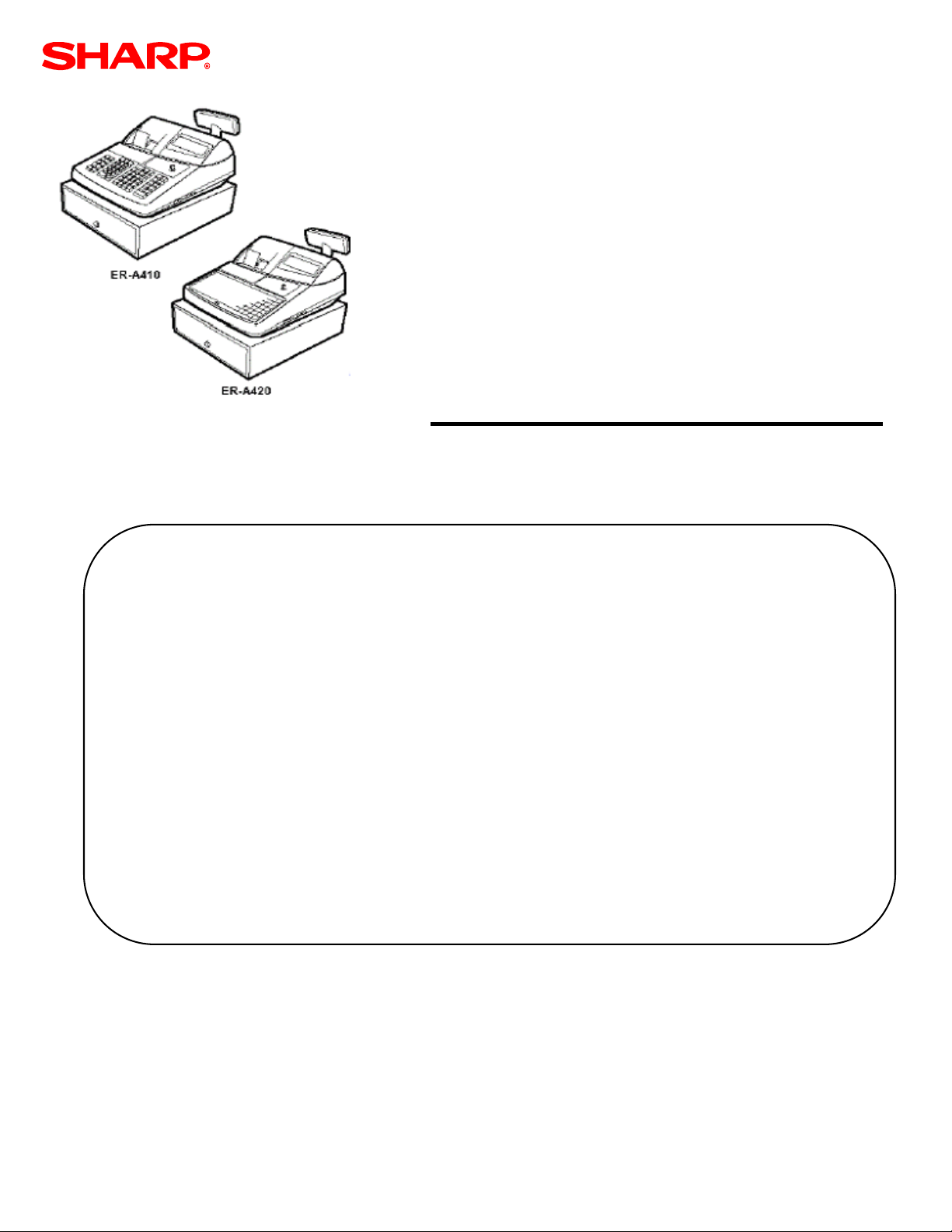
MODELER-A410/ER-A420
PC Link Setup Utility for
ROM Version RACC1A
Category Contents Pg
Section 1. Overview……………………………………………….……………….………
Section 2. Prior to Beginning ……..…………………………………….………..………
Cable Requirements…………………………………..………………………
Section 3. ER-A410/ER-A420 Setup …………………………...……………………….
Section 4. PC Hardware & Software Requirements …………………………………..
Section 5. PC Link Installation ……………………………………………….…………..
Section 6. PC Link Communications Settings ……………….…………………………
Section 7. Starting Initial Programming …………………………………………………
Section 8. Modifying Current Programming Data ……………………….……………..
Section 9. Downloading a Graphics Logo ……………………………….……………..
Section 10. Trouble Shooting & Error Messages ………………………………………..
Notice:
The PC Link software and/or documentation referred to in this manual are furnished under license by Sharp
Electronics Corporation and may only be used or copied in accordance with the terms of such license.
Except as permitted by such license, no part of the software or documentation may be reproduced, stored in a
retrieval system, or transmitted, in any form or by any means, electronic, mechanical, recording, or otherwise,
without the prior written permission of Sharp Electronics Corporation.
2
3
3
5
7
8
13
15
52
58
65
Designs and specifications are subject to change without notice.
Page 2

PC Link
TRADEMARKS
PC Link and Easy Programming Tool are trademarks of Sharp Corporation, Microsoft,
Windows, Windows 98SE, Windows 2000 and Win32 are trademarks of Microsoft
Corporation. All other trademarks and registered marks are the property of their respective
holders.
NOTICE TO USERS
This manual is intended to assist authorized Sharp dealers, with learning and
understanding how to install and provide support in the utilization of the PC Link software
utility for the ER-A410 and ER-A420 model cash registers. This assumes that you are
familiar with the general programming concepts of the ER-A410 and ER-A420. Please
read this introductory section carefully as it will provide helpful hints and recommendations
that will make your time more efficient and produce time saving results. This manual is not
intended for end user customers of authorized Sharp dealers.
Designs and specifications are subject to change without notice.
Page 1
Page 3
PC Link
Section-1: Overview
The Easy Programming Tool is a PC-based utility designed to assist you with the setup
tasks associated with the ERA410 and ERA420 model cash registers.
There are three basic functions provided by the PC Link utilities:
1 – Programming of preset data
2 – Graphic Logo image downloading
3 – All RAM Upload (storage) and Download (recovery)
Please refer to the chart below for the available programming options:
SRV-Mode Related Jobs: (X = indication of availability)
Job No. Description Yes No
900 System Presets X
950 Free Key – Function keys X
951 Free Key – Direct Keys (Dept. & PLU) X
975 Memory Allocation X
930-939 Z-Counters X
942-969 GT and Training GT X
944 PGM-2 Secret Code X
989 Memory Initial X
PGM 1/2-Mode Related Jobs: (X = indication of availability)
Job No. Description Yes No
11xx – 21xx Departments X
12xx – 22xx PLU/Sub departments X
13xx – 23xx Function keys X
15xx – 25xx Cashiers X
2119 Direct Key Assignment for Departments X
2219 Direct Key Assignment for PLU/Sub departments X
26xx Date/Time/Optional Settings X
2690 Peripheral Channel Assignment X
27xx Tax Rate/Tax Table Settings X
2900 Auto Key Programming X
61xx RS232 Options/Settings
71xx CAT (Credit Authorization Terminal) Setting X
989 Memory Initial X
Designs and specifications are subject to change without notice.
Page 2
Page 4
PC Link
Section-2: Prior to Beginning
Prior to using the PC Link setup utility, the following equipment is required:
- ER-A410/ER-A420
- Communications cable
- IBM compatible PC
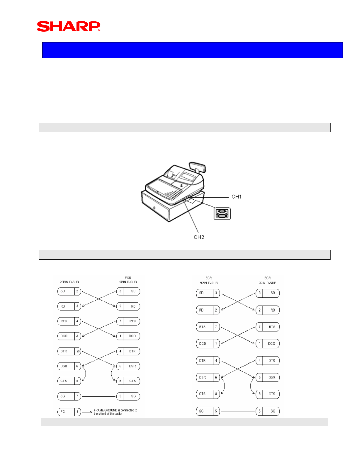
1. ER-A410/ER-A420 Communications Ports:
There are two communications ports standard as shown in the illustration below.
2. Cabling Connection Charts:
Example-1: The PC has a 25-pin D-Sub Example-2: PC has a 9-pin D-Sub
Designs and specifications are subject to change without notice.
Page 3
Page 5

PC Link
3. ECR Connection to the PC:
Once the connection cable is made, simply select either CH-1 or CH-2 at the ECR and then
connect the remaining end to the PC communications port to be used for the PC Link utility.
NOTE:
The PC Link utility uses the Online communications function and when connecting the
cable to the desired channel, no other device may be assigned to the same channel.
Designs and specifications are subject to change without notice.
Page 4
Page 6

PC Link
Section-3: ER-A410/ER-A420 Setup
It is recommended to establish the proper settings at the ECR prior to installing the PC Link
software at the PC.
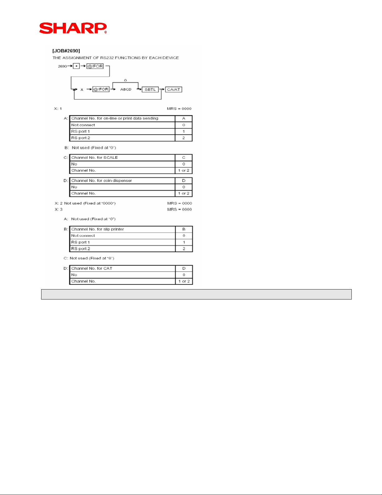
Step – 1: PGM Job#2690: Device Configuration
The ERA410/ERA420 RS232 Device Programming (2690 Option #1) must be set up to
communicate with PC Link. Select the channel to be connected to the PC and program the
Device Configuration Setting accordingly:
Example-1: Assigning the Online function to Channel-1
2690 Æ . Æ @/For Æ 1 @/For Æ1000 Æ SBTL Æ CA/AT: Channel No. 1
Example-2: Assigning the Online function to Channel-2
2690 Æ . Æ @/For Æ1 @/For Æ 2000 Æ SBTL Æ CA/AT: Channel No. 2
Designs and specifications are subject to change without notice.
Page 5
Page 7
PC Link
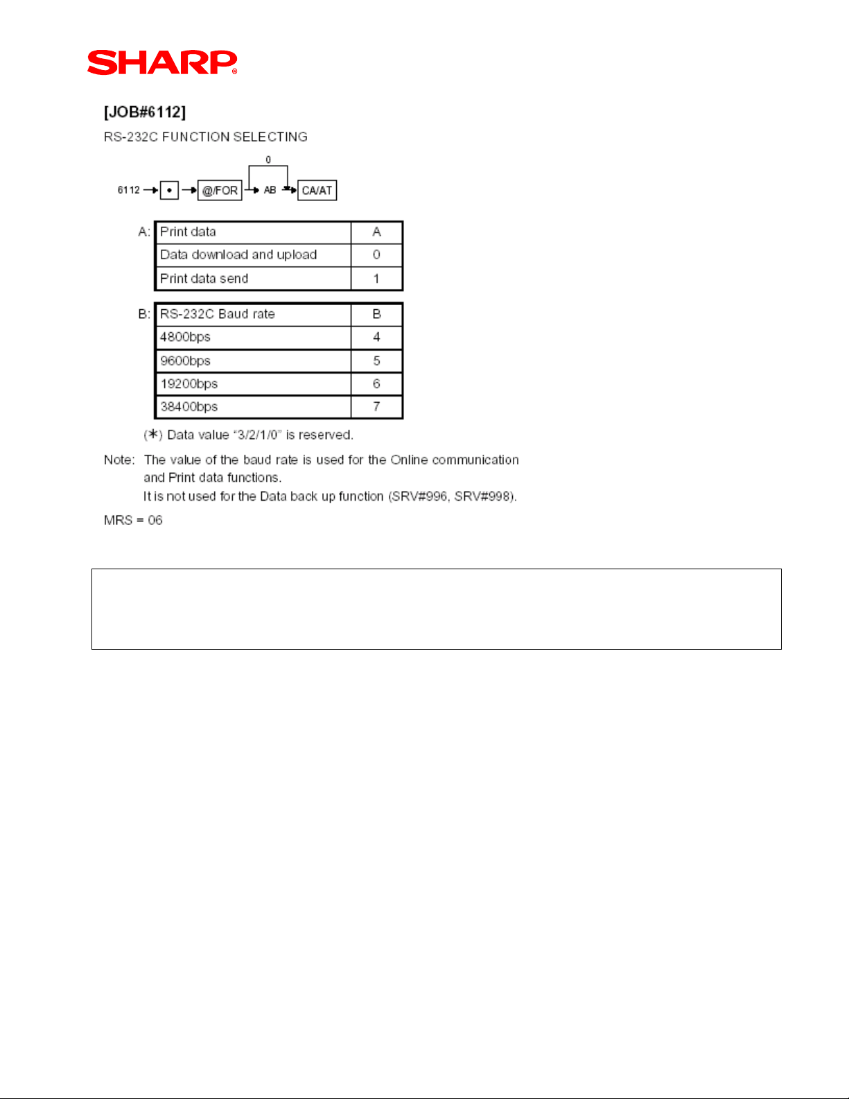
Step – 2: PGM Job#6112:
The communications baud rate must match the setting selected for the PC Link
communications utility.
Since the Online communications function is used for the PC Link utility “A” = “0”. Leading
zeros are not required, thus “B” is the setting variable for this programming job.
Designs and specifications are subject to change without notice.
Page 6
Page 8
PC Link
Example Settings:
AB = 04 : 4800 bps
= 05 : 9600 bps
= 06 : 19200 bps
= 07 : 38400 bps
Designs and specifications are subject to change without notice.
Page 7
Page 9

PC Link
Section-4: PC Hardware & Software Requirements
Once the PC Link utility has been installed, the minimum PC hardware and operating
systems required for operations are outlined below:
• IBM PC or 100% Compatible
o 24 MB DRAM for operations
o 40 MB Free Hard Disk Space
• Operating System
o Microsoft Windows 98/ME/2000/XP
• Display Setting
o 1024 x 768 – avoids scrolling when using the application
Designs and specifications are subject to change without notice.
Page 8
Page 10
PC Link
Section-5: PC Link Software Installation Procedures
The PC Link setup utility must be installed (versus copying) to facilitate communications
between the ECR and the PC.
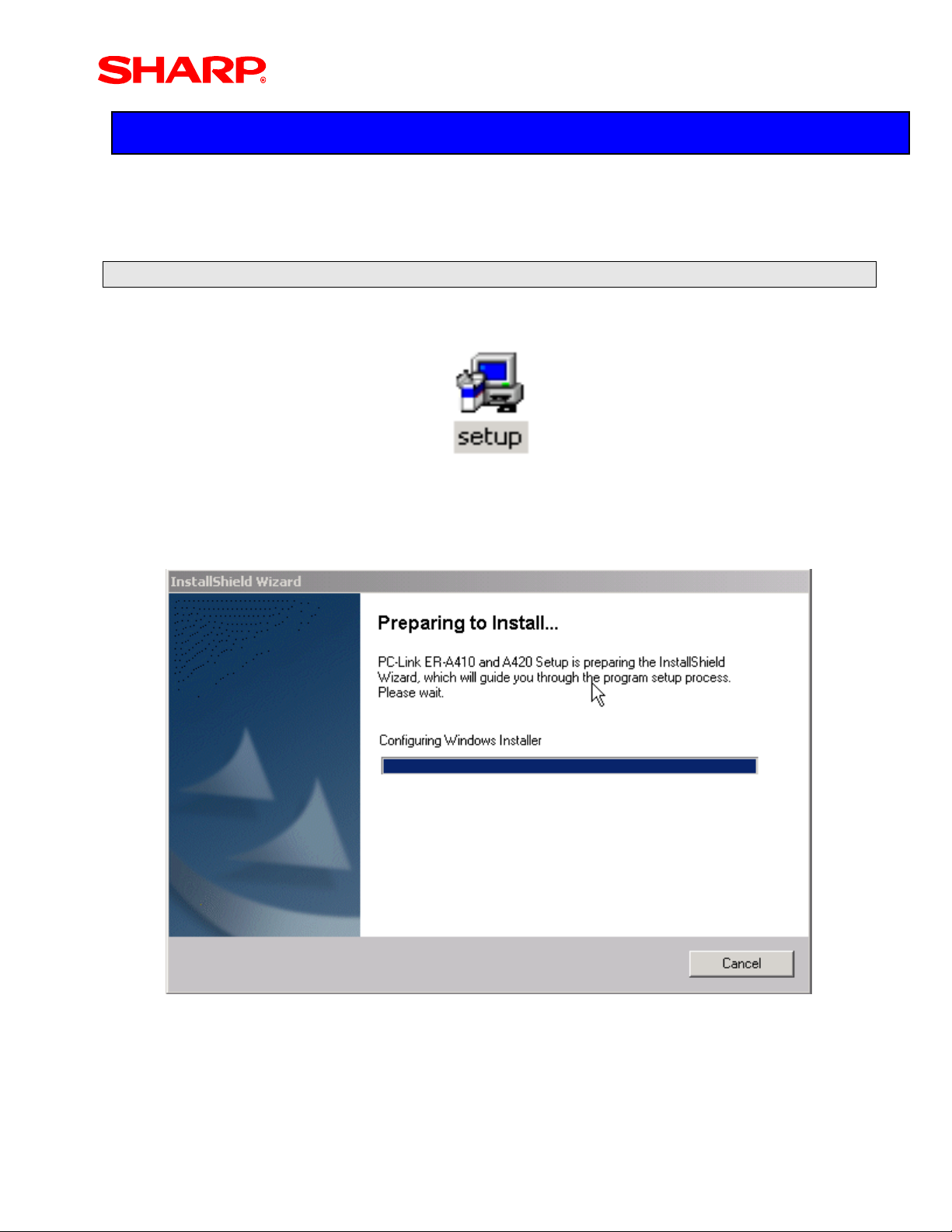
Step – 1: Start the Installation
1. Locate and Click on the Set Up Icon.
2. The following screens will be displayed during installation.
Designs and specifications are subject to change without notice.
Page 9
Page 11
K
PC Link
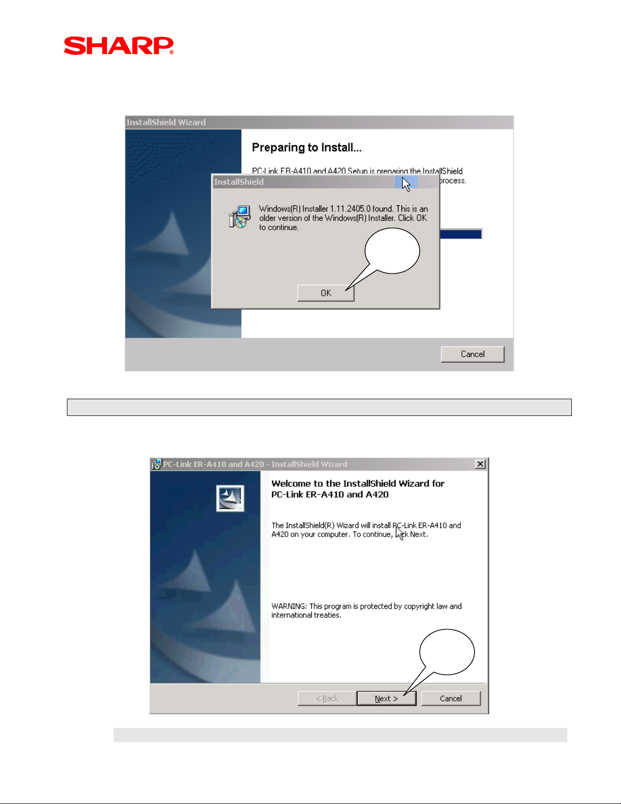
3. When an older version Windows® Installer is detected:
If an older version installer is detected – simply click [OK]
Click
O
Step – 2: Follow the InstallShield Wizard Prompts
When the InstallShield Wizard appears to begin installation – click [Next] to continue.
Click
Next
Designs and specifications are subject to change without notice.
Page 10
Page 12
g
PC Link
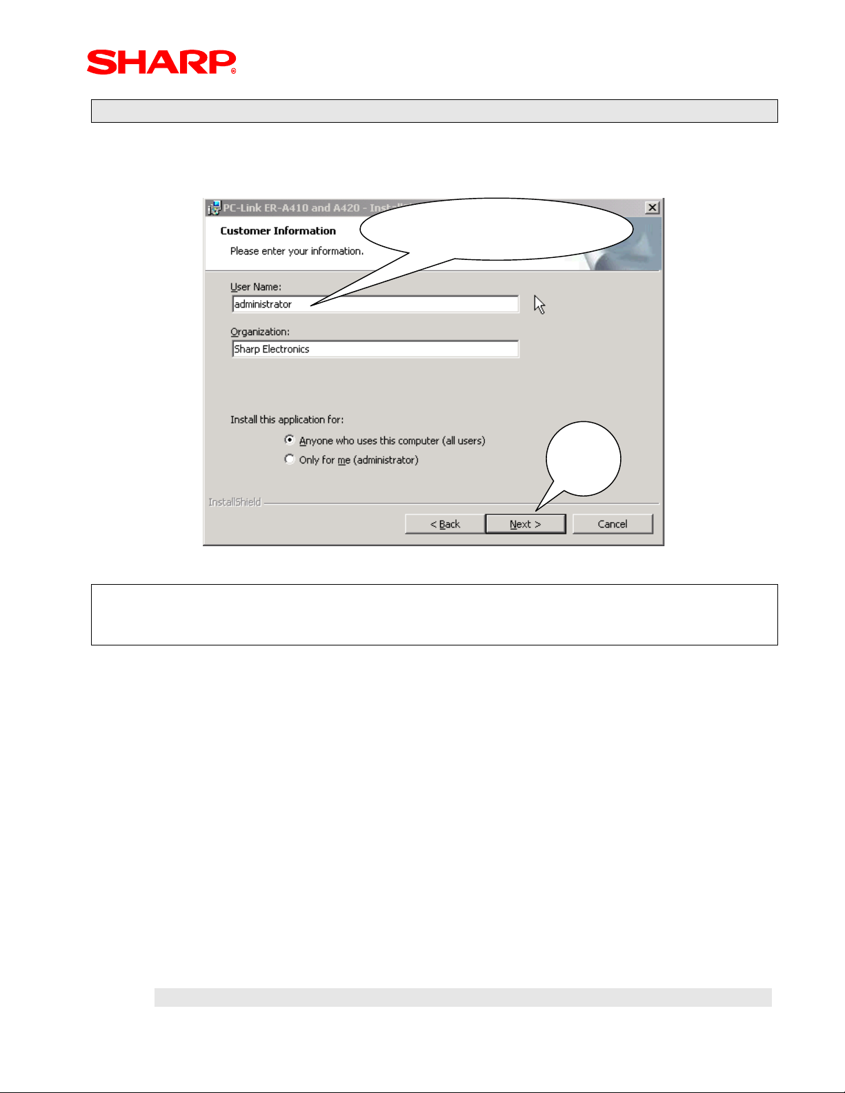
Step – 3: Enter the User Name & Organization
Provisions for entering a user name and organization are prompted. When finished you
click [Next] to continue.
Enter User Name &
Or
anization
Click
Next
NOTE:
When installing this utility, it is recommended to allow all users for the computer to have
access to the application.
Designs and specifications are subject to change without notice.
Page 11
Page 13

PC Link
Designs and specifications are subject to change without notice.
Page 12
Page 14
PC Link
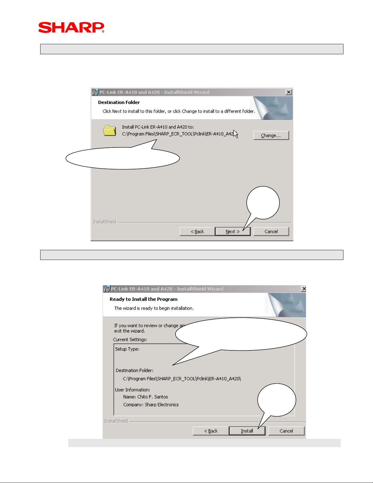
Step – 4: Select Destination Folder
For this installation example – it is recommended that the default folder be used for
installation. To accept the default settings – click [Next] to continue.
Accept Default Set Up
Click
Next
Step – 5: Review Information
Review the previously entered installation data. To accept the settings – click [Next].
Review Information
Entered
Click
Install
Designs and specifications are subject to change without notice.
Page 13
Page 15
PC Link
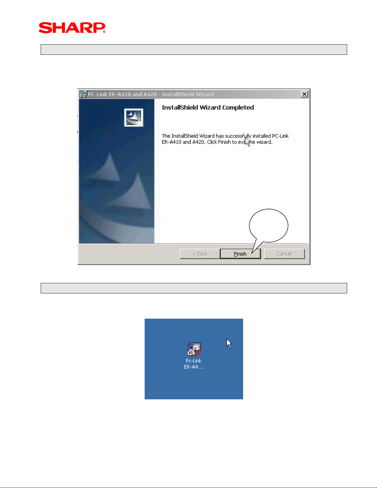
Step – 6: Complete the Installation Process
When the application has been successfully installed to complete and exit the InstallShield
Wizard – click [Finish].
Click
Finish
The PC Link icon will be on your computer desktop when the installation is done.
Step – 7: Locate the PC Link ICON
The PC Link icon will be located on your computer desktop when the installation is done.
Designs and specifications are subject to change without notice.
Page 14
Page 16
PC Link
Section-6: PC Link Communications Settings
Prior to launching the PC Link utility for programming, the communications settings at the
PC must be synchronized with the ECR.
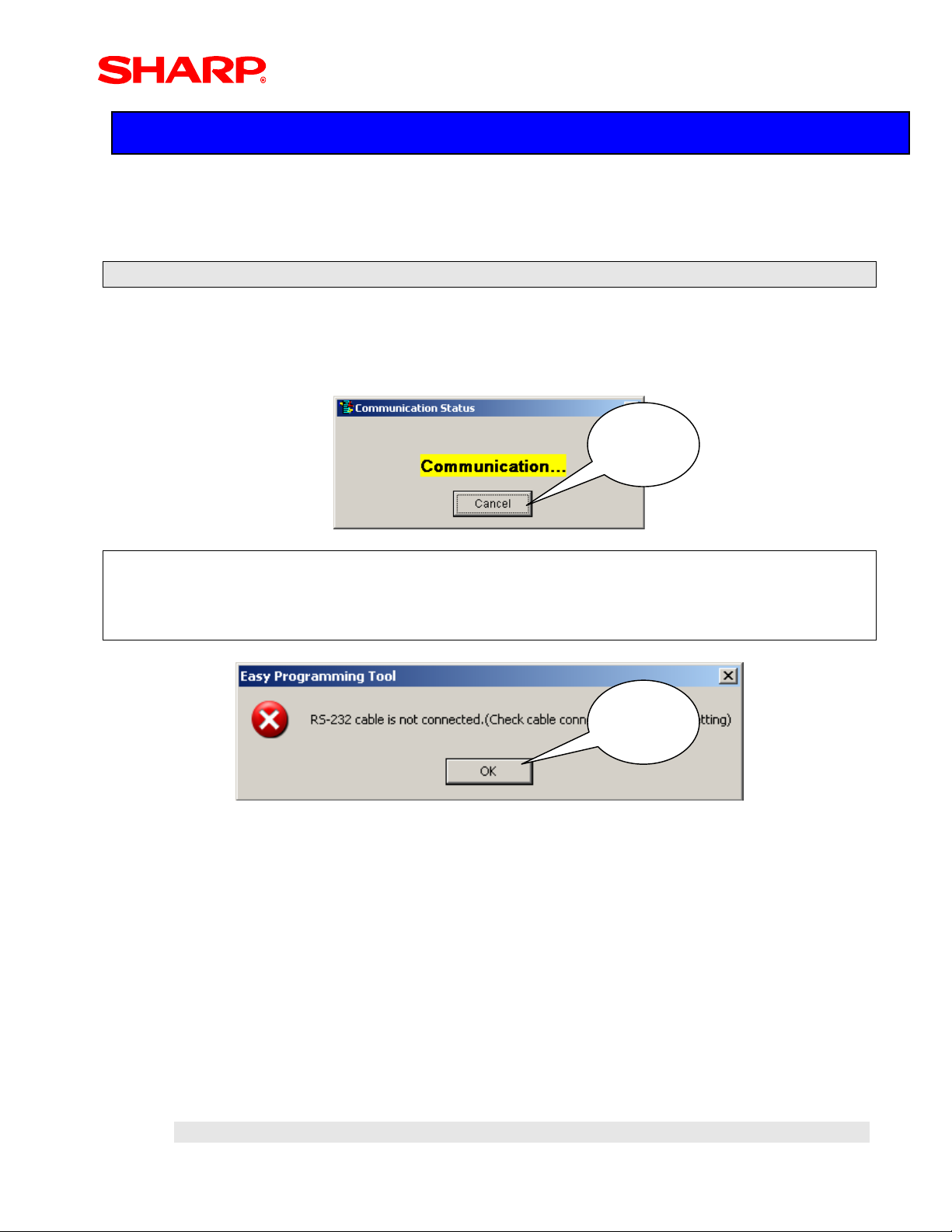
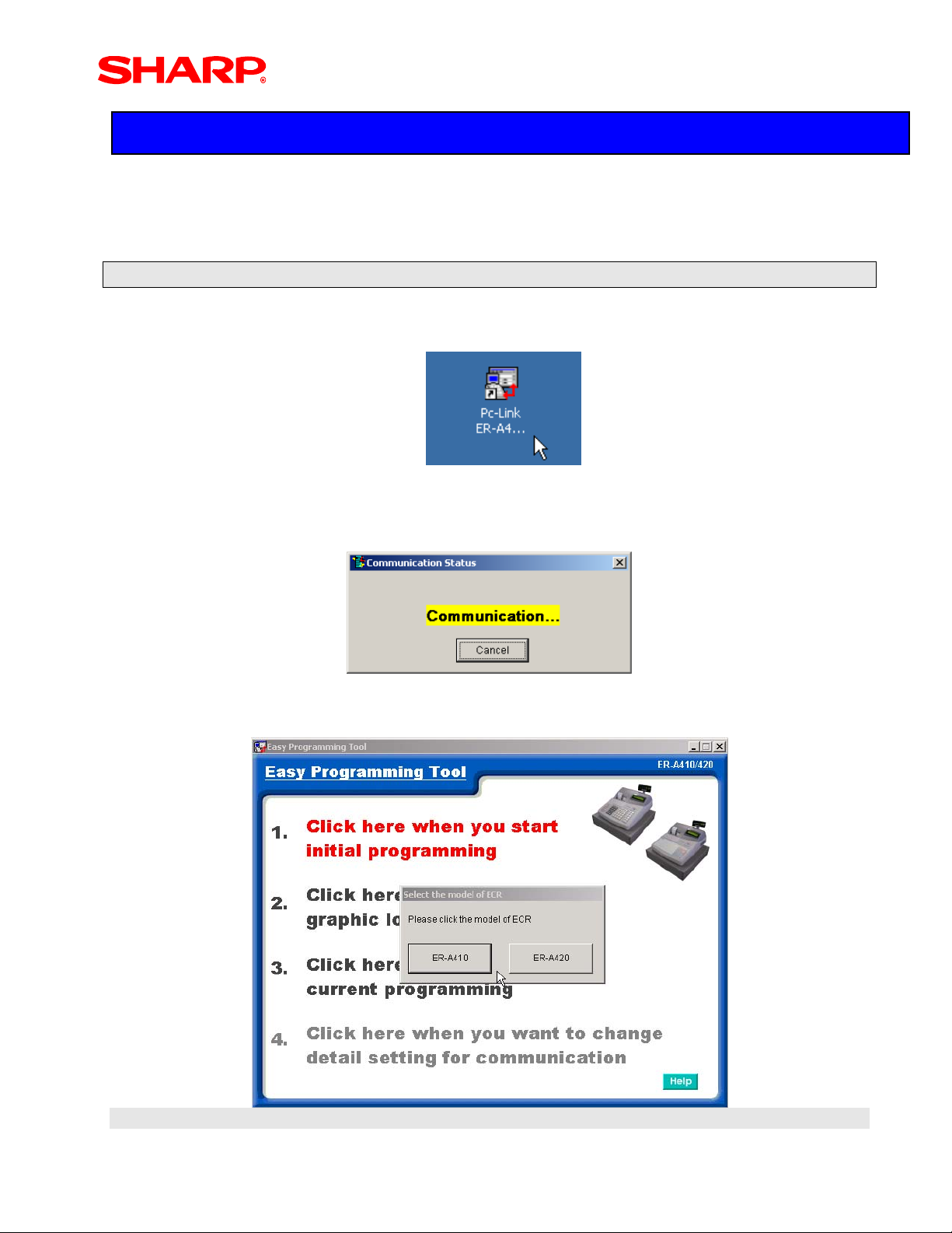
Step – 1: Launch the PC Link Utility
1. Launch the PC Link utility by double-clicking the PC Link ICON.
2. The PC Link utility automatically searches for a connected ECR – click [Cancel] to
bypass this step.
Click
Cancel
NOTE:
When the ECR is not connected and enough time lapses (the no. of retries is attempted
without a successful connection), the following error message will appear – to proceed with
setting the PC communications setup, click [OK]
Click
OK
Designs and specifications are subject to change without notice.
Page 15
Page 17
PC Link
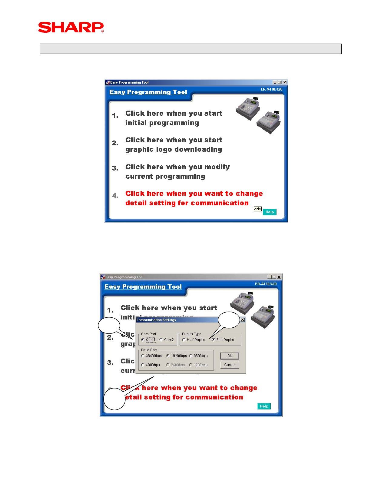
Step – 2: Select Communications Settings
1. Select Menu Option #4 to make the desired communications selections
2. Make the required communications settings as shown below.
a. Select the correct Com Port used at the PC (Not the ECR) – Com 1 or Com 2
b. Always use Full Duplex
c. Match the PGM Job code 6112 - Baud Rate Setting
b
a
c
3. Once the desired settings are selected – click [OK]
Designs and specifications are subject to change without notice.
Page 16
Page 18
PC Link
Section-7: Starting Initial Programming
Prior to launching the PC Link programming tool, insure that the ECR and the PC are
connected using the cable outlined previously.
Launch the PC Link Programming Tool
1. Launch the programming tool - double-click the PC Link Icon.
2. The PC Link application will search for the connection of the ECR through the
communications port – if everything is set correctly, the application will start.
3. Select Menu Option #1 - select the desired model ER-A410 or ER-A420 ECR.
Designs and specifications are subject to change without notice.
Page 17
Page 19
PC Link
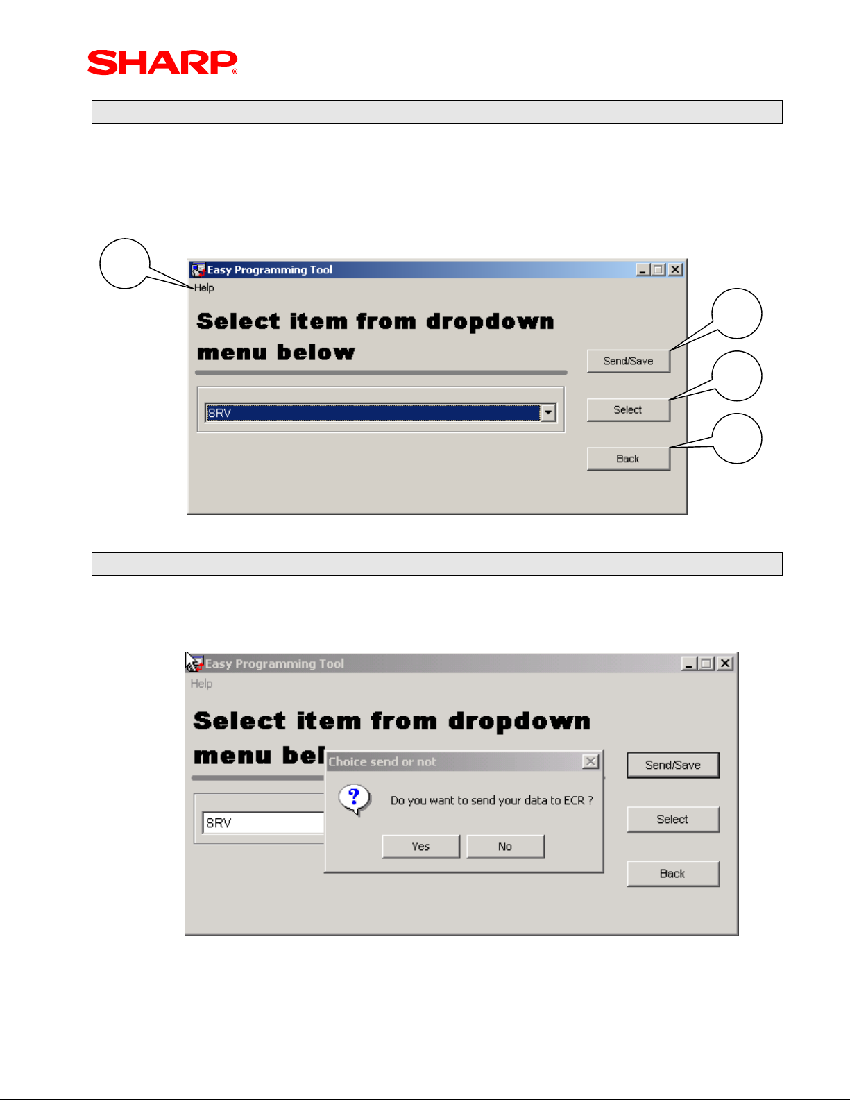
Initial Programming Main Menu
Overview of selections provided by the Initial Programming Main menu:
1. Help file: contains reference help for using the utility
2. [Send/Save] button: Dual function button which can save the data or send it
3. [Select] button: used to select the highlighted menu item
4. [Back] button: returns the application to the previous display
1
2
3
4
Sending/Saving Data
1. Selecting the [Send/Save] button – you will be prompted to send the changes to the
ECR.
2. To send data back to the ECR – click [Yes] or go to the next step to save on the PC.
Designs and specifications are subject to change without notice.
Page 18
Page 20
PC Link
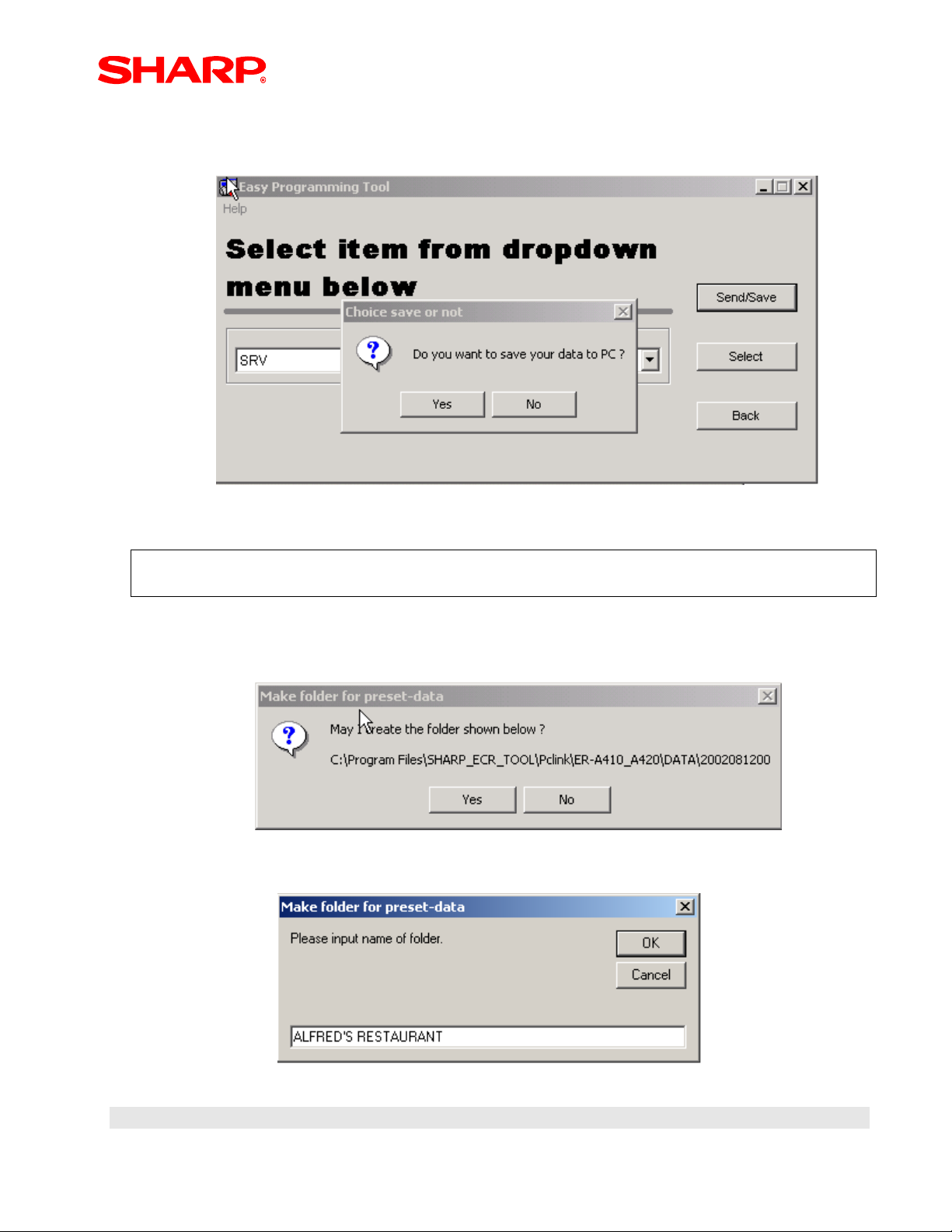
3. To save the data to the PC – click [No] and the prompt to save the data to the PC
will appear.
4. To save the data to the PC - click [Yes]
NOTE:
The PC Link utility will prompt to save the data to a designated date-stamped folder
5. To save the data to the designated dated folder – click [Yes] or click [No] to name
the folder
6. Name the folder – click [ok] when finished
Designs and specifications are subject to change without notice.
Page 19
Page 21
PC Link
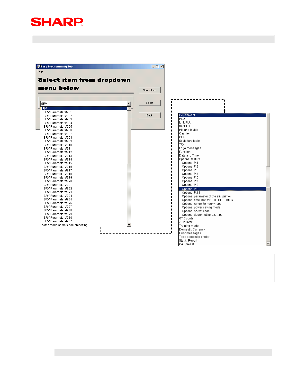
Menu Selections available from the Drop-Down Menu
Selections available from the Main Menu Drop-Down Menu option list:
NOTE:
The following examples for each available setting will relate to the above Main Menu and
refer to scrolling to the Menu selection. The above list also incorporates an alpha search
function to ease locating the desired Menu selection.
Designs and specifications are subject to change without notice.
Page 20
Page 22

PC Link
Example-1: Modifying a SRV Job
1. Highlight the desired “SRV Job” menu option from the drop-down list – double click
or highlight and click [Select].
Example: Selection for SRV Job#912
2. Edit the required selections within the SRV Job# - Click [Apply] when finished.
3. Continue with making additional changes or Click [Send/Save] – you will be
prompted to send the changes to the ECR:
a. To send data back to the ECR – click [Yes] or go to the next step to save on
the PC.
b. To save the data to the PC – click [No] and the prompt to save the data to the
PC will appear.
c. To save the data to the PC - click [Yes]
NOTE:
The PC Link utility will prompt to save the data to a designated date-stamped folder
d. To save the data to the designated folder – click [Yes]
Designs and specifications are subject to change without notice.
Page 21
Page 23
PC Link
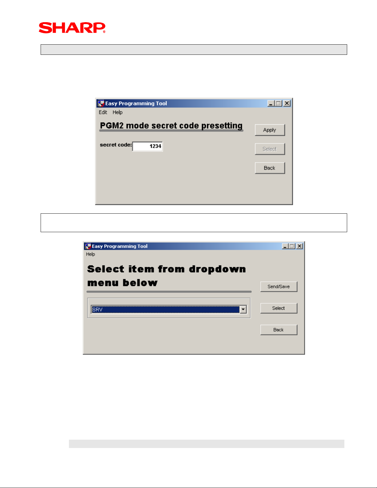
Example-2: Modifying the PGM2 Secret Code
1. Highlight the “PGM2 Secret Code” menu option from the Main menu – double click
or highlight and click [Select].
2. Enter the desired Secret Code – click [Apply]
NOTE:
When the [Apply] button is selected the program will return to the Main Menu.
Designs and specifications are subject to change without notice.
Page 22
Page 24

PC Link
Example - 3: Modifying a Department
1. From the Main Menu, scroll down and highlight the “Department” from the drop-
down list – double click or highlight and click [Select].
2. Select the desired Department from the provided listing – double click or highlight
and click [Select]
3. Edit the Department’s preset data - Click [Apply] when completed.
NOTE:
The program will return to the Departments List Menu when the [Apply] button is selected.
Designs and specifications are subject to change without notice.
Page 23
Page 25

PC Link
NOTE:
You can continue to program departments by using the Dept. code Drop-Down Menu.
4. Select a department from the Dept. code drop-down menu, you will be prompted to
save the previous changes made – Select [Yes].
Drop Down
Menu
5. When all modifications are completed - Click [Apply]
NOTE:
The program will return to the Departments List Menu when the [Apply] button is selected.
Designs and specifications are subject to change without notice.
Page 24
Page 26

PC Link
Example-4: Modifying PLU Items
1. From the Main Menu, scroll down and highlight the “PLU” from the drop-down list –
double click or highlight and click [Select].
2. Select the desired PLU from the provided listing – click [Select]
Designs and specifications are subject to change without notice.
Page 25
Page 27

PC Link
3. Edit the PLU’s preset data - Click [Apply] when completed.
NOTE:
The program will return to the PLU List Menu when the [Apply] button is selected.
Designs and specifications are subject to change without notice.
Page 26
Page 28

e shortcu
PC Link
4. When the number of PLU items is many, you can enter the PLU code – Select the
[RH arrow] to proceed.
Enter the PLU
code here for
th
t
NOTE:
You can continue to program PLU items by using the PLU code Select Menu.
Designs and specifications are subject to change without notice.
Page 27
Page 29

PC Link
5. When a PLU is selected using the PLU code select menu, you will be prompted to
save the previous changes made – Select [Yes].
PLU Code
Select Menu
6. When changes are completed – Click [Apply]
NOTE:
The program will return to the PLU List Menu when the [Apply] button is selected.
Designs and specifications are subject to change without notice.
Page 28
Page 30

PC Link
Example-5: Modifying Link PLU items
1. From the Main Menu, scroll and highlight “Link PLU” from the drop-down list –
double click or highlight and click [Select]
2. Select the Link PLU No., PLU Code, and enter the Linked PLU Code (Max. 5 PLU
items) – Click [Apply] when finished
NOTE:
The program will return to the Main Menu when the [Apply] button is selected.
Designs and specifications are subject to change without notice.
Page 29
Page 31

PC Link
Example-6: Modifying Set PLU Items
1. From the Main Menu, scroll down and highlight “Set PLU” from the drop-down list –
double click or highlight and click [Select]
2. Select the Set PLU No., PLU Code, and enter the Tied PLU Codes (Max. 10 PLU
items) – Click [Apply] when finished
NOTE:
The program will return to the Main Menu when the [Apply] button is selected.
Designs and specifications are subject to change without notice.
Page 30
Page 32

PC Link
Example-7: Modifying Mix & Match Items
1. From the Main Menu, scroll down and highlight “Mix & Match” from the drop-down
list – double click or highlight and click [Select]
2. Select the Table No., enter the Matching Count and Adjusted Dollar Amount – Click
[Apply] when finished
NOTE:
The program will return to the Main Menu when the [Apply] button is selected.
Designs and specifications are subject to change without notice.
Page 31
Page 33

PC Link
Example-8: Modifying Cashiers
1. From the Main Menu, scroll down and highlight “Cashier” from the drop-down list –
double click or highlight and click [Select]
2. Select the Cashier No., Edit the Cashier Code, Cashier Name (8 Char.) and Drawer
No. (1 – 2) – Click [Apply] when finished
NOTE:
The program will return to the Main Menu when the [Apply] button is selected.
Designs and specifications are subject to change without notice.
Page 32
Page 34

PC Link
Example-9: Modifying GLU Code Ranges
1. From the Main Menu, scroll down and highlight “GLU” from the drop-down list –
double click or highlight and click [Select]
2. Enter the Start GLU Code and End GLU Code – Click [Apply] when finished
NOTE:
The program will return to the Main Menu when the [Apply] button is selected.
Designs and specifications are subject to change without notice.
Page 33
Page 35

PC Link
Example-10: Modifying Scale Tare Table Settings
1. From the Main Menu, scroll down and highlight “Scale tare table” from the drop-
down list – double click or highlight and click [Select]
2. Enter the Tare weight for each Tare table – Click [Apply] when finished
NOTE:
The program will return to the Main Menu when the [Apply] button is selected.
Designs and specifications are subject to change without notice.
Page 34
Page 36

PC Link
Example-11: Modifying Tax Settings
1. From the Main Menu, scroll down and highlight “TAX” from the drop-down list –
double click or highlight and click [Select]
2. Enter the Tax No., Tax Rate, Calc type, Cycle Amount and input the Tax Table –
Click [Apply] when finished
NOTE:
The program will return to the Main Menu when the [Apply] button is selected.
Designs and specifications are subject to change without notice.
Page 35
Page 37

PC Link
Example-12: Modifying Logo Messages (Text Type)
1. From the Main Menu, scroll down and highlight “Logo Messages” from the drop-
down list – double click or highlight and click [Select]
2. Edit each Line of Logo Text based on the SRV Job#912-D Setting – Click [Apply]
when finished
NOTE:
The program will return to the Main Menu when the [Apply] button is selected.
Designs and specifications are subject to change without notice.
Page 36
Page 38

PC Link
Example-13: Modifying Function Settings
1. From the Main Menu, scroll down and highlight “Function” from the drop-down list –
double click or highlight and click [Select]
2. Edit each Function’s Text Setting (Max. 8 Char.) – Click [Apply] when finished
NOTE:
The program will return to the Main Menu when the [Apply] button is selected.
Designs and specifications are subject to change without notice.
Page 37
Page 39

PC Link
Example-14: Modifying Date & Time Settings
1. From the Main Menu, scroll down and highlight “Date and Time” from the drop-down
list – double click or highlight and click [Select]
2. Edit the Calendar Date and Time – Click [Apply] when finished
NOTE:
The program will return to the Main Menu when the [Apply] button is selected.
Designs and specifications are subject to change without notice.
Page 38
Page 40

PC Link
Example-15: Modifying Optional Feature Settings
1. From the Main Menu, scroll down and highlight “Optional P: 1 ~ Optional P: 13” from
the drop-down list – double click or highlight and click [Select]
2. Edit each bit using the Drop-Down Menu within the optional feature selection – Click
[Apply] when finished
NOTE:
The program will return to the Main Menu when the [Apply] button is selected.
Designs and specifications are subject to change without notice.
Page 39
Page 41

PC Link
Example-16: Modifying the Slip Printer Parameters
1. From the Main Menu, scroll down and highlight “Optional parameter of the slip
printer” from the drop-down list – double click or highlight and click [Select]
2. Edit AB: Initial Line Feed each print, CD: Max. Line Print per side, E: No. of enforced
Validation prints when compulsory and F: Feed lines after the [Tray SBTL] key is
depressed – Click [Apply] when finished
NOTE:
The program will return to the Main Menu when the [Apply] button is selected.
Designs and specifications are subject to change without notice.
Page 40
Page 42

PC Link
Example-17: Modifying the Till Timer Settings
1. From the Main Menu, scroll down and highlight “Optional time limit for THE TILL
TIMER” from the drop-down list – double click or highlight and click [Select]
2. Edit the time limit (0 – 255) in seconds, which is used to increment the Drawer Count
Qty totalizer – Click [Apply] when finished
NOTE:
The program will return to the Main Menu when the [Apply] button is selected.
Designs and specifications are subject to change without notice.
Page 41
Page 43

PC Link
Example-18: Modifying the Hourly Range Optional Settings
1. From the Main Menu, scroll down and highlight “Optional range for hourly report”
from the drop-down list – double click or highlight and click [Select]
2. Edit A: Time Range format and BC: Start Time used for the Hourly Report (00 – 24)
– Click [Apply] when finished
NOTE:
The program will return to the Main Menu when the [Apply] button is selected.
Designs and specifications are subject to change without notice.
Page 42
Page 44

PC Link
Example-19: Modifying the Power Saving Mode Settings
1. From the Main Menu, scroll down and highlight “Power saving mode” from the drop-
down list – double click or highlight and click [Select]
2. Edit A: Time Range format and BC: Start Time used for the Hourly Report (00 – 24)
– Click [Apply] when finished
NOTE:
The program will return to the Main Menu when the [Apply] button is selected.
Designs and specifications are subject to change without notice.
Page 43
Page 45

PC Link
Example-20: Modifying the Optional Secret Code Settings
1. From the Main Menu, scroll down and highlight “Optional Secret Code” from the
drop-down list – double click or highlight and click [Select]
2. Edit the Secret Codes (0 – 9999) for each selection – Click [Apply] when finished
NOTE:
The program will return to the Main Menu when the [Apply] button is selected.
Designs and specifications are subject to change without notice.
Page 44
Page 46

PC Link
Example-21: Modifying the GT (Grand Total) Settings
1. From the Main Menu, scroll down and highlight “GT” from the drop-down list –
double click or highlight and click [Select]
2. Edit the desired GTs, Training GT, Balance GT as necessary – Click [Apply] when
finished
NOTE:
The program will return to the Main Menu when the [Apply] button is selected.
Designs and specifications are subject to change without notice.
Page 45
Page 47
PC Link
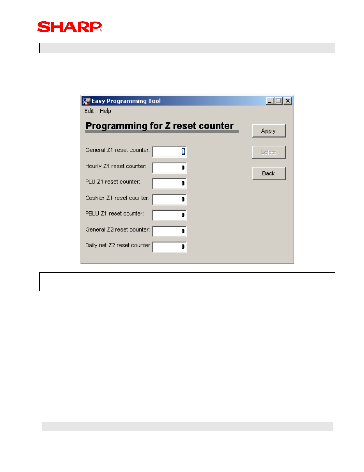
Example-22: Modifying the Z Counter Settings
1. From the Main Menu, scroll down and highlight “Z counter” from the drop-down list –
double click or highlight and click [Select]
2. Edit the desired Z counter (1 – 9999) as necessary – Click [Apply] when finished
NOTE:
The program will return to the Main Menu when the [Apply] button is selected.
Designs and specifications are subject to change without notice.
Page 46
Page 48

PC Link
Example-23: Modifying the Training Cashier Settings
1. From the Main Menu, scroll down and highlight “Training Mode” from the drop-down
list – double click or highlight and click [Select]
2. Select the Training Cashier Code and Edit the desired Receipt Title Text as required
– Click [Apply] when finished
NOTE:
The program will return to the Main Menu when the [Apply] button is selected.
Designs and specifications are subject to change without notice.
Page 47
Page 49
PC Link
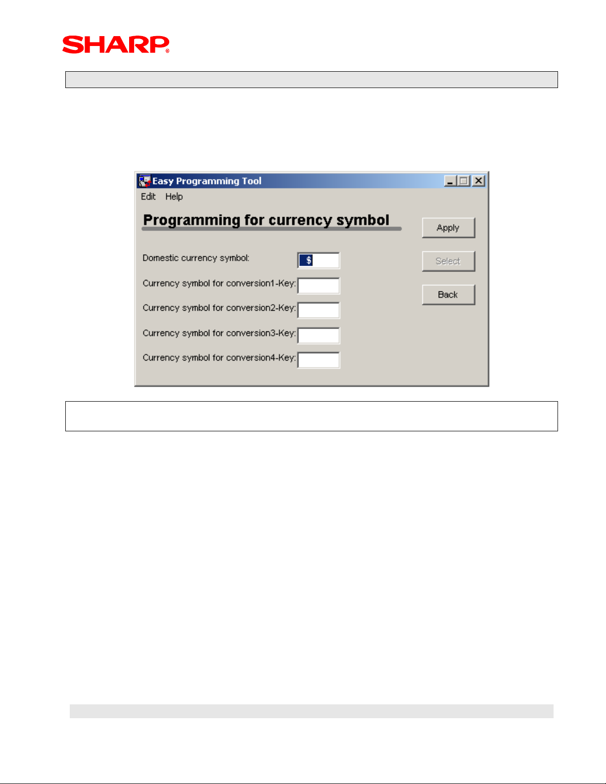
Example-24: Modifying the Domestic Currency Symbol Settings
1. From the Main Menu, scroll down and highlight “Domestic Currency” from the drop-
down list – double click or highlight and click [Select]
2. Edit the Domestic Currency and Currency Conversion (1-4) Symbol as required –
Click [Apply] when finished
NOTE:
The program will return to the Main Menu when the [Apply] button is selected.
Designs and specifications are subject to change without notice.
Page 48
Page 50

PC Link
Example-25: Modifying the Error Messages Settings
1. From the Main Menu, scroll down and highlight “Error Message” from the drop-down
list – double click or highlight and click [Select]
2. Select the Error Text No. and edit the Error Message Text – Click [Apply] when
finished
NOTE:
The program will return to the Main Menu when the [Apply] button is selected.
Designs and specifications are subject to change without notice.
Page 49
Page 51
PC Link
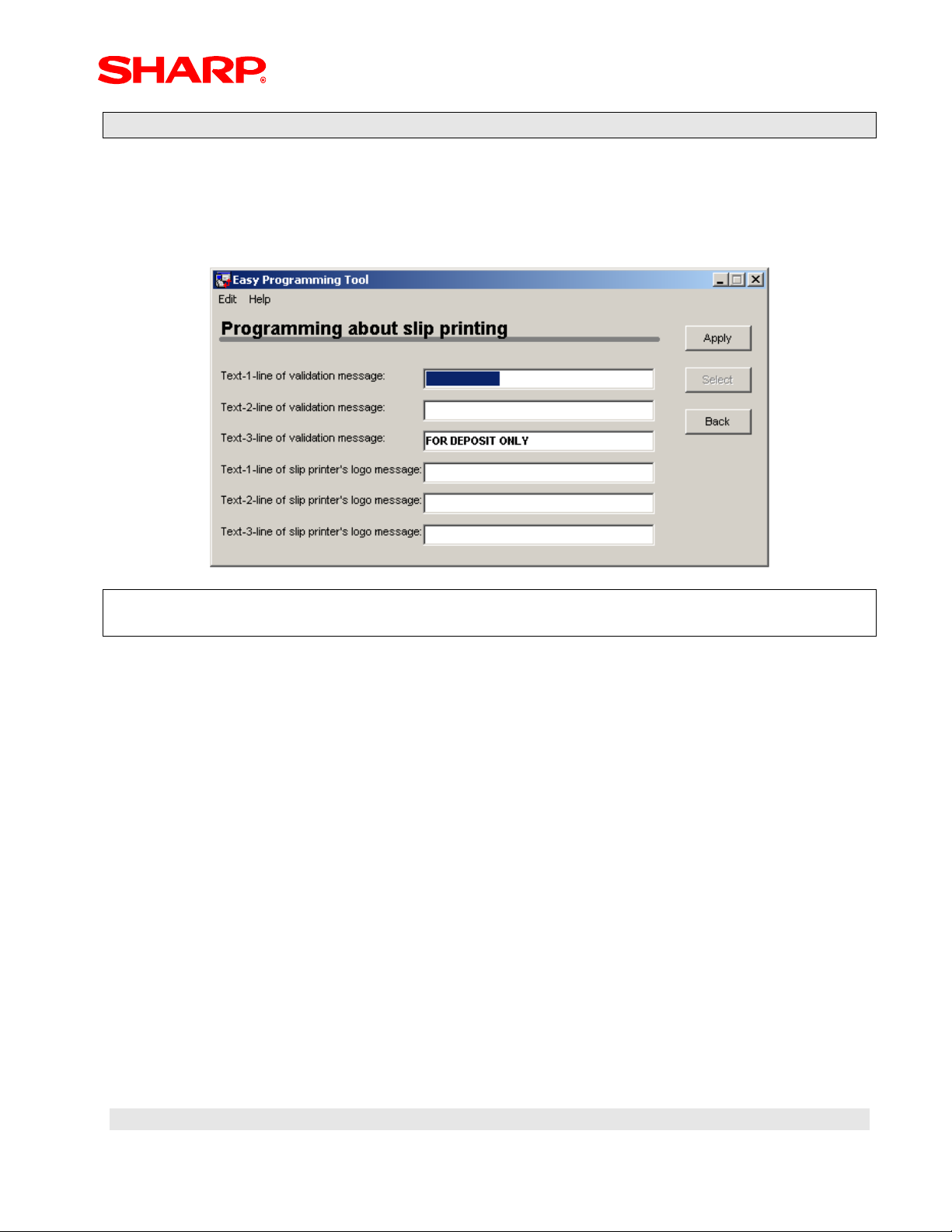
Example-26: Modifying the Slip Printer Messages
1. From the Main Menu, scroll down and highlight “Texts about slip printer” from the
drop-down list – double click or highlight and click [Select]
2. Select the Text Line used for Validation and Text Line used for the Slip printer Logo
and Edit the Text as required – Click [Apply] when finished
NOTE:
The program will return to the Main Menu when the [Apply] button is selected.
Designs and specifications are subject to change without notice.
Page 50
Page 52

PC Link
Example-27: Modifying the Stacked Report Settings
1. From the Main Menu, scroll down and highlight “Stack Report” from the drop-down
list – double click or highlight and click [Select]
2. From the Edit Menu, select “Add Stack” – when prompted to Add stack data – Click
[OK] to proceed.
3. The PC Link utility will assign a “Sequence No.” automatically, then edit the report
type from the Job No. drop-down list and enter a start/end range parameter (when
applicable).
4. Repeat Steps-2 & 3 for each stack report to be added – Click [Apply] when finished.
Designs and specifications are subject to change without notice.
Page 51
Page 53

PC Link
NOTE:
The program will return to the Stack Report Menu when the [Apply] button is selected.
5. When all settings are completed – Click [Back] when finished.
NOTE:
The program will return to the Main Menu when the [Back] button is selected.
Designs and specifications are subject to change without notice.
Page 52
Page 54

PC Link
Example-28: Modifying the CAT Settings
1. From the Main Menu, scroll down and highlight “CAT” from the drop-down list –
double click or highlight and click [Select]
2. To complete the settings for the CAT interface, please refer to the ER-A410 and
ER-A420 Dealer Knowledge Book for the Data Cap Interface – Click [Back] to return
to the Main Menu
Designs and specifications are subject to change without notice.
Page 53
Page 55

PC Link
Section-8: Modify Existing Program Data from the ECR
Prior to launching the PC Link programming tool, insure that the ECR and the PC are
connected using the cable outlined previously.
Launch the PC Link Programming Tool
1. Launch the programming tool - double-click the PC Link Icon.
2. The PC Link application will search for the connection of the ECR through the
communications port – if everything is set correctly, the application will start.
3. Select Menu Option #3 – and the Current Programming Main menu will appear..
Designs and specifications are subject to change without notice.
Page 54
Page 56

PC Link
Modifying Current Programming Main Menu
Overview of selections provided by the Modify Current Programming Main menu:
1. Item Select Options: select by “individual”, “All” or “clear All” previous selections
2. [From ECR] button: initiates communications to collect data from the ECR based on
the selected programming data.
3. [From Your PC] button: initiates a browser search for the folder
4. [Cancel] button: returns the application to the previous display
1
2
3
Designs and specifications are subject to change without notice.
Page 55
4
Page 57

PC Link
When Selecting the Source Data from the ECR
1. When the [ECR] button is selected – Communications is initiated to the ECR
2. The data uploaded from the ECR is based on the data selected
3. The PC Link Main Menu appears – all settings are the same as outlined in the Initial
Programming Sections
NOTE:
Only those data selected previously will be displayed in the Main Menu drop-down list.
Designs and specifications are subject to change without notice.
Page 56
Page 58

PC Link
When Selecting the Source Data from the PC
1. When the [PC] button is selected – a browser in launched to locate the data folder.
2. Highlight the desired folder – Click [OK]
3. The PC Link Main Menu appears – only those settings selected are loaded and
available for modifications.
Example: Only Departments and PLU were selected from the program data list
4. Highlight the desired program data to be modified – Click [Select]
Designs and specifications are subject to change without notice.
Page 57
Page 59

PC Link
Sending/Saving Data
When the modifications to the current program data are completed you may send the data
directly to the ECR or save them within a folder on the PC.
1. Selecting the [Send/Save] button – you will be prompted to send the changes to the
ECR.
2. To send data back to the ECR – click [Yes] or go to the next step to save on the PC.
3. To save the data to the PC – click [No] and the prompt to save the data to the PC
will appear.
4. To save the data to the PC - click [Yes]
Designs and specifications are subject to change without notice.
Page 58
Page 60

PC Link
NOTE:
The PC Link utility will prompt to save the data to a designated date-stamped folder
5. To save the data to the designated dated folder – click [Yes] or click [No] to name
the folder
6. Name the folder – click [ok] when finished
Designs and specifications are subject to change without notice.
Page 59
Page 61

PC Link
Section-9: Downloading a Graphics Logo
Prior to downloading a Graphics Logo to the ER-A410 or ER-A420, you must insure that
the ECR Logo settings match.
Step-1: Preparing the ECR for Graphic Logo usage
1. SRV-Mode Programming options – SRV Job#912-D
2. Make one of the following settings:
a. Select 1 for Graphic LOGO Only
b. Select 2 for Graphic LOGO and 3 Line Footer
c. Select 4 for Graphic LOGO and 3 Line Header
Designs and specifications are subject to change without notice.
Page 60
Page 62

PC Link
3. PGM2 Mode Programming Options
4. Make one of the following settings:
a. Bit-H = 0 for No Logo on the Receipt footer
b. Bit-H = 1 for a Logo to be printed on the Receipt footer
Designs and specifications are subject to change without notice.
Page 61
Page 63

PC Link
Step-2: Downloading a Graphic Logo usage
Prior to launching the PC Link programming tool for downloading a graphic logo, insure that
the proper Logo Image is available on the PC as outlined below.
Logo Image Attributes must conform to the below specifications:
• File – BMP Format
• Size – 288 dots (w) x 130 dots (h)
• Color – Black & White Only
Black Rate:
Total Black Rate: 35% or Lower
Local Black Rate: The black rate of a horizontal dot line is 55% or less.
Designs and specifications are subject to change without notice.
Page 62
Page 64

PC Link
Launch the PC Link Programming Tool
Prior to launching the PC Link programming tool, insure that the ECR and the PC are
connected using the cable outlined previously.
1. Launch the programming tool - double-click the PC Link Icon.
2. The PC Link application will search for the connection of the ECR through the
communications port – if everything is set correctly, the application will start.
3. Select Menu Option #2 – and the Graphic Logo utility will initialize
Designs and specifications are subject to change without notice.
Page 63
Page 65

PC Link
4. Assuming that you have a bitmap image ready for download – Click [Continue]
5. Using the browser, locate the desired logo graphic to be downloaded – double click
or highlight and click [Open]
6. If the selected image conforms to the 288x130 attributes then the image will be
displayed – if not an error will result
Designs and specifications are subject to change without notice.
Page 64
Page 66

PC Link
Example of an accepted logo image
7. If the Logo Image is acceptable – Click [Send]
8. Send the logo to a destination in the ECR – Click [Yes] for the header and [No] for
the footer.
9. The PC Link will initiate communications to download the image.
Designs and specifications are subject to change without notice.
Page 65
Page 67

PC Link
Note:
The PC will return to the EASY PROGRAMMING TOOL Main menu when finish.
Designs and specifications are subject to change without notice.
Page 66
Page 68

PC Link
Section-10: Trouble Shooting & Error Messages
Occasionally there will be errors experienced when using the PC Link application utility.
Standard Errors
1. When the cable is improperly connected
2. When the cable not connected.
3. When PGM2 Mode 2690 RS232 Device Programming is not set up correctly or the
baud rate setting does not match.
4. When entry is outside of a designated range – Example is entering “25” in a field that
has the range of 00 – 24.
.
Designs and specifications are subject to change without notice.
Page 67
Page 69

PC Link
5. Example of an error when using a logo image that doesn’t conform
Non-Standard Errors
1. When an inappropriate Function key is selected during entry.
Note:
To clear the error – Click [OK], the application will close and in order to proceed you will
have to re-launch the PC Link utility from the desktop Icon.
Designs and specifications are subject to change without notice.
Page 68
Page 70

COPYRIGHT© 2002 BY SHARP ELECTRONICS CORPORATION
All rights reserved.
Printed in the U.S.A.
No part of this publication may be reproduced,
stored in a retrieval system, or transmitted.
In any form or by any means,
electronic, mechanical, photocopying, recording, or otherwise,
without prior written permission of the publisher.
Designs and specifications are subject to change without notice.
 Loading...