

Page 1
CODE: OOZER31001M.M
—
—
Page 2

ENGLISH .....................
DEUTSCH. .....................Seite 59
.Page 1
FRAN~AIS. ....................Page
ESPANOL, .....,...............Pagina181
119
Page 3
CONTENTS
Page
GENERAL
1.
SUMMARY OF THE ER-3100 OPTIONS
2.
BEFORE INSTALLINGOPTIONS
3.
PRINTING OUT THE SRV-MODE AND PGM-MODE PROGWS .............
4.
REMOVING THE TOP CABINET AND MAIN DRAWER
5.
Removing the top cabinet
5.1
Replacing the top cabinet
5.2
Removing the main drawer
5.3
Replacing the main drawer .................................
5.4
Rs-232c INTERFACE (ER-31RS2)
6.
6.1
Outline
6.2
Installationprocedure .....................................
*0*9**9***0*90***0******0*.*.........................
● *.***....********,****,*...**
...............
● .*****.● **..*..● *.*
.........**.......**
.......
● .*..*.*..................● *.*.*.*
...............
● .**.*.*● *.**.***● ....*.**..*.*.**....***.**.****,**
● ..***.*.*.*..**.*..*.*.● ..*
● *.**..*● .*.*.......
● **..*............*****.*..****.
1
2
4
6
10
10
11
11
12
.
14
14
15
6.3
Operationalcheck
6.4
Programming
7.
RAM MEMORY CHIP (ER-46PLI)
7.1
Outline
7.2
Installationprocedure .....................................
7.3
Operationalcheck
7.4
Programming
● *.***...*...*.● ..*....● .**.*..● *..*...● ...*....
● ****.*.● ***O.***● .9..*.................**.m● *.**.**
.......
.**.***
● **.*.*● *.**..*● .**...*..**...*● .******...
● .......● . . . . . . . . . . . . . . . . . . . . . . . . . . . . . . . .
● *****..● .**.*.*● .**.*..● ..*.*..● .*
.*..*.*
● ..*..*....***...***.**....
-i-
20
21
35
35
35
36
38
Page 4

8.
PRESETS LOADER
8.1
Outline *..*..*..*..*...*....*..***.**.**....m.*.*****0***.*
8.2
Installationprocedure
8.3
Operationalcheck
.**.**......*e*e**e******a**********a**e*a*.e*
● .*.*.......*.*.***m*.*me**.*me*.e***
.*.*.....******e*****m***me***e.**be***.**
Yage
42
42
42
44
8.4
8.5
8*6
9.
9.1
9.2
9.3
9.4
10.
10.1
10.2
10.3
Programming ................................................
Data sending and receiving .................................
Use of the ER-OIFD 3.5-inch floppy disk unit
REMOTE DMWER (ER-37DW3)
Outline
● ...*............● .....*...**.*..*....*.****● *******
Installationprocedure
Operationalcheck
● ***.***● ..*..,.*● **.....*● .*.****.● ******
.***..*
● *.*....● ..*..***.**.**.**● *.**.***● *
● ..*..*.● .**..*.● .**..*.● .*..
8****.**.*..*..
Modificationof the PGM-mode program .......................
MODE SWITCH (ER-31ml/~2/~3/~4/~5) ....OOO..eoeo=.oco....
Outline
Installationprocedure
Operationalcheck
.....**...........................*.*.......*.*.....
...............
● ....*.............*..*........● ....***● *.
● ......*...**.*...*..*
45
46
47
49
49
49
52
53
54
54
54
57
- ii -
Page 5
1. GENERAL
Table 1 shows all options availablefor the ER-3100 cash
1.
register.
Some options require removing the top cabinet or modifying the
2.
SRV-modeand PGM-mode programs.
Therefore,
OPTIONS” on page 4 before installingany option.
be sure to consult Section3 “BEFORE INSTALLING
–l–
Page 6

2. SUMMARYOF THE ER-31OOOPTIONS
Table 1
Name
LS-232C
Lnterface
M memory
:hip of the PLU capability.
tiodeswitch
lemote
~rawer
?resets
Loader
ER-31RS2 This option is the RS-232C
ER-46PL1
ER-31MD1
ER-31MD2
ER-31MD3
ER-31MD4
ER-31MD5
ER-37DW3
ER-OIFD
ER-52CB
Model name
interfacethat provides data
transferbetween the ER-31OOS
or between the ER-31OO and a
personal computer or kitchen
printer.
This option enables the expansiom
This option is available in
100 varieties.
A single remote drawer can be
connectedto the ER-31OO.
3.5-inch floppy disk unit
S10 interfacecable
Remarks
ER-67LC
;oin case ER-38CC
;oin case
:over
3attery
In addition to the above options, those shown in Table 2 on the next
page are optionallyavailable through the Parts Department.
ER-38cvl/cv2/cv3/cv4/cv5
ER-30BT
Level converter
–2–
Page 7

Table2
Name
Journal near-end sensor
Validationsensor
Drawer open sensor*
I
Water-proofpush-buttoncashier switch cover
Mode switch key grip cover (for the operator key)
Service key for the optionalmode switch (ER-31MD)
Service key for the standardmode switch
Drip-proof printer cover
Real key one-hole type clerk switch (four kinds)
* The standard cash drawers of the machines for some destinationsare
equippedwith no drawer open sensor.
Part code
DKIT-8226RCZZ
DKIT-8227RCZZ
DKIT-8331RCZZ
GCOVB6872RCZZ
LKGIM7126RCZZ
LKGIM7094RCZZ
LKGIM7113RCZZ
DKIT-8322Rczz
DKIT-8321RCZZ
\.
–3–
Page 8

3. BEFORE ~STALLING OPTIONS
If you install any option in the ER-31OO register already in use,
you must have a Z reading
the installation.
If the register is not reset, sales data stored in the register
may be destroyed.
Print out the SRV-mode and PGM-mode programs before installing
2.
any option.
installation.
For the printout procedure refer to Section 4 “PRINTING OUT THE
SRV-MODEAND PGM-MODE PROGRAMS” on page 6.
If you install optional expansionRAMs and/or ROM (for the
3.
ER-31RS2) in the ER-31OO registeralready in use, perform data
saving for memory protectionby using the S10 interface in
advance. After the option(s)has been installed,perform data
loading for restoringmemory contents.
LOADER” for the data saving/loadingprocedure. It is advisable
to perform the above data saving when installingother options.
As a safety measure, be sure to turn the mode switch to the OFF
4.
It may be necessary to modify each program after
performedby its user before
See Section 8 “PRESETS
performing
position and unplug
If you do not unplug the register, the transformerPm will
remain on.
The ER-31OO is equippedwith various SRV-mode functions to aid
5.
you in installing the options.
than those shown in each of the followingsections, so that data
stored is not destroyed.
To install any options other than the remote drawer and presets
6.
loader, you need to remove the top cabinet. Please read 5.1
“Removing the top cabinet”under Section 5 “REMOVING ~E TOP
CABINET AND MAIN DRAWER~ on page 10.
drawer or ER-31RS2 interfacecable,
drawer. Please read 5.3 “Removingthe main drawer” on page 11.
the registerbefore installingany
Never enter any job numbers other
To install the remote
you need to remove the main
–4–
option.
Page 9

Model
name
ER-46PLl
Removal of the
top cabinet
needed
Table3
S10 interface
needed
Modificationof
the SRV-mode and
PGM2-modeprograms
needed
*
Service key
needed
ER-31RS2
ER-31MD1
ER-31MD2
ER-31MD3
ER-31MD4
ER-31MD5
ER-37DW3
ER-52CB
ER-67LC
&
ER-OIFD
ER-38CC
ER-38CV1
IER-38cv2I
ER-38CV3
ER-38CV4
ER-38CV5
needed
needed
not needed
not needed
not needed
I
not needed
not needed
not needed
needed
needed
not needed
needed
not needed
needed
needed
needed
needed
(supplied)
needed
not needed
needed
not needed
I I I
not needed
not needed
needed
needed
(for ER-31MD)
needed
—
needed
needed
needed
Hot needed
not needed
–5–
Page 10

4.
P~~G OUT THE SRV-MODE AND PGM-MODEPROGWS
The
1.
(1) Programmodification (SRV or PGM mode)
SRV-modeand PGM-mode programmingof the ER-31OO relies on
job numbering system.
the
PGM-mode programs,follow the proceduresbelow.
For a printout of the SRV-mode and
Job number
(2) Program printout (SRV or PGM mode)
Job number~
2.
It is necessary to print out the current SRV-modeand PGM-mode
programsusing the followingproceduresbefore installingany
option.
(1) Printing out the SRV-mode program
Put the service key in the mode switch and turn it to the SRV
position.
@ Full item printout of the SRV-modeprogram -- job number 900
9oo~ x ~
Refer to sample printout 1, page 8.
@ Printoutof key position codes -- job number 950
950~
Refer to sample printout 2, page 8.
(2) Printing out the PGM-mode program
Turn the mode switch to the PGM position.
—-m-m~
m—--m
E
m—-m
m
Data~TL
D
@ Printout of function information-- job number 1
1~
m~m
Refer to sample printout 3, page 8.
@ Printout of departmentalinformation-- job number 10
~~~
10
Refer to sample printout 4, page 9.
m
–6–
Page 11

@ Printout of PLU information-- job number 20
Start PLU
code
Refer to sample printout 5, page 9.
@ Printout of set PLU information--
23~
Refer to sample printout 6, page 9.
@ printout of cashier numbers --
40—~~
Refer to sample printout 7, page 9.
m—-m
m
End PLU
code
job n~mber A()
job ~um~er 23
–7–
Page 12
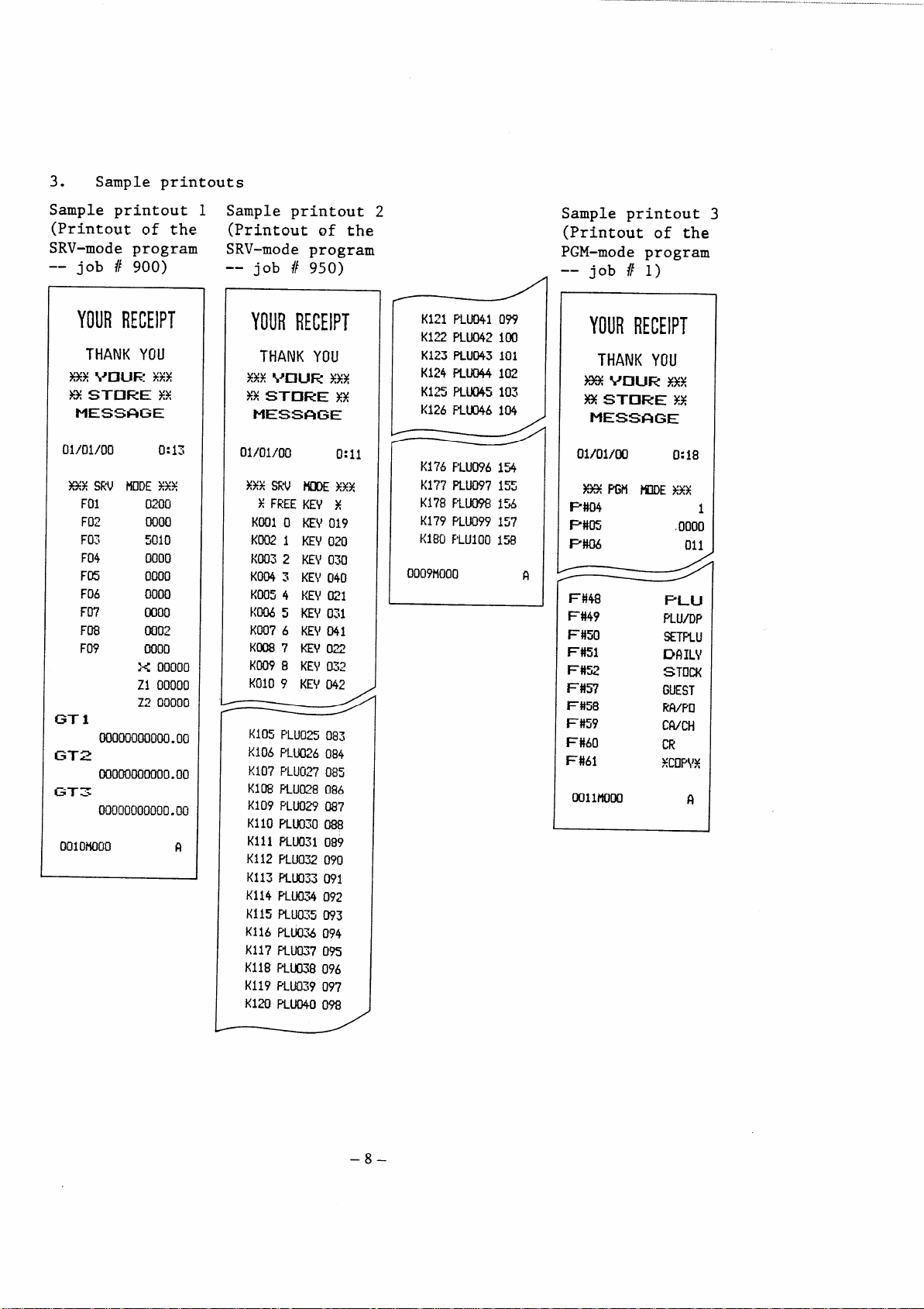
3. Sample printouts
Sample printout 1
(Printoutof the
SRV-modeprogram
-- job # 900)
YOURRECEIPT
01)01/00
HXSRV ~DE Y++
F(I1
Ftt2
Fo~
F04 0000
FE
F06 0000
F07
F08
F09
GT1
Ooooooooooo.oo
GT2
Ooooooooooo.oo
G-T3
00000000000.00
Oolomoo
0:13
a~fj~
0050
5010
Oooo
0000
~o~
0000
:< 00000
ZI 00000
Z2 00000
R
Sample printout 2
(printoutof the
SRV-modeprogram
-- job # 950)
YOURRECEIPT
01/01/00
K105F’LU025083
RI06F’L~96 o84
K107F’LLJ027085
K108RU028 086
KI09 PLU029087
Kl10F’LU02d088
KillF’LU031of39
K112 F’LU032090
K113 Ru033 WI
K114PLU’i 09z
mua~s093
K115
K116RU074094
K1l?F’Lu037
Kii8R1.K138096
K119PLU039097
K120F’LuD400?8
0:11
09S
K121PLU04i099
KlZPLU042im
K123FLU043101
Ki24fiU044102
K125RU045103
KI26F’LUD46104
K176F’LU09613
K177PLU097155
K17SF’LU0981%
K179FLU099157
K180
F’LU1OOIW
Ooo?tlooo
Sample printout 3
(Printoutof the
PGM-mode program
-- job # 1)
YOURRECEIPT
ol/ol/cnl
I P#04
P#m
I
I F’#06
9
F#48
F#49
F#50
F#51
F#W
1=#57
F#58
F#59
F#60
F#61
Oollmoo
0:18
1
.0000
011
–8–
Page 13

Sample printout 4
(Printoutof the
PGM-mode program
-- job # 10)
Sample printout 5
(Printoutof the
PGM-mode program
-- job # 20)
Sample printout 6 Sample printout 7
(Printoutof the
PGM-mode program
-- job # 23)
(Printoutof the
PGM-mode program
--job #40)
YOURRECEIPT
01/01/00
Y33PGN
Iml
mlPLu
Z#Gl
WLU
Mnl
mTPLu
4#al
Oo4PLu
5#Ql
WJPLU
$#01
O06PLU
7#Ql
O07PLU
8#ul
O08PLU
WI
098PLu
99#1
099PLu
lmcll
100PLU 0.00
oo18m
0:24
WE%%X
SET
-0.01
SET
-0.m
SET
-0.03
SET
-0.04
SET
-o.m
0.06
0.07
0.08
0.00
0.00
$
YOURRECEIPT
SET
-0.01
mu 10
PLu11
PLu12
PLU 13
PLu 14
SET
-0.02
PLu 8
F’LU 9
PLU 10
SET
-0.03
SET
-0.04
SET
-0.05
SET
0.00
F’LU92
PLU 9S
PLu 94
fi
YOURRECEIPT
01/01/00
0:26
–9–
Page 14

5. REMOVING THE TOP CABINET AND MAIN DRAWER
5.1 Removing the top cabinet (Fig. 1)
1. Turn the mode switch to the OFF position and unplug the cash
register.
Fix the front of the key sheet to the top cabinet by attaching
tape to two locations.
2. Raise the customer display by pulling it in the direction of the
arrow A.
Remove the two screws situated on the right and left sides of the
3.
top cabinet.
back of the cabinet.
4. Remove the top cabinet by moving it in the directions of the
arrows B, C, and D in this sequence,
Then remove the printer cover and the screw at the
(Fig. 1)
h
‘/
Fix
n
‘\
A
..
\
–lo–
Page 15

5.2 Replacing the top cabinet
Replace the top cabinet in the reverse order of removing,
When replacing the cabinet,
use care to prevent the heat sink
from catching the cables that connect the display PWB and main
Pm.
Also, prior to fixing the top cabinet make sure the interface
cable between the display PWB and the main PWB is securely
connected to the socket on the main PWB.
5.3 Removing the main drawer
1. Remove the two screws from the bottom of the drawer.
(Fig. 2)
Fig. 2
2.
Move the main unit forward (in the direction of the arrow a) and
lift upwards (the arrow b).
3.
Disconnect the drawer connectioncable and grounding strap.
(Fig. 3)
–11–
Page 16

Fig. 3
5.4 Replacing the main drawer
1. Reconnect the drawer connectioncable and grounding strap.
2.
Fit the pawls on the bottom of the main unit into the holes in
the drawer by moving the main unit in the directionof the arrow
c and move it backward (in the direction of the arrow d).
(Fig. 4)
Fig. 4
– 12–
Page 17

Secure the drawer to the main unit by using the two screws
3.
removed in step 1 of 5.3.
(Fig. 5)
I
Fig. 5
–13–
Page 18

6. RS-232C INTERFACE (ER-31RS2)
6.1
Outline
0
EIA (ElectronicsIndustriesAssociation)standard RS-232C is
associatedwith the transfer of binary serial data, control
signals, and timing signalsbetween
0
The RS-232C interfaceis one of the
the exchange of informationbetween
modems and data terminals.
devices generally used for
a computer and a peripheral
device.
0
This interface (ER-31RS2)was designed to conform to the EIA
standard,but in particularit was designed for connection
between the ER-31OO and a data processingmachine.
0
It becomes necessary to set communicationspecificationsof the
ER-31RS2 (e.g. baud rate) matched to those of the data processing
machine, when the ER-31RS2 is connectedwith a data processing
machine that is equippedwith the RS-232C2 interface.
0
The jumper-switch (Jl
- J8) on the ER-31Rs interface circuit
board must be used to choose the specifications.
0
Refer to “RS-232C Specificationbook” publishedby Engineering
Department,
ElectronicsIndustriesAssociation (EIA), for details
of RS-232C requirements.
Com~onents
The ER-31Rs2 consistsof the followingcomponents.
1) Interfaceboard unit (CPWBE6951RC06)
2) Control ROM (VH127256R223A)
Note: The version of the control ROM is indicatedby the last
characterof its part code.
(This control ROM is version A.)
3) Connectingcable (QCNW-7059RCZZ)
4) Others
A) Ferrite core (RCORF6629RCZZ)
2 pcs.
B) Connector spacer for mini pitch (PSPAB2343RCZZ)2 pcs.
Connector spacer for inch pitch (PSPAB2333RCZZ) 2 pcs.
C) Screw (XUPSD30P08000)
(XBPSD30P06KSO)
–14–
2 pcs.
2 pcs.
Page 19

D) Nut (XNESD26-20000)
2 pcs.
E) Spring washer (XWSPN26-06000)
F) Grounding cable (QCNW-6791RCZZ)
Note: If the machine is equippedwith grounding cable, it is
not necessary to connect this cable (Fig. 9).
The cable and connector to be connected to the external
equipmentneed to be procured locally.
For the connector to be attached to the ER-31RS2 connecting
cable, use either of the followingthat can be mounted on the
bottom cabinet of the ER-31OO.
0 Mini pitch DB-C6-J1O-1 (JAEmake) (SHARPpart code:
LCHSM6656RCZZ)
“ Inch pitch DB-C6-JIO-2 (JAE make) (SHARP part code:
LCHSM6657RCZZ)
Use a shielded cable for connectingcable.
6.2
Installationprocedure
Prior to installingthe ER-31RS2 perform data saving for memory
protection
by using the S10 interface. For the data
2 pcs.
1 pc.
saving
procedure,
Remove the
1.
see Section 8 “PRESETSLOADER”.
top cabinet and main drawer.
(Refer to Section 5 “
REMOVING THE TOP CABINET AND MAIN DRAWER”.)
2.
Installationof the control ROM.
Remove the RAM PWB unit from the main PWB and connect the control
ROM to the ROM3 socket on the main PWB.
(Note that the control
ROM is placed in the same directionas the ROM1 and ROM2.)
After the control ROM has been installed,replace the RAM PWB
unit.
–15–
Page 20

Servicebattery
RSTs
\
~RAM PWBunit
M
Notes: 1. The connectorsof the RAM PWB unit are both taped so
that it can resist vibrationsduring transportation.
Remove the tapes from the connectorsprior to the
installationwork and attach tapes again to the
connectorsafter completionof the installationwork.
2. Prior to removing the RAM PWB unit connect the
service
service
the RST
unit is
battery
entirelydestroyed.
battery (CKOG-6626RCZZ)to this unit and the
connector (UKOGGO056CSZZ)to the ON side of
switch for memory protection.
If the RAM PWB
removedwithout connectingthe service
and service connector,the RA.Mdata is
If this is the case, take master
resetting 1 when starting the ER-31OO.
The RAM data may be destroyed even when the above
action is taken for memory protection.
If the
ER-31OO cannot start normally after installingthe
control ROM, start it by master resetting 1.
It is advisable to perform data saving by using the
–16–
Page 21

S10 interface.
This enables RAMs to be loaded with
saved data after master resetting 1 even if their
contents are destroyed.
Master resetting 1:
Memory all clear start (masterreset start)
For master resetting 1, plug in the register,
holding down the journal feed key in the SRV mode.
3. If master reset (MRSI or MRS2) is performed at the
ER-31OO equippedwith the R22113ROM as a common ROM
after the ER-31RS2ROM has been installedin it, it
is automatica~lyloaded with SSP data to activate the
ER-31RS2 program. At this time every SSP data
already programmed is cleared.
Accordingly,it is
necessary to program the programmed SSP data again
after master reset has been performed.
If the ER-31OO is equippedwith any version other
than the R221B comon ROM, it
loaded with the SSP data; and
is not cleared. The SSP data
loaded into the ER-31OO is as
is not automatically
the programmed SSP data
that is automatically
follows:
SSP No.: ER31OO-OO1
1. 01
2. 01
3. 134
4. 244
5. 00
6. 134
7.
246
8. 00
9. 06
10. 24
11. 131
12. 01
13. 00
14. 24
15. 189
16. 183
17. 84
18.
122
–17–
Page 22

Mount the RS-232C interfaceboard unit on the bottom cabinet.
3.
Pass the two cables of the unit through the ferrite core, wind
them on the core by one turn, and connect them to the main unit.
(Fig. 7)
tecore
6629RCZZ
Fig. 7
Break off the knockout for cable hole @ on the right side of
the bottom cabinet.
4.
Remove the option mounting bracket from the rear of the bottom
cabinet and break off the knockout for cable hole @ by means of
a wire cutter or the like.
(Fig. 16 on page 49)
(Fig. 8)
v
Optionmounting
LANGK7228RCZZ
bracket,
I
Fig, 8
–18–
Page 23

Secure the 25-pin connectorof the ER-31Rs2 connectingcable to
5.
the option mounting bracket removed in step 4 above togetherwith
the groundingwire of the cable.
(Note that pin 1 faces this
side.)
When fixing the 25-pin connector,
use either of the supplied two
types of connector spacers (inch pitch type silver spacer and
mini pitch type golden spacer).
Select the one that matches the
mating connector.
@
/’-----~EsD26-2oooo
ble
Fig. 9
6.
Restore the option mounting bracket to the bottom cabinet.
7.
Connect the connectorat the other end of the connectingcable to
part @ shown in Fig. 7.
8.
Connect the mating connector to the connector secured to the
option mounting bracket from below the bottom cabinet and then ~€
fix the mating connector.
–19–
Page 24

Replace the top cabinet and drawer.
9.
(Refer to Section 5
“REMOVINGTHE TOP CABINET AND MAIN DRAWER”.) At this time draw
out the drawer cable from the bottom cabinet at the back or
through cable hole @ on its right side (see Fig. 16 on page
49).
Use care to prevent the drawer cable, groundingwire, etc.
from being caught between the bottom cabinet and the drawer.
6.3 Operationalcheck
0 Preparation
Connect the test connector to the 25-pin RS-232C connector (25P
D-sub) of the ER-31Rs2.
QCNW-7059RCZZ
MainPWB
ER-31RS2
Interface
PWB
CPWBF6951RC06
$ 0
Testconnector
UKOG-6639RCZZ
/
After connectingthe test connector (UKOG-6639RCZZ)to the 25P
D-sub, interfacePWB input and output signalsmust be connected
in followingmanner.
ER
I
,
DR
0 Start of the test
The test will start after the followingkeyboard command in the
SRV mode.
119~
Note:
n
The above command would not be acceptedunless the
ER-31RS2 control ROM (27256)is in the ROM socket (ROM3)
on the main PWB of the ER-31OO.
cause the “Check over”
print and automaticallyfinalize
The above operationwill
the check program.
–20–
Page 25

IT
‘3
119
\
Data entry with
numeric keys
I
A~B+c+D~
/
I
Sample“Checkover”print
If any print other than shown above occurs, it indicates that the
ER-31RS2 is malfunctioning.
6.4 Programming
1. Modificationof the SRV-modeprogram
0 Reprogrammingto enable or disable the ER-31Rs2 option to select
the kitchn printer or the RS-232C communicationfunction.
.—.l~.—>
909 ~ —~
In the above key operation,
data of job number 909; and for convenience,data in the fourth
column is called A, the one in the third column B,
second column C, and the one in the first column D.
Of these data, data D decideswhether to enable or disable the
ER-31RS2 option and to select the kitchen printer or the RS-232C
communicationfunction.
Kitchen printer/
RS-232C communication function
RS-232C communication function
Kitchen printer
Note:
For data D, never enter any digit other than those shown
A, B, C, and D each refer to preset
the one in the
Change the data according to Table 4.
Table 4
ER-31RS2
option
Disable
Enable
Disable
Enable
Data
o
1
2
3
in the above table.
–21–
Page 26

Data A, B, and C do not need to be changed.
same data as data A, B, and C of job number 909 shown in
Enter the
the SRV-mode program list printed
installingthe option.
2. PGM-modeprogramming
(1) Programmingto select data handling
The ER-31Rs2 has the followingfour
which can be enabled or disabledby
programming.
0 Sending of print data
0 Sending of report print data
0 Loading of RAM data
0 Dumping of RAM data
a. Programmingprocedure
Perform this programmingin the PGM
followingprocedure.
When A, B, C, and
D are all zeroes
by job number 900 before
functions
data handling functions,
the PGM-mode
mode by using the
zgo~~~~
A Sending of print data Enable/Disable
B Sending of report print data Enable/Disable
c Loading of RAM data Enable/Disable
D Dumping of RAM data Enable/Disable
‘~AB~D $ ,~
A, B, C, and D are all set to zeroes
when master resetting is taken.
Table 5
–22–
1/0
1/0
1/0
1/0
Page 27

b. Print
The contents of the programmingare printed on the
receipt/journalpaper. The print format is shown below.
The logo and date printed are the same as those printed on
the receipt.
12345678901 2345678901
#0290
SEND
SEND REPORT DATA
LOAD
DUMP RAM
PRINT
RAM DATA
DATA
DATA
YES
YES
NO
?lfisI? and ItNo!t
showthe contents
of theprogramming.
NO
(2) Programmingof master/slaveassignmentand the slave
terminalnumber
It can be specifiedby this programmingwhether to use the
ER-31OO as the master or a slave.
Also,
the terminal number
of the ER-31OO can be specifiedby this programmingwhen it
has been programmed to work as a slave.
Programmingprocedure
a.
Perform the programming in the PGM mode by using the
followingprocedure.
ABCD
is set to “0001”
(the slave terminal
number is set to
when master resetting
is taken.
–23–
“1”)
Page 28

Table 6
Automatic sending of the ER-OFF command No/Yes
A
1/0
B Master/Slave 1/0
CD Slave terminal number
Note: When B=l, key in “00” for CD.
The terminalnumber of the master is fixed at “PC”
(50H 43H).
b. Print
The contents of the programmingare printed on the
receipt/journalpaper. The print format is shown below.
The logo and date printed are the same as those printed on
the receipt.
12345678901 23456789ol
#0291
AUTOMATIC ER–OFF YES
MACHINE
TERMINAL NO.
SLAVE
05
t?~slf and ttNoIl
showthecontents
of theprogramming.
-When theER-31OOis
prograsumedas the
master,
printedin placeof
tls~~rle
(3) pr~gra~ifigOf the start and end codes
The start and end codes of the data block can each be
specifiedin up to three digits by this programming. If
“000” is specified for each of the codes, the data block is
providedwith neither the start code nor the end code.
“MASTER”
iS
–24–
Page 29

a.
Programmingprocedure
Perform the programmingin the PGM mode by using the
followingprocedure.
“000000”
292
~1 ●
3
~~
‘xxxXxx
1
Mm
St~;~d
code
code
When master resetting is taken,
“002013” is specified.
This means that the data block is
provided with the start code 02H(STX)
and the end code ODH(CR).
Enter both the codes in decimal digits.
Any figures greater than 127 cannot be specified for start
and end codes.
b. Print
The contents of the programmingare printed on the
receipt/journalpaper.
The print format is shown below.
The logo and date printed are the same as those printed on
the receipt.
12345678gc)I 2345678gol
#0292
START
END
CODE
CODE
–25–
017
003
+-The startcode
isDC1(llH)and
the endcodeis
E~(03H).
Page 30

(4) Programmingfor protocol, etc.
This programmingis intended to select “ProcedureYes” or
“ProcedureNo” for protocol, “Modem connectionyest~or
“Modem connectionNo” for modem, and
“SensingNo”
No” is selected for protocol,
can be accomplishedas a transmissionjob.
this job is performed even if
Disable” has been selected in (1) “Programmingto select
data handling functions.”
a. Programmingprocedure
Perform this programmingin the PGM mode by using the
followingprocedure.
~’
293
n
for control signals (DR and CS).
sending of print data alone
“Sending of print data
When A, B, C, and
D are all zeroes
● ~
~
A, B, C, and D are all
EABCD~
set to zeroes when master
resetting is taken.
“sensing yes” or
If “Procedure
In this case
T
z
Table 7
Modem connectionYes, procedureYes
2
I
A 1 Modem connectionNo, procedure
Modem connectionNo, procedureYes
o
B 1/0
c 1/0
D n
(o-9) and when n =
Sensing of DR signal No/Yes
I
Sensing of CS signal No/Yes
ER off time in the slave in the case
of modem connectionYes:
the ER off time is approx. 3 sec.;
1 thru 9, that time is
approxe (n x 10) sec.
–26–
Whenn=O,
NO
I
I
This selection
is valid only
when A is 1.
Page 31

b.
Print
The contents of the programmingare printed on the
receipt/journalpaper.
The print format is shown below.
The logo and date printed are the same as those printed on
the receipt.
12345678gol 2345678gol
#0293
MODEM
PROCEDURE
DR
Cs
ER–
Programmingof the terminalnumbers of slaves that are
(5)
SENSE
S“ENS E
OFF
CONNECTION
TIME
YES
NO
YES
YES
/10s
‘l~slt and ?lNoIl
showthecontents
of theprogramming.
0
connected to the master through modems.
When slaves are connectedto the master throughmodems and
the master is an ER-3100, the terminal numbers of those
slaves to which the ER-OFF command is to be sent
automaticallyneed to be listed in the master by this
programming.
a.
Programmingprocedure
Perform this programmingin the PGM mode by using the
followingprocedure.
To set the terminal no.
t. UOOII
294~~~
X
.=.
—
–27–
Page 32

b. Print
The contents of the programmingare printed on the
receipt/journalpaper.
The print format is shown below.
The logo and date printed are the same as those printed on
the receipt.
12345678901 2345678gol
#0294
SLAVE
SLAVE
SLAVE
SLAVE
TERMINAL
TERMINAL
TERMINAL
TERMINAL
+Terfi~numbers
01
02
11
12
listedinthemaster.
(6) Reading the contents of the PGM-mode programming
a. Procedure (in the PGM mode)
190~
m~m
b. Print
The contents of the programmingare printed on the
receipt/journalpaper.
next page.
The logo and date printed are the same as those
The print format is shown on the
printed on the receipt.
–28–
Page 33

12345678901 2345678901
#o190
#0290
SEND
SEND
LOAD
DUMP
#0291
AUTOMATIC ER–OFF YES
MACHINE
TERMINAL NO 05
#0292
START
END
#0293
PGM
PRINT DATA
REPORT DATA
RAM
RAM
CODE
CODE 003
DATA
DATA
SLAVE
NO
YES
YES
NO
017
MODEM
PROCEDURE NO
DR SENSE YES
Cs SENSE
ER–OFF
#0294
SLAVE TERMINAL
SLAVE TERMINAL
SLAVE
SLAVE TERMINAL
CONNECTION
TIME
TERMINAL
–29–
/10s
YES
YES
01
02
11
12
o
Page 34

3. PGM-mode programming (for the kitchen printer)
(1) Programmingto select whether to allowor disallow the data
transmissionto the kitchen printer.
The former programming
is performed, taking into account
that the kitchen printer may be disconnectedfrom the
ER-31OO due to its possible breakdown,etc.
0 Key operation
1111
0
Table8
A 1/0
Data transmission
A=
O when master resetting is taken.
Allowed/Disallowed
0 Print
12345678gQI 2345678901
#0280
KITCHEN
PRINTER
YES
l~~sll and IINOI1
showthecontents
of theprogramming.
(2) Programmingto decide whether to allow or disallow the
refund data transmissionto the kitchen printer
This programmingis intendedto decide whether to allow or
disallow the ER-31OO to send print data to the kitchen
printer when a refund entry is made.
–30–
Page 35

0 Key operation
A 1/0 Void item Send/Not Send
1111
0
Table 9
B 1/0 Refund data Send/Not Send
+
A=
O when master resetting is taken.
0 Print
12345678901 2345678901
#0281
m
REFUND DATA SEND
ITEM
SEND NO
NO
tt~s!t and tINoll
showthecontents
of theprogramming.
(3) Programming to decide whether to skip the free text,
PLU/dept.
code, unit price, and total amount in data
printing at the kitchen printer.
0 Key operation
MO()()OII
I
–31–
I
Page 36

Table 10
A 1/0 Free text Skip/Not Skip
1/0 PLU/dept.
B
1/0 Unit price Skip/Not Skip
c
1/0 Total amount Skip/Not Skip
D
code Skip/Not Skip
ABCD =
0000 when master resetting is taken.
0 Print
12345678901 23456789ol
#0282
FREE
PLU/DPT
UNIT
TOTAL AMOUNT
TEXT NO
CODE YES
PRICE
NO
YES
t!~s!l and ltNoll
showthecontents
of theprogramming.
(4) Programmingfor printing of dept./PLU data Yes/No
This programmingis intended to decide for individual
departments (or PLUS) whether to print data on the receipt,
journal, and kitchen printer.
0 Key operation
NKl: Dept. code
–32–
Page 37

Table 11
1 Receipt/journaland kitchen printer
NK2 2 Receipt/journal
3 Journal and kitchen printer
m2 =
O when master resetting is taken.
0 Print
123
#02
DPT
DPT
DPT
DPT
45678901234 56789ol
83
01 R/J&KP
02 R/J
03 J&KP
04
R/J&KP
t
Dep~code
NK2 = 1
NK2= 2
NK2= 3
(5) Reading the contents of the programming,job # 280, 281,
282, and 283
0 Key operation
–33–
Page 38

0 Print
12345678901 2345678901
#0180
#0280
KITCHEN
#0281
w
REFUND
ITEM
#0282
FREE
PLU/DPT
UNIT
TOTAL
#0283
DPT 01
DPT02
DPT 19
DPT 20
TEXT
PRICE
AMOUNT
PGM
PRINTER
SEND
DATA
CODE
SEND
R/J&KP
R/J
.
R/J&KP
R/J&KP
YES
NO
NO
NO
YES
NO
YES
Allof the
programmed
departments
are printed.
–34–
Page 39

7. RAM MEMORY CHIP (ER-46PL1)
7.1 Outline
The ER-3100 can be equipped with up to 990 PLUS by installinga
maximum of two ER-46PLI RAM memory chips.
The PLU capabilityof the ER-31OO can be expanded up to 628 PLUS
(up to 990 PLUS including standardPLUS). The first 200 PLUS can
be entered directlyby manipulatingthe PLU level shift key.
The remaining (790 PLUS) can be entered on the code entry system
(which require the entry of correspondingPLU codes and
depressionof the PLU key).
The number of additionalPLUS depends on the number of RAM memory
chips installed.
See Table 12 below.
Table 12
Stock control
No
StandardRAMs ~ _ 362 ~ - ~14
(RAMl,RAM2)
Optional RAM
memory chip
I
(RAM3)
Optional M
memory chip
(RAM4)
I
Captions in parenthesesare printed on the RAM PWB.
When installinga single chip, be sure to mount it in the RAM3
socket, not in the RAM4 socket.
7.2 Installationprocedure
1.
Prior to installingthis option,
interface for memory protection.
for the data saving procedure.
\363 -
677 -
676 I315 - 586 I
990 587 - 858
save the data by using the S10
See Section 8
Yes
I
“PRESETSLOADER”
–35–
Page 40

2.
Remove the top cabinet.
(See Section 5
“REMOVINGTHE TOP CABINET
AND MAIN DRAWER”.)
Install the optional RAM memory chip(s) on the RAM PWB unit above
3.
the main PWB.
Mount the chip(s) in the RAM socket(s)as
indicatedbelow.
0 Ist chip in the RAM3 socket
0 2nd chip in the RAM4 socket
Fig. 10
4.
Replace the top cabinet.
(See Section 5 “REMOVINGTHE TOP
CABINET AND MAIN DRAWER”.)
7.3 Operationalcheck
Test and clear the RAMs in the SRV mode.
0 RAM testing
3ox~
~ (X: 2 or 3)
–36 –
Page 41

Table 13
Test job no.
302
Test RAM no.
RAM3
303 M4
Test results are printed on the receipt and journal at the
ER-31OO cash register.
Normalprintout1 (whentheregisteris
I
El––––
(E3]
E2
El––––
——— ——
E
30X
1
30X
i
30X
fullyequippedwith RAMs,)
I
x:
or 3
2
Normalprintout2
Y
z
Y:
RAMno.of RAM thatis notmounted
or4)
(3
Errorprintout
z:
RAM
no.of mountedRAM (3 or4)
All of the RAMs mounted must be tested.
If an error printout occurs for a particularRAM, recheck to
see if the RAM is in the correct position or if the
connectorsof the RAM PWB unit correctlyconnect to those of
the main PWB.
(If the power is turned on with the M being mounted in the
reverse direction,
it may be damaged.)
0 RAM clearing
40x~~ (X: 1 or 2)
–37 –
Page 42

Table 14
Clear job no,lRAM no. INote
I
400
401
402
The above operation clears a correspondingRAM.
7.4 Programming
1.
Modificationof the SRV-modeprogram
0 Reprogrammingto select the number of optional PLUS and the code
display (DPT or PLU) for PLU entries and to enable or disable PLU
report zero-skip.
I I I
RAM2
I
W3
W4
To set A thru D
to o.
Data entry with
numeric keys
Standard RAM
I
Optional RAM
memory chip
Optional RAM
memory chip
I
In the above key operation,
preset data of job number 901; and for convenience,data in the
fourth column is called A, the one in the third column B, the one
in the second column C,
Of these data,
PLUS.
Change it according to Table 15 below.
data C serves to select the number of optional
A, B, C, and D are each refer to
and the one in the first column D.
–38–
Page 43

Table 15
No. of
PLU option option
Ms
Option RAM
Data C
No (standard)
Yes 1
Yes 2
o
W3
RAM3
0
1
2
R.AM4
Data D serves to program whether to enable or disable overlapped
clerk entry and PLU stock control
unit price zero (0) of department
Note: When the enabled PLU stock
or whether or not to print the
or PLU.
control has been disabled or
when the disabled PLU stock control has been enabled, it
is necessary to clear RAM2 thru RA.M4by jobs # 400 thru
402 prior to programmingjob # 901 above.
(This is
because the memory structurevaries depending upon the
contents of the programming for PLU stock control
(Enable/Disable).
Table 16
Overlapped
PLU stock
clerk entry control
Disable
Disable
Disable Disable
Disable
Enable
Disable Enable
Enable
Enable
Enable
Enable
Disable
Disable
Enable
Enable
–39–
Printing of
the unit price
zero (0) of
dept.
orPLU
Yes
No
Yes
No
Yes
No
Yes
No
Data D
o
1
2
3
4
5
6
7
Page 44

Note: For data C and D never enter any digits other than those
shown in Tables 15 and 16.
Data A and B do not need to be changed.
data as data A and B of job number 901 shown in the
SRV-modeprogram list priiltedby job number 900 before
installingthe option.
When you need to change data A to O, any leading zeros
need not be entered.
Example 1:
Example 2:
.
2.
PGM-modePLU programming
This programmingis described in the InstructionManual.
are asked to perform this programming,however, perform it
accordingto customer’srequirements.
The PLU programmingconsists of the followingthree jobs:
(1) Programmingof unit prices -- job number 20
If data A, B, C, and D are O, 4, 1, and 2,
enter like this:
If data A, B, C and D are O, 0, 1, and 2,
enter like this:
E+ B + E=
E“D
Enter the same
If yOU
i.
X=o
xxxxxx~”
For automatic
incrementof
PLU code
Zzz:
Xxxxxx:
(2) Programmingof departmentsto be associatedwith PLUS -- job
number 22
PLU code
Unit price;
denominationsused for unit price entry is in
cents.)
enter “600”.
enter a maximum of six digits.
If the unit price is $6.00, for example,
–40–
m—
(The
Page 45

22
X=o
For automatic
4
incrementof
PLU code
Zzz:
xx:
Programmingof text
(3)
zl~~~~
Characters:
In addition to the above perform the followingprogrammingjobs
as necessary.
For details of these jobs, consult the ER-31OO Instruction
Manual.
(4) Programmingof set PLUS -- job number 23
(S) Programming of PLUS linked to set PLUS -- job number 24
PLU code
Department code
~zzz~ x Characters
4
<
L
Zzz: PLU code
Enter a maximum of twelve charactersthrough
characterkeys.
To enter space
I
E A“
For automatic “
incrementof
PLU code
~m
I
•~
(6) Programmingof PLU stock (add type) -- job number 25
(7) Programming of PLU stock (overridetype) -- job number 26
–41–
Page 46

8. PRESETS LOADER
8.1 Outline
The presets loader option consists of the following devices:
0 ER-52CB S10 interfacecable
0 ER-67LC (ER-52Lc)level converter
0 ER-OIFD 3.5-inch floppy disk unit
The TTL-level S10 transfer function is standard for the ER-31OO
cash register.
The ER-31OO can achieve standard (TTL-level)S10 data exchange
with another ER-31OO or the ER-OIFD through the ER-52CB, and
RS-232C S10 data exchangewith a personal computer through the
ER-67LC.
This enables saving and loading of various data.
8.2 Installationprocedure
0 Installationof the ER-52CB S10 interfacecable (for data
transferbetween ER-31OOS)
Open the S10 connector cover on the left side of the ER-31OO
1.
by turning it backward and connect the one end of the
ER-52CB cable to the S10 connector.
2.
Connect the other end of the cable to the S10 connector of
the mating cash register.
Note:
After the cable is disconnectedfrom the S10
connector,be sure to close the cover to protect the
connector.
–42–
Page 47

~sIO interfacecable
ER-52CB:QCNW-6952RCZZ
Fig. 11
0 Installationof the ER-52CB S10 interface cable and ER-67LC
(ER-52LC)level converter (for data transfer between the ER-31OO
and a personal computer)
1. Connect the ER-52CB to the S10 connector of the ER-3100 and
to that of the ER-67LC.
2.
Connect the ER-67LC to the personal computer.
(Refer to the
ER-67Lc InstallationManual and the InstallationManual of
the computer.)
*TO theER-31oo
/
LS1O interfacecable
QCNW-6952RC2Z
Fig. 12
–43–
To the
personalcomputer
(ER-52Lc)
Page 48

0 Installationof the ER-52CB S10 interface cable and ER-OIFD
3.5-inchfloppy disk unit (for data transfer between the ER-31OO
and the ER-OIFD)
Refer to the ER-OIFD InstallationManual.
1.
2. Connect the ER-52CB to the S10 connectoron the left side of
the ER-31OO and to the serial interfaceconnector (@) of
the ER-OIFD (see Fig. 13).
Open the cover on the right side
3.
of the ER-OIFD and perform
its programming.
Frontview
Backview
(Refer to 8.6
b
Fig. 13
“Use of the ER-OIFD”.)
POWERLED
ON when theERO1.FDpoweris on.
ERRORLED
ON whentheFD read/writeerror
ismet.
diskinitialization.
ERRORLED
On at a datatransfererror.
Also,usedto indicatedisk
initialization.
RUNkey
Usedto startdatatransfer
betweentheEROIFDandtheECR.
3.5”FD
Serialinterfaceconnector
(~L level)
Serialinterfaceconnector
(RS232Clevel)
POWERswitch
AC adapterjack
AC adapter
Also,usedto indicate
8.3 Operationalcheck
Perform the S10 test in the SRV mode.
Testing of the ER-52cB requires the ER-52cB, loop back connector
(UKOG-6651RCZZ), and service key;
and testing of the ER-67Lc
requires the ER-67LC, ER-52cB, loop back connector
(UKOG-6639RCZZ), and service key.
–44–
Page 49

To accomplish the S10 test, perform the following key operation
in the SRV mode:
122
~m
Test results are printed on the receipt and journal at the cash
register.
I
EX––––
I
If an error printout occurs, check the S10 connector,including
the internal cablewithin the cash register, to see if it is in
position.
8.4 Programming
1. Modification of the SRV-mode program
0 Programmingof the data rate (Prior to this programmingprint out
the current SRV-modeprogram by job number 900.)
122
122
Normalprintout
I
Errorprintout
x:
1
I
El:
E2:
E3:
to 3
ER-DRerror
Transfererror (dataerror)
Time-outerror
Data entry with
numeric keys
In the above key operation,
data of job number 909; and for convenience,data in the fourth
column is called A, the one in the third COlumn B, the one in the
second column C, and the one in the first column D.
Of these data,
desired data rate according to Table 17.
data C serves to decide the data rate.
A, B, C, and D each refer to preset
Select a
–45–
Page 50

Table 17
Data rate
9600 BPS
Data C
o
4800 BPS 1
2400 BPS
1200 BPS
2
3
600 BPS 4
Note:
For data C never enter any digit other than those shown in
Table 17.
Data A, B, and D do not need to be changed. Enter the
same data as data A, B, and D of job number 909 shown in
the SRV-mode program list printed by job number 900 before
installingthe option.
If data A is O, enter data B, C, and D in this sequence
without entering this zero.
8.5 Data sending and receiving
Data transmissioncan be started after the receiver has been set
up.
Receive mode entry
1.
Turn the mode switch to the SRV position and perform the
followingkey operation:
998~
~’~
a
—
‘~w
This operation readies the ER-31OO for receiving S10 data.
When the ER-31OO enters the receive mode, the mating device,
which may be an ER-3100 cash register,ER-OIFD floppy disk unit,
or personal computer, can start S10 data transfer.
2.
Send mode entry
Turn the mode switch to the SRV position and perform the
followingkey operation:
~,
●
996
~~~
a
T
m
This operation starts the transfer of S10 data stored in every
RAM in the ER-31OO.
–46–
Page 51

8.6 Use of the ER-OIFD 3.5-inch floppy disk unit
8.6.1 Setting of the dip switches on the ER-OIFD
When using the ER-OIFD as the presets loader for the ER-31OO, set
its dip switches (shown in Fig.
Table 18
ata rate
P
9600 bps
4800 bps
t--
2400 bps
1200 bps
600 bps
F
Note: Select the same data rate as that of the ER-31OO.
1
OFF
ON OFF
DS1
4
ON
14) according to Table 18 below.
DS
6
5
ON
o~F’
ON
OFF
ON
OFF
ON
ON
OFF
OFF
7
OFF
OFF
OFF
ON
ON
8 1
OFF
OFF
2
ON
7
OFF
Fig. 14
–47–
Page 52

8.6.2 Data sending and receiving
Receiving
1.
The ER-OIFD is always in the receive mode when the power is on.
When receiving data, make sure the floppy disk is correctly set.
2. Sending
The ER-OIFD starts data transferwhen the RUN key is pressed.
Prior to pressing the RUN key, make sure that the ER-31OO is in
the receive mode and that the floppy disk is correctly set.
–48–
Page 53

9. ~MOTE DWWER (ER-37Dw3)
9.1 Outline
The ER-37DW3 is a remote drawer to be externallyconnected to the
ER-3100 cash register.
A single remote drawer may be connected to the cash register.
The remote drawer consists of the following items.
0 Drawer
0 Balancingmetal fixtures
1
2
o
Balancingmetal
fixtures(2pcs.)
9.2 Installationprocedure
1. Remove the main drawer from the cash register.
(Refer to Section 5
2. Break off the knockout for cable hole A at the side of the
bottom cabinet.
(Fig. 16)
~
“REMOVINGTHE TOP CABINET AND MAIN DRAWERn.)
Drawer
Fig. 15
o
Fig. 16
–49–
Page 54

3. Remove the fitting from part @ on the back of the bottom
cabinet.
(Fig. 17)
(Do not discard this fitting because it is later used for a
strain relief.)
Pass the remote drawer cable through the hole made at part @
4.
and connect it to the DRCN2 connector (shownin Fig. 18) on the
main PWB. Then fix the cable with the fitting removed in step 3
above. (Fig. 17)
D30P08000
f the bottom
t
Fig. 17
Fig. 18
–50–
Page 55

5. Replace the main drawer.
(Refer to 5.4 “Replacing the main
drawer” under Section 5
DRAWER”.)
At this time draw out the remote drawer cable through cable hole
A shown in Fig. 16.
o
caught by anything.
The followingdescribes the method for securing the remote drawer
6.
on a table by use of the suppliedbalancingmetal fixtures.
(1) Choose a flat table.
(2) Lay down the drawer so that the left side faces downward.
(3) With the cushion areas of the fixturesdirected to the
drawer bottom,
(lookingfrom the front) so that the drawer bottom plate can
be inserted in the U-shaped grooves of the fixtures. These
fixturesmust be fitted in the same directionand level.
(See Fig. 19)
“REMOVINGTHE TOP CABINET AND MAIN
Use care to prevent the cable from being
insert them in two holes at the left side
Insertdeepinto
thegroove.
Adhesiveface
Fig. 19
(4) Peel off the protective seal from the cushion area. The
adhesive area is then exposed.
Fig. 20
Don’t lay a table cloth on
–51–
Page 56

the table because the adhesive area may accidentallycontact
Also clean the surface of the table.
it.
Stand the drawer up, and gently press it down to fix the
(5)
adhesive face of each fixture firmly on the table.
Fig. 20)
(See
Now the drawer has been fixed tightly to the table.
(6)
you want to remove the drawer to another location,move it
to the left (lookingfrom the front) to detach it from the
fixtures. The balancingmetal fixture loses its adhesive
propertiesonce used.
9.3 Operationalcheck
Execute the drawer test in the SRV mode.
Job numbers 111 and 112
With this key operationa single drawer alone opens; and a “ ~ “
appears in the first position of the register display if the
drawer is providedwith the drawer open sensor.
appears.
The main drawers of those machines for some general
(If not, a “ [ “
agents are provided with no drawer open sensor.)
Close the open drawer by hand.
II[ ft
the
. (If the drawer is provided with no drawer open sensor,
II[ 11
in the display remainsunchanged when the drawer is
Then the “ O “
is replaced with a
In case
closed.)
After confirmingthe above drawer and display actions press a key
on the keyboard.
This will provide the “Check over” print and
then finalize the drawer test.
Table 19
11X
Job #
I
111 Main drawer (Drawer 1)
Drawer to work
Sample“Checkovert’print
(X: 1 or2)
112 Remote drawer (Drawer 2)
–52–
Page 57

The above print only shows that the drawer test has been
performedbut not whether the test result is all right or not.
Check the result yourself.
If a remote drawer is connected, test
the main drawer as well.
9.4 Modificationof the PGM-mode program
0 Drawer assignment to clerks
o
In the above key operationNKl is a clerk code (see Table 20) and
NK2 is a drawer number (see Table 21).
Table 20
NKl
1
2
3
4
Clerk
Clerk A
Clerk B
Clerk D
Clerk E
Table 21
NK2
o
1
2
Drawer
No drawer
Drawer 1
Drawer 2
–53–
Page 58

10. MODE SWITCH (ER-31MDl/MD2/MD3/MD4/MD5)
10.1 Outline
The ER-31OO cash register can be equippedwith an optional mode
switch for more strict control of individualECRS.
switch is available in 100 varieties.
equally divided into five groups, which are given the model names
ER-31MD1 thru ER-31MD5 respectively.
When installingtwo or more optionalmode switcheswithin a
store, use those that are different in key number (see Fig. 21).
0 Howto readthekey
Keyname
/
Keyno.
identificationnmber
These varieties are
xxx
\ /00\ /
Keyno.
001
to
100
This mode
Key type
C)l+op
03+SM
05+MA
v
Key
Modeswitch
Fig. 21
10.2 Installationprocedure
1. Remove the top cabinet.
CABINET AND MAIN DRAWER”.)
2. Disconnect the connectorsat the inside of the top cabinet and
remove the keyboard unit and switch unit.
(Refer to Section 5 “REMOVING THE TOP
(Fig. 22)
–54–
Page 59

Fig. 22
3* Remove the M3 countersunktappingscrews and spring washers from
the standard mode switch and then remove the mode switch from the
switch mounting bracket of the switch unit.
switch
unit
~ Lm,,D30p06000
M3 countersunk
tappingscrew
Fig. 23
(Fig. 23)
–55 –
Page 60

4. Install the optional mode switch by using the screws removed in
step 3.
(The spring washers do not need to be used.) (Fig. 24)
tionalmodeswitch
/w
Fig. 24
Replace the switch unit and keyboard unit in the reverse order of
5.
removing and then connect securely the connectorsdisconnectedin
step 2.
(Fig. 25)
–56–
Page 61

To the remotedisplay
RemotedisplayconnectorCN1 RemotedisplayconnectorCN2
To the
— -. /
Xo thenoisefilter
‘ransfomer %
“1OtnemainN5
mainPWB
CPUconnectorCN
Modeswitchz
f
DisplayPWB
11 I1
u~
II
,KeyboardconnectorCN2
KeyboardconnectorCNl
%
4-gangpush-button
eh + OF ew4 t-h
r.s
I
i
II >11
+,
frompin @
1
Colorof theconnector:
‘E
Colorof theconnector:Black
J
Beige
Fig. 25
Replace the top cabinet.
6.
cabinet”
under Section 5
(Refer to 5.2 “Replacing
“REMOVINGTHE TOP CABINET
DRAWER”.)
Operationalcheck
10.3
This check requires the service key (LKGIM7094Rczz)for the
optionalmode switch.
–57 –
the top
AND MAIN
Page 62

Check the mode switch in the SRV mode to see if it functions
normally.
Perform the followingkey operation:
lo6~TL
With this key operation the code that correspondsto the mode
currentlyselected by the mode switch appears on the register
display.
sequence shown in the table below to see if correspondingmode
codes
Checking sequence
Mode switch position
Mode code on the 9 0 1 2 E 3 4 5 6 7
display
appear on the display.
D
Turn the mode switch to respectivepositions in the
11 10 9 8 7 6 5 4 3 2 1
//7/-
/~/~
(SRV) (s)
Table 22
1 2 3 4 5 6
PGM ~
& OP x/z REG xl Z1 x2/z2
Y
Y: Oto 7, 9, E, F
7 8 9 10
(“OEH”appears on the display when the mode switch is between two
positions and
When the mode switch is turned back to the (SRV) position after
turned to the X2/Z2 position, the “Check over” print occurs and
the operationalcheck comes to an end.
If any code other than those shown above with the
“OEH” appears on the display during checking,the
check terminateswith an error print.
I
“OFH” appearswhen a “double code” error occurs.)
exceptionof
operational
106
Normalprint
–58–
E–––––
106
Errorprint
Page 63

Page 64

SHARPCORPORATION
OSAKA, JAPAN
 Loading...