

Page 1
ER+3RP
SHARP SERVICEMANUAL
CODE:OOZER03RPSM-E
RemotePrinter
MODEL ER-03Rp
OPTION FOR ER-52BR . ER=8700
ER-4100 9ER”3300
ER-3310
IN LINE SYSTEM
CONTENTS
General . . . . . . . . . . . .
1.
2.
Specifications . . . . . . .
Setting of Dip switches
3.
Disassembly procedure . . . .
4
Circuit description . . . . . . . . .
5
Printer unit description . . . . .
6
7
Overview and operating principle of the printer . . . . . . . . . . . . . . . . . . . . 10
8.
Troubleshooting
Disassembly and
9.
10.
Test Function (SWI-7: ON) .
. . . . . . . . . .
reassembly
. . . . .
. . . . .
. . . . .
. . . . . . . . . . . . . . . . . . . . . . . . . . . . . . . . . . .
. . . . . . . . . . . . . . . . . . . . . . . . . . . . . . . . . . .
. . . . . . . . . . . . . . . . . . . . . . . . . . . . . . . . . . .
. . . . . . . . . . . . . . . . . . . . . . . . . . . . . . . . . . .
. . . . . . . . . . . . . . . . . . . . . . . . . . . . . . . . . . .
. . . . . . . . . . . . . . . . . . . . . . . . . . . . . . . . . . .
. . . . . . . . . . . . . . . . . . . . . . . . . . . . . . . . . .
. . . . . . . . . . . . . . . . . . . . . . . . . . . . . . . . . .
. . . . . . . . . . . . . . . . . . . . . . . . . . . . . . . . . .
\
1
1
2
3
4
9
14
18
30
11.
Special service tool . . . . . . . .
12.
Circuit diagram . . . . . . . . . . .
~“*~~ ~~~~~~A~lON foraftersaiesserviceonly.
. . . . . . . . . . . . . . . . . . . . . . . . . . . . . . . . . .31
. . . . . . . . . . . . . . . . . . . . . . . . . . . . . . . . . .33
This document has been published to be used
The contents are subject to change without notice.
Page 2

Page 3
1. General
The ER-03RP is remote printer which uses the SRN (Sharp Retail
Network) as external device which are used with ECR and POS
terminal that has the same interface.
Functionally, the ER-03RP is nearly equal to and compatible with the
cument model ER-01RP, except that the ER-03RP does not have an
auto cutter feature. (The command is sub-set of the ER-01RP.)
The ER-03RP is only available as a desktop model and cannot be
mounted on a wail.
System diagram
12)
Operationmode
Self test
(normalprintmode)
On-line
Off-line (standby mode)
Print hait mode
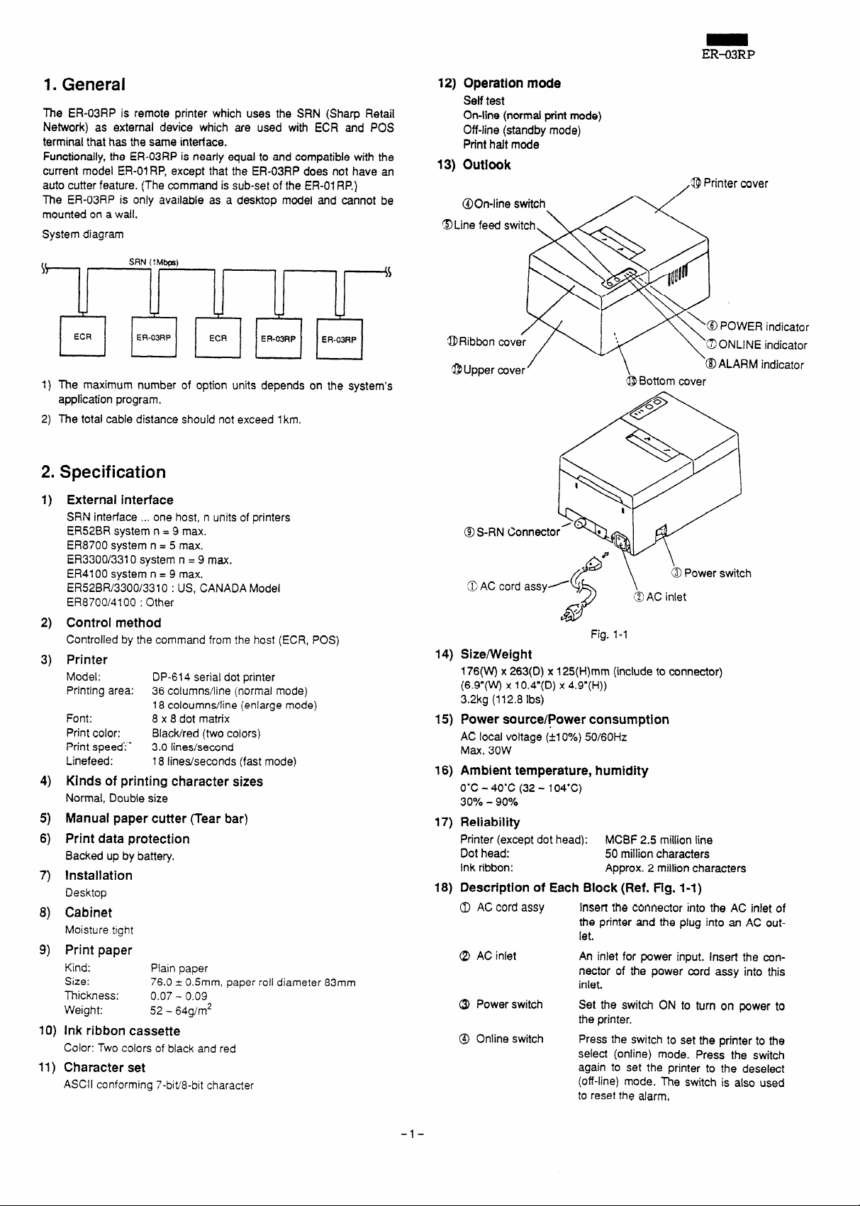
13)
outlook
@On-line switch.
@Line feed switch. \/. \
<opnntermver
ER43RP
,.
1) The maximum number of option units depends
application program.
2) The total cable distance should not exceed lkm.
(
2.
Specification
External interface
1)
SRN interface ... one host, n units of printers
ER525R system n = 9 max.
ER8700 system n = 5 max.
ER3300/331Osystem n = 9 max.
ER4100 system n = 9 max.
ER52BR/3300/3310 : US, CANADA Model
ER8700/4100 : Other
2)
Control method
Controlled by the command from the host (ECR,
Printer
3)
Model: DP-614 serial dot printer
Printing area: 36 columns/line (normal mode)
Font:
Print color:
Print speed”:”
Linefeed:
4)
Kinds of printing character sizes
Normal, Double size
Manual paper cutter (Tear bar)
5)
6)
Print data protection
Backed up by battery.
Installation
7)
Desktop
Cabinet
8)
Moisture tight
Print paper
9)
Kind: Piain paper
Size:
Thickness: 0.07- 0.0’3
Weight: 52- 64g/m2
Ink ribbon cassette
10)
Color: Two colors of black and red
11)
Character set
ASCII conforming 7-bit’8-bit character
SRN(lMbrs\
18 coloumns/line (enlarge mode)
8 x 8 dot matrix
Black/red (two colors)
3.0 lines/second
18 lines/seconds (fast mode)
76.0 ~ 0.5mm, paper roll diameter 83mm
on the system’s
Pos)
.
~ ‘~WER indicator
QRibbon cover
“~\::;:;;::;r
@Upper cover
OS-RN
.9
@AC cord assy~
Size/Weight
14)
176(W)
x 263(D) x 125(H)mm (include to connector)
(6.9”(W)
3.2kg (112.8 Ibs)
15)
Power source/Power consumption
AC local voltage (*1O%)50/60Hz
Max. 30W
16)
Ambient temperature, humidity
O“C-
30Y0- 90%
17)
Reiiabiiity
Printer (except dot head):
Dot head:
Ink ribbon:
18)
Description of Each Block (Ref. Fig. l-l)
0 AC cord assy
Q) AC inlet
@ Power switch
@ Online switch
X 10.4”(D) X 4.9”(H))
40”C (32 - 104”C)
$\
/
&
Insert the connector into the AC inlet of
the printer and the plug into an AC outlet.
An inlet for power input. Insert the connector of the power cord assy into this
inlet.
Set the switch ON to turn on power to
the printer.
Press the switch to set the printer to the
select (online) mode. Press the switch
again to set the printer to the deselect
(off-line) mode. The switch is also used
to reset the alarm,
@Bottom cover
\
@ Power switch
~ AC inlet
Fig. 1-1
MCBF 2.5 million line
50 million characters
Approx. 2 million characters
-1-
Page 4
ER-Q3RP
When the switch is pressed during the
printer operation, the printer is set to the
deselect mode after pfinting the current
line.
Setting the power switch ON with the online switch held down will initiate the
master reset operation.
Line feed switch
POWER indicator
(yellow green)
ONLINE indicator
(yellow green)
ALARM indicator
(red)
Connector
Printer cover
Ribbon cover
Upper cover
Bottom rover
Setting of Dip
Remove the bottom cover of the remote printer to acoess the three
8-position dip switches.
The following describes the dip switch functions.
Press the switch to feed the paper (in
the deseiect mode only). The switch is
used when loading new paper or when
typing space between lines.
Comes on when the power switch is set
ON, and goes off when it is set OFF.
Comes on when the printer is set to the
select (online) mode, and goes off when
it is set to the deselect (off-line) mode.
Printer operation is possible only when
the indicator is on.
Lights when the printer trouble O@ufred
or when the paper has depleted. When
the indicator turns on, both the printer
and line feed operations are disabled. To
reset this condition, either press the online switch or turn off and on the printer
power.
Used to connect the printer to the SRN
host via a cable. Check that the power is
off to both the printer and the SRN host
when connecting the cable.
Open the coverto replace the paper.
Open the coverto replace the ribbon.
switches
3-1. SWI (DSI)
Swl “1
SWI-2,3,4 Used to select the diagnostic program type.
Swl -2 SW1-3 SW1-4
ON ON
OFF
ON
OFF OFF
ON
OFF ON
ON OFF OFF
OFF OFF
●1 These two tests are collectively referred to as the SRN basic test.
The above dip switch settings are effective only when the diagnostic
mode is ON (SW1-7 ON). For deals of the diagnostic programs,
refer to Section 3-3.
Used to select CR mde enable/disable.
ON:
OFF:
ON
OFF ON RAM verifv
,
ON
CR code enabled
CR code disabled
ON
ROMIRAM test
ON
Hostterminal emulation mode
ON
Dip sw-tch’scantest
OFF
Print test
OFF
SRN flag continuous transmission *I
SRN packet continuous transmission
OFF
Line inspection program
Function
●1
SWI -5,6
Swl -7
SWI -8
Used to select the code conversion type
The remote printer provides two different types of code
conversion to handie the difference of code systems
between dissimilar machines. The switch is used to
select which type of code conversion to adopt.
Swl -5 SW1+6
OFF OFF
ON
OFF
ON
Used to set the diagnostic mode.
Upon power-on, the switch is scanned, and when the
switch is on, the diagnostic program is initiated in accordance with the setting of SW1-2,3,4.
ON I Diagnostic mode
OFF ~Normal operation mode
Used to set the auto cutter YES/NO.
The ON status of the switch indicates that the auto
cutter is used. Since the ER-03RP is not provided with
an auto cutter, the switch should always be set OFF.
OFF
ON No code conversion
, ON
Conversion type
Type 1
Type 2
No code conversion
3-2. SW2 (DS2)
SW2-1,2,3,4
SW2-5
SW2-6,7
SW2-8
L
Not used. All fixed to ON.
Used to select the SRN transmission speed.
OFF ~480 Kbps
ON
In the normal operation mode (SW1-7 OFF), the switch
state is scanned immediately after the master reset has
done, and is set in the SRN controller. Master reset
must therefore be done when the transmission speed
setting is changed.
in the diagnostic mode, the transmission speed is set
each time, immediately before the execution of the SRN
basic test or the host terminal emulation.
Used to set the carrier off monitoring time.
SW2-6 SW2-7
OFF i OFF
ON
OFF ‘ ON
ON
In the normal operation mode (SW1-7 OFF), the switch
is scanned immediately after the master reset has done,
and is set in the SRN controller. Master reset must
therefore be done when the timer setting is changed.
In the diagnostic mode, the timer is set each time, immediately before the execution of-the SRN basic test or
the host terminal emulation.
Not used. Fixed to OFF.
1 Mbps
OFF
ON
Tmer value
1 Mbps
6.4mS 12.8mS
4.8mS 9.6mS
3.2mS ]
1.6mS
480 Kbps
6.4mS
3.2mS
-2-
Page 5
ER-03RP
3-3. SW3 (DS3)
The dip switch is used to set the SRN terminal address.
In the normal operation mode (SW1-7 OFF), the switch is scanned
immediately after the master reset has done, and is set in the SRN
controller. Master reset must therefore be done when the address
setting is changed.
In the diagnostic mode, the address is set each time, immediately
before the executi~n of the SRN basic test.
Only in the case of executing the host terminal emulation in the
diagnostic mode, the address setting by the switch is used
address of the remote station.
The address is set using a binary number with the SW3-1 setting as
the most significant bit and the SW3-8 as the least significant bit.
as the
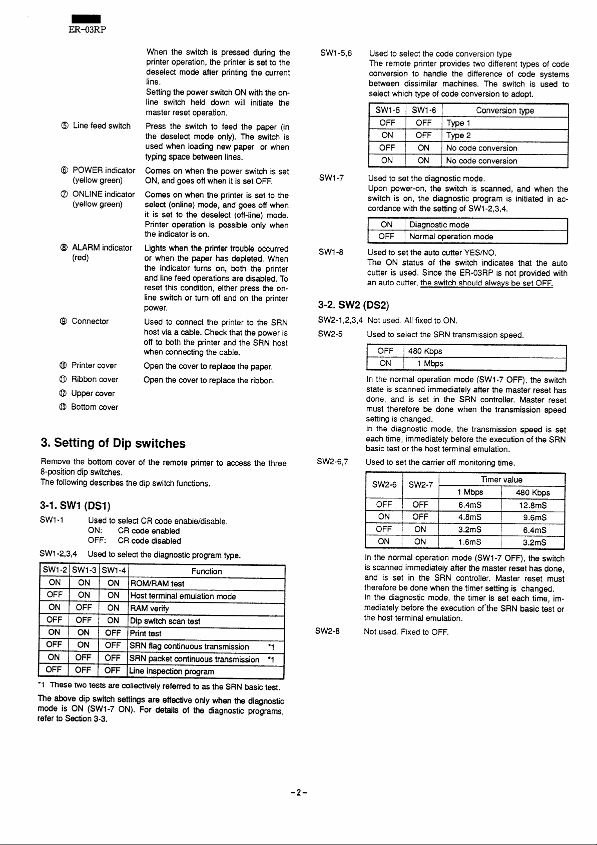
3-4. Dip switches DS1-DS3 factory setup
SWITCH
Swl -1 CR code (disabled)
SW1-2 I
Swl -3
SW1-4 I ‘ ‘
I
SW1-5 i
SWI-6 ~
SWI-7 \ Diagnostic mode (prohibited)
SW1-8 ! Auto cutter (NO)
I
I sw2-1 I
SW2-2
SW2-3
R
I
Selection of diagnostic program (line
inspection test) ------------
1
+Selection of conversion type (type 1) ,
Not used
Fixed to All “ON”.
I
Function Default
I
~--------:;:-
[
~
~-----------,
I
,
I
I
R
I
OFF
OFF
OFF
OFF
OFF
OFF
ON I
4. Disassembly procedure
4-1. Removal of upper cover and bottom cover
To remove the upper cover, remove the screws M3x6 (at four
1)
locations) shown in the figure and unfasten the connector with the
upper cover lifted up.
2)
Remove the screws M3x6 (at four locations) on both sides to
remove the bottom cover.
I
l\
SW2-5 I SRN transmission speed (1M bits) ~
$W2-6 I
SW2-7
SW2-8
SW3-1 I
t
1
I SW3-3 I
I
SW3-4 Terminal address (OOH)
SW3-5
H
I SW3-6 I
i
I
SW3-8 I
I
Carrier off timer (6.4ms)
Not used
I
1
I
I
/
]
.-_----_----
I
!
I
I
I
L------------4
~.
L------------A
L------------q
-------_----
1
L----.---95:
I
L------------q
!-------------+
~
ON
OFF
OFF
OFF
OFF
OFF I
OFF
OFF I
OFF ]
Fig, 4-1
I
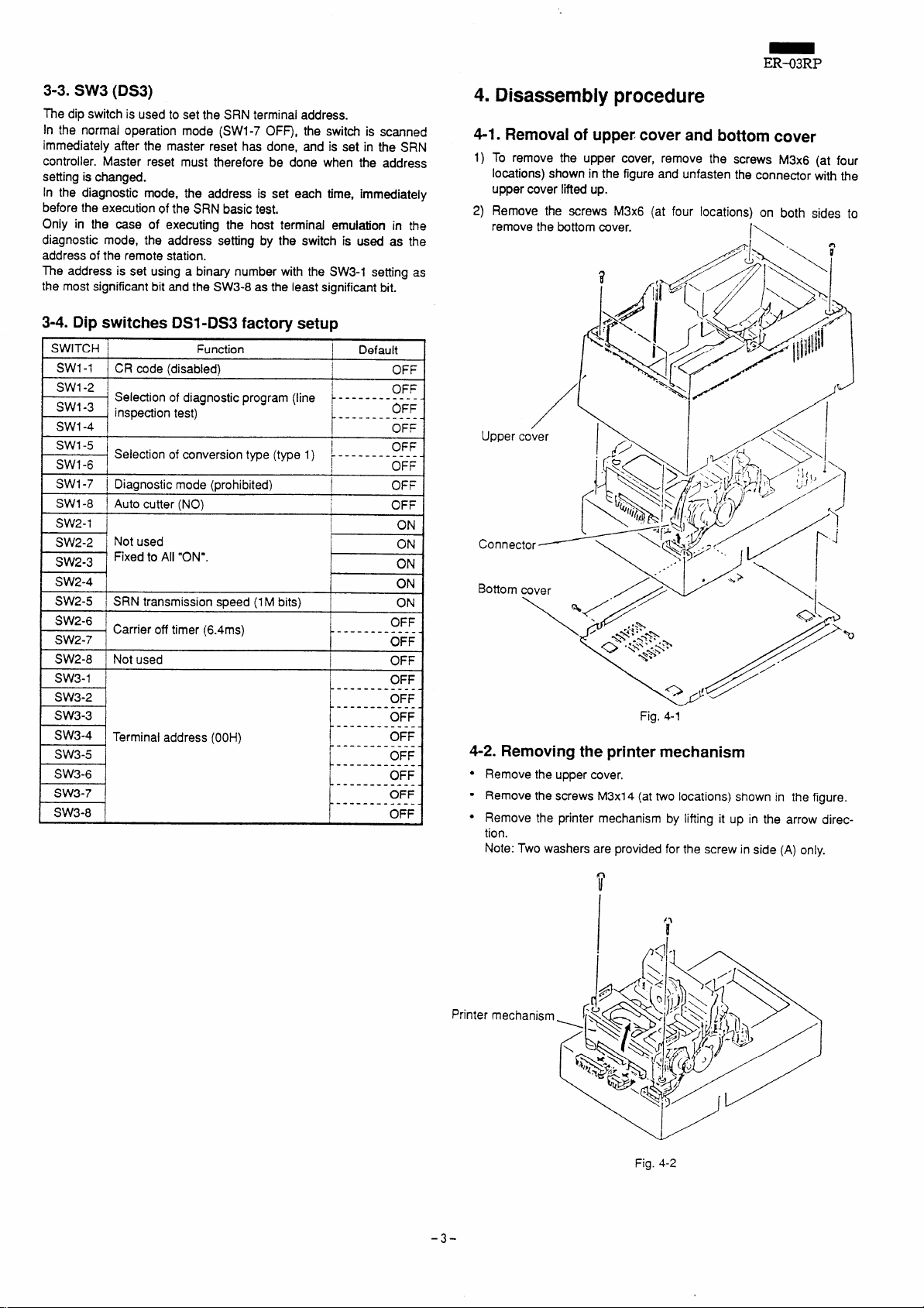
4-2. Removing the printer mechanism
● Remove the upper cover.
● Remove the screws M3x14 (at two locations) shown in the figure.
● Remove the printer mechanism by lifting it up in the arrow direc-
tion.
Note: Two washers are provided for the screw in side (A) only.
Printer
-3-
Fig. %2
Page 6
ER-03RP
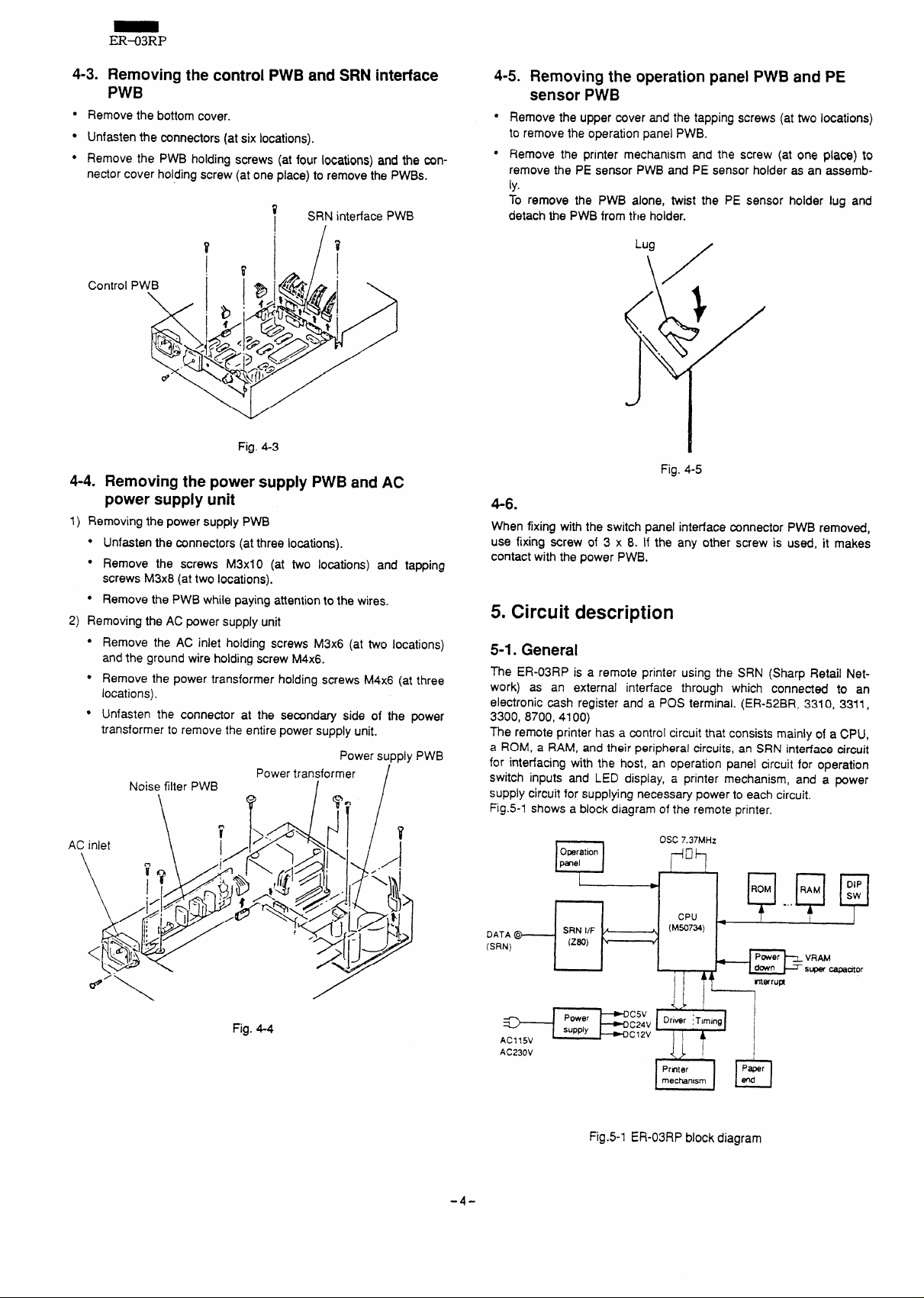
4-3. Removing the control PWB and SRN interface
PWB
●
Remove the bottom cover.
●
Unfasten the mnnectors (at six locations).
●
Remove the PWB holdina screws (at four locati~ns) and the connector cover holding scre; (at one place) to remove the PWBS.
?
SRN interface PWB
Control
Fig. 4-3
4-4. Removing the power supply PWB and AC
power supply unit
Removing the power supply PWB
1)
● Unfasten the connectors (atthree locations).
● Remove the screws M3x1O (at two locations) and tapping
screws M3x8 (attwo locations).
● Remove the PWB while paying attention to the wires.
2) Removing the AC power supply unit
●
Remove the AC inlet holding screws M3x6 (at two locations)
and the ground wire holding screw M4x6.
●
Remove the power transformer holding screws M4x6 (at three
locations).
●
Unfasten the connector at the secondary side of the power
transformer to remove the entire power supply unit.
Power supply PWB
Noise filter PWB
Power transformer
/
I
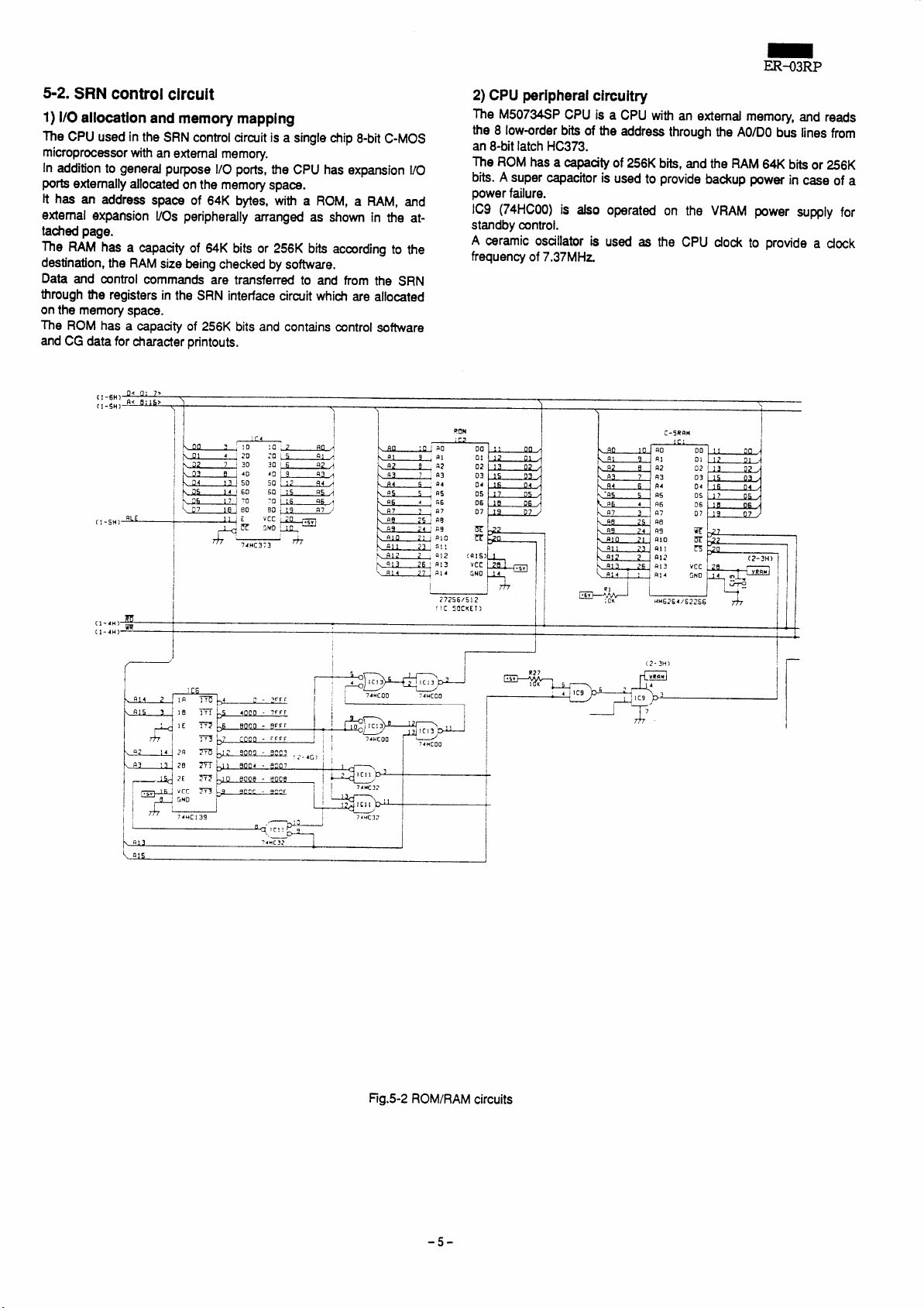
4-5. Removing the operation panel PWB and PE
sensor PWB
Remove the upper cover and the tapping screws (at two locations)
to remove the operation panel PWB.
Remove the printer mechanism and the screw (at one place) to
remove the PE sensor PWB and PE sensor holder as an assemb-
ly.
To remove the PWB alone, twist the PE sensor holder lug and
detach the PWB from the holder.
Fig. 4-5
4-6.
When fixing with the switch panel intedace connector PWB removed,
use fixing screw of 3 x 8. If the any other screw is used, it makes
contact with the power PWB.
5. Circuit description
5-1. General
The ER-03RP is a remote printer using the SRN (Sharp Retail Network) as an external interface through which connected to an
electronic cash register and a POS terminal. (ER-52BR, 3310, 3311,
3300, 8700, 4100)
The remote printer has a control circuit that consists mainly of a CPU,
a ROM, a RAM, and their peripheral circuits, an SRN interface circuit
for interfacing with the host, an operation panel circuit for operation
switch inputs and LED display, a printer mechanism, and a power
supply circuit for supplying necessary power to each circuit.
Fig.5-l shows a block diagram of the remote printer.
Fig. 4-4
-4-
m.?. a
AC230V
?
Opratlon
~el
/
SRNIIF
f
I
I
Fig.5-l ER-03RP block diagram
Osc7.37MHZ
,+il
*
(MS0734)
\
I .,
&,fi
CPU
7
..I-i
ROM RAM
Pmer ~VRAM
~-
r---- . .
Page 7
ER-03RP
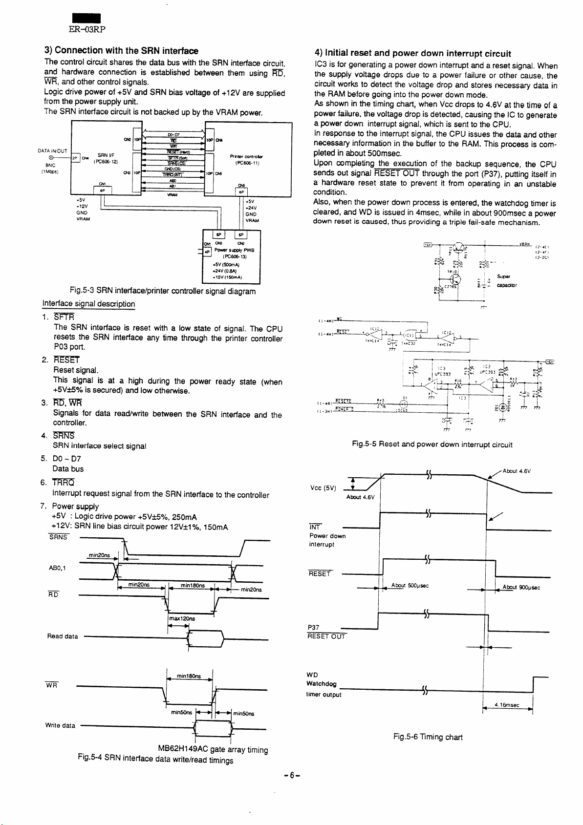
5-2. SRN control circuit
1) 1/0 allocationandmemorymapping
The CPU used in the SRN control circuit is a single chip 8-bit C-MOS
microprocessorwith an external memo~.
In addition to general purpose 1/0 ports, the CPU has expansion 1/0
PO* externally allocated on the memory space.
It has an address space of 64K bytes, w“th a ROM,
externalexpansion 1/0s peripherally manged as shown in the at-
tached page.
The RAM
destination, the RAM size being checked by software.
Data and control commands are transferred to and tiom the SRN
through the registers in the SRN interface circuit which are allocated
on the memory space.
The ROM has a capacity of 256K bits and contains control software
and CG data for character printouts.
hasa capacityof 64K bits or 256K bits according to the
a RAM, and
2) CPUperipheralcircuit~
The M50734SP CPU is a CPUwithanextemdmemory, and reads
the 8 low-order bits of the address through the AO/DObus lines from
an 8-bit latch HC373.
The ROM has
bits. A super capacitor is used to provide backup power in case of a
power failure.
IC9 (74HCOO)is also operated on the VRAM power supply for
standby control.
A ceramic osallator is used as the CPU dock to provide a dock
frequency of 7.37MHz.
acapaatyof256K bits, and the RAM 64K bits or 256K
~
( Qls
74”[00
7“F ‘
)
I
I
Fig.5-2 ROM/RAM circuits
-5-
Page 8
ER-03RP
3)ConnectionwiththeSRNinterface
The control circuit shares the data bus with the SRN interface circuit,
and hardware connection is established between them using ~,
~, and other control signals.
Logic drive power of +5V and SRN bias voltage of +12V are supplied
from the power supply unit.
The SRN interface circuit is not backed up by the VRAM power.
i
DATA INIOUT
o
~
BNC
[lM@s)
SRNIIF
2P W’u
(Wm-lz) (=606-11)
m
6P
I 1
+5V
I
Fig.5-3 SRN interface/printer wntroller signal diagram
Interface sianal descri~tion
1.
m
The SRN interface is reset with a low state of signal. The CPU
resets the SRN interface any time through the printer controller
P03 port.
2.
REsff
Reset signal.
~is signal is at a high during the power ready state (when
+5Vfie\e is secured) and low otherwise.
3.
m, m
Signals for data read/write between the SRN interface and the
controller.
4.
SRNS
SRN interface select signal
5.
DO- D7
Data bus
6.
TRRQ
Interrupt request signal from the SRN interface to the controller
7.
Power supply
+5V : Logic drive power +5V*5%, 250mA
+12V: SRN line bias circuit power 12V*1
““s 7
f
P
IWP ~
04!
IW
C#2
. -
m-07
m
m
WI
m
w
t
5-
RnWr COntrok
w
(PC6C6.13)
+5V (*N
+24V (IJm
+12V (l WA)
1
I I
t-
~m
,P - s- FWB
?“
Yo, 150mA
●5V
4)Initialresetandpowerdowninterruptcircuit
IC3 is for generating a power down interrupt and a reset signal. When
the supply voltage drops due to a power failure or other cause, the
circuit works to detect the voltage drop and stores necessary data in
the RAM before going into the power down mode.
As shown in the timing chart, when Vcc drops to 4.6V at the time of a
power failure, the voltage drop is detected, causing the IC to generate
a power down interrupt signal, which is sent to the CPU.
in response to the interrupt signal, the CPU issues the data and other
necessary information in the buffer to the RAM. This process is compieted in about 500msec.
Upon mmpieting the execution of the backup sequence, the CPU
sends out signal RESET OUT through the port (P37), putting itseif in
a hardware reset state to prevent it from operating in an unstabie
condition.
Aiso, when the power down process is entered, the watchdog timer is
cieared, and WD is issued in 4msec, whiie in about 900msec a power
down reset is caused, thus providing a tripie faii-safe mechanism,
w:
; 1-4H>
I
Fig.5-5 Reset and power down interrupt circuit
‘cc(’v)r-
Powerdown
interrupt
m
Readdata
Writedata
t
maw120n2
T
MB62H149AC gate array timing
Fig.5-4 SRN interface data write/read timinas
P37 r’~1
RESETOUT
WD
Watchdog
timeroutput
Fig.5-6 Timing chm
-6-
Page 9
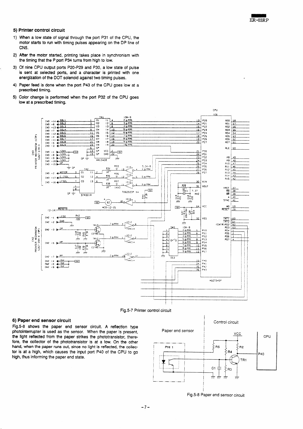
5)Printercontrolcircuit
1)
When a low state of signal through the port P31 of the CPU, the
motor starts to run with timing pulses appearing on the DP line of
CN5.
2)
After the motor statied, printing takes place in synchronism with
the timing that the Pport P34 turns from high to low.
3)
Of nine CPU output ports P20-P29 and P30, a low state of puise
is sent at selected ports, and a character is printed with one
energization of the DOT solenoid against two timing pulses.
4)
Paper feed
prescribed timing.
Color change is performed when the port P32 of the CPU goes
5)
low
is done when the port P43 of the CPU goes low at a
ataprescribed timing.
CM3 -14
CN3 -6
CH3-13
CN3-7
CM3-12
(N3 -4
CN3 -11
CN3 -5
CN3 -3
CM3 -i
CM3 -.9
,,,,,”:&;‘GpW~ ; ‘
+ 4V HRI 3408
.-
CN3 - 1s
CN3 -2
CN3 -17
CN3 -16
191
1OK-9
ER-03RP
CPU
---
P20
13
1s P23
I p24
1?,
1s P2S
P26
19
P27
20
‘ P30
21
22- P31
P32
23
i’
24 P33
XIN
X12UT
4s
d4
t
43
CN2 - I
CN2 -2
CN2 -3
CN2 -5
[N? -7
CN2 -4
CN2 .6
CN2 -9
54 HC14
Fig.5-7 Printer control circuit
6) Paperend
Fig.5-8
sensor circuit
shows
the paper end sensor circuit. A
reflection type
p~otointerrupter is used as the sensor. When the paper is present,
the light reflected from the paper strikes the phototransistor;, there-
fore, the collector of the phototransistor is at a low. On the other
hand, when the paper runs out, since no light is reflected, the collector is at a high, which causes the input port P40 of the CPU to go
high, thus informing the paper end state.
1
I
1
I
I
23
2A p.)
354
~ ~
end sensor ~
Paper
—.—.—.—.—. I
PHI 1
1
!
.,
i:
1.
I
I
—.—.—.—.—.
1
I
J
Fig.5-8 Paper end sensor circuit
V55
?!0
PI 1
P12
P13
P14
Pl!i
Pls
P17
P40
P42
1
I
1
I
I
m
0
$1
m
[CNTR) P02
P03
62
63 I
I
Control circuit
\tPP I
v Gu
-7-
Page 10
ER-03RP
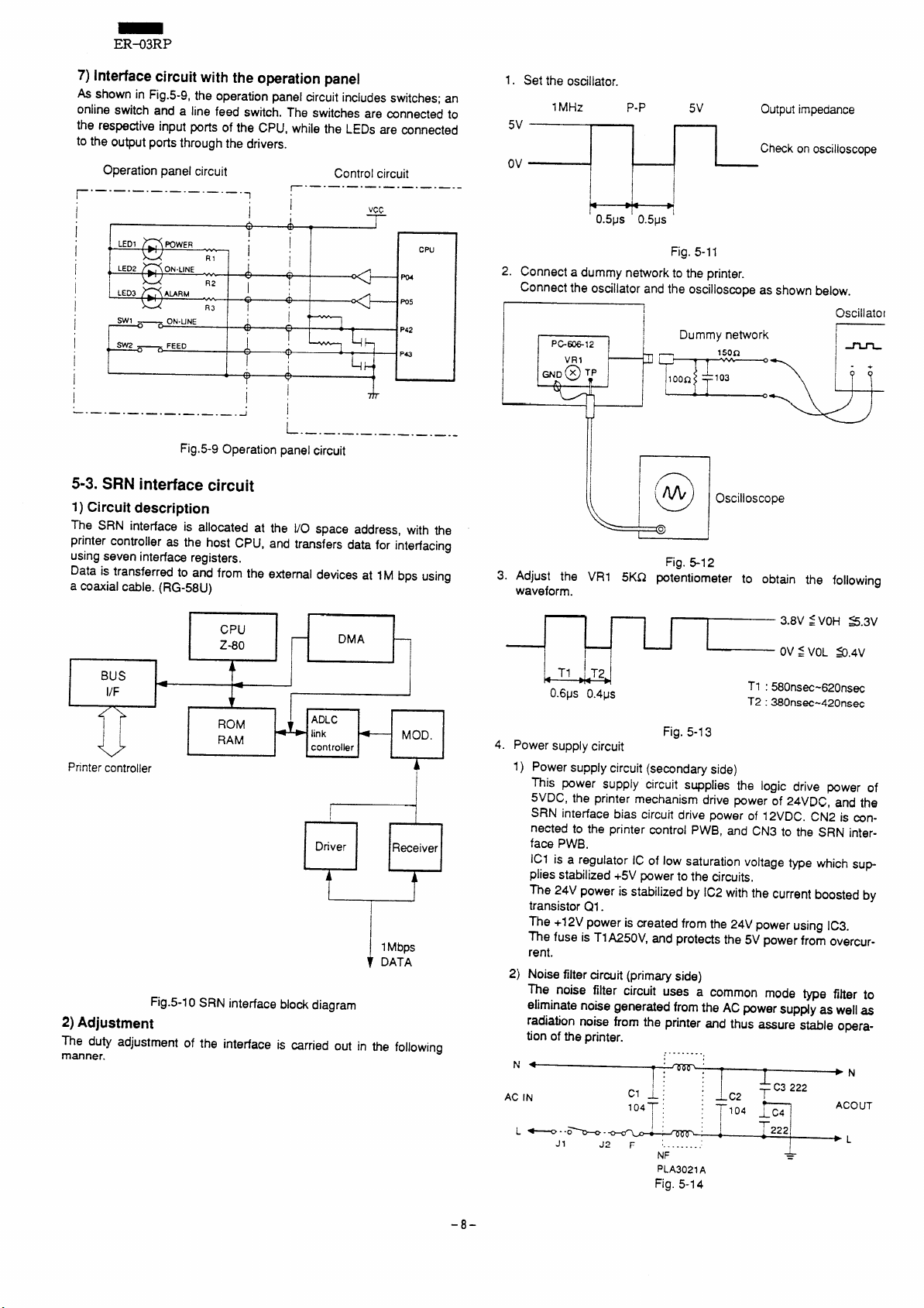
7)Interfacecircuitwiththeoperationpanel
shown in Fig.5-9, the operation panel circuit includes switches; an
As
online switch and a line feed switch. The switches are mnnected to
the respective input ports of the CPU, while the LEDs are connected
to the output ports through the drivers.
Operation panel circuit
.—.—.—.—.—.—.—.—.
r
I
,
I
LED1
nFQwER
,,
I
I
LED2
~ON-LINE
(I
LED3
~URM
i ,=.—O
I i;
-. —. —. —. —. —. —. —.—. J
ON-LINE
—
RI
R2
R3
1;
1!
w
i
“
1:
I
A
n
.
.
Y I T
L
Control circuit
.—.—.—.—.—.—.—. —.-
r
vc~
-
I
I
I
J
CPU
PD4
ms
P42
4
.—.—.—.—.—.—.—-—--
Fig.5-9 Operation panel circuit
5-3. SRN interface circuit
1) Circuit description
The SRN interface is allocated at the l/O space address, with the
printer controller as the host CPU, and transfers data
using seven interface registers.
Data is transferred to and from the external
devices at IM bps using
a coaxial cable. (RG-58U)
for interfacing
t 1 b I
CPU
Z-80
DMA
1. Set the oscillator.
1MHz
P-P
5V
Outputimpedance
5V
Checkonoscilloscope
Ov
L
P 1-
o.5ps o.5ps ‘
+
Fig. 5-11
2. Connect a dummy network to the printer.
Connect the oscillator and the oscilloscope as shown below.
PG-12
VR1
~D @ TP
[
I
Dummv network
Oscillator
I
@
3. Adjust the VR1 5KQ potentiometer to obtain the following
waveform.
Fig, 5-12
BUS
.? ‘
l/F
&
ADLC
link
controller
I
I
Driver
MOD.
A
Receiver
u
printer controller
ROM
RAM
b
TIP
[
I
1Mbps
I DATA
Fig.5-10 SRN interface block diagram
2)Adjustment
The duty adjustment of the intedace is carried out in the following
manner.
w
0.6ps 0.4ps
*
4. Power supply circuit
1)
Power supply circuit (secondary side)
Fig. 5-I 3
T1 : 580nsec-620ns~
T2 :380nsec-420nsW
This power supply circuit supplies the logic drive power of
5VDC, the printer mechanism dtive power of 24VRC, and the
SRN interface bias circuit drive
power of 12VDC. CN2 is mn-
nected to the printer control PWB, and CN3 to the SRN interface PWB.
ICI is a regulator IC of low saturation voltage type which sup
plies stabilized +5V power to the circuits,
The 24V power is stabilized by IC2 with the current boosted by
transistor Q1.
The +12V power is created from the 24V power using IC3.
The fuse is TlA250V, and protects the 5V power from overcurrent.
2)
Noise filter circuit (primary side)
The noise filter circuit uses a common mode type fiher to
eliminate noise generated from the
ACpower sup~y as well as
radiation noise from the printer and thus assure stable operation of the printer.
,.........,
●
N
AC IN
L/.~ --OL -~
JI
T :- : 1 T
cl i j j C2 ~
104 ; :
T
J2 F ‘.........’
NF
pLA3021A
‘1
: ~lo4 ~w
:J
-’- C3222
T222
i
=
➤ N
ACOUT
➤ L
Fig. 5-14
-8-
Page 11
ER-03RP
6. Printer unit description
6-1. Hints and tips in handling the printer
6-1-1. Hintsinusingtheprinter
Do not operate the printer
(1)
paper and ink ribbon. Printing without
damage the printhead and platen surface, deteriorate the print
quality, and
(2)
Do not try to move the print head by hand. Since the belt that
drives the print head is directly coupled with a gear train, the belt
and the carnage drive pipe will be subjected to overload
the print head is
and other trouble.
(3)
Since the printer uses a permanent magnet (in the motor) and
an electromagnet, avoid using the printer in a location that may
be subjected to a large amount of iron filings, dust, dirt, etc.
Printed circuit boards are mounted in the bottom of the orinter.
(4)
Take care so that the printed circuit boards do not c~me in
contact with the case or foreign materials do not adhere to the
boards.
shorten the printer life.
moved by hand, leading to timing misalignment
6-1-2. Hints in storing the printer
(1)Do not store the printer in a location where a large amount of
or dirt, high temperature, or high humidity is encountered.
dust
6-2. How to load the paper
Use paper of prescribed standard.
6-2-1. Paperleadedgefinish
Cut the paper lead edge straight. (See figure below)
If the paper cannot be smoothly taken up by the paper feed roller, fold
back the paper lead edge for ease of insertion.
o
6-2-2.How to loadthe rollpaper
Load the paper as shown below.
when the printer is not loaded with
paper or ink ribbon will
when
x
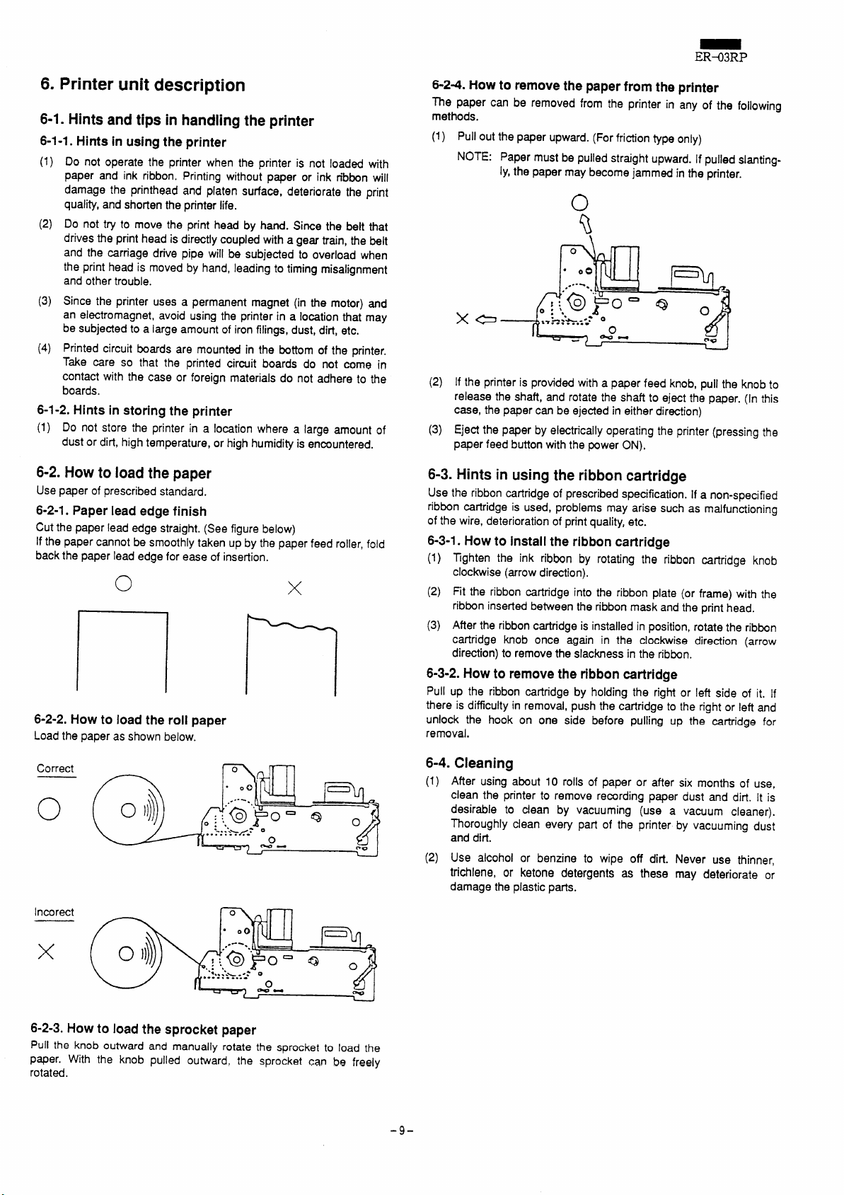
6-24. How
The paper can be removed from the printer in any ofthe following
methods.
(1) Pull out the paper upward. (For fridion type only)
to removethepaperfromthe printer
NOTE: Paper must be pulled straight upward. If pulled slanting-
ly,the paper may become jammed in the printer.
\
1““Qllw1I
(2) If the printer is provided with a paper feed knob, pull the knob to
release the shaft, and rotate the shaft to eject the paper. (in this
case, the paper can be ejected in either direction)
(3) Eject the paper by electrically operating the printer (pressing the
paper feed button with the power ON),
6-3. Hints in using the ribbon cartridge
Use the ribbon cartridge of prescribed specification. If a non-specified
ribbon cartridge is used, problems may arise such as malfunctioning
of the wire, deterioration of print quality, etc.
6-3-1. Howto installtheribboncartridge
Tghten the ink ribbon by rotating the ribbon cartridge knob
(1)
clockwise (arrow direction).
(2) Fit the ribbon cartridge into the ribbon plate (or frame) with the
ribbon inserted between the ribbon mask and the print head.
(3) After the ribbon cartridge is installed in position, rotate the ribbon
catiridge knob once again in the clockwise direction (arrow
direction) to remove the slackness in the ribbon.
6-3-2.Howto removetheribboncartridge
Pull up the ribbon cartridge by holding the right or left side of it. If
there is difficulty
unlock the hook on
removal.
in removal, push the cartridge to the right or left and
one side before pulling up the cartridge for
Correct
o
Incorect
x
6-2-3. How to load the sprocket paper
Pull the knob outward and manually rotate the sprocket to load the
paper. With the knob pulled outward, the sprocket can be freely
rotated.
6-4. Cleaning
(1)
(2)
-9-
After using about 10 rolls of paper or after six months of use,
clean the printer to remove recording paper dust and dirt. It is
desirable to clean by vacuuming (use a vacuum cleaner).
Thoroughly clean eve~ part of the printer by vacuuming dust
and dirt.
Use alcohol or benzine to wipe off dirt. Never use thinner,
trichlene, or ketone detergents as these may deteriorate or
damage the plastic parts.
Page 12
ER-03RP
7. Overview and operating principle of the
printer
7-1. Overview
7-1-1.Features
The DP614 printer is a compact serial dot printer, and has the following features.
(1) Compact, light weight, and low power consumption.
(2) High speed printing, crisp printing by high reliability 7-pin head,
and bidirectional printing method.
(3) Paper insertion in both directions, from the rear and from the
bottom. (for friction type only)
Generalspecification
7-1-2.
1.
Printing method
Serial impact dot matrix printing method
2.
Printing direction
Bi-directional (unidirectional for graphic printing)
Printing speed
3.
3.0 iines/sec.
(At motor voltage +25V, +25*C)
4.
Print format
1) Character matrix 7x7 (including half dots)
2) Dot composition
180 (360) dots/line
Numbers in parentheses include haff dots.
3) Print columns and character size
40 columns 1,4(W) x 2.4(H)mm
5.
Color change
Color change is accomplished by energizing the color change
solenoid.
1) Voltage:
Resistance:
6.
Paper feed
1) Voltage:
Resistance:
2) Paper feed pitch
3) Quick paper feed
7.
Recording paper
1)
Type
2)
Kinds of paper
3)
Recommended paper
(Cutform paper) 45-55kg/l 000 sheets (1091x788mrn/sheet)
(Copy paper) Non-carbon paper
Friction type:
Pin wheel type:
Inking
8.
9. Motor
10. Printhead
*1 070
24ti VDC
33*3Q (25&)
24~~VDC (across solenoid termin~s)
33*3Q (25-C)
4.23mm (1/6”)
2.82mm (1/9”) for graphic type
Approx. 18 lines/see.
Friction type:
Pin wheel type: Fan fold paper
Special cartridge ribbon, red/black two-color or black
monocolor
DCbrush motor
Voltage:
Current:
Number of wires:9
Wire diameter: 0.3mm
Wire pitch:
Solenoid:
Resistance:
Roll paper
76m@.5mm, (width)
$83mm (outer dia.)
Width 76mm (3”) to 89mm (3.5”)
Plain paper and non-carbon paper
One original + one copy
One original + two copies
Total thickness 0.2mrn max.
24t4 VDC
Peak current Approx. 1A
Average current 0.2A max.
0.353mm
Voltage 24*1 VDC
17Q (25*C)
11. Overall dimensions
12. Weight
13. Reliability Printhead life:
Printer mechanism: MCBF 2.5 million lines
14. Operating temperature
137(W) x 136(D) x 63.5(H)mm
(5.4”(~
Approx. 690g (1,5 Ibs)
X 5.35”(D) X 2.5(H))
50 million characters
o to +50”C
7-2. Mechanism and operating principle
7-2-1.Outlineof mechanism
The printer mechanism mnsists of the following nine blocks.
(1)
Frame block
(2)
Motor block
(3)
Power transmission mechanism block
(4)
Sensor mechanism block
(5)
Head feed mechanism block
(6)
Printhead mechanism block
(7)
Paper feed mechanism block
(8)
Ribbon mechanism block
(9)
Color change mechanism block
Mechanismandoperatingprinciple
7-2-2.
Of the above nine biocks, seven mechanism blocks excluding the
frame and motor blocks are described next for their structures and
operating principles.
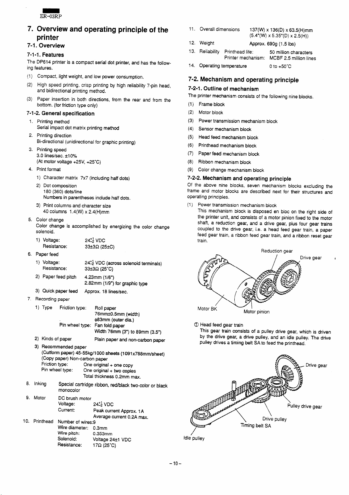
(1) Power transmission mechanism block
This mechanism block is disposed en bloc on the right side of
the printer unit, and consists of a motor pinion fixed to the motor
shaft, a reduction gear, and a drive gear, plus four gear trains
coupled to the drive gear, i.e. a head feed gear train, a paper
feed gear train, a ribbon feed gear train, and a ribbon reset gear
train.
Reduction gear
gear
@ Head feed gear train
This gear train consists of a pulley drive gear, which is driven
by the drive gear, a drive puliey, and an idle pulley. The drive
pulley drives a timing belt SA to feed the printhead.
Drive gear
ive gear
ldl~pulley
-10-
Page 13
ER-03RP
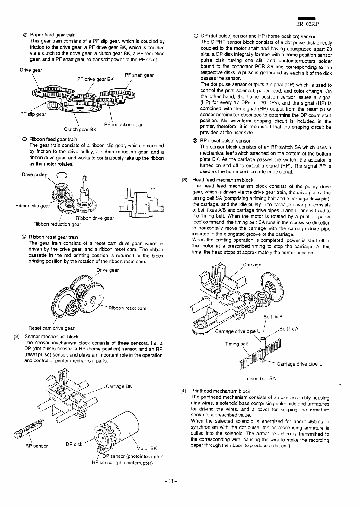
Paper feed gear train
This gear tr~n consists of a PF slip gear, which is coupled by
friction to the drive gear, a PF drive gear BK, which is coupled
via a cfutch to the drive gear, a clutch gear BK, a PF reduction
gear, and a PF shaft gear, to transmit power to the PF shaft.
Drive gear
\
Si
PF
PF drive gear
\
Clutch gear
, /
PF reduction gear
BK
BK
PF shaft gear
@ Ribbon feed gear train
The gear train consists of a ribbon slip gear, which is coupled
by friction to the drive pulley, a ribbon reduction gear, and a
ribbon drive gear, and works to continuously
take up the ribbon
asthe motor rotates.
Drive pulley
Ribbon slip gea
Ribbon reduction gear
Ribbon reset gear train
@
The gear train consists of a reset cam drive gear, which is
driven by the drive gear, and a ribbon reset cam. The ribbon
cassette in the red printing position is returned to the black
printing position by the rotation of the ribbon reset cam.
o
\
/
0
Ribbon drive
gear
Drive gear
DP (dot pulse) sensor and HP (home position) sensor
The DP/HP sensor block consists of a dot pulse disk directly
coupled to the motor shaft and having equispaced apart 20
slits, a DP disk integrally formed with
ahome position sensor
pulse disk having one slit, and photointerrupters solder
bound to the mnnector PCB SA and corresponding to the
respective disks. A pulse is generated as each slit of the disk
passes the sensor.
The dot pulse sensor outputs a signal (DP) which is used to
the print solenoid, paper feed, and mlor change. On
control
the other hand, the home pcsition sensor issues a signal
(HP) for every 17 DPs (or 20 DPs), and the signal (HP) is
combined with the signal (RP) output from the reset pulse
sensor hereinafter described to determine the DP count start
position. No waveform shaping circuit is included in the
printer, therefore, it is requested that the shaping circuit be
provided at the user side.
RP (reset pulse) sensor
The sensor
mechanical !eaf switch
block consists of an RP switch SA which uses a
attached on the bottom of the bottom
plate BK. As the cm-age passes the switch, the actuator is
turned on and off to output a signal (RP). The signaf RP is
used as the home position reference signal.
(3)
Head feed mechanism block
The head feed mechanism block consists of the pulley drive
gear, which is driven via the drive gear
train, the drive pulley, the
timing belt SA (mmprising a timing belt and a carriage drive pin),
the carriage, and the idle pulley. me carriage drive pin consists
of beit fixes WB and carriage drive pipes U and L, and is fixed to
I
the timing belt. When the motor is rotated by a print or paper
feed command, the timing belt SAruns in the clockwise direction
to horizontality move the carriage with the carriage drive pipe
inserted in the elongated groove of the carriage.
When the printing operation is completed, power
is shut off to
the motor at a prescribed timing to stop the carriage. At this
time, the head stops at approximately the center position.
Ribbon reset cam
/
cam drive gear
Reset
(2)
Sensor mechanism block
The sensor mechanism block consists of three sensors, i.e. a
DP (dot pulse) sensor, a HP (home position) sensor, and an RP
(reset pulse) sensor, and plays an important role in the operation
and control of printer mechanism parts.
HP sensor (photointerrupter)
otor BK
nterrupter)
-11-
Timing
rriage drive pipe L
SA
(4)
Printhead mechanism biock
Tming belt
The printhead mechanism tinsists of a nose assembiy housing
nine wires, a solenoid base comprising soienoids and armatures
for driving the wires, and a cover for keeping the armature
stroke to a prescribed vaiue.
When the selected soienoid is energized for about 450ms in
synchronism with the dot pulse,
the corresponding armature is
pulied into the soienoid. me armature action is transmitted to
the corresponding wire, causing the wire to strike the recording
paper through the ribbon to produce a dot on it.
Page 14

ER-03RP
Ifl /p”n’
‘T
Nose assembly/
Paper feed mechanism
(5)
The paper feed mechanism consists of the paper feed power
transmission mechanism described in 2-2-2. (l)-(2), a paper
feed solenoid which controls the clutch mechanism, a PF
lever, and a clutch cam. The
The clutch mechanism has a spring clutch, consisting of a PF
drive gear BK, a clutch gear BK, a clutch spring, and the clutch
cam, to transmit the rotation of the clutch gear BK to the PF
drive gear BK.
Two paper feed methods are available for the printer, the friction
method and the pin wheel method.
Drive
PF slips
PF slipgea’r
Clutch cam I
\Solenoid base
PF shaft is driven to feed the paper.
PF shaft
\
,=”L
‘ <i
;)
.
//
Clutch spring
o
5
stopper
spring
PF shaft gear
Paper feed
solenoid
PF trigger lever
0
\
Clutch gear BK
trigger
[Paper feed overload protection mechanism]
A safety mechanism is provided to prevent gear breakage
and motor coil burning due to the motor seizure in case
overload is applied to the PF shaft because of p~er jam,
etc. The PF slip gear is coupled by friction to the drive gear
via the PF slip spring, and is so constructed that when the PF
shah is subjected to a greater load than a prescribed torque,
it slips on the PF shaft to absorb the overload.
,Side plate R
tve gear
slip
PF
y\
[Paper release mechanism]
me PF shaft gear is coupled to the PF ratchet fixed to the
PF shaft so that the ratchet engagement is released when
the paper is pulled in the forward direction, thus allowing the
paper to be smoothly pulled out. Also, if a knob is mounted
on the PF shafi, the ratchet engagement can be released by
pulling the knob outward, thus allowing the PF shaft to be
freely rotated. In this situation, the paper can be fed in either
forward or reverse directions by rotating the knob.
slip gear
Pivot drive gear
\
0 Friction type (Type D/P61*-*F*)
The friction type consists of two PF rollers fixed to the PF
shaft, pressure rollers press-contracting the respective PF
rollers, and pressure roller springs applying pressure to the
respective pressure rollers. Paper is fed by the friction force
acting between the PF rollers and the pressure rollers, Paper
can be inserted either from the rear or from the bottom.
aft
gear
do
o
A
‘u ”Rear
t
Pressure roller spring
Bottom
PF ratchet
(6)
Ribbon mechanism block
The mechanism block consists of a ribbon cartridge in which an
endless ribbon is housed, a ribbon feed gear train, and a ribbon
drive pole SA which is driven by the ribbon feed gear train.
When the motor is in rotation, the ribbon drive pole SA is continuously rotated via the gear train, to drive the ribbon gear
contained in the ribbon cartridge so that the ribbon is continuously taken
The ribbon drive pole SA is coupled to the ribbon drive gear via
a ratchet, so that it can be rotated freely in the direction in which
the ribbon is taken up (in the forward direction). Therefore, the
cartridge knob can be rotated to take up the ribbon with the
ribbon cartridge installed in the printer.
up.
PF shaft gear
-12-
Ribbon drive gear
Page 15

The two-color ribbon cartridge (D type) is mounted on the ribbon
plate, and the mono-color type (M type) on the frame,
Mono-color ribbon cartridge mounted in position
Two-color ribbon cartridge mounted in position
ER-03RP
(7) Color change mechanism block (for Dtype only)
The mechanism block consists of a ribbon plate on which to
mount a ri~on cartridge, a color change lever,
solenoid, a ribbon reset cam, and a reset cam drive gear.
In normal operating condition, the ribbon plate is locked in position by the lower hook of the color change lever,
black ribbon area in the printing position. When the mlor change
solenoid is energized through a red print command, the color
change lever is pulled in to disengage the lower hook from the
ribbon plate. The mior change lever swings upward by the force
of the color change lever, hitting the upper hook of the color
change lever. The ribbon plate is thus retained by the upper
hook, setting the red ribbon area in the printing position for red
printing. When the printing is completed, the ribbon plate is
pulled downward by the ribbon reset cam, engaged with the
lower hook of the color change lever, and reset to the original
position (black printing position).
The timing is so set that the ribbon reset cam will be operated
when the printhead is in a non-printing area at the extreme right
or left, to avoid accidental resetting during printing.
a color change
holdingthe
change
or
solenoid
[Safety mechanism]
If the ribbon gear binds because of a ribbon jam, the motor
may be subjected to overload, causing gear tooth breakage,
motor coil burning, and other troubles. To prevent such
troubles, the ribbon slip gear is coupled by friction to the
drive pulley via the ribbon slip spring, and is so constructed
that it slips in the drive pulley when the r!bbon feed system is
subjected to overload.
Drive pull
Fixed
Ribbon slip spr
Ribbon slip g
Color ch’angespring
-\
Ribbon reset
cam
e lever
[Black printing]
uIIin
d printing]
[Resetting]
I
Fixed
-13-
Page 16

ER-03RP
8. Troubleshooting
Repairing procedure
8-1.
Repairs should be done in accordance with Section 3 “Troubleshooting chart” after acquiring working knowledge of the operating principle
and construction of the printer.
Also refer to 8-2 “Connector and wiring diagrams” which should
facilitate the check and repair work. - -
8-2. Connector and wiring diagrams
8-2-1.Connectordiagram
4286
diagram
Printhead SA
Head FPC
Connector C
SOL4
1
2
SOL2
3 SOL6
4
SOL6
5 SOL9
r
6 + 24V
7 + 241’
8 + 24V
9 SOL?
)0 Sou
11 Sou
12
SOLI
13 F CND
I
Connector PCB SA
l[y[
I I
~ i
i,
I
Ii
T
MA
5
6 \ SOL2
I
7 Soti
8 I +24V
9 + 24V
10 + 24\’
1$ PF @ii ‘
17 cc on!
cc~
10
connector B
rOcontrol biOck
1
17
Connector A
Connector PWB SA
UKOG-6669RCZZ
L
1
DP sensor
k
1
J
●
(
Y HPsensor
+w~ i
1
(F
Validation (option)
L
I
1
I
1
T
l~Jl[’~-
RP sensor paper end (op~ion)
J
-14-
Tomntrol
block
J
Wiring diagram
Page 17

8-3.Troubleshootingchart
8-3-1.Headfeedtrouble
Phenomenon
Carriage does not
move
Carriage does not stop DP/HP/RP signal
Symptom
Motor does not run Motor defective
Motor runs
Possible cause
Applied voltage to
motor not normal
Connector PCB SA
defective
Paperjam
Printhead w“re caught Check if wire gets caught. Replace printhead SA.
in ink ribbon or paper
Foreign matter caught Manually rotate motor pinion to check if
in gear wheel train or
broken gear causing
action failure
~ming belt SA and Remove carriage BK and check if
pulley out of phase carriage drive pin and pulley timing belt SA.
Carriage bearing
trouble
DP/HP/RP signal
I abnormal
abnormal and its output waveform. Also check replace sensor, or
Trouble in control block ‘ Check hardware circuit in control block
ER-Q3RP
Checking procedure
Apply rated voltage across soldered
motor leads @(red)
solder side of connector
PCB SAto &eck if motor runs.
Check voltage across pin 1 (~) and pin
2 (~) of ~nnector A on connector PCB
SA to see if applied voltage is normal.
Check for continuity between pin 1 of
connector A and motor lead (red) and PCB SA.
between pin 2 and motor lead (black).
Remove printhead and checkfor
jammed paper or foreign matter.
gear train moves smoothly. matter, etc. or replace
engagement is not out of phase.
Check if carriage rail (front and rear) is
i lubfi~ted and if ~rriage r~l moves
i smoothly when turned by hand. oil, or replace carriage
Check voltage applied to each sensor Repair control block,
and its output waveform. Also check replace sensor, or
connector PCB SAfor continuity. replace connector
Check voltage applied to each sensor
connector PCB SAfor continuity.
and wiring from control block.
and ~(black) on
I Adjust position of
I matter, etc. and apply
replace connector
Repair control block or
rectify wiring.
Remedy
Replace motor.
Repair control block.
Replace connector
Remove foreign
matter, etc.
(Also replace ribbon
cassette if wire gets
caught in ribbon)
Remove foreign
broken gear.
Remove foreign
BK and carriage rail.
PCB SA.
Repair control block.
PCB SA.
8-3-2.Printing trouble
Phenomenon
Cannot print (ail dots
or particular dots)
Symptom
Carriage motion is
normal failure
Head FPC connection
Printhead SA defective
Improper mounting of
ink ribbon I
“
DP/HP/RP signal
abnormal
Trouble in control block Check hardware circuit in control block
Connector PCB SA
defective
Foreign matter caught
in printing area
Deformation or Remove printhead SA and check ribbon
improper mounting of
ribbon mask
Possible cause Checking procedure Remedy
Check connection of FPC.
Replace printhead SA with a new one Replace printhead SA.
and check the result.
, Check mounting condition of ribbon.
Check voltage applied to each sensor Repair control block,
and its output waveform. Also check replace sensor, or
connector PCB SAfor mntinuity. replace connector
and wiring from control block.
Check for continui~ between cunnector I
A and connector B. (Refer to 8-2. Wiring
diagram)
Remove printhead SA and check printing
area for foreign matter.
mask for deformation and mounting
I condition.
-15-
Firmly insert FPCto
establish proper
connection.
‘ Mount ink ribbon
correctly.
PCB SA.
Repair control block or
rectify wiring.
Replace conne~or
PCB SA.
Remove foreign
matter.
Replace or properly
mount ribbon mask.
Page 18

Phenomenon
Printed characters too
light
3i-directional printing
nisafignment
9
Symptom ~
No ribbon feed
[ cassette.
Ribbon feed is normal
Misalignment
than 3.5 columns (17
dots)
Misalignment inside of
2 dots (misalignment
inside of 0.3mm is
within specification)
greater
Possible cause ~
~Improper mounting of
ribbon cassette
Ribbon cassette
defective
Foreign matter caught
in ribbon drive
mechanism or broken ~smoothly.
gear causing action ~
Troubie in ribbon slip ~
mechanism
Improper gap
, between printhead
I and platen
Trouble in controlblock I Check voltage ~plied from control block
Improper mounting
‘Sition OfRp sensor
Improper mounting
position of connector
PCBSA
~Check mounting condition of ribbon
1cassette.
I
! Rotate ribbon cassette
~arrow direction to check knob operation
\ and ribbon takeup condition.
t Manually rotate motor pinion
~toward you to check if gear train moves
t
I
With ribbon cassette mounted in
~position, manually rotate motor pinion in
~direction toward you to check if ink
ribbon is taken up properly.
Check gap
I platen.
~.
~as well as voltage added time.
I
i Try to shift RP sensor mounting position
I to left or right to check if bidirectional
I
prlntlng misalignment is corrected.
; Tryto shift connector PCB SAforward or
~backward to check if biairectionai
; printing misalignment is corrected.
I
Checking procedure
takeup knob in
in direction
between printhead and
Properly mount ribbon
cassette.
Replace ribbon
Remove foreign
matter, etc. and
I replace broken gear.
I I
Replace ribbon slip
mechanism.
gap.
‘ Adjust
Repair control block.
Readjust RP sensor.
Readjust connector
PCB SA.
Remedy
;-3-3.Paperfeedtrouble
Phenomenon
Cannot insert paper
I
Paper feed does not
operate at all or fails
to operate sometimes
paper feed pitch
improper
Symptom
PF coil does not pull in
PF coil puIIsin
Paper feed pitch too
great
Possible cause
paper lead edge is
bent or improperly cut ~and cut straight.
Trouble because of !
non-standard paper
Trouble because of ,
paper dust or foreign
matter
Improper loading of
paper on pin wheels
G~ between pF coil
and PF trigger lever is
too wide
PFcoil defective
Connector PCB SA
defective
Trouble in control biock ~Check hardware circuit in mntrol block
Trouble be~use of
paper jam
Gap between PF coil ,
and PFtrigger iever is i trigger iever.
too smali
Troubie in paper feed ~Check if p~er feed mechanism has not I Remove foreign
mechanism
Troubie in ciutch
mechanism
!
‘ Check that paper lead edge is not bent
Check thickness, width, and diameter of
paper used.
Check paper feed route for dust and
~foreign matter.
I
Check if guide holes of paper are
I engaged with pin wheels properly
(symmetrically and without beingstretched too tight or compressed too
i loose).
~Check gap between Pi mil and PF
trigger lever.
,
I Check resistance of PF coil.
~(Specification: Approx. 30Q)
~Checkfor continuity between solder part
‘ on connector PCB SA and connector A.
: and wiring from control biock.
: Check paper feed route and paper
~ioading condition.
1
I
Check gap between PF coii and PF
~seized up because of foreign matter or
broken gear, or if PF siip mechanism is
‘ generating enough force to feed paper.
I Check ciutch gear BK, drive gear BK,
~and clutch spring for abnormal wear and
I other defects.
Checking procedure
Remedy
Insert paper properly
once again.
Use paper of
prescribed
specification.
Remove paper dust
and foreign matter.
Load paper pr.r-,.,.
I Readjust gap between
PF coil and PF trigger
I lever.
Repiace PF coii.
Repiace connector
PCB SA.
Repair control block or
I rectify wiring.
i Rectify paper feed
route and ioad paper
I correctiy.
Readjust gap between
PF coii and PF trigger
I iever.
matter, repiace broken
gear, or repiace PF
siip mechanism.
Repiace defective
parts.
‘nnQrlv
-16-
Page 19

8-3-4.
Ribbonfeedtrouble
Phenomenon
No ribbon feed
8-3-5. Color changetrouble
Phenomenon
No red printing
No color change
Symptom
Symptom Possibie cause
Possible cause
Improper mounting of
ribbon cassette
Ribbon cassette
defea”ve
Foreign matter caught
in ribbon drive
mechanism or broken
gear causing action
failure
Trouble in ribbon siip
mechanism
I Maladjustment of
color change timing
I
ER-03RP
Checking procedure
Check mounting condition of ribbon Properly mount ribbon
cassette. cassette.
Rotate ribbon cassette takeup knob in
arrow direction to check knob operation
and ribbon takeup condition.
Manually rotate motor pinion in direction
toward you to check if gear train moves
smoothly.
With ribbon cassette mounted in Replace ribbon
position, manuaily rotate motor pinion in I
direction toward you to check if ink
ribbon is taken
With prfnthead positioned at extreme left,
check if registration mark (0)on ribbon
reset cam is aligned with engaging
position with reset cam drive gear.
up properly.
Checkinq orocedure
I
!
~Realign registration
! mark.
Remedy
Replace ribbon
cassene.
Remove foreign
matter, etc. and
replace broken gear.
slip
mechanism.
Remedv
Mixed coior printing
Mixed coior printing /
I
‘ Maladjustment of CC
=
defective
Trouble in control block
I
I
I Maladjustment of
! mior change timing
I
I
I
Ribbn mask sh~e
\
1defective
/
I
b
I faiiure
+eset cam drive gear Ribkn reset cam ~
With CC lever puiled in CC coii, check
gap between ribbon plate and CC lever.
Check resistance of CC roil.
(Specification: Approx. 30Q)
Check for continuity between soider part
on connector PCB SAand connector A.
Check hardware circuit in controi block
and wiring from control block.
With printhead positioned at extreme left, / Readjust registration
check if registration
reset cam is aligned with engaging
position with reset cam drive gear.
+ 0+
cm
Reset cam drive gear Rib&n reset cam
With paper and ribbon loaded in position, ~Replace ribbon mask.
carefully move ribbon piate up and down ~
to check if ribbon does not catch ribbon ~
mask.
Check if CC lever operates smoothiy. ~Replace parts or
mark (0)on ribbon
Registration
mark
A
~Readjust gap.
I Replace CC coil.
Repiace connector
PCB SA.
I Repair control block
I and rectify wiring.
mark.
I
~make corrections.
-17-
Page 20

ER--O3RP
9. Disassembly and reassembly
Observe the following precautions in maintenance.
PRECAUTIONS
~
When the printer is operating satisfactorily, do not try to dis-
(1)
assemble, reassemble, or adjust the printer mechanism
without proper reasons. Exercise particular care not to loosen
the mounting screws on each part by accident.
After finishing inspection, always check the parts before
(2)
power-on to confirm that there is no abnormality.
Never try to print without paper and ribbon loaded in the
(3)
printer.
Check that the paper is loaded properly.
(4)
Care must be taken in maintenance so that parts, saews
(5)
used for maintenance will not be left in the printer.
When handling printed circuit boards, avoid using gloves that
(6)
tend to generate static electricity.
Do not place printed circuit boards directly on the printer or
(7)
the floor.
In disassembly and reassembly, check the leads and cords
(8)
for damage and avoid such wiring as to cause strain to them.
9-1. List of maintenance tools
Phillips screwdriver (large size) for 3mm size
1.
2.
Normal screwdriver (small size)
Tweezers
3.
4.
Belt tension gauge (dial tension gauge) 100g
Scale
5.
6.
Soldering pencil
7.
Long-nose pliers
Thickness gauge (0.5, 0.6mm)
8.
Lubricating pen
9.
10.
Screw lockpaint
11.
Oscilloscope
9-2. Disassembly process
Disassemble and reassemble the printer in acmrdance with the fol-
lowing disassembly procedure.
1. CC (mlor change) coil SA
I
&
2. Ribbon plate BK
I
(9-3-1) ~
(9-3-2)
+
3. Printhead SA
J
4. PF (paper feed) coil SA
I
I
5. Drive gear
I
t f
6. CC (color change) lever
I
7. Detent lever
I
I
I 8. Carrier biock
I S. Platen BK
10. PF (paper feed) block
11. Paper pressure roller
12. RP (reset pulse) sensor SA (9-3-12) I
+
+
&
L
&
(9-3-3)
(9-3-4) ~
(9-3-5) /
(9-3-6) ~
(9-3-7)
1
(9-3-8) I
(9-3-9) /
(9-3-1o) i
(9-3-11) i
+
~13. Connector PCB SA (9-3-13) /
-18-
&
~14, Motor BK
15. Ribbon feed block
16. Timing belt SA (9-3-16) ~
(9-3-14) /
(9-3-15) ~
\
Page 21

Parts number reference Figure
ER-03RP
-19-
1’
///1 - \—L”. —
\
‘\
\
Page 22

ER-03RP
9-3. Disassembly/reassembly procedures
Work on disassembly/reassembly of each block in accordance with
the disassembly/reassembly flow.
NOTE:
(Example) Connector PCB SA(5-2)
Reference numerals used in text
The reference nume~5-2 indicates the figure number in
the attached drawing (Fig. 9-l). Proceed with work by
referring to the drawing.
9-3-1. Disassembly/reassembly of CC (color
change) coil SA
Tools
f
Phillips screwdriver
]
~Soldering pencil
[Disassembly procedure]
1. Removethe holding screw (5-14).
Disengage the cord from the cord holder pawi.
2.
3. Unsoiled the mrd from the connector PCB SA (5-2) using the
soldering pencil.
[Reassembly procedure]
Reversethe disassembly procedure.
However,the following adjustment is necessary.
IDisassembly/reassembly flow]
~CC coil SA (Section 9-3-1)
Disassembly Reassembly
Ribbon plate BK
I
!
I
,
I
I
[Disassembly procedure]
1. Remove the CC coil holding screw (5-14) to remove the CC coil.
2. Remove the two mlor change springs (6-2).
3. Disengage the portion A while lifting up the color change lever
(6-3), and then, disengage the hinge (portion B) on the right side
of the ribbon plate (6- 1).
Pofiion
IADJusTMENTs1
Move the printhead to the center of the carriage rail so that the CC
coil core contacts the CC lever as shown by (A) in the figure below.
Move the CC coil in directions indicated by arrows + and + to adjust
the clearance betvveen the CC lever and the ribbon plate to 0,2-
0.5mm.
Scr~w lock
CC coil core
CC lever
Po~ion B
4. Slide the ribbon plate to the right, and disengage the hinge (por-
tion C) on the left side to remove the ribbon plate.
[Reassembly procedure]
Reverse the disassembly procedure.
NOTE: Take care not to deform the ribbon plate BK when reassem-
bling.
9-3-3. Disassembiy/reassembly of printhead SA
(Refer to drawing for F type)
[Disassembly procedure]
:.
Remove the flat cable from the connector. Work is made easier if
the flat cable is removed from the end.
2. With the lock lever released, extract the printhead SA (3-16) up-
ward.
[Reassembly procedure]
Reverse the disassembly procedure.
NOTE: Check that the flat cable is not in contact with the HP and DP
discs.
9-3-4. Disassembly/reassembly of PF (paper feed)
coil SA (Refer to drawing for F type)
!Tools
~Phillips screwdriver
: Soldering pencil
9-3-2. Disassembly/reassembly of ribbon plate BK
Tools
Phillips screwdriver
, Tweezers
IDisassembly/reassembly flow]
) CC coil SA (Section 9.3-1)
I
Disassembly
L
i! PFcoil SA
-20-
Reassembly
I
I
>
Page 23

[Disassemblyprocedure]
1. Remove the holding screw (5-12).
2. Disengage the cord from the ard holder pawi.
3. Unsoiled the cord from the mnnector PCB SA (5-2) using the
soldering pencil.
[Reassemblyprocedure]
Reverse the disassembly procedure.
However, the following adjustment is necessary.
=
As shown in the figure below, move the PF coil
arrows i- and PF coil SA and the PF trigger
PF trigger lever overriding the clutch cam as shown by (A).
to adjust the clearance (B) between the core of the
lever to 0.1- 0.2mm with the tip of the
in directions shown by
2m/m
ER+3RP
Remove the ribbon reset cam (4-26).
4.
Remove the ribbon reset cam drive gear (4-25).
5.
Remove the E-ting (4-14).
6.
Remove the clutch gear BK (4-12).
7.
Remove the clutch cam (4-11).
8.
Remove the clutch spring (4-13) by rotating it munterclockwise.
9.
Pry off the PF reduti.on gear (4-15) with the normal screwdriver.
10.
NOTE: Take care not to ruin the teeth of the PF reduction gear.
Remove the PF drive gear (4-10).
11.
Remove the drive gear (4-5), PF slip gear (4-6), and PF slip
12.
spring (4-7).
Remove the reduction gear (4-4).
13.
Remove the motor pinion (4-3).
14.
NOTE: The motor pinion is glued to the motor shaft. Remove
the motor pinion taking care so as not to bend the motor
shaft or ruin the teeth of the motor pinion,
[Reassemblyprocedure]
Reverse the reassembly procedure.
However, the following adjustments are necessary.
NOTE 1: Check the backlash amount for engagement of the gears.
NOTE 2: Use screw lock paint to fix the motor pinion in place.
trigger lever
PF
9-3-5. Disassembly/reassembly of drive gear
(Refer to drawing for D type)
Tools
Normal screwdriver (small size)
Tweezers
[Disassembly/reassembly flow]
CC coil SA (Section 9-3-1)
Reassembly
Ribbon plate BK (Section 9-3-2)
I
I
The following adjustment must be made when reassembling the ribbon reset cam. Adjust and assemble in acmrdance with the following
procedure.
0 ASshown in the figure below, move the carriage to the extreme
ieft end of the frame BK by manually rotating the clutch gear.
In this situation, adjust the position so that the “R” cut portion on
the pulley flange faces to
Frame~K ~~
the right.
Carriage
u
II II
portion
t
\
Pulley’flange
With the position adjusted in the above step 0, reassemble the
ribbon reset cam so that the registration mark (0) on the cam
faces the center of the reduction pivot.
Reduction pivot center
\
Ribbon reset cam registration
mark
/
Disa&embly
J
Drive gear
L
I
[Disassembly procedure]
1. Remove the E-ring (4-18).
2. Disengage the hook (frame side) of the PF trigger lever spring
(4-17), and remove the PF trigger lever (4-16) and PF trigger
spring (4-17).
Remove the E-ring (4-27).
3.
-21-
Page 24

ER-03RP
/ADJUSTMENT21
reassemble the PF reduction gear and the PF drive gear, engage
To
one of the longer teeth of the PF reduction gear with the PF drive
gear (as shown by arrow) and push it in until it snaps into place.
gear
J
PF drive gear
“3$
/Adjustment/
Reassemble the PF trigger lever with the hook A of the PF trigger
lever spring engaged with the frame.
Next, engage the hook B of the PF trigger lever spring with the PF
trigger lever using tweezers or other appropriate tool.
A
c~
, Frame
HookA
Engaged with hook B
0 ~
Lleverspring
Of PF trigger
Drive gear
Motor BK
Motor pinion
Reduction gear
i
Motor pinion
Adjusting direction
Ad
B
Pull out motor pinion in arrow
direction to disengage it from
reduction gear
/
Reduction gear
9-3-6. Disassembly/reassemblyof CC (color change)
lever
Tools
I Tweezers
I
\,
/
7
K
PF trigger leversp’ring
]ADJUSTMENT41
After reassembly, make test printing, and if misalignment is noted in
bi-directional printing, make the adjustment in accordance with the
following procedure.
<Procedure>
Adjust the reduction gear engagement with the motor pinion so
that no misalignment occurs in b~direotional printing. ‘
eMethod of adjustment
Make adjustment in accordance with the table and figures below.
Phenomenon
H H H-----H —
H H H-----H —
H H H-----H —
H H H-----H —
PF trigger lever
Methodof adjustment
Adjustengagementwith the
reduction gear by rotating
motor pinion in direction shown
by arrow
Adjust engagementwith the
reductiongear by rotatingthe
motor pinion in direction shown
by arrow B in the figure below.
Ainthefigurebelow.
the
IDisassembly/reassembly flow]
~
Drive gear (Section 9-3-5)
Disassembly Reassembly
J
I CClever
[Disassembly procedure]
1. Disengage the hook of the CC lever spring (6-4) from the frame
(l-l).
2. Remove the CC lever (6-3) and CC lever spring (6-4).
1]
[Reassemblyprocedure]
Reverse the disassembly procedure.
NOTE: As shown below, hook up the CC lever spring to the CC
spring retention hole of the frame BK, and check that the CC
[ever moves lightly with the CC spring force.
- 22%
Page 25

ER-03RP
9-3-7. Disassembiy/reassembiy of detent iever
Tools
Tweezers
IDisassembly/reassemblyflow]
Drive gear (Section 9-3-5)
I
Disassembly
Detent lever
[1
[Disassemblyprocedure]
1. Disengage the hook of the detent lever spring (4-9) from the frame
(l-l).
2. Remove the detent lever (4-8) and
[Reassemblyprocedure]
Reverse the disassembly procedure.
1:As shown below, hook up the detent lever spring to the
NOTE
square spring retention hole of the frame BK, and check
that the detent lever moves smoothly.
Reas~embly
spring.
Detent lever
[Reassemblyprocedure]
Reverse the disassembly procedure,
4-3-9. Disassembly/reassembly of platen BK
Tools
Phillipsscrewdriver
Normalscrewdriver(smallsize)
Long-nosepliers
Thicknessgauge
[Disassembly/reassemblyflow]
Printhead SA (Section 9-3-3)
L
I
I
1
“r
Reassembly
Carrier block (Section 9-3-8)
\
Disassembly
J
II Platen BK
[Disassemblyprocedure]
1. Remove the paper pressure SA (2-2) by pushing the holding
pawls in arrow direction using the normal screwdriver.
I
~1
lever spring position
Detent
NOTE 2: For graphic type, reassemble the above before reassem-
bling the PF shaft BK.
9-3-8. Disassembiy/reassembiy of carrier biock
r
~Tools
j Tweezers
I Normal screwdriver
IDisassembly/reassembly flow]
~
Printhead SA (Section 9-3-3)
L
I
Disassembly
i Carrier block
e
Reassembly
[Disassembly procedure]
1.
Move the carriage BK
rail, and
platen side.
2.
Pull out the carriage rail (3-12) to the left.
3.
Remove the carriage BKby lifting up its front side.
4.
Remove the E-ring (3-13) holding the
motor side.
Pull out the carriage rail (3-12) to the right.
5.
remove the E-ring holding the carriage rail (3-12) at the
(3-1) to the center of the printer carriage
1
carriagerail (3-12) at the
SA
Holding pawls
2. Remove the two holding screws (3-15).
3. Remove the platen BK in frontward direction.
[Reassemblyprocedure]
Reverse the disassembly procedure.
NOTE 1:
NOTE 2:
NOTE 3:
NOTE 4:
The following adjustment is necessary after reassembly.
Fit the guides of the platen BK onto the projections (on
right and left sides) of the side frame to reassemble it in
place.
Set the platen BK in the position where the widest head
gap is achieved, and temporarily fix it there with holding
screws.
When reassembling the paper pressure
BK, make sure that the holding pawls firmly engage the
frame BK.
Remove the ribbon mask (3-2) before reassembling the
carriage BK inposition.
SAinto the frame
-23-
Page 26

ER-03RP
IADJUSTMENTI
Measure the gap between the printhead and the platen with the
thickness gauge, and move the platen BK back and forth to adjust the
to 0.55mrn#.05mm at right and left ends as well as at the
gap
center.
After the adjustment, tighten the holding screws to firmly fix the platen
BK in place.
NOTE: Fit the ribbon mask after the above adjustment.
9-3-10. Disassembly/reassembly of PF (paper feed)
block
Tools
~
I Normal screwdriver (small size)
I Long-nose
Tweezers
/
pliers
1
IDisassembly/reassemblyflow]
, CC coil SA (Section 9-3-I)
Reassembly
1
‘r
I‘FcoilsA(section9-3-4) I
Disassembly
J
I PF shaft BK
[Disassembly procedure]
i.
Remove the E-ring (2-8) holding the PF shaft BK (2-5).
2.
Push the bearings (gearwheel train side) instalied on the right and
ieft sides of the frame (1-1) toward the inside to remove the PF
shaft BK (2-5), PF shaft washer (2-7), PF shaft bearing (2-6), two
pin wheel washers (2-3) (for P
(for Ptype).
Q
w.
Using the long-nose pliers, unbend the crimped edges (four locations) of the side frames holding the rear plate (2-4) and remove
the rear plate (2-4).
4.
Remove the pin wheel guides (2-14, 2-15) and the lock levers
(2-16, 2-17).
[Reassembly procedure]
Reverse the disassembly procedure.
NOTE 1:
NOTE 2:
NOTE 3:
NOTE 4:
Observe
washers. (For P type only)
Instail the pin wheels to the
right and left pin wheels are aligned with each other.
Check to ensure that the
and smoothly.
Observe the direction in which
the direction in which to assemble the pin wheel
type), and two pin wheels (2-13)
PF shaft so that the pins on the
PF shaft bearings move Iightiy
toassemblethewashers.
4-3-Il. Disassembly/reasSernbly of paper pressure
rollers
!Tools
~Tweezers
I Normal screwdriver
IDisassembly/reassembly flow]
r
~
Printhead SA (Section 9-3-3)
L
I Carrier block (S&tion 9-3-8)
~’
Disassembly
L
1
j Paper pressure rollers
‘r
I
Reassembly
\
[Disassemblyprocedure]
1. Remove the two paper pressure rollers (2-3) from the paper pres-
roller springs (2-4) using the tweezers.
sure
Insert the normal screwdriver to extract the spring upward.
2,
[Reassembly procedure]
Reverse the disassembly procedure.
However, the following adjustment is necessary.
IADJUSTMENT I
A shown
pressure roller in the arrow direction using the normal screwdriver to
see if the pressure roller moves parallel. If the balance is not good,
bend the pressure spring retainers on the bottom plate in the arrow
directions (~) to adjust the balance.
in the figure below, Iightiy press the center of the paper
Bend retainers [n arrow directions to adjust spring balance.
43-12. Disassembly/reassembly of RP sensor SA
I Tools
I Phillips screwdriver
I
1
I
II
PF shaft bearing
\
Washer
Q
[Disassembly procedure]
1. Remove the holding screw (5-1 6).
2. Disengagethewrd fromthemrd holder pawi.
3. Unsolder the mrd from the connector PCB SA (5-2) using the
soldering
-24-
pencil.
Page 27

ER+3RP
[Reassemblyprocedure]
Reverse the disassemblyprocedure.
However,the following adjustments are necessary.
/AOJUSTMENTII
Adjustmentofbidirectionalprintingmisalignment
<Procedure>
Move
the RP sensor SA to the right or left to adjust so that no
misalignment occurs in bi-directional printing.
H H H H------H —
H H H H ------H ~
<Method of adjustment
Make the adjustment in acmrdance with the following table.
I
Phenomenon
;+ H 1+-----H — Move the sensor SA to the right
H h’----- ;H — ,
~
p; u ~-..-.-~ —
H E -----,H —
;H
I ADJUSTMENT 21
RP/HP waveform adjustment
<Procedure>
Measure the relationship
waveform on the oscilloscope when bi-dir~tibnal printing is made.
RP
HP
OFF
I
Method of adjustment
I (toward the drive gear).
Move the sensor SAto the left
(toward the home position).
between the RP waveform and the HP
ON
I
8
OFF
[Disassemblyprocedure]
1. Unsoldertheredandblack motorleadsfromtheconnectorPWB
SA (5-2)usingthesolderingpencil.
2. Removetwoholdingscrews(5-lo).
3. Remove the connector PCBSA(5-2),
[Reassemblyprocedure]
Reverse the disassembly procedure.
However,thefollowingadjustmentsarenecessary.
IBEFOREOperatiOnal
Replacementofdiode(forprintingspeedadjustment)on PWB
<Procedure>
Make sure to replace the diode with a new one when the PWB is
replaced.
NOTE 1: If this procedure is not observed, it may not be possible
satisfythe specification with regard to the printing
I
NOTE 2: Observe the polarity of the diode.
~ADJUSTMENT 11
Adjustment of bi-directional printing misalignment
<Procedure>
Move the connector PWB SA back and forth to adjust so that no
misalignment occurs in bi-directional printing.
to
speed.
H H H H------H —
H H H H------H —
<Method of adjustment
Phenomenon
H H H-----H —
H H H-----H —
Method of adjustment
I
I
Move the PWB SA foward
(toward the platen).
-](----------%------------]
DP
RP waveform —
HP waveform —
GND — Pin Q) of connector CNB
<Method of adjustment
Make the adjustment in accordance with the following table.
I Value of A I
5ms and lower
I
5- 8ms
t
ems ~d over f Move the sensor
<Checb
After the adjustment, check to ensure that no misalignment occurs
in bidirectional printing.
Pin @ of connector CNB
Pin @ of connector CNB
Method of adjustment
Move the sensor SA to the left (toward the
home msition).
I
\ No adjustment necessary
I dr’ivegear).
SAto the right (toward the
9-3-13. Disassembly/reassembly of connector
PWB SA
Tools
Phillips screwdriver
I Soldering pencil
H H H-----H — Move the PWB SA rearward
H H H-----H —
IADJUSTMENT2[<Check points>
RP/HP waveform adjustment
<Procedure>
Measure the relationship between the RP waveform and the HP
waveform on the oscilloscope when bi-directional printing is made.
I
I
J
RP
HP
DP
<Check points>
RP waveform — Pin @ of connector CNB
HP waveform —
GND — Pin Q) of connector CNB
OFF
nl(
Pin @ of connector CNB
(awayfrom the platen).
ON
----------.-----------
%
/.
-u.
I I
A
bT
OFF
-25-
Page 28

ER--O3RP
<Method of adjustment>
ValueofA
5msand lower
5- 8ms
8ms and over
<Check 1> After the adjustment, check to ensure
ment occurs in bidirectional printing.
<Check 2> Check to ensure that the flat cable is not in contact with
the HP and DP disks
the extreme right end.
Move the PCB SA forward (toward the
olaten~.
I No adjustment necessary
Move the PCB
platen).
Methodof adjustment
SArearward(awayfrom the
that no misalign-
whentheprintheadSAismoved to
9-3-14. Disassembly/reassembly of motor BK
Tools
Normal screwdriver (small size)
[DiSssembiy/reassembly flow]
CCcoil
SA (Section 9-3-1)
Reassembly
Ribbon plate BK (Section 9-3-2)
I
Disassembly
L
Motor BK
I
]
<Method of adjustment
Adjust the diode (for printing speed adjustment) on the connector
PCB SA so that the cycle A comes within the range shown in the
table below.
I Model I Vaiue of A I
I
I
I DP-610 ~500ms - 555ms I Value of A is
\
DP-612 ~ 602ms - 634ms
I DP-614 ~649ms - 794ms I Value of A is greater than the
$
DP-617 ~844ms - 925ms
I
I
4
Method of adjustment
smaller than the
specified range:
capacity.
specified range: Usediode of smaller
capacity.
Use diode of greater
9-3-15. Disassembly/reassembly of ribbon feed
block
IDisassemblylreassembly flow]
~CC coil SA(Se~ion 9.31)
I
i
Reassembly
~Ribbn plate BK (Section 9-3-2)
~Motor BK (Section 9-3-14)
Disassembly
J
II
II Ribbn feed block
I
!
11
II
[Disassemblyprocedure]
1. Remove two holding screws (4-2).
2.
RemovethemotorBK (4-l).
[Reassemblyprooedure]
Reverse the disassembly procedure.
NOTE: Use screw lockpaint to fix the motor pinion in place.
IADJUSTMENT1
Printing speed adjustment
<Procedure>
cCheck points>
However,the following adjustment is necessary.
Measure the cycle A of the RP
when bi-directional printing is made.
RP
1-
RPwaveform — Pin @ of connector CNB
GND — Pin Q)of
Make the adjustment under the
Ribbon cassette:
Paper:
Motor driving voltage:
Ambient temperature:
Continuous printing
waveformon the oscilloscope
A
connectorCNB
followingconditions.
Loaded
Loaded
+24V#
Room temperature
-1
[Disassembly procedure]
1.
Extract the ribbn drive pole SA (4-24) upward.
2. Extract the ribbon drive gear (4-23).
[Reassembly procedure]
Reverse the disassembly procedure.
9-3-16. Disassembly/reassembly of timing belt SA
Tools
Phillips screwdriver
Normal screwdriver (small size)
Tweezers
Tension gauge
Scaie
IDisassembly/reassemblyflow]
Printhead (Section 9-3-3)
Reas~embiy
I
Carrier block (Section 9-3-8)
Disa~embly
i
I Tming belt SA
I
I
1
1
-26-
Page 29

ER-03RP
[Disassemblyprocedure]
1.
Remove theE-ring(4-22),
2.
Remove one or two
Remove the pulley drive gear
3.
4.
Remove the two pulley flanges (3-7) by spreading them outwardly.
Remove the timing belt SA (3-4), idle pulley (3-6), driie pulley
5.
(3-9), ribbon slip gear
Remove the ribbon reduction gear (4-19).
6.
Remove the screw (3-8) (M3x4) holding idle pulley @ateBK.
7.
Remove the idle pulley plate BK (3-5).
8.
adjust washers (4-21).
(4-20).
(3-1O),andribbonslipspring(3-11).
[Reassemblyprocedure]
Reversethedisassemblyprocedure.
NOTE 1:
NOTE 2:
Installation of idle pulley BK
Temporarily fix the idle pulley BK with the holding screw
(M3x4) after ensuring that the projection on the frame SA is
fitted into the hole of the dle pulley BK.
Installation of timing belt SA
As shown in the figure below, position the idle pulley and
the drive pulley with their cut portions facing outward, and
install the pipe of the timing belt SA by fitting it onto the cut
portion. The pipe must be installed with its longer portion
pointing up.
After installation, rotate the timing belt in one turn to ensure
that the belt moves smoothly.
Pipe
/ADJUSTMENT/
● Adjustment of timing belt tension
With the pipe of the timing belt SA fitted onto the cut portion (see
the figure below), apply load to the center of the timing bait.
Adjust the belt tension
portion of the belt on which the dial tension
lmm when a pushing force of 40g is applied.
After the adjustment, tighten tfi’ holding screw tightfy.
by movingthe idle pulleyBK so that the
gaugeis pressed sags
Diaitensiongauge
/
/
u
\
Scale
9-4. Lubrication
Pulley cut portion
Idle ~ullev
Hole(fulcrum)
u
Tming belt SA
Mm
w
i
Idle pulley BK
9-4-1. Lubrication time
Since the printer is maintenance free, lubrication is not necessary in
usual use of the printer. However, lubrication is necessary at the time
of disassembly, reassembly,
and cleaning of the printer.
9-2-2. Kinds of oil
Muitemp PS.NO.1
(1)
(2) Floil 946P
(3) Epinoc Grease AP
Maker: Kyodo Yushi
... ... ...
Maker: Kanto Kasei
... ... ...
... ... ... Nippon Oil
9-4-3. Oil quantity
Large quantity ... ... ...
Adequate quantity
Small quantity ... ... ...
Generous amount
... ,.0,.,
Approx, 3 to 4 drops. Approx. 0.2mm
thickness in the case of grease.
Approx. 1 drop. Approx. 0.1mm thick-
ness in the case of grease.
9-4-4. Lubricating spots
Refer to the attached drawing and the lubrication table on the foiiow-
ing page.
-27-
Page 30

ER-03RP
9-4-5. Lubrication table ... Also refer to the
attached drawing for D type.
Arrow
number
I
Lubricating spot
1 4-16 Mounting pivot
4-8, 4-15 Mounting pivot
2
3 I 4-10, 4-11,4 -12,6-3 Mounting pivot I Multemp ~Adequate I At replacement
~4.5, 4.6, 4.7, 4-26 MOUntingpivot
4,
4-4,4-25 Mounting pivot I Multemp 1Adequate At replacement ~
5
4-20 Mounting pivot ~Multemp Adequate
6
4-19 Mounting pivot
7
I 4-23,4-24 Mounting pivot Multemp \ Adequate
8
9 I 4-26 Cam on reverse side
10 4-10,4-12,4-13 Joint (3 locations) ~Epinoc Large
4-11 Circumference I Multemp Adequate \ At replacement
11
4-5, 4-6,4-7 Joint (3 locations) I Multemp I Large
12
13 3-12 Surface
14
3-3. Entire face
Kinds of oil I Oil quantity
Multemp ~Adequate r At replacement
Multemp
I Multemp ~Adequate
Multemp Adequate
] MuitemD I Adeauate i At replacement I
Multemp Adequate 1At replacement 1
Floil 946P
j Adequate
Large
15 3-4Carriagedrive pipe surface Multemp Small At replacement
4-23 Inside (ratchet)
16
17 3-9, 3-10, 3-11 Joint (3 locations)
18 I 3-6,3-7 Mounting pivot
~2-5 Bearing mount and PFratchet (3 locations) Multemp
19
20 I 6-1 Sliding portion (4 locations)
Multernp
Multemp Large 1At replacement
Multemp I Adequate At replacement
] Multemp
Adequate
I Adequate
~Adequate
Lubrication time Notes
1
At re~lacement I
At repla~ment I
At replacement i
At replacement ~
, At replacement \
I At replacement I
I At replacement
At replacement
andcleaning
z
At replacement
,
I At replacement
] At replacement \
I
,
I
I
,
Do not apply to timing belt.
1
,
!
I
I
1
I
I
I
I
-28-
Page 31

ER-03RP
-29-
. .
\
1,
k’
/{
‘\
o
. .
Page 32

ER-03RP
10. Test function (SWI-7: ON)
To execute the test function, first turn power off, set the switch SWI -7
to ON, and then turn power on. The operation initiates the execution
of the test as set by SWI -2, SW1-3, and SWI-4.
10-1. ROM/RAM test (SW1-2:ON, SW1-3:ON,
SW-1-4:ON)
A sum check of the ROM and a read-after-write test on a particular
area of the RAM are performed.
The RAM is tested with respect to the command/data buffer area.
80H bit shift pattern is used as the write data.
(80H + 40H + 20H ......01 H + 80H)
After the test is completed, the following printout is produced.
The sum data and the version of the ROM are printed out.
123456789012345678901 234
ROM TEST OK 2418 V ER. 1 .0
~ RAM TEST OK ( 3 2KB)
(Paoer feed)
123456789012345678901 234
ROM TEST NG FF E3 V ER. 1 .0
RAM TEST NG ( 8KB)
(Paer feed)
The RAM sizevaries a~ording to the destination.
The RAM size is checked upon power-on to automatically set 8KB or
32KB whichever used.
The RAM sizetype is printed starting on the 13th column on the
testresultprint
After the printing is completed, the buffer area is
For the RAM verify test, 64 bytes of object codes on the ROM is
transferred to a particular area on the RAM.
line.
initialized.
10-2. Host terminal emulation mode (SWI-2:OFF,
SW1-3:ON, SW1-4:ON)
The SW3 status is read, and with the read value as the receiving
station address, a printout commantidata packet is created and
transferred to the remote station. At this time, the transmitting station
address remains as previously set.
12345678901234567890 1234
f
I SRN TEST FROM 1 BH TO 2CH
Printout on receiving station printer by printout packet from transmit-
ting station
123456789012345678901 2345678901234
/SRN S END TEST FROM 1 Bii TO 2 CH 0001
i
Printout on transmitting
station printer (black
printing)
RAM
Black
printing
One packet is carried on one line, and a flag is set on the final packet.
If a transmit error status is returned from the SRN interface, the data
will be re-transmitted. If the transmission failed at the third try, the
status returned from the SRN interface will be printed out to terminate
the test.
12345678901234567890123456789012
~SRN STAT US 10010000
status
When ACK or NAK is returned, the following printout is produced.
123456789012345
IR S 1 =OOH
(RS1 is the 28th byte of status information, and RS2 the 29th byte)
When the ahve printout is produced, the counter is incremented and
the next packet is transmitted. The interval between packets is about
3 seconds.
RS2
COMMA ND 11 H] Btack
Identification codeof
commandthat caused
error
= 9 9 H] Blackprinting
printing
10-3.RAMverify(SWI-2:ON, SW1-3:OFF,SWI-4:ON)
At the end of 7-1. ROM/RAM test, the copy data in the verify area is
compared with the original ROM data, and the result is printed out.
12345678901 23
iR A M VERIFY O K
Or
12345678901 23
iR A M
VERIFY
i Blackprinting
KI Blackprinting
O
10-4. Dip switch read test (SWI-2:OFF, SW1-3:OFF,
SW1- 4:ON)
The switch values are read and printed out.
12345678901234567890123456789012345
8
I
Iswl o N O N ON o N
ISW2 ON O N ON ON ON ON ON ON
1SW3 O F F O F F O F F O F F O F F ON ON ON
1 2345678
OF F ON ON ON
10-5. Printout test (SW1-2:ON, SW1-3:ON,
SW1-4:OFF)
All internal character codes are printed in a black matrix pattern one
at a time. After that, a partial cut is performed, and the same contents
as the first ones are printed out in red.
The above cycle of operation is repeated endlessly.
The program can be terminated only by turning power off.
,
J
I
Transmittingstationaddress
10-6. SRN flag continuous transmission
(SWI-2:OFF, SWI - 3:ON, SW1-4:OFF)
The SRN interface is reset, and the flag pattern mntinuous transmission diagnostic (diagnostic 3) is carried out, No printout operation is
performed in this test.
The program can be terminated only by turning power off.
10-7. SRN packet continuous transmission
(SW1-2:ON, SW1-3:OFF, SW14:OFF)
The SRN interface is reset, and the packet continuous transmission
diagnostic (diagnostic 4) is carried out. No printout operation is performed in this test.
The program can be terminated only by turning power off.
-30-
Page 33

ER-03RP
7-8. Line inspection program (SW1-2:OFF,
SWI-3:OFF, SW1-4:OFF)
The diagnosticprogramsof the printeraresequentiallyperformedto
test the hardware functions.
(Testsequence)
(1) Printout test
(2) Dip switch read test
(3) ROM/RAM
(4) Host terminal emulation
The line inspection program can be terminated by turning power off.
Host terminal emulation mode (4) is continuously performed until the
power is turned off.
test
mode
11. Special service tool
11-1.Disassembly of the control PWB and the SRN
interface PWB
Remove the rear cover.
1)
2)
Disconnect all the connectors. (7 positions)
Remove the four fixing screws of the PWB and one fixing screw of
3)
the mnnector cover.Then the PWB’Scan be removed.
5) Insert theconnectors(which
to the UKOG-6669RCZZ.
.*
weredisconnectedinprocedure1))
4)
Attach the UKOG-6669RCZZ to the ER03RP body so that
comes in the position of the printer control PWB. Use the screw
removed in procedure 1) for fixing.
8
?
f
?
it
-31-
Page 34

“-
m-03Rp
11-2. ER-03RP Service Tools connection
PE sensor
CN
~m&-j
CN8
AUIO
cutter
CN7
Pnntel
control
CN6
o
n
)0
.-L I
o
5
I Pn”terCN
SRN Pnn!er CN
Ooeratioc
J
CN5
. .. . .. . . . . . . .
10PIN ,
-32-
Page 35

‘\
\\
I
\
c
a
—
L
I
a
----------
c1
r
iL
1 I
N
x
.
L
+
a
1
L
—
w
.
c
N
ZN3 ENI
u
m
—
cc
x
—
u
—
m
—
z
-33-
Page 36

ER-03RP
—
I
I
.:.:
-.
m.
[
~\,
.
<
L
1
,1
c
L
u
—
I
u
~
c
1,
-.u*n.&.a
I
---1
“’’””
I I
I
(-
m
.
u
.
i
I
,
x-tit I-LSZS
( dL I ) MS1NUH33H
EN3
N31N I bd
I
IL’
-34-
Page 37

ER-03RP
iNd-Tlt S-3dOI-$d
I !
t
:2:::::::;
“Uu ”.””.”.
*N3
r
:Nd-rl?g-~dot-gd
SM2
X-590 -’9Z5
d3MOd
9NI
—
.
L
I
#
I
u
41’
—
A
..
u
/]
II
a
—
I
u
--
-.
,,
--
.“
Page 38

I
—
,-
g
r-l
))))))))
I
I
1= 1
I
I
1
I
!
i
r
E
—
(
a
a
-36-
)
Page 39

iX
—
(
u
[ I
O-Rm-uJwr.
00000000
.
I
~
I
i
L
.
L
.
-A-
-5il-
T
,-,
1UA La
I08
101
Oau
HMOYO
H#OMO& ,
I !“
‘1
99
59
Z9
I
1
*
-Tu-
u
c1
—
u
.
n
I
I
; AAAAAAAAA
—
x
-37-
Page 40

(
L
ER-03RP
L
c
1 i
L
m
a
—
-33-
Page 41

Page 42

SHARP
COPYRIGHT ~ 1990 BY SHARP CORPORATION
All rights reserved.
Printed in Japan.
No pan of this publication may be reproduced,
stored in a retrieval system, or transmitted,
in any form or by any means,
electronic, mechanical, photocopying, recording, or otherwise,
without prior written permission of the publisher.
SHARP CORPORATION
Information SystemsGroup
Quality & Reliability Controi Center
Yamatokoriyama, Nara 639-11, Japan
1990 June Printed in Japan @
 Loading...