

Sharp CD-G10000V, CP-G10000 Owner Manual
VIDEO CD MINI SYSTEM
MINI-CHAÎNE CD VIDÉO
SISTEMA MINI VÍDEO CD
MODEL
MODÈLE
MODELO
CD-G10000V
SPEAKER SYSTEM
ENCEINTES ACOUSTIQUES
SISTEMA DE ALTAVOCES
MODEL
MODÈLE
MODELO
CP-G10000
OPERATION MANUAL
MODE D’EMPLOI
MANUAL DE MANEJO
NTSC/PAL
ENGLISH
FRANÇAIS
ESPAÑOL
04/3/22 CD-G10000V(Z)_FR.fm
Please refer to pages E-1 to E-50.
Se reporter aux pages F-1 à F-50.
Consulte las páginas S-1 a S-50.
SHARP CORPORATION
TINSZA092AWZZ

CD-G10000V
CP-G1000 0
ENGLISH
ENGLISH
Introduction
Thank you for purchasing this SHARP product. To obtain the best
performance from this product, please read this manual carefully. It
will guide you in operating your SHARP product.
Special notes
Warning:
When the ON/STAND-BY button is set at STAND-BY position,
!
mains voltage is still present inside the unit. When the ON/
STAND-BY button is set at STAND-BY posi tion, the un it may be
brought into operation by the timer mode or remote control.
This unit contains no user serviceable parts. Never remove cov-
!
ers unless qualified to do so. This unit contains dangerous voltages, always remove mains plug from the socket before any
service operation and when not in use for a long period.
To prevent fire or shock hazard, do not expose this appliance to
!
dripping or splashing. No objects filled with liquids, such as
vases, shall be placed on the apparatus.
Important Instruction
Note:
Audio-visual material may consist of copyri ghted works which must
not be recorded without the authority of the owner of the copyright.
Please refer to the relevant laws in your country.
CD-G10000V
CD-G10000V Video CD Mini System consisting of CD-G10000V
(main unit) and GBOXSA043AWM1 (surround speaker system).
CP-G10000
CP-G10000 Speaker System consisting of CP-G10000 (front speaker system) and CP-SW10000 (active subwoofer).
CAUTION
This product is classified as a CLASS 1 LASER product.
!
This product contains a low power laser devi ce. To ensure con-
!
tinued safety do not remove any c over or a ttempt to gain a ccess
to the inside of the product. Refer all s ervicing to qualified personnel.
E-1
04/3/22 CD-G10000V(Z)E1.fm
TINSZA092AWZZ
Page
CD-G10000V
CP-G10000
ENGLISH
1
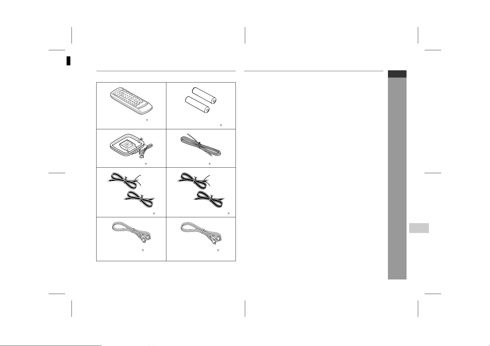
Accessories
Please confirm that the following accessories are included.
Contents
" General Information
Precautions . . . . . . . . . . . . . . . . . . . . . . . . . . . . . . . . . . . . . . . . . 3
Controls and ind ic a t or s . . . . . . . . . . . . . . . . . . . . . . . . . . . . .4 - 8
" Preparation for Use
System connect ions . . . . . . . . . . . . . . . . . . . . . . . . . . . . . . .9 - 13
Remote cont r ol . . . . . . . . . . . . . . . . . . . . . . . . . . . . . . . . . . . . . 14
Remote control 1 "AA" size battery (UM/SUM-3,
R6, HP-7 or similar) 2
Subwoofer connection . . . . . . . . . . . . . . . . . . . . . . . . . . . . . . . 15
Subwoofer con t r ol . . . . . . . . . . . . . . . . . . . . . . . . . . . . . . . . . . . 16
" Basic Operation
General contr ol . . . . . . . . . . . . . . . . . . . . . . . . . . . . . . . . . . . . . 17
Setting the cloc k . . . . . . . . . . . . . . . . . . . . . . . . . . . . . . . . . . . . 18
" Disc Playback
Video CD . . . . . . . . . . . . . . . . . . . . . . . . . . . . . . . . . . . . . . . . . . . 19
AM loop aerial 1 FM aerial 1
Red
Black
Grey
Black
Preparation for video CD playback . . . . . . . . . . . . . . . . . . . . . 20
Video CD playback . . . . . . . . . . . . . . . . . . . . . . . . . . . . . . .21 - 23
Advanced video CD playback . . . . . . . . . . . . . . . . . . . . . . .24 - 28
CD playback . . . . . . . . . . . . . . . . . . . . . . . . . . . . . . . . . . . . .29 - 31
" Radio
Listening to the r ad io . . . . . . . . . . . . . . . . . . . . . . . . . . . . . 32, 33
" Tape Playback
Listening to a cassette tape (TAPE 1 or TAPE 2) . . . . . . . 34, 35
Wire for front speaker 2 Wire for surround speaker 2
SHARP TINSZA092AWZZ (Z)
" Karaoke
Playing karaoke . . . . . . . . . . . . . . . . . . . . . . . . . . . . . . . . . . 36, 37
" Tape Recording
Recording on a cassette tape . . . . . . . . . . . . . . . . . . . . . . .38 - 40
General Information
4
" Advanced Features
Video cable 1 Subwoofer cable 1
(Yellow) (Black)
Note:
Only the above accessories are included.
Timer and sleep operation . . . . . . . . . . . . . . . . . . . . . . . . . 41 - 44
Enhancing your system . . . . . . . . . . . . . . . . . . . . . . . . . . . 45, 46
" References
Troubleshooti ng c ha r t . . . . . . . . . . . . . . . . . . . . . . . . . . . . .46 - 48
Maintenance . . . . . . . . . . . . . . . . . . . . . . . . . . . . . . . . . . . . . . . . 48
Specificati ons . . . . . . . . . . . . . . . . . . . . . . . . . . . . . . . . . . . 49, 50
E-2
04/3/22 CD-G10000V(Z)E1.fm
TINSZA092AWZZ
CD-G10000V
CP-G1000 0
ENGLISH
General Information
E-3
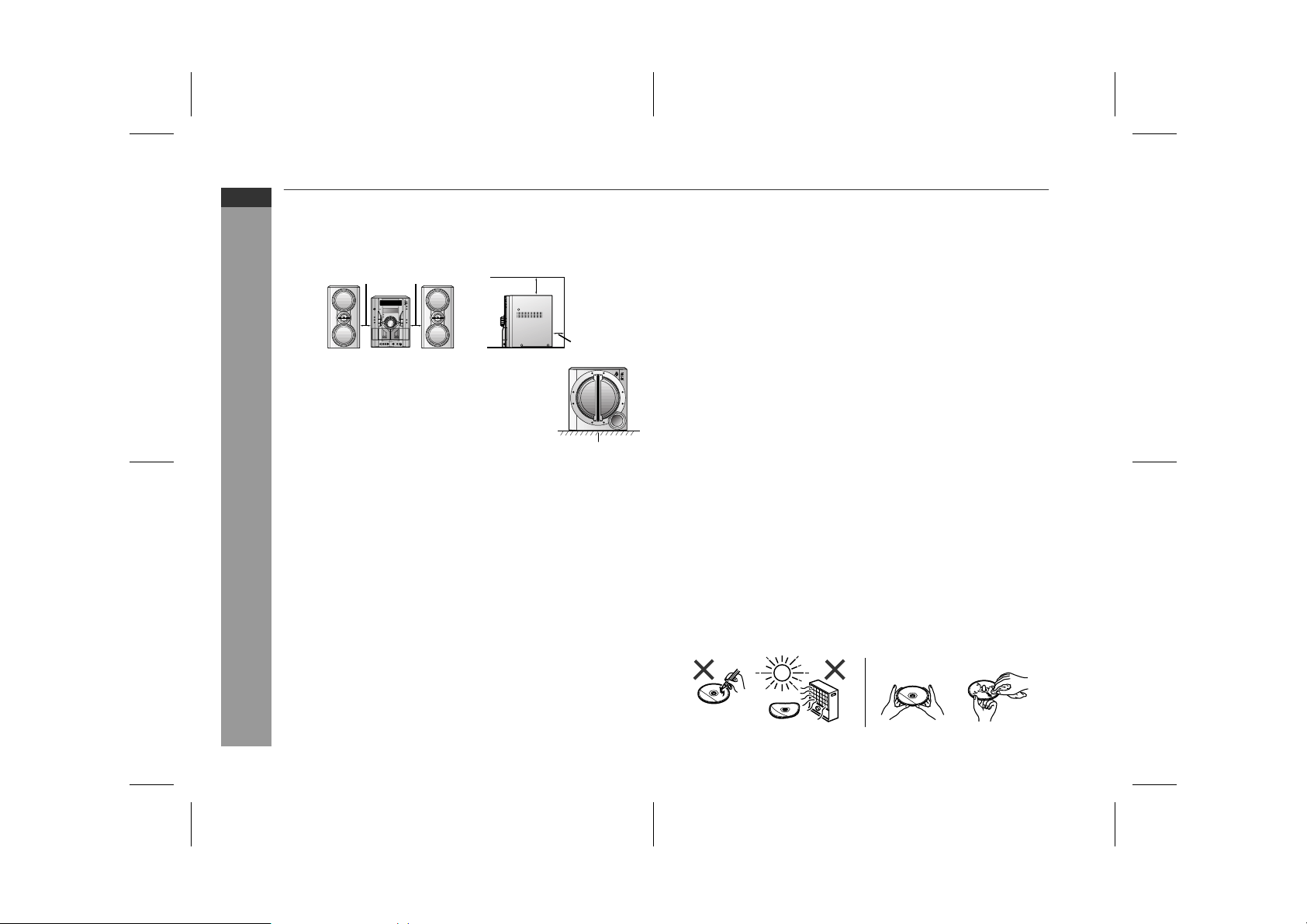
Precautions
" General
Please ensure that the system is posi tioned in a well ventilated
!
area and ensure that there is at least 10 c m (4") of free space
along the sides, top and back of the equipment.
10 cm (4") 10 cm (4")
Do not place active subwoofer system on
!
the same surface as main unit to prevent
sound interruption during playback.
Use the unit on a firm, level surface free from vibration.
!
Keep the unit away from direct sunlight, strong magnetic fields,
!
excessive dust, humidity and electronic/electrical equipment
(home computers, facsimiles, etc.) which generate electrical
noise.
Do not place anything on top of the unit and subwoofer.
!
Do not expose the system to moisture, to temperatures higher
!
than 60°C (140°F) or to extremely low temperatures.
If your system does not work properly, disconnect the AC power
!
lead from the wall socket. Plug the AC power lead back in, an d
then turn on your system.
In case of an electrical storm, unplug the system for safety.
!
Hold the AC power plug by the head when re moving it from the
!
wall socket, as pulling the lead can damage internal wires.
Do not remove the outer cover, as this may result in electric
!
shock. Refer internal service to your local SHARP servic e
facility.
The ventilation should not be impeded by covering the ventilation
!
openings with items, such as newspaper s, tablecloths, curtains,
etc.
No naked flame sources, such as lighted candles, should be
!
placed on the apparatus.
10 cm (4")
10 cm (4")
Floor
Attention should be drawn to the environmental aspects of bat-
!
tery disposal.
This system should only be used wi thin the range o f 5°C - 35°C
!
(41°F - 95°F).
Warning:
The voltage used must be the same as that specified on this unit.
Using this product with a higher voltage other than that which is
specified is dangerous and may result in a fire or other type of accident causing damage. SHARP will not be held responsible for any
damage resulting from use of this unit with a voltage other than that
which is specified.
" Volume control
The sound level at a given volume setting d epends on speaker effi ciency, location, and various ot her factors. It is advisable to avoi d
exposure to high volume levels. D o not turn the vol ume on to full at
switch on and listen to music at moderate levels.
" Care of compact discs
Compact discs are fairly resistant to damage, however mistracking
can occur due to an accumulation of dirt on the dis c surface. Follow
the guidelines below for maximum enjoyment from yo ur CD collection and player.
Do not write on either side of the disc, particularly the non-label
!
side from which signals are read. Do not mark this surface.
Keep your discs away from direct sunlight , heat, and excessive
!
moisture.
Always hold the CDs by the edges. Fingerprints, dirt, or water on
!
the CDs can cause noise or mistracking. If a CD is dir ty or does
not play properly, clean it with a soft, dry cloth, wiping straight out
from the centre, along the radius.
NO YES
Correct
04/3/22 CD-G10000V(Z)E1.fm
TINSZA092AWZZ
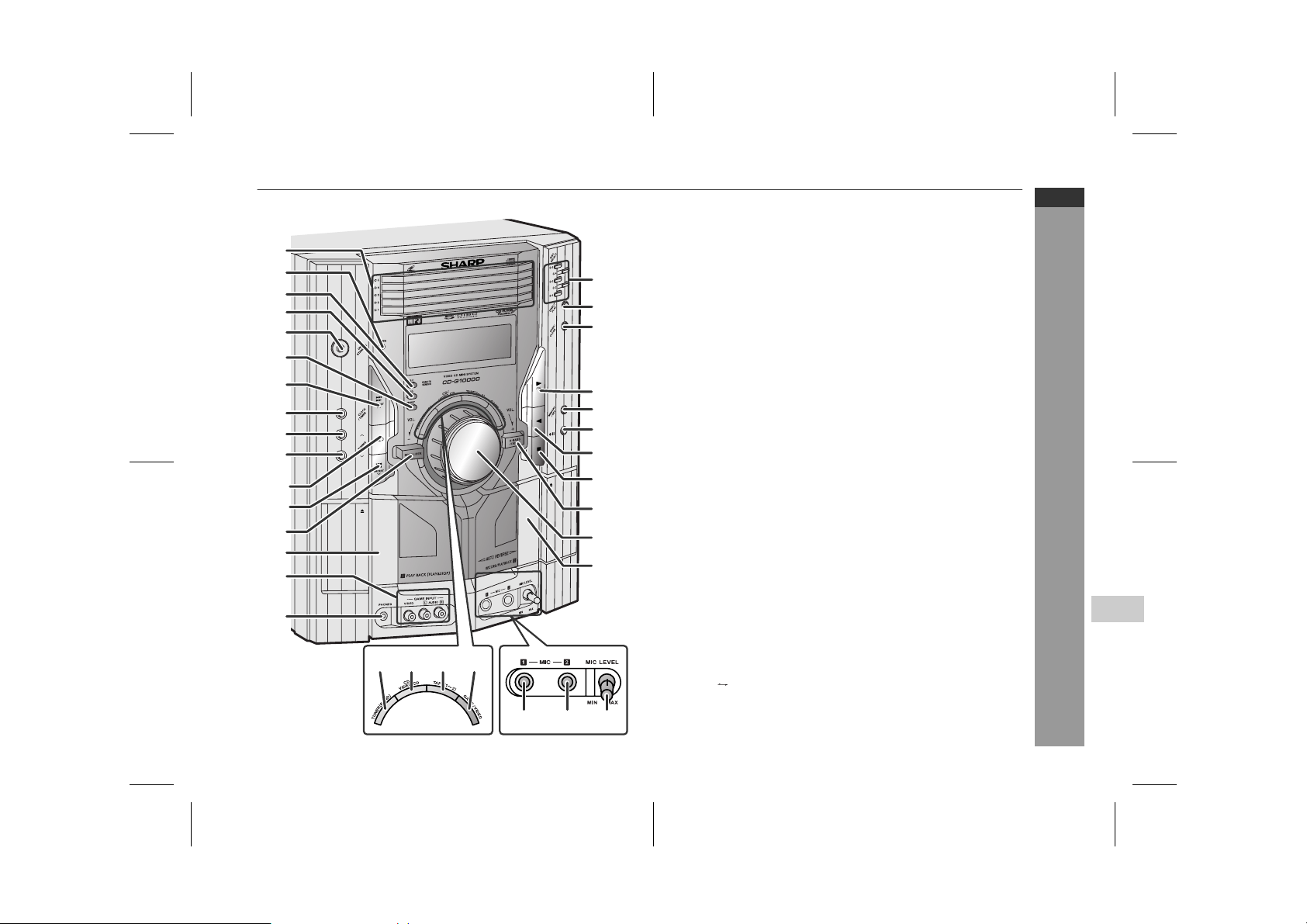
Controls and indic at ors
1
2
3
4
5
6
7
8
9
10
11
12
13
14
15
16
29 30 3128
17
18
19
20
21
22
23
24
25
26
27
32 33 34
" Front panel
1.Di sc Trays . . . . . . . . . . . . . . . . . . . . . . . . . . . . . . . . . . . . . . . 21
2.Timer Indicator . . . . . . . . . . . . . . . . . . . . . . . . . . . . . . . . . . . 42
3.Video CD Playback Control Button . . . . . . . . . . . . . . . . . . 23
4.Video CD On Screen Display On/O f f Bu t t on . . . . . . . . . . . 28
5.On/Stand-by Button . . . . . . . . . . . . . . . . . . . . . . . . . . . . . . . 17
6.Video CD Digest/Time Search Button . . . . . . . . . . . . . 26, 27
7.Video CD Skip or Next, CD/MP3 Disc Track Up or
Fast Forward, Tape 2 Fast Wind, Tuner Preset Up,
Time Up Button . . . . . . . . . . . . . . . . . . . . . . . . . 18, 22, 33, 35
8.Clock/Timer Button . . . . . . . . . . . . . . . . . . . . . . . . . 18, 41, 44
9.Tuning Up Button . . . . . . . . . . . . . . . . . . . . . . . . . . . . . . . . . 32
10.Tuning Down Button . . . . . . . . . . . . . . . . . . . . . . . . . . . . . . 32
11.Tape 2 Reverse Mode Select Button . . . . . . . . . . . . . . . . . 35
12.Video CD Skip or Previous, CD/MP3 Disc Track Down or
Fast Reverse, Tape 2 Fast Wind, Tuner Preset Down,
Time Down Button . . . . . . . . . . . . . . . . . . . . . . . 18, 22, 33, 35
13.Equaliser Mode Select Button . . . . . . . . . . . . . . . . . . . . . . 17
14.Tape 1 Cassette Compartment . . . . . . . . . . . . . . . . . . . . . . 34
15.Game/Video Input Sockets . . . . . . . . . . . . . . . . . . . . . . . . . 45
16.Headphone Socket . . . . . . . . . . . . . . . . . . . . . . . . . . . . . . . . 46
17.Disc Number Select Buttons . . . . . . . . . . . . . . . . . . . . . . . . 21
18.Disc Direct Play Button . . . . . . . . . . . . . . . . . . . . . . . . . . . . 24
19.Disc Tray Open/Close Button . . . . . . . . . . . . . . . . . . . . . . . 21
20.Video CD Play or Repeat or Select or Resume,
CD/MP3 Disc Play or Repeat, Tape 1 Play,
Tape 2 Forward Play Button . . . . . . . . . . . . 21, 27, 29, 34, 35
21.Memory/Set Button . . . . . . . . . . . . . . . . . . . 18, 30, 33, 41, 44
22.Tape 2 Record Pause Button . . . . . . . . . . . . . . . . . . . . 39, 40
23.Tape 2 Reverse Play Button . . . . . . . . . . . . . . . . . . . . . . . . 35
24.V id eo CD Stop or Retu rn, CD/MP3 Disc/
Tape Stop Button . . . . . . . . . . . . . . . . . . . . . . . . . . . 22, 23, 35
25.Extra Bass/Demo Mode Button . . . . . . . . . . . . . . . . . . 16, 17
26.Volume Control . . . . . . . . . . . . . . . . . . . . . . . . . . . . . . . . . . 17
27.Tape 2 Cassette Compartment . . . . . . . . . . . . . . . . . . . . . . 35
28.Tuner (Band) Button . . . . . . . . . . . . . . . . . . . . . . . . . . . . . . 32
29.Video CD/CD/MP3 Disc Button . . . . . . . . . . . . . . . . . . . . . . 21
30.Tape (1 2) Button . . . . . . . . . . . . . . . . . . . . . . . . . . . . 34, 35
31.Game/Video Button . . . . . . . . . . . . . . . . . . . . . . . . . . . . . . . 45
32.Microphone Socket 1 . . . . . . . . . . . . . . . . . . . . . . . . . . . . . . 36
33.Microphone Socket 2 . . . . . . . . . . . . . . . . . . . . . . . . . . . . . . 36
34.Microphone Level Control . . . . . . . . . . . . . . . . . . . . . . . . . . 36
Reference page
CD-G10000V
CP-G10000
ENGLISH
General Information
E-4
4
04/3/22 CD-G10000V(Z)E1.fm
TINSZA092AWZZ
CD-G10000V
CP-G1000 0
ENGLISH
General Information
Controls and indicators (continued)
1110
12 13
976 8321 4 5
1614 15
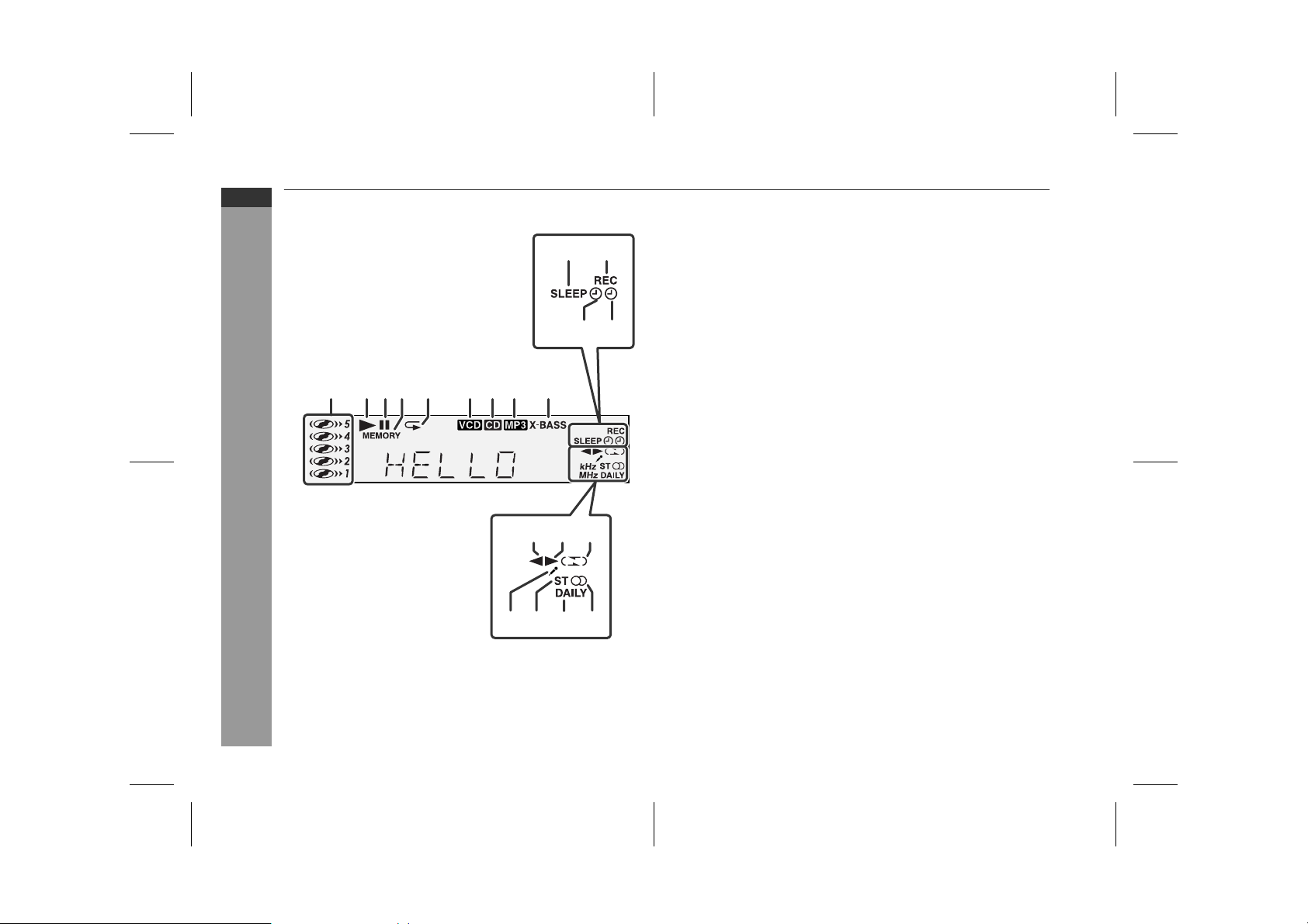
" Display
Reference page
1.Disc Number Indicat o rs . . . . . . . . . . . . . . . . . . . . . . . . . . . . 24
2.Disc Play Indicat or . . . . . . . . . . . . . . . . . . . . . . . . . . . . . . . . 22
3.Disc Pause Indic a tor . . . . . . . . . . . . . . . . . . . . . . . . . . . . . . 2 2
4.Memory Indicator . . . . . . . . . . . . . . . . . . . . . . . . . . . . . . . . . 30
5.Disc Repeat Play Indicator . . . . . . . . . . . . . . . . . . . . . . . . . 2 9
6.Video CD Indicator . . . . . . . . . . . . . . . . . . . . . . . . . . . . . . . . 24
7.CD Indicator . . . . . . . . . . . . . . . . . . . . . . . . . . . . . . . . . . . . . 29
8.MP3 Disc Indicat or . . . . . . . . . . . . . . . . . . . . . . . . . . . . . . . . 31
9.Extra Bass Indicator . . . . . . . . . . . . . . . . . . . . . . . . . . . . . . . 17
10.Sleep Indicator . . . . . . . . . . . . . . . . . . . . . . . . . . . . . . . . . . . 44
11.Tape 2 Record Indic a t or . . . . . . . . . . . . . . . . . . . . . . . . . . . 39
12.Timer Play Indic ator . . . . . . . . . . . . . . . . . . . . . . . . . . . . . . . 42
13.Timer Recording Indicator . . . . . . . . . . . . . . . . . . . . . . . . . . 42
14.Tape 2 Reverse Play Indicator . . . . . . . . . . . . . . . . . . . . . . 35
15.Tape 1 Play or Tape 2 Forward Play Indicator . . . . . . . 34, 35
16.Tape Reverse Mode Indicator . . . . . . . . . . . . . . . . . . . . . . . 35
17.Karaoke Mode Indic ator . . . . . . . . . . . . . . . . . . . . . . . . . . . . 37
18.FM Stereo Mode Indicator . . . . . . . . . . . . . . . . . . . . . . . . . . 32
19.Daily Timer Indic a t or . . . . . . . . . . . . . . . . . . . . . . . . . . . . . . 42
20.FM Stereo Receiving Indicator . . . . . . . . . . . . . . . . . . . . . . 32
E-5
1918 2017
04/3/22 CD-G10000V(Z)E1.fm
TINSZA092AWZZ
CD-G10000V
CP-G10000
ENGLISH
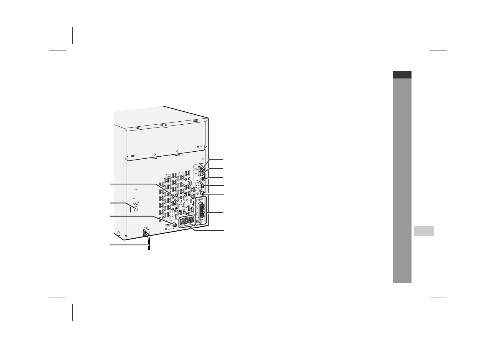
" Rear panel
1.Cooling Fan . . . . . . . . . . . . . . . . . . . . . . . . . . . . . . . . . . . . . 12
2.AC Voltage Selector . . . . . . . . . . . . . . . . . . . . . . . . . . . . . . . 12
3.Subwoofer Pre-output Socket . . . . . . . . . . . . . . . . . . . . . . 15
4.AC Power Lead . . . . . . . . . . . . . . . . . . . . . . . . . . . . . . . . . 9, 12
5.FM 75 Ohm Aerial Terminal . . . . . . . . . . . . . . . . . . . . . . . 9, 10
6.FM Aerial Earth Terminal . . . . . . . . . . . . . . . . . . . . . . . . . 9, 10
7.AM Loop Aerial Socket . . . . . . . . . . . . . . . . . . . . . . . . . . 9, 10
8.Span Selector Switch . . . . . . . . . . . . . . . . . . . . . . . . . . . . . 13
9.Video Output Socket . . . . . . . . . . . . . . . . . . . . . . . . . . . . . . 11
10.Front Speaker Terminals . . . . . . . . . . . . . . . . . . . . . . . . . 9, 10
11.Surround Speaker Terminals . . . . . . . . . . . . . . . . . . . . . 9, 10
Reference page
5
6
7
1
8
9
2
3
10
General Information
11
4
4
E-6
04/3/22 CD-G10000V(Z)E1.fm
TINSZA092AWZZ
CD-G10000V
CP-G1000 0
ENGLISH
General Information
Controls and indicators (continued)
1
1
1
2
3
2
4
5
6
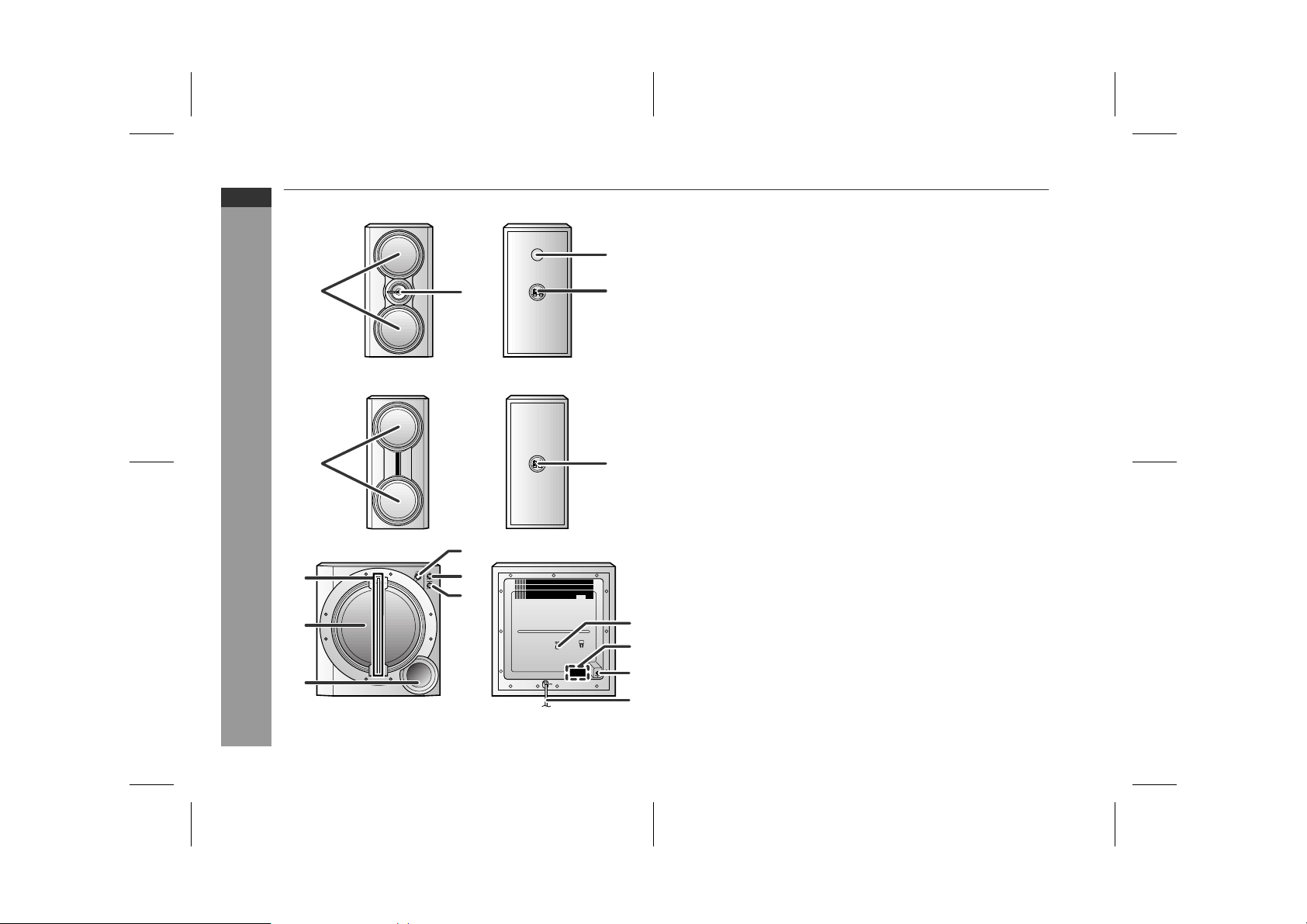
" Front speaker
1.Woofers
2.Tweeter
3
4
3.Bass Refl ex Duct
4.Speaker Terminals
" Surround speaker
1.Full-range Speakers
2.Speaker Terminals
2
" Active subwoofer
1.Power Indicator . . . . . . . . . . . . . . . . . . . . . . . . . . . . . . . . . . 16
2.Subwoofer
3.Bass Refl ex Duct
7
8
9
10
4.Power Switch . . . . . . . . . . . . . . . . . . . . . . . . . . . . . . . . . . . . 16
5.Volume Control . . . . . . . . . . . . . . . . . . . . . . . . . . . . . . . . . . . 16
6.Crossover Frequen c y Control . . . . . . . . . . . . . . . . . . . . . . . 16
7.AC Voltage Selector . . . . . . . . . . . . . . . . . . . . . . . . . . . . . . . 15
8.Cooling Fan
9.Subwoofer Input Socket . . . . . . . . . . . . . . . . . . . . . . . . . . . 15
10.AC Power Lead . . . . . . . . . . . . . . . . . . . . . . . . . . . . . . . . . . . 15
Reference page
E-7
04/3/22 CD-G10000V(Z)E1.fm
TINSZA092AWZZ
CD-G10000V
CP-G10000
ENGLISH
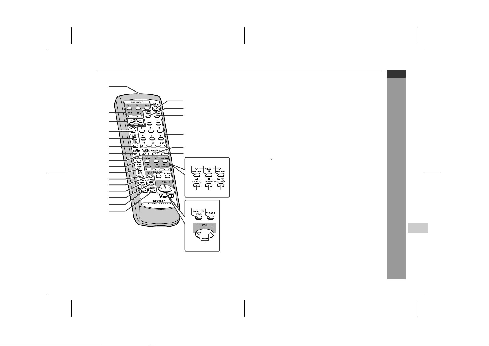
" Remote control
Reference page
General Information
4
10
11
12
13
14
15
16
1
17
2
18
19
3
4
5
6
7
8
9
20
21
22
26
24 2523
27 28
29 30
31
1.Remote Control Transmitter . . . . . . . . . . . . . . . . . . . . . . . . 14
2.Disc Number Select Buttons . . . . . . . . . . . . . . . . . . . . . . . . 21
3.Echo Level Up and Down Buttons . . . . . . . . . . . . . . . . . . . 36
4.Karaoke Mode Button . . . . . . . . . . . . . . . . . . . . . . . . . . . . . 37
5.Video CD Auto/On Button . . . . . . . . . . . . . . . . . . . . . . . . . . 28
6.Video CD Playback Control Auto/Off Button . . . . . . . . . . . 23
7.Video CD On Screen Display On/O f f Bu t t on . . . . . . . . . . . 28
8.Disc Clear/Dimmer Button . . . . . . . . . . . . . . . . . . . . . . 17, 30
9.Video CD Digest/Time Search Button . . . . . . . . . . . . . 26, 27
10.Video CD Bookmark Button . . . . . . . . . . . . . . . . . . . . . . . . 25
11.PAL/NTSC Select Button . . . . . . . . . . . . . . . . . . . . . . . . . . . 20
12.Tape 2 Record Pause Button . . . . . . . . . . . . . . . . . . . . 39, 40
13.Video CD/CD/MP3 Disc Button . . . . . . . . . . . . . . . . . . . . . . 21
14.Tuner (Band) Button . . . . . . . . . . . . . . . . . . . . . . . . . . . . . . 32
15.Tape (1 2) Button . . . . . . . . . . . . . . . . . . . . . . . . . . . . 34, 35
16.Game/Video Button . . . . . . . . . . . . . . . . . . . . . . . . . . . . . . . 45
17.On/Stand-by Button . . . . . . . . . . . . . . . . . . . . . . . . . . . . . . . 17
18.Clock/Timer Button . . . . . . . . . . . . . . . . . . . . . . . . . 18, 41, 44
19.MP3 Disc Display Button . . . . . . . . . . . . . . . . . . . . . . . . . . . 31
20.Disc Direct Search Buttons . . . . . . . . . . . . . . . . . . . . . . . . . 24
21.Memory/Set Button . . . . . . . . . . . . . . . . . . . 18, 30, 33, 41, 44
22.Disc Random Button . . . . . . . . . . . . . . . . . . . . . . . . . . . . . . 29
23.Video CD Skip or Previous, CD/MP3 Disc Track Down or
Fast Reverse, Tape 2 Fast Wind, Tuner Preset Down,
Time Down Button . . . . . . . . . . . . . . . . . . . . . . . 18, 22, 33, 35
24.Disc Pause Button . . . . . . . . . . . . . . . . . . . . . . . . . . . . . . . . 22
25.Video CD Skip or Next, CD/MP3 Disc Track Up or
Fast Forward, Tape 2 Fast Wind, Tuner Preset Up,
Time Up Button . . . . . . . . . . . . . . . . . . . . . . . . . 18, 22, 33, 35
26.Tape 2 Reverse Play Button . . . . . . . . . . . . . . . . . . . . . . . . 35
27.V id eo CD Stop or Retu rn, CD/MP3 Disc/
Tape Stop Button . . . . . . . . . . . . . . . . . . . . . . . . . . . 22, 23, 35
28.Video CD Play or Repeat or Select or Resume,
CD/MP3 Disc Play or Repeat, Tape 1 Play,
Tape 2 Forward Play Button . . . . . . . . . . . . 21, 27, 29, 34, 35
29.Equaliser Mode Select Button . . . . . . . . . . . . . . . . . . . . . . 17
30.Extra Bass Button . . . . . . . . . . . . . . . . . . . . . . . . . . . . . . . . 17
31.Volume Up and Down Buttons . . . . . . . . . . . . . . . . . . . . . . 17
04/3/22 CD-G10000V(Z)E1.fm
E-8
TINSZA092AWZZ
CD-G10000V
CP-G1000 0
ENGLISH
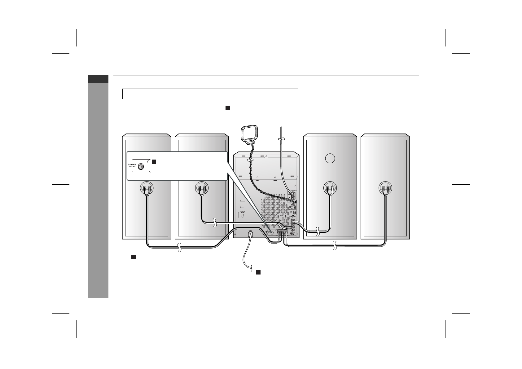
System connections
Make sure to unplug the AC power lead before making any connections.
Aerial connection (see page 10)
Preparation for Use
Surround speaker
(right)
Front speaker
(right)
Subwoofer connection
(see page 15)
Speaker connection (see page 10)
AM loop aerial
To a wall socket
FM aerial
Front speaker
(left)
AC power connection (see page 12)
Surround speaker
(left)
E-9
04/3/22 CD-G10000V(Z)E1.fm
TINSZA092AWZZ
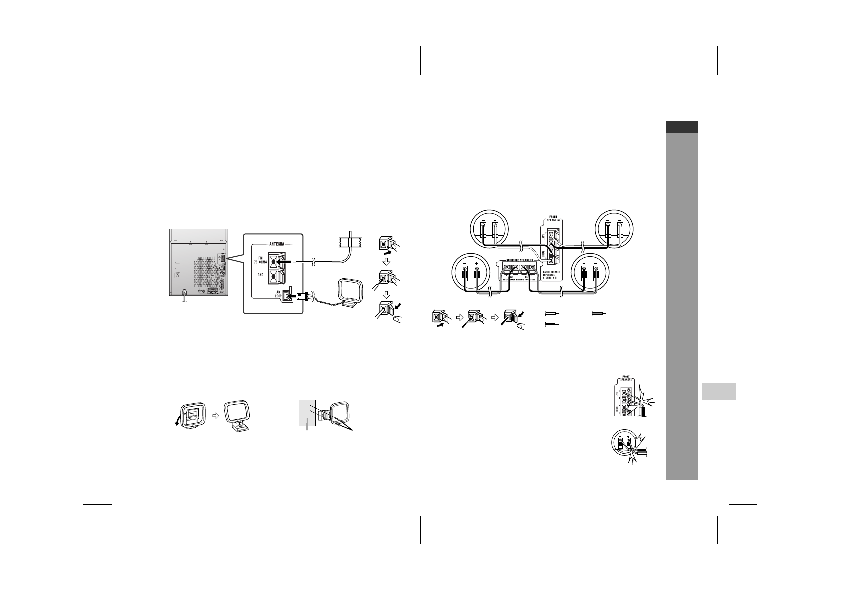
" Aerial connection
Supplied FM aerial:
Connect the FM aerial wire to the FM 75 OHMS terminal and position the FM aerial wire in the direction where the strongest signal
can be received.
Supplied AM loop aerial:
Connect the AM loop aerial to t he AM LOOP socket. Position the
AM loop aerial for optimum reception. Place the AM loop aerial on a
shelf, etc., or attach it to a stand or a wall with screws (not supplied).
Note:
Placing the aerial on the unit or near the AC power lead may cause
noise pickup. Place the aerial away from the unit for better reception.
Installing the AM loop aerial:
< Assembling > < Attaching to the wall >
Wall Screws (not supplied)
" Speaker connection
Front speakers:
Connect the black wire to the FRONT SPEAKERS (-) terminal, and
the red wire to the F R ONT SPEAKERS (+) term in al.
Surround speakers:
Connect the black wire to the SURROUND SPEAKERS (-) terminal,
and the grey wire to the SURROUND SPEAKERS (+) terminal.
Front speaker (right)
Surround speaker (right) Surround speaker (left)
Caution:
Connect the speaker wires to the speakers first, then to the unit.
!
Never mistake the FRONT SPEAKERS and the SURROUND-
!
SPEAKERS terminals. The unit or the speakers may be damaged.
If you use other speakers with impedance lower
!
than that specified, the unit may be damaged. Front
speakers: 8 ohms Surround speakers: 16 ohms
Do not mistake the right and the left channels. The
!
right speaker is the one on the right side when you
face the unit.
Do not let the bare speaker wires touch each
!
other.
Do not allow any objects to fall into or to be placed
!
in the bass reflex ducts.
Do not stand or sit on the speakers. You may be in-
!
jured.
Front speaker (left)
Red
Black
Grey
Incorrect
Incorrect
CD-G10000V
CP-G10000
ENGLISH
Preparation for Use
4
04/3/22 CD-G10000V(Z)E1.fm
E-10
TINSZA092AWZZ
CD-G10000V
CP-G1000 0
ENGLISH
System connections (continued)
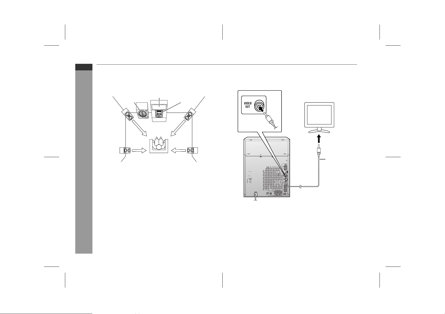
! Placing the speaker system
To enjoy the surround effect, we recommend t hat you place each
speaker as shown to the below.
TVActive
subwoofer
Main unit
! TV/monitor connection
If the TV/monitor has a video input, connect it to the VIDEO OUT
socket on the rear of the unit.
E-11
Front
speaker
(left)
Surround
speaker
(left)
Notes:
The speakers are magnetically shielded.
"
Therefore, they do not affect the display even you use them near
the TV. However, some colour variation may occur, depending on
the type of TV used.
Preparation for Use
If colour variation occurs...
Turn off the TV (from the power switch).
After 15 - 30 minutes, turn the TV on again.
If the colour variation is still present...
Move the speakers further away from the TV.
If any kind of magnet or an electromagnet is placed too close to
"
the TV and the system, irregular colours may appear on the TV
screen.
Note:
The speaker grilles are not removable.
Front
speaker
(right)
Surround
speaker
(right)
TV
To video
input socket
Video cable
Note:
If the TV/monitor does not have a video input, the VIDEO OUT
socket on the unit should be connected to a VCR with a video input,
which in turn should be connected to the TV/monitor through the TV
ANTENNA/CABLE input. (Be sure to turn on the VCR, and set the
VCR's input mode to "auxiliary".)
04/3/22 CD-G10000V(Z)E2.fm
TINSZA092AWZZ

1
2
! Setting the AC voltage selector
Check the setting of the AC voltage selector located on the rear
panel before plugging the unit into a wall socket. If necessary, adjust
the selector to correspond to the AC power voltage used in your
area.
! AC power connection
After checking all the connections have been made correctly, plug
the AC power lead of this unit into the wall socket. If you plug the
unit first, the unit will enter the demonstration mode (see page 13).
Notes:
The unit will start the tape initialisation when plugged in to the AC
"
socket. During this process, initialising sound will be heard and
the unit cannot be turned on. Wait until the process is finished.
Unplug the AC power lead from the wall socket if the unit will not
"
be in use for a prolonged period of time.
AC Plug Adaptor
In areas (or countries) where a wall socket as shown in illustration
is used, connect the unit using the AC pl ug adaptor supplied with
the unit, as illustrated. The AC plug adaptor is not included in areas
where the wall socket and AC power plug can be directly connected
(see illustration ).
Cooling fan:
This product is equipped with a cooling fan inside, which begins to
run once the power is on for better heat radiation.
CD-G10000V
CP-G10000
ENGLISH
Preparation for Use
Turn the selector with a screwdriver until the appropriate voltage number appears in the window (110 V, 127 V, 220 V or 230
V - 240 V AC).
04/3/22 CD-G10000V(Z)E2.fm
4
E-12
TINSZA092AWZZ
CD-G10000V
CP-G1000 0
ENGLISH
Preparation for Use
E-13
System connections (continued)
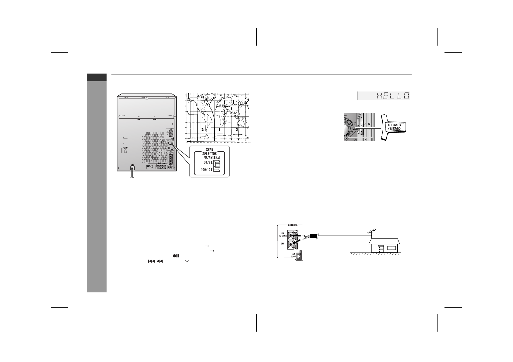
! Setting the FM/AM span selector
The International Telecommunication Union (ITU) has established
that member countries should maintain either a 100 kHz or a 50 kHz
interval between broadcasting f requencies of FM stations and 10
kHz or 9 kHz for AM station. The illustration shows the 50/9 kHz
zones (regions 1 and 3), and the 100/10 kHz zone (region 2).
Before using the unit, set the SPAN SELECTOR switch (on the rear
panel) to the interval (span) of your area.
To change the tuning zone:
1 Press the ON/STAND-BY button to enter the stand-by mode.
2 Set the SPAN SELECTOR switch (on the rear panel) as follows.
For 50 kHz FM interval (9 kHz in AM) 50/9
"
For 100 kHz FM interval (10 kHz in AM) 100/10
"
3 Whilst pressing down the button and the X-BASS/DEMO but-
ton, press the PRESET button until "CLEAR AL" appears.
Caution:
This operation will erase all data stored in memory including clock,
timer settings, tuner preset, and CD programme.
! Demonstration mode
The first time the unit is plugged in, the
unit will enter the demonstration mode.
You will see words scroll.
To cancel the demonstration
mode:
When the unit is in the power standby mode (demonstration mode),
press the X-BASS/DEMO button.
The demonstration mode will be
cancelled and the display will disappear.
To return to the demonstration mode:
When the unit is in the power stand-by mode, press the X-BASS/
DEMO button again.
Note:
When the power is on, the X-BASS/DEMO button can be used to select the extra bass mode.
! External FM aerial
Use an external FM aerial if you require better reception.
Consult your dealer.
External
FM aerial
75 ohm
coaxial cable
Note:
When an external FM aerial is used, disconnect the supplied FM
aerial wire.
04/3/22 CD-G10000V(Z)E2.fm
TINSZA092AWZZ
Remote control
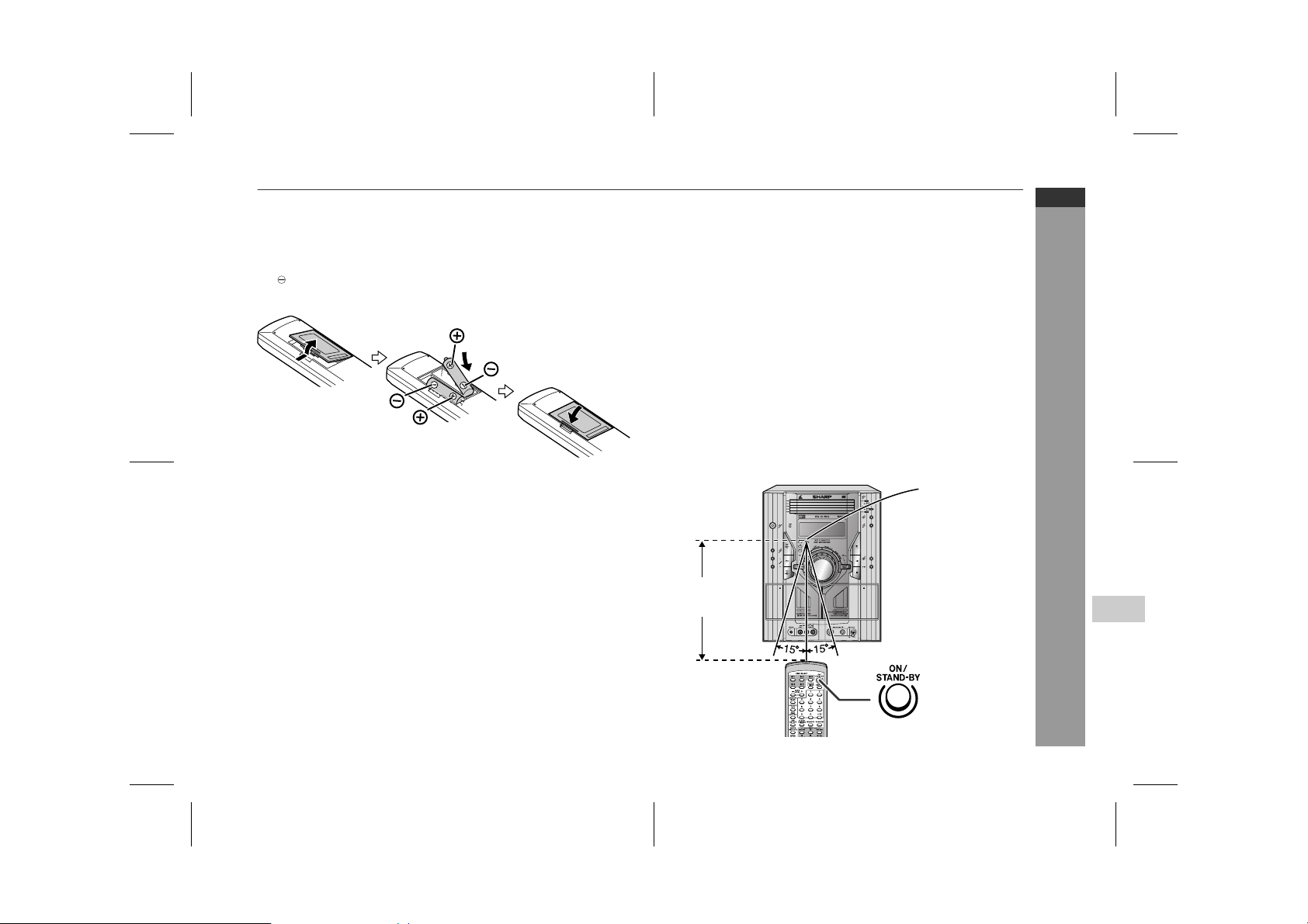
! Battery installation
1 Remove the battery cover.
2 Insert the supplied batteries according to the direction indi-
cated in the battery compartment.
When inserting or removing the batteries, push them towards the
battery terminals.
3 Replace the cover.
Precautions for battery use:
Replace all old batteries with new ones at the same time.
"
Do not mix old and new batteries.
"
Remove the batteries if the unit is not to be used for long per iod s
"
of time. This will prevent potential damage due to battery leakage.
Notes concerning use:
Replace the batteries if the operating distance is reduced or if the
"
operation becomes erratic. Purchase 2 "AA" size batteries (UM/
SUM-3, R6, HP-7 or similar).
Periodically clean the transmitter on the remote control and the
"
sensor on the unit with a soft cloth.
Exposing the sensor on the unit to strong light may i nterfere with
"
operation. Change the lighting or the direction of the unit.
Keep the remote control away from moisture, heat, shock, and
"
vibrations.
! Test of the remote control
Check the remote control af ter checking all the connections (see
pages 9 - 12).
Point the remote control directly at the remote sensor on the unit.
The remote control can be used within the range shown below:
Press the ON/STAND-BY button. Does the power turn on? Now,
you can enjoy music.
Remote sensor
CD-G10000V
CP-G10000
ENGLISH
Preparation for Use
Caution:
Do not use rechargeable batteries (nickel-cadmium battery, etc.).
"
Installing the batteries i ncorrectly may ca use t he unit t o mal func-
"
tion.
0.2 m - 6 m
(8" - 20')
04/3/22 CD-G10000V(Z)E2.fm
4
E-14
TINSZA092AWZZ
CD-G10000V
CP-G1000 0
ENGLISH
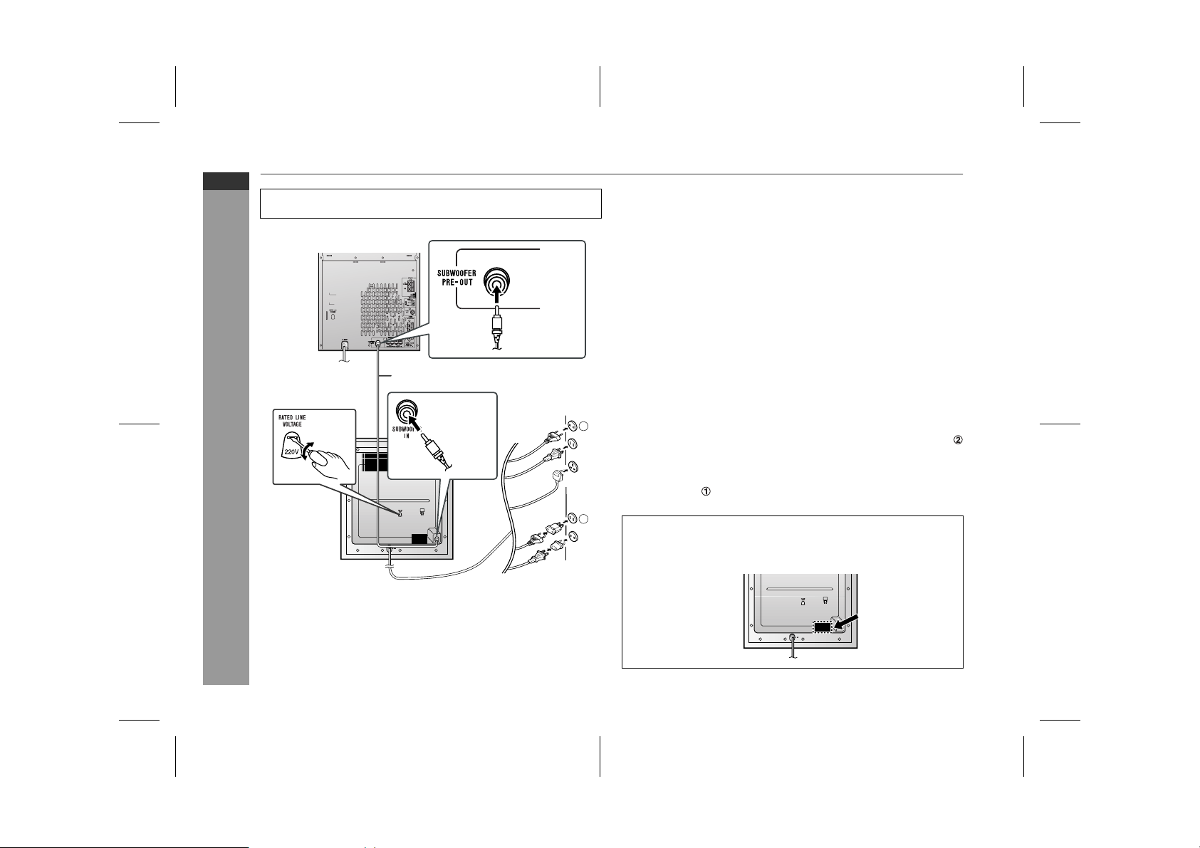
Subwoofer connection
Make sure to unplug the AC power lead of main unit before any
connections.
Main unit
To subwoofer
output socket
! Setting the AC voltage selector
Check the setting of the AC voltage selector located on the rear
panel before plugging the unit into a wall socket. If necessary, adjust
the selector to correspond to the AC power voltage used in your
area.
Turn the selector with a screwdriver until the appropriate voltage number appears in the window (110 V, 127 V, 220 V or 230
V - 240 V AC).
! Connecting the AC power lead
After checking all the connections have been made correctly, plug
the AC power lead of this unit into the wall socket.
E-15
Subwoofer cable
To subwoofer
input socket
Preparation for Use
Active subwoofer
! Connecting the subwoofer
Use the subwoofer cable to connect the SUBWOOFER PRE-OUT
socket on the main unit and the SUBWOOFER IN socket on the
active subwoofer.
Note:
Unplug the AC power lead from the wall socket if the unit will not be
in use for a prolonged period of time.
1
AC Plug Adaptor
In areas (or countries) where a wall socket as shown in illustration
is used, connect the unit using the AC plug adaptor supplied with
the unit, as illustrated. The AC plug adaptor is not included in areas
where the wall socket and AC power plug can be directly connected
(see illustration ).
2
Cooling fan:
This product is equipped with a cooling fan inside, which begins to
run once the power is on for better heat radiation.
04/3/22 CD-G10000V(Z)E2.fm
TINSZA092AWZZ
 Loading...