

Sharp AR M550N - B/W Laser - Copier,AR-M550N,AR-M550U,AR-M620N,AR-M620U,AR-M700N,AR-M700U Installation Manual
CONTENTS
Parts marked with “ ” are important for maintaining the safety of the machine. Be sure to replace these parts
with the replacement parts specified to maintain the safety and performance of the machine.
SHARP CORPORATION
This document has been published to be used
for after sales service only.
The contents are subject to change without notice.
INSTALLATION MANUAL
CODE : 00ZAR700//I1E
DIGITAL LASER COPIER/PRINTER
DIGITAL MULTIFUNCTIONAL SYSTEM
AR-M550N/M550U
AR-M620N/M620U
MODEL
AR-M700N/M700U
[ 1 ] AR-M550/M620 UNPACKING AND INSTALLATION . . . . . . . . . . 1 - 1
[ 2 ] AR-LC6 UNPACKING AND INSTALLATION . . . . . . . . . . . . . . . . 2 - 1
[ 3 ] AR-CF2 UNPACKING AND INSTALLATION . . . . . . . . . . . . . . . . 3 - 1
[ 4 ] AR-F15/F16 UNPACKING AND INSTALLATION . . . . . . . . . . . . . 4 - 1
[ 5 ] AR-PN4 UNPACKING AND INSTALLATION . . . . . . . . . . . . . . . . 5 - 1
[ 6 ] AR-P19 INSTALLATION . . . . . . . . . . . . . . . . . . . . . . . . . . . . . . . . 6 - 1
[ 7 ] AR-FR11 INSTALLATION . . . . . . . . . . . . . . . . . . . . . . . . . . . . . . . 7 - 1
[ 8 ] AR-PK5 INSTALLATION. . . . . . . . . . . . . . . . . . . . . . . . . . . . . . . . 8 - 1
[ 9 ] AR-NS3 INSTALLATION. . . . . . . . . . . . . . . . . . . . . . . . . . . . . . . . 9 - 1
[10] AR-FX8/AR-MM9 INSTALLATION . . . . . . . . . . . . . . . . . . . . . . . 10 - 1
[11] MECHANICAL COUNTER INSTALLATION . . . . . . . . . . . . . . . . . 11-1
[12] DRY HEATER INSTALLATION. . . . . . . . . . . . . . . . . . . . . . . . . . . 12-1
1
1
1
1
2
2
AR-M550/M620/M700 INSTALLATION MANUAL (AR-M550/M620/M700) 1 - 1
[1] AR-M550/M620/M700
UNPACKING AND INSTALLATION
1. Installing (use) conditions
Before installing the machine, check that the following installing (use)
conditions are satisfied.
If the installing (use) conditions are not satisfied, the machine may not
display full performances, resulting in troubles. It may also cause
safety problems. Therefore, be sure to arrange the installing (use) conditions before setting up the machine.
A. Bringing space
For installation of a large size machine, be sure to check that the door
size is great enough before bringing in.
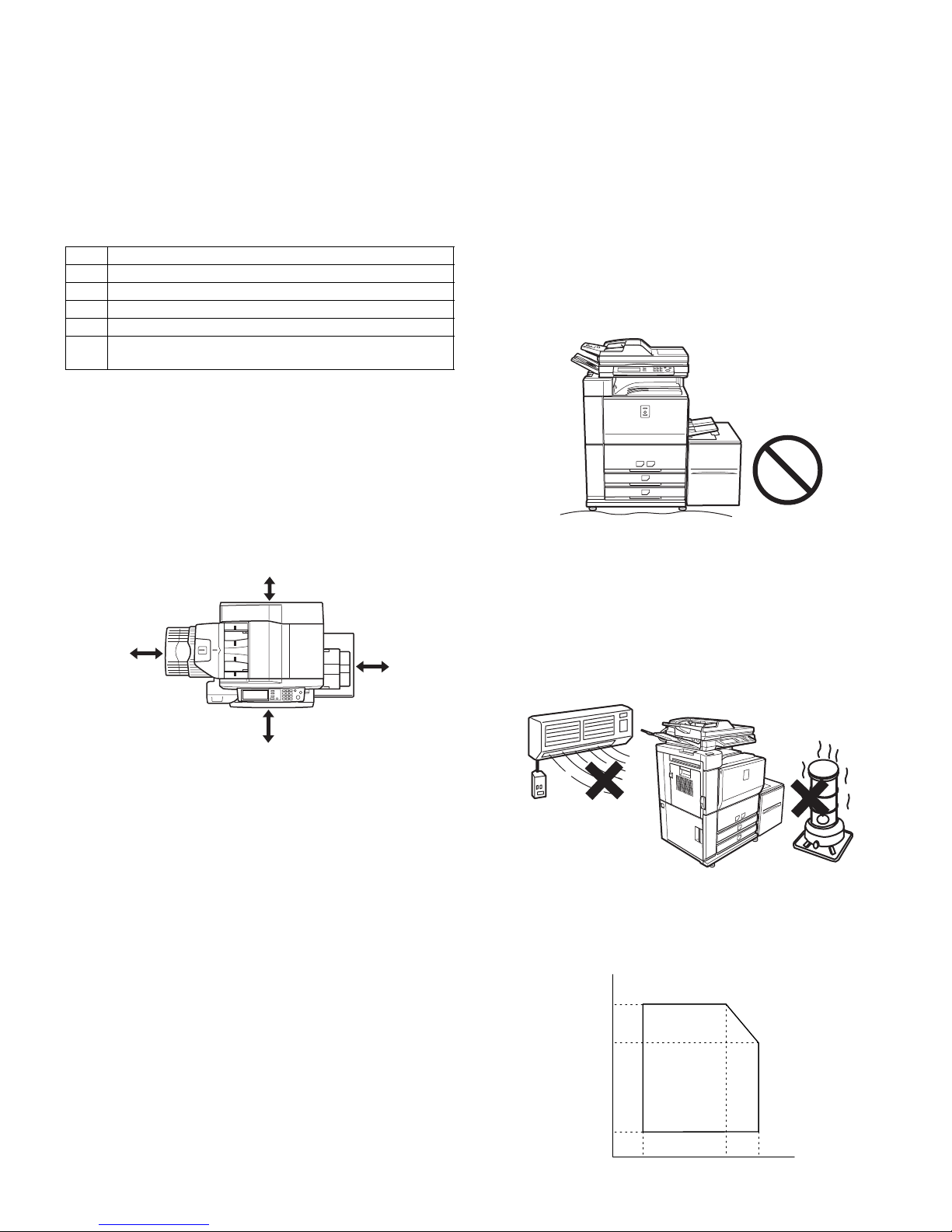
B. Installing space
The following space must be provided around the machine in order to
assure machine performances and proper operations.
If any option is installed, provide the additional space for installing it.
Especially the space at the rear of the machine must be provided suffi-
ciently. If not, the machine cannot exhibit functions against heat and
dust, causing some troubles.
C. Power source
(Capacity, voltage, frequency, safety, plug)
If the power specifications are not satisfied, the machine cannot exhibit
full performances and may cause safety trouble.
Strictly observe the following specifications.
(1) Power capacity
Check that the following power capacity is satisfied. If not, additionally
provide a power source.
Current capacity
Japan: 20A or more
100V: 20A or more
200V: 10A or more
(2) Power voltage
Measure the voltage during copying to check that the voltage is in the
range of the specified voltage ±10%.
If the voltage is outside the specified range, use thicker lead wires to
reduce impedance.
(An electrical work is required.)
Use of a step-up transformer is also available. In this case, the capac-
ity must be great enough for the max. power consumption of the
machine.
(3) Power frequency, waveform
The frequency must be within the range of the specified frequency
±2%. If power waveform is deformed, a trouble may occur.
(4) Safety
Be sure to properly ground the machine.
(5) Power plug
Check the form of the power plug. If the shape does not match, do not
use it.
D. Floor strength and level
This machine is considerably heavy and becomes heavier with an
option installed.
The floor must be strong enough for assuring safety, and the machine
must be installed horizontally.
If not, toner concentration control is not properly performed, resulting in
degraded copy quality and distorted images.
E. Direct rays of the sun, dust, temperature,
humidity, gasses, chemicals, vibration
(1) Temperature and humidity
This machine is designed to perform properly under the specified temperature and humidity. If the temperature and humidity exceeds the
specified range, the machine may not operate properly and or cause
equipment failure.
Especially when the humidity is too high, paper absorbs humidity to
cause a paper jam or dirty copy.
(Do not install the machine near a stove, a humidifier, or an air conditioner.)
Do not install the machine near a heater, a cooler, or a humidifier.
Dew may be formed inside the machine to cause a trouble. Use
enough care for ventilation.
No. Content
1 Bringing space
2 Installing space
3 Power source (Capacity, fluctuation, safety)
4 Floor strength
5 Direct rays of the sun, dust, temperature, humidity, gases,
chemicals
31.5"
(80cm)
23.6"
(60cm)
23.6"
(60cm)
11.8"
(30cm)
Humidity (RH)
85%
60%
20%
10˚C 30˚C 35˚C Temperature
AR-M550/M620/M700 INSTALLATION MANUAL (AR-M550/M620/M700) 1 - 2
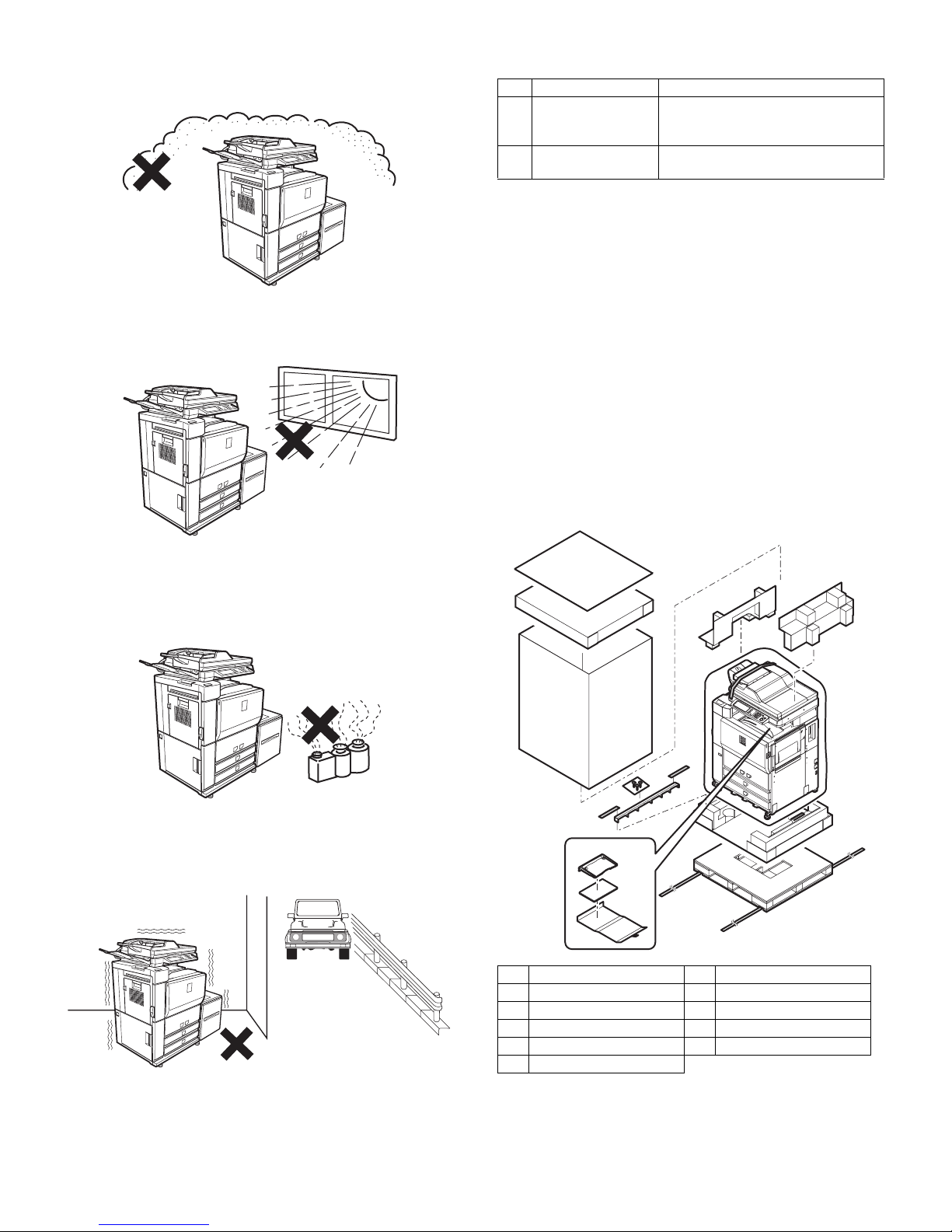
(2) Dust
If dust enters the machine, it may cause dirty copy and a paper jam,
resulting in a shortened lifetime.
(3) Direct rays of the sun
If the machine is installed under the rays of the sun, the exterior of the
machine may be discolored and abnormal copies may be produced.
(4) Gases and chemicals
Do not install the machine at a place where there are gases and chemicals. Especially be careful to avoid installation near a diazo-type
copier, which produces ammonium gas.
Copy quality may be adversely affected and a trouble may be caused.
(5) Vibration
Avoid installation near a machine which produces vibrations.
If vibrations are applied to the copier machine, copy images may be
deflected and a trouble may be caused.
2. Transit and delivery
A. Implements, facility, and manpower
It is recommendable to use a forklift for bringing in the machine for
safety.
If no forklift is available, manpower of four or more persons is required.
The machine is considerably heavy, and requires safety precautions
for delivery and installation.
Transit of the machine must be made in packed condition to the installing place.
B. Delivery
Remove the packing materials prior to installation in the ofice environment.
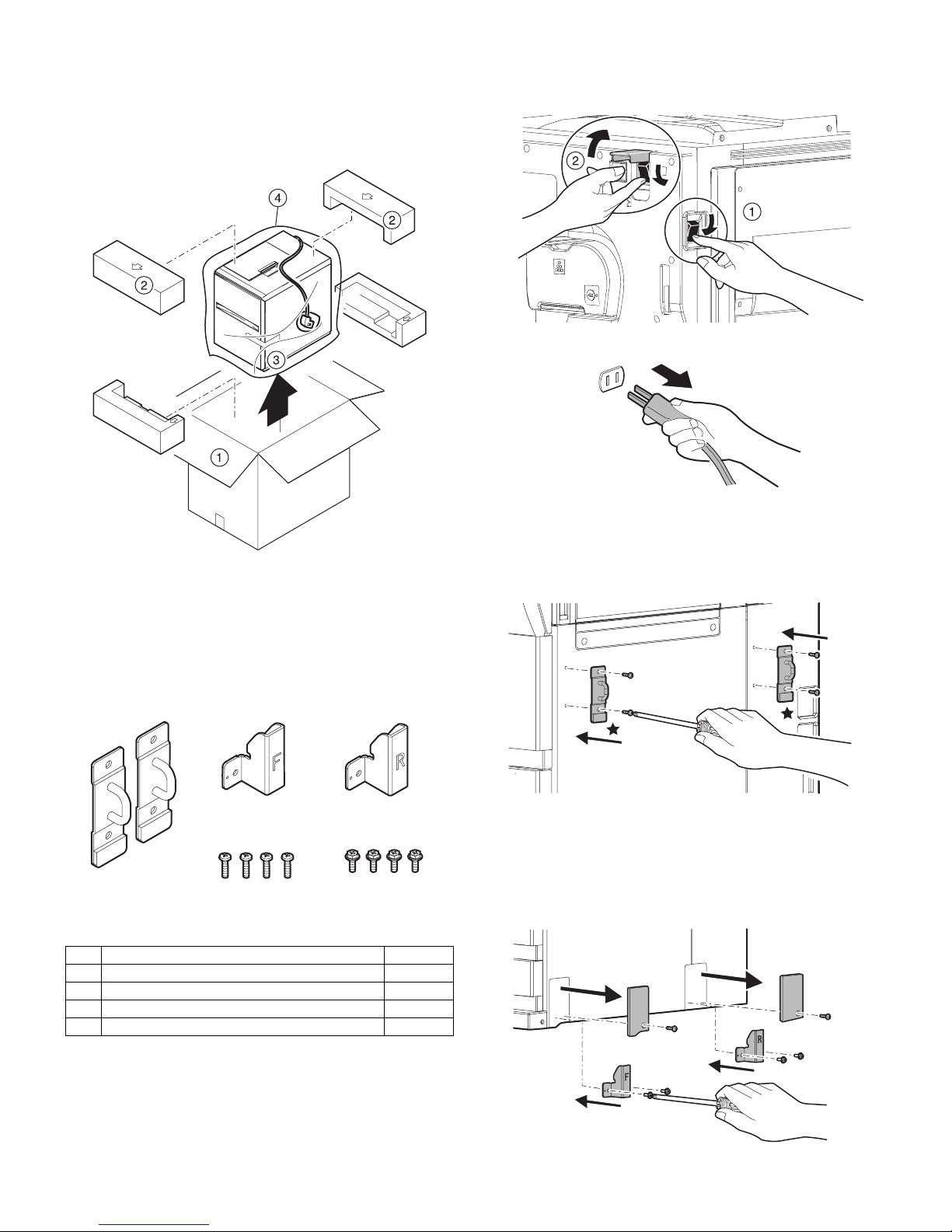
3. Unpacking
A. Unpacking procedure
1) Remove the PP band.
2) Remove the top case.
3) Remove the internal packing pads and the items packed together
with the machine.
No. Content Method
1 Implements, facility,
and manpower
Use a forklift. (If no forklift is available,
manpower of four or more persons is
required.)
2 Delivery Transit must be made in packed
condition.
1 PP band 7 Polyethylene bag
2 Top case 8 Bottom case unit
3 Pack case 9 Accessory unit
4 Skid pad 10 Paper exit tray AS
5 Top pad R 11 Operation manual
6 Top pad L
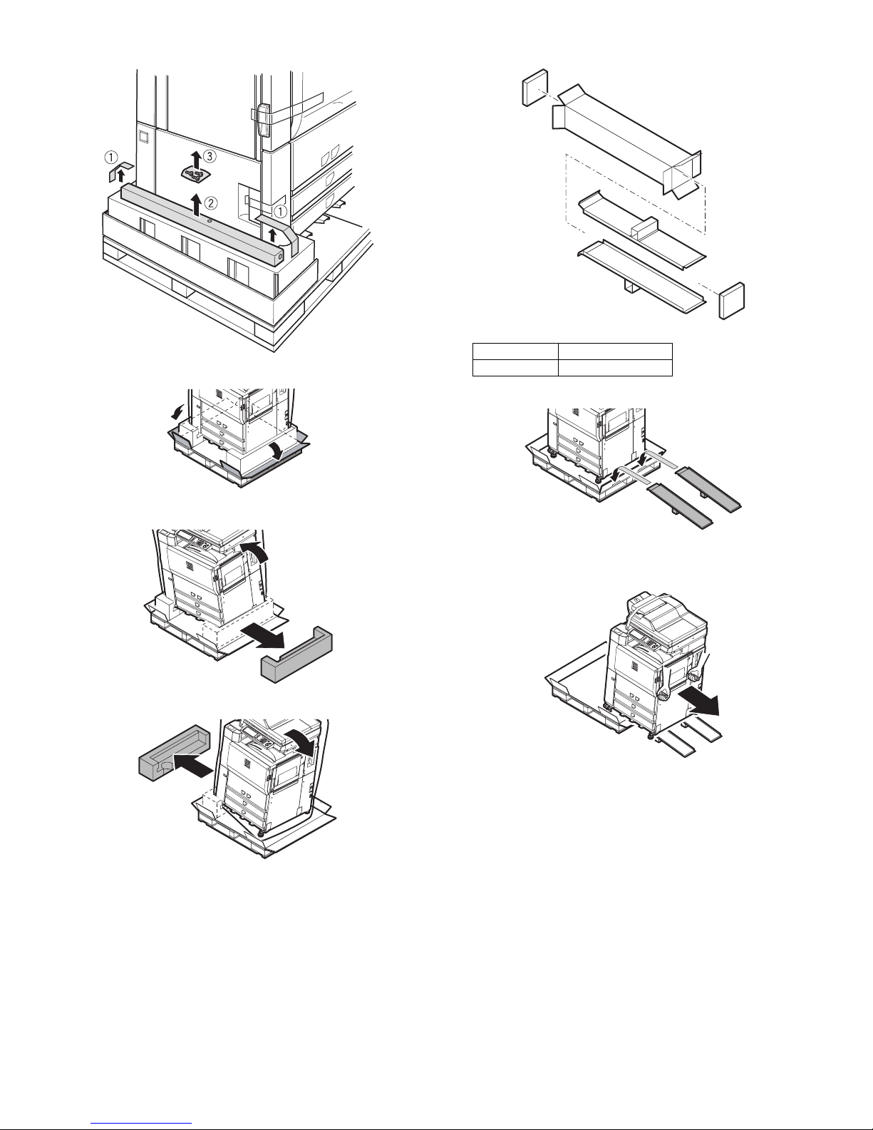
AR-M550/M620/M700 INSTALLATION MANUAL (AR-M550/M620/M700) 1 - 3
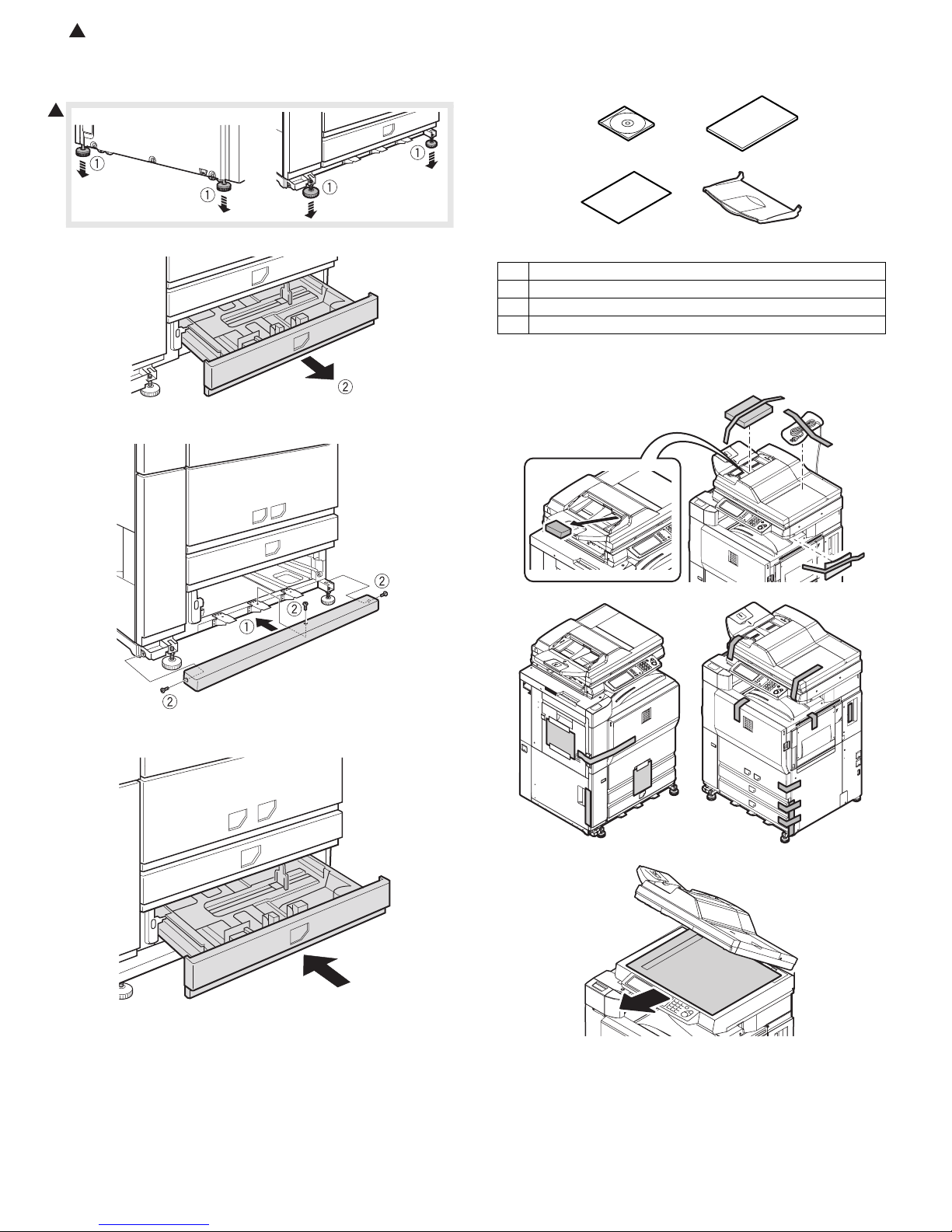
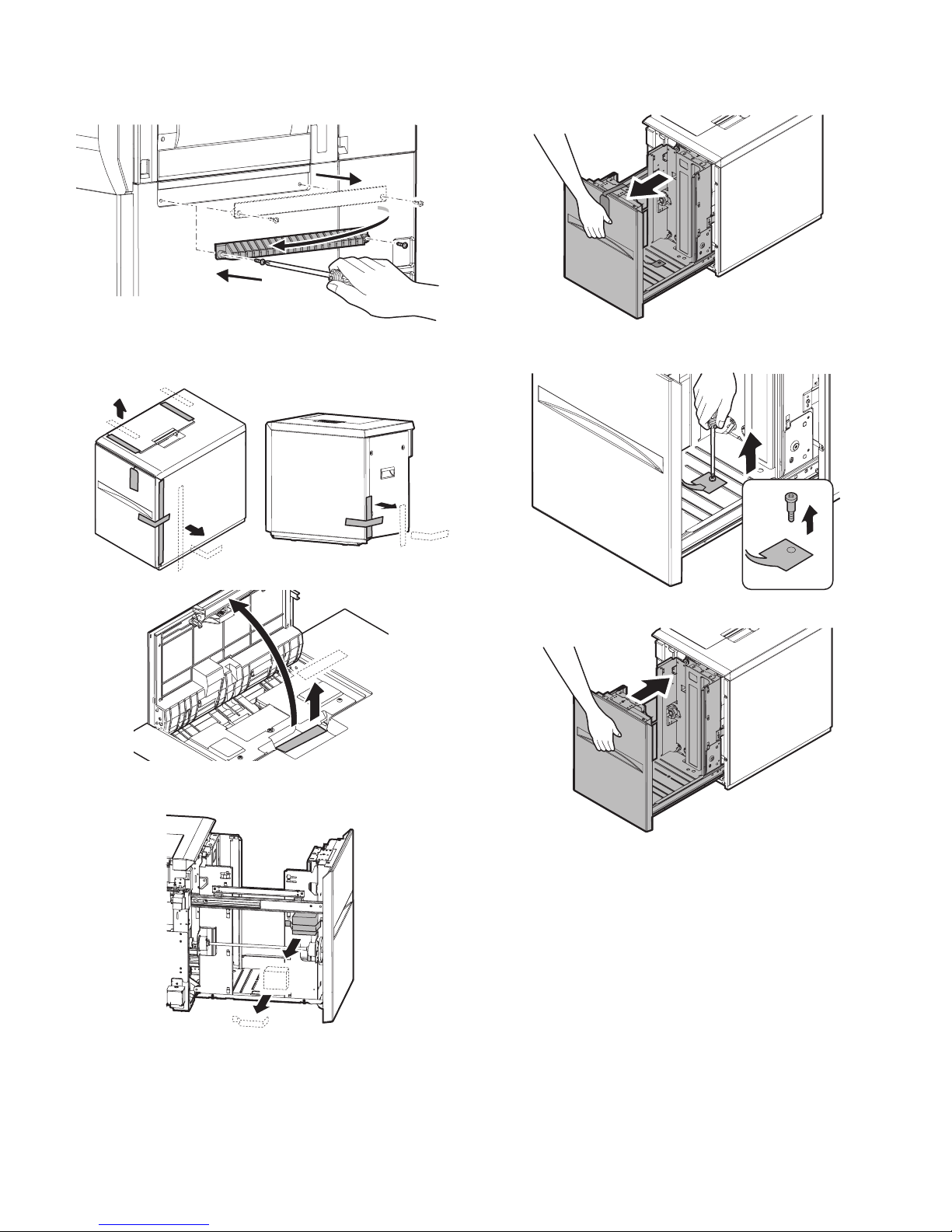
4) Remove the adjuster cover and the screw (in the bag).
5) Cut the four corners of the bottom case.
6) Lift the machine slightly, and remove the bottom pad L.
7) Lift the machine slightly, and remove the bottom pad R.
8) Remove the slope.
∗ Slope: Parts
9) Attach the slope to the concave section of the skid.
10) Hold the machine grips and push them down in the arrow direc-
tion.
Part name Part code
Skid slope DKiT-0367FCZZ
: Feb. 9 2004
2
AR-M550/M620/M700 INSTALLATION MANUAL (AR-M550/M620/M700) 1 - 4
B. Adjuster cover installation
1) Move the main unit to the installing position, and turn the adjuster to
fix the main unit.
2) Remove the bottom tray from the main unit.
3) Install the adjuster cover to the main unit.
4) Insert the bottom tray into the main unit.
Note: This machine includes a hard disk drive, which must be pro-
tected against vibrations and shocks.
Never move the machine with the power ON.
Packed items
C. Remove the fixing tape and the reinforcing
material
2
1 Driver (CD-ROM) x 1
2 Operation manual x 1
3 Delivery and installation report x 1
4 Paper exit tray x 1
12
34
AR-M550/M620/M700 INSTALLATION MANUAL (AR-M550/M620/M700) 1 - 5
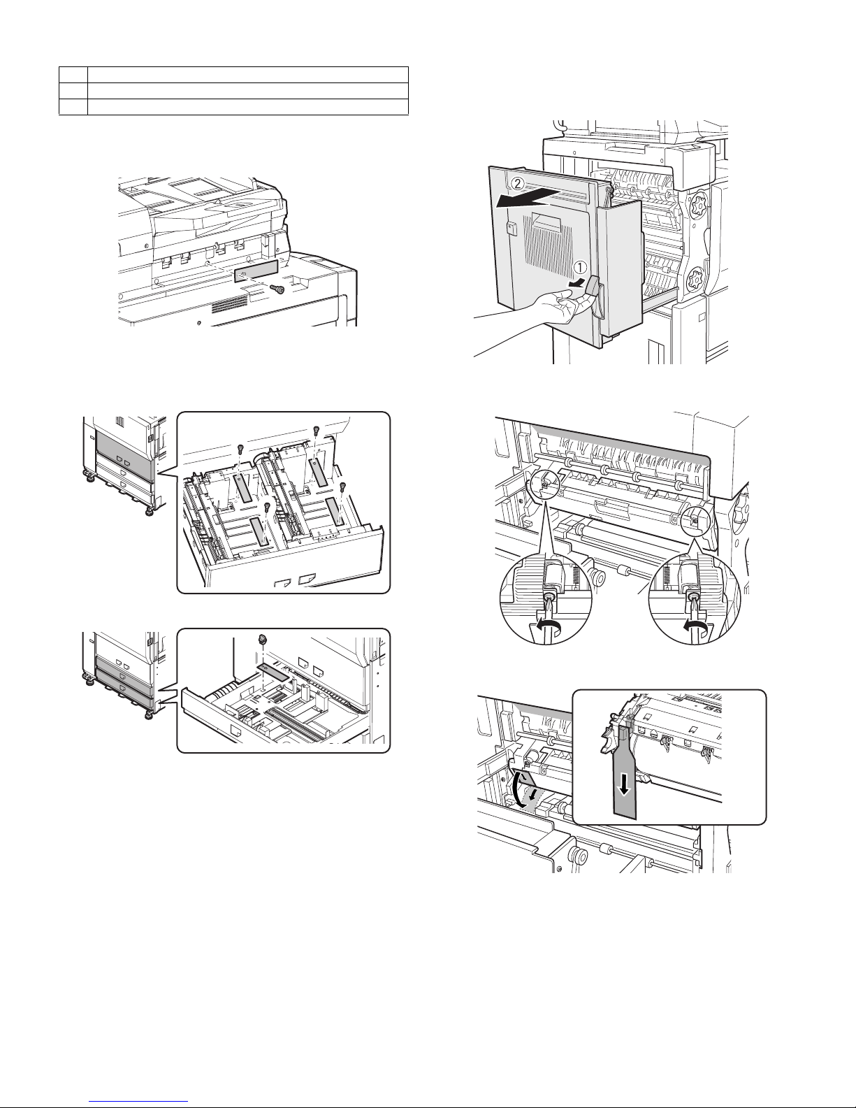
D. Lock release
(1) No. 2/3 mirror base lock release
Remove the No. 2/3 mirror base fixing screw and the label of note for
unpacking on the left side.
(2) Tray rotation release plate lock release
Remove the paper feed tray rotation plate fixing screw and the label of
note for tray.
[Tray 1, Tray 2]
[Tray 3, Tray 4]
E. Press the fusing section (upper and lower heat
rollers) and remove the process separation pawl
fixing block.
1) Pull the knob on the left door to pull out the left door.
2) Turn the pressing screw in the fusing section as shown in the figure
below (fully loosen it) to press the heat roller.
3) Remove the separation pawl fixing block from the process unit.
4) Replace the left door.
Lock position
1 No. 2/3 mirror base lock screw
2 Tray rotation plate fixing material
2
AR-M550/M620/M700 INSTALLATION MANUAL (AR-M550/M620/M700) 1 - 6
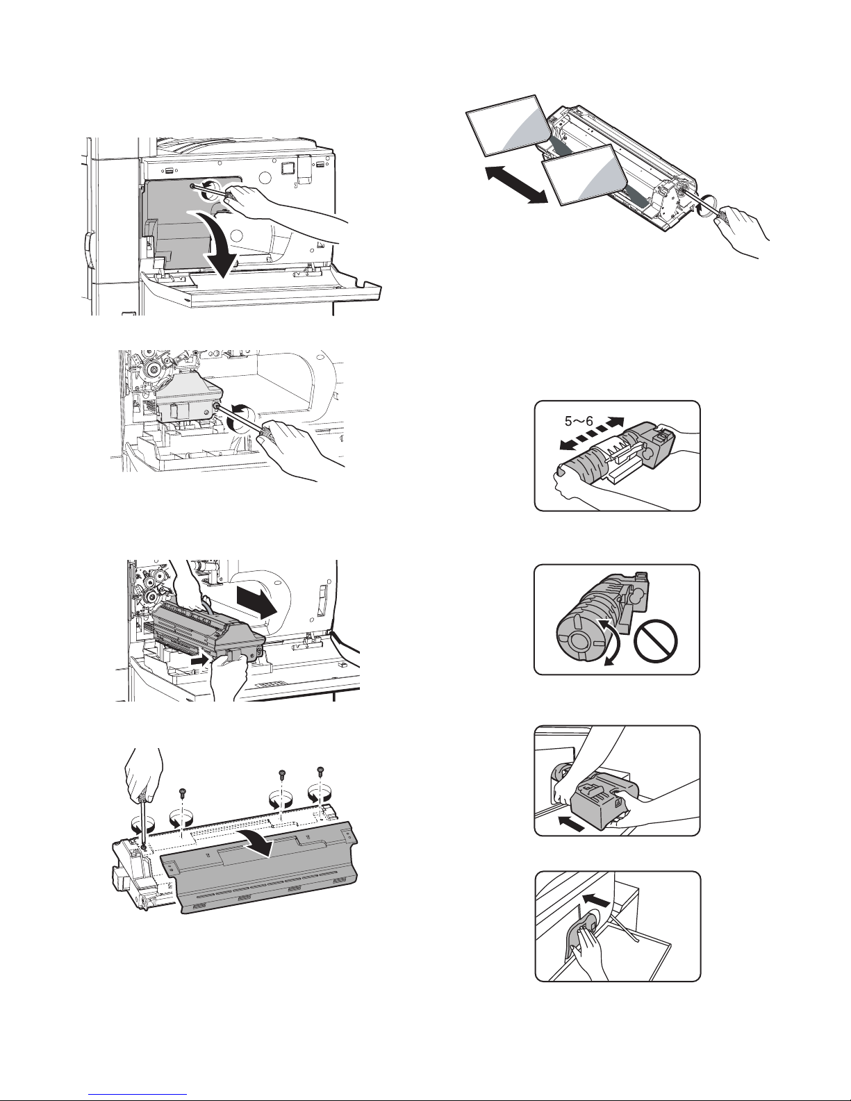
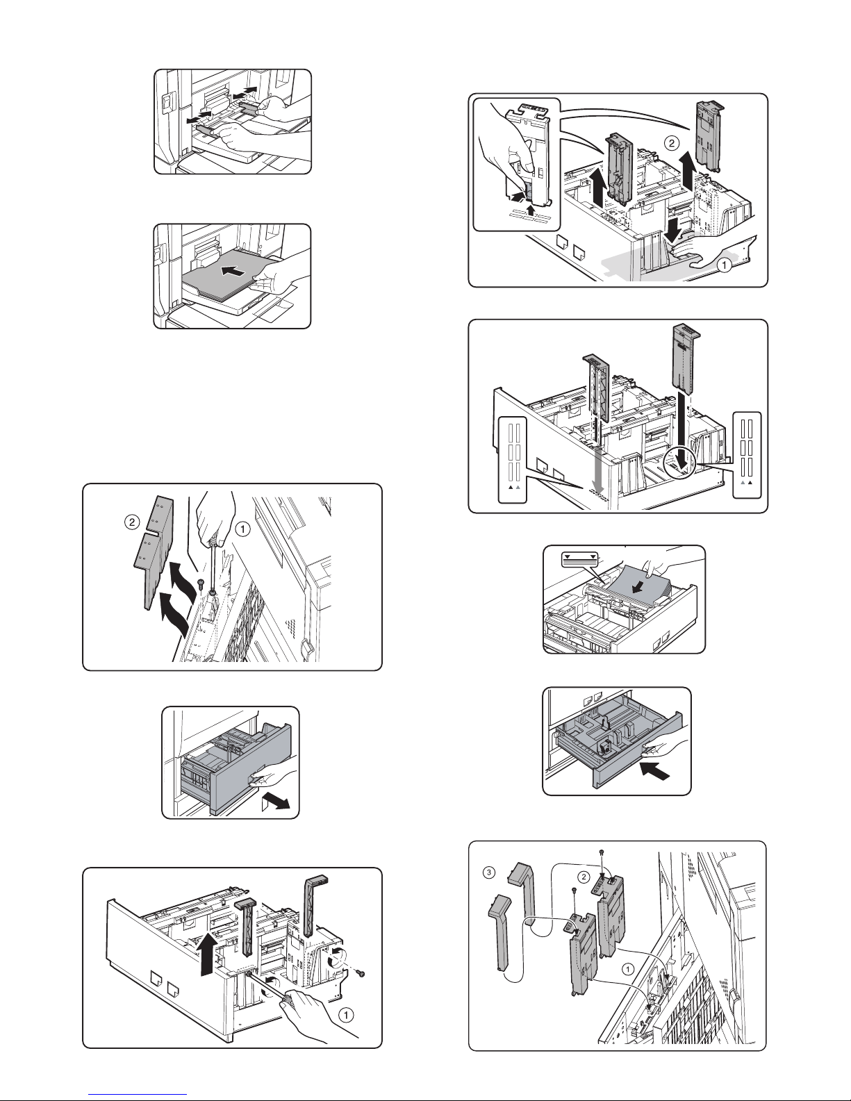
F. Set developer
(1) Supply developer
1) Open the front cabinet.
2) Loosen the blue screw of the process cover, and tilt down the process cover toward you.
3) Loosen the blue screw which is fixing the developing unit.
4) While pressing the developing unit lock lever, pull out the developing unit.
Hold the strap of the developing unit and remove the developing
unit.
5) Remove the four fixing screws of toner hopper in the developing
unit.
6) While supplying developer from the developer supply port of the
developing unit, turn the MG gear clockwise with a plus screwdriver
to supply all developer to the developing unit.
7) Install the toner hopper to the developing unit.
8) Insert the developing unit to the main unit and fix it with the blue
screw.
9) Close the process cover and fix it with the blue screw.
(2) Toner set
1) Remove the toner cartridge from the box, and shake it several
times horizontally.
Note: Be sure to shake the toner cartridge horizontally.
Be careful not rotate as shown in the figure below.
2) Insert the toner cartridge into the main unit insertion port as shown
below. In this case, do not turn the cartridge.
3) Insert the toner cartridge until it is locked.
2
1
: Feb. 9 2004
2
(3) Set the toner density reference control level
Insert the power plug into the power outlet, and turn on the power
switch of the main unit.
1) With the front cabinet open, enter the SIM 25-2 mode.
2) Close the front cabinet.
3) Press START key to execute the simulation. Toner is stirred for 3
minutes, and sampling of the toner density control sensor value is
repeated 16 times. The average level of the sensor detection level
is set (stored) as the reference toner density control value.
Note: The 70-sheet machine (AR-M700N/U) performs resetting after
2
normal completion of toner concentration control level setting
operation (3 min) by SIM25-2, and supplies toner during warming up when the fuser heater lamp is turned ON in order to
increase the toner concentration level by 0.5%.
When there is some toner in the intermediate hopper, the above
toner supply operation is completed in about 90 sec.
Since the warming-up time of fusing is within 2 min, the machine
goes to the print ready state in 1 min 30 sec or 2 min.
When, however, there is no toner in the intermediate hopper (on
installation, etc.), toner is supplied from the toner bottle to the
developing unit and it takes more time than the above to reach
the specified toner concentration level, that is, it takes about 200
sec for the machine to go to the print ready state.
Toner supply operation to increase the toner concentration level
by 0.5% after completion of SIM25-2 is performed only in the 70sheet machine, and not performed in the 55/62-sheet machines.
4) Slowly insert the tray 1 and the tray 2.
(2) Supply paper to the tray 3 and the tray 4
The tray 3 is for 11" x 17" to 5-1/2" x 8-1/2"R size (A3 size to A5R) and
special paper, and the tray 4 is for 11" x 17" to 5-1/2" x 8-1/2"R size
(A3 size to A5R) paper.
(For the kinds of paper and special paper, refer to the specifications of
this manual.)
1) Pull out the tray 3 and the tray 4 until they stop.
2) Supply paper so that the specified line is not exceeded.
3) Slowly insert the tray 3 or the tray 4.
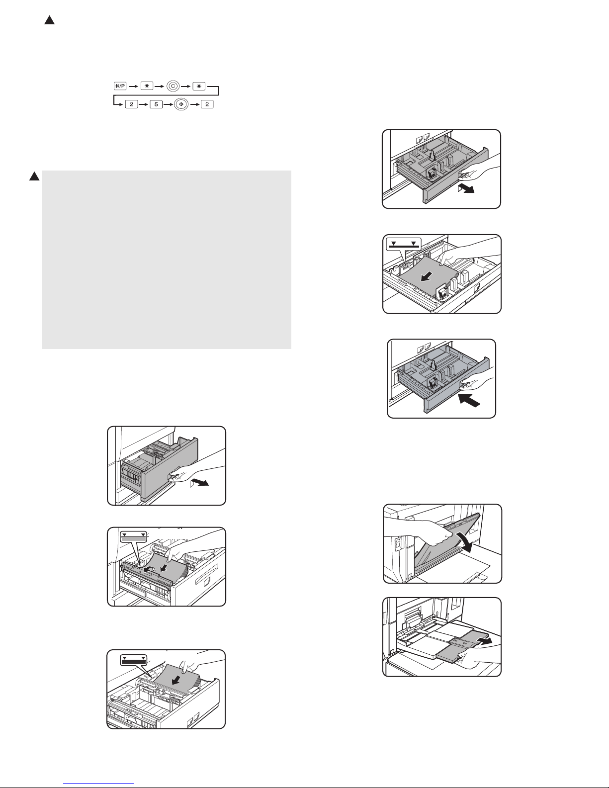
G. Paper supply
(1) Supply to tray 1 and tray 2
The tray 1 is for A4 or 8-1/2" x 11" paper, and the tray 2 is for A4 or B5
or 8-1/2" x 11" paper. (The factory setting of the tray 2 is B5.)
1) Pull out the tray 1 and the tray 2 until they stop.
2) Lift the paper guide, and supply paper to the tray 1.
Specified line
After supplying paper, be sure to return the paper guide to the original position.
3) Supply paper to the tray 2 similarly.
(3) Supply paper to the manual paper feed tray.
The manual paper feed tray is for 11" x 17" to 8-1/2" x 11"R size (A3
size to A5R) and special paper.
(For the kinds of paper and special paper, refer to the specifications of
this manual.)
1) Open the manual paper feed tray.
Specified line
Note: Supply paper so that the paper quantity level does not exceed
the specified line.
AR-M550/M620/M700 INSTALLATION MANUAL (AR-M550/M620/M700) 1 - 7
Note: When setting 11" x 17", 8-1/2" x 14", 8-1/2" x 13", or 8-1/2" x
11"R (A3, B4, or A4R) paper, be sure to pull out the auxiliary
tray.
If it is not pulled out completely, the size of paper set on the
manual paper feed tray is not displayed properly.
AR-M550/M620/M700 INSTALLATION MANUAL (AR-M550/M620/M700) 1 - 8
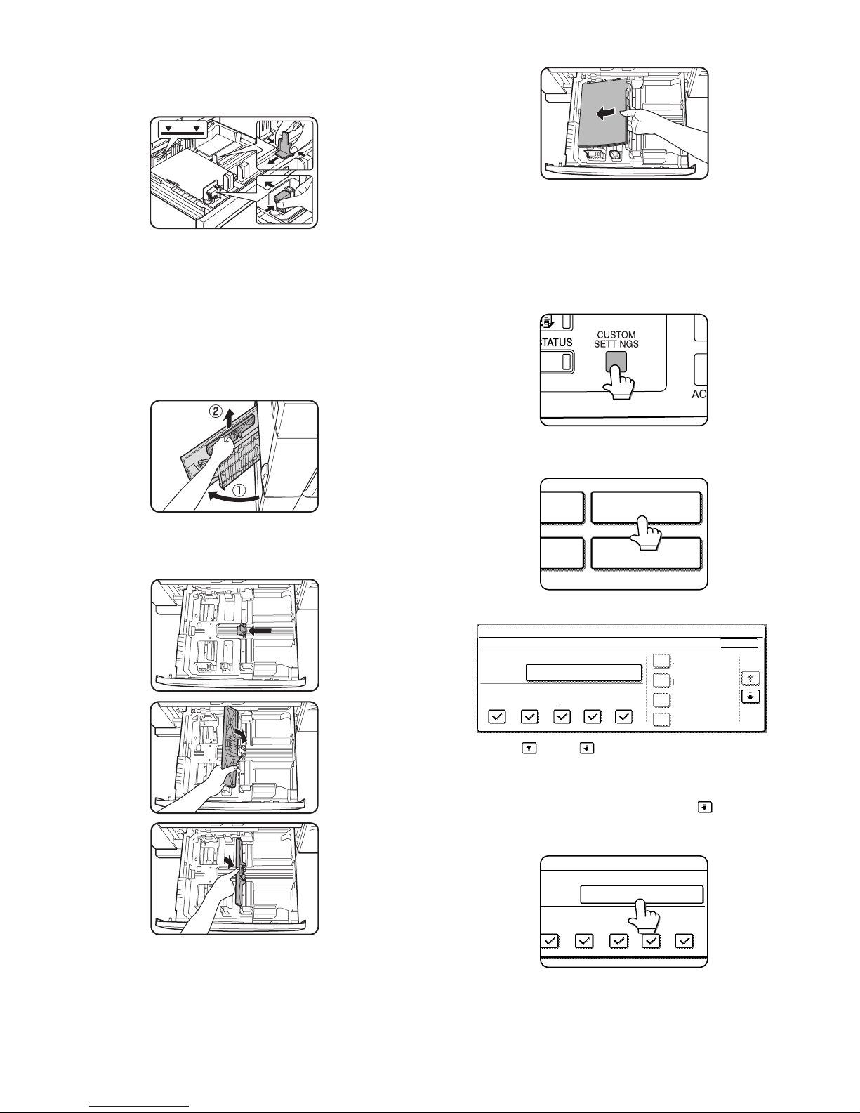
2) Set the manual paper feed guide to the set paper size.
3) Set the paper with print face up and insert until it makes contact
with the manual paper feed guide.
Note: If there is any gap between paper and the manual paper feed
guide, skew feed or wrinkles may be caused. Be sure to set
paper so that there is no gap between paper and the guide.
(4) Tray 2 paper size change
When changing the paper size of the tray 2 from B5 to A4, replace the
guide plate with the A4-exclusive regulation plate.
1) Remove the A4-exclusive regulation plate from the storage position
left inside of the machine. (It is fixed with a fixing screw under the
tab paper guide.)
2) Pull out the tray 1 and the tray 2.
3) Remove the B5 size regulation plate and the rear edge regulation
plates F and R from the tray 2.
When removing the B5 size regulation plate, slightly press the
paper feed base plate downward and press the hook under the regulation plate to remove.
4) Install the A4 size regulation plate.
5) Supply paper to the tray 2.
6) Push the tray 1 and the tray 2.
Note: Store the B5 size regulation plate and the rear edge regulation
plates F and R for future use.
A4
LT
A4
LT
Specified line
AR-M550/M620/M700 INSTALLATION MANUAL (AR-M550/M620/M700) 1 - 9
(5) Tray 3 or tray 4 paper size change
1) Pull out the tray 3 or the tray 4.
2) Hold and slide the fixing knob (slide system) of the partition plates A
and B to fit with the size of paper to be supplied.
3) Supply paper into the tray.
4) Push the tray.
Note: Note that a certain special paper cannot be used for the tray 4.
To use the special paper, use the tray 3.
(6) Tab paper setting
To use tab paper, install the exclusive-use guide to the tray 3.
Note that the tray 4 cannot be used.
1) Remove the exclusive-use guide from the storage position left
inside of the machine.
2) Pull out the tray 3.
3) Slide the partition plate to tab paper as shown in the figure below
and install it so that it covers the partition plate.
4) Supply tab paper with the print face up into the tray 3.
5) Push the tray 3.
(7) Setting the paper type and paper size
Follow these steps to change the paper type setting when the paper
type has been changed in a paper tray. For the paper types that can be
used in each tray.
1) Press the [CUSTOM SETTINGS] key.
The custom setting menu screen will appear.
2) Touch the [TRAY SETTINGS] key.
The paper tray selection screen will appear.
3) Display the setting screen of the desired paper tray.
Touch the key or key to display the setting screen of the
desired paper tray.
Note: To automatically switch to a tray with the same size and type of
paper (if there is one) in the event that the paper tray runs out of
paper, display the last screen with the key and select
[AUTO TRAY SWITCHING].
4) Touch the [TYPE / SIZE] key.
TRAY SETTINGS
TA
PRINTER
CONDITION
1/8
PLAIN / 8 x11
OK
PRINT
TRAY SETTINGS
TYPE / SIZE
CUSTOM SETTINGS
TRAY1
FAX
I-FAX
COPY
DOC.
FILING
FIXED PAPER
DISABLE DUPLEX
DISABLE STAPLE
DISABLE PUNCH
1
/
2
TYPE / SIZE
TRAY3
PRINT
COPY
I-FAX
DOC.
FILING
FAX
PLAIN / 8 x11
1
/
2

AR-M550/M620/M700 INSTALLATION MANUAL (AR-M550/M620/M700) 1 - 10
5) Select the type of paper that was loaded in the tray.
Example: The paper type of tray 3 is selected.
Touch the desired paper type to select it. The paper size setting
screen will appear.
Notes:
• Tabbed paper can only be used in tray 3 and the bypass tray.
• Label sheet, OHP: Tray 1, 2, 4, and 5 cannot be used.
• Heavy paper: Tray 1, 2, and 5 cannot be used.
6) Select the size of paper that was loaded in the tray.
Touch the appropriate keys (checkboxes).
Note: Sizes that can be selected vary depending on the selected
paper type.
7) Touch the [OK] key in the size setting screen.
You will return to the tray setting screen of step 3.
8) Select output functions that can be used with the selected tray.
Touch the checkboxes under the desired items to select them.
Note: When the inserter (option) is selected, printing of faxes and
Internet faxes is not possible.
User type
Select a "User type" when the name of the paper type does not appear
in the selections or when you wish to select the tray attributes yourself.
Touch the key in step 5 on the previous page to display the user
type selection screen and then select a user type.
9) Set the attributes of the paper tray only if you have selected a user
type. (Touch the checkboxes to the left of the items to select them.)
Notes:
• Paper tray attributes cannot be set when a user type is not selected.
• Tray attributes depend on the selected paper.
• "FIXED PAPER SIDE" and "DISABLE DUPLEX" cannot be simulta-
neously enabled.
10) Configure paper settings for each tray and then touch the [OK] key
to exit.
Note: The size and type of paper loaded in the bypass tray can also
be set from the paper setting screen. Touch the [PAPER
SELECT] key in the main screen to display the paper selection
screen, and then touch the [PAPER SELECT] key of the bypass
tray and go to step 5.
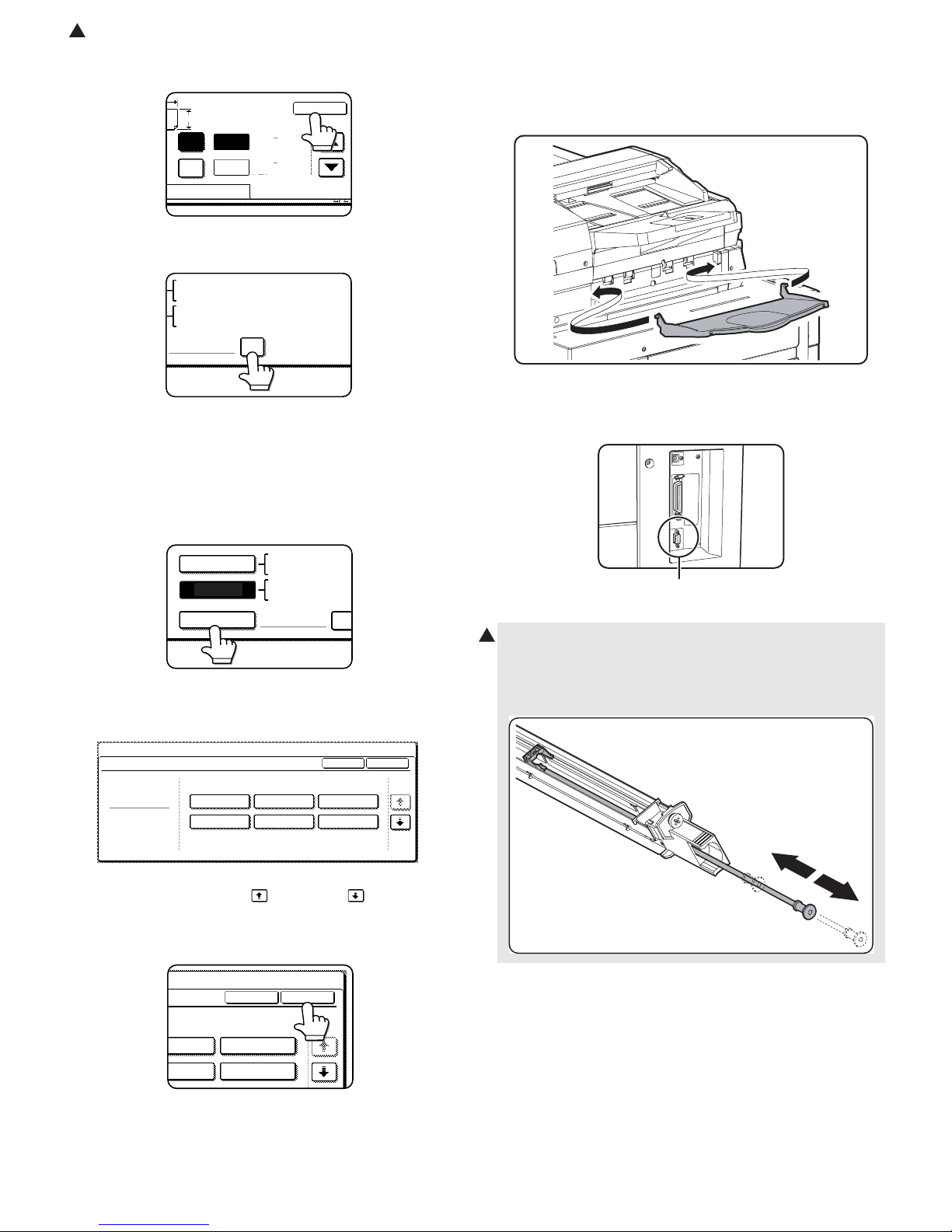
(8) Setting the paper size when a special size is loaded
Note: Special sizes of paper cannot be loaded in trays 1, 2, 4 and 5.
[Trays 3 and the bypass tray]
1) Perform steps 1 through 5 of "Setting the paper type and paper
size".
2) Touch the [SIZE INPUT] key and then touch the [INCH] tab.
(The size entry palette appears.)
3) Touch the key or the key to enter the X (width) and Y
(length) dimensions of the paper.
X (width) is initially selected. To enter Y (length), touch the [Y] key
and then enter the length.
[AUTO-INCH] key: Select when you have loaded an inch-based
size of paper.
[AUTO-AB] key: Select when you have loaded an AB size of
paper.
[SIZE INPUT] key: Select to directly enter a paper size.
[NON STANDARD
SIZE] checkbox:
Select when you have loaded a non-standard
size of paper.
CANCEL
1/2
PLAIN
RECYCLED
PRE-PRINTED PRE-PUNCHED
LETTER HEAD
COLOR
HEAVY PAPER
TAB PAPER
LABELS
TRANSPARENCY
TRAY 3 TYPE/SIZE SETTING
SELECT THE PAPER TYPE.
CUSTOM SETTINGS
1/2
11X17,8 X14,8 X11
8 X11R,7 X10 ,5 X8 R
1
/
2
1
/
2
1
/
2
1
/
2
1
/
4
1
/
2
1
/
2
A3,A4,A4R,A5R,B4,B5
B5R,216X330(8 X13)
1
/
2
TYPE
OK
PLAIN
TRAY3 TYPE/SIZE SETTING
CUSTOM SETTINGS
TYPE
AUTO-INCH
SIZE INPUT
AUTO-AB
SIZE
X Y
NON STANDARD
SIZE
2/2
PRINT
COPY
FAX
I-FAX
DOC.
FILING
CUSTOM SETTINGS
TRAY 3 TYPE/SIZE SETTING
2/2
USER TYPE 1
CANCEL
SELECT THE PAPER TYPE
USER TYPE 5
USER TYPE 2
USER TYPE 6
USER TYPE 3
USER TYPE 7
USER TYPE 4
1/2
"FIXED
PAPER SIDE":
Select when paper is to be loaded print side down
in the tray.
Make sure a checkmark does not appear when
paper is to be loaded print side up.
• If the two-sided function is prohibited in
"DISABLING OF DUPLEX" in the key operator
programs, do not use this setting.
"DISABLE
DUPLEX":
Prohibits two-sided printing.
Enable when the back side of the paper cannot be
printed on.
"DISABLE
STAPLE":
Prohibits stapling. Enable when using special
papers such as transparency film and label sheets.
"DISABLE
PUNCH":
Prohibits punching. Enable when using special
papers such as transparency film and label sheets.
FIXED PAPER SIDE
DOC.
FILING
DISABLE DUPLEX
DISABLE STAPLE
DISABLE PUNCH
AB
Y
11
17
X
(5 1/2 17)
inch
INCH
OK
(5 1/2 11 5/8)
inch
Y
X
AB
Y
11
17
Y
X
INCH
OK
(5 1/2 17)
inch
(5 1/2 11 5/8)
inch
: Feb. 9 2004
2
AR-M550/M620/M700 INSTALLATION MANUAL (AR-M550/M620/M700) 1 - 11
4) Touch the [OK] key. (You will return to the size setting screen of
step 2.)
5) If the paper is a non-standard size, select the [NON STANDARD
SIZE] checkbox.
6) Perform steps 7 through 10 of "Setting the paper type and paper
size".
[Inserter (option)]
1) Perform steps 1 through 5 of "Setting the paper type and paper
size".
2) Touch the [SIZE SELECT] key. (The size selection screen
appears.)
Note: When tabbed paper is selected, the [NON STANDARD SIZE]
checkbox of the [SIZE SELECT] key cannot be selected.
3) Select the desired paper size.
There are separate screens for inch-based paper selection and AB
paper selection. Touch the key or the key to switch
between the screens.
4) Touch the [OK] key. (You will return to the size setting screen of
step 2.)
5) Perform steps 7 through 10 of "Setting the paper type and paper
size".
H. The other parts setting
(1) Document exit tray installation
Install the document exit tray to the scanner unit as shown in the figure
below.
(2) Other notes
Check to insure that the cable connected to the service terminal (A in
the figure below) is 3m or less.
X
AB
Y
11
17
Y
X
INCH
OK
(5 1/2 17)
inch
(5 1/2 11 5/8)
inch
NON STANDARD
SIZE
11X17,8 X14,8 X11
1
/
2
1
/
2
8 X11R,7 X10 ,5 X8 R
1
/
2
1
/
4
1
/
2
1
/
2
1
/
2
A3,A4,A4R,A5R,B4,B5
B5R,216x330(8 x13)
X17 Y11
5
/
8
1
/
2
SIZE SELECT
11X17,8 X14,8
X
1
/
2
1
/
2
8 X11R,7 X10 ,5
1
/
2
1
/
4
1
/
2
A3,A4,A4R,A5R,B
AUTO-INCH
AUTO-AB
B5R
1/2
PLAIN
11X17
OK
TYPE
INSERTER TYPE/SIZE SETTING
TYPE
CUSTOM SETTINGS
8 X14
1
/
2
8 X11
1
/
2
8 X11R
1
/
2
7 X10
1
/
4
1
/
2
5 X8 R
1
/
2
1
/
2
SIZE
1
/
2
X10
/
4
1
/
2
1/2
TYPE
8 X11
1
/
2
5 X8 R
1
/
2
1
/
2
SIZE
OK
4. Cleaning
A. Main charger
1) Reciprocate the MC cleaner shaft back and forth to clean the electrode tip.
(A)
2
AR-M550/M620/M700 INSTALLATION MANUAL (AR-M550/M620/M700) 1 - 12
5. Image quality check
Check the following contents. For adjustment and check procedures,
refer to the chapter of adjustments.
A. Focus (Resolution)
B. Copy image off-center
C. Image loss, void area
6. Specifications setting
Use SIM 26 to set the customer's desired specifications.
7. Recording of setting and adjustment
data
Use SIM 22-6 to print and keep the various setting and adjustment
data (list).
When a memory trouble occurs, or when the PCU PWB or the ICU
PWB is replaced, if the above information is not available, all the
adjustment must be performed from the beginning again.
If the above information is available, however, directly enter the setting
and adjustment values for efficient servicing.
8. Preparation for transit
When moving the copier, turn off the power and perform the following
works.
1) Remove the paper from the paper tray.
2) Remove the developing unit from the main unit.
3) Lock the position which was released at installation (see the page
1-5).
4) Remove the adjuster cover, and raise the adjuster (see the page 1-
5).
Note: Since the main unit includes the hard disk drive, be careful not
to apply vibrations and shocks during transit.
Sim No. Content
26 2 Used to set the paper size of the tray 2 and the large
capacity tray. (When the paper size is changed, this
simulation must be used to change the paper size by
software.)
5 A3 paper 1 count/2 count setting
Used to set the count mode of the total counter, the
developer counter, and the maintenance counter.
6 Specifications depending on the destination
18 Used to set YES/NO of toner save operation. (This
function is valid only in Japan and UK versions.)
35 Used to set whether the trouble history is displayed as
one time trouble or the number of times of trouble.
AR-M550/M620/M700 INSTALLATION MANUAL (AR-LC6) 2 - 1
[2] AR-LC6 UNPACKING AND
INSTALLATION
1. Unpacking
(Removal of the main unit)
2. Installation
<Before installation>
• Packaged parts check
Check to insure that all the following parts are packaged.
• Check that the printer is in stand-by state.
Check that the DATA indicator on the operation panel is neither lit
nor blinking.
Parts included
A. Turn off the power of the main unit.
1) Turn OFF the power switch on the right side of the main unit.
2) Open the front cabinet, and turn OFF the main power switch.
3) Disconnect the power plug from the power outlet.
B. Attach the upper mounting plates and the lower
front/rear connecting plates.
1) Attach the two upper mounting plates with the rubber portion (★)
down to the right side of the main unit using screws A (two for
each).
2) Remove the fixing screw of the front/rear cover on the lower right
side of the main unit. Attach the lower front side (engraved mark F)
of the connecting plate to the lower front side of the main unit with
two fixing screws B.
Attach the lower rear side (engraved mark R) of the connecting
plate to the lower rear side of the main unit with two fixing screws
B.
1 Upper mounting plate 2pcs.
2 Lower front connecting plate 1pc.
3 Lower rear connecting plate 1pc.
4 Fixing screw A (M4 x 16 small screw bind uniqlo) 4pcs.
5 Fixing screw B (Hex washer S tight M4 x 12) 4pcs.
1
23
45
AR-M550/M620/M700 INSTALLATION MANUAL (AR-LC6) 2 - 2
3) Remove the fixing screws (2 pcs.) of the machine entry port, and
remove the entry port cover.
4) Attach the entry port cover reversely to the machine and fix it with
the two fixing screws which was removed in procedure 3).
C. Fixing material and packaged part removal
1) Remove the fixing material from the large capacity paper feed tray.
2) Remove the fixing material from the packaged part, and remove
the packaged part.
D. Remove the paper feed base screw of the large
capacity tray.
1) Slowly pull out the paper feed base tray until it stops.
2) Remove the paper feed base fixing screw (1 pc.) of the large
capacity tray.
3) Push the large capacity tray slowly into the original position.
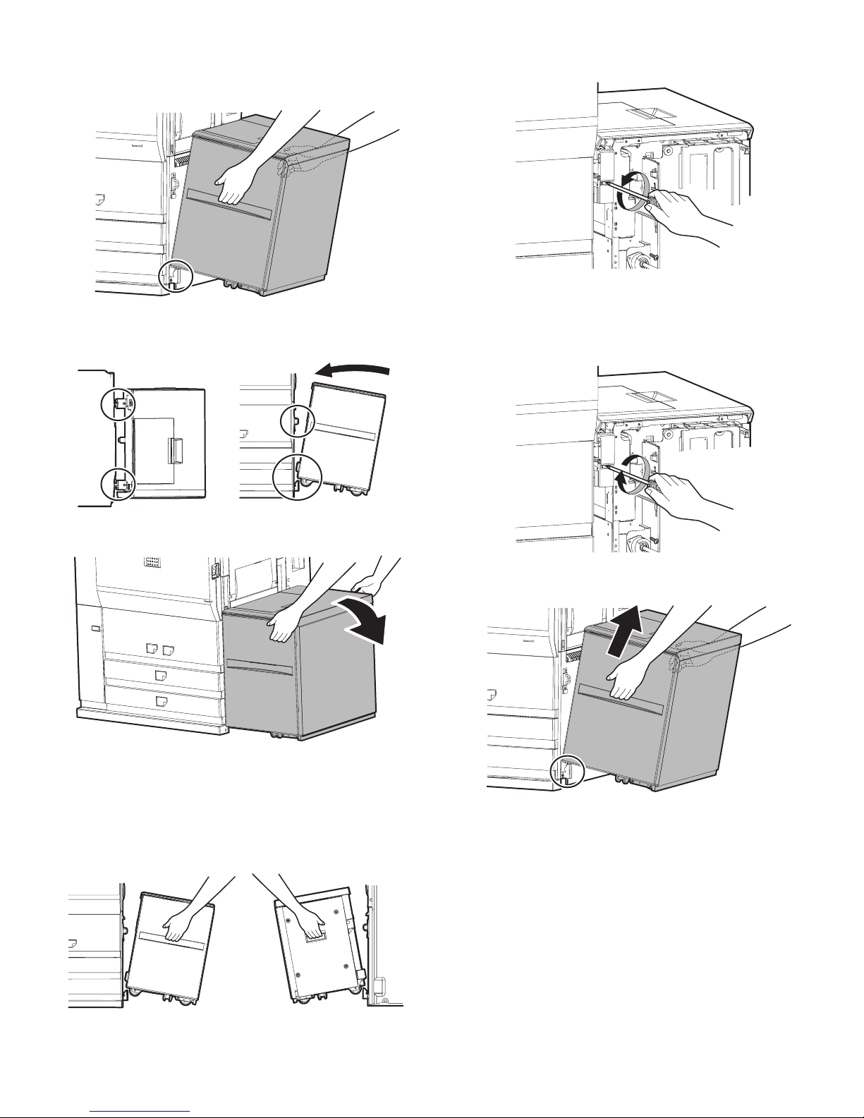
AR-M550/M620/M700 INSTALLATION MANUAL (AR-LC6) 2 - 3
E. Attach the large capacity tray to the main unit.
1) Hold the grips of the front and the rear cabinets with both hands,
and lift the left side.
2) Hang the metal fixture of the large capacity tray on the lower front/
rear side of the connecting plate on the main unit side.
Push the large capacity tray onto the main unit and attach it.
At that time, check that the large capacity tray is locked to the main
unit.
∗ If lock is incomplete, when the power switch is turned on, the mes-
sage, “Check installation of tray 5” is displayed on the operation
panel.
∗ Push the large capacity tray onto the machine, and lock it securely.
[Note]
Note 1): When lifting the LCC, insert fingers into the grip sections of
the front and rear cabinets and install slowly.
Note 2): Turn the lock release screw of the front cover counterclock-
wise to loosen and check that the screw is free.
∗ If the screw is tight at that time, installation will be incom-
plete.
<<How to separate the large capacity tray from the main unit>>
1) Turn the lock release screw of the front cover clockwise and
tighten the screw securely to release lock.
2) Then hold the grips of the front and the rear cabinets with both
hands, and lift the left side. The large capacity tray will come off.
F side R side
AR-M550/M620/M700 INSTALLATION MANUAL (AR-LC6) 2 - 4
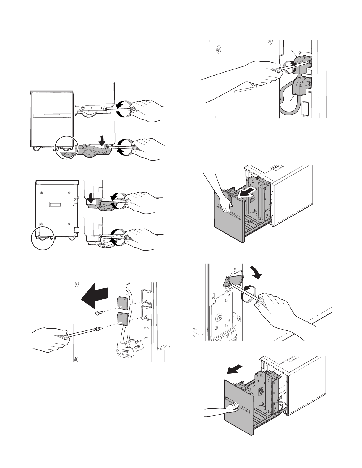
F. Adjust the caster
1) After installing the large capacity tray to the main unit, loosen the
screws (one in the front and one in the rear) of the adjustment
caster mounting plate attached to the lower side of the large
capacity tray.
At that time, the casters of the adjustment caster mounting plate
are brought into contact with the floor by the spring force.
2) Tighten the screws of the caster mounting plate which were loosened in procedure 1).
G. Connect the connector of the large capacity tray.
1) Remove the screw (one for each) from the connector cover on the
main unit and then remove the two connector covers.
2)
Connect the large capacity tray interface harness connector and
the heating heater interface harness connector to the main unit
connector, and tighten the connector screw to fix the connector.
H. Select the paper size.
(1) Change A4 size to LT size
The factory setting of the paper size is A4. To select another size, perform the following procedures.
1) Pull out the large capacity tray until it stops.
2) Loosen the stopper fixing screw (1 pc.) on the lower right side of
the paper feed tray to disable the stopper function.
3) Then pull out the paper feed tray again until it stops.
F side
R side
a
b
AR-M550/M620/M700 INSTALLATION MANUAL (AR-LC6) 2 - 5
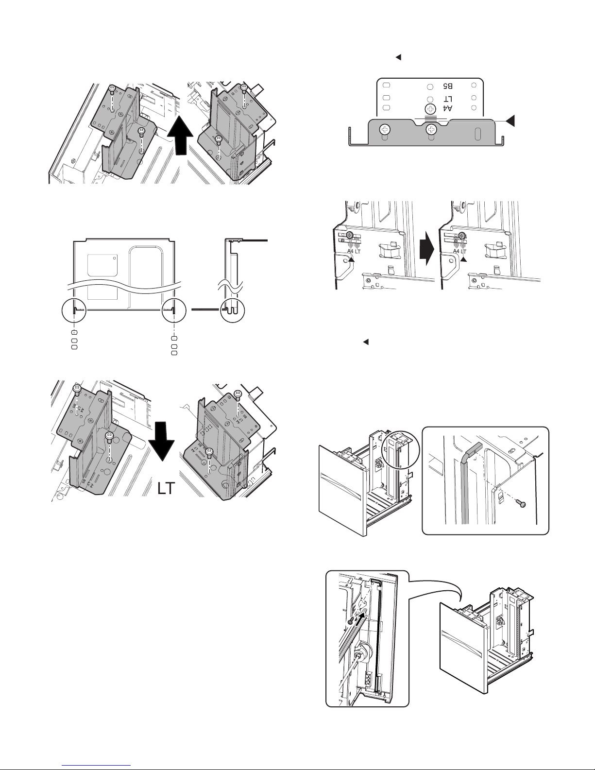
a. Side plate size change-over
1) Remove the four fixing screws (blue) which are fixing the upper
and the lower sections of the side plate F and the side plate R.
2) Then fit the paper feed tray on the lower side of the side plate F
and the side plate R with the engraved marks of the side plates
according to the size, and insert it. Also fit the upper side to the
size and fix it with the four fixing screws (blue).
b. Auxiliary guide size change-over
1) When changing the size of the side plate R, check to confirm the
mark positions of " " on the side plate R and the size guide
adjustment plate.
2) Loosen the auxiliary guide fixing screw (Flat screw 1pc).
3) Change the mark position (▲) of the auxiliary guide and the cassette R from A4 to LT, and fix them with the fixing screw (flat
screw, 1pc).
At that time, adjust so that the mark positions (▲) on the auxiliary
guide and the cassette R are at the same positions of the mark
positions ( ) of the side plate R and the size guide adjustment
plate checked in the procedure 1). (If the scale of the size guide
adjustment plate is at the center, set the position at the center. If is
it at 1mm toward the front side, set the position at 1mm toward the
front side.)
c. Rear edge shaft change-over
1) Remove the rear edge shaft fixing screw (blue) on the right side of
the paper feed tray, and remove the rear edge shaft.
2) Tighten the removed rear edge shaft with the fixing screw (blue
screw) and store it in the storage space inside the front cabinet.
F side R side
F side R side
A4 LT
[When LT size]
 Loading...