

Page 1
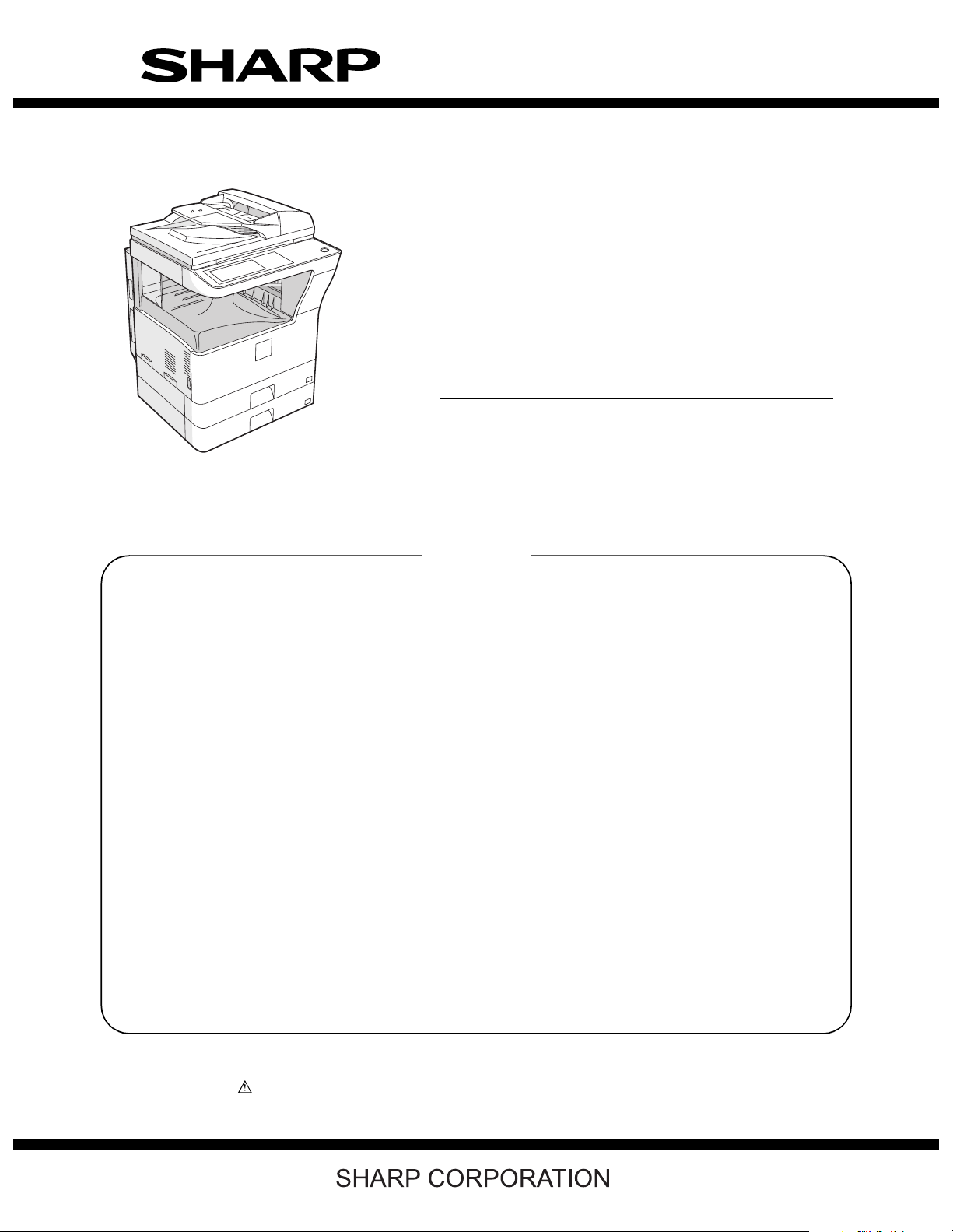
SERVICE MANUAL
CODE: 00ZAR5731/S1E
DIGITAL
MULTIFUNCTIONAL
SYSTEM
MODEL
CONTENTS
NOTE FOR SERVICING
[1] PRODUCT OUTLINE . . . . . . . . . . . . . . . . . . . . . . . . . . . . . . . . . . . 1-1
[2] SPECIFICATIONS . . . . . . . . . . . . . . . . . . . . . . . . . . . . . . . . . . . . . . 2-1
[3] CONSUMABLE PARTS. . . . . . . . . . . . . . . . . . . . . . . . . . . . . . . . . . 3-1
[4] EXTERNAL VIEW AND INTERNAL STRUCTURE . . . . . . . . . . . . . 4-1
[5] ADJUSTMENTS . . . . . . . . . . . . . . . . . . . . . . . . . . . . . . . . . . . . . . . 5-1
AR-5726/5731
[6] SIMULATION . . . . . . . . . . . . . . . . . . . . . . . . . . . . . . . . . . . . . . . . . . 6-1
[7] SELF DIAG AND TROUBLE CODE . . . . . . . . . . . . . . . . . . . . . . . . 7-1
[8] MAINTENANCE. . . . . . . . . . . . . . . . . . . . . . . . . . . . . . . . . . . . . . . . 8-1
[9] FIRMWARE UPDATE . . . . . . . . . . . . . . . . . . . . . . . . . . . . . . . . . . . 9-1
[10] ELECTRICAL SECTION . . . . . . . . . . . . . . . . . . . . . . . . . . . . . . . . 10-1
Parts marked with “ ” are important for maintaining the safety of the set. Be sure to replace these parts with
specified ones for maintaining the safety and performance of the set.
This document has been published to be used
for after sales service only.
The contents are subject to change without notice.
Page 2

CONTENTS
NOTE FOR SERVICING
1. Warning for servicing . . . . . . . . . . . . . . . . . . . . . . . . . . . . . . . . i
2. Precautions for servicing . . . . . . . . . . . . . . . . . . . . . . . . . . . . . i
3. Note for repairing/replacing the LSU . . . . . . . . . . . . . . . . . . . . i
[1] PRODUCT OUTLINE
1. Line of machines and options . . . . . . . . . . . . . . . . . . . . . . 1 - 1
[2] SPECIFICATIONS
1. Basic function . . . . . . . . . . . . . . . . . . . . . . . . . . . . . . . . . . 2 - 1
[3] CONSUMABLE PARTS
1. Supply system table. . . . . . . . . . . . . . . . . . . . . . . . . . . . . . 3 - 1
2. Maintenance parts list . . . . . . . . . . . . . . . . . . . . . . . . . . . . 3 - 2
3. Developer/Drum life end definition. . . . . . . . . . . . . . . . . . . 3 - 3
4. Production number identification . . . . . . . . . . . . . . . . . . . . 3 - 3
5. Environment conditions . . . . . . . . . . . . . . . . . . . . . . . . . . . 3 - 3
[4] EXTERNAL VIEW AND INTERNAL STRUCTURE
1. External view . . . . . . . . . . . . . . . . . . . . . . . . . . . . . . . . . . . 4 - 1
2. Internal structure . . . . . . . . . . . . . . . . . . . . . . . . . . . . . . . . 4 - 2
3. Operation panel . . . . . . . . . . . . . . . . . . . . . . . . . . . . . . . . . 4 - 3
4. RSPF . . . . . . . . . . . . . . . . . . . . . . . . . . . . . . . . . . . . . . . . . 4 - 4
5. Sensor . . . . . . . . . . . . . . . . . . . . . . . . . . . . . . . . . . . . . . . . 4 - 5
6. Switch . . . . . . . . . . . . . . . . . . . . . . . . . . . . . . . . . . . . . . . . 4 - 5
7. Solenoid/Clutch . . . . . . . . . . . . . . . . . . . . . . . . . . . . . . . . . 4 - 6
8. Drive motor. . . . . . . . . . . . . . . . . . . . . . . . . . . . . . . . . . . . . 4 - 6
9. Lamp . . . . . . . . . . . . . . . . . . . . . . . . . . . . . . . . . . . . . . . . . 4 - 7
10. Fan/Filter . . . . . . . . . . . . . . . . . . . . . . . . . . . . . . . . . . . . . 4 - 7
11. PWB . . . . . . . . . . . . . . . . . . . . . . . . . . . . . . . . . . . . . . . . . 4 - 8
12. Roller . . . . . . . . . . . . . . . . . . . . . . . . . . . . . . . . . . . . . . . . 4 - 8
[5] ADJUSTMENTS
1. Adjustment item list . . . . . . . . . . . . . . . . . . . . . . . . . . . . . . 5 - 1
2. Details of adjustment. . . . . . . . . . . . . . . . . . . . . . . . . . . . . 5 - 1
[6] SIMULATION
1. General . . . . . . . . . . . . . . . . . . . . . . . . . . . . . . . . . . . . . . . 6 - 1
2. Simulation code list . . . . . . . . . . . . . . . . . . . . . . . . . . . . . . 6 - 3
3. Details of simulation . . . . . . . . . . . . . . . . . . . . . . . . . . . . . 6 - 6
[7] SELF DIAG AND TROUBLE CODE
1. Trouble code list . . . . . . . . . . . . . . . . . . . . . . . . . . . . . . . . 7 - 1
2. Details of trouble code . . . . . . . . . . . . . . . . . . . . . . . . . . . 7 - 2
[8] MAINTENANCE
1. Maintenance list . . . . . . . . . . . . . . . . . . . . . . . . . . . . . . . . 8 - 1
2. Details of Maintenance . . . . . . . . . . . . . . . . . . . . . . . . . . . 8 - 3
3. Other related items . . . . . . . . . . . . . . . . . . . . . . . . . . . . . 8 - 31
[9] FIRMWARE UPDATE
1. Firmware update procedure . . . . . . . . . . . . . . . . . . . . . . . 9 - 1
[10] ELECTRICAL SECTION
1. Block diagram . . . . . . . . . . . . . . . . . . . . . . . . . . . . . . . . . 10 - 1
2. Actual wiring chart. . . . . . . . . . . . . . . . . . . . . . . . . . . . . . 10 - 2
3. Signal list. . . . . . . . . . . . . . . . . . . . . . . . . . . . . . . . . . . . . 10 - 9
Page 3

NOTE FOR SERVICING
This Service Manual uses some photographs to assure safe operation.
Please understand the meanings of photographs before servicing.
WARNING: If this WARNING should be ignored, a serious danger
to life or a serious injury may result.
CAUTION: If this CAUTION should be ignored, injury or damage
to property could result.
1. Warning for servicing
1) Be sure to connect the power cord only to a power outlet that
meets the specified voltage and current requirements.
Avoid complex wiring, which may lead to a fire or an electric shock.
2) If there is any abnormality such as smoke or an abnormal smell,
interrupt the job and disconnect the power plug.
It may cause a fire or an electric shock.
3) Be sure the machine is properly grounded. Failure to ground the
machine properly may result in an electric shock or fire.
To protect the machine and the power unit from lightening, grounding must be made.
4) When connecting the ground wire, never connect it to the following
points as it may cause an explosion, fire, or an electric shock:
• Gas tube
• Lightning conductor
• A water pipe or a water faucet, which is not recognized as a
grounding object by the authorities.
• Grounding wire for telephone line
5) Do not damage, break, or stress the power cord. Do not put heavy
objects on the power cord. Do not bend or pull the cord forcefully. It
may cause a fire or electric shock.
6) Keep the power cable away from a heat source.
Do not insert the power plug with dust on it into a power outlet.
It may cause a fire or an electric shock.
7) Do not put a receptacle with water in it or a metal piece which may
drop inside the machine.
It may cause a fire or an electric shock.
8) Do not touch the power plug, insert a telephone jack, perform service or operate the machine with wet or oil hands. It may cause an
electric shock.
2. Precautions for servicing
1) When servicing, disconnect the power plug, the printer cable, the
network cable, and the telephone line from the machine, except
when performing the communication test, etc.
It may cause an injury or an electric shock.
2) There is a high temperature area inside the machine. Use extreme
care when servicing.
3) There is a high voltage section inside the machine which may
cause an electric shock . Be careful when servicing.
4) Do not disassemble the laser unit. Do not insert a reflective material such as a screwdriver in the laser beam path.
It may damage eyes by reflection of laser beams.
5) When servicing the machine while operating, be careful not to
make contact with chains, belts, gear, and any other moving parts.
6) Do not leave the machine with the cabinet disassembled.
Do not allow any person other than a serviceman to touch inside
the machine. It may cause an electric shock, a burn, or an injury.
7) When servicing, do not breathe toner, developer, and ink excessively. Do not get them in the eyes.
If toner, developer, or ink enters you eyes, wash it away with water
immediately, and consult a doctor if necessary.
8) The machine has got sharp edges inside. Be careful not to damage fingers when servicing.
9) Do not throw toner or a toner cartridge in a fire. Otherwise, toner
may pop and burn you.
10) When replacing the lithium battery on the PWB, use only the specified battery. If a battery of different specification is used, it may not
be compatible and cause breakdown or malfunction of the
machine.
11) When carrying an electric unit or a PWB, use an anti-static (electricity) bag. Failure to do so may cause component failure or
machine malfunction.
3. Note for repairing/replacing the LSU
When repairing or replacing, be sure to observe the following items.
1) When repairing or replacing the LSU, be sure to disconnect the
power plug from the power outlet.
2) When repairing or replacing the LSU, follow the procedures
described in this Service Manual.
3) When checking the operations after repairing the LSU, keep all the
parts including the cover installed and perform the operation
check.
4) Do not modify the LSU.
5) When visually checking the inside of the machine for the operation
check, be careful not to allow laser beams to enter the eyes.
If the above precaution is neglected or an undesignated work is performed, safety may not be assured.
AR-5726/5731 NOTE FOR SERVICING - i
Page 4
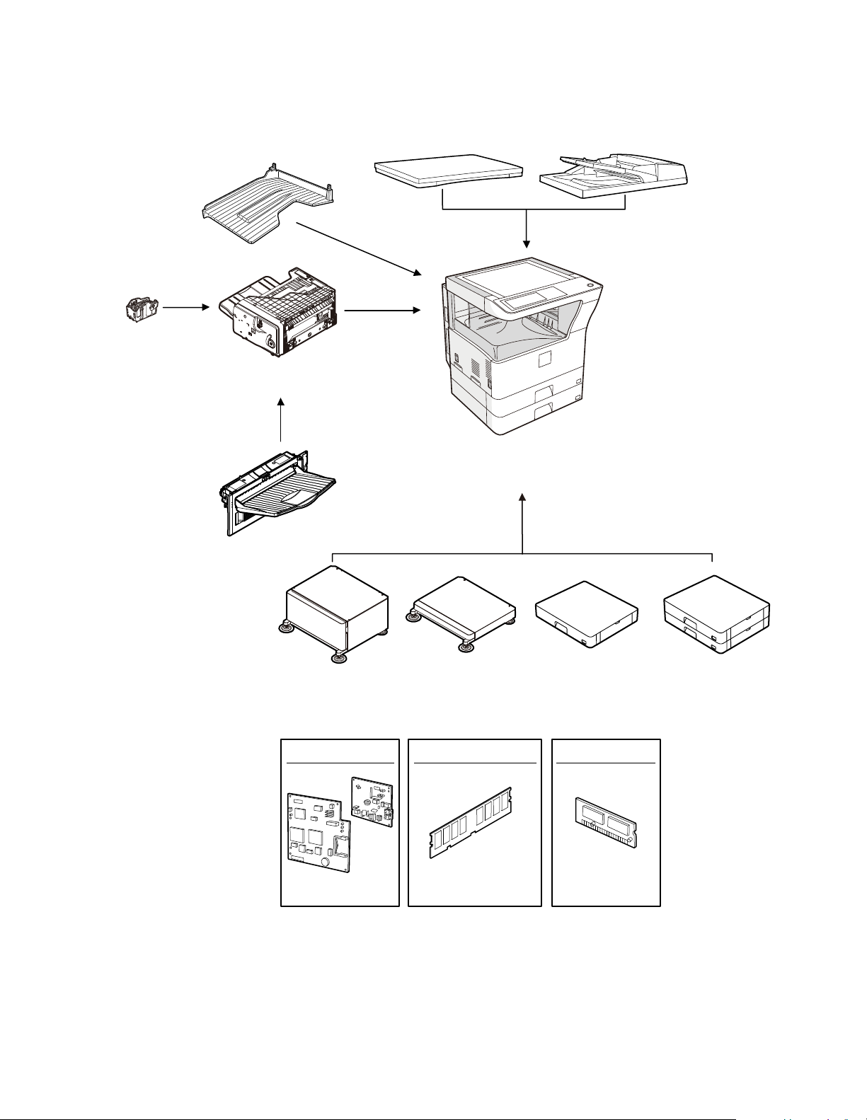
[1] PRODUCT OUTLINE
Paper feed unit
(500x2 Sheets)
Paper feed unit
(500 Sheets)
Machine stand
(Small)
Machine stand
(Large)
Finisher
[MX-FN13]
Staple cartridge
[MX-SCX1]
Reversing single pass feeder
[MX-RP10]
Document cover
[MX-VR10]
Expantion memory board
[AR-SM5](256MB)
[AR-SM6](512MB)
FAX expantion kit FAX memory (8MB)
[AR-FX7]
[AR-MM9]
Copier/Printer (SPLC) model
[AR-5726/5731]
Job separator tray
[MX-TR11]
[MX-DE11][MX-DE10]
[MX-DS11] [MX-DS12]
[MX-TE10]
Exit tray unit
Installation of the
MX-FN13 is required.
1. Line of machines and options
AR-5726/5731 PRODUCT OUTLINE 1 - 1
Page 5
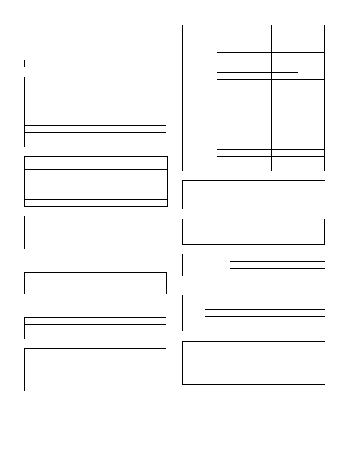
[2] SPECIFICATIONS
1. Basic function
A. Base engine
(1) Type
Type Desktop
(2) Engine composition
Photoconductor kind OPC drum (Drum dia. 30mm)
Copying method Electronic photo (Laser)
Developing system Dry, 2-component magnetic brush
Charging system Sawtooth charging
Transfer system Transfer roller system
Cleaning system Contact blade system
Fusing system Heat roller
Toner supply method Toner supply by front cover open
Waste toner disposal Toner car tridge collection
(3) Dimensions / Weight
External dimensions
(W x D x H)
Occupied
dimensions (W x D)
(when the manual
paper feed tray is
extended)
Weight About 46kg
(4) Warmup
Warm-up time 23 sec or less (26-sheet model)
Pre-heat Yes
Jam recovery time About 10sec, excluding fusing warmup, toner
Conditions: Leaving for 60 sec after door open, standard conditions,
polygon stop.
(5) First copy time
Platen 4.8 sec 4.5 sec
RSPF 9.3 sec or less
∗ Measuring conditions: When paper of A4 or 8.5” x 11” is fed from the
machine tray, with the polygon rotating.
(6) Engine resolution
Writing resolution 600 x 600dpi
Smoothing (Print) 1200dpi (equivalent) x 600dpi
Gradation Writing: Binary
(7) Printable range
Max. print size AB series: 416 x 293mm
Void area image loss Front/Rear: Less than 4mm
development
OC model: 623 x 628 x 668mm
RSPF model: 623 x 628 x 788mm
898 x 628mm
25 sec or less (31-sheet model)
control, etc.
26-sheet model 31-sheet model
(600dpi: 9826dot x 6920dot)
Inch series: 428 x 275mm
(600dpi: 10110dot x 6496dot)
Right/Left total: Less than 6mm at actual
(100%) size
(8) Engine speed (ppm)
Tray Paper size
Tray 1 - 4 A3 15 17
B4/8.5 x 13 17 20
A4/B5/A5/8.5 x 11/
5.5 x 8.5/16K
A4R/8.5 x 11R/16KR 18 24
B5R 21
11 x 17 14 17
8.5 x 14 16 20
8K 19
Manual paper
feed
A3 14 17
8.5 x 13 17 20
B4 16 19
A4/B5/A5/8.5 x 11/
5.5 x 8.5/16K
A4R/8.5 x 11R 19 22
16KR 23
B5R 21 24
11 x 17 14 16
8.5 x 14 16 19
26-sheet
model
26 31
23 27
31-sheet
(9) Power source
Voltage/Current 220 - 240V 8A
Frequency 50/60Hz
Power source code Inlet type
Power switch 1 power source
(10) Power consumption
Maximum rated
power consumption
Shift time to sleep
mode
1.45kw
Default (1 minute)
(11) Memory
Local Memory Standard 32MB
Expansion 512MB x 2
Max. 1056MB
B. Controller board
(1) Controller board
SPLC board
Interface Ethernet No
USB 2.0 Device Full Speed 1slot
Memory No
Memory expansion slot ---
C. Operation panel
Type Dot matrix LCD, touch panel
Size Monochrome H-VGA 8.1”
Display dot number 640 x 240 (H-VGA)
LCD drive display area 192 x 72mm
LCD backlight Fluorescent lamp backlight system
LCD contrast adjustment Yes
model
AR-5726/5731 SPECIFICATIONS 2 - 1
Page 6
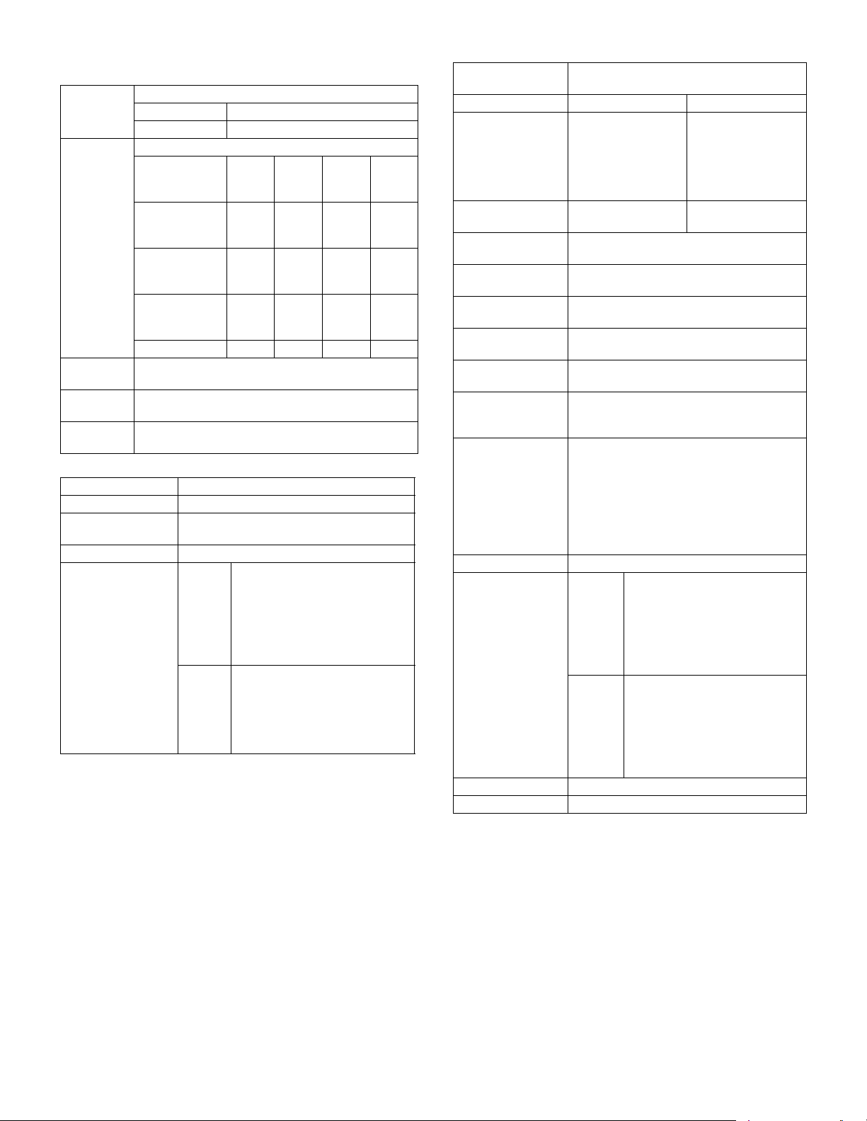
D. Scanner section
(1) Resolution/Gradation
Reading
resolution
(dpi)
Transmission
resolusion
(dpi)
Reading
gradation
Exposure
lamp
Output
gradation
Platen 400 x 600dpi
RSPF 400 x 600dpi
Select mode Normal
Input resolution:OC203.2
Input resolution:
RSPF
Transmission
resolution
Half tone No Yes Yes Yes
256 gradations
Electrodeless xenon lamp
Binary
(2) Document table
Type Document table fixed type (Flat bed)
Scanning area 297 x 431.8mm
Original standard
position
Detection Yes
Detection size Inch
Left bottom reference
series
AB
series
Copy mode
FAX transmission mode
Fine
text
203.2
x
293.4
203.2
293.4
203.2
97.8
Automatic setting
11 x 17, 8.5 x 14, 8.5 x 11,
8.5 x 11R, 5.5 x 8.5
Manual setting
11 x 17, 8.5 x 14, 8.5 x 13 (216 x
330), 8.5 x 11, 8.5 x 11R,
5.5 x 8.5, A3, A4, A4R
Automatic setting
A3, B4, A4, A4R, A5
Manual setting
11 x 17, 8.5 x 14, 8.5 x 13 (216 x
330), 8.5 x 11, 8.5 x 11R, A3, B4,
A4, A4R, A5
293.4
203.2
x
293.4
203.2
x
195.6
text
x
x
x
Super
fine
text
203.2
391.2
203.2
391.2
203.2
391
(3) Automatic document feeder
Ty pe R S PF
(Automatic duplex document feeder unit)
Scan speed When in single copy When in duplex copy
Copy 31-sheet model:
Ultra
fine
text
406.4
x
x
x
x
586.7
406.4
x
586.7
406.4
x
391
Fax 40 sheets/min
Document set
direction
Document standard
position
Document transport
system
Document size AB series: A3 - A5
Document weight Single face: 35 - 128g/m
Max. loading
capacity of
documents
Transport disable
document
Detection Yes
Detection size Inch
Multi copy S-S, S-D, D-D, D-S
Mixed paper feed Enable (Same width only)
27 sheets/min
(400 x 600dpi)
26-sheet model:
26 sheets/min
(400 x 600dpi)
(Normal text, A4R)
Face-up reference
Center reference
Sheet through system
Inch series: 11 x 17 - 5.5 x 8.5
Duplex: 52 - 105g/m
100 sheets (90g/m
Paper thickness of 13mm or less can be set.
OHP, perforated documents, photo,
catalogue, second original sheet, tracing
paper, carbon paper, heat-sensitive paper,
wrinkled paper, folded or broken paper,
pasted or cut-away paper, documents of
many perforated holes (2-hole, 3-hole
documents can be used), document printed
by an ink ribbon
Automatic setting
series
AB
series
11 x 17, 8.5 x 14, 8.5 x 11,
8.5 x 11R, 5.5 x 8.5, A3, A4
Manual setting
11 x 17, 8.5 x 14, 8.5 x 13 (216 x
330), 8.5 x 11, 8.5 x 11R,
5.5 x 8.5, A3, A4, A4R
Automatic setting
11 x 17, 8.5 x 11, A3, B4, A4,
A4R, B5, B5R, A5
Manual setting
11 x 17, 8.5 x 14, 8.5 x 13 (216 x
330), 8.5 x 11, 8.5 x 11R, A3, B4,
A4, A4R, A5
31-sheet model:
13.6 side/min
(400 x 600dpi)
26-sheet model:
13.6 side/min
(400 x 600dpi)
17 sheets/min
(Normal text, A4R)
2
, 9 - 34 lbs,
2
, 13.9 - 28 lbs
2
)
AR-5726/5731 SPECIFICATIONS 2 - 2
Page 7
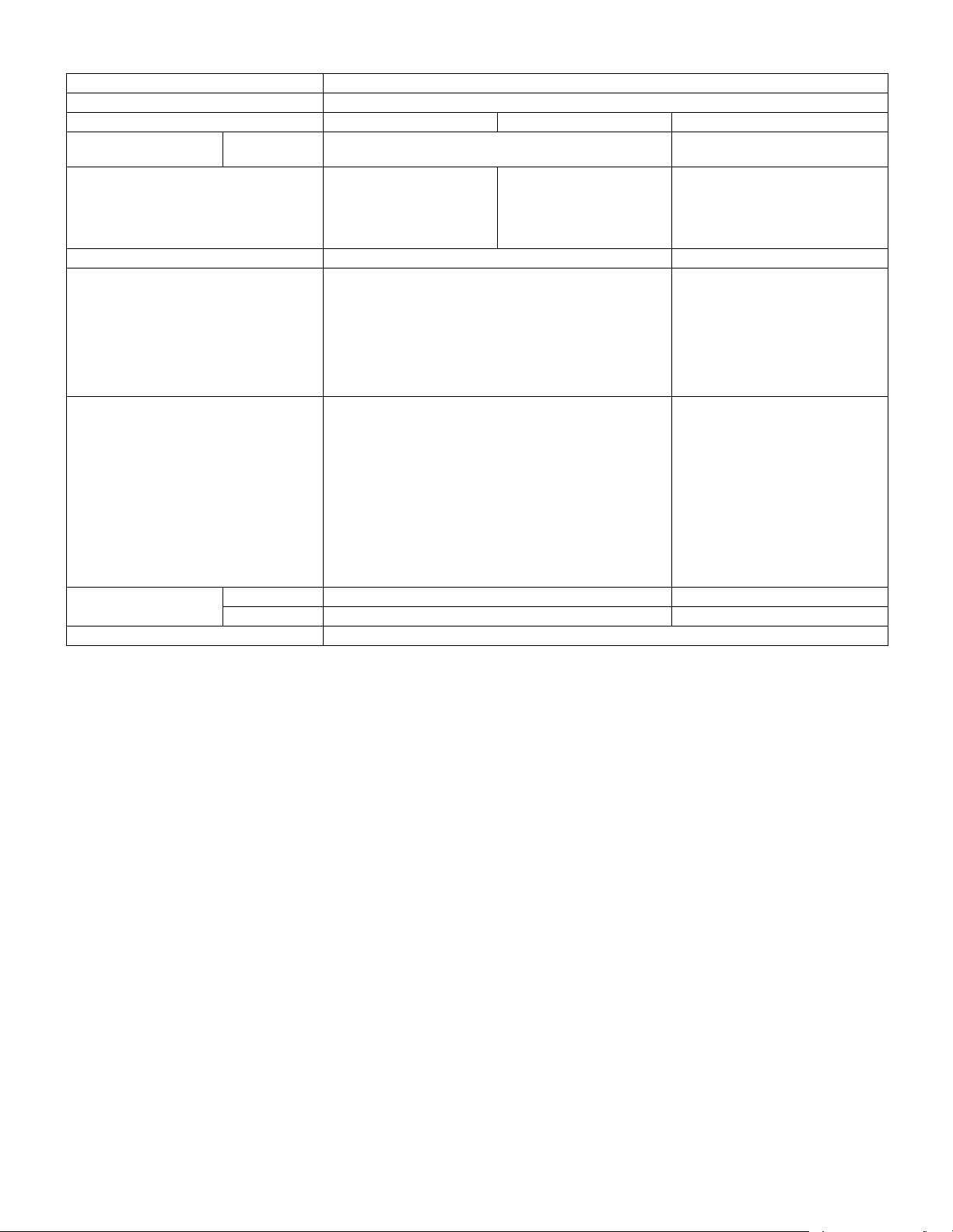
E. Paper feed section
Type Paper feed tray + Multi manual paper feed (Expanded up to 4 trays by installing options.)
Paper feed method Paper is fed from the above by the front loading system.
Details of paper feed section Tray1 Tray2 Manual paper feed tray
Paper capacity Standard paper
(80g/m
2
)
Paper size A3, B4, A4, A4R, B5, B5R,
A5, 11 x 17, 8.5 x 14,
8.5 x 13, 8.5 x 11, 8.5x11R,
5.5 x 8.5, 8K, 16K, 16KR
Paper size detection No Yes
2
Allowable paper type and weight for paper
56 - 105g/m
/15 - 28lbs Bond Multi paper feed:
feed
Paper type Standard paper (56 - 80g/m
Normal paper (60 - 105g/m
Letterhead
Color paper
Paper size setting when
shipping
Inch series 8.5 x 11 ---
AB series A4 ---
Paper remaining detection No (paper presence only)
∗ 1: Supported envelope kinds: Commercial10 (4 - 1/8” x 9 - 1/2”), International DL (110mm x 220mm), International C5 (162mm x 229mm)
500 sheets 100 sheets
A3, B4, A4, A4R, B5R,
11 x 17, 8.5 x 14 (216 x 356),
8.5 x 13 (216 x 330),
8.5 x 11, 8.5 x 11R, 8K, 16KR
A3, B4, A4, A4R, B5, B5R, A5R, A5,
B6R, 11 x 17, 8.5 x 14 (216 x 356),
8.5 x 13 (216 x 330), 8.5 x 11,
8.5 x 11R, 7.25 x 10.5R, 5.5 x 8.5,
8K, 16K, 16KR, A6R, Envelope*
Standard paper (56 - 128g/m
Special paper, heavy paper (max.
2
200g/m
)
Single paper feed:
Standard paper, special paper,
second original, heavy paper (max.
2
2
)
2
)
• Standard paper: 100 sheets
200g/m
), 56- 200g/m2 (14 - 54lbs)
(56 - 80g/m2)
• Recycled paper/coarse paper:
100 sheets
• Heavy paper (max. 200g/m
30 sheets
• OHP/Label sheet/gift wrapping
paper: 40 sheets
• Label sheet: 40 sheets
• Envelope (AB series: 10 sheets,
Inch series: 5 sheets)
1
2
)
2
):
AR-5726/5731 SPECIFICATIONS 2 - 3
Page 8
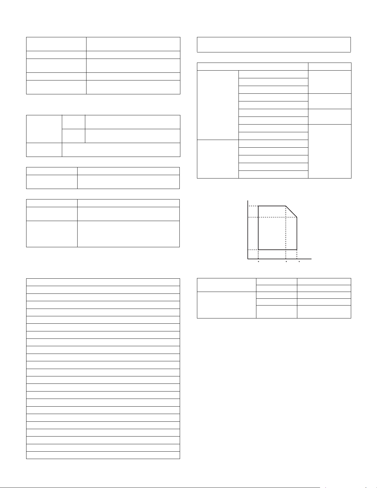
(Humidity)
85%
60%
20%
10 C 30 C 35 C
(Temperature)
F. Paper exit section
(1) Center tray of main unit
Paper exit position/
system
Paper exit capacity 500 sheets (A4, 8.5 x 11, 80g/m
Paper exit paper size/
kind
Shifter function Yes
Paper remaining
detection for paper exit
Main unit top surface face-down paper
exit
All kinds of paper which can be fed
Ye s
2
paper)
G. Copy functions
(1) Copy magnification ratio
Copy
magnification
ratio
Zoom 25 - 400%
(2) Density/copy image quality process
Exposure mode Binary: Automatic, Text, Text/Photo, Photo
Number of manual
steps
(3) Duplex
System Switchback system
Paper size A3, B4, A4, A4R, B5, B5R, A5, 11 x 17,
Type and weight of
paper which can be
passed
∗ When duplex printing is continued in a certain level of temperature,
the printing speed may be reduced in order to prevent an abnormal
temperature rise in the machine.
(4) Copy functions
Automatic paper selection
Automatic magnification ratio selection
Vertical/horizontal independent magnification ratio
Paper type selection
Auto tray switching
Rotation copy
Electronic sort
Job reservation (only during warm-up)
Program call-out/registration (10 items)
Preheat function
Auto power shut off function
User management (100 items)
Mixed documents feed (MIX only)
Binding margin (Left/Right/Upper)
Edge erase/Center erase (Center/Edge/Center + Edge)
1 set 2 copy
Cover paper/Insert paper (Cover/Back cover only)
Multi shot (2 in 1/4 in 1) (Centering available)
Card shot (Centering available)
Pamphlet mode (Centering available)
Duplex copy direction switching
Large volume document mode
Black/white reverse (except for UK)
Stream feeding mode (ON/OFF switch by the system setting)
AB
series
Inch
series
(Restriction by the document feeder unit: 50 - 200%)
25%, 50%, 70%, 81%, 86%, 100%,
115%, 122%, 141%, 200%, 400%
25%, 50%, 64%, 77%, 100%, 121%,
129%, 200%, 400%
5 steps
8.5 x 14, 8.5 x 13, 8.5 x 11, 8.5 x 11R
56 - 105g/m
Duplex print from manual paper feed can be
made. (Except for heavy paper, OHP sheet,
and other special paper)
2
/15 - 21.3 lbs Bond
H. Printer function
(1) Platform
•IBM PC/AT
•Macintosh
(2) Support OS
OS SPLC
Windows 2000
XP x64
Server 2003
Server 2003 x64
Vista
Vista x64
Server 2008
Server 2008 x64
Mac 9.0 - 9.2.2
X 10.2.8
X 10.3.9
X 10.4.11
X 10.5 - 10.5.6
I. Environmental conditions
Standard environmental
conditions
Usage environmental
conditions
Temperature 20 - 25°C
Humidity 65 ± 5%RH
Temperature 10 - 35°C
Humidity 20 - 85%RH
Atmospheric
pressure
Ye sXP
No
Ye s
No
590 - 1013 hPa
(height: 0 - 2000m)
AR-5726/5731 SPECIFICATIONS 2 - 4
Page 9

[3] CONSUMABLE PARTS
1. Supply system table
A. East Europe/Russia
No. Item Content Life Model name Remarks
1 Toner cartridge
(black)
2 Developer (black) Developer
3 Drum Drum ×1 26cpm: 75K
B. Asia Subsidiaries
No. Item Content Life Model name Remarks
1 Toner cartridge
(black)
2 Developer (black) Developer
3 Drum Drum ×1 26cpm: 75K
C. SMEF/Agent
No. Item Content Life Model name Remarks
1 Toner cartridge
(black)
2 Developer (black) Developer
3 Drum Drum ×1 26cpm: 75K
Toner cartridge (With IC chip)
(Toner; Net 700g)
(Developer; Net 300g)
Toner cartridge (With IC chip)
(Toner; Net 700g)
(Developer; Net 300g)
Toner cartridge (With IC chip)
(Toner; Net 700g)
(Developer; Net 300g)
×1 33K MX-312GT Life setting by A4 (8.5"×11") 6% document
Default: Toner save mode
×1 26cpm: 75K
31cpm: 100K
31cpm: 100K
×1 33K MX-312AT Life setting by A4 (8.5"×11") 6% document
×1 26cpm: 75K
31cpm: 100K
31cpm: 100K
×1 33K MX-312FT Life setting by A4 (8.5"×11") 6% document
×1 26cpm: 75K
31cpm: 100K
31cpm: 100K
MX-312GV
MX-312GR
Default: Toner save mode
MX-312AV
MX-312AR
Default: Toner save mode
MX-312FV
MX-312FR
AR-5726/5731 CONSUMABLE PARTS 3 - 1
Page 10
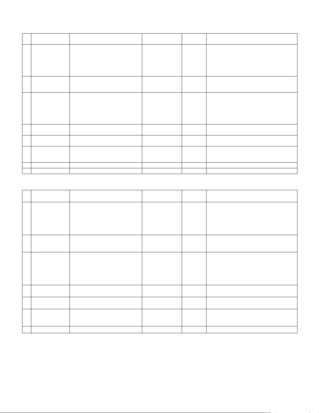
2. Maintenance parts list
A. East Europe/Russia/SMEF
No. Item Content Life
1 Upper heat roller kit Upper heat roller
Fuser gear
Upper heat roller bearing
Upper cleaning pad
Fusing separation pawl (upper)
Thermistor cleaning pad
2 Lower heat roller kit Lower heat roller
Fusing separation pawl (lower)
Fuser bearing (lower)
3 150K PM kit Drum separation pawl unit
Transfer roller unit
DV blade
DV side sheet F
DV side sheet R
Toner filter unit
4 MC unit MC unit ×10 26cpm: 75K (×10)
5 Cleaner blade Cleaner blade ×10 26cpm: 75K (×10)
6 Drum frame unit Drum frame unit ×1 26cpm: 225K
7 Transfer roller unit Transfer roller unit ×1 150K MX-311TX
8 Staple cartridge Staple cartridge ×3 5000 staples ×3 MX-SCX1
∗ The other maintenance parts than the above are supplied as service parts.
×1
×1
×2
×1
×4
×2
×1
×4
×2
×2
×1
×1
×1
×1
×1
150K AR-310UH
300K MX-311LH
150K MX-311KA
31cpm: 100K (×10)
31cpm: 100K (×10)
31cpm: 300K
B. Asia Subsidiaries/Agent
No. Item Content Life
1 Upper heat roller kit Upper heat roller
Fuser gear
Upper heat roller bearing
Upper cleaning pad
Fusing separation pawl (upper)
Thermistor cleaning pad
2 Lower heat roller kit Lower heat roller
Fusing separation pawl (lower)
Fuser bearing (lower)
3 150K PM kit Drum separation pawl unit
Transfer roller unit
DV blade
DV side sheet F
DV side sheet R
Toner filter unit
4 MC unit MC unit ×10 26cpm: 75K (×10)
5 Cleaner blade Cleaner blade ×10 26cpm: 75K (×10)
6 Drum frame unit Drum frame unit ×1 26cpm: 225K
7 Staple cartridge Staple cartridge ×3 5000 staples ×3 MX-SCX1
∗ The other maintenance parts than the above are supplied as service parts.
×1
×1
×2
×1
×4
×2
×1
×4
×2
×2
×1
×1
×1
×1
×1
150K AR-310UH
300K MX-311LH
150K MX-311KA
31cpm: 100K (×10)
31cpm: 100K (×10)
31cpm: 300K
Model
name
MX-311MC
MX-311CB
MX-311DU
Model
name
MX-311MC
MX-311CB
MX-311DU
Remarks
∗ The life of the toner reception seat attached to
the drum frame is 300K, and it can be used up
to 3 times. (Supplied as a drum frame unit.)
Remarks
∗ The life of the toner reception seat attached to
the drum frame is 300K, and it can be used up
to 3 times. (Supplied as a drum frame unit.)
AR-5726/5731 CONSUMABLE PARTS 3 - 2
Page 11
3. Developer/Drum life end definition
(Humidity)
85%
60%
20%
10 C 30 C 35 C
(Temperature)
When the developer/drum counter reaches the specified level.
When the developer/drum rpm reaches the specified level.
When either of the above reached the specified level, it is judged as life end.
In an actual case, when correction or warm-up operation is performed as well as output operation, the developer and the drum rotates.
Therefore, the developer/drum consuming level cannot be determined only by the copy/print quantity. When, therefore, the rpm reaches the specified
level, it is judged as life end.
To check the drum and developer life, use SIM22-1.
Developer/drum counter
Developer/drum 26cpm model 31cpm model 550K
75K 100K
Number of rotations
(Rotations)
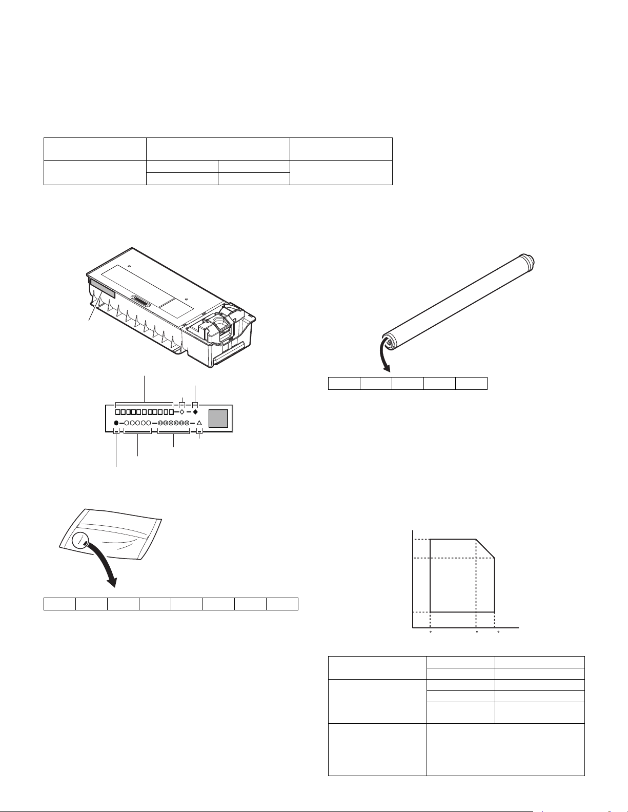
4. Production number identification
<Toner cartridge>
The label on the toner cartridge shows the date of production.
Label position
Internal product name
Incompatibility
Destination
Version No.
Production year/month/day (6 digits)
Serial No. in production day (5 digits)
Production place (1 digits)
<Developer>
<Drum>
The laser print indicates the model conformity code and the date (year,
month, day) of production.
1 Alphabet
2 Number
3 Number or X, Y, Z
4, 5 Number
5. Environment conditions
12345
Indicates the model conformity code. L for this model.
Indicates the end digit of the production year.
Indicates the month of packing.
X stands for October, Y November, and Z December.
Indicates the day of the month of packing.
12345678
The lot number is of 8 digits. Each digit indicates the content as follows.
The number is printed on the right under side of the back surface of the
developer bag.
1 Alphabet
Indicates the production factory.
2 Number
Indicates the production year.
3, 4 Number
Indicates the production month.
5, 6 Number
Indicates the production day.
7 Hyphen
8 Number
Indicates the production lot.
AR-5726/5731 CONSUMABLE PARTS 3 - 3
Standard environmental
conditions
Usage environmental
conditions
Storage period Toner/Developer: 24 months from the
Temperature 20 - 25°C
Humidity 65 ± 5%RH
Temperature 10 - 35°C
Humidity 20 - 85%RH
Atmospheric
pressure
manufactured month (Production lot)
under unsealed state
Drum: 36 months from the manufactured
month under unsealed state
590 - 1013 hPa
(height: 0 - 2000m)
Page 12
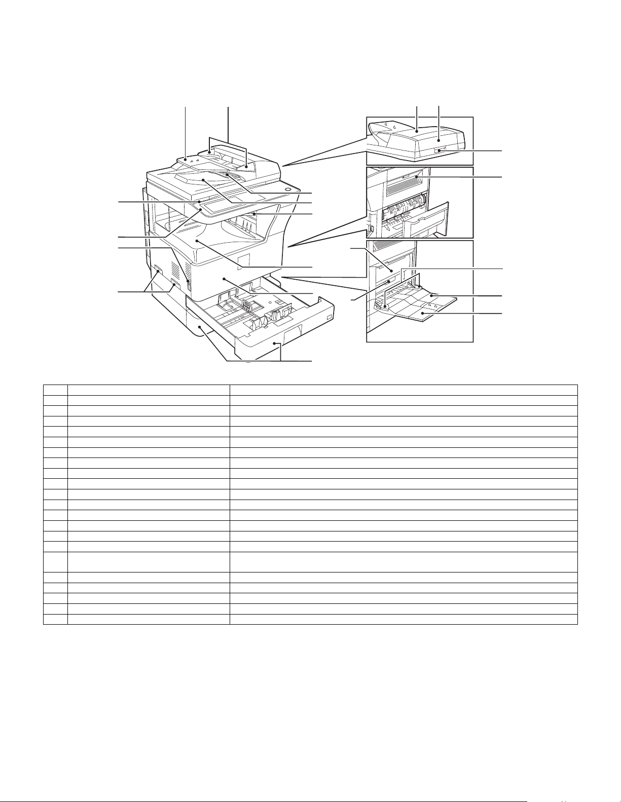
[4] EXTERNAL VIEW AND INTERNAL STRUCTURE
36
7
16
19
20
21
1
8
11
9
10
2
15
18
14
13
17
4
5
12
1. External view
No. Name Function/Operation
1 Document feeder tray Place the original(s) that you wish to scan face up here.
2 Original guides Adjust to the size of the originals.
3 Document feeder cover Open to remove misfed originals.
4 Reversing tray Pull out to remove misfed originals.
5 Exit area Originals exit the machine here after copying.
6 Document transport cover Open to remove misfed originals.
7 Document transport cover knob Pull to open the document transport cover.
8 Document glass Place an original that you wish to scan face down here.
9 Power switch Press to turn the machine power on and off.
10 Handles Use to move the machine.
11 Operation panel Contains operation keys and the touch panel.
12 Job separator tray (Upper tray) (optional) Print jobs and received faxes are delivered to this tray.
13 Center tray Finished copies are delivered to the center tray.
14 Front cover Open to remove paper misfeeds and perform machine maintenance.
15 Paper trays Each tray holds 500 sheets of copy paper.
16 Upper right side cover Open to remove misfeeds when an optional job separator tray kit or a optional finisher is
17 Side cover Open to remove misfeeds.
18 Side cover handle Pull to open the side cover.
19 Bypass tray paper guides Adjust to the width of the paper.
20 Bypass tray Regular paper and special paper (such as transparency film) can be fed from the bypass tray.
21 Bypass tray extension Pull out the bypass tray extension before placing paper in the bypass tray.
installed.
AR-5726/5731 EXTERNAL VIEW AND INTERNAL STRUCTURE 4 - 1
Page 13
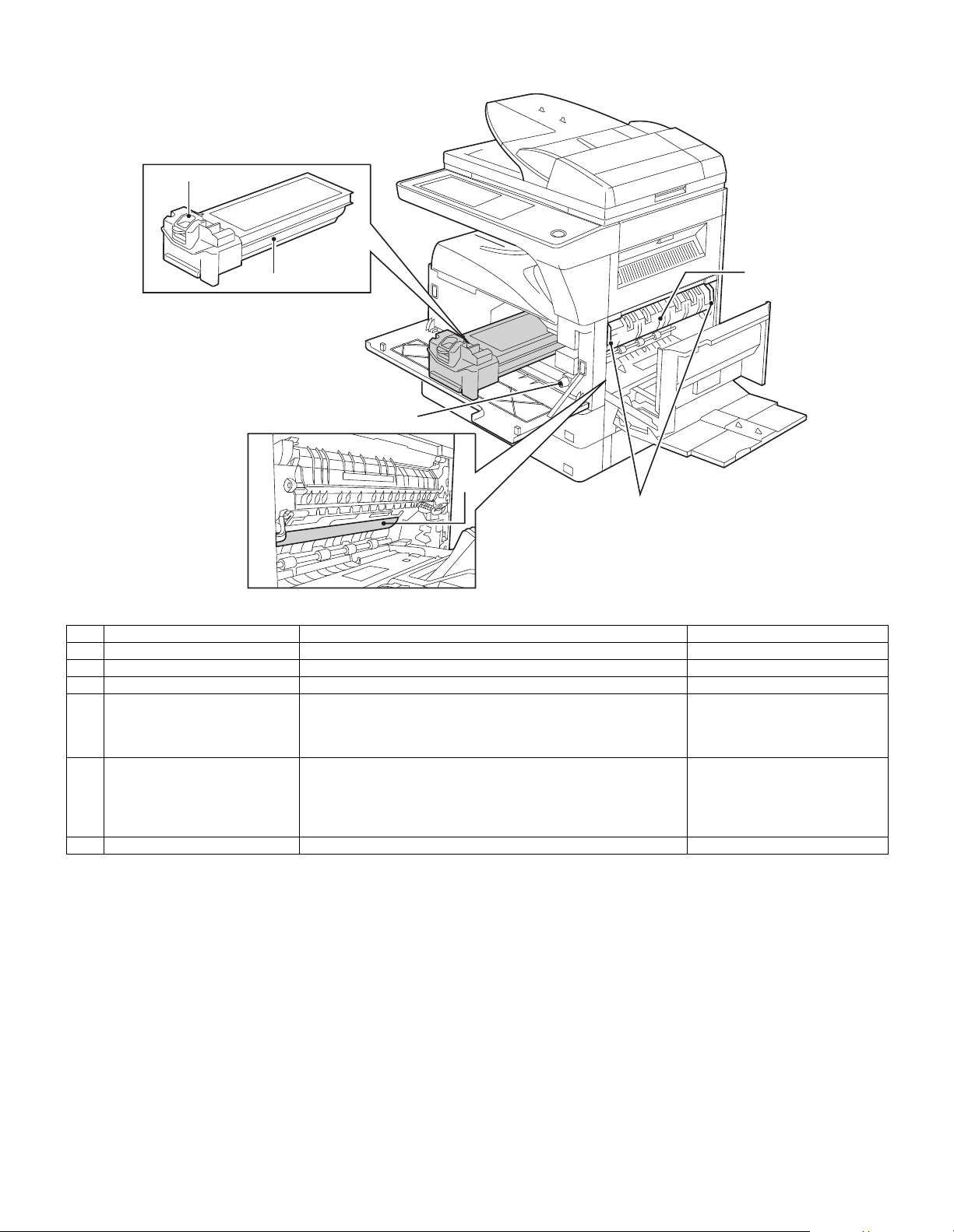
2. Internal structure
1
2
3
4
5
No. Name Function/Operation Note
1 Toner cartridge lock release lever Use to unlock the toner cartridge.
2 Toner cartridge Contains toner.
3 Roller rotating knob Turn to remove misfed paper.
4 Photoconductive drum Copy images are formed on the photoconductive drum. Do not touch the photoconductive
drum (green portion). Doing so
may damage the drum and cause
smudges on copies.
5 Fusing unit release levers To remove a paper misfeed in the fusing unit, push up on these
levers and remove the paper.
6 Fusing unit paper guide Open to remove misfed paper.
The fusing unit is hot.
Do not touch the fusing unit when
removing misfed paper.
Doing so may cause a burn or
injury.
6
AR-5726/5731 EXTERNAL VIEW AND INTERNAL STRUCTURE 4 - 2
Page 14
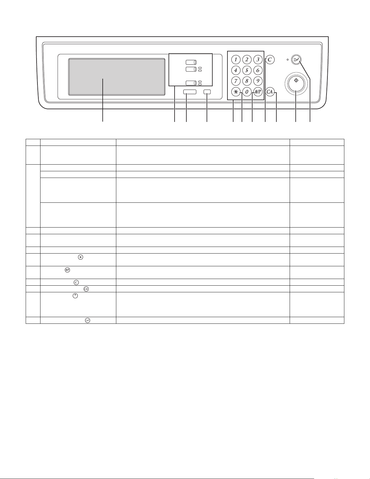
3. Operation panel
COPY
PRINT
FAX
JOB STATUS
ON LINE
DATA
LINE
DATA
SYSTEM SETTINGS
LOGOUT
12345678 91011
No. Name Function/Operation Note
1 Touch panel The machine status, messages and touch keys are displayed on the panel.
The display will show the status of printing, copying or network scanning
according to the mode that is selected. For details see the next page.
2 Mode select keys and indicators Use to change modes and the corresponding display on the touch panel.
[COPY] key Press to select copy mode.
[PRINT] key/ONLINE indicator/
DATA indicator
[PRINT] key: Press to select print mode.
• ONLINE indicator: Print jobs can be received when this indicator is lit.
• DATA indicator: A print job is in memory. The indicator lights steadily while
the job is held in memory, and blinks while the job is printed.
[FAX] key/LINE indicator/
DATA indicator
[FAX] key: Press to select fax mode when the fax option is installed.
• LINE indicator : This lights up while faxes are being sent or received.
When the fax option is
installed.
• DATA indicator: Blinks when a fax has been received to memory and lights
steadily when a fax is waiting in memory for transmission.
3 [JOB STATUS] key Press to display the current job status.
4 [SYSTEM SETTINGS] key Use to adjust various settings of the machine including the contrast of the touch
panel and administrator settings.
5 Numeric keys Use to enter numeric values for various settings.
6 [LOGOUT] key ( ) When auditing mode is enabled, press this key after finishing a job to return the
machine to account number entry standby.
7 [#/P] key ( ) Use this key to execute a job program in copy mode.
The key is also used to dial in fax mode.
8 [CLEAR] key ( ) Press to clear a copy number setting or cancel a job.
9 [CLEAR ALL] key ( ) Resets the settings to the initial settings.
10 [START] key ( ) Press in copy mode, scanner mode, or fax mode to begin copying, network
scanning, or faxing.
This key blinks when auto power shut mode has activated. Press the key to
return to normal operation.
11 [INTERRUPT] key ( ) Use to perform an interrupt copy job.
AR-5726/5731 EXTERNAL VIEW AND INTERNAL STRUCTURE 4 - 3
Page 15
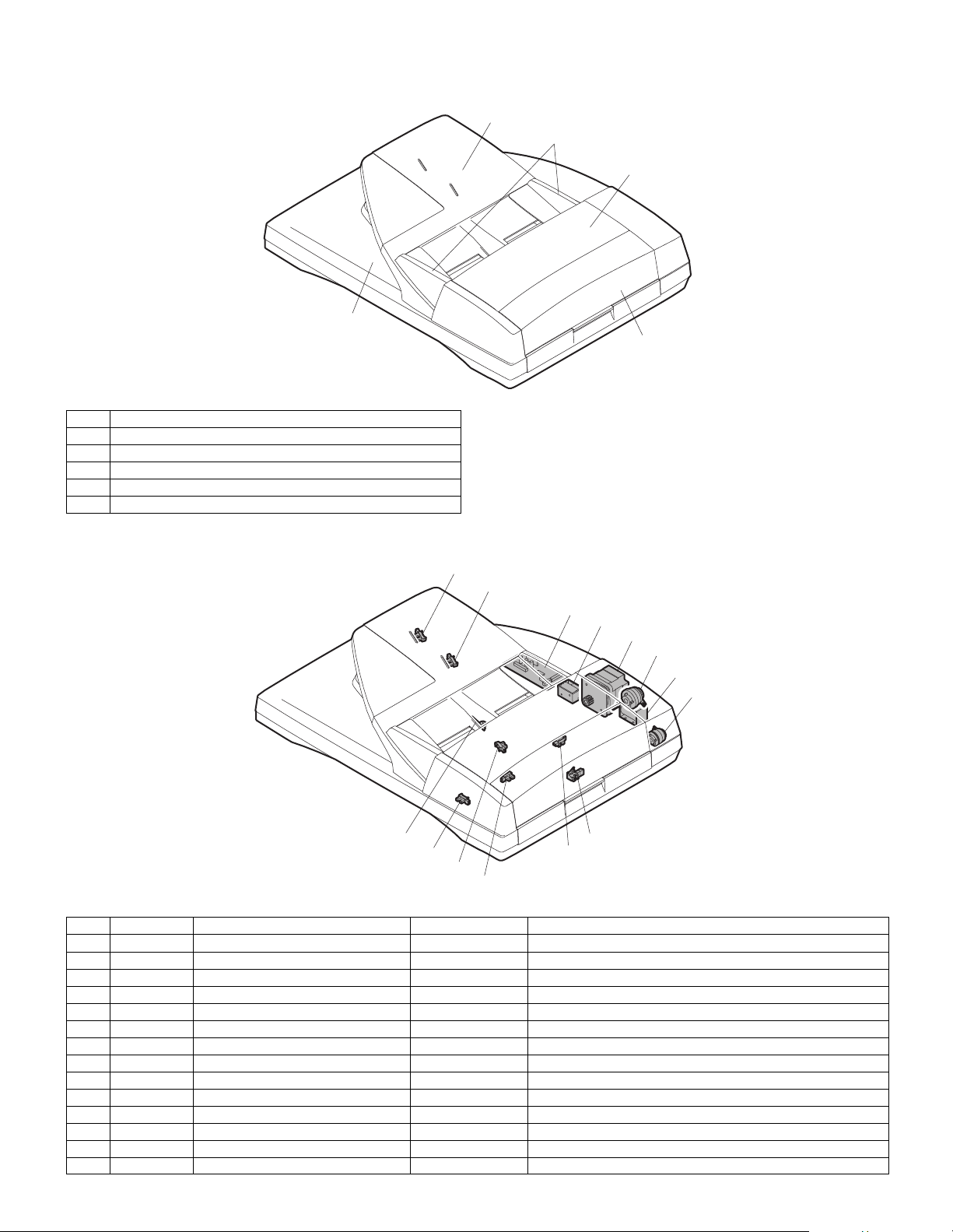
4. RSPF
A. External view
No. Name
1 Document set tray
2 Document guide
3 Document feed section cover
4 Document transport section cover
5 Document exit section
1
2
3
5
4
B. Internal structure
11
10
9
8
7
3
5
6
14
12
13
4
1
2
No. Code Name Type Function/Operation
1 EMPS Document set sensor Photo transmission Detects presence of documents.
2 FGOD Open/close sensor Photo transmission Detects open/close of the paper feed unit.
3 DFCL Paper feed clutch — —
4 DFD Paper entry sensor Photo transmission Detects presence of documents.
5 RSOL Pressure release solenoid — —
6 CLH Transport clutch — —
7 DTM SPF motor Stepping motor Drives document feed on the tray, transport, and paper exit roller.
8 GSOL Gate solenoid — —
9 — Interface PWB — —
10 DLS1 Document length detection SW (Short) Photo transmission Detects the document length on the tray.
11 DLS2 Document length detection SW (Long) Photo transmission Detects the document length on the tray.
12 OPCLS Book sensor Photo transmission Detects the SPF float.
13 RDD Paper exit sensor Photo transmission Detects presence of documents.
14 SWD Document width sensor Volume Detects the document width on the tray.
AR-5726/5731 EXTERNAL VIEW AND INTERNAL STRUCTURE 4 - 4
Page 16
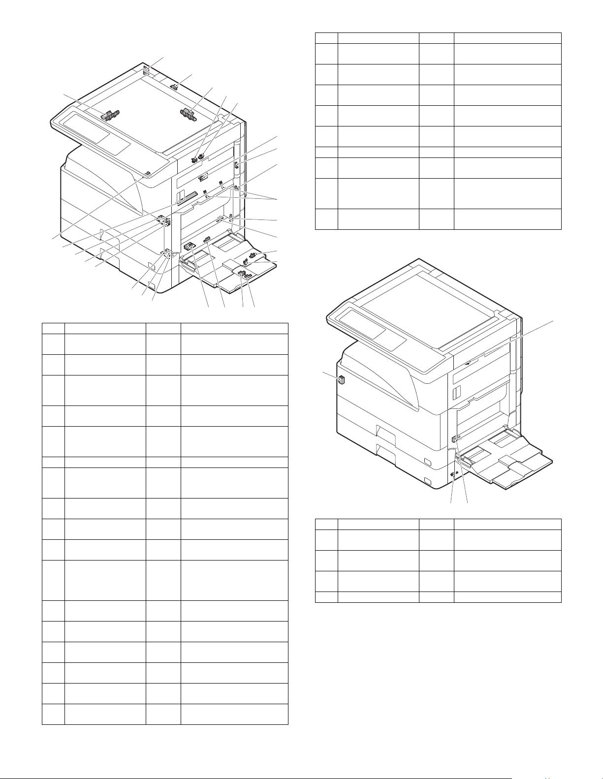
5. Sensor
1
2
25
24
23
22
21
20
19
18
17
No. Name Code Function and operation
1 Mirror home position
sensor
2 Document cover
sensor
3 Document size
sensor
4 2nd paper exit sensor
(Option)
5 2nd paper exit full
detection sensor
(Option)
6 1st paper exit sensor POD1 1st paper exit detection
7 Shifter home position
sensor (Except North
America)
8 Paper exit sensor
(DUP side)
9 Thermistor Fusing temperature
10 1st tray (paper tray)
detection
11 Manual feed paper
entry sensor
12 Manual paper feed
tray empty sensor 2
13 Manual paper feed
tray empty sensor 1
14 Manual feed length
detection sensor 1
15 Manual feed length
detection sensor 2
16 Manual feed paper
empty sensor
17 2nd tray paper pass
sensor
MHPS Mirror (scanner) home
OCSW Document cover open/close
DSIN3 Document size detection
POD2 2nd paper exit detection
TOPF 2nd paper exit section full
SFTHP Shifter home position sensor
PPD2 Paper exit detection
CD1 1st tray (paper tray) empty
PPD1L Sensor of paper entry from
MPLS2 Manual feed tray position
MPLS1 Manual feed tray position
MPLD1 Manual feed paper length
MPLD2 Manual feed paper length
MPED Manual feed paper empty
PFD2 2nd tray paper pass
3
4
5
14151626
position detection
detection
(Inch series: PD3, 4)
(AB series: PD4, 5)
detection
detection
detection
detection
the manual paper feed tray,
the 2nd/multi-tray desk, or
the DUP
detection
detection
detection
detection
detection
6
7
8
9
10
11
12
13
No. Name Code Function and operation
18 2nd tray paper upper
limit detection sensor
19 2nd tray paper empty
sensor
20 1st tray paper pass
sensor
21 1st tray paper upper
limit detection sensor
22 1st tray paper empty
sensor
23 Toner sensor Toner density detection
24 Center tray paper
YES/NO sensor
25 Document size sensor DSIN0 Document size detection
26 Reverse pass paper
detection sensor
LUD2 2nd tray paper upper limit
detection
PED2 2nd tray paper empty
detection
PPD1H 1st tray paper pass
LUD1 1st tray paper upper limit
detection
PED1 1st tray paper empty
detection
LOEMP Center tray paper YES/NO
DUP2
detection
(Inch series: PD1, 2)
(AB series: PD1 – 3)
Reverse pass detection
6. Switch
4
23
No. Name Code Function and operation
1 Right cabinet door
switch (Option)
2 Door switch DSWR1 Front door and side door
3 2nd right door switch DSWR2 Side door open/close
4 Main switch PSSW Main power switch
DSWR0 Right cabinet door open/
close detection
open/close detection
detection
1
AR-5726/5731 EXTERNAL VIEW AND INTERNAL STRUCTURE 4 - 5
Page 17
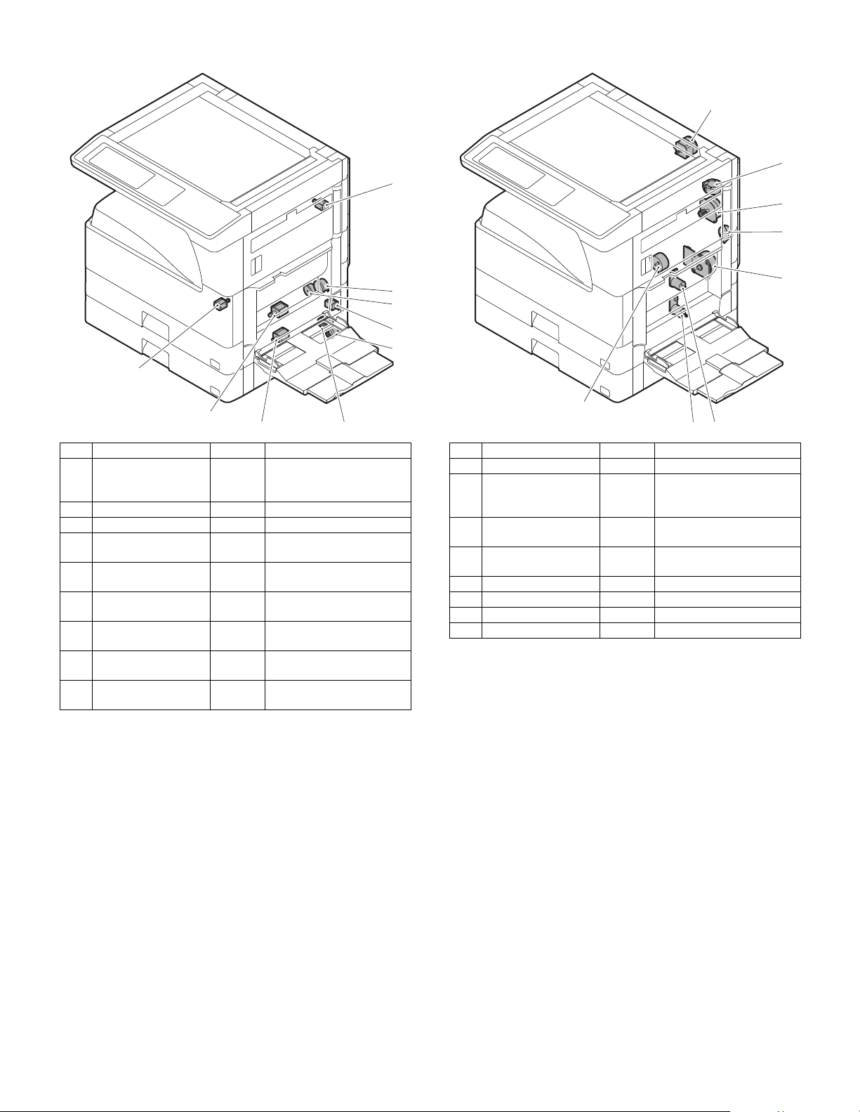
7. Solenoid/Clutch 8. Drive motor
1
2
3
4
5
6
7
8
9
1
2
4
5
6
7
8
9
No. Name Code Function and operation
1 Paper exit gate
switching solenoid
(Option)
2 PS clutch RRC Main unit paper feed
3 Paper feed clutch CPFS1 Paper feed roller drive
4 Manual paper feed
solenoid
5 Paper feed transfer
clutch
6 2nd tray paper feed
clutch
7 2nd tray paper feed
solenoid
8 Paper feed solenoid CPFC1 Solenoid for the paper feed
9 Separation pawl
solenoid
OGS Paper exit gate switcher
MPFS Manual paper feed
solenoid
TRC2 Paper feed transfer clutch
CPFS2
CPFC2 Solenoid for the paper feed
from the tray
from the tray
PSPS Separation pawl operation
solenoid
No. Name Code Function and operation
1 Mirror motor MIRM Optical mirror base drive
2 Shifter motor
(Except North
America)
4 Duplex motor DPXM Duplex paper switching
5 DUP-2 motor Reverse pass for paper
6 Main motor MM Main drive
7 Tray lift-up motor LUM1 Tray paper lift-up
8 Tray lift-up motor LUM2 Tray paper lift-up
9 Toner motor TM Toner supply
SFTM Shifter drive
and exit motor
transport
AR-5726/5731 EXTERNAL VIEW AND INTERNAL STRUCTURE 4 - 6
Page 18
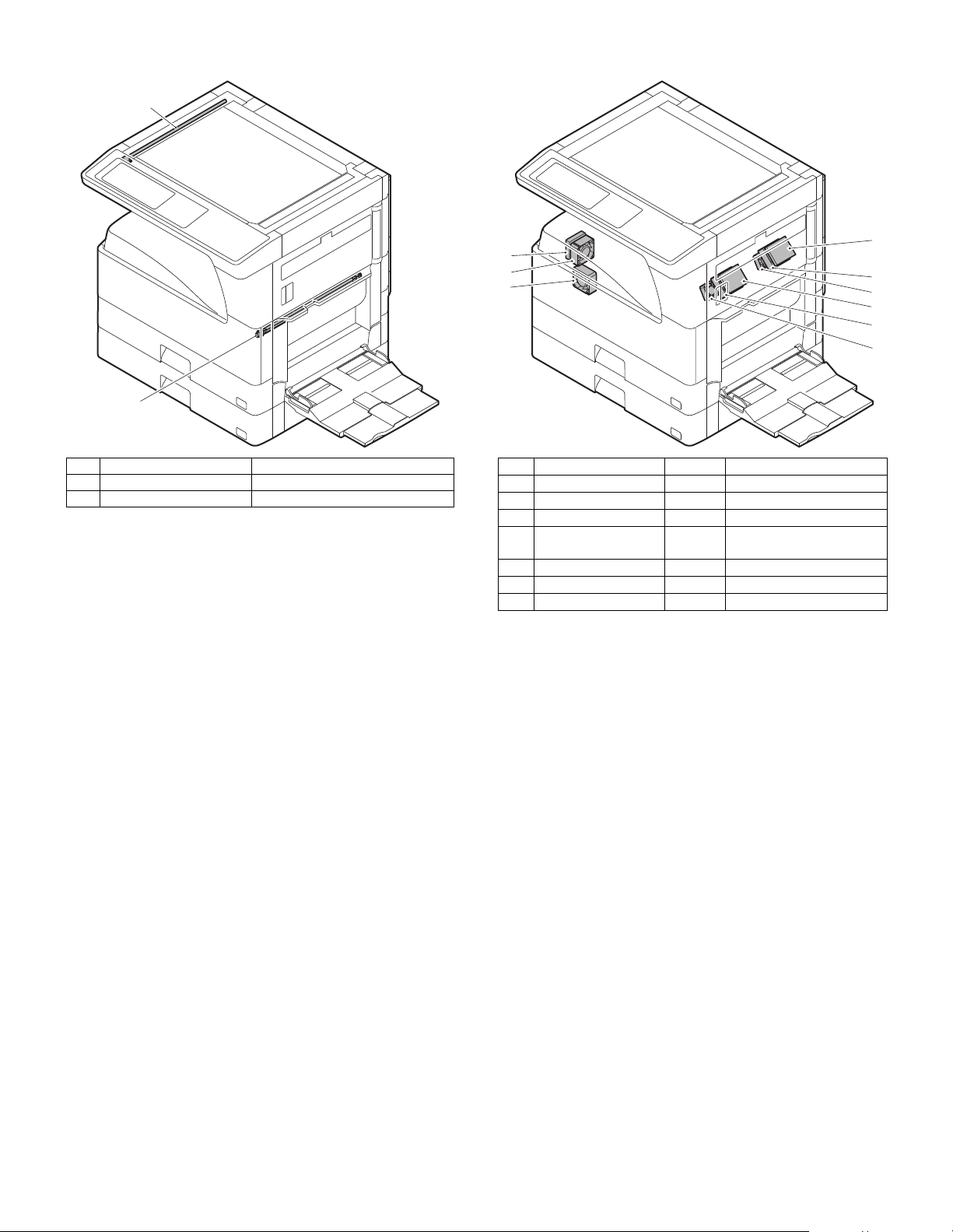
9. Lamp 10. Fan/Filter
2
1
4
6
1
1
2
3
7
5
6
No. Name Function and operation
1 Copy lamp Image radiation lamp
2 Heater lamp Fusing heat lamp
No. Name Code Function and operation
1 Cooling fan VFM Cools the inside of the unit.
2 Exhaust fan motor DCFM Cools the inside of the unit.
3 Intake fan motor DCFM2 Cools the inside of the unit.
4 Fusing paper exit fan VFM2 Cools the inside of the unit.
(31 sheet model)
5 Fusing paper exit fan VFM2 Cools the inside of the unit.
6 Ozon filter
7 Ozon filter
AR-5726/5731 EXTERNAL VIEW AND INTERNAL STRUCTURE 4 - 7
Page 19
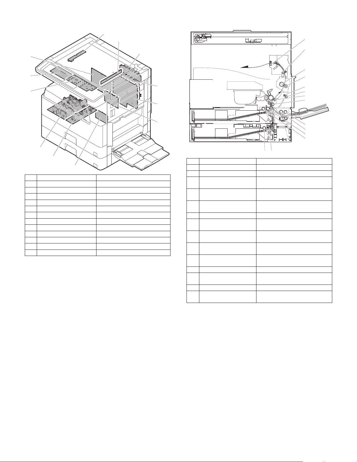
11. PWB 12. Roller
1
2
3
4
5
6
7
9
8
10
11
12
No. Name Function and operation
1 Paper exit roller Paper exit roller
No. Name Function and operation
1 Inverter PWB Copy lamp control
2 CCD PWB For image scanning (read)
3 Option connector PWB
4 IMC PWB Image process
5 MCU PWB Main unit control
6 Mother board Connection with FAX PWB
7 Tray interface PWB 2nd tray control
8 DC power supply PWB DC voltage control
9 High voltage PWB High voltage control
10 KEY PWB
11 OPU PWB Operation panel control
12 SPLC PWB Output image signal
2 Transport roller Paper transport roller
3 Upper heat roller Fuses toner on paper.
4 Lower heat roller Fuses toner on paper.
5 DUP transport follower
roller
6 DUP transport roller Duplex paper transport
7 Transport roller Transfer images on the drum onto
8 Resist roller Synchronize the paper lead edge
9 Manual paper feed roller Picks up papers in manual paper
10 Manual feed transport
roller
11 1st tray pick-up roller Picks up paper from the tray.
12 1st tray paper feed roller Transports the picked up paper to
13 2nd tray pick-up roller Picks up paper from the tray.
14 2nd tray paper feed roller Transports the picked up paper to
1
2
3
4
5
6
7
8
9
10
11
12
1314
(with the Teflon roller)
(with the silicone rubber roller)
Duplex paper transport
paper.
with the image lead edge.
feed port.
Transports paper from the manual
paper feed port.
RESIST section.
RESIST section.
AR-5726/5731 EXTERNAL VIEW AND INTERNAL STRUCTURE 4 - 8
Page 20
[5] ADJUSTMENTS
1. Adjustment item list
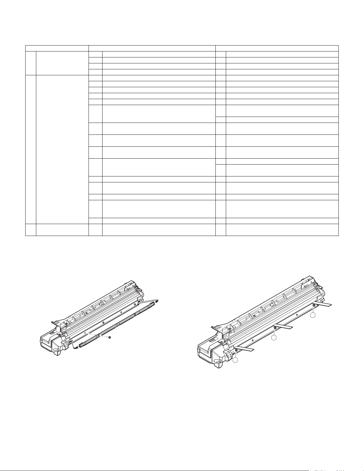
A Process section (1) Developing doctor gap adjustment Developing doctor gap adjustment
B Mechanism section (1) Print start position adjustment SIM50-5
C Image density
Section Adjustment item Adjustment procedure/SIM No.
(2) MG roller main pole position adjustment MG roller main pole position adjustment
(3) Developing bias voltage adjustment SIM8-1
(4) Grid bias voltage adjustment SIM8-2
(2) RSPF image lead edge position adjustment SIM50-6
(3) Rear edge void adjustment SIM50-1
(4) Paper off center adjustment SIM50-10
(5) Left edge void area adjustment SIM50-1-8
(6) Main scanning direction (FR direction) distortion
balance adjustment
(7) Sub scanning direction (scanning direction)
distortion adjustment
(8) Main scanning direction (FR direction) distortion
balance adjustment
(9) Main scanning direction (FR direction)
magnification ratio adjustment
(10) Sub scanning direction (scanning direction)
magnification ratio adjustment
(11) Off center adjustment (RSPF mode) SIM50-12
(12) OC (RSPF) open/close detection position
adjustment
(13) Original sensor adjustment SIM41-2, 41-4 (41-1)
(14) RSPF white correction pixel position adjustment
(required in an RSPF model when replacing the
lens unit)
(15) RSPF scan position auto adjustment SIM53-8
(1) Copy mode SIM46-2
(exposure) adjustment
No. 2/3 mirror base unit installing position
adjustment
Copy lamp unit installing position adjustment
Winding pulley position adjustment
Rail height adjustment
SIM48-1-1
a OC mode in copying (SIM 48-1-2)
b RSPF sub scanning direction magnification ratio
(SIM48-1-3, 48-1-4)
SIM41-3
SIM63-7
2. Details of adjustment
A. Process section
(1) Developing doctor gap adjustment
1) Remove the doctor cover.
2) Loosen the developing doctor fixing screw A.
3) Insert a thickness gauge of 1.5mm to the positions of three screws
on the developing docter as shown.
R
A
C
A
F
A
4) Tighten the developing doctor fixing screw.
5) Check the clearance of the developing doctor. If it is within the
specified range, then fix the doctor fixing screw with screw lock.
∗ When inserting a thickness gauge, be careful not to scratch the
developing doctor and the MG roller.
<Adjustment specification>
Developing doctor gap
F/C/R: 1.5
+0.1mm
-0.15mm
AR-5726/5731 ADJUSTMENTS 5 - 1
Page 21
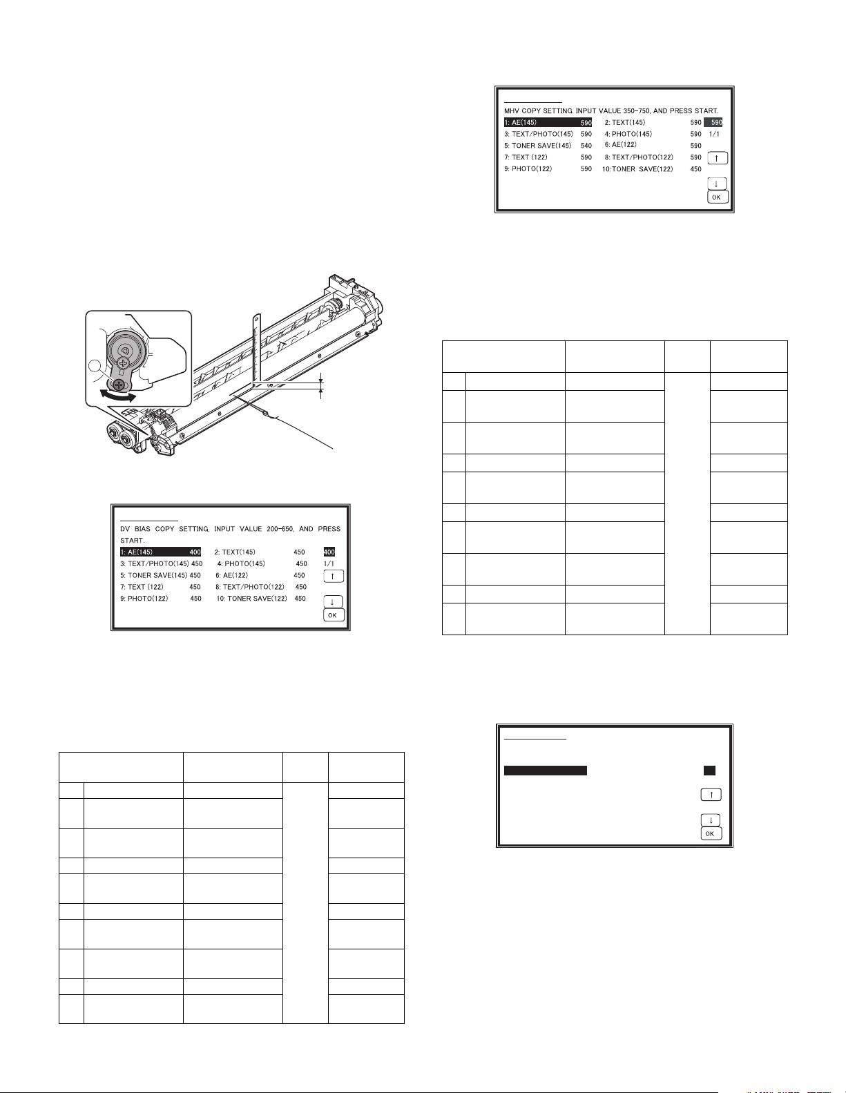
(2) MG roller main pole position adjustment
9.1mm
A
SIMULATION 8-1
426
1/1
DV BIAS COPY SETTING. INPUT VALUE 200-550, AND PRESS
START.
1: AE 426
2: TEXT 450
3: TEXT/PHOTO 450
4: PHOTO 450
5: SUPER/PHOTO 400
6: TONER SAVE 376
SIMULATION 8-1
SIMULATION 8-2
SIMULATION 50-5
53
1/1
LEAD EDGE ADJUSTMENT(PRINT). INPUT VALUE 0-99, AND PRESS
START.
1: TRAY1 53
2: OPTION 53
3: MANUAL 53
4: DUPLEX 53
1) Put the developing unit on a flat surface.
2) Tie a needle or pin on a string.
3) Hold the string and bring the needle close to the MG roller horizontally. (Do not use paper clip, which is too heavy to make a correct
adjustment.) (Put the developing unit horizontally for this adjustment.)
4) Do not bring the needle into contact with the MG roller, but bring it
to a position 2 or 3mm apart from the MG roller. Mark the point on
the MG roller which is on the extension line from the needle tip.
5) Measure the distance from the marking position to the top of the
doctor plate of the developing unit to insure that it is 9.1mm.
If the distance is not within the specified range, loosen the fixing
screw A of the main pole adjustment plate, and move the adjustment plate in the arrow direction to adjust.
(3) Developing bias voltage adjustment (SIM 8-1)
1) Execute SIM 8-1.
2) Touch the exposure mode to be changed.
The current set value is displayed.
3) Enter the set value with the 10-key.
4) Press the [START] key.
Output is made with the entered value, and the display returns to
the original state.
<Adjustment specification>
Item Content
1 AE (145) AE (145mm/s)
2 TEXT (145)
TEXT/PHOTO
3
(145)
4 PHOTO (145) Photo (145mm/s) 450
TONER SAVE
5
(145)
6 AE (122) AE (122mm/s) 450
7 TEXT (122)
TEXT/PHOTO
8
(122)
9 PHOTO (122) Photo (122mm/s) 450
TONER SAVE
10
(122)
Min. unit: –10V increment
Character
(145mm/s)
Character/Photo
(145mm/s)
Toner save
(145mm/s)
Character
(122mm/s)
Character/Photo
(122mm/s)
Toner save
(122mm/s)
Setting
range
200-
650
(4) Grid bias voltage adjustment (SIM 8-2)
1) Execute SIM 8-2.
2) Touch the exposure mode to be changed.
The current set value is displayed.
3) Enter the set value with the 10-key.
4) Press the [START] key.
Output is made with the entered value for 30sec, and the display
returns to the original state.
<Adjustment specification>
Item Content
1 AE (145) AE (145mm/s)
2 TEXT (145)
TEXT/PHOTO
3
(145)
4 PHOTO (145) Photo (145mm/s) 590
TONER SAVE
5
(145)
6 AE (122) AE (122mm/s) 590
7 TEXT (122)
TEXT/PHOTO
8
(122)
9 PHOTO (122) Photo (122mm/s) 590
TONER SAVE
10
(122)
Min. unit: –10V increment
B. Mechanism section
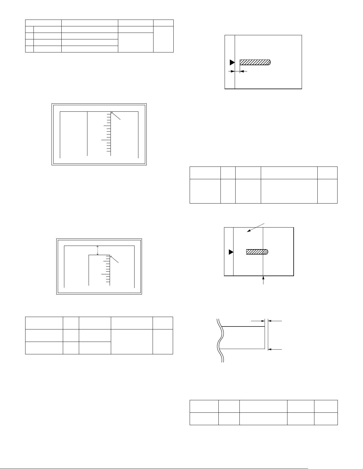
(1) Print start position adjustment
1) Execute SIM 50-5.
Default
450
450
450
2) Touch the item to be adjusted.
400
450
450
400
AR-5726/5731 ADJUSTMENTS 5 - 2
The item and the currently set value are highlighted.
3) Press the [P] key.
The display is shifted to the copy menu.
4) Select the paper feed tray, the print density, and the duplex mode.
Enter the adjustment value with the 10-key.
5) Press the [START] key.
Copying is started.
Character
(145mm/s)
Character/Photo
(145mm/s)
Toner save
(145mm/s)
Character
(122mm/s)
Character/Photo
(122mm/s)
Toner save
(122mm/s)
Setting
range
350-
750
Default
590
590
590
540
590
590
540
Page 22
Item Content Setting range Default
5
10
0mm
0mm
5
10
2.5mm
2.5mm
A4 (8.5" x 11")
Paper rear edge
Void amount (Standard value: 4mm or less)
Scale image
Paper rear edge
1TRAY1
2OPTION
3MANUAL
4DUPLEX
1st tray 0-99
Option tray
Manual feed
1-99
Back print
53
6) Measure the distance H between the paper lead edge and the
image print start position. Set the image print start position set
value again.
• 1 step of the set value corresponds to about 0.127mm shift.
• Calculate the set value from the formula below.
99 – H/0.127 (mm) = Image print start position set value
<H: Print start position measurement value (mm)>
∗ Fit the print edge with the paper edge, and perform the lead
edge adjustment.
Example:99 – 5/0.127 = 99 – 39.4 = about 59
Note : FIf the set value is not obtained from the above formula, per-
form the fine adjustment.
7) Execute SIM 50-1-2 to adjust the main tray lead edge void.
• 1 step of the set value corresponds to about 0.127mm shift.
• Calculate the set value from the formula below.
B/0.127 (mm) = Lead edge void adjustment value
<B: Lead edge void (mm)>
(2) RSPF image lead edge position adjustment
1) Set a scale on the OC table as shown below.
Note: Since the printed copy is used as a test chart, put the scale in
paralleled with the edge lines.
2) Make a copy, then use the copy output as an original to make an
RSPF copy again.
3) Check the copy output. If necessary, perform the following adjustment procedures.
4) Execute SIM 50-6.
5) Set the RSPF lead edge position set value so that the same image
is obtained as that obtained in the previous OC image lead edge
position adjustment.
<Adjustment specification>
Adjustment
mode
RSPF
image lead
edge
SIM Set value Spec value
50-6 1 step:
0.127mm
shift
Lead edge void:
1 – 4mm
Image loss: 3mm or less
Setting
range
1 – 99
position
(3) Rear edge void adjustment
1) Set a scale as shown in the figure below.
Example: When setting the lead edge void to 2.5mm:
2.5 /0.127 = about 20
<Adjustment specification>
Adjustment
mode
Main tray lead
SIM Set value Spec value
50-1-2B/0.127 Lead edge void:
edge void
Print start
50-5 99 – H/0.127
position
[H: Print start position measurement value (mm),
B: Lead edge void (mm)]
1 – 4mm
Image loss: 3mm
or less
AR-5726/5731 ADJUSTMENTS 5 - 3
Setting
range
1 – 99
2) Set the document size to A4 (8.5" x 11"), and make a copy at
100%.
3) If an adjustment is required, follow the procedures below.
4) Execute SIM 50-1 and set the density mode to DEN-B. The currently set adjustment value is displayed.
5) Enter the set value and press the start key.
The correction value is stored and a copy is made.
<Adjustment specification>
Adjustment
mode
Rear edge
void
SIM Set value
50-1-6
1 step: 0.127mm
shift
Spec
value
4mm or
less
Setting
range
1 – 99
Page 23
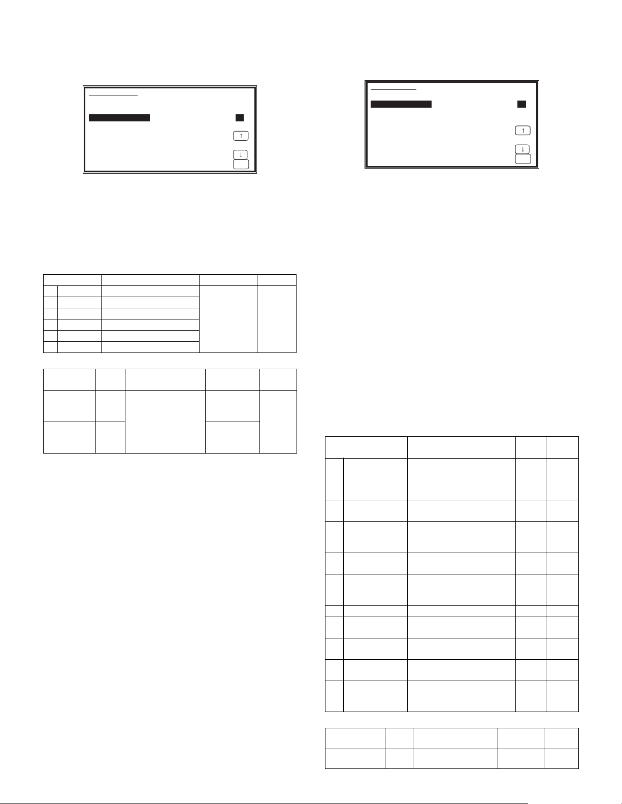
(4) Paper off center adjustment
SIMULATION 50-10
50
1/1
OK
PRINT OFF-CENTER ADJUSTMENT. INPUT VALUE 1-99, AND
PRESS START.
1: BYPASS 50
2: TRAY1 50
3: TRAY2 50
4: TRAY3 50
5: TRAY4 50
6: DUPLEX 50
SIMULATION 50-1
43
1/1
OK
LEAD EDGE ADJUSTMENT. INPUT VALUE 1-99, AND PRESS START.
1: RRC-A 43 2: DEN-A 18
3: DEN-A -MANUAL 18 4: DEN-A -OPTION 18
5: DEN-A -DUPLEX 18 6: DEN-B 3
7: DEN-B-DUP 50 8: SIDE VOID 18
9: SIDE VOID-DUP 18 10: LOSS(OC) 3
1) Set a test chart (UKOG-0089CSZZ) on the document table.
2) Select a paper feed port and make a copy.
3) Execute SIM 50-10.
4) Touch the item to be adjusted.
The item and the currently set value are highlighted.
5) Press the [START] key.
The display is shifted to the copy menu.
6) Select the paper feed tray and the print density.
Enter the adjustment value with the 10-key.
7) Press the [START] key.
Copying is started.
Item Content Setting range Default
BYPASS
1
TRAY1
2
3
TRAY2
4
TRAY3
TRAY4
5
6
DUPLEX
<Adjustment specification>
Adjustment
mode
Paper off
center
Second
print surface
off-center
Manual paper feed
1st tray
2nd tray
3rd tray
4th tray
Back print
SIM Set value Spec value
50-10-2Add 1: 0.127mm
shift to R side.
Reduce 1:
50-10
0.127mm shift to L
-6
side.
1-99 50
Single:
Center
±2.0mm
Duplex:
Center
±2.5mm
AR-5726/5731 ADJUSTMENTS 5 - 4
Setting
range
1 – 99
(5) Left edge void area adjustment
Note: Before performing this adjustment, be sure to check that the
paper off center adjustment (SIM 50-10) is completed.
1) Execute SIM 50-1.
2) Note down the adjustment value of SIM 50-5 (Items 1, 2, 3, 4), and
change the value to 99.
3) Set SIM 50-1 (Items 2, 3, 4, 5) to 1. (By setting to 1, there is no
void.)
4) Place a chart with a clear lead edge (or a ruler) on the OC document table.
5) Use SIM 50-1 (Item 1) to execute test print. Check the print out and
adjust so that the lead edge image is printed. (1 – 99: About
0.127mm/Step)
6) Reset the adjustment values of SIM 50-5 (Items 1, 2, 3, 4) to the
original values, and execute test print. Check the print out and
adjust so that the lead edge image is printed on the lead edge of
paper. (1 – 99: About 0.127mm/Step).
7) Adjust SIM 50-1 (Items 2, 3, 4, 5) so that the lead edge void on the
print out is the specified value. (1 – 99: About 0.127mm/Step)
8) Similar to procedure 7, adjust SIM 50-1 (Item 6, 7) so that the rear
edge void is the specified value. (1 – 99: About 0.127mm/Step)
9) Similar to procedure 7, adjust SIM 50-1 (Item 8, 9) so that the left
edge void is the specified value. (1 – 99: About 0.127mm/Step)
10) Make an enlargement copy (400%), and check that there is no
shade of the cabinet printed at the lead edge.
11) If there is a shade printed at the lead edge in procedure 9, adjust
SIM 50-1 (Item 10). (1 – 5: About 0.677mm)
* If there is no problem, set to 3.
Item Content
1
RRC-A
Original scan start position
adjustment
Lead edge position
adjustment value (OC)
2
DEN-A
Lead edge cancel
adjustment (Main tray)
3
DEN-A-MANUAL
Lead edge cancel
adjustment
(Manual feed tray)
DEN-A-OPTION
4
Lead edge cancel
adjustment (Option tray)
5
DEN-A-DUPLEX
Lead edge cancel
adjustment
(back of the machine)
DEN-B
6
7
DEN-B-DUP
Rear edge void adjustment 1-99 30
Rear edge void adjustment
(Duplex)
8
SIDE VOID
Left edge void adjustment
(First print surface)
9
SIDE VOID-DUP
Left edge void adjustment
(Duplex)
10
LOSS(OC)
Image loss amount
adjustment (Lead edge
image loss set value) (OC)
<Adjustment specification>
Adjustment
mode
SIM Set value
Left edge void 50-1-81 step: 0.127mm
shift
Setting
range
Default
1-99 43
1-99 18
1-99 18
1-99 18
1-99 18
1-99 50
1-99 18
1-99 18
1-5 3
Spec
value
Setting
range
0.5 – 4mm 1 – 99
Page 24
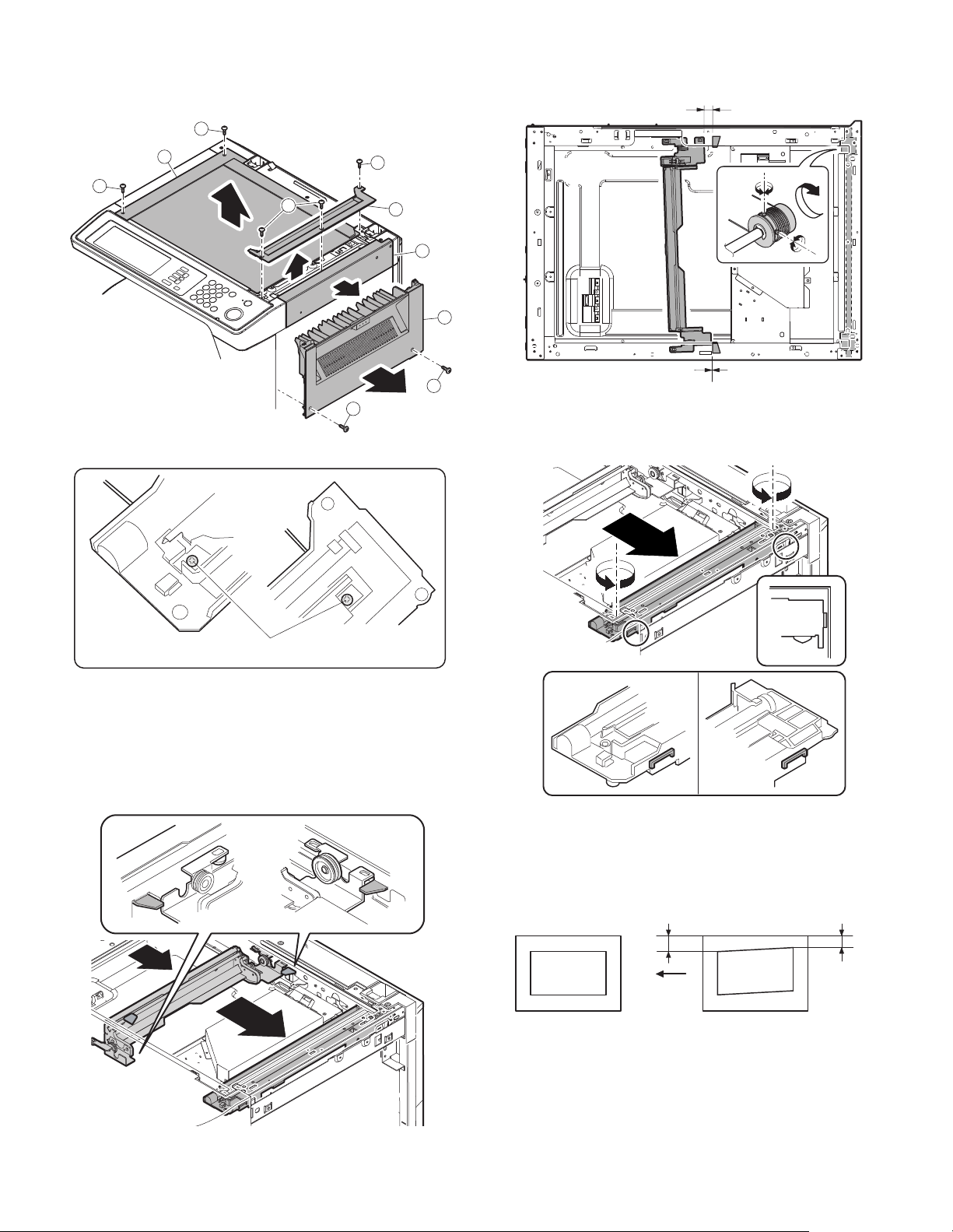
(6) Main scanning direction (FR direction) distortion
Wire fixing screw
Lb
La
Original Copy
Paper exit
direction
balance adjustment
1) Remove the OC glass, the right cabinet and the upper right side
cover.
1
5) Without moving the scanner drive pulley shaft, manually turn the
scanner drive pulley until the positioning plate is brought into contact with No. 2/3 mirror base unit, then fix the scanner drive pulley.
3
1
1
2) Loosen the copy lamp unit wire fixing screw.
1
2
6
5
4
4
6) Put No. 2/3 mirror base unit on the positioning plate again, push
the projections on the front frame side and the rear frame side of
the copy lamp unit to the corner frame, and tighten the wire fixing
screw.
3) Manually turn the mirror base drive pulley and bring No. 2/3 mirror
base unit into contact with the positioning plate.
At that time, if the front frame side and the rear frame side of No. 2/
3 mirror base unit are brought into contact with the positioning
plate at the same time, the mirror base unit parallelism is proper.
If one of them is in contact with the positioning plate, perform the
adjustment of 4).
(7) Sub scanning direction (scanning direction) distortion
adjustment (Winding pulley position adjustment)
This adjustment must be performed in the following cases:
• When the mirror base drive wire is replaced.
• When the lamp unit, or No. 2/3 mirror holder is replaced.
• When a copy as shown is made.
4) Loosen the set screw of the scanner drive pulley which is not in
contact with No. 2/3 mirror base unit positioning plate.
AR-5726/5731 ADJUSTMENTS 5 - 5
Page 25
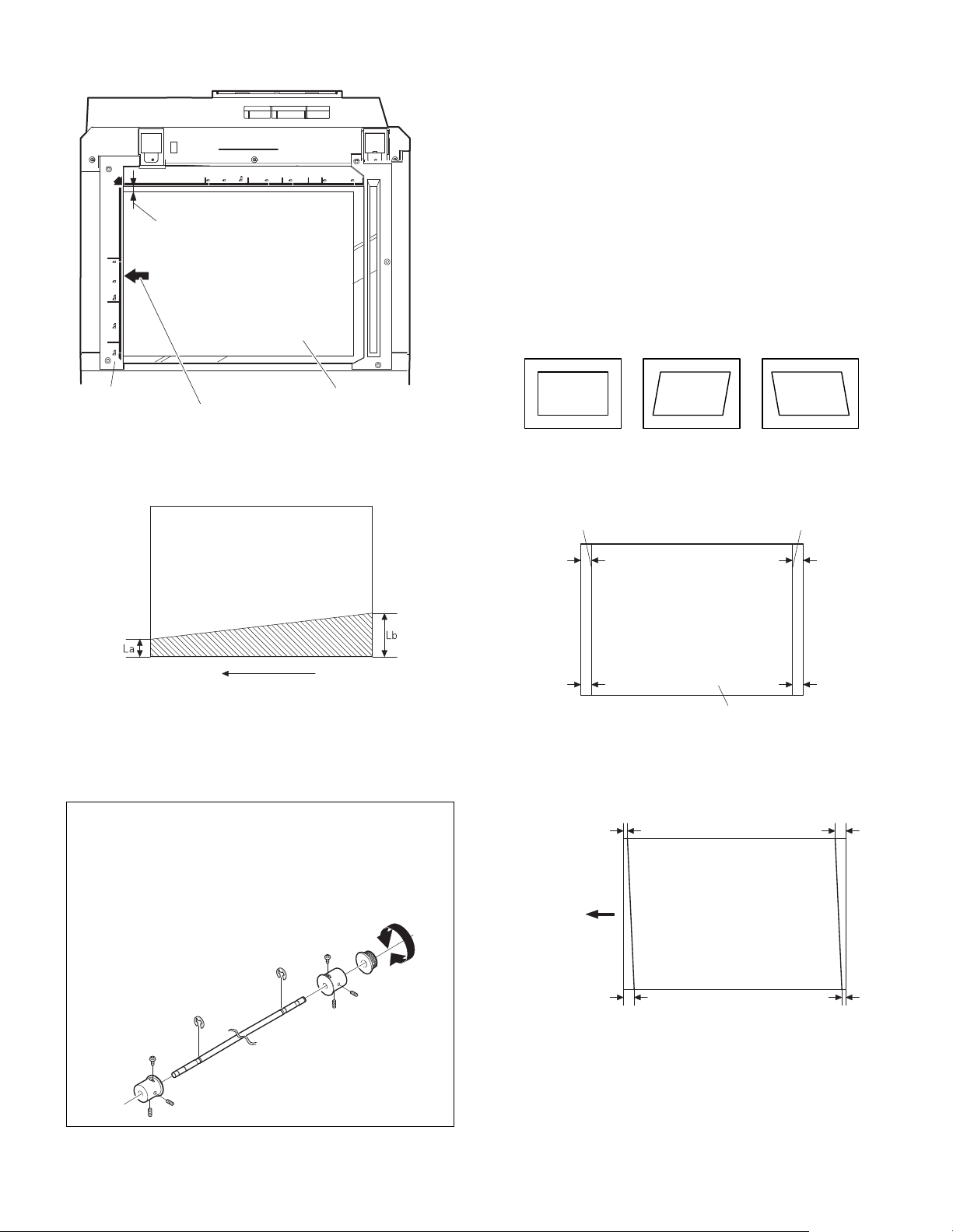
1) Set A3 (11" x 17") white paper on the original table as shown
Paper exit direction
La: Lead edge black background width
Lb: Rear edge black background width
A
B
Rear side
Front side
Original Copy A Copy B
10mm
10mm
10mm
10mm
Parallel line Parallel line
White paper
La
Lb Ld
Lc
Paper exit
direction
below.
Place a little clearance from
the rear side original guide.
Glass holding plate A3 (11" x 17") white paper
Fit the paper edge and
the glass holding plate edge.
2) Open the original cover and make a normal (100%) copy.
3) Measure the width of the black background at the lead edge and at
the rear edge.
<Adjustment specification>
La = Lb
6) Execute the main scanning direction (FR) distortion balance
adjustment previously described in 2) again.
(8) Main scanning direction (FR direction) distortion
balance adjustment (Rail height adjustment)
When there is no skew copy in the mirror base scanning direction and
there is no horizontal error (right angle to the scanning direction), the
adjustment can be made by adjusting the No. 2/3 mirror base unit rail
height.
Before performing this adjustment, be sure to perform the horizontal
image distortion adjustment in the laser scanner section.
This adjustment must be performed in the following cases:
• When the mirror base wire is replaced.
• When the copy lamp unit and no. 2/3 mirror unit are replaced.
• When the mirror unit rail is replaced and moved.
• When a following copy is made.
1) Make an original for the adjustment.
Make test sheet by drawing parallel lines at 10mm from the both
ends of A3 (11" x 17") white paper as shown below. (These lines
must be correctly parallel to each other.)
If the width (La) of the black background at the lead edge is equal
that (Lb) at the rear edge, there is no need to execute the following
procedures of 4) – 7).
4) Loosen the mirror base drive pulley fixing screw on the front frame
side or on the rear frame side.
• When La < Lb
Turn the mirror base drive pulley on the front frame side in the
arrow direction A. (Do not move the mirror base drive pulley shaft.)
• When La > Lb
Turn the mirror base drive pulley on the rear frame side in the
arrow direction A. (Do not move the mirror base drive pulley shaft.)
5) Tighten the fixing screw of the mirror base drive pulley.
2) Make a normal (100%) copy of the test sheet on A3 (11" x 17")
paper. (Fit the paper edge and the glass holding plate edge.)
3) Measure the distances (La, Lb, Lc, Ld) at the four corners as
shown below.
When La = Lb and Lc = Ld, no need to perform the procedures 4)
and 5).
AR-5726/5731 ADJUSTMENTS 5 - 6
Page 26
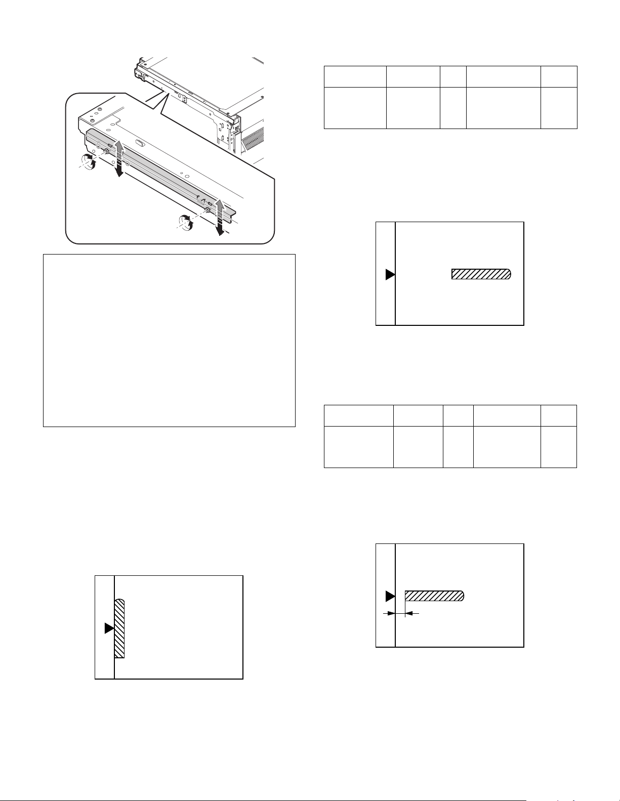
4) Move the mirror base B rail position up and down (in the arrow
direction) to adjust.
• When La > Lb
Shift the mirror base B rail upward by the half of the difference of
La–Lb.
• When La < Lb
Shift the mirror base B rail downward by the half of the difference
of Lb–La.
Example: When La = 12mm and Lb = 9mm, shift the mirror base
B rail upward by 1.5mm.
• When Lc >Ld
Shift the mirror base B rail downward by the half of the difference
of Lc–Ld.
• When Lc < Ld
When Lc < Ld, move the mirror base B on the paper feed side
upward.
∗ When moving the mirror base rail, hold the mirror base rail with
your hand.
<Adjustment specification>
La = Lb, Lc = Ld
5) After completion of adjustment, manually turn the mirror base drive
pulley, scan the mirror base A and mirror base B fully, and check
that the mirror bases are not in contact with each other.
∗ If the mirror base rail is moved extremely, the mirror base may be in
contact with the frame or the original glass. Be careful to avoid this.
(9) Main scanning direction (FR direction) magnification
ratio adjustment (SIM 48-1)
Note: Before performing this adjustment, be sure to check that the
CCD unit is properly installed.
1) Put a scale on the original table as shown below.
<Adjustment specification>
Note: A judgment must be made with 200mm width, and must not be
made with 100mm width.
Adjustment
mode
Main scanning
direction
magnification
ratio
Spec value SIM Set value
At normal:
±1.0%
48-
Add 1: 0.1%
1-1
increase
Reduce 1: 0.1%
decrease
Setting
range
1 – 99
(10) Sub scanning direction (scanning direction)
magnification ratio adjustment
(SIM 48-1-2, SIM 48-1-3)
a. OC mode in copying
Note: Execute the procedure after completion of SIM 48-1-1.
1) Put a scale on the original table as shown below, and make a normal (100%) copy.
2) Compare the scale image and the actual scale.
If necessary, perform the following adjustment procedures.
3) Execute SIM 48-1-2.
4) Enter the set value and press the start key.
The set value is stored and a copy is made.
<Adjustment specification>
Adjustment
mode
Sub scanning
direction
magnification
ratio (OC mode)
b. RSPF mode in copying
Note: Before performing this adjustment, be sure to check that the
CCD unit is properly installed and that OC mode adjustment in
copying has been completed.
1) Put a scale on the original table as shown below, and make a normal (100%) copy to make a test chart.
Spec value SIM Set value
At normal:
±1.0%
48-1-2Add 1:
0.05% increase
Reduce 1:
0.05% decrease
Setting
range
1 – 99
2) Execute SIM 48-1.
3) After warm-up, shading is performed and the current set value of
the main scanning direction magnification ratio is displayed on the
display section in 2 digits.
4) Manual correction mode (SIM48-1-1)
Enter the set value and press the start key.
The correction value is stored and a copy is made.
AR-5726/5731 ADJUSTMENTS 5 - 7
Note: Since the printed copy is used as a test chart, put the scale in
parallel with the front side edge of the glass.
2) Set the test chart on the RSPF and make a normal (100%) copy.
3) Compare the scale image and the actual image.
If necessary, perform the following adjustment procedures.
4) Execute SIM 48-1-3.
5) After warm-up, shading is performed.
The current front surface sub scanning direction magnification ratio
correction value is displayed in two digits on the display section.
Page 27
6) Enter the set value and press the start key.
A
B
R
F
The set value is stored and a copy is made.
7) Execute SIM 48-1-4.
The current back surface sub scanning direction magnification ratio
is displayed in two digits on the display section.
8) Enter the set value and press the start key.
The set value is stored and a copy is made.
<Adjustment specification>
Adjustment mode
Sub scanning
direction
magnification ratio
(RSPF mode)
Spec
value
At normal:
±1.0%
SIM Set value
48-1-3
48-1-4
Add 1:
0.05% increase
Reduce 1:
0.05% decrease
Setting
range
1 – 99
(11) Off center adjustment (RSPF mode)
Note: Before performing this adjustment, be sure to check that the
paper off center is properly adjusted.
1) Place the center position adjustment test chart (sheet with a
straight line in the scan direction at the center) on the RSPF.
2) Make a normal copy from the manual paper feed tray, and check
the printed copy with the test chart.
If any adjustment is required, perform the following procedure.
3) Execute SIM 50-12.
4) After warm-up, shading is performed and the current set value of
the off center adjustment is displayed on the display section in 2
digits.
5) Enter the set value and press the start key.
The set value is stored and a copy is made.
<Adjustment specification>
Adjustment
mode
Original off
center mode
(RSPF
mode)
Spec value SIM Set value
Single: Center
± 3.0mm
Duplex: Center
±3.5mm
50-12 Add 1: 0.1mm
shift to R side
Reduce 1: 0.1mm
shift to L side
Setting
range
1 – 99
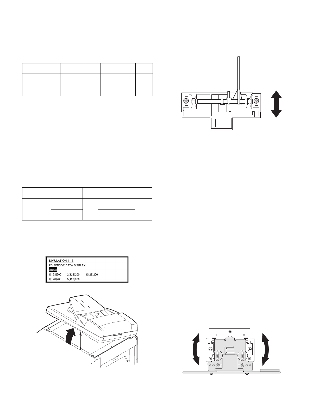
(12) OC (RSPF) open/close detection position adjustment
1) Execute SIM 41-3.
2) Gradually close the OC (RSPF) from the full open position, and
measure distance A when the display on the operation panel
changes. (See the figure below.)
Distance A = Table glass top - OC (RSPF) handle rib
<Adjustment specification>
OC (SPF) open/close position A: 125 – 225mm
3) If the distance is outside the specified range, adjust the open/close
sensor attachment plate position as shown below.
・ Distance < 125mm :
・ Distance > 225mm :
Shift toward A.
Shift toward B.
(13) Original sensor adjustment (SIM 41-2, 41-4)
1) Set A3 (11" x 17") paper on the OC table.
(Keep the SPF (OC cover) open.)
2) Execute SIM 41-2.
3) Keep A=125mm, and execute SIM 41-4. (Do not put paper on the
table.)
4) Check the reaction with SIM 41-1.
(14) RSPF white correction pixel position adjustment
(required in an RSPF model when replacing the lens
unit) (SIM63-7)
1) Fully open the RSPF.
2) Execute SIM 63-7.
3) When the operation panel displays "COMPLETE," the adjustment
is completed.
4) If the operation panel displays "ERROR," perform the following
measures.
• When the display is 0:
Check that the SPF is open.
Check that the lamp is ON. (If the lamp is OFF, check the MCU connector.)
Check that the CCD harness is properly inserted into the MCU connector.
• When the display is 281 or above:
1) Remove the table glass.
2) Remove the dark box.
3) Slide the lens unit toward the front side and attach it, then execute SIM.
• When the display is 143 or below:
1) Remove the table glass.
2) Remove the dark box.
3) Slide the lens unit toward the rear side and attach it, then execute
SIM.
A
∗ When the lens unit is moved, execute the OC main scanning magni-
fication ratio auto adjustment, SIM 48-1-1.
∗ This adjustment is basically O.K. with SIM 63-7.
AR-5726/5731 ADJUSTMENTS 5 - 8
Page 28
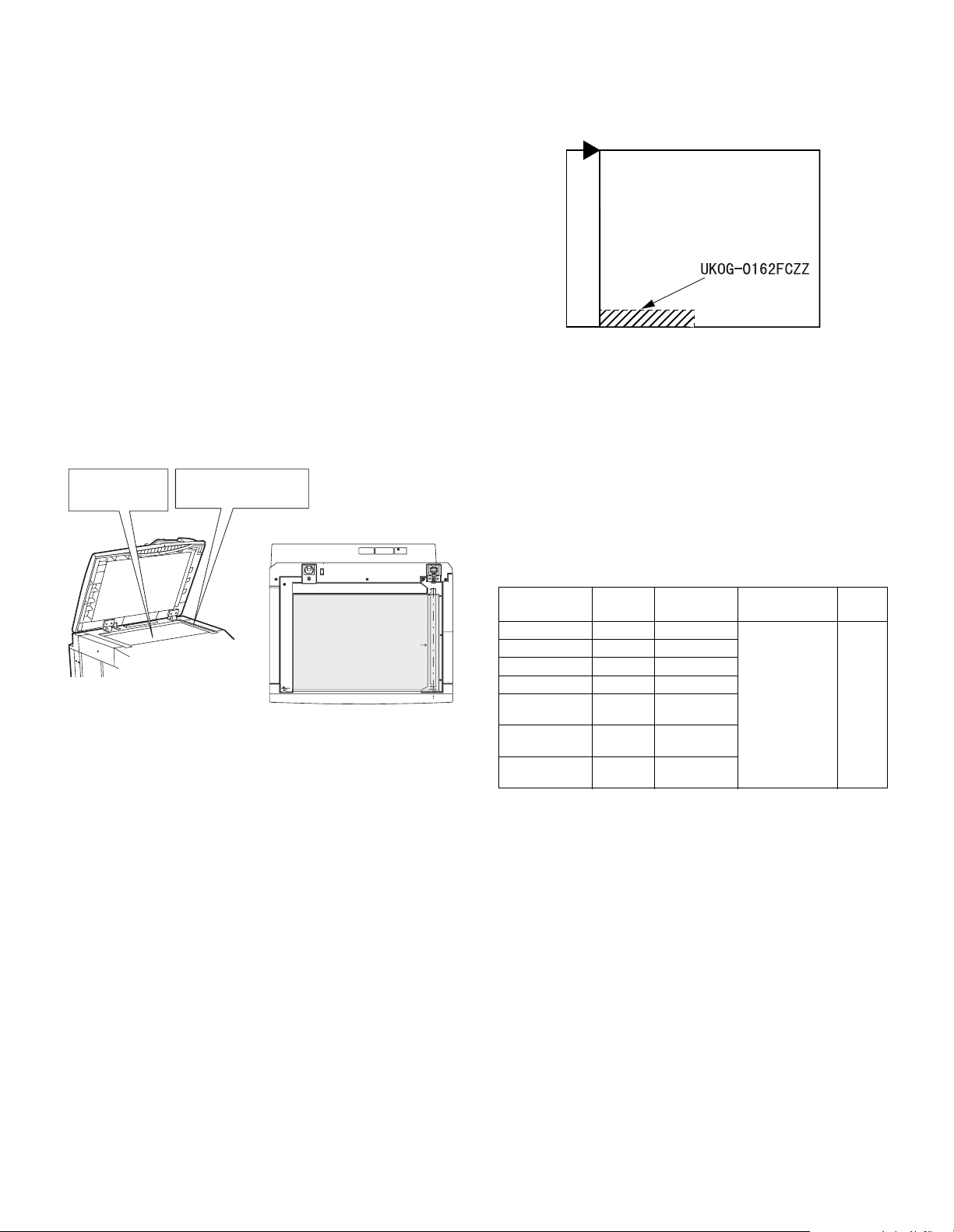
(15) RSPF scan position auto adjustment
Place only the white
paper on the OC glass.
For the RSPF standard-provision
machine, check that the white
Placing the white paper
The white chart must cover
this area.
paper covers the SPF glass.
Rear
Front
[Function]
Used to adjust the RSPF scan position automatically.
[Operation]
1) With the RSPF or the OC cover open, place a white paper background on the OC glass. (In the RSPF standard model, the RSPF
glass surface is included.)
2) Enter SIM53-08, and press [START] button.
Outline of SIM: The optical unit is shifted to recognize the boundary between the OC glass and the RSPF glass cover.
With the same position as the reference, the RSPF scan position is
automatically adjusted.
<Note>
• After completion of the RSPF scan position auto adjustment, the
RSPF lead edge adjustment must be executed. (Both surfaces)
• There must be no other sheet than the black chart on the glass sur-
face.
• Especially when in RSPF scan, the center area is scanned in the
main scan direction. Be careful to prevent external light from entering the scan area.
3) Check that the lead edge is not shifted. (Both surfaces)
(If the original lead edge adjustment has been made properly, even
when the scan position is shifted, it is followed automatically.)
C. Image density (exposure) adjustment
(1) Copy mode (SIM46-2)
1) Set a test chart (UKOG-0162FCZZ) on the OC table as shown
below.
2) Place three or more sheets of A3 (11" x 17") paper on the test
chart.
3) Execute SIM 46-2.
4) After warm-up, shading is performed and the current set value of
the density (exposure) level is displayed on the display section in 2
digits.
For mode selection, use the [10-key].
5) Change the set value with the [10-key] to adjust the copy image
density.
6) Make a copy and check that the specification below is satisfied.
Note: Place originals in the rear reference, and the test chart in the
front reference when adjusting the exposure.
<Adjustment specification>
Density mode
AUTO – "3" is copied. If too bright,
TEXT 3.0 "3" is copied.
TEXT/PHOTO
PHOTO 3.0 "2" is copied.
AE
(TONER SAVE)
TEXT
(TONER SAVE)
TEXT PHOTO
(TONER SAVE)
Exposure
level
3.0 "3" is copied.
3.0 "3" is copied.
3.0 "3" is copied.
Sharp Gray
Chart output
– "3" is copied.
Set value
increase the
quantity displayed
on the copy
quantity display.
If too dark,
decrease the
quantity displayed
on the copy
quantity display.
Setting
range
1 – 99
AR-5726/5731 ADJUSTMENTS 5 - 9
Page 29

[6] SIMULATION
1. General
A. Outline and purpose
The simulation has the following functions to grasp the machine operating status, identify the trouble position and causes in an earlier stage,
and make various setups and adjustments speedily for improving the
serviceability of the machine.
1) Various adjustments
2) Setup of specifications and functions
3) Canceling troubles
4) Operation check
5) Various counters check, setup, and clear
6) Machine operating status (operation history) data check, clear
7) Transfer of various data (adjustments, setup, operations, counters)
The operating procedures and the displays differ depending on the
form of the operation panel of the machine.
B. Code-type simulation
(1) Operating procedures and operations
* Entering the simulation mode
1) #/P key (program) ON
Asterisk (*) key ON → Ready for input of a main code of simulation
2) Entering a main code with the 10-key
3) Entering a sub code with the 10-key
4) Select an item with the scroll key and the item key.
5) The machine enters the mode corresponding to the selected item.
Press START key to start the simulation operation.
To cancel the current simulation mode or to change the main code
and the sub code, press the SYSTEM SETTINGS key.
* Canceling the simulation mode to return to the normal mode
1) Press CLEAR ALL key.
(2) How to change the simulation adjustment value set by
the touch panel in the adjustment value entry process
a. Target SIM list
3-7, 8-1, 8-2, 8-3, 8-10, 8-11, 8-12, 9-5, 43-1, 44-34, 46-2, 46-9, 46-10,
46-11, 46-18, 46-20, 46-30, 46-31, 48-1, 48-2, 50-1, 50-5, 50-6, 50-10,
50-12, 51-1, 51-2, 51-9, 53-7
b. Touch panel operating procedure
• In the adjustment value setup menu, the selected item is highlighted.
Change is made to the highlighted simulation adjustment value.
• If all the list of the adjustment items is not shown on one page, touch
[↑] and [↓] button to shift the page.
• To change an adjustment value, touch the select the item to change
the adjustment value. (The selected item is highlighted.) Enter the
adjustment value and perform one of the following procedures, and
the display of the adjustment value of the selected item is renewed
as well as the adjustment value.
1) Touch [OK] button.
2) Touch another selected item to change the selection state.
3) If all the list of the adjustment items cover two or more pages,
touch [↑] and [↓] button to shift the page.
4) Press [START] key.
* For simulations which allow confirmation print, copying is started
after changing the adjustment value.
(46-2, 46-9, 46-10, 46-11, 46-18, 48-1, 48-2, 50-1, 50-5, 50-6, 50-10,
50-12, 51-2, the bold-faced items in the above list.)
* If the entry value is outside the adjustable range, an error buzzer
sounds and the adjustment value is not renewed. Page shift is not
made, either.
→ Asterisk (*) key ON → CLEAR key ON →
→ START key ON
→ START key ON
AR-5726/5731 SIMULATION 6 - 1
Page 30
YES
YES
YES
NO
NO
YES
NO
NO
NO
YES
YES
YES
NO
NO
NO
NO
YES
YES
START (Normal mode)
Press the #/P key.
Press the asterisk (*) key.
Press the clear key.
Press the asterisk (*) key.
Standby for entry of
SIM code.
Standby for entry of
SIM sub code.
Enter the main code of
SIM with the 10-key.
Enter the sub code of
SIM with the 10-key.
The main code of SIM
is displayed.
Press the START key.
Press the START key.
Is there a sub code ?
Is there a item
selection?
Select the mode and the
item with the ↑ ↓ key
and the item key.
Operation check ?
Operating conditions
check ?
Data clear ?
Adjustments
or setting (counter data
change) ?
4
1
L1
3
2
L1
1
4
2
3
Press the START key.
Operation is made according
to the selected mode and item.
Operation is made according
to the selected mode and item.
Press the START key.
Press the START key.
Select "YES".
The selected mode and
the item are cleared.
The display is made according
to the selected mode and the item.
Do you
want to change the
content ?
Enter the new setting and
adjustment values.
Operation is made according
to the select ed mode and the it
(Other modes)
Press the START key.
The changed content
is stored.
NO
YES
Press the SYSTEM
SETTINGS key
Is it the same
simulation ?
Do you
want to end the
simulation ?
Press the SYSTEM
SETTINGS key
Do you want
to perform another
simulation ?
Press the clear all key.
The simulat
Returns to START
(Normal mode).
ion mode
is canceled.
If "Operation condition check"
refer to "Sensor display", this
process is not necessary.
∗
In the cause of SIM which is set by touch panel, the
changed content can be stored by the following key, touch.
·
[OK] key
·
Other item selection
·
↑ ↓ key
AR-5726/5731 SIMULATION 6 - 2
Page 31
2. Simulation code list
Code
Main Sub
Used to check the operation of the scanner unit
1
1
2
3
4
5
6
7
8
9
10 0
and its control circuit.
Used to check the operation of sensor and detector
2
in the scanning (read) section and the related circuit.
Used to check the operation of the RSPF unit and
1
the related circuit.
Used to check the operation of sensors and detectors
2
in the RSPF unit and the related circuit.
Used to check the operation of the loads in the
3
RSPF unit and the control circuits.
Used to check the operation of sensor and detector
2
in the finisher and the related circuit.
Used to check the operation of the load in the
3
finisher and the control circuit.
10
Used to make each adjustment of the finisher.
Used to check the shifter operation.
Reciprocating operations are continuously
11
performed or the home position is checked.
(The shifter is shifted to the home position or
moved in one way by the specified steps.)
Used to check the operation of sensor and detector
2
in the option tray and the related circuit.
Used to check the operation of the load in the
3
option tray and the control circuit.
Used to check the operation of the display (LED),
1
LCD in the operation panel, and control circuit.
Used to check the operation of the heater lamp and
2
the control circuit.
Used to check the operation of the copy lamp and
3
the control circuit.
Used to check the operation of the loads (clutches
1
and solenoids) in the paper transport system and
the control circuit.
Used to check the operation of each fan motor and
2
its control circuit.
1 Used to set the aging operation conditions.
6 Used to set the cycle of intermittent aging.
8 Used to set the display of the warm-up time.
Used to check and adjust the operation of the
1
developing bias voltage in each copy mode and the
control circuit.
Used to check and adjust the operation of the main
2
charger grid voltage in each copy mode and the
control circuit.
Used to check and adjust the operation of the
10
developing bias voltage in each printer mode and
the control circuit.
Used to check and adjust the operation of the main
11
charger grid voltage in each printer mode and the
control circuit.
Used to check and adjust the operation of the
13
developing bias voltage in FAX mode and the
control circuit.
Used to check and adjust the operation of the main
14
charger grid voltage in FAX mode and the control
circuit.
Used to check and adjust the operation of the load
1
(motor) in the duplex section and the control circuit.
4 Duplex motor RPM setting
Used to adjust the timing of switching from normal
5
rotation to reverse rotation or from reverse rotation
to normal rotation of the duplex motor.
Used to check the operation of the toner motor and
its control circuit.
Function
Code
Main Sub
14 0
16 0 Used to cancel the self-diag U2 trouble.
17 0 Used to cancel the self diag “PF” trouble.
21 1 Used to set the maintenance cycle.
22
24
25
26 1
Used to cancel excluding the self-diag U2/PF
troubles.
1 Used to check the counter value of each section.
Used to check the total numbers of misfeed and
troubles. (When the number of misfeed is
2
considerably great, it is judged as necessary for
repair. The misfeed rate is obtained by dividing this
count value with the total counter value.)
Used to check the misfeed positions and the
number of misfeed at each position.
3
(When the number of misfeed is considerably
great, it can be judged as necessary for repair.)
4 Used to check the total trouble (self diag) history.
Used to check the ROM version of each unit
5
(section).
Used to print each system setting, the account
6
information, and the machine adjustment values.
7 Used to display of the administrator password.
8 Used to display the original, staple counter.
Used to check the number of use of each paper
9
feed section. (the number of prints)
10 Used to check the system configuration.
Used to display the FAX send/receive counter
11
(FAX reception and print counter).
Used to check the misfeed positions and the
number of misfeed at each position.
12
(When the number of misfeed is considerably
great, it can be judged as necessary for repair.)
13 Used to display the CRUM type.
Used to display the scanner counter in the network
19
scanner mode.
Used to clear the misfeed counter, the misfeed
history, the trouble counter, and the trouble history.
1
(The counters are cleared after completion of
maintenance.)
Used to clear the number of use (the number of
2
prints) of each paper feed section.
Used to clear the number usage data of the stapler,
3
RSPF, and scanning.
4 Used to reset the maintenance counter.
Used to reset the developer counter.
5
(The developer counter of the DV unit which is
installed is reset.)
6 Used to clear the copy counter.
Used to clear the OPC drum (membrane decrease)
7
correction counter. (This simulation is executed
when the OPC drum is replaced.)
Used to clear the printer counter and other
9
counters.
10 FAX counter data clear
Used to clear the scanner counter in the network
15
scanner mode.
Used to check the operation of the main drive
(excluding the scanner section) and to check the
1
operation of the toner concentration sensor.
(The toner concentration sensor output can be
monitored.)
Used to make the initial setting of toner
2
concentration when replacing developer.
Used to set whether the job separator is installed
or not. (Since this cannot be detected by hardware
detection, it is set in this simulation.)
Function
AR-5726/5731 SIMULATION 6 - 3
Page 32
Code
Main Sub
2
3
5
6
12 Used to input the Software Key for E-MAIL RIC.
14
18 Used to set enable/disable of toner save operation.
22
30
35
26
30
40
41
36
37
38
50
56 Gamma life correction setting
57 Used to set the model code.
60
71
72
1
2
1
2
3
1
2
3
4
Function
Used to set whether the automatic detection of
paper size is made or not.
Used to set the specifications of the auditor.
Setting must be made depending on the use
condition of the auditor.
Used to set the count mode of the total counter and
the maintenance counter.
Used to set the specifications depending on the
destination.
Used to input the Software Key for the PS
extension kit.
Used to set the specification (language display) for
the destination.
Used to set ON/OFF of the heater lamp slow-up
control conforming to the CE mark control.
Used to set whether the same continuous troubles
are displayed as one trouble or the series of
troubles with SIM 22-4 when the same troubles
occur continuously.
Used to set whether the machine is stopped or not
when the maintenance counter life is expired.
Used to set whether the machine is stopped or not
when the developer counter life is expired.
Used to set whether the machine is stopped or not
when the drum counter life is expired.
Used to set ON/OFF of the black and white
reversion function.
Used to set enable/disable of the FAX mode key
when FAX is not installed. (When FAX is installed,
the FAX mode is enabled regardless of this setup.)
In the power save time setting, the pre-heat (preheat mode setting) and the auto power shut off
time can be set to the short time setup (pre-heat: 1
min, auto power shut off: 1 min) and the long time
setup (pre-heat: 15min, auto power shut off:
60min).
The letterhead support is set.
When “Letterhead paper setting” is selected, the
set value of SIM 26-46 (Image output direction
setting) is set to “Setting Enable” accordingly.
Used to display the sensor status attached to the
machine.
Used to display the status of the sensors attached
to the standard tray and the manual feed tray. (Use
SIM 4-2 for the option trays.)
The sensor of an uninstalled tray is not displayed.
Used to check the sensor of the machine manual
feed tray.
Used to adjust the manual paper feed tray paper
width detector detection level.
The AD conversion value of manual feed width
detection is displayed.
Used to check the document size detection photo
sensor.
Used to adjust the detection level of the document
size photo sensor.
Used to check the light reception level and the
detection level of the original size detection photo
sensor.
Used to adjust the detection level of OC 20
degrees.
Code
Main Sub
1 Used to set the fusing temperature.
43
44
46
48
50
10
1
2 Drum life correction setting
3 Used to set the DV count correction.
9
14
16
17
34
40
2
9
10
11
12
13
14
15
16
18 Used to adjust inclination for each exposure mode.
19
20
30
31
39 Used to switch the FAX send image quality.
1
2
3
8 FAX magnification adjustment (read)
9 FAX magnification adjustment (print)
1 Used to adjust the copy lead edge position.
5
6
8 FAX lead edge adjustment (read)
9 FAX lead edge adjustment (print)
Function
Used to set the paper feed cycle timing when
printing postcards.
Used to make various setups in each mode of
process control.
Used to display the process control correction
information.
Used to display the environment (temperature,
humidity) correction information.
Used to set the toner density control correction
value.
Used to display the toner density control reference
value.
Used to set the transfer current value in each
mode.
Used to set the time from the start of the main
motor rotation (Ready) to the start of toner supply
in previous rotation after turning on the power.
Used to set the exposure level in each exposure
mode.
Used to adjust the shift amount and the inclination
value for each level (1 to 5) of the exposure mode
(Text).
Used to adjust the shift amount and the inclination
value for each level (1 to 5) of the exposure mode
(Text/Photo).
Used to adjust the shift amount and the inclination
value for each level (1 to 5) of the exposure mode
(Photo).
FAX exposure level adjustment
(1 mode automatic adjustment)
FAX exposure level adjustment
(Normal mode individual adjustment)
FAX exposure level adjustment
(Fine text mode individual adjustment)
FAX exposure level adjustment
(Super Fine mode individual adjustment)
FAX exposure level adjustment
(Ultra Fine mode individual adjustment)
Used to set the control method of the exposure
mode.
Used to set the exposure correction value of SPF/
RSPF for OC exposure.
Used to set the AE and the limit value in AE
(Toner save).
Used to set the AE and the limit value in AE
(Toner save).
Used to adjust the copy mode magnification ratio
(main scanning direction, sub scanning direction).
Used to adjust the scanner mode magnification
ratio (main/sub scanning direction).
Used to adjust the print mode magnification ratio
correction.
Used to adjust the print image position (top margin)
on the print paper in the print mode.
Used to adjust the print image position (top margin)
on print paper in the copy mode. (RSPF)
AR-5726/5731 SIMULATION 6 - 4
Page 33
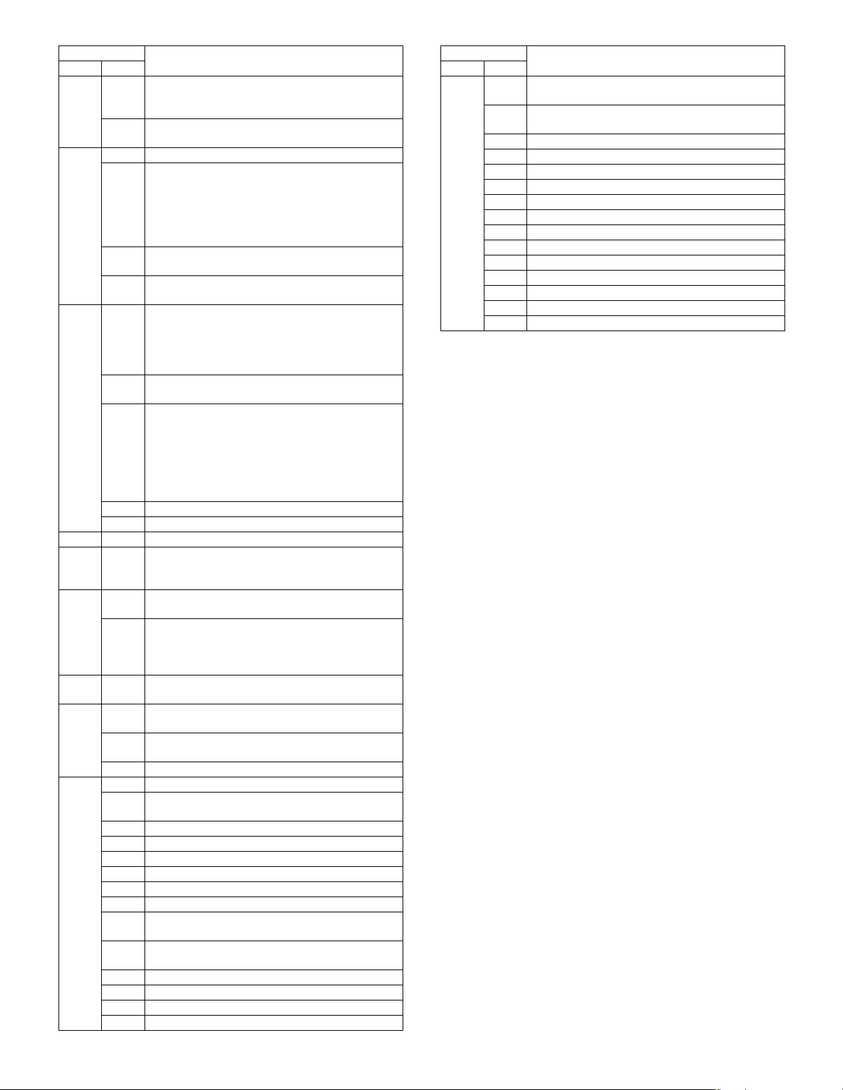
Code
Main Sub
Used to adjust the print image center position.
10
(Adjustment can be made for each paper feed
50
51
53
55 1 Used to set the soft switch.
61 1
63
64 1
65
66
section.)
Used to adjust the print image center position.
12
(Adjustment can be made for each document mode.)
1
Used to adjust the OPC drum separation pawl ON time.
Used to adjust the contact pressure of paper onto
the resist roller in each section (copier paper feed
section, duplex paper feed section, RSPF paper
2
feed section). (When the print image position
varies greatly for the paper or when a lot of paper
jam troubles occur, the adjustment is required.)
Used to set the OPC drum separation pawl
8
operation inhibit. (ON/OFF)
Used to adjust the OPC drum separation voltage
9
ON/OFF timing.
Used to adjust the detection level of the RSPF
width. The adjustment method is the 4-point
6
system. Set the guide to Max. (A3/WLetter)
position, A4R/Letter R position, A5R/Invoice R
position, and Min. position for adjustment.
Used to enter the RSPF width detection
7
adjustment value.
Used to adjust the RSPF scan position of the
mirror unit automatically. For the RSPF scan
position automatic adjustment, the mirror unit is
8
shifted to 11mm before the RSPF glass cover
edge, and is operated automatically to scan
images by the unit of 1 step, detecting the position
up to the glass cover automatically.
9 RSPF read position adjustment
10 RSPF exp adjustment
Used to check the LSU (polygon motor) operation.
Check speed can select 145mm/s or 122mm/s
individually.
Used to check the result of shading correction.
1
(The shading correction data are displayed.)
Used to adjust the RSPF white correction start
pixel position automatically.
7
This adjustment is performed after the lens unit is
replaced.
Used to check the operation of the printer function
(auto print operation).
Used to adjust the touch panel (LCD display
1
section) detection position.
Used to check the touch panel (LCD display
2
section) detection position adjustment result.
Used to check the key inputs of the operation panel.
5
1 Used to change and check the FAX-related soft SW.
Used to clear the FAX-related soft SW.
2
(Except for the FAX adjustment values)
3 FAX PWB memory check
4 Signal send mode (Signal send level: Max.)
Signal send mode (Signal send level soft SW setting)
5
6 Printing the confidential password
7 Print the screen memory contents
10 Image data memory clear
Used to send 300bps signals.
11
(Signal send level: Max.)
Used to send 300bps signals.
12
(Signal send level: Set by soft SW)
13 Used to register the dial numbers.
14 Used to perform the dial test. (10 PPS send test)
15 Used to perform the dial test. (20 PPS send test)
Used to perform the dial test. (DTFM signal send test)
16
Function
Code
Main Sub
17
18
19 Used to write the SRAM data to the Flash ROM.
20 Used to write the Flash ROM data to the SRAM.
21 FAX information print
22 Handset sound volume adjustment (Japan only)
66
24 Used to clear the FAST storage data. (SEC only)
30 Used to set the TEL/LIU.
31 Used to set the TEL/LIU.
32 Receive data check
33 Signal detection check
34 Communication time measurement display
37 Speaker sound volume adjustment
41 CI signal check
52 Pseudo-ringer check
Function
Used to check the DTFM signal send operation.
(Signal send level: Max.)
Used to check the DTFM signal send operation.
(Signal send level: Set by soft SW.)
AR-5726/5731 SIMULATION 6 - 5
Page 34
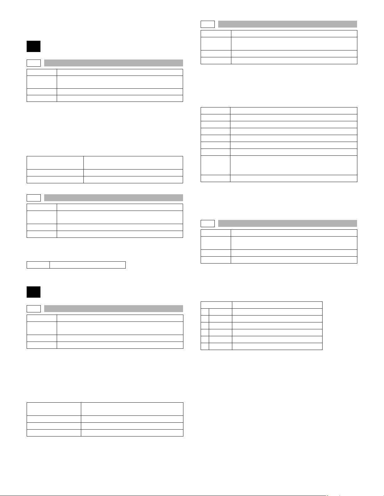
3. Details of simulation
1
1-1
Purpose Operation test/check
Function
(Purpose)
Section Optical (Image scanning)
Item Operation
Operation/procedure
Enter the number of operations, and set the magnification ratio and the
original size.
1. Select the desired item, and press the [START] key.
2. Enter the set value with the 10-key, and press the [START] key.
The scanner unit operates at the speed corresponding to the set value.
The scan counter is displayed during execution.
Set magnification ratio
Document size Varies depending on the destination.
Set number of times 1 to 999 (0: Continuous operation)
1-2
Purpose Operation test/check
Function
(Purpose)
Section Optical (Image scanning)
Item Operation
Operation/procedure
The status of sensors and detectors in the scanner section is displayed. The active sensors and detectors are highlighted.
MHPS Mirror home position sensor
Used to check the operation of the scanner unit and its
control circuit.
25% to 400% (1% increment)
(Default 100%)
Used to check the operation of sensor and detector in
the scanning (read) section and the related circuit.
2
2-1
Purpose Operation test/check
Function
(Purpose)
Section RSPF
Item Operation
Operation/procedure
Enter the number of operations, and set the magnification ratio and the
original size.
1. Select the desired item, and press the [START] key.
2. Enter the set value with the 10-key, and press the [START] key.
The RSPF unit operates at the speed corresponding to the set value.
The scan counter is displayed during execution.
Set magnification ratio
Document size Varies depending on the destination.
Duplex Selectable only when RSPF is installed.
Set number of times 1 to 999 (0: Continuous operation)
Note: Executable only when the RSPF is installed.
Used to check the operation of the RSPF unit and the
related circuit.
50% to 200% (1% increment)
(Default 100%)
2-2
Purpose Operation test/check
Function
(Purpose)
Section RSPF
Item Operation
Operation/procedure
The operations of sensors and detectors in the RSPF section are displayed.
The active sensors and detectors are highlighted.
(For the original size, the detection result of the original size displayed
on the copy menu is highlighted.)
EMPS Original empty sensor
DLS1 Original length sensor (Small)
DLS2 Original length sensor (Large)
FGOD RSPF paper feed cover open/close sensor
DFD RSPF paper entry sensor
RDD RSPF original exit sensor
OPCLS Book sensor
SWD_LEN
SWD_A/D Original detection width sensor A/D value
RSPF width detection size (One of the following is displayed.)
A4/A3, LT/WLT, B5/B4, INV/LTR, A5/A4R, B5R, EXTRA, 8K/16K,
16KR
Note: Executable only when the RSPF is installed.
2-3
Purpose Operation test/check
Function
(Purpose)
Section RSPF
Item Operation
Operation/procedure
Select the load to be checked with the 10-key, and press the [START]
key.
The motor for 10sec, the solenoid ON for 500msec, OFF for 500msec.
(20 times)
Item Content
1 DTM-F RSPF motor forward rotation
2 DTM-R RSPF motor reverse rotation
3 DFCL RSPF paper feed clutch
4 CLH RSPF PS clutch
5 GSOL Document exit gate solenoid
6 RSOL Document exit pressure solenoid
Note: Executable only when the RSPF is installed.
Used to check the operation of sensors and detectors
in the RSPF unit and the related circuit.
Original detection width sensor
(Unit of 0.1mm. “Width x 10” is displayed. Example: For
300mm, 3000 is displayed.)
Used to check the operation of the loads in the RSPF
unit and the control circuits.
AR-5726/5731 SIMULATION 6 - 6
Page 35
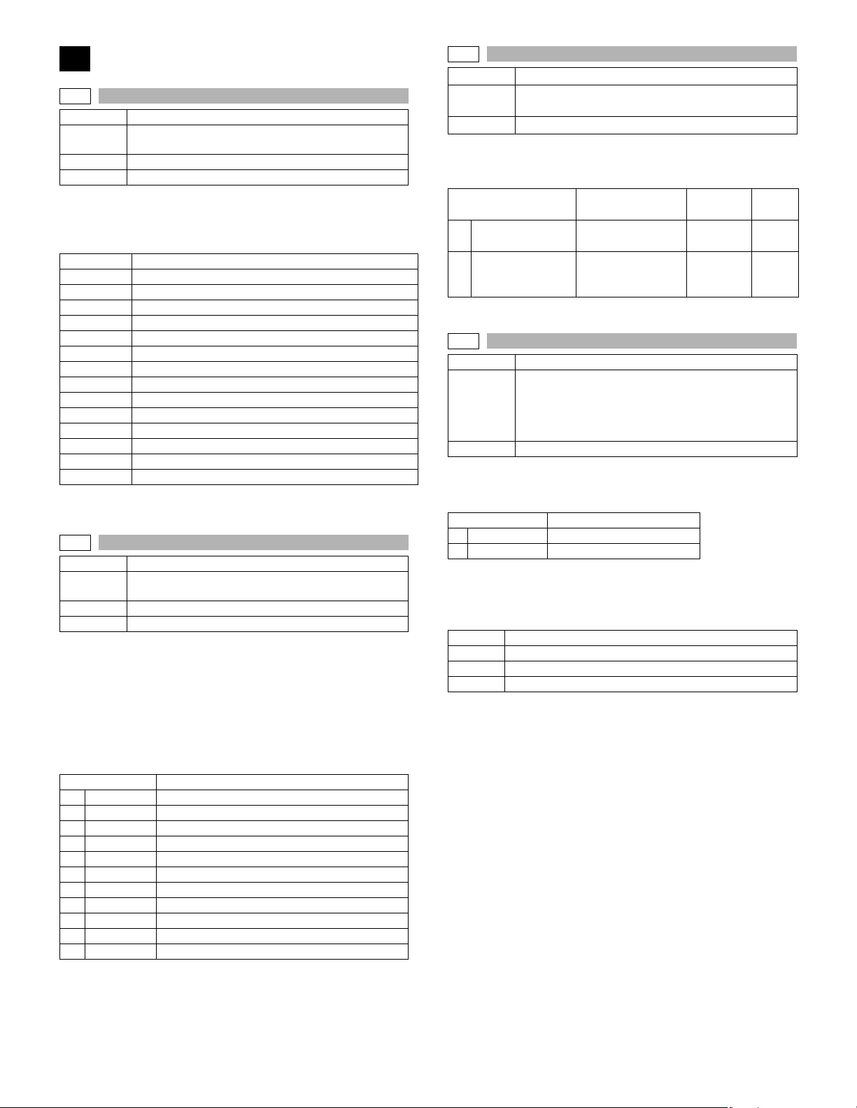
3
3-2
Purpose Operation test/check
Function
(Purpose)
Section Finisher
Item Operation
Operation/procedure
Used to display the operations of sensors and detectors in the finisher
section.
The active sensors and detectors are highlighted.
FDTPD Paper delivery tray paper detector
FSTPD Staple tray paper detector
FAPHPS-R Paper alignment plate HP sensor R
FAPHPS-F Paper alignment plate HP sensor F
FDRPS Delivery roller position sensor
FPPD1 Paper pass detector
FDTLLS Delivery tray lower limit sensor
FTPS Tray position sensor
FPLD Paper level detector
FSSW Safety switch
FSLD Staple lead edge detector
FSED Staple empty detector
FSHPS Staple HP sensor
FPRD Process tray paper rear edge detection
FPLS Paper level sensor
Note: Executable only when the finisher is installed.
3-3
Purpose Operation test/check
Function
(Purpose)
Section Finisher
Item Operation
Operation/procedure
Select the load to be checked with the 10-key, and press the [START]
key.
The finisher main motor operates for 10sec, the staple motor 5 times,
the tray lift-up motor one reciprocating operation, other motors max. 20
reciprocating operations from the home position, the solenoid repeats
500msec ON and 500msec OFF 20 times.
The staple operation motor operates only when there is no cartridge
installed.
1 FTLM Tray lift motor
2 FSM Staple motor
3 FPAM-R Paper alignment motor R
4 FPAM-F Paper alignment motor F
5 FPDM Paper delivery motor
6 FPS Paddle solenoid
7 FPTM Paper transport motor
8 FDRLM Delivery roller lift motor
9 FPGS Paper gate solenoid
10 FARLS Alignment roller lift solenoid
11 FSL Staple light
Used to check the operation of sensor and detector in
the finisher and the related circuit.
Used to check the operation of the load in the finisher
and the control circuit.
Item Content
3-10
Purpose Adjustment
Function
(Purpose)
Item Operation
Operation/procedure
1. Select an item to be adjusted with 10-key, and press [START] key.
2. Enter an adjustment value with 10-key, and press [START] key.
1 FPAM ADJUST
2 FDRLM ADJUST
3-11
Purpose Operation test/check
Function
(Purpose)
Item Operation
Operation/procedure
Select item “1,” and press the [START] key.
The shifter is reciprocated continuously at the specified interval.
1 F-R Reciprocating operation
2 HP CHECK Home position check
[Selection 2]
1. Select item “2,” and press the [START] key.
2. Move the shifter to the home position or in one way by the specified steps with the following keys.
[*] key Shifts the position toward R side by the specified steps.
[0 key Shifts the position toward HP side by the specified steps.
[#] key Shifts to F.
SFTHP Shifter home position (At detection, highlighted)
Used to make each adjustment of the finisher.
Item Content
Paper alignment
width adjustment
Paper delivery roller
descending position
adjustment
Used to check the shifter operation.
Reciprocating operations are continuously performed
or the home position is checked.
(The shifter is shifted to the home position or moved in
one way by the specified steps.)
Item Content
Installation
range
40-60 50
40-60 50
Default
AR-5726/5731 SIMULATION 6 - 7
Page 36
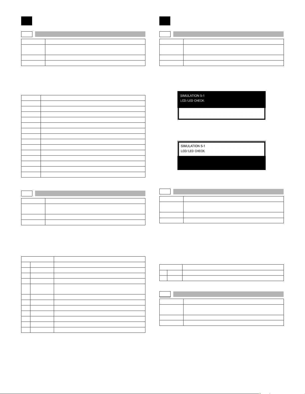
4
5
4-2
Purpose Operation test/check
Function
(Purpose)
Section Paper feed
Item Operation
Operation/procedure
The operating states of the sensor and the detector are displayed.
(Only the installed option trays are displayed. For the standard tray,
use SIM 30-2.)
The active sensors and detectors are highlighted.
PED2 2nd tray paper empty sensor
LUD2 2nd tray paper upper limit detection sensor
PFD2 2nd tray paper pass sensor
CD2 2nd tray empty sensor
PED3 3rd tray paper empty sensor
LUD3 3rd tray paper upper limit detection sensor
PFD3 3rd tray paper pass sensor
CD3 3rd tray empty sensor
PED4 4th tray paper empty sensor
LUD4 4th tray paper upper limit detection sensor
PFD4 4th tray paper pass sensor
CD4 4th tray empty sensor
DSWR2 2nd tray right door detection sensor
DSWR3 3rd tray right door detection sensor
DSWR4 4th tray right door detection sensor
Note: Execution is possible only when the option tray is installed.
Used to check the operation of sensor and detector in
the option tray and the related circuit.
5-1
Purpose Operation test/check
Function
(Purpose)
Section Operation (screen/operation)
Item Operation
Operation/procedure
The LCD is displayed as follows. (All LED’s are ON.)
With the upper half highlighted and the lower half normally displayed,
contrast changes “Standard
(6 sec later)
With the upper half normally displayed and the lower half highlighted,
contrast changes “Standard
* When returning to the sub menu selection menu, the display of the
standard contrast is displayed for an instant.
Used to check the operation of the display (LED), LCD
in the operation panel, and control circuit.
→ MAX → MIN.” in every 2sec.
→ MAX → MIN.” in every 2sec.
4-3
Purpose Operation test/check
Function
(Purpose)
Section Paper feed
Item Operation
Operation/procedure
Select the load to be checked with the 10-key, and press the [START]
key.
The motor for 10sec, the solenoid ON for 500msec, OFF for 500msec.
The lift-up motor operates only when the tray is opened. (20 times)
1 LUM2 2nd tray lift-up motor
2 CPFC2 2nd tray pick-up solenoid
3 CPFS2 2nd tray paper feed clutch
4 TRC2 2nd tray transport roller clutch
5DM
6 LUM3 3rd tray lift-up motor
7 CPFC3 3rd tray pick-up solenoid
8 CPFS3 3rd tray paper feed clutch
9 TRC3 3rd tray transport roller clutch
10 LUM4 4th tray lift-up motor
11 CPFC4 4th tray pick-up solenoid
12 CPFS4 4th tray paper feed clutch
Note: Execution is possible only when the option tray is installed.
Used to check the operation of the load in the option
tray and the control circuit.
Item Content
2nd tray paper transport motor
(3rd tray paper transport motor)
5-2
Purpose Operation test/check
Function
(Purpose)
Section Fusing
Item Operation
Operation/procedure
1. Select the lamp to be checked with the 10-key, and press the
[START] key.
ON/OFF operation of the heater lamp is repeated 5 times in an interval
of 100ms/900ms.
When completing the operation, the cooling fan is rotated at a low speed.
Item Content
Item Content
1 HL1 Heater lamp 1 (Main) operation
2 HL2 Heater lamp 2 (Sub) operation
5-3
Purpose Operation test/check
Function
(Purpose)
Section Optical (Image scanning)
Item Operation
Operation/procedure
When the [START] key is pressed, the copy lamp is lighted for 10sec.
Used to check the operation of the heater lamp and the
control circuit.
Used to check the operation of the copy lamp and the
control circuit.
AR-5726/5731 SIMULATION 6 - 8
Page 37
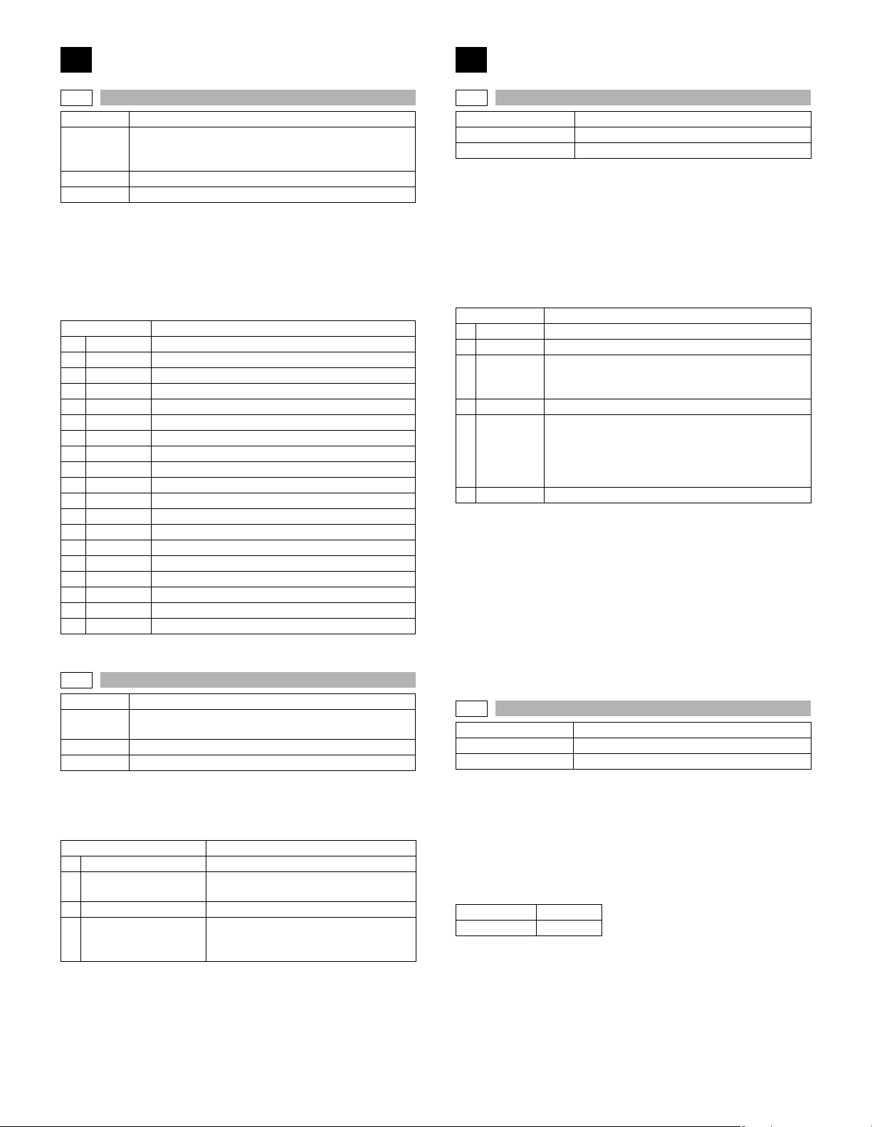
6
7
6-1
Purpose Operation test/check
Function
(Purpose)
Section Paper transport (Discharge/Switchback/Transport)
Item Operation
Operation/procedure
1. Select the load to be checked with the 10-key, and press the
[START] key.
The motor for 10sec, the solenoid ON for 500msec, OFF for 500msec.
(20 times)
When the [SYSTEM SETTINGS] is pressed, the operation is interrupted.
The lift-up motor operates only when the tray is opened.
1 LUM1 1st tray lift-up motor
2 CPFC1 1st tray pick-up solenoid
3 CPFS1 1st tray paper feed clutch
4 MPFS Manual feed pick-up solenoid
5 RRC Resist roller clutch
6 PSPS Separation pawl solenoid
7 OGS Paper exit gate switching solenoid
8 LUM2 2nd tray lift-up motor
9 CPFC2 2nd tray pick-up solenoid
10 CPFS2 2nd tray paper feed clutch
11 TRC2 2nd tray transport roller clutch
12 LUM3 3rd tray lift-up motor
13 CPFC3 3rd tray pick-up solenoid
14 CPFS3 3rd tray paper feed clutch
15 TRC3 3rd tray transport roller clutch
16 LUM4 4th tray lift-up motor
17 CPFC4 4th tray pick-up solenoid
18 CPFS4 4th tray paper feed clutch
19 ROGS Right paper exit gate solenoid
The lift-up motor operates only when the tray is opened.
6-2
Purpose Operation test/check
Function
(Purpose)
Section Others
Item Operation
Operation/procedure
Select the load to be checked with the 10-key, and press the [START]
key.
The selected load is operated for 10sec.
1 VFM Fusing fan operates
2 DCFM&DCFM2
3 VFM2 Fusing exit paper fan operates
VFM&DCFM&DCFM2
3
&VFM2
Used to check the operation of the loads (clutches and
solenoids) in the paper transport system and the
control circuit.
Item Content
Used to check the operation of each fan motor and its
control circuit.
Item Content
Power cooling fan, power cooling fan 2
operations
Fusing fan, power cooling fan, and
power cooling fan 2 are operated at the
same time.
7-1
Purpose Setting/Operation test/check
Function (Purpose) Used to set the aging operation conditions.
Item Operation
Operation/procedure
1. Select the load to be set with the 10-key.
2. Press the [START] key.
When selected without setup, the selected value is registered and
highlighted. When selected with previous setup, the previous setup is
canceled and it is displayed normally.
Press [CA] key, and the simulation will be terminated and the machine
goes into the aging standby mode with the set content.
This setting is canceled by power OFF.
Item Content
1 AGING Aging enable/disable setting
2 MISFEED Jam detection enable/disable setting
3 FUSING*1
4 INTERVL Intermittent setting (Valid only when set to AGING.)
5WARMUP
6 DV CHK. Developing unit detection enable/disable setting
*1: When the machine exits from the fusing ignoring state, the roller
may be cooled down. Therefore, reset the machine to warm up
again.
When, therefore, the simulation is canceled by pressing the [CA]
key or when the copy mode display is shifted to the initial menu
display in the simulation mode of one page copy, the machine is
reset.
Note: In SIM 7-1, pressing [CA] key terminates the simulation and the
machine enters the aging mode without resetting. Therefore, to
perform “4. Intermittent setup,” the intermittent cycle must be set
with SIM 7-6 in advance.
Reset is not performed when the machine enters the aging mode.
7-6
Purpose Setting/Operation test/check
Function (Purpose) Used to set the cycle of intermittent aging.
Item Operation
Operation/procedure
1. Enter the interval aging cycle time (sec) with the 10-key pad.
Refer to SIM 7-1.
2. Press the [START] key.
When the [START] key is pressed in aging, copying is performed continuously. This simulation is used to set the time interval between copy
operations in the unit of second.
This setting is valid when SIM 7-1 (Intermittent setting) is enabled.
Setting range 1-255
Default 3
Fusing operation enable/disable setting
The fusing temperature is not controlled.
The heater is not turned ON.
Warm-up save setting
The machine goes into the ready state only by
shading, disregarding fusing and process control.
After going into the ready state, normal control is
performed.
AR-5726/5731 SIMULATION 6 - 9
Page 38
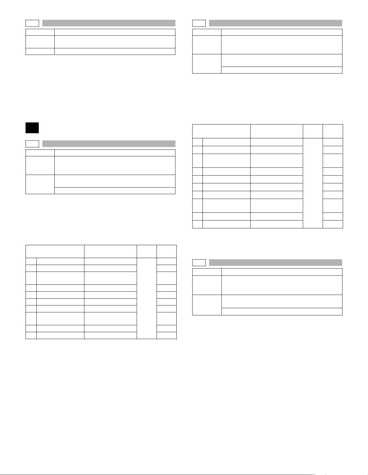
7-8
Purpose Setting/Operation test/check
Function
(Purpose)
Item Operation
Operation/procedure
1. Warm-up starts by the cover open/close.
(Can be performed repeatedly by open/close of the cover.)
2. The warm-up time is counted up and displayed in the unit of sec.
If the [CA] key is pressed at this time, count-up is interrupted to terminate the simulation. (However, warm-up is continued.)
3. After completion of warming up, “WARM UP COMPLETED” is displayed and the control returns to the initial screen.
Used to set the display of the warm-up time.
8
8-1
Purpose Adjustment/Operation test/check
Function
(Purpose)
Section
Operation/procedure
1. Touch the exposure mode to be changed.
The current set value is displayed.
2. Enter the set value with the 10-key.
3. Press the [START] key.
Output is made with the entered value, and the display returns to the
original state.
1 AE (145) AE (145mm/s)
2 TEXT (145) Character (145mm/s) 450
3 T EXT/PHOTO (145)
4 PHOTO (145) Photo (145mm/s) 450
5 TONER SAVE (145) Toner save (145mm/s) 400
6 AE (122) AE (122mm/s) 450
7 TEXT (122) Character (122mm/s) 450
8 T EXT/PHOTO (122)
9 PHOTO (122) Photo (122mm/s) 450
10 TONER SAVE (122) Toner save (122mm/s) 400
∗) Linked with the destinations of SIM 26-6.
(
Linked with the auto exposure mode of SIM 46-19-1.
The minimum increment is 10V.
The result of (Set value) -200/ 10 is stored in the EEPROM.
When reading a value from the EEPROM, the value of (EEP value
*10+200) is used as the set value.
Used to check and adjust the operation of the
developing bias voltage in each copy mode and the
control circuit.
Image process
(Photoconductor/Developing/Transfer/Cleaning)
Developer/Toner hopper
Item Content
Character/Photo
(145mm/s)
Character/Photo
(122mm/s)
Setting
range
200-
650
Default
450
450
450
8-2
Purpose Adjustment/Operation test/check
Function
(Purpose)
Section
Operation/procedure
1. Touch the exposure mode to be changed.
The current set value is displayed.
2. Enter the set value with the 10-key.
3. Press the [START] key.
Output is made with the entered value for 30sec, and the display
returns to the original state.
1 AE (145) AE (145mm/s)
2 TEXT (145) Character (145mm/s) 590
3 TEXT/PHOTO (145)
4 PHOTO (145) Photo (145mm/s) 590
5 TONER SAVE (145) Toner save (145mm/s) 540
6 AE (122) AE (122mm/s) 590
7 TEXT (122) Character (122mm/s) 590
8 TEXT/PHOTO (122)
9 PHOTO (122) Photo (122mm/s) 590
10 TONER SAVE (122) Toner save (122mm/s) 540
Min. unit: 10V increment
∗) Linked with the destinations of SIM 26-6.
(
Linked with the auto exposure mode of SIM 46-19-1.
8-10
Purpose Adjustment/Operation test/check
Function
(Purpose)
Section
Operation/procedure
1. Touch the exposure mode to be changed.
The current set value is displayed.
2. Enter the set value with the 10-key.
3. Press the [START] key.
Used to check and adjust the operation of the main
charger grid voltage in each copy mode and the control
circuit.
Image process
(Photoconductor/Developing/Transfer/Cleaning)
Photo conductor
Item Content
Character/Photo
(145mm/s)
Character/Photo
(122mm/s)
Used to check and adjust the operation of the
developing bias voltage in each printer mode and the
control circuit.
Image process
(Photoconductor/Developing/Transfer/Cleaning)
Developer/Toner hopper
Setting
range
350-
750
Default
590
590
590
AR-5726/5731 SIMULATION 6 - 10
Page 39
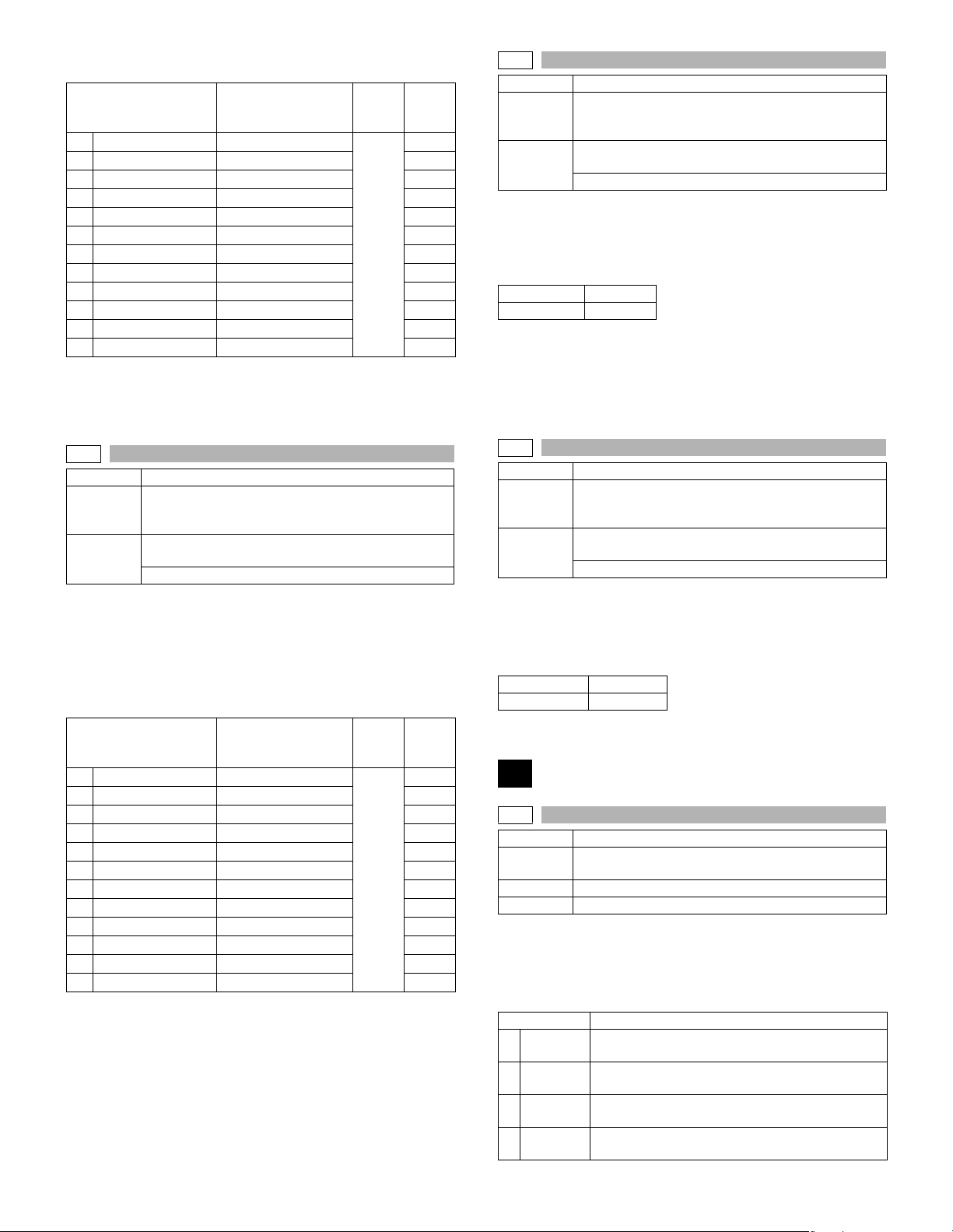
Output is made with the entered value for 30sec, and the display
returns to the original state.
Installa
Item Content
1 DENS1 (145) Density1 (145mm/s)
2 DENS2 (145) Density2 (145mm/s) 370
3 DENS3 (145) Density3 (145mm/s) 420
4 DENS4 (145) Density4 (145mm/s) 530
5 DENS5 (145) Density5 (145mm/s) 600
6 TS (145) Toner save (145mm/s) 250
7 DENS1 (122) Density1 (122mm/s) 300
8 DENS2 (122) Density2 (122mm/s) 370
9 DENS3 (122) Density3 (122mm/s) 420
10 DENS4 (122) Density4 (122mm/s) 530
11 DENS5 (122) Density5 (122mm/s) 600
12 TS (122) Toner save (122mm/s) 250
The minimum increment is 10V.
The result of (Set value) -200/ 10 is stored in the EEPROM.
When reading a value from the EEPROM, the value of (EEP value
*10+200) is used as the set value.
tion
range
200-
650
Default
300
8-13
Purpose Adjustment/Operation test/check
Function
(Purpose)
Section
Operation/procedure
1. Enter the set value with the 10-key.
2. Press the [START] key.
Output is made with the entered value for 30sec. and the display
returns to the original state.
Setting range 200-650
Default 450
The minimum increment is 10V.
The result of (Set value-200) / 10 is stored in the EEPROM.
When reading a value from the EEPROM, the value of (EEP value ∗ 10
+200) is used as the set value.
Therefore, an even number must be entered. If not, the entered odd
number +1 is displayed after pressing [START] key.
Used to check and adjust the operation of the
developing bias voltage in FAX mode and the control
circuit.
Image process
(Photoconductor/Developing/Transfer/Cleaning)
Developer/Toner hopper
8-11
Purpose Adjustment/Operation test/check
Function
(Purpose)
Section
Operation/procedure
1. Touch the exposure mode to be changed.
The current set value is highlighted.
2. Enter the set value with the 10-key.
3. Press the [START] key.
Output is made with the entered value for 30sec, and the display
returns to the original state.
1 DENS1 (145) Density 1 (145mm/s)
2 DENS2 (145) Density 2 (145mm/s) 510
3 DENS3 (145) Density 3 (145mm/s) 560
4 DENS4 (145) Density 4 (145mm/s) 670
5 DENS5 (145) Density 5 (145mm/s) 740
6 TS (145) Toner save (145mm/s) 390
7 DENS1 (122) Density 1 (122mm/s) 440
8 DENS2 (122) Density 2 (122mm/s) 510
9 DENS3 (122) Density 3 (122mm/s) 560
10 DENS4 (122) Density 4 (122mm/s) 670
11 DENS5 (122) Density 5 (122mm/s) 740
12 TS (122) Toner save (122mm/s) 390
Min. unit: 10V increment
Used to check and adjust the operation of the main
charger grid voltage in each printer mode and the
control circuit.
Image process
(Photoconductor/Developing/Transfer/Cleaning)
Photo conductor
Item Content
Installa
tion
range
350-
750
Default
440
8-14
Purpose Adjustment/Operation test/check
Function
(Purpose)
Section
Operation/procedure
1. Enter the set value with the 10-key.
2. Press the [START] key.
Output is made with the entered value for 30sec. and the display
returns to the original state.
Setting range 350-750
Default 590
Used to check and adjust the operation of the main
charger grid voltage in FAX mode and the control
circuit.
Image process
(Photoconductor/Developing/Transfer/Cleaning)
Photo conductor
9
9-1
Purpose Operation test/check
Function
(Purpose)
Section Duplex
Item Operation
Operation/procedure
1. Select the operation mode with the 10-key.
2. Press the [START] key.
The operation is performed for 30sec, and the display returns to the
original state.
Item Content
1 DMF145
2 DMF122
3 DMR145
4 DMR122
Used to check and adjust the operation of the load
(motor) in the duplex section and the control circuit.
Duplex motor/Duplex 2 motor forward rotation
(145mm/s)
Duplex motor/Duplex 2 motor forward rotation
(122mm/s)
Duplex motor/Duplex 2 motor reverse rotation
(145mm/s)
Duplex motor/Duplex 2 motor reverse rotation
(122mm/s)
AR-5726/5731 SIMULATION 6 - 11
Page 40
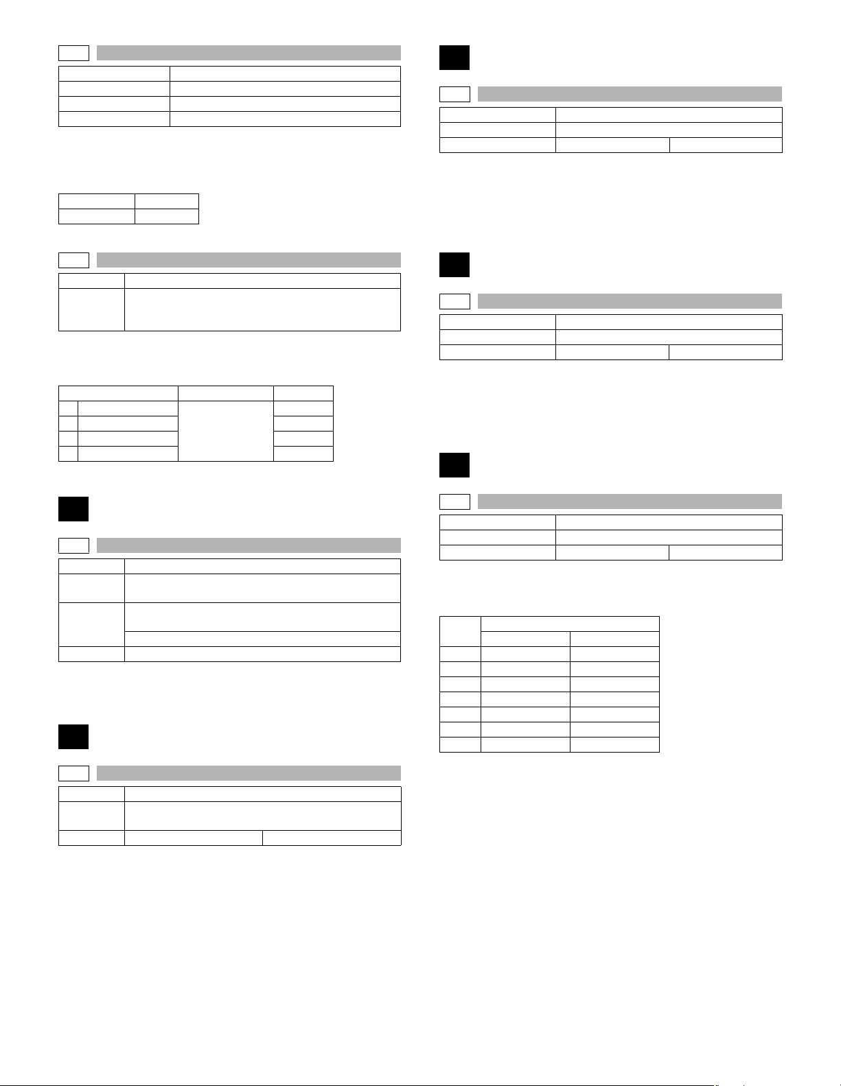
9-4
Purpose Operation test/check
Function (Purpose) Duplex motor RPM setting
Section Duplex
Item Operation
Operation/procedure
Enter the set value with the 10-key.
When the duplex motor setting is made, the duplex 2motor is also set
accordingly.
Setting range 1-13
Default 5
16
16-0
Purpose Clear/Cancel (Trouble etc.)
Function (Purpose) Used to cancel the self-diag U2 trouble.
Item Trouble Error
Operation/procedure
1. Press the [START] key.
2. When “1: YES” is selected, U2 trouble is canceled.
(When “2: NO” is selected, the simulation is canceled.)
9-5
Purpose Adjustment
Function
(Purpose)
Operation/procedure
1. Touch the item to set.
2. Enter the set value with the 10-key, and press the [START] key.
1 145mm/s
2 122mm/s 18
3 RIGHT 145mm/s 50
4 RIGHT 122mm/s 50
Used to adjust the timing of switching from normal
rotation to reverse rotation or from reverse rotation to
normal rotation of the duplex motor.
Item Installation range Default
18
18-76
10
10-0
Purpose Operation test/check
Function
(Purpose)
Section
Item Operation
Operation/procedure
Press the [START] key and operate the toner motor for 30 sec.
Used to check the operation of the toner motor and its
control circuit.
Image process
(Photoconductor/Developing/Transfer/Cleaning)
Developer/Toner hopper
14
14-0
Purpose Clear/Cancel (Trouble etc.)
Function
(Purpose)
Item Trouble Error
Operation/procedure
1. Press the [START] key.
2. When “1: YES” is selected, troubles other than U2 and PF are canceled. (When “2: NO” is selected, the simulation is canceled.)
Used to cancel excluding the self-diag U2/PF troubles.
17
17-0
Purpose Cancel (Trouble, etc)
Function (Purpose) Used to cancel the self diag “PF” trouble.
Item Trouble Error
Operation/Procedure
1. Press the [START] key.
2. When “1: YES” is selected, PF trouble is canceled. (When “2: NO”
is selected, the simulation is canceled.)
21
21-1
Purpose Setting
Function (Purpose) Used to set the maintenance cycle.
Item Specifications Counter
Operation/procedure
1. Enter the set value with the 10-key.
2. Press the [START] key.
Item
05K 5K
1 10K 10K
2 20K 50K
3 25K 75K
4 50K 100K
5 75K (Default) 150K (Default) *
6 FREE FREE
* When selecting 150K, maintenance message is displayed by imple-
menting the following conditions.
• Maintenance count = 150K.
• DV count = 100K
• DR count = 100K
* When maintenance message is displayed, replace consumption part
reaching the number of sheets of maintenance, then clear the
replaced part's counter only.
26cpm 31cpm
Content
AR-5726/5731 SIMULATION 6 - 12
Page 41
22
22-1
Purpose
Function
(Purpose)
Item Counter
Operation/procedure
Each counter is displayed.
TOTAL Total counter
MAINTENANCE Maintenance counter
DEVE Developer counter
DRUM Drum counter
COPY Copy counter
PRINTER Printer counter
IMC IMC counter
DUPLEX Duplex counter
OTHERS The other counters
FAX SEND FAX Send counter
FAX RCV FAX receive counter
FAX OUTPUT FAX print counter
DEVE RANGE Developer traveling distance counter
DRUM RANGE Drum traveling distance counter
DEVE ROLL Developer rotation counter (K)
DRUM ROLL Drum rotation counter (K)
DEVE LIFE Developer life meter (%)
DRUM LIFE Drum life meter (%)
Adjustment/setting/operation data output/check
(display/print)
Used to check the counter value of each section.
(Jam cause code)
Item Jam contents
TRAY1 1st tray pick-up miss
TRAY2 2nd tray pick-up miss
TRAY3 3rd tray pick-up miss
TRAY4 4th tray pick-up miss
BPT Multi manual feed pick-up miss
PPD1_ND Paper-in sensor lead edge jam
PPD1_ST Paper-in sensor rear edge jam
PPD1_DUP Paper-in sensor reverse jam
PPD2_ND Duplex sensor lead edge jam
PPD2_ST Duplex sensor rear edge jam
PPD_PRI PS time out jam
POD3_ND Right paper exit lead edge jam
POD3_ST Right paper exit rear edge jam
POD2_ND Upper tray paper exit lead edge jam
POD2_ST Upper tray paper exit rear edge jam
POD1_ND Lower tray paper exit lead edge jam
POD1_ST Lower tray paper exit rear edge jam
PINT_SHORT Abnormality between PS papers.
PFD2_ND 2nd paper pass lead edge jam
PFD2_ST 2nd paper pass rear edge jam
PFD3_ND 3rd paper pass lead edge jam
PFD3_ST 3rd paper pass rear edge jam
PFD4_ND 4th paper pass lead edge jam
PFD4_ST 4th paper pass rear edge jam
SIZE_SHORT Duplex short scale error
FPPD1_N Finisher entry port sensor not-reached jam
FPPD1_S Finisher entry port sensor remaining jam
FSTPD_S Finisher paper exit remaining jam
FSTPLJ Finisher staple jam
22-2
Purpose
Function
(Purpose)
Item Trouble
Operation/procedure
Each counter data are displayed.
PAPER JAM JAM counter
SPF JAM RSPF JAM counter
TROUBLE Trouble counter
The counter display is in 7 digits.
22-3
Purpose
Function
(Purpose)
Item Trouble Mis-feed
Operation/procedure
The misfeed history is displayed in the sequence of recentness by the
name of sensors and detectors. Max. 40 items of information can be
stored in memory. (The old ones are deleted sequentially.) The trouble
section may be determined by the data.
Adjustment/setting/operation data output/check
(display/print)
Used to check the total numbers of misfeed and
troubles. (When the number of misfeed is considerably
great, it is judged as necessary for repair. The misfeed
rate is obtained by dividing this count value with the
total counter value.)
Adjustment/setting/operation data output/check
(display/print)
Used to check the misfeed positions and the number of
misfeed at each position. (When the number of
misfeed is considerably great, it can be judged as
necessary for repair.)
22-4
Purpose
Function
(Purpose)
Item Trouble
Operation/procedure
The trouble error codes are displayed in the sequence of the latest one
first. Max. 40 items of information are stored. (Older ones are deleted
in sequence.) The machine condition can be estimated by this data.
22-5
Purpose Adjustment/Setting/Check
Function
(Purpose)
Item Software
Operation/procedure
Used to display the ROM version of each section.
[Display example]
ROM version 1.250
The display of the protocol monitor and the soft SW follows this display.
S/N Machine serial number
MCU Main Control Unit
IMC IMC
OPE Panel + Panel label code
PRINTER
NIC
FINISHER
FAX
If it is not installed, “- - - - - - - - - -” is displayed.
Adjustment/setting/operation data output/check
(display/print)
Used to check the total trouble (self diag) history.
Used to check the ROM version of each unit (section).
→ [1.25] (up to 2 decimal places)
PRINTER
NIC
FINISHER
FAX
AR-5726/5731 SIMULATION 6 - 13
Page 42
Panel
display
JPN Japan Japanese, American English, English
EFS
EEU
NEU
CHN SOCC
TWN Taiwan
ARB
FAS Ira n
22-6
Purpose
Function
(Purpose)
Item Data Setting/adjustment data
Operation/Procedure
(Initial screen)
The currently set value is highlighted beside the adjustment item.
1. Select the adjustment item with the 10-key.
2. Press the [START] key.
3. Select the paper feed tray and the print density.
4. Press the [START] key.
After canceling a jam (After picking up, the [C] key is invalid.)
When the other information is repeatedly printed, the display may show
the message, “Remove original from original table.” However, the
operation is performed normally.
1 ALL All lists group print (Default)
2 SYSTEM SETTING System setting information list
3
4 AUDITOR NO. Department number list
5
6 FAX SIM SETTING*1
* When the IMC board is not installed, key input is disabled.
* Duplex print cannot be made.
* For the FAX SIM setting list, the display and the operating proce-
dures differ.
Note: When the simulation is canceled, the display returns to the origi-
Destination Panel software support language
SEC
SECL
SUK
SCA/SCNZ
Distributor
area
SEEG/
SEA/East
Europe,
etc.
SEF/
SEES/
SEIS/SEN,
etc.
Saudi
Arabia
Adjustment/setting/operation data output/check
(display/print)
Used to print each system setting, the account
information, and the machine adjustment values.
The display is shifted to the copy menu and the set value is stored.
Copying is started.
Item Content
ACCOUNTING
COUNTERS
MACHINE SIM
SETTING
nal state but the machine is not reset.
American English, English, French, Spanish,
Brazilian Portuguese
English, German, Polish, Czech, Hungarian,
Greek, Turkish, Russian, French, Italian,
Slovak
English, German, French, Spanish, Dutch,
Italian, Portuguese, Swedish, Norwegian,
Finnish, Danish
Simplified Chinese, American English,
English, Japanese
Traditional Chinese (Local support),
American English, English
American English, English, French, Spanish,
Hebrew (Local support), Arabic
English, Arabic, Persian, American English,
French, Spanish
List of total number of prints
Machine simulation setting list
FAX simulation setting list (Only when
the FAX board is installed. The display
does not go to the print data transfer
display, but to the FAX SIM menu.)
22-7
Purpose User data output/Check (Display/Print)
Function
(Purpose)
Item Data User data
Operation/procedure
Used to display the administrator password.
22-8
Purpose
Function
(Purpose)
Item Counter
Operation/procedure
Each counter is displayed.
SPF
SCAN
STAPLE
The counter display is in 7 digits.
22-9
Purpose
Function
(Purpose)
Section Paper feed
Item Counter
Operation/procedure
Used to display each paper feed counter.
BYPASS
TRAY1
TRAY2
TRAY3
TRAY4
The counter display is in 7 digits.
22-10
Purpose
Function
(Purpose)
Item Specifications Option
Operation/procedure
The detected machine composition is displayed.
(The job separator cannot be detected. Based on SIM 26-1 setting.)
SPEED
DF
OUTPUT
CASETTE1
CASETTE2
IMC MEM
PRINTER
PS3
NIC
SCANNER
FAX
FAX MEM
HAND SET
USB HOST NONE/USB HOST
Used to display of the administrator password.
Adjustment/setting/operation data output/check
(display/print)
Used to display the original, staple counter.
RSPF counter
Scan counter
Stapler counter
Adjustment/setting/operation data output/check
(display/print)
Used to check the number of use of each paper feed
section. (the number of prints)
Manual feed counter
Tray 1 counter
Tray 2 counter
Tray 3 counter
Tray 4 counter
Adjustment/setting/operation data output/check
(display/print)
Used to check the system configulation.
Item Display items
26CPM/31CPM
NONE/[1: RSPF]
NONE/[2: Finisher]/[3: Job separator]
NONE/[4: One-step paper feed unit]
NONE/[5: Two-step paper feed unit]
NONE/Expansion memory capacity (MB)
NONE/[6: PRINTER]
NONE/[7: PS3]
NONE/[8: NIC]
NONE/[9: SCANNER]
NONE/[10: FAX]
NONE/Memory capacity (MB)
NONE/[11: Handset]
AR-5726/5731 SIMULATION 6 - 14
Page 43
Item Display items
ICCARDR/W NONE/MX-ECX2
NONE: When it is not installed, “- - - - - - - - - -” is displayed.
[ ]: Shows the product code in the list below.
No. Item Model code
1 RSPF MX-RP10
2 Finisher MX-FN13
3 Job separator MX-TR11
4 1 tray paper feed unit MX-DE10 (*1)
5 2 tray paper feed unit MX-DE11 (*1)
6 PRINTER MX-PB12
7 PS3 MX-PK10
8 NIC STANDARD (Only SoftNic)
9 SCANNER MX-NSX1
10 FAX AR-FX7
11 Handset AR-HN4
*1: The number of installed units is displayed beside the model code.
For the tray, only the option tray is displayed.
22-11
Purpose
Function
(Purpose)
Section FAX
Item Counter
Operation/procedure
Used to display the FAX send/receive counter.
FAX SEND PAGE/TIME FAX send page and time
FAX RECEIVE PAGE/TIME FAX receive page and time
FAX OUTPUT FAX output (number of print)
The counter display is in 8 digits.
Note: Executable only when the FAX is installed.
22-12
Purpose
Function
(Purpose)
Section RSPF
Item Trouble Misfeed
Operation/procedure
Used to display the RSPF jam history data sequentially from the latest
one.
Forty RSPF jam histories are displayed sequentially from the latest.
Error code Name Sensor name
DFD_ND
DFD_ST
RDD_ND
RDD_ST
JAM_REV
ORG_SHORT
Adjustment/setting/operation data output/check
(display/print)
Used to display the FAX send/receive counter
(FAX reception and print counter).
Adjustment/setting/operation data output/check
(display/print)
Used to check the misfeed positions and the number of
misfeed at each position.
(When the number of misfeed is considerably great, it
can be judged as necessary for repair.)
Paper Reached/
Not Reached to
the sensor
RSPF paper in lead
edge jam
RSPF paper in rear
edge jam
RSPF paper out
lead edge jam
RSPF paper out
rear edge jam
RSPF duplex
reverse jam
RSPF short size
error
SPF P-IN
sensor
SPF P-IN
sensor
SPF P-IN
sensor
SPF P-OUT
sensor
SPF P-IN
sensor
SPF P-IN
sensor
Not Reached
Reached
Reached,
P_OUT Not
Reached
Reached, P_IN
passed (OFF)
Not Reached
(Paper after
reversing)
Passed (OFF at
JAM)
Error code Name Sensor name
SPF P-OUT
ORG_LONG
22-13
Purpose
Function
(Purpose)
Item Specifications
Operation/Procedure
Used to display the CRUM type.
Item Content
00 Not fixed.
01 AR-A
02 AR-B
03 AR-C
04 China
05 Japan
99 Conversion completed.
22-19
Purpose
Function
(Purpose)
Section Network scanner
Item Counter
Operation/procedure
Used to display the scanner counter.
SCANMODE
The counter display is in 7 digits.
RSPF long size
error
Adjustment/setting/operation data output/check
(display/print)
Used to display the CRUM type.
Adjustment/setting/operation data output/check
(display/print)
Used to display the scanner counter in the network
scanner mode.
Scanner mode counter
sensor
SPF P-IN
sensor
Paper Reached/
Not Reached to
the sensor
Reached
Reached
24
24-1
Purpose Data clear
Function
(Purpose)
Section Memory
Item Counter
Operation/procedure
Jam/trouble counter is cleared individually. (The history of each
counter is deleted when clearing)
1. Select the counter to be cleared with the 10-key.
2. Press the [START] key.
The confirmation menu is shown.
3. Select “1: YES.”
1: YES (Cleared)
2: NO (Not cleared) (Default)
JAM
1
SPF JAM
2
3
TROUBLE
Used to clear the misfeed counter, the misfeed history,
the trouble counter, and the trouble history. (The
counters are cleared after completion of maintenance.)
Item Content
JAM counter/JAM history
RSPF JAM counter/RSPF JAM history
Trouble counter/Trouble history
AR-5726/5731 SIMULATION 6 - 15
Page 44
24-2
Purpose Data clear
Function
(Purpose)
Section Paper feed
Item Counter
Operation/procedure
Used to clear each paper feed counter individually.
1. Select the counter to be cleared with the 10-key.
2. Press the [START] key. The confirmation menu is shown.
3. Select “1: YES.”
1: YES (Cleared)
2: NO (Not cleared) (Default)
Item Content
1 BYPASS
2TRAY1
3TRAY2
4TRAY3
5TRAY4
24-3
Purpose Data clear
Function
(Purpose)
Section Transport/Finisher
Item Counter
Operation/procedure
Used to clear the original and staple counters individually.
1. Select the counter to be cleared with the 10-key.
2. Press the [START] key.
The confirmation menu is shown.
3. Select “1: YES.”
1: YES (Cleared)
2: NO (Not cleared) (Default)
1
SPF
2
SCAN
STAPLE
3
24-4
Purpose Data clear
Function (Purpose) Used to reset the maintenance counter.
Item Counter
Operation/procedure
1. Press the [START] key. The confirmation menu is shown.
2. Select “1: YES.”
1: YES (Cleared)
2: NO (Not cleared) (Default)
Used to clear the number of use (the number of prints)
of each paper feed section.
Manual feed counter
Tray 1 counter
Tray 2 counter
Tray 3 counter
Tray 4 counter
Used to clear the number usage data of the stapler,
RSPF, and scanning.
Item Content
RSPF counter
Scan counter
Stapler counter
24-5
Purpose Data clear
Function
(Purpose)
Section Image process
Item Counter Developer
Operation/procedure
After execution of SIM25-2, this counter is cleared.
1. Press the [START] key.
The confirmation menu is shown.
2. Select “1: YES.”
1: YES (Cleared)
2: NO (Not cleared) (Default)
24-6
Purpose Data clear
Function (Purpose) Used to clear the copy counter.
Item Counter Copier
Operation/procedure
1. Press the [START] key.
The confirmation menu is shown.
2. Select “1: YES.”
1: YES (Cleared)
2: NO (Not cleared) (Default)
24-7
Purpose Data clear
Function
(Purpose)
Section
Item Counter
Operation/procedure
1. Press the [START] key.
The confirmation menu is shown.
2. Select “1: YES.”
1: YES (Cleared)
2: NO (Not cleared) (Default)
24-9
Purpose Data clear
Function
(Purpose)
Section Printer
Item Counter Printer
Operation/procedure
1. Select the counter to be cleared with the 10-key.
2. Press the [START] key.
The confirmation menu is shown.
3. Select “1: YES.”
1: YES (Cleared)
2: NO (Not cleared) (Default)
1 PRINTER
2IMC
3DUPLEX
4OTHERS
Used to reset the developer counter. (The developer
counter of the DV unit which is installed is reset.)
(Photoconductor/Developing/Transfer/Cleaning)
Developer/Toner hopper
Used to clear the OPC drum (membrane decrease)
correction counter. (This simulation is executed when
the OPC drum is replaced.)
Image process
(Photoconductor/Developing/Transfer/Cleaning)
Photo conductor
Used to clear the printer counter and other counters.
Item Content
Printer counter
IMC counter
DUPLEX counter
The other counters
AR-5726/5731 SIMULATION 6 - 16
Page 45
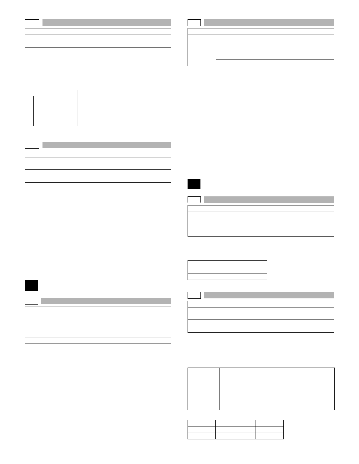
24-10
Purpose Data clear
Function (Purpose) FAX counter data clear
Section FAX
Item Counter
Operation/procedure
1. Select a counter to be cleared with the 10 key.
2. Select “1: YES.”
1: YES (Cleared)
2: NO (Not cleared) (Default)
Item Content
FAX SEND
1
(PAGE & TIME)
FAX RECEIVE
2
(PAGE & TIME)
3 FAX OUTPUT FAX output (number of prints)
Note: Executable only when the FAX is installed.
24-15
Purpose Data clear
Function
(Purpose)
Section Scanner section
Item Counter
Operation/procedure
1. Press the [START] key.
The confirmation menu is shown.
2. Select “1: YES.”
1: YES (Cleared)
2: NO (Not cleared) (Default)
The scanner mode counter and the number of send of the scanner are
cleared.
* The simulation to perform communication with the PCL is inhibited
until Notice Page storing is completed. (Only when the serviceman
call error occurs.)
* When in other than the serviceman call error, entering the simulation
is not allowed from the system check display.
Used to clear the scanner counter in the network
scanner mode.
FAX send page and time
FAX receive page and time
25-2
Purpose Setting
Function
(Purpose)
Section
Operation/procedure
After execution, the developer counter is cleared.
1) Open the cover with the power OFF.
2) Turn on the power. (Since the cover is open, the machine does not
perform initializing.)
3) Execute the simulation.
4) Enter SIM 25-2. ([25]
5) Close the cover just before starting the simulation.
6) Press the [START] key.
The main motor rotates. After stirring for 3 min, the toner density
control sensor value is sampled 16 times, and the average value is
stored.
When “EE-EU” or “EE-EL” after completion, an error display is shown.
Note: After completion of execution, be sure to press the [CA] key to
cancel the simulation.
Used to make the initial setting of toner concentration
when replacing developer.
Image process
(Photoconductor/Developing/Transfer/Cleaning)
Developer/Toner hopper
→ [START] key → [2] → [START] key)
26
26-1
Purpose Setting
Function
(Purpose)
Item Specifications Option
Operation/procedure
1. Select the set value with the 10-key.
2. Press the [START] key.
Set value Connection option
0 None (default)
1 Job separator provided.
Used to set whether the job separator is installed or
not. (Since this cannot be detected by hardware
detection, it is set in this simulation.)
25
25-1
Purpose Operation test/check
Function
(Purpose)
Section DRIVE
Item Operation
Operation/procedure
1. Press the [START] key.
The main motor rotates to start monitoring the toner density control
sensor. (3min operation)
* Even in toner end error, if there is no other error (including cover
open) after turning on the power, this simulation can be performed.
Used to check the operation of the main drive
(excluding the scanner section) and to check the
operation of the toner concentration sensor. (The toner
concentration sensor output can be monitored.)
AR-5726/5731 SIMULATION 6 - 17
26-2
Purpose Setting
Function
(Purpose)
Section Paper feed
Item Specifications
Operation/procedure
1. Select the item with the 10-key and press the [START] key.
Used to set the automatic size detection.
2. Set whether automatic detection of paper size is made or not with
the 10-key.
1:B4/LG,FC
2:A4<->LT
8.5” x 13” detection valid/invalid setup
Set value Setup Remarks
0 Detection invalid Default
1 Detection valid
Used to set whether the automatic detection of paper
size is made or not.
Setting to detect B4/Legal as FC
0: B4 legal is detected as B4 legal. (Default)
1: B4 legal is detected as FC.
This setup detects Letter as A4 in the inch series and
A4 as Letter in the AB series.
0: Detection disable (Default)
1: Detection valid
Page 46
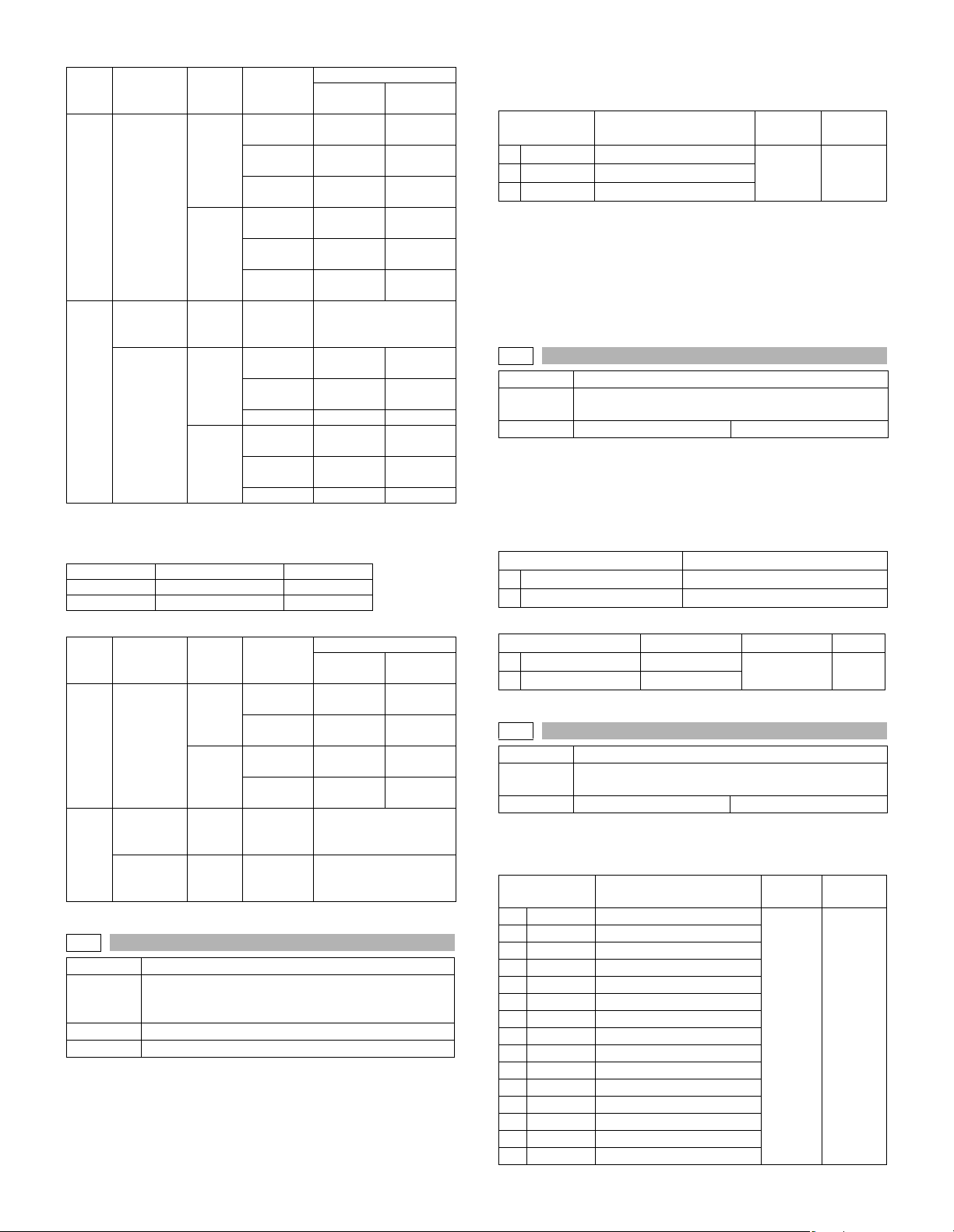
Detection size when 8.5” x 13” document/paper is used.
Employed
unit
Document
Docu
table/
ment
RSPF
Machine
paper feed
tray
Paper
Manual
paper feed
tray
A4/LT (8.5” x 11”) detection enable/disable setup
In the inch series, Letter is detected as A4; in the AB series, A4 is
detected as Letter.
Set value Setup Remarks
0 Detection invalid Default
1 Detection valid
Detection size when A4/LT (8.5” x 11”) document/paper is used.
Employed
unit
Document
Docu
table/
ment
RSPF
Machine
paper feed
tray
Paper
Manual
paper feed
tray
26-3
Purpose Setting
Function
(Purpose)
Section Auditor
Item Specifications
Destina
AB
series
Inch
series
All
destina
tions
AB
series
Inch
series
Destina
AB
series
Inch
series
All
destina
tions
All
destina
tions
Used to set the specifications of the auditor.
Setting must be made depending on the use condition
of the auditor.
tion
tion
Document
size
FC
(8.5” x 13”)
LG
(8.5” x 14”)
B4 B4
FC
(8.5” x 13”)
LG
(8.5” x 14”)
B4
– Set with system setting.
FC
(8.5” x 13”)
LG
(8.5” x 14”)
B4 B4 B4
FC
(8.5” x 13”)
LG
(8.5” x 14”)
B4 B4 B4
Document
size
A4 A4
LT
(8.5” x 11”)
A4
LT
(8.5” x 11”)
– Set with system setting.
–
Set value
0
(Invalid)
B4
B4
LG
(8.5” x 14”)
LG
(8.5” x 14”)
WLT
(11” x 17”)
LG
(8.5” x 14”)
LG
(8.5” x 14”)
LG
(8.5” x 14”)
LG
(8.5” x 14”)
(Invalid)
A4
(8.5” x 11”)
(8.5” x 11”)
Regardless of the
simulation setup.
(8.5” x 13”)
(8.5” x 13”)
(8.5” x 13”)
(8.5” x 13”)
(8.5” x 13”)
(8.5” x 13”)
(8.5” x 13”)
(8.5” x 13”)
(8.5” x 13”)
Set value
0
(8.5” x 11”)
(8.5” x 11”)
LT
LT
1
(Valid)
FC
FC
FC
FC
FC
WLT
(11” x 17”)
FC
FC
FC
FC
1
(Valid)
LT
LT
A4
A4
Operation/procedure
Select the mode corresponding to the auditor specification mode with
the 10-key.
Item Content
0
P10
VENDOR
OTHER
2
When “1: VENDOR (Coin vendor mode)” is set, the following three
items of system setting are changed.
1) Set the LCD backlight change inhibit to “1: OFF (Enable).”
2) When SIM 26-6 destination setting is set to “0: Japan,” duplex copy
inhibit setting must be set to “0: ON (Inhibit).”
3) Set the sort automatic selection to “0: OFF (Disable).”
26-5
Purpose Setting
Function
(Purpose)
Item Specifications Counter
Operation/procedure
Used to set the count up number (1 or 2) when an A3/WLT paper
passes through.
For the drum counter and the developer counter, double count is
employed unconditionally.
(Target counter selection)
TOTAL COUNTER
1
MAINTENANCE COUNTER
2
Used to set the count up number of the selected counter.
SINGLE COUNT
1
DOUBLE COUNT
2
26-6
Purpose Setting
Function
(Purpose)
Item Specifications Destination
Operation/procedure
Select the destination with the 10-key.
By changing the destination, some other setting items may be changed.
Item Content
0
JAPAN
SEC
1
2
SECL
SEEG
3
4
SUK
5
SCA
SEF
6
7
INEG
8
ABEG
INEF
9
10
ABEF
11
CHINESE
TA I WA N
12
13
SEEG2
14 TAIWAN2 Taiwan China
Built-in auditor mode
Coin vendor mode
Others
Used to set the count mode of the total counter and the
maintenance counter.
Item Content
Total counter
Maintenance counter
Item Content Setting range Default
Single count
Double count
Used to set the specifications depending on the
destination.
Japan
SEC
SECL
SEEG
SUK
SCA
SEF
EX inch series
EX AB series
EX inch series (FC)
EX AB series (FC)
China
Taiwan AB
SEEG2
Setting
range
0-2 01
1-2 2
Setting
range
0-14 0
Default
Default
AR-5726/5731 SIMULATION 6 - 18
Page 47
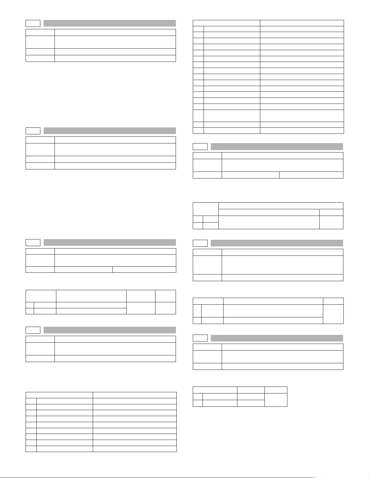
26-12
Purpose Setting
Function
(Purpose)
Used to input the Software Key for E-MAIL RIC.
Section E-MAIL RIC
Item Specifications
Operation/procedure
The current setup is displayed with ON or OFF.
Enter an input (20 digits) of the E-MAIL RIC soft key with the 10-key
and press the [START] key, and the collating result is displayed with
OK or NG.
After canceling the simulation, if OK, the E-MAIL RIC function is
enable; if NG, the E-MAIL RIC function is disabled.
This setting must be reset after the simulation cancel.
26-14
Purpose Setting
Function
(Purpose)
Used to input the Software Key for the PS extention kit.
Section Printer
Item Specifications
Operation/procedure
The current setup is displayed with ON or OFF.
Enter an input (20 digits) of the PS expansion kit soft key with the 10key and press the [START] key, and the collating result is displayed
with OK or NG.
After canceling the simulation, if OK, the PS expansion kit function is
enable; if NG, the PS expansion kit function is disabled.
This setting must be reset after the simulation cancel.
Note: Executable only when the PCL/PS3 is installed.
9 PORTUGUESE
Item Remarks
10 TURKISH
11 GREEK
12 POLISH
13 HUNGARIAN
14 CZECH
15 RUSSIAN
16 FINNISH
17 NORWEGIAN
18 DANISH
19 CHINESE
20 TAIWANESE Traditional Chinese supported locally
21 SLOVAK
22 HEBREW Supported locally
BRAZILIAN
23
PORTUGUESE
24 ARABIC
25 FARSI
26-30
Purpose Setting
Function
(Purpose)
Used to set ON/OFF of the heater lamp slow-up control
conforming to the CE mark control.
Item Specifications Operation mode (Common)
Operation/procedure
Input the set value with the 10-key and press the [START] key.
This setup varies in connection with SIM 26-6 (Destination setup).
Item
0
OFF
ON
1
U.S.A, Canada, Australia, France, Taiwan Others
Default
01
26-18
Purpose Setting
Function
(Purpose)
Used to set enable/disable of toner save operation.
Item Specifications Operation mode (Common)
Operation/procedure
Input the set value with the 10-key and press the [START] key.
Item Content
OFF
0
ON
1
Disable
Enable
Setting
range
0-1 1
Default
26-22
Purpose Setting
Function
(Purpose)
Used to set the specification (language display) for the
destination.
Item Specifications
Operation/procedure
Select the display language with the 10-key, and press the [START]
key.
This setup varies in connection with SIM 26-6 (Destination setup).
Item Remarks
0 JAPANESE
1 ENG.US
2 ENG.UK
3 FRENCH
4GERMAN
5ITALY
6 DUTCH
7SWEDISH
8SPANISH
26-35
Purpose Setup
Function
(Purpose)
Used to set whether the same continuous troubles are
displayed as one trouble or the series of troubles with
SIM 22-4 when the same troubles occur continuously.
Item Specifications
Operation/procedure
Enter the set value with 10-key, and press [START] key.
Item Content Default
0
1
ONCE
ANY
When two or more troubles occur, only one is
registered.
All the troubles occurred are registered.
26-36
Purpose Setting
Function
(Purpose)
Used to set whether the machine is stopped or not
when the maintenance counter life is expired.
Item Operation
Operation/procedure
Input the set value with the 10-key and press the [START] key.
Item Content Default
0STOP Stop
1 NON STOP Non stop
1
0
AR-5726/5731 SIMULATION 6 - 19
Page 48
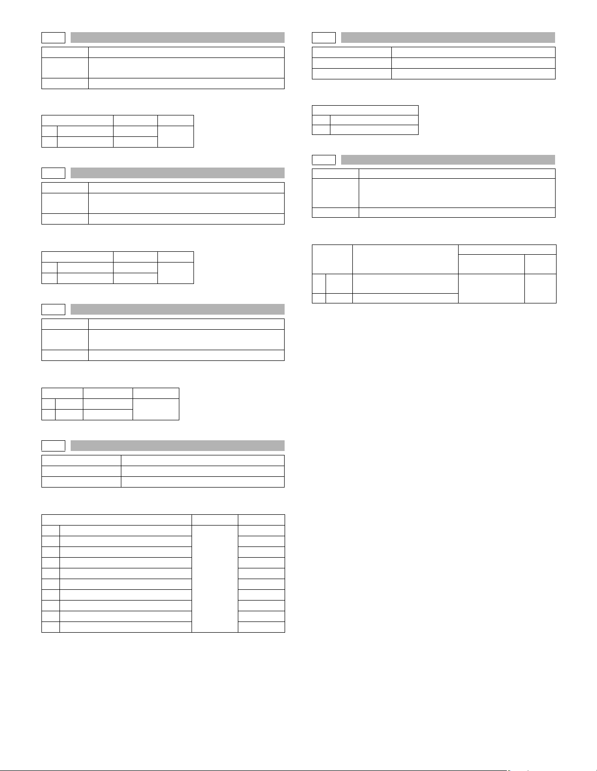
26-37
Purpose Setting
Function
(Purpose)
Used to set whether the machine is stopped or not
when the developer counter life is expired.
Item Operation
Operation/procedure
Input the set value with the 10-key and press the [START] key.
Item Content Default
0STOP Stop
1 NON STOP Non stop
1
26-38
Purpose Setting
Function
(Purpose)
Used to set whether the machine is stopped or not
when the drum counter life is expired.
Item Operation
Operation/procedure
Input the set value with the 10-key and press the [START] key.
Item Content Default
0STOP Stop
1 NON STOP Non stop
1
26-50
Purpose Setting
Function
(Purpose)
Used to set ON/OFF of the black and white reversion
function.
Item Operation
Operation/procedure
Enter the set value with the 10-key, and press the [START] key.
Item Content Default
0ON
1OFF
Enable 1 (U.K.)
Disable
0 (Others)
26-57
Purpose Setting
Function (Purpose) Used to set the model code.
Item Operation
Operation/procedure
Input the set value with the 10-key and press the [START] key.
Item
1 AR-5726
2 AR-5731
26-60
Purpose Setting
Function
(Purpose)
Used to set enable/disable of the FAX mode key when
FAX is not installed. (When FAX is installed, the FAX
mode is enabled regardless of this setup.)
Item Operation
Operation/procedure
Input the set value with the 10-key and press the [START] key.
Default
Item Content
0ON
Effective (The message with
FAX uninstalled is displayed.) 0 1
U.S.A, Canada,
U.K., Australia
Others
1 OFF Disable (Error Beep)
This setup varies in connection with SIM 26-6 (Destination setup).
26-56
Purpose Setting
Function (Purpose) Gamma life correction setting
Item Operation
Operation/procedure
Sets enable/disable of the gamma life correction function.
Item Set value Default
1 AE (Japan)
2 AE (Ex Japan) 0
3Text 1
4 Text/Photo 1
5 Photo (Error diffusion) 1
6 Photo (Dither) 1
0: Disable
1: Enable
7 T/S AE (Japan) 0
8 T/S AE (Ex Japan) 0
9 T/S Text 1
10 T/S Text/Photo 1
0
AR-5726/5731 SIMULATION 6 - 20
Page 49
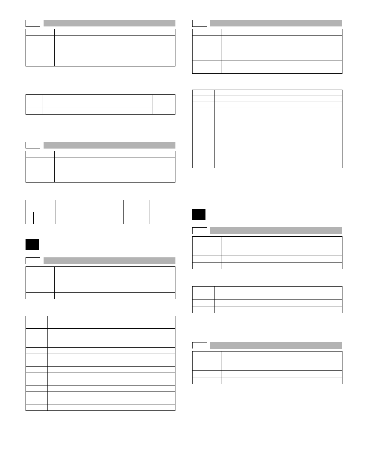
26-71
Purpose Setting
In the power save time setting, the pre-heat (pre-heat
Function
(Purpose)
Operation/procedure
Select the short time setup or the long time setup of the pre-heat time
and the auto power shut off time with the 10-key, and press the
[START] key.
Item Content Default
1 Preheat: 1min, auto power shut off: 1min
2 Preheat: 5min, auto power shut off: 30min
Note: When the sub code 71 is entered to display the setting menu,the
default values are always displayed. (However,the default time is
not always set.)
26-72
Purpose Setting
Function
(Purpose)
Operation/procedure
Input the set value with the 10-key and press the [START] key.
Item Content
0 OFF Letterhead paper is not set.
1 ON Letterhead paper is set.
mode setting) and the auto power shut off time can be
set to the short time setup (pre-heat: 1 min, auto power
shut off: 1 min) and the long time setup (pre-heat:
5min, auto power shut off: 30min).
1
The letterhead support is set.
When “Letterhead paper setting” is selected, the set
value of SIM 26-46 (Image output direction setting) is
set to “Setting Enable” accordingly.
Setting
range
0-1 0
Default
30-2
Purpose Operation test/check
Used to display the status of the sensors attached to
Function
(Purpose)
Section Paper feed
Item Operation
Operation/procedure
The active sensors and detectors are highlighted.
PED1
LUD1
CD1
PED2
LUD2
CD2
PFD2
DSWR2
MPED
MPLS1
MPLS2
MPLD1
MPLD2
Width detection size of the manual feed tray (one of them is displayed.)
A4/A3, LT/WLT, B5/B4, INV/LTR, A5/A4R, B5R, POSTCARD, EXTRA,
8K/16K
(At detection, highlighted)
the standard tray and the manual feed tray. (Use SIM
4-2 for the option trays.)
The sensor of an uninstalled tray is not displayed.
1st tray paper empty sensor
1st tray paper upper limit detection sensor
1st tray empty sensor
2nd tray paper empty sensor
2nd tray paper upper limit detection sensor
2nd tray empty sensor
2nd tray paper pass sensor
2nd tray right door detection sensor
Manual tray paper empty detection
Manual tray length detection 1
Manual tray length detection 2
Manual feed paper length detection 1
Manual feed paper length detection 2
40
30
30-1
Purpose Operation test/check
Function
(Purpose)
Section Others
Item Operation
Operation/procedure
The active sensors and detectors are highlighted.
PPD1H
PPD1L
PPD2
POD1
DVCH
DRST
DSWR1
SFTHP
POD2
TOPF
DSWR0
LOEMP
DUP2
POD3
PTOPF
Used to display the sensor status attached to the
machine.
PS paper detection 1 sensor
PS paper detection 2 sensor
Fusing paper sensor
1st paper exit paper out sensor
Developing cartridge detection sensor
Drum intial detection sensor
Interlock switch (side door)
Shifter home position sensor
2nd paper exit paper out sensor
2nd paper exit full detection sensor
2nd paper exit cover open/close detection sensor
1st paper exit empty detection sensor
Reverse path paper sensor
Right paper exit sensor
Right paper exit full sensor
40-1
Purpose Operation test/check
Function
(Purpose)
Section Paper feed
Item Operation
Operation/procedure
The active sensors and detectors are highlighted.
MPLS1
MPLS2
MPLD1
MPLD2
Width detection size of the manual feed tray (one of them is displayed.)
A4/A3, LT/WLT, B5/B4, INV/LTR, A5/A4R, B5R, POSTCARD, EXTRA,
8K/16K
40-2
Purpose Adjustment
Function
(Purpose)
Section Paper feed
Item Operation
Operation/procedure
The adjustment method is of the 4-point system. Set the guide to Max.
(A3/WLetter) position, A4R/Letter R position, A5R/Invoice R position,
and Min. position for adjustment.
1) Set A3/W Letter and fit the guide, then press the [START] key.
2) Set A4R/LetterR and fit the guide, then press the [START] key.
3) Set to A5R/INVOICE R and fit the guide, then press the [START]
key.
4) Narrow the guide at minimum, press the [START] key.
5) Set the paper detection width (+), and press the [START] key.
Used to check the sensor of the machine manual feed
tray.
Manual tray length detection 1
Manual tray length detection 2
Manual feed paper length detection 1
Manual feed paper length detection 2
Used to adjust the manual paper feed tray paper width
detector detection level.
AR-5726/5731 SIMULATION 6 - 21
Page 50
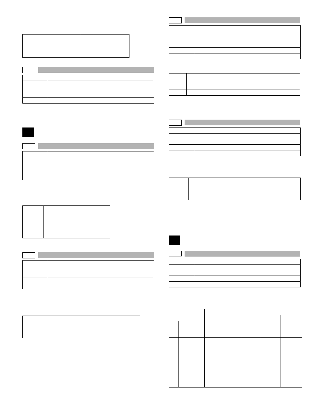
6) Set the paper detection width (–), and press the [START] key.
If “FAILED” is displayed in procedure 1), 2), 3), or 4), it is NG of adjustment. Repeat the adjustment.
Middle position adjustment L
Middle position adjustment S
40-3
Purpose Adjustment
Function
(Purpose)
Section Paper feed
Item Operation
Operation/procedure
The AD conversion value of manual feed width detection is displayed.
The AD conversion value of manual feed width
detection is displayed.
Yes MID-L ADJ.ON
No MID-L ADJ.OFF
Yes NID-S ADJ.ON
No MID-S ADJ.OFF
41
41-1
Purpose Operation test/check
Function
(Purpose)
Section Others
Item Operation
Operation/procedure
The operation status of the sensors and detectors in the original size
detection section are displayed. The active sensors and detectors are
highlighted.
OCSW
PD1 to 5
For AB series, PD1 to 5 is displayed, for inch series, PD1 to 4.
Used to check the document size detection photo
sensor.
Original cover state
Open: Highlighted display
Close: Normal display
Original sensor status
Without original: Normal display
With original: Highlighted display
41-3
Purpose Operation test/check
Function
(Purpose)
Section Others
Item Operation
Operation/procedure
The detection output level of each sensor is displayed in real time.
OCSW
1 to 5 PD sensor detection level (Hexadecimal display)
The value in [ ] shows the threshold value of 20 degree detection
adjustment. (Hexadecimal display)
For AB series, 1 to 5 is displayed, for inch series, 1 to 4.
41-4
Purpose Adjustment
Function
(Purpose)
Section Others
Item Operation
Operation/procedure
Set the OC cover at 20 degrees detection and press the [START] key.
The detection output level of each sensor is displayed in real time.
OCSW
1 to 5 PD sensor detection level (Hexadecimal display)
The value in [ ] shows the threshold value of 20 degree detection
adjustment. (Hexadecimal display)
For AB series, 1 to 5 is displayed, for inch series, 1 to 4.
During execution, [EXECUTING] is highlighted.
Used to check the light reception level and the
detection level of the original size detection photo
sensor.
Original cover state
Open: Highlighted display
Close: Normal display
Used to adjust the detection level of OC 20 degrees.
Original cover state
Open: Highlighted display
Close: Normal display
43
41-2
Purpose Adjustment
Function
(Purpose)
Section Others
Item Operation
Operation/procedure
Place an A3 (or WLT) document on the document table, and press
[START] key with the OC cover open.
The adjustment is performed and the result is displayed.
OCSW
1 to 5 PD sensor detection level (Hexadecimal display)
The value in [ ] shows the threshold value. (Hexadecimal display)
For AB series, 1 to 5 is displayed, for inch series, 1 to 4.
During execution of the simulation, “EXECUTING” is displayed.
Used to adjust the detection level of the document size
photo sensor.
Original cover state
Open: Highlighted display
Close: Normal display
AR-5726/5731 SIMULATION 6 - 22
43-1
Purpose Setting
Function
(Purpose)
Section Fixing (Fusing)
Item Operation
Operation/procedure
1. Touch the item to be set.
2. Enter the set value with the 10-key.
1
2
3
4
Used to set the fusing temperature.
Item Content
Ready
Temp Main
(145)
Ready
Temp Sub
(145)
Ready
Temp Main
(122)
Ready
Temp Sub
(122)
Ready
temperature Main
(145mm/s)
Ready
temperature Sub
(145mm/s)
Ready
temperature Main
(122mm/s)
Ready
temperature Sub
(122mm/s)
Setting
range
150 -
220
150 -
220
150 -
220
150 -
220
Default
(Others) (Europe)
185 190
180 185
175 180
170 175
Page 51
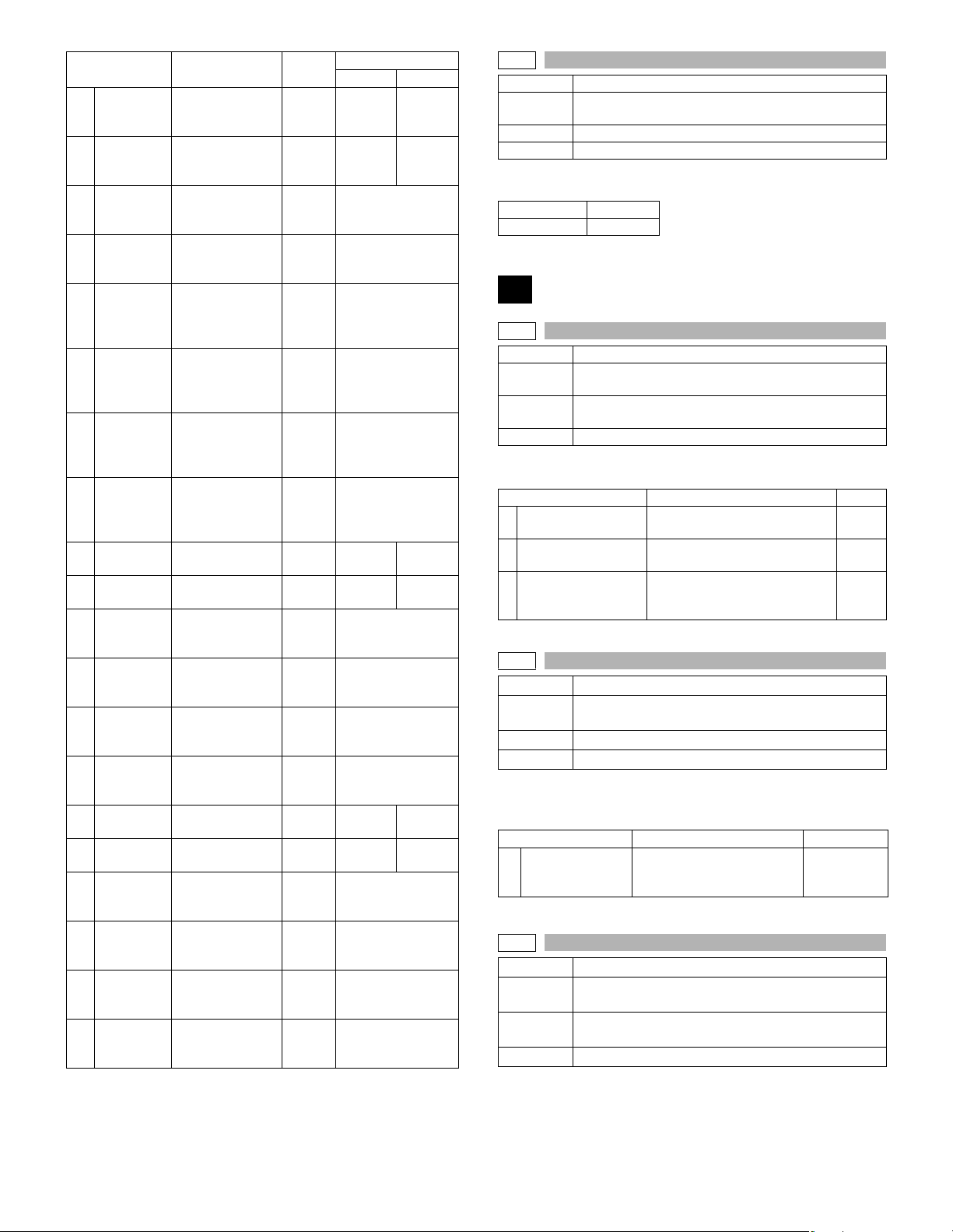
Item Content
WarmUp
5
Target Main
(145)
WarmUp
6
Target Sub
(145)
WarmUp
7
Target Main
(122)
WarmUp
8
Target Sub
(122)
WarmUp
Temp Main
9
(145)
WarmUp
Temp Sub
10
(145)
WarmUp
Temp Main
11
(122)
WarmUp
Temp Sub
12
(122)
600dpi
13
Main (145)
600dpi Sub
14
(145)
POST
15
CARD
Main (145)
POST
16
CARD Sub
(145)
CARDBOA
17
RD Main
(145)
CARDBOA
18
RD Sub
(145)
600dpi
19
Main (122)
600dpi Sub
20
(122)
CARDBOA
21
RD Main
(122)
POST
22
CARD Sub
(122)
POST
23
CARD
(122mm/s)
CARDBOA
24
RD Sub
(122)
Warmup target
temperature Main
(145mm/s)
Warmup target
temperature Sub
(145mm/s)
Warmup target
temperature Main
(122mm/s)
Warmup target
temperature Sub
(122mm/s)
Warmup
complete
temperature Main
(145mm/s)
Warmup
complete
temperature Sub
(145mm/s)
Warmup
complete
temperature Main
(122mm/s)
Warmup
complete
temperature Sub
(122mm/s)
600dpi Main
(145mm/s)
600dpi Sub
(145mm/s)
Postcard Main
(145mm/s)
Postcard Sub
(145mm/s)
Thick paper Main
(145mm/s)
Thick paper Sub
(145mm/s)
600dpi Main
(122mm/s)
600dpi Sub
(122mm/s)
Postcard Main
(122mm/s)
Postcard Sub
(122mm/s)
Thick paper Main
(122mm/s)
Thick paper Sub
(122mm/s)
Setting
range
150 -
220
150 -
220
150 -
220
150 -
220
0 - 40 10
0 - 40 15
0 - 40 10
0 - 40 15
150 -
220
150 -
220
150 -
220
150 -
220
150 -
220
150 -
220
150 -
220
150 -
220
150 -
220
150 -
220
150 -
220
150 -
220
Default
(Others) (Europe)
180 190
180 190
190 195
190 195
175 185
175 185
175
170
200
200
200
200
190
190
190
190
43-10
Purpose Setting
Function
(Purpose)
Section Paper feed
Item Operation
Operation/procedure
Input the set value with the 10-key and press the [START] key.
Setting range 1-99
Default 50
Used to set the paper feed cycle timing when printing
postcards.
44
44-1
Purpose Setting
Function
(Purpose)
Section
Item Operation
Operation/procedure
Enter the set value with the 10-key, and press the [START] key.
ENVIRONMENT
1
ADJ.
2 DUPLEX PRINT ADJ.
ENVIROMENT ADJ
3
(TC)
44-2
Purpose Setting
Function
(Purpose)
Section Image process (Photoconductor)
Item Operation
Operation/procedure
1. Select an item with 10-key, and press [START] key.
2. Enter the setting value, and press [START] key.
GRIDBIAS
1
ADJUST
44-3
Purpose Setting
Function
(Purpose)
Section
Item Operation
Used to make various setups in each mode of process
control.
Image process
(Photoconductor/Developing/Transfer/Cleaning)
Item Content Default
Environmental correction Allow/
Inhibit (0: Inhibit, 1: Allow)
Duplex print correction Allow/
Inhibit (0: Inhibit, 1: Allow)
Transfer current enviroment
correction Allow/Innibit
(0: Inhibit, 1: Allow)
Drum life correction setting
Item Content Default
Drum life correction Disable/
Enable
(0: Disable, 1: Enable)
Used to set the DV count correction.
Image process
(Photoconductor/Developing/Transfer/Cleaning)
1
0
0
1
AR-5726/5731 SIMULATION 6 - 23
Page 52
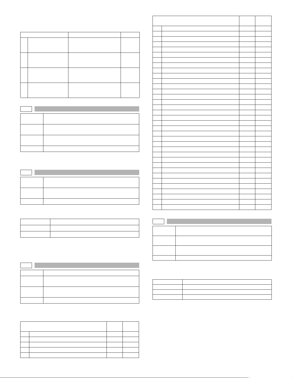
Operation/procedure
1. Select an item with 10-key, and press [START] key.
2. Enter the setting value, and press [START] key.
Item Content Default
1 PR_LIFE_ADJUST
2 TN_LIFE_ADJUST
3 RATE_ADJUST
4 TONER_ADJUST
44-9
Purpose
Function
(Purpose)
Section
Item Operation
Operation/procedure
Used to display the process control correction information.
44-14
Purpose
Function
(Purpose)
Item Operation
Operation/procedure
The following data are displayed.
TH AREA Current environment area
TMP DATA Detection temperature of sensor (C°)
HUD DATA Detection humidity of sensor (%)
* The value before entry of SIM is displayed. (It is not revised in real
time.)
If sim entry is just after power turned on, the display value is all 0.
44-16
Purpose Setting
Function
(Purpose)
Section
Item Operation
Operation/procedure
Sets the toner density control correction value of the traveling distance
count.
1 0 - 93000 (31-sheet model) 1-99 4 5
2 93001 - 186000 (31-sheet model) 1-99 45
3 186001 - 279000 (31-sheet model) 1-99 45
4 279001 - 372000 (31-sheet model) 1-99 45
5 372001 - 465000 (31-sheet model) 1-99 45
Adjustment/Setup/Operation data output/Check
(Display/Print)
Used to display the process control correction
information.
Image process
(Photoconductor/Developing/Transfer/Cleaning)
Adjustment/Setup/Operation data output/Check
(Display/Print)
Used to display the environment (temperature,
humidity) correction information.
Used to set the toner density control correction value.
Image process
(Photoconductor/Developing/Transfer/Cleaning)
DV count correction Disable/
Enable
(0: Disable, 1: Enable)
Life of toner control DV
correction Disable/Enable
(0: Disable, 1: Enable)
Printing rate correction
Disable/Enable
(0: Disable, 1: Enable)
Toner unconditionally supply
correction Disable/Enable
(0: Disable, 1: Enable)
Item
Setting
range
1
1
1
1
Default
Item
6 465001 - 857313 (31-sheet model) 1-99 45
7 857314 - 1714625 (31-sheet model) 1-99 45
8 1714626 - 2571938 (31-sheet model) 1-99 45
9 2571939 - 3429250 (31-sheet model) 1-99 45
10 3429251 - 4286563 (31-sheet model) 1-99 45
11 4286564 - 5143875 (31-sheet model) 1-99 45
12 5143876 - 6001188 (31-sheet model) 1-99 45
13 6001189 - 6858500 (31-sheet model) 1-99 45
14 6858501 - 7715813 (31-sheet model) 1-99 45
15 7715814 - 8573125 (31-sheet model) 1-99 45
16 8573126 - 9430438 (31-sheet model) 1-99 45
17 9430439 - 10287750 (31-sheet model) 1-99 45
18 10287751 - 11145063 (31-sheet model) 1-99 45
19 11145064 - 12002375 (31-sheet model) 1-99 45
20 12002376 - (31-sheet model) 1-99 45
21 0 - 93000 (26-sheet model) 1-99 45
22 93001 - 186000 (26-sheet model) 1-99 45
23 186001 - 279000 (26-sheet model) 1-99 45
24 279001 - 372000 (26-sheet model) 1-99 45
25 372001 - 465000 (26-sheet model) 1-99 45
26 465001 - 857313 (26-sheet model) 1-99 45
27 857314 - 1714625 (26-sheet model) 1-99 45
28 1714626 - 2571938 (26-sheet model) 1-99 45
29 2571939 - 3429250 (26-sheet model) 1-99 45
30 3429251 - 4286563 (26-sheet model) 1-99 45
31 4286564 - 5143875 (26-sheet model) 1-99 45
32 5143876 - 6001188 (26-sheet model) 1-99 45
33 6001189 - 6858500 (26-sheet model) 1-99 45
34 6858501 - 7715813 (26-sheet model) 1-99 45
35 7715814 - 8573125 (26-sheet model) 1-99 45
36 8573126 - 9430438 (26-sheet model) 1-99 45
37 9430439 - 10287750 (26-sheet model) 1-99 45
38 10287751 - 11145063 (26-sheet model) 1-99 45
39 11145064 - 12002375 (26-sheet model) 1-99 45
40 12002376 - (26-sheet model) 1-99 45
44-17
Purpose
Function
(Purpose)
Section
Item Operation
Operation/procedure
The following data are displayed. (The displayed value is the previous
print correction value.)
TARGET Toner concentration control reference value
DEV REF Developer adjustment value
LIFE Toner container life correction value (SIM 44-16)
TH Toner container environment correction value
TARGET = DEV REF+(LIFE-50)+(TH-50)
Developer adjustment value 128, life correction 60 (developer adjustment value plus 10), environment correction 45 (5 subtraction correction), rapid toner supply correction = 128+(60-50)+(45-50) = 133.)
Adjustment/Setup/Operation data output/Check
(Display/Print)
Used to display the toner density control reference
value.
Image process
(Photoconductor/Developing/Transfer/Cleaning)
Setting
range
Default
AR-5726/5731 SIMULATION 6 - 24
Page 53
44-34
Purpose Setting
Function
(Purpose)
Operation/procedure
1. Touch the item to be set.
2. Enter the set value with the 10-key.
To support an individual necessity in paper and the environment, it is
variable in the range of 5 to 30uA in the increment of 1uA in each mode.
When changing +V2, check with +V1 unchanged. If there is any trouble
in the half tone image of graphics, keep the relationship between +V1
and +V2 at the default and change it.
When the image quality is deteriorated because the user selects the
OHP mode and use other than the recommended OHP, decrease the
transfer current to adjust deterioration of black background picture quality. If some of characters are not printed, increase the transfer current.
This setting is changed in linkage with SIM 26-6 destination setting.
*1: SECL/SCA/SEF/EX inch series/EX AB series/EX inch series (FC)/
EX AB series (FC)/China/Taiwan/SEEG2
*2: SEC/SEEG/SUK
1 +V1F (145)
2 +V1R (145)
3 +V2F (145)
4 +V2R (145)
5 +V1S-F (145)
6 +V1S-R (145)
7 +V2S-F (145)
8 +V2S-R (145)
9 +V1SS-F (145)
10 +V1SS-R (145)
11 +V1SS-F (145)
12 +V1SS-R (145)
13 +V1 THICK (145)
14 +V2 THICK (145)
+V1 THICK S
15
(145)
+V2 THICK S
16
(145)
17 +V1 THIN (145)
18 +V2 THIN (145)
19 +V1 THIN S (145)
20 +V2 THIN S (145)
Used to set the transfer current value in each mode.
Item Content
145mm/s normal paper W
+V1 single surface. Duplex
(Front)
145mm/s normal paper W
+V1 Duplex (Back)
145mm/s normal paper W
+V2 single surface. Duplex
(Front)
145mm/s normal paper W
+V2 Duplex (Back)
145mm/s normal paper N1
+V1 single surface. Duplex
(Front)
145mm/s normal paper N1
+V1 Duplex (Back)
145mm/s normal paper N1
+V2 single surface. Duplex
(Front)
145mm/s normal paper N1
+V2 Duplex (Back)
145mm/s normal paper N2
+V1 single surface. Duplex
(Front)
145mm/s normal paper N2
+V1 Duplex (Back)
145mm/s normal paper N2
+V2 single surface. Duplex
(Front)
145mm/s normal paper N2
+V2 Duplex (Back)
145mm/s thick paper > LTR
+V1
145mm/s thick paper > LTR
+V2
145mm/s thick paper t LT R
+V1
145mm/s thick paper t LT R
+V2
145mm/s thin paper > LTR
+V1
145mm/s thin paper > LTR
+V2
145mm/s thin paper t LTR
+V1
145mm/s thin paper t LTR
+V2
Setting
Default
range
*1 *2
5-30 5
5-30 5
5-30 18 20
5-30 14 18
5-30 5
5-30 5
5-30 18
5-30 18
5-30 5
5-30 5
5-30 18
5-30 18
5-30 5
5-30 14
5-30 5
5-30 14
5-30 5
5-30 18
5-30 5
5-30 18
Item Content
21 +V1 LABEL (145)
22 +V2 LABEL (145)
+V1 LABEL S
23
(145)
+V2 LABEL S
24
(145)
25 +V1 OHP (145) 145mm/s OHP > LTR +V1 5-30 5
26 +V2 OHP(145) 145mm/s OHP > LTR +V2 5-30 14
27 +V1 OHP S (145) 145mm/s OHP t LT R + V 1 5- 3 0 5
28 +V2 OHP S (145) 145mm/s OHP t LT R + V 2 5- 3 0 18
+V1 POSTCARD
29
(145)
+V2 POSTCARD
30
(145)
+V1 POSTCARD
31
S (145)
+V2 POSTCARD
32
S (145)
33 +V1F (122)
34 +V1R (122)
35 +V2F (122)
36 +V2R (122)
37 +V1S-F (122)
38 +V1S-R (122)
39 +V2S-F (122)
40 +V2S-R (122)
41 +V1SS-F (122)
42 +V1SS-R (122)
43 +V2SS-F (122)
44 +V2SS-R (122)
45 +V1 THICK (122)
46 +V2 THICK (122)
+V1 THICK S
47
(122)
+V2 THICK S
48
(122)
49 +V1 THIN (122)
50 +V2 THIN (122)
51 +V1 THIN S (122)
52 +V2 THIN S (122)
53 +V1 LABEL (122)
54 +V2 LABEL (122)
145mm/s label paper > LTR
+V1
145mm/s label paper > LTR
+V2
145mm/s label paper t LT R
+V1
145mm/s label paper t LT R
+V2
145mm/s postcard/envelope
> 100mm +V1
145mm/s postcard/envelope
> 100mm +V2
145mm/s postcard/envelope
t 100mm +V1
145mm/s postcard/envelope
t 100mm +V2
122mm/s normal paper W
+V1 single surface. Duplex
(Front)
122mm/s normal paper W
+V1 Duplex (Back)
122mm/s normal paper W
+V2 single surface. Duplex
(Front)
122mm/s normal paper W
+V2 Duplex (Back)
122mm/s normal paper N1
+V1 single surface. Duplex
(Front)
122mm/s normal paper N1
+V1 Duplex (Back)
122mm/s normal paper N1
+V2 single surface. Duplex
(Front)
122mm/s normal paper N1
+V2 Duplex (Back)
122mm/s normal paper N2
+V2 Duplex (Back)
122mm/s normal paper N2
+V1 single surface. Duplex
(Front)
122mm/s normal paper N2
+V1 Duplex (Back)
122mm/s normal paper N2
+V2 single surface. Duplex
(Front)
122mm/s thick paper > LTR
+V1
122mm/s thick paper > LTR
+V2
122mm/s thick paper t LT R
+V1
122mm/s thick paper t LT R
+V2
122mm/s thin paper > LTR
+V1
122mm/s thin paper > LTR
+V2
122mm/s thin paper t LT R
+V1
122mm/s thin paper t LT R
+V2
122mm/s label paper > LTR
+V1
122mm/s label paper > LTR
+V2
Setting
Default
range
*1 *2
5-30 5
5-30 18
5-30 5
5-30 14
5-30 5
5-30 26
5-30 5
5-30 26
5-30 5
5-30 5
5-30 12 14
5-30 12
5-30 5
5-30 5
5-30 14
5-30 14
5-30 5
5-30 5
5-30 14
5-30 14
5-30 5
5-30 10
5-30 5
5-30 12
5-30 5
5-30 12
5-30 5
5-30 12
5-30 5
5-30 12
AR-5726/5731 SIMULATION 6 - 25
Page 54
Item Content
+V1 LABEL S
55
(122)
+V2 LABEL S
56
(122)
57 +V1 OHP (122) 122mm/s OHP > LTR +V1 5-30 5
58 +V2 OHP (122) 122mm/s OHP > LTR +V2 5-30 8
59 +V1 OHP S (122) 122mm/s OHP t LT R +V 1 5-30 5
60 +V2 OHP S (122) 122mm/s OHP t LT R +V 2 5-30 1 2
+V1 POSTCARD
61
(122)
+V2 POSTCARD
62
(122)
+V1 POSTCARD
63
S (122)
+V2 POSTCARD
64
S (122)
44-40
Purpose Setting
Function
(Purpose)
Operation/procedure
Enter the set value with the 10-key, and press the [START] key.
Set the toner supply previous rotation time.
Setting range 1-99 (sec)
Default 4 (sec)
Used to set the time from the start of the main motor
rotation (Ready) to the start of toner supply in previous
rotation after turning on the power.
122mm/s label paper t LTR
+V1
122mm/s label paper t LTR
+V2
122mm/s postcard/envelope
> 100mm +V1
122mm/s postcard/envelope
> 100mm +V2
122mm/s postcard/envelope
t 100mm +V1
122mm/s postcard/envelope
t 100mm +V2
Setting
Default
range
*1 *2
5-30 5
5-30 12
5-30 5
5-30 16
5-30 5
5-30 16
46
46-2
Purpose Adjustment
Function
(Purpose)
Item Picture quality Density
Operation/procedure
1. Touch the item to be adjusted. (Automatic adjustment)
The currently set value is highlighted beside the adjustment item.
2. Press the [START] key.
The display is shifted to the copy menu.
3. Select the paper feed tray and the print density.
Use the 10-key to set the exposure level.
4. Press the [START] key.
Copying is started.
(Exposure mode)
1
AE
TEXT
2
3
TEXT/PHOTO
4
PHOTO
AE(TS)
5
6
TEXT(TS)
7
TEXT/PHOTO(TS)
* Except for AE and AE (TS), only Level 3 can be set.
Note: When this simulation is canceled, the display returns to the initial
menu but the machine is not reset.
Used to set the exposure level in each exposure mode.
Item Content
AE
Character Level 3.0
Character/Photo Level 3.0
Photo Level 3.0
AE (TS)
Character (TS) Level 3.0
Character/Photo (TS) Level 3.0
Setting
range
Default
1-99 50
46-9
Purpose Adjustment
Function
(Purpose)
Item Picture quality Density
Operation/procedure
1. Touch the item to be adjusted.
The adjustment item and the currently set value are highlighted.
2. Press the [START] key.
The display is shifted to the copy menu.
3. Select the paper feed tray and the print density.
Use the 10-key to set the exposure level.
4. Press the [START] key.
Copying is started.
(Exposure mode (Text))
1 1.0 (SHIFT) Character level 1.0 (shift q’ty) 1-99 22
2 1.0 (GAMMA) Character level 1.0 (slant) 1-99 44
3 2.0 (SHIFT) Character level 2.0 (shift q’ty) 1-99 36
4 2.0 (GAMMA) Character level 2.0 (slant) 1-99 47
5 3.0 (SHIFT) Character level 3.0 (shift q’ty) 1-99 50
6 3.0 (GAMMA) Character level 3.0 (slant) 1-99 50
7 4.0 (SHIFT) Character level 4.0 (shift q’ty) 1-99 61
8 4.0 (GAMMA) Character level 4.0 (slant) 1-99 55
9 5.0 (SHIFT) Character level 5.0 (shift q’ty) 1-99 72
10 5.0 (GAMMA) Character level 5.0 (slant) 1-99 60
TS 1.0
11
(SHIFT)
1TS 1.0
12
(GAMMA)
TS 2.0
13
(SHIFT)
TS 2.0
14
(GAMMA)
TS 3.0
15
(SHIFT)
TS 3.0
16
(GAMMA)
TS 4.0
17
(SHIFT)
TS 4.0
18
(GAMMA)
TS 5.0
19
(SHIFT)
TS 5.0
20
(GAMMA)
Note: When this simulation is canceled, the display returns to the initial
menu but the machine is not reset.
46-10
Purpose Adjustment
Function
(Purpose)
Item Picture quality
Operation/procedure
1. Touch the item to be adjusted.
The adjustment item and the currently set value are highlighted.
2. Press the [START] key.
The display is shifted to the copy menu.
3. Select the paper feed tray and the print density.
Use the 10-key to set the exposure level.
4. Press the [START] key.
Copying is started.
Used to adjust the shift amount and the inclination
value for each level (1 to 5) of the exposure mode
(Text).
Item Content
Character (TS) level 1.0
(shift q’ty)
Character (TS) level 1.0
(slant)
Character (TS) level 2.0
(shift q’ty)
Character (TS) level 2.0
(slant)
Character (TS) level 3.0
(shift q’ty)
Character (TS) level 3.0
(slant)
Character (TS) level 4.0
(shift q’ty)
Character (TS) level 4.0
(slant)
Character (TS) level 5.0
(shift q’ty)
Character (TS) level 5.0
(slant)
Used to adjust the shift amount and the inclination
value for each level (1 to 5) of the exposure mode
(Text/Photo).
Setting
range
Default
1-99 22
1-99 44
1-99 36
1-99 47
1-99 50
1-99 50
1-99 61
1-99 55
1-99 72
1-99 60
AR-5726/5731 SIMULATION 6 - 26
Page 55
(Exposure mode (Text/Photo))
Item Content
11.0 (SHIFT)
21.0 (GAMMA)
32.0 (SHIFT)
42.0 (GAMMA)
53.0 (SHIFT)
63.0 (GAMMA)
74.0 (SHIFT)
84.0 (GAMMA)
95.0 (SHIFT)
10 5.0 (GAMMA)
TS 1.0
11
(SHIFT)
TS 1.0
12
(GAMMA)
TS 2.0
13
(SHIFT)
TS 2.0
14
(GAMMA)
TS 3.0
15
(SHIFT)
TS 3.0
16
(GAMMA)
TS 4.0
17
(SHIFT)
TS 4.0
18
(GAMMA)
TS 5.0
19
(SHIFT)
TS 5.0
20
(GAMMA)
Note: When this simulation is canceled, the display returns to the initial
menu but the machine is not reset.
46-11
Purpose Adjustment
Function
(Purpose)
Item Picture quality Density
Operation/procedure
1. Touch the item to be adjusted.
The adjustment item and the currently set value are highlighted.
2. Press the [START] key.
The display is shifted to the copy menu.
3. Select the paper feed tray and the print density.
Use the 10-key to set the exposure level.
4. Press the [START] key.
Copying is started.
Character/Photo level 1.0
(shift q’ty)
Character/Photo level 1.0
(slant)
Character/Photo level 2.0
(shift q’ty)
Character/Photo level 2.0
(slant)
Character/Photo level 3.0
(shift q’ty)
Character/Photo level 3.0
(slant)
Character/Photo level 4.0
(shift q’ty)
Character/Photo level 4.0
(slant)
Character/Photo level 5.0
(shift q’ty)
Character/Photo level 5.0
(slant)
Character/Photo (TS) level 1.0
(shift q’ty)
Character/Photo (TS) level 1.0
(slant)
Character/Photo (TS) level 2.0
(shift q’ty)
Character/Photo (TS) level 2.0
(slant)
Character/Photo (TS) level 3.0
(shift q’ty)
Character/Photo (TS) level 3.0
(slant)
Character/Photo (TS) level 4.0
(shift q’ty)
Character/Photo (TS) level 4.0
(slant)
Character/Photo (TS) level 5.0
(shift q’ty)
Character/Photo (TS) level 5.0
(slant)
Used to adjust the shift amount and the inclination
value for each level (1 to 5) of the exposure mode
(Photo).
Setting
range
Default
1-99 30
1-99 37
1-99 40
1-99 43
1-99 50
1-99 50
1-99 57
1-99 61
1-99 64
1-99 66
1-99 30
1-99 37
1-99 40
1-99 43
1-99 50
1-99 50
1-99 57
1-99 61
1-99 64
1-99 66
(Exposure mode (Photo))
Item Content
1
1.0(SHIFT)
2
1.0(GAMMA)
2.0(SHIFT)
3
2.0(GAMMA)
4
5
3.0(SHIFT)
3.0(GAMMA)
6
4.0(SHIFT)
7
8
4.0(GAMMA)
5.0(SHIFT)
9
5.0(GAMMA)
10
Note: When this simulation is canceled, the display returns to the initial
menu but the machine is not reset.
46-12
Purpose Adjustment
Function
(Purpose)
Section FAX
Item Image quality
Operation/procedure
1. Select “1: COPY START.”
The currently set value is displayed beside the item.
2. Enter the set value of the exposure level with the 10-key, and
press the [#/P] key.
3. Press the [START] key.
Copying is started and the set value is stored.
Normal display NOW PRINTING
Error display
There is no tray selection operation.
The optimum paper tray for the scanned size is selected.
1 COPY START – –
2 FAX EXP.LEVEL 0-99 50
Note: Executable only when the FAX is installed.
46-13
Purpose Adjustment
Function
(Purpose)
Section FAX
Item Image quality
Operation/procedure
The currently set value is highlighted beside the item.
1. Select an item to be adjusted.
2. Enter the set value of the exposure level with the 10-key.
3. Press the [START] key.
Copying is started and the set value is stored.
There is no tray selection operation.
The optimum paper tray for the scanned size is selected.
1 COPY START Copy start – –
2 EXP.LEVEL Exposure level selection
4 MANUAL Normal text MANUAL
Note: Executable only when the FAX is installed.
Item Setting range Default
Normal display NOW PRINTING
Error display
Item Content Setting range Default
Photo level 1.0 (shift q’ty)
Photo level 1.0 (slant) 50
Photo level 2.0 (shift q’ty) 33
Photo level 2.0 (slant) 50
Photo level 3.0 (shift q’ty) 50
Photo level 3.0 (slant) 50
Photo level 4.0 (shift q’ty) 56
Photo level 4.0 (slant) 61
Photo level 5.0 (shift q’ty) 62
Photo level 5.0 (slant) 66
FAX exposure level adjustment
(1 mode automatic adjustment)
DOOR OPEN
JAM
PAPER EMPTY
FAX exposure level adjustment
(Normal mode individual adjustment)
DOOR OPEN
JAM
PAPER EMPTY
Setting
range
1-99
0-99 503 AE Normal text AE
Default
16
AR-5726/5731 SIMULATION 6 - 27
Page 56
46-14
Purpose Adjustment
Function
(Purpose)
Section FAX
Item Image quality
Operation/procedure
1. Select “1: COPY START.”
The currently set value is displayed beside the item.
2. Enter the set value of the exposure level with the 10-key, and
press the [#/P] key.
3. Press the [START] key.
Copying is started and the set value is stored.
Normal display NOW PRINTING
Error display
There is no tray selection operation.
The optimum paper tray for the scanned size is selected.
1 COPY START Copy start – –
2 EXP.LEVEL Exposure level selection
3 AE (PHOTO ON) Fine text AE (Half tone)
4 AE (PHOTO OFF) Fine text AE
MANUAL
5
(PHOTO ON)
MANUAL
6
(PHOTO OFF)
Note: Executable only when the FAX is installed.
FAX exposure level adjustment
(Fine text mode individual adjustment)
DOOR OPEN
JAM
PAPER EMPTY
Item Content
Fine text MANUAL
(Half tone)
Fine text MANUAL
Setting
range
0-99 50
Default
46-16
Purpose Adjustment
Function
(Purpose)
Section FAX
Item Image quality
Operation/procedure
The currently set value is highlighted beside the item.
1. Select an item to be adjusted.
2. Enter the set value of the exposure level with the 10-key.
3. Press the [START] key.
Copying is started and the set value is stored.
Normal display NOW PRINTING
Error display
There is no tray selection operation.
The optimum paper tray for the scanned size is selected.
1 COPY START Copy start – –
2 EXP.LEVEL Exposure level selection
3 AE (PHOTO ON) Ultra Fine AE (Half tone)
4 AE (PHOTO OFF) Ultra Fine AE
MANUAL
5
(PHOTO ON)
MANUAL
6
(PHOTO OFF)
Note: Executable only when the FAX is installed.
FAX exposure level adjustment
(Ultra Fine mode individual adjustment)
DOOR OPEN
JAM
PAPER EMPTY
Item Content
Ultra Fine MANUAL
(Half tone)
Ultra Fine MANUAL
Setting
range
0-99 50
Default
46-15
Purpose Adjustment
Function
(Purpose)
Section FAX
Item Image quality
Operation/procedure
The currently set value is highlighted beside the item.
1. Select an item to be adjusted.
2. Enter the set value of the exposure level with the 10-key.
3. Press the [START] key.
Copying is started and the set value is stored.
Normal display NOW PRINTING
Error display
There is no tray selection operation.
The optimum paper tray for the scanned size is selected.
1 COPY START Copy start – –
2 EXP.LEVEL Exposure level selection
3 AE (PHOTO ON)
4 AE (PHOTO OFF) Super Fine AE
MANUAL
5
(PHOTO ON)
MANUAL
6
(PHOTO OFF)
Note:Executable only when the FAX is installed.
FAX exposure level adjustment
(Super Fine mode individual adjustment)
DOOR OPEN
JAM
PAPER EMPTY
Item Content
Super Fine AE
(Half tone)
Super Fine MANUAL
(Half tone)
Super Fine MANUAL
Setting
range
0-99 50
Default
46-18
Purpose Adjustment
Function
(Purpose)
Item Picture quality
Operation/procedure
1. Touch the item to be adjusted.
The adjustment item and the current set value are highlighted.
2. Press the [START] key.
The display is shifted to the copy menu.
3. Select the paper feed tray and the print density.
Set the exposure level with the 10-key.
4. Press the [START] key.
Copying is started.
(Auto adjustment)
AE
1
TEXT
2
TEXT/PHOTO
3
4
PHOTO
AE(TS)
5
TEXT(TS)
6
7
TEXT/PHOTO(TS)
Note: When this simulation is canceled, the display returns to the initial
menu but the machine is not reset.
Used to adjust inclination for each exposure mode.
Item Content
AE
Character Level 3.0
Character/Photo Level 3.0
Photo Level 3.0
AE(TS)
Character (TS) Level 3.0
Character/Photo
(TS)
Level 3.0
Setting
range
1-99 50
Default
AR-5726/5731 SIMULATION 6 - 28
Page 57
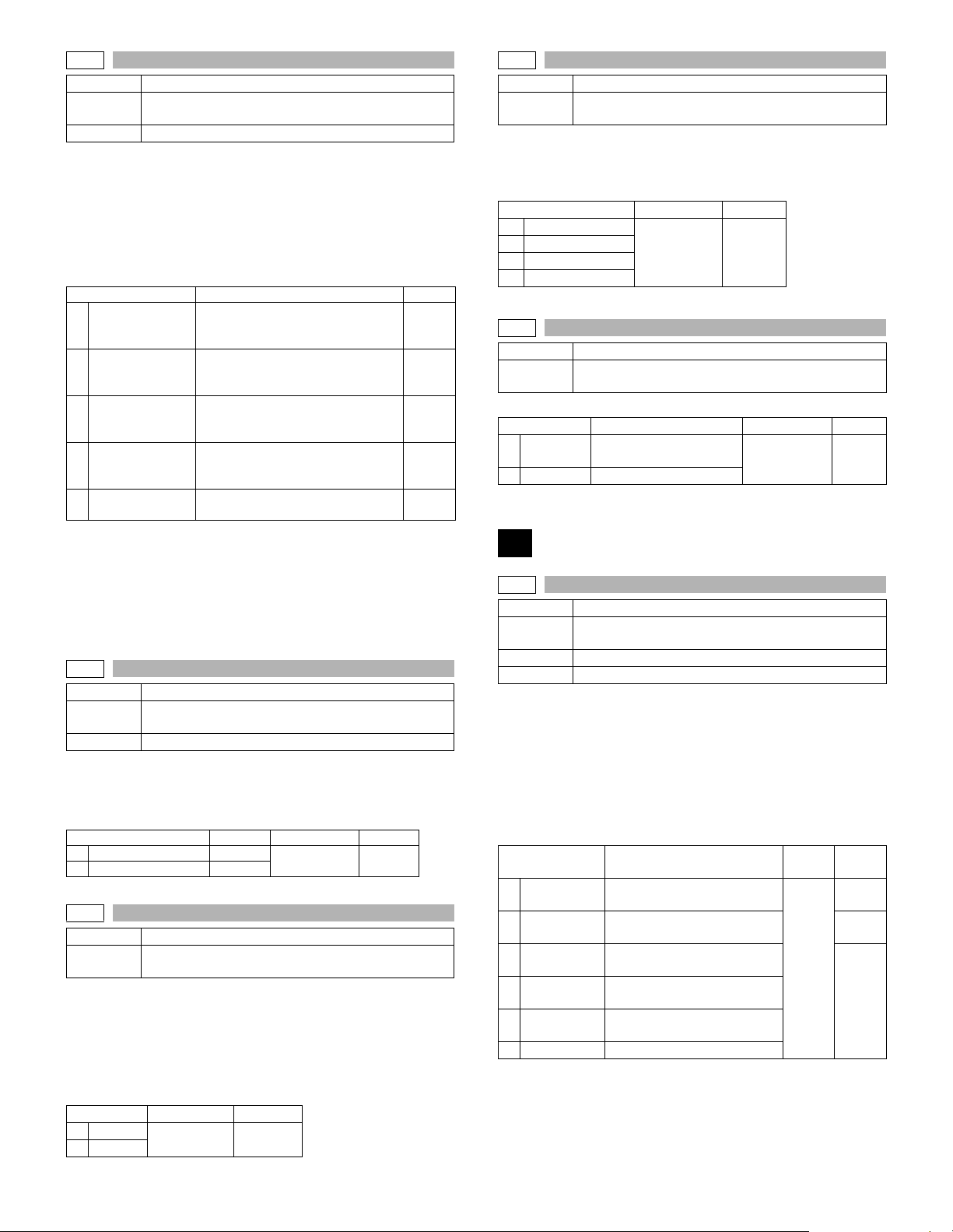
46-19
Purpose Adjustment
Function
(Purpose)
Item Picture quality
Operation/procedure
1. Touch the item to be adjusted.
The currently set value is highlighted beside the adjustment item.
2. Press the [START] key.
The display is shifted to the adjustment value entry menu.
Enter the adjustment value with the 10-key, and press the [START] key.
3.
When the [SYSTEM SETTINGS] key is pressed, the display returns to
the original state (adjustment item selection menu).
AE MODE
1
(1:EXPOSURE
AE STOP(COPY)
(0:FIXED
2
AE MODE(FAX)
(0:FIXED
3
AE STOP(SCAN)
(0:FIXED
4
5
PHOTO MODE
* Auto exposure mode
• When SIM 26-6 (Destination setup) is changed from EX Japan to
Japan, the setup value becomes 1 (Default: Japan). If, on the contrary, it is changed from Japan to EX Japan, the set value becomes
2 (Default: EX Japan)
• If the auto exposure mode setup value is changed, the setup value
of SIM 46-30 (AE limit setup) is reset to the default value.
46-20
Purpose Adjustment
Function
(Purpose)
Item Picture quality
Operation/procedure
1. Touch the item to be adjusted.
The adjustment item and the currently set value are highlighted.
2. Enter the set value with the 10-key.
1
SPF EXPOSURE
RSPF EXPOSURE
2
46-30
Purpose Setting
Function
(Purpose)
Operation/procedure
1. Touch the item to be adjusted.
The adjustment item and the currently set value are highlighted.
2. Enter the set value with the 10-key.
If SIM 26-6 (Destination setup) and SIM46-19 (Auto exposure mode)
are changed, this setup is also changed to the default value accordingly.
Item Setting range Default
1AE
2 AE(TS)
Used to set the control method of the exposure mode.
Item Content Default
2:TONER)
1:REAL TIME)
1:REAL TIME)
1:REAL TIME)
Used to set the exposure correction value of SPF/
RSPF for OC exposure.
Item Content Setting range Default
Used to set the AE and the limit value in AE
(Toner save).
Auto exposure mode*
(1: Priority on Image quality,
2: Priority on toner consumption)
Auto exposure STOP mode
(COPY)
(0: Fixed, 1: Real-time)
Auto exposure STOP mode (FAX)
(0: Fixed, 1: Real-time)
Auto exposure STOP mode
(SCANNER)
(0: Fixed, 1: Real-time)
Photo mode
(1: ED (Error diffusion) , 2: DT (Dither))
SPF
RSPF
0-31 0
1-99 53
2
0
0
0
2
46-31
Purpose Setting
Function
(Purpose)
Operation/procedure
1. Touch the item to be adjusted.
The adjustment item and the currently set value are highlighted.
2. Enter the set value with the 10-key.
1AE
2 TEXT
3 TEXT/PHOTO
4PHOTO
46-39
Purpose Setting
Function
(Purpose)
Enter the set value with the 10-key.
0HAIRLINE
1 PRINTER Printed original
Used to set the AE and the limit value in AE
(Toner save).
Item Setting range Default
0-2 1
Used to switch the FAX send image quality.
Item Content Setting range Default
Original with pencil lines
and thin lines
0-1 0
48
48-1
Purpose Adjustment
Function
(Purpose)
Section Image processing
Item Picture quality
Operation/procedure
1. Touch the item to be set.
The item and the currently set value are highlighted.
2. Press the [START] key.
The display is shifted to the copy menu.
3. Select the paper feed tray and the print density, and enter the
adjustment value with the 10-key.
4. Press the [START] key.
Copying is started.
1F-R
2SCAN
3 SPF (SIDE1)
4 SPF (SIDE2)
5 DUPLEX
6 MirSpeed Mirror speed adjustment
Note: When this simulation is canceled, the display is shifted to the ini-
tial menu, but the machine is not reset.
Used to adjust the copy mode magnification ratio
(main scanning direction, sub scanning direction).
Item Content
Main scanning magnification
ratio adjustment
Sub scanning magnification
ratio adjustment
RSPF surface sub scan
magnification ratio
RSPF back surface sub scan
magnification ratio
DUPLEX sub scanning
magnification ratio adjustment
Setting
range
1-99
Default
50
60
50
AR-5726/5731 SIMULATION 6 - 29
Page 58
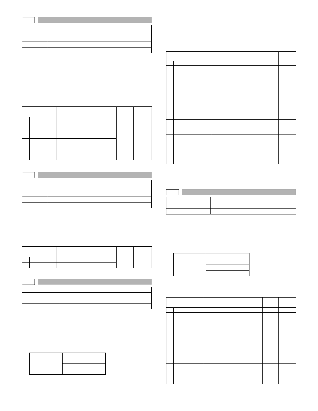
48-2
Purpose Adjustment
Function
(Purpose)
Section Image processing
Item Picture quality
Operation/procedure
1. Touch the item to be set.
The item and the currently set value are highlighted.
2. Press the [START] key.
The display is shifted to the copy menu.
3. Select the paper feed tray and the print density, and enter the
adjustment value with the 10-key.
4. Press the [START] key.
Copying is started.
1
F-R
SCAN
2
SPF (SIDE1)
3
4
SPF (SIDE2)
48-3
Purpose Adjustment
Function
(Purpose)
Section Image processing
Item Picture quality
Operation/procedure
1. The adjustment item and the currently set value are highlighted.
2. Enter the adjustment value with the 10-key.
Changes magnification ratio by changing speed of main motor.
The change of the paper transfer speed is 0.1% when changing value
is 1.
1
145mm/s
122mm/s
2
48-8
Purpose Adjustment
Function
(Purpose)
Section FA X
Operation/procedure
The currently set value is highlighted beside the item.
1. Select an item to be adjusted.
2. Enter the set value of the magnification ratio adjustment with the
10 key.
3. Press the [START] key.
Copying is started and the set value is stored.
Normal display NOW PRINTING
Error display
Used to adjust the scanner mode magnification ratio
(main/sub scanning direction).
Item Content
Main scanning magnification
ratio adjustment
Sub scanning magnification
ratio adjustment
RSPF surface sub scan
magnification ratio
RSPF back surface sub scan
magnification ratio
Used to adjust the print mode magnification ratio
correction.
Item Content
Main motor speed (145mm/s)
Main motor speed (122mm/s)
FAX magnification adjustment (read)
DOOR OPEN
JAM
PAPER EMPTY
Setting
range
Setting
range
45-55 50
Default
1-99 50
Default
There is no operation of tray selection.
The optimum paper tray for the scanned size is selected.
Even when the SPF/RSPF is selected, if there is no original on the
SPF/RSPF, the OC is scanned.
Even when the OC is selected, if there is any original on the SPF/
RSPF, the SPF/RSPF is scanned. (Setting 2)
Item Content
1 COPY START Copy start – –
SCAN SELECT
2
(OC/SPF/RSPF)
3OC(MAIN)
4OC(SUB)
5 SPF(MAIN)
6SPF(SUB)
7 RSPF(MAIN)
8 RSPF(SUB)
* The adjustment can be made in the range of –12.7% - +12.7% by
the increment of 0.1%.
Note: Executable only when the FAX is installed.
48-9
Purpose Adjustment
Function (Purpose) FAX magnification adjustment (print)
Section FA X
Operation/procedure
The currently set value is highlighted beside the item.
1. Select an item to be adjusted.
2. Enter the set value of the magnification ratio correction with the 10
key.
3. Press the [START] key.
Normal display NOW PRINTING
Error display
There is no operation of tray selection.
The optimum paper tray for the scanned size is selected.
When two pages are scanned, duplex printing is made.
Item Content
1 COPY START Copy start 1-255 128
2 Horizontal
3 Vertical
Horizontal
4
(DUPLEX)
Ver tic al
5
(DUPLEX)
Note: Executable only when the FAX is installed.
Scan selection
(OC/ SPF/RSPF)
SCAN Main scanning
magnification ratio
adjustment (OC)
SCAN Sub scanning
magnification ratio
adjustment (OC)
SCAN Main scanning
magnification ratio
adjustment (SPF)
SCAN Sub scanning
magnification ratio
adjustment (SPF)
SCAN Main scanning
magnification ratio
adjustment (RSPF)
SCAN Sub scanning
magnification ratio
adjustment (RSPF)
DOOR OPEN
JAM
PAPER EMPTY
Print magnification ratio
adjustment (Horizontal, vertical
to paper passing)
Print magnification ratio
adjustment (Vertical, parallel to
paper passing)
Print magnification ratio
adjustment on the back surface
(Horizontal, vertical to paper
passing)
Print magnification ratio
adjustment on the back surface
(Vertical, parallel to paper
passing)
Setting
range
1-255* 128
1-255* 128
1-255* 128
1-255* 128
1-255* 128
1-255* 128
1-255* 128
Setting
range
1-255 128
1-255 128
1-255 128
1-255 128
Default
Default
AR-5726/5731 SIMULATION 6 - 30
Page 59
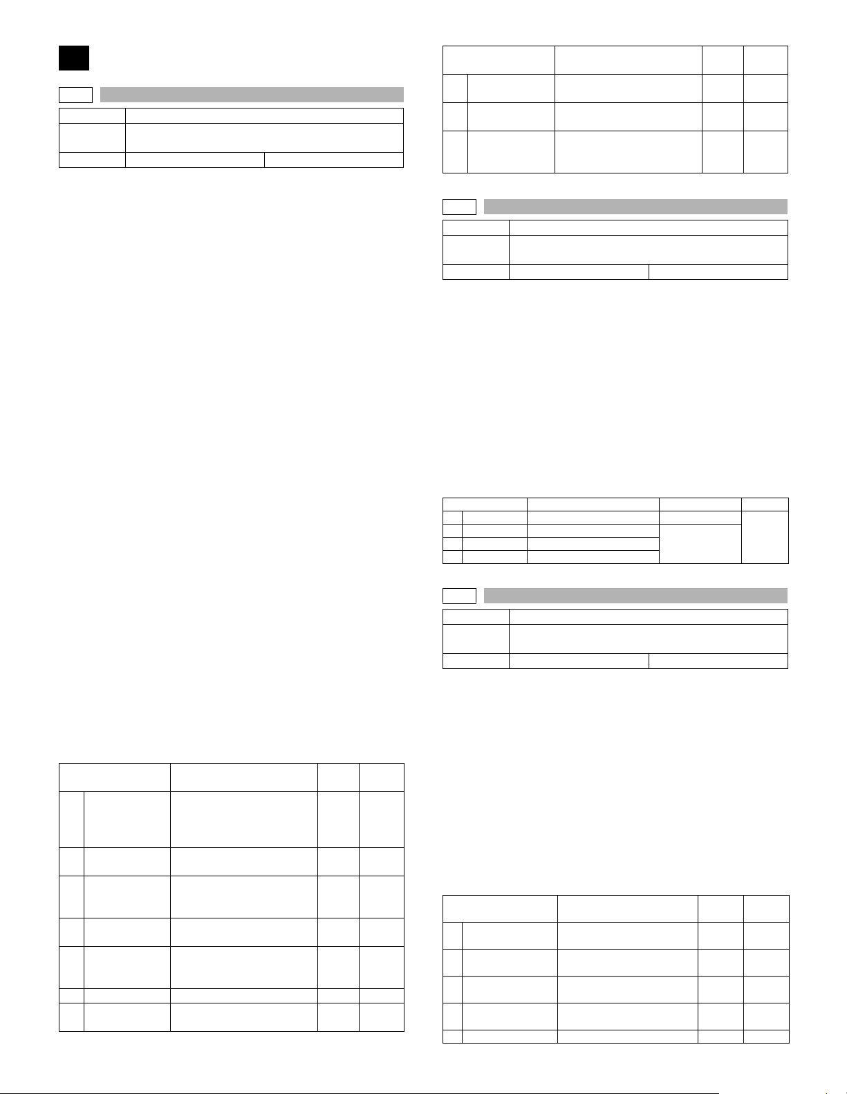
50
50-1
Purpose Adjustment
Function
(Purpose)
Item Picture quality Image position
Operation/procedure
1. Touch the item to be adjusted.
The item and the currently set value are highlighted.
2. Enter the adjustment value with the 10-key and press the [P] key.,
The display goes to the copy menu.
When the [START] key is pressed, the display goes to the copying
state and print is started.
(When the [P] key is pressed: Copy menu)
3. Select the paper feed tray and the print density.
Enter the exposure level with the 10-key.
4. Press the [START] key.
Copying is started.
Note: When this simulation is canceled, the display is shifted to the ini-
tial menu, but the machine is not reset.
(Adjustment procedure)
1. Note down the adjustment value of SIM 50-5 (Items 1, 2, 3, 4), and
change the value to 99.
2. Set SIM 50-1 (Items 2, 3, 4, 5) to 1. (By setting to 1, there is no void.)
3. Place a chart with a clear lead edge (or a ruler) on the OC document table.
4. Use SIM 50-1 (Item 1) to execute test print. Check the print out and
adjust so that the lead edge image is printed. (1 - 99: About
0.127mm/Step)
5. Reset the adjustment values of SIM 50-5 (Items 1, 2, 3, 4) to the
original values, and execute test print. Check the print out and
adjust so that the lead edge image is printed on the lead edge of
paper. (1 - 99: About 0.127mm/Step).
6. Adjust SIM 50-1 (Items 2, 3, 4, 5) so that the lead edge void on the
print out is the specified value. (1 - 99: About 0.127mm/Step)
7. Similar to procedure 6, adjust SIM 50-1 (Item 6, 7) so that the rear
edge void is the specified value. (1 - 99: About 0.127mm/Step)
8. Similar to procedure 6, adjust SIM 50-1 (Item 8, 9) so that the left
edge void is the specified value. (1 - 99: About 0.127mm/Step)
9. Make an enlargement copy (400%), and check that there is no
shade of the cabinet printed at the lead edge.
10. If there is a shade printed at the lead edge in procedure 9, adjust
SIM 50-1 (Item 10). (1 - 5: About 0.677mm)
* If there is no problem, set to 2.
1
RRC-A
DEN-A
2
DEN-A-MANUAL
3
DEN-A -OPTION
4
DEN-A -DUPLEX
5
DEN-B
6
7
DEN-B-DUP
Used to adjust the copy lead edge position.
Item Content
Original scan start position
adjustment
Lead edge position
adjustment value (OC)
Lead edge cancel
adjustment (Main tray)
Lead edge cancel
adjustment (Manual feed
tray)
Lead edge cancel
adjustment (Option tray)
Lead edge cancel
adjustment (back of the
machine)
Rear edge void adjustment 1-99 30
Rear edge void adjustment
(Duplex)
Setting
Default
range
1-99 43
1-99 18
1-99 18
1-99 18
1-99 18
1-99 50
Item Content
8
SIDE VOID
9
SIDE VOID-DUP
10
LOSS(OC)
50-5
Purpose Adjustment
Function
(Purpose)
Item Picture quality Print area
Operation/procedure
1. Touch the item to be adjusted.
The item and the currently set value are highlighted.
2. Enter the adjustment value with the 10-key and press the [P] key.,
The display goes to the copy menu.
When the [START] key is pressed, the display goes to the copying
state and print is started.
(When the [P] key is pressed: Copy menu)
3. Select the paper feed tray and the print density.
Enter the exposure level with the 10-key.
4. Press the [START] key.
Copying is started.
Note: When this simulation is canceled, the display is shifted to the ini-
tial menu, but the machine is not reset.
1TRAY1
2OPTION
3MANUAL
4DUPLEX
50-6
Purpose Adjustment
Function
(Purpose)
Item Picture quality Image position
Operation/procedure
1. Touch the item to be adjusted.
The item and the currently set value are highlighted.
2. Enter the adjustment value with the 10-key and press the [P] key.,
The display goes to the copy menu.
When the [START] key is pressed, the display goes to the copying
state and print is started.
(When the [P] key is pressed: Copy menu)
3. Select the paper feed tray and the print density.
Enter the exposure level with the 10-key.
4. Press the [START] key.
Copying is started.
Note: When this simulation is canceled, the display is shifted to the ini-
tial menu, but the machine is not reset.
1
SIDE1
SIDE2
2
3
END EDGE
LOSS(SIDE1)
4
5
LOSS(SIDE2) Back image loss quantity set
Used to adjust the print image position (top margin) on
the print paper in the print mode.
Item Content Setting range Default
Used to adjust the print image position (top margin) on
print paper in the copy mode. (RSPF)
Item Content
Left edge void adjustment
(First print surface)
Left edge void adjustment
(Duplex)
Image loss amount
adjustment (Lead edge
image loss set value) (OC)
1st tray 0-99
Option tray
Manual feed
Back print
Surface original scan start
position adjustment
Back original scan start
position set
Rear edge void adjustment
(RSPF)
Surface image loss quantity
set
Setting
range
1-99 18
1-99 18
1-5 3
1-99
Setting
range
1-99 50
1-99 50
1-99 50
1-5 3
1-5 3
Default
53
Default
AR-5726/5731 SIMULATION 6 - 31
Page 60
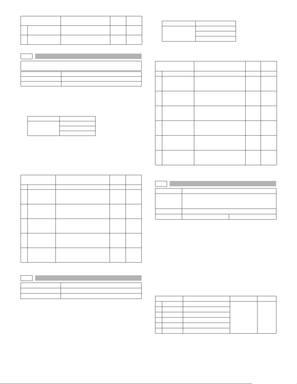
Item Content
REARLOS(SIDE1)
6
REARLOS(SIDE2)
7
50-8
The adjustments on the machine side must have been normally
completed.
Purpose Adjustment
Function (Purpose) FAX lead edge adjustment (read)
Section FAX
The currently set value is highlighted beside the item.
1. Select an item to be adjusted.
2. Enter the set value of the lead edge adjustment with the 10 key.
3. Press the [START] key.
Copying is started.
Normal display NOW PRINTING
Error display
There is no tray selection operation.
The optimum paper tray for the scanned size is selected.
4. Select the scanning method.
Even when the SPF/RSPF is selected, if there is no original on the
SPF/RSPF, the OC is scanned.
Even when the OC is selected, if there is any original on the SPF/
RSPF, the SPF/RSPF is scanned. (Setting 2)
Item Content
1 COPY START Copy start – –
SCAN
2
SELECT (OC/
SPF/RSPF)
3LEAD
4 LEFT
5REAR
6RIGHT
Note: Executable only when the FAX is installed.
50-9
Purpose Adjustment
Function (Purpose) FAX lead edge adjustment (print)
Section FAX
Operation/procedure
The currently set value is highlighted beside the item.
1. Select an item to be adjusted.
2. Enter the set value of the lead edge adjustment with the 10 key.
Surface rear edge image
loss quantity set
Back rear edge image loss
quantity set
DOOR OPEN
JAM
PAPER EMPTY
Scan selection (1: OC,
2: SPF, 3: RSPF back)
Scan lead edge position
adjustment value of the
selected method in 2.
Scan left edge position
adjustment value of the
selected method in 2.
Scan rear edge position
adjustment value of the
selected method in 2.
Scan right edge position
adjustment value of the
selected method in 2.
Setting
range
Setting
range
43-57 50
43-57 50
43-57 50
43-57 50
Default
1-5 3
1-5 3
Default
1-3 1
3. Press the [START] key.
Normal display NOW PRINTING
DOOR OPEN
Error display
There is no tray selection operation.
The optimum paper tray for the scanned size is selected.
When two pages are scanned, duplex print is made,
Item Content
1 COPY START Copy start – –
2LEAD
3LEFT
4REAR
LEAD
5
(DUPLEX)
6 LEFT (DUPLEX)
REAR
7
(DUPLEX)
Note: Executable only when the FAX is installed.
50-10
Purpose Adjustment
Function
(Purpose)
Section Image processing (ICU)
Item Picture quality Image position
Operation/procedure
1. Touch the item to be adjusted.
The item and the currently set value are highlighted.
2. Enter the adjustment value with the 10-key and press the [P] key.,
The display goes to the copy menu.
When the [START] key is pressed, the display goes to the copying
state and print is started.
(When the [P] key is pressed: Copy menu)
3. Select the paper feed tray and the print density.
Enter the exposure level with the 10-key.
4. Press the [START] key.
Copying is started.
Note: When this simulation is canceled, the display is shifted to the ini-
tial menu, but the machine is not reset.
Item Content Setting range Default
1
BYPASS
2
TRAY1
TRAY2
3
4
TRAY3
5
TRAY4
DUPLEX
6
JAM
PAPER EMPTY
Setting
range
Print lead edge void
adjustment value
(Front surface)
Print left edge void
adjustment value
(Front surface)
Print rear edge void
adjustment value
(Front surface)
Print lead edge void
adjustment value
(Back surface)
Print left edge void
adjustment value
(Back surface)
Print rear edge void
adjustment value
(Back surface)
Used to adjust the print image center position.
(Adjustment can be made for each paper feed
section.)
Manual paper feed
1st tray
2nd tray
3rd tray
4th tray
Back print
43-57 53
43-57 53
43-57 53
43-57 53
43-57 53
43-57 53
1-99 50
Default
AR-5726/5731 SIMULATION 6 - 32
Page 61
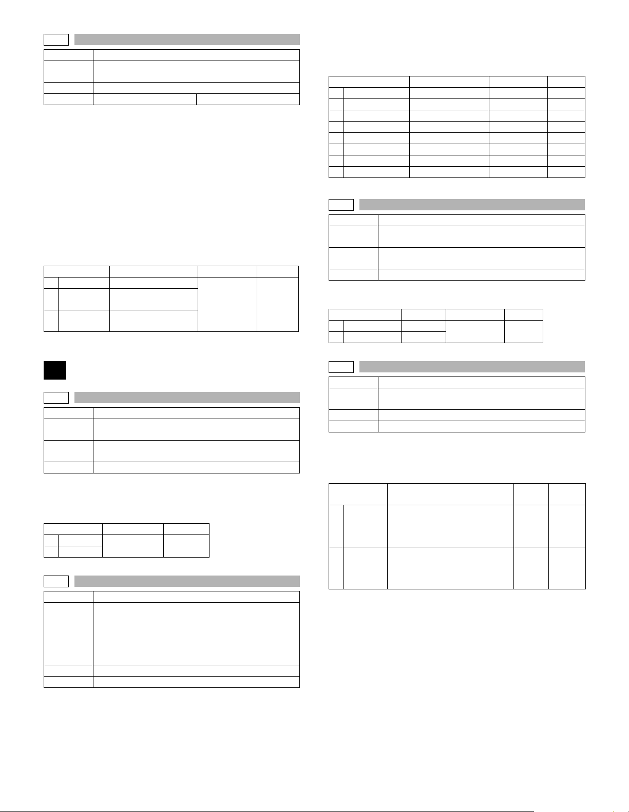
50-12
Purpose Adjustment
Function
(Purpose)
Section Image processing
Item Picture quality Image position
Operation/procedure
1. Touch the item to be adjusted.
The item and the currently set value are highlighted.
2. Enter the adjustment value with the 10-key and press the [P] key.,
The display goes to the copy menu.
When the [START] key is pressed, the display goes to the copying
state and print is started.
(When the [P] key is pressed: Copy menu)
3. Select the paper feed tray and the print density.
Enter the exposure level with the 10-key.
4. Press the [START] key.
Copying is started.
Note: When this simulation is canceled, the display is shifted to the ini-
tial menu, but the machine is not reset.
1
OC
2
SPF(SIDE1)
SPF(SIDE2)
3
Used to adjust the print image center position.
(Adjustment can be made for each document mode.)
Item Content Setting range Default
OC document scan
RSPF document front
surface scan
RSPF document back
surface scan
1-99 50
4. Press the [START] key.
Copying is started.
Note: When this simulation is canceled, the display is shifted to the ini-
tial menu, but the machine is not reset.
Item Content Setting range Default
1 BYPASS
2TRAY1
3TRAY2
4TRAY3
5TRAY4
6DUPLEX
7 SPF(SIDE1)
8 SPF(SIDE2)
51-8
Purpose Setting
Function
(Purpose)
Section
Item Operation
Operation/procedure
Select the set value with the 10-key.
Item Content Setting range Default
0
ON
OFF
1
Manual feed 1-99 50
1st tray 1-99 50
2nd tray 1-99 50
3rd tray 1-99 50
4th tray 1-99 50
Back print 1-99 70
RSPF front surface 1-99 50
RSPF back surface 1-99 50
Used to set the OPC drum separation pawl operation
inhibit. (ON/OFF)
Image process
(Photoconductor/Developing/Transfer/Cleaning)
Enable
Disable
0-1 0
51
51-1
Purpose Adjustment
Function
(Purpose)
Section
Item Operation
Operation/procedure
1. Touch the item to be adjusted.
The item and the currently set value are highlighted.
2. Enter the adjustment value with the 10-key.
Item Setting range Default
1
145mm/s
122mm/s
2
51-2
Purpose Adjustment
Function
(Purpose)
Section Paper transport (Discharge/Switchback/Transport)
Item Operation
Operation/procedure
1. Touch the item to be adjusted.
The item and the currently set value are highlighted.
2. Press the [START] key.
The display is shifted to the copy menu.
3. Select the paper feed tray and the print density.
Enter the adjustment value with the 10-key.
Used to adjust the OPC drum separation pawl ON time.
Image process
(Photoconductor/Developing/Transfer/Cleaning)
1-99 50
Used to adjust the contact pressure of paper onto the
resist roller in each section (copier paper feed section,
duplex paper feed section, RSPF paper feed section).
(When the print image position varies greatly for the
paper or when a lot of paper jam troubles occur, the
adjustment is required.)
51-9
Purpose Setting
Function
(Purpose)
Section Process (OPC drum, developing, transfer, cleaning)
Item Operation
Operation/Procedure
1. Touch the item to be adjusted.
The item and the currently set value are highlighted.
2. Enter the set value with the 10-key.
Item Content
1SHV ON
2SHV OFF
Used to adjust the OPC drum separation voltage ON/
OFF timing.
Setting
range
Separation voltage ON timing
* Transfer V2ON reference
(Synchronized with the
adjustment value of 50.)
Separation voltage OFF timing
* Transfer V2OFF reference
(Synchronized with the
adjustment value of 50.)
25-90 50
50-90 75
Default
AR-5726/5731 SIMULATION 6 - 33
Page 62
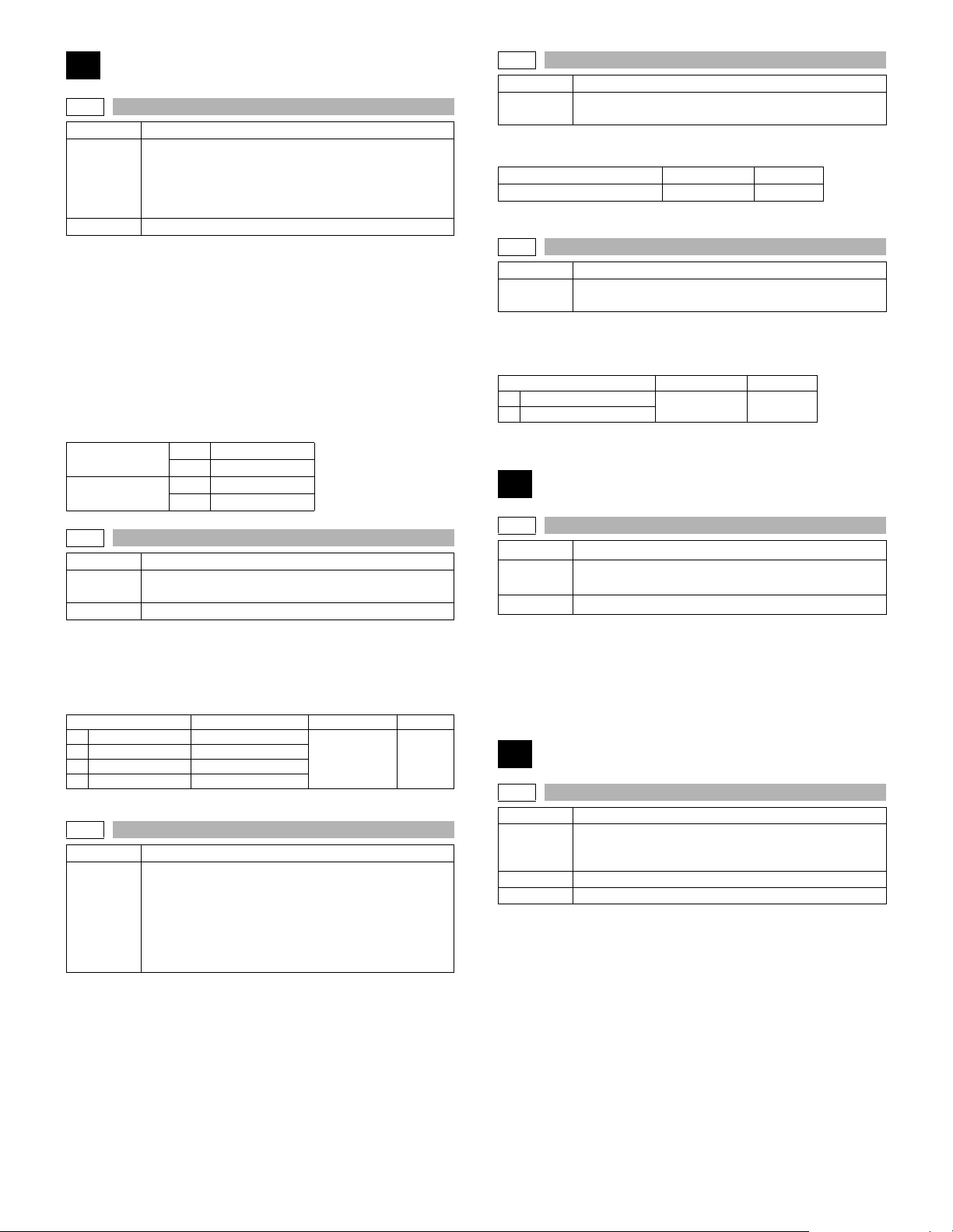
53
53-6
Purpose Adjustment
Used to adjust the detection level of the RSPF width.
Function
(Purpose)
Section RSPF
Operation/Procedure
(Max. position setting)
1. Set the guide to the maximum position, and press the [START] key.
2. Set A4R and fit the guide, and press the [START] key.
3. Set A5R and fit the guide, and press the [START] key.
4. Set the guide to the minimum position, and press the [START] key.
5. Set the paper recognition width (+), and press the [START] key.
6. Set the paper recognition width (–),and press the [START] key.
If “FAILED” is displayed in the above procedure 1, 2, 3, or 4, repeat the
adjustment.
(Middle position L/S setting)
Middle position
adjustment L
Middle position
adjustment S
53-7
Purpose Adjustment
Function
(Purpose)
Section RSPF
Operation/Procedure
1. Touch the item to be adjusted.
The item and the currently set value are highlighted.
2. Enter the RSPF original tray size adjustment value (specified on
the back of the RSPF) with the 10-key.
1 MAX POSITION Max. width
2 POSITION 1 Adjustment point 1
3 POSITION 2 Adjustment point 2
4 MIN POSITION Min. width
53-8
Purpose Adjustment
Function
(Purpose)
Operation/Procedure
With the RSPF or the OC cover open, put a white paper on the OC
glass (the RSPF glass surface is included for the RSPF standard
model), and press the [START] key.
If the adjustment is executed normally, the adjustment value is displayed and saved in the EEPROM. If an error occurs, “ERR” is displayed and the value is not saved in the EEPROM.
If the adjustment is not performed because of abnormality, “---” is displayed.
During execution of the adjustment, the operation cannot be interrupted.
The adjustment method is the 4-point system. Set the
guide to Max. (A3/WLetter) position, A4R/Letter R
position, A5R/Invoice R position, and Min. position for
adjustment.
YES MID-L ADJ.ON
NO MID-L ADJ.OFF
YES MID-S ADJ.ON
NO MID-S ADJ.OFF
Used to enter the RSPF width detection adjustment
value.
Item Content Setting range Default
0-999 0
Used to adjust the RSPF scan position of the mirror
unit automatically. For the RSPF scan position
automatic adjustment, the mirror unit is shifted to
11mm before the RSPF glass cover edge, and is
operated automatically to scan images by the unit of 1
step, detecting the position up to the glass cover
automatically.
53-9
Purpose Adjustment
Function
(Purpose)
Operation/Procedure
Press [START] key.
Read position adjustment 1-99 50
53-10
Purpose Adjustment
Function
(Purpose)
Operation/Procedure
1. Press [START] key.
2. Enter the adjustment value with the 10-key.
1 SPF EXPOSURE
2 RSPF EXPOSURE
RSPF read position adjustment
Item Setting range Default
RSPF exp adjustment
Item Setting range Default
1-99 53
55
55-1
Purpose Setting
Function
(Purpose)
Section Operation
Operation/Procedure
Used to enter the number of SW to be changed.
The bit to be changed is specified by 10-key. (The current value is
highlighted.)
When [START] key is pressed, the entered value is set.
Used to set the soft switch.
61
61-1
Purpose Operation test/check
Function
(Purpose)
Section LSU
Item Operation
Operation/procedure
Press the [START] key, and the LSU test is performed.
Used to set the LSU to ON state and check that the sync signal
(HSYNC/) is outputted or not.
After operation for 30 sec, the result is displayed. (Interruption cannot
be made for 5 sec after starting the operation.)
Used to check the LSU (polygon motor) operation.
Check speed can select 145mm/s or 122mm/s
individually.
AR-5726/5731 SIMULATION 6 - 34
Page 63
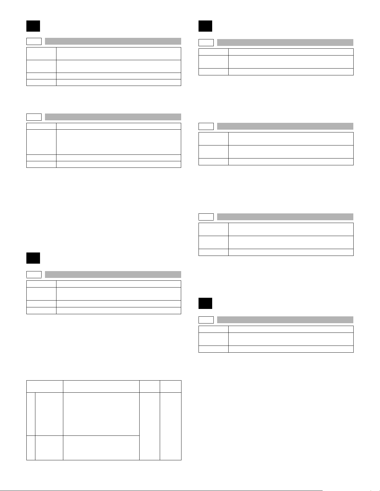
63
65
63-1
Purpose
Function
(Purpose)
Section Scanner (Exposure)
Item Operation
Operation/procedure
Pressing the [START] key performs shading, and displays the result
(center pixel).
63-7
Purpose Adjustment
Function
(Purpose)
Section Scanner
Item Operation
Operation/procedure
Lift the RSPF unit to the fully open position, and press the [START] key.
[ ] indicates the order number of the pixel of the white sheet for RSPF
exposure correction in the RSPF position.
If the adjustment is normally completed, “COMPLETE” is displayed
and data are written into the EEPROM.
In case of an abnormality, “ERROR” is displayed and no data is written
into the EEPROM.
The RSPF white correction start pixel = Displayed pixel position – 34
If the simulation is executed with the RSPF unit closed, an error will
result.
Adjustment/setting/operation data output/check
(display/print)
Used to check the result of shading correction.
(The shading correction data are displayed.)
Used to adjust the RSPF white correction start pixel
position automatically.
This adjustment is performed after the lens unit is
replaced.
64
64-1
Purpose Operation test/check
Function
(Purpose)
Section Printer
Item Operation
Operation/procedure
1. Select the print item with the 10-key.
2. Press the [START] key.
The display is shifted to the copy menu.
3. Select the paper feed tray and the print density.
4. Press the [START] key.
Copying is started.
During execution of the print test, the [SYSTEM SETTINGS] key and
the [INTERRUPTION] key are invalid.
2 BY 4
1
MODE
LATTICE
2
PRINT
* If the IMC board is not installed, the key inputs cannot be made.
Used to check the operation of the printer function
(auto print operation).
Item Content
Self print is made in 2 by 4 mode
(printing 2 lines and not printing
4 lines). Since scanning is not
performed, when the original is
set on the RSPF, this cannot be
performed.
* Duplex print cannot be made.
Lattice print (1cm, 1dot width
WLT, A3 print (A3 main scan,
WLT sub scan)) is performed.
* Duplex print can be made.
Setting
range
1-2 1
Default
65-1
Purpose Adjustment
Function
(Purpose)
Section Operation (Display, Operation)
Operation/Procedure
Press the keys displayed on the LCD sequentially.
Adjust the touch panel coordinates.
When the point of “+” on the LCD is pressed, it turns gray. Press all the
four points of “+.”
65-2
Purpose
Function
(Purpose)
Section Operation (Display, Operation)
Operation/Procedure
Check the touch panel coordinates.
Press the keys displayed on the LCD sequentially.
When the touch panel is pressed, the X-coordinate and the Y-coordinate (dot conversion values) are displayed.
65-5
Purpose
Function
(Purpose)
Section Operation (screen/operation)
Operation/procedure
Check the key input of the operation panel.
Press the keys displayed on the LCD sequentially.
After completion of all key entries, “COMPLETE” is displayed.
Used to adjust the touch panel (LCD display section)
detection position.
Adjustment/Setting/Operation data output check
(Display, Print)
Used to check the touch panel (LCD display section)
detection position adjustment result.
Adjustment/Setting/Operation data output check
(Display, Print)
Used to check the key inputs of the operation panel.
66
66-1
Purpose Setting
Function
(Purpose)
Section FA X
Operation/procedure
1. Enter the soft SW number to be selected with the 10-key.
2. Check and change the setting content of the selected soft SW.
3. Press the [START] key to save the set content.
The FAX-related soft SW is displayed on the LCD, and changing can
be made by monitoring it.
Note: Executable only when the FAX is installed.
Used to change and check the FAX-related soft SW.
AR-5726/5731 SIMULATION 6 - 35
Page 64
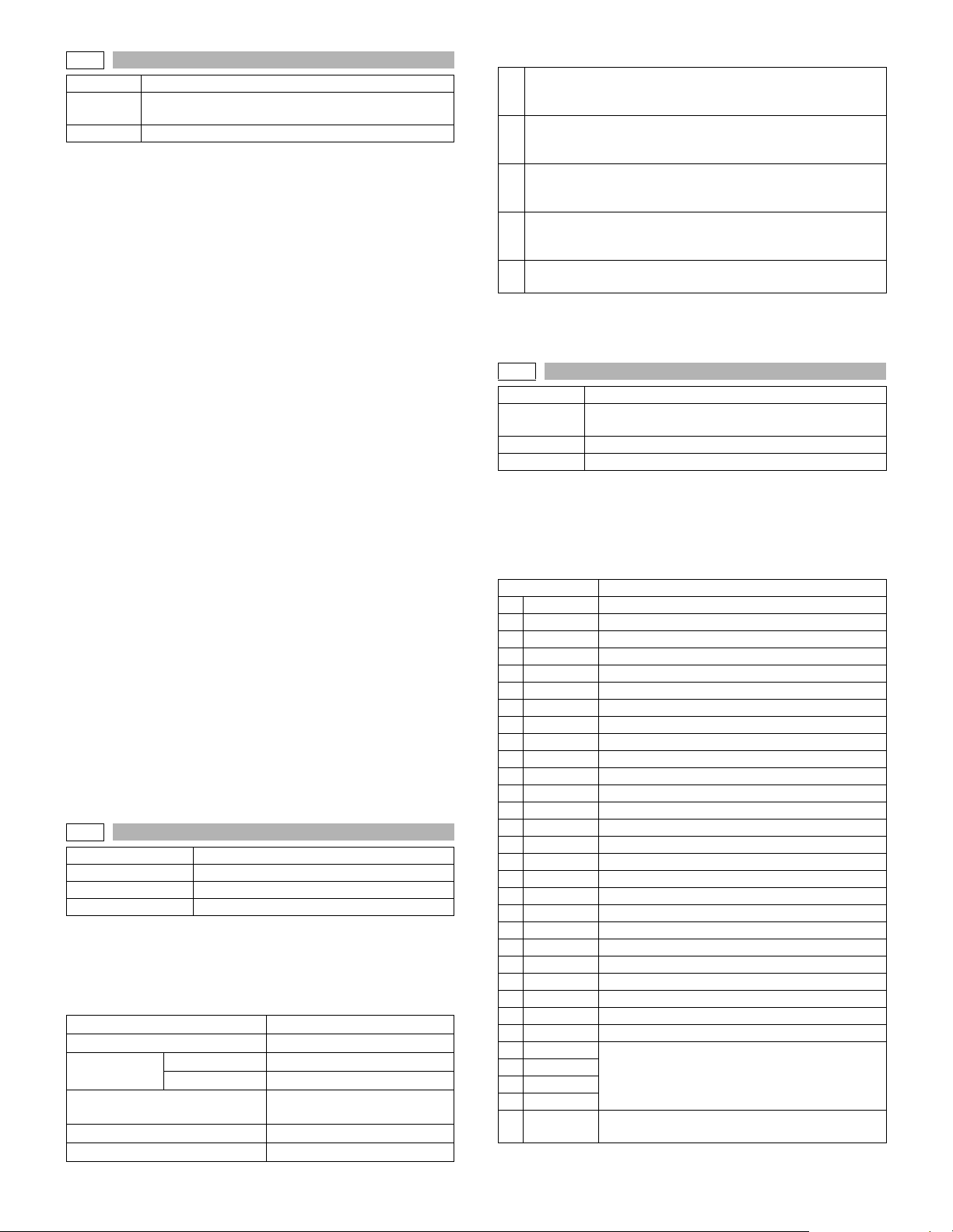
66-2
Purpose Adjustment
Function
(Purpose)
Section FAX
Operation/procedure
1. Enter the country code with the 10-key, and press the [START]
key.
2. When “1: (YES)” is selected, the soft SW corresponding to the
country code is cleared. When “2: (NO)” is selected, the simulation
is canceled.
Country code
Japan : 00000000
U.S.A. : 10110101
Australia : 00001001
U.K. : 10110100
France : 00111101
Germany : 00000100
Sweden : 10100101
New Zealand : 01111110
China : 00100110
Singapore : 10011100
Taiwan : 11111110
India : 01010011
Malaysia : 01101100
Hong Kong : 01010000
Middle east : 11111101
SouthAfrica : 10011111
Spain : 10100000
Portugal : 10001011
Russia : 10111000
Denmark : 00110001
Norway : 10000010
Switzerland : 10100110
Italy : 01011001
Belgium : 00001111
Luxembourg : 01101001
Netherlands : 01111011
Finland : 00111100
Note: Executable only when the FAX is installed.
66-3
Purpose Operation test/check
Function (Purpose) FAX PWB memory check
Section FAX
Item Operation
Operation/procedure
Press the [START] key.
Read/write can be checked for FAX PWB memory.
The check result is displayed separately for each memory.
1. Memory to be checked
DRAM
SRAM
Flash ROM
Option memory
PAG E
MODEM
Used to clear the FAX-related soft SW.
(Except for the FAX adjustment values)
Program area SUM check only
Memory area
The memory size follows the
automatically detected value.
2. Detailed procedure
“55H” is written to all the addresses of each memory, and the
1
address data are read in sequence to check that they were
properly written.
“AAH” is written to all the addresses of each memory, and the
2
address data are read in sequence to check that they were
properly written.
“00H” is written to all the addresses of each memory, and the
3
address data are read in sequence to check that they were
properly written.
Perform checks 1 - 3 sequentially. If there is no abnormality, it is
4
“OK.” If there is any abnormality, “NG” is notified to the error
address.
The check result is saved. New result is overwrited with each
5
check.
Interruption cannot be made during operation.
Note: Executable only when the FAX is installed.
66-4
Purpose Operation test/check
Function
(Purpose)
Section FAX
Item Operation
Operation/procedure
Select the signal number with the 10-key, and press the [START] key.
The signal is sent to the line and the machine speaker. (Sending the
signal is continued until the [SYSTEM SETTINGS] key is pressed.)
By entering the signal number and pressing the [START] key during
execution, the signal kind can be changed.
Item Send signal
1 NO SIGNAL Signal not sent
2 33.6 V34 33.6 V34
3 31.2 V34 31.2 V34
4 28.8 V34 28.8 V34
5 26.4 V34 26.4 V34
6 24.0 V34 24.0 V34
7 21.6 V34 21.6 V34
8 19.2 V34 19.2 V34
9 16.8 V34 16.8 V34
10 14.4 V34 14.4 V34
11 12.0 V34 12.0 V34
12 9.6 V34 9.6 V34
13 7.2 V34 7.2 V34
14 4.8 V34 4.8 V34
15 2.4 V34 2.4 V34
16 14.4 V33 14.4 V33
17 12.0 V33 12.0 V33
18 14.4 V17 14.4 V17
19 12.0 V17 12.0 V17
20 9.6 V17 9.6 V17
21 7.2 V17 7.2 V17
22 9.6 V29 9.6 V29
23 7.2 V29 7.2 V29
24 4.8 V27t 4.8 V27t
25 2.4 V27t 2.4 V27t
26 0.3 FLG 7EH Flag signal
27 CED2100
28 CNG1100
29 0.3 V21
30 ANSam
31 RINGER
Signal send mode (Signal send level: Max.)
Tone signal
Pseudo-ringer sound
([ON HOOK] key ON)
AR-5726/5731 SIMULATION 6 - 36
Page 65
Item Send signal
Voice message (no sound)
32 No MSG
33 No RBT
34 DP MAKE
35 DP BRK
Note: Executable only when the FAX is installed.
Under the state where the ring back tone can be
sent to the line, keep the sound composition IC
volume to 0.
Ring back tone (no sound)
Under the state where the ring back tone can be
sent to the line, keep the G/A volume to 0.
Dial pulse (make)
Maintain the make state with keeping the condition
to be able to send to the dial pulse line.
Dial pulse (break)
Maintain the break state with keeping the condition
to be able to send to the dial pulse line.
Signal number Send signal
Voice message (no sound)
32 No MSG
33 No RBT
34 DP MAKE
35 DP BRK
Note: Executable only when the FAX is installed.
Under the state where the ring back tone can be
sent to the line, keep the sound composition IC
volume to 0.
Ring back tone (no sound)
Under the state where the ring back tone can be
sent to the line, keep the G/A volume to 0.
Dial pulse (make)
Maintain the make state with keeping the condition
to be able to send to the dial pulse line.
Dial pulse (break)
Maintain the break state with keeping the condition
to be able to send to the dial pulse line.
66-5
Purpose Operation test/check
Function
(Purpose)
Section FAX
Item Operation
Operation/procedure
Select the signal number with the 10-key, and press the [START] key.
By setting the signal number, signals are sent to the line and the
machine speaker. (Sending signals is continued until interruption command is made (by pressing [SYSTEM SETTINGS] key.)
By entering the signal number and pressing the [START] key during
execution, the signal kind can be changed.
Signal number Send signal
1 NO SIGNAL Signal not sent
2 33.6 V34 33.6 V34
3 31.2 V34 31.2 V34
4 28.8 V34 28.8 V34
5 26.4 V34 26.4 V34
6 24.0 V34 24.0 V34
7 21.6 V34 21.6 V34
8 19.2 V34 19.2 V34
9 16.8 V34 16.8 V34
10 14.4 V34 14.4 V34
11 12.0 V34 12.0 V34
12 9.6 V34 9.6 V34
13 7.2 V34 7.2 V34
14 4.8 V34 4.8 V34
15 2.4 V34 2.4 V34
16 14.4 V33 14.4 V33
17 12.0 V33 12.0 V33
18 14.4 V17 14.4 V17
19 12.0 V17 12.0 V17
20 9.6 V17 9.6 V17
21 7.2 V17 7.2 V17
22 9.6 V29 9.6 V29
23 7.2 V29 7.2 V29
24 4.8 V27t 4.8 V27t
25 2.4 V27t 2.4 V27t
26 0.3 FLG 7EH Flag signal
27 CED2100
28 CNG1100
29 0.3 V21
30 ANSam
31 RINGER
Signal send mode (Signal send level soft SW setting)
Tone signal
Pseudo-ringer sound
([ON HOOK] key ON)
66-6
Purpose Data output, check
Function (Purpose) Printing the confidential password
Section FA X
Item Data Confidential/Pass code
Operation/procedure
Press the [START] key.
The confidential ID table (confidential BOX numbers, confidential BOX
names, and confidential password) is printed.
The confidential data of My company mode is printed separately.
Note: Executable only when the FAX is installed.
66-7
Purpose Data output, check
Function (Purpose) Print the screen memory contents
Section FA X
Item Data Image data
Operation/procedure
Press the [START] key.
Used to input all image data (including confidential reception data,
remote send image, not-sent image) stored in image memory of the
FAX section.
The output image is remained even after outputting.
Note: Executable only when the FAX is installed.
66-10
Purpose Adjustment/Setting/Check
Function (Purpose) Image data memory clear
Section FAX
Item Data Image data
Operation/procedure
Select “1: YES” with the 10-key and press the [START] key. (When “2:
NO” is selected, the simulation is canceled.)
Used to clear all image data (including confidential reception data)
stored in image memory of the FAX section.
The management table is also cleared (initialized) at the same time.
* lIf there is any print data, the power must be turned off after clearing.
Note: Executable only when the FAX is installed.
AR-5726/5731 SIMULATION 6 - 37
Page 66
66-11
Purpose Operation test/check
Function
(Purpose)
Section FAX
Item Operation
Operation/procedure
Select the signal number with the 10-key, and press the [START] key.
By setting the signal number, the specified signal is delivered to the
line at the speed of 300bps. (The signal is continuously sent until the
interruption command is provided by pressing the [SYSTEM SETTINGS] key.)
The signal send level can be selected from 0dB or the soft SW set value.
The signal send level is returned to the soft SW set value before execution of the mode after completion of the mode.
By entering the number and pressing the [START] key during execution, the signal kind can be changed.
Item
1 NO SIGNAL
2 11111
3 11110
4 00000
5 010101
6 00001
Note: Executable only when the FAX is installed.
66-12
Purpose Operation test/check
Function
(Purpose)
Section FAX
Item Operation
Operation/procedure
Select the signal number with the 10-key, and press the [START] key.
By setting the signal number, the specified signal is delivered to the
line at the speed of 300bps. (The signal is continuously sent until the
interruption command is provided by pressing the [SYSTEM SETTINGS] key.)
The signal send level can be selected from 0dB or the soft SW set value.
The signal send level is returned to the soft SW set value before execution of the mode after completion of the mode.
By entering the number and pressing the [START] key during execution, the signal kind can be changed.
Item
1 NO SIGNAL
2 11111
3 11110
4 00000
5 010101
6 00001
Note: Executable only when the FAX is installed.
66-13
Purpose Setting
Function (Purpose) Used to register the dial numbers.
Section FA X
Item Operation
Operation/procedure
Enter the number with the 10-key, [*] key, and [#] key.
Press the [CLEAR] key to return to the initial state.
Press the [START] key to register the entered number.
Note: Executable only when the FAX is installed.
Used to send 300bps signals.
(Signal send level: Max.)
Used to send 300bps signals.
(Signal send level: Set by soft SW)
66-14
Purpose Operation check/test
Function
(Purpose)
Section FA X
Item Operation
Operation/Procedure
1. Select the item with the 10-key, and press the [START] key.
2. Set the make time with the 10-key.
The dial is sent with the set value + 26ms.
The sending dial cannot be interrupted.
0 EXECUTE Execution –
1 MAKE TIME Dial pulse make time setting 0-15
Note: Executable only when the FAX is installed.
66-15
Purpose Operation check/test
Function
(Purpose)
Section FA X
Item Operation
Operation/Procedure
1. Select the item with the 10-key, and press the [START] key.
2. Set the make time with the 10-key.
The dial is sent with the set value + 9ms.
The sending dial cannot be interrupted.
0 EXECUTE Execution –
1 MAKE TIME Dial pulse make time setting 0-15
Note: Executable only when the FAX is installed.
66-16
Purpose Operation check/test
Function
(Purpose)
Section FA X
Item Operation
Operation/Procedure
1. Select the item with the 10-key, and press the [START] key.
2. Enter the set value with the 10-key.
The sending dial cannot be interrupted.
0 EXECUTE Execution –
1 HIGH (SW) High group 0-15
2 HIGH-LOW (SW) High group, Low group 0-15
3. Select the soft SW reflection.
1 NO STORE TO SW Not reflected.
2 STORE TO SW Reflected. (Shift SW value changed.)
Note: Executable only when the FAX is installed.
Used to perform the dial test. (10 PPS send test)
Item Content Setting range
Used to perform the dial test. (20 PPS send test)
Item Content Setting range
Used to perform the dial test. (DTFM signal send test)
Item Content
Item Content
Setting
range
AR-5726/5731 SIMULATION 6 - 38
Page 67
66-17
Purpose Operation check/test
Function
(Purpose)
Section FAX
Item Operation
Operation/procedure
Enter the DTFM signal (1 digit (1 to 9, 0, *, #)) and press the [START] key.
When the [SYSTEM SETTINGS] key is pressed during execution, the
simulation is terminated.
Note: Executable only when the FAX is installed.
66-18
Purpose Operation check/test
Function
(Purpose)
Section FAX
Item Operation
Operation/Procedure
Enter the DTFM signal (1 digit (1 to 9, 0, *, #)) and press the [START] key.
When the [SYSTEM SETTINGS] key is pressed during execution, the
simulation is terminated.
Note: Executable only when the FAX is installed.
66-19
Purpose Back up
Function
(Purpose)
Section FAX
Item Data
Operation/Procedure
Select “1: YES” with the 10-key, and press the [START] key. The data
are backed up. (When “2: NO” is selected, the simulation is canceled.)
* The AR-FX5 data cannot be written into the AR-FX7. If it is exe-
cuted, data are initialized and deleted. In addition, the AR-FX7 data
cannot be used in the AR-FX5.
Note: Executable only when the FAX is installed.
66-20
Purpose Back up
Function
(Purpose)
Section FAX
Item Data
Operation/Procedure
Select “1: YES” with the 10-key, and press the [START] key. The Flash
ROM data are read out and written into the SRAM. (When “2: NO” is
selected, the simulation is canceled.)
* The AR-FX5 data cannot be written into the AR-FX7. If it is exe-
cuted, data are initialized and deleted. In addition, the AR-FX7 data
cannot be used in the AR-FX5.
Note: Executable only when the FAX is installed.
Used to check the DTFM signal send operation.
(Signal send level: Max.)
Used to check the DTFM signal send operation.
(Signal send level: Set by soft SW.)
Used to write the SRAM data to the Flash ROM.
Used to write the Flash ROM data to the SRAM.
66-21
Purpose Check
Function (Purpose) FAX information print
Section FA X
Item Data
Operation/procedure
1. Select the item to be printed.
2. Press the [START] key.
The information of the selected item is printed.
Item Content
1 USER SW.LIST User setting list
2 SOFT SW.LIST Soft SW list
System error list
3 SYSTEM ERROR
4PROTOCOL
PARTI A L S R A M
5
CLEAR
Note: Executable only when the FAX is installed.
66-22
Purpose Setting
Function
(Purpose)
Section FA X
Item Operation
Operation/procedure
1. Select the sound volume to be set.
(MAX: Large, MIDDLE: Medium, MIN: Small)
2. Press [START] key.
Selection of 1, 2, and 3 can be made even during execution of the simulation.
A sound is generated during execution of the simulation.
Note: Execution is possible only when FAX is installed.
66-24
Purpose Data clear
Function
(Purpose)
Section FA X
Item Data Initializing
Operation/procedure
Select “1: YES” with the 10-key and press the [START] key. The FAST
storage data are cleared. (When “2: NO” is selected, the simulation is
canceled.)
Note: Executable only when the FAX is installed.
Handset sound volume adjustment (Japan only)
Used to clear the FAST storage data. (SEC only)
Used to print the system error log (error
number and time).
Protocol error list
Regardless of soft SW38-1 status, the
protocol monitor of the preceding
communication is printed. (Printing is
allowed at any time before starting the
next communication.) For this operation,
the protocol monitor of one
communication is always buffered.
Clear the FSS area in the SRAM.
AR-5726/5731 SIMULATION 6 - 39
Page 68
66-30
Purpose Operation test/check
Function (Purpose) Used to set the TEL/LIU.
Section FAX
Item Operation
Operation/procedure
When the relay state of the polarity reverse relay, the handset hook
switch, or the external telephone hook switch is changed, the content
of change is displayed regardless of the soft SW setup (real time). The
display of change is kept until an interruption command is supplied by
pressing the [SYSTEM SETTINGS] key.
Item
HS2 ON OFF
HS1 ON OFF
RHS ON OFF
EXHS ON OFF
Note: Executable only when the FAX is installed.
66-31
Purpose Setting
Function (Purpose) Used to set the TEL/LIU.
Section FAX
Item Operation
Operation/Procedure
1. Enter the set value. (Valid only 1 to 5)
2. The entered bit is alternatively switched between “0” and “1” and
the target signal name is highlighted.
3. Press the [START] key to send the signal.
When the [CUSTUM SETTINGS] key is pressed, the output is terminated.
Note: Executable only when the FAX is installed.
66-32
Purpose Operation test/check
Function (Purpose) Receive data check
Section FAX
Item Operation
Operation/procedure
The fixed data received from the line are checked and the result is displayed.
When data are coincident, “OK” is displayed. When not, “NG” is displayed.
Note: Executable only when the FAX is installed.
66-33
Purpose Operation test/check
Function (Purpose) Signal detection check
Section FA X
Item Operation
Operation/Procedure
Signal detection is checked and the result is displayed.
Note: Executable only when the FAX is installed.
Notification contents
Signal low Signal high
66-34
Purpose Operation test/check
Function (Purpose) Communication time measurement display
Section FAX
Item Operation
Operation/procedure
The send/receive test is performed, and the time required for send/
receive of the image data in the test is measured and displayed.
Communication
Setup on the user
side when executing
communication
Measuring
range
Mode when measuring
How to check the time
Measuring unit
When there are two or more send/receive operations of image data in
one communication, only the time of the last send/receive data near
the end is measured.
Note: Executable only when the FAX is installed.
66-37
Purpose Adjustment/Setting/Check
Function (Purpose) Speaker sound volume adjustment
Section FAX
Operation/procedure
The following test sound is delivered to the line and the speaker to
adjust the sound kind and volume.
The send level to the line is the set value of soft SW.
The set values of the selected sound kind and volume are written to
each soft SW.
1. Sound kinds pattern
RINGER Call sound DEF. LAR. MED. SMA.
LINE MONITO
ON HOOK
SCAN FINISH Scan finish sound DEF. LAR. MED. SMA.
TX/RX FINISH
DTMF DTFM send sound DEF. LAR. MED. SMA.
LAR: (MED. Value + 1)
MED: (SMA value +1) - (LAR value – 1)
SMA: 1 - (MED. Value + 1)
2. Sound volume pattern
Note: Executable only when the FAX is installed.
Send
Receive
Sound kinds (Test sound) Sound volume set value
means
Picture quality
Density
ECM
Sender information
From flag reception before sending of image
data until sending of RCP frame
From flag reception before reception of
image data until reception of RCP frame
Used to make communication not in a
simulation process but in the normal screen
and measure the time.
Enter the simulation for communication time
check and check the time.
msec
Line monitor sound (Test
sound: communication
signal sound)
On-hook (Test sound,
communication signal
sound)
Communication finish
sound
: Memory send
: Normal Character
: Lighter
:ON
:OFF
DEF. LAR. MED. SMA.
DEF. LAR. MED. SMA.
DEF. LAR. MED. SMA.
AR-5726/5731 SIMULATION 6 - 40
Page 69

66-41
Purpose Adjustment/Setting/Check
Function
(Purpose)
CI signal check
Operation/procedure
When the [START] key is pressed, the call signal from CI pin is
detected to deliver the call sound to the line and the speaker. The volume of call sound follows the soft SW.
Signal detection and delivery of pseudo-call sound at detection are
executed until the interruption command is provided by pressing the
[SYSTEM SETTINGS] key.
Note: Executable only when the FAX is installed.
66-52
Purpose Operation test/check (Japan only)
Section FAX
Item Operation
Function
(Purpose)
Pseudo-ringer check
Operation/procedure
Press [START] key.
The call sound of the machine and the pseudo-ring are generated.
AR-5726/5731 SIMULATION 6 - 41
Page 70
[7] SELF DIAG AND TROUBLE CODE
1. Trouble code list
Trouble code
Main
Sub
code
code
A0 01 Security incompatibility error
E1 00 IMC PWB communication trouble MCU
10 IMC PWB trouble
11 IMC PWB ASIC error
12 IMC PWB CODEC IC error
13 IMC PWB flash ROM error
14 IMC PWB expaned memory module
(DIMM) error
15 IMC PWB page memory error
/SRAM error
16 IMC PWB standard compression memory
error
17 IMC PWB smoothing IC error
80 IMC PWB communication trouble
(protocol)
81 IMC PWB communication trouble
(Parity)
82 IMC PWB communication trouble
(Overrun)
84 IMC PWB communication trouble
(Framing)
88 IMC PWB communication trouble
(Time-out)
E7 02 LSU trouble
10 CCD black level error
11 CCD white level error
12 Shading trouble
F1 00 Finisher communication trouble FIN
03 Delivery roller lift motor trouble
10 Staple motor trouble
15 Tray lift motor trouble
19 Paper alignment motor F trouble
20 Paper alignment motor R trouble
37 RAM data trouble
50 Incompatible trouble
95 Paper exit option configuration error
F2 02 Toner supply failure
04 Model error
Type error
Destination error
Data abnormality
Misc error
05 CRUM chip communication error
F5 02 Copy lamp (xenon lamp) error
F6 00 FAX control PWB communication trouble MCU
10 FAX control PWB trouble
80 FAX control PWB communication trouble
(Protocol)
81 FAX control PWB communication trouble
(Parity)
82 FAX control PWB communication trouble
(Overrun)
84 FAX control PWB communication trouble
(Framing)
88 FAX control PWB communication trouble
(Time-out)
96 Combination error between the MCU and
the FAX firmware.
99 FAX control PWB destination error
F9 00 Printer PWB communication trouble MCU
10 Printer PWB trouble
Trouble contents
Trouble
detection
Trouble code
Main
Sub
code
code
80 Printer PWB communication trouble
F9
H2 00 Main heater lamp thermistor open hard
H3 00 Main heater lamp abnormally high
H4 00 Main heater lamp abnormally low
H5 01 10 times of continuous detection of the
L1 00 Scanner feed trouble
L3 00 Scanner return trouble
L4 01 Main motor trouble
L6 10 Polygon motor trouble
L8 10 Power abnormality detection trouble
U1 01 FAX battery error
U2 04 EEPROM communication error
U7 00 RIC communication trouble
U9 00 Operation control PWB communication
(Protocol)
81 Printer PWB communication trouble
(Parity)
82 Printer PWB communication trouble
(Overrun)
84 Printer PWB communication trouble
(Framing)
88 Printer PWB communication trouble
(Time-out)
detection
01 Sub heater lamp thermistor open hard
detection
temperature hard detection trouble
01 Sub heater lamp abnormally high
temperature hard detection trouble
10 Main heater lamp abnormally high
temperature soft detection trouble
11 Sub heater lamp abnormally high
temperature soft detection trouble
temperature detection
01 Sub heater lamp abnormally low
temperature detection
20 Main heater lamp abnormally low
temperature detection
21 Sub heater lamp abnormally low
temperature detection
lower paper exit sensor (POD1) lead edge
jam or the upper paper exit sensor
(POD2) lead edge jam or the duplex
sensor (PPD2) rear edge jam
11 Shifter motor trouble
31 VFM trouble
32 DCFM or DCFM2 trouble
33 VFM2 trouble
02 PANEL LOW battery error
20 Machine speed code data error
trouble
80 Operation control PWB communication
trouble (Protocol)
81 Operation control PWB communication
trouble (Parity)
82 Operation control PWB communication
trouble (Overrun)
84 Operation control PWB communication
trouble (Framing)
88 Operation control PWB communication
trouble (Time-out)
99 Operation panel destination error
Trouble contents
Trouble
detection
OPE
AR-5726/5731 SELF DIAG AND TROUBLE CODE 7 - 1
Page 71
Trouble code
Main
Sub
code
code
EE EL Developer adjustment trouble
PF 00 PF trouble
(Over-toned abnormality)
EU Developer adjustment trouble
(Under-toned abnormality)
Trouble contents
2. Details of trouble code
Trouble
code
Main
Sub
code
code
A0 01 Content Security incompatibility error
Details When the PCL or the FAX control PWB is
Cause The security compatibility/incompatibility of
Check
and
remedy
E1 00 Content IMC PWB communication trouble
Details Communication trouble between MCU and
Cause IMC PWB connector disconnection.
Check
and
remedy
10 Content IMC PWB trouble
Details IMC PWB hardware abnormality
Cause IMC PWB abnormality
Check
and
remedy
11 Content IMC PWB ASIC error
Details ASIC abnormality on IMC PWB
Cause IMC PWB abnormality
Check
and
remedy
12 Content IMC PWB CODEC IC error
Details CODEC IC (JBIG chip) abnormality on
Cause IMC PWB abnormality
Check
and
remedy
E1 13 Content IMC PWB flash ROM error
Details Flash ROM abnormality on IMC PWB
Cause IMC PWB abnormality
Check
and
remedy
Remarks Program ROM abnormality
Details of trouble
installed, it does not match with
compatible/incompatible setup of the MCU
PWB security.
the installed PCL or FAX control PWB
does not match with that of the MCU PWB.
Cheek the security compatibility/
incompatibility of each board. Match the
security compatibility/incompatibility of the
boards.
IMC PWB
Motherboard connector pin breakage.
IMC PWB ROM defect, data failure.
Check the connectors of the IMC PWB and
MCU PWB.
Check the grounding of the copier.
Check the ROM of the IMC PWB.
Replace the IMC PWB
Replace the IMC PWB
IMC PWB
Replace the IMC PWB
Replace the IMC PWB.
When the program download is abnormally
terminated, a error may occur. In this case,
download the program again.
Trouble
detection
Trouble
code
Main
Sub
code
code
E1 14 Content IMC PWB expanded memory module
Details IMC extended compression memory
Cause IMC expanded memory module installation
Check
and
remedy
Remarks Extend memory abnormality for
15 Content IMC PWB page memory error
Details IMC PWB page memory or work SRAM
Cause IMC PWB abnormality
Check
and
remedy
Remarks Print buffer page memory or work SRAM
16 Content IMC PWB standard compression memory
Details Access error of standard compression
Cause IMC PWB abnormality
Check
and
remedy
Remarks Standard compression image store
17 Content IMC PWB smoothing IC error
Details IMC PWB smoothing IC abnormality
Cause IMC PWB abnormality
Check
and
remedy
80 Content IMC PWB communication trouble
Details Communication trouble between MCU and
Cause IMC PWB connector disconnection.
Check
and
remedy
81 Content IMC PWB communication trouble (Parity)
Details Communication trouble between MCU and
Cause IMC PWB connector disconnection.
Check
and
remedy
Details of trouble
(DIMM) error
module (DIMM) installation error.
IMC extended compression memory
module (DIMM) access error.
trouble.
IMC expanded memory module trouble.
IMC expanded memory contact trouble.
IMC PWB abnormality.
Check installation of the expanded
memory module. (Spec: Added to Slot 1.)
Replace the expanded memory module.
Replace the IMC PWB.
compressed image store (DIMM module)
/SRAM error
access error
Replace the IMC PWB
abnormality
error
memory on IMC PWB
Replace the IMC PWB
memory abnormality
Replace the IMC PWB
(protocol)
IMC PWB (Protocol error)
Motherboard connector pin breakage.
IMC PWB ROM defect, data failure.
Check the connectors of the IMC PWB and
MCU PWB.
Check the grounding of the copier.
Check the ROM of the IMC PWB.
printer IMC (Parity error)
Motherboard connector pin breakage.
IMC PWB ROM defect, data failure.
Check the connectors of the IMC PWB and
MCU PWB.
Check the grounding of the copier.
Check the ROM of the IMC PWB.
AR-5726/5731 SELF DIAG AND TROUBLE CODE 7 - 2
Page 72
Trouble
code
Main
Sub
code
code
E1 82 Content IMC PWB communication trouble
Details Communication trouble between MCU and
Cause IMC PWB connector disconnection.
Check
and
remedy
84 Content IMC PWB communication trouble
Details Communication trouble between MCU and
Cause IMC PWB connector disconnection.
Check
and
remedy
88 Content IMC PWB communication trouble
Details Communication trouble between MCU and
Cause IMC PWB connector disconnection.
Check
and
remedy
E7 02 Content LSU trouble
Details BD signal from LSU is not detected in a
Cause LSU connector or LSU inside harness
Check
and
remedy
10 Content CCD black level error
Details CCD black reference plate scan level
Cause Flat cable installation failure to CCD unit.
Check
and
remedy
Details of trouble
(Overrun)
IMC PWB (Overrun error)
Motherboard connector pin breakage.
IMC PWB ROM defect, data failure.
Check the connectors of the IMC PWB and
MCU PWB.
Check the grounding of the copier.
Check the ROM of the IMC PWB.
(Framing)
IMC PWB (Framing error)
Motherboard connector pin breakage.
IMC PWB ROM defect, data failure.
Check the connectors of the IMC PWB and
MCU PWB.
Check the grounding of the copier.
Check the ROM of the IMC PWB.
(Time-out)
IMC PWB (Time-out error)
Motherboard connector pin breakage.
IMC PWB ROM defect, data failure.
Check the connectors of the IMC PWB and
MCU PWB.
Check the grounding of the copier.
Check the ROM of the IMC PWB.
constant cycle (Kept OFF or ON)
trouble or disconnection.
Polygon motor rotation abnormality.
Laser does not illuminate.
MCU PWB failure.
Check for disconnection of the LSU
connector.
Check the LSU operation with SIM 61-1.
Check that the polygon motor rotates
normally.
Check laser LED lighting.
Replace the LSU unit.
Replace the MCU PWB.
abnormality when the copy lamp turns off.
CCD unit error.
Check flat cable installation to the CCD
unit.
Check CCD unit.
Trouble
code
Main
Sub
code
code
E7 11 Content CCD white level error
Details Improper CCD white reference plate
Cause Flat cable installation failure to CCD unit.
Check
and
remedy
12 Content Shading trouble
Details White correction is not completed in the
Cause Flat cable installation failure to CCD unit.
Check
and
remedy
F1 00 Content Finisher communication trouble
Details Communication line test error occurs when
Cause Connection trouble or disconnection of the
Check
and
remedy
03 Content Delivery roller lift motor trouble
Details Paper exit roller lift-up motor operation
Cause Motor lock.
Check
and
remedy
10 Content Staple motor trouble
Details Staple motor operation abnormality
Cause Motor lock.
Check
and
remedy
Details of trouble
reading level for copy lamp lighting
Dirt on the mirror, lens, and reference
white plate.
Copy lamp lighting trouble.
CCD unit abnormality.
MCU PWB abnormality. (Occurred in the
RSPF scan position)
Clean the mirror, the lens, and the
reference white plate.
Check the copy lamp light quantity and its
operation. (SIM 5-3)
Check CCD unit.
Check MCU PWB.
specified number of times.
Dirt on the mirror, lens, and reference.
white plate.
Copy lamp lighting trouble.
CCD unit abnormality.
MCU PWB abnormality.
Clean the mirror, the lens, and the
reference white plate.
Check the copy lamp light quantity and its
operation. (SIM 5-3)
Check CCD unit.
Check MCU PWB.
power is turned on or after the exit of a
simulation mode.
Error in finisher communication
connector and harness between the body
and the finisher.
Finisher control PWB trouble.
Control PWB failure.
Malfunction by noises.
Canceled by turning OFF/ON the power.
Check the connectors and the harness of
communication line.
Replace the finisher control PWB.
abnormality
Motor rpm abnormality.
Overcurrent to the motor.
Finisher control PWB trouble.
Use SIM3-3 to check the delivery roller lift
motor operation
Motor rpm abnormality.
Overcurrent to the motor.
Finisher control PWB trouble.
Use SIM 3-3 to check the staple motor
operation.
AR-5726/5731 SELF DIAG AND TROUBLE CODE 7 - 3
Page 73
Trouble
code
Main
Sub
code
code
F1 15 Content Tray lift motor trouble
Details The finisher lift-up motor does not reach
Cause Lift-up motor abnormality.
Check
and
remedy
19 Content Paper alignment motor F trouble
Details Alignment motor operation abnormality
Cause Motor lock.
Check
and
remedy
20 Content Paper alignment motor R trouble
Details Alignment motor operation abnormality
Cause Motor lock.
Check
and
remedy
37 Content RAM data trouble
Details Backup RAM contents are disturbed
Cause Finisher control PWB trouble.
Check
and
remedy
50 Content Incompatible trouble
Details Speed does not coincide between finisher
Cause Connection of a finisher incompatible with
Check
and
remedy
95 Content Paper exit option configuration error
Details An improper option is installed.
Cause Configuration of the paper exit option is
Check
and
remedy
F2 02 Content Toner supply failure
Details The value judged from the actual toner
Cause Developing unit trouble.
Check
and
remedy
Details of trouble
the specified position
Lift-up motor upper limit sensor
abnormality.
Finisher PWB abnormality.
Use SIM 3-3 to check the lift-up motor
operation
Motor rpm abnormality.
Overcurrent to the motor.
Finisher control PWB trouble.
Use SIM3-3 to check the alignment (F)
motor operation.
Motor rpm abnormality.
Overcurrent to the motor.
Finisher control PWB trouble.
Use SIM3-3 to check the alignment (R)
motor operation
Malfunction by noise.
Replace the finisher control PWB.
and main unit
A finisher which is not applicable is
installed.
the machine is detected.
Connect the MX-FN13 to the machine.
improperness.
Install a proper option.
supply hysteresis differs greatly from the
toner sensor value
Toner supply abnormality caused by
installation of unpacked toner cartridge.
Replace the developing unit.
Use SIM 25-1 to perform DV stirring.
Trouble
code
Main
Sub
code
code
F2 04
F5 02 Content Copy lamp (xenon lamp) error
F6 00 Content FAX control PWB communication trouble
Content
Details (Model error)
Cause CRUM chip failure.
Check
and
remedy
05 Content CRUM chip communication error
Cause CRUM chip failure.
Check
and
remedy
Details The copy lamp does not light up
Cause Copy lamp abnormality.
Check
and
remedy
Details Communication trouble between MCU and
Cause FAX control PWB connector
Check
and
remedy
10 Content FAX control PWB trouble
Details FAX control PWB abnormality
Cause FAX control PWB defect
Check
and
remedy
Details of trouble
Model error
Type error
Destination error
Data abnormality
Misc error
When the boot program model code does
not match with the CRUM model
information
(Type error)
When the CRUM type is other than
[Genuine/Conversion/Production rotation]
(Destination error)
The destination of the body differs from
that of the CRUM
(Data abnormality)
The initial check information includes an
erroneous value.
When the max. toner supply time is 00.
When the print hard stop is 00.
Erroneous TNCA.
Replace the CRUM chip.
Replace the TNCA.
Developing unit contact trouble.
MCU PWB failure.
Check installation of the developing unit.
Replace the MCU PWB.
Copy lamp harness abnormality.
CCD PWB harness abnormality.
Check the copy lamp. (SIM 5-3)
When the lamp lights:
Check the harnesses and connectors
between the CCD unit and the MCU PWB.
When the lamp does not light:
Check the harness and connector between
the copy lamp and the MCU PWB.
Replace the copy lamp unit.
Replace the MCU PWB.
FAX control PWB
disconnection.
Harness trouble between FAX control
PWB and MCU PWB.
Motherboard connector pin breakage.
FAX control PWB ROM defect/Data failure.
Check the connectors and the harness of
FAX control PWB and MCU PWB.
Check the grounding of the copier.
Check FAX control PWB ROM.
Replate the FAX control PWB
AR-5726/5731 SELF DIAG AND TROUBLE CODE 7 - 4
Page 74
Trouble
code
Main
Sub
code
code
F6 80 Content FAX control PWB communication trouble
Details Communication trouble between MCU and
Cause FAX control PWB connector disconnection
Check
and
remedy
81 Content FAX control PWB communication trouble
Details Communication trouble between MCU and
Cause FAX control PWB connector disconnection
Check
and
remedy
82 Content FAX control PWB communication trouble
Details Communication trouble between MCU and
Cause FAX control PWB connector
Check
and
remedy
84 Content FAX control PWB communication trouble
Details Communication trouble between MCU and
Cause FAX control PWB connector
Check
and
remedy
Details of trouble
(Protocol)
FAX control PWB (Protocol error)
Harness trouble between FAX control
PWB and MCU PWB.
Motherboard connector pin breakage.
FAX control PWB ROM defect/Data failure.
Check the connectors and the harness of
FAX control PWB and MCU PWB.
Check the grounding of the copier.
Check FAX control PWB ROM.
(Parity)
FAX control PWB (Parity error)
Harness trouble between FAX control
PWB and MCU PWB.
Motherboard connector pin breakage.
FAX control PWB ROM defect/Data failure.
Check the connectors and the harness of
FAX control PWB and MCU PWB.
Check the grounding of the copier.
Check FAX control PWB ROM.
(Overrun)
FAX control PWB (Overrun error)
disconnection.
Harness trouble between FAX control
PWB and MCU PWB.
Motherboard connector pin breakage.
FAX control PWB ROM defect/Data failure.
Check the connectors and the harness of
FAX control PWB and MCU PWB.
Check the grounding of the copier.
Check FAX control PWB ROM.
(Framing)
FAX control PWB (Framing error)
disconnection.
Harness trouble between FAX control
PWB and MCU PWB.
Motherboard connector pin breakage.
FAX control PWB ROM defect/Data failure.
Check the connectors and the harness of
FAX control PWB and MCU PWB.
Check the grounding of the copier.
Check FAX control PWB ROM.
Trouble
code
Main
Sub
code
code
F6 88 Content FAX control PWB communication trouble
Details Communication trouble between MCU and
Cause FAX control PWB connector
Check
and
remedy
96 Content Combination error between the MCU and
Details The version of the FAX firmware is not
Cause The version of the FAX firmware is not
Check
and
remedy
99 Content FAX control PWB destination error
Details The machine destination setup does not
Cause The machine destination setup (Sim 26-6)
Check
and
remedy
F9 00 Content Printer PWB communication trouble
Details Communication trouble between MCU and
Cause Printer PWB connector disconnection.
Check
and
remedy
10 Content Printer PWB trouble
Details Printer PWB abnormality
Cause Printer PWB defect
Check
and
remedy
80 Content Printer PWB communication trouble
Details Communication trouble between MCU and
Cause Printer PWB connector disconnection.
Check
and
remedy
Details of trouble
(Time-out)
FAX control PWB (Time-out error)
disconnection.
Harness trouble between FAX control
PWB and MCU PWB.
Motherboard connector pin breakage.
FAX control PWB ROM defect/Data failure.
Check the connectors and the harness of
FAX control PWB and MCU PWB.
Check the grounding of the copier.
Check FAX control PWB ROM.
the FAX firmware.
changed “04.xx” or later.
proper.
Change the version of the FAX firmware to
“04.xx” or later.
coincide with the FAX control PWB
destination setup.
does not coincide with the FAX control
PWB setup
Check the variety of FAX LIU PWB.
Check the machine destination setup (Sim
22-6) and FAX country code (Soft SW
table).
printer PWB
Harness trouble between the printer PWB
and the MCU PWB.
Motherboard connector pin breakage.
Printer PWB ROM defect/Data failure.
Check the connectors and the harness of
the printer PWB and MCU PWB.
Check the grounding of the copier.
Check ROM on printer PWB.
Replace the printer PWB
(Protocol)
printer PWB (Protocol error)
Harness trouble between the printer PWB
and the MCU PWB.
Motherboard connector pin breakage.
Printer PWB ROM defect/Data failure.
Check the connectors and the harness of
the printer PWB and MCU PWB.
Check the grounding of the copier.
Check ROM on printer PWB.
AR-5726/5731 SELF DIAG AND TROUBLE CODE 7 - 5
Page 75
Trouble
code
Main
Sub
code
code
F9 81 Content Printer PWB communication trouble
Details Communication trouble between MCU and
Cause Printer PWB connector disconnection.
Check
and
remedy
82 Content Printer PWB communication trouble
Details Communication trouble between MCU and
Cause Printer PWB connector disconnection.
Check
and
remedy
84 Content Printer PWB communication trouble
Details Communication trouble between MCU and
Cause Printer PWB connector disconnection.
Check
and
remedy
88 Content Printer PWB communication trouble
Details Communication trouble between MCU and
Cause Printer PWB connector disconnection.
Check
and
remedy
H2 00 Content Main heater lamp thermistor open hard
Details Main heater lamp thermistor open
Cause Main thermistor defect.
Check
and
remedy
Details of trouble
(Parity)
printer PWB (Parity error)
Harness trouble between the printer PWB
and the MCU PWB.
Motherboard connector pin breakage.
Printer PWB ROM defect/Data failure.
Check the connectors and the harness of
the printer PWB and MCU PWB.
Check the grounding of the copier.
Check ROM on printer PWB.
(Overrun)
printer PWB (Overrun error)
Harness trouble between the printer PWB
and the MCU PWB.
Motherboard connector pin breakage.
Printer PWB ROM defect/Data failure.
Check the connectors and the harness of
the printer PWB and MCU PWB.
Check the grounding of the copier.
Check ROM on printer PWB.
(Framing)
printer PWB (Framing error)
Harness trouble between the printer PWB
and the MCU PWB.
Motherboard connector pin breakage.
Printer PWB ROM defect/Data failure.
Check the connectors and the harness of
the printer PWB and MCU PWB.
Check the grounding of the copier.
Check ROM on printer PWB.
(Time-out)
printer PWB (Time-out error)
Harness trouble between the printer PWB
and the MCU PWB.
Motherboard connector pin breakage.
Printer PWB ROM defect/Data failure.
Check the connectors and the harness of
the printer PWB and MCU PWB.
Check the grounding of the copier.
Check ROM on printer PWB.
detection
detection.
Fusing unit not installed.
Control PWB failure.
Fusing section connector contact failure.
Fusing unit not installed.
Check the harness and the connector of
the thermistor and the MCU.
Trouble
code
Main
Sub
code
code
H2 01 Content Sub heater lamp thermistor open hard
Details Fusing sub thermistor open detection.
Cause Sub thermistor defect.
Check
and
remedy
H3 00 Content Main heater lamp abnormally high
Details The fusing main heater thermistor causes
Cause Main thermistor defect.
Check
and
remedy
01 Content Sub heater lamp abnormally high
Details The fusing sub thermistor causes
Cause Sub thermistor defect.
Check
and
remedy
10 Content Main heater lamp abnormally high
Details A/D value the fusing main thermistor
Cause Main heater lamp thermistor defect.
Check
and
remedy
Details of trouble
detection
Fusing unit not installed.
Control PWB failure.
Fusing section connector contact failure.
Fusing unit not installed.
Check the harness and the connector of
the thermistor and the MCU.
temperature hard detection trouble
abnormally high temperature
Control PWB failure.
Fusing section connector contact failure.
Check the main heater lamp blinking with
SIM 5-2-1.
When the lamp blinks normally:
Check the thermistor and the harness.
Check the MCU PWB thermistor input
circuit.
If lamp lights and stays lit:
Check the power circuit and the lamp
control circuit on MCU PWB.
Clear the display of self-diagnostics with
SIM 14.
temperature hard detection trouble
abnormally high temperature
Control PWB failure.
Fusing section connector contact failure.
Check the sub heater lamp blinking with
SIM 5-2-2.
When the lamp blinks normally:
Check the thermistor and the harness.
Check the MCU PWB thermistor input
circuit.
If lamp lights and stays lit:
Check the power circuit and the lamp
control circuit on MCU PWB.
Clear the display of self-diagnostics with
SIM 14.
temperature soft detection trouble
causes abnormally high temperature (over
230°C).
Control PWB failure.
Fusing section connector contact failure.
Check the main heater lamp blinking with
SIM 5-2-1.
When the lamp blinks normally:
Check the thermistor and the harness.
Check the MCU PWB thermistor input
circuit.
If lamp lights and stays lit:
Check the power circuit and the lamp
control circuit on MCU PWB.
Clear the display of self-diagnostics with
SIM 14.
AR-5726/5731 SELF DIAG AND TROUBLE CODE 7 - 6
Page 76

Trouble
code
Main
Sub
code
code
H3 11 Content Sub heater lamp abnormally high
Details A/D value the fusing sub heater lamp
Cause Sub heater lamp thermistor defect.
Check
and
remedy
H4 00 Content Main heater lamp abnormally low
Details The setup temperature (about 90°C) is not
Cause Main heater lamp thermistor defect
Check
and
remedy
Details of trouble
temperature soft detection trouble
thermistor causes abnormally high
temperature (over 230°C).
Control PWB failure.
Fusing section connector contact failure.
Check the sub heater lamp blinking with
SIM 5-2-2.
When the lamp blinks normally:
Check the thermistor and the harness.
Check the MCU PWB thermistor input circuit.
If lamp lights and stays lit:
Check the power circuit and the lamp
control circuit on MCU PWB.
Clear the display of self-diagnostics with
SIM 14.
temperature detection
reached within the specified time (about
20sec) from turning on the power.
When the temperature of main heater
lamp thermistor falls below 140°C in the
standby mode or printing.
When the temperature of main heater
lamp thermistor falls below 50°C in the
pre-heat mode.
Main heater lamp failure
Main thermostat failure
Control PWB failure
Check the heater lamp blinking with SIM 5-2.
When the lamp blinks normally:
Check the thermistor and the harness.
Check the MCU PWB thermistor input circuit.
If lamp lights and stays lit:
Check for disconnection of the heater lamp
and thermostat.
Check the interlock switch.
Check the power circuit and the lamp
control circuit on MCU PWB.
Clear the display of self-diagnostics with
SIM 14.
Trouble
code
Main
Sub
code
code
H4 01 Content Sub heater lamp abnormally low
Details The setup temperature (about 90°C) is not
Cause Sub heater lamp thermistor defect.
Check
and
remedy
20 Content Main heater lamp abnormally low
Details The setup temperature (about –25°C: Sim
Cause Main thermistor defect.
Check
and
remedy
Details of trouble
temperature detection
reached within the specified time (about
20sec) from turning on the power.
When the temperature of sub heater
thermistor falls below 140°C in the standby
mode or printing.
When the temperature of sub heater lamp
thermistor falls below 50°C in the pre-heat
mode.
Sub heater lamp failure.
Sub thermostat failure.
Control PWB failure.
Check the sub heater lamp blinking with
SIM 5-2-2.
When the lamp blinks normally:
Check the thermistor and the harness.
Check the MCU PWB thermistor input circuit.
If lamp lights and stays lit:
Check the power circuit and the lamp
control circuit on MCU PWB.
Clear the display of self-diagnostics with
SIM 14.
temperature detection
43-1-1) is not reached within the specified
time (about 40sec) from turning on the power.
A/D value of fusing main thermistor is not
reached within the specified temperature.
(specified temperature : SIM43-1 (600dpi)
–25°C )
Main heater lamp failure.
Main thermostat failure.
Control PWB failure.
Check the main heater lamp blinking with
SIM 5-1.
When the lamp blinks normally:
Check the thermistor and the harness.
Check the MCU PWB thermistor input circuit.
If lamp lights and stays lit:
Check the power circuit and the lamp
control circuit on MCU PWB.
Clear the display of self-diagnostics with
SIM 14.
Check that there is no foreign material in
the contact section between the thermistor
and the heat roller.
AR-5726/5731 SELF DIAG AND TROUBLE CODE 7 - 7
Page 77
Trouble
code
Main
Sub
code
code
H4 21 Content Sub heater lamp abnormally low
Details The setup temperature (about –25°C: Sim
Cause Sub thermistor defect.
Check
and
remedy
H5 01 Content 10 times of continuous detection of the
Details After supplying the power, one of the
Cause A paper jam (paper rounding, etc.) near
Check
and
remedy
Details of trouble
temperature detection
43-1-1) is not reached within the specified
time (about 40sec) from turning on the
power.
A/D value of fusing sub thermistor is not
reached within the specified temperature
(specified temperature : SIM43-1 (600dpi)
–25°C )
Sub heater lamp failure.
Sub thermostat failure.
Control PWB failure.
Check the sub heater lamp blinking with
SIM 5-2-2.
When the lamp blinks normally:
Check the thermistor and the harness.
Check the MCU PWB thermistor input
circuit.
If lamp lights and stays lit:
Check the power circuit and the lamp
control circuit on MCU PWB.
Clear the display of self-diagnostics with
SIM 14.
Check that there is no foreign material in
the contact section between the thermistor
and the heat roller.
lower paper exit sensor (POD1) lead edge
jam or the upper paper exit sensor (POD2)
lead edge jam or the duplex sensor
(PPD2) rear edge jam
above jams occurs 10 times continuously
in printing
Counting is started on supplying the
power. When any one of the above jams
occurs, one count is made. When paper
entry to the POD1 or POD2 is detected,
the counter is cleared.
the duplex sensor (PPD2) on the fusing
unit is not canceled completely.
POD1, POD2, PPD2 sensor breakdown or
harness connection trouble
Fusing unit installation failure
Check for jam paper in the fusing section.
(paper winding, etc.)
Check fusing unit installation.
Check the POD1, POD2 or PPD2 sensor.
Clear the trouble with SIM 14.
Trouble
code
Main
Sub
code
code
L1 00 Content Scanner feed trouble
Details Scanner feed is not completed within the
Cause Mirror unit defect.
Check
and
remedy
L3 00 Content Scanner return trouble
Details Scanner return is not completed within the
Cause Mirror unit defect.
Check
and
remedy
L4 01 Content Main motor trouble
Details The main motor does not rotate.
Cause Main motor defect.
Check
and
remedy
Details of trouble
specified time.
Scanner wire disconnection.
Origin detection sensor error.
Mirror motor harness abnormality.
Check the scanning operation with SIM 1-
1.
When the mirror not feeds:
Check for disconnection of the scanner
wire.
Check the harness and connector between
the mirror motor and the MCU PWB.
Replace the mirror unit.
Replace the MCU PWB.
When the mirror feeds:
Check the mirror home position sensor
with SiM 1-2.
specified time.
When OC copying with the mirror at the
home position, the mirror is not in the
home position.
The scanner wire is disconnected.
Origin detection sensor error.
Mirror motor harness abnormality.
Check the scanning operation with SIM 1-
1.
When the mirror fails to return:
Check for disconnection of the scanner
wire.
Check the harness and connector between
the mirror motor and the MCU PWB.
Replace the mirror unit.
Replace the MCU PWB.
When the mirror feeds:
Check the mirror home position sensor
with SiM 1-2.
The motor lock signal is detected for 1sec
or more after the main motor rotates.
The motor lock signal is detected for 1sec
during rotation of the main motor.
Main motor connection, harness trouble or
disconnection.
MCU PWB failure.
Check the main motor operation with SIM
25-1.
Check connection of the main motor
harness and connector.
Replace the main motor.
Replace the MCU PWB.
AR-5726/5731 SELF DIAG AND TROUBLE CODE 7 - 8
Page 78
Trouble
code
Main
Sub
code
code
L4 11 Content Shifter motor trouble
Details The shifter home position detection signal
Cause Shifter motor trouble or harnes connection
Check
and
remedy
31 Content VFM fan trouble
Details 5 sec after starting the fan motor rotation,
Cause Fan motor trouble.
Check
and
remedy
32 Content DCFM or DCFM2 fan trouble
Details 5 sec after starting the fan motor rotation,
Cause Fan motor trouble.
Check
and
remedy
33 Content VFM2 fan trouble
Details 5 sec after starting the fan motor rotation,
Cause Fan motor trouble.
Check
and
remedy
Details of trouble
is not detected when the shifter is
operating.
trouble and disconnection.
Shifter home position sensor trouble.
Check the shifter motor operation with SIM
3-11.
Check connection of the shifter motor
harness/connector.
Replace the shifter motor.
Replace the MCU PWB.
the motor lock signal is detected for 1 sec.
During rotation of the fan motor, the motor
lock signal is detected for 1 sec.
Fan motor connection harness connection
trouble or disconnection.
MCU PWB trouble.
Use SIM6-2 to check the operation of the
fan motor.
Check connection of the fan motor
harness and connector.
Replace the fan motor.
Replace the MCU PWB.
the motor lock signal is detected for 1 sec.
During rotation of the fan motor, the motor
lock signal detected for 1 sec.
Fan motor connection harness connection
trouble or disconnection.
MCU PWB trouble.
Use SIM6-2 to check the operation of the
fan motor.
Check connection of the fan motor
harness and connector.
Replace the fan motor.
Replace the MCU PWB.
the motor lock signal is detected for 1 sec.
During rotation of the fan motor, the motor
lock signal detected for 1 sec.
Fan motor connection harness connection
trouble or disconnection.
MCU PWB trouble.
Use SIM6-2 to check the operation of the
fan motor.
Check connection of the fan motor
harness and connector.
Replace the fan motor.
Replace the MCU PWB.
Trouble
code
Main
Sub
code
code
L6 10 Content Polygon motor lock trouble
Details The polygon motor does not rotate.
Cause Polygon motor unit failure
Check
and
remedy
L8 10 Content Power abnormality detection trouble
Details The power status monitoring signal keeps
Cause Circuit around the power status monitoring
Check
and
remedy
U1 01 Content FAX battery error
Details The SRAM backup battery voltage on FAX
Cause The SRAM backup battery voltage on FAX
Check
and
remedy
02 Content PANEL LOW battery error
Details The voltage of the panel clock function
Cause The voltage of the panel clock function
Check
and
remedy
U2 04 Content EEPROM communication error
Details EEPROM communication error
Cause EEPROM defect.
Check
and
remedy
20 Content Machine speed code data error
Details The machine boot speed information is not
Cause EEPROM defect.
Check
and
remedy
Details of trouble
The motor lock signal is detected for 18sec
or more after the polygon motor rotates.
The motor lock signal is detected for 1sec
during rotation of the polygon motor.
Polygon motor connection, harness trouble
or disconnection
MCU PWB failure
Check the polygon motor operation with
SIM 61-1.
Check the connectors and the harness of
polygon motor
Replace the polygon motor.
Replace the MCU PWB.
power OFF state after passing the
specified time (2sec).
signal (PSSTS) failure.
Check whether power status monitoring
signal (PSSTS) on MCU PWB is OPEN or
not.
Replace MCU PWB.
control PWB falls.
control PWB falls.
Check voltage of the SRAM back up
battery.
Replace the battery.
battery falls.
battery falls.
Check voltage of panel clock function
battery.
Replace the battery.
ICU PWB EEPROM access circuit failure.
Check that the EEPROM is properly set.
Clear trouble with SIM 16.
Replace the MCU PWB.
identical to the model code speed
information
SIM operation error.
Check for matching of the machine and
model information setting in SIM26-57.
AR-5726/5731 SELF DIAG AND TROUBLE CODE 7 - 9
Page 79
Trouble
code
Main
Sub
code
code
U7 00 Content RIC communication trouble
Details Error in communication with RIC.
Cause Connector harness contact trouble or
Check
and
remedy
U9 00 Content Operation control PWB communication
Details Communication trouble between MCU and
Cause Operation control PWB connector
Check
and
remedy
80 Content Operation control PWB communication
Details Communication trouble between MCU and
Cause Operation control PWB connector
Check
and
remedy
81 Content Operation control PWB communication
Details Communication trouble between MCU and
Cause Operation control PWB connector
Check
and
remedy
82 Content Operation control PWB communication
Details Communication trouble between MCU and
Cause Operation control PWB connector
Check
and
remedy
Details of trouble
Error in communication test after turning
on the power or canceling SIM.
disconnection.
RIC control PWB trouble.
MCU PWB failure.
Malfunction by noises.
Check the communication cable,
connectors from the RIC box to the main
body.
trouble
the operation control PWB
disconnection
Harness failure of the operation control
PWB and the MCU PWB
Check the connectors and the harness of
the operation control PWB and MCU PWB.
Check the grounding of the copier.
Check ROM on the operation control PWB.
trouble (Protocol)
the operation control PWB (Protocol error)
disconnection.
Harness failure of the operation control.
PWB and the MCU PWB.
Check the connectors and the harness of
the operation control PWB and MCU PWB.
Check the grounding of the copier.
trouble (Parity)
the operation control PWB (Parity error)
disconnection.
Harness failure of the operation control
PWB and the MCU PWB.
Check the connectors and the harness of
the operation control PWB and MCU PWB.
Check the grounding of the copier.
trouble (Overrun)
the operation control PWB (Overrun error)
disconnection.
Harness failure of the operation control
PWB and the MCU PWB.
Check the connectors and the harness of
the operation control PWB and MCU PWB.
Check the grounding of the copier.
Trouble
code
Main
Sub
code
code
84 Content Operation control PWB communication
U9
Details Communication trouble between MCU and
Cause Operation control PWB connector
Check
and
remedy
88 Content Operation control PWB communication
Details Communication trouble between MCU and
Cause Operation control PWB connector
Check
and
remedy
99 Content Operation panel destination error
Details An error occurred in checking the
Cause Erroneous connection the operation panel
Check
and
remedy
EE EL Content Developer adjustment trouble (Over-toned
Details An abnormality occurred in execution of
Cause Toner concentration sensor abnormality.
Check
and
remedy
EU Content Developer adjustment trouble (Under-
Details An abnormality occurred in execution of
Cause Toner concentration sensor abnormality.
Check
and
remedy
PF 00 Content PF trouble
Details The copy inhibit command from RIC is
Cause Judged by the host.
Check
and
remedy
Details of trouble
trouble (Framing)
the operation control PWB (Framing error)
disconnection.
Harness failure of the operation control
PWB and the MCU PWB.
Check the connectors and the harness of
the operation control PWB and MCU PWB.
Check the grounding of the copier.
trouble (Time-out)
the operation PWB (Time-out error)
disconnection.
Harness failure of the operation control
PWB and the MCU PWB.
Check the connectors and the harness of
the operation control PWB and MCU PWB.
Check the grounding of the copier.
destination of the operation panel and the
main body.
unit.
SIM setup error.
Check the destination information of the
operation panel unit and the MCU.
(Sim26-6/22)
abnormality)
automatic developer adjustment.
Sample data was detected over-toner.
Toner concentration trouble.
Developing unit trouble.
MCU PWB failure.
Use SIM 25-2 to perform the auto
developer adjustment.
toned abnormality)
automatic developer adjustment.
Sample data was detected under-toner.
Toner concentration trouble.
Developing unit trouble.
MCU PWB failure.
Use SIM 25-2 to perform the auto
developer adjustment.
received.
Inform to the host.
AR-5726/5731 SELF DIAG AND TROUBLE CODE 7 - 10
Page 80

[8] MAINTENANCE
1. Maintenance list
(For 26cpm)
✕: Check (Check, clean, replace or adjust according to necessity.)
❍: Cleaning ▲ : Replace ✩: Lubricate
Unit Parts 75k 150k 225k 300k 375k 450k 525k 600k Note
Process Drum ▲▲▲▲▲▲▲▲
Cleaner blade ▲▲▲▲▲▲▲▲
Seal F/R ✕✕✕✕✕✕✕✕
Drum frame unit
(Toner reception sheet)
MC unit ▲▲▲▲▲▲▲▲
Separation pawl unit ✕▲✕▲✕▲✕▲
Star ring ▲▲▲▲▲▲▲▲
DV Developer ▲▲▲▲▲▲▲▲
Toner filter unit ▲▲▲▲ ▲▲▲▲
DV blade ✕▲✕▲✕▲✕▲
DV side sheet F ✕▲✕▲✕▲✕▲
DV side sheet R ✕▲✕▲✕▲✕▲
Toner sensor ✕✕✕✕✕✕✕✕
Fusing Upper heat roller ❍▲ ❍▲❍▲ ❍▲
Lower heat roller ❍❍❍▲❍❍❍▲
Upper separation pawl ❍▲ ❍▲❍▲ ❍▲
Upper cleaning pad ✕▲✕▲✕▲✕▲
Lower separation pawl ❍❍❍▲❍❍❍▲
Thermistor ❍❍❍❍❍❍❍❍
Fuser gear ✩▲✩▲✩▲✩▲
Upper heat roller bearing ✕▲✕▲✕▲✕▲
Lower fuser bearing ✕✕✕▲✕✕✕▲
Thermistor cleaning pad ✕▲✕▲✕▲✕▲
Paper guide ❍❍❍❍❍❍ ❍❍
Paper feed Pickup roller ✕✕✕✕✕✕✕✕Changing criteria for parts: 100k
Paper feeding sheet ✕✕✕✕✕✕✕✕
Pickup roller and feed roller
(RSPF)
Transport Transport roller unit ❍▲ ❍▲ ❍▲ ❍▲
Gear ✕ – ✕ – ✕ – ✕ –
Others Paper feed rollers ❍❍❍❍❍❍❍❍
Gears ✩✩✩✩✩✩ ✩✩
Ozone filter ▲▲▲▲▲▲▲▲
✕✕▲✕✕▲✕✕
✕✕✕✕✕✕✕✕
Usable for three PM cycles
AR-5726/5731 MAINTENANCE 8 - 1
Page 81

(For 31cpm)
✕: Check (Check, clean, replace or adjust according to necessity.)
❍: Cleaning ▲ : Replace ✩: Lubricate
Unit Parts 100k 150k 200k 300k 400k 450k 500k 600k Note
Process Drum ▲✕▲▲▲✕▲▲
Cleaner blade ▲✕▲▲▲✕▲▲
Seal F/R ✕✕✕✕✕✕✕✕
Drum frame unit
(Toner reception sheet)
MC unit ▲✕▲▲▲✕▲▲
Separation pawl unit ✕▲✕▲✕▲✕▲
Star ring ▲▲▲▲▲▲▲▲
DV Developer ▲✕▲▲▲✕▲▲
Toner filter unit ▲✕▲▲▲✕▲▲
DV blade ✕▲✕▲✕▲✕▲
DV side sheet F ✕▲✕▲✕▲✕▲
DV side sheet R ✕▲✕▲✕▲✕▲
Toner sensor ✕ – ✕✕✕ – ✕✕
Fusing Upper heat roller ❍▲ ❍▲❍▲ ❍▲
Lower heat roller ❍❍❍▲❍❍❍▲
Upper separation pawl ❍▲ ❍▲❍▲ ❍▲
Upper cleaning pad ✕▲✕▲✕▲✕▲
Lower separation pawl ❍❍❍▲❍❍❍▲
Thermistor ❍❍❍❍❍❍❍❍
Fuser gear ✩▲✩▲✩▲✩▲
Upper heat roller bearing ✕▲✕▲✕▲✕▲
Lower fuser bearing ✕✕✕▲✕✕✕▲
Thermistor cleaning pad ✕▲✕▲✕▲✕▲
Paper guide ❍❍❍❍❍❍ ❍❍
Paper feed Pickup roller ✕✕✕✕✕✕✕✕Changing criteria for parts: 100k
Paper feeding sheet ✕✕✕✕✕✕✕✕
Pickup roller and feed roller
(RSPF)
Transport Transport roller unit ❍▲ ❍▲ ❍▲ ❍▲
Gear ✕ – ✕ – ✕ – ✕ –
Others Paper feed rollers ❍❍❍❍❍❍❍❍
Gears ✩✩✩✩✩✩ ✩✩
Ozone filter ▲▲▲▲▲▲▲▲
✕✕✕▲✕✕✕▲
✕✕✕✕✕✕✕✕
Usable for three PM cycles
AR-5726/5731 MAINTENANCE 8 - 2
Page 82
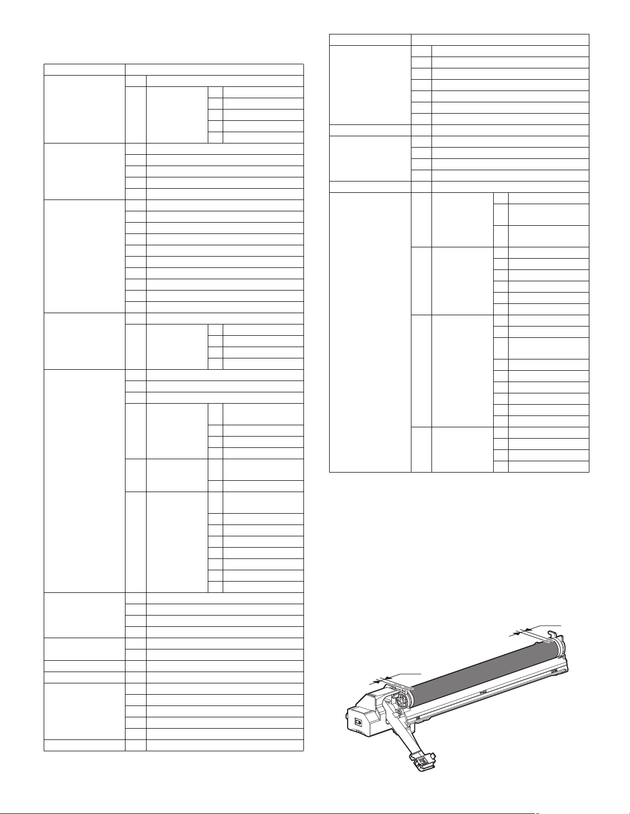
2. Details of Maintenance
5mm
5mm
Unit Parts
A. Process unit (1) Drum
(2) Drum section a. Main charger
B. Developing unit (1) Developer
(2) Toner filter unit
(3) DV side sheet F/ DV side sheet R
(4) DV blade
(5) Toner sensor
C. Fusing section (1) Thermostat
(2) Thermistor
(3) Paper guide
(4) Fusing separation pawl (lower)
(5) Lower heat roller
(6) Heater lamp
(7) Upper cleaning pad
(8) Fusing separation pawl (upper)
(9) Upper heat roller
(10) Thermistor cleaning pad
D. Optical section (1) CCD unit
(2) Lamp unit a. Lamp
E. Paper feed
section
F. Side door unit (1) Transport roller unit
G. 1st paper exit unit (1) Cooling fan
H. Laser unit (1) LSU
I. Power unit (1) Power source
J. PWB (1) Option CN PWB
K. Ozone filter
(1) Paper feed solenoid
(2) Tray sensor PWB
(3) Manual P-in sensor/Manual empty sensor
(4) Multi manual
paper feed
(5) Upper 500
sheets tray
paper feed
(6) Lower 500
sheets tray
paper feed
(2) Transport roller
(3) DUP transport roller
(4) DUP motor
(2) Transport/exit roller
(2) IMC PWB
(3) MCU PWB
(4) Motherboard PWB
(5) Second interface PWB
b. Cleaning blade
c. Drum frame unit
d. Moquette F/R
e. Separation pawl
b. PWB
c. Wire
d. Mirror motor
a. Paper feed roller/
pickup roller
b. Reverse sensor
c. Separation sheet
d. Clutch/solenoid
a. Paper feed roller/
pickup roller
b. Separation sheet
a. Paper feed roller/
pickup roller
b. Separation sheet
c. Lift up unit
d. Transport clutch
e. Paper feed clutch
f. Transport clutch
g. Solenoid
h. Sensor PWB
Unit Parts
L. Drive section (1) DUP reverse motor
(2) Main drive motor
(3) Toner motor
(4) PS transport clutch
(5) Paper feed clutch
(6) Drive unit
(7) Lift up motor
M. Transport section (1) Transport roller
N. Operation section (1) Operation section
(2) OPU PWB
(3) Key PWB
(4) LCD unit
O. Switch (1) Power switch
P. RSPF (1) Document tray
section
(2) Paper feed unit
section
(3) Transport
section
(4) Base section a. Interface PWB
a. Document tray unit
b. Document length
sensor
c. Document width
resistor PWB
a. Paper feed clutch
b. Pickup roller
c. Paper feed roller
d. Paper feed unit
e. Separation sheet
f. Sensor
a. Transport unit
b. PS clu tch
c. Pressure release
solenoid
d. RSPF motor
e. Transport roller
f. Roller
g. Sensor
h. Roller
i. Roller
b. Solenoid
c. Book sensor
d. Sensor
A. Process unit
(Note for servicing the OPC drums)
1. Prevention of oily dirt attachment
Note:
• Be careful not to attach fingerprints or oily dirt on the OPC drum surface. (Keep the unit away from oils and dust.)
• When replacing the OPC drum, cover the OPC drum with the protection sheet and hold the protection sheet.
If it is required to hold the OPC drum directly, use enough care not to
touch the cleaning blade area, 5mm inside from both edges of the
OPC drum. (If a fingerprint or oily dirt is attached to the cleaning
blade area of the OPC drum, the cleaning blade may flip.)
AR-5726/5731 MAINTENANCE 8 - 3
Page 83
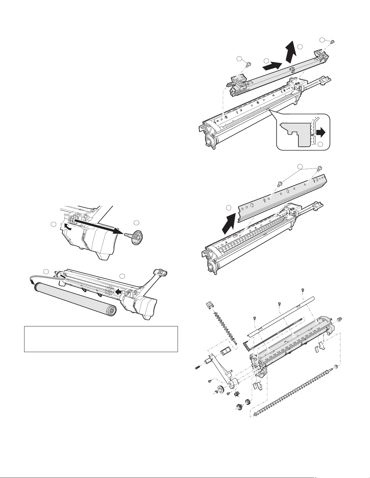
[Countermeasures]
2
1
4
3
1
2
4
3
1
1
2
If a fingerprint is attached to the OPC drum surface erroneously,
perform the following countermeasures.
1) Use dry cloth to clean and remove the dirt.
2) Apply KYNAR to prevent blade flip.
[Check method]
Check to confirm that the OPC drum is free from fingerprints or oily dirt
and that the cleaning blade is completely cleaned by the following
method.
• Make a print of a half tone image on all the surface of A4 (11" x 8.5")
paper, and check the printed paper for any abnormality in the image.
2. Prior exposure prevention
Note:
• Avoid servicing in a place where there is strong light.
• Do not expose the unit to light for a long time.
• Cover the OPC drum with light-blocking material. (When using
paper, use about 10 sheets of paper to block light.)
[Countermeasures]
If the OPC drum is erroneously exposed to light too much (prior exposure), perform the following countermeasures.
1) Print half tone images on the whole surface of A4 (11" x 8.5")
paper, and check to confirm that there is no irregular density area
in the previously exposed section.
2) Damages due to prior exposure may be recovered by keeping the
OPC drum for several hours. If, however, image are not recovered,
replace the OPC drum.
(1) Drum
(2) Drum section
a. Main charger
b. Cleaning blade
Note: When installing the process unit in the main unit after replacing
the drum, process unit may not be able to install by reason of the
drum drive coupling position.
In this case, rotate the drum about 45 degrees and install again.
c. Drum frame unit
AR-5726/5731 MAINTENANCE 8 - 4
Page 84
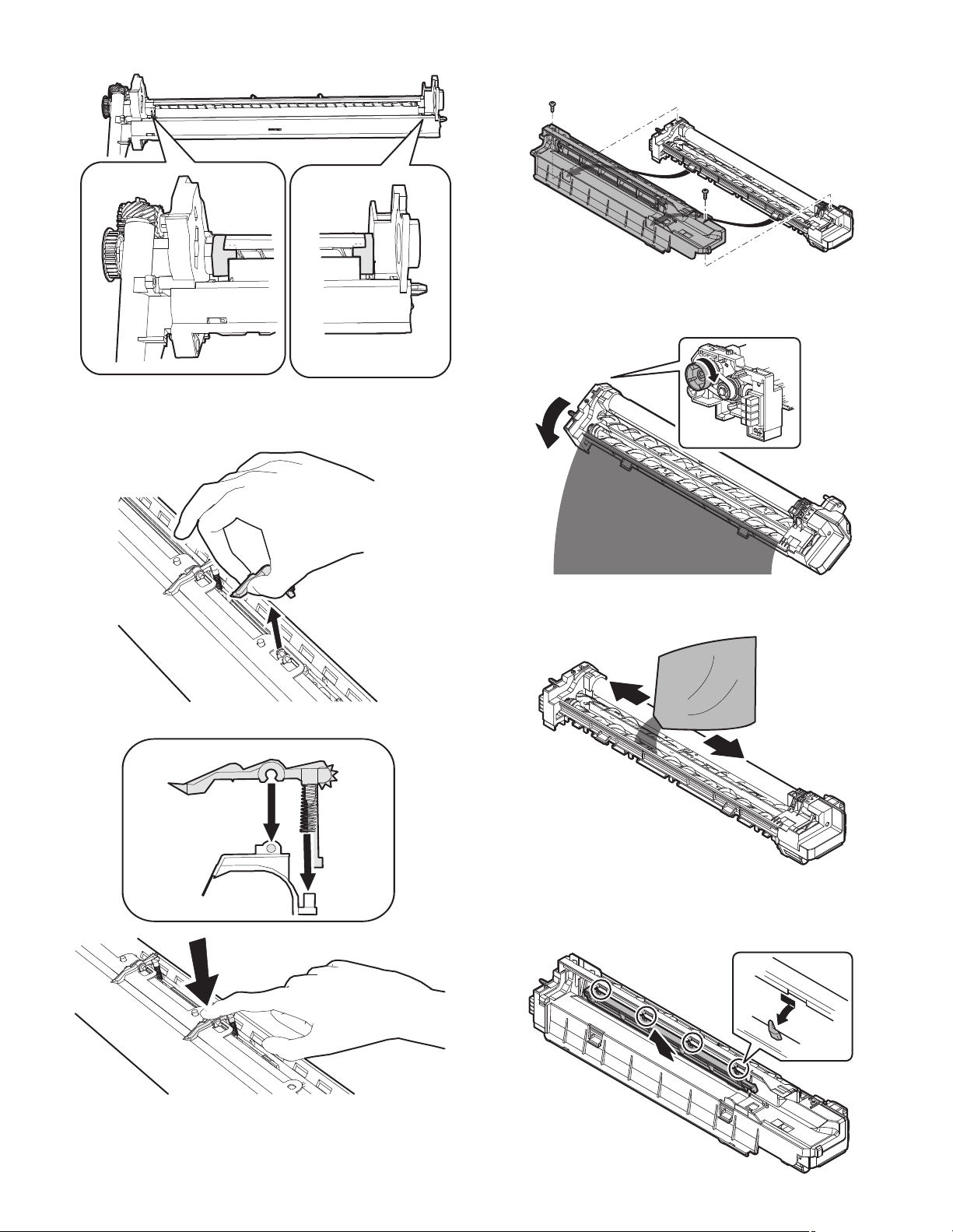
d. Moquette F/R
Note: If it disturbs the blade movement, replace it and attach new one.
e. Separation pawl
Disassembly* Hold the tip of the separation pawl and remove it.
B. Developing section
(1) Developer
Rotate the MG roller to discharge developer.
Assembly* Press the center of the separation pawl and install it.
(2) Toner filter unit
With the guide AS (cover) removed, replace it.
When replacing, clean the guide AS.
AR-5726/5731 MAINTENANCE 8 - 5
Page 85
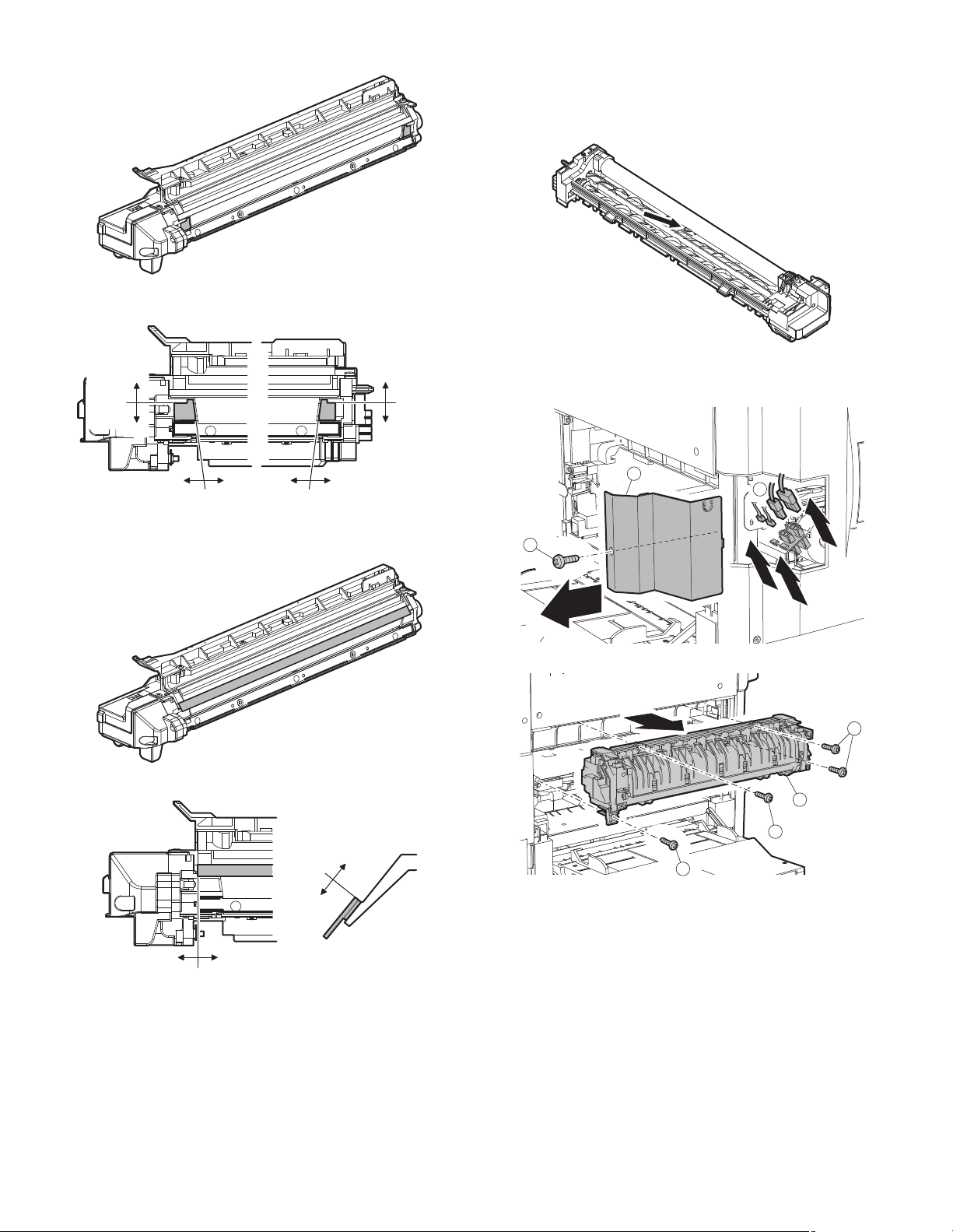
(3) DV side sheet F/ DV side sheet R
00.5 0 0.5
0
0.3
0
0.3
Projection edge
reference
Projection edge
reference
Molt
edge
reference
Molt
edge
reference
1
1
1
2
[DV side sheet F/ DV side sheet R attachment reference]
(5) Toner sensor
• Execution of cleaning the sensor must be made after discharging
used DV in DV replacement.
• Without removing the MG roller, use waste cloth to remove toner
from the sensor surface in the arrow direction.
• Clean the sensor only after removing used DV when replacing DV.
C. Fusing section
2
3
(4) DV blade
[DV blade attachment reference]
0.5
Rib reference
0
[Cross-section]
Bump
reference
0.5
1
0
AR-5726/5731 MAINTENANCE 8 - 6
Page 86
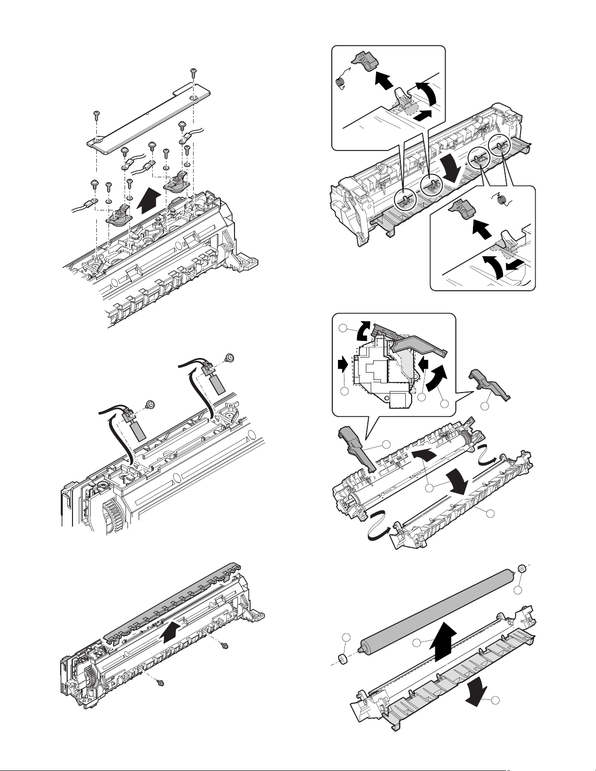
(1) Thermostat
1
2
2
3
4
4
5
6
2
1
3
3
Note: When securing the lamp harness and the thermostat, the
tightening torque of the screw (4 positions) is 6-9 kgs.
(4) Fusing separation pawl (lower)
(5) Lower heat roller
(2) Thermistor
(3) Paper guide
AR-5726/5731 MAINTENANCE 8 - 7
Page 87
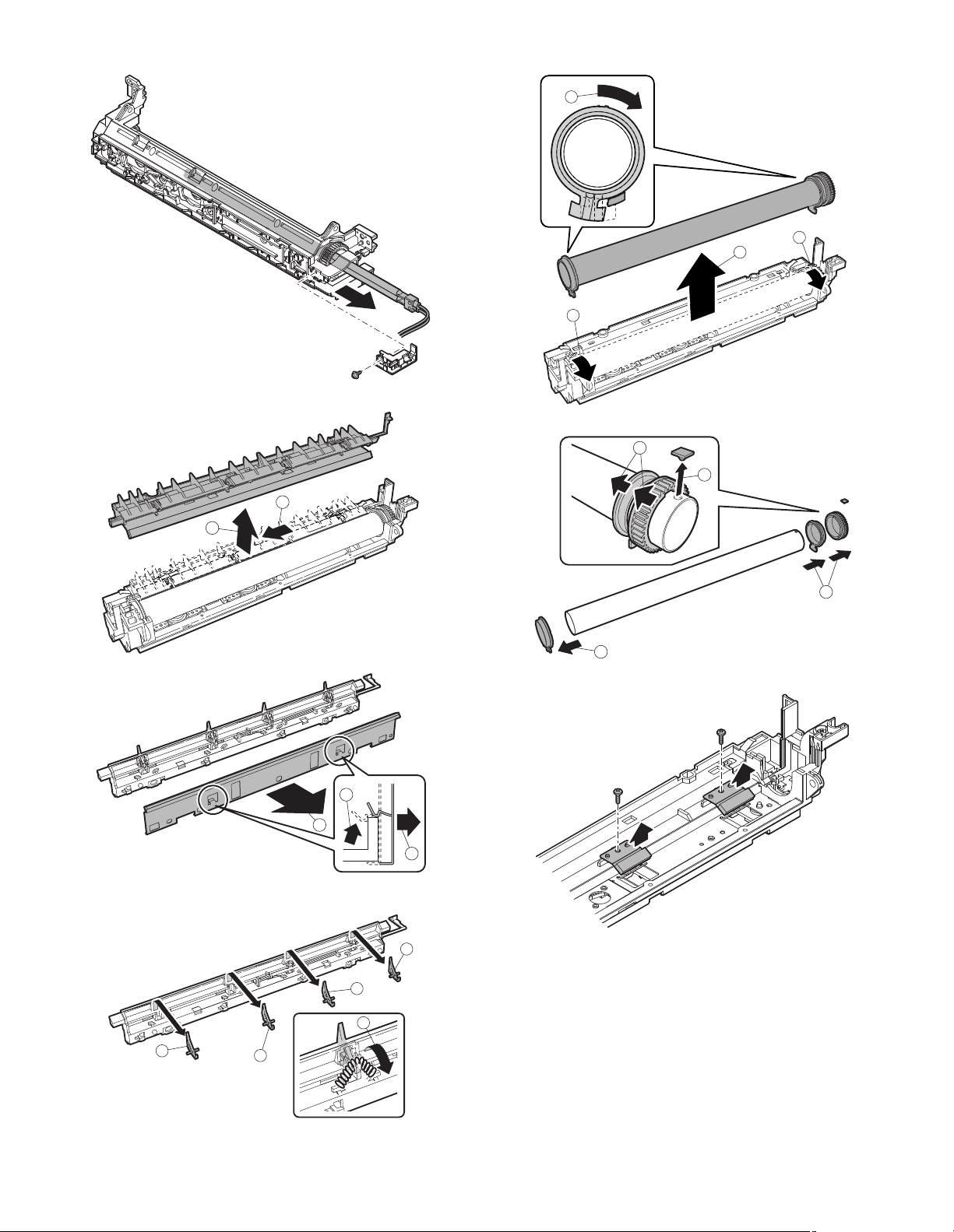
(6) Heater lamp
1
2
1
2
2
2
2
2
2
1
1
1
1
2
1
2
3
3
(7) Upper cleaning pad
(9) Upper heat roller
(8) Fusing separation pawl (upper)
(10) Thermistor cleaning pad
AR-5726/5731 MAINTENANCE 8 - 8
Page 88
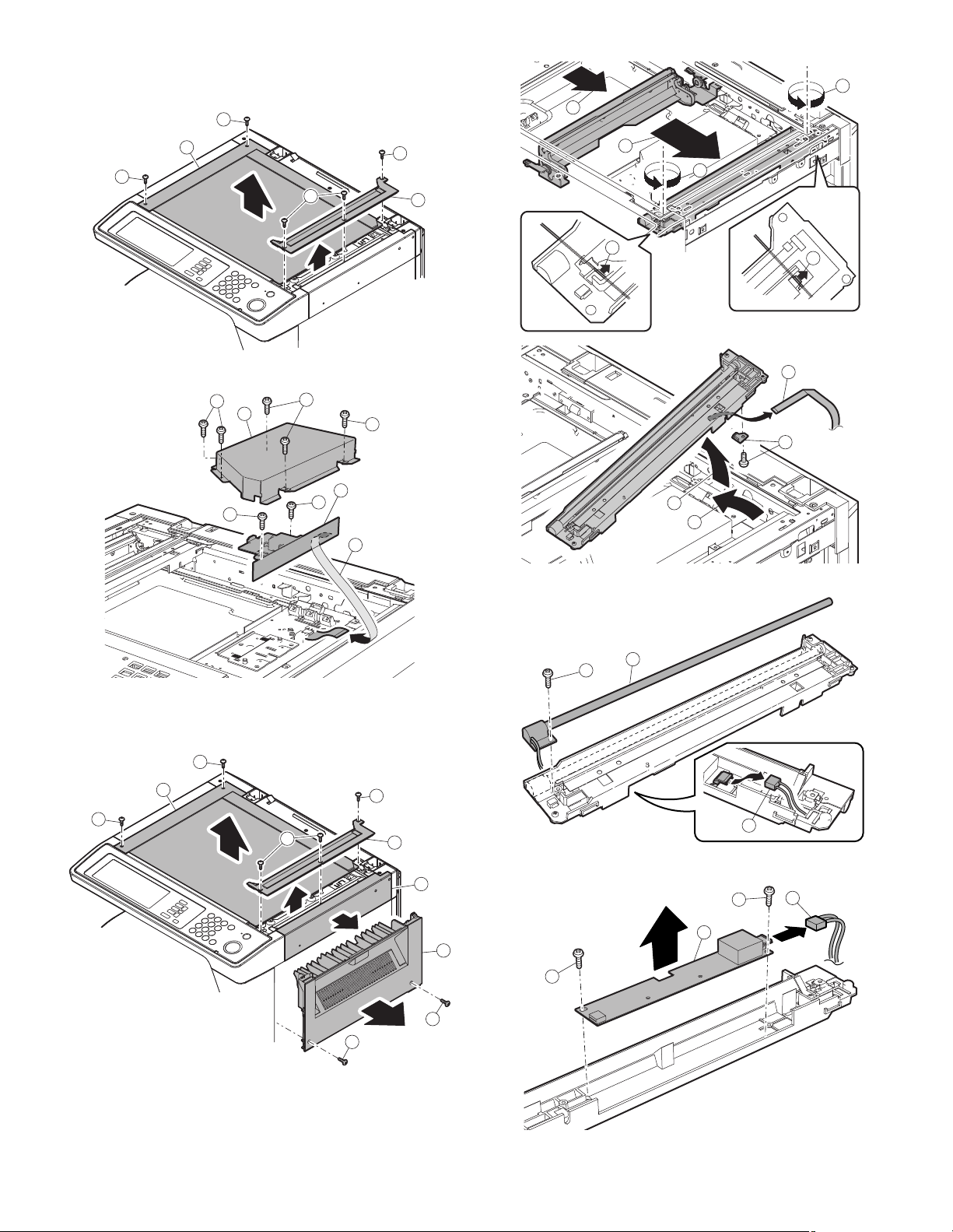
D. Optical section
4
4
5
1
1
1
2
3
1
1
2
2
3
3
4
1
2
3
1
2
3
1
2
2
3
(1) CCD unit
1
3
1
1
1
2
a. Lamp
(2) Lamp unit
1
1
3
1
1
2
b. PWB
6
5
4
4
AR-5726/5731 MAINTENANCE 8 - 9
Page 89
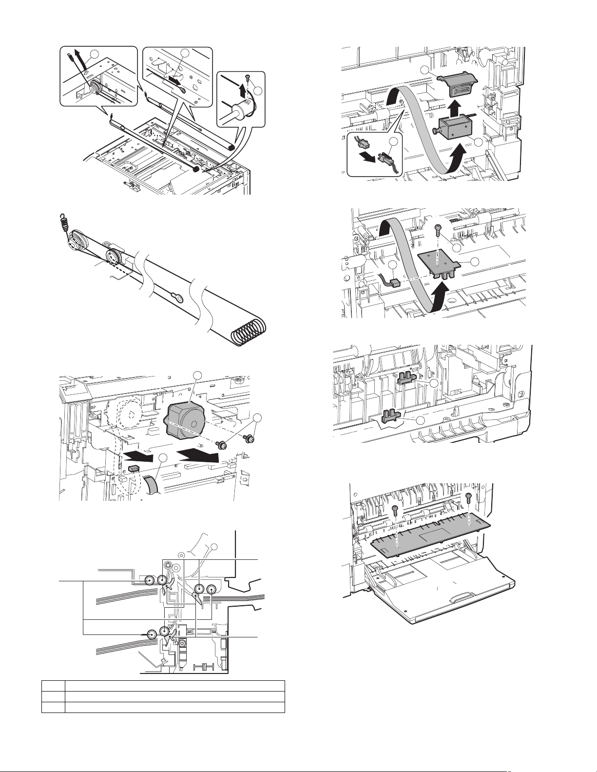
c. Wire
1
3
2
1
3
2
3
1
2
A
B
(1) Paper feed solenoid
1
3
2
(2) Tray sensor PWB
(3) Manual P-in sensor/Manual empty sensor
d. Mirror motor
E. Paper feed section
B
(4) Multi manual paper feed
a. Paper feed roller/pickup roller
A
C
A Paper feed roller
B Pickup roller
C Separation sheet
AR-5726/5731 MAINTENANCE 8 - 10
Page 90
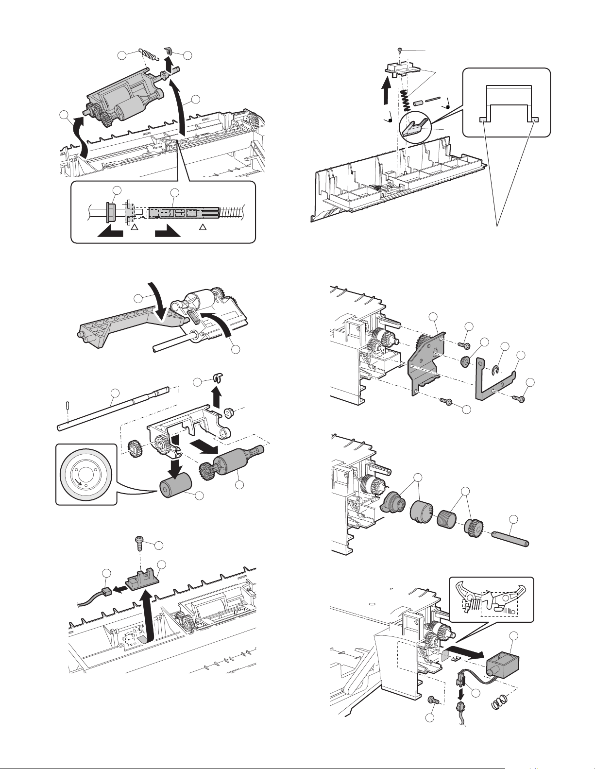
Installation*Install so that the cam transmit arm (1) comes under the
5
6
1 2
4
3
1
2
2
1
4
3
L
O
C
K
1
3
2
1)
2)
3)
4
5
5
6
3
1
2
1
2
2
3
1
2
roller arm (2).
c. Separation sheet
∗ Slightly apply grease GP501MR (UKOG-0012QSZZ) around the
axis. One rice grain for each.
d. Clutch/solenoid
(Clutch)
b. Reverse sensor
(Solenoid)
AR-5726/5731 MAINTENANCE 8 - 11
Page 91
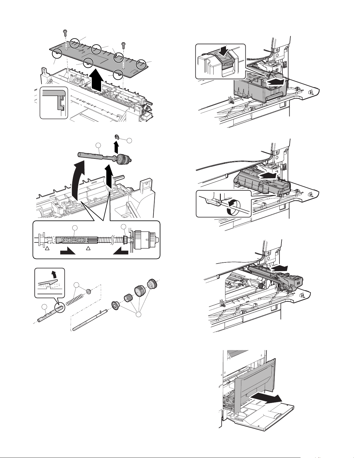
(Clutch)
A
A
A
A
A
A
A
4
1
2
3
(5) Upper 500 sheets tray paper feed
a. Paper feed roller/pickup roller
2
1
3
AR-5726/5731 MAINTENANCE 8 - 12
Note: With the toner cartridge installed, do not tilt or shake the devel-
oper cartridge.
Page 92
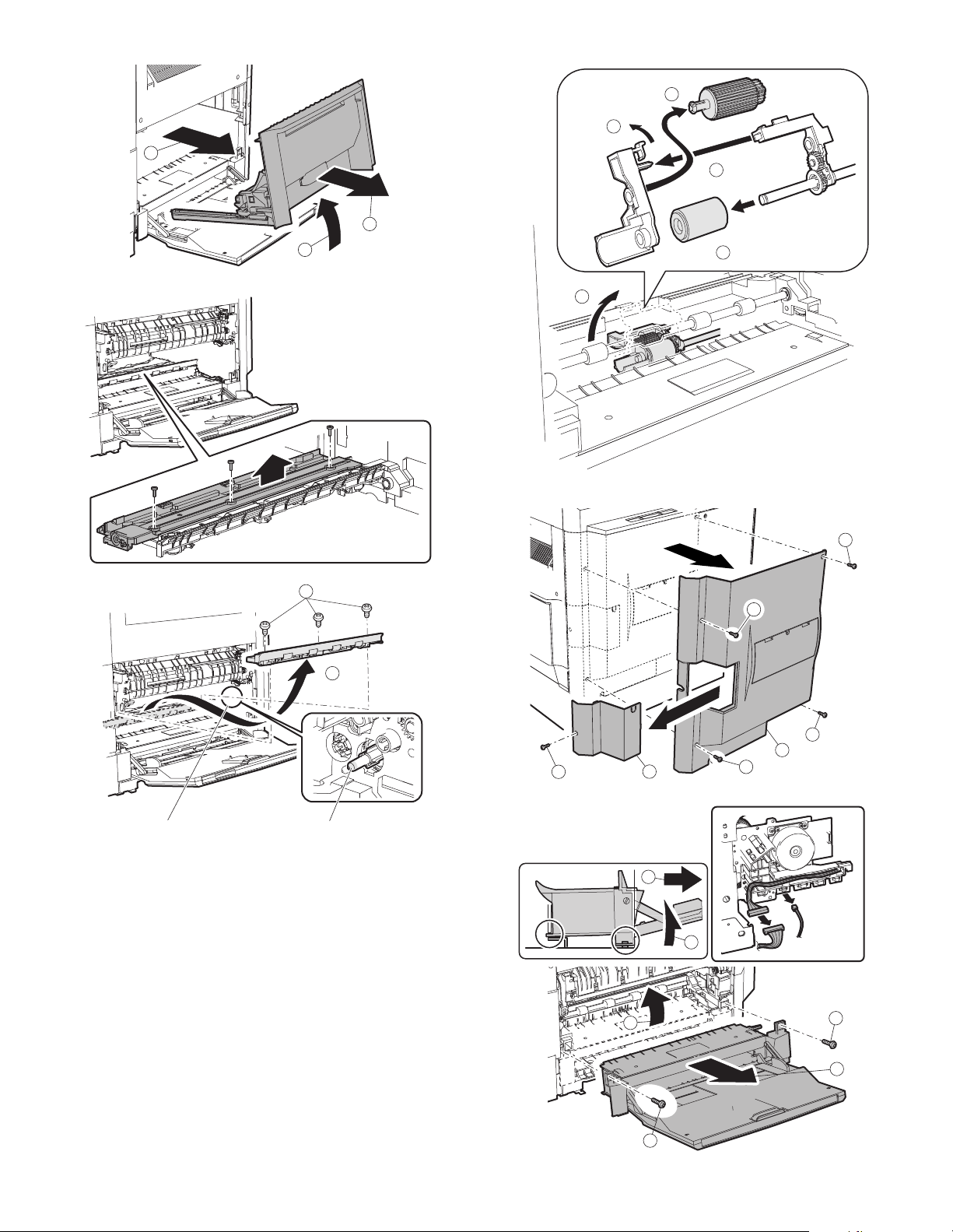
1
2
4
1
2
3
4
3
3
3
2
1
3
3
2
4
1
b. Separation sheet
∗ When replacing, be careful not
to adhere conduction grease
(black) to the drive section.
Slightly apply grease GE676
(UKOG-0013QSZZ) to the
drum boss.
3
2
2
1
3
1
AR-5726/5731 MAINTENANCE 8 - 13
Page 93
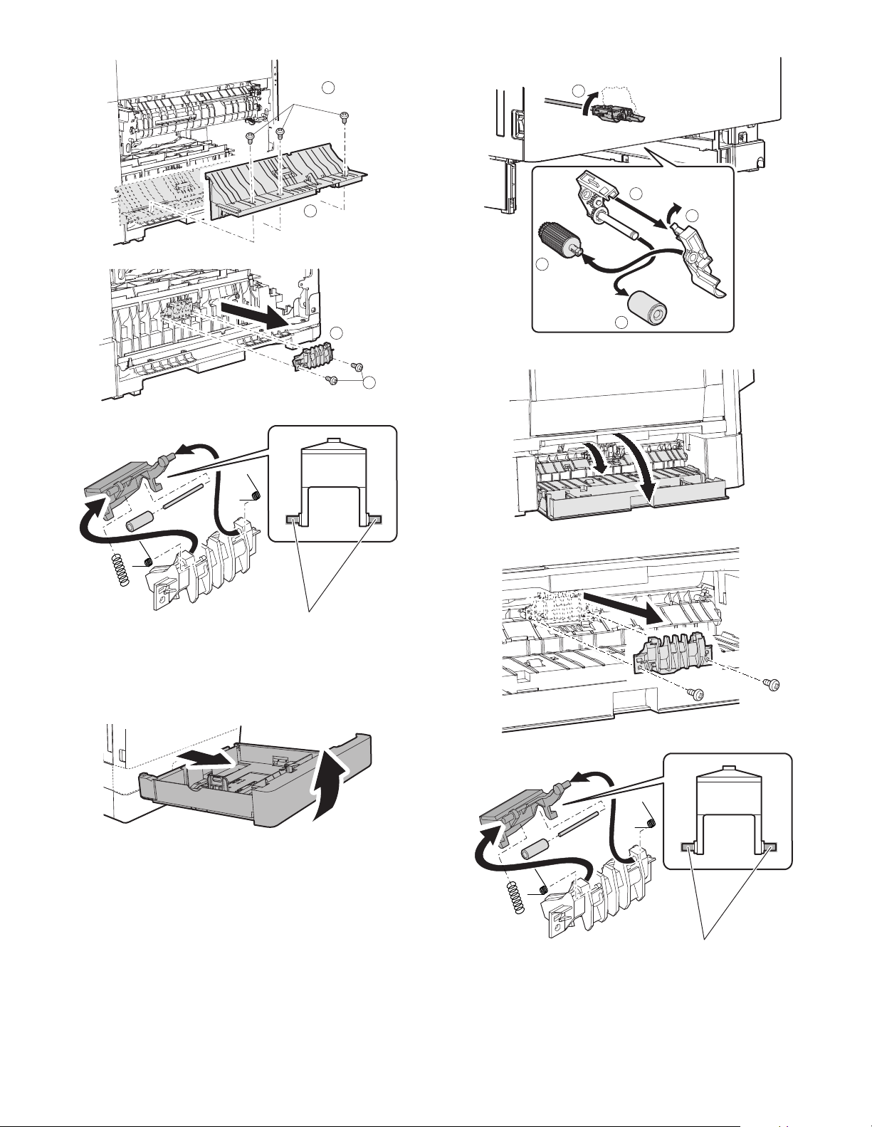
1)
1
2
1
3
2
4
2
1
∗ Slightly apply grease GP501MR (UKOG-0012QSZZ) around the
axis. One rice grain for each.
Grease should not come out when assembling.
(6) Lower 500 sheets tray paper feed
a. Paper feed roller/pickup roller
4
b. Separation sheet
∗ Slightly apply grease GP501MR (UKOG-0012QSZZ) around the
axis. One rice grain for each.
Grease should not come out when assembling.
AR-5726/5731 MAINTENANCE 8 - 14
Page 94
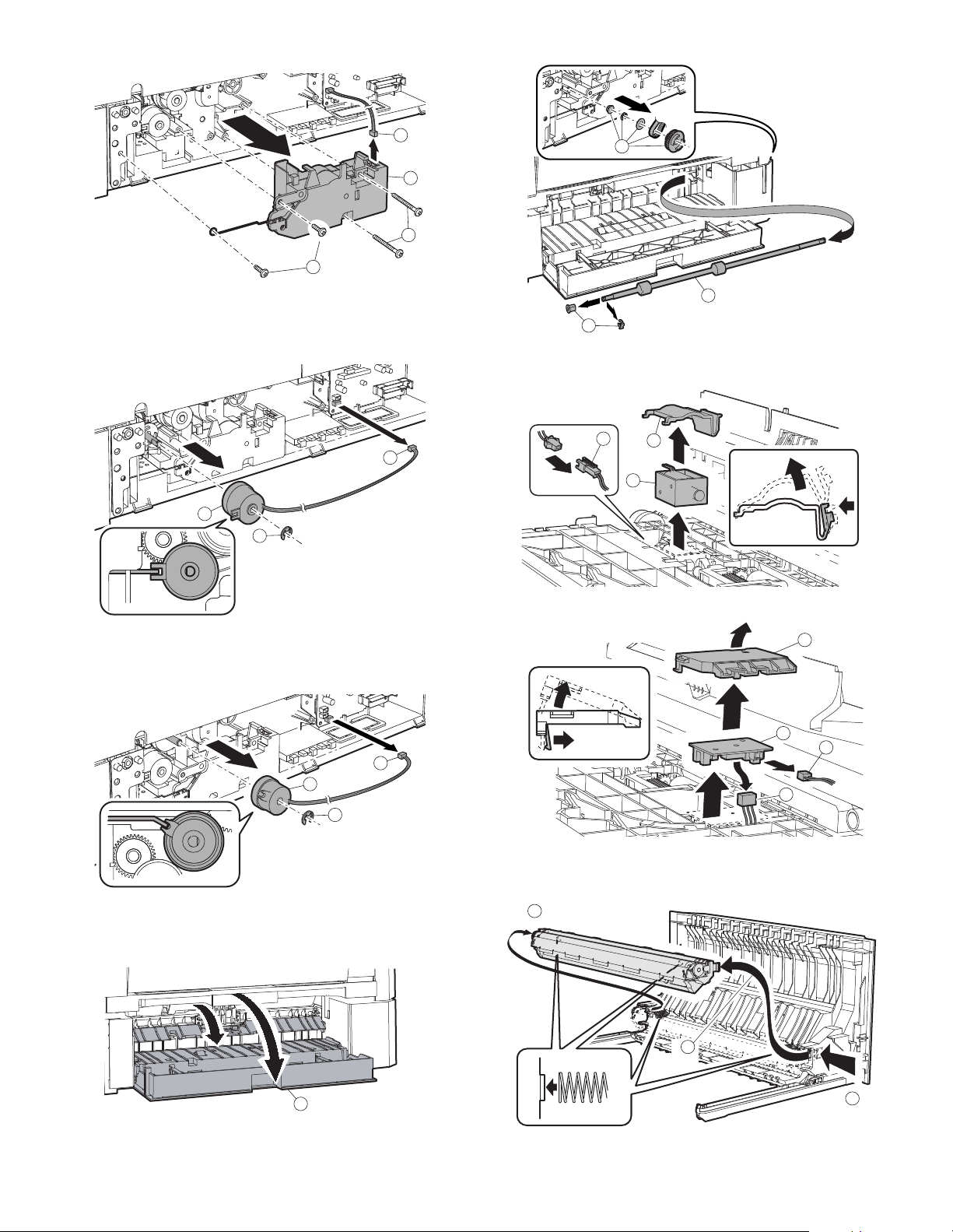
c. Lift up unit
1
2
1
1
1
3
2
1
1
2
3
1
2
3
3
1
2
3
d. Transport clutch
e. Paper feed clutch
g. Solenoid
1
3
2
h. Sensor PWB
1
3
f. Transport clutch
2
F. Side door unit
(1) Transport roller unit
AR-5726/5731 MAINTENANCE 8 - 15
∗ Check that two springs are securely inserted into the transfer roller
unit bosses.
Page 95
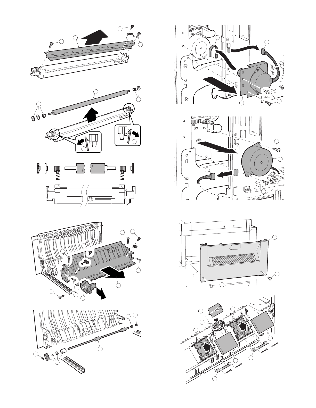
(2) Transport roller
1
1
1
2
1
1
2
3
3
4
2
3
3
3
3
3
3
1
1
1
3
2
2
1
2
3
4
1
2
3
2
1
1
2
(4) DUP motor
G. 1st paper exit unit
(3) DUP transport roller
AR-5726/5731 MAINTENANCE 8 - 16
(1) Cooling fan
5
3
4
1
5
2
2
1
Page 96
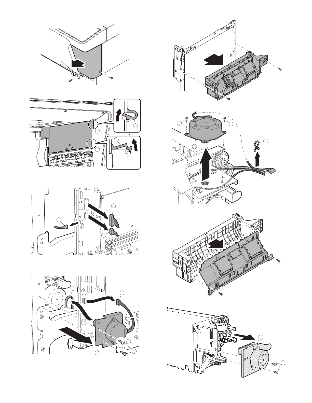
(2) Transport/exit roller
1
2
3
4
1
2
3
2
1
2
(Except North America)
2
2
11
1
1
1
1
AR-5726/5731 MAINTENANCE 8 - 17
Page 97
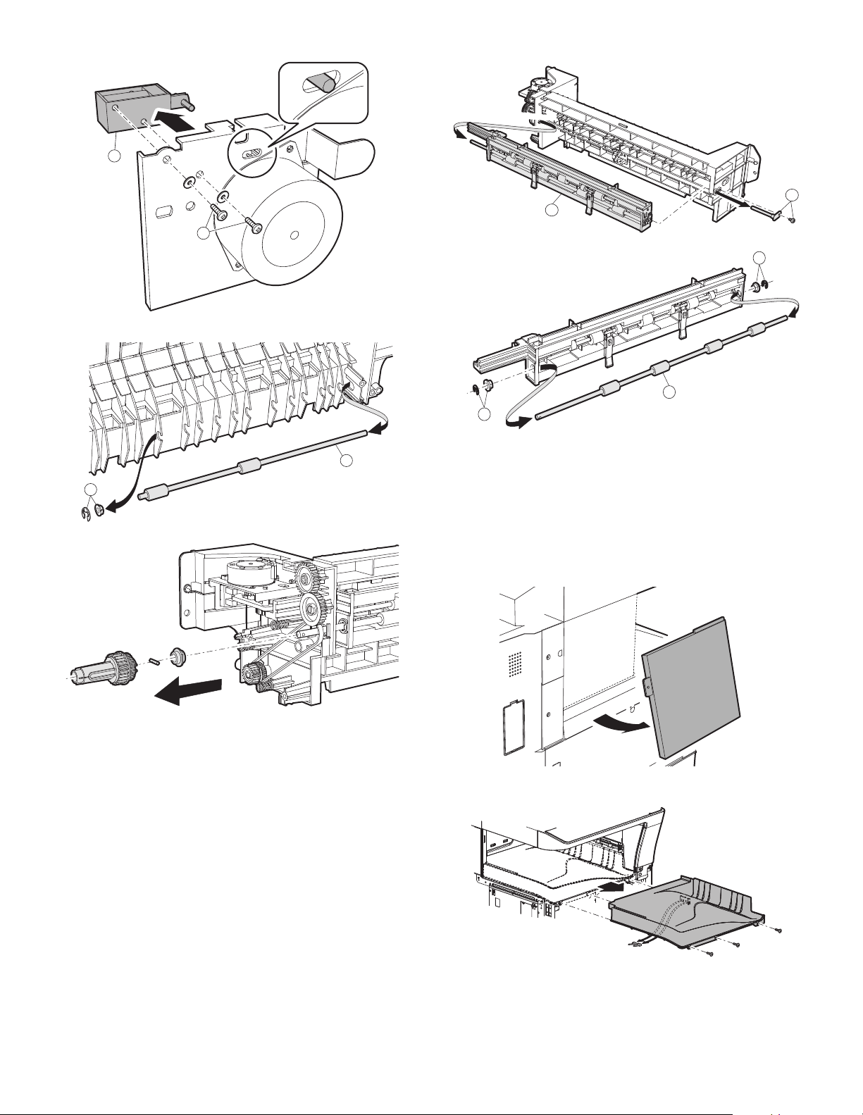
2
1
2
1
1
1
2
1
1
H. Laser unit
Note: Do not disassemble the LSU unit.
(1) LSU
1) Turn OFF the machine power, and disconnect the power plug from
the power outlet.
2) Remove the left cabinet and exit tray.
3) Disconnect the LSU connector, and remove the securing screws to
remove the LSU.
Note: Check to confirm that the solenoid shaft is in the gate bracket,
and fix with the screw.
AR-5726/5731 MAINTENANCE 8 - 18
Page 98
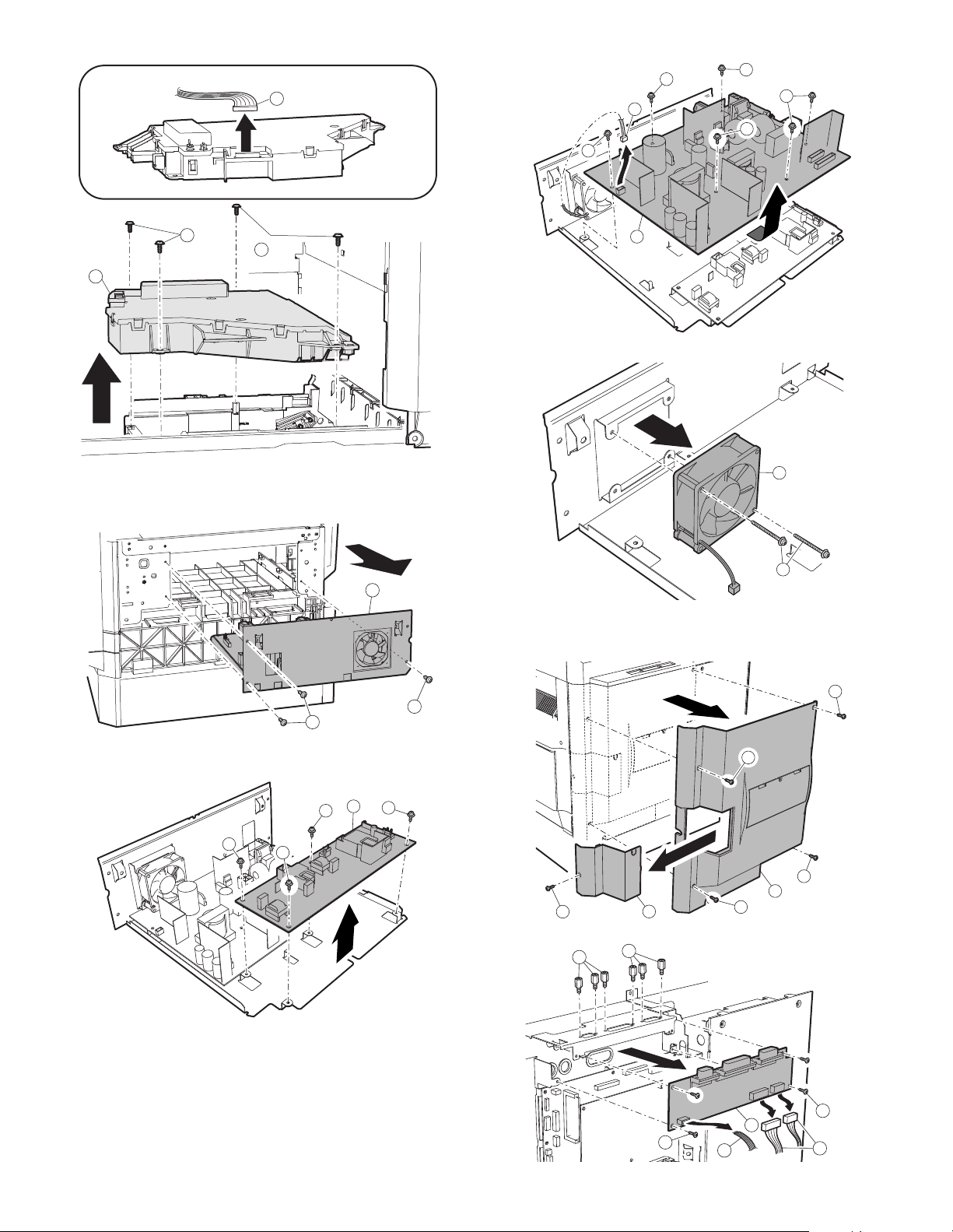
I. Power unit
1
2
2
3
1
1
2
1
2
1
1
1
1
2
3
2
2
2
2
1
2
3
4
3
3
3
2
2
2
3
1
1
2
(1) Power source
2
1
J. PWB
(1) Option CN PWB
AR-5726/5731 MAINTENANCE 8 - 19
Page 99
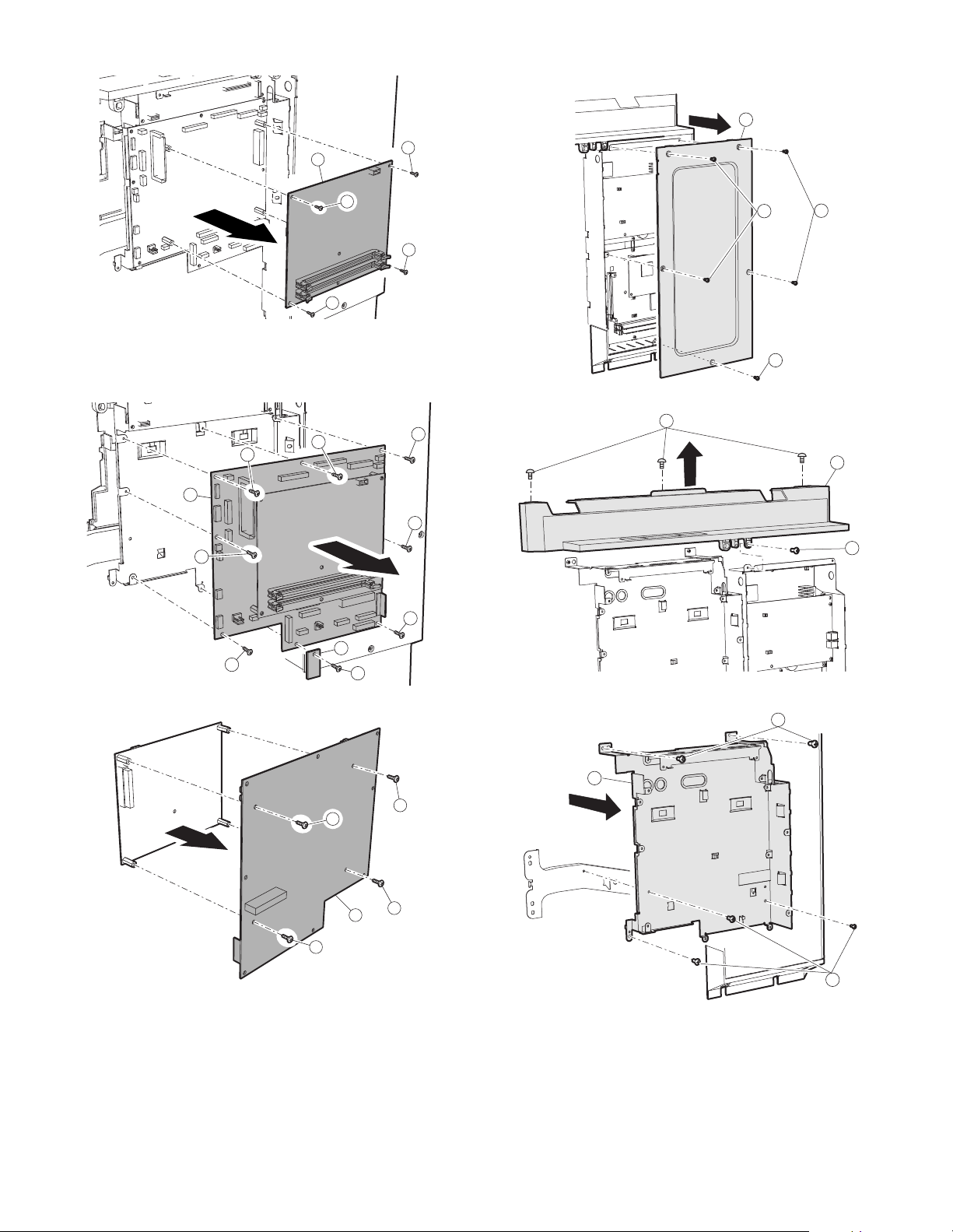
(2) IMC PWB
3
3
3
3
4
3
1
3
2
3
1
1
2
1
1
1
1
1
2
1
2
1
1
1
2
(4) Motherboard PWB
(3) MCU PWB
2
1
1
1
1
AR-5726/5731 MAINTENANCE 8 - 20
Page 100
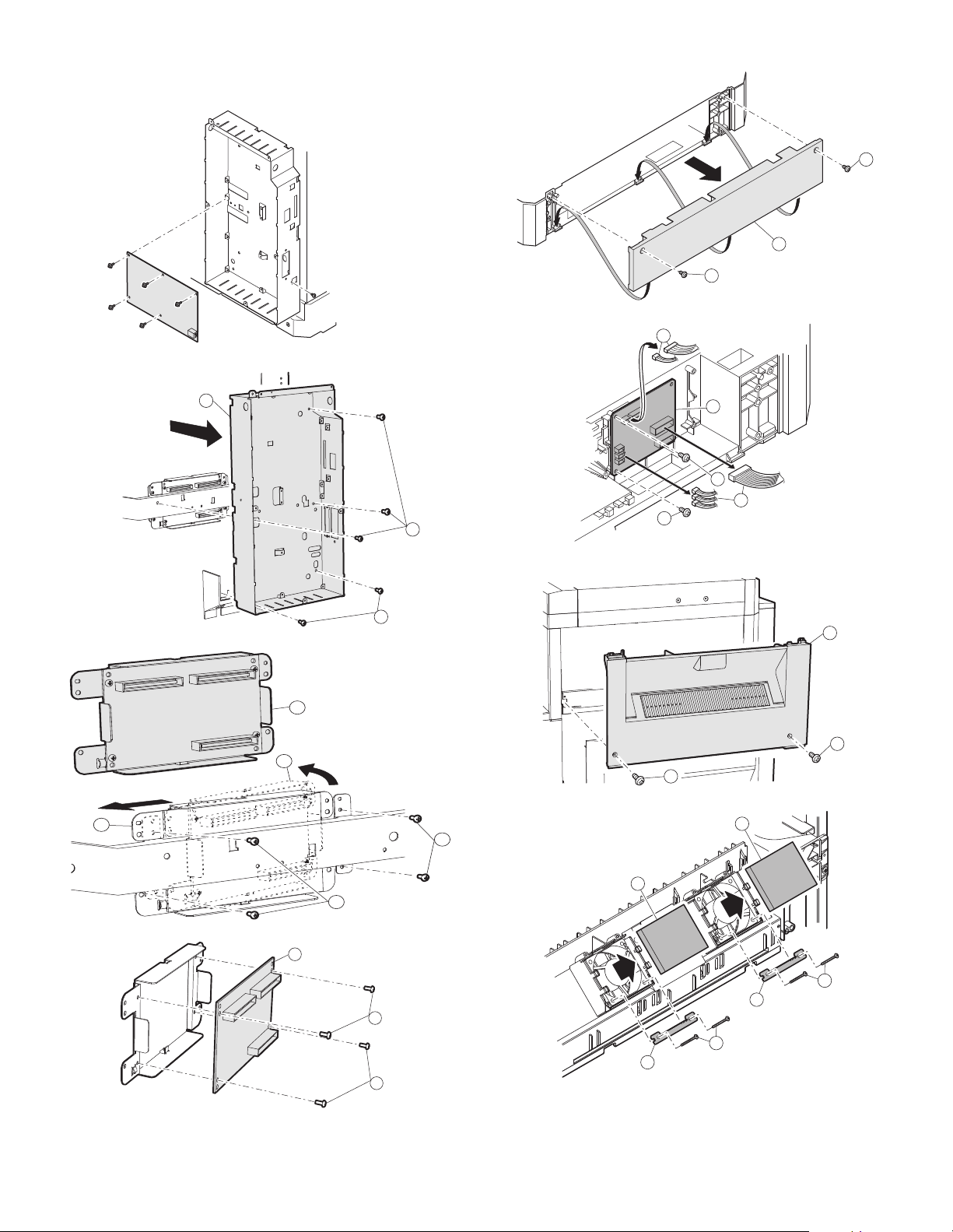
(5) Second interface PWB
1
1
2
4
3
2
1
1
1
1
2
2
1
1
1
1
2
2
3
K. Ozone filter
2
1
1
3
3
1
2
2
1
AR-5726/5731 MAINTENANCE 8 - 21
 Loading...