

Page 1

Thank You For
Purchasing This DVD
Collection! If You Did
NOT Purchase This
Document As Part Of A
DVD Collection From
RushAZ85705 on E-Bay,
This Document Has
Been Passed
Fraudulently! Please
Alert
RushTalion@Cox.Net !
Thank You Again!
Page 2
SERVICE MANUAL
CODE : 00ZAR800//A1E
DIGITAL COPIER
MODEL
CONTENTS
[ 1 ] SPECIFICATIONS•ACCESSORIES•OPTIONS•SUPPLIES. . . 1 - 1
[14] FUSER UNIT. . . . . . . . . . . . . . . . . . . . . . . . . . . . . . . . . . . . . . 14 - 1
AR-800
(Maintenance tables)
Parts marked with “ “ are important for maintaining the safety of the set.
Be sure to replace these parts with specified ones for maintaining the safety and performance of the set.
This document has been published to be used for
SHARP CORPORATION
after sales service only.
The contents are subject to change without notice.
Page 3

Page 4

GENERAL
The major differences between the AR-800 and the AR-650 are
described below.
1. Specifications
The major differences between the AR-800 and the AR-650
lie in the copy (print) speed and the maintenance cycle.
(Max. copy (print) speed)
AR-650: 65CPM (PPM)
AR-800: 80CPM (PPM)
The process speed is the same, but the paper feed interval
differs.
(Maintenance cycle and consumable parts replacement cycle)
AR-650: Every 400K
AR-800: Every 440K
2. Hardware
Differences between the AR-800 and the AR-650
1) The PWA-F-LGC PWB differs.
AR-650: PWA-F-LGC-300
AR-800: PWA-F-LGC-304
(Different parts): Connector, EEPROM, FLASH ROM
The above two PWBs are not compatible each other.
2) Front cabinet
3) Model badge
3. Options
The AR-P13 (printer unit) is also revised for either of two
models, the AR-650 and the AR-800.
The differences between the old and new versions are as
follows:
(AR-P13 for AR-650)
Characters printed on the packing case are in black.
Firmware version: 1.43
Software version: (CD-ROM) 1.10
(Printed on the packing case)
(AR-P13 for AR-650/800)
Characters printed on the packing case are in blue.
Firmware version: 1.44
Software version: (CD-ROM) 1.20
(Printed on the packing case)
The service documents are based on the above contents.
A. Service manual
Chapter 1. SPECIFICATIONS, ACCESSERIES, OPTIONS,
SUPPLIES
Comprehensive contents of the AR-800 and the AR-650
(Complete version)
Chapter 14. FUSER UNIT
Since the temperature control of the fusing section on page
14-5 differs between the AR-800 and the AR-650, the
temperature control of the AR-800 is added.
Only the contents of page 14-5 are described.
B. Actual wiring diagram
Since the PWA-F-LGC-304 (for AR-800) is newly employed,
the connector wiring is changed and the actual wiring
diagram is changed. The actual wiring diagram for the AR800 is newly prepared.
C. Service Handbook
Though the maintenance cycle and the consumable parts
replacement cycle differ between the AR-800 and the AR650, the contents of the Service Handbook are not changed.
Be sure to note the maintenance cycle of both models for
servicing.
AR-650: Every 400K
AR-800: Every 440K
D. Parts Guide
Only the different sections between the AR-650 and the AR800 are prepared.
Sections 1, 2, 5, 6, 13, 31, 39, 47, 62, 86, 101, 203, 204
(including the contents of both models, AR-800/AR-650)
For servicing of the AR-800, use these documents as well
as the service document of the AR-650.
4. Others
The temperature control in the fusing section differs between
the AR-650 and the AR-800.
Except the above, the AR-800 and the AR-650 are the same.
Page 5
1. SPECIFICATIONS • ACCESSORIES • OPTIONS • SUPPLIES
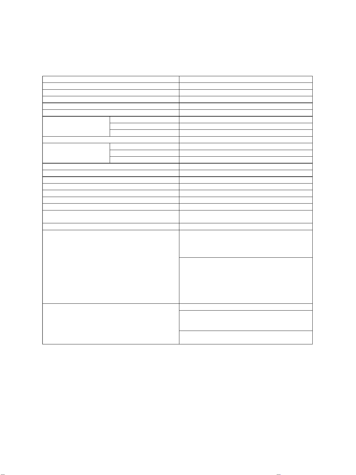
1.1 Specifications
1. System
Copy system Indirect electronic photo system (Dry type)
Body type Console type
Original table type Fixed type (Left center reference)
Original cover RADF standard provision
Frame structure Fixed frame type
Photoconductor OPC drum (ø100)
Original scan system
Scan data output system 1-scan multi-copy system
Exposure system
Developing system 2-component magnetic brush developing system
Discharging system Photo discharging by red LED
Charging system Negative corona system (Scorotron)
Transfer system Transfer belt system
Separation system Transfer belt system
Transfer belt cleaning system Fur brush system + Blade system
Drum cleaning system Blade system + Fur brush system
Toner supply system Toner hopper system, right top side toner bottle supply
Toner density adjustment system Magnetic auto toner system
Toner empty detection system
Scan sensor CCD line sensor (7500 pixel)
Scan resolution 600 x 600dpi
Scan light source Halogen lamp (180W)
Exposure light source Semiconductor laser
Exposure resolution 600dpi
Scan system Using polygon mirror
system
1. Mechanical sensor system
Note 1: When detecting, the toner supply lamp flashes.
Fusing system
2. Electrical system (Using auto toner sensor)
Note 1: When detecting toner empty, the toner supply
lamp flashes and the message is displayed.
Heat roller system
Infrared heater (Upper) 2 pcs.
700W + 600W
Roller dia. (Upper) ø 60mm
Roller dia. (Lower) ø 60mm
1 - 1 SPECIFICATIONS
Page 6
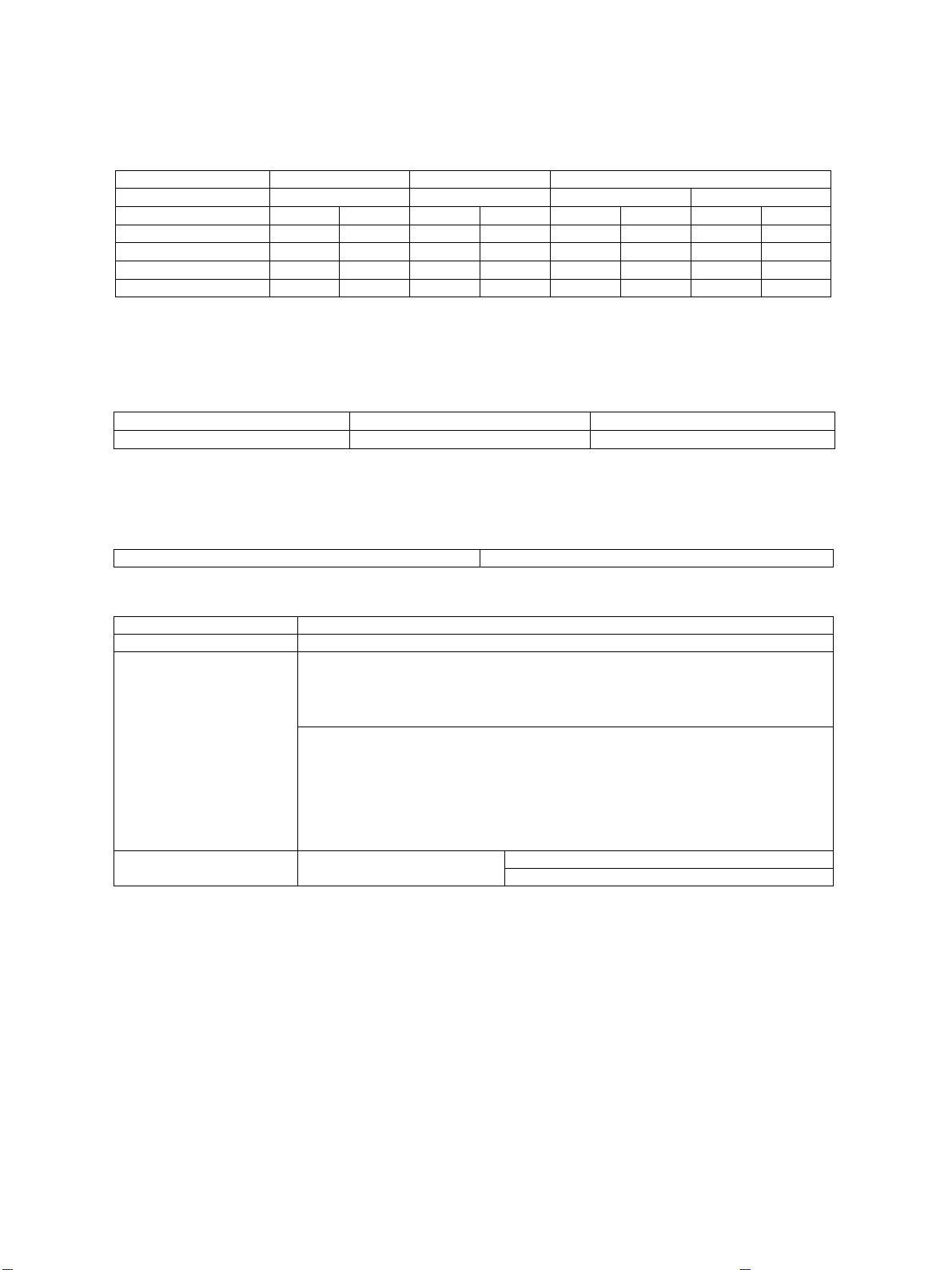
2. Basic specifications
A. Copy speed
(1) Continuous copy
Paper feed system
Paper size
A4,B5,A5-R,LT,ST-R
A4-R,B5-R,LT-R
B4,FOLIO,LG,COMP
A3,LD
AR-650
65(55)
-
-
-
LCF
AR-800
80
-
-
-
Cassette
AR-650
65
51
44
38
AR-800
74
61
52
43
Size specified
AR-650
48
42
37
33
Note 1: The above specifications are for manual feed, single and continuous copy.
Note 2: The state which is other than the toner supply mode.
(2) First copy
AR-650
First copy time
3.9sec or less
Note 1: The above specification is for manual feed, normal size, A4/LT size, LCF feed.
Note 2: When APS is not used.
B. Warming up time
Normal About 420sec at 20°C
C. Original
Max. size A3 or LD
Kind Sheet, cubic material, book
Original size detection
Glass surface: Provided
Note 1: Fixed detection system with the platen cover open
Manual feed
AR-800
48
42
37
33
3.6sec or less
Size not specified
AR-650
33
33
33
33
AR-800
AR-800
33
33
33
33
RADF: Provided
Note: The original width and length are detected in RADF feed.
Note 2: Only the first sheet is detected except when the mixed original mode is
selected.
Fixed size
auto detection
SPECIFICATIONS 1 - 2
AB series: A3,A4,A4-R,A5-R,B4,B5,B5-RAllowable original size for
LT series: LD,LG,LT,LT-R,ST-R
Page 7
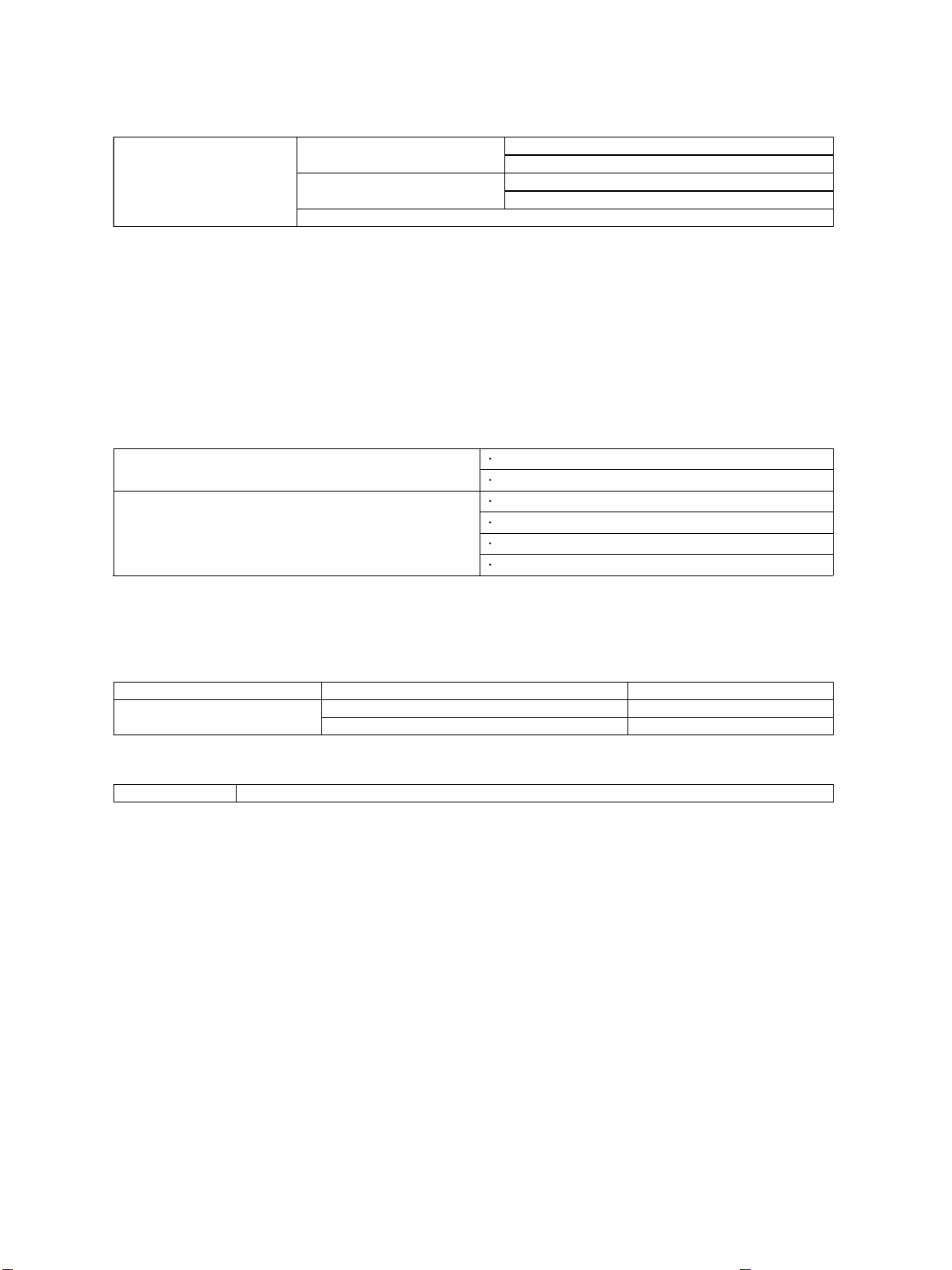
D. Paper
(1) Size
Fixed size
Cassette
AB series: A3,A4,A4-R,A5-R,B4,B5,B5-R,FOLIO
LT series: LD,LG,LT,LT-R,ST-R,COM
AB series: A3,A4,A4-R,A5-R,B4,B5,B5-R,FOLIOSFB
LT series: LD,LG,LT,LT-R,ST-R,COM
LCF : A4,LT,B5
Note 1: Postcards cannot be used.
Note 2: Name cards cannot be used.
Note 3: Same surface copy cannot be used.
Note 4: Envelopes cannot be used.
Note 5: The paper width of fixed size is detected with the manual tray guide width.
Note 6: The upper stage of B5 cassette cannot be used.
Note 7: SFB mixed size paper cannot be used.
(2) Kind
Cassette
LCF
PPC paper
SFB
PPC paper
Tracing paper: Out of warranty
OHP film: Out of warranty
Label sheet: Out of warranty
Note 1: Only one sheet feed is allowed except for PPC paper.
Note: Special paper such as postcards and PPC paper with punch holes cannot be used.
(3) Weight
Cassette, LCF 64~ 80 g/m2,17~ 22 lbs
64~ 80 g/m2,17~ 22 lbs Continuous feed allowedSFB
80~157g/m
2
,22~ 41 lbs Only one sheet feed allowed
(4) Curl level
Curl level PPC paper: The highest point when paper is put on a flat surface must be 5mm or less.
1 - 3 SPECIFICATIONS
Page 8
E. Paper feed
Paper feed means
LCF
Cassettes: 3 steps (Drawers of the copier)
SFB
Capacity
LCF: 4,000 sheets (Load height: max. 415mm)
Cassette: 500 sheets (Load height: max. 55mm)
SFB: 100 sheets (Load height: max. 11mm)
Note 1: 50 sheets for SFB duplex copy.
Note 2: However, the cassette load height is displayed as
53mm.
Note 3: however, the SFB load height is displayed as 10mm.
Manual feed start Start key start
Priority feed means LCF priority
Note 1: By data input of the adjustment mode, another paper
Factory setup: LCF
priority
feed means can have priority to be selected.
Manual feed size
specification
After setting paper, press the paper size key to specify the
paper size.
Note 1: By specifying the paper size, the binding margin,
duplex edge erase, and continuous page copy can be
performed. For APS and AMS, invalid.
F. Continuous copy
No. of sheets Increment of 1 sheet up to max. 999 sheets
Input system 10-key input
Count system Reduction system
Note 1: “1”is displayed in auto clear and warming up.
G. Density adjustment
Auto density adjustment Available
Manual density adjustment 11-step adjustment (Operated with
keys on the control panel LCD)
Priority mode Auto density adjustment
Factory setup: Auto
Note 1: By data input of the adjustment
mode, selection of auto/manual is
allowed.
H. Picture quality mode
Picture process mode Standard/Photo/Text mode
Priority mode Standard mode
Note: By data input of the adjustment mode, the mode can be selected.
I. Magnification ratio
(1) Reduction and enlargement
Reduction and enlargement Auto setup system depends on selecting
size and paper size.
Note 1: A desired fixed-size series (including a different
series) can be selected: Japan A5, UNIVERSAL,
OTHER.
the original
SPECIFICATIONS 1 - 4
Page 9

(2) Selected magnification ratio
a. AB series
Paper
A3 B4 FOLIO A4 B5 A5
Original
A3 100 86 71 71 61 50
B4 115 100 82 82 71 57
FOLIO 127 110 100 90 78 63
A4 141 122 100 100 86 71
B5 163 141 115 115 100 82
A5 200 173 141 141 122 100
b.LT series
Paper
LD COMP LG LT ST
Original
LD 100 82 78 65 50
COMP 108 100 84 78 54
LG 121 100 100 78 60
LT 129 119 100 100 65
ST 200 165 154 129 100
Note 1: The above numbers show magnification ratios.
(3) Other
Zoom 20 – 400%, increment of 1%
Copy allow area display Available
Auto paper selection (APS)/Auto magnification
ratio selection
Available Factory setup: APS
priority
J. Counter display
Total counter Mechanical system 7 digits
Displayed on the control panel.
A3/LD double count mode Available (Electronic counter) Factory setup: ON
PM counter Available (Electronic counter) Factory setup:
400,000 (AR-650)
440,000 (AR-800)
Resettable counter Available (Electronic counter) Factory setup
Europe: Used.
Others: Not used.
Original counter Available (Electronic counter) Factory setup
Europe: Used.
Others: Not used.
Copy job counter Available (Electronic counter)
Print job counter Available (Electronic counter)
1 - 5 SPECIFICATIONS
Page 10

K. Charger wire cleaning
Charger wire cleaning Available (Auto cleaning system)
Note 1: The charging wire is cleaned.
L. Special functions
Interruption Available
Pre-heat
Available Key input is accepted
during warming up and in
the ready state.
Note 1: Auto pre-heat function can be set in the adjustment
mode.
Note 2: By data input of the adjustment mode, time can be
set in the increment of 5min (5 – 60min).
Factory setup (Note 2)
North America, Europe:
15min
Others: Cancel
Note 3: The fuser temperature in pre-heat can be set in the
adjustment mode.
Factory setup (Note 3); 170
C
AvailableAuto clear
Setup can be changed in the adjustment mode.
Factory setup: 45sec
(15 – 150sec, in the increment of 15sec, and cancel of
setup)
Auto off
Available
Note 1: Time up to OFF can be changed in the adjustment
mode or in the adjustment screen setup. (Max. 240min.
Only the adjustment code can be canceled.)
Note 2: Use or non-use can be selected in the adjustment
Factory setup (Note 1, 2)
North America, Europe:
90min
Others: Not used.
mode.
Note 3: For time setup, selection of User adjustment
Allow/Not Allow can be made.
Factory setup (Note 3)
North America, Europe:
Available
Others: Not Available
Self diag Available
Error code history Available
Password code Available Factory setup: OFF
Dew-prevention Available (Optional in some destinations)
Message Available
Note 1: Graphic LCD, backlight provided.
All clear Available AC key
Mode memory Available (4 modes)
Cover paper mode Available (in the following 4 modes)
(1) White cover mode
(2) Copy cover mode
(3) White cover/white back cover mode
(4) Copy cover/white back cover mode
Sheet insertion mode Available (in the following 2 modes)
(1) White paper insertion mode
(2) Copy paper insertion mode
Weekly timer Available
Pre-heat start Available
Pre-heat copy Available
Auto duplex auto
Available Factory setup: OFF
selection
SPECIFICATIONS 1 - 6
Page 11

Timer display Available Factory setup: Display
provided
Auto sort Available Factory setup: ON
Auto cassette selection Available Factory setup: Available
Paper feed means which
allow selection:
(1) LCF
(2) Cassette
Network printer Allows connection of network printer board (option).
Language selection Available (3 languages)
Note 1: Language selection of DSS display must be
initialized.
FROM update Available
Note 1: Download from PC
Performed by a
serviceman.
Adjustment code output Available (05, 08 code) Performed by a
serviceman.
Mixed original load Available
M. Edit function
Continuous page copy Available
Edge erase Available
By data of the adjustment mode, the edge erase priority
Factory setup: No
priority
mode can be selected.
Binding margin (Image shift) Available
Trimming, masking Available
2in1 Available
4in1 Available
Electronic sort Available
Magazine sort Available
Page numbering Available
Rotational copy Available
Document storage Available
Date write Available
N. Digital edit functions
Independent zoom of magnification ratio Available
Mirror image Available
Black-white reversion Available
1 - 7 SPECIFICATIONS
Page 12

O. Operation panel
Operation key
Hard key
Note 1: There are following 19 keys.
Start
0 – 9 (10 keys)
Clear
Stop
All clear
Interruption
Pre-heat
HELP
Copy
Printer
Status display
Displayed with the message display and LED.
Note 1: There are following 6 LED’s.
All clear
Interruption
Pre-heat
Copy
Printer
Timer
Message display Graphic LCD with touch panel (with backlight)
Note 1: Details of LCD
Display dot: 320 x 240 (1/4 VGA)
Display area: 115.7mm c 86.37mm
P. Environmental conditions
Normal use 10~30˚C,20~85%RH,without dew
(1)-5~10˚C,20~85%RH,without dewSpecial use
(2)30~35˚C,20~85%RH,without dew
Transit or storage with consumable parts
-10~35˚C,85%RH or less, without dew
packed together
Transit or storage without consumable parts
-40~50˚C,85%RH or less, without dew
packed together
Transit or storage of consumable parts -10~35˚C,85%RH or less, without dew
Q. Noises
Ready state 45dB(A)or less
Continuous copy 65dB(A)or less
R.
S. Conforming standards
Safety standards
1) Electrical appliances regulations (S mark)
2)UL
3)CSA
4)CDRH
5)CE mark
6)TUV
Interruption wave standards
1)VCCI
2)FCC(IC)
3)CE mark
4)C-TICK(Australia)
SPECIFICATIONS 1 - 8
Page 13

T. Power source
Power voltage,
100V-50/60Hz,115V-50/60Hz,220V-50/60Hz,230~240V-50/60Hz,240V-50Hz
frequency
Power consumption 2.0kW or less
Power cord 2m
Note 1: For 200 series, detachable.
U. External view
External dimensions
(1) Body: W920 X D742 X H1111 mm
(2) Body + Finisher: W1735 X D742 X H1111 mm
(3) Body + Finisher + DSSC: W1735 X D905 X H1111 mm
Weight Body only: 250 kg
V. Packing
External dimensions W1015 X D845 X H1290 mm (with palette)
Weight 285 kg
Packed items
Operation Manual
Drum
Operation Manual Pocket
Original feed tray
Maintenance management table (Card, sheet)
Delivery installation contract (EU only)
MSDS card (USA,UK only)
Warranty for Australia
Warranty registration (EU only)
W. Maintenance
(1) Periodic inspection
Periodic inspection interval 400,000 sheets (AR-650) 440,000 sheets (AR-800)
(2) Overhaul
Overhaul interval 800,000 sheets (AR-650) 880,000 sheets (AR-800)
1 - 9 SPECIFICATIONS
Page 14

X. Automatic original feeder
Automatic original feeder ADF conforming to duplex original (Standard provision)
(1) Functions
Functions
Loaded originals are automatically separated and fed.
a) Auto magnification ratio/Paper selection
b) Conforming to duplex original
c) SADF/ADF
Allowable original
Size: A3 – A5R, or LD – STR
Weight: 60~90g/m2(16~24 Lbs)
Kind: High quality paper
Original capacity
A4, A4R, B5, B5R, A5R, LT, LTR, STR: 60 sheets
B4, LG, COMP, FOLIO: 35 sheets
A3, LD: 30 sheets
Original process method
Setup method: The final page is at the bottom, and the front surface is up.
Paper feed method: The paper at the bottom (the last page) is fed first to
the copy section.
Paper exit method: The last page is put in face-up, and the others are
stacked on it.
Original position Center reference
Power source Supplied from the copier.
Y. Auto duplex function
(1) Auto duplex function
Applicable paper
Size
AR-650
Standard provision
A3,A4,A4-R,B4,B5,B5-R,A5-R
AR-800
LD,LG,LT,LT-R,ST-R
Paper conditions
Capacity
Weight
Curl level
64 80g/ m2 (17~22 Lbs)
5mm or less
A4,A4R,B5,LT,LT-R:60 sheets
A3,B4,LD,LG,COMP,FOLIO,B5-R,A5-R,ST-R:35 sheets
Separation system
Transfer reference
Load system
Refeed system
Refeed process speed
Jam process system
A4,B5,A5-R,LT,ST-R
A4-R,B5-R,LT-R
B4,LG
A3,LD:
65 cpm
51 cpm
44 cpm
38 cpm
Open the front cover and pull out the unit.
Separation belt system
Center reference
Face-down
Take-up from the bottom
70 cpm
57 cpm
50 cpm
42 cpm
Remove all paper in M/C.
Stack quantity
1 set
SPECIFICATIONS 1 - 10
Page 15

Z. Reverse paper exit function
Reverse paper exit Available
Process speed
A4,B5,A5-R,LT,ST-R:65cpm
A4-R,B5-R,LT-R:45cpm
B4,LG:36cpm
A3,LD:30cpm
Applicable paper
A3,B4,A4,A4-R,B5,B5-R,A5-RSize
LD,LG,LT,LT-R,ST-R
Weight
64~80g/m
2
17~22 Lbs
5mm or less (Paper feed section)Paper conditions Curl level
20mm or less (Refeed section)
Use conditions In duplex paper exit of the first set in Single Duplex mode, with an odd number of the
➔
quantity of originals.
Picture and picture quality specifications
4
A. Picture quality
Picture density 1.0 or above Original density: 1.0
Background copy 3.0 or less
Resolution
Normal: Vertical 4.0mm or above/Horizontal 4.0mm or above
Enlargement 200%: Vertical 4.5mm or above/Horizontal 4.0mm
or above
Reduction 50%: Vertical 2.0mm or above/Horizontal 1,7mm or
above
Normal: 1.0%Magnification ratio error
Enlargement 200%/Reduction 50% 1.5%
Lead edge shift Body 0 2mm, system 0 4.0mm
Side shift Body 0 3.0mm, system 0 4.0mm
±
±
±
±
±
±
Inclination Body 1.0mm or less, system 3.0mm or less/200mm
1 - 11 SPECIFICATIONS
Page 16

1.2 Accessories
Operation Manual
Drum
Operation Manual Pocket
Original feed tray
Maintenance management table (Card, sheet)
Delivery installation contract (EU only)
MSDS card (USA,UK only)
Warranty for Australia
Warranty registration (EU only)
1.3 Options
ITEM
Finisher
Finisher
Punch unit
Printer kit
Network Card(NIC)
Memory
MODEL
AR-FN8
AR-FN9
AR-PN2A
AR-PN2B
AR-PN2C
AR-PN2D
AR-P13
AR-NC4T
AR-SM3
NOTE
Finsher with Saddle Stitching
2 holes (80mm pitch) Europe
2 holes (70mm pitch) 3 holes (108mm pitch) USA/Canada
4 holes (80mm pitch) France
4 holes (70/21mm pitch) Sweden
This kit is available in two kinds.
One for the AR-650 has black characters printed on the
packing case.
The other is applicable to all the models, and has blue
characters printed on the packing case.
Expansion Memory for Printer
SPECIFICATIONS 1 - 12
Page 17

1.4 Supplies
USA/CANADA
No. Name Content Life
1 Toner (Black) Toner (AR-650NT)
240K
Toner: Net 1500g: 60K
*
2 Developer (Black) Developer
400K/440K
(Developer: Net 1500g: 400K)
*
3 Drum Drum
400K/440K
Note 1) Print on Master/individual carton:
Toner/Developer in 2 languages (English/French), DR in 4 languages (English/French/German/Spanish).
Packed with machine: DR 400K/440K Developer 400K/440K
OTHER COUNTRY
No. Name Content Life
1 Toner (Black) Toner (AR-650T)
Toner: Net 1500g:60K
2 Developer (Black) Developer
(Developer: Net 1500g: 400K)
3 Drum Drum
Note 1) Print on Master/individual carton:
4 languages (English/French/German/Spanish).
Packed with machine: DR 400K/440K Developer 400K/440K
240K
*
400K/440K
*
400K/440K
MODEL
AR-650MT
AR-650ND
AR-650DR
MODEL
AR-650LT
AR-650DV
AR-650DM
Pack Remark
1
*
Life: By A4 6% documents.
(MT=NT x 4)
*
Life for use with the AR-650: 400K
4
Life for use with the AR-800: 440K
*
Life for use with the AR-650: 400K
10
Life for use with the AR-800: 440K
Pack Remark
1
*
Life: By A4 6% documents.
(LT=T x 4)
*
Life for use with the AR-650: 400K
4
Life for use with the AR-800: 440K
*
Life for use with the AR-650: 400K
10
Life for use with the AR-800: 440K
No. ITEMS CONTENTS LIFE MODEL Pack Remark
Drum cleaning Blade x1
Drum Separation Claw x2
Drum Cleaning Roller x1
Charger Wire (Main) x1
Maintenance Kit 11
2 Maintenance Kit 2
Fusing Kit3
DF Kit4 400K/440K AR-650DF 1
5 Waste toner bottle Waste toner bottle x4 AR-650HB 1
Stapler for Finisher
6
5000 sheets
Stapler for Finisher
7
2000 sheets
Note: Maintenance parts other than above items must be ordered through the parts department using the proper part number.
Charger Wire Cleaning Pad x1
Charger Grid x1
Transfer belt x1
Transfer belt charger roller x1
Transfer belt brush roller x1
Transfer belt cleaning blade x1
Ozone filter x1
Air filter (toner filter) x1
Pick up roller for large capacity feeder x1
Feed roller for large capacity feeder x1
Separation roller for large capacity feeder x1
Heat roller upper x1
Heat roller lower x1
Heat roller scraper (upper) x1
Heat roller silicone roller (upper) x1
Heat roller cleaning roller x1
Heat roller cleaning roller (lower) x1
Heat roller cleaning roller (silicon roller ) (lower) x1
Picck up roller for Auto document Feeder x1
Feed roller for auto document feeder x1
Separation roller for auto document feeder x1
Transport belt for auto document feeder x1
Staple Cartrige x1 5000x3 SF-SC11 20
Staple Cartrige x1 2000x3 SF-SC3 40 (For AR-FN9 Saddle Stitch)
*
400K/440K
*
400K/440K AR-650LC 1
*
400K/440K AR-650FU 1
*
*
Life for use with the AR-650: 400K
1AR-650KA
Life for use with the AR-800: 440K
*
Life for use with the AR-650: 400K
Life for use with the AR-800: 440K
*
Life for use with the AR-650: 400K
Life for use with the AR-800: 440K
*
Life for use with the AR-650: 400K
Life for use with the AR-800: 440K
Cartridge for AR-FN8 and AR-FN9
Common with S55,S55N
1 - 13 SPECIFICATIONS
Page 18

1.5 System List
Staple
cartridge
Finisher
AR-FN8
AR-FN9
Supplies
Drum
Toner bag Toner
Developer
SPECIFICATIONS 1 - 14
Page 19

14. FUSER UNIT
Reference
1. The Thermistor status counter normally has a value of between 0 and 9.
• At the power on, if the heater is not turned ON and the copier goes into C41 CALL SERVICE, check the
Thermistor status counter to see if it is 2 or more. If it is 2 or more, be sure to check the thermistor and
heater lamp, and after repair, reset the Thermistor status counter (08-code 400) to 0 and then turn ON
the power switch.
•
If the counter has a value 10 or greater (11 for example), the BC-RAM or the data in it have been
destroyed by charger leakage, etc. In this case, check the guide bias, high-voltage transformers,
charger wires, etc. for any defects. Also, all the data inside BC-RAM needs to be rechecked.
2. Relationship between the output voltage and the fusing temperature.
• 200°C corresponds to approx. 2.5V and 0.25 V corresponds to approx. 40°C.
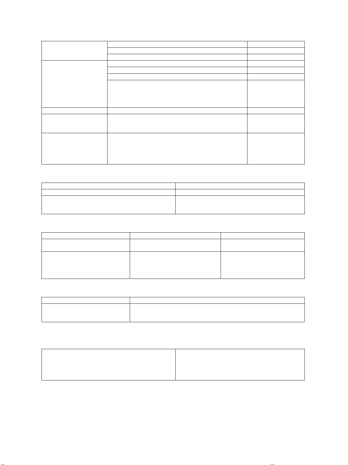
3. Relationship between heat roller surface temperature and fuser lamp operation.
(AR-650)
Temperature
Less than 200°C ON
200°C
More than 200°C OFF
Heater lamp state
Maintains previous status
(AR-800)
Temperature Fusing control
200°C or above Heater lamp OFF
170~200°C
160~170°C Copying is continued at a
160°C or below
Heater lamp ON
Normal copy speed
lower speed.
Copying is interrupted and
the machine is reset to the
ready state.
Heat roller
temperature
distribution
Warm-up Standby (200°C)
C
200
Heater lamp
ON
Warm up Standby(200 )
˚C
200
170
160
Heater lamp
Copy speed
OFF OFF
OFF
ON
0 0 0 80 65 80 65 0 80 65 0
Copying (200°C)
ON
Standby
(200 )
ON
OFF
Copying
ON
ON ON ON ON
ON ON ON ONON ON
OFF
OFF
Copying
OFF
OFF
Waiting
ON
4. Temperature control at heat roller ends
During multicopying, the temperature at each end (no paper-contact area) of the heat roller normally tends
to rise higher than the controlled temperature of the paper-contact area. Therefore, the circuit is designed so
that if the temperature in the no paper-contact area rises to 240°C, the second thermistor detects this,
causing the heater to be turned OFF immediately regardless of the temperature in the paper-contact area.
14 - 1 FUSER UNIT
Page 20

PERIODICAL MAINTENANCE (AR-800)
Inspection every 440,000 Copies
(1) Preparation
Ask the copier operator about the present machine conditions and note them down.
1
Before starting the maintenance work, make and retain a few sample copies for comparison
2
reference purposes.
3
Turn the power switch OFF and disconnect the power cord plug.
(2) The periodic inspection should be conducted in accordance with the Periodic Inspection Check list
shown below.
Perform the inspection by referring to the figures, as well as to the explanation in the Service Manual
when necessary.
(3) After the inspection has been completed, plug in the machine and turn the power switch ON, and
check the general operation of the machine by making a few copies and comparing them to those
made previously.
Inspection and Overhaul every 880,000 Copies
(1) Replace all the consumables.
(2) Check that if there is any damage to the parts in the driving section (gear, pulley, timing belt, etc.). In
principle, replace those parts at this time.
(3) Check to see if there is any damage or peeling of adhered parts (tape, Mylar sheet, etc.). Replace
any affected parts if necessary.
(4) Check that if all the switches and sensors operate properly. Replace them if they are not operating
properly.
(5) Clean the inside of the machine thoroughly.
Note: Before inspecting and overhauling the feed section of the 3-cassette feed unit, remove the
PFP upper aligning unit and PFP feed unit from the copier.
Explanation of the items in the “Remarks” column of the Periodic Inspection Check List
Periodic Inspection Check List
Symbols used in the Periodic Inspection Check List
Cleaning Lubrication Replacement Operation check Date
A
:Cleaning with alcoholL:Launa 40 110: Every 110,000 copies :Check for User’s
:Cleaning with soft Application 440: Every 440,000 copies abnormalities name
pad, cloth, or cleanerSI:Silicon Oil Same from here on after cleaning Machine
(vacuum cleaner)
MAINTENANCE
W
:White grease :
(Molycoat)
AV
:Alvania No.2
Replace in event of deformation or other damage
or No.
replacement. Inspector
Remarks
Page 21

PERIODIC INSPECTION CHECK LIST
Category Item to check
1. Overall unit
2. Main blade 440
3. Toner bag 110
Cleaner
4. Recovery blade
5. Separation claw (for Drum) 440
6. Fur brush 440
7. Toner transport auger drive
8. Cleaner lower guide
8-1.
Toner adhesion amount sensor
8-2. Drum shaft bearing
9. Discharge LED
10. Drum shaft
Drum 11. Drum 440
12. Ozone filter (for exit fan) 440
13. Glass or
14. Glass holder or
15. Mirror 1
16. Mirror 2
17. Mirror 3
Scanner
18. Reflector
19. Lens
20. Exposure lamp
21. Copy area indicator
21-1. Shading glass
22. Automatic paper-size detector
23. Slide sheet (front, rear) or
24. Air filter
25. Case
26. Charger wire 440
Clean at Lubricate at Replace Check
440,000 copies 440,000 copies
W
A
A
A
x 1,000 while on
Charger
Around 30. Slit glass on the copier
laser unit
Developer
Note:
27. Terminal contact
28. Charger wire cleaner 440
29. Grid 440
31. Overall unit
31-1. Duct cover
32. Developer material 440
33. Front shield
The “Remarks” column indicates page and item numbers in the Parts List for consumab parts.
The consumable replacement cycle on the feeding system is the number of sheets fed on each feeding
source.
MAINTENANCE
Page 22

Category Item to check
Clean at Lubricate at Replace Check
440,000 copies 440,000 copies
x 1,000 while on
34. Oil seal (9 portions)
35. Guide roller or
Developer 36. Duct filter
37. Toner filter 440
38. Toner hopper drive worm gear
42. Aligning roller
43. Paper guide
Paper 44. Brush
feed 46. Paper feed system drive gears
section (tooth faces)
47. Aligning unit support bush
and pressurizing leaf spring
69. Upper heat roller (Teflon roller) 440
70. Lower heat roller (rubber roller) 440
71. Upper separation claw 440
72. Lower separation claw
73. Cleaning roller 1 440
74. Cleaning roller 2 440
Fuser unit 75. Cleaning roller 3 440
A
A
AV
W
W
W
75-1. Cleaning roller 4 440
76. Upper and lower thermistors
77. Heat roller entrance guide
78. Heat roller exit guide
79. Paper dust recovery bracket
80. Exit roller
81. Heat roller/cleaning roller drive
gear
82. Cleaning roller bush
83. Transfer belt 440
84. Transfer belt power supply 440
roller
85. Transfer belt cleaning brush 440
Transfer 86. Transfer belt drive roller
belt 87. Transfer belt follower roller
88. Transfer belt separation
auxiliary roller
89-1. Transfer belt cleaning blade 440
89-2. Flicker periphery
89-3. GCB bush and plastic bush
A
A
A
A
SI
SI
A
A
A
L
MAINTENANCE
Page 23

Category Item to check
Clean at Lubricate at Replace Check
440,000 copies 440,000 copies
x 1,000 while on
Transfer 89-4.
belt
ADU 94. ADU aligning roller
PFP 52. Paper guide
ADF 103. ADF reversal roller
Transfer belt separation
auxiliary roller bearing and GCB
90. ADU pick-up roller
91. ADU feed roller
92. ADU separation belt
93. Transport rollers 1 to 4
95. GCB bush and plastic bush
96. Drive gear tooth faces
97.
Exit/ADU switching gate and Main
unit eixt section/ADU relay roller
48. PFP pick-up roller 110
49. PFP feed roller 110
50. PFP separation roller
51. PFP aligning roller
53. Tray drive worm wheel and
gear (tooth faces)
54. PFP drive gear (tooth faces)
55. GCB bush and plastic bush
98. ADF pick-up roller 440
99. ADF feed roller 440
100. ADF separation pad 440
101. Transport belt 440
102. ADF aligning roller
104. ADF empty sensor
105. ADF aligning sensor
106. ADF size sensor
107. Exit sensor
108. ADF timing sensor
109. Transport belt cleaning brush
56. LCF pick-up roller 440
57. LCF feed roller 440
A
A
A
L
A
A
A
L
W
A
AV
110
A
W
W
L
A
A
LCF
58. LCF separation roller
59. Manual pick-up roller 110
60. Manual feed roller 110
61. Manual separation roller
62. Paper guide
63.
Paper feed system drive gears
64. GCB bush and plastic bush
65. Gear
66. Worm and worm wheel
67. Worm shaft
68. Wire pulley shaft
AV
AV
W
L
W
W
W
W
440
110
Note: When lubricating, do not allow oil to come in contact the rollers, belts and belt pulleys.
MAINTENANCE
Page 24

Page 25

SHARP CORPORATION
Digital Document Systems Group
Products Quality Assurance Department
Yamatokoriyama, Nara 639-1186, Japan
2001 November Printed in Japan N
COPYRIGHT © 2001 BY SHARP CORPORATION
All rights reserved.
Printed in Japan.
No part of this publication may be reproduced,
stored in a retrieval system, or transmitted,
in any form or by any means,
electronic, mechanical, photocopying, recording, or otherwise,
without prior written permission of the publisher.
 Loading...