

Page 1
SERVICE HANDBOOK
CODE : 00ZAR650//H1E
DIGITAL COPIER
MODEL
CONTENTS
[ 1 ] ADJUSTMENT . . . . . . . . . . . . . . . . . . . . . . . . . . . . . . . . . . . . . 1 - 1
[ 2 ] PERIODICAL MAINTENANCE . . . . . . . . . . . . . . . . . . . . . . . . . 2 - 1
[ 3 ] PRECAUTIONS FOR STRONG AND HANDLING SUPPLIES . . 3 - 1
[ 4 ] TROUBLESHOOTING . . . . . . . . . . . . . . . . . . . . . . . . . . . . . . . 4 - 1
[ 5 ] INSTALLATION INSTRUCTIONS
FOR FIRMWARE UPDATE THROUGH PC . . . . . . . . . . . . . . . 5 - 1
[ 6 ] MANUAL FOR FIRMWARE DOWNLOAD. . . . . . . . . . . . . . . . . 6 - 1
[ 7 ] HARNESS WIRING DIAGRAMS. . . . . . . . . . . . . . . . . . . . . . . . 7 - 1
Parts marked with “ “ are important for maintaining the safety of the set.
Be sure to replace these parts with specified ones for maintaining the safety and performance of the set.
AR-650
SHARP CORPORATION
This document has been publi shed to be used for
after sales service only.
The contents are subject to change without notice.
Page 2

GENERAL PRECAUTIONS REGARDING THE INSTALLATION
AND SERVICE FOR THE COPIER
The installation and service should be done by a qualified service technician.
1. Transportation/Installation
• When transporting/installing the copier, move it by the casters while lifting the stoppers.
The copier is quite heavy and weighs approximately 250 kg (551 lb), therefore pay full attention
when handling it.
• Be sure to use a dedicated outlet with AC 115V or 120V/20A (220V, 230V, 240V/10A) or more for
its power source.
• The copier must be grounded for safety.
Never ground it to a gas pipe or a water pipe.
• Select a suitable place for installation.
Avoid excessive heat, high humidity, dust, vibration and direct sunlight.
• Also provide proper ventilation as the copier emits a slight amount of ozone.
• To insure adequate working space for the copying operation, keep a minimum clearance of
80 cm (32”) on the left, 80 cm (32”) on the right and 10 cm (4”) in the rear.
2. Service of Machines
• Basically, be sure to turn the main switch off and unplug the power cord during service.
• Be sure not to touch high-temperature sections such as the exposure lamp, the fuser unit, the
damp heater and their periphery.
• Be sure not to touch high-voltage sections such as the chargers, the transfer belt and the highvoltage transformer.
• Be sure not to touch rotating/operating sections such as gears, belts, pulleys, fan, etc.
• When servicing the machines with the main switch turned on, be sure not to touch live sections
and rotating/operating sections. Avoid exposure to laser radiation.
• Use suitable measuring instruments and tools.
• Avoid exposure to laser radiation during servicing.
− Avoid direct exposure to beam.
− Do not insert tools, parts, etc. that are reflective into the path of the laser beam.
− Remove all watches, rings, bracelets, etc. that are reflective.
3. Main Service Parts for Safety
• The breaker, door switch, fuse, thermostat, thermofuse, thermistor, etc. are particularly important for safety. Be sure to handle/install them properly.
4. Cautionary Labels
• During servicing, be sure to check the rating plate and the cautionary labels such as “Unplug the
power cord during service”, “Hot area”, “Laser warning label” etc. to see if there is any dirt on
their surface and whether they are properly stuck to the copier.
Page 3

5. Disposition of Consumable Parts/Packing Materials
• Regarding the recovery and disposal of the copier, supplies, consumable parts and packing
materials, it is recommended to follow the relevant local regulations or rules.
6. When parts are disassembled, reassembly is basically the reverse of disassembly unless
otherwise noted in this manual or other related documents. Be careful not to reassemble
small parts such as screws, washers, pins, E-rings, toothed washers in the wrong places.
7. Basically, the machine should not be operated with any parts removed or disassembled.
8. Precautions Against Static Electricity
• The PC board must be stored in an anti-electrostatic bag and handled carefully using a wristband, because the ICs on it may become damaged due to static electricity.
Caution: Before using the wrist band, pull out the power cord plug of the copier and make
sure that there is no uninsulated charged objects in the vicinity.
Caution : Dispose of used RAM-IC’s (including lithium battery)
according to the manufacturer’s instructions.
Vorsicht : Entsorgung des gebrauchten RAM-IC’s (inklusive
der Lithium Batterie) nach Angaben des Herstellers.
Page 4

1. ADJUSTMENT
2. PERIODICAL MAINTENANCE
3. PRECAUTIONS FOR STORING
& HANDLING SUPPLIES
4. TROUBLESHOOTING
5. INSTALLATION INSTRUCTIONS
FOR FIRMWARE UPDATE
THROUGH PC
6. MANUAL FOR FIRMWARE
DOWNLOAD
7. HARNESS WIRING DIAGRAMS
Page 5

CONTENTS
1. ADJUSTMENT ...................................................................................................................... 1-1
1.1 Error Codes ............................................................................................................................ 1-1
1.2 Self-Diagnostic Modes ........................................................................................................... 1-6
1.2.1 Input signal check (test mode 03) ..................................................................................... 1-8
1.2.2 Output signal check (test mode 03) .................................................................................. 1-10
1.2.3 Test print mode (test mode 04) ......................................................................................... 1-13
1.2.4 Adjustment mode (05) ...................................................................................................... 1-14
1.2.5 Setting mode (08) ............................................................................................................. 1-25
1.2.6 How to register/change ID codes (access control mode) ................................................. 1-33
1.3 Formatting the Hard Disk ....................................................................................................... 1-34
1.4 Auto-Toner Sensor Adjustment .............................................................................................. 1-35
1.5 Print Image Adjustment ......................................................................................................... 1-37
1.5.1 Adjustment of paper aligning value ................................................................................... 1-39
1.5.2 Adjusting the printer section ............................................................................................. 1-40
1.5.3 Adjusting the scanner section ........................................................................................... 1-46
1.6 Image Density ........................................................................................................................ 1-52
1.7 Automatic Adjustment of Gamma correction ......................................................................... 1-53
1.8 Sharpness (HPF) Adjustment ................................................................................................ 1-55
1.9 Data Correction ...................................................................................................................... 1-56
1.10 High-Voltage Adjustment ....................................................................................................... 1-57
1.11 Installation of Carriage Drive Wire ......................................................................................... 1-62
1.11.1 Wire tension adjustment ................................................................................................... 1-62
1.11.2 Adjustment of carriage 1 and carriage 2........................................................................... 1-62
1.11.3 Carriage drive wire assembling ......................................................................................... 1-63
1.12 Lens Unit ................................................................................................................................ 1-65
1.12.1 Adjusting the lens magnification ....................................................................................... 1-66
1.13 Adjusting Horizontal Deviation Caused by Paper Feed ......................................................... 1-68
1.14 Changing the Paper Size ....................................................................................................... 1-69
1.14.1 LCF paper sizes ................................................................................................................ 1-69
1.14.2 PFP paper sizes ............................................................................................................... 1-70
1.15 Adjustment of Duplexer.......................................................................................................... 1-71
1.15.1 Adjustment of the Stack Guide Unit .................................................................................. 1-71
1.15.2 Holding gate position adjustment...................................................................................... 1-73
1.16 Adjusting the Thickness of the Magnetic Brush (leveler) ....................................................... 1-76
1.17 Adjusting the Gap between the Drum and Sleeve ................................................................. 1-76
1.18 Adjustment of Developer Polarity Position ............................................................................. 1-76
1.19 Adjusting the Heat Roller Pressure ........................................................................................ 1-76
1.20 Setting the Heat Roller Temperature and Heat Roller Pressure ............................................ 1-77
1.21 Adjusting the Fuser Inlet Guide.............................................................................................. 1-79
CONTENTS I
Page 6

1.22 Adjustment of ADF ................................................................................................................. 1-80
1.22.1 Adjustment of skew with ADF ........................................................................................... 1-80
1.22.2 Adjustment of ADF horizontal deviation caused for ADF .................................................. 1-81
1.22.3 Adjustment of ADF leading-edge position ........................................................................ 1-82
1.22.4 Adjustment of leading-edge position for ADF (at the Time of Reversing) ......................... 1-82
1.22.5 Adjustment of magnetic catches installation..................................................................... 1-83
1.22.6 Adjustment of the separation area .................................................................................... 1-84
1.22.7 EEPROM Initialization, Sensor Adjustment and Test Mode .............................................. 1-85
1.23 Fine Adjustment of Binding Position/Folding Position ............................................................ 1-86
1.24 Adjustment of RADF Height ................................................................................................... 1-87
1.25 Flapper Solenoid Adjustment ................................................................................................. 1-88
1.26 Additional Parts when Installing the Paper Exit Tray .............................................................. 1-89
2. PERIODICAL MAINTENANCE ............................................................................................. 2-1
2.1 Inspection every 400,000 Copies ........................................................................................... 2-1
2.2
Inspection and Overhaul every 800,000 Copies ....................................................................................
2-1
2.3 Periodic Inspection Check List ...............................................................................................2-1
2.4 Periodical Maintenance Kit (For 400k) ................................................................................... 2-14
2.5 Jig List .................................................................................................................................... 2-15
3. PRECAUTIONS FOR STORING AND HANDLING SUPPLIES............................................ 3-1
3.1 Precautions for Storing Supplies ............................................................................................ 3-1
3.2 Checking and Cleaning the OPC Drum ................................................................................. 3-1
3.3 Checking and Cleaning the Drum Cleaning Blade, Transfer Belt Cleaning Blade ................. 3-2
3.4 Checking and Cleaning the Heat Roller Cleaning Roller 1, 2, 3, 4 ........................................ 3-3
3.5 Checking and Cleaning the Upper and Lower Heat Rollers................................................... 3-3
3.6 Checking and Replacing Transfer Belt ................................................................................... 3-4
3.7 Checking and Replacing Transfer Belt Power Supply Roller.................................................. 3-4
3.8 Checking and Replacing Transfer Belt Cleaning Brush.......................................................... 3-4
3.9 Replacement of maintanance parts ....................................................................................... 3-5
4. TROUBLESHOOTING........................................................................................................... 4-1
4.1 Scanner System Related Service Call ................................................................................... 4-1
4.2 Process System Related Service Call ................................................................................... 4-3
4.3 Fuser Related Service Call .................................................................................................... 4-4
4.4 Communication Related Service Call .................................................................................... 4-6
4.5 ADF Related Service Call ...................................................................................................... 4-7
4.6 Other Troubles on the ADF System........................................................................................ 4-8
4.7 Other Service Calls ................................................................................................................ 4-12
4.8 Laser Optical system Related Service Call ............................................................................ 4-13
4.9 Finisher Related Service Call ................................................................................................. 4-15
4.10 Image Quality Maintenance Control Related Troubleshooting ............................................... 4-30
II CONTENTS
Page 7

5. INSTALLATION INSTRUCTIONS FOR FIRMWARE UPDATE THROUGH PC .................... 5-1
5.1 Outline .................................................................................................................................... 5-1
5.2 System Configuration ............................................................................................................. 5-1
5.3 Preparation of PC to use a network ....................................................................................... 5-2
5.3.1 Setting Virtual Modem ......................................................................................................... 5-2
5.3.2 Using Dial-Up Networking ...................................................................................................5-6
5.3.3 Using New Connection ........................................................................................................ 5-8
5.4 Installation of FTP Server ...................................................................................................... 5-12
6. MANUAL FOR FIRMWARE DOWNLOAD ............................................................................ 6-1
[ 3 ] [ 9 ] Mode operation ........................................................................................................ 6-1
6.1 Outline .................................................................................................................................... 6-1
6.2 Preparation of PC .................................................................................................................. 6-1
6.2.1 Software Installation ............................................................................................................ 6-1
6.2.2 Preparation of Updated Files...............................................................................................6-2
6.2.3 Connection between Copier and PC ................................................................................... 6-3
6.3 Download Operation .............................................................................................................. 6-4
6.4 Screen Details ........................................................................................................................ 6-10
7. HARNESS WIRING DIAGRAMS ........................................................................................... 7-1
7.1 AC Wire Harness ................................................................................................................... 7-1
7.2 DC Wire Harness ........................................................................................................... Appendix
CONTENTS III
Page 8

1. ADJUSTMENT
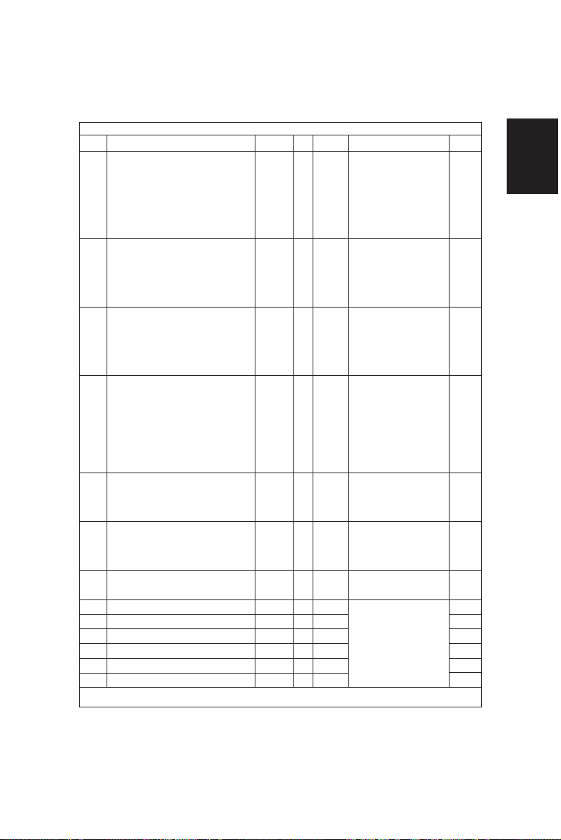
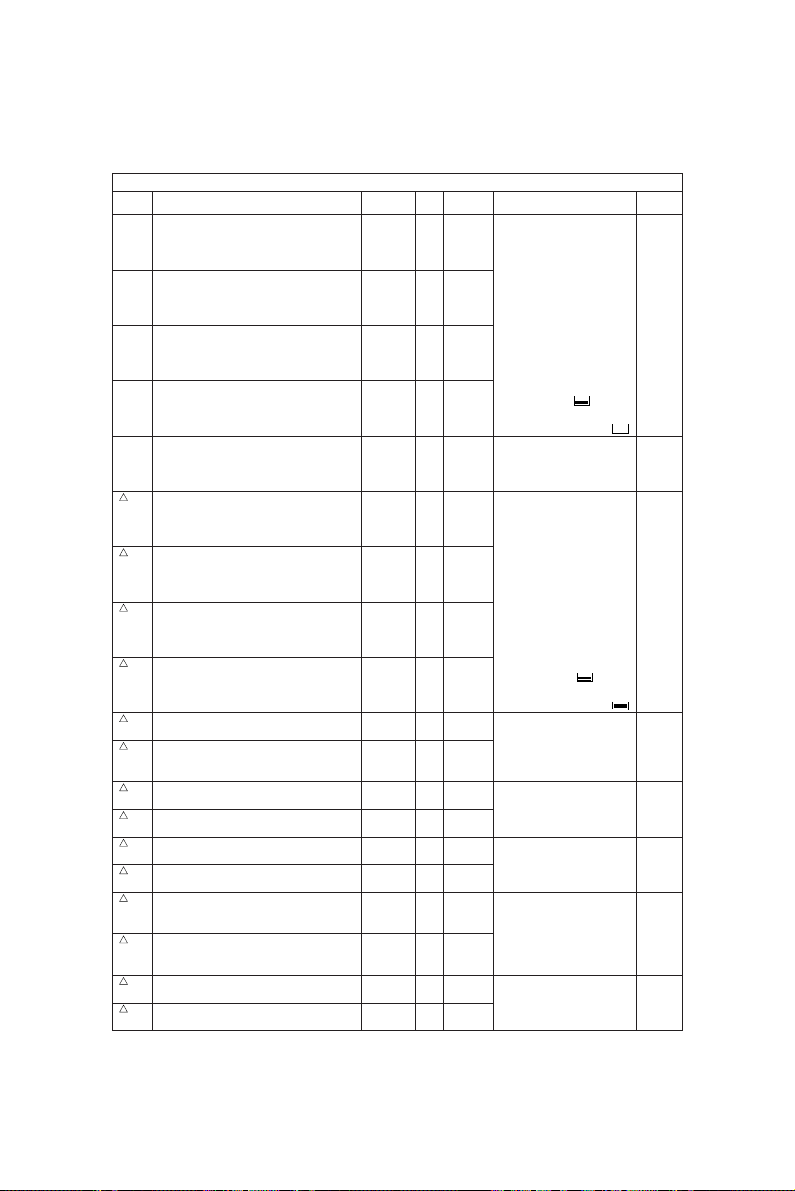
1.1 Error Codes
When either the CLEAR PAPER ( ) or CALL FOR SERVICE ( ) symbol appears, press the CLEAR/STOP
and [8] keys simultaneously and the corresponding error code will be displayed.
/ → [C] + [8] (error code)
Group
Transporting jam inside the
copier 1
Paper feeding jam
Transport jam from feed for
RGT
Paper jam if some cover is
opened during copying
ADU reversal section
transport line jam
Original transporting jam
at the ADF
Paper jam at the finisher
Error code
Fuser exit switch non-arrival jam
E01
Fuser exit switch accumulation jam
E02
Paper remaining inside the copier at power ON
E03
Jam caused by HDD error
E09
Image transport ready timeout
E0A
(Image data transport error between SYS board and PLG board)
Bypass feeding jam
E12
PFP 1st cassette feeding jam
E15
PFP 2nd cassette feeding jam
E16
PFP 3rd cassette feeding jam
E17
LCF feeding jam
E19
PFP transport jam (non-arrival at RGT)
E31
E31:During upper cassette feed
E32:During middle cassette feed
E32
E33:During lower cassette feed
E33
PFP transport jam (inside the PFP)
E34
E34:During upper cassette feed
E35:During middle cassette feed
E35
E36:During lower cassette feed
E36
Copier front cover is opened during copying
E41
Exit jam processing cover is opened during copying
E47
ADU RGT non-arrival
E50
ADU transport TR1 non-arrival
E51
ADU transport TR2 non-arrival
E52
PFP upper cassette RGT non-arrival (from ADU feed)
E53
ADU feed non-arrival
E54
Paper on transport path at copy end
E55
Paper on PFP transport path after door open/close
E56
Reversal switch non-arrival jam
E57
Reversal switch accumulation jam
E58
Exit switch accumulation jam
E59
Exit switch non-arrival jam
E5A
ADU transport start timeout jam
E5B
Original feeding jam at the feed section of the ADF
E71
Original transporting jam at the transport section of the ADF
E72
Original exiting jam at the exit section of the ADF
E73
PUNCH jam
E9F
Transporting delay jam
EA1
Transporting stationary jam
EA2
Jam at power ON
EA3
Door open jam
EA4
Staple jam
EA5
Early arrival jam
EA6
Machine status
Reference
1 - 1 ADJUSTMENT
Page 9
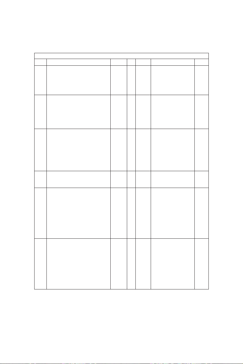
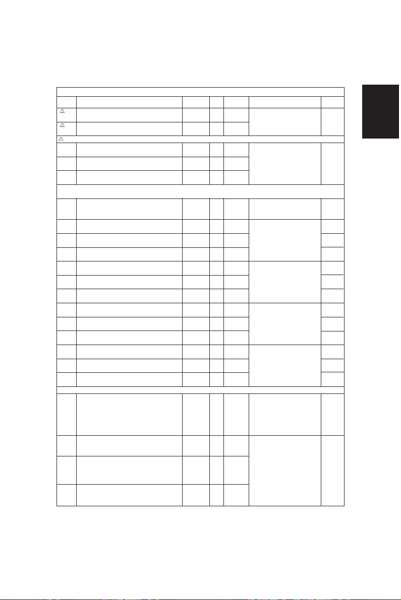
Group
Paper jam at the finisher
Copier transport jam 2
Paper feeding error
(Refer to page 1-4)
Service call from the
optical system
Process system related
service call 1
Process system related
service call 2
Fuser related
Service call from
communication
Service call ADF
Error code
EA8
Finisher saddle staple jam
EA9
Finisher saddle door open jam
EAA
Finisher saddle power ON jam
EAB
Finisher saddle transport accumulation jam
EAC
Finisher saddle transport delay jam
EAD
Print end command time-out jam
EAE
Finisher receive time-out jam
Machine status
Paper cannot be detected from the copier in a fixed-time.
Finisher ready time-out error
EB3
(Finisher cannot prepare for receiving the paper after the
leading edge of the paper reaches to RGT in a fixed-time.)
Double jam
EB5
(Residence jam occurs because of the double paper is
EB6
separated in paper feeding.)
Duplexer side guide is abnormal
C11
Duplexer stopper guide is abnormal
C12
PFP upper tray is abnormal
C15
PFP middle tray is abnormal
C16
PFP lower tray is abnormal
C17
LCF tray is abnormal
C18
Peak detection error
C26
Home switch does not turn OFF
C27
Home switch does not turn ON
C28
Scanner disconnection detection
C29
Charger cleaning operation error
C36
Transfer belt operation error
C37
Drum thermistor disconnection
C42
Brush motor lock error
CD1
Auger motor lock error
CD2
Abnormal thermistor or heater disconnection at power ON
C41
Warming up mode after disconnection judgment, or abnormal
C43
thermistor after ready
Warm-up time after detected disconnection or heater discon-
C44
nection after ready
Thermistor disconnection at HTR edge portion
C45
Lower thermistor (press roller) error after ready (Low temperature
C46
is detected because of disconnection or connector omission.)
Communication error between PFC and MCPU
C56
C57
Communication error between MCPU and IPC
C58
Communication error between IPC and the finisher
C59
Communications error between MCPU and LCPU
F07
Communications error between SYS and LGC boards
F11
Communications error between SYS and SLG boards
C72
Defective adjustment by the aligning sensor detected
C73
EEPROM defective initialization
C74
Defective adjustment by the exit/reversal sensor detected
C76
Transmission time-out error
C77
Transmission buffer full
C78
ADF power ON I/F error
C79
Reception time-out error
C80
Defective adjustment of ADF timing sensor
C93
ADF original stop signal not received
Reference
4.1
4.1
4.1
4.1
4.2
4.2
4.2
4.7
4.7
4.3
4.3
4.3
4.3
4.3
4.4
4.4
4.4
4.4
4.4
4.4
4.5
4.5
4.5
4.5
ADJUSTMENT 1 - 2
Page 10
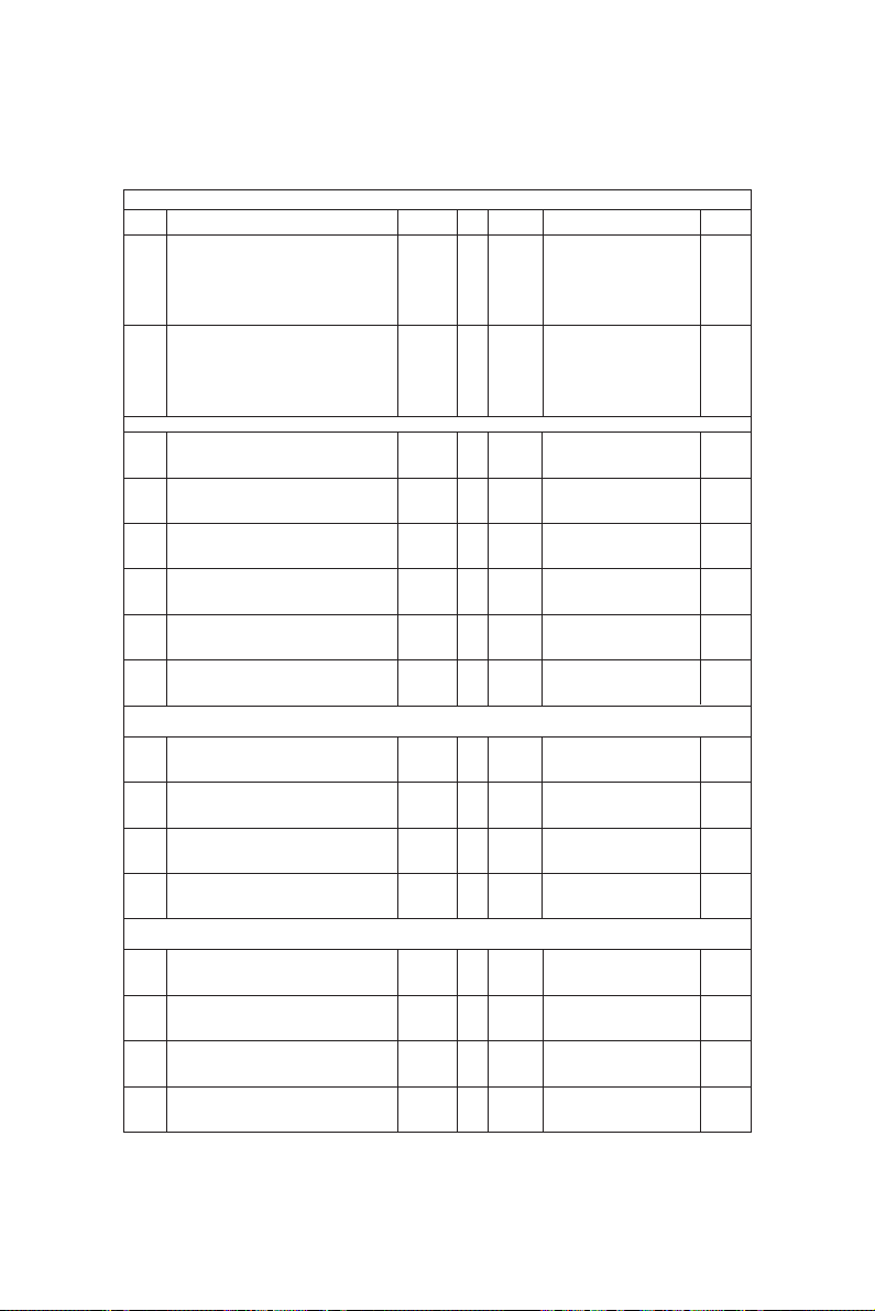
Group
Other service calls
Service call from the
laser optical
Service call from the finisher
Finisher related service call
Service call from the others
Error code
C94
M-CPU is abnormal
C99
PFC microcomputer is abnormal
CA1
Polygonal motor is abnormal
CA2
HSYNC is abnormal
CA3
Secondary scanning rough adjustment error
CA4
Primary scanning counter load error
CA5
Laser power adjustment error
CA6
Laser PWM calibration error
CA9
Image data transfer malfunction from SYS board
CAA
Secondary scanning fine adjustment error
CAB
Secondary scanning inter-page compensation error
CAC
Primary scanning dot adjustment error
CAD
Primary scanning tap adjustment error
CAE
Primary scanning tap amount measurement error
CAF
Primary scanning inter-page compensation error
CD0
Laser initialize time-out error
CB1
Transport motor is abnormal
CB2
Exit motor is abnormal
CB3
Tray elevation motor is abnormal
CB4
Alignment motor is abnormal
CB5
Staple motor is abnormal
CB6
Staple unit shift motor is abnormal
CB7
Stacking sensor is abnormal
CB8
Backup RAM data is abnormal
CB9
Saddle thrust motor is abnormal
CBA
Saddle front staple motor is abnormal
CBB
Saddle inner staple motor is abnormal
CBC
Saddle alignment motor is abnormal
CBD
Saddle guide motor is abnormal
Saddle fold motor is abnormal
CBE
Saddle positioning plate motor is abnormal
CBF
Sensor connector connection error
CC0
Microswitch error
CC1
Communications error between finisher saddle
CC2
Swing motor is abnormal
CC4
Horizontal registration motor is abnormal
CC5
Punch motor is abnormal
CC6
Power abnormality interrupt error
C92
C94
MCPU is abnormal
C99
PFC microcomputer is abnormal
F10
HDD formatting error
Machine status
Reference
4.8
4.8
4.8
4.8
4.8
4.8
4.8
4.8
4.8
4.8
4.8
4.8
4.8
4.8
4.8
4.8
4.9
4.9
4.9
4.9
4.9
4.9
4.9
4.9
4.9
4.9
4.9
4.9
4.9
4.9
4.9
4.7
4.7
4.7
4.7
1 - 3 ADJUSTMENT
Page 11

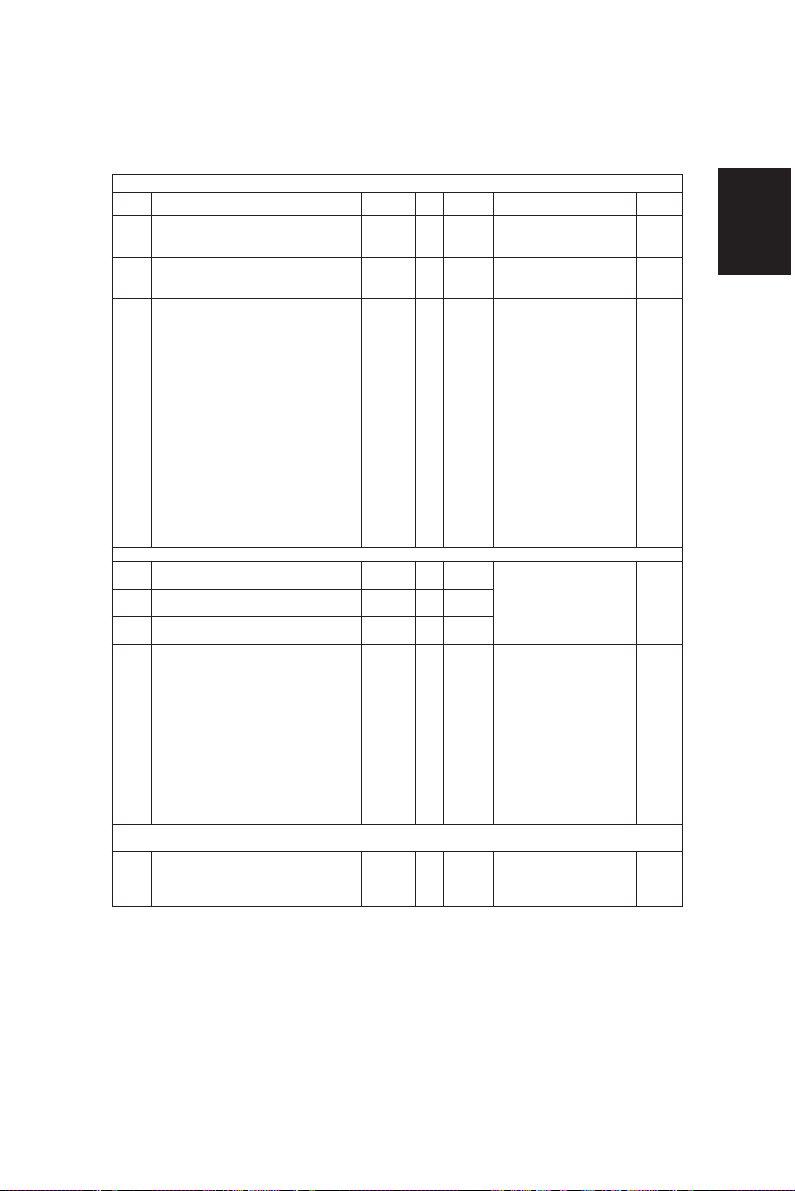
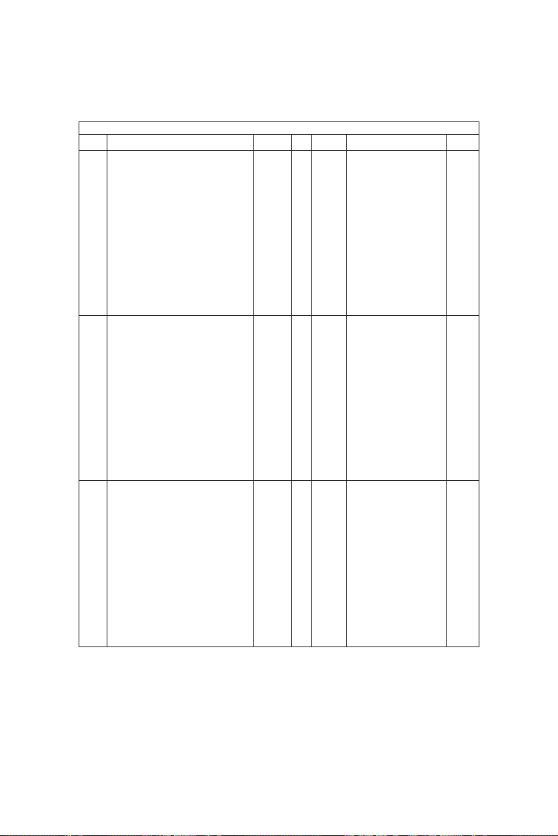
Addition to the explanation
(1) When a paper feeding error occurs:
: Error has occurred in the unit →Disabled
: No error has occurred in the unit →Enabled
: To operate continuously, error code ([C]+[8]) is not displayed.
(2) During C11 and C12 error codes
* If the mode which Duplexer is used is selected as “single-sided → duplex” or “two-sided → duplex”,
the “install the Duplexer” message is displayed and printing is not possible.
* If the mode other than the above (the Duplexer is not used) is selected, the operation can be
normally accepted.
(3) During C15, 16, 17 error codes
* If a cassette in which an error has occurred is selected:
The “Add Paper” message is displayed even if the sheet is set, and copying can be performed
when another paper cassette is selected.
* If a cassette other than the above is selected, the operation can be normally accepted.
ADJUSTMENT 1 - 4
Page 12
Error history (08-253)
(Display example)
Copy mode
A Paper feed cassette
0: Non-select 1: Bypass 2: LCF 3: PFP(U) 4: PFP(M) 5: PFP(L) 6: ADU
B Paper size code
0: Non-select 1: A5-R 2: ST-R 3: LT 4: A4 5: B5-R 6: LT-R 7: A4-R 8: OTHER/UNIV 9: B5
A: FOL/COM B: LG C: B4 D: LD E: A3 F: 13'LG G: 8.5*8.5
C Sort mode/Staple mode
0: Non-select 1: Group 2: Sort 7: Staple (Front) 8: Staple (2 places) 9: Staple (Rear) A: Saddle stetch
D DF mode
0: Not used 1: AUTO FEED (SADF) 2: STACK FEED
E APS/AMS mode
0: Non-select 1: APS 2: AMS
F Duplex mode
0: Non-select 1: Book 2: Two-sided/Single-sided 4: Two-sided/Duplexed
8: Single-sided/Duplexed
G Not used
0: Not used
H Image shift
0: Not used 1: Book 2: LEFT 3: RIGHT
I Editing
0: Not used 1: Masking 2: Trimming 3: Mirroring 4: Negative/Positive
J Edge-erase/Dual-page
0: Not used 1: Edge-erase 2: Dual-page 3: Edge-erase & Dual-page
K Not used
0: Not used
L Function
0: Not used 1: PPC 2: Not used 3: Not used 4: GDI 5: DSS
EA1
Error code
3 digit
9 9 0 3 2 6 1 7 5 7 3 2
YYMMDDHHMMSS
12 digit (Date, time)
6 4
MMM
3 digit
(Reproduction ratio)
NNN
3 digit
6 4
2 3 6 2 1 0 0 0 0 0 0 0
ABCDEFGHIJKL
12 digit
(Copy mode)
Reproduction ratio
MMM Primary scanning reproduction ratio (Y direction)
Hexadecimal
NNN Secondary scanning reproduction ratio (X direction)
Hexadecimal
Setting mode, code "253" displays latest 8 error data
1 - 5 ADJUSTMENT
Page 13
1.2 Self-Diagnostic Modes
[
]
This copier is a multi-function copier (net work printer, DSS). So, compared with conventional copiers:
1) It has more setting items in the self-diagnostic mode.
2) Setting items are related to each other.
For this reason, if normal operations are continued on the control panel (by [0] + [9] or [C] keys) when
adjustments are completed, operation trouble (e.g. machine lock) may occur due to the internal structure
of the program.
So, when the self-diagnostic mode in adjustments after unpacking, servicing or preventative maintenance, first turn the power OFF before handing the copier over to the user.
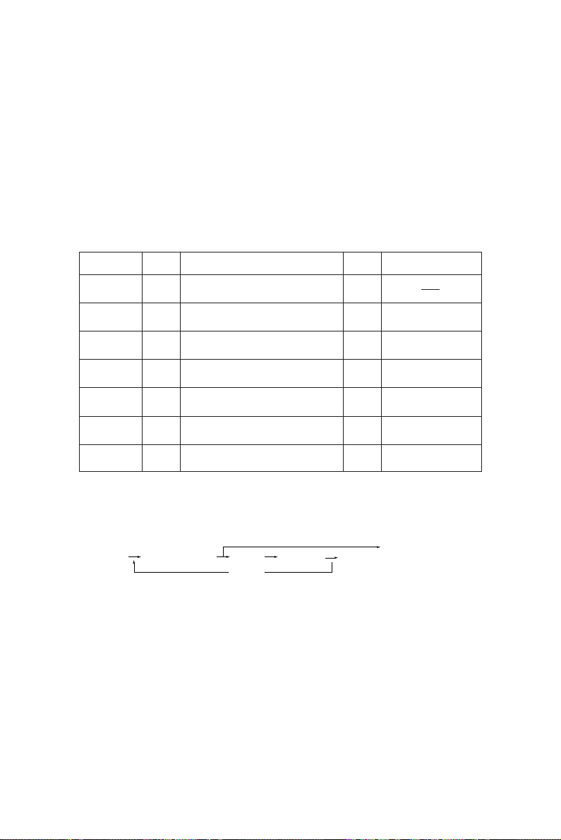
Mode
All-LEDs-lit
Test mode
Test print
mode
Adjustment
mode
Setting mode
List print
mode
Unit replace
mode
Note: To access the desired self-diagnostic mode, turn on the power switch while pressing the appropriate keys
(e.g. [0]+[5]).
Input
code method
[0]+[1]+
All LEDs on the control panel are lit, and all
[PWR]
pixels on the LCD light and go out.
[0]+[3]+
Input/output signals are checked.
[PWR]
[0]+[4]+
Test print
[PWR]
[0]+[5]+
Adjustment of items
[PWR]
[0]+[8]+
System switchover and setting of each
[PWR]
priority mode, PM counter, etc.
[9]+[START]
[6]+[START]
Printing of 05, 08 code data lists
+[PWR]
Mode for executing auto-toner adjustment
+[PWR]
and drum counter clear
Definition
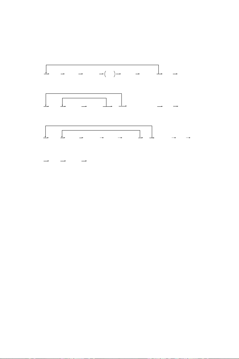
<Procedure>
• All-LEDs-lit mode (01):
[0] [1]
[PWR]
( All LEDs light ) [START]
START
(Key check) [C] Exit
Notes: 1. The mode cannot be cleared by [0]+[9] during the key check; it can be cleared only by [C].
It can be cleared by both [0]+[9] and [C] when all LEDs on the control panel are lit.
2. Key Check With LED (Press to turn LED out.)
Without LED (Press to display this in message area.)
Clearing
[C]or
[0]+[9]
[0]+[9]
[0]+[9]
[0]+[9]
[0]+[9]
[PWR]
OFF
[PWR]
OFF
Display
100% C A4
TEST MODE
100% P A4
TEST PRINT
100% A A4
TEST MODE
100% D A4
TEST MODE
100% P A4
LIST PRINT
100% K A4
TEST MODE
[C] or [0] [9] Exit
ADJUSTMENT 1 - 6
Page 14
• Test mode (03): Refer to 1.2.1 and 1.2.2.
• Test print mode (04): Refer to “1.2.3 Test print mode”.
• Adjustment mode (05): Refer to “1.2.4 Adjustment mode”.
• List print mode
[9] [START]
[PWR]
(code) [START]
101: 05 adjustment code
102: 08 setting code
103: 08 setting code (For tandem)
201: Job access code
(Start of operation)
• Unit replace mode
[PWR] OFF
[6] [START]
[PWR]
(code) [START]
1: Auto-toner adjustment
2: Drum counter reset
(Start of operation)
[PWR] OFF
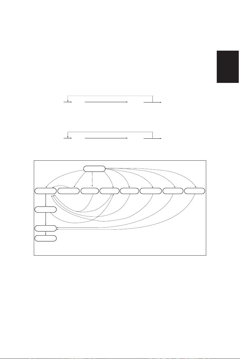
• Setting mode (08): Refer to “1.2.5 Setting mode”.
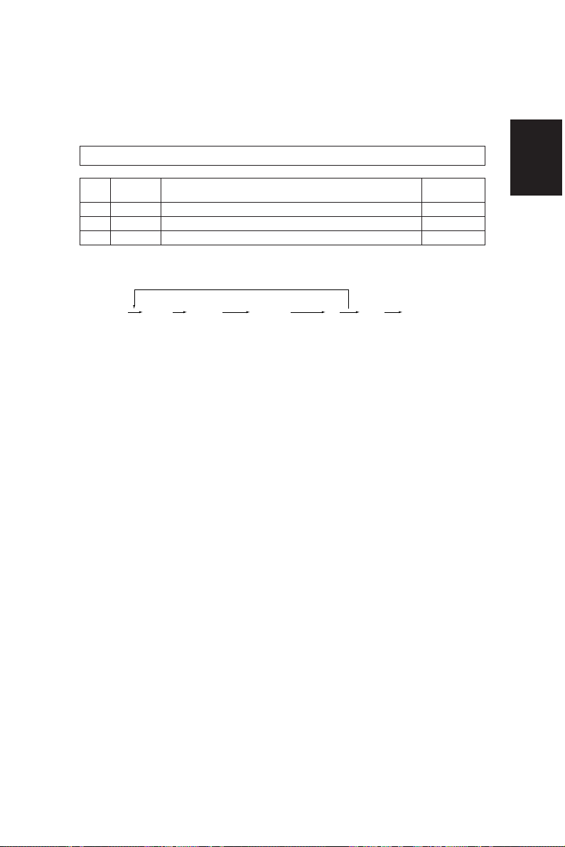
[0][1]
*2
[Power] ON
[0][3] [0][5]
Test mode
[0][8]
Adjustment mode
[0][9][0][9]
[0][4] [9][S] [6][S]
Setting mode
[0][9]
Test print mode
[0][9]
List print mode
[S]: START key ON.
[C]: CLEAR key ON.
Unit replace mode
Warming up
Standby
[Power] OFF
*3
Hand over to user
Normal
[C]
All the displays on
the control panel lit
*1
[0][5]
Quick reference chart for self-diagnostic mode
*1 When the copier is in the adjustment mode which you entered by turning the power switch ON while
pressing keys [0] and [5] simultaneously, pressing keys [0] and [9] simultaneously will set the copier
to the standby mode. In this standby mode only can the adjustment mode be accessed repeatedly
by simply entering [0] and [5].
*2 While all the displays on the control panel are lit, copying is not available. When the copier enters the
standby mode by pressing the [0] [9] or [C], copying is enabled.
*3 When the self-diagnostic mode was used, turn the power OFF, then hand over to the user.
1 - 7 ADJUSTMENT
Page 15
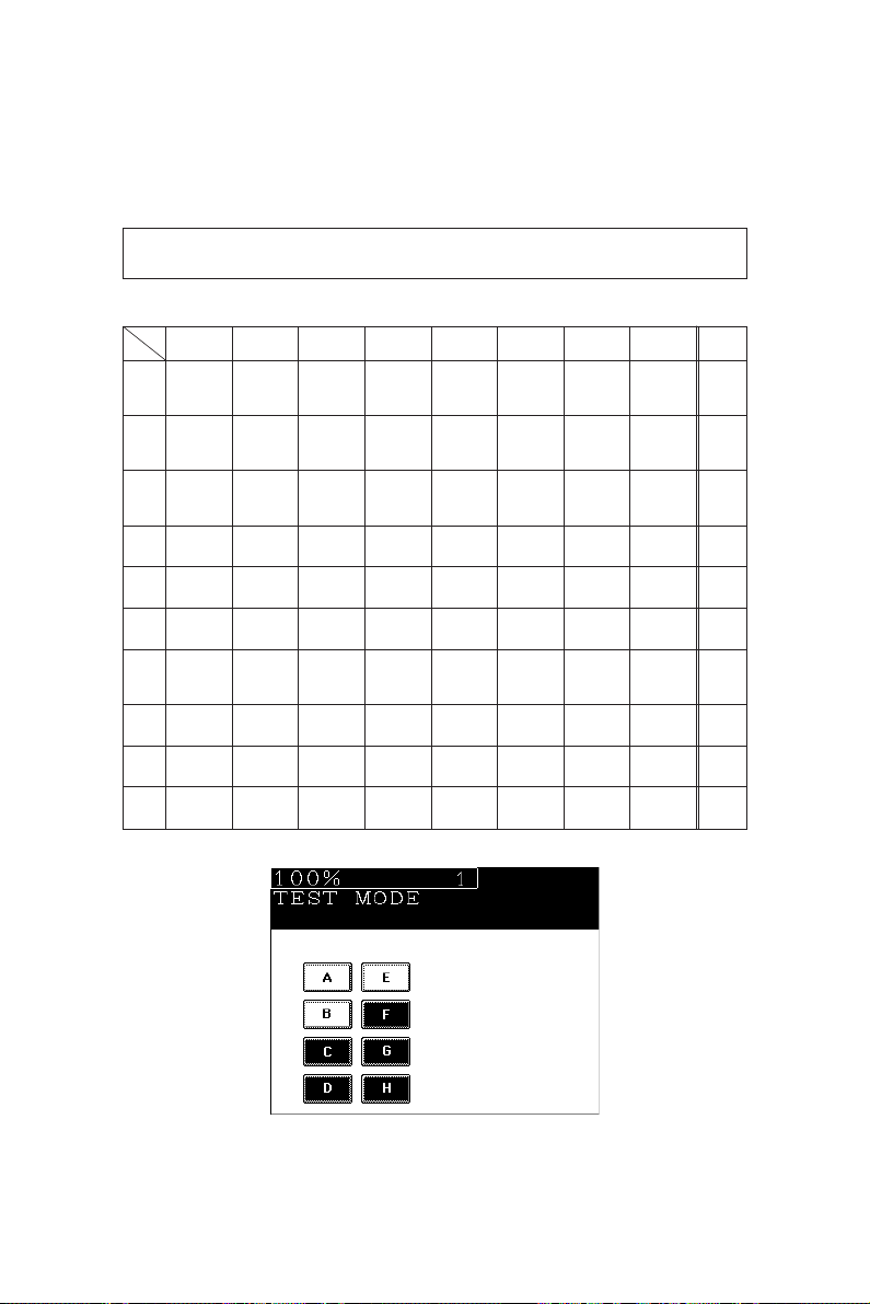
1.2.1 Input signal check (Test mode 03)
In the [0] [3] test mode, the following input signal states can be checked by pressing the corresponding
keys.
[A] When the ENERGY SAVER key is OFF (LED indicating the energy saver mode is out)
Icon
Key
[1]
[2]
[3]
[4]
[5]
[6]
[7]
[8]
[9]
[0]
ABCDEFGH
(OFF)
(OFF)
(ON)
(ON)
–
–
–
–
–
–
Manual feed
paper width
switch 1
(OFF)
Manual feed
switch
(OFF)
ADU side
switch
(ON)
PFP middle
cassette SW
(ON)
–
–
ADU
connection
(Disconnection)
Fuser exit
switch
(OFF)
–
–
Manual feed
paper width
switch 0
ADU empty
switch
(Not empty)
PFP lower
cassette SW
Copier
paper stop
switch
Developer
unit not
mounted SW
LCF bottom
SW
(Bottom)
ADU
transport
switch 2
(ON)
–
PFP-U paper
start SW
(OFF)
PFP-M paper
start SW
(OFF)
PFP-L paper
start
SW
(OFF)
–
Front cover
SW
(OFF)
–
–
LCF door
SW
(Open)
LCF paper
start switch
(OFF)
–
PFP-U
paper
stop SW
(OFF)
PFP-M paper
stop SW
(OFF)
PFP-L
paper
stop SW
(OFF)
–
Reversal
switch
(ON)
–
–
LCF tray up
SW
(Top)
ADU feed
switch
(ON)
–
PFP-U
tray up SW
(ON)
PFP-M
tray up SW
(ON)
PFP-L
tray up SW
(ON)
–
Exit switch
(ON)
–
–
LCF empty
SW
(Not empty)
ADU
transport
switch 1
(ON)
–
PFP-U
empty SW
(OFF)
PFP-M
empty SW
(OFF)
PFP-L empty
SW
(OFF)
–
–
IPC
connection
(Disconnection)
–
Manual feed
paper width
switch 3
(OFF)
LCF switch
(Disconnection)
ADU end
switch
(ON)
–
–
–
–
Toner-full
switch
(ON)
–
–
Manual feed
paper width
switch 2
LCF tray
down key
ADU
aligning
switch
PFP upper
cassette SW
(OFF)
–
(ON)
–
–
(ON)
–
–
Remarks
–
–
–
–
–
–
–
–
–
–
Icons on the control panel in the table states are displayed as white on a black background (ON state).
ADJUSTMENT 1 - 8
Page 16
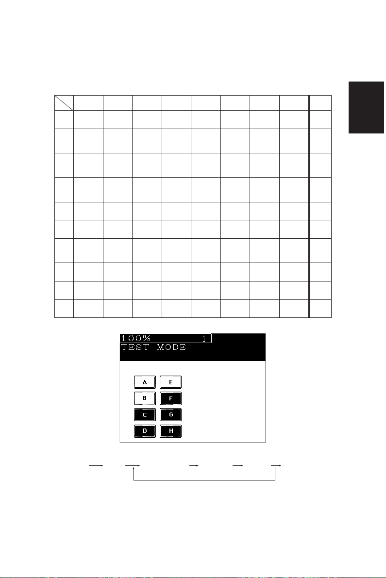
[B] When the ENERGY SAVER key is ON (LED indicating the energy saver mode is lit)
Icon
Key
[1]
[2]
[3]
[4]
[5]
[6]
[7]
[8]
ABCDEFGH
–
–
–
–
Platen
switch
(Close)
–
ADF size
switch 1
(ON)
–
APS
sensor 3
(OFF)
ADF size
switch 2
(ON)
–
–
–
–
–
–
–
Total
counter
connection
(Disconnection)
–
–
–
APS
sensor 2
(OFF)
ADF empty
switch
(OFF)
–
–
Auto toner
sensor
connection
(Disconnection)
–
–
–
APS
sensor 1
(OFF)
ADF cover
(Open)
–
–
–
–
–
–
APS
sensor 6
(OFF)
ADF APS
start SW
(ON)
–
–
Cleaner
connection
(Disconnection)
Key counter
connection
(Disconnection)
–
–
APS
sensor 5
(OFF)
ADF exit
sensor
(ON)
–
–
Main charger
cleaning
switch
(OFF)
Toner supply
cover switch
(Open)
Transfer belt
contact
switch
(OFF)
ADF
connection
(Disconnection)
APS
sensor 4
(OFF)
ADF timing
sensor
(ON)
–
Exit cover
switch
(Open)
Toner empty
switch
(OFF)
Transfer belt
separation
switch
(OFF)
Scanner
home SW
(OFF)
ADF
aligning
sensor
(ON)
–
–
–
Remarks
–
–
–
–
–
–
–
–
[9]
[0]
–
–
–
–
–
–
–
–
–
–
–
–
–
–
–
–
–
–
Icons on the control panel in the table states are displayed as white on a black background (ON state).
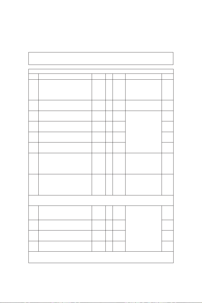
<Procedure>
[0] [3]
[PWR]
[START] [ENERGY SAVER] [Digital keys] (LCD ON) [0] [9]
(Exit)
Note: Initialization is executed before test mode is entered.
1 - 9 ADJUSTMENT
Page 17
1.2.2 Output signal check (test mode 03)
In the [0] [3] test mode, the following output signal states can be checked by entering the corresponding codes.
Code Function Code Function
101 Drum motor ON 151 OFF 1
102 Toner motor ON 152 OFF 1
103 Polygonal motor mirror (600 dpi) ON 153 OFF 1
108 Aligning motor ON 158 OFF 1
109 Pedestal motor ON 159 OFF 1
110 ADU motor ON 160 OFF 1
111 Scraper solenoid ON 161 OFF 1
112 Developer motor ON 162 OFF 1
113 Heat roller motor ON 163 OFF 1
114 Transfer belt motor ON 164 OFF 1
115 Fur brush motor ON 165 OFF 1
116 Auger motor ON 166 OFF 1
117 Laser bias ON 167 OFF 1
118 Laser ON 168 OFF 1
119 Fuser unit motor rotating slowly ON 169 OFF 1
218 Total counter counts 2
219 Reversal fan ON/OFF 3
220 ADU transport clutch ON/OFF 3
221 ADU aligning clutch ON/OFF 3
222 ADU feed clutch ON/OFF 3
223 ADU stack clutch ON/OFF 3
226 PFP upper feed clutch ON/OFF 3
227 PFP middle feed clutch ON/OFF 3
228 PFP lower feed clutch ON/OFF 3
229 PFP upper aligning feed clutch ON/OFF 3
230 PFP middle aligning feed clutch ON/OFF 3
231 PFP lower aligning feed clutch ON/OFF 3
233 Manual feed motor ON/OFF 3
234 Manual feed pick-up solenoid ON/OFF 3
235 Discharge LED lamp ON/OFF 3
236 Exit fan, low speed ON/OFF 3
237 Exit fan, high speed ON/OFF 3
239 Main charger fan ON/OFF 3
240 Developer fan ON/OFF 3
241 Heater fan low-speed ON/OFF 3
242 Heater fan high-speed ON/OFF 3
243 Main charger wire cleaner ON (reset) 2
244 Transfer belt cam motor UP/DOWN 3
249 Developer bias -DC1 ON/OFF 3
Operation
procedure
group
ADJUSTMENT 1 - 10
Page 18

Code Function
250 Developer bias -DC2 ON/OFF 3
251 Developer bias -DC3 ON/OFF 3
252 Main Charger ON/OFF 3
255 Transfer belt cleaning brush bias ON/OFF 3
257 Duct (in/out) fan, low speed ON/OFF 3
259 Duct (in/out) fan, high speed ON/OFF 3
261 Scanning motor ON 2
(Automatically stops at the limit position, its speed is variable using the ZOOM keys.)
262 Document (indicator) motor ON 2
(Automatically stops at the limit position)
263 Exposure lamp ON 3
(Automatically goes OFF after 6 seconds, and the fan motors rotate at low speed.)
264
Scanning optical system cooling fan motor 1
265
Scanning optical system cooling fan motor 2
266 SLG PC board cooling fan motor 3 ON/OFF 3
270 LCF feed motor ON/OFF 3
271 LCF tray motor UP/DOWN 2
272 ADU side guide motor ON (reciprocating) 2
273 ADU end guide motor ON (reciprocating) 2
274 ADU/exit switching gate solenoid ON/OFF 3
275 ADU paper holding gate solenoid ON/OFF 2
277 ADU reverse clutch ON/OFF 3
278 PFP upper tray motor UP/DOWN 2
279 PFP middle tray motor UP/DOWN 2
280 PFP lower tray motor UP/DOWN 2
281 ADF pick-up roller rotation ON/OFF 3
282 ADF aligning roller rotation ON/OFF 3
283 ADF transport belt CW rotation ON/OFF 3
284 ADF transport belt CCW rotation ON/OFF 3
285 ADF reverse roller rotation ON/OFF 3
288 ADF reverse solenoid ON/OFF 3
292 Laser unit fan ON/OFF 3
295 Power off mode 4
ON/OFF 3
ON/OFF 3
Operation
procedure
group
List of System Output Check Functions
Code Function
401 Get mounted PM (page memory) size 2
402 PM (page memory) read/write check 2
1 - 11 ADJUSTMENT
Operation
procedure
group
Page 19
<Procedure>
Group (1)
[START]
(Code) Operation
[PWR]
Group (2)
[0] [3]
(Code) [START] Operation
[PWR]
Group (3)
[0] [3]
(Code) [START] Operation
[PWR]
Group (4)
[0] [3]
(Code) [START] [PWR] OFF
[PWR]
(ON)
(One-way)
(ON)
Stop
[START] Operation
code
[C] Test mode standby
[START] Operation
(OFF)
(OFF)
[C]
[0] [9] Warm-up[0] [3]
[0] [9] Warm-up
Test mode
standby
[0] [9]
Warm-up
ADJUSTMENT 1 - 12
Page 20
1.2.3 Test print mode (test mode 04)
In test mode “04”, you can print the test pattern generated by the following ASIC codes.
Code ASIC Test pattern type
111 SH Primary scanning. 33 gradations, error diffusion
113 SH Secondary scanning. 33 gradations, error diffusion
142 POPS 2 dots grid pattern (10mm Pitch)
Remarks
<Operation procedure>
[PWR]
[START](Code)[0] [4]
(Test print)
[0] [9][C] Warm-upOperation
Note: Though errors are displayed when it occurs, recovery is not carried out. This is recovered by
turning the power OFF then ON again.
1 - 13 ADJUSTMENT
Page 21
1.2.4 Adjustment mode (05)
In this mode, the following adjustment items can be corrected or changed. To access this mode, turn
the power ON while pressing the [0] and [5] keys.
CODE
200 Automatic adjustment of the Auto-toner circuit. All — —
201 Manual adjustment of the Auto-toner circuit. All 128 0-255 2
♦203 Developer High 1 adjustment Printer 104 0-255 1
Out put is NOT available for measurement.
Enter the value set in code 205-0.
♦205-0 Developer High 1 adjustment Copier 104 0-255 7
Output IS available for measurement. (Text/
Adjust by measuring the output. Photo)
♦205-1 Developer High 1 adjustment Copier 104 0-255 6
Output is NOT available for measurement. (Text)
Enter the value set in code 205-0.
♦205-2 Developer High 1 adjustment Copier 104 0-255 6
Output is NOT available for measurement. (Photo)
Enter the value set in code 205-0.
♦207 Developer High 2 adjustment All 104 0-255 2
Out put IS available for measurement.
Adjust by measuring the output.
♦216 Developer High 3 adjustment All 133 0-255 2
Output IS available for measurement.
♦Key in Code 205 press the START key, key in the Sub Code, then press the START key. For 205-0, 207 and 216 use the UP
or DOWN key to change the value, press the SET key to store or the RESET key. For codes 203, 205-1 and 205-2 key in the
value set in code 205-0, press the SET key to store or the CLEAR key to reset.
♣210-0 Charge corona grid voltage adjustment. The Copier 93 0-255 7
developer unit must be removed. (Text/
Output IS available for measurement. Adjust Photo)
by measuring the grid voltage output.
♣210-1 Charge corona grid voltage adjustment. Copier 93 0-255 6
Output is NOT available for measurement. Set (Text)
to the value set in code 210-0.
♣210-2 Charge corona grid voltage adjustment. Copier 93 0-255 6
Output is NOT available for measurement. Set (Photo)
to the value set in code 210-0.
♣212 Charge corona grid voltage adjustment. Printer 93 0-255 1
Output is NOT available for measurement. Set
to the value set in code 210-0.
♣Key in Code 210 press the START key, key in the Sub Code, then press the START key. For 210-0 use the UP or DOWN key
to change the value, press the SET key to store or the RESET key. For codes 210-1, 210-2 and 212 key in the value set in
code 210-0, press the SET key to store or the CLEAR key to reset.
ADJUSMENT MODE
05 MODE
DEFAULT
RANGE DESCRIPTION
Increasing the value increases
the sensor out put.
Output is automatically set in
the range of 2.45 - 2.55V.
Refer to the complete autotoner adjustment.
The current value of the autotoner circuit is displayed and
can be manually set.
The developer power supply
output is increased when the
value is increased.
Before performing this
adjustment refer to the
complete adjustment.
The developer bias power
supply output is increased
when the value is increased.
Before performing this
adjustment refer to the
complete adjustment.
The developer bias power
supply output is increased
when the value is increased.
Before performing this
adjustment refer to the
complete adjustment.
The charge corona power
supply output is increased
when the value is increased.
Before performing this
adjustment refer to the
complete adjustment.
Check or adjust the output
voltage using code 210-0 first,
then set the remaining codes
210-1, 210-2 and 212 to the
value set in 210-0.
PROCEDURE
GROUP
ADJUSTMENT 1 - 14
Page 22
CODE
291 Image Quality Control circuit check value, not All 0 0-255 3
adjustable.
Value indicates Status: Good or Error.
292 Image Density Sensor output check value All 0 0-1023 3
When the LED (light source) is turned OFF.
(This is the current value stored in memory
from the last time the machine performed the
Image Quality Control compensation
adjustment). It is not adjustable.
Normal value is 102 - 307.
293 Image Density Sensor output check value All 0 0-1023 3
When the LED (light source) is turned ON.
(This is the current value stored in memory
from the last time the machine performed the
Image Quality Control compensation
adjustment) not adjustable.
Normal value is 388-819.
296 Service Automatic adjustment of image All 0 0-255 3
Density Sensor LED intensity. The value
displayed is the output check value after the
light source is adjusted.
305 Leading to trailing edge image shift. Scanner All 128 0-255 1
(secondary scanning) start position deviation).
Key in the value, press SET key to store or
CLEAR key to reset.
306
CCD primary scanning start position deviation.
Key in the value, press SET key to store or
CLEAR to key to reset.
310 Exposure lamp intensity. Set to default value. All 55 30-70 1
Key in the value, press SET key to store or
CLEAR key to reset.
•335-0 Scanner acceleration curve setting (50-59%). All 2 0-2 6
•335-1 Scanner acceleration curve setting (60-79%). All 0 0-2 6
•335-2 Scanner acceleration curve setting (80-95%). All 1 0-2 6
•335-3 Scanner acceleration curve setting (96-103%). All 1 0-2 6
•335-4
Scanner acceleration curve setting (104-190%).
•335-5
Scanner acceleration curve setting (191-400%).
• Key in code 335 press the START key, key in the Sub code, then press the START key. Key in the value, press the SET key to
store or the CELAR key to reset.
ADJUSMENT MODE
05 MODE
DEFAULT
RANGE DESCRIPTION
A value of 2 or 4 indicates an
error in the image Quality
Control circuit. All other values
0-255 indicate that the Image
Quality Control circuit is
working correctly. For additional information refer to the
Image Quality Control
Troubleshooting section.
Use this code only when
checking or troubleshooting
Image Quality Control
problems. See Image Quality
Control Troubleshooting
section.
Use this code only when
checking or troubleshooting
Image Quality Control
problems. See Image Quality
Control troubleshooting
section.
Use this code only when
checking or troubleshooting
Image Quality Control problems.
The higher the number the
dirtier the sensor or the greater
the amount of drum wear.
255 = sensor is too dirty or
drum is too worn for compensation. See Image Quality Control
Troubleshooting section.
When the value is increased
by 1, the image shift
approximately 0.1213mm
towards the trailing edge of the
All 45 0-90 1
All 1 0-2 6
All 1 0-2 6
paper(machine).
When the value is increased
by 1, the image shifts
approximately 0.0423mm
towards the front side of the
paper (machine).
The exposure lamp voltage
increases or decreases
0.25V/step.
0: Acceleration ratio (1)
1: Acceleration ratio (2)
2: Acceleration ratio (3)
Adjustment corrects for blurs
in the leading 2 inches of the
copy. Set to the default values
when memory has been
corrupted. Adjust only when
replacing the scan drive motor.
PROCEDURE
GROUP
1 - 15 ADJUSTMENT
Page 23
CODE
♥340 Scanner copy length reproduction ratio Copier 128 0-255 1
adjustment.
♥350 RADF single sided original stop position. All 8 0-15 1
♥351 RADF double sided original side 2 stop All 8 0-15 1
position.
356 RADF sensor automatic adjustment and All — — 4
EEPROM initialization.
Press the START key, WAIT is displayed while
the automatic adjustment is performed.
♥401 Polygonal motor speed fine adjustment. Printer 128 0-255 1
♥405 Polygonal motor speed fine adjustment. Copier 120 0-255 1
ADJUSMENT MODE
05 MODE
DEFAULT
RANGE DESCRIPTION
Adjust the length of the copy
image to 1:1 so that it is not
stretched or compressed. Use
a millimeter scale and ledger/
A3 paper to adjust. Increasing
the value decreases the length
0.05% step(or 0.1mm/step).
The higher the value, the more
the original is fed towards the
paper feed side of the
machine.
1 step is equal to approximately 1mm change.
Test copy can be made in 05
test mode.
The higher the value, the more
the original is fed towards the
exit side of the machine.
1 step is equal to approximately 1mm change.
Test copy cannot be made in
05 test mode. Press 09 to
enter normal copy mode and
toggle back to 05 mode to
adjust.
Perform RADF EEPROM
Initialization when EEPROM,
RADF logic PWA or sensors
are replaced.
Adjust the width of the printed
image (front to rear of
machine) to 1:1, so that it is
not stretched or compressed.
When the value is increased
by 1, the width reproduction
ratio is enlarged by approximately 0.05% step (or 0.1mm/
step). After setting the value,
select LT/A4 paper, then press
the ENERGY SAVER key to
make a test print.
Adjust the width of the copied
image (front to rear) to 1:1 so
that it is not stretched or
compressed. When the value
is increased by 1, the width
reproduction ratio is enlarged
by approximately 0.05%/step
(or 0.1mm/step). After setting
the value, select LT/A4 paper,
then press the ENERGY
SAVER key to make a test
copy.
PROCEDURE
GROUP
ADJUSTMENT 1 - 16
Page 24

CODE
410 Laser write position(front to rear of machine Copier 140 0-255 1
image registration).
After adjusting code 411, key in the value set
in code 411, press the SET key to store in
memory or the CLEAR key to reset.
♥411 Laser write position (front to rear of machine Printer 140 0-255 1
image registration).
♥415 First beam laser power. Copier 103 0-255 1
♥416 First beam laser power. Printer 103 0-255 1
♥430 Copy leading edge void adjustment. Copier 24 0-255 1
♥431 Copy top edge void adjustment (rear of Copier 0 0-255 1
machine). Top of copy LT/A4 or right side edge
of ST-R/A5-R, LT-R/A4-R, Legal/B4 and
Ledger/A3.
♥432 Copy bottom edge void adjustment (front of Copier 0 0-255 1
Machine). Bottom of copy LT/A4 or left side
edge of ST-R/A5-R, LT-R/A4-R, Legal/B4 and
Ledger/A3.
♥433 Copy trailing edge void adjustment. Copier 30 0-255 1
♥435 Printed page leading edge void adjustment. Printer 24 0-255 1
♥436 Printed page top edge void adjustment (rear Printer 0 0-255 1
of machine). Top of printed page LT/A4 or
right side of ST-R/A5-R, LT-R/A4-R, Legal/B4
and Ledger/A3.
♥437 Printed page bottom edge void adjustment Printer 0 0-255 1
(front of machine). Top of printed page LT/A4
or left side edge of ST-R/A5-R, LT-R/A4-R,
Legal/B4 and Ledger/A3.
♥438 Printed page trailing edge void adjustment. Printer 0 0-255 1
♥442 Bypass registration adjustment. Image on the All 8 0-15 1
drum to the paper’s leading edge.
♥443 LCC registration adjustment. Image on the All 15 0-40 1
drum to the paper’s leading edge.
Test copy available while in the 05 Mode.
ADJUSMENT MODE
05 MODE
DEFAULT
RANGE DESCRIPTION
Always perform code 411 first,
then set the value of code 410
to the value set in code 411.
When the value is increased
by 1, the image on the drum is
shifted by 0.0423mm to the
rear of the copier(primary
scanning direction). Refer to
the complete adjustment
procedure before performing
this adjustment.
Laser power increases
2.34É W/step.
Set to 103 do not change from
the setting.
Increasing the value by 1
increases the void by
approximately 0.04233mm.
Increasing the value by 1
increases the void by
approximately 0.04233mm.
Increasing the value by 1
increases the void by approximately 0.04233mm.
Increasing the value by 1
increases the void by approximately 0.04233mm.
Increasing the value by 1
increases the void by
approximately 0.04233mm.
Increasing the value by 1
increases the void by
approximately 0.04233mm.
Increasing the value by 1
increases the void by
approximately 0.04233mm.
Increasing the value by 1
increases the void by approximately 0.04233mm.
Increasing the value by 1
shifts the image on the paper
by approximately 0.5mm
towards the paper’s leading
edge. Increasing the value
makes the paper arrive later.
Increasing the value by 1
shifts the image on the paper
by approximately 0.5mm
towards the papers’ leading
edge. Increasing the value
makes the paper arrive later.
PROCEDURE
GROUP
1 - 17 ADJUSTMENT
Page 25
CODE
♥444 PFP registration adjustment. Image on the All 8 0-15 1
drum to the paper’s leading edge.
Test copy available while in the 05 mode.
♥445 Duplexer registration adjustment. Image on All 8 0-15 1
the drum to the papers’ leading edge.
Toggle between 09 and 05 Mode to make a
test copy.
♥Key in the value, press the SET key to store or the CLEAR key to reset.
♠450-0 PFP upper paper alignment (paper buckle) All 14 0-31 6
at the main registration roller. Paper length
330mm and longer.
♠450-1 PFP upper paper alignment (paper buckle) All 8 0-31 6
at the main registration roller. Paper length
220mm to 329mm.
♠450-2 PFP upper paper alignment (paper buckle) All 5 0-31 6
at the main registration roller. Paper length
219mm and less.
♠452-0 PFP middle paper alignment (paper buckle) All 2 0-31 6
at the main registration roller. Paper length
330mm and longer.
♠452-1 PFP middle paper alignment (paper buckle) All 8 0-31 6
at the main registration roller. Paper length
220mm to 329mm.
♠452-2 PFP middle paper alignment (paper buckle) All 5 0-31 6
at the main registration roller. Paper length
219mm and less.
♠Key in Code 450 or 452 press the START key, key in the Sub Code, then press the START key. Key in the value, press SET
key to store or the CLEAR key to reset.
455 Duplexer paper alignment (paper buckle) at All 10 0-31 1
the main registration roller.
■456-0 PFP lower paper alignment (paper buckle) All 2 0-31 6
at the main registration roller. Paper length
330mm and longer.
■456-1 PFP lower paper alignment (paper buckle) All 8 0-31 6
at the main registration roller. Paper length
220mm to 329mm.
■456-2 PFP lower paper alignment (paper buckle) All 5 0-31 6
at the main registration roller. Paper length
229mm and less.
■Key in Code 456 press the START key, key in the Sub Code, then press the START key. Key in the value, press SET key to
store or the CLEAR key to reset.
#457 LCF paper alignment (paper buckle) at the All 16 0-31 1
main registration roller.
#458 Manual feed paper alignment (paper buckle) All 14 0-31 1
amount at he main registration roller.
#459 PFP upper paper alignment (paper buckle) All 4 0-15 1
at the PFP upper registration roller.
#460 PFP middle paper alignment (paper buckle) All 7 0-15 1
at the PFP middle registration roller.
ADJUSMENT MODE
05 MODE
DEFAULT
RANGE DESCRIPTION
Increasing the value by 1
shifts the image on the paper
by approximately 0.5mm
towards the papers’ leading
edge. Increasing the value
makes the paper arrive later.
Increasing he value by 1 shifts
the image on the paper by
approximately 0.5mm towards
the papers’ leading edge.
Increasing the value makes
the paper arrive later.
Increasing the value by 1
increases the aligning (paper
buckle) by 0.9mm.
Increasing the value by 1
increases the aligning (paper
buckle) by 0.9mm.
Increasing the value by 1
increases the aligning (paper
buckle) by 0.9mm.
Increasing the value by 1
increases the aligning (paper
buckle) by 0.9mm.
Increasing the value by 1
increases the aligning (paper
buckle) by 0.9mm.
Increasing the value by 1
increases the aligning (paper
buckle) by 0.9mm.
Increasing the value by 1
increases the aligning (paper
buckle) by 0.9mm.
Increasing the value by 1
increases the aligning (paper
buckle) by 0.9mm.
Increasing the value by 1
increases the aligning (paper
buckle) by 0.9mm.
Increasing the value by 1
increases the aligning (paper
buckle) by 0.9mm.
Increasing the value by 1
increases the aligning (paper
buckle) by 0.9mm.
Increasing the value by 1
increases the aligning (paper
buckle) by 0.9mm.
Increasing the value by 1
increases the aligning (paper
buckle) by 0.9mm.
Increasing the value by 1
increases the aligning (paper
buckle) by 0.9mm.
PROCEDURE
GROUP
ADJUSTMENT 1 - 18
Page 26
CODE
#461 PFP lower paper alignment (paper buckle) All 7 0-15 1
at the PFP lower registration roller.
#462 Duplexer registration roller paper alignment All 4 0-15 1
(paper buckle)
464 Duplexer end guide shifting amount All 2 0-3 1
# Key in the value, press the SET key to store or the CLEAR key to reset.
▲468-0
Binding position/folding position fine adjustment
(A4-R/LT-R)
▲468-1 Binding position/folding position fine All 0 -14-14
adjustment (B4).
▲468-2
Binding position/folding position fine adjustment
(A3/LD)
469 Finisher aligning speed adjustment All 0 0-4 1
▲ Key in Code 468 press the Start key, key in the Sub Code, then press the START key. Key in the value, press SET key to
store or the CLEAR key to reset.
470 Paper remaining indicator. Automatic All — 0-31 8
adjustment for EMPTY condition. LCF and
Drawers.
ADJUSMENT MODE
05 MODE
DEFAULT
RANGE DESCRIPTION
Increasing the value by 1
increases the aligning (paper
buckle) by 0.9mm.
Increasing the value by 1
increases the aligning (paper
buckle) by 0.9mm.
In stacking of only a few sheets
in the case of the following
values only, the end guide is
moved towards the pickup
roller compared with the
standard pickup roller position.
If the paper is a large size than
the standard one or it has
much curing or the edges are
turned, then if a jam occurs,
the position of the end guide is
lowered. This will help to
decrease the possibility of
future jams.
0: A3/LD 0~2mm, other. 0~2mm
1: A3/LD 0~2mm, other. 0~0mm
2: A3/LD 0~4mm, other. 0~2mm
3: A3/LD 0~4mm, other. 0~0mm
All 0 -14-14 6
All 0 -14-14
Position shifts to the right page
0.25mm/step.
0: High
1: Middle-high
2: Middle
3: Middle-low
4: Low
If the adjustment value is made
larger, the finisher aligning
speed becomes slower.
If the paper exiting to the
finisher becomes misaligned or
there are staple jams, then
only on these occasions these
codes should be used.
Remove all of the paper from
the LCF and PFP, then
perform the automatic
adjustment.
PROCEDURE
GROUP
1 - 19 ADJUSTMENT
Page 27
CODE
471 Paper remaining indicator. LCF manual All 4 0-31 1
adjustment for LESS than 1/2 the capacity.
Key in the value, press the START key to store
or the CLEAR key to reset.
472 Paper remaining indicator. PFP upper manual All 10 0-31
adjustment for LESS than 1/2 the capacity.
Key in the value, press the START key to
store or the CLEAR key to reset.
473 Paper remaining indicator. PFP middle All 10 0-31
manual adjustment for LESS than 1/2 the
capacity. Key in the value, press the START
key to store or the CLEAR key to reset.
474 Paper remaining indicator. PFP lower manual All 10 0-31
adjustment for LESS than 1/2 the capacity.
Key in the value, press the START key to
store or the CLEAR key to reset.
475 Paper remaining indicator. Automatic All — — 8
adjustment for FULL condition. LCF and
PFP.
476 Paper remaining indicator. LCF manual All 2 0-31 1
adjustment for MORE than 1/2 the capacity.
477 Paper remaining indicator. PFP upper manual All 2 0-31
adjustment for MORE than 1/2 the capacity.
478 Paper remaining indicator. PFP middle manual All LT 0-31
adjustment for MORE than 1/2 the capacity.
479 Paper remaining indicator. PFP lower manual All LT 0-31
adjustment for MORE than 1/2 the capacity.
481 Drum motor speed fine adjustment. Copier 128 0-255 1
482 Drum motor speed fine adjustment. Printer 120 0-255
483 Registration motor speed fine adjustment. Copier 128 0-255 1
484 Registration motor speed fine adjustment. Printer 128 0-255
485 Fuser drive motor speed fine adjustment. Copier 128 0-255 1
486 Fuser drive motor speed fine adjustment. Printer 128 0-255
487
Transfer belt drive motor speed fine adjustment.
488
Transfer belt drive motor speed fine adjustment.
489 Pedestal drive motor speed fine adjustment. Copier 128 0-255 1
490 Pedestal drive motor speed fine adjustment. Printer 128 0-255
ADJUSMENT MODE
05 MODE
DEFAULT
RANGE DESCRIPTION
Perform the manual adjustment when the remaining
amount of paper is less than
1/2. Perform adjustment code
470 first. Then adjust as
necessary.
Decrease the value in these
codes when the remaining
amount of paper indication is
slower than the actual amount
of paper.
Example: When the paper
remaining
indicator shows "
then changes suddenly to
Load 4,000 sheets of paper in
the LCC and 500 sheets in the
Drawers, then perform the
automatic adjustment.
Perform the manual adjustment when the remaining
amount of paper is greater
than 1/2. Perform adjustment
code 475 first. Then adjust as
necessary.
Increase the value in these
codes when the remaining
amount of paper indication is
size: 4
A/B
size: 8
size: 7
A/B
size: 3
Copier 128 0-255 1
Printer 132 0-255
greater than the actual amount
of paper.
Example: When the paper
remaining
indicator shows "
then changes suddenly to
Increasing the value by 1
increases the motor speed by
0.067%. Set value to 128 for
the copier and 120 for the
printer.
Increasing the value by 1
increases the motor speed by
0.097%. Set value to 128 for
the copier and printer.
Increasing the value by 1
increases the motor speed by
0.061%. Set value to 128 for
the copier and printer.
Increasing the value by 1
increases the motor speed by
0.127%/step (or 0.254mm/
step). Refer to the complete
adjustment procedure before
performing this adjustment.
Increasing the value by 1
increases the motor speed by
0.061%. Set value to 128 for
the copier and printer.
"
" "
"
" "
PROCEDURE
GROUP
ADJUSTMENT 1 - 20
Page 28
CODE
491 Duplexer drive motor speed fine adjustment. Copier 128 0-255 1
492 Duplexer drive motor speed fine adjustment. Printer 128 0-255
Key in the value, press the SET key to store or the CLEAR key to reset.
▼493-0 Developer drive motor speed fine adjustment. Copier 6 0-15 1
Set to the default value.
▼493-1 Developer drive motor speed fine adjustment. Copier 6 0-15
Set to the default value. (Text)
▼493-2 Developer drive motor speed fine adjustment. Copier 6 0-15
Set to the default value. (Photo)
▼ Key in code 493 press the START key, key in the Sub Code, then press the START key. Key in the value, press the SET key
to store or the CLEAR key to reset.
★495 Developer drive motor speed fine adjustment. Printer 6 0-15 1
★501 Manual exposure fine adjustment for the Copier 128 0-255 1
center setting. (Photo)
★503 Manual exposure fine adjustment for the Copier 128 0-255 1
center setting.
★504 Manual exposure fine adjustment for the Copier 128 0-255 1
center setting. (Text)
★505 Manual exposure fine adjustment for the Copier 20 0-255 1
lighter setting.
★506 Manual exposure fine adjustment for the Copier 10 0-255 1
lighter setting. (Photo)
★507 Manual exposure fine adjustment for the Copier 30 0-255 1
lighter setting. (Text)
★508 Manual exposure fine adjustment for the Copier 13 0-255 1
darker setting.
★509 Manual exposure fine adjustment for the Copier 20 0-255 1
darker setting. (Photo)
★510 Manual exposure fine adjustment for the Copier 12 0-255 1
darker setting. (Text)
★512 Automatic exposure fine adjustment. Copier 128 0-255 1
★514 Automatic exposure fine adjustment. Copier 128 0-255 1
★515 Automatic exposure fine adjustment. Copier 128 0-255 1
★ Key in the value, press the SET key to store or the CLEAR key to reset.
580 Image mode automatic gamma adjustment for Copier None None 5
error diffusion. The TEST PRINT must be on
the exposure glass or ERROR will occur.
593 Image mode gamma data slope correction. Copier 0 0-9 1
Data adjustment for gamma correction. (Text/Photo)
594 Image mode gamma data slope correction. Copier 0 0-9
Data adjustment for gamma correction. (Photo)
595 Image mode gamma data slope correction. Copier 0 0-9
Data adjustment for gamma correction. (Text)
ADJUSMENT MODE
05 MODE
(Text/Photo)
(Text/Photo)
(Text/ Photo)
(Text/Photo)
(Photo)
(Text/Photo)
(Text)
DEFAULT
RANGE DESCRIPTION
Increasing the value by 1
increases the motor speed by
0.148%. Set value to 128 for
the copier and the printer.
Increasing the value by 1
increases the motor speed by
3.85%. Set value to 6.
Increasing the value by 1
increases the motor speed by
3.85%. set value to 6.
Increasing the value darkens
the copy at the center setting
of manual exposure.
Increasing the value lightens
the copy at the lighter setting
of manual exposure.
Increasing the value darkens
the copy at the darker setting
of manual exposure.
Increasing the value darkens
the copy at the automatic
exposure setting.
Automatically corrects the
image quality after reading the
test print pattern.
Before performing this
adjustment refer to the
complete adjustment.
Increasing the value darkens
the image.
0: Default value is the
1-9: Slope correction (the
center value 5
(Same as set value 5).
higher the value, the
darker the image
becomes).
PROCEDURE
GROUP
1 - 21 ADJUSTMENT
Page 29
CODE
620 HPF(High Pass Filter) strength setting. Copier 1 1 Right 1
Normally set it to 1 this places the filtering in
the optimum range for the Text/Photo mode.
621 HPF(High Pass Filter) strength setting. Copier 2 2 Right 1
Normally set it to 2 this places the filtering in (Photo) digit
the optimum range for the Photo mode.
622 HPF(High Pass Filter) strength setting. Copier 3 3 Right 1
Normally set it to 3 this places the filtering in (Text) digit
the optimum range for the Text mode.
ADJUSMENT MODE
05 MODE
(Text/Photo)
DEFAULT
RANGE DESCRIPTION
Right hand digit (2nd digit
digit
entered):
1: Text/Photo (fixed at the
Left hand digit (1st digit
0-9 Left
entered):
digit
0: Default value is used
1-9: Increasing the value
Do not set to values other than
these: 1, 11, 21, 31, 41, 51,
61, 71, 81, 91.
Right hand digit (2nd digit
entered):
2: Photo (fixed at the
Left hand digit (1st digit
0-9 Left
entered):
digit
0: Default value is used
1-9: Increasing the value
Do not set to values other than
these: 2, 12, 22, 32, 42, 52,
62, 72, 82, 92.
Right hand digit (2nd digit
entered):
3: Text (fixed at the
Left hand digit (1st digit
0-9 Left
entered):
digit
0: Default value is used
1-9: Increasing the value
Do not set to values other than
these: 3, 13, 23, 33, 43, 53,
63, 73, 83, 93.
optimum level) do not
enter values other than 1
for the right hand digit.
setting enhances the
image sharpness
optimum level) do not
enter values other than
2 for the right hand digit.
setting enhances the
image sharpness
optimum level) do not
enter values other than
3 for the right hand digit.
setting enhances the
image sharpness
PROCEDURE
GROUP
ADJUSTMENT 1 - 22
Page 30

<Procedure>
Group 1
[0] [5]
[PWR]
Group 2
[0] [5]
[PWR]
Group 3
[0] [5]
[PWR]
Group 4
[Digital keys]
(Code)
[CANCEL]
(Code)
[C] or [CANCEL]
(Code)
[START]
[START][Digital keys]
[START][Digital keys]
[Digital keys]
*[FC] key
(Adjust)
[UP] or [DOWN]
(Adjust)
[SET]
or
[INT]
Setting cannot
be changed
(Set to memory)
[C]
(To correct)
[RESET]
(To correct)
[0] [9]
(Exit)
[SET]
or
[INT]
[SET]
or
[INT]
(Set to memory)
[E/S]
(Test copy)
* [FC] key is used for
"–" input
[0] [9]
(Exit)
[0] [9]
(Exit)
[0] [5]
[PWR]
Group 5
[0] [5]
[PWR]
[Digital keys]
Cassette
keys
Cassette
selection
(Code)
[START]
Digital
[E/S]
keys
pattern
Test
print
Outoput
selection
1: Code 401, 411, 442, 443, 444, 488
2: Code 580
(Adjust)
[0] [9]
(Exit)
[SET]
or
[INT]
(Memorize)
(Automatic Adjustment)
When the output pattern
selection is "1"
Digital
[START]
keys
(Code)
1 - 23 ADJUSTMENT
[Digital keys]
[0] [9]
(Exit)
Page 31

Group 6
[CANCEL]
[START]
Digital
[0] [5]
keys
[PWR]
(Code)
(When there are multiple setting items for a single item)
Digital
keys
Enter
setting
item value
(To correct)
Group 7
[CANCEL] or [C]
[CANCEL]
[0] [5]
[PWR]
keys
(Code)
(When there are multiple setting items for a single item)
[START]
Digital
Digital
keys
Enter
setting
item value
(To correct)
Group 8
[0] [5]
[PWR]
Code: 470,
475
[START][Digital keys]
[C]
(Stop)
[START]
[C]
[C]
[START]
[START]
[Digital keys]
*[FC] key
(Adjust)
[DOWN]
(Adjust)
[SET]
or
[INT]
(Memorize)
[SET]
or
[INT]
Set to
memory
[C]
(To correct)
*[FC] key is used for "–" input
[UP]
or
(To correct)
[RESET]
[0] [9]
(Exit)
[SET]
or
[INT]
Set to
memory
[E/S]
Test
copy
[E/S]
Test
copy
[0] [9]
(Exit)
[0] [9]
(Exit)
ADJUSTMENT 1 - 24
Page 32

1.2.5 Setting mode (08)
In this mode, the various special modes listed in the Setting Code List can be set or changed.
<Procedure>
Group 1
[CANCEL]
[0] [8]
[PWR]
[Digital keys]
(Code)
[START]
[Digital keys]
or
[Selectable icons]
Set or change
a value.
(To correct)
[SET]
or
[INT]
(Set to memory)
[C]
[0] [9]
(Exit)
Group 2
[0] [8]
[PWR]
Group 3
[0] [8]
[PWR]
[Digital keys]
(Code)
(Code)
[START]
[CANCEL]
[START][Digital keys]
[SET]
or
[INT]
Adjustment value
cannot be changed.
[Digital keys]
(1st setting)
(To correct)
1 - 25 ADJUSTMENT
[0] [9]
(Exit)
[START] [Digital keys]
[C]
(2nd setting)
[SET]
or
[INT]
(Set to memory)
[0] [9]
(Exit)
Page 33

08 MODE
CODE
200 Date and time setting All 13 digits Year/month/date/day/hour/minute/second 1
201 Country paper size change. All 0/1 0-2 0: Europe (A4/A3/Follio) 1
202 Externally installed copy All 0 0-3 Function Clear
203 Line adjustment mode All 0 0-1 0: factory shipment 1
204 Clear control panel settings All 3 0-10 0: Disabled 1
205
206
209 Timer for Print job start up All 1 1-10 1 to 10 Set number X 15 seconds 1
220 Message display language All 0 0-2 1
223 Copy or Printer priority All 0 0-1 1
224 Bypass paper size selection. All 0-255
225
226 PFP upper paper size All 0-255 Letter-R
227 PFP middle paper size All 0-255 Legal/A3
228 PFP lower paper size All 0-255
229 Paper size A3 length/width All
230
231
232 Paper size B4 length/width All
233
NAME
counter/control device 0: No external copy Not applied 1
and return to default settings 1 to 10: Set number X 15 seconds
time out
Timer for switching from
Readymode to Energy Saver
mode.
Timer for switching from
Ready mode to Auto-Power
Shut OFF.
US Energy Star Compliance. 3: 15 min. 10: 70 min. 17: 180 min.
time from copy mode
priority.
mode.
LCF upper paper size selection.
selection. /A4-R
selection.
selection.
Paper size A4-R length/width
Paper size A5-R length/width
Paper size B5-R length/width
IMAGE
MODE
MODE
All 11: JPN 0-15 0: Disabled 6: 3 min. 12: 20 min. 1
All 12: JPN 0-20 0: 3 min. 7: 40 min. 14: 110 min. 1
All 0-255 Letter
All
All
All
ALLOWABLE
DEFAULT
INPUT
VALUES
Example: 99:08:07:5:11:30:48
1: USA/Canada (Letter/Ledger)
2: Japan (A4/B4)
0: counter/control device
1: Coin controller Not applied
* Condition for
2: when card is pulled out
3: when key copy counter is pulled out
1: for line
*Field: Indispensable "0"
*When exchanging K-SRAM:
needed check
11: UC 1: 30 sec. 7: 4 min. 13: 30 min.
11: EUR 2: 60 sec. 8: 5 min. 14: 45 min.
0: Others 3: 90 sec. 9: 7 min. 15: 60 min.
12: UC 1: 5 min.. 8: 50 min. 15: 120 min.
12: EUR 2: 10 min. 9: 60 min. 16: 150 min.
20: Others
420 X 297
297 X 210
210 X 148
364 X 257
257 X 182
4: 120 sec. 10: 10 min.
5: 150 sec. 11: 15 min.
4: 20 min. 11: 80 min. 18: 210 min.
5: 25 min.. 12: 90 min. 19: 240 min.
6: 30 min. 13: 100 min. 20: Disabled
0: English 1: French 2: Spanish
After setting the desired language turn the
machine power OFF then ON to change the
current language in the display.
Note: the customer can change the language from
0: Copy Mode can interrupt the Print mode during
Undefined
Ledger/A4
182~432 X
140~297
182~432 X
140~297
182~432 X
140~297
182~432 X
140~297
182~432 X
140~297
a print job.
1: Copy Mode cannot interrupt the Print Mode
during a print job.
Select a paper size from the display ICON list of
paper sizes. The range changes with the paper
size selected.
420 X 297mm 3
297 X 210mm 3
210 X 148mm 3
364 X 257mm 3
257 X 182mm 3
CONTENTS
Function Clear
the display using the ADJUST icon key.
PROCE-
DURE
GROUP
1
ADJUSTMENT 1 - 26
Page 34

08 MODE
CODE
234
235
236
237
238
239
240
241
242 Paper size Universal length/ All
250 Telephone number for All 0 14 digits 1
251
252
253 Error code history display. All — — 2
300 Maximum number of copies
302
351 Electronic total copy/print All 0
352 Ledger/A3 double count. All 0:6570 0-1 1
353 Short size counter All 0
354 Long size counter All 0
358 Bypass counter All 0
359 LCF counter All 0
360 PFP upper counter All 0
370 PFP middle counter All 0
371 PFP lower counter All 0
372 Duplexer counter All 0
374 RADF original counter All 0
375 Copy job counter All 0
376 Pint job counter All 0
NAME
Paper size Letter-R length/width
Paper size Ledger length/width
Paper size Legal length/width
Paper size ST-R length/width
Paper size Computer length/
width
Paper size Folio length/width
Paper size 13 inch Legal
(Officio) length/width 140~297
Paper size 8.5 X 8.5 inch
square length/width 140~297
width
“CALL FOR SERVICE”
PM (Preventative Maintenance)
counter setting value.
PM (Preventative Maintenance)
counter Current value.
allowed.
Resettable Copy and Original
counter display. 3:EUR
counter.
IMAGE
MODE
MODE
All
All
All
All
All
All
All
All
All 400000
All 0
Copier
All 0 0-3 1
ALLOWABLE
DEFAULT
INPUT
VALUES
279 X 216
182~432 X
279 X 216mm 3
140~297
432 X 279
182~432 X
432 X 279mm 3
140~297
356 X 216
182~432 X
356 X 216mm
140~297
216 X 140
182~432 X
216 X 140mm 3
140~297
356 X 257
182~432 X
356 X 257mm 3
140~297
330 X 210
182~432 X
330 X 210mm 3
140~297
330 X 216
182~432 X
330 X 216mm 3
216 X 216
182~432 X
216 X 216mm 3
432 X 279
0 0-2 1
5570
4580
1:8070
When setting the Universal paper size, remember
182~432 X
that the size entered here will limit the maximum size
140~297
paper the customer can load in a drawer when the
Universal paper size is selected from the display.
A telephone number up to 14 digits can be
entered. Use the HELP key to enter hyphens (-).
Set the counter to the amount of copies/prints that
0-99999999
the customer wants to have preventative maintenance performed at.
Note: When this counter is set to 0 the counter in
Set to 0 after the PM is performed.
0-99999999
When code 251 is set to 0, this counter will remain at 0.
See page from 1-1 to 1-4 for complete error code
history information.
0: 999 1: 99 2: 9
0: off
1: Resettable Copy counter
2: Resettable Original counter
3: Resettable Copy and Original counters
Electronic counter counts all copies and prints
0-99999999
including all test mode copies.
Note: The mechanical counter only counts the
0: Single count (count LD or A3 copies and prints
as a 1 page)
1: Double count (count LD or A3 copies and prints
as 2 pages)
Each counter can be set to 0 (zero) or any other
0-99999999 1
value.
0-99999999
When set to 0 this will accurately record the
0-99999999
number of pages from each area from the last PM
0-99999999
or service call. The counter information can also
0-99999999
be supplied to the customer for tracking the usage
0-99999999
of an area of the machine.
0-99999999
0-99999999
0-99999999
0-99999999
0-99999999
CONTENTS
code 252 will not count up, it remains at 0.
customers’ copies and prints not test mode
copies or prints.
PROCE-
DURE
GROUP
3
3
1
1
1
1 - 27 ADJUSTMENT
Page 35

08 MODE
CODE
382 LCF tray lockout counter. All 0 0-1 1
390 HDD (Hard Disk Drive) error
393
400 Thermistor status counter All All 0 0-9 1
401 Drum counter All All 0
404 Developer counter All All 0
407 Fuser pre-running time. The All — 8 0-14 1
410 Fuser temperature in the
411 Fuser temperature when the All All 8 0-15 1
412 Fuser temperature in the All — 3 0-15 1
NAME
Note: For tray lockout
clearing to take effect
set to 0, then turn the
machinepower switch
x machine ON.
counter
Note:
Only the counter value
can be displayed. A
value cannot be entered
or changed.
HDD (Hard Disk Drive) machine
(system) error counter
Note:
Only the counter value
can be displayed. A
value cannot be
entered or changed.
To clear enter 0 then press
SET or INTERRUPT.
Note:
Entering a value other
than 0 will create a
“CALL FOR SERVICE”
condition.
time allowed for the fuser to
rotate during the warm up
mode.
Print mode.
copier is Ready.
ENERGY SAVER mode
IMAGE
MODE
MODE
Copier
Copier/
Printer
(system)
Printer
— 8 0-15 1
ALLOWABLE
DEFAULT
INPUT
VALUES
The LCF tray operation is displayed when there is a
problem detected with the tray raising or lowering.
The machine logic disables the LCF tray movement
by placing a 1 in the memory at code 382. To
enable the LCF set code 382 to 0 and determine
the cause of the LCF tray movement problem.
0 0-32767 2
0 0-32767 2
When an internal problem with the HDD occurs,
an error is recorded in the memory at code 390.
When too many errors occur, it is then necessary
to replace the HDD.
When there is a problem communicating to the
HDD through the machine interfaces an error is
recorded in memory in code. When this occurs
often, the machine interface cables and PWA’s
that provide communications to the HDD must be
checked and replaced as necessary.
0: No error
1: C41 occurred once
2: C41 occurs continuously
3: C46 error
4: C43 error
5: C44 error
6: C43 error
7: C44 error
8: C45 error
9: C44 error
See the trouble shooting section for additional
information.
Set this counter to 0 anytime the drum is replaced.
0-99999999
The count is determined by the amount of time the
drum drive motor runs.
Set this counter to 0 anytime the material is
0-99999999
replaced. The count is the total of all copies and
prints, including all test mode copies and prints.
0: 120 sec. 5: 195 sec. 10: 270 sec.
1: 135 sec. 6: 210sec. 11: 285 sec.
2: 150 sec. 7: 225 sec. 12: 300 sec.
3: 165 sec. 8: 240 sec. 13: 315 sec.
4: 180 sec. 9: 255 sec. 14: 330 sec.
0: 173°C 6: 195°C 12: 212°C
1: 180°C 7: 198°C 13: 215°C
2: 183°C 8: 200°C 14: 218°C
3: 186°C 9: 203°C 15: 221°C
4: 189°C 10: 206°C
5: 192°C 11: 209°C
0: 173°C 6: 195°C 12: 212°C
1: 180°C 7: 198°C 13: 215°C
2: 183°C 8: 200°C 14: 218°C
3: 186°C 9: 203°C 15: 221°C
4: 189°C 10: 206°C
5: 192°C 11: 209°C
0: 160°C 6: 183°C 12: 200°C
1: 164°C 7: 186°C 13: 203°C
2: 167°C 8: 189°C 14: 206°C
3: 170°C 9: 192°C 15: 210°C
4: 173°C 10: 195°C
5: 180°C 11: 198°C
CONTENTS
PROCE-
DURE
GROUP
1
1
ADJUSTMENT 1 - 28
Page 36

08 MODE
DEFAULT
ALLOWABLE
INPUT
VALUES
0: Enabled (cleans every 2,000 copies/prints)
1: Disabled (no cleaning)
0: Nor mal Mode
the laser unit operates in this mode unless a
service call is indicated when the beam position
adjustment fails.
1: Continuous Mode
Set to this mode when the laser beam adjustment has failed. The results of this setting
places the laser beam close to target even
though the beam position adjustment has failed.
0: Disabled 1: Enabled
0: Non-standard(Machine will not stop and prompt
operator to select copy size when non-standard
originals are used).
1: Standard(Machine will stop and prompt
operator to select copy size when non-standard
originals are used).
0: Disabled 1: Enabled
0: LT/A4 1: LCC 2: Upper drawer
3: Middle drawer 4: Lower drawer
0: OFF 1: Normal 3: Extended
when 1 is set, a paper source becomes empty and
the same size paper is present in another source
the machine will automatically switch to that
source of paper.
0: Enabled 1: Disabled
when set to 0 the machine will only attempt to feed
the paper 1 time before display a misfeed condition.
When set to 1 the machine will attempt to feed the
paper 2 times before displaying a misfeed condition.
0:
Enabled - RADF (when originals are placed in the
tray) and Exposure Glass (when RADF is lifted).
1: Disabled - Motor star ts running when the
START key is pressed. This will delay the start
of copying by 30 seconds.
2: Enabled - RADF only (when originals are
placed in the tray)
Note:
This code is effective only when 08-485 is set to 1.
0: Enabled - RADF and exposure glass.
1: Disabled
Note:
This code is effective only when 08-485 is set to 1.
0: Rotation 1: Stop
When Code 485 is set to 1 the polygonal motor
runs all the time.
When Code 485 is to 1 the polygonal motor runs
according to the settings of Codes 483 and 486.
0: 1 minute 1: 3 minutes 2: 5 minutes
Effective when 08-484 is set to 0.
0: Enabled 1: Disabled
Correct the side skew and the paper corner
folding within three copies. If default 1 is selected,
the copying speed is a little lower than normal.
CONTENTS
CODE
418 Charge corona wire All 0 0-1 1
449
460
461 RADF automatic detection All 0 0-1 1
464 Correspondence for All 1 0-1 1
480 Paper source priority All 1 0-4 1
481 Automatic paper source All 1 0-2 1
482 Paper feed retry. All 0 0-1 1
483
484 Polygonal motor stops at an All All 0 0-1 1
485 Polygonal motor rotation or All All 0 0-1 1
486 Polygonal motor stop time All All 0-2 1
487 Duplexer initial alignment All 0 0-1 1
NAME
cleaning
Temporary laser running service
mode when the laser beam
position adjustment fails. Key in
the value, press the SET key to
store or the CLEAR key to reset.
Set to 1 until copier laser unit
can be replaced. Service call
Error Codes CA3, CA4, CA5,
CA6, CAA, CAB, CAC, CAD,
CAE, CAF, or CD0.
See troubleshooting section
for additional information.
RADF reversing of transfer belt
during original feed to align
originals against the original stop.
of the original size.
Exposure fluetuations
selection
change.
Polygonal motor pre-running.
auto clear (time out) of
control panel settings.
stop mode.
operation
IMAGE
MODE
MODE
All 0 0-1 1
All 0 0-1 1
All All 0 0-2 1
PROCE-
DURE
GROUP
1 - 29 ADJUSTMENT
Page 37

CODE
488
503 Exposure priority power on.
550 Image mode priority
600 Electronic access code.
602
603 Automatic duplexing mode
604 APS (Auto Paper Size)
607 RADF priority mode at
611 Book double-sided original
613 User paper size selection
618 Mixed size originals priority
625 Non-printed sheet
NAME
Alignment of the system
ROM and the printer ROM
Note:
When this is enabled it
does not provide
Electronic Access control
for the Print mode.
Automatic Energy Saver Icon
Automatic Power OFF Icon
AMS (Auto Magnification
Selection)
Mode priority at power on.
power on.
selection
for the OTHER key.
Note : The customer can
change the paper size
using the adjust
selections.
selection.
Note:
For USA only Letter-R
and Legal size originals
can be mixed.
For Europe only A4 and
A3 size originals can be
mixed.
prevention mode
08 MODE
IMAGE
MODE
MODE
All 0 0-1 1
Copier
All 0 0-1 1
Copier
All 0 0-2 1
Copier
All 0 0-1 1
All All 0: 0-1 1
Copier
All 0 0-3 1
Copier
All 0 0-2 1
Copier
All 0 0-1 1
Copier
All 0 0-1 1
Copier
All
Copier
All 0 0-1 1
Copier
ALLOWABLE
DEFAULT
INPUT
VALUES
When the alignment between the FROM on the SYS
Board and MROM on the LGC Board is wrong, this
code should be used for preventing operation error.
(Note) Production before March, 2000
0: Automatic exposure 1: Manual exposure
0: Text/Photo 1: Photo 2: Text
0: Disabled 1: Enabled
How to set the Electronic Access Codes is
provided in the separate operators manual that is
included with the copier at the time of shipping. The
information is also provided in this service manual.
0:
Australia
Taiwan
Saudi
Arabia
Asian
Region
1:
JPN, UC,
EUR
EUR: FOLIO
UC :
COMPUTER
0 0-1 1
OFF - Icons are NOT in the display.
The customer cannot adjust the Energy Saver
and Auto Power Off times. They can only be set
by a service technician using 08-205 and 08-206.
1: ON - Icons are in the display.
The customer can adjust the Energy Saver and
Power OFF times.
0: Displayed
1: Single sided to Double sided
2: Double sided to Double sided
3: User selection
0: APS mode 1: AMS mode 3: None
0: START key (place originals in the tray then
press the START key).
1: Auto Start (machine automatically star ts
copying when originals are placed 1 at a time in
the RADF).
0: Opening book (copying ) from front
1: Opening book (copying)) from back
0-255 1
Select the Icon of the paper size requested.
0: Same size originals
1: Mixed originals
0: Disabled 1: Enabled
CONTENTS
Default: 0 Old version
Production after April, 2000
Default: 1 New version
PROCE-
DURE
GROUP
ADJUSTMENT 1 - 30
Page 38

08 MODE
CODE
626 Bypass feed paper size
636 Image shift copying width All 0 0-1 1
638 Paper size change in
639 Date and Time display
640 Date format
641
642 Finisher mode priority
645 Reproduction ratio in the
646
648 Finisher tray reset All 0 0-1 1
649 Magazine sort
650 2 on 1 and 4 on 1 order of
651 Page Numbering
652 Cascade operation setting
653 Cascade operation setting
657
658 Restart setting when
680 SCSI ID setting. DSS 0 0-15 1
681 Tandem copy setting DSS 0 0-1 1
682 Language DSS — 0 0-1 1
690 HDD formatting (Hard Disk All — — 2-4 1
691 HDD Type display All — — 0-3 2
NAME
recognition
setting singly (linkage of
front side and back side)
drawer or LCC enable
Automatic sorting mode from
the RADF.
selection at power on.
editing mode.
2 on 1 and 4 on 1 placement
of images.
image placement.
Annotation default direction
when the power is turned on.
supplying paper during the
bypass feeding job.
supported by controller
Drive).
Perform the formatting when
the HDD is replaced or the
data has been corrupted.
IMAGE
MODE
MODE
Copier
All 1 0-1 1
Copier
All 2 0-2 1
Copier
All 0 0-1 1
Copier
All 0: Japan 0-2 1
Copier
All 2 0-3 1
Copier
All 0 0-3 1
Copier
All 10 0-10 1
Copier
All 0 0-1 1
Copier
All 0 0-1 1
Copier
All 0 0-1 1
Copier
All 0 0-3 1
Copier
Printer
Copier
All 0 0-1 1
Printer
ALLOWABLE
DEFAULT
INPUT
VALUES
0:
Disabled
1: Enabled
0: Enabled
1: Disabled
0: All menu operations allowed
1: All menu operations prohibited
2: Sheet cassette selectable
0: Disabled 1: Enabled
Europe
1:
2: UC,
Others
0 0-1 1
0 0-1 1
0 0-1 1
0: 1999.10.16
1: 16.10.1999
2: 10.16.1999
0: OFF 1: STAPLE 2: SORT 3: STACK
0:
NON SORT
0: 90% 3: 93% 6: 96% 9: 99%
1: 91% 4: 94% 7: 97% 10: 100%
2: 92% 5: 95% 8: 98%
0: Horizontally centers the 2 on 1 images.
1: Vertically centers 4 on 1 images.
0: Disabled
1: Enabled
0: Opening from the front of the book.
1: Opening from the rear of the book.
0: Forward image placement
1: Reverse image placement
Hyphen White area provided on black
0: OFF OFF
1: ON OFF
2: OFF ON
3: ON ON
hyphen = -1Example of Hyphen and White area
0: OFF 1: ON
0: OFF 1: ON
0: Short edge
1: Long edge
0: Disabled
1: Enabled
0: Disabled 1: Enabled
0: Enabled
1: Disabled
(English fixing)
2: DSI Type formatted.
The power switch must be turned OFF/ON after
the “WAIT” message is no longer displayed.
3: Tandem type formatted.
4: Only Tamdem area formatted.
0 : Not formatted.
1 : Not used.
2 : DSI Type formatted.
3 : Tandem type formatted.
This item is added from the 8070.
Power must be turned OFF after "WAIT" is cleared.
CONTENTS
1: STAPLE 2: SORT 3: STACK
Solids for number
1 - 31 ADJUSTMENT
PROCE-
DURE
GROUP
Page 39

08 MODE
DEFAULT
ALLOWABLE
INPUT
VALUES
CONTENTS
X.X GB
0: ON 1: OFF
JPN : S330SJXXXX
UC : S330SUXXXX
EU : S330SEXXXX
Others: S330SXXXX
33*M-XXX
300L-XXX
300S-XXX
VXXX.XXX
Example : V006.148 U
VXXX.XXX
Example : V006.000 0
VXXX.XXX
Example : V005.000 0
VXXX.XXX
Example : V010.001 3
VXXX.XXX
Example : V006.000 0
VXXX.XXX
Example : V004.001 11
CODE
692 HDD size display All — — 2
800 Toner adhesion amount All 0 0-16 1
802 Image quality maintenance All 0 0-1 1
803 Image quality maintenance All 2 0-30 1
805 Test pattern data-1 setting All 88 0-255 1
814 Toner adhesion amount All 97 0-255 1
900 Displays the System FLASH All — — — 2
903 Displays the Main Logic All — — — 2
904 Displays the Laser Logic All — — — 2
905 Displays the Scanner Logic All — — — 2
921 Displays the System Logic All — — —
922 Displays the System Logic All — — —
923 Displays the System Logic All — — —
924
925
926
Supplementary:
(1) Mode "08-203"
(2) Mode "08-449"
(3) Mode "08-658"
(4) Mode "08-202"
NAME
sensor error count/clear
control ON/OFF
control startup count setting
sensor abnormal value
ROM version for all 6
programs data.
EPROM version
EPROM version
EPROM version
FLASH ROM program data
version.
FLASH ROM Fixed UI (User
interface) data fixed area
version.
FLASH ROM
Common UI (User interface)
data common area version.
Displays the System Logic
FLASH ROM 1st language UI
(User interface) data version.
Displays the System Logic
FLASH ROM 2nd language UI
(User interface) data version.
Displays the System Logic
FLASH ROM 3rd language UI
(User interface) data version.
When the K-SRAM as a service part is installed, the setting mode "08-203" must be changed at "0".
When it is set at "1" the copier may not be able to operate.
Due to the error of an optical component such as the galvanomirror or an error caused by the passing
time of the housing, if the beam positioning adjustment is not finished correctly, an temporary countermeasure will be brought about and a mode in which printing can continue to operate be applied. (if
the HSYNK is not taken, printing is impossible).
If there is an error in the galvanomirror, then correction control is not performed and "Service Call" is
displayed so the copier stops. When image deterioration is allowable, copier can be used without any
judgement as to whether adjustment has been finished or not. This can continue until a replacement
unit is available and service technician can use this mode for that purpose.
If paper runs out during printing with the bypass, "automatic start or not" is set after paper has been
added to the bypass.
Function Clear when there is no key copy counter. When the key copy counter or the card is pulled
out, all the setting contents will be cleared. Only when the setting value of 08/202 is 2 or 3, this
function is effective.
IMAGE
MODE
MODE
All — — —
All — — —
All — — —
ADJUSTMENT 1 - 32
PROCE-
DURE
GROUP
Page 40

1.2.6 How to register/change ID codes (Access control mode)
When ID codes are registered, copies made will be classified according to each ID code. The copier
will not start unless one of the ID codes registered is keyed in.
<Preparation to enter the access control mode>
(Memorizing)
[E/S]
(Memorizing)
[C] (To correct)
[SET]
or
[INT]
ID code Counter value (7 digits)
“0525 ”
displayed
R
C1
[0] [8]
[PWR]
[6] [0] [0] [START] [PWR OFF]
Procedure to register ID codes:
R [8] [START]
[PWR]
“– – – –”
displayed
Input an ID code
of four figures
ex: 0525
[1]
(Enabled)
C1 [HELP] [START] Warm-up
“– – – –”
displayed
Input next ID
[E/S]
(Memorizing)
[C]
Up to 120 ID codes
can be registered
Procedure to change ID codes:
“0525 1960”
displayed
“– – – –”
displayed
[“0525 1960”]
Input the
number
of copies
Key in XXXXXX
Next ID code
displayed
(Input ID)
C2
[E/S]
(Memorizing)
[E/S]
(Memorizing)
[E/S] [START] Warm-up
[START] Warm up
[START] Warm-up
[START] Warm-up
C2
R [8] [START]
[PWR]
[C]
(To cancel)
[COPY]
Correct the
number of copies
[HELP]
(To skip)
“– – – –”
displayed
(Add ID)
[START] Warm up
1 - 33 ADJUSTMENT
Page 41

1.3 Formatting the Hard Disk
<Procedure>
(1) Turn the power switch ON while pressing [0] and [8] keys simultaneously.
(2) Make sure that the display indicates the system mode, enter the code [690] and press the [START]
key.
(3) Next, input [2] and press the [INT] key.
(4) “Wait” appears on the display.
(5) When “wait” disappears, turn the power switch OFF.
ADJUSTMENT 1 - 34
Page 42

1.4 Auto-Toner Sensor Adjustment
Note: Before performing this adjustment, make sure that the main blade is pressed against the
<Procedure> (Use code “200” in the “05” mode.)
(1) Install the process unit to the copier (main blade contacts with drum).
(2) Press the keys [0] and [5] at the same time and turn on the power switch.
drum.
The following display appears indicating that the adjustment mode has been entered.
100%
[0][5]
[PWR]
(3) Enter [200] using the digital keys and press the [START] key.
The following display will appear.
[2] [0] [0] [START]
Note:A: Indicates the control data value of the auto-toner sensor output. Use the Up, Down
(4) After approximately two minutes, the
(5) After a short time, the B on the message display will automatically stop changing and, at the same
time, the message will also change as shown below, indicating that the auto-toner adjustment has
finished completely.
(6) In this status, check if the numerical value in B is within the range of 245 ~ 255 (auto-toner sensor
output range of 2.45 V ~ 2.55 V).
icon to change the numerical values.
: The above display indicates an output voltage of 2.30V.
B
: Indicates the latest adjustment value.
C
The drum, developer unit, etc., are operating at this time.
TEST MODE
B
230%
TEST MODE
128
C
230%
TEST MODE WAIT
128
B
250%
ADJUSTMENT MODE
128
A
200
on the message display will automatically start changing.
B
200
200
A3
A3
128
A
A3
128
A3
128
A
1 - 35 ADJUSTMENT
Page 43

(7) If the numerical value in B is not within the range of 245 ~ 255, use the Up, Down icon to adjust the
numerical values manually to within the range of 245 ~ 255.
Note: The relationship between the icon and the numerical values in
below.
Key used
Up icon Increase Increase
Down icon Decrease Decrease
(8) Press the [SET] icon or the [INTERRUPT] key.
The drum, developer unit, etc., will stop operating and the following will be displayed.
100%
[SET]
or
TEST MODE READY
[INT]
(9) Simultaneously press [0] and [9] to exit the adjustment mode.
A
A
A3
value
[0] [9]
value
B
100%
and B is as shown
A
1
A4
ADJUSTMENT 1 - 36
Page 44

1.5 Print Image Adjustment
As for the print image adjustment, the adjustment items are listed below.
The adjustment should be performed in the following order.
Adjustment Item Code
(1) Aligning value (450) ~ (458)
(2) Printer unit adjustment
a) Primary scanning reproduction ratio
Polygonal motor 600 dpi/Printer (401)
b) Primary scanning position
Laser write start position (411) (410)
c) Secondary scanning reproduction ratio
Transfer belt speed adjustment/Printer (488)
d) Secondary scanning position
Laser write start position (443) (444) (442)
(3) Scanner unit adjustment
a) Image distortion –
b) Primary scanning reproduction ratio
Polygonal motor 600 dpi/PPC (405)
c) Primary scanning position
CCD primary scanning deviation (306)
d) Secondary scanning reproduction ratio
Scanner secondary scanning reproduction ratio (340)
e) Secondary scanning position
Scanner secondary scanning deviation (305)
f) Top margin (430)
g) Right margin (432)
h) Bottom margin (433)
1 - 37 ADJUSTMENT
Page 45

[How to Enter Adjustment Values]
Foll ow the procedure below to adjust each of the adjustment values so that the measurement values
obtained from the test copy satisfy specification values. After starting up in adjustment mode “05”,
only single-sided test copies (in the regular copy mode) can be made with the [ENERGY SAVER]
key.
<Keys used in operation> <Display message>
100%
[0] [5]
[PWR]
1
[Digital Keys]: Enter code.
[START]
:
[Digital Keys]
[INTERRUPT]
[ENERGY SAVER]: Test copy
Enter adjustment
value.
used to
[C]
correct value
Values “ZZZ” are
[SET]
stored in BC-RAM in
or
place of “YYY”.
If the test print does
not satisfy the specifications, return to ,
and repeat the
adjustment.
[0] [9]
: Adjustment mode
canceled.
TEST MODE
100%
TEST MODE
Current entered adjustment value
100%
TEST MODE
100%
WAIT WARMING UP
1
100%
COPYING
Code becomes “xxx” according
to the entered code.
A
Code No.
XXX
ZZZYYY
A
A
A
A3
A3
A3
A3
A3
Entered adjustment value
(If no enter, YYY)
ADJUSTMENT 1 - 38
Page 46

1.5.1 Adjustment of paper aligning value
If necessary, you can extend the feed roller life slightly by increasing the paper aligning value as a temporary
measure.
<Procedure> (Use code 450~458 in the test mode “05”.)
Copier cassette (PFP)
Upper Middle Lower
(Long) (Long)
(450) (452) (456)
[0] [5]
[PWR]
[4] [5] [0]
Cassette
[1] [5]
New value
input
(1)
Duplexer
(455)
[START] [START]
code
[SET]
[Cassette]
or
[INT]
(Memory set)
LCF
(457)
(About No.450, 452, 456)
[Digital keys]
(Setting item value)
(Test copy)
Manual
feed
(458)
[0] [9][E/S]
[0] [8]
Current value
display
(2) Check the copy for image void and if there is
any, reduce the new value to “31” → “30” →
“29”… until no void occurs. Check for paper
misfeeding.
When the aligning value is increased, noise
caused by the paper scraping against the mylar
may possibly be increased.
(3) The same procedure can be used for the
Void
Duplexer, LCF and manual feed.
50~100mm
Note: When frequent paper jams occur near the aligning roller caused by using special thin paper other
than that specified, the aligning value can be changed (reduced) as a measure. However, when
the aligning value is reduced excessively, this may cause the deviation of leading edge registration. Therefore, make sure that no deviation occurs while adjusting the value.
1 - 39 ADJUSTMENT
Page 47

1.5.2 Adjusting the printer section
(a) Polygonal motor 600 dpi (Primary scanning reproduction ratio of the printer unit)
Follow the procedure below to make a test print (Paper source: LCF, Paper size: A4/LT).
(1) [0] [5] + [PWR] ON → [1] → [E/S] →
1
(Digital keys)
(2) Measure the distance “A” the distance between the 1st line and 21st line.
(3) In order to set the distance “A” to 200 mm ± 0.5 mm, adjust using the following steps:
→ [401] → [START] → Set the value → [INT] key or LCD [SET] icon (Carry out the same in
1
the following.) → [1] → [E/S] →
1
* An increase in the value makes the reproduction scale (distance “A”) longer (0.05mm/STEP).
Notes: 1. Before making a test print, make sure that [100% A] is appeared on the top of the
message display after the [SET] icon or the [INT] key is pressed, and then make a test
print.
2. The effective adjustment value is within the range 86 to 168. The default adjustment
value is 128.
21
20
19
18
17
16
15
14
13
12
11
10
9
8
7
6
5
4
3
2
1
Print movement
direction
A
ADJUSTMENT 1 - 40
Page 48

(b) Laser write start position (primary scanning)
Follow the procedure below to make a test print (Paper source: LCF, size: A4/LT).
(1) [0] [5] + [PWR] ON → [1] → [E/S] →
1
(Digital keys)
(2) Measure the distance “B” the distance from the edge of the test print paper to the 6th line.
(3) In order to set the distance “B” to 52 mm ± 0.5 mm, adjust using the following steps:
→ [411] → [START] → Set the value → [SET]/[INT] → [1] → [E/S] →
1
1
* An increase in the value makes the distance “B” longer (in increments of 0.0423 mm/step).
[0] [5] + [PWR] ON → [410] → [START] → Value set in 1 → [SET]/[INT] → [PWR] OFF
2
Notes: 1. Before making a test print, make sure that [100% A] is appeared on the top of the
message display after the [SET] icon or the [INT] key is pressed, and then make a test
print or turn [PWR] OFF.
2. The effective adjustment value is within the range 0 to 255. The default adjustment
value is 128.
3. Take notice that the first line may be illegible or invisible in some cases.
Print movement direction
B
1 - 41 ADJUSTMENT
Page 49

(c) Transfer belt speed adjustment/printer (Secondary scanning reproduction ratio)
Follow the procedure below to make a test print (PFP middle or lower cassette, A3/LD).
(1) [0] [5] + [PWR] ON → [1] → [E/S] →
1
(Digital keys)
(2) Measure the distance “A” the distance between the 5th line and 25th line.
(3) In order to set the distance “A” to 200 mm ± 0.5 mm, use following steps to make the adjustment:
→ [488] → [START] → Set the value → [SET] or [INT] → [1] → [E/S] →
1
1
*An increase in the value makes the reproduction scale (distance “A”) longer (in increments
of 0.25mm/step).
Notes: 1. Before making a test print, make sure that [100% A] is appeared on the top of the
message display after the [SET] icon or the [INT] key is pressed, and then make a test
print.
2. The effective adjustment value is within the range 1 to 255.
The default adjustment value is 128.
12345678910111213141516171819202122232425
Print
movement
direction
A
ADJUSTMENT 1 - 42
Page 50

(d) Laser write start position (secondary scanning)
<Adjustment Order> (Code) (Paper size)
LCF (443) A4/LT
↓
PFP middle/lower (444) A3/LD
↓
Manual feed (442) A3/LD
<Procedure>
Follow the procedure below to make a test print.
(1) [0] [5] + [PWR] ON → [1] → [E/S] →
1
(Digital keys)
(2) Measure the distance “B” the distance from the edge of the test print paper to the 6th line.
(3) In order to set the distance “B” to 52 mm ± 0.5 mm, use the following steps:
→ [Code] → [START] → Set the value → [SET]/[INT] → [1] → [E/S] →
1
1
*An increase in the value makes the blank space (distance “B”) shorter (in increments of 0.5
mm/STEP).
Print movement direction
B
Notes: 1. Before making a test print, make sure that [100% A] is appeared on the top of the
message display after the [SET] icon or the [INT] key is pressed, and then make a test
print.
2. The effective adjustment value is within the range 1 to 15. The default adjustment
value is 8.
The adjustment range is 0 to 40 for code 443 only, and the default is 20.
3. LCF (443) values become the reference for all adjustment values. So, be sure to
execute the adjustment in the order described above.
4. The first line in the primary scanning direction may not be printed depending on the
initial setting for the leading edge margin.
1 - 43 ADJUSTMENT
Page 51

(e) Image distortion adjustment
Step 1
Direction of the copy paper movement
A
Step 2
C D
(1) Make an A3-size copy.
(2) Remove the original glass.
(Adjustment order: step 1 → step 2)
Step 1
In case of A:
Loosen the mirror-2 adjustment
screw (CCW).
In case of B:
Tighten the mirror-2 adjustment
screw (CW).
Step 2
In case of C:
Loosen the mirror-1 adjustment
screw (CCW).
In case of D:
Thighten the mirror-1 adjustment
screw (CW).
(3) Coat with screw lock after the image dis-
tortion adjustment.
B
Image
Direction of the copy paper movement
Step-1
Step-2
ADJUSTMENT 1 - 44
Coat so that screw periphery rises up slightly
Detailed View of Screw Lock Section
Page 52

Note: Each can contains 1kg agent, so you should divide up the amount into smaller containers
for easy operation.
Part Name
BOND-1401E
Screw locking agent
(f) Image inclination adjustment
Direction of the copy paper
movement
Image
Paper
A B
Direction of the copy paper
movement
(1) If inclination of the image occurs even the edges of the original are properly aligned with the
scale, adjust it by moving the stopper holder on the front side.
(2) In case of A:
Move the stopper holder in the direction indicated by
In case of B:
Move the stopper holder in the direction indicated by
1 - 45 ADJUSTMENT
Page 53

1.5.3 Adjusting the scanner section
(a) Polygonal motor 600 dpi/PPC (Primary scanning reproduction ratio)
(1) Place the scale on the original glass as shown in the illustration below, and make an A4/LT 100%
test copy from LCF.
(2) Measure the copy and compare its size with the actual scale.
(3) Follow the procedure below to adjust value so that the interval between 10 mm and 210 mm on
the scale is 200 ± 0.5 mm.
→ [405] → [START] → Adjust by digital keys → [SET]/[INT] →[E/S] →
1
1
(Test copy)
* An increase in the value corresponds to an increase in the division of the reproduction scale
(in increments of 0.1mm/step)
Notes: 1. Before making a test print, make sure that [100% A] is appeared on the top of the
message dispaly after the [SET] icon or the [INT] key is pressed, and then make a test
copy.
2. The effective adjustment value is within the range 86 to 168. The default adjustment
value is 128.
0mm
Copy movement direction
10mm
50mm
100mm
150mm
200mm
210mm
Copied scale Actual scale
0mm
50mm
100mm
150mm
200mm
ADJUSTMENT 1 - 46
Page 54

(b) CCD primary scanning deviation
(1) Place the scale on the original glass as shown in the illustration below and make an A4/LT 100%
test copy from LCF.
* Place the scale with its leading edge aligned with the line (on the rear side) indicating A3/
Ledger size on the left-side original scale, and the scale side face pushed up against the leftside original scale.
(2) Adjust the distance “A”, which should be 100 ± 1 mm from the position copied to the edge of the
paper, using the following steps:
→ [306] → [START] → Adjust by digital keys → [SET]/[INT] →[E/S] →
1
1
(Test copy)
* When the value increases, the image moves toward front side of the paper. (in increments of
0.169 mm/step)
Notes: 1. Before making a test copy, make sure that [100% A] is appeared on the top of the
message display after the [SET] icon or the [INT] key is pressed, and then make a test
copy.
2. The effective adjustment value is within the range 0 to 90. The default adjustment
value is 45.
Copy movement direction
20
10
A
Copied scale
1 - 47 ADJUSTMENT
Page 55

(c) Secondary scanning reproduction ratio
(1) Place the scale on the original glass and make an A3/LD 100% test copy from PFP middle or
lower cassette.
(2) Compare the copy with the actual scale.
(3) Follow the procedure below to adjust so that the interval between 10 mm and 210 mm on the
scale is adjusted at 200 ± 0.5 mm.
→ [340] → [START] → Adjust by digital keys → [SET]/[INT] → [E/S] →
1
1
(Test copy)
*When the value increases, reproduction ratio decreases: intervals of the scale become nar-
rower. (in increments of 0.1mm/step).
Notes: 1. Before making a test copy, make sure that [100% A] is appeared on the top of the
message display after the [SET] icon or the [INT] key is pressed, and then make a test
print.
2. The effective adjustment value is within the range 0 to 255. The default adjustment
value is 128.
Copied scale
10mm
Copy movement direction
0mm
50mm
50mm
100mm
100mm
Actual scale
150mm
150mm
200mm
210mm
200mm
ADJUSTMENT 1 - 48
Page 56

(d) Scanner secondary scanning deviation
(1) Set the top margin adjustment value to 0 (zero).
→ [430] → [START] → Enter 0 by digital keys → [SET] or [INT] →
1
1
(2) Place the scale on the original glass and make an A4/LT 400% test copy from LCF.
* Press the leading edge of the scale against the original scale on the leading edge side.
(3) Follow the procedure below to adjust so that the scale on the copied paper starts from the 2 mm
± 0.5 mm position.
→ [305] → [START] → Adjust by digital keys → [SET] or [INT] → [E/S] →
1
1
(Test copy)
*When the value increases, the image moves to the leading edge (in increments of 0.22 mm/
STEP).
Notes: 1. Before making a test copy, make sure that [100% A] is appeared on the top of the
message display unit after the [SET] icon or the [INT] key is pressed, and then make
a test copy.
2. The effective adjustment value is within the range 0 to 255. The default adjustment
value is 128.
Copy movement direction
Copied scale
10
2
20
30
1 - 49 ADJUSTMENT
Page 57

(e) Top margin
Follow the procedure below to make a test copy.
([0] [5] + [PWR] ON → [C] → [E/S])
(1) Make an A4/LT 100% test copy from LCF with the ADF open.
(2) Follow the procedure below to adjust so that the blank space at the leading edge of the copy is
adjusted exactly at 3 ± 0.5 mm.
→ [430] → [START] → Adjust by digital keys → [SET] or [INT] → [E/S] →
1
1
(Test copy)
*When the value increases, the image moves to the leading edge (0.0423 mm/STEP).
Notes: 1. Before making a test copy, make sure that [100% A] is appeared on the top of the
message display after the [SET] icon or the [INT] key is pressed, and then make a test
copy.
2. The effective adjustment value is within the range 0 to 255. The default adjustment
value is 24.
Copy movement direction
3mm
ADJUSTMENT 1 - 50
Page 58

(f) Right margin
(1) Make an A4/LT 100% test copy from LCF with the ADF open.
(2) Follow the procedure below so that the blank space at the right edge of the copy is adjusted at
2mm ± 0.5 mm.
Note: The combination of the right edge blank space and the left edge blank space should be
4mm ± 1mm.
→ [432] → [START] → Adjust by digital keys → [SET] or [INT] → [E/S] →
1
1
(Test copy)
*When the value increases, margin becomes wider (0.0423 mm/STEP).
Notes: 1. Before making a test copy, make sure that [100% A] is appeared on the top of the
message display after the [SET] icon or the [INT] key is pressed, and then make a test
copy.
2. The effective adjustment value is within the range 0 to 255. The default adjustment
value is 0.
Copy movement direction
2mm
(g) Bottom margin
Follow the procedure below to make a test copy.
([0] [5] + [PWR] ON → [C] → [E/S])
(1) Make an A4/LT 100% test copy from LCF with the ADF open.
(2) Follow the procedure below to adjust so that the blank space at the trailing edge of the copy is
adjusted exactly to 2 mm ± 0.5 mm.
→ [433] → [START] → Adjust by digital keys → [SET]/[INT] → [E/S] →
1
1
(Test copy)
*When the value increases, margin becomes wider (0.0423 mm/STEP).
Notes: 1. Before making a test copy, make sure that [100% A] is appeared on the top of the
message display after the [SET] icon or the [INT] key is pressed, and then make a test
copy.
2. The effective adjustment value is within the range 0 to 255. The default adjustment
value is 0.
Copy movement direction
2mm
1 - 51 ADJUSTMENT
Page 59

1.6 Image Density
If the user wants to change the image density, adjust the image density in adjustment mode “05.”
Image mode
Text/Photo
Photo Text
503 501 504 PPC
505 506 507 Light side
Code
508 509 510 Dark side
514 512 515 PPC Automatic exposure
Adjustment item Remarks
Manual exposure center value
Manual exposure step value
The larger the value, the darker the image
The larger the value, the lighter the light range
The larger the value, the darker the dark range
The larger the value, the darker the image
Follow the procedure below to adjust the image density to suit the user’s preferences while comparing
the image obtained in the test copy with the currently entered allowable values.
<Keys used in operation> <Display messages>
[0] [5]
[PWR]
1
[Digital Keys]: Enter code.
[START]
:
[C]
[SET]
or
Enter adjustment
value.
use to
correct value
Values “ZZZ” are
stored in BC-RAM in
place of “YYY”.
[Digital Keys]
[INTERRUPT]
[ENERGY SAVER]: Test copy
100%
TEST MODE
100%
TEST MODE
Current entered adjustment value
100%
TEST MODE
100%
WAIT WARMING UP
A
XXX
ZZZYYY
A
A
“
XXX” entered with
The code
digital keys is displayed.
A3
Code No.
A3
Entered adjustment value
(If no enter, YYY)
A3
A3
Return to
and repeat
adjustment procedure.
[0] [9]
: Exit the adjustment
mode.
1
100%
COPYING
Notes: 1. Only one copy of single-sided originals can be made.
2. Duplex copying cannot be carried out.
Make test copies in these modes after exiting the adjustment mode.
ADJUSTMENT 1 - 52
A
A3
Page 60

1.7 Automatic Adjustment of Gamma correction
(1) At the time of unpacking
When the gradation reproduction deviation is too large, it can be corrected by the automatic adjustment of gamma correction.
This adjustment shall be done upon user’s request when the gradation reproduction is too high or too
low.
(2) When any of the following parts are replaced, check the image and judge whether adjustment is
necessary or not.
• Exposure lamp • Indicator unit with shading board
• Lens unit • Laser optical system unit
(3) When any of the following parts is replaced or adjusted, check the copy image and determine the
necessity of this adjustment.
• Optical system position (CRG1, CRG2 position) • Mirror 1, 2, 3
• Reflector • Drum • Developer
• Main charger • Development bias • Transfer/bias
Note: This adjustment must be done only after the image adjustment described in 1.5.
After this adjustment, the image density adjustment described in 1.6 must be done.
Code Adjustment item Procedure
580 Automatic adjustment
of gamma correction
[Procedure]
(1) Turn on the power switch with [0] [5].
(2) Select A3 or LD paper for the output paper size.
(3) Press the [2] key and then [ENERGY SAVER] key.
(One copy of the 33-gradation pattern is outputted.)
(4) Confirm that there is no blank or line on the gradation pattern outputted in
the above step (3) and the density changes gradually.
If there is any problem in the gradation pattern, repeat the step (3) to output
a gradation pattern again.
(5) Face the darker side of the output gradation pattern to the original scale at
the exit side and put it on the original glass with the printed face down.
(6) Input the code [580] through the control panel and press the [START] key.
(The scanner automatically reads the original and the operation for the
automatic adjustment of gamma correction will be done. About 10 seconds)
(7) When the operation completes normally, the machine returns to the stand-
by status. If the operation ends abnormally, “TEST MODE ERROR” will be
displayed. (See the indication on the next page.)
For the abnormal ending, press the [C] key to release the error indication.
When released, the display on the control panel returns to the stand-by
status. Check the position, direction and skew of the gradation pattern on
the original glass, and repeat the steps from (5).
1 - 53 ADJUSTMENT
Page 61

<Keys used in operation> <Display messages>
[0] [5]
[PWR]
[A3]: Select the casette
[2]
100%
TEST MODE
100%
WAIT WARMING UP
A
A
[ENERGY SAVER]:
1
[Digital Keys]: Input the code
[START]:
[C]
[0] [9]
Prints out the 33
gradation pattern
Place the original
Starts the adjustment
: Ends the adjustment
: Clear the adjustment
error Return to to
repeat adjustment
: Exit the adjustment mode
100%
COPYING
100%
TEST MODE WAIT
Normal: (Warming up)
100%
TEST MODE
1
Abnormal: (Clear using C key)
100%
TEST MODE ERROR
A
580
A
580
ADJUSTMENT 1 - 54
Page 62

1.8 Sharpness (HPF) Adjustment
If the user wants to change the image sharpness to softer or harder, adjust the HPF intensity in
adjustment mode “05”.
Image mode
Text/Photo
Photo Text
620 621 622 Sharpness setting
Code
Adjustment item Remarks
(HPF intensity)
<Keys used in operation><Display messages>
100%
[0] [5]
[PWR]
1
[Digital Keys]: Enter code.
[START]
:
[Digital Keys]
[INTERRUPT]
[ENERGY SAVER]: Test copy
Enter adjustment
value.
use to
[C]
correct value
Values “ZZZ” are
[SET]
stored in BC-RAM in
or
place of “YYY”.
Return to and repeat
adjustment procedure
[0] [9]
: Exit the adjustment
mode.
1
TEST MODE
100%
TEST MODE
Current entered adjustment value
100%
TEST MODE
100%
COPYING
Notes:1. Only one copy of single-sided originals can be made.
2. Duplex copying cannot be carried out.
Make test copies in these modes after exiting the adjustment mode.
3. Test copies can be made immediately after the power is turned ON.
1st digit : 1 (fixed): Text/Photo 2 (fixed): Photo
3 (fixed): Text
2nd digit : 0: Use default value
1~9: Change the intensity
(If the value is increased, the sharpness is increased)
The code “XXX”
entered with digital
keys is displayed.
A
XXX
ZZZYYY
A
A
A3
A3
A3
A3
Code No.
Entered adjustment
value
(If no enter, YYY)
1 - 55 ADJUSTMENT
Page 63

1.9 Data Correction
If the user wants to change the gamma curve, adjust the gamma slope correction in adjustment
mode “05.”
Image mode
Text/Photo
Photo Text
593 594 595 PPC Gamma data slope
Code
Adjustment item Remarks
0: Default used (same as set
correction
value 5)
1 to 9: Slope correction (The larger
the setting, the darker the
image becomes.)
Input procedure of the adjustment value is same as the 1.6 image density adjustment.
ADJUSTMENT 1 - 56
Page 64

1.10 High-Voltage Adjustment
The charger and developer bias outputs must be checked and adjusted when the high-voltage transformer is
replaced.
Charger output
Item
Main charger
grid voltage
Code
210-0
210-1
210-2
212
Image Mode
Mode
*2
PPC
TEXT/PHOTO
PPC
*3
PPC
*3
*1
PRINT
Adjustment
720 ± 5V
Text
Photo
------------
Value
*4
↑
↑
*4
*4
↑
Adjustment Method
Change the output by
changing the bit
states.
Input the BIT value of
210-0
↑
↑
Developer bias output
Text
Photo
------------
------------
------------
Adjustment
387 ± 5V
452 ± 5V
Item
Developer bias
value Hi1
Developer bias
value Hi2
Developer bias
value Hi3
Note 1: *1, *2 and *3 indicate sequence of operation patterns 1, 2 and 3, respectively.
Note 2: BIT of *4 can be changed, however voltage is not output.
Note 3: The BIT value of *5 must be entered by the digital keys.
Code
205-0
205-1
205-2
203
207
216
Image Mode
Mode
*2
PPC
TEXT/PHOTO
PPC
*3
PPC
*3
*1
PRINT
*1
ALL
*1
ALL
Value
↑
↑
↑
↑
*4
*4
*4
*4
Adjustment Method
Change the output by
changing the bit
states.
Input the BIT value of
205-0
↑
↑
↑
Change the output by
changing the bit
states.
*5
*5
1 - 57 ADJUSTMENT
Page 65

(1) Preparing for measurement
Main charger grid
1
1. Remove the developer unit.
2. Connect the digital tester as follows. However, that a digital tester with input resistance of 10 MΩ
must be used.
• Setting range 1000 VDC
• (+) terminal Connect to the rail for the main charger.
• (–) terminal Fix to frame earth.
3. Start up the power supply using the door switch jig and then, make adjustment.
Main charger rail
Frame (ground)
Developer bias
2
terminal
terminal
1. Set the developer unit.
2. Connect the digital tester as follows. However, a digital tester with an input resistance of 10 MΩ
must be used.
• Setting range 1000 VDC
• (+) terminal Connect to upper magnet roller shaft on developer unit front side.
• (–) terminal Fix to frame earth.
3. Start up the power supply using the door switch jig and make adjustment.
Developer upper magnet roller shaft
terminal
ADJUSTMENT 1 - 58
Frame (ground)
terminal
Page 66

(2) Operation procedure
• Be sure to set the drum counter (08-401) to “0” when you have replaced the drum with a new one.
• Regarding the main charger grid and developer bias output values from the high-voltage trans-
former, connect a digital tester following (1) and then, make adjustment using the following procedure.
Sequence of Operation, Pattern 1
<Display Messages>
[0] [5]
[PWR]
1
[Digital Keys]: Enter code.
[START]
100%
TEST MODE
Current
adjustment value
YYY
TEST MODE
A4 A
Code No.
A4 XXX
ZZZ
[Up] [Down] icon: Adjust the “YYY” value so that the adjustment value of the digital tester satisfies
[SET] or [INTERRUPT]: The “YYY” value after adjustment is recorded to NVM.
[0] [9]
Note: The “adjustment value” indicates the output voltage of the DA converters (IC47, 148)
output voltage = ( adjustment value + 1) ÷ 256 × 5V
the value indicated in the table.
If you switch to
another adjustment
mode, go to .
: Exit adjustment mode.
on the logic PC board, and conforms to the following relationship:
1
100%
TEST MODE
A4 A
1 - 59 ADJUSTMENT
Page 67

Sequence of Operation, Pattern 2
<Display messages>
[0] [5]
[PWR]
1
[Digital Keys]: Enter code.
[START]
[Digital Keys]: Enter code
[START]
[Up] [Down] icon: Adjust the “Z'Z'Z'” value so that the adjustment value of the digital tester satisfies
[SET] or [INTERRUPT]: The “Z'Z'Z'” value after adjustment is recorded to NVM.
Note: The “adjustment value” indicates the output voltage of the DA converters (IC47, 148)
output voltage = ( adjustment value + 1) ÷ 256 × 5V
(value after hyphen).
Value after
hyphen (0, 1, 2)
Current
adjustment value
the value indicated in the table.
If you switch to
another adjustment
mode, go to .
[0] [9]
: Exit adjustment mode.
on the logic PC board, and conforms to the following relationship:
1
100%
TEST MODE
0%
TEST MODE
YYY
TEST MODE
ZZZ Z'Z'Z'
100%
TEST MODE
A4 A
Code No.
A4 XXX
A4 XXX
A4 A
ADJUSTMENT 1 - 60
Page 68

Sequence of Operation, Pattern 3
<Display messages>
[0] [5]
[PWR]
1
[Digital Keys]: Enter code.
[START]
[Digital Keys]: Enter code
[START]
[Digital Keys]: Enter adjustment value “Z'Z'Z'”.
[SET] or [INTERRUPT]: The “Z'Z'Z'” value after adjustment is recorded to NVM.
Note: The “adjustment value” indicates the output voltage of the DA converters (IC47, 148)
output voltage = ( adjustment value + 1) ÷ 256 × 5V
Precautions During Developer Bias Adjustment
If the entire image is foggy in spite of appropriate main charger grid voltage or toner density, adjust
the developer bias on the control panel (lower the BIT). If the developer bias is lowered too much,
however, the following problems may occur:
• The image contrast drops (tend to produce faint images).
• The carrier in the developer adheres to the photosensitive drum, and scratches tend to occur
more easily on the cleaning section.
(value after hyphen).
Value after
hyphen (0, 1, 2)
Current
adjustment value
If you switch to
another adjustment
mode, go to .
[0] [9]
: Exit adjustment mode.
on the logic PC board, and conforms to the following relationship:
1
100%
TEST MODE
0%
TEST MODE
YYY
TEST MODE
ZZZ Z'Z'Z'
100%
TEST MODE
A4 A
Code No.
A4 XXX
A4 XXX
A4 A
1 - 61 ADJUSTMENT
Page 69

1.11 Installation of Carriage Drive Wire
When the carriage drive wire is replaced, attach the new wire as shown:
CRG-2 pulley
27
Idle pulley
27
CRG-2
CRG-1
Carriage drive wire
Wire windup pulley/motor deceleration pulley
39.75/3GT-Z28
Scanner motor
Motor pulley
3GT-Z24
Idle pulley
27
1.11.1 Wire tension adjustment
(1) For this model, it is unnecessary to adjust the carriage drive wire tension since its tension spring
maintains constant tension.
Note: Make sure that the tension of the wire on both the front and rear sides is equivalent and
hanged properly.
1.11.2 Adjustment of carriage 1 and carriage 2
(1) Loosen the screws fixing carriage-1 (2
Exit side frame
screws; front, rear, 1 screw each) and -2 (2
screws in front) to the wire.
(2) While pressing carriage-2 against the feed
side frame (both A & B), tighten the screws
Carriage-1
fixing carriage-2 (front side).
(3) Also while pressing carriages 1 and 2 against
the feed side frame (C & D), tighten the
screws fixing carriage-1.
ADJUSTMENT 1 - 62
CA BD
Front side Rear side
Carriage-2
Feed-side frame
Page 70

1.11.3 Carriage drive wire assembling
• Winding the wire to the wire winding pulley
(1) Fit the φ3 spherical terminal (on the central part
of the wire) into the hole of the wire winding
pulley.
Set the wire so that the part of the wire with a
hook on its crimped side be on the upperside.
(2) Wind the wire to the each front and rear side
pulleys.
Winding turns are:
• 2 and 3/4 turns on the opposite to the boss
side (outside) of the pulley.
• 4 and 3/4 turn on the boss side (inside).
After winding, secure the wire with the wire
holder jig.
<Front side> <Rear side>
2
Hook
3
4
turns
Boss
Wire winding pulley
Pulley (Rear)
Spherical terminal
2
3
4
turns
4
3
4
turns
Spherical terminal
Boss
(Front)
Pulley
(Front)
Hooks
Wire winding pulley
Spherical terminal
Hook
(Rear)
Wires
Spherical terminals
4
3
4
turns
Wire winding pulley
Wire holder
1 - 63 ADJUSTMENT
Page 71

Notes: 1. When winding the wires on pulleys, take
the following precautions:
• Never twist the wire when winding.
• Wind the wire tightly to make it come
into close contact with the pulley.
• Wind the wire taking care not to leave
any gap between the wraps.
2. When the wire holder jig is installed, do
not slide or loosen the wound wire.
<Installation phase>
Front side Rear side
Spherical terminal
In full contact
Example) Front side
Pulley
Wire holder jig
ADJUSTMENT 1 - 64
Wire holder jig
Page 72

1.12 Lens Unit
It is impossible to adjust the lens unit. Replace the entire unit with a new one.
Notes: 1. Do not touch the screws (paint lock: 6pcs.) indicated with arrows below when replacing the lens
unit.
(Rear side)(Front side)
2. Take sufficient care when handling the unit not to hold the adjustment area.
1 - 65 ADJUSTMENT
Page 73

1.12.1 Adjusting the lens magnification
Notes: 1. This adjustment must be carried out only when the scanner lens unit has been removed or
replaced.
2. Before this adjustment, check that the primary scanning reproduction ratio of the printer is
corrected.
(1) Place the scale on the original glass, and make an A4 100% copy.
(2) Compare the copied scale with the actual scale to measure the error in the reproduction ratio.
Copy movement direction
Copied scale
Actual scale
(3) Follow the procedure below to make adjustment so that the distance between each mark of both
scales becomes equal.
Notes: 3. After adjusting the lens magnification, be sure to adjust the deviation in the CCD primary
scanning direction.
<Procedure>
(1) Remove the original glass, lens cover (11 screws), damp heater unit and lens shield bracket (2
screws).
(2) Screw in the 2 lens magnification adjustment pins into the oblong holes on the lens base.
Notes: 4. When screwing in the pin, take care not to nip the harness under the lens base.
Lens magnification adjustment pins
Exit side
Lens base
Feed side
(3) Loosen the 2 screws fixing lens unit.
ADJUSTMENT 1 - 66
Page 74

(4) Slide the lens unit either backwards or forwards using the scales on the scanner base as a guide. The
following table shows the estimated lens unit movement to adjust the reproduction ratio error between the copy and the actual scale compared to be measured.
Reproduction Estimated Amount
Ratio Error of Adjustment
0.1 % 0.5 mm
0.2 % 1.1 mm
0.3 % 1.6 mm
0.4 % 2.1 mm
0.5 % 2.6 mm
0.6 % 3.2 mm
0.7 % 3.7 mm
0.8 % 4.2 mm
0.9 % 4.8 mm
1.0 % 5.3 mm
Scale
Exit side
Movement direction
Large reproduction
ratio
Lens unit
Small reproduction
ratio
Feed side
Notes: 5. If the finer adjustment than that in the above is required, refer to “Polygonal motor 600 dpi/
PPC Adjutment”.
(5) Re-attach the lens cover and original glass, make a copy and check the reproduction ratio.
(6) Tighten the 2 lens unit screws to fix in place.
(7) Remove the pins for adjusting the lens magnification.
(8) Re-attach the lens cover and original glass.
1 - 67 ADJUSTMENT
Page 75

1.13 Adjusting Horizontal Deviation Caused by Paper Feed
<Procedure>
• When the center of the image moves to the rear
side: Move the guide to the rear side (direction
of arrow
Direction of
paper movement
).
A
Center
[Front]
• When the center of the image moves to the front
side: Move the guide to the front side (direction
of arrow
Direction of
paper movement
• Manual feed • LCF feed
B
A
B
• Pedestal cassette feed
Cassette guide
).
B
Center
[Front]
Front side guide
A
Rear side also shift in the same direction.
A
B
ADJUSTMENT 1 - 68
Page 76

1.14 Changing the Paper Size
1.14.1 LCF paper sizes
(1) Draw out the LCF unit, and remove the manual
feed unit.
(2) Attach the stay guides to match the size of the
paper used.
LT A 4
B5
A4 LT B5
Note: In case of B5 size
The bracket must be fastened onto the LCF
door cover by 2 screws only in the case of
B5 size.
(3) Change the cassette size on the control panel.
For details, refer to the setting mode (08) item.
Bracket
A4 LT B5
B5 LT A4
1 - 69 ADJUSTMENT
Page 77

1.14.2 PFP paper sizes
Before the copier is shipped from the factory, A4-R, A3 and B4 (LT-R, LG and LD) are set to the
upper, middle and lower cassettes, respectively. The following procedure describes how to change
the paper sizes of the cassettes in accordance with a request from the user.
Note: Since the PFP upper is not usable for B5 size paper, do not change its size to B5.
Mechanical Modifications
(1) Draw out the cassette that you want to modify, remove the stopper screws (one each on feed and exit
side), and draw out the cassette.
Feed side
Stopper screw
Stopper screw
Exit side
(2) Remove the cassette side walls (2 screws for
each) on the front and rear sides, and fix the
cassette side walls with the screws matched to
the paper size marked on the cassette guide.
Screws
Cassette side walls
(3) Remove the back plate (1 screw), and fix the
back plate with the screws matched to the paper size marked on the base frame.
Screw
Back plate
Cassette guide
(4) Slide the cassette size label on the right front
of the cassette to upward to remove it.
(5) The cassette size label should be folded to dis-
play the designated paper size, and then inserted into the cassette.
(6) Insert the cassette into the feeder, and tighten
the 2 stopper screws.
Changes on the Control Panel
Change the cassette size on the control panel. For details, refer to the setting mode (08) item.
ADJUSTMENT 1 - 70
Screws
Cassette
Page 78

1.15 Adjustment of Duplexer
1.15.1 Adjustment of the stack guide unit
[A] Stack guide stop position adjustment
When making copies in the double-sided mode
on the Duplexer, make sure that the horizontal
deviation on both sides of the paper is less than
±2 mm.
If the deviation is outside of this range, follow
the procedure below to adjust.
(1) Stack paper on the stack guide, and make sure
that the gap between the paper and the stack
stopper on the stack guide is 1±0.5mm. To adjust the gap, loosen the fixing screw on the rear
side of the stack guide unit, and then, make
adjustment with the adjusting screw.
Holizontal width adjustment method
Detection switch
Narrower
+
2mm
–
(Adjustment width)
Wider
Eccentric cam
[B] Duplexer horizontal deviation adjustment
When the image on the double-sided copy deviates horizontally even after adjustment [A]
(1) Loosen the 2 screws for fixing the stack guide
unit. If the paper drifts toward either the front or
the rear side, move the stack guide unit toward
the opposite side by the amount of the paper
drift, using the scales on the unit as a guide.
(2) After adjustment, tighten the 4 fixing screws on
the stack guide unit.
Note: The 1mm interval scales are useful in mak-
ing this adjustment.
(3) After adjustment, make a copy to check that
horizontal deviation is corrected.
Holizontal deviation adjustment method
+
Lower feed guide
Scale (F side)
–
Stack frame
2mm
(
Adjustment width
)
1 - 71 ADJUSTMENT
Page 79

[C]
Checking the operation of empty detection lever
(1) Move the empty detection lever up/down by
hand. When the lever goes down, check that
the leading edge of the lever is always in the
concave of the empty sensor (as shown in the
illustration.).
(2) This operation should be repeated several
times, to ensure that no error condition occur.
(as shown in the illustration.)
(Supplementary)
When determining the adjustment amount for the
horizontal deviation, make copies using the following mode. Decide the amount observing the 8th,
9th and 10th copy images.
[Mode]
Original: A4 size (or LT size) manually placed original (2 sheets)
Paper sheet: A4 size (or LT size)
(LCF paper feeding is preferable.)
Single-sided original → Duplexed copies, Group
mode copy Quantity: 10 sheets
(Supplementary)
Several sheets from the head stacked in the
Duplexer will be fed right after stacked for the purpose of increasing efficiency of duplex copying. At
this time, stacking operation comes as first priority
so the width guide of the Duplexer becomes slightly
wider than that of other feeding operation (2mm
exterior from both edges of the paper). Depending
on the mode, the timing to switch the width guide
position changes.
Thus, make copies using always the above mode
and procedure described in (Supplementary) of [C]
to make precise horizontal deviation adjustment.
Empty detection lever
Empty sensor
Expanded sectionl figure of sensor and lever from the paper
feed direction (OK)
Expanded sectionl figure of sensor and lever from the paper
feed direction (No Good)
Stack frame
ADJUSTMENT 1 - 72
Page 80

1.15.2 Holding gate position adjustment 1
g g
)
When the holding gate is removed for replacement, the holding gate position must be adjusted when it is
installed.
(1) When installing the drive gears of the holding gate, match each of the drive gear positions withe the
positions of the dowels on the gear. Turn only the gear on the holding gate in the direction of the arrow
by 2.5 teeth, and install the drive gears. (The front side gear is installed first, and the dowels on the
rear side should be aligned).
Drive gear
Drive gear
Holding gate
Front side driving gears
Dowel
Adjusting gear
Rear side drivin
ears (addition
Note: Adjust the front/rear side gears with the central gear. The spring clutch may lock when the gear is
operated. So, push the projection of the clutch unit to turn the gear.
(2) Align the projection on the clutch unit of the holding gate, and fasten with an E-ring as shown figure.
Note: When it is fixed by an E-ring, be sure to check that the holding gate position is as in the illustration
(correct position of holding gate).
E-ring
A
Clutch gate
Projection of clutch unit
Holding gate
1 - 73 ADJUSTMENT
Page 81

(3) Make sure that drive gear is installed correctly checking the following points. If it not installed correctly,
perform the above (1)~(2)procedures.
Note
When a new arbor is installed, perform the groove for spring installation of 1.15.3 Holding gate position
adjustment 2 SLEEVE-P/U-80 in "B"(center).
• Open the bypass feed unit (Check below while it is opened).
1) While the solenoid of the clutch unit is attracted (armature is pushed), turn the gear a limited small
amount, release the armature.
2) Turn the gear in the direction "A" in the figure till the holding gate is stopped.
3) When the holding gate is stopped, check that B face and C or D face are roughly parallel.
B face: flat face of holding gate
C face: end face of frame
D face: end face of frame
Bypass feed unit
B
D
A
C
Gear
Clutch unit
1.15.3 Holding gate position adjustment 2
Adjustment groove "A"
SLEEVE-P/U-80
ADJUSTMENT 1 - 74
Assembly groove "B"
Adjustment groove "C"
Page 82

(1) There are 3 grooves for installing the spring to SLEEVE-P/U-80.
If the installment position of the spring is changed, then the pushing gate angle can be adjusted.
Adjustment groove "A"
Assembly groove "B"
Adjustment groove "C"
2
0
°
20°
Approx.parallel
Assembly groove "B"
Adjustment
groove "A"
Adjustment
groove "C"
(2) Check that the pushing gate angle is parallel to the frame.
Note1: At the time of shipping, assembly has been performed using assembly groove “B”.
Note2: If after performing adjustment of the pushing gate position as in 1.15.2 and the angle does not
become parallel, then the angle should be adjusted ±20˚ using adjustment groove “A” or “C”.
1.15.4 Operation Check of Holding Gate
(1) Pull out the ADU, after removing the gray cover which is covering the feed unit (two screws). Replace
it inside the copier.
(2) Start Duplex copying with the left front cover of the copier opened by using the door switch jig.
(3) Check the turning of the shaft S shown on the left side (below figure) of the ADU.
¡ When shaft S turns two times e Normal
¡ When shaft S does not turn at all or only once e Poor turning
Note1:
To connect with the shaft S and the holding gate, it is possible to check the movement of the holding gate
by looking at the rotation of shaft S.
Feed Unit Shaft S
Note2:
Holding gate
If it is not possible to make a visual evaluation,
one can judge by the noise of the rotation of
the holding gate.
1 - 75 ADJUSTMENT
Page 83

1.16 Adjusting the Thickness of the Magnetic Brush (leveler)
Bring both edges of the developer leveler up against
the projections on the front and rear side frames.
Positional adjustment is not needed as the thickness of the transport roller magnetic brush is al-
Leveler
Projection of sideframe
ready fixed.
1.17 Adjusting the Gap between the Drum and Sleeve
Since the guide roller of the developer unit is pressed against the drum, no adjustment is necessary.
1.18 Adjustment of Developer Polarity Position
As the developer polarity position is determined by the magnet roller and polarity fixing bush, no adjustment is necessary.
1.19 Adjusting the Heat Roller Pressure
Normally, the heat roller pressure need not be adjusted. However, it must be carried out when wrinkles
frequently appear on copies made on plain paper.
<Procedure>
(1) Make an A3 size copy (entirely black) with the ADF open.
(2) Turn the power switch OFF after copying is finished.
(3) Quickly open the front cover, and draw out the belt transport unit.
(4) Insert the copy made in (1) into the fuser inlet guide with the entirely black side facing down then
turning the jam release lever CCW until the center of the copy paper is nipped by the heat roller.
(5) After approx. 20 seconds, take the copy paper out by quickly turning the jam release lever CCW
again.
(6) Measure the width of the section of the copy paper nipped by the heat rollers at the both front and
rear sides.
R
Rear
F
Nipped part
ADJUSTMENT 1 - 76
Copy paper(solid black)
Front
Page 84

(7) If |F-R|
>
0.5mm, loosen the fixing screw of the
=
pressure spring on the side that having the
broader nipped section. One half turn corre-
sponds to narrowing the nipped section by
about 0.5mm.
(8) If |F-R|<0.5mm, end the adjustment, and make
five copies of A3 size white paper with the ADF
closed to clean the heat rollers.
1.20 Setting the Heat Roller Temperature and Heat Roller Pressure
The fuser has been set (heat roller surface temperature: 200˚C, pressurizing pressure: 100 kg)
taking the fusing performance, wrinkling, curling and toner transfer deficiency on the leading/trailing
edge of duplexing copy into consideration when our company recommended paper is used. This is
to allow the characteristics of the paper to be demonstrated in a well-balanced manner. However,
various types of paper are used in the field, and factors such as the paper thickness and surface
flatness greatly affect the fusing performance, in particular. If the fusing performance deteriorates
while using a specific type of paper, adopt the following procedures to cope with each case:
<Procedures>
Increase the preset temperature of the heat roller surface by keying in the temperature with the
1
control panel.
Increase the pressurizing pressure of the heat rollers by inserting spacers in the pressure springs.
2
Carry out both 1 and 2.
3
Perform this procedure in order
to 3 while confirming the effect and adverse influence of the adjust-
1
ment.
<Procedure
: Increase the preset temperature of the heat roller surface>
1
Change the heat roller preset temperature (when the copier is ready) by code 411 in setting mode (08).
The default is “8” (200˚C), and can be changed within the range “8” to “11” ((200˚C to 209˚C).
Notes: 1. When a large value is set (to increase the temperature), the level of wrinkling, curling and toner
transfer deficiency on the leading/trailing edge of duplexing copy tend to worsen.
2. Do not set the temperature to value larger than “12” (210˚C or more). The fuser thermostat
actuates to turn the power OFF, and the thermostat must be replaced.
1 - 77 ADJUSTMENT
Page 85

<Procedure 2: Increase the pressurizing pressure of the heat rollers.>
(Carry this out when procedure
does not produce the desired result. If the preset value has been
1
changed in procedure (1), it must be returned to its original value before this procedure is carried out.)
Insert spacers (WAS-15-105-FUS) under the pressurizing spring as shown in the figure to increase
the pressurizing force. (Up to three spacers may be inserted on one side.) Inserting one spacer on
each side increases the pressurizing force by 5kg. This means that the current force of 100kg can be
increased to 115kg (when a total of six spacers, three on each side, are inserted).
Notes: 1. The spacers must be inserted under the spring as shown in the figure below.
2. The same number of spacers must be inserted at the front and rear sides. (Skew occurs
when a different number of spacers are inserted on the front and rear sides.)
3. Do not insert four or more spacers on one side. (The spring may deform.)
4. When the pressure is increased, the level of wrinkling, curling and toner transfer deficiency
on the leading/trailing edge of duplexing copy tend to worsen.
Pressurizing spring
Spacers
<Procedure
(Carry this out when procedure
ADJUSTMENT 1 - 78
: Carry out both 1 and 2>
3
does not produce the desired result.)
2
Page 86

1.21 Adjusting the Fuser Inlet Guide
Check the gap between the inlet guide and the lower heat roller when the following troubles occur:
• Stain on the back side of the paper
• Fuser inlet jam
• Wrinkled paper
(1) Move the screw fixing position to the oblong
hole to make adjustment using the stamped
mark as a guide.
(2) Adjust the gap between the inlet guide and the
lower heat roller. (0.4
<
gap < 1.7)
=
Inlet guide
Stamped mark
Inlet guide
0.4 Gap 1.7
Lower heat roller
1 - 79 ADJUSTMENT
Page 87

1.22 Adjustment of ADF
1.22.1 Adjustment of skew with ADF
(1) Check that the right hinge is installed as shown below figure.
Note: Fix the screw on the center of scale.
RIGHT HINGE
(2) Place the test original face up in the tray, press PRINT to make a copy.
Check that the copy isn’t skew.
(3) If there is a skew, loosen the two screws on right/left hinges and adjust the position of RIGHT HINGE.
Repeat the procedure until the skew is rectified.
Note: After the adjustment, tighten the two screws of LEFT and RIGHT HINGE without fail.
Image Inclination
LEFT HINGE
ADJUSTMENT 1 - 80
RIGHT HINGE
Counterclockwise
rotation
(CCW)
Clockwise rotation
(CW)
CCW
CW
Page 88

1.22.2 Adjustment of ADF horizontal deviation caused for ADF
(1) Make a test original as shown: First draw a
center line on an A4 sized copy paper.
Center line
A4 size
(2) Place the test original on the original feed tray
with the center line side facing up and align the
side guides to the sides of the original.
(3) Press the START key to make a copy. Fold the
copy in half and check that the center line is in
the center of the copy: If it is not, adjust the
original feed tray until the center line is copied
in the center. After adjustment, tighten the two
screws securely to fasten the original feed tray.
Test original
Original feed tray
1 - 81 ADJUSTMENT
Page 89

1.22.3 Adjustment of ADF leading-edge position
If the original fed from the ADF has not stopped in the preset position, make adjustment using the following procedure:
While pressing the “0” and “5” keys on the copier’s control panel simultaneously, turn on the power
1
switch.
After confirming that “TEST MODE” is shown on the display, key in “3”,“5” and “0” and press the
2
START key.
To make the original stop at the feed side of the ADF, key in a number smaller than the one shown
3
now and press the SET key or the INTERRUPT key. If you want to stop the original at the exit side of
the ADF, key in a number larger than the one shown now and press the SET key or the INTERRUPT
key.
1 step: Approx. 1mm adjustable Allowable input values: 0 ~ 15
With an original set on the original feed tray, if you press the ENERGY SAVER key, an original is fed
4
in and copied.
After adjustment is completed, press the “0” and “9” keys simultaneously to go into the normal copy
5
mode.
1.22.4 Adjustment of leading-edge position for ADF (at the Time of Reversing)
If the original fed from the ADF has not stopped in the preset position after reversing, make adjustment
using the following procedure:
While pressing the “0” and “5” keys on the copier’s control panel simultaneously, turn on the power
1
switch.
After confirming that “TEST MODE” is shown on the display, key in “3”,“5” and “1” and press the
2
START key.
To make the original stop at the feed side of the ADF, key in a number smaller than the one shown
3
now and press the SET key or the INTERRUPT key. If you want to stop the original at the exit side of
the ADF, key in a number larger than the one shown now and press the SET key or the INTERRUPT
key.
1 step: Approx. 2mm adjustable Allowable input values: 0 ~ 15
With an original set on the original feed tray, if you press the ENERGY SAVER key, an original is fed
4
in and copied.
After adjustment is completed, press the “0” and “9” keys simultaneously to go into the normal copy
5
mode.
ADJUSTMENT 1 - 82
Page 90

1.22.5 Adjustment of magnetic catches installation
Place the belt unit on the glass face, and make magnetic catches adsorb to the metal plate in the state
where the spacers L, R and glass are in contact, and then secure the belt unit with fixing screws.
Space between each spacer and the glass face shall be 0.5mm or less.
Magnetic catches
Glass face
Fixing screws
Fixing screws
Metal plate
Metal plate
Spacer RSpacer L
1 - 83 ADJUSTMENT
Page 91

1.22.6 Adjustment of the separation area
When the separation plate is attached using the thickness gage, there should be a 0.6±0.2mm clearance
between the separation mylar and the rubber of the feed roller (the difference by the side of the front and
rear is 0.2mm or less).
Adjust the gap between the separation mylar and the feed roller in the thrust direction by sliding the
bracket to right and left so that the gap becomes 0.3mm or more (see the view from B).
Screw
Separation plate
Separation mylar
Bracket
Feed roller
View from "A"
Screw Screw
A
0.3 or more
B
0.2
0.6 ±
View from "B"(detailed drawing)
0.3 or more
ADJUSTMENT 1 - 84
Page 92

1.22.7 EEPROM Initialization, Sensor Adjustment and Test Mode
(1) EEPROM initialization and sensor adjustment
Whenever the logic PC board, aligning sensor, timing sensor or exit sensor is replaced, it is necessary to initialize the EEPROM and adjust the sensor by adjustment mode (05).
If the initialization and/or adjustment is not performed, errors (paper jam etc.) may occur.
(2) Test mode
The independent test modes below can be performed by test mode (output check: 03). Refer to the
Service Manual for the PPC.
• Pick-up roller rotation
• Aligning roller rotation
• Transport belt rotation CW
• Transport belt rotation CCW
• Reversal roller rotation
1 - 85 ADJUSTMENT
Page 93

)
)
1.23 Fine Adjustment of Binding Position/Folding Position
By moving the paper positioning plate up or down, fine adjustment of the binding position/folding position
can be made.
Adjustment Code "05" - Code "468-0~2
* Increasing the adjustment value shifts the binding position/folding position towards the right-hand
page by 0.25mm for each/step.
* Decreasing the adjustment value shifts the binding position/folding position towards the left-hand
page by 0.25mm for each/step.
Adjustment value=0 Adjustment value (+) Adjustment value (–)
Right-hand
page
Left-hand
page
Notes: 1. When fine adjustment of the binding positio/folding position is performed, the follow-
ing result should be obtained.
2. The outermost of the book (“A” in the figure below) will be:
the book opening from the left: A will be the last page
the book opening from the right: A will be the first page.
AA
Adjustment value (+
ADJUSTMENT 1 - 86
Adjustment value (–
Page 94

1.24 Adjustment of RADF Height
The adjustment screws attached to the hinge are to adjust the height of the gap between the glass and
the RADF.
(1) Adjustment screws:
If they are turned counterclockwise, the gap becomes narrower.
The adjustment screws are on the right hinge and the left hinge (2 places).
(2) The gap (arrow A) of the adjustment value is 0 ~0.5mm.
Adjustment screw
DF spacer
Original glass
1 - 87 ADJUSTMENT
DF spacer
Page 95

1.25 Flapper Solenoid Adjustment
(1) Push the flapper solenoid plunger by hand.
(This makes the solenoid able to be pulled in electrically.)
(2) Install BRKT-SOL-RVS so that the flapper rubber can contact with the flapper lever.
(3) Fix BRKT-SOL-RVS with the screw.
(4) With the solenoid pulled, confirm that there is no gap between the flapper rubber and the flapper
lever.
Flapper lever
Plunger
Flapper rubber
Screw
BRKT-SOL-RVS
ADJUSTMENT 1 - 88
Page 96

1.26 Additional Parts when Installing the Paper Exit Tray
To ensure perfomance of exiting-paper under all conditions, the parts used in the copier exit area for the
installation of the exit tray and the finisher differ as follows.
[Installation Method]
(1) Remove the lower exit cover (4 screws)
Exit cover
(2) Remove the rear E-ring, and slide the bearing
to the inside of the frame.
E-ring
(3) Slide the exit roller to the rear and the bearing
to the inside of the frame, and remove the exit
roller while pulling out the exit roller rear side.
Exit roller
(4) Install RING-EXIT-24-UR (2 pieces) to the exit roller groove from the front side.
Note
*The exit roller has the groove for installation.
Rear Front
Exit roller
RING-EXIT-24-UR
1 - 89 ADJUSTMENT
Page 97

(5) Remove the following parts of the rear side
(refer to the figure on the right).
*1 pusher
*2 gears
GEAR (BLACK)
: 1 E-ring
GEAR (WHITE)
: 1 E-ring
PUSHER
: 2 screws
(6) Remove the SHAFT-TRAY.
(screws: 1 at the rear, 1 at the front)
(7) Install the COLLER-SFT-TRAY (2 pieces).
COLLER
SHAFT-TRAY
COLLER
Notes
*When attaching the SHAFT-TRAY, Pay attention to whether it is facing the front or the rear (see below).
Rear Front
A
A > B
B
*When attaching the gear, be careful to the direction of the gears. (See below; both should face in the
same direction)
ADJUSTMENT 1 - 90
Page 98

2. PERIODICAL MAINTENANCE
2.1 Inspection every 400,000 Copies
(1) Preparation
Ask the copier operator about the present machine conditions and note them down.
1
Before starting the maintenance work, make and retain a few sample copies for comparison
2
reference purposes.
Turn the power switch OFF and disconnect the power cord plug.
3
(2) The periodic inspection should be conducted in accordance with the Periodic Inspection Check list
shown below.
Perform the inspection by referring to the figures, as well as to the explanation in the Service Manual
when necessary.
(3) After the inspection has been completed, plug in the machine and turn the power switch ON, and
check the general operation of the machine by making a few copies and comparing them to those
made previously.
2.2 Inspection and Overhaul every 800,000 Copies
(1) Replace all the consumables.
(2) Check that if there is any damage to the parts in the driving section (gear, pulley, timing belt, etc.). In
principle, replace those parts at this time.
(3) Check to see if there is any damage or peeling of adhered parts (tape, Mylar sheet, etc.). Replace
any affected parts if necessary.
(4) Check that if all the switches and sensors operate properly. Replace them if they are not operating
properly.
(5) Clean the inside of the machine thoroughly.
Note: Before inspecting and overhauling the feed section of the 3-cassette feed unit, remove the
PFP upper aligning unit and PFP feed unit from the copier.
Explanation of the items in the “Remarks” column of the Periodic Inspection Check List
2.3 Periodic Inspection Check List
Symbols used in the Periodic Inspection Check List
Cleaning Lubrication Replacement Operation check Date
A
:Cleaning with alcoholL:Launa 40 100: Every 100,000 copies :Check for User’s
:Cleaning with soft Application 400: Every 400,000 copies abnormalities name
pad, cloth, or cleaner
(vacuum cleaner)
SI
:Silicon Oil Same from here on after cleaning Machine
W
:White grease :
(Molycoat)
AV
:Alvania No.2
Replace in event of deformation or other damage
or No.
replacement. Inspector
Remarks
2 - 1 MAINTENANCE
Page 99

PERIODIC INSPECTION CHECK LIST
Category Item to check
1. Overall unit
2. Main blade 400 *1
3. Toner bag 100 Conducted
Cleaner <P57-I29>
Drum 11. Drum 400 *4
Scanner
Charger
Around 30. Slit glass on the copier
laser unit
Developer
Note:
4. Recovery blade *2
5. Separation claw (for Drum) 400
6. Fur brush 400 <P55-I23>
7. Toner transport auger drive
8. Cleaner lower guide
8-1.
Toner adhesion amount sensor
8-2. Drum shaft bearing *22
9. Discharge LED
10. Drum shaft
12. Ozone filter (for exit fan) 400 <P61-I11>
13. Glass or
14. Glass holder or
15. Mirror 1
16. Mirror 2
17. Mirror 3
18. Reflector
19. Lens
20. Exposure lamp
21. Copy area indicator
21-1. Shading glass <P44-I7>
22. Automatic paper-size detector
23. Slide sheet (front, rear) or
24. Air filter *5
25. Case *6
26. Charger wire 400
27. Terminal contact
28. Charger wire cleaner 400 <P46-I9>
29. Grid 400 <P46-I24>
31. Overall unit
31-1. Duct cover *23
32. Developer material 400 *7
33. Front shield
The “Remarks” column indicates page and item numbers in the Parts List for consumable parts.
Clean at Lubricate at Replace Check Remarks
400,000 copies 400,000 copies
A
A
A
x 1,000 while on <Page- Item>
<P54-I24>
by copier
operator
<P56-I21>
W
<P47-I1>
<P46-I16>
*3
*13
*22
*6
*20
The consumable replacement cycle on the feeding system is the number of sheets fed on each feeding
source.
MAINTENANCE 2 - 2
Page 100

Category Item to check
34. Oil seal (9 portions)
35. Guide roller or
Developer 36. Duct filter *5
Clean at Lubricate at Replace Check Remarks
400,000 copies 400,000 copies
A
x 1,000 while on <Page- Item>
AV
37. Toner filter 400 <P48-I12>
38. Toner hopper drive worm gear
42. Aligning roller
43. Paper guide
A
W
Paper 44. Brush
feed 46. Paper feed system drive gears
section (tooth faces)
47. Aligning unit support bush
and pressurizing leaf spring
W
W
69. Upper heat roller (Teflon roller) 400 *8
<P31-I17>
70. Lower heat roller (rubber roller) 400 *8
<P31-I19>
71. Upper separation claw 400 *9
<P32-I20>
72. Lower separation claw *9
73. Cleaning roller 1 400 *10
<P33-I7>
74. Cleaning roller 2 400 *10
<P33-I5>
Fuser unit 75. Cleaning roller 3 400 *10
<P33-I16>
75-1. Cleaning roller 4 400 *10
<P32-I37>
76. Upper and lower thermistors
77. Heat roller entrance guide
78. Heat roller exit guide
79. Paper dust recovery bracket
80. Exit roller
81. Heat roller/cleaning roller drive
gear
82. Cleaning roller bush
83. Transfer belt 400 *17
A
A
A
A
SI
SI
<P29-I42>
84. Transfer belt power supply 400 *18
roller <P29-I38>
85. Transfer belt cleaning brush 400 *19
<P29-I8>
Transfer 86. Transfer belt drive roller
belt 87. Transfer belt follower roller
88. Transfer belt separation
auxiliary roller
A
A
A
89-1. Transfer belt cleaning blade 400 *21
<P29-I27>
89-2. Flicker periphery
89-3. GCB bush and plastic bush
L
*16
*11
2 - 3 MAINTENANCE
 Loading...