

Page 1
2
15.Feb
TopPage
SERVICE MANUAL
CODE: 00ZAR6020/S2E
DIGITAL MULTIFUNCTIONAL
SYSTEM
AR-6020/6023
AR-6020D/6023D
AR-6020N/6023N
MODEL
CONTENTS
NOTE FOR SERVICING
[1] PRODUCT OUTLINE . . . . . . . . . . . . . . . . . . . . . . . . . . . . . . . . . . . . . . . . . . . . . . . 1-1
[2] SPECIFICATIONS . . . . . . . . . . . . . . . . . . . . . . . . . . . . . . . . . . . . . . . . . . . . . . . . . 2-1
[3] CONSUMABLE PARTS . . . . . . . . . . . . . . . . . . . . . . . . . . . . . . . . . . . . . . . . . . . . . 3-1
[4] EXTERNAL VIEW AND INTERNAL STRUCTURE . . . . . . . . . . . . . . . . . . . . . . . . 4-1
[5] ADJUSTMENTS . . . . . . . . . . . . . . . . . . . . . . . . . . . . . . . . . . . . . . . . . . . . . . . . . . . 5-1
[6] SIMULATION . . . . . . . . . . . . . . . . . . . . . . . . . . . . . . . . . . . . . . . . . . . . . . . . . . . . . 6-1
[7] TROUBLESHOOTING . . . . . . . . . . . . . . . . . . . . . . . . . . . . . . . . . . . . . . . . . . . . . . 7-1
[8] FIRMWARE UPDATE. . . . . . . . . . . . . . . . . . . . . . . . . . . . . . . . . . . . . . . . . . . . . . . 8-1
[9] MAINTENANCE . . . . . . . . . . . . . . . . . . . . . . . . . . . . . . . . . . . . . . . . . . . . . . . . . . . 9-1
[10] DISASSEMBLY AND ASSEMBLY . . . . . . . . . . . . . . . . . . . . . . . . . . . . . . . . . . . . 10-1
AR-6026N/6031N
2
[11] OPERATIONAL DESCRIPTIONS. . . . . . . . . . . . . . . . . . . . . . . . . . . . . . . . . . . . . 11-1
[12] ELECTRICAL SECTION. . . . . . . . . . . . . . . . . . . . . . . . . . . . . . . . . . . . . . . . . . . . 12-1
[13] SERVICE WEB PAGE . . . . . . . . . . . . . . . . . . . . . . . . . . . . . . . . . . . . . . . . . . . . . 13-1
[14] TOOL LIST . . . . . . . . . . . . . . . . . . . . . . . . . . . . . . . . . . . . . . . . . . . . . . . . . . . . . . 14-1
Parts marked with " " are important for maint aining the safety of the set. Be sur e to rep lace the se parts with
specified ones for maintaining the safety and performance of the set.
This document has been published to be used
SHARP CORPORATION
for after sales service only.
The contents are subject to change without notice.
Page 2

CONTENTS
NOTE FOR SERVICING
1. Precautions for servicing . . . . . . . . . . . . . . . . . . . . . . . . . i
2. Warning for servicing . . . . . . . . . . . . . . . . . . . . . . . . . . . . i
3. Note for installing site. . . . . . . . . . . . . . . . . . . . . . . . . . . . i
4. Note for handling PWB and electronic parts . . . . . . . . . .ii
5. Note for repairing/replacing the LSU . . . . . . . . . . . . . . . .ii
6. Note for handling the drum unit, the transfer unit,
the developing unit. . . . . . . . . . . . . . . . . . . . . . . . . . . . . .ii
[1] PRODUCT OUTLINE
1. System diagram. . . . . . . . . . . . . . . . . . . . . . . . . . . . . . 1-1
2. Option lis . . . . . . . . . . . . . . . . . . . . . . . . . . . . . . . . . . . 1-2
[2] SPECIFICATIONS
1. Basic specifications . . . . . . . . . . . . . . . . . . . . . . . . . . . 2-1
2. Copy functions. . . . . . . . . . . . . . . . . . . . . . . . . . . . . . .2-7
3. Printer function. . . . . . . . . . . . . . . . . . . . . . . . . . . . . . .2-8
4. Image send function. . . . . . . . . . . . . . . . . . . . . . . . . . 2-10
5. Power Source . . . . . . . . . . . . . . . . . . . . . . . . . . . . . . 2-11
6. Power consumption . . . . . . . . . . . . . . . . . . . . . . . . . . 2-11
7. Dimensions and Weight. . . . . . . . . . . . . . . . . . . . . . . 2-11
8. Machine Occupied Area. . . . . . . . . . . . . . . . . . . . . . . 2-11
9. Ambient conditions. . . . . . . . . . . . . . . . . . . . . . . . . . . 2-11
[3] CONSUMABLE PARTS
1. Supply system table/Maintenance parts list. . . . . . . . .3-1
2. Maintenance parts list . . . . . . . . . . . . . . . . . . . . . . . . . 3-2
3. Environmental conditions. . . . . . . . . . . . . . . . . . . . . . .3-2
4. Production number identification . . . . . . . . . . . . . . . . . 3-2
[4] EXTERNAL VIEW AND INTERNAL STRUCTURE
1. External view . . . . . . . . . . . . . . . . . . . . . . . . . . . . . . . . 4-1
2. Internal view. . . . . . . . . . . . . . . . . . . . . . . . . . . . . . . . .4-2
3. Operation panel . . . . . . . . . . . . . . . . . . . . . . . . . . . . . . 4-3
4. Motor, solenoid, clutch. . . . . . . . . . . . . . . . . . . . . . . . . 4-5
5. Sensor, switch . . . . . . . . . . . . . . . . . . . . . . . . . . . . . . . 4-6
6. PWB. . . . . . . . . . . . . . . . . . . . . . . . . . . . . . . . . . . . . . .4-7
7. Cross sectional view . . . . . . . . . . . . . . . . . . . . . . . . . .4-8
[5] ADJUSTMENTS
1. General . . . . . . . . . . . . . . . . . . . . . . . . . . . . . . . . . . . .5-1
2. Adjustment item list . . . . . . . . . . . . . . . . . . . . . . . . . . . 5-1
3. Details of adjustment . . . . . . . . . . . . . . . . . . . . . . . . . . 5-1
[6] SIMULATION
1. General . . . . . . . . . . . . . . . . . . . . . . . . . . . . . . . . . . . .6-1
2. List of simulation . . . . . . . . . . . . . . . . . . . . . . . . . . . . .6-2
3. Details of simulation. . . . . . . . . . . . . . . . . . . . . . . . . . . 6-3
[7] TROUBLESHOOTING
1. Error code list. . . . . . . . . . . . . . . . . . . . . . . . . . . . . . . .7-1
2. Details of error codes and countermeasures . . . . . . . .7-2
[8] FIRMWARE UPDATE
1. Preparation. . . . . . . . . . . . . . . . . . . . . . . . . . . . . . . . . .8-1
2. Install USB Driver procedure . . . . . . . . . . . . . . . . . . . .8-1
3. Download Firmware. . . . . . . . . . . . . . . . . . . . . . . . . . .8-3
4. Receive the ROM version . . . . . . . . . . . . . . . . . . . . . .8-4
[9] MAINTENANCE
1. Necessary work for maintenance. . . . . . . . . . . . . . . . .9-1
2. Maintenance timing display . . . . . . . . . . . . . . . . . . . . .9-2
3. Maintenance list. . . . . . . . . . . . . . . . . . . . . . . . . . . . . .9-3
4. Maintenance display system . . . . . . . . . . . . . . . . . . . .9-6
5. Note for replacement of consumable parts . . . . . . . . .9-6
[10] DISASSEMBLY AND ASSEMBLY
1. Disassembly and Assembly table . . . . . . . . . . . . . . .10-1
2. Disassembly and assembly of each unit . . . . . . . . . .10-2
[11] OPERATIONAL DESCRIPTIONS
1. Operation panel section. . . . . . . . . . . . . . . . . . . . . . . 11-1
2. RSPF section. . . . . . . . . . . . . . . . . . . . . . . . . . . . . . . 11-2
3. Scanner section . . . . . . . . . . . . . . . . . . . . . . . . . . . . . 11-6
4. Manual paper feed section. . . . . . . . . . . . . . . . . . . . . 11-8
5. Paper registration section . . . . . . . . . . . . . . . . . . . . . 11-9
6. Paper feed tray section . . . . . . . . . . . . . . . . . . . . . .11-10
7. Paper exit section. . . . . . . . . . . . . . . . . . . . . . . . . . . 11-12
8. Duplex section . . . . . . . . . . . . . . . . . . . . . . . . . . . . . 11-13
9. OPC drum section . . . . . . . . . . . . . . . . . . . . . . . . . .11-14
10. Toner supply section . . . . . . . . . . . . . . . . . . . . . . . . 11-16
11. Developing section. . . . . . . . . . . . . . . . . . . . . . . . . . 11-17
12. Transfer section . . . . . . . . . . . . . . . . . . . . . . . . . . . . 11-19
13. Fusing section . . . . . . . . . . . . . . . . . . . . . . . . . . . . . 11-21
14. Fan and filter section . . . . . . . . . . . . . . . . . . . . . . . . 11-25
[12] EL E CTR I CAL SEC T IO N
1. Block diagram . . . . . . . . . . . . . . . . . . . . . . . . . . . . . .12-1
2. Power line diagram . . . . . . . . . . . . . . . . . . . . . . . . . .12-3
3. Actual wiring chart . . . . . . . . . . . . . . . . . . . . . . . . . . .12-6
4. Signal list . . . . . . . . . . . . . . . . . . . . . . . . . . . . . . . . .12-13
[13] SERVICE WEB PAGE
1. General . . . . . . . . . . . . . . . . . . . . . . . . . . . . . . . . . . .13-1
2. Details and operation procedures . . . . . . . . . . . . . . .13-1
[14] TOOL LIST
1. TOOL LIST. . . . . . . . . . . . . . . . . . . . . . . . . . . . . . . . .14-1
Page 3

CAUTION
DOUBLE POLE/NEUTRAL FUSING
ATTENTION.
Double pôle/fusible sur le neutre
AR-6020
NOTE FOR SERVICING
1. Precautions for servicing
1) When servicing, disconnect the power plug, the printer cable,
the network cable, and the telephone line from the machine,
except when performing the communication test, etc.
It may cause an injury or an electric shock.
2) There is a high temperature area inside the machine. Use
extreme care when servicing.
It may cause a burn.
3) There is a high voltage section inside the machine which may
cause an electric shock. Be careful when servicing.
4) Do not disassemble the laser unit. Do not insert a reflective
material such as a screwdriver in the laser beam path.
It may damage eyes by reflection of laser beams.
5) When servicing with the machine operating, be careful not to
place your hands by belts, gears, chains, and other drive components.
6) Do not leave the machine with the cabinet disassembled.
Do not allow any person other than a serviceman to touch
inside the machine. It may cause an electric shock, a burn, or
an injury.
7) When servicing, do not breathe toner, developer, and ink
excessively. Do not get them in the eyes.
If toner, developer, or ink enters you eyes, wash it away with
water immediately, and consult a doctor if necessary.
8) The machine has got sharp edges inside. Be careful not to
damage fingers when servicing.
9) Do not throw toner or a toner cartridge in a fire. Otherwise,
toner may explode and burn you.
10) When replacing the lithium battery on the PWB, use only the
specified battery.
If a battery of different specification is used, the battery may
cause malfunction or breakdown of the machine.
11) When transporting a PWB, be sure to place the PWB in an
anti-static bag.
It may cause a breakdown or malfunctions.
2. Warning for servicing
1) Be sure to connect the power cord only to a power outlet that
meets the specified voltage and current requirements.
Avoid complex wiring, which may lead to a fire or an electric
shock.
2) If there is any abnormality such as a smoke or an abnormal
smell, interrupt the job and disconnect the power plug.
It may cause a fire or an electric shock.
3) Be sure to connect the grounding wire. If an electric leakage
occurs without grounding, a fire or an electric shock may result.
For proper machine functionality, the machine must be
grounded.
4) When connecting the grounding wire, never connect it to the fol-
lowing points.
It may cause an explosion, a fire or an electric shock.
- Gas tube
- Lightning conductor
- A water pipe or a water faucet, which is not recognized as a
grounding object by the authorities.
- Grounding wire for telephone line
5) Do not damage, break, or twist the power cord.
Service Manual
Do not put heavy objects on the power cable. Do not forcefully
bend or pull the power cable.
It may cause a fire or an electric shock.
6) Keep the power cable away from a heat source.
Do not insert the power plug with dust on it into a power outlet.
It may cause a fire or an electric shock.
7) Do not put a metallic object or a container with water in it inside
the machine.
It may cause a fire or an electric shock.
8) With wet or oily hands, do not touch the power plug, do not perform servicing, touch the power plug, insert a telephone jack, or
operate the machine with wet or oily hands.
It may cause an electric shock.
3. Note for installing site
Do not install the machine at the following sites.
1) Place of high temperature, high humidity, low temperature,
low humidity, place under an extreme change in temperature and humidity.
Paper may get damp and form moisture inside the machine,
causing paper jam or copy dirt.
For operating condition, refer to the specifications described
later.
2) Place with a lot of vibration
It may cause a breakdown.
3) Poorly ventilated place
An electro-static type copier will produce ozone inside it.
The quantity of ozone produced is designed to a low level so as
not to affect human bodies. However, continuous use of such a
machine may produce an odor of ozone. Install the machine in a
well ventilated place.
4) Place with direct sunlight.
Plastic parts and toner may be deformed, discolored, or may
undergo qualitative change.
It may cause a breakdown or copy quality issues.
5) Place which is full of organic gases such as ammonium
The organic photoconductor (OPC) drum used in the machine
may undergo qualitative change due to organic gases such as
ammonium.
Installation of this machine near a diazo-type copier may result
in copy quality issues.
6) Place with excessive dust
When dusts enter the machine, it may cause a breakdown or
copy quality issues.
7) Place near a wall
Some machines require intake and exhaust of air.
If intake and exhaust of air are not properly performed, copy dirt
or a breakdown may be a result.
8) Unstable or slant surface
If the machine drops or falls down, it may cause an injury or a
breakdown.
If there are optional paper desks and the copier desks specified,
it is recommendable to use them.
When using the optional desk, be sure to fix the adjuster and
lock the casters.
AR-6020 NOTE FOR SERVICING - i
Page 4

4. Note for handling PWB and electronic parts
When handling the PWB and the electronic parts, be sure to
observe the following precautions in order to prevent against damage by static electricity.
1) When in transit or storing, put the parts in an anti-static bag or
an anti-static case and do not touch them with bare hands.
2) When and after removing the parts from an anti-static bag
(case), use an earth band as shown below:
- Put an earth band to your arm, and connect it to the
machine.
- When repairing or replacing an electronic part, perform the
procedure on an anti-static mat.
5. Note for repairing/replacing the LSU
When replacing, be sure to observe the following items.
1) When replacing the LSU, be sure to disconnect the power plug
from the power outlet.
2) When replacing the LSU, follow the procedures described in
this Service Manual.
3) When checking the operations after repairing the LSU, keep all
the parts including the cover installed and perform the operation check.
4) Do not modify the LSU.
5) When visually checking the inside of the machine for the operation check, be careful not to allow laser beams to enter the
eyes.
If the above precaution is neglected or an undesignated work
is performed, safety may not be assured.
6. Note for handling the OPC drum unit, the
transfer unit, and the developer unit
When handling the OPC drum unit, the transfer unit, and the developer unit, strictly observe the following items.
If these items are neglected, a trouble may be generated in the
copy and print image quality.
(OPC drum)
1) Avoid working at a place with strong lights.
2) Do not expose the OPC drum to lights including interior lights
for a long time.
3) When the OPC drum is removed from the machine, cover it
with light blocking material. (When using paper, use about 10
sheets of paper to cover it.)
4) Be careful not to attach fingerprints, oil, grease, or other foreign material on the OPC drum surface.
(Transfer unit)
5) Be careful not to attach fingerprints, oil, grease, or other foreign material on the transfer roller.
(Developer unit)
1) Be careful not to attach fingerprints, oil, grease, or other foreign material on the developer unit.
AR-6020 NOTE FOR SERVICING - ii
Page 5
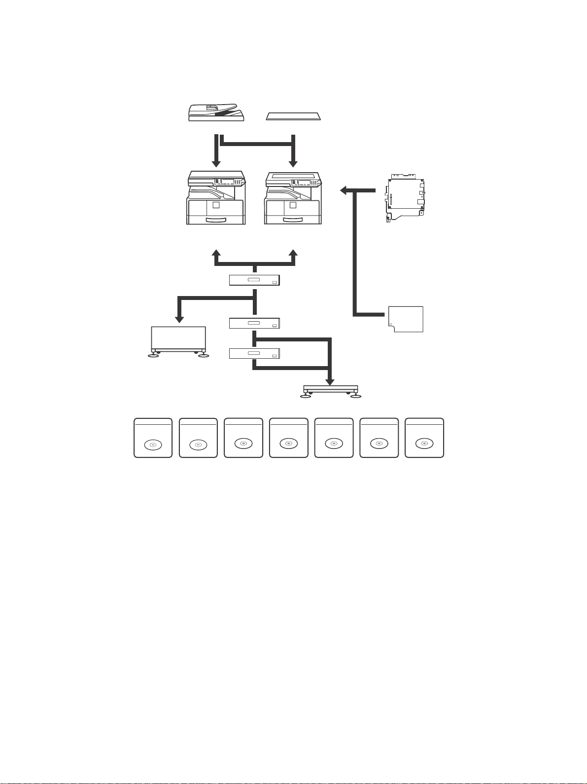
[1] PRODUCT OUTLINE
-8#3
!220
!2
!2$$
!2..
-862
!2."
-8%"
!20"
PRINTER
EXPANSION KIT
MX-USX5
SHARPDESK 5 LICENSE
KIT
-80+
PS3 EXPANSION
KIT
MX-US10
SHARPDESK 10 LICENSE
KIT
MX-US50
SHARPDESK 50 LICENSE
KIT
MX-USA0
SHARPDESK 100 LICENSE
KIT
-8#3
-8#3
!2$3
!2$3
MX-USX1
SHARPDESK 1 LICENSE
KIT
1. System diagram
A. 20/23 cpm machine
AR-6020 CONFIGURATION 1-1
Page 6
!220
!2..
-862
!2."
-8%"
!20"
PRINTER
EXPANSION KIT
MX-USX5
SHARPDESK 5 LICENSE
KIT
-80+
PS3 EXPANSION
KIT
MX-US10
SHARPDESK 10 LICENSE
KIT
MX-US50
SHARPDESK 50 LICENSE
KIT
MX-USA0
SHARPDESK 100 LICENSE
KIT
-8#3
-8#3
!2$3
!2$3
MX-USX1
SHARPDESK 1 LICENSE
KIT
15.Feb
2
2
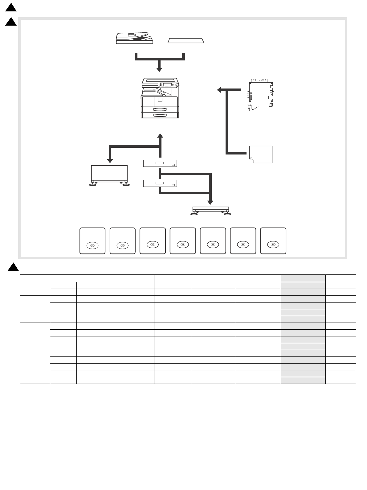
B. 26/31 cpm machine
2
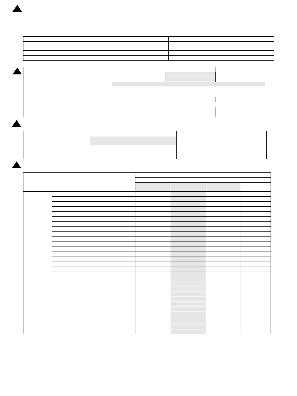
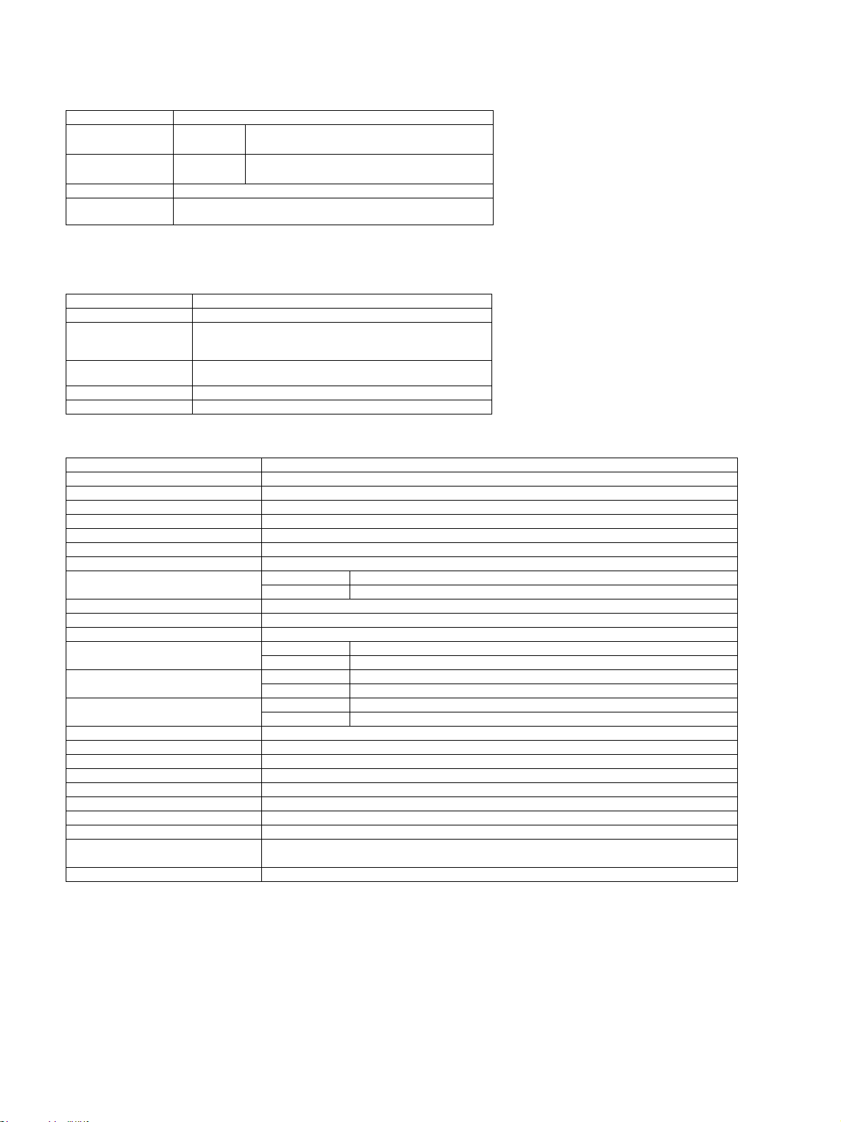
2. Option List
Document
Feed System
Paper Feed
System
Stand
Model/Option AR-6020/6023 AR-6020D/6023D AR-6020N/6023N
AR-RP11 Reversing single pass feeder (RSPF) O O O
MX-VR12 Document cover STD O O
MX-CS12 500-sheet paper feed unit O O O
MX-CS13 500-sheet paper feed unit O O O
AR-DS19 Stand (Large) O O O
AR-DS20 Stand (Small) O O O
AR-NB7 NETWORK EXPANSION KIT O O STD *1
Printer
Expansion
Application /
Solution
AR-PB10 PRINTER EXPANSION KIT
MX-EB14 EXPANSION MEMORY BOARD O O O
MX-PK10 *2 PS EXPANSION KIT O O O
MX-USX1 SHARPDESK 1 LICENSE kit O O O
MX-USX5 SHARPDESK 5 LICENSE kit O O O
MX-US10 SHARPDESK 10 LICENSE kit O O O
MX-US50 SHARPDESK 50 LICENSE kit O O O
MX-USA0 SHARPDESK 100 LICENSE kit O O O
STD: Standard
O
: Option installation enable
*1 The AR-PR10 is required for PCL (SPLC only.)
*2 S/D Model: AR-NB7A; N model: AR-PB10 is necessary.
XX
X
: Option installation disable
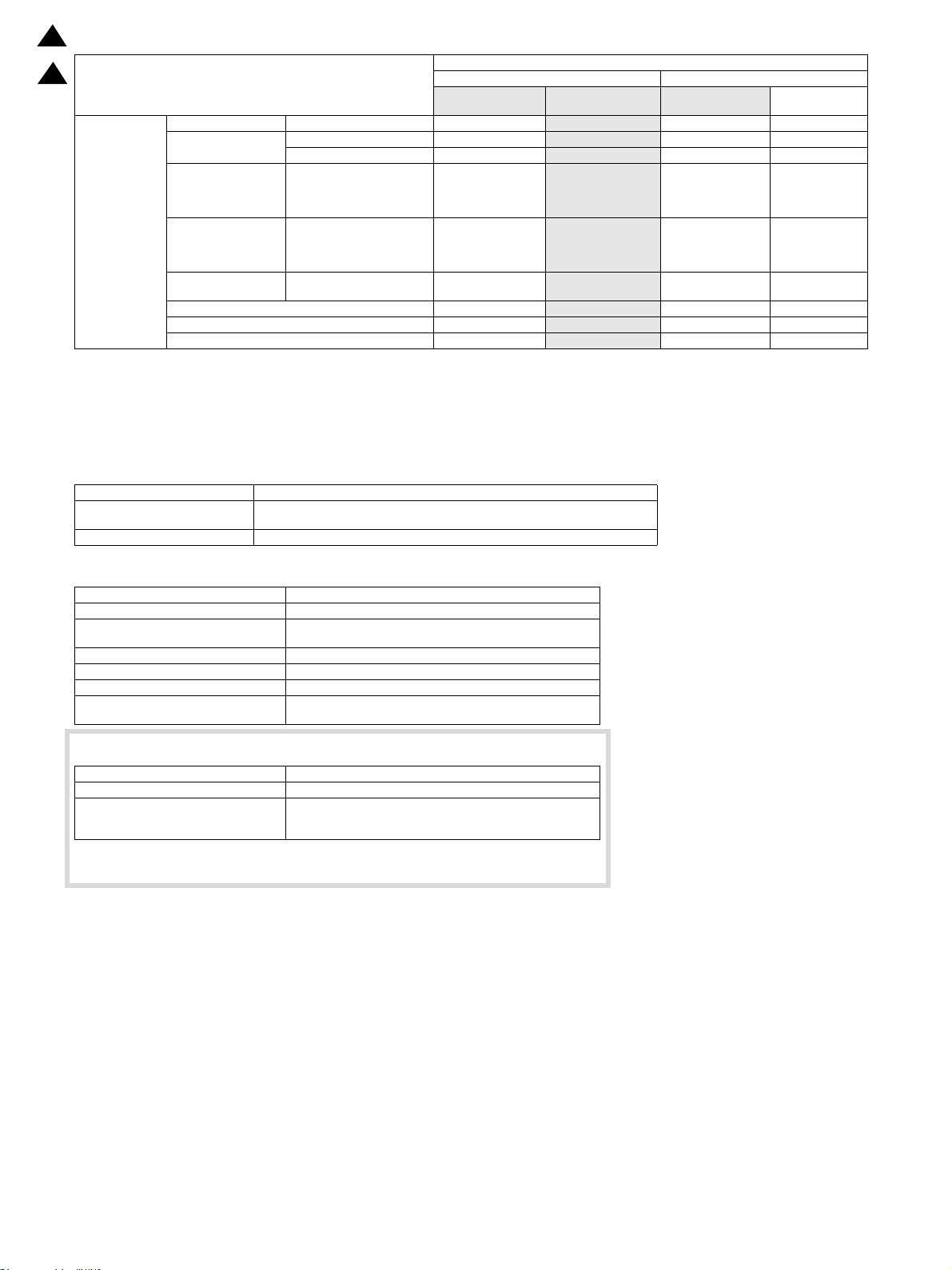
AR-6026N/6031N Note
O
O
STD without motor
O with motor
O
O
STD *1
O O
O
O
O
O
O
O
O
AR-6020 CONFIGURATION 1-2
Page 7
15.Feb
2
AR-6020
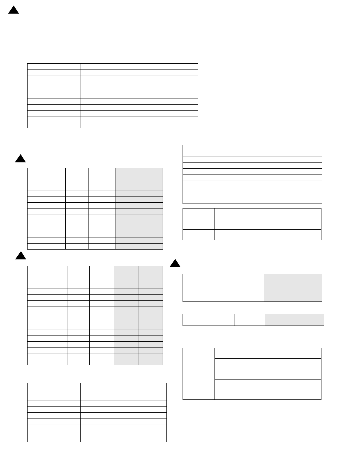
[2] SPECIFICATIONS
1.Basic specifications
A.Engine Composition
Photoconductor OPC Drum (φ30mm)
Recording method Electronic Photo (Laser)
Developing method Dry-type Dual component Magnetic Brush Development
Charging method Charged Saw-Tooth Method
Transfer method Transfer roller
Separation method Separation claw
Cleaning method Contact blade method
Fusing method Heat roller
Toner supply method Open the front cover and insert the cartridge
Toner supply while working Unavailable
Appearance Pastel white
Service Manual
B.Engine speed (ppm)
2
(1)Tra y 1, 2
Paper size (short
edge feed)
A4/ 8.5"x11" 20ppm 23ppm
A4R 14pm 15ppm
8.5"x11"R 15ppm 16ppm
A5/ 5.5"x8.5"R 20ppm 23ppm
B5/ 16K 20ppm 23ppm
B5R 16ppm 18ppm
16KR 15ppm 16ppm
8.5x13" 12ppm 13ppm
B4/ 8.5"x14 12ppm 13ppm
A3 11ppm 12pm
11"x17" 10ppm 11ppm
8K 11ppm 12ppm
2
(2) Bypass tray
Paper size (short
edge feed)
A4 16ppm 18ppm
8.5"x11" 16ppm 18ppm
A4R/ 8.5"x11"R 10ppm 11ppm
A5 16ppm 18ppm
5.5"x8.5" 16ppm 18ppm
A5R/ 5.5"x8.5"R 16cpm 18cpm
B5 16cpm 18cpm
16K 16cpm 18cpm
B5R/ 16KR 10ppm 11ppm
8.5x13" 10ppm 11ppm
B4 10ppm 11ppm
8.5"x14 10ppm 11ppm
A3 10ppm 11ppm
11"x17" 10ppm 11ppm
8K 10ppm 11ppm
20cpm 23cpm
20cpm 23cpm
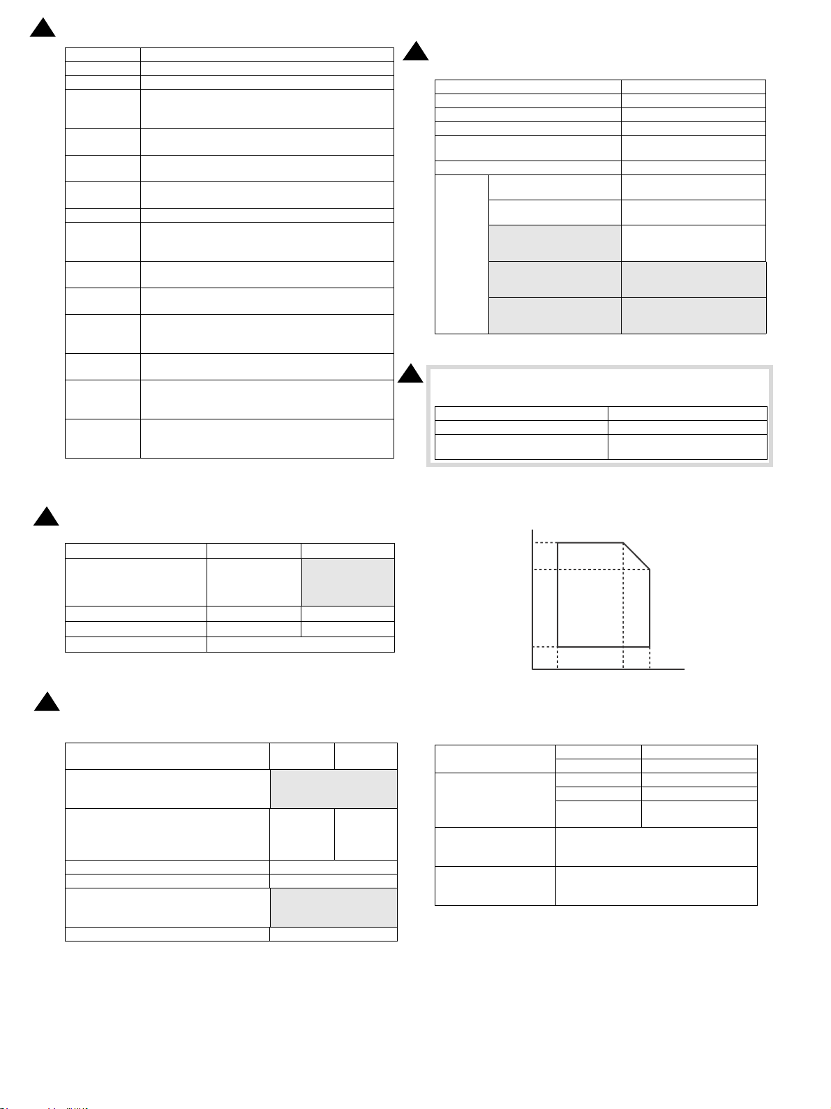
C.Printable area
A3 293x413mm
B4 253x357mm
A4 206x290mm
B5 178x250mm
A5 144x203mm
A5R 203x144mm
8K 266x383mm
16K 191x263mm
11x17 275x425mm
8.5x14 212x349mm
26cpm 31cpm
26ppm 31ppm
18ppm 23ppm
18ppm 23ppm
26ppm 31ppm
26ppm 31ppm
18ppm 23ppm
18ppm 23ppm
16ppm 20ppm
18ppm 23ppm
15ppm 17ppm
15ppm 17ppm
15ppm 17ppm
26cpm 31cpm
24ppm 29ppm
24ppm 29ppm
19ppm 25ppm
25ppm 29ppm
25ppm 29ppm
25ppm 29ppm
24ppm 29ppm
24ppm 29ppm
19ppm 25ppm
16ppm 21ppm
16ppm 21ppm
16ppm 20ppm
15ppm 18ppm
15ppm 18ppm
15ppm 17ppm
A3 293x413mm
B4 253x357mm
A4 206x290mm
8.5x13.5 212x336mm
8.5x13.4 212x333mm
8.5x13 212x323mm
8.5x11 212x272mm
5.5x8.5 136x209mm
5.5x8.5R 209x136mm
Executive 180x260mm
Void area
Image loss
Loss width
Front end: 1 to 4mm, Back end: 1 to 5mm, Both sides:
Max. 6mm
Front end: 4mm or less, Back end: 1 to 5mm, Right/Left :
Total 6mm or less
Front end/Back end: 4mm or less , Right/Left : Total
6mm or less
* When making original size/one-sided copies, the first sheet from
the bypass tray has no back end void setting.
2
D.First Copy Time
26cpm 31cpm
5.2seconds 5.2 seconds
Platen
20cpm 23cpm
A4: 6.4
seconds
LT: 6.5
seconds
A4: 6.4
seconds
LT: 6.5
seconds
First copy time from the paper feeding unit
20cpm 23cpm
Platen 12.5 seconds 12.5 seconds
26cpm 31cpm
10.9 seconds 10.9 seconds
E.Engine resolution
Resolution
Copy
Print
Copy
To ne
Print
<Writing>
600 x 600dpi
<Writing>
600 x 600dpi
<Writing>
600 x 600dpi x 1bit
<Writing>
SPLC : 600 x 600dpi x 1bit
PCL : 600 x 600dpi x 1bit
PS : 600 x 600dpi x 1bit
AR-6020 SPECIFICATIONS 2 – 1
Page 8

2
15.Feb
F. Scanner section
(1)Resolution/Gradation
Scan Resolution for
Copying (dpi)
Transmission Resolution (dpi)
Exposure Lamp White LED
Scan Levels 256 levels
Output Levels
(2)Document table
Form Fixed original glass (Flatbed)
Scan Range 297x431mm
Standard Location of Original Rear Left
Original size detection No
Heater (scanner section) No
2
G.Document feeder
Type RSPF
Scan Speed
Copy
(400x600dpi)
Fax No No
Document Glass 400x600dpi
RSPF 400x600dpi
Refer to Image Send Function.
Monochrome : 1bit
Gray scale : 8bit
Full Color : RGB each color 8bit
Monochrome(A4/
8.5x11)
20/23cpm :
Single:23sides/minute;
Duplex:11 sides/minute;
26/31cpm :
Single:23sides/minute;
Monochrome
Color(A4/8.5x11)
No
Type RSPF
Scan
Original setup direction Upward standard (1toN feeding standard)
Original setup position Center alignment
Original Transport method Sheet-through method
Original feeding order From upper sheet
Original size Standard type
Original weight
Original Stack Capacity
Not transportable original
type
Original size detection Yes
Original size to be detected Auto detection
Original feeding direction Right hand feeding
Original size Guide
Multi copy
Stamp No
1.27 msec/Line(Color), 0.423 msec/
Line(Gray scale/BW)
<Single side>
Plain paper: 50-128g/m2, 13-32 lb.bond
<Double side>
Plain paper: 50-105g/m2, 13-28 lb.bond
Max. 100 sheets (80g/m2, 21 lbs Bond) ,
or Max. height: 1/2 inch, 13mm or less
The following documents are NOT
allowed;
OHP, second original drawing, tracing
paper, carbon paper, thermal paper,
wrinkled/broken/torn document, document with cuts and pastes,
documents printed by an ink ribbon, and
perforated document except
2-punched/3-punched (Perforated document by punch unit is allowed.).
(Center) A3/A4, 11, B4/B5, 8-1/2, A4R/A5,
B5R, 5-1/2
S-S, S-D (Only Duplex model) , D-D (Only
Duplex model) D-S
Standard sheet type
A3
B4
11x17
Type *2
In ch -1 Yes Yes No N o No Ye s Ye s Ye s N o Ye s N o Yes N o N o No No No N o No No
In ch -2 Ye s N o N o No Ye s Ye s Ye s Ye s N o Ye s N o Yes N o N o No No No N o No No
In ch -3 Ye s N o N o Ye s N o Ye s Ye s Ye s N o Ye s N o Yes N o N o No No No No N o N o
AB-1 Yes Yes No No No Yes No No No Yes Yes Yes Yes Yes Yes Yes No No No No
AB -2 Ye s N o N o N o Yes Yes No N o N o Ye s Yes Yes Ye s Ye s Ye s Yes No N o N o N o
AB -3 Ye s N o N o N o Yes Yes No N o N o Ye s Yes Yes Ye s N o No Yes No Ye s Ye s Ye s
AB -4 Ye s N o N o Yes N o Ye s No N o N o Ye s Yes Ye s Yes Yes Ye s Ye s N o No N o N o
AB-5 Yes No Yes No No Yes No No No Yes Yes Yes Yes Yes Yes Yes No No No No
8.5x14
8.5x13.5
8.5x13.4
216x343)
216x340)
8.5x11
8.5x13
216x330)
5.5x8.5
8.5x11R
5.5x8.5R*1
A4
A4R
B5
B5R
A5
8K
A5R*1
16K
16KR
AR-6020 SPECIFICATIONS 2 – 2
Page 9
15.Feb
2
H.Paper feed section
(1)Basic specifications
20/23 cpm 26/31 cpm
Form
Paper loading method To be loaded from the upper side with front loading system To be loaded from the upper side with front loading system
Heater None. None.
Standard: 250-sheet tray x1 + Multi Bypass(100)
Max.: 250-sheet tray x1 + 500-sheet tray x3 + Multi Bypass(100)
Standard: 500-sheet tray x 2 + Multi Bypass (100)
Max: 500-sheet tray x 4 + Multi Bypass (100)
2
Paper Capacity Standard paper (80g/m2) 250 sheets
Paper size detection
Paper Type setting Yes
Paper Size change User setting
Default paper size setting AB systems: A4 Inch systems: 8.5x11 -Paper balance detection Paper empty only
Cassette handle grabbing from both direction Yes -Paper Size Indication Window Depending on Paper Size sheet --
(2)Other paper type capacities
2
Paper Type Paper Tray Bypass Tray
Plain paper
Envelope --
Others -- Single paper feed (transparency, label)
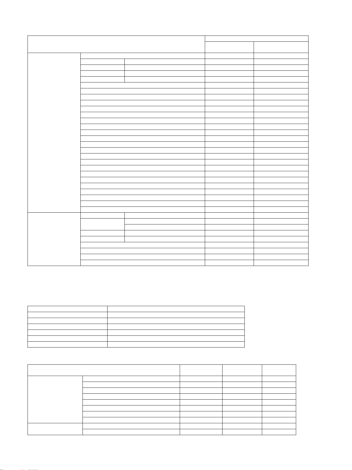
(3)Size of paper which can be fed
2
Paper Size
Item Tray Multi bypass
20/23 cpm
No
20/23 cpm : 250 sheets (80g/m2)
26/31 cpm : 500 sheets (80g/m2)
Tray (250 sheets) Tray (500 sheets) 1 Paper Feed Tray
11x 17 Yes
8.5x14 216x356mm Yes
8.5x13.5 216x343mm Yes
8.5x13.4 216x340 mm Yes
8.5x13 216x330 mm Yes
8.5x11 Yes
8.5x11R Yes
7.25x10.5 *3 No
7.25x10.5R *3 No
5.5x8.5 No
5.5x8.5R Yes
A3 Yes
B4 Yes
A4 Yes
A4R Yes
B5 Yes
B5R Yes
A5 No
A5R Yes
B6R No
A6R No
8K Yes
16K Yes
16KR Yes
Envelope*1 No
Custom No
Extra No
26/31 cpm 20/23/26/31 cpm
500 sheets x2 100 sheets
100 sheets (55-80g/m2)
(For multi paper feed, 55-128g/m2)
AB system: 10 envelopes
Inch system: 5 envelopes
Paper Feeding Section
Main unit Optional tray
(500 sheets)
Yes Ye s Yes
Yes Ye s Yes
Yes Ye s Yes
Yes Ye s Yes
Yes Ye s Yes
Yes Ye s Yes
Yes Ye s Yes
No No Yes
No No Yes
No No Yes
Yes Ye s Yes
Yes Ye s Yes
Yes Ye s Yes
Yes Ye s Yes
Yes Ye s Yes
Yes Ye s Yes
Yes Ye s Yes
No No Yes
Yes Ye s Yes
No No Yes
No No Yes
Yes Ye s Yes
Yes Ye s Yes
Yes Ye s Yes
No No
No No Yes
No No Yes
Multi Bypass
Yes
(Single feed is
available)
AR-6020 SPECIFICATIONS 2 – 3
Page 10
15.Feb
2
2
Tray (250 sheets) Tray (500 sheets) 1 Paper Feed Tray
Thin Paper 55-59g/m2 13-16lb bond Yes
60-105g/m2 16-28lb bond Yes
Recycled Paper Yes
106-128g/m2 28 lb bond 32 lb bond
129-200g/m2 32 lb bond 110 lb C o ver
201g/m2 and above
110 lb bond and above
Paper Type
Plain Paper
Heavy paper
Heavy paper
Heavy paper
OHP paper No
Label *2 No
Tab Paper No
*1: Supporting envelope: Monarch / Com-10 / DL
*2 Recommended media: SF-4A3F
*3 It can be fed, but not display.
I.Paper exit section
(1) Duplex
Type 1 Pass, Switchback type
Transportable Paper (Fixed)
Size/Weight
Other Duplex print using the manual bypass is not possible.
Refer to the “Usable Paper Size and Weight”.
Main unit Optional tray
No
No
No
Paper Feeding Section
(500 sheets)
Yes Ye s Yes
Yes Ye s Yes
Yes Ye s Yes
No No
No No
No No No
No No Yes
No No Yes
No No No
Multi Bypass
Yes
(A4 or less)
(Multi feed is
available)
Yes
(A4 or less)
(Multi feed is
available)
(2) Exit Capacity
Ejection part Center part of the main unit
Ejection method Face-down ejection
Paper capacity for ejection
Ejectable paper size and weight Refer to the “Usable Paper Size and Weight”.
Shifter function No
Detection of ejected paper No
Detection of full ejected paper
(The paper is counted by the software)
250 sheets
(A4/8.5x11:80g/m3)
There is no sensor to detect.
(3) Rotate Sort
Output Tray It is possible to use the Multi Bypass and each paper tray.
Output Paper Size A4/A4R, B5/B5R, 16K/16KR, 8.5”x11”/8.5”x11”R
Output Paper Type
* The output in different 90 degrees direction when using 2 papers
feed trays.
Thin paper(55-59g/m2 13-16 lb bond)
Plain paper(60-105g/m2 16-28 lb bond)
Recycled paper
AR-6020 SPECIFICATIONS 2 – 4
Page 11
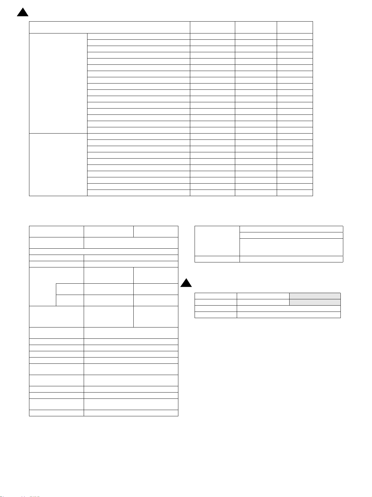
(4) Usable Paper Size and Weight (Main Unit Output Tray, Duplex Section)
11x17 Yes Ye s
8.5x14 216x356mm Yes Yes
8.5x13.5 216x343mm Yes Yes
8.5x13.4 216x340 mm Yes Yes
8.5x13 216x330 mm Yes Yes
8.5x11 Yes Yes
8.5x11R Yes Yes
7.25x10.5 No Yes
7.25x10.5R No Yes
5.5x8.5 No Yes
5.5x8.5R No Yes
A3 Yes Ye s
Paper Size
Paper Type
*1: Supporting Envelope Monarch/Com-10/DL
B4 Yes Ye s
A4 Yes Ye s
A4R Yes Ye s
B5 Yes Ye s
B5R Yes Ye s
A5 No Yes
A5R Yes Ye s
B6R No Yes
A6R No Yes
8K Ye s Ye s
16K Yes Ye s
16KR Yes Ye s
Envelope*1 - Yes
Extra - Yes
Custom - Thin Paper 55-59g/m2 13-16lb bond No Yes
Plain Paper
Heavy paper 106-128g/m2 28 lb bond -32 lb bond No Yes
Heavy paper 129-200g/m2 32 lb bond -110 lb Cover No Yes
Envelope - Yes
OHP - Yes
Label - Yes
Tab Paper - -
60-105g/m2 16-28lb bond Yes Yes
Recycled Paper Yes Yes
Duplex Section
Output Section
Main Unit Output tray
(Non-Offset)
J.Operation panel
(1)Display Device
Form LCD Display with Back Light (custom LCD)
Number of Dots in display 167 segments
Color display Monochrome
LCD Drive Display Area (WxD) 51x77mm
LCD Back Light White LED backlight method
LCD Contrast Adjust No
Angle/Position Adjustment No
(2)Key
Model
Star t K ey O O O
Clear Key O O O
Clear All Key (“CA”) O O O
Basic Input Section
Mode area
Interrupt Key O O O
10 Key O O O
Power Saving Key*1 O O O
* key O O O
# key O O O
Printer Online Key O O O
Scanner Mode Key O O O
AR-6020 SPECIFICATIONS 2 – 5
Simplex model
(Standard model)
Duplex model
(D model)
N model
Page 12
2
15.Feb
Model
Function Selection Key
LED display items
Simplex model
(Standard model)
Ratio Selection Key O O O
Zoom Key O O O
Tray Selection Key O O O
Paper Size Selection Key O O O
Original Key O O O
Paper Key O O O
Exposure Setting Key O O O
Copy Image Quality Mode Selection Key O O O
2in1/4in1 Selection Key O O O
Margin Shift Selection Key O O O
E-Sort Key O O O
Edge/Center Erase Selection Key O O O
Dual Page Copy Key O O O
Duplex Mode Switch Key O O O
One-Touch Send Key(6 keys) O O O
ID Card Copy Key O O O
Interrupt LED O O O
Start Key LED O O O
Power Saving LED O O O
Exposure Setting LED O O O
Copy Image Quality Mode LED O O O
Print Online LED O O O
Scan Mode LED O O O
ID Copy LED O O O
Error LED O O O
Data LED O O O
Duplex model
*1 According to the BA, the icon of Power Saving Key can uses the key (crescent mark) to indicate.
(D model)
N model
K.Controller board
Standard model / Dmodel
CPU
Interface
IEEE1284 Parallel No
IEEE 802.1x No
Ethernet
Interface
Support
Protocol
USB 2.0(High Speed)
(Host) *1
USB 2.0(High Speed)
(Device)
USB Authentication No
ACRE Expansion I/F No
Ir-Simple I/F No
Video I/F No
Serial I/F (for coin
vender)
Parallel I/F (For Coin
Vendor etc,)
Memory Refer to Memory / Hard disk
Memory Slot No
Windows Premium Logo
acquisition
WHQL acquisition Yes
H8S/2373 (16bit 1 chip microcomputer,
24.576MHz)
1 port (When Network
Expansion Kit is
expanded)
10Base-T, 100Base-TX10Base-T, 100Base-
TCP/IP (IPv4) TCP/IP (IPv4)
1 port (Side face)
(When Network
Expansion Kit is
expanded)
1 port
No
Supported by Service boarded
No
*1 Switching to “USB Host invalid” shall be available by Sim.
N-model
1 port
TX
1 port (Side face)
L.Memory/Hard disk
64MB
Memory of MCU
board
Memory Expansion 128MB
M.Warm-up time
2
Warm up time 25 seconds or less
Preheat Yes
Jam recovery time 15 sec
* May be different depending on the environment.
Hard disk : not available
Number of sheets which can be scanned
TEST CHART B : 100 sheets
TEST CHART C : 80 sheets
20/23 cpm model
26/31 cpm model
20 seconds or less
AR-6020 SPECIFICATIONS 2 – 6
Page 13
2. Copy functions
A. Copy Ratio
Item Contents
Copy Ratio (Fixed)
Zoom
Preset Ratio None
XY Zoom
AB Series
Inch Series
Platen
R-SPF
Yes (25-400% for both horizontally and vertically, However, when R-
* It can’t be set when using the RSPF.
B. Exposure/Copy image quality processing
Item Contents
Exposure Mode Auto/Text/Photo
Resolution
Gradation
Number of manual steps 5 steps (Text/Photo)
Toner Save Mode Yes (the setting is different depending on the area)
Writing: 600 x 600 dpi
Scanning: 400 (main) x 600 (sub) dpi (Photo Mode), 400 (main) x
600 (sub) dpi (AE, Text Mode)
Writing : 2 values
Scanning: 256 gradations
C. Copy function
Item Contents
Auto Paper Selection (APS) O
Auto Magnification Selection (AMS) O
Auto Tray Switching O
Support Mixed Original X
Stream Feeding Mode O
Memory Copy (SOPM) O
Rotation Copy O
e-Sort
Rotation Sort O
Sky Shot Prevention X
XY Zoom O
Dual Page Copy
Margin Shift
Edge+Center Erase
B/W Reverse X
2in1 / 4 in 1 O
ID Card Copy O (can enlarge, because the ID Card Copy for all destinations.)
Off-set Print X
Preheat Function O(Terms can be specified by system setting)
Auto Power Shutoff O(Terms can be specified by system setting)
System Setting O
Duplex Copy O(Only for D-model/N-model)
Toner Save Mode
Account Control O(Only copy can be controlled. Number of control: 20)
25%*,50,70,81,86,100,115,122,141,200,400%*
25%*,50,64,77,95,100,121,129,141,200,400%*
25-400%(376 levels by 1%)
50-200%(151 levels by 1%)
SPF is used, 50-200%)
Sort Function O *Except for Interrupt Copy
Group Function O
OC O *Except for enlarged copy
RSPF X
AB series 10mm(5, 10, 15, 20mm)
Inch series 1/2 inch (1/4,1/2,3/4,1 inch)
AB series 10mm(5, 10, 15, 20mm)
Inch series 1/2 inch (1/4,1/2,3/4,1 inch)
O(Can be specified according to area/Settings can be changed by service
simulation)
AR-6020 SPECIFICATIONS 2 – 7
Page 14
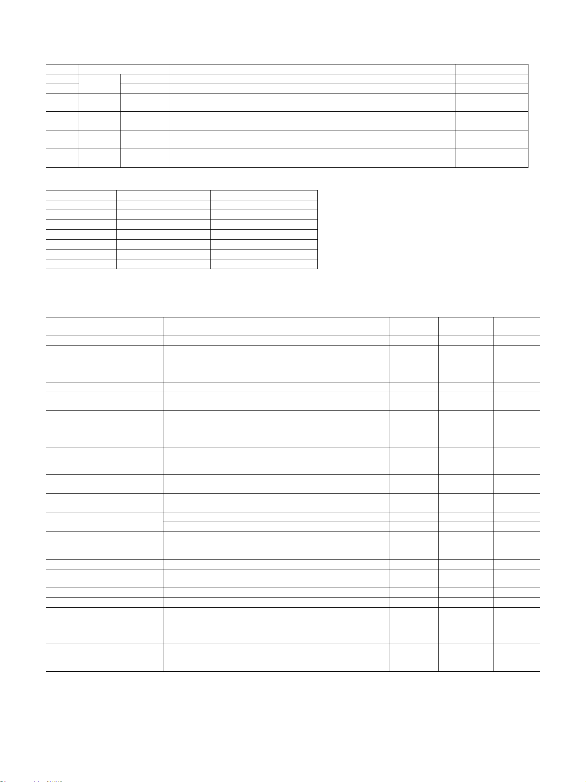
3. Printer function
A. Driver supported OS
USB
Twain/
Button
Manager
Windows
Mac
OS *1
Server 2003 No CD-ROM No CD-ROM No CD-ROM CD-ROM
Server 2003x64 No CD-ROM No CD-ROM No CD-ROM CD-ROM
Server 2008 No CD-ROM No CD-ROM No CD-ROM CD-ROM
Server 2008x64 No CD-ROM No CD-ROM No CD-ROM CD-ROM
Vista CD-ROM CD-ROM CD-ROM CD-ROM No CD-ROM CD-ROM
Vistax64 CD-ROM CD-ROM CD-ROM CD-ROM No CD-ROM CD-ROM
Windows7 CD-ROM CD-ROM CD-ROM CD-ROM No CD-ROM CD-ROM
Windows7x64 CD-ROM CD-ROM CD-ROM CD-ROM No CD-ROM CD-ROM
Windows8 CD-ROM CD-ROM CD-ROM CD-ROM No CD-ROM CD-ROM
Windows8x64 CD-ROM CD-ROM CD-ROM CD-ROM No CD-ROM CD-ROM
Windows8.1 CD-ROM CD-ROM CD-ROM CD-ROM No CD-ROM CD-ROM
Windows8.1 x64 CD-ROM CD-ROM CD-ROM CD-ROM No CD-ROM CD-ROM
Server 2012 x64 No CD-ROM No CD-ROM No CD-ROM CD-ROM
9 No No No No No No No
X 10.2 No No No No No No No
X 10.3 No No No No No No No
X 10.4 No No No No No CD-ROM No
X 10.5 No No No No No CD-ROM No
X 10.6 No No No No No CD-ROM No
X 10.7 No No No No No CD-ROM No
X 10.8 No No No No No CD-ROM No
X 10.9 No No No No No CD-ROM No
*1 New OS is supported according to the rule of the Document Solutions Group.
B. PDL emulation/Font
Network
Twain/
SPLC
Custom
PCL6
Custom
PCL5e
Custom PS PPD
PDL(command) Overseas Resident Font Optional Font
PCL6 compatible OPT
ESC/P(VP-1100) compatible,
ESC/P_super compatible
Postscript3 compatible OPT*1 ---
--- --- ---
European outline font=80 font types
Line printer font (BMP)=1 font types
---
Japanese font
Heisei font = 2 fonts
- Heisei Mincho W3
- Heisei Kaku Gothic W5
Outline font=136 fonts
* When NW Expansion Kit and PS Expansion Kit are expanded, Nova-Light has optional font because it supports PS3.
C. Support print channel
S/D Model N Mode
USB(Device) USB1.1/USB2.0(High-Speed) --- USB1.1/USB2.0(High-Speed)
USB(Host) --- --- --Ethernet --- 10Base-T, 100Base-TX
PSERVER/RPRINT in NetWare environments --- --- ---
LPR --- ---
IPP --- ---
PAP Ether Talk (Apple Talk) --- --- --FTP --- --- --NetBEUI --- --- ---
Raw Port(Port9100) --- ---
HTTP(Web Submit Print) --- --- --POP3(E-Mail To Print) --- --- --BMLinks --- --- ---
* IPP,HTTP, and POP support SSL, but the Russia not support SSL.
Printer Expansion Kit should
be extended for N model
Print channel of UNIX LPR/
LPD command compatible
Print channel compliant with
IPP1.0
Support TCP port of No.9100
(Raw Port)
AR-6020 SPECIFICATIONS 2 – 8
Page 15
D. Direct Print
(1)File Transmission Method
Communication Method Operation Method Support
1
FTP
2 Push Print Send the print instruction from PC to MFP by FTP client software. Yes
3 WEB Page Push Print
4 E-mail Push Print
USB flash
5
drive
Shared
6
Folder
Pull Print After access to FTP service by operation panel and select the file, the printing is performed. No
It can view the data on client PC by the “send a print job” on web page, and send a print
instruction to MFP.
Send the attached data of E-mail to MFP by client PC, the printing is performed. It can enter
the print set instruction in the body of E-mail.
Pull Print
Pull Print
Connect the USB memory to MFP, and select the data in USB memory by operation panel,
the printing is performed.
After access to Shared Folder by operation panel and select the file, the printing is performed.
(2)File Format
File Type Extension Support
TIFF TIFF,TIF Yes*1
JPEG FIF,JPE,JPEG,JPG Yes*1
PCL PCL,PRN,TXT Yes*1
XPS XPS No
PDF PDF Yes*2
Encrypted PDF PDF No (only NULL password*2)
PS PS,PRN Yes*2
*1: Network expansion kit for S/D model and Print expansion kit is needed.
*2: PS expansion kit is needed.
E. Print Function
No
No
No
No
Function Contents
Bar-code Font JetCAPS BarDIMM emulation No No No
Network Tandem Print
ROPM One RIP processing enables plural numbers of printing out. Yes Yes Yes
Multi access support
Paper direction setting for duplex
printing of letter head paper or
punch paper. [Support printing on
logo paper (SEGA AOK Company)]
Driver Distribution Function
Form Overlay
Support Planet Press
Add support font
Bonjour for Macintosh environment
Layout print Various layouts fitted to different print usage are available. Yes No No
Perfect binding
Support Sharp Print System Support Print in anywhere. No No No
Support WSD The Discovery function of printer Yes Yes Yes
Rotation in 90 degrees function
Printing position adjustment for
odd/even pages
2 units of MFP is connected tandem and
writing out is performed by 2 MFP working together. Only when HDD is
installed.
Divide jobs by PC and send them to MFPs.
RIP processing shall be available during printing. And printing shall be
available during scanning.
As for papers having front/back attribute such as letter head or punching
paper, Front/back side and print order shall be corrected at duplex
printing.
The administrator can distribute driver to each client by Sharp Remote
Device Management.
Or it can use MSI to download and install.
The form is downloaded to the MFP in advance and only the data
contents is sent, then fit them into the form by MFP to print.
Support Planet Press by Object if Lune Inc. (software which performs
mapping of form (DL in advance) and variable data inside the printer.)
Support Heisei fonts No Yes No
Support Morisawa fonts No No No
A technology developed by Apple Corps. To detect the peripherals on
the network automatically and connect. It enables users for dynamic
network connection with computers, peripherals and software.
Function that performs saddle stitch print by small amount of pages to
restrain adding of thickness by plural pages binding.
When print image and size is coincide and different direction of paper is
indicated as the paper feed tray, the image is rotated 90 degrees
automatically to print. (However, direction change during job is not
available.)
Printing position of odd/even pages is adjusted. (They can be adjusted
separately.)
Value can be adjusted by the unit of mm/inch
PCL6
compatible
No No No
No No No
No No No
No No No
No No No
No No No
No Yes No
No No No
Yes Ye s Yes
No No No
PostScript3
compatible
SPLC
AR-6020 SPECIFICATIONS 2 – 9
Page 16
Function Contents
It is a function that a certain items are turned ON mandatorily, in order to
restrict the operation by user level. The target operations for restriction
are as follows;
Consideration should be taken in designing, so as to respond to
Print Policy Function
Toner Save Mode Toner Save Mode (1 step) No No No
Support RET Support simulated resolution No No No
Print density adjustment Function to switch in 5 stages. Yes Yes Yes
A4/Letter
Automatic
Switching Function
additional requests.
- User authentication every time
- Forced Retention
- Forced black and white print
- Obtain the login name of Windows
- Accounting Code
Automatic switching while output, it may not out of paper. No No No
PCL6
compatible
No No No
PostScript3
compatible
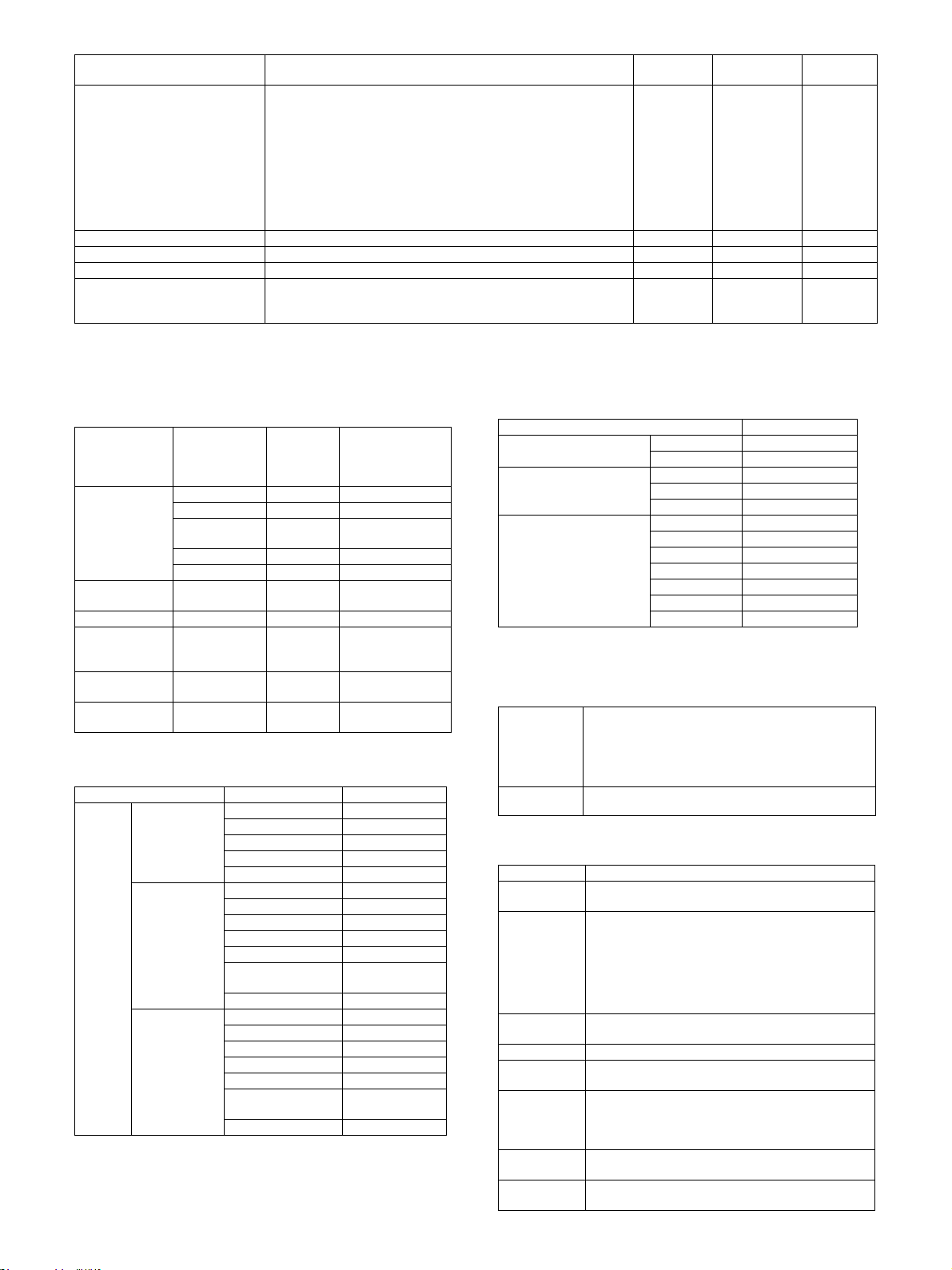
4.Image Send Function
SPLC
A.Overview of Image Send Function
(1)Mode
N model/ S/D
Mode Sub Mode S/D model
E-mail No No
FTP Server No No
Scanner
Internet Fax/
Direct SMTP
Fax - No No
USB Twain Scan
(Including Button
Manager)
Network Twain
Scan
ID Card Scan -
Network Folder
(SMB)
Desktop No No
USB Memory No Yes
-NoNo
-YesNo
-NoYes
No No
Yes (B ut to n
Manager)
(2)Support Image (N model: Standard, S/D model: NW
Expansion Kit is installed)
Mode Type Support
TIFF Yes
File Format
(B/W)
File Format
(Gray Scale)
Scanner
File Format
(Color)
PDF Yes
PDF/A No
Encrypted PDF No
XPS No
Color TIFF Yes
JPEG Yes
PDF Yes
PDF/A No
Encrypted PDF No
Compact PDF(ACRE
installed)
XPS No
Color TIFF Yes
JPEG Yes
PDF Yes
PDF/A No
Encrypted PDF No
Compact PDF(ACRE
installed)
XPS No
model
(NW Expansion
Kit is installed)
No
No
No
(3)Image Processing (N model: Standard, S/D model:
NW Expansion Kit is expanded)
Mode Scanner
Exposure adjustment
Original Type*
Resolution (Different
depending on file format/
sending method)
Auto Yes
Manual 5 levels
Text Yes
Photo Yes
Auto Yes
75x75dpi Yes
100x100dpi Yes
150x150dpi Yes
200x200dpi Yes
300x300dpi Yes
400x400dpi Yes
600x600dpi Yes
*Only can be set in the Monochrome 2 levels.
B.Push Scan (Button Manager)
(System) Shall meet the operating conditions of each OS
Hardware
Environment
Selectable
destination
basically.
(HDD) 8MB or more: 100MB or more is recommended
(Monitor) 800x600dots or more
Shall be able to display 256 colors or more.
(Other) USB port (2.0)
Sharpdesk/ E-mail software/ Fax software/ OCR software/ MS Word/ Any directory
C.Pull Scan (TWAIN)
Item Contents
Interface
Hardware
Environment
Two-sided
Scan
Color Mode B/W(Mono2)/ B/W(Error Diffusion)/Gray Scale/Full Color
Resolution
Scanning
Range
Preview
Function
Zoom Preview
Function
USB Twain: USB
Network Twain*:NIC
(System)Shall meet the operating conditions of each OS
basically.
(HDD) 8MB or more: 100MB or more is recommended
(Monitor) 800x600dots or more
Shall be able to display 256 colors or more.
(Other) USB Twain: USB Port
Network Twain*:Network Port
Yes
75dpi/ 100dpi/ 150dpi/ 200dpi/ 300dpi/ 400dpi/ 600dpi
or Custom: 50-9600dpi (simulated)
A3/ A4/ A4-R/A5-R/ B4/ B5/ B5-R/ Ledger/ Letter/
Letter-R/ Executive/ Executive-R/ Foolscap/ Invoice/
Invoice-R/ Legal/ 8.5x13.4/ 8.5x13.5(343 x216mm)/
Postcard/ 8K/ 16K/ 16K-R/ Auto/ Custom
Yes
Yes
AR-6020 SPECIFICATIONS 2 – 10
Page 17
85%
60%
20%
10°C 30°C 35°C
Humidity (RH)
Temperature
15.Feb
2
Item Contents
Rotation Scan Yes (90 / 180/ 270 degrees)
Quick Scan No
Brightness/
Contrast
Adjustment
Gamma
Adjustment
Color
Matching
Edge
Emphasis
B/W Reverse Yes
Selection of
Light Source
Color
Threshold
Setting
Addition of
Void A re a
Storing of
Setting
Contents
Keeping of
Preview Image
Unit of Display
for Scanning
Range
Notes’
Security
Feature
Auto/ Manual(-100 - +100)
Yes
None / For Printer / For CRT / For LCD / ICM
None / Normal / Sharp / Blur
Yes(Red/ Green/ Blue/ White)
Auto/ Manual (1-254)
Available (Lead Edge/Trail Edge: 2.5mm Right/Left:
3.0mm)
Yes
Yes
Pixel/ mm/ inch
No
* For N model and S/D model while the network expansion kit was
expanded.
2
7. Dimensions and Weight
1 Tray model (Floor to OC) 599(W) x 612(D) x 511(H) mm
1 Tray model (Floor to RSPF) 599(W) x 612(D) x 643(H) mm
4 Trays model (Floor to OC) 599(W) x 612(D) x 940(H)mm
Only main unit (with handle) 599(W) x 612(D) x 1012(H)mm
Main unit (with multi bypass tray
expanded)
Dimensions occupied by the machine 909(W)x 612(D) mm
Main unit (Standard model)
Main unit (Duplex model (D
model))
Main unit (Network supported duplex print model
Weight *
(20/23cpm N-model))
Network supported duplex
print 1 tray model (26/
31cpm N-model)
Network supported duplex
print 2 tray model (26/
31cpm N-model)
599(W)x 612(D) mm
27.9kg(with OC)
33.5kg(with RSPF)
28.2kg(with OC)
33.8kg(with RSPF)
28.4kg(with OC)
34.0kg(with RSPF)
30.9 kg(with OC)
36.5 kg(with RSPF))
36.8 kg(with OC)
42.4 kg(with RSPF)
* Include OPC Drum. Not include Toner/Developer.
2
8. Machine Occupied Area
Standard model/D model/N model
Only main unit (with handle) 599(W)×612 (D)
Main unit (with multi bypass tray
expanded)
909(W)×612(D)
9. Ambient conditions
2
5. Power Source
2
6. Power consumption
Overseas 100V Overseas 200V
20/23 cpm : 220-
Voltage
Frequency
Power code | Sharp model
Power Switch
The full configuration can be operated with the rated power source.
Max. power consumption *1
Power Consumption when Network/Fax
standby: 1W or less
The condition of Network standby: Limited to
connection of the TCP/IP protocol.
Time to go into preheat mode.*2 1min (Default)
Time to come back from preheat mode. 15sec
Time to go into sleep mode.
Time to come back from sleep mode. *3 25sec
100-127V 12A
50/60Hz 50/60Hz
Fixed Type (Direct) Inlet or direct
1 switch
240V 5A
26/31 cpm : 220240V 8A
Overseas
100V
20/23 cpm : 1.2kW or less
26/31 cpm : 1.45kW or
No No
15 min (Default)
After printing out, shut off
immediately (Default 1sec)
Overseas
less
200V
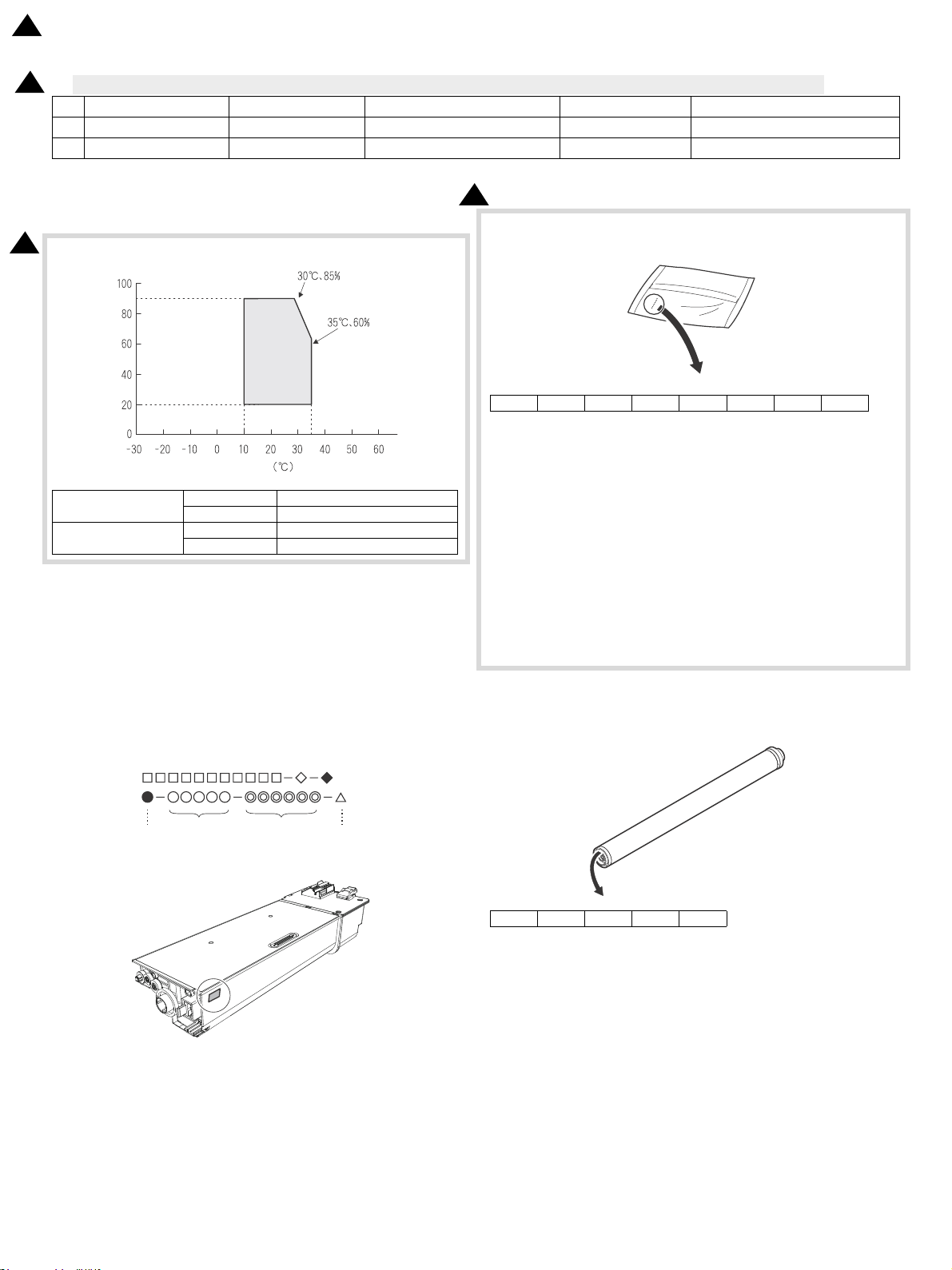
Under the following environmental conditions, the print quality is
guaranteed.
Standard environmental
conditions
Usage environmental
conditions
Supply transportation
environmental conditions
(Term : 2 weeks)
Supply storage
environmental conditions
(unopened)
Temperature 20 - 25 degrees C
Humidity 65 +/- 5 %RH
Temperature 10 - 35 degrees C
Humidity 20 - 85 %RH
Atmospheric
pressure
- 20 - 45 degrees C (no condensation)
- 10 - 40 degrees C (no condensation)
590 - 1013 hPa
(height: 0 - 2000m)
*1: when powered on, the thermal heater is OFF.
*2: Setting Range: 1-60 minutes (Blue Angel Standard)
*3: Revised Energy Conservation, Energy StarVer.2.0, Blue Angel
Standard
AR-6020 SPECIFICATIONS 2 – 11
Page 18
15.Feb
2
[3] CONSUMABLE PARTS
2
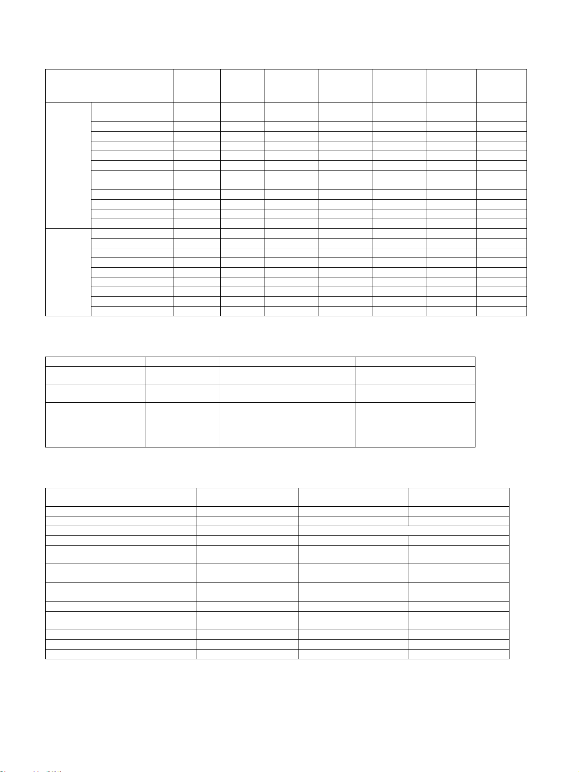
1.Supply system table
A. South and Central America
No. Name Product name Content Life Remark
1 Toner cartridge(Black) MX-237NT Toner cartridge x1 20K Life setting by A4 6% document
2 Developer MX-312NV Developer x1
3 Drum KIT MX-312NR Drum x1
B. Europe
No. Name Product name Content Life Remark
1 Toner cartridge(Black) MX-237GT Toner cartridge x1
2 Toner cartridge(Black) MX-238GT Toner cartridge x1
3 Developer MX-312GV Developer x1
4 Drum KIT MX-312GR Drum x1
20cpm/23cpm : 75K
26cpm/31cpm : 100K
20cpm/23cpm : 75K
26cpm/31cpm : 100K
20K
23K(Toner save mode)
8.4K
10K(Toner save mode)
20cpm/23cpm : 75K
26cpm/31cpm : 100K
20cpm/23cpm : 75K
26cpm/31cpm : 100K
Life setting by A4 6% document
Life setting by A4 6% document
C. Australia, New Zealand
No. Name Product name Content Life Remark
1 Toner cartridge(Black) MX-237GT Toner cartridge x1
2 Toner cartridge(Black) MX-238GT Toner cartridge x1
3 Developer MX-312GV Developer x1
4 Drum KIT MX-312GR Drum x1
20K
23K(Toner save mode)
8.4K
10K(Toner save mode)
20cpm/23cpm : 75K
26cpm/31cpm : 100K
20cpm/23cpm : 75K
26cpm/31cpm : 100K
Life setting by A4 6% document
Life setting by A4 6% document
D. Asia
No. Name Product name Content Life Remark
1 Toner cartridge(Black) MX-237AT Toner cartridge x1
2 Toner cartridge(Black) MX-238AT Toner cartridge x1
3 Developer MX-312AV Developer x1
4 Drum KIT MX-312AR Drum x1
20K
23K(Toner save mode)
8.4K
10K(Toner save mode)
20cpm/23cpm : 75K
26cpm/31cpm : 100K
20cpm/23cpm : 75K
26cpm/31cpm : 100K
Life setting by A4 6% document
Life setting by A4 6% document
E. Middle East, Africa (except Iran)
No. Name Product name Content Life Remark
1 Toner cartridge(Black) MX-237FT Toner cartridge x1
2 Toner cartridge(Black) MX-238FT Toner cartridge x1
3 Developer MX-312FV Developer x1
4 Drum KIT MX-312FR Drum x1
20K
23K(Toner save mode)
8.4K
10K(Toner save mode)
20cpm/23cpm : 75K
26cpm/31cpm : 100K
20cpm/23cpm : 75K
26cpm/31cpm : 100K
Life setting by A4 6% document
Life setting by A4 6% document
AR-6020 CONSUMABLE PARTS 3-1
Page 19
(UMIDITY
4EMPERATURE
5SEENVI
RONMENT
CONDITIONS
Ver.No.Production
place
Serial
number
Year/
Month/
Day
15.Feb
2
2.Maintenance parts list
2
A. Middle East, Africa (except Iran), Europe, Australia, New Zealand, Asia, South and Central America
No. Name Product name Content Life Remark
1 Heat roller MX-312UH Upper heat roller x1 150K
2 Toner filter MX-312TF Toner filter x1 75K
3. Environmental conditions
2
A.Use conditions
Standard environment al
conditions
Usage environmental
conditions
B.Life(packed conditions)
Photoconductor drum (36 months from the production month)
Developer, toner (24 months from the production month)
Temperature 20 - 25 degrees C
Humidity 65 +/- 5%RH
Temperature 10 - 35 degrees C
Humidity 20 - 85%RH
2
<Developer>
12345678
The lot numbe
r is of 8 digits. Each digit indicates the content as follows.
The number is printed on the right under side of the back surface of the
developer bag.
1 Alphabet
Indicates the production factory.
2 Number
Indicates the production year.
3, 4 Number
Indicates the production month.
5, 6 Number
Indicates the production day.
7 Hyphen
8 Number
Indicates the production lot.
4. Production number identification
<Toner cartridge>
The label on the toner cartridge shows the date of production.
<Drum>
ser print indicates the model conformity code and the date (year,
The la
month, day) of production.
12345
1 Alphabet
Indicates the model conformity code. L for this model.
2 Number
Indicates the end digit of the production year.
3 Number or X, Y, Z
Indicates the month of packing.
X stands for October, Y November, and Z December .
4, 5 Number
Indicates the day of the month of packing.
AR-6020 CONSUMABLE PARTS 3-2
Page 20
AR-6020/6023/
6020D/6023D
with Network
Expansion Kit
AR-6020N/6023N/
6026N/6031N and
AR-6020/6023/
6020D/6023D
with Network
Expansion Kit
15.Feb
2
[4] EXTERNAL VIEWS AND INTERNAL STRUCTURES
2
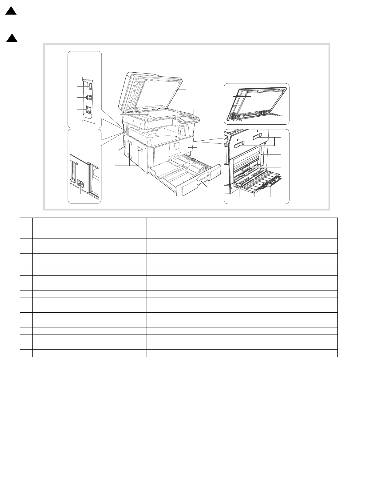
1. External view
No. Name Function/Operation
USB 2.0 connector (Type A) (when the network
1
ansion kit is installed)
exp
Connect to the USB device.
2 Glass cleaner (when the RSPF is installed) Use to clean the original scanning glass.
3 Document glass Place an original that you wish to scan face down here.
4 Handles Use to move the machine.
5 Power switch Press to turn the machine power on and off.
6 Centre tray Copies and printed pages are output to this tray.
7 Operation panel Contains operation keys and indicator lights.
8 Front cover Open to remove paper misfeeds or replace the toner cartridge.
9 Paper trays The tray holds 250 sheets of paper.
10 Document cover (when installed) Open to make a copy from the document glass.
11 Side cover Open to remove misfeed paper.
12 Side cover handle Pull to open the side cover.
13 Bypass tray guides Adjust to the width of the paper when using the bypass tray.
14 Bypass tray Special paper (heavy paper or transparency film) can be
15 Bypass tray extension Pull out when feeding large paper such as A3 and B4 (11" x 17" and 8-1/2" x 14").
16 USB 2.0 connector Connect to your computer to use the printer and scanner functions.
17 10BASE-T/100BASE-TX LAN connector Connect to your network to use the pr
inter and scanner functions.
fed from the bypass tray.
AR-6020 EXTERNAL VIEWS AND INTERNAL STRUCTURES 4-1
Page 21

2. Internal view
No. Name Function/Operation
1 Toner cartridge lock release lever To replace the toner cartridge, pull out the to
2 Toner cartridge Contains toner.
3 Fusing unit release levers To remove the paper misfeed in the fusing unit, push down on these levers and remove the paper.
4 Roller rotating knob Rotate to remove misfeed paper.
5 Photoconductive drum Images are formed on the photoconductive drum.
6 Fusing unit paper guide Open to remove misfeed paper.
ner cartridge while pushing on this lever.
AR-6020 EXTERNAL VIEWS AND INTERNAL STRUCTURES 4-2
Page 22
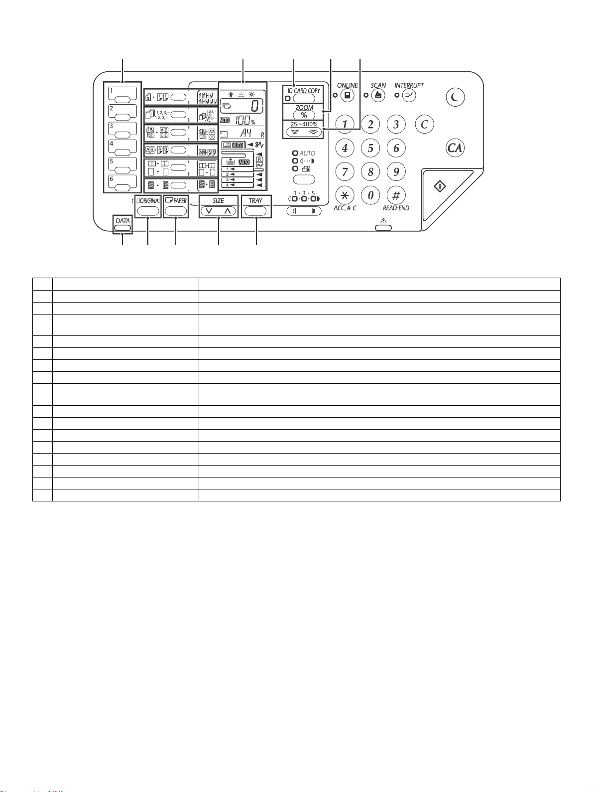
3. Operation panel
1
2
3
4
5
6
7
12 13 14 15 16
891011
No. Name Function/Operation
1 SCAN MENU key Use to scan by means of the provided Button Manager software and Scan to USB.
2 ORIGINAL TO COPY key/indicator Press to select duplex copy.
SORT/GROUP/ROTATE SORT key /
3
indicators
4 2 IN 1 / 4 IN 1 key / indicators Press to select the "2 IN 1" or "4 IN 1" mode.
5 DUAL PAGE COPY key / indicator Use to make individual copies of the two pages of an ope
6 ERASE key / indicators Press to select the "CENTER ERASE" or "ED
7 MARGIN SHIFT key / indicator Shifts text or image on the copy to leave a binding
8 Display
9 ID CARD COPY key/indicators Press to use ID Card copy.
10 Zoom key Hold down when the machine is not in use to display the copy ratio in the display.
11 Copy ratio keys Use to select any reduction or enlargement copy r
12 DATA NOTIFICATION indicator (Green) The indicator lights solidly or blinks to indicate the status of a job.
13 ORIGINAL key Use to enter the original size.
14 PAPER key Use to set the paper size in the paper trays..
15 SIZE key Use to select a paper size.
16 TRAY SETTING key Use to manually select a paper tray.
Press to select the "SORT", "GROUP" or "ROTATE SORT" mode.
n book or other two-page original.
GE + CENTER ERASE" mode.
margin on the edge of the copy.
Shows the set number of copies, as well as the copy r
an error code when an error occurs.
atio, system setting function or setting code, or
atio from 25% to 400% in increments of 1%.
AR-6020 EXTERNAL VIEWS AND INTERNAL STRUCTURES 4-3
Page 23
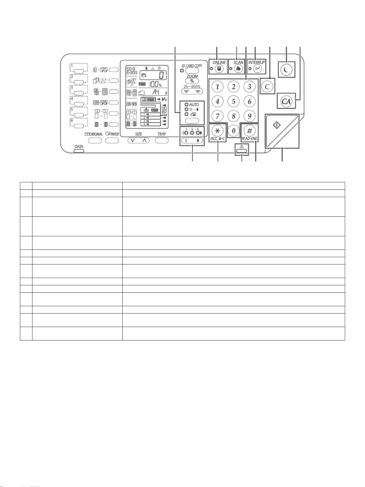
No. Name Function/Operation
13
45
9 10 11 12
26
8
7
13
1 AUTO/TEXT/PHOTO key indicators Use to select the exposure mode: "AUTO", "TEXT", or "PHOTO".
Press to toggle the machine between online and off-line. T
2 ONLINE key indicator
3 SCAN key indicator
4 Numeric keys
5 INTERRUPT key indicator Interrupts a copy run.
6 CLEAR key Clears the copy quantity display or
7 POWER SAVE key indicator
8 CLEAR ALL key Press to return the copy and scan settings to the initial settings.
9 Light and Dark keys indicators The selected exposure level indicator lights up.
10 Audit clear key
11 Error indicator Lights solidly or blinks to indicate the status of the error.
12 READ-END key
13 START key indicator
online, and goes off when the machine is off-line.
The indicator blinks while the machine is receiving pr
Press to switch the machine to scanner mode and scan by means of the provided Button Manager
sof
tware.
The indicator blinks during scanning and tr
Use to select the desired copy quantity or to
To display the total number of pages output by the machine, hold the [0] key down.
Use to switch the machine to "Auto power shut-off" mode, which is a power save function.
[Power save key] blinks when the machine is in an auto power shut-off mode.
While using the copy enabling the auditing mode, press to retur
waiting for account number-in.
Copying starts if you press this key when you che
finished scanning the original pages.
Press to make a copy. Also, press to configure the system
indicator is on.
ansmission of the scanned data.
make system setting entries.
terminates a copy run.
ck the total number of copies made and have
he indicator lights up when the machine is
int data and while printing is paused.
settings. Copying is possible when the
n the machine to the status of the
AR-6020 EXTERNAL VIEWS AND INTERNAL STRUCTURES 4-4
Page 24

<20/23/26/31 cpm>
<26/31 cpm>
15.Feb
2
4. Motor, solenoid, clutch
2
No. Name Code Function operation
1 Mirror motor MIRM Drives the optical mirror base (scanner unit).
2 Toner motor TNM_D Toner supply
3 Duplex motor ADUM Switchback operation and paper exit motor in duplex.
4 Main motor MM Drives the machine.
5 1st tray paper feed clutch C1PUC Drives the pick up roller
6 PS clutch RRC Drives the resist roller
7 Bypass tray paper transport clutch MPFC Drives the bypass tray paper transport roller.
8 Ozone exhaust fan OZFM
9 Power supply unit cooling fan PSFM Cools the Power supply unit.
2
10 Paper tray lift motor C1LUM Lifts the paper feed tray.
11 LSU cooling fan LSUFM Cools the LSU and the Developing unit.
Cools the inside of the machine and discharges the ozone.
AR-6020 EXTERNAL VIEWS AND INTERNAL STRUCTURES 4-5
Page 25

15.Feb
2
5. Sensor, switch
2
No. Name Code Function operation
1 Mirror home position sensor MHPS Detects the mirror (scanner unit) home position.
2 Side door/Front cover switch DSWR/DSWF Side door/Front cover open detection
3 Paper exit sensor (paper exit side) POD Detects paper exit.
4 Paper exit sensor (DUP side) POSD Paper tra nsport detection
5 Thermistor
6 Thermostat RDTCT Fusing section abnormally high temperature detection
7 Toner density sensor TCS Detects the toner density in the developing unit.
8 Bypass tray sensor MPED Bypass tray transport detection
9 Paper in sensor PIN Paper transport detection
10 Tray empty C1SS Tray paper entry detection
11 Power switch MAIN SW Turns ON/OFF the main power source.
12 Temperature sensor TH_RA
13 Paper feed tray 1 paper empty detector C1PED Detects paper empty in Paper feed tray 1
14 Toner motor sensor TM_COUNT Detects the rotation of the toner motor.
15 Paper width sensor MPWD
2
16 Paper feed tray upper limit detector C1LUD This detector detects when the tray in paper feed tray reaches its upper limit.
17 Temperature / humidity sensor HUD_RA/TH_RA
TH_US_IN
UM_IN
TH_
Fusing section temperature detection
Detects the temperature around the machine. This is only for 20/23cpm
chine.
ma
Detects the paper width. (Manual paper feed tray)
Detects the temperature and the humidity around the machine. This is only for
26/31cpm machine.
AR-6020 EXTERNAL VIEWS AND INTERNAL STRUCTURES 4-6
Page 26

6. PWB
1
2
4
3
7
9
5
8
6
No. Name Function operation
1 LED drive PWB Copy lamp control
2 CCD PWB Image scanning
3 MCU PWB Main control PWB
4 High voltage PWB High voltage control
5 DC PWB DC power control
6 OPE PWB Operation panel input/Display, operation p
7 USB I/F PWB Connect a USB device
8 LCD Shows various messages.
9 NNB PWB Network interface PWB
anel section control
AR-6020 EXTERNAL VIEWS AND INTERNAL STRUCTURES 4-7
Page 27
14 5 6
7
18
3 2
8
9
11
12
14
15
16
10
22
13
19 201721
19
21
19
21
<20/23/26/31 cpm> <26/31 cpm>
15.Feb
2
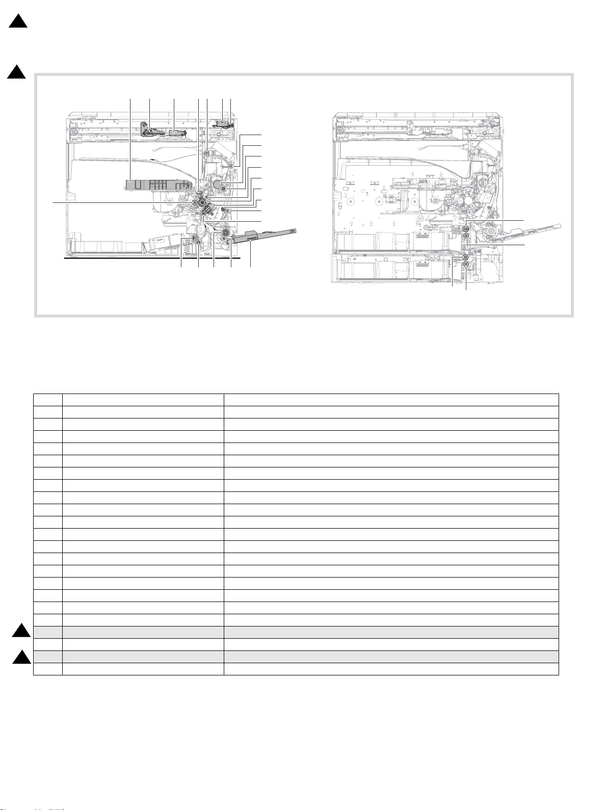
7. Cross sectional view
2
No. Name Function/Operation
1 Copy lamp Image radiation lamp
2 Copy lamp unit Operates in synchronization with No. 2/3 mir
3 LSU unit Converts image signals into laser beams to write on the drum.
4 Lens unit Reads images with the lens and the CCD.
5 MC holder unit Supplies negative charges evenly on the drum.
6 Paper exit roller Used to discharge paper.
7 Transport roller Used to transport paper.
8 Upper heat roller Fuses toner on paper (with the teflon roller).
9 Lower heat roller Fuses toner on paper (with the silicon rubber roller).
10 Waste toner transport roller Transports waste toner to the waste toner box.
11 Drum unit Forms images.
12 Transfer roller unit Transfer images (on the drum) onto paper.
13 DUP follower roller Transports paper for duplex.
14 Duplex transport roller Transports paper for duplex.
15 Resist roller Takes synchronization between the paper lead edge and the image lead edge.
16 Bypass tray Bypass tray
17 Bypass tray paper pick up roller Picks up paper in bypass tray.
18 No. 2/3 mirror unit
2
19 Tray separation roller Separates a document to prevent double-feeding.
20 Bypass tray separation roller
21 Tray paper feed roller Picks up paper from the tray.
2
22 MG roller Puts toner on the OPC drum.
Reflects the images from the copy lamp unit to the lens unit.
Separates a document to prevent double-feeding. (Bypass tray)
ror unit to radiate documents sequentially.
AR-6020 EXTERNAL VIEWS AND INTERNAL STRUCTURES 4-8
Page 28
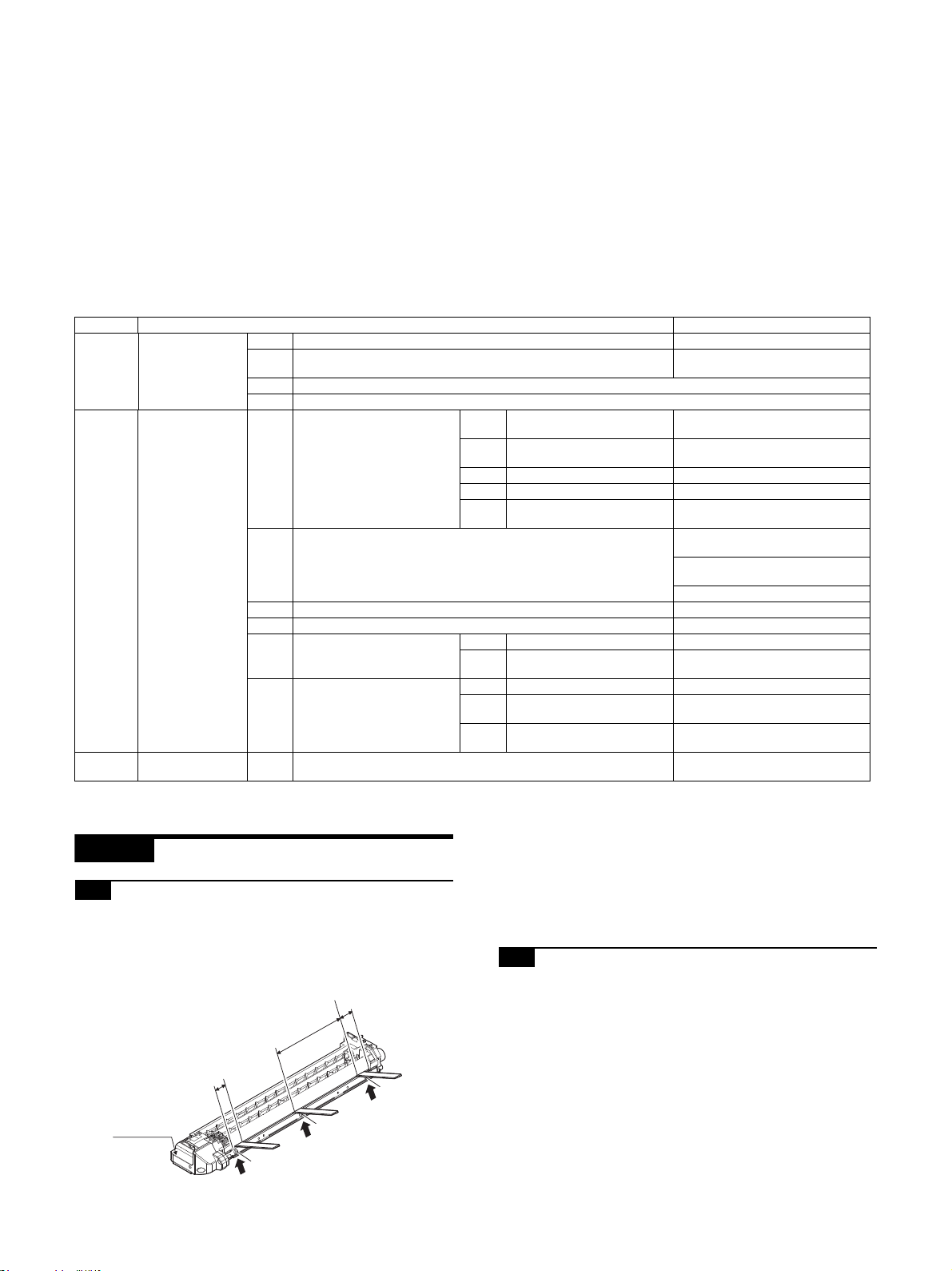
20mm
20mm
150mm
A
A
A
DV front cover
2
3
1
AR-6020
[5] ADJUSTMENTS
Service Manual
1. General
Each adjustment item in the adjustment item list is associated with a specific Job number. Perform the adjustment procedures in the sequence
of Job numbers from the smallest to the greatest.
However, there is no need to perform all the adjustment items. Perform only the necessary adjustments according to the need.
Unnecessary adjustments can be omitted. Even in this case, however, the sequence from the smallest to the greatest Job number must be
observed.
If the above precaution should be neglected, the adjustment would not complete normally or trouble may occur.
2. Adjustment item list
Job No Adjustment item list Simulation
1-A Developing doctor gap adjustment Developing doctor gap adjustment
ADJ 1 Process section
ADJ 2 Mechanism section
ADJ 3
Image density
adjustment
1-B MG roller main pole position adjustment
1-C Developing bias voltage adjustment
1-D Grid bias voltage adjustment
Lead edge image position
(1)
adjustment
RSPF copy lead edge position
(2)
2-A Image position adjustment
2-B Main scanning direction (FR direction) distortion balance adjustment
2-C Scan image (sub scanning direction) distortion adjustment Winding pulley position adjustment
2-D Main scanning direction (FR direction) magnification ratio adjustment SIM 48-1
Sub scanning direction (scan-
2-E
ning direction) magnification
ratio adjustment
2-F Off center adjustment
3-A Copy mode image density adjustment
adjustment
(3) Rear edge void adjustment SIM50-1, SIM50-19
(4) Paper off center adjustment SIM50-10
Side edge void area adjust(5)
ment
(1) OC mode in copying SIM 48-1
RSPF sub scanning direction
(2)
magnification ratio
(1) OC mode SIM 50-12
RSPF original off-center
(2)
adjustment
Mechanical off-center adjust(3)
ment
MG roller main pole position adjustment
SIM50-10
SIM50-6
SIM26-43
No. 2/3 mirror base unit installing
position adjustment
Copy lamp unit installing position
adjustment
Rail height adjustment
SIM 48-5
SIM 50-12
---
46-2
SIM
3. Details of adjustment
ADJ 1 Process sectio n
1-A Developing doctor gap adjustment
1) Loosen the developing doctor fixing screw A.
2) Insert a thickness gauge of 1.5mm to the three positions at
20mm and 150mm from the both ends of the developing doctor as shown.
AR-6020 ADJUSTMENTS 5 – 1
3) Push the developing doctor in the arrow direction, and tighten
the fixing screws of the developing doctor in the sequence of
13233.
4) Check the clearance of the developing doctor. If it is within the
specified range, then fix the doctor fixing screw with screw
lock.
* When inserting a thickness gauge, be careful not to scratch
the developing doctor and the MG roller.
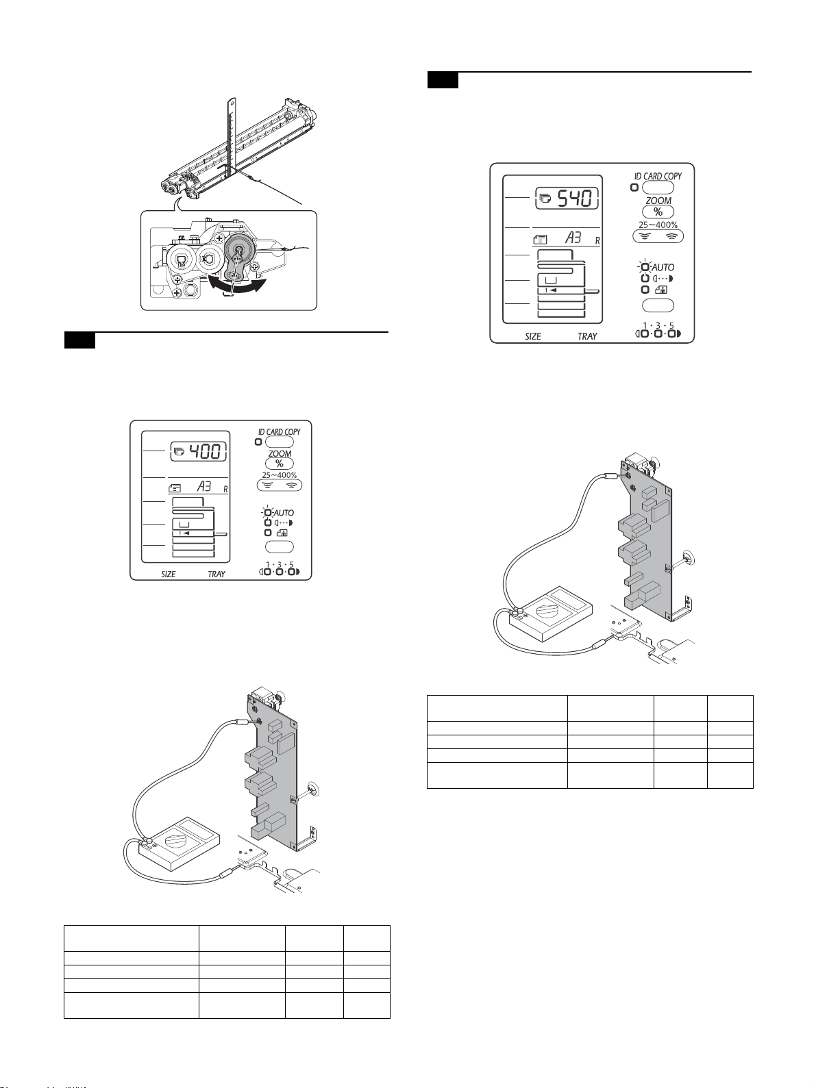
1-B MG roller main pole position adjustment
1) Remove the DV front cover, and put the developing tank on a
flat surface.
2) Tie a string to a needle or a pin.
3) Hold the string and bring the needle close to the MG roller horizontally. (Do not use paper clip, which is too heavy to make a
correct adjustment.) (Put the developing unit horizontally for
this adjustment.)
4) Do not bring the needle into contact with the MG roller, but
bring it to a position 2 or 3mm apart from the MG roller. Mark
the point on the MG roller which is on the extension line from
the needle tip.
5) Measure the distance from the marking position to the top of
the doctor plate of the developing unit to insure that it is 18mm.
Page 29
If the distance is not within the specified range, loosen the fix-
2
3
4
2
3
4
ing screw A of the main pole adjustment plate, and move the
adjustment plate in the arrow direction to adjust.
1-C Developing bias voltage adjustment
NOTE: Use a digital multi-meter with an internal resistance of
10Mohm or more.
1) Execute SIM 8-1.
1-D Grid bias voltage adjustment
NOTE: Use a digital multi-meter with an internal resistance of
10Mohm or more.
1) Execute SIM 8-2.
2) Touch the exposure mode to be changed.
The current set value is displayed.
3) Enter the set value with the 10-key.
4) Press the [START] key.
Output is made with the entered value, and the display returns
to the original state.
2) Touch the exposure mode to be changed.
The current set value is displayed.
3) Enter the set value with the 10-key.
4) Press the [START] key.
Output is made with the entered value, and the display returns
to the original state.
<SIM8-1>
LED Output mode
AUTO indicator COPY 0 - 650 400
TEXT indicator COPY-TSON 0 - 650 320
PHOTO indicator PRINTER 0 - 650 400
TEXT indicator & PHOTO
indicator
PRINTER-TSON 0 - 650 400
Setting
range
Default
<SIM8-2>
LED Output mode
AUTO indicator COPY 0 - 750 540
TEXT indicator COPY-TSON 0 - 750 460
PHOTO indicator PRINTER 0 - 750 540
TEXT indicator & PHOTO
indicator
PRINTER-TSON 0 - 750 540
Setting
range
Default
AR-6020 ADJUSTMENTS 5 – 2
Page 30

A4(8.5" x 11")
Paper rear edge
A4(8.5" x 11")
A4(8.5" x 11")
Paper rear edge
ADJ 2 Mechanism section
NOTE: If a jam error or paper empty occurs during copying in the
adjustment by the simulation, the image data is not saved,
and therefore recopying is required.
2-A Image position adjustment
2-A (1)Lead edge image position adjustment
NOTE: This adjustment executes the copy image position and the
lead edge void amount adjustment.
By adjusting the image reading start position and the print
start position (the registration roller ON timing) under the
100% printing.
<How to operate>
When this adjustment is executed, the current setting value is displayed in 2-digits. (The center value is 50.)
The switching of each setting and display can be made with pressing the [AUTO/TEXT/PHOTO] key.
When the adjustment value is entered by the [Numeric] keys and
press the [START] key, the setting value is saved and the machine
makes one copy. (The setting value range is from 1 to 99.)
When the [INTERRUPT] key is pressed, the process is interrupted
and the machine goes into the sub code input standby mode. When
the [CA] key is pressed, the simulation is terminated.
When this adjustment is executed with the original cassette tray,
the adjustment values of all cassette trays becomes the same
value.
(When the adjustment value is increased by 1, the position is
shifted by 0.1mm.)
C = 10 x R (mm)
When the C value is increased by 10, the image loss amount is
decreased in 1mm.
4) Measure the distance between the lead edge of the paper and
the image printing start position (H mm). Then, set the value
(A) by calculating with the following formula.
Paper rear edge
A = 10 x H (mm)
When the A value is increased by 10, the image lead edge
moves to the paper lead edge in 1mm.
5) Set the lead edge adjustment value (B) to 50 (2.5mm).
LED Adjustment mode
AUTO, 1st tray indicator
AUTO, 2nd tray indicator
AUTO, Bypass tray indicator
TEXT indicator
PHOTO indicator
AUTO, TEXT, PHOTO indicator
Print start position (1st tray paper feed)
Print start position (2nd tray paper feed)
Print start position (Bypass tray paper feed) *
Image lead edge void amount
Image reading start position
Image rear edge void amount
* Supported for the installed models only. Skipped for the models
without installation.
When printing is made with bypass tray, use A3 paper with the AB
destination or the W-letter with the Inch destination.
When the adjustment value of the print start position is increased
by 1, the timing of the registration roller is delayed and the printing
image is cut in 1mm. When the adjustment value of the image
reading start position is increased by 1, the image reading start
position is shifted to home position (towards you) in 1mm.
1) Enter SIM50-01 mode.
2) Set the following setting value to [1] by [Numeric] keys and
press the [START] key. Then, print one copy.
Item A: The print start position (The [AUTO] indicator lights. )
Item B: The image lead edge void amount (The [TEXT] indicator lights.)
Item C: The image reading start position (The [PHOTO] indicator lights.)
3) Measure the image loss amount (R mm) of the scale. Then,
set the value (C) by calculating with the following formula.
When the B value is increased by 10, the void area is
expanded in 1mm.
When the B value is set to less than 25, the void amount
becomes 0.
2-A (2)RSPF copy lead edge position
adjustment
NOTE: This adjustment executes the RSPF copy lead edge posi-
tion adjustment.
<How to operate>
When the adjustment value of the paper reading position is
increased by 1, the timing of the reading start becomes faster and
the machine reads the paper faster in 0.1mm amount.
When the adjustment value of the paper reading position is
increased by 1, the image reading start position is shifted to the
reverse direction. The adjustment range is from 1 to 99.
LED Adjustment mode
AUTO indicator
TEXT indicator
PHOTO indicator
* Supported for the installed models only. Skipped for the models
without installation.
1) Set a scale on the OC table as shown below.
1st print surface paper reading position adjustment
2nd print surface paper reading position adjustment *
Rear void adjustment (RSPF)
AR-6020 ADJUSTMENTS 5 – 3
Page 31

2) Make a copy, Then use the copy output as an original to make
A4(8.5" x 11")
Paper rear edge
Scale image
Paper rear edge
Void amount (Standard value: 4mm or less)
an RSPF copy again.
3) Check the copy output. If necessary, perform the following
adjustment procedures
4) Execute SIM 50-6.
5) Set the RSPF lead edge position set value (AUTO indicator
ON) so that the same image is obtained as that obtained in the
previous OC image lead edge position adjustment.
LED Adjustment mode
AUTO indicator
TEXT indicator
PHOTO indicator
Front document scan position adjustment
Back document scan position adjustment*
Rear edge void adjustment (RSPF)
2-A (3)Rear edge void adjustment
NOTE: This adjustment executes the rear edge void adjustment.
<How to operate>
When the adjustment value of the paper reading position is
increased by 1, the timing of the reading start becomes faster and
the machine reads the paper faster in 0.1mm amount.
When the adjustment value of the paper reading position is
increased by 1, the image reading start position is shifted to the
reverse direction. The adjustment range is from 1 to 99.
LED Adjustment mode
AUTO indicator
TEXT indicator
PHOTO indicator
* Supported for the installed models only. Skipped for the models
without installation.
1) Set a scale as shown in the figure below.
2) Set the document size to A4 (8.5" x 11"), and make a copy at
100%.
3) If necessary, perform the following adjustment procedure.
4) Execute SIM 50-1 and set the density mode to AUTO + TEXT
+ PHOTO (Rear edge void).The currently set adjustment value
is displayed.
5) Enter the set value and press the [START] key. The correction
value is stored and a copy is made.
<Duplex mode adjustment>
* 1st print surface (auto duplex) rear edge void adjustment:
SIM50-19 <<AUTO>>
*2nd print surface (auto duplex) rear edge void adjustment:
SIM50-19<<TEXT>>
*Set to S -> D mode before execution.
1st print surface paper reading position adjustment
2nd print surface paper reading position adjustment *
Rear void adjustment (RSPF)
AR-6020 ADJUSTMENTS 5 – 4
NOTE: Before performing the 2nd print surface rear edge void
adjustment, be sure to perform the 2nd print surface lead
edge position adjustment. Never reverse the sequence.
<Adjustment specification>
Adjustment mode SIM LED
AUTO
+
Rear edge void SIM 50-1
1st print surface
rear edge void
2nd print surface
rear edge void
SIM 5019*
SIM 5019*
TEXT
+
PHOT
O
AUTO
TEXT
Set
value
1 step:
0.1m
m shift
Spec
value
4mm or
less
Set
range
1 - 99
*Set to S -> D mode before execution.
2-A (4)Paper off center adjustment
NOTE: This adjustment executes the copy image on the copy and
the center offset position of paper reading adjustment.
<How to operate>
When the adjustment value is entered by the [Numeric] keys and
press the [START] key, the setting value is saved and the machine
makes one copy. (The setting value range is from 1 to 99.)
When the [INTERRUPT] key is pressed, the process is interrupted
and the machine goes into the sub code input standby mode. When
the [CA] key is pressed, the simulation is terminated.
(When the adjustment value is increased by 1, the position is
shifted by 0.1mm.)
LED Adjustment mode
AUTO, 1st tray indicator
AUTO, 2nd tray indicator
AUTO, 3rd tray indicator
AUTO, 4th tray indicator
AUTO, Bypass tray indicator
TEXT, 1st tray indicator
* Supported for the installed models only. Skipped for the models
without installation.
When the 2nd printer center offset is selected, the duplex setting
becomes the S-D.
When the adjustment value of the print center offset is increased,
the image position is shifted to the right. When the adjustment
value of the print center offset is decreased, the image position is
shifted to the left.
When the larger value is set, the black banding could be appeared
due because the machine reads the outside of the shading area.
When printing is made with bypass tray, use A3 paper with the AB
destination or the W-letter with the Inch destination.
When the 2nd print center offset is adjusted by reading from OC
with setting the duplex as the S-D, the machine makes a copy by
reading the 2nd paper automatically after reading the 1st paper.
1) Set a test chart (UKOG-0089CSZZ) on the document table.
2) Select a paper feed port and make a copy. Compare the copy
and the test chart. If necessary, perform the following adjustment procedure.
3) Execute SIM 50-10. After completion of warm-up, shading is
performed and the currently set off center adjustment value of
each paper feed port is displayed.
4) Enter the set value and press the [START] key. The correction
value is stored and a copy is made.
<Duplex mode adjustment>
* 2nd print surface (auto duplex) off-center adjustment:
SIM50-10 (TEXT, 1st tray indicator)
Print center offset (1st tray paper feed)
Print center offset (2nd tray paper feed)
Print center offset (3rd tray paper feed) *
Print center offset (4th tray paper feed)*
Print center offset (Bypass tray paper feed)
2nd Print center offset (1st tray paper feed)
Page 32

<Adjustment specification>
Adjustment mode SIM LED
Paper off center SIM 50-10 AUTO
2nd print surface
off-center
SIM 50-10 TEXT
+
Selecte
d tray
ON
+
1st tray
Set
value
Add 1:
0.1mm
shift to R
side.
Reduce
1: 0.1mm
shift to L
side.
Spec
value
Single:
Center
+/-
2.0mm
Duplex:
Center
+/-
2.5mm
range
1 - 99
2-A (5)Side edge void area adjustment
NOTE: This adjustment executes the left and right void amount
adjustment.
<How to operate>
When the adjustment value is entered by the [Numeric] keys and
press the [START] key, the setting value is saved and the machine
goes into the sub code input standby mode.
Switching can be made with [AUTO/TEXT/PHOTO] key, and the
set value of the selected mode is displayed on the number of copies display.
When the adjustment value is increased by 1, the void amount is
increased by 0.5mm. The adjustment range is from 0 to 10.
LED Adjustment mode
AUTO indicator
TEXT indicator
Right side void
Left side void
1) Set a test chart (UKOG-0089CSZZ) on the document table.
2) Select a paper feed port and make two copies. Compare the
2nd copy and the test chart. If necessary, perform the following
adjustment procedure.
*The 1st copy does not show the void. Be sure to check the
2nd copy.
3) Execute SIM 26-43 and set the density mode to AUTO(right
edge void) + TEXT (Left edge void). The currently set adjustment value is displayed.
4) Enter the set value and press the [START] key. The correction
value is stored.
<Adjustment specification>
Adjustment
mode
Left edge void
SIM LED
AUTO
SIM 2643
(right edge)
+
TEXT
(left edge)
Set
value
1 step:
0.5mm
shift
Spec
value
0 - 10mm 0 - 10
Set
range
2-B Main scanning direction(FR direction)
distortion balance adjustment
Before execution of this adjustment, remove the document table
glass.
1) Remove the lamp unit, and then loosen the screws which are
fixing the scanner unit A and the drive wire. Release the scanner unit A from the drive wire.
Set
2) Manually turn the mirror base drive pulley and bring No. 2/3
mirror base unit into contact with the positioning plate. At that
time, if the front frame side and the rear frame side of No. 2/3
mirror base unit are brought into contact with the positioning
plate at the same time, the mirror base unit parallelism is
proper. If one of them is in contact with the positioning plate,
perform the adjustment of next step.
3) Loosen the set screw of the scanner drive pulley which is not
in contact with No. 2/3 mirror base unit positioning plate.
4) Loosen the fixing screw of the pulley angle on the front frame
side of the scanner unit B.
5) Adjust the position of the pulley angle on the front frame side
of the scanner unit B so that it is in contact with two stoppers
on the front and the rear frames simultaneously.
6) Fix the pulley angle on the front frame side of the scanner unit
B.
If a satisfactory result is not obtained from the above procedures, perform the following procedures.
Loosen the fixing screw of the scanner unit drive pulley which
is not in contact.
Without moving the scanner unit drive shaft, turn the scanner
unit drive pulley manually and adjust so that the scanner unit B
is in contact with both stoppers on the front frame and the rear
frame simultaneously. (Change the relative position of the
scanner unit drive pulley and the drive shaft.) Fix the scanner
unit drive pulley fixing screw.
AR-6020 ADJUSTMENTS 5 – 5
Page 33

7) With the scanner unit B in contact with both stoppers, fit the
,
,
,MM
,
,
Lc
Ld
Copy A
Lc
Ld
Copy B
There is no difference
between the distortion on
the right and that on the left.
Lc Ld
Lc Ld
There is some difference
between the distortion on
the right and that on the left.
edge of the scanner unit A with the right edge of the frame, and
fix the scanner unit A with the fixing screw.
2-C Scan image (sub scanning direction)
distortion adjustment
1) Make a test chart on A3 (11" x 17") paper as shown below.
(Draw a rectangular with four right angles.)
4) Check the difference (distortion balance) between left-hand
and right-hand side images distortions.
If Lc = Ld, the distortion on the left is equal to that on the right.
(The distortions are balanced.)
If the above condition is satisfied, go to the procedure 6).
If not, perform the following procedures.
5) Change the height balance of the scanner rail on the front
frame side.
Remove the lower cabinet of the operation panel. Loosen the
scanner rail fixing screw to change the balance between the
right and the left heights of the scanner rail.
Repeat the procedures 2) - 5) until the difference between the
image distortions (distortion balance) is deleted.
2) Set the test chart prepared in the procedure 1) on the document table, and make a copy on A3 (11" x 17") paper.
3) Check for distortion in the main scanning direction.
If the four angles of the rectangle of the copy image are right
angles, it is judged that there is no distortion. (The work is
completed.)
6) Without changing the balance of the scanner rail on the front
frame side, change the overall height.
7) Set the test chart prepared in the procedure 1) on the document table, and make a copy on A3 (11" x 17") paper. Check
that the distortion in the main scanning direction is within the
specified range.
Repeat the procedures 6) and 7) until the distortion in the main
scanning direction is in the specified range.
Repeat the procedures 2) - 6) until the condition of the procedure 3)
is satisfied.
If the distortion in the sub scanning direction cannot be deleted with
the above procedures, perform ADJ 4A Scanner (reading) unit parallelism adjustment.
If there is any distortion in the main scanning direction, perform
the following procedure.
AR-6020 ADJUSTMENTS 5 – 6
Page 34

2-D Main scanning direction (FR direction)
magnification ratio adjustment
This adjustment executes the main scanning direction (Front/Rear)
and sub scanning direction magnification ratio adjustments.
When the adjustment value is entered by the [Numeric] keys and
press the [START] key, the setting value is saved and the machine
makes one copy.
Switching can be made with [AUTO/TEXT/PHOTO] key, and the
set value of the selected mode is displayed on the number of copies display.
When the adjustment value is increased by 1, the printing copy is
expanded in 0.1%. The adjustment range is from 1 to 99.
LED Adjustment mode
TEXT indicator
PHOTO indicator
1) Place a scale on the document table as shown in the figure
below.
Main scanning direction magnification
ratio (OC/RSPF)
Sub scanning direction magnification ratio
(OC)
2-E Sub scanning direction (scanning
direction) distortion adjustment
2-E (1)OC mode in copying
This adjustment executes the main scanning direction (Front/Rear)
and sub scanning direction magnification ratio adjustments.
When the adjustment value is entered by the [Numeric] keys and
press the [START] key, the setting value is saved and the machine
makes one copy.
Switching can be made with [AUTO/TEXT/PHOTO] key, and the
set value of the selected mode is displayed on the number of copies display.
When the adjustment value is increased by 1, the printing copy is
expanded in 0.1%. The adjustment range is from 1 to 99.
LED Adjustment mode
TEXT indicator
PHOTO indicator
Before execution of this adjustment, remove the document table
glass.
1) Place a scale on the original table as shown below, and make
a normal (100%) copy.
Main scanning direction magnification
ratio (OC/RSPF)
Sub scanning direction magnification ratio
(OC)
2) Enter the SIM 48-1 mode.
<Adjustment specification>
Mode Specification SIM Set value
Main scanning
direction magnification ratio
At normal: +/-
1.0%
SIM 48-1
Add 1:0.1%
increase
Reduce 1:
0.1%
decrease
Set
range
1 - 99
2) Compare the scale image and the actual image. If necessary,
perform the following adjustment procedures.
3) Enter the SIM 48-1 mode.
4) After warm-up, shading is performed and the current set value
of the main scanning direction magnification ratio is displayed
on the display section in 2 digits.Enter the SIM 48-1 mode.
5) Enter the set value and press the [START] key. The set value
is stored and a copy is made.Enter the SIM 48-1 mode.
<Adjustment specification>
Mode Specification SIM Set value Set range
Sub scanning
direction magnification ratio
(OC mode)
Normal
+/-1.0%
SIM 48-1
(PHOTO)
Add 1:0.1%
increase
Reduce 1:
0.1%
decrease
1 - 99
AR-6020 ADJUSTMENTS 5 – 7
Page 35

Center
Original guide
Copy paper
(A3 or 17" x 11")
Original guide
2-E (2)RSPF sub scanning direction
magnification ratio
This adjustment executes the main scanning direction (Front/Rear)
and sub scanning direction magnification ratio adjustments.
When the adjustment value is entered by the [Numeric] keys and
press the [START] key, the setting value is saved and the machine
makes one copy.
Switching can be made with [AUTO/TEXT] key, and the set value of
the selected mode is displayed on the number of copies display.
When the adjustment value is increased by 1, the printing copy is
expanded in 0.1%. The adjustment range is from 1 to 99.
LED Adjustment mode
AUTO indicator
TEXT indicator
Before execution of this adjustment, remove the document table
glass.
Before performing this adjustment, the OC mode adjustment in
copying must be completed.
1) Place a scale on the original table as shown below, and make
a normal (100%) copy to make a test chart.
RSPF document surface magnification ratio adjustment
RSPF document back magnification ratio adjustment
2-F Off center adjustment
2-F (1)OC mode
This adjustment executes the paper reading off center adjustments.
Switching can be made with [AUTO/TEXT/PHOTO] key, and the
set value of the selected mode is displayed on the number of copies display.
When the adjustment value is increased by 1, the copy position is
shifted to the left in 0.1mm as the reading start position is top. The
adjustment range is from 1 to 99.
LED Adjustment mode
AUTO indicator
TEXT indicator
PHOTO indicator
* Supported for the installed models only. Skipped for the models
without installation.
1) Make a test chart as shown below and set it so that its center
line is fit with the original guide center mark.
*To make a test chart, draw a line on A3 or 11" x 17" paper at
the center in the paper transport direction
OC paper reading
RSPF paper reading in 1st surface
RSPF paper reading in 2nd surface
Since the printed copy is used as a test chart, put the scale in
parallel with the edge lines.
2) Set the test chart on the RSPF and make a normal (100%)
copy.
3) Compare the scale image and the actual image. If necessary,
perform the following adjustment procedures.
4) Enter the SIM 48-5 mode.
5) After warm-up, shading is performed.The AUTO indicator
lights up and the current front surface sub scanning direction
magnification ratio correction value is displayed in two digits on
the display section.
6) Enter the set value and press the [START] key. The set value
is stored and a copy is made.
<Adjustment specification>
Mode Specification SIM Set value Set range
Sub scanning
direction magnification ratio
(RSPF mode)
Normal
+/-1.0%
SIM 48-5
Add 1:0.1%
increase
Reduce 1:
0.1%
decrease
1 - 99
AR-6020 ADJUSTMENTS 5 – 8
2) Make a normal copy from the bypass tray, and compare the
copy and the test chart. If necessary, perform the following
adjustment procedures.
3) Enter the SIM 50-12 mode.
4) After warm-up, shading is performed and the current set value
of the off center adjustment is displayed on the display section
in 2 digits.
5) Enter the set value and press the [START] key. The set value
is stored and a copy is made.
<Adjustment specification>
Mode Specification SIM Set value Set range
Original off
center mode
(OC mode)
Single:
Center +/-
2.0mm
SIM 5012
(AUTO
indicator
ON)
Add 1:
0.1mm shift
to R side
Reduce 1:
0.1mm shift
to L side
1 - 99
Page 36

Paper transport direction
Front surface Back surface
Draw a line at the center of the
front surface and the back surface
of paper in parallel with the paper
transport direction.
original copy
a
b
2-F (2)RSPF original off-center adjustment
This adjustment executes the paper reading off center adjustments.
Switching can be made with [AUTO/TEXT/PHOTO] key, and the
set value of the selected mode is displayed on the number of copies display.
When the adjustment value is increased by 1, the copy position is
shifted to the left in 0.1mm as the reading start position is top. The
adjustment range is from 1 to 99.
LED Adjustment mode
AUTO indicator
TEXT indicator
PHOTO indicator
* Supported for the installed models only. Skipped for the models
without installation.
Before performing this adjustment, be sure to check that the paper
off center is properly adjusted.
1) Make a test chart for the center position adjustment and set it
on the RSPF. Draw a line on a paper in the scanning direction.
OC paper reading
RSPF paper reading in 1st surface
RSPF paper reading in 2nd surface
4) After warm-up, shading is performed.The AUTO indicator
lights up and the current front surface sub scanning direction
magnification ratio correction value is displayed in two digits on
the display section.
5) Enter the set value and press the [START] key. The set value
is stored and a copy is made.
<Adjustment specification>
Mode Specification SIM Set value Set range
Single:
Original off
center mode
(RSPF mode)
Center +/-
3.0mm
(TEXT indicator)
Duplex:
Center +/-
3.5mm
PHOTO
indicator)
(
SIM
50-12
Add 1:
0.1mm shift
to R side
Reduce 1:
0.1mm shift
to L side
1 - 99
2-F (3)Mechanical off-center adjustment
In case a satisfactory result cannot be obtained by repeating the
above procedures, perform the following procedure.
* Supported for the installed models only. Skipped for the models
without installation.
Before performing this adjustment, be sure to check that the paper
off center is properly adjusted.
1) Loosen the paper feed tray off-center adjustment screws (2
pcs.) at the center section of the lift plate of the paper feed tray,
and change the gear unit position in the front/rear frame direction.
2) Make a normal copy from the bypass tray, and compare the
copy and the original test chart. If necessary, perform the following adjustment procedures.
3) Enter the SIM 50-12 mode.
NOTE: Normally if the adjustment is executed by ADJ2F (2), there
is no need to execute this adjustment.
Only when the manual adjustment is required, execute this
adjustment.
In other words, this manual adjustment is executed when a
satisfactory result is not obtained from ADJ2F (2).
AR-6020 ADJUSTMENTS 5 – 9
Page 37

UKOG-0162FCZZ
ADJ 3 Image density adjustment
3-A Copy mode image density adjustment
NOTE: This adjustment sets the copy density for each mode.
<How to operate>
When this adjustment is executed, the warm-up and the shading is
performed. Then, the current setting value is displayed in 2-digits.
When the adjustment value is entered by the [Numeric] keys and
press the [START] key, the setting value is saved and the machine
makes one copy.
When the setting value is increased, the printing copy becomes
darker. When the setting value is decreased, the printing copy
becomes lighter.
With this adjustment, only the Exp3 copy can be printed. If the setting value is increased, the Exp.1 and the Exp.5 copy also become
darker. If the setting value is decreased, the Exp.1 and the Exp.5
copy also become lighter.
When the [INTERRUPT] key is pressed, the process is interrupted
and the machine goes into the sub code input standby mode. When
the [CA] key is pressed, the simulation is terminated.
The switching of each setting and display can be made with pressing the [AUTO/TEXT/PHOTO] key. The adjustment range is from 1
to 99.
LED Adjustment mode
AUTO indicator
TEXT indicator
PHOTO indicator
AUTO, PHOTO indicator
TEXT, PHOTO indicator
AUTO, TEXT, PHOTO indicator
1) Set a test chart (UKOG-0162FCZZ) on the OC table as shown
below.
AE mode (600dpi)
TEXT mode (600dpi)
PHOTO mode (Error diffusion)
TS mode (AE) (600dpi)
TS mode (TEXT) (600dpi)
PHOTO mode (Dither)
<Adjustment specification>
Density
mode
Auto Auto -
Text Text 3
Photo
(Error
diffusion)
To ne r
save
To ne r
save
Photo
(Dither)
LED Expo-
Photo 3
Auto/
Photo
Te xt /
Photo
Auto/Text/
Photo
-
3
3
sure
level
Sharp
Gray
Chart
output
"2" is
slightly
copied.
"3" is
slightly
copied.
"2" is
slightly
copied.
"2" is
slightly
copied
"3" is
slightly
copied
"2" is
slightly
copied
Set value Density
The greater
the set
value is the
greater the
density is
The smaller
the set
value is the
smaller the
density is.
mode
Auto
Te xt
Photo
(Error
diffusion)
To ne r
save
To ne r
save
Photo
(Dither)
2) Put several sheets of A3 or 11" x 17" white paper on the test
chart.
3) Enter the SIM 46-2.
4) After warm-up, shading is performed and the current set value
of the density level is displayed on the display section in 2 digits. For mode selection, use the AUTO/TEXT/PHOTO key.
5) Change the set value with the Numeric keys to adjust the copy
image density.
6) Make a copy and check that the specification below is satisfied.
AR-6020 ADJUSTMENTS 5 – 10
Page 38

[6] SIMULATIONS
1. General
Perform the following procedure to enter the simulation mode.
"#" key Interrupt key CLEAR key ( ) Interrupt key
Main code [START] key Sub code [START] key
When the CLEAR ALL key is pressed, the simulation mode is cancelled.
When the INTERRUPT key is pressed, the process is interrupted and
the screen returns to the sub code entering display.
* After canceling the simulation mode, be sure to turn OFF/ON the
power and check the operation.
Note: If the machine is stopped by a misfeed or paper empty while in the
simulation mode or adjustment, the simulation / adjustment must
be restarted.
2. List of simulations
Main
code
Sub
code
01 Mirror scanning operation
01
02 Mirror home position sensor (MHPS) status display
05 Mirror scanning operation aging
01 Reversing single pass feeder (RSPF) aging
02 RSPF sensor status display
03 RSPF motor operation check
02
08 RSPF paper feed solenoid operation check
09 RSPF reverse solenoid operation check
11 RSPF PS release solenoid operation check
02 Used to display the state of the sensors in the desk.
03 Used to check the operations of the motor in the desk.
07 Used to check the operations of the lift up motor in the desk.
04
05
06
07
08
09
10 01 Toner motor operation
14 - Trouble cancel (except for U2)
16 - U2 trouble cancel
20 01 Maintenance counter clear
21
22
Used to check the operations of the paper feed clutch in the
08
desk.
Used to check the operations of the paper transport clutch in
09
the desk.
01 Operation panel display check
02 Fusing lamp operation check
03 Copy lamp lighting check
01 Paper feed solenoid/clutch operation check
02 Resist roller solenoid/clutch operation check
20 Used to check the operations of the paper feed clutch.
21 Used to check the operations of the PS clutch.
22 Used to check the operations of the manual paper feed clutch.
01 Warm-up display and aging with jam
06 Intermittent aging
01 Developing bias output
02 Main charger output
06 Transfer setting and output
01 Duplex motor forward rotation check
02 Duplex motor reverse rotation check
04 Duplex motor RPM adjustment
05 Duplex motor switchback time adjustment
01 Maintenance cycle setting
02 Mini maintenance cycle setting
01 Maintenance counter display
02 Maintenance counter display
03 Jam memory display
04 Jam total counter display
05 Total counter display
06 Developing counter display
07 Mini maintenance preset display
08 RSPF counter display
09 Paper feed counter display
10 Developer counter display
14 P-ROM version display
15 Trouble memory display
16 Duplex print counter display
17 Copy counter display
18 Printer counter display
19 Scanner mode counter display
21 Scanner counter display
22 RSPF jam counter display
50 Developer counter display
51 Drum counter display
52 Toner counter display
53 Transfer unit counter display
54 Fusing unit counter display
Contents
AR-6020 SIMULATIONS 6-1
Page 39

Main
code
Sub
code
01 Jam total counter clear
02 Trouble memory clear
04 RSPF counter clear
05 Duplex print counter clear
06 Paper feed counter clear
07 Drum counter clear
24
08 Copy counter clear
09 Printer counter clear
13 Scanner counter clear
14 RSPF jam total counter clear
15 Scanner mode counter clear
16 Transfer unit counter clear
17 Fusing unit counter clear
01 Main motor operation check
25
26
30 01 Paper sensor status display
42
43
44
46
Auto developer adjustment (Initial setting of toner density when
02
replacing developer)
04 Used to display the operation data of the toner supply quantity.
02 Size setting
03 Auditor setting
04 Copier duplex setting
05 Count mode setting
06 Destination setting
07 Machine condition check (CPM)
08 Interrupt Copying setting
18 Toner save mode setting
30 CE mark conformity control ON/OFF
31 Auditor mode exclusive setup
36 Cancel of stop at maintenance life over
37 Cancel of stop at developer life over
38 Cancel of stop at drum life over
39 Memory capacity check
43 Side void amount setting
51 Copy temporary stop function setting
54 Life correction ON/OFF setting
69 Used to set the operating for toner end
01 Developing counter clear
02 Developing counter clear
01 Fusing temperature setting 1
02 Fusing temperature setting 2
03 Fusing temperature setting 3
04 Fusing temperature setting 4
01 Used to set the process control operation.
Used to display the result data of the process control operation
09
1.
Used to display the result data of the process control operation
10
2.
Used to display the result data of the process control operation
11
3.
Used to display the result data of the process control operation
12
4.
Used to display the output level of the temperature and
14
humidity sensor.
34 Setting cleaning between jobs
02 Copy density adjustment (600dpi)
Copy exposure level adjustment, individual setting (Text)
10
600dpi
Copy exposure level adjustment, individual setting (Photo)
11
600dpi
Exposure mode setting
19
(Gamma table setting/AUTO exposure operation mode setting/
Photo image process setting)
20 RSPF exposure correction
29 Image contrast adjustment (600dpi)
30 AUTO exposure limit setting
31 Image sharpness adjustment
Contents
Main
code
Sub
code
01 Main/sub scanning magnification ratio adjustment
48
49
50
51
53
60 01 SDRAM (image memory area) access check
61
63 01 Shading check
64 01 Self print
RSPF mode sub scanning magnification ratio adjustment in
05
copying
01 Flash ROM program writing mode (MCU)
02 Flash ROM program writing mode (NNB)
01 Image lead edge adjustment
06 Copy lead edge position adjustment (RSPF)
10 Paper off-center adjustment
12 Document off-center adjustment
18 Memory reverse position adjustment in duplex copy
19 Rear edge void adjustment in duplex copy
01 TC ON/OFF timing adjustment
02 Resist amount adjustment
09 Used to adjust the ON/OFF timing of the DHV voltage.
20 Polygon motor stop operation adjustment
21 1CS pick up roller adjustment.
06 Used to adjust the RSPF width detection level.
07 Used to set or check the RSPF width adjustment value.
08 RSPF scanning position automatic adjustment
01 Used to check the operation of the LSU unit.
03 Used to set the laser power.
Contents
AR-6020 SIMULATIONS 6-2
Page 40

3. Details of simulations
LED Sensor
INTERRUPT key indicator
SCAN key indicator
ONLINE key indicator
ID CARD COPY key indicator
AUTO key indicator
TEXT key indicator
PHOTO key indicator
Light and Dark keys indicator 1
Light and Dark keys indicator 3
RSPF open/close detection sensor (SOCD)
RSPF cover switch sensor (SCOV)
RSPF paper empty detection sensor (SPED)
RSPF paper length sensor (long) (SPLS1)
RSPF paper length sensor (short) (SPLS2)
RSPF paper feed sensor 1 (SPPD1)
RSPF paper feed sensor 2 (SPPD2)
RSPF front document pass sensor (SPPD3)
RSPF reverse document pass sensor (SPPD4)
LED Sensor
INTERRUPT key indicator
SCAN key indicator
ONLINE key indicator
ID CARD COPY key indicator
Tray existence detection sensor
Paper empty detection sensor
Paper upper limit detection sensor
Side door detection sensor
Main
Sub
code
code
01 Mirror scanning operation
Mirror home position sensor (MHPS)
02
01
status display
05 Mirror scanning operation aging
Reverse single paper feeder (RSPF)
01
aging
(When when the RSPF is installed)
Contents Details of operation
When the [START] key is pressed, the home position is checked in the first place, and the mirror base performs A3
full scanning once at the set magnification ratio speed. During this scanning, the set magnification ratio is
displayed. The mirror home position sensor status is displayed with the developer replacement required indicator.
(The lamp lights up when the mirror is in the home position.)
During scanning, the copy lamp lights up.
When the [INTERRUPT] key is pressed, the operation is interrupted to go to the sub code input standby mode.
Used to monitor the mirror home position sensor. When the sensor is ON, the developer replacement required
indicator is lighted. During that time, the display section displays the sub code. When the [INTERRUPT] key is
pressed, the machine goes to the sub code input standby mode.
(When the CA key is pressed, the simulation is terminated.)
When the [START] key is pressed, the mirror base performs A3 full scanning at the set magnification ratio speed.
During scanning, the set magnification ratio is displayed. After 3 seconds, the mirror base performs full scanning
again. During scanning, the set magnification ratio is displayed.
* When the [START] key is pressed again, the START LED turns and remains off.
The developer replacement required indicator displays the status of the mirror home position sensor. (The
lamp lights up when the mirror is in the home position.)
During aging, the copy lamp lights up. When the [INTERRUPT] key is pressed, the operation is interrupted if
operating, and the machine goes into the sub code input standby mode.
When the [START] key is pressed, the set magnification ratio is acquired and document transport operation of
single surface is performed in the case of RSPF or document transport operation of duplex surfaces is performed in
the case of RSPF. Since, however, there is no limited condition for this operation, it does not stop even at a paper
jam. During operation, the LED on the display section corresponding to the selected magnification ratio lights up,
and the magnification ratio is displayed on the number of copies display. When the [INTERRUPT] key is pressed at
that time, the machine goes to the sub code input standby mode. When the [CA] key is pressed, the simulation is
terminated.
<Conditions for executing this simulation>
Set paper on the RSPF and fix it with tape. If paper is not fixed, the operations cannot be guaranteed.
(In order to receive the sensor change notification, the load must be decreased.)
The sensor status (ON/OFF) in the RSPF can be checked with the following lamps.
When a sensor detects paper, it turns on. The open/close detection sensor turns on when the machine is opened.
RSPF sensor status display
02
(Only when the RSPF is installed)
02
RSPF motor operation check
03
(Only when the RSPF is installed)
RSPF paper feed solenoid operation
08
check
(Only when the RSPF is installed)
09 RSPF reverse solenoid operation check
11 RSPF PS clutch operation check
02 Desk sensor status display
When the [INTERRUPT] key is pressed, the machine goes to the sub code input standby mode.
When the [CA] key is pressed, the simulation is terminated.
When the [START] key is pressed, the motor rotates for 10 sec at the speed corresponding to the set magnification
ratio. When the [INTERRUPT] key is pressed, the machine stops operation and goes to the sub code input standby
mode. When the [CA] key is pressed, the simulation is terminated.
The RSPF paper feed clutch is turned ON for 500msec and OFF for 500msec.
This operation is repeated 20 times.
After completion of the process, the machine goes to the sub code input standby mode.
When the [INTERRUPT] key is pressed during the process, the machine goes to the sub code input standby mode.
When the [CA] key is pressed, the simulation is terminated.
The RSPF reverse solenoid (RSOL) is turned ON for 500msec and OFF for 500msec.
This operation is repeated 20 times.
After completion of the process, the machine goes to the sub code input standby mode.
When the [INTERRUPT] key is pressed during the process, the machine goes to the sub code input standby mode.
When the [CA] key is pressed, the simulation is terminated.
This simulation is executable only when the RSPF is installed.
The SPF PS clutch is turned ON for 500msec and OFF for 500msec. This operation is repeated 20 times.
After completion of the process, the machine goes to the sub code input standby mode. When the [INTERRUPT]
key is pressed during the process, the machine goes to the sub code input standby mode. When the [CA] key is
pressed, the simulation is terminated.
(In order to receive the sensor change notification, the load must be decreased.)
The sensor status (ON/OFF) in each desk unit can be checked with the following lamps.
[TRAY SETING] key can select the specified desk.
When a sensor detects paper, it turns on. The open/close detection sensor turns on when the machine is opened.
04
Desk motor operation check
03
07 Desk lift up motor operation check
When the [INTERRUPT] key is pressed, the machine goes to the sub code input standby mode.
When the [CA] key is pressed, the simulation is terminated.
When the [START] key is pressed, the desk motor rotates for 30 sec at the speed corresponding to the set
magnification ratio. When the [INTERRUPT] key is pressed, the machine stops operation and goes to the sub code
input standby mode. When the [CA] key is pressed, the simulation is terminated.
Check each desk lift up motor operation for each desk. [TRAY SETTING] key can select the specified tray.
When the [START] key is pressed, the desk lift up motor rotates for 30 sec at the speed corresponding to the set
magnification ratio. When the [INTERRUPT] key is pressed, the machine stops operation and goes to the sub code
input standby mode. When the [CA] key is pressed, the simulation is terminated.
AR-6020 SIMULATIONS 6-3
Page 41

Individual ON mode cycle: 300ms for ON 20ms for OFF
Sub
Main
code
code
08 Desk paper feed clutch operation check
04
09 Desk transport clutch operation check
01 Operation panel display check
05
02 Fusing lamp operation check
03 Copy lamp lighting check
01 Main motor operation check
02 Cooling fan operation check
06
20 Paper feed clutch operation check
21 PS clutch operation check
Manual paper feed clutch operation
22
check
Contents Details of operation
Check each desk paper feed clutch operation for each desk. [TRAY SETTING] key can select the specified tray.
When the [START] key is pressed, the desk paper feed clutch is turned ON for 500msec and OFF for 500msec.
This operation is repeated 20 times.
After completion of the process, the machine goes to the sub code input standby mode.
When the [INTERRUPT] key is pressed during the process, the machine goes to the sub code input standby mode.
When the [CA] key is pressed, the simulation is terminated.
Check each desk transport clutch operation for each desk. [TRAY SETTING] key can select the specified tray.
When the [START] key is pressed, the desk transport clutch is turned ON for 500msec and OFF for 500msec.
This operation is repeated 20 times.
After completion of the process, the machine goes to the sub code input standby mode.
When the [INTERRUPT] key is pressed during the process, the machine goes to the sub code input standby mode.
When the [CA] key is pressed, the simulation is terminated.
<<LED/LCD check mode (ALL ON/Individual ON)>>
When the [START] key is pressed in the sub code input mode, all the LED/LCD's are turned ON. After 5 sec of all
ON, the machine goes to the sub code input standby mode. When the [AUTO/TEXT/PHOTO] key is pressed during
all ON, the lighting mode is shifted to the individual ON mode, where the LED's are individually lighted from the left
top, to the left bottom, to the next line top, to the bottom, and so on. (For the LCD the all lamps are lighted at once.)
After completion of lighting of all the lamps, the mode is shifted to the all ON mode.
After 5 sec of all ON mode, the machine goes to the sub code input standby mode.
When the [INTERRUPT] key is pressed in the LCD check mode, the machine goes back to the sub code input
standby mode.
When the [CA] key is pressed, the simulation is terminated.
When the [START] key is pressed with all the lamps ON, the machine goes back to the key input check mode.
<< Key input check mode>>
When the machine goes into the key input check mode, [- - -] is displayed on the number of copies display. Every
time when a key on the operation panel is pressed, the input value is added on the number of copies display.
[- - -] [ 1] [ 2] •••.
When a key is pressed once, it is not counted again.
When the [START] key is pressed, the input number is added and displayed for 3 sec, and the machine goes into
the LED lighting check mode (LED all ON state). When the [INTERRUPT] key is pressed for the first time, it is
counted. When the key is pressed for the second time, the machine goes into the sub code input mode. When the
[CA] key is pressed for the first time, it is counted. When the key is pressed for the second time, the simulation is
terminated. (Note for the key input check mode).
•Press the [START] key at the end. (When the key is pressed during the process, the machine goes into the LED
lighting check mode (all ON state).).
•When two or more keys are pressed simultaneously, they are ignored.
When the [START] key is pressed, the fusing lamp turns ON for 500ms and OFF for 500ms.
The operation is repeated 5 times.
After completion of the process, the machine goes into the sub code input standby mode.
When the [INTERRUPT] key is pressed during the process, the machine goes to the sub code input standby mode.
When the [CA] key is pressed, the simulation is terminated.
When the [START] key is pressed, the copy lamp lights up for 5 sec. After completion of lighting, the machine goes
into the sub code input mode.
When the [INTERRUPT] key is pressed, the process is interrupted and the machine goes into the sub code input
standby mode. When the [CA] key is pressed, the simulation is terminated.
When the [INTERRUPT] key is pressed during the process, the machine goes to the sub code input standby mode.
When the [CA] key is pressed, the simulation is terminated.
When the [START] key is pressed, the main motor rotates for 30 sec at the speed corresponding to the set
magnification ratio. To prevent wasting the toner, carry out the operational sequence of starting up and shutting
down of the process unit. At this moment, the polygon motor is also operated to perform the laser discharge.
During the operation, the sub code is displayed on the number of copies display. When the [INTERRUPT] key is
pressed, the machine stops operation and goes to the sub code input standby mode. When the [CA] key is
pressed, the simulation is terminated.
When the [START] key is pressed, the cooling fan rotates for 30 sec.
During the operation, the sub code is displayed on the number of copies display. When the [INTERRUPT] key is
pressed, the machine stops operation and goes to the sub code input standby mode. When the [CA] key is
pressed, the simulation is terminated.
When the [START] key is pressed in the sub code input state, the Paper feed clutch turns ON for 500ms and OFF
for 500ms. This operation is repeated 20 times.
During the operation, the sub code is displayed on the number of copies display. When the [INTERRUPT] key is
pressed, the machine stops operation and goes to the sub code input standby mode. When the [CA] key is
pressed, the simulation is terminated.
When the [START] key is pressed in the sub code input state, the PS clutch turns ON for 500ms and OFF for
500ms. This operation is repeated 20 times.
During the operation, the sub code is displayed on the number of copies display. When the [INTERRUPT] key is
pressed, the machine stops operation and goes to the sub code input standby mode. When the [CA] key is
pressed, the simulation is terminated.
When the [START] key is pressed in the sub code input state, the Manual paper feed clutch turns ON for 500ms
and OFF for 500ms. This operation is repeated 20 times.
During the operation, the sub code is displayed on the number of copies display. When the [INTERRUPT] key is
pressed, the machine stops operation and goes to the sub code input standby mode. When the [CA] key is
pressed, the simulation is terminated.
AR-6020 SIMULATIONS 6-4
Page 42

Main
LED Output mode Setting range Default
AUTO indicator
TEXT indicator
PHOTO indicator
TEXT indicator & PHOTO indicator
COPY
COPY-TSON
PRINTER
PRINTER - TSON
0 - 650
0 - 650
0 - 650
0 - 650
400
320
400
400
LED Output mode Setting range Default
AUTO indicator
TEXT indicator
PHOTO indicator
TEXT indicator & PHOTO indicator
COPY
COPY-TSON
PRINTER
PRINTER - TSON
0 - 750
0 - 750
0 - 750
0 - 750
540
460
540
540
Sub
code
code
01 Warm-up display and aging with jam
07
06 Intermittent aging
01 DVB setting and output
Contents Details of operation
Copying is repeated to make the set copy quantity. When this simulation is executed, warm-up is started and warmup time is counted up every second from 0 and displayed. After completion of warm-up, warm-up time count is
stopped. When the [CA] key is pressed, the START indicator lights up. After that, when the copy quantity is inputted
with keys and the [START] key is pressed, copying is repeated to make the set copy quantity. (Intermittent 0 sec)
This simulation is canceled by turning off the power or performing a simulation that executes hardware reset.
Copying is repeated to make the set copy quantity. When this simulation is performed, warm-up is performed and
the START indicator is lighted. Enter the copy quantity with the key and press the [START] key, and copying is
repeated to make the set copy quantity, the ready state remains for 3 sec, and copying is repeated again to make
the set copy quantity. These operations are repeated.
This simulation is canceled by turning off the power or performing a simulation that executes hardware reset.
When this simulation mode is entered, the current setting value is displayed on the number of copies display part.
Select an output mode with the [AUTO/TEXT/PHOTO] key.
Enter the adjustment value by the [Numeric] keys and press the [AUTO/TEXT/PHOTO] key. Then, the adjustment
value is saved in the EEPROM.
When the [CA] key is pressed, the adjustment value is saved in the EEPROM and the simulation is terminated.
When the [START] key is pressed, the adjustment value is saved in the EEPROM and the test pattern is printed out
for 30 sec in the selected mode. To prevent wasting the toner, carry out the operational sequence of starting up and
shutting down of the process unit. At this moment, the polygon motor is also operated to perform the laser
discharge.
When the [CA] key is pressed, the simulation is terminated.
08
02 GB setting and output
When this simulation mode is entered, the current setting value is displayed on the number of copies display part.
Select an output mode with the [AUTO/TEXT/PHOTO] key.
Enter the adjustment value by the [Numeric] keys and press the [AUTO/TEXT/PHOTO] key. Then, the adjustment
value is saved in the EEPROM.
When the [CA] key is pressed, the adjustment value is saved in the EEPROM and the simulation is terminated.
When the [START] key is pressed, the adjustment value is saved in the EEPROM and the test pattern is printed out
for 30 sec in the selected mode. To prevent wasting the toner, carry out the operational sequence of starting up and
shutting down of the process unit. At this moment, the polygon motor is also operated to perform the laser
discharge.
When the [CA] key is pressed, the simulation is terminated.
AR-6020 SIMULATIONS 6-5
Page 43

Main
No. Contents Default Range
1 Plain Paper surface (Paper width ≥ 265mm) 14 5 - 35
2 Plain Paper back (Paper width ≥ 265mm) 12 5 - 35
3 Plain Paper surface (Paper width 265mm > & ≥ 185mm) 16 5 - 35
4 Plain Paper back (Paper width 265mm > & ≥ 185mm) 14 5 - 35
5 Plain Paper surface (Paper width 185mm >) 19 5 - 35
6 Plain Paper back (Paper width 185mm >) 19 5 - 35
7 Heavy Paper1 (Paper width ≥ 265mm) 10 5 - 35
8 Heavy Paper1 (Paper width 265mm > & ≥ 185mm) 12 5 - 35
9 Heavy Paper1 (Paper width 185mm >) 15 5 - 35
10 Heavy Paper2 (Paper width ≥ 265mm) 10 5 - 35
11 Heavy Paper2 (Paper width 265mm > & ≥ 185mm) 12 5 - 35
12 Heavy Paper2 (Paper width 185mm >) 15 5 - 35
13 OHP (Paper width ≥ 265mm)
9
5 - 35
14 OHP (Paper width 265mm > & ≥ 185mm) 10 5 - 35
15 OHP (Paper width 185mm >) 10 5 - 35
16 Envelop (Paper width ≥ 265mm) 10 5 - 35
17 Envelop (Paper width 265mm > & ≥ 185mm) 12 5 - 35
18 Envelop (Paper width 185mm >) 15 5 - 35
19 Thin paper (Paper width ≥ 265mm) 10 5 - 35
20 Thin paper (Paper width 265mm > & ≥ 185mm) 12 5 - 35
21 Thin paper (Paper width 185mm >) 15 5 - 35
22 Label 10 5 - 35
23 Label (Paper width 265mm > & ≥ 185mm) 12 5 - 35
24 Label (Paper width 185mm >) 15 5 - 35
25 Post card 16 5 - 35
26 TC Absorption process 10 5 - 35
27 TC paper interval 5 5 - 35
28 TC Front edge [%] 100 0 - 100
29 TC rear edge surface [%] 60 0 - 100
30 TC rear edge back [%] 60 0 - 100
Set range: 1 - 13 Default: 4
(Change quantity 1 2msec/1Step)
Set range: 1 - 99 Default: 15
Sub
code
code
08 06 Transfer setting and output
Contents Details of operation
When this simulation mode is entered, the current setting value is displayed on the number of copies display part.
Select an output mode with the [Copy ratio] key.
Enter the adjustment value by the [Numeric] keys and press the [Copy ratio] key. Then, the adjustment value is
saved in the EEPROM.
When the [START] key is pressed, the adjustment value is saved in the EEPROM and the test pattern is output for
30 sec in the selected mode.
When the [INTERRUPT] key is pressed at that time,machine goes into the sub code input standby mode. When the
[CA] key is pressed ,the simulation mode is terminated.
09
Duplex motor forward rotation check
01
(Duplex model only)
Duplex motor reverse rotation check
02
(Duplex model only)
Duplex motor RPM adjustment
04
(Duplex model only)
Duplex motor switchback time
05
adjustment
(Duplex model only)
The duplex motor is driven in forward direction (in the paper exit direction) for 30 sec.
During the process, the display section displays the sub code.
After completion of the process, the machine goes into the sub code input standby mode.
When the [INTERRUPT] key is pressed, the machine goes into the sub code input standby mode.
When the [CA] key is pressed, the simulation is terminated.
The duplex motor is driven in reverse direction for 30 sec.
During the process, the display section displays the sub code.
After completion of the process, the machine goes into the sub code input standby mode.
When the [INTERRUPT] key is pressed, the machine goes into the sub code input standby mode.
When the [CA] key is pressed, the simulation is terminated.
When any key input is made, it is displayed on the number of copies display.
When the [START] key is pressed, the set code data are acquired and stored in the EEPROM, and the machine
goes into the sub code input standby mode.
When, however, the [START] key is pressed outside the set range, it is not assured.
At that time, when the [INTERRUPT] key is pressed, the data are not rewritten and the machine goes into the sub
code input standby mode.
When the [CA] key is pressed, the simulation is terminated without rewriting the data.
When any key input is made, it is displayed on the number of copies display. When the [START] key is pressed, the
set code data are acquired and stored in the EEPROM, and the machine goes into the sub code input standby
mode.
At that time, when the [INTERRUPT] key is pressed, the data are not rewritten and the machine goes into the sub
code input standby mode.
When the [CA] key is pressed, the simulation is terminated without rewriting the data.
AR-6020 SIMULATIONS 6-6
Page 44

Main
Code Setting
0
1
2
3
4
5
6
5,000 sheets
7,500 sheets
10,000 sheets
25,000 sheets
50,000 sheets
75,000 sheets (Default)
Free (999,999 sheets)
Code Setting
0
1
2
5,000 sheets (Default)
10,000 sheets
Free (999,999 sheets)
LED Displayed version
TEXT indicator Machine program
PHOTO indicator NNB Program *1
Sub
code
code
10 01 Toner motor operation
14 - Trouble cancel (except for U2) * Trouble to write into the EEPROM such as H trouble is canceled and hardware reset is performed.
16 - U2 trouble cancel * U2 trouble is canceled and hardware reset is performed.
20 01 Maintenance counter clear
01 Maintenance cycle setting
Contents Details of operation
When the [START] key is pressed, the toner motor is driven for 30 sec while detecting the toner rotation. At this
moment, every time the rotation is detected, the [INTERRUPT] key indicator lights for 0.1 sec.
After completion of the process, the machine goes into the main code input standby mode.
When the [INTERRUPT] key is pressed, the machine goes into the main code input standby mode.
* With this simulation, the toner rotation sensor is sampled at intervals of 0.1 sec.
When the [START] key is pressed, the maintenance count value is cleared and "000000" is displayed. (Alternate
display of "000" and "000")
When the [INTERRUPT] key is pressed, the machine goes into the main code input standby mode.
When the [CA] key is pressed, the simulation is terminated.
The current set maintenance cycle code is displayed (initial display), and the set data are stored.
21
Mini maintenance cycle setting (Valid
02
only when the destination is set to
Japan AB series.)
01 Maintenance counter display
Maintenance preset display (Valid only
02
when the destination is set to EX Japan)
03 Jam memory display
04 Jam total counter display
05 Total counter display
06 Developing counter display
22
Mini maintenance preset display (Valid
07
only when the destination is set to
Japan AB series)
08 RSPF counter display The RSPF counter value is displayed. (Three digits are displayed alternatively.)
09 Paper feed counter display
10 Developer counter display
When the [INTERRUPT] key is pressed, the machine goes into the main code input standby mode.
When the [CA] key is pressed, the simulation is terminated.
The current set maintenance cycle code is displayed (initial display), and the set data are stored.
When the [INTERRUPT] key is pressed, the machine goes into the main code input standby mode.
When the [CA] key is pressed, the simulation is terminated.
The maintenance counter value is displayed. (Three digits are displayed alternatively.)
When the [INTERRUPT] key is pressed, the machine goes into the main code input standby mode.
When the [CA] key is pressed, the simulation is terminated.
The copy quantity corresponding to the code that is set with SIM21-01 is displayed.
(For example: 50,000 sheets)
When the [INTERRUPT] key is pressed, the machine goes into the main code input standby mode.
When the [CA] key is pressed, the simulation is terminated.
The LED of the latest jam position is lighted. Every time when the [PRESET RATIO selector] keys is pressed, the
jam memory data is acquired sequentially from the latest. The jam position is judged by the acquired data and the
corresponding LED is lighted. The 7-seg display indicates the jam number. At that time, "A" is displayed on the
upper first digit. When the last one is displayed, the latest one will be displayed again. Max. 30 jams from the latest
are stored. When the [INTERRUPT] key is pressed, the machine goes into the sub code input standby mode. When
the [CA] key is pressed, the simulation is terminated.
The jam total counter value is displayed. (Three digits are displayed alternatively.)
When the [INTERRUPT] key is pressed, the machine goes into the main code input standby mode.
When the [CA] key is pressed, the simulation is terminated.
The total counter value is displayed. (Three digits are displayed alternatively.)
When the [INTERRUPT] key is pressed, the machine goes into the main code input standby mode.
When the [CA] key is pressed, the simulation is terminated.
The developing counter data is acquired and displayed. (Three digits are displayed alternatively.)
When the [INTERRUPT] key is pressed, the machine goes into the main code input standby mode.
When the [CA] key is pressed, the simulation is terminated.
The mini maintenance cycle data is acquired and displayed.
When the [INTERRUPT] key is pressed, the machine goes into the sub code input standby mode.
When the [CA] key is pressed, the simulation is terminated.
The counter value of the selected paper feed section is acquired from each variable, the data is displayed on the
number of copies display according to the regulations. When this simulation is executed, the value of the 1st paper
tray is displayed first. Press the [TRAY SETTING] key to select the tray. When the [INTERRUPT] key is pressed,
the machine goes into the sub code input standby mode.
When the [CA] key is pressed, the simulation is terminated.
The developer counter value is displayed. (Three digits are displayed alternatively.)
When the [INTERRUPT] key is pressed, the machine goes into the sub code input standby mode.
When the [CA] key is pressed, the simulation is terminated.
The P-ROM version is displayed on the number of copies display The main code and the sub code are alternatively
displayed by 2 digits. The display interval is same as that of the counter display. By pressing the [AUTO/TEXT/
PHOTO] key, the display of the version is changed.
14 P-ROM version display
*1: Only when the NNB is installed.
When the [INTERRUPT] key is pressed, the machine goes into the sub code input standby mode.
When the [CA] key is pressed, the simulation is terminated.
AR-6020 SIMULATIONS 6-7
Page 45

Main
LED Displayed version
AUTO indicator
TEXT indicator
PHOTO indicator
Developer counter
Rotation distance
Rotation number
LED Displayed version
AUTO indicator
TEXT indicator
PHOTO indicator
Drum counter
Rotation distance
Rotation number
LED Displayed version
AUTO indicator
TEXT indicator
Toner counter
Rotation number
Sub
code
code
15 Trouble memory display
Duplex print counter display
16
(Duplex model only)
17 Copy counter display
18 Printer counter display
19 Scanner mode counter display
21 Scanner counter display
RSPF jam counter display
22
(Only when the RSPF is installed)
50 Developer rotation time display
22
Contents Details of operation
The trouble codes are acquired from the trouble memory data.
Every time when the magnification ratio display is pressed, the main code of the trouble is displayed on the 1st ~
2nd digit.
* The latest 20 troubles are stored in the memory.
The 3rd digit indicates the trouble history code, "A" ~ "J" (meaning of 1 ~ 10).
After "J" is displayed, "A" ~ "J" blinks. (Meaning of 11 ~ 20)
After "J" blinks (meaning of 20), "A" ~ "J" is lighted. (Returns to 1.)
When the [START] key is pressed, the sub code is displayed.
When the [INTERRUPT] key is pressed, the machine goes into the sub code input standby mode.
When the [CA] key is pressed, the simulation is terminated.
* Note that when the history code blinks, the trouble code and the sub code do not blink.
Data is acquired from the duplex print counter variable, and is displayed.
When the [INTERRUPT] key is pressed, the machine goes into the sub code input standby mode.
When the [CA] key is pressed, the simulation is terminated.
The copy counter value is displayed. When the [INTERRUPT] key is pressed, the machine goes into the sub code
input standby mode. When the [CA] key is pressed, the simulation is terminated.
The printer counter value is displayed. When the [INTERRUPT] key is pressed, the machine goes into the sub code
input standby mode. When the [CA] key is pressed, the simulation is terminated.
The scanner mode counter value is displayed. When the [INTERRUPT] key is pressed, the machine goes into the
sub code input standby mode. When the [CA] key is pressed, the simulation is terminated.
The scanner counter value is displayed. When the [INTERRUPT] key is pressed, the machine goes into the sub
code input standby mode. When the [CA] key is pressed, the simulation is terminated.
The RSPF jam counter value is displayed. When the [INTERRUPT] key is pressed, the machine goes into the sub
code input standby mode. When the [CA] key is pressed, the simulation is terminated.
The developer counter and rotation distance and rotation number is displayed. (Three digits are displayed
alternatively.) By pressing the [AUTO/TEXT/PHOTO] key, the display of the version is changed.
24
When the [INTERRUPT] key is pressed, the machine goes into the sub code input standby mode.
When the [CA] key is pressed, the simulation is terminated.
The drum counter and rotation distance and rotation number is displayed. (Three digits are displayed alternatively.)
By pressing the [AUTO/TEXT/PHOTO] key, the display of the version is changed.
51 Drum rotation time display
When the [INTERRUPT] key is pressed, the machine goes into the sub code input standby mode.
When the [CA] key is pressed, the simulation is terminated.
The toner counter and the rotation number is displayed. (Three digits are displayed alternatively.) By pressing the
[AUTO/TEXT/PHOTO] key, the display of the version is changed.
52 Toner rotation time display
When the [INTERRUPT] key is pressed, the machine goes into the sub code input standby mode.
When the [CA] key is pressed, the simulation is terminated.
The transfer rotation time is displayed. (Three digits are displayed alternatively.) By pressing the [AUTO/TEXT/
53 Transfer rotation time display
54 Fuser rotation time display
01 Jam total counter clear When the [START] key is pressed, the jam total count value is reset to zero, and zero is displayed.
02 Trouble memory clear
RSPF counter clear
04
(Only when the RSPF is installed)
Duplex print counter clear
05
(Duplex model only)
06 Paper feed counter clear
07 Drum counter clear
08 Copy counter clear
PHOTO] key, the display of the version is changed.
When the [INTERRUPT] key is pressed, the machine goes into the sub code input standby mode.
When the [CA] key is pressed, the simulation is terminated.
The fuser rotation time is displayed. (Three digits are displayed alternatively.) By pressing the [AUTO/TEXT/
PHOTO] key, the display of the version is changed.
When the [INTERRUPT] key is pressed, the machine goes into the sub code input standby mode.
When the [CA] key is pressed, the simulation is terminated.
The trouble memory and the EEPROM trouble history data are cleared and "000" is displayed on the number of
copies display. When the [INTERRUPT] key is pressed, the machine goes into the sub code input standby mode.
When the [CA] key is pressed, the simulation is terminated.
When the [START] key is pressed, the SPF count value is reset to zero and displayed on the number of copies
display. When the [INTERRUPT] key is pressed, the machine goes into the sub code input standby mode. When
the [CA] key is pressed, the simulation is terminated.
The duplex print count data is cleared, and zero is displayed on the number of copies display.
When the [INTERRUPT] key is pressed, the machine goes into the sub code input standby mode.
When the [CA] key is pressed, the simulation is terminated.
The paper feed counter data of each paper feed section is clear
display. When the [INTERRUPT] key is pressed, the machine goes into the sub code input standby mode. When
the [CA] key is pressed, the simulation is terminated.
When the [START] key is pressed, the drum count and the drum rotation distance and rotation number are reset to
zero, and the drum counter value “000” is displayed on the number of copies display. When the [INTERRUPT] key
is pressed, the machine goes into the sub code input standby mode. When the [CA] key is pressed, the simulation
is terminated.
When the [START] key is pressed, the copy count value is reset to zero and displayed on the number of copies
display. When the [INTERRUPT] key is pressed, the machine goes into the sub code input standby mode. When
the [CA] key is pressed, the simulation is terminated.
ed, and "000" is displayed on the number of copies
AR-6020 SIMULATIONS 6-8
Page 46

Main
LED Display mode
EL
EU
EL trouble
EU trouble
No. Contents Setting Display Range
1 ATC sensor - O 0 - 255
2 Toner control standard value (Correction value is included.) - O 0 - 255
3 Auto developer adjustment value - O 0 - 255
4 All correction standard value - O 0 - 255
5 Life correction value - O -128 - 127
6 Environmental correction value - O -128 - 127
7 Duplex correction value - O -128 - 127
8 Printing rate correction value - O -128 - 127
9 Area correction value - O -128 - 127
10 Area for Auto developer adjustment - O 0 - 8
11 Current area - O 0 - 8
Sub
code
code
09 Printer counter clear
13 Scanner counter clear
RSPF jam total counter clear
14
(Only when the RSPF is installed)
15 Scanner mode counter clear
16 Transfer counter clear
17 Fuser counter clear
01 Developing unit operation check
25
Auto developer adjustment (Initial
02
setting of toner density when replacing
developer)
Contents Details of operation
When the [START] key is pressed, the printer count value is reset to zero and displayed on the number of copies
display. When the [INTERRUPT] key is pressed, the machine goes into the sub code input standby mode. When
the [CA] key is pressed, the simulation is terminated.
When the [START] key is pressed, the scanner count value is reset to zero and displayed on the number of copies
display. When the [INTERRUPT] key is pressed, the machine goes into the sub code input standby mode. When
the [CA] key is pressed, the simulation is terminated.
When the [START] key is pressed, the SPF jam total count value is reset to zero and displayed on the number of
copies display. When the [INTERRUPT] key is pressed, the machine goes into the sub code input standby mode.
When the [CA] key is pressed, the simulation is terminated.
When the [START] key is pressed, the scanner mode count value is reset to zero and displayed on the number of
copies display. When the [INTERRUPT] key is pressed, the machine goes into the sub code input standby mode.
When the [CA] key is pressed, the simulation is terminated.
The transfer counter data and the transfer counter in EEPROM are cleared, and "000" is displayed on the number
of copies display. When the [INTERRUPT] key is pressed, the machine goes into the sub code input standby mode.
When the [CA] key is pressed, the simulation is terminated.
The fuser counter data and the transfer counter in EEPROM are cleared, and "000" is displayed on the number of
copies display. When the [INTERRUPT] key is pressed, the machine goes into the sub code input standby mode.
When the [CA] key is pressed, the simulation is terminated.
When the [START] key is pressed, the process unit is driven and the output value of the toner sensor is displayed
for 3 min on the number of copies display. At that time, to save toner consumption, if the developing until is
installed, the sequence for starting up the developing unit is carried out. Since, in that case, laser discharge is
required when the motor stops, the polygon motor is driven simultaneously.
During this operation, the output value of the toner sensor is displayed on the number of copies display part.
After finishing the operation, the machine goes into the sub code input standby mode.
When the [INTERRUPT] key is pressed, the machine goes into the sub code input standby mode.
To execute this simulation, the following procedures must be performed.
<Procedures>
1)Turn OFF the power of the machine.
2)Open the front cover.
3)Install the DV unit and toner cartridge.
4)Turn ON the power of the machine with the cover opened.
5)Enter Sim25-02. (Entered value display section: "CH" is displayed. Start LED: OFF)
6)Close the front cover. (Entered value display section: "---" is displayed. Start LED: ON)
7)Press [START] key to execute Sim25-02.
When [START] key is pressed, the main motor rotates for 3 minutes to determine the toner sensor reference value
and clear the developer rotation time as well as to clear the developer counter.
When the operation is completed normally, the ATC sensor reference value is displayed on the entered value
display section. If an error occurs, one of the following indicators is lighted.
This simulation must be executed only immediately after installing developer, Do not execute this simulation for any
developer which has been used.
If the machine goes into the warm-up state before completion of this simulation, there is a possibility that toner may
be supplied to the developer during warm-up. In such a case, therefore, the developer must be replaced with new
one.
When this mode is executed, the toner adjustment value and the setting values are displayed on the number of
copies display. By pressing the [Copy ratio] key, the setting is changed in order. When the negative value is
displayed, the [Developer replacement required indicator lights.
25 04 Toner adjustment value display
AR-6020 SIMULATIONS 6-9
Page 47

Code number Mode
0
1
2
3
4
5
6
7
Inch-1
Inch-2
Inch-3
AB-1
AB-2
AB-3
AB-4
AB-5
No. Contents Setting Display Range Note
1 Document/paper size type setting - O 0 - 3 0 : Inch-1/ 1:AB-A/ 2:AB-B/ 3:AB-C
2 RSPF Document/paper size type setting - O 0 - 7
0 : Inch-1/ 1:Inch-2/ 2:Inch-3/ 3:AB-1/ 4:AB-
2/ 5:AB-3/ 6:AB-4/ 7:AB-5
3 Exclusion(1) setting - O 0 - 3
0 :8.5x14/ 1:8.5x13.5/ 2:8.5x13.4/ 3:8.5x13
00 : Don’t care
LED Code number Setting
AUTO indicator
AUTO indicator
TEXT indicator
TEXT indicator
0
1
0
1
FC detection disable
(The following set values indicated with are ignored.)
(Follow the setting marked with .)
Mexican legal detection disable (FC detection enable)
Mexican legal detection enable (FC detection disable)
Unit to be
used
Destination Document size
Detection size
When the AUTO
indicator is
turned on: 0
When the AUTO indicator is turned
on: 1
When the TEXT
indicator is
turned on: 0
When the TEXT
indicator is
turned on: 1
Document RSPF
EX Japan
AB series
(FC)
FC (8.5" x 13") B4 FC (8.5" x 13")
Mexican legal
(8.5" x 13.4")
B4 B4 FC (8.5" x 13")
Mexican legal
(8.5" x 13.4")
Inch series
(FC)
FC (8.5" x 13") LG (8.5" x 14") FC (8.5" x 13")
Mexican legal
(8.5" x 13.4")
LG (8.5" x 14") LG (8.5" x 14") FC (8.5" x 13")
Mexican legal
(8.5" x 13.4")
Code number Mode
0
1
2
Built-in auditor mode (Default)
Coin vendor mode
Other
:
Main
code
26
Sub
code
02 Size setting
Contents Details of operation
When this mode is executed, the current setting values are displayed
When [START] key is pressed, the settings are written to the EEPROM and the machine goes into the sub code
input standby mode.
Enable/Disable setting of FC (8.5" x 13") size detection and Mexican legal size detection.
Press [Density Select] key to change over the lighting lamp, and enter the code number to set the document size
detection.
03 Auditor setting
Detection size when FC (8.5" x 13") and Mexican legal size documents are used.
* For the other destinations, this setting is disabled.
Used to set the auditor.
* When the coin vendor mode is selected, if the auditor setup is ON and the default tray is bypass tray, the
default tray setup must be changed to the 1st tray.
AR-6020 SIMULATIONS 6-10
Page 48

Main
Code number Mode
0
1
Without duplex
With duplex
[*1 : Total counter / Developer counter *2 : maintenance counter]
0 (Default):
1:
2:
3:
*1= Double count
*1= Single count
*1= Double count
*1= Single count
*2 = Double count
*2 = Double count
*2 = Single count
*2 = Single count
Code number Destination
0
1
2
3
4
5
6
Japan AB series
Inch series
EX Japan AB series
EX Japan inch series (FC)
EX Japan AB series (FC) (Default)
China (EX Japan AB series + China paper support)
Taiwan (EX Japan AB series + China paper support)
Code number Meaning (CPM information)
20
23
26
31
20CPM
23CPM
26CPM
31CPM
Code number Meaning (CPM information)
0
1
Interrupt Copying OFF
Interrupt Copying ON
Code number Setting
0
1
Toner save OFF
Toner save ON (Default)
Code number Setting
0
1
CE mark conformity control OFF *Default for 100V system
CE mark conformity control ON *Default for 200V system
Code number Setting
0
1
2
Exclusive setting OFF (Manual paper feed is valid)
Exclusive setting ON (Manual paper feed is invalid)
Exclusive setting OFF (Manual paper feed is valid) + A3/WLT fee
Code number Setting
0
1
Stop at maintenance life over
Cancel of stop at maintenance life over * Default
Sub
code
code
04 Copier duplex setting
05 Count mode setting
06 Destination setting
Contents Details of operation
When this simulation is executed, the current set duplex code number is displayed. Enter the desired code number
of duplex setting and press the [START] key, and the entered code number is set.
* When this simulation is executed, the binding margin setup is automatically set to the default
(left side).
When any key input is made, it is displayed on the number of copies display. When the [START] key is pressed, the
set code data are acquired and stored to the count mode set variable and in the EEPROM, and the machine goes
into the sub code input standby mode. However, if the [START] key is pressed outside the set range, it is not
assured. At that time, when the [INTERRUPT] key is pressed, the data is not rewritten and the machine goes into
the sub code input standby mode. When the [CA] key is pressed, the simulation is terminated without rewriting the
data.
When this simulation is executed, the current set destination code number is displayed. Enter the desired code
number of the destination and press the [START] key to set the destination.
26
07 Machine condition check (CPM)
08 Interrupt Copying setting
18 Toner save mode setting
30 CE mark conformity control ON/OFF
If this setting is changed, SIM46-19 setting is also changed accordingly.
(The paper size is also changed: AB series is changed to A4, and Inch series to Letter.
The AUTO exposure limit setup is set to the default.
When the destination is changed (from Japan to EX Japan or from EX Japan to Japan),
the maintenance cycle is also set to the default accordingly.)
When this simulation is executed, the current setting of the machine is displayed on the number of copies display..
A copy run can be temporarily interrupted to allow another copy job to be performed.
When this simulation is executed, the current setting of the machine is displayed on the number of copies display.
Enter the desired code number of CE mark conformity and press the [START] key to set the code number.
Used to set ON/OFF of the toner save mode.
* The toner save mode of the user program is also changed accordingly.
The default value depends on the destination.
When this simulation is executed, the current set code number of CE mark conformity is displayed. Enter the
desired code number of CE mark conformity and press the [START] key to set the code number.
31 Auditor mode exclusive setup
36 Cancel of stop at maintenance life over
Used to set whether the bypass tray can be used or not when the auditor mode is set to the coin vendor mode..
* When this is set to "Exclusive setup ON," if the auditor is set to the coin vendor mode and the default tray is set
to the bypass tray, the default tray must be reset to the 1st tray.
Used to set stop at maintenance life over.
AR-6020 SIMULATIONS 6-11
Page 49

Code number Setting
0
1
Stop at developer life over
Cancel of stop at developer life over * Default
Code number Setting
0
1
Stop at drum life over
Cancel of stop at drum life over * Default
Code number Meaning (Memory capacity)
AUTO indicator MCU memory amount
LED Setting mode
AUTO indicator
TEXT indicator
Side void amount (Right)
Side void amount (Left)
Code number Setting
0
1
Not stop
Stop (Default)
LED Setting mode Default
All OFF Correction in the AE1 life. 1
AUTO indicator
Correction in the AE2 life
1
TEXT indicator Correction in the TEXT life 1
PHOTO indicator Correction in the PHOTO (Error diffusion) life 1
AUTO indicator & TEXT
indicator
Correction in the TS AE1 life. 1
AUTO indicator & PHOTO
indicator
Correction in the TS AE2 life. 1
TEXT indicator & PHOTO
indicator
Correction in the TS TEXT life 1
AUTO & TEXT & PHOTO
indicators
Correction in the PHOTO (Dither) life 1
Code number Setting Contents
0 Operation setting 1
1 Operation setting 2
2 Operation setting 3
2
15.Feb
Main
code
Sub
code
37 Cancel of stop at developer life over
38 Cancel of stop at drum life over
39 Memory capacity check
43 Side void amount setting
Contents Details of operation
When this simulation is executed, the current set code number is displayed. Enter the desired code number and
press the [START] key to set the code number. The machine goes into the sub code input state.
When this simulation is executed, the current set code number is displayed. Enter the desired code number and
press the [START] key to set the code number.
When this simulation is executed, the current memory capacity is displayed on the number of copies display.
Used to set the side void amount on the both sides.
Enter a set value with the Numeric keys and press the [START] key, and the entered value will be saved and the
machine will go into the sub code input standby mode.
The setting range is 0 - 10. When the set value is increased by 1, the void amount is increased by 0.5mm. The
default is 5 (= 2.5mm).
To select the setting mode, press the [AUTO/TEXT/PHOTO] key. The set value of the selected mode is displayed
on the copy quantity display. At that time, the set value is also saved.
26
51 Copy temporary stop function setting
Life correction ON/OFF setting
54
* When the setting value is increased by 1, time is increased by 0.5ms.
When any key is pressed, it is displayed on the display section. When the [START] key is pressed, the set code
data is acquired and stored to the setting variable of sort/group copy temporary stop function and to the EEPROM.
The machine goes into the sub code input standby mode.
When the [INTERRUPT] key is pressed at that time, the machine goes into the sub code input standby mode
without rewriting the data. When the [CA] key is pressed, the simulation mode is terminated without rewriting the
data.
* When this is set to "Stop," temporary stop is made for every 250 copies in one copy job.
Setting is made whether the image correction is made according to developer consumption degree (life progress)
or not.
When this simulation is executed, the current code number is displayed on the number of copies display.
(1=ON [Correction is performed.], 0=OFF [Correction is not performed.])
Enter the code number and press [START] key, and the setting is settled and written into the EEPROM and the
machine goes into the sub code input standby mode.
Switching can be made with [AUTO/TEXT/PHOTO] key, and the set value of the selected mode is displayed on the
number of copies display..
The setting entered at that time is written into the EEPROM.
2
26 69 Used to set the operating for toner end
This simulation used to set the operating conditions for toner end.
When this simulation is performed, the current code number is displayed.
Enter a code number and press [START] key to save the setting.
<<Operations at toner end >>
AR-6020 SIMULATIONS 6-12
Page 50

Main
LED Sensor name
INTERRUPT key indicator
SCAN key indicator
ONLINE key indicator
ID CARD COPY key indicator
AUTO indicator
TEXT indicator
PHOTO indicator
Paper exit sensor
Duplex sensor
Paper entry sensor
Bypass tray empty sensor
1st tray paper empty sensor
1st tray empty sensor
Bypass tray paper width sensor
Display
lamp
Contents Setting Display Setup range Reference Default
1 Ready standby TH_UM set value O O Table1 A 5
2 Black-White plain paper TH_UM set value O O Table1 C 4
3 Thin paper TH_UM set value O O Table1 D 3
4 Heavy paper1 TH_UM set value O O Table1 E 6
5 Heavy paper2 TH_UM set value O O Table1 F 6
6 Label paper TH_UM set value O O Table1 G 6
7 OHP TH_UM set value O O Table1 H 6
8 Envelop 1 - 9 TH_UM set value O O Table1 I 6
9 MM prior rotation start TH_UM set value O O Table2 J 2
10 MM prior rotation end TH_EX set value O O 0 - 90 K 3
11 Warm-up complete time O O 0 - 90 L 20
No.
012345678910111213141516
Temperature
(Degree C)
150 155 160 165 170 175 180 185 190 195 200 205 210 215 220 225 230
No.
012345678
Temperature
(Degree C)
80 90 100 110 120 130 140 150 160
code
Sub
code
Contents Details of operation
30 01 Paper sensor status display
The paper sensor status is displayed with the lamps on the operation panel.
* When each sensor detects paper, the corresponding lamp turns on.
Developing counter clear (Mini
01
,meintenance)
42
02 Developing counter clear
43 01 Fusing temperature setting 1
The developer counter data in the EEPROM is cleared and “000” is displayed on the number of copies display.
When the [INTERRUPT] key is pressed at that time, the machine goes into the sub code input standby mode.
When the [CA] key is pressed, the simulation mode is terminated.
The developer counter data in the EEPROM is cleared and “000” is displayed on the number of copies display.
When the [INTERRUPT] key is pressed at that time, the machine goes into the sub code input standby mode.
When the [CA] key is pressed, the simulation mode is terminated.
<Fusing temperature setting 1>
With the simulation executed, the current set values are displayed.
Switch the set value with [Concentration SW] key and press the [START] key. Then the machine writes the data into
EEPROM and is standing by the sub-code entry..
*1: As the set value is increased by 1, the target temperature is increased by 5 degree C.
(See Table 1.) The temperature for the default, 4, becomes 170 degree C.
*2: As the set value is increased by 1, the target temperature is increased by 5 degree C.
(See Table 1.) The temperature for the default, 0/3, becomes 50 degree C (20 ppm)/
165 degree C (23 ppm) respectively.
*3: As the set value is increased by 1, the target temperature is increased by 5 degree C.
(See Table 1.) The temperature for the default, 6, becomes 180 degree C.
*4: As the set value is increased by 1, the target temperature is increased by 10 degree C.
(See Table 2.) The temperature for the default, 2, becomes 100 degree C.
*5: The corrected temperature to be added to the target temperature varies according to the paper
size. For details, refer to 43-04.
Tab l e 1
Tab l e 2
When the [INTERRUPT] key is pressed at that time, the machine goes into the sub code input standby mode.
When the [CA] key is pressed, the simulation mode is terminated.
AR-6020 SIMULATIONS 6-13
Page 51

Main
Display
lamp
Contents Setting Display Setup range Reference Default
1 Alarm Stop change TH_US temperature O O Table1 M 16
2 Alarm Stop release TH_US temperature O O Table1 N 6
3 After rotating time when a job is completed O O 0 - 90 O 0
No.
012345678910111213141516
Temperature
(Degree C)
150 155 160 165 170 175 180 185 190 195 200 205 210 215 220 225 230
Display
lamp
Contents Setting Display
Setup
range
Reference Default
1 Preheating TH_UM set value O O Table2 S 2
2
TH_UM set value when Warm-Up at 120 degree C
or below
O O Table1 T 3
3
TH_UM set value when Warm-Up at 120 degree C
or above
O O Table1 Y 0
4
Warm-Up completion time when Warm-Up at alpha
degree C or above
O O 0 - 90 AB 23
5
TH_UM set value when Warm-Up at alpha degree
C or above
O O Table1 AC 2
6 Threshold value alpha when applying the AB to AC. O O 50 - 90 AD 70
No.
012345678910111213141516
Temperature
(Degree C)
150 155 160 165 170 175 180 185 190 195 200 205 210 215 220 225 230
No.
012345678
Temperature
(Degree C)
80 90 100 110 120 130 140 150 160
code
Sub
code
Contents Details of operation
<Fusing temperature setting 2>
With the simulation executed, the current set values are displayed.
Switch the set value with [Concentration SW] key and press the [START] key. Then the machine writes the data into
EEPROM and is standing by the sub-code entry..
02 Fusing temperature setting 2
43
03 Fusing temperature setting 3
*1: As the setup value is increased by 1, the target temperature is increased by 5 degree C.
(See Table 1.) The temperature for the default, 16, becomes 230 degree C.
*2: As the setup value is increased by 1, the target temperature is increased by 5 degree C.
(See Table 1.) The temperature for the default, 6, becomes 180 degree C.
Table 1
When the [INTERRUPT] key is pressed at that time, the machine goes into the sub code input standby mode.
When the [CA] key is pressed, the simulation mode is terminated.
<Fusing temperature setting 3>
With the simulation executed, the current setup values are displayed.
Switch the set value with [Concentration SW] key and press the [START] key. Then the machine writes the data into
EEPROM and is standing by the sub-code entry.
*1: As the setup value is increased by 1, the target temperature is increased by 10 degree C.
(See Table 2.) The temperature for the default, 3, becomes 110 degree C.
*2: As the setup value is increased by 1, the target temperature is increased by 5 degree C.
(See Table 1.) The temperature for the default, 2, becomes 160 degree C.
*3: As the setup value is increased by 1, the target temperature is increased by 5 degree C.
(See Table 1.) The temperature for the default, 0, becomes 150 degree C.
Tab l e 1
Tab l e 2
When the [INTERRUPT] key is pressed at that time, the machine goes into the sub code input standby mode.
When the [CA] key is pressed, the simulation mode is terminated.
AR-6020 SIMULATIONS 6-14
Page 52

Main
Display
lamp
Contents Setting Display
Setup
range
Reference Default
1 Ready standby TH_UM set value [L environment] O O 0 - 99 A 60
2
Black-White plain paper TH_UM set value [L environment]
O O 0 - 99 C 55
3 Thin paper TH_UM set value [L environment] O O 0 - 99 D 55
4 Heavy paper1 TH_UM set value [L environment] O O 0 - 99 E 55
5 Heavy paper2 TH_UM set value [L environment] O O 0 - 99 F 55
6 Label paper TH_UM set value [L environment] O O 0 - 99 G 55
7 OHP TH_UM set value [L environment] O O 0 - 99 H 55
8 Envelop 1 - 9 TH_UM set value [L environment] O O 0 - 99 I 55
9
MM prior rotation start TH_UM set value [L environment]
O O 0 - 99 J 50
10
MM prior rotation end TH_EX set value [L environment]
O O 0 - 99 K 56
11 Warm-up complete time [L environment] O O 0 - 99 L 50
12
Alarm Stop change TH_US temperature [L environment]
O O 0 - 99 M 50
13
Alarm Stop release TH_US temperature [L environment]
O O 0 - 99 N 50
14
After rotating time when a job is completed [L environment]
O O 0 - 99 O 50
15 Preheating TH_UM set value [L environment] O O 0 - 99 S 50
16
TH_UM set value when Warm-Up at 120 degree C
or below [L environment]
O O 0 - 99 V 55
17
TH_UM set value when Warm-Up at 120 degree C
or above [L environment]
O O 0 - 99 Y 55
18
Warm-Up completion time when Warm-Up at alpha
degree C or above [L environment]
O O 0 - 99 AB 50
19
TH_UM set value when Warm-Up at alpha degree
C or above [L environment]
O O 0 - 99 AC 55
20
Threshold value alpha when applying the AB to AC.
[L environment]
O O 30 - 70 AD 50
No. 012345678
Temperature
(Degree C)
-20 -15 -10 -5 0 5 10 15 20
code
Sub
code
Contents Details of operation
43 04 Fusing temperature setting 4
<Fusing temperature setting 4>
When this simulation is executed, the current set values are displayed.
Switch the set value with [Concentration SW] key and press the [START] key. Then the machine writes the data into
EEPROM and is standing by the sub-code entry.
*1: As the setup value is increased by 1, the target temperature is increased by 5 degree C.
(See Table 3.) The temperature for the default, 5, becomes 5 degree C.
*2: As the setup value is increased by 1, the target temperature is increased by 5 degree C.
(See Table 3.) The temperature for the default, 3, becomes -5 degree C.
*3: Correction temperature from starting a JOB to reaching the JOB initial temperature correction no.
of sheets
*4: Correction temperature from starting a JOB to reaching the JOB latter-half temperature correction
no. of sheets
Tab l e 3
When the [INTERRUPT] key is pressed at that time, the machine goes into the sub code input standby mode.
When the [CA] key is pressed, the simulation mode is terminated.
AR-6020 SIMULATIONS 6-15
Page 53

Main
No. Contents Setting Display Range Default
1 Dissolution correction (GB) Permission/Prohibition setting O O 0 - 1 1
2
Dissolution developer life correction (GB, DVB) Permission/
Prohibition setting
OO0 - 11
3
Dissolution environmental correction (GB, DVB) Permission/
Prohibition setting
OO0 - 11
4
Dissolution duplex printing correction (GB, DVB) Permission/
Prohibition setting
OO0 - 11
5
Dissolution life correction (laser power) Permission/
Prohibition setting
OO0 - 11
6
Dissolution environmental correction (laser power)
Permission/Prohibition setting
OO0 - 11
7 Toner density life correction Permission/Prohibition setting O O 0 - 1 1
8
Toner density environmental correction Permission/
Prohibition setting
OO0 - 11
9
Toner density duplex printing correction Permission/
Prohibition setting
OO0 - 10
10
Toner density printing ratio correction Permission/Prohibition
setting
OO0 - 11
11 Unqualified toner supply Permission/Prohibition setting O O 0 - 1 1
12 Transfer printing correction Permission/Prohibition setting O O 0 - 1 1
13
Transfer control (Cleaning between jobs ON/OFF)
Permission/Prohibition setting
OO0 - 10
No. Contents Setting Display Range Default
1 GB default value (TSOFF) - O 0 - 750 540
2 DVB default value (TSOFF) - O 0 - 650 400
3 Corrected GB value (TSOFF) - O 0 - 750 540
4 Corrected DVB value (TSOFF) - O 0 - 650 400
5 Copy GB default value (TSON) - O 0 - 750 460
6 Copy DVB default value (TSON) - O 0 - 650 320
7 Corrected GB value (Copy TSON) - O 0 - 750 460
8 Corrected DVB value (Copy TSON) - O 0 - 650 320
9 Printer GB default value (TSON) - O 0 - 750 540
10 Printer DVB default value (TSON) - O 0 - 650 400
11 Corrected GB value (Printer TSON) - O 0 - 750 540
12 Corrected DVB value (Printer TSON) - O 0 - 650 400
13 Dissolution correction GB value - O 0 - 255 0
14 Developer life correction GB value for process unit - O
-127 127
0
15 Developer life correction DVB value for process unit - O
-127 127
0
16 Environmental correction GB value - O
-127 127
0
17 Environmental correction DVB value - O
-127 127
0
18 Duplex printing correction GB value - O 0 - 255 0
19 Duplex printing correction DVB value - O 0 - 255 0
code
Sub
code
Result data of the process control
01
operation display
Contents Details of operation
When this simulation is executed, the current code number is displayed on the number of copies display.
Switching can be made with [Copy ratio] keys.
Enter a code number with the [Numeric] keys and press [START] key, and the setting is settled and saved into the
EEPROM and the machine.
When the [INTERRUPT] key is pressed at that time, the machine goes into the sub code input standby mode.
When the [CA] key is pressed, the simulation mode is terminated.
When this simulation is executed, the current code number is displayed on the number of copies display.
44
09 Process control data display 1
Switching can be made with [Copy ratio] keys.
When the negative value is displayed, the [Developer replacement required] indicator lights.
When the [INTERRUPT] key is pressed at that time, the machine goes into the sub code input standby mode.
When the [CA] key is pressed, the simulation mode is terminated.
AR-6020 SIMULATIONS 6-16
Page 54

Main
No. Contents Setting Display Range Default
1 Laser power default value (CP) (TSOFF) - O 0 - 255 112
2 Laser power default value (PRT) (TSOFF) - O 0 - 255 112
3 Corrected laser power default value (CP) (TSOFF) - O 0 - 255 112
4 Corrected laser power default value (PRT) (TSOFF) - O 0 - 255 112
5 Laser power default value (CP) (TSON) - O 0 - 255 112
6 Laser power default value (PRT) (TSON) - O 0 - 255 112
7 Corrected laser power default value (CP) (TSON) - O 0 - 255 112
8 Corrected laser power default value (PRT) (TSON) - O 0 - 255 112
9 Dissolution laser power correction value (CP) - O -127 - 127 0
10 Dissolution laser power correction value (PRT) - O -127 - 127 0
11 Environmental laser power correction value (CP) - O -127 - 127 0
12 Environmental laser power correction value (PRT) - O -127 - 127 0
No. Contents Setting Display Range Default
1 Temperature/humidity area for toner control - O 1 - 8 8
2 Temperature AD value for toner control - O 0 - 1023 466
3 Humidity AD value for toner control - O 0 - 1023 7
4 Temperature AD value for transfer printing - O 0 - 1023 0
5 Humidity AD value for transfer printing - O 0 - 1023 0
6 Temperature/humidity area for transfer printing - O 1 - 8 8
No. Contents Setting Display Range Default
1 Dissolution drum travel distance area - O 1 - 15 0
2 Developer life area for process unit - O 0 - 15 0
3 Environmental correction area - O 1 - 8 8
4 Duplex printing counter - O 0 - 300 8
5 Laser power area - O 0 - 15 0
6 Laser power environmental area - O 0 - 8 7
8 Machine model type - O 0 - 1 0
Sub
code
code
10 Process control data display 2
Contents Details of operation
When this simulation is executed, the current code number is displayed on the number of copies display.
Switching can be made with [Copy ratio] keys.
When the negative value is displayed, the [Developer replacement required] indicator lights.
When the [INTERRUPT] key is pressed at that time, the machine goes into the sub code input standby mode.
When the [CA] key is pressed, the simulation mode is terminated.
When this simulation is executed, the current code number is displayed on the number of copies display.
44
11 Process control data display 3
12 Process control data display 4
Switching can be made with [Copy ratio] keys.
When the [INTERRUPT] key is pressed at that time, the machine goes into the sub code input standby mode.
When the [CA] key is pressed, the simulation mode is terminated.
When this simulation is executed, the current code number is displayed on the number of copies display.
Switching can be made with [Copy ratio] keys.
When the [INTERRUPT] key is pressed at that time, the machine goes into the sub code input standby mode.
When the [CA] key is pressed, the simulation mode is terminated.
AR-6020 SIMULATIONS 6-17
Page 55

Main
LED Display content
ALL OFF
AUTO indicator
TEXT indicator
PHOTO indicator
Fusing unit main thermistor
Fusing unit sub thermistor
Temperature thermistor in the machine
Humidity thermistor in the machine
LED Setting mode Range
AUTO indicator
TEXT indicator
PHOTO indicator
Cleaning interval
Cleaning time
Temporary stop time
100 - 250 sheets (Default : 100)
5 - 10 sec.(Default : 5)
0 - 998msec(Default : 0 msec)
LED Copy mode
AUTO indicator
TEXT indicator
PHOTO indicator
AUTO indicator & PHOTO indicator
TEXT indicator & PHOTO indicator
AUTO indicator & TEXT indicator & PHOTO indicator
AUTO exposure mode (600dpi)
TEXT mode (600dpi)
PHOTO mode (Error diffusion)
TS mode (AUTO exposure) (600dpi)
TS mode (TEXT) (600dpi)
PHOTO mode(Dither)
LED Exposure mode to be adjusted
TEXT indicators
TEXT indicator & PHOTO indicator
TEXT mode
TEXT (TS) mode
Sub
code
code
44 14
Temperature/humidity sensor display
34 Setting cleaning between jobs
02 Copy density adjustment (600dpi)
Contents Details of operation
Temperature and humidity are displayed in hex digits
Switching can be made with [AUTO/TEXT/PHOTO] key, and the set value of the selected mode is displayed on the
number of copies display.
When the [INTERRUPT] key is pressed at that time, the machine goes into the sub code input standby mode.
When the [CA] key is pressed, the simulation mode is terminated.
When this simulation is executed, the current code number is displayed on the number of copies display.
Switching can be made with [AUTO/TEXT/PHOTO] key, and the set value of the selected mode is displayed on the
number of copies display.
At that time, the setup content is written into the EEPROM by pressing the [START] key.
When the [INTERRUPT] key is pressed at that time, the machine goes into the sub code input standby mode.
When the [CA] key is pressed, the simulation mode is terminated
Used to set the copy density for each mode.
(Operating procedure)
When this simulation is executed, warm-up and shading are operated, and the current set value is displayed in two
digits. (Default [50])Change the set value and press the [START] key, and a copy is made according to the set
value. The greater the set value is, the darker the density is, and vise versa. In this case, only a copy at Exp. 3 can
be made.
When, however, the density is set darker, Exp.1 and Exp. 5 become darker, too.
If the dentistry is set lighter, Exp. 1 and Exp. 5 become lighter, too.
To select a desired copy mode, press the [AUTO/TEXT/PHOTO] key.
The selected copy mode set value is displayed on the copy quantity display.
(Adjustment range: 1 ~ 99)
Used to adjust the shift amount and the inclination value for each density level (1 ~ 5) when the exposure mode is
the TEXT mode (including TS)
-The shift amount is the same as the gamma (gradation), and is used to set the overall brightness.
46
Copy exposure level adjustment,
10
individual setting (Text) 600dpi
When the shift amount is increased, the overall brightness is decreased.
When the shift amount is decreased, the overall brightness is increased
-The inclination value changes the gamma (gradation).
When the set value is increased, the gamma is increased to increase the contrast.
(Clearer black and white images)
When the set value is decreased, the gamma is decreased to decrease the contrast.
(Increased gradation)
* Press the [%] key to switch between the shift amount and the inclination value.
The 7-seg display shows the mode.
The initial display is "Shift.
Shift is indicated as "b" (Brightness).
Inclination is indicated as "c" (Contrast).
(Example)
[b50] [%] key [c50] [%] key [b50] [%] key [c50] •••
* Select the adjustment level with the [Light and Dark] keys.
The AUTO/TEXT/PHOTO indicators displays the selected level (Exp. 1 ~ Exp. 5)
* Select TEXT or TEXT (TS) with the [AUTO/TEXT/PHOTO] key.
* Change the shift amount and the inclination value with the Numeric keys.
The set range is [1] ~ [99]. The default is [50].
Change the set value and press the [START] key, and a copy is made at the set value.
AR-6020 SIMULATIONS 6-18
Page 56

Main
LED Exposure mode to be adjusted
PHOTO indicator
TEXT indicator & PHOTO indicator
PHOTO mode (Error diffusion)
PHOTO mode (Dither)
Code number Setting (Gamma table)
1
2
Image quality priority mode
Toner consumption priority mode * Default
Code number Setting (AUTO exposure operation mode)
0
1
Lead edge stop * Default
Rear time process
Code number Setting (Photo image process setting)
1
2
Error diffusion process
Dither process * Default
code
46
Sub
code
Copy exposure level adjustment,
11
individual setting (Photo) 600dpi
Contents Details of operation
Used to adjust the shift amount and the inclination value for each density level (1 ~ 5) when the exposure mode is
the PHOTO mode
- The shift amount is the same as the gamma (gradation), and is used to set the overall brightness.
When the shift amount is increased, the overall brightness is decreased.
When the shift amount is decreased, the overall brightness is increased
-The inclination value changes the gamma (gradation).
When the set value is increased, the gamma is increased to increase the contrast.
(Clearer black and white images)
When the set value is decreased, the gamma is decreased to decrease the contrast.
(Increased gradation)
* Press the [%] key to switch between the shift amount and the inclination value.
The 7-seg display shows the mode.
The initial display is "Shift."
Shift is indicated as "b" (Brightness).
Inclination is indicated as "c" (Contrast).
(Example)
[b50] [%] key [c50] [%] key [b50] [%] key [c50] •••
* Select the adjustment level with the [Light and Dark] keys.
The AUTO/TEXT/PHOTO indicators displays the selected level (Exp. 1 ~ Exp. 5)
* Select PHOTO(Error diffusion) or PHOTO(Dither) with the [AUTO/TEXT/PHOTO] key
* Change the shift amount and the inclination value with the Numeric keys.
The set range is [1] ~ [99]. The default is [50].
Change the set value and press the [START] key, and a copy is made at the set value.
Used set for the following three exposure modes. Enter a code number and press the [START] key, and the entered
number is written into the EEPROM and the machine goes into the sub code entry standby mode. (When the
[AUTO/TEXT/PHOTO] key is pressed, the number is written into the EEPROM and the set item is changed.)
<<Gamma table setting>>
When this simulation is executed, the current set code number of gamma table is displayed.
* When setting the gamma table, no AUTO/TEXT/PHOTO indicators are lighted.
Exposure mode setting
(Gamma table setting / AUTO exposure
19
operation mode setting / PHOTO image
process setting)
RSPF exposure correction
20
(Only when the RSPF is installed)
* If this setting is changed, the set content of SIM46-30 is reset to the default.
<<AUTO exposure mode>>
When the [AUTO/TEXT/PHOTO] key is pressed in gamma table setting, the mode is changed to the AUTO
exposure operation mode setting and the current set code number of the AUTO exposure operation mode is
displayed. (Default: 0)
* When setting the AUTO exposure operation mode, the AUTO indicator is lighted.
<Photo image process setting>
When the [AUTO/TEXT/PHOTO] key is pressed during the AUTO exposure operation mode setting, the setting
mode is changed to the photo image process setting and the currently set code number of the photo image process
setting is displayed.
* When in the photo image process setting, the [Photo mode lamp] is lighted.
Used to adjust the exposure correction amount in the RSPF mode (for the OC mode).
(Operating procedure)
When this simulation is executed, the current set value is displayed.
Enter the adjustment value with the Numeric keys and press the [START] key.
The entered set value is stored and a copy is made.
When the [INTERRUPT] key is pressed, the entered value is saved and the machine goes into the sub code entry
standby mode. When the [CA] key is pressed, the entered value is saved and the simulation is terminated. [1] ~
[99] (Center [50])
* The greater the set value is, the darker the density is. The smaller the set value is, the lighter the density is.
* The exposure mode is TEXT fixed. The LED does not change, either.
The exposure level can not be adjusted.
AR-6020 SIMULATIONS 6-19
Page 57

Main
LED Copy mode
AUTO indicator
TEXT indicator
PHOTO indicator
AUTO indicator & PHOTO indicator
TEXT indicator & PHOTO indicator
AUTO indicator & TEXT indicator & PHOTO indicator
AUTO exposure mode (600dpi)
TEXT mode (600dpi)
PHOTO mode (Error diffusion)
TS mode (AUTO exposure) (600dpi)
TS mode (TEXT) (600dpi)
PHOTO mode (Dither)
LED Setting mode
AUTO indicator
TEXT indicator
PHOTO indicator
AUTO indicator & PHOTO indicator
Limit value for OC scan AUTO exposure
Limit value for OC scan AUTO exposure (toner save)
Limit value for RSPF scan AUTO exposure
Limit value for RSPF scan AUTO exposure (toner save)
Set value Image quality
0
1
2
Shading
Standard (Default)
Clear
LED Copy mode
AUTO indicator
TEXT indicator
PHOTO indicator
AUTO indicator & PHOTO indicator
TEXT indicator & PHOTO indicator
AUTO indicator & TEXT indicator & PHOTO indicator
AUTO exposure mode
TEXT mode
PHOTO mode (Error diffusion)
TS mode (AUTO exposure)
TS mode (TEXT)
PHOTO mode (Dither)
LED Adjustment mode
TEXT indicator
PHOTO indicator
Main scanning direction magnification ratio adjustment (OC/RSPF)
Sub scanning direction magnification ratio adjustment (OC)
Sub
code
code
29 Image contrast adjustment (600dpi)
46
30 AUTO exposure limit setting
Contents Details of operation
Used to adjust the contrast for each mode.
(Operating procedure)
When this simulation is executed, warm-up and shading are performed, and the current set value is displayed in
two digits. (Default: 50)
The AUTO/TEXT/PHOTO indicators is lighted.
Change the set value and press the [START] key, and a copy is made according to the set value.
The greater the set value is, the higher the contrast is.
The smaller the set value is, the lower the contrast is.
In this case, only a copy at Exp. 3 is made.
However, the contrasts at Exp.1 and Exp. 5 are also changed accordingly.
To select a desired copy mode, press the [AUTO/TEXT/PHOTO] key.
The selected copy mode set value is displayed on the copy quantity display.
(Adjustment range: 1 ~ 99)
Used to set the AUTO exposure and the limit value at AUTO exposure (toner save).The set range is 0 ~ 255. The
default is 196.
Change the setting and press the [START] key, and it will be written into the EEPROM and the machine will go into
the sub code input standby mode.
Switching can be made with [AUTO/TEXT/PHOTO] key, and the set value of the selected mode is written to the
EEPROM.
31 Image sharpness adjustment
48 01
Main scanning/sub scanning direction
magnification ratio adjustment
<Remark>
When SIM26-06 (Destination setting) and SIM46-19 (Auto exposure mode) are changed, this set content of this
simulation is also changed to the default.
Used to adjust clear/shading of image for each mode.
(Operating procedure)
When this simulation is executed, warm-up and shading are performed, and the current set value is displayed in
two digits. (Default: 1)
Change the set value and press the [START] key, and a copy is made according to the set value.
Use the [AUTO/TEXT/PHOTO] key to select each copy mode. The code number of the selected copy mode is
displayed on the copy quantity display .
Used to adjust the magnification ratio in the main scanning direction (front/rear) and the sub scanning direction.
Enter the adjustment value with the Numeric keys and press the [START] key, and the entered value is saved a
copy is made.
Use the [AUTO/TEXT/PHOTO] key to select each copy mode. The code number of the selected copy mode is
displayed on the copy quantity display
(When the set value is increased by 1, the magnification ratio is increased by 0.1%.)
(Adjustment range: 1 ~ 99, Default: 50)
AR-6020 SIMULATIONS 6-20
Page 58

Main
LED Adjustment mode Default
AUTO indicator
TEXT indicator
RSPF document surface magnification ratio adjustment
RSPF document back magnification ratio adjustment
53
52
Status LED
Download data reception
Loader function transfer
Data delete start
Data write (Boot/Program
section)
Sum check
Download end
DATA NOTIFICATION indicator flashes, AUTO/TEXT/PHOTO indicator light
AUTO/TEXT/PHOTO indicator light
TEXT/PHOTO indicator light
PHOTO indicator lights
PHOTO indicator lights
AUTO/TEXT/PHOTO indicator flash
Status Value section
Firmware upgrading
Firmware upgrading completed
Error status
DATA NOTIFICATON LED flashes.
ONLINE key indicator and SCAN key indicator flash
Error indicator lights.
code
48 05
Sub
code
RSPF mode sub scanning magnification
ratio adjustment in copying
(Only when the RSPF is installed)
Flash ROM program writing mode
01
(MCU)
Contents Details of operation
The current RSPF mode sub scan direction magnification ratio adjustment value is displayed. When the [START]
key is pressed, the entered value is acquired and saved into the EEPROM, and a copy is made. When the [CA] key
is pressed, the simulation mode is terminated.
In RSPF adjustment, after the machine enters the copy mode of one page, select the single copy mode with the
[ORIGINAL TO COPY] key to shift to the single copy mode, making two pages of single copy.
For printing, regardless of the AUTO/TEXT/PHOTO indicators and Light and Dark indicators display, the density
mode = TEXT, and density level = 3.
(Adjustment range: 1 ~ 99, Default: 50)
(Operating procedure)
When this simulation is executed, the [AUTO], the [TEXT] and the [PHOTO] indicators light and the program is
written to the EEPROM.
Use the writing tool on the PC to write the program. During writing, the display is made as follows. After completion
of downloading, turn OFF/ON the power to reset.
49
Flash ROM program writing mode
02
(NNB)
The program is written into the NNB by using the USB flash drive.
(Preliminary arrangement)
(1) Save the NNB download file to the root directory of the USB flash drive.
(2) Connect the USB flash drive to the USB port of the NNB.
(Operating procedure)
When this simulation is executed, the [ONLINE] key indicator and the [SCAN] key indicator light and the machine
enters the NNB download mode. The writing operation of the program is started to the NNB.
During writing, the display is as shown below. When upgrade of the firmware is completed, turn OFF/ON the power
to reset.
AR-6020 SIMULATIONS 6-21
Page 59

Main
LED Adjustment mode Default
AUTO, 1st tray indicator
AUTO, 2nd tray indicator
AUTO, Bypass tray indicator
TEXT indicator
PHOTO indicator
AUTO, TEXT, PHOTO indicator
Print start position (1st tray paper feed)
Print start position (2nd / 3rd / 4th tray paper feed)
Print start position (Bypass tray)
Image lead edge void amount
Image scan start position
Image rear edge void amount
65
65
65
51
51
41
5mm
10mm
Image loss
R=4mm
Distance from the paper lead edge
to the image lead edge H = 5mm
LED Adjustment mode Default
AUTO indicator
TEXT indicator
PHOTO indicator
Front document scan position adjustment
Back document scan position adjustment
Rear edge void adjustment (RSPF)
62
59
51
Sub
code
code
01 Image lead edge adjustment
50
Contents Details of operation
Used to adjust the copy image position and the lead edge void amount on the copy paper. This adjustment is made
by adjusting the image scan start position at 100% and the print start position (resist roller ON timing).
(Operating procedure)
When this simulation is executed, the current set value is displayed in two digits. (Center value: 50) When the
[AUTO/TEXT/PHOTO] key is pressed, the setting mode and the display are switched. Enter the adjustment value
with the Numeric keys and press the [START] key, and the entered value is set and a copy is made. (Adjustment
range 1 ~ 99) When the [Interrupt] key is pressed, the entered value is saved and the machine goes into the sub
code entry standby mode. When the [CA] key is pressed, the entered value is saved and the simulation is
terminated. When the adjustment is made with 1st tray paper feed, all the adjustment values at the paper feed ports
become the same.
(When the adjustment value is increased by 1, the position is shifted by about 0.1mm.)
* The mark, " ", indicates that it is supported only for the installed model, and it is skipped for non-installed
models.
Note: When printing is made with bypass tray, use A3 paper.
When the adjustment value of the print start position is increased by 1, the resist roller ON timing is delayed
and the print image is reduced by 0.1mm. When the adjustment value of the image scan start position is
increased by 1, the scan start position is shifted to the home position by 0.1mm.
[Adjustment procedure]
(1) Set the print start position (A) (AUTO indicator ON), the lead edge void amount (B) (TEXT indicator ON), and
the scan start position (C) (PHOTO indicator ON) to <1>, and make a 100% copy.
(2) Measure the image loss (R mm) of the scale. Set as C=10 x R (mm). (Example: Set to 40.)
When the value of C is increased by 10, the image loss is decreased by 1mm.
(3) Measure the distance between the paper lead edge and the image print start position.
Set as A=10 x H (mm). (Example: Set to 50.)
When the value of A is increased by 10, the image lead edge is shifted toward the paper lead edge by 1mm.
(Default: 50)
(4) Set the lead edge void area as B=50 (2.5mm).
When the value of B is increased by 10, the void is increased by about 1mm.
(For 25 or less, however, the void amount is zero.)
(Example)
Used to make the RSPF copy lead edge position adjustment.
* When the adjustment value of the document scan start position is increased by 1, the scan start timing is
advanced by 0.1mm. The print image is shifted to the reverse side of the scan start position.
Copy lead edge position adjustment
06
(RSPF)
(Only when the RSPF is installed)
(Adjustment range: 1 ~ 99)
<Adjustment items>
AR-6020 SIMULATIONS 6-22
Page 60

Main
LED Adjustment mode Default
AUTO, 1st tray indicator
AUTO, 2nd tray indicator
AUTO, 3rd tray indicator
AUTO, 4th tray indicator
AUTO, Bypass tray indicator
TEXT, 1st tray indicator
Print center offset (1st tray paper feed)
Print center offset (2nd tray paper feed)
Print center offset (3rd tray paper feed)
Print center offset (4th tray paper feed)
Print center offset (Bypass tray)
2nd print center offset (1st tray paper feed)
When this mode is selected, the S-D mode is automatically set.
51
58
55
55
53
55
LED Item Default
AUTO indicator
TEXT indicator
PHOTO indicator
Platen document scan
RSPF document front scan
(Only when the RSPF is installed)
RSPF document back scan
(Only when the RSPF is installed)
56
51
51
Sub
code
code
10 Paper off-center adjustment
Contents Details of operation
Used to adjust the positions of copy images on copy paper and the center offset position when scanning the
document.
(Operating procedure)
When this simulation is executed, the current set value is displayed. Enter the adjustment value with the Numeric
keys and press the [START] key, and the entered value is stored and a copy is made.
When the [Interrupt] key is pressed, the entered value is saved and the machine goes into the sub code entry
standby mode. When the [CA] key is pressed, the entered value is saved and the simulation is terminated.
(When the set value is increased by 1, the position is shifted by 0.1mm.)
(Adjustment range: 1 - 99)
<Supplement>
When the adjustment value is increased, the image is shifted to the left. When the adjustment value is decreased,
the image is shifted to the right.
50
12 Document off-center adjustment
Supported for the installed models only. Skipped for the models without installation.
Note: When the adjustment value is too great, the outside area of shading may be scanned, resulting in black
streaks on copy paper.
When printing is made with bypass tray, use A3 paper.
When a document is scanned in the OC mode in the back surface center off-set adjustment and printing is
made in the S-D mode, the first document is scanned and then the second document is scanned
automatically.
Used to make the document scan off-center adjustment.
(Adjustment range: 1 - 99)
* When the adjustment value is increased by 1, the print image is shifted by 0.1mm to the left when the scan
start position is put on the upper side.
Switching can be made with [AUTO/TEXT/PHOTO] key, and the set value of the selected mode is displayed on
the number of copies display.
<Adjustment item>
AR-6020 SIMULATIONS 6-23
Page 61

Main
LED Item Default
AUTO indicator
TEXT indicator
OC memory reverse output position
RSPF memory reverse output position
34
45
Document
transport
direction
Scanning lead edge
Scanning
direction
Scanning
rear edge
Scanning end position
(Scanning cut by void
(1) as default)
Paper
transport
direction
Print lead edge
Lead edge void (1)
Print start position
Rear edge void
Print rear edge
LED Item Default
AUTO indicator
TEXT indicator
PHOTO indicator
Paper rear edge void amount (First print surface)
Paper rear edge void amount (Second print surface)
Print start position (duplex back surface)
33
56
52
LED Adjustment mode Default
AUTO indicator
TEXT indicator
TC ON TIMING
TC OFF TIMING
50
50
code
50
Sub
code
Duplex copy memory reverse position
adjustment
18
(Only when the RSPF is installed or in
Contents Details of operation
the duplex mode)
Duplex copy rear edge void adjustment
19
(Duplex model only)
Used to adjust the memory reverse position in duplex copy. When this simulation is executed, the current correction
value is displayed.
Enter a correction value with the Numeric keys and press the [START] key, and the entered value will be saved.
(Adjustment range: 1 ~ 99)
Printing of the front surface in the S-D mode and printing of the even pages in the D-S mode are performed as
reverse memory copying from the rear edge of the document.
When, therefore, the printing position adjustment of output image is required, perform the adjustment as follows:
The image direction in reverse memory copying is shown in the figure below. That is, when the document scan
direction is as shown with the arrow, the output image is printed from the rear edge of scanning. If, therefore, the
print edge section is shifted, set the reference chart with the reference position at the rear edge and use this
simulation to change the set value in order to adjust the print lead edge position.
Since printing is started at the print start position and performed from the last, saved data in the memory to the head
data, the lead edge position of an image is adjusted by changing the last data position saved in the memory.
Note:A document is scanned in the OC mode. When printing is made in the S-D mode, the first document is
scanned and then the second document is automatically scanned.
Used to adjust the rear edge void amount in duplex copy.
(Operating procedure)
When this simulation is executed, the current set value is displayed in two digits.
(Adjustment range: 1 - 99, Center value: 50)
* When the set value is increased by 1, the void amount is increased by about 0.1mm.
Press the [AUTO/TEXT/PHOTO] key to select a suitable setting mode and a display. Enter the adjustment value
with the Numeric keys and press the [START] key, and the entered value is saved and a copy is made. (Paper
information is cleared after every copying).
When the [INTERRUPT] key is pressed, the entered value is saved and the machine goes into the sub code entry
standby mode. When the [CA] key is pressed, the entered value is saved and the simulation is terminated.
51 01 TC ON/OFF timing adjustment
When this simulation is executed, the current set value is displayed on the number of copies display.
(Adjustment range: 1 - 99, Center value: 50)
* When the set value is increased by 1, the void amount is increased by about 0.22mm.
Enter the adjustment value with the Numeric keys and press the [START] key, and the entered number is written
into the EEPROM and the machine goes into the sub code entry standby mode.
Switching can be made with [AUTO/TEXT/PHOTO] key, and the set value of the selected mode is displayed on the
number of copies display.
When the [INTERRUPT] key is pressed at that time, machine goes into the sub code input standby mode. When
the [CA] key is pressed, the simulation mode is terminated.
AR-6020 SIMULATIONS 6-24
Page 62

Main
No. Contents Setting Display Range Default
1 Resist amount (Main unit cassette) (Plain paper) O O 1 - 99 50
2 Resist amount (2nd to 4th cassette) (Plain paper) O O 1 - 99 50
3 Resist amount (Second print surface) (Plain paper) O O 1 - 99 50
4 Resist amount (Manual feed tray) (Plain paper/Thin paper) O O 1 - 99 65
5 Resist amount (Manual feed tray) (Heavy paper 1) O O 1 - 99 50
6 Resist amount (Manual feed tray) (Heavy paper 2) O O 1 - 99 50
7 Resist amount (Manual feed tray) (Envelop) O O 1 - 99 50
8 Resist amount (Manual feed tray) (OHP) O O 1 - 99 50
9 Resist amount (Manual feed tray) (Label) O O 1 - 99 50
10 Resist amount (Manual feed tray) (Letter) O O 1 - 99 50
11
RSPF document resist amount (First print surface) (Low
speed)
O O 1 - 99 50
12
RSPF document resist amount (First print surface) (Low
speed)
O O 1 - 99 50
13
RSPF document resist amount (First print surface) (High
speed)
O O 1 - 99 50
14
RSPF document resist amount (First print surface) (High
speed)
O O 1 - 99 50
LED Adjustment mode Default
AUTO indicator
TEXT indicator
DHV ON timing
DHV OFF timing
50
50
No. Contents
01The polygon motor is stopped after the operation is finished in 30 seconds.
The polygon motor is stopped right after the operation is finished.
No. Contents
01Only the smallest roller is activated. (ON)
Setting roller is activated. (ON).
Sub
code
code
02 Resist amount adjustment
51
Contents Details of operation
Used to adjust the contact pressure of the machine resist roller and the RSPF resist roller onto the paper.
(Operating procedure)
When this simulation is executed, the current set value is displayed on the number of copies display.
When the [START] key is pressed, the following set items are changed sequentially. Enter an adjustment value with
the Numeric keys and press the [START] key, and the entered value will be saved and a copy will be made.
(Adjustment range: 1 ~ 99)
When the [CA] key is pressed, the entered value is saved and the simulation is terminated.
Supported for the installed models only. Skipped for the models without installation.
When this simulation is executed, the current set value is displayed on the number of copies display.
* Enter the adjustment value with the Numeric keys and press the [START] key, and the entered number is
written into the EEPROM and the machine goes into the sub code entry standby mode.
Switching can be made with [AUTO/TEXT/PHOTO] key, and the set value of the selected mode is displayed on the
number of copies display.
09 DHV ON/OFF timing adjustment
Polygon motor stop operation
20
adjustment
21 1CS pick up roller adjustment
When the [INTERRUPT] key is pressed at that time, machine goes into the sub code input standby mode. When
the [CA] key is pressed, the simulation mode is terminated.
When this simulation is performed, the current setting code number is displayed. When the code number is entered
and the [START] key is pressed, the setting is changed.
When this simulation is performed, the current setting code number is displayed. When the code number is
entered and the [START] key is pressed, the setting is changed.
AR-6020 SIMULATIONS 6-25
Page 63

Main
LED Display mode
ALL indicators OFF
AUTO indicator
TEXT indicator
PHOTO indicator
MAX position
P1 position
P2 position
MIN position
LED Display mode
AUTO indicator
TEXT indicator
Write end error
Read end error
LED Display mode
DATA NOTIFICATION indicator
AUTO indicator and ERROR indicator
TEXT indicator and ERROR indicator
PHOTO indicator and ERROR indicator
Finish completely
PM error
BD error
LD degradation error
LED Display mode Range Default
AUTO indicator
TEXT indicator
PHOTO indicator
AUTO indicator and PHOTO
indicator
Laser power setting COPY (Setting for each
speed)
Laser power setting PRINTER (Setting for each
speed)
Laser power setting COPY TS ON (Setting for
each speed)
Laser power setting PRINTER TS ON (Setting
for each speed)
0 - 255
0 - 255
0 - 255
0 - 255
112
112
112
112
code
53
53 08
Sub
code
RSPF scanning width detection
06
adjustment
RSPF scanning width detection check
07
and setting
RSPF scanning position automatic
adjustment
(Only when the RSPF is installed)
Contents Details of operation
When the guide of the RSPF tray is opened in the maximum width and the [START] key is pressed, the current AD
value is saved in the RAM temporarily.
After adjusting the maximum width, the [AUTO] indicator lights and the start of the P1 width (A4R) is displayed.
When the [TEXT] indicator lights and the start of the P2 position (A5R) is displayed.
When the [PHOTO] indicator lights and the start of the MIN position is displayed.
After finishing the adjustment, the [DATA NOTIFICATION] indicator lights and the setting of the RAM is saved in the
EEPROM.
When the adjustment is failed to finish, the [ERROR] indicator flashes and the setting is not saved in the EEPROM.
In this case, the adjustment has to be done again.
When the [INTERRUPT] key is pressed, the entered value is saved and the machine goes into the sub code entry
standby mode. When the [CA] key is pressed, the entered value is saved and the simulation is terminated.
When this simulation is executed, the current set value is displayed on the number of copies display.
* Enter the adjustment value with the Numeric keys and press the [START] key, and the entered number is
written into the EEPROM and the machine goes into the sub code entry standby mode.
Switching can be made with [AUTO/TEXT/PHOTO] key, and the set value of the selected mode is displayed on the
number of copies display.
When the [INTERRUPT] key is pressed, the entered value is saved and the machine goes into the sub code entry
standby mode. When the [CA] key is pressed, the entered value is saved and the simulation is terminated.
RSPF scanning position automatic adjustment
When this simulation is executed, the current set value is displayed on the number of copies display.
* Enter the adjustment value with the Numeric keys and press the [START] key, and the entered number is written
into the EEPROM.
When the [CA] key is pressed, the entered value is saved and the simulation is terminated.
* When the adjustment value of the RSPF reading start position is increased by 1, the distance to the RSPF reading
start position is advanced. (Adjustment range: 1 - 99)
* When the adjustment value is increased by 1, the position is advanced in 0.1mm.
SDRAM (image memory area) access
60 01
61
check
LSU operation check
01
03 Laser power correction setting
Access check to the SDRAM is made.
When this simulation is executed, the SDRAM check is started. Fusing execution. the start LED turns OFF. If an
error occurs, the following LED turns ON. When the operation is normally completed, the START indicator is turned
ON.
After completion of checking, press [CA] key to reboot the machine.
When the [START] key is pressed, start confirming the operation of the polygon motor and the BD.
During the confirmation, the sub code is displayed. When this confirmation is finished, the result is displayed.
When the [INTERRUPT] key is pressed, the entered value is saved and the machine goes into the sub code entry
standby mode. When the [CA] key is pressed, the entered value is saved and the simulation is terminated.
When this simulation is executed, the detailed number is displayed on the ratio display and the current set value is
displayed on the number of copies display.
Switching can be made with [AUTO/TEXT/PHOTO] key.
Enter the adjustment value with the Numeric keys and press the [START] key, and the entered number is
written into the EEPROM.
When the [CA] key is pressed, the entered value is saved and the simulation is terminated..
AR-6020 SIMULATIONS 6-26
Page 64

Main
Code
number
Print pattern Image output Lighted LED
0
Grid pattern
<1>1/236
<2>1/128
<3>1/255
<4>2/254
AUTO indicator
TEXT indicator
PHOTO indicator
AUTO indicator & TEXT indicator
1 Dot pattern
<1>1/1
<2>2/2
<3>1/255
AUTO indicator
TEXT indicator
PHOTO indicator
2
Regular pitch pattern
MbyN (Sub scan)
<1>1/1
<2>1/2
<3>2/2
AUTO indicator
TEXT indicator
PHOTO indicator
3
Regular pitch pattern
MbyN (Main scan)
<1>1/1
<2>1/2
<3>2/2
AUTO indicator
TEXT indicator
PHOTO indicator
4
Black background belt
(A4/A4R)(Paper F-R end)
<1>1%
<2>6%
<3>35%
AUTO indicator
TEXT indicator
PHOTO indicator
5 Black background belt (All surface) No pattern AUTO indicator
6 White background belt (All surface) No pattern AUTO indicator
7 ht(All surface) No pattern AUTO indicator
8 Black square No pattern AUTO indicator
9 Lead edge black No pattern AUTO indicator
10 Form of No pattern AUTO indicator
Sub
code
code
63 01 Shading check
64 01 Self print
Contents Details of operation
The detection level of the white plate for shading is displayed.
(Operating procedure)
When the [START] key is pressed in the sub code input standby mode, the mirror base unit moves to the white
plate for shading and the copy lamp is lighted.
Until the light quantity of the copy lamp is stabilized, the sub code of "01" is displayed on the number of copies
display.
When the light quantity of the copy lamp is stabilized, it is revised every second, and the level of one pixel at the
CCD center where no correction is made is detected for 10 sec, and the detected level is displayed in hexadecimal
on the number of copies display. After completion of 10 sec detection, the machine goes into the sub code input
standby mode.
The optical system status is ignored and a self print is made. Also when a print command is sent from the host,
printing is performed.
(Operating procedure)
When this simulation is executed, warm-up is performed and the START indicator is lighted.
(However, the scanner is invalid and no initial operation is made.)
Enter the code number with the Numeric keys, and select a tray with the PAPER SELECT key and press the
[START] key. The selected tray start paper feed and printing is performed in the selected pattern.
* Only the tray lamp and the online lamp are lighted, and no other lamps are lighted.
* When the destination is of AB series, print data are made in A3 size.
(Therefore, A3 paper is desirable.)
* When the destination is of inch series, print data are made in WLT size.
(Therefore, WLT paper is desirable.)
AR-6020 SIMULATIONS 6-27
Page 65

Main
Code
number
Print pattern Image output Lighted LED
0
Grid pattern
<1>1/236
<2>1/128
<3>1/255
<4>2/254
AUTO indicator
TEXT indicator
PHOTO indicator
AUTO indicator & TEXT indicator
1 Dot pattern
<1>1/1
<2>2/2
<3>1/255
AUTO indicator
TEXT indicator
PHOTO indicator
2
Regular pitch pattern
MbyN (Sub scan)
<1>1/1
<2>1/2
<3>2/2
AUTO indicator
TEXT indicator
PHOTO indicator
3
Regular pitch pattern
MbyN (Main scan)
<1>1/1
<2>1/2
<3>2/2
AUTO indicator
TEXT indicator
PHOTO indicator
4
Black background belt
(A4/A4R)(Paper F-R end)
<1>1%
<2>6%
<3>35%
AUTO indicator
TEXT indicator
PHOTO indicator
5 Black background belt (All surface) No pattern AUTO indicator
6 White background belt (All surface) No pattern AUTO indicator
7 ht(All surface) No pattern AUTO indicator
8 Black square No pattern AUTO indicator
9 Lead edge black No pattern AUTO indicator
10 Form of No pattern AUTO indicator
Sub
code
code
64 01 Self print
Contents Details of operation
The optical system status is ignored and a self print is made. Also when a print command is sent from the host,
printing is performed.
(Operating procedure)
When this simulation is executed, warm-up is performed and the START indicator is lighted.
(However, the scanner is invalid and no initial operation is made.)
Enter the code number with the Numeric keys, and select a tray with the PAPER SELECT key and press the
[START] key. The selected tray start paper feed and printing is performed in the selected pattern.
* Only the tray lamp and the online lamp are lighted, and no other lamps are lighted.
* When the destination is of AB series, print data are made in A3 size.
(Therefore, A3 paper is desirable.)
* When the destination is of inch series, print data are made in WLT size.
(Therefore, WLT paper is desirable.)
AR-6020 SIMULATIONS 6-28
Page 66

AR-6020
[7] TROUBLESHOOTING
1. Error code list
Service Manual
Trouble code
Main
code
CH ON None Side door open MCU O O
CH Blink None Developing cartridge not installed MCU O O
Sub
code
01 Duplex model memory error/ Image data error MCU O
06 Image data decode error MCU O
E7
EL None Auto developer adjustment trouble (Over-toner abnormality) MCU O
EU None Auto developer adjustment trouble (Under-toner abnormality) MCU O
F2
F3
H2
H3
H4 00 Thermistor low temperature detection MCU O
H5 01 5 continuous POUT not-reached error MCU O
L1 00 Scanner feed trouble MCU O
L3 00 Scanner return trouble MCU O
L4
L6 10 Polygon motor trouble MCU O
U2
10 Shading error (Black correction) MCU O
11 Shading error (White correction) MCU O
20 LSU laser detection error MCU O
39 Temperature sensor trouble MCU O
40 ATC sensor trouble MCU O
64 Toner supply operation trouble MCU O
70 Improper toner cartridge detection MCU O
74 Toner cartridge communication error MCU O
22 Paper feed tray 2 lift operation trouble MCU O
32 Paper feed tray 3 lift operation trouble MCU O
42 Paper feed tray 4 lift operation trouble MCU O
00 Thermistor open trouble (Main) MCU O
01 Thermistor open trouble (Sub) MCU O
00 High temperature trouble (Main) MCU O
01 High temperature trouble (Sub) MCU O
01 Main motor lock trouble MCU O
40 Ozone exhaust fan lock detection MCU O
70 Toner motor lock detection MCU O
04 EEPROM read/write error (serial communication error) MCU O
11 Counter check sum error (EEPROM) MCU O
12 Adjustment value check sum error (EEPROM) MCU O
Trouble content
Trouble
detection
Mechanism Option Electricity Supply
AR-6020 TROUBLESHOOTING 7 – 1
Page 67

2. Details of error codes and countermeasures
E7-01 Duplex model memory error/ Image
data error
Detail MCU
Cause 1. The memory capacity on the MCU PWB is wrong.
Check & Remedy 1. Use SIM26-39 to check to confirm that the memory
2. Setting for a single surface model is wrong.
capacity is 64MB. If it is not 64MB, replace the MCU
PWB.
2. If SIM26-04 is set to 1, change the setting to 0. If it
is 0, replace the MCU PWB.
E7-06 Image data decode error
Detail MCU
Cause MCU PWB abnormality
Check & Remedy Replace the MCU PWB.
USB cable trouble
Replace the USB cable.
E7-10 Shading error (Black correction)
Detail MCU
Cause Improper connection of the CCD unit flat cable
Check & Remedy Check connection of the CCD unit flat cable.
CCD unit abnormality
MCU PWB abnormality.
Check the CCD unit.
E7-11 Shading error (White correction)
Detail MCU
Cause Improper connection of the CCD unit flat cable
Check & Remedy Clean the mirror, the lens, and the reference white
Dirt on the mirror, the lens, and the reference white
plate
Copy lamp lighting abnormality
CCD unit abnormality
MCU PWB abnormality
(When occurred in the SPF scan position.)
Improper installation of the mirror unit
plate.
Check lighting and the light quantity of the copy lamp
(SIM05-03).
Check the CCD unit.
Check the MCU PWB.
E7-20 LSU laser detection error
EL- Auto developer adjustment trouble
(Over-toner abnormality)
Detail PCU
Cause Toner density sensor trouble, charging voltage/
developing voltage error, toner concentration trouble,
developing unit trouble, MCU PWB trouble.
Check & Remedy Use SIM25-2 to perform the auto developer
adjustment.
EU- Auto developer adjustment trouble
(Under-toner abnormality)
Detail PCU
Cause Toner density sensor trouble, charging voltage/
developing voltage error, toner concentration trouble,
developing unit trouble, MCU PWB trouble.
Check & Remedy Use SIM25-2 to perform the auto developer
adjustment.
F2-39 Temperature sensor trouble
Detail PCU
Cause Process thermistor trouble.
Process thermistor harness connection trouble.
MCU PWB trouble.
Check & Remedy Replace the process thermistor.
Check connection of the process thermistor harness
and the connector.
Replace the MCU PWB.
F2-40 ATC sensor trouble
Detail MCU
Cause Toner density sensor output abnormality.
Sensor connector and harness connection trouble.
Developing unit trouble.
MCU PWB trouble.
Check & Remedy Replace the toner density sensor.
Check connection of the sensor connector and the
harness.
Replace the developing unit.
Replace the MCU PWB.
F2-64 Toner supply operation trouble
Detail MCU
Cause Laser optical axis misalignment
Check & Remedy Use SIM61-1 to check the operation of the LSU.
Reduced laser power, lighting error, laser diode trouble.
Disconnection or improper connection of harness and
connector between LD PWB and MCU PWB.
Check connection of the connector and harness
between the LD PWB and the MCU PWB.
Replace the MCU PWB.
Replace the LSU.
AR-6020 TROUBLESHOOTING 7 – 2
Detail MCU
Cause Toner motor trouble.
Toner density sensor trouble.
Connector/harness trouble.
MCU PWB trouble.
Toner cartridge trouble.
Developing unit trouble.
Toner transport pipe section trouble
Check & Remedy Replace the toner motor.
Replace the toner density sensor.
Connector and harness check.
Replace the MCU PWB.
Replace the toner cartridge.
Replace the developing unit.
Check the toner transport pipe section.
Page 68

F2-70 Improper toner cartridge detection
H2-00 Thermistor open trouble (Main)
Detail MCU
Cause An improper toner cartridge is inserted. (The main
unit detects a toner cartridge of a different
specification.)
Toner cartridge trouble.
MCU PWB trouble.
Check & Remedy Replace the toner cartridge.
Replace the MCU PWB.
F2-74 Toner cartridge communication error
Detail MCU
Cause Developing unit disconnection
Check & Remedy Replace the toner cartridge.
MCU PWB abnormality
Check installation of the developing unit.
Use SIM16 to cancel.
Replace the MCU PWB.
F3-22 Paper feed tray 2 lift operation trouble
Detail MCU
Cause C2LUM does not turn ON within the specified time.
C2LUM sensor trouble.
Paper feed tray 2 lift unit trouble.
MCU PWB trouble.
Sensor harness and connector connection trouble
Check & Remedy Check the harness and the connector of C2LUD.
Replace the lift-up unit.
Replace the MCU PWB.
F3-32 Paper feed tray 3 lift operation trouble
Detail MCU
Cause C3LUM does not turn ON within the specified time.
C3LUM sensor trouble.
Paper feed tray 3 lift unit trouble.
MCU PWB trouble.
Sensor harness and connector connection trouble
Check & Remedy Check the harness and the connector of C3LUM.
Replace the lift-up unit.
Replace the MCUPWB.
F3-42 Paper feed tray 4 lift operation trouble
Detail MCU
Cause C4LUM does not turn ON within the specified time.
Check & Remedy Check the harness and the connector of C4LUM.
C4LUM sensor trouble.
Paper feed tray 4 lift unit trouble.
MCU PWB trouble.
Sensor harness and connector connection trouble
Replace the lift-up unit.
Replace the MCU PWB.
Detail MCU
Cause Main thermistor trouble
MCU PWB trouble
Thermistor connector and harness connection trouble
Fusing section connector connection trouble
Fusing unit not installed
Check & Remedy Use SIM44-14 to check the state of the thermistor.
Replace the thermistor.
Replace the MCU PWB.
Check connection of the thermistor connector and the
harness.
Check the connector in the fusing section.
H2-01 Thermistor open trouble (Sub)
Detail MCU
Cause Sub thermistor trouble
MCU PWB trouble
Thermistor connector and harness connection trouble
Fusing section connector connection trouble
Fusing unit not installed
Check & Remedy Use SIM 5-02 to check the heater lamp blinking oper-
ation.
When normally lighting.
Check the sub thermistor and its harness.
Check the sub thermistor input circuit on the MCU
PWB.
When not normally lighting.
Check connection of the thermistor connector and the
harness.
Check the lamp control circuit on the MCU
PWB.
Cancel the trouble with SIM 14.
H3-00 Fusing section high temperature
trouble (Main)
Detail MCU
Cause The fusing temperature exceeds the specified level.
Main thermistor trouble
MCU PWB trouble
Thermistor connector and harness connection trouble
Power unit trouble.
Check & Remedy Use SIM 5-02 to check the heater lamp blinking oper-
ation.
When normally lighting.
Check the sub thermistor and its harness.
Check the sub thermistor input circuit on the MCU
PWB.
When not normally lighting.
Check the lamp control circuit on the MCU PWB.
Cancel the trouble with SIM 14.
H3-01 Fusing section high temperature
trouble (Sub)
Detail MCU
Cause Sub thermistor trouble
Check & Remedy Use SIM 5-02 to check the heater lamp blinking oper-
MCU PWB trouble
Thermistor connector and harness connection trouble
Fusing section connector connection trouble
Fusing unit not installed
ation.
When normally lighting.
Check the sub thermistor and its harness.
Check the sub thermistor input circuit on the MCU
PWB.
When not normally lighting.
Check the lamp control circuit on the MCU PWB.
Cancel the trouble with SIM 14.
AR-6020 TROUBLESHOOTING 7 – 3
Page 69

H4-00 Thermistor low temperature detection
L4-01 Main motor lock trouble
Detail MCU
Cause Thermistor abnormality
Heater lamp abnormality
Thermostat abnormality
MCU PWB abnormality
Check & Remedy Use SIM 5-02 to check the heater lamp blinking oper-
ation.
When the lamp blinks normally.
Check the thermistor and its harness.
Check the thermistor input circuit on the MCU PWB.
When the lamp does not light up.
Check for disconnection of the heater lamp and the
thermostat.
Check the interlock switch.
Check the power PWB and the lamp control circuit on
the MCU PWB.
Cancel the trouble with SIM 14.
H5-01 5 continuous POUT not-reached error
Detail MCU
Cause Jam paper is not removed from the fusing unit. (Jam
Check & Remedy Check for jam paper remaining in the fusing unit.
paper remains.)
Paper exit sensor breakdown or harness connection
trouble
Fusing unit installation trouble
(winding, etc.)
Check the POUT sensor harness, and check installation of the fusing unit.
Use SIM14 to clear the self diag display.
L1-00 Scanner feed trouble
Detail MCU
Cause Mirror unit abnormality
Check & Remedy Use SIM 1-1 to check the mirror reciprocating opera-
Scanner wire disconnection
Origin detection sensor abnormality
Mirror motor harness abnormality
tions.
When the mirror does not return.
Check for disconnection of the scanner wire.
Check the harness and the connector between the
mirror motor and the MCU PWB.
Replace the mirror unit.
Replace the MCU PWB.
When the mirror does feed.
Use SIM 1-2 to check the mirror home position sensor.
L3-00 Scanner return trouble
Detail MCU
Cause Mirror unit abnormality
Check & Remedy Use SIM 1-1 to check the mirror reciprocating opera-
Scanner wire disconnection
Origin detection sensor abnormality
Mirror motor harness abnormality
tions.
When the mirror does not return.
Check for disconnection of the scanner wire.
Check the harness and the connector between the
mirror motor and the MCU PWB.
Replace the mirror unit.
Replace the MCU PWB.
When the mirror does feed.
Use SIM 1-2 to check the mirror home position sensor.
Detail MCU
Cause Main motor unit abnormality
Improper connection or disconnection the main motor
and the harness.
MCU PWB abnormality
Check & Remedy Use SIM 25-01 to check the main motor operations.
Check connection of the main motor harness/connector.
Replace the main motor.
Replace the MCU PWB.
L4-40 Ozone exhaust fan lock detection
Detail MCU
Cause Ozone exhaust fan.
MCU PWB trouble.
Connection trouble of the connector and the harness.
Check & Remedy Check connection of the fan harness and the connec-
tor.
Replace the fan.
Replace the MCU PWB.
L4-70 Toner motor lock detection
Detail MCU
Cause Toner motor abnormality
Check & Remedy Use SIM 61-3 to check the toner motor operations.
Improper connection or disconnection of the toner
motor and the harness.
MCU PWB abnormality
Check connection of the toner motor harness/connector.
Replace the toner motor..
Replace the MCU PWB.
L6-10 Polygon motor trouble
Detail MCU
Cause Polygon motor unit abnormality
Improper connection or disconnection of the polygon
motor and the harness.
MCU PWB abnormality
Check & Remedy Use SIM 61-1 to check the polygon motor operations.
Check connection of the polygon motor harness/connector.
Replace the LSU.
Replace the MCU PWB.
U2-04 EEPROM read/write error (serial com-
munication error)
Detail MCU
Cause EEPROM abnormality
Check and rem-
edy
Check that the EEPROM is properly set.
Use SIM 16 to cancel the trouble.
Replace the MCU PWB.
U2-11 Counter check sum error (EEPROM)
Detail MCU
Cause EEPROM abnormality
Check & Remedy Check that the EEPROM is properly set.
Use SIM 16 to cancel the trouble.
Replace the MCU PWB.
AR-6020 TROUBLESHOOTING 7 – 4
Page 70

U2-12 Adjustment value check sum error
(EEPROM)
Detail MCU
Cause EEPROM abnormality
Check & Remedy Check that the EEPROM is properly set.
CH-ON Side door open
Detail MCU
Cause Side door sensor abnormality
Check & Remedy Check that all the side doors are closed.
CH-Blink Developing cartridge not installed
Detail MCU
Cause Developing unit disconnection
Check & Remedy Check installation of the developing unit.
Use SIM 16 to cancel the trouble.
Replace the MCU PWB.
MCU PWB abnormality
Replace the MCU PWB.
MCU PWB abnormality
Toner cartridge is not installed.
Replace the MCU PWB.
Install toner cartridge.
AR-6020 TROUBLESHOOTING 7 – 5
Page 71

15.Feb
2
2
[8] FIRMAWARE UPDATE
* AR-6020/6023/AR-6020D/AR-6023D/AR-6020N/AR-6023N/AR-6026N/AR-6031N only.
1.Preparation
Write the download data (the file with the extension dwl) to the main
body.
Necessary files for download
- Maintenance.exe (Maintenance software)
- ProcModel****.mdl
- ProcModel****.ini
- ProcModel****.fmt
“****” is the specific character stri
ng, corresponding to model.
2.Install USB Driver procedure
* This operation is need once on a PC.
1) Main body side:
Executable by performing the Service Simulation No
Rom program-writing mode).
(The AUTO/TEXT/PHOTO key indicator blinks,).
. 49-01 (Flash
- SFAXNoXXX.fld
- Mainte.inf
- Usbscan.sys
Download file:***.dwl
<Note>
•The Download file(***.dwl ) and the like that are to be downloaded
should be copied, in adva
program.
•When creating a folder for a maintenance tool in the PC, be sure that no
lengthy fold
(Example)
Incorrect : C:\________Long Path________\V0428\Service
Correct : C:\V0428\Service
er name is included in the path.
nce, into folders that have a maintenance
2) Connect the PC and the main body with the download cable
(USB cable).
AR-6020 FIRMWARE UPDATE 8-1
Page 72

3) PC side operation: Open the "Device Manager" with following
peration. And, Open the "Control panel" and select the "Hardware
o
and Sound".
4) Select the "Device Manager".
It could be need an administrative right for this operation.
6) Select "Browse my computer for driver software".
7 Select "Browse..." and select the driver folder.
The driver folder in “C:\V0428\Drivers" is found.
Select the folder according to OS.
"Vista"...Windows Vista/7/8 32bit
"x64"...Windows Vista/7/8 64bit
Then select "Next".
5) Find the "AR-DOWNLOAD" in
Right click the "AR-DOWNLOAD" and select "Update Driver
Sof
tware..."..
"Other devices".
8 If install successfully finish, fo
Then, the following device in "Device Manager". is founded.
llowing message is displayed.
AR-6020 FIRMWARE UPDATE 8-2
Page 73

3.Download Firmware
1) Main body side:
Executable by performing the Service Simulation
Rom program-writing mode).
(The AUTO/TEXT/PHOTO key indicator blinks,).
3) Start “Maintenance.exe”, and select the "AR-5618/5620...." icon.
No. 49-01 (Flash
2) Connect the PC and the main body with the download cable
(USB cable).
4) Make sure that “Simulation Command List” is displayed.
5) If “The Copier is off” message is displayed under the window, select
“F
ile” -> “Connection” on menu bar. And make sure that "Service
Man Mode" is displayed.
AR-6020 FIRMWARE UPDATE 8-3
Page 74

6) Make sure that “Special (MCU)” tree is displayed. (If it doesn't be
isplayed, check the connection of USB cable and execute operation
d
5) again.)
Double click the “Special (MCU)” in main tree to extend. And double
click
“DWL download” in the sub-tree.
9) The download process finishes,
*Nova Light don't display "OFF" on the panel.
10) Wait a few minutes until the following panel indication. “AUTO”,
EXT” and “PHOTO” LEDs are blink. After make sure that above
“T
indication, turn off the MFP power and disconnect USB cable.
displaying following messages.
7) Select a download file (*.dwl).
11) Exit the “Maintenance.exe” and turn on the MFP.
4.Receive the ROM version
Click “Reconnect Copier”. The version is displayed at the left part of the
window.
8) Download process automatically starts after selecting a download
file.
AR-6020 FIRMWARE UPDATE 8-4
Page 75

AR-6020
[9] MAINTENANCE
1.Necessary work for maintenance
Service Manual
A.Counter reset
When the drum cartridge, the transfer unit, or the fusing unit is
replaced with a new one, the initial detection function operates after
turning ON the power to reset each counter automatically.
When the machine is initialized during warming up, or when the
simulation is executed or the machine is turned OFF and the door
is opened before the machine enters the print (copy) ready state,
the initial detection function may not operate normally. Therefore,
never execute the simulation or never operate the machine such as
turning OFF the machine power and opening the door before the
machine enters the print (copy) ready state after replacing one of
the above parts and turning ON the power.
When the counter is not automatically reset, it must be reset manually.
Since the maintenance counter is not automatically reset, they
must be cleared by executing SIM20-01.
(For details, refer to the page of "2. Maintenance timing display.")
B.Toner density initial setting
When the developer cartridge is replaced, the initial setting of the
toner density needs to be executed by SIM25-2.
C.Other
Perform the following items.
- P-ROM version display (SIM22-14) (Execute according to the
necessity.)
- JAM counter reset (SIM24-01)
- Trouble memory reset (SIM24-02)
AR-6020 MAINTENANCE 9 – 1
Page 76

2. Maintenance timing display
A maintenance timing is displayed when each counter reaches the set value.
The relationship between the kinds of displays and the counters is shown below.
A. Maintenance counter
LED/LCD Display content Display condition
Maintenance indicator When the Sim21-1 set value is reached Disable
Print job Enable/
Disable
- After execution of maintenance, execute SIM20-1 to clear the maintenance counter.
- When the [START] key is pressed, the maintenance count value is cleared and "000000" is displayed. (Alternate display of "000" and "000")
B. Transfer unit
Display content Display condition
------------------ Transfer unit print counter Enable
- When the counter for the transfer unit is cleared by SIM24-16, the transfer counter data and the transfer counter in EEPROM are cleared.
- "000" is displayed on the number of copies display.
Print job Enable/
Disable
C. Fusing unit
Display content Display condition
------------------ Fusing unit print counter Enable
- When the counter for the fusing unit is cleared by SIM24-17, the fuser counter data and the fuser counter in EEPROM are cleared.
- "000" is displayed on the number of copies display.
Print job Enable/
Disable
D. Drum cartridge
Display content Display condition
------------------ Drum cartridge counter Enable
- When the counter for the fusing unit is cleared by SIM24-7, the drum counter data and the drum counter in EEPROM are cleared.
- "000" is displayed on the number of copies display.
Print job Enable/
Disable
E. Developer cartridge
Display content Display condition
Developer replacement
required indicator
When the set value is reached Enable
- Perform SIM25-2 after finishing the maintenance.
- When the SIM25-2 is finished correctly, the counter is cleared automatically.
- When the developer is not replaced, do not clear the counter by SIM44-2.
Print job Enable/
F. Toner cartridge
Display content Display condition LED condition
Toner cartridge replacement
required indicator
Toner near end Light Enable
Toner end Flash Disable
- The flashing display of the indicator means that the toner is being supplied while the job is printed.
Print JOB Enable/
Disable
Disable
AR-6020 MAINTENANCE 9 – 2
Page 77

3.Maintenance list
✕: Check (Clean, replace, or adjust according to necessity.) O: Clean : Replace : Adjust ✩: Lubricate
<20/23 cpm>
Unit name Part name When calling 75K 150K 225K 300K Remark
Drum peripheral
Developing
section
Optical section
LSU Dust-proof glass X X X X X
Paper feed/
transport
section
Fusing section
Drive section Gears -
Filters
Paper exit
section
OPC drum Cleaning blade - -
Replace as Process frame unit every 225K. Side seal F/R X X X - X
MC unit X Transfer roller - O O Replace as Transfer roller unit.
Transfer gear - X - X Anti-static pin - X - X Transfer bearing - X - X Separation pawl unit X -
Replace as Process frame unit every 225K.Star ring X Process frame unit X X X X
Developer X
Toner filter X
DV blade X X X X X
Toner sensor X X X X X Check the sensor head surface.
DV side seal F/R X X X X X
Mirrors/Lens/CCD O O O O O
Table glass/SPF glass O O O O O
Scanner lamp X X X X X Air-blow the light guide bar.
Rails X X X X X
Drive belt/Drive wire X X X X X
Sensors X X X X X
OC O O O O X
Pickup roller X O O O O
Separation roller X O O O O
Transport rollers X O O O O
Transport paper guide O O O O O
Torque limiter X X X X X
Gears X X X X X
Sensors X X X X X
Upper heat roller - O O
Upper heat roller bearing - X X
Pressure roller - O O O
Pressure roller bearing - X
Upper separation pawl - O O
Upper cleaning pad - X X
Thermistor - O O O O
Gear Paper guide - O O O O
Belts - X X O O
Ozone filter - Or, replace it every 6 month use.
Transport rollers X O O O O
Gears X X X X X
Discharge brush X X X X X
Transport paper guides O O O O O
Sensors X X X X X
OO
XXXX
Replace it every 100K or 1 year of use
Replace if necessary.
AR-6020 MAINTENANCE 9 – 3
Page 78

15.Feb
2
Unit name Part name When calling 75K 150K 225K 300K Remark
Document
transport
section
(RSPF)
Cassette
paper feed
section
Paper feed roller O O O O O
Pickup roller O O O O O
Separation roller O O O O O
Torque limiter X X X X X
Discharge brush X X X X X
Transportation rollers O O O O O
Sensors X X X X X
Reading plate O O O O O
Gears X X X X X
Belts X X X X X
OC mat O O O O O
Pickup roller X O O O O
Separation roller X O O O O
Torque limiter X X X X X
Transportation rollers X O O O O
Paper guides O O O O O
Gears X X X X X Apply the grease to the necessary part.
Replacement reference:
Replace according to the RSPF paper feed
counter value.
RSPF section roller: 100K or 1 years of use
When replacing the paper feed roller, apply
grease to the paper feed shaft. (GP-
501MR)
Replacement reference:
Replace according to the RSPF paper feed
counter value.
RSPF torque limiter: 400K or 2 years of use
Replace it every 100K or 1 year of usePaper feed roller X O O O O
<26/31 cpm>
2
Unit name Part name When
calling
Drum peripheral
Developing
section
Optical section
LSU Dust-proof glass X X X X X X X
Paper feed/
transport
section
OPC drum - X X
Cleaning blade - X - X
Side seal F/R X X X X - X X
MC unit X X - X
Transfer roller - O O O Replace as Transfer roller unit.
Transfer gear - X - X - X Anti-static pin - X - X - X Transfer bearing - X - X - X Separation pawl unit X X - X
Star ring X X - X
Process frame unit X X X X X X Process unit without the drum.
Developer X X X
Toner filter X X X
DV blade X X X X X X X
Toner sensor X X X X X X X Check the sensor head surface.
DV side seal F/R X X X X X X X
Mirrors/Lens/CCD O O O O O O O
Table glass/SPF glass O O O O O O O
Scanner lamp X X X X X X X Air-blow the light guide bar.
Rails X X X X X X X
Drive belt/Drive wire X X X X X X X
Sensors X X X X X X X
OC O O O O O O O
Pickup roller X O O O O O O
Separation roller X O O O O O O
Transport rollers X O O O O O O
Transport paper guide O O O O O O O
Torque limiter X X X X X X X
Gears X X X X X X X
Sensors X X X X X X X
100K 150K 200K 300K 400K 450K Remark
Replace as Process frame unit
every 300K.
Replace as Process frame unit
every 300K.
Replace it every 100K or 1 year of
use
AR-6020 MAINTENANCE 9 – 4
Page 79

2
15.Feb
2
Unit name Part name When
Fusing section
Drive section Gears -
Filters
Paper exit
section
Document
transport
section
(RSPF)
Cassette
paper feed
section
Upper heat roller - O O O
Upper heat roller bearing - X X X
Pressure roller - O O O O O
Pressure roller bearing - X
Upper separation pawl - O O O
Lower separation pawl - O O O O O
Upper cleaning pad - X X X
Thermistor - - O O O O O
Gear Paper guide - O O O O O O
Belts - X X X O X X
Ozone filter - X X Or, replace it every 6 month use.
Transport rollers X O O O O O O
Gears X X X X X X X
Discharge brush X X X X X X X
Transport paper guides O O O O O O O
Sensors X X X X X X X
Paper feed roller O O O O O O O
Pickup roller O O O O O O O
Separation roller O O O O O O O
Torque limiter X X X X X X X
Discharge brush X X X X X X X
Transportation rollers O O O O O O O
Sensors X X X X X X X
Reading plate O O O O O O O
Gears X X X X X X X
Belts X X X X X X X
OC mat O O O O O O O
Pickup roller X O O O O O O
Paper feed roller X O O O O O O
Separation roller X O O O O O O
Torque limiter X X X X X X X
Transportation rollers X O O O O O O
Paper guides O O O O O O O
Gears X X X X X X X
calling
100K 150K 200K 300K 400K 450K Remark
O
XXXXXX
O
X
Replace if necessary.
Replacement reference:
Replace according to the RSPF
paper feed counter value.
RSPF section roller: 100K or 1
years of use
When replacing the paper feed
roller, apply grease to the paper
feed shaft. (GP-501MR)
Replacement reference:
Replace according to the RSPF
paper feed counter value.
RSPF torque limiter: 400K or 2
years of use
Replace it every 100K or 1 year of
use
Apply the grease to the necessary
part.
AR-6020 MAINTENANCE 9 – 5
Page 80

15.Feb
2
4.Maintenance display system
2
Life Toner save OFF : 20K/8.4K / Toner save ON : 23K/10K
Remaining quantity check
Toner
Developer
Maintenance
Remaining quantity
Display and icon of LCD
(Panel Display (Indicator : Toner cartridge
replacement required indicator, Red LED))
Machine operation
Life 20, 23cpm : 75K / 26, 31cpm : 100K or 550K rotation
Display and icon of LCD
(Panel Display (Indicator : Developer
replacement required indicator, Red LED))
Machine operation
Display and icon of LCD
(Panel Display (Indicator : Maintenance
indicator, Red LED))
Setting
Machine operation
Hold down the [Light] key, and hold down the [%] key for more than 5 sec The remaining quan-
Remaining quantity display levels : 100%, 75%, 50%, 25%, 10, Lo
NEAR END (Toner remaining quantity : 0%) TONER END
(Remaining printable sheets around 50 sheets ) *1
Operation allowed Stop
It is possible to set to stop at drum life over by SIM26-37.
0 : Stop at drum life over, 1 : Cancel of stop at drum life over
(When "0" is selected in SIM26-37, the i ndicat or and t he LED b link and stop t he operat ion with ;
Clear the counter by Sim25-2 (Auto developer adjustment Sheets, travel distance and rotation
100K, 75K, 50K, 10K, 7.5K, 5K and Free (no LED) can be selected by SIM21-1.
It is possible to set to stop at drum life over by SIM26-36.
0: Stop at developer life over, 1 : Cancel of stop at developer life over
tity will be displayed on the LCD.
Light Blink
SIM22-52 Toner rotation time display
Light
20, 23cpm 75K / 26, 31cpm 100K.
Default : 20, 23cpm 75K / 26, 31cpm 100K
SIM22-6 Developing counter display
SIM22-50 Developer rotation time display
number are cleared.)
Light
Default : 20, 23cpm 75K / 26, 31cpm 100K.
SIM20-1 Maintenance counter clear
SIM22-1Maintenance counter display
SIM22-2 Maintenance preset display
Does not stop
*1 This is just a reference. The printing result could be changed depending on the usage conditio ns.
*1: Installation of a new toner cartridge allows to display the remaining quantity.
5.Note for replacement of consumable parts
B. DV cartridge
Do not shake or put up the developer cartridge. Otherwise developer may scatter.
A.Toner cartridge
When a waste toner cartridge is removed from the machine, it must
be put it must be put in a box.
AR-6020 MAINTENANCE 9 – 6
Page 81

C.DV seal attachment procedure
Clearance with the
molt edge.
Must not be covered.
Attach with the
projection (rib)
reference
Attach with the
line (mark-off line)
reference.
0
0
0.5
0.3
0
0
0.3
0.5
(When viewed from the front)
(When viewed from the front)
Side molt F
Clearance with the
molt edge.
Must not be covered.
Molt edge
reference
DV Side
sheet F
Side molt R
Molt edge
reference
DV Side
sheet R
AR-6020 MAINTENANCE 9 – 7
Page 82

2 15.Feb
AR-6020
Digital Copier/Printer
Service ManualDIGITAL MULTIFUNCTIONAL SYSTEMMarketE
[10] DISASSEMBLY AND ASSEMBLY
1. Disassembly and Assembly table
2
A. High voltage section/Duplex
transport section
B. Scanner section
C. Fusing section
D. Paper exit section
E. PWB section
F. Optical frame unit section 1 Optical frame unit
G. LSU section 1 LSU unit
H. Tray paper feed section/Paper
transport section
I. Tray paper feed section/Paper
transport section(26/31cpm)
J. Bypass tray section
K. Power section
L. Developing section
M. Process section
N. Others
Unit Parts Contents
1 Transfer unit
2 Transfer roller
3 Duplex transport part
1 Table glass, SPF glass
2 Scanner unit
3 Drive belt, Drive wire
4 Rails
5 Mirror, Reflector, Scanner lamp
6 Lens, CCD
7 LED PWB, LED driver PWB
1 Fusing unit
2 Thermostat
3 Thermistor
4 Fusing PG
5 Lower separation pawl
6 Heater lamp
7 Cleaning felt
8 Upper separation pawl
9 Heat roller
10 Pressure roller
1 Ozone filter
2 Cooling fan
3 Paper exit unit
4 Transport roller
5 Paper exit roller
1 MCU PWB
2 Operation panel PWB
1 Main drive unit
2 Paper feed clutch
3 Paper feed roller
4 Separation roller
5 PIN sensor
6 PS roller
Tray pick up roller/ Tray paper feed roller/ Tray
1
separation roller
2 Tray paper feed drive unit
3 Tray transport clutch/Tray paper feed clutch
4 Tray transport roller
1 Bypass tray unit
2 Bypass tray paper feed roller
3 Bypass tray separation roller
4 Bypass tray paper feed clutch
1 Power unit
2 High voltage PWB
3 Power switch
4 Power unit fan
1 Developer
2 T oner filter unit
3 DV side sheet F/ DV side sheet R
4 Developing cartridge
5 Developing doctor
6 MG roller
7 T oner sensor
1 Drum unit
2 Main charger holder unit
3 Cleaning blade
4 Separation pawl unit
1 Main motor
2 Tray open/close sensor
3 Tray paper empty sensor
4 Power supply unit cooling fan (26/31 cpm)
5 LSU cooling fan (26/31 cpm)
6 Lift up motor (26/31 cpm)
AR-6020 DISASSEMBLY AND ASSEMBLY 10 – 1
Page 83

2. Disassembly and assembly of each
(1)
(2)
(3)
(1)
(2)
(3)
(3)
(1)
(2)
(1)
unit
A. High voltage section/Duplex transport
section
No. Content
1 Transfer roller unit
2 Transfer roller
3 Duplex transport part
(1)Transfer roller unit
1)Open the bypass tray and remove the side door.
(3)Duplex transport part
1)Remove the rail inner unit.
2)Remove the side door reinforcing plate.
2)Remove the transfer roller unit.
(2)Transfer roller
1)Open the pawls. Remove the transfer roller unit. Then, remove
the E-ring, the TC roller collar, the transfer roller gear, the transfer
roller bearing R and the pin from the transfer roller.
3)Remove the side door auxiliary roller.
* When the transfer roller unit is fixed to the right door unit, check
that the high pressure spring of the transfer roller unit fits with the
right door unit.
AR-6020 DISASSEMBLY AND ASSEMBLY 10 – 2
Page 84

B. Scanner section
No. Name
1 Table glass, SPF glass
2 Scanner unit
3 Drive belt, Drive wire
4 Rails
5 Mirror, Reflector, Scanner lamp
6 Lens, CCD
7 LED PWB, LED driver PWB
(1)Table glass, SPF glass
1) Remove the glass holder. and the table glass. Remove the table
glass, and the SPF glass.
(3)Drive belt, Drive wire
1) Remove the table glass.
2) Check the tension of the drive belt and the drive wire. Check to
confirm that the drive wire in the winding pulley is wound without
clearance.
2) Clean the both surfaces of the table glass, and the SPF glass.
(2)Scanner unit
1) Remove the RSPF unit/ OC cover if they are fixed to the
machine.
2) Remove the operation panel unit.
3) Remove the table glass and the SPF glass.
4) Remove the right cover, the left cover and the rear cabinet.
5) Remove the scanner unit.
Wind the drive wire in the sequence of 1 to 7 as shown in the
figure below and fix it.
When winding the drive wire around the pulley, shift the mirror
unit to the vicinity of the home position, and wind 7 turns as
shown in the figure, and fix the 8th turn with a screw. Then wind
two turns furthermore around the pulley.
AR-6020 DISASSEMBLY AND ASSEMBLY 10 – 3
Page 85

(4)Rails
1) Remove the table glass.
2) Grease each rail.
Be careful not to allow grease to come in contact with drive
wires.
If grease contacts drive wires, clean wires thoroughly.
(5)Mirror, Reflector , Scanner lamp
1) Remove the table glass.
2) Clean the No. 2 mirror, and the No. 3 mirror.
(6)Lens, CCD
1) Remove the table glass.
2) Remove the dark box, and the cover.
3) Clean the lens, and the CCD.
3) Clean the reflector, the scanner lamp, and the No. 1 mirror.
(7)LED PWB, LED driver PWB
1) Remove the table glass.
2) Shift the lamp unit to the notch section of the scanner base
plate.
3) Remove the lamp guide. Disconnect the connector from the
LED driver PWB.
AR-6020 DISASSEMBLY AND ASSEMBLY 10 – 4
Page 86

<20/23 cpm>
2
15.Feb
4)Remove the scanner lamp, and the LED PWB. Disconnect the
connector from the LED PWB.
5) Remove the harness holder, and remove the flat cable from the
LED driver PWB. Remove the LED driver PWB.
2) Remove the connectors of the fusing unit.
3) Pull the right side part of the fusing unit shown in the figure
C. Fusing section
(1) Fusing unit
1) Remove the right sub cabinet.
No. Contents
1 Fusing unit
2 Thermostat
3 Thermistor
4 Fusing PG
5 Lower separation pawl
6Heater lamp
7 Cleaning felt
8 Upper separation pawl
9 Heat roller
10 Pressure roller
4) Take out the fusing unit from the left side.
2
(2) Thermostat
1) Remove the thermostat cover.
AR-6020 DISASSEMBLY AND ASSEMBLY 10 – 5
Page 87

<26/31 cpm>
<20/23 cpm>
<26/31 cpm>
Ĭ
ĭ
Į
Ĭ
ĭ
Į
<20/23 cpm>
<26/31 cpm>
2
15.Feb
2
2) Remove the harnesses of the heater lamp and remove the
thermostat.
2) Whe n the fusing PG is fixed, check the position of the fusing
PG by seeing the scale on the fusing unit.
(5) Lower separation pawl
1) Remove the spring and remove the lower separation pawl.
(3) Thermistor
1) Remove the thermistor.
(4) Fusing PG
1) Remove the fusing PG.
2
(6) Heater lamp
1) Remove the harnesses of the heater lamp.
AR-6020 DISASSEMBLY AND ASSEMBLY 10 – 6
Page 88

<20/23cpm>
<26/31cpm>
Ĭ
ĭ
1
1
2
2
3
4
5
2
15.Feb
2) Remove the screws fixing the upper fusing PG.
3) Remove the Front/Rear lamp fixing plates.
(7) Cleaning felt
1) Remove the fusing cleaning plate unit.
2) Remove the cleaning felt.
2
4) Remove the heat lamp.
(8) Upper separation pawl
1) Remove the upper separation pawl.
(9) Heat roller
1) Remove the heat roller by removing the parts in order as
shown in the figure.
AR-6020 DISASSEMBLY AND ASSEMBLY 10 – 7
Page 89

(10)Pressure roller
Ĭ
ĭ
ĭ
1) Remove the pressure roller.
(2) Cooling fan
1) Remove the harnesses from the power unit.
D. Paper exit section
No. Contents
1 Ozone filter
2 Cooling fan
3 Paper exit unit
4 Transport roller
5 Paper exit roller
(1) Ozone filter
1) Remove the rear cabinet.
2) Remove the HV PWB.
3) Disconnect the harness and remove the co oling fan with the
fan duct.
2) Remove the ozone filter.
4) Remove the cooling fan from the fan duct.
AR-6020 DISASSEMBLY AND ASSEMBLY 10 – 8
Page 90

(3) Paper exit unit
<D/N model> <S model>
1) Remove the duplex drive belts.
2) Remove the screws of right cover.
5) Lift up the upper outside cover rear.
6) Remove the right cover.
3) Remove the right OC glass fixing plate.
4) Remove the screws from the upper outside cover rear.
7) Remove the right front cover.
8) Remove the corner reinforce plate and the right connection
plate.
AR-6020 DISASSEMBLY AND ASSEMBLY 10 – 9
Page 91

9) Remove the paper exit unit by disconnecting the connector of
S model
D/N model
the senor
(4) Transport roller
1) Remove the E-rings, the bearings, the pulleys and the pin.
Then, remove the transport roller.
E. PWB section
No. Contents
1 MCU PWB
2 Operation panel PWB
(1) MCU PWB
1) Remove all harnesses and screws of the MCU PWB.
Then, remove the MCU PWB.
(2) Operation panel PWB
1) Remove the screws fixing the operation panel unit.
(5) Paper exit roller
1) Remove the paper exit earth plate, the E-rings, the pin, the
gears in order.
Then, remove the paper exit roller.
AR-6020 DISASSEMBLY AND ASSEMBLY 10 – 10
2) Remove the FFC from the operation panel unit.
Then, remove the operation panel unit.
3) Remove the screws fixing the operation panel PWB.
Page 92

4) Remove the operation panel PWB.
4) Remove the FCCs and the harness from the optical unit to the
MCU PWB. Then, remove the optical frame unit.
F. Optical frame unit section
No. Contents
1 Optical frame unit
(1) Op t ic al fra me un it
1) Remove the right cover and the left cover.
2) Remove the screws at the left side of the optical frame.
3) Remove the screws at the right side of the optical frame.
G. LSU section
No. Contents
1 LSU unit
(1) LSU unit
1) Open the front cover.
2) Remove the screws fixing the paper exit tray.
3) Open the tray and remove the left cover.
AR-6020 DISASSEMBLY AND ASSEMBLY 10 – 11
Page 93

4) Remove the paper exit tray.
5) Disconnect the harness of the LSU unit and the clamps.
H. Tray paper feed section/Paper
transport section
No. Contents
1 Main drive unit
2 Paper feed clutch
3 Paper feed roller
4 Separation roller
5 PIN sensor
6PS roller
(1) Main drive unit
1) Remove the flywheel.
6) Remove the screws fixing the LSU unit. Then, remove the LSU
unit.
2) Remove the power unit and the duplex motor.
<D/N model>
<S model>
AR-6020 DISASSEMBLY AND ASSEMBLY 10 – 12
Page 94

3) Remove the drum earth plate and the E-ring. Then, remove
Ĭ
ĭ
Ĭ
ĭ
the PS clutch.
4) Remove the paper feed clutch unit.
(2) Paper feed clutch
1) Disconnect the harness of th e paper feed clutch and remove
the paper feed clutch unit.
2) Remove the E-rings, the spacers and the shaft with the pin.
Then, remove the paper feed clutch.
5) Remove the cable saddles.
6) Remove the main drive unit.
(3) Paper feed roller
1) Rotate the pin of the paper feed shaft to fit the cut part of the
cassette tray. Then, remove the paper feed shaft unit.
2) Remove the paper feed roller.
AR-6020 DISASSEMBLY AND ASSEMBLY 10 – 13
Page 95

(4) Separation roller
Ĭ
ĭ
Į
1) Remove the separation roller unit
2) Remove the E-ring, and remove the separation roller
(6) PS roller
1) Remove the drum earth plate and the E-ring. Then, remove
the PS clutch.
2) Open the right door and remove the PS right bottom guide PG .
(5) PIN sensor
1) Remove the tray
2) Remove the PIN sensor detection lever.
3) Remove the harness, then, remove the PIN sensor.
3) Open the fron t door and remove the PS knob.
4) Remove the left E-ring.
AR-6020 DISASSEMBLY AND ASSEMBLY 10 – 14
Page 96

15.Feb
2
5) Remove the PS roller
2
I. Tray paper feed section/Paper
transport section(26/31cpm)
No. Contents
1 Tray pick up roller/ Tray paper feed roller/ Tray sep-
aration roller
2 Tray paper feed drive unit
3 Tray transport clutch/Tray paper feed clutch
4 Tray transport roller
2
3) Remove the tray separation roller is fixed, the dent part of the
clutch has to be fit with the tray separation roller.
(2) Tray paper feed drive unit
1) Remove the harness of the tray paper feed drive unit, and
remove the tray paper feed drive unit.
(1) Tray pick up roller/ Tray paper feed roller/
Tray separation roller
1) Open the tray.
2) Remove the tray pick up roller, the tray paper feed roller and
the tray separation roller.
(3) Tray transport clutch/Tray paper feed clutch
1) Remove harnesses of the clutch and the E-rings. Then,
remove the tray transport clutch and the tray paper feed clutch
with caring the locking positions of the clutches.
AR-6020 DISASSEMBLY AND ASSEMBLY 10 – 15
Page 97

Ĭ
Ĭ
ĭ
15.Feb
2
2
(4) Tray transport roller
1) Remove the tray transport clutch, the tray paper feed clutch
and the gears.
2) Remove the tray transportation roller by removing the gears as
shown in the figure.
(2) Bypass tray paper feed roller
1) Remove the service cover.
2) Remove the resin E-ring, and remove the bypass tray paper
feed roller.
J. Bypass tray section
No. Contents
1 Bypass tray unit
2 Bypass tray paper feed roller
3 Bypass tray separation roller
4 Bypass tray paper feed clutch
(1) Bypass tray unit
1) Remove the bypass tray unit.
(3) Bypass tray separation roller
1) Remove the tray arms.
2) Remove the bypass tray.
AR-6020 DISASSEMBLY AND ASSEMBLY 10 – 16
Page 98

3) Remove the bypass frame unit.
Ĭ
ĭ
4) Remove the separation roller cover.
(4) Bypass tray paper feed clutch
1) Remove the E-ring, and remove the bypass tray paper feed
clutch.
K. Power section
No. Contents
1 High voltage PWB
2 Power unit
3 Power switch
4 Power unit fan
(1) High voltage PWB
1) Remove all harnesses to the power unit, and remove the
power unit.
5) Remove the separation roller unit.
6) Remove the E-ring, and remove the paper feed roller.
(2) Power unit
1) Remove all harnesses to the high voltage PWB, and remove
the high voltage PWB.
AR-6020 DISASSEMBLY AND ASSEMBLY 10 – 17
Page 99

Ĭ
Ĭ
ĭ
Hook
2
15.Feb
(3) Power switch
1) Remove the harnesses to the power switch with pressing the
harnesses inside.
2) Remove the power switch.
2) Remove the harness of developer cartridge from the developer
cover.
3) Turn the MG roller to discharge developer.
2
L. Developing section
No. Contents
1 Developer
2 Toner filter unit
3 DV side sheet F/ DV side sheet R
4 Developing cartridge
5 Developing doctor
6MG roller
7 Toner sensor
(1) Developer
1) Remove the cartridge guide unit.
4) Check that two hooks of the developer cover is hooked on the
toner cartridge guide, and secure the toner cartridge guide to
the developing unit. Then, tighten up the screws of the developer cover.
Check that the DV seal is free from the developer. If developer
is attached to the DV seal, clean it.
After supplying developer, do not tilt or shake the developer
cartridge.
AR-6020 DISASSEMBLY AND ASSEMBLY 10 – 18
Page 100

Clearance with the
molt edge.
Must not be covered.
Attach with the
projection (rib)
reference
Attach with the
line (mark-off line)
reference.
0
0
0.5
0.3
0
0
0.3
0.5
(When viewed from the front)
(When viewed from the front)
Side molt F
Clearance with the
molt edge.
Must not be covered.
Molt edge
reference
DV Side
sheet F
Side molt R
Molt edge
reference
DV Side
sheet R
15.Feb
2
2
5) Connect the harness of developer cartridge to the developer
cover.
6) Attach the developer cartridge to the main unit, and secure it
with the screw.
2) By following the figure in below, attach the DV side sheets.
<DV side sheets attachment reference>
(4) Developing cartridge
1) Remove the cartridge guide unit.
(2)Toner filter unit
1) With the guide AS (cover) removed, replace it.
When replacing, clean the guide AS.
(3) DV side sheet F/ DV side sheet R
1) Remove the cartridge guide unit.
AR-6020 DISASSEMBLY AND ASSEMBLY 10 – 19
 Loading...