

Page 1
CODE : 00ZAR5520/S1E
DIGITAL COPIER
AR-5516 AR-5516S
AR-5516D
[ 1 ] GENERAL . . . . . . . . . . . . . . . . . . . . . . . . . . . . . . . . . . . . . . . . . 1 - 1
[ 2 ] CONFIGURATION. . . . . . . . . . . . . . . . . . . . . . . . . . . . . . . . . . . 2 - 1
[ 3 ] SPECIFICATIONS. . . . . . . . . . . . . . . . . . . . . . . . . . . . . . . . . . . 3 - 1
[ 4 ] CONSUMABLE PARTS. . . . . . . . . . . . . . . . . . . . . . . . . . . . . . . 4 - 1
[ 5 ] EXTERNAL VIEWS AND INTERNAL STRUCTURES . . . . . . . 5 - 1
AR-5520 AR-5520S
AR-5520D
(With RSPF installed)
MODEL
CONTENTS
AR-5520 AR-5516
AR-5520S AR-5516S
AR-5520D AR-5516D
[ 6 ] ADJUSTMENTS . . . . . . . . . . . . . . . . . . . . . . . . . . . . . . . . . . . . 6 - 1
[ 7 ] SIMULATIONS . . . . . . . . . . . . . . . . . . . . . . . . . . . . . . . . . . . . . 7 - 1
[ 8 ] USER PROGRAMS . . . . . . . . . . . . . . . . . . . . . . . . . . . . . . . . . 8 - 1
[ 9 ] TROUBLE CODE LIST . . . . . . . . . . . . . . . . . . . . . . . . . . . . . . . 9 - 1
[10] MAINTENANCE . . . . . . . . . . . . . . . . . . . . . . . . . . . . . . . . . . . 10 - 1
[11] DISASSEMBLY AND ASSEMBLY. . . . . . . . . . . . . . . . . . . . . . 11 - 1
[12] FLASH ROM VERSION UP PROCEDURE . . . . . . . . . . . . . . 12 - 1
[13] ELECTRICAL SECTION . . . . . . . . . . . . . . . . . . . . . . . . . . . . . 13 - 1
Parts marked with “ “ are important for maintaining the safety of the set.
Be sure to replace these parts with specified ones for maintaining the safety and performance of the set.
This document has been published to be used for
SHARP CORPORATION
after sales service only.
The contents are subject to change without notice.
Page 2
Page 3

CONTENTS
[1] GENERAL
1.Note for servicing . . . . . . . . . . . . . . . . . . . . . . . . . . . . . . . 1-1
[2] CONFIGURATION
1.System Configurations . . . . . . . . . . . . . . . . . . . . . . . . . . . 2-1
[3] SPECIFICATIONS
1.Copy mode . . . . . . . . . . . . . . . . . . . . . . . . . . . . . . . . . . . . 3-1
[4] CONSUMABLE PARTS
1.Supply system table . . . . . . . . . . . . . . . . . . . . . . . . . . . . . 4-1
2.Environmental conditions . . . . . . . . . . . . . . . . . . . . . . . . . 4-3
3. Production number identification . . . . . . . . . . . . . . . . . . . 4-3
[5] EXTERNAL VIEWS AND INTERNAL STRUCTURES
1.Appearance. . . . . . . . . . . . . . . . . . . . . . . . . . . . . . . . . . . . 5-1
2.Internal . . . . . . . . . . . . . . . . . . . . . . . . . . . . . . . . . . . . . . . 5-1
3.Operation Section . . . . . . . . . . . . . . . . . . . . . . . . . . . . . . 5-2
4.Motor, solenoid, clutch . . . . . . . . . . . . . . . . . . . . . . . . . . . 5-3
5.Sensor, switch. . . . . . . . . . . . . . . . . . . . . . . . . . . . . . . . . . 5-4
6.PWB unit . . . . . . . . . . . . . . . . . . . . . . . . . . . . . . . . . . . . . . 5-5
7.Cross sectional view . . . . . . . . . . . . . . . . . . . . . . . . . . . . . 5-6
[6] ADJUSTMENTS
1.Adjustment item list. . . . . . . . . . . . . . . . . . . . . . . . . . . . . . 6-1
2.Copier adjustment. . . . . . . . . . . . . . . . . . . . . . . . . . . . . . . 6-1
[7] SIMULATIONS
1.Entering the simulation mode . . . . . . . . . . . . . . . . . . . . . . 7-1
2.Canceling the simulation mode. . . . . . . . . . . . . . . . . . . . . 7-1
3.List of simulations . . . . . . . . . . . . . . . . . . . . . . . . . . . . . . . 7-1
4.Contents of simulations. . . . . . . . . . . . . . . . . . . . . . . . . . . 7-3
[8] USER PROGRAMS
1.List of user programs . . . . . . . . . . . . . . . . . . . . . . . . . . . . 8-1
2.Setting the user programs . . . . . . . . . . . . . . . . . . . . . . . . 8-4
3.Toner cartridge life . . . . . . . . . . . . . . . . . . . . . . . . . . . . . . 8-4
[9] TROUBLE CODE LIST
1.Trouble code list . . . . . . . . . . . . . . . . . . . . . . . . . . . . . . . . 9-1
2.Details of trouble codes . . . . . . . . . . . . . . . . . . . . . . . . . . 9-1
[10] MAINTENANCE
1.Maintenance table . . . . . . . . . . . . . . . . . . . . . . . . . . . . . . 10-1
2.Maintenance display system . . . . . . . . . . . . . . . . . . . . . . 10-2
3.Note for replacement of consumable parts . . . . . . . . . . . 10-2
[11] DISASSEMBLY AND ASSEMBLY
1.High voltage section/Duplex transport section. . . . . . . . . 11-1
2.Optical section . . . . . . . . . . . . . . . . . . . . . . . . . . . . . . . . . 11-2
3.Fusing section . . . . . . . . . . . . . . . . . . . . . . . . . . . . . . . . . 11-4
4.Paper exit section . . . . . . . . . . . . . . . . . . . . . . . . . . . . . 11-6
5.MCU. . . . . . . . . . . . . . . . . . . . . . . . . . . . . . . . . . . . . . . . . 11-8
6.Optical frame unit. . . . . . . . . . . . . . . . . . . . . . . . . . . . . . . 11-8
7.LSU . . . . . . . . . . . . . . . . . . . . . . . . . . . . . . . . . . . . . . . . . 11-9
8.Tray paper feed section/Paper transport section . . . . . . 11-9
9.Bypass tray section . . . . . . . . . . . . . . . . . . . . . . . . . . . . 11-11
10.Power section . . . . . . . . . . . . . . . . . . . . . . . . . . . . . . . 11-13
11.Developing section . . . . . . . . . . . . . . . . . . . . . . . . . . . 11-14
12.Process section . . . . . . . . . . . . . . . . . . . . . . . . . . . . . . 11-15
13.Others . . . . . . . . . . . . . . . . . . . . . . . . . . . . . . . . . . . . . 11-15
[12] FLASH ROM VERSION UP PROCEDURE
1.Preparation . . . . . . . . . . . . . . . . . . . . . . . . . . . . . . . . . . . 12-1
2.Download procedure . . . . . . . . . . . . . . . . . . . . . . . . . . . . 12-1
3.Installation procedure . . . . . . . . . . . . . . . . . . . . . . . . . . . 12-2
[13] ELECTRICAL SECTION
1.Block diagram . . . . . . . . . . . . . . . . . . . . . . . . . . . . . . . . . 13-1
2.Actual wiring diagram . . . . . . . . . . . . . . . . . . . . . . . . . . . 13-2
Page 4
[1] GENERAL
1. Note for servicing
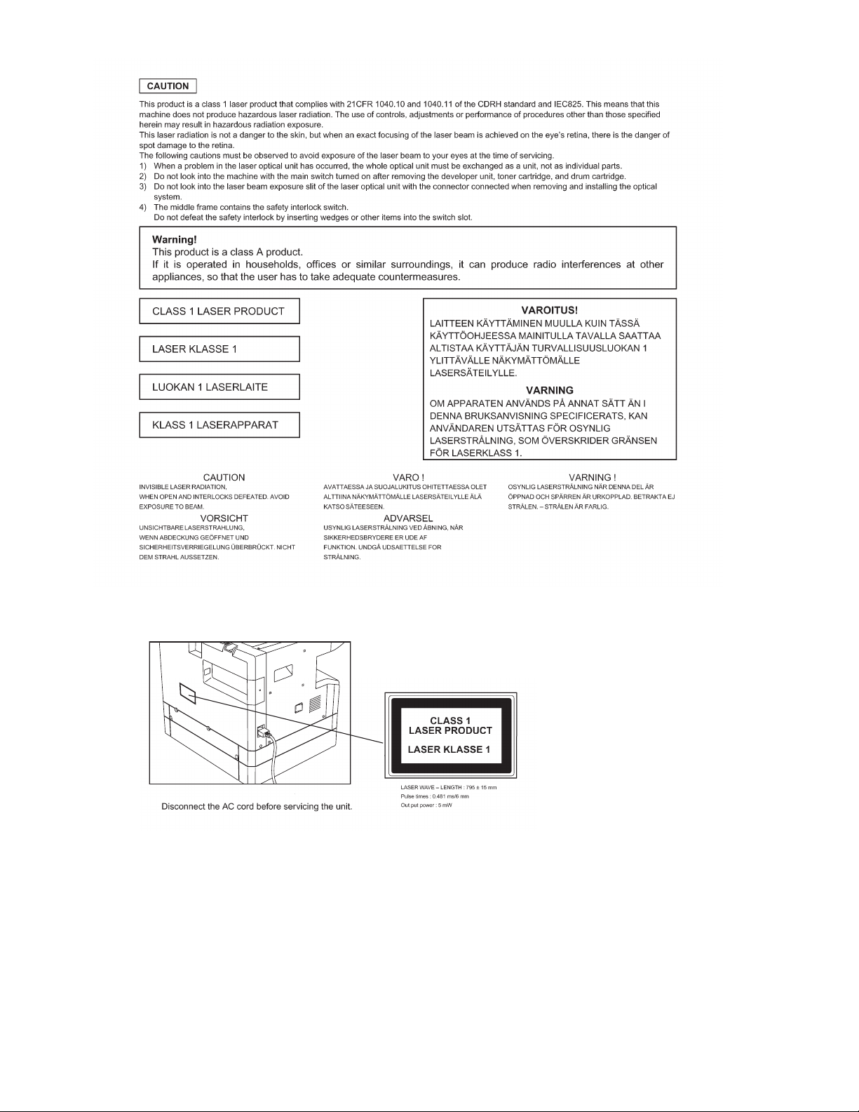
Pictogram
The label ( ) in the fusing area of the machine indicates the
following:
: Caution, risk of danger
: Caution, hot surface
•poorly ventilated
A. Warning for servicing
•The fusing area is hot. Exercise care in this area when removing misfed
paper.
•Do not look directly at the light source. Doing so may damage your eyes.
B. Cautions for servicing
•Do not switch the machine rapidly on and off. After turning the machine
off, wait 10 to 15 seconds before turning it back on.
•Machine power must be turned off before installing any supplies.
•Place the machine on a firm, level surface.
•Do not install the machine in a humid or dusty location.
•When the machine is not used for a long time, for example, during
prolonged holidays, turn the power switch off and remove the power
cord from the outlet.
•When moving the machine, be sure to turn the power switch off and
remove the power cord from the outlet.
•Do not cover the machine with a dust cover, cloth or plastic film while the
power is on. Doing so may prevent heat dissipation, damaging the
machine.
•Use of controls or adjustments or performance of procedures other than
those specified herein may result in hazardous laser radiation
exposure.
•The socket-outlet shall be installed near the machine and shall be easily
accessible.
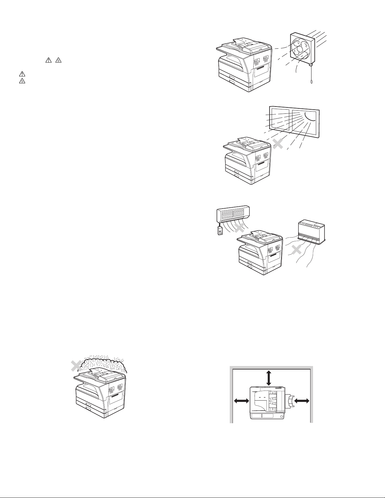
C. Note for installation place
Improper installation may damage the machine. Please note the
following during initial installation and whenever the machine is moved.
Caution : If the machine is moved from a cool place to a warm place,
condensation may form inside the machine. Operation in this
condition will cause poor copy quality and malfunctions. Leave
the machine at room temperature for at least 2 hours before
use.
Do not install your machine in areas that are:
•damp, humid, or very dusty
•exposed to direct sunlight
•subject to extreme temperature or humidity changes, e.g., near an air
conditioner or heater.
The machine should be installed near an accessible power outlet for
easy connection and disconnection.
Be sure to connect the power cord only to a power outlet that meets the
specified voltage and current requirements. Also make certain the outlet
is properly grounded.
Note : Connect the machine to a power outlet which is not used for other
electric appliances. If a lighting fixture is connected to the same
outlet, the light may flicker.
Be sure to allow the required space around the machine for servicing
and proper ventilation.
20 cm (8
"
)
AR-5520 GENERAL 1-1
20 cm
(8
"
)
20 cm
(8
"
)
Page 5
[2] CONFIGURATION
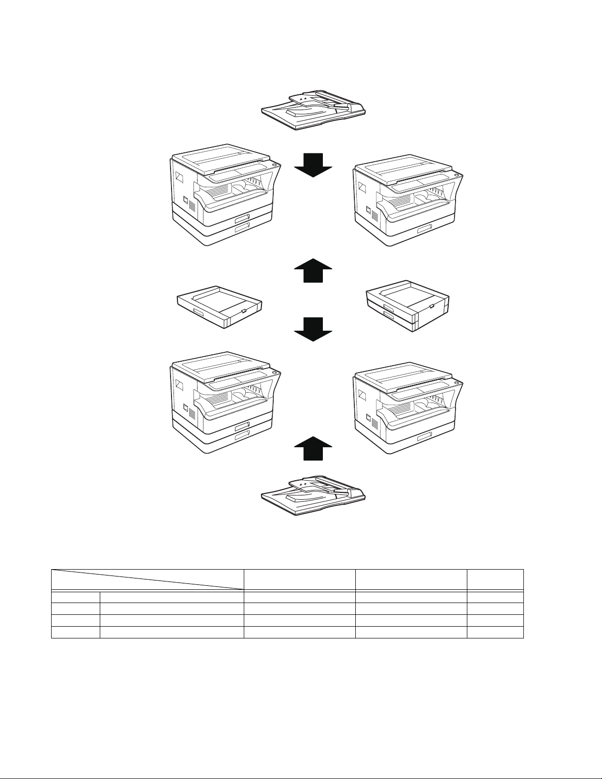
1. System Configurations
AR-5520/AR-5520S AR-5516/AR-5516S
AR-SP10
AR-D34
AR-5520D AR-5516D
Model
Option
AR-RP10 Duplex document auto feeder (RSPF)
AR-SP10 Document auto feeder (SPF)
AR-D34 1-stage paper feed unit
AR-D35 2-stage paper feed unit
O
:Option installation enable X: Option installation disable
AR-RP10
AR-5520 / AR-5520S
AR-5516 /AR-5516S
XO
OX
OO
OO
AR-D35
AR-5520D
AR-5516D
Remark
AR-5520 CONFIGURATION 2-1
Page 6

[3] SPECIFICATIONS
1. Copy mode
A. Type
Type Desk-top
Paper exit Wing less
B. Machine composition
AR-5516 / AR-5516S / AR-5516D 16-CPM multi function model
AR-5520 / AR-5520S / AR-5520D 20-CPM multi function model
(1) Option
Machine Model
250 sheets paper feed unit AR-D34
250 sheets x 2 paper feed unit AR-D35
SPF AR-SP10 AR-5520/ AR-5520S
AR-5516 /AR-5516S
RSPF AR-RP10 AR-5520D/ AR-5516D
C. Copy speed
(1) Engine speed (ppm)
Paper size
A4/ 8.5”x11” 20ppm 16ppm
A4R 14ppm 12ppm
8.5”x11”R 15ppm 12ppm
A5/ 5.5”x8.5” 20ppm 16ppm
B5/ 16K 20ppm 16ppm
B5R 16ppm 14ppm
16KR 15ppm 14ppm
8.5x13” 12ppm 11ppm
B4/ 8.5”x14 12ppm 10ppm
A3 11ppm 9ppm
11”x17” 10ppm 9ppm
8K 11ppm 10ppm
AR-5520 / AR-5520S
AR-5520D
(2) Document replacement speed (Copy mode)
Copy mode
S to S 20cpm (100%) 16cpm (100%)
S to D 9cpm (45%) 9cpm (56%)
D to D 8cpm (40%) 8cpm (50%)
S to S : Tray1 A4/8.5”X11” document 11 sheets (11 pages), copy 1 set
S to D : Tray1 A4/8.5”X11” document 22 sheets (22 pages), copy 1 set
D to D : Tray1 A4/8.5”X11” document 11 sheets (22 pages), copy 1 set
AR-5520 / AR-5520S
AR-5520D
(3) Job efficiency
Copy mode
S to S 19cpm (95%) 15cpm (94%)
S to D 11cpm (55%) 10cpm (63%)
D to D 10cpm (50%) 10cpm (63%)
S to S : Tray1 A4/8.5”X11” document 10 sheets (10 pages), copy 5 sets
S to D : Tray1 A4/8.5”X11” document 10 sheets (10 pages), copy 5 sets
D to D : Tray1 A4/8.5”X11” document 10 sheets (20 pages), copy 5 sets
AR-5520 / AR-5520S
AR-5520D
AR-5516 / AR-5516S
AR-5516D
AR-5516 / AR-5516S
AR-5516D
AR-5516 / AR-5516S
AR-5516D
(4) First copy time
Tr ay Content
1st tray 7.2 sec or less
2nd tray 8.5 sec or less
3rd tray 9.5 sec or less
4th tray 10.5 sec or less
Bypass tray 7.5 sec or less
600x300dpi, AE mode, A4/Letter, single surface copy with OC, in polygon
ready state
D. Document
Max. document size A3, 11" X 17"
Document reference position Left side center
Detection (Platen) None
E. Paper feed
(1) Paper feed section details
Paper capacity 250
Paper size detection No
Paper type setting No No No
Paper size changing method The paper guide is set by the user.
Paper when shipping AB series A4 A4 Size setting Inch series
Remaining paper quantity
detection
Item 1st tray 2nd tray
sheets
8 1/2” x11” 8 1/2” x11”
Only empty detection available
250
sheets
(Paper size is set with
the system setting.)
(2) Feedable paper
Paper size 1st tray 2nd tray
A3 297x420 Ye s Ye s Ye s
B4 257x364 Ye s Ye s Ye s
A4 297x210 Ye s Ye s Ye s
A4-R 210x297 Ye s Ye s Ye s
B5 257x182 Ye s Ye s Ye s
B5R 182x257 Ye s Ye s Ye s
A5 210x148.5 Ye s N/A Yes
A5R 148.5x210 N/A N/A Ye s
A6R 105x148.5 N/A N/A Ye s
B6R 128.5x182 N/A N/A Ye s
Ledger 11 x 17 in 279.4x431.8 Ye s Ye s Ye s
Legal 8.5x14in. 215.9x355.6 Yes Ye s Ye s
Foolscap 8.5 x 13 in 215.9x330.2 Yes Ye s Ye s
Letter 11x8.5in 279.4x215.9 Yes Ye s Ye s
Letter-R 8.5x11in 215.9x279.4 Yes Ye s Ye s
Executive-R 7.25x10.5in. 184.2x266.7 N/A N/A Ye s
Invoice 8.5x5.5 in. 215.9x139.7 Ye s N/A Ye s
Invoice-R 5.5x8.5 in 139.7x215.9 N/A N/A Ye s
8K 270x390 Ye s Ye s Ye s
16K 270x195 Ye s Ye s Ye s
16KR 195x270 Ye s Ye s Ye s
COM10 104.8x241.3 N/A N/A Ye s
COM9 98.4x225.4 N/A N/A Ye s
C5 162x229 N/A N/A Ye s
DL 110x220 N/A N/A Ye s
Postcard 100x148 N/A N/A Ye s
Return postcard 200x148 N/A N/A Ye s
Long format No. 3 120.1x235 N/A N/A Ye s
Monarch 98.4x190.5 N/A N/A Ye s
Western format No. 2 114x162 N/A N/A Ye s
Western format No. 4 105x235 N/A N/A Ye s
Bypass tray
100 sheets
(Heavy
paper setting
is enabled.)
-
Bypass
tray
AR-5520 SPECIFICATIONS 3-1
Page 7
(3)Types of feedable paper
Types of paper 1st tray 2nd tray Bypass tray
Thin paper
Plain paper
Heavy paper
Heavy paper
Heavy paper
Heavy paper
Envelope
Postcard N/A N/A Ye s
OHP film N/A N/A Ye s
Label sheet N/A N/A Ye s
Tab paper 20 N/A N/A Ye s
56-59g/m
15-15.9lbs
60-90g/m
16-24lbs
91-105g/m
16-24lbs
106-128g/m
24.1-33.5lbs
129-200g/m
33.6-53.2lbs
201-256g/m
53.3-68lbs
75-90g/m
20-24lbs
2
Ye s Ye s Ye s
2
Ye s Ye s
2
N/A N/A
2
N/A N/A
2
N/A N/A
2
N/A N/A N/A
2
N/A N/A Ye s
Ye s
(Multi paper feed enable)
Ye s
(Multi paper feed enable)
Ye s
(A4 or less)
(Multi paper feed enable)
Ye s
(A4 or less)
(Only single paper feed)
F. Multi copy
Max. number of multi copy 999 sheets
G. Warm-up time
Warm-up time 45 sec
Pre-heat Available
Jam recovery Within 45 sec
H. Copy magnification ratio
Fixed
magnification
ratio
Zooming 25 ~ 400%
Independent
zooming(vertical)
Independent zooming
(horizontal)
AB system:
50,70,86,100,141,200%
Inch system:
50,64,78,100,129,200%
SPF/RSPF(50 ~ 200%)
Available (25 ~ 400%)
SPF/RSPF(50 ~ 200%)
Available (25 ~ 400%)
SPF/RSPF(50 ~ 200%)
I. Print density
Density mode Auto / Text / Photo
No. of manual
adjustment
Resolution Writing: 600 x 600dpi
Gradation Reading: 256 gradations
Toner save mode Set by the user program
5 steps (Text / Photo)
Reading: 600 (main) x 600 (sub) (PHOTO mode)
600 (main) x 300 (sub) (AUTO exposure
mode)
Writing: Binary
J. Void width
Void area Lead edge 1 ~ 4mm,
rear edge 4mm or less,
Total of both sides: 6mm or less
Image loss OC Same size 3.0mm or less
Enlargement 1.5mm or less
Reduction 6.0mm or less
SPF/RSPF Same size 4.0mm or less
Enlargement 3.0mm or less
Reduction 8.0mm or less
K. Auto duplex
Standard/
Option
Standard provision (AR-5520D / AR-5516D only)
(D→ D / D → S enable only when RSPF is installed)
Not available for AR-5520 / AR-5520S / AR-5516/ AR5516S
L. Paper exit / finishing
Paper exit section
capacity
Full detection None
Finishing None
Electronic sort
capacity
Offset function None
Staple function None
Face down 250 sheets
A4/ 8.5" x 11" standard document (6%
coverage) 160 sheets
M. Additional functions
AR-5520S
AR-5516S
APS O
AMS O
Auto tray
switching
Memory copy O
Rotation copy O
E-sort (Sorting
function)
E-sort (Grouping
function)
Rotation sort X
Prevention of sky
shot
Independent
zooming
1 set 2 copy O
Binding margin
Edge erase
Center erase
Black/white
reverse
2in1/4in1 X O
Offset X
Preheating O The conditions are set by the user program.
Auto shut-off O The conditions are set by the user program.
User
programming
Total counter O Supports Total counter and Copy counter.
Coin vendor
support
Auditor support O (Supports I/F only.)
Duplex X O
Toner save O (Set according to the destination)
Department
management
O : Available X : Not available
X
X O
Disable in enlargement copy or when SPF/RSPF is
used.
X
X
X
AR-5520
AR-5516
O
Single surface, A4, 6% document, Max.
160 sheets
X
O
Default AB series: 10mm (5, 10, 15, 20mm)
Inch series: 1/2 inch (1/4, 1/2, 3/4, 1 inch)
Default AB series: 10mm (5, 10, 15, 20mm)
Inch series: 1/2 inch (1/4, 1/2, 3/4, 2 inch)
Default AB series: 10mm (5, 10, 15, 20mm)
Inch series: 1/2 inch (1/4, 1/2, 3/4, 3 inch)
X
O
O (Supports I/F only.)
O (Copy: 20 Dept.)
AR-5520D
AR-5516D
O
O
O
O
AR-5520 SPECIFICATIONS 3-2
Page 8
N. Other specifications
Photoconductor type OPC (Organic Photo Conductor)
Photoconductor drum dia. 30mm
Copy lamp Cold cathode fluorescent lamp (CCFL)
Developing system Dry 2-component magnetic brush
Charging system Saw teeth charging
Transfer system (+) DC corotron
Separation system (-) DC corotron
Fusing system Heat roller
Cleaning system Contact blade
development
O. Package form
Body Body / Accessories
P. External view
External dimensions
(With the bypass tray
closed)
Occupying area
(With the bypass tray
opened)
Weight
(Excluding
developer)
AR-5520S/AR-5520/
AR-5520D
590mm(W) x 550mm(D)
x 555mm(H) or less
883mm(W) x 550mm(D) or less
35.9Kg 30.9Kg
AR-5516S/AR-5516/
AR-5516D
590mm(W) x 550mm(D)
x 470mm(H) or less
T. Printing function
(1) Platform
Item Content
Support platform IBM PC/AT compatible machine
(2) Support OS
OS Support
Windows 95 X
Windows 98/Me X
Windows NT 4.0 SP5 X
Windows 2000 O
Windows XP 32 O
Windows XP 64 O (Web release only)
Windows Server 2003 X
Windows Vista 32 O
Windows Vista 64 O (Web release only)
Q. Power source
Voltage 100 - 127V 220 - 240V
Frequency 50/60Hz common
R. Power consumption
Max. power consumption 1200W
* EnergyStar conformity
Average power consumption in
operation
Power consumption when
standby
Energy consumption efficiency Less than 25W
Less than 550W
5W(Not include option)
S. Digital performance
Resolution Reading 600 x 600dpi (PHOTO mode)
Writing 600 x 600dpi
Gradation Reading 256 gradations
Writing Binary
Memory AR-5520S/5516S : 16MB
AR-5520/5516/5520D/5516D : 64MB
Hard disk None
600 x 300dpi (AUTO exposure mode)
AR-5520 SPECIFICATIONS 3-3
Page 9
(3) Printer driver function (SPLC)
Item SPLC
Common Default Button
MIMIC Ye s
Configuration
Main Copies 1-999
Paper Paper size A3/ A4/ A5/ A6/ B4/ B5/ B6/ Leger/
Advanced Image quality Draft/ Normal/ Photo
Watermark Watermark Top seclet/ Confidential/ Draft/
Input Tray Options One Tray/ Two Tray/ Three Tray/
Set
Paper
Tr ay
Source
Status
Set Paper
size
ROPM On/Off (The AR-5520S/5516S are
Status window Button
About Button
Collate On/ Off
N-UP printing 1/ 2/ 4 /6 up
User settings Button
Fit to paper size On/Off
Image orientation Portrait/ Landscape/ Rotate 180
Paper selection Auto select/ Tray1/ Tray2/ Bypass
Text to Black, Vector
to Black
Text Ye s
Size [6] - [300]
Angle [-90] - [90]
Grayscale [0] - [255]
Edit font Ye s
On first page only On/Off
Center Button
Position X: [-50] - [50]
Four Tray
Tray1/ Tray2/ Bypass Tray
Not set/ A3/ A4-R/ A5-R/ A6-R/ B4/
B5-R/ B6-R/ Leger/ Letter-R/
Legal/ Executive-R/ Invoice-R/
Foolscap/ Folio/ Com10/ DL/ C5/
8k/ 16k-R/ Custom paper
out of target.)
Letter/ Legal/ Executive/ Invoice/
Foolscap/ Folio/ Com10/ DL/ C5/
8k/ 16k/ Custom paper
- Custom paper:
Width [100.0] -[297.0]
[3.94”] -[11.69”]
Length [148.0] -[431.8]
[5.83”] - [17.00”]
- Milimeters/ Inches
A3/ A4/ A5/ A6/ B4/ B5/ B6/ Leger/
Letter/ Legal/ Executive/ Invoice/
Foolscap/ Folio/ Com10/ DL/ C5/
8k/ 16k
degrees
Tr ay
On/Off
Original/ Copy
Y: [-50] - [50]
U. Scanner function (Except for AR-5520/AR-5516)
Ty pe Flat bed scanner
Scan system Document table/document feed unit
Light source Yellow + Green CCFL
Resolution
Document Sheet/Book
Effective scan range
Scan speed
Input data 1bit or 12bit
Output data 1bit or 8bit
Scan color Black & white / binary / Gray scale
Protocol TWAIN / WIA(XP only) * / STI
Interface USB2.0 (High speed mode, full speed mode)
Scanner utility Button Manager
Drop-out color No
Scanner button Provided (6)
Supported OS
Void area
WHQL support No
Binary: 600 x 600 dpi
Gray scale: 300 x 300 dpi
OC/SPF/RSPF:
about 297(length) x 431(width) mm
OC/SPF/R-SPF:
0.962msec/line(300 dpi)
USB connection:Windows 2000/XP/VISTA
network connection:Windows 2000/XP/VISTA
Lead edge/rear edge (2.5mm) on the driver
side Left/right: 3.0mm
AR-5520 SPECIFICATIONS 3-4
Page 10
[4] CONSUMABLE PARTS
1.Supply system table
A. USA/Canada/South and Central America(100V series)
AR-5516/AR-5520D
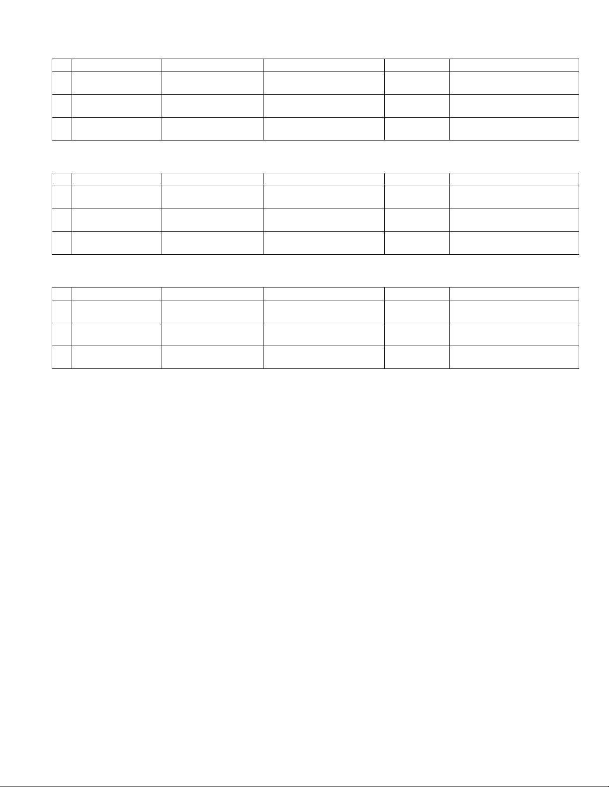
No. Name Product name Content Life Remark
1 Toner cartridge(Black) AR-020MT
(AR-020NT x 10)
2 Developer AR-205MD
(AR-205ND x 10)
3 Drum KIT AR-205DR Drum
B. South and Central America(200V series)
AR-5516/AR-5520D
No. Name Product name Content Life Remark
1 Toner cartridge(Black) AR-020LT
(AR-020T x 10)
2 Developer AR-205LD
(AR-205DV x 10)
3 Drum KIT AR-205DM Drum
C. Brazil
AR-5516/AR-5520D
No. Name Product name Content Life Remark
1 Toner cartridge(Black) AR-020MTB
(AR-020NTB x 10)
2 Developer AR-205MD
(AR-205ND x 10)
3 Drum KIT AR-205DR Drum
Toner cartridge
(Toner:Net 537g With IC)
Developer
(Net 300g)
Drum fixing plate
Toner cartridge
(Toner:Net 537g With IC)
Developer
(Net 300g)
Drum fixing plate
Toner cartridge
(Toner:Net 537g With IC)
Developer
(Net 300g)
Drum fixing plate
x10 160K(16Kx10) Life setting by A4 6% document
x10 500K(50x10)
x1 x150K
x10 190K(19Kx10) Life setting by A4 6% document
(In a toner save mode)
x10 500K(50x10)
x1 x150K
x10 190K(19Kx10) Life setting by A4 6% document
(In a toner save mode)
x10 500K(50x10)
x1 x150K
D. Europe
AR-5516/AR-5516S/AR-5520/AR-5520S/AR-5520D
No. Name Product name Content Life Remark
1 Toner cartridge(Black) AR-020LT
(AR-020T x 10)
2 Developer AR-205LD
(AR-205DV x 10)
3 Drum KIT AR-205DM Drum
Toner cartridge
(Toner:Net 537g With IC)
Developer
(Net 300g)
Drum fixing plate
x10 160K(16Kx10) Life setting by A4 6% document
(In a toner save mode)
x10 500K(50x10)
x1 x150K
E. Australia/New Zealand
AR-5516/AR-5516D/AR-5520/AR-5520S/AR-5520D
No. Name Product name Content Life
1 Toner cartridge(Black) AR-020LT
(AR-020T x 10)
2 Developer AR-205LD
(AR-205DV x 10)
3 Drum KIT AR-205DM Drum
Toner cartridge
(Toner:Net 537g With IC)
Developer
(Net 300g)
Drum fixing plate x1x1
x10 190K(19Kx10) Life setting by A4 6% document
x10 500K(50x10)
(In a toner save mode)
50K
AR-5520 CONSUMABLE PARTS 4-1
Page 11
F. Middle East/Africa/Israel/Philippine/Other Distributor
AR-5516/AR-5516S/AR-5516D/AR-5520/AR-5520S/AR-5520D
No. Name Product name Content Life Remark
1 Toner cartridge(Black) AR-021ET
(AR-021FT x 10)
2 Developer AR-205CD
(AR-205SD x 10)
3 Drum KIT AR-205DR Drum
Toner cartridge
(Toner:Net 537g With IC)
Developer
(Net 300g)
Drum fixing plate
x10 190K(19Kx10) Life setting by A4 6% document
x10 500K(50x10)
x1
50K
x1
(In a toner save mode)
G. Taiwan
AR-5516/AR-5516S/AR-5516D/AR-5520/AR-5520S/AR-5520D
No. Name Product name Content Life Remark
1 Toner cartridge(Black) AR-021ET
(AR-021FT x 10)
2 Developer AR-205CD
(AR-205SD x 10)
3 Drum KIT AR-205DR Drum
Toner cartridge
(Toner:Net 537g With IC)
Developer
(Net 300g)
Drum fixing plate x1x1
x10 160K(16Kx10) Life setting by A4 6% document
x10 500K(50x10)
50K
H. Asia(Except the above)
AR-5516/AR-5516S/AR-5516D/AR-5520/AR-5520S/AR-5520D
No. Name Product name Content Life Remark
1 Toner cartridge(Black) AR-020CT
(AR-020ST x 10)
2 Developer AR-205CD
(AR-205SD x 10)
3 Drum KIT AR-205DR Drum
Toner cartridge
(Toner:Net 537g With IC) x10
Developer
(Net 300g)
Drum fixing plate x1x1
x10 500K(50x10)
190K(19Kx10) Life setting by A4 6% document
(In a toner save mode)
50K
AR-5520 CONSUMABLE PARTS 4-2
Page 12
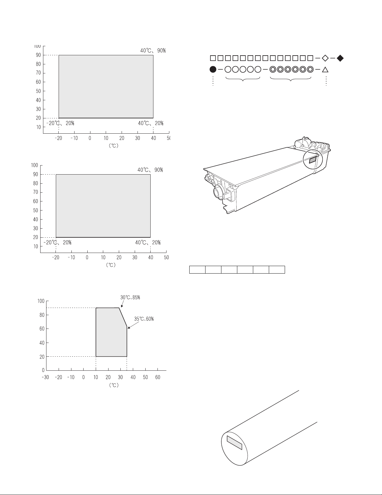
2. Environmental conditions
A. Transport conditions
(1) Transport conditions
3. Production number identification
<Toner cartridge>
The label on the toner cartridge shows the date of production.
Humidity (%)
(2) Storage conditions
Humidity (%)
Temperature
Temperature
Ver.No.Production
place
Serial
number
Year/
Month/
Day
<Drum cartridge>
The lot number, printed on the front side flange, is composed of 6 digits,
each digit showing the following content:
123456
B. Use conditions
Use environment
conditions
Humidity (%)
Temperature
C. Life(packed conditions)
Photoconductor drum (36 months from the production month)
Developer, toner (24 months from the production month)
1 Alphabet
Indicates the model conformity code. A for this model.
2 Number
Indicates the end digit of the production year.
3 Number or X, Y, Z
Indicates the month of packing.
X stands for October, Y November, and Z December.
4/5 Number
Indicates the day of the month of packing.
6 Alphabet
Indicates the production factory. "A" for Nara Plant, “C“ for
SOCC
AR-5520 CONSUMABLE PARTS 4-3
Page 13
[5] EXTERNAL VIEWS AND INTERNAL STRUCTURES
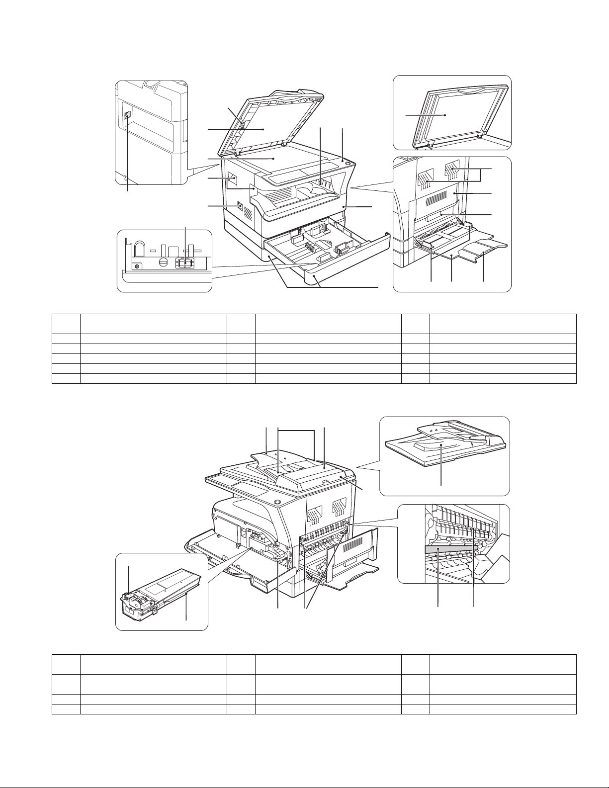
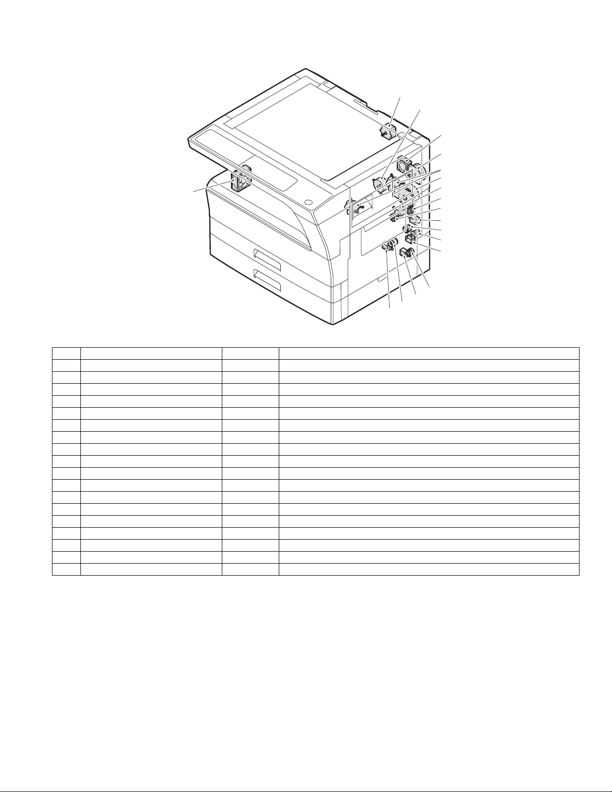
1. Appearance
1
7
2
3
4
16
5
15
6
8
9
2
4
10
11
13 14
12
1 Glass cleaner
(when the SPF/RSPF is installed)
4 Handles 5 Power switch 6 Operation panel
7 Paper output tray 8 Front cover 9 Paper trays
10 Side cover 11 Side cover handle 12 Bypass tray guides
13 Bypass tray 14 Bypass tray extension 15 Charger cleaner
16 USB 2.0 connector
2 Document feeder cover (when the SPF/
RSPF is installed) /document cover
3 Document glass
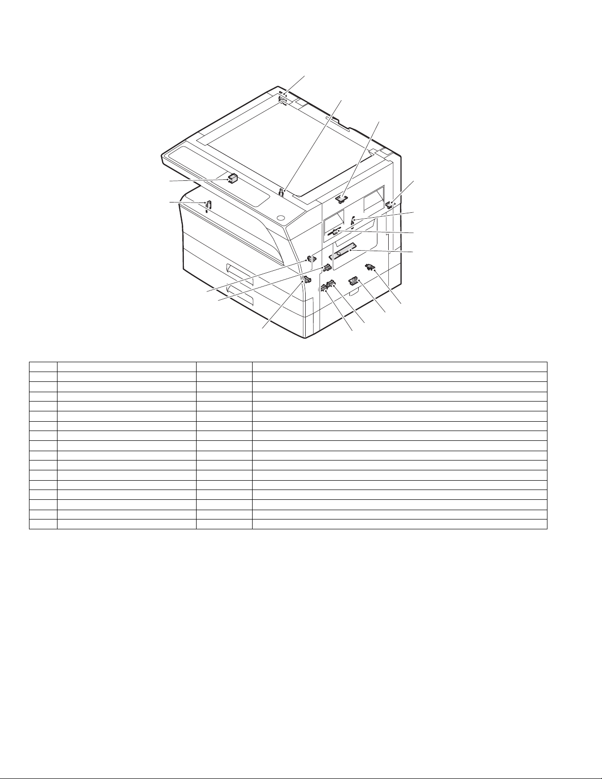
2. Internal
18
22
1917
20
21
24 25
2726
23
17 Document feeder tray
(when the SPF/RSPF is installed)
20 Right side cover
(when the SPF/RSPF is installed)
23 Toner cartridge 24 Roller rotating knob 25 Fusing unit release levers
26 Photoconductive drum 27 Fusing unit paper guide
AR-5520 EXTERNAL VIEWS AND INTERNAL STRUCTURES 5-1
18 Original guides
(when the SPF/RSPF is installed)
21 Exit area
(when the SPF/RSPF is installed)
19 Feeding roller cover
(when the SPF/RSPF is installed)
22 Toner cartridge lock release lever
Page 14
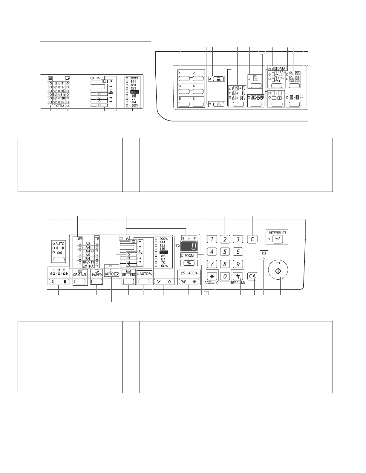
3. Operation Section
The indications of the operation panel may differ
depending on the country and the region.
The example of a display of inch series.
14
13
1 SCAN MENU key
(Except AR-5516S/AR-5520S)
4 ORIGINAL TO COPY key/indicators
(Except AR-5516/AR-5520/AR-5516S/
AR-5520S)
7 ERASE key / indicators
(Except AR-5516S/AR-5520S)
10 2 IN 1 / 4 IN 1 key / indicators
(Except AR-5516S/AR-5520S)
12
13
15
14
1
26
27
2 SCAN key / indicator
(Except AR-5516S/AR-5520S)
5 XY-ZOOM key / indicator 6 DUAL PAGE COPY key / indicator
8 ORIGINAL DATA indicator 9 SORT/GROUP key / indicators
11 MARGIN SHIFT key / indicator
(Except AR-5516S/AR-5520S)
16 17
15
2 3 4 5
3 ON LINE key/indicator
18
6 7
8
(Except AR-5516S/AR-5520S)
19
20
9
10
11
21 22
12 AUTO/TEXT/PHOTO key / indicators 13 ORIGINAL key / ORIGINAL SIZE
15 Paper feed location / misfeed location
indicators
18 Numeric keys 19 CLEAR key 20 INTERRUPT key / indicator
21 Light and Dark keys / indicators 22 PAPER SELECT key 23 AUTO PAPER SELECT indicator
24 TRAY SETTING key 25 AUTO IMAGE key / indicator 26 SPF/RSPF indicator
27 PRESET RATIO selector keys /
indicators
30 ZOOM indicator 31 Audit clear key 32 READ-END key
33 CLEAR ALL key 34 POWER SAVE indicator 35 START key / indicator
AR-5520 EXTERNAL VIEWS AND INTERNAL STRUCTURES 5-2
24 25 26
23
When there are two or more paper trays
indicators
16 Alarm indicators 17 Display
28 Zoom keys 29 Copy ratio display key
27
28
29
30 31 35343332
14 PAPER SIZE indicators
(when the SPF/RSPF is installed)
Page 15
4. Motor, solenoid, clutch
17
16
1
15
14
2
18
3
4
5
6
7
8
9
10
11
12
13
No.
1 Mirror motor MRM Drives the optical mirror base (scanner unit).
2 Toner motor TM Toner supply
3 Duplex motor DPX Switchback operation and paper exit motor in duplex.
4 Cooling fan motor CFM Cools the inside of the machine.
5 Main motor MM Drives the machine.
6 1st tray paper feed clutch CPFC1 Drive the pick up roller
7 PS clutch RRC Drives the resist roller
8 Paper feed solenoid CPSOL1 Solenoid for paper feed from tray
9 Resist roller solenoid RRS Resist roller rotation control solenoid
10 Bypass tray paper transport clutch MPTC Drives the bypass tray paper transport roller.
11 Bypass tray paper feed clutch MPFC Drives the bypass tray paper feed roller.
12 Bypass tray paper feed solenoid MPFS Bypass tray paper feed solenoid
13 2nd tray transport clutch CPFC2 Drives the 2nd tray transport roller.
14 2nd tray transport solenoid FSOL1 2nd tray transport solenoid
15 2nd tray paper feed clutch CPFC1 Drives the 2nd tray paper feed roller.
16 2nd tray paper feed solenoid PSOL2 2nd tray transport solenoid
17 Exhaust fan motor VFM Cools the inside of the machine.
18 Cooling fan motor CFM Cools the inside of the machine.
Name
Code
Function operation
AR-5520 EXTERNAL VIEWS AND INTERNAL STRUCTURES 5-3
Page 16
5. Sensor, switch
1
2
3
16
4
15
5
6
7
14
13
8
9
12
No. Name Code Function operation
1 Mirror home position sensor MHPS Detects the mirror (scanner unit) home position.
2 Side door switch DSWR Side door open detection
3 Paper exit sensor (paper exit side) POD1 Detects paper exit.
4 Paper exit sensor (DUP side) PDPX Paper transport detection
5 Thermistor RTH Fusing section temperature detection
6 Thermostat Fusing section abnormally high temperature detection
7 Toner density sensor TCS Toner quantity detection
8 2nd tray detection switch 2nd tray detection
9 Bypass tray sensor MPED Bypass tray transport detection
10 2nd tray door open/close sensor DRS2 2nd tray door open/close detection
11 2nd tray door paper pass sensor PPD2 2nd tray paper entry detection
12 2nd tray paper empty sensor CSS2 2nd tray paper empty detection
13 Paper in sensor PIN Paper transport detection
14 Tray empty Tray paper entry detection
15 Front cover SW Front cover open detection
16 Power switch MAIN SW Turns ON/OFF the main power source.
10
11
AR-5520 EXTERNAL VIEWS AND INTERNAL STRUCTURES 5-4
Page 17
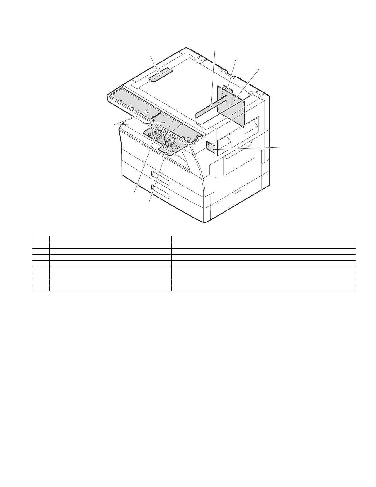
6. PWB unit
2
1
8
3
7
4
6
5
No. Name Function operation
1 Copy lamp Inverter PWB Copy lamp control
2 CCD sensor PWB Image scanning
3 Main control PWB Main control PWB
4 2nd tray PWB 2nd tray control
5 High voltage PWB High voltage control
6Power PWB AC power input/DC power control
7 Operation main PWB Operation panel input/Display, operation panel section control
8USB I/F PWB Connect a USB device
AR-5520 EXTERNAL VIEWS AND INTERNAL STRUCTURES 5-5
Page 18
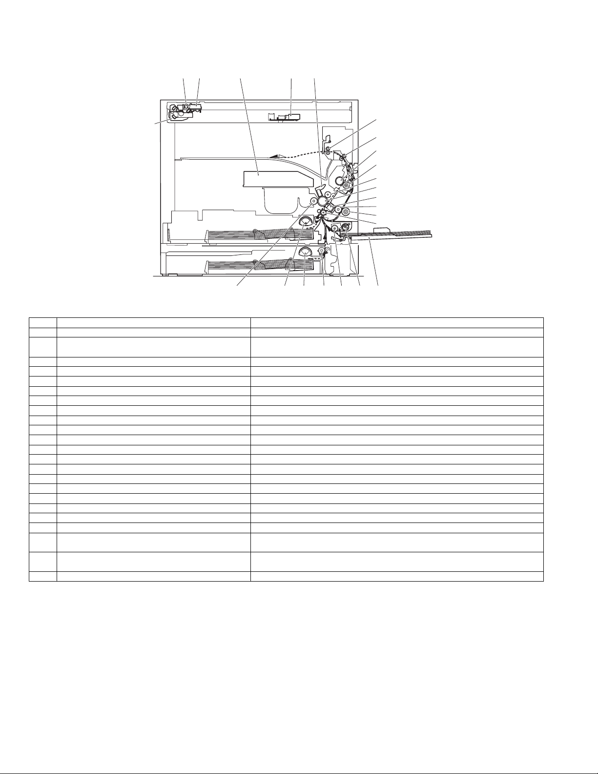
7. Cross sectional view
18
1 4
2
53
6
7
8
9
10
11
12
13
14
15
16171920212223
No. Name Function/Operation
1 Copy lamp Image radiation lamp
2 Copy lamp unit Operates in synchronization with No. 2/3 mirror unit to radiate documents
3 LSU unit Converts image signals into laser beams to write on the drum.
4 Lens unit Reads images with the lens and the CCD.
5 MC holder unit Supplies negative charges evenly on the drum.
6 Paper exit roller Used to discharge paper.
7 Transport roller Used to transport paper.
8 Upper heat roller Fuses toner on paper (with the teflon roller).
9 Lower heat roller Fuses toner on paper (with the silicon rubber roller).
10 Waste toner transport roller Transports waste toner to the waste toner box.
11 Drum unit Forms images.
12 Transfer charger unit Transfer images (on the drum) onto paper.
13 DUP follower roller
14 Duplex transport roller Transports paper for duplex .
15 Resist roller Takes synchronization between the paper lead edge and the image lead edge.
16 Bypass tray Bypass tray
17 Bypass tray paper pick up roller Picks up paper in bypass tray.
18 No. 2/3 mirror unit Reflects the images from the copy lamp unit to the lens unit.
19 Bypass tray transport roller Transports paper from the bypass tray.
20 2nd tray paper transport roller Transports paper from the 2nd tray.
21 2nd tray paper pick up roller
(semi-circular roller)
22 1st tray paper feed roller
(semi-circular roller)
23 MG roller Puts toner on the OPC drum.
sequentially.
Picks up paper from the 2nd tray.
Picks up paper from the 1st tray.
AR-5520 EXTERNAL VIEWS AND INTERNAL STRUCTURES 5-6
Page 19
[6]ADJUSTMENTS
1.Adjustment item list
Section Adjustment item Adjustment procedure/SIM No.
A Process
section
B Mechanism
section
C Image density
adjustment
(1) Developing doctor gap adjustment Developing doctor gap adjustment
(2) MG roller main pole position adjustment MG roller main pole position adjustment
(3) Developing bias voltage check
(4) Main charger voltage check
(1) Image position adjustment SIM-50
(2) Main scanning direction (FR direction) distortion balance
adjustment
No. 2/3 mirror base unit installing position adjustment
Copy lamp unit installing position adjustment
(3) Main scanning direction (FR direction) distortion adjustment Rail height adjustment
(4) Sub scanning direction (scanning direction) distortion
Winding pulley position adjustment
adjustment
(5) Main scanning direction (FR direction) magnification ratio
SIM 48-1
adjustment
(6) Sub scanning direction (scanning direction) magnification ratio
adjustment
OC mode in copying (SIM 48-1)
SPF mode in copying (SIM 48-5)
(7) Off center adjustment OC mode (SIM 50-12)
SPF mode (SIM 50-12)
(8) SPF white correction pixel position adjustment
required in an SPF model when replacing the lens unit)
(
SIM63-7
(1) Copy mode SIM 46-1
2.Copier adjustment
A.Process section
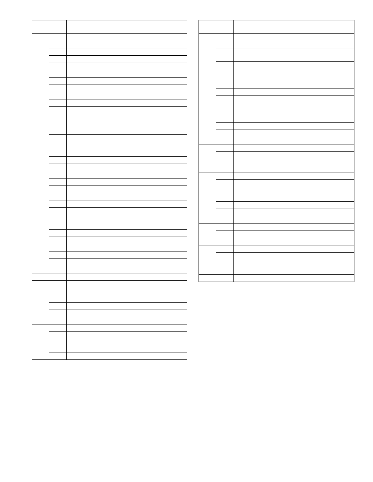
(1) Developing doctor gap adjustment
1) Loosen the developing doctor fixing screw A.
2) Insert a thickness gauge of 1.5mm to the three positions at 20mm
and 150mm from the both ends of the developing doctor as shown.
OO
OO
OO
3) Push the developing doctor in the arrow direction, and tighten the
developing doctor fixing screw. (Perform the same procedure for the
front and the rear frames.)
4) Check the clearance of the developing doctor. If it is within the
specified range, then fix the doctor fixing screw with screw lock.
* When inserting a thickness gauge, be careful not to scratch the
developing doctor and the MG roller.
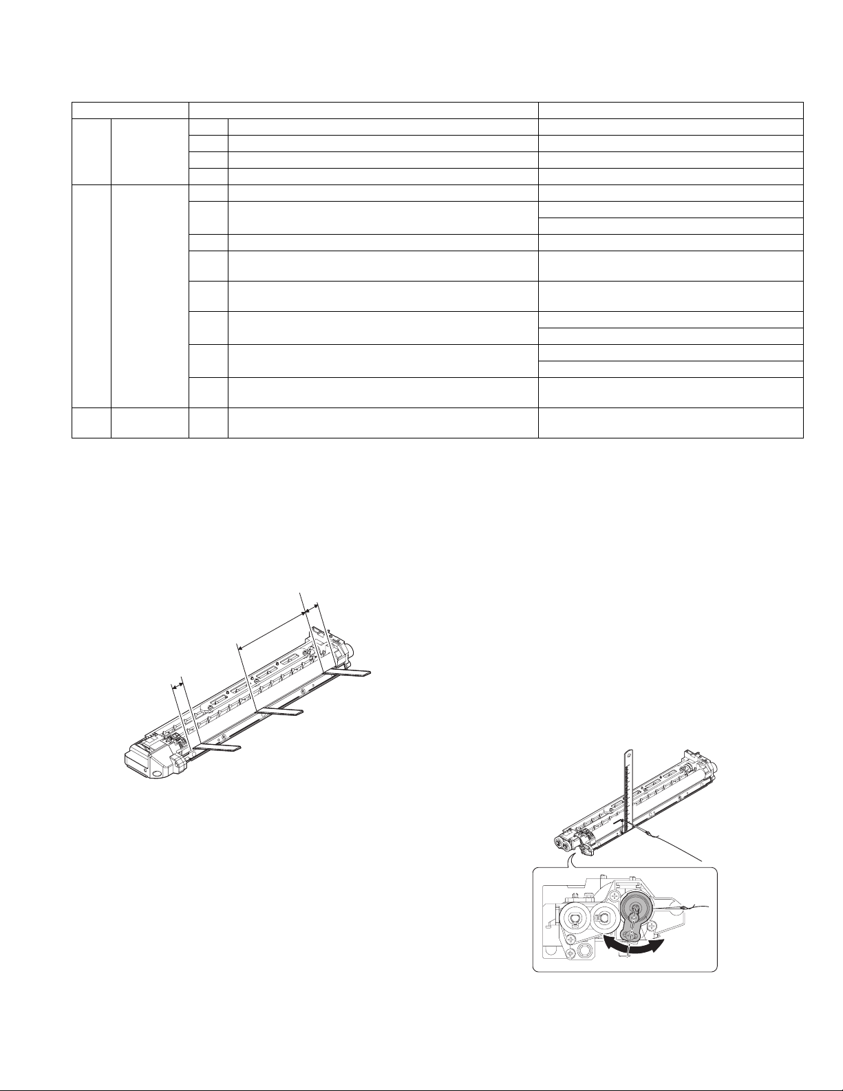
(2) MG roller main pole position adjustment
1) Remove and separate the waste toner box and put the developing
unit on a flat surface.
2) Tie a string to a needle or a pin.
3) Hold the string and bring the needle close to the MG roller
horizontally. (Do not use paper clip, which is too heavy to make a
correct adjustment.) (Put the developing unit horizontally for this
adjustment.)
4) Do not bring the needle into contact with the MG roller, but bring it to
a position 2 or 3mm apart from the MG roller. Mark the point on the
MG roller which is on the extension line from the needle tip.
5) Measure the distance from the marking position to the top of the
doctor plate of the developing unit to insure that it is 18mm.
If the distance is not within the specified range, loosen the fixing
screw A of the main pole adjustment plate, and move the adjustment
plate in the arrow direction to adjust.
<Adjustment specification>
Developing doctor gap
Both ends (20mm from the both ends) :
C (Center) (150mm from the both ends) :
+0.1
1.5 mm
- 0.15
+0.15
1.55 mm
- 0.2
AR-5520 ADJUSTMENT 6-1
Page 20
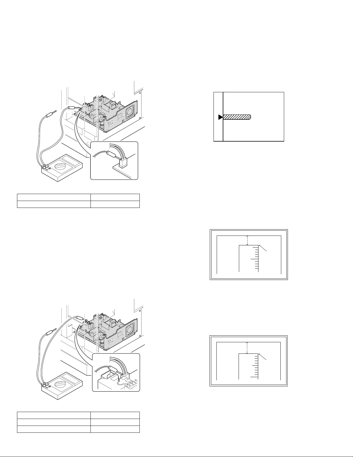
(3)Developing bias voltage check
Note:Use a digital multi-meter with an internal resistance of 10MΩ or
more.
1) Set the digital multi-meter range to DC700V.
2) Put the test rod of the digital multi-meter on the developing bias
voltage output check pin.
3) Turn on the power, execute SIM25-1.
<Specification>
Mode Specification
Developing bias voltage DC - 400±10V
(4) Grid bias voltage check
Note:Use a digital multi-meter with an internal resistance of 10MΩ or
more.
1) Set the digital multi-meter range to DC700V.
2) Put the test rod of the digital multi-meter on the grid bias voltage
output check pin.
3) Turn on the power.
(The voltage is outputted in the grid bias High output mode during
warming up, and in the grid bias Low output mode when warming up
is completed.)
B.Mechanism section
Note: If a jam error or paper empty occurs during copying in the
adjustment by the simulation, the image data are not saved, and
therefore recopying is required.
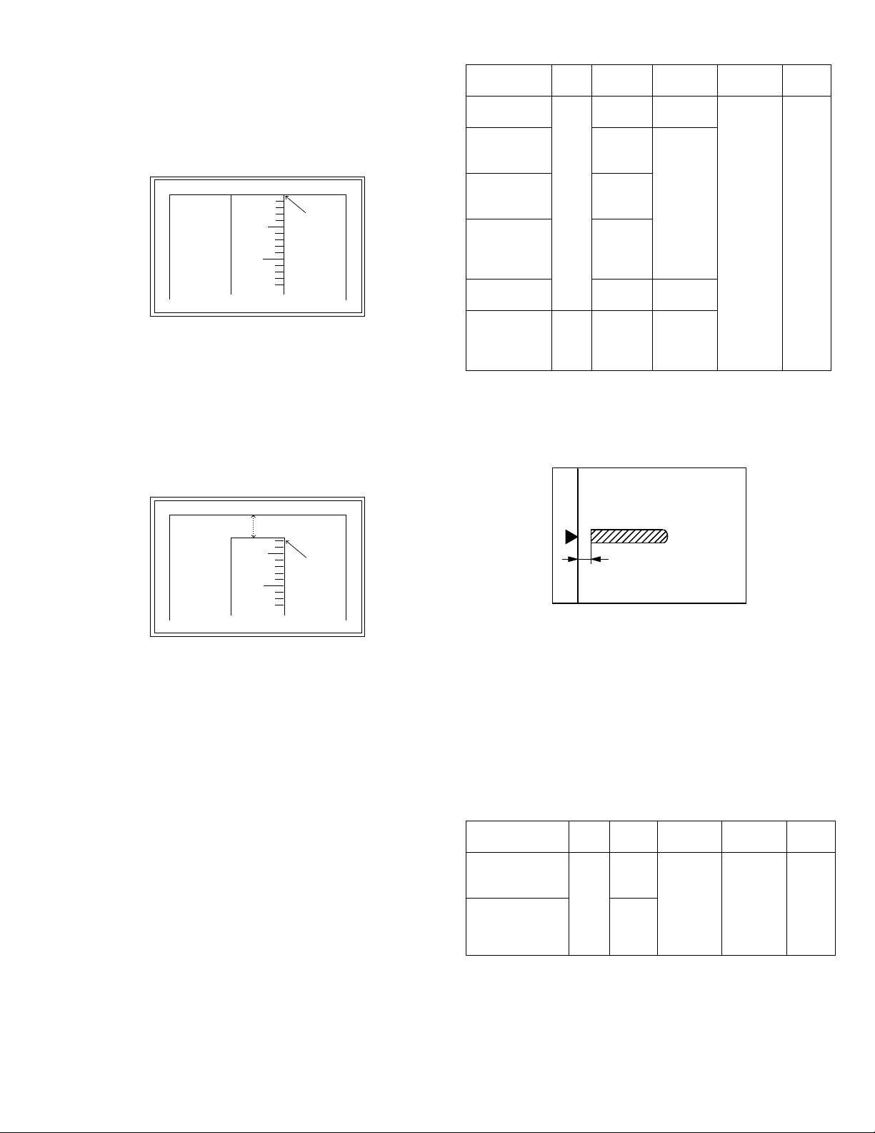
(1) Image position adjustment
a.OC image lead edge position adjustment (SIM 50-1)
Note:In advance to this adjustment, the sub scanning magnification ratio
adjustment must be performed.
1) Set a scale on the OC table as shown below.
2) Make a copy.
3) Check the copy output. If necessary, perform the following
adjustment procedures.
4) Execute SIM 50-1.
5) Set the OC lead edge position set value (PHOTO indicator ON) to [1]
The OC image scanning start position is shifted inside the document
edge.
6) Set the 1st tray lead edge void adjustment value (TEXT indicator
ON) * to [1]
The lead edge void becomes the minimum.
7) Set the 1st tray print start position value (AUTO, 1st tray indicator
ON) to [1] and make a copy.
The print start position is shifted inside the document edge.
5mm
5
4mm
10
*The dimension varies depending on the model.
8) Measure the image loss R of the copied image. Enter the set value
of the image scanning lead edge position (PHOTO indicator ON)
again.
•1 step of the set value corresponds to about 0.1mm shift.
•Calculate the set value from the formula below.
R/0.1(mm) = Image loss set value
<R: Image loss measurement value (mm)>
<Specification>
Mode Specification
Grid bias LOW DC - 380±8V
Grid bias HIGH DC - 525±10V
Example: 4/0.1 = 40 = about 40
Note:If the set value is not obtained from the above formula, perform the
fine adjustment.
AR-5520 ADJUSTMENT 6-2
5mm
5
10
* The scanning edge is set.
(A line may be printed by scanning the document edge.)
0mm
Page 21
9) Measure the distance H between the paper lead edge and the image
print start position. Set the image print start position set value
(AUTO, 1st tray indicator ON) again.
•1 step of the set value corresponds to about 0.1mm shift.
•Calculate the set value from the formula below.
H/0.1(mm) = Image print start position set value
<H: Print start position measurement value (mm)>
0mm
5
10
0mm
<Adjustment specification>
Adjustment
mode
OC image lead
edge position
1st tray print
start position
SIM LED Set
value
SIM
PHOTO R/0.1 Lead edge
50-1
AUTO
B/0.1
+
1st tray
2nd tray print
start position
Bypass tray
print start
position
AUTO
+
tray
2nd
AUTO
+
Bypass
tray
Lead edge void TEXT B/0.05
Spec
value
void:
1 - 4mm
Image loss:
3mm or
less
Set
range
1 ~ 99
*Fit the print edge with the paper edge, and perform the
lead edge adjustment.
Example: 5/0.1 = 50 = about 50
Note:If the set value is not obtained from the above formula, perform the
fine adjustment.
10) Set the lead edge void adjustment value (TEXT indicator ON)* again.
•1 step of the set value corresponds to about 0.1mm shift.
•Calculate the set value from the formula below.
B/0.05 (mm) = Lead edge void adjustment value
<B: Lead edge void (mm)>
2.5mm
5
10
2.5mm
Example: When setting the lead edge void to 2.5mm
:2.5 /0.05 = about 50
Note:If the set value is not obtained from the above formula, perform the
fine adjustment.
* 2nd tray lead edge void adjustment: Exposure display <<AUTO +
TEXT + PHOTO>>
Bypass tray lead edge void adjustment: (TEXT indicator and PHOTO
indicator ON)
<Duplex mode adjustment>
OC 2nd print surface (Auto duplex) lead edge position adjustment:
SIM50-19 <<PHOTO>>
* For the adjustment procedure, set to S → D mode before execution.
Note:Before performing the 2nd print surface lead edge position
adjustment and the lead edge void adjustment, be sure to perform
the 1st print surface lead edge position adjustment in advance, and
be sure to perform the 2nd print surface lead edge position
adjustment and then the lead edge void adjustment in this
sequence.
OC 2nd print
surface lead
SIM
50-19*
PHOTO 1 step:
0.1mm shift
edge position
adjustment
* (Set to S → D mode for before execution)
b.SPF image lead edge position adjustment (SIM50-6)
1) Set a scale on the OC table as shown below.
Note:Since the printed copy is used as a test chart, put the scale in
paralled with the edge lines.
2) Make a copy, Then use the copy output as an original to make an
SPF copy again.
3) Check the copy output. If necessary, perform the following
adjustment procedures.
4) Execute SIM 50-6.
5) Set the SPF lead edge position set value (AUTO indicator ON) so
that the same image is obtained as that obtained in the previous OC
image lead edge position adjustment.
<Adjustment specification>
Adjustment mode SIM LED Set value Spec value Set
range
SPF image lead
edge position
(1st print surface)
SIM
50-6
AUTO 1 step:
0.1mm shift
Lead edge
void:
1 - 4mm
1 ~ 99
(2nd print surface) TEXT
Image loss:
3mm or
less
AR-5520 ADJUSTMENT 6-3
Page 22
c.Rear edge void adjustment (SIM50-1, SIM50-19)
1) Set a scale as shown in the figure below.
A4(8.5" x 11")
Paper rear edge
2) Set the document size to A4 (8.5" x 11"), and make a copy at 100%.
3) If necessary, perform the following adjustment procedure.
Void amount (Standard value: 4mm or less)
Scale image
Paper rear edge
4) Execute SIM 50-1 and set the density mode to AUTO + TEXT +
PHOTO (Rear edge void).The currently set adjustment value is
displayed.
5) Enter the set value and press the [START] key. The correction value
is stored and a copy is made.
<Duplex mode adjustment>
* 1st print surface (auto duplex) rear edge void adjustment:
SIM50-19 <<AUTO>>
* 2nd print surface (auto duplex) rear edge void adjustment:
SIM50-19<<TEXT>>
*Set to S → D mode before execution.
Note:Before performing the 2nd print surface rear edge void adjustment,
be sure to perform the 2nd print surface lead edge position
adjustment. Never reverse the sequence.
<Adjustment specification>
Mode SIM LED Set value Specifi-
Rear edge void SIM
50-1
AUTO
+
1 step:
0.1mm shift
cation
4mm or
less
Set
range
1 ~ 99
TEXT
+
PHOTO
1st print
surface rear
SIM
50-19*
AUTO
edge void
2nd print
surface rear
SIM
50-19*
TEXT
edge void
<Duplex mode adjustment>
* 2nd print surface (auto duplex) off-center adjustment:
SIM50-10 (TEXT, 1st tray indicator)
<Adjustment specification>
Mode SIM LED Set value Specifi-
cation
Paper off
center
SIM
50-10
AUTO
+
Selected
Add 1:
0.1mm shift
to R side.
Single:
Center
±2.0mm
Set
range
1 ~ 99
tray ON
2nd print
surface off-
center
SIM
50-10
TEXT
+
1st tray
Reduce 1:
0.1mm shift
to L side.
Duplex:
Center
±2.5mm
e.Side edge void area adjustment (SIM26-43)
Note:Before performing this adjustment, be sure to check that the paper
off center adjustment (SIM 50-10) is completed.
1) Set a test chart (UKOG-0089CSZZ) on the document table.
2) Select a paper feed port and make two copies. Compare the 2nd
copy and the test chart. If necessary, perform the following
adjustment procedure.
* The 1st copy does not show the void. Be sure to check the 2nd copy.
3) Execute SIM 26-43 and set the density mode to AUTO(right edge
void) + TEXT (Left edge void).
The currently set adjustment value is displayed.
4) Enter the set value and press the [START] key. The correction value
is stored.
<Adjustment specification>
ode SIM LED Set value Specifi-
Left edge void SIM
26-43
AUTO
(right
1 step:
0.5mm shift
cation
0 ~ 10mm 1 ~ 99
Set
range
edge)
+
TEXT
(left edge)
* The void adjustment values on the right and the left must be the
same.
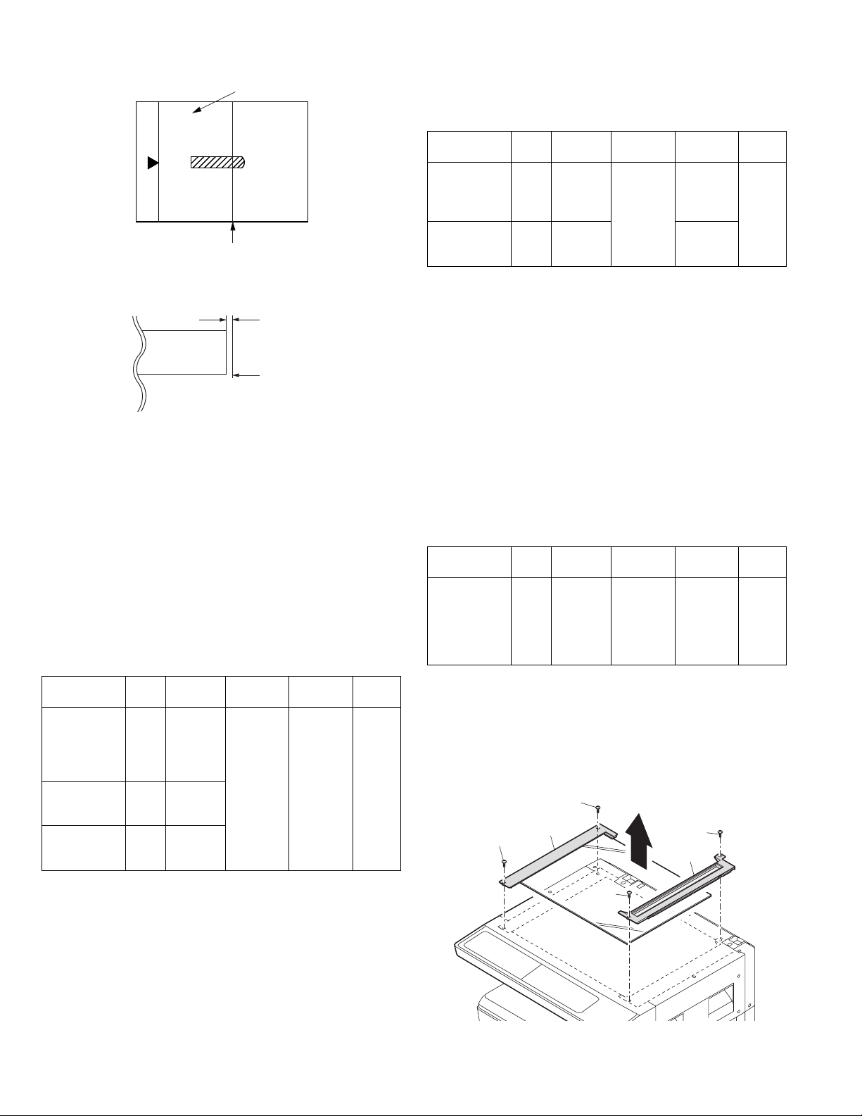
(2) Main scanning direction(FR direction) distortion balance
adjustment
1) Remove the OC glass and the right cabinet.
(1)
(1)
(2)
(3)
(4)
* Set to S → D mode before execution
d. Paper off center adjustment (SIM50-10)
1) Set a test chart (UKOG-0089CSZZ) on the document table.
2) Select a paper feed port and make a copy. Compare the copy and
the test chart. If necessary, perform the following adjustment
procedure.
3) Execute SIM 50-10. After completion of warm-up, shading is
performed and the currently set off center adjustment value of each
paper feed port is displayed.
4) Enter the set value and press the [START] key. The correction value
is stored and a copy is made.
AR-5520 ADJUSTMENT 6-4
(3)
Page 23
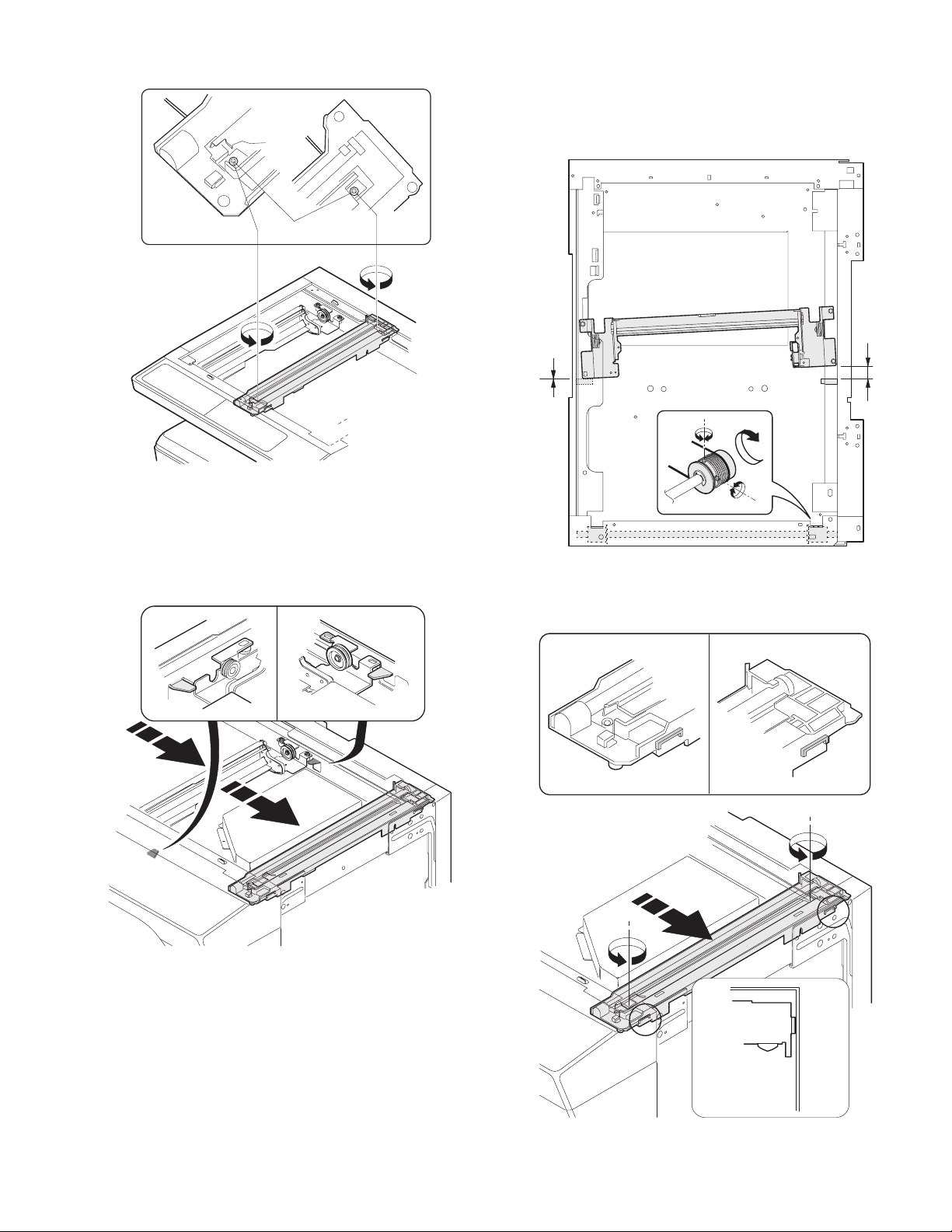
2) Loosen the copy lamp unit wire fixing screw.
Wire fixing screw
3) Manually turn the mirror base drive pulley and bring No. 2/3 mirror
base unit into contact with the positioning plate. At that time, if the
front frame side and the rear frame side of No. 2/3 mirror base unit
are brought into contact with the positioning plate at the same time,
the mirror base unit parallelism is proper. If one of them is in contact
with the positioning plate, perform the adjustment of 4).
4) Loosen the set screw of the scanner drive pulley which is not in
contact with No. 2/3 mirror base unit positioning plate.
5) Without moving the scanner drive pulley shaft, manually turn the
scanner drive pulley until the positioning plate is brought into contact
with No. 2/3 mirror base unit, then fix the scanner drive pulley.
6) Put No. 2/3 mirror base unit on the positioning plate again, push the
projections on the front frame side and the rear frame side of the
copy lamp unit to the corner frame, and tighten the wire fixing screw.
AR-5520 ADJUSTMENT 6-5
Page 24
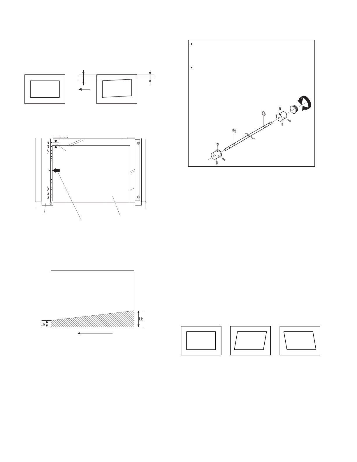
(3)Main scanning direction (FR direction) distortion
r
adjustment
This adjustment must be performed in the following cases:
•When the mirror base drive wire is replaced.
•When the lamp unit, or No. 2/3 mirror holder is replaced.
•When a copy as shown is made.
La
Paper exit
direction
Original
Copy
1) Set A3 (11" x 17") white paper on the original table as shown below.
Allow a little space.
Lb
4) Loosen the mirror base drive pulley fixing screw on the front frame
side or on the rear frame side.
When La < Lb
Turn the mirror base drive pulley on the front frame side in the
arrow direction A.
(Do not move the mirror base drive pulley shaft.)
When La > Lb
Turn the mirror base drive pulley on the front frame side in the
arrow direction A.
(Do not move the mirror base drive pulley shaft.)
Rear side
A
B
Front side
5)Tighten the mirror base drive pulley fixing screw.
Glass holding plate
Fit the paper edge and
the glass holding plate edge.
A3 (11" x 17") white pape
2) Open the original cover and make a normal (100%) copy.
3) Measure the width of the black background at the lead edge and at
the rear edge.
Paper exit direction
La: Lead edge black background width
Lb: Rear edge black background width
If the width (La) of the black background at the lead edge is equal that
(Lb) at the rear edge, there is no need to execute the following
procedures of 4) ~ 7).
<Adjustment specification>
La = Lb
6) Execute the main scanning direction (FR) distartion balance
adjustment previously described in 2) again.
(4) Sub scanning direction (scanning direction) distortion
adjustment
When there is no skew copy in the mirror base scanning direction and
there is no horizontal error (right angle to the scanning direction), the
adjustment can be made by adjusting the No. 2/3 mirror base unit rail
height.
Before performing this adjustment, be sure to perform the horizontal
image distortion adjustment in the laser scanner section.
This adjustment must be performed in the following cases:
•When the mirror base wire is replaced.
•When the copy lamp unit or No. 2/3 mirror unit is replaced.
•When the mirror unit rail is replaced or moved.
•When a following copy is made.
Original
Copy A Copy B
AR-5520 ADJUSTMENT 6-6
Page 25
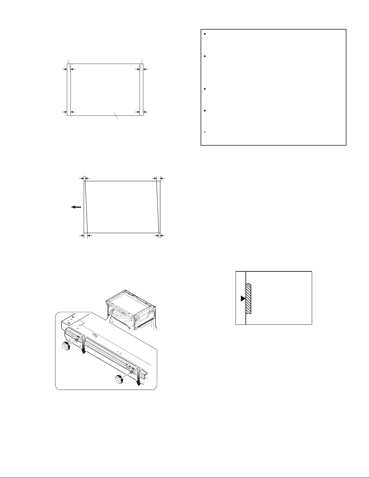
1) Making of a test sheet
Make test sheet by drawing parallel lines at 10mm from the both
ends of A3 (11" x 17") white paper as shown below. (These lines
must be correctly parallel to each other.)
When La > Lb
Shift the mirror base B rail upward by the half of the
difference of La - Lb.
Parallel line
10mm
10mm
White paper
Parallel line
10mm
10mm
2) Make a normal (100%) copy of the test sheet on A3 (11" x 17")
paper. (Fit the paper edge with the glass holding plate edge.)
3) Measure the distances (La, Lb, Lc, Ld) at the four corners as shown
below.
Paper exit
direction
La
Lb Ld
Lc
When La < Lb
Shift the mirror base B rail downward by the half of the
difference of Lb - La.
Example: When La = 12mm and Lb = 9mm, shift the mirror
base B rail upward by 1.5mm.
When Lc > Ld
Shift the mirror base B rail downward by the half of the
difference of Lc - Ld.
When Lc < Ld
Shift the mirror base B rail downward by the half of the
difference of Ld - Lc.
When moving the mirror base rail, hold the mirror base rail
with your hand.
<Adjustment specification>
La = Lb, Lc = Ld
5) After completion of adjustment, manually turn the mirror base drive
pulley, scan the mirror base A and mirror base B fully, and check that
the mirror bases are not in contact with each other.
* If the mirror base rail is moved extremely, the mirror base may be in
contact with the frame or the original glass. Be careful to avoid this.
(5) Main scanning direction (FR direction) magnification
ratio adjustment (SIM 48-1)
Note:Before performing this adjustment, be sure to check that the CCD
unit is properly installed.
When La = Lb and Lc = Ld, no need to perform the procedures 4) and 5).
4) Move the mirror base F rail position up and down (in the arrow
direction) to adjust.
Note:Do not adjust the rail on the rear side.
If the rail on the rear side is adjusted, a trouble may be caused.
Only the rail on the front side can be adjusted.
1) Put a scale on the original table as shown below.
2) Execute SIM 48-1.
3) After warm-up, shading is performed and the current set value of the
main scanning direction magnification ratio is displayed on the
display section in 2 digits.
4) Select the mode and press the [START] key again.
5) Manual correction mode (TEXT indicator ON)
Enter the set value and press the [START] key.
The set value is stored and a copy is made.
AR-5520 ADJUSTMENT 6-7
Page 26
<Adjustment specification>
Note: A judgment must be made with 200mm width, and must not be
made with 100mm width.
Mode Specification SIM Set value Set range
Main scanning
direction
magnification
ratio
At normal:
±1.0%
SIM 48-1 Add 1:0.1%
increase
Reduce 1:
0.1%
1 ~ 99
decrease
(6) Sub scanning direction (scanning direction)
magnification ratio adjustment (SIM 48-1, SIM 48-5)
a. OC mode in copying (SIM48-1)
Note:Before performing this adjustment, be sure to check that the CCD
unit is properly installed.
1) Put a scale on the original table as shown below, and make a normal
(100%) copy.
2) Compare the scale image and the actual image. If necessary,
perform the following adjustment procedures.
3) Execute SIM 48-1.<<PHOTO>>
4) After warm-up, shading is performed and the current set value of the
main scanning direction magnification ratio is displayed on the
display section in 2 digits.
5) When the photo indicator is lighted by pressing the AUTO/TEXT/
PHOTO key, the current magnification ratio correction value in the
sub scanning direction is displayed in lower 2 digits of the display
section.
6) Enter the set value and press the [START] key.
The set value is stored and a copy is made.
<Adjustment specification>
Mode Specification SIM Set value Set range
Sub scanning
direction
magnification
ratio
(OC mode)
b. RSPF sub scanning direction magnification ratio (SIM48-5)
Note:
•Before performing this adjustment, be sure to check that the CCD unit is
properly installed.
•Before performing this adjustment, the OC mode adjustment in copying
must be completed.
1) Put a scale on the original table as shown below, and make a normal
(100%) copy to make a test chart.
Normal
±1.0%
SIM 48-1
(PHOTO)
Add 1:0.1%
increase
Reduce 1:
0.1%
decrease
1 ~ 99
Note:Since the printed copy is used as a test chart, put the scale in
parallel with the edge lines.
2) Set the test chart on the SPF and make a normal (100%) copy.
3) Compare the scale image and the actual image. If necessary,
perform the following adjustment procedures.
4) Execute SIM 48-5.
5) After warm-up, shading is performed.
The AUTO indicator lights up and the current front surface sub
scanning direction magnification ratio correction value is displayed in
two digits on the display section.
6) Enter the set value and press the [START] key.
The set value is stored and a copy is made.
7) Change the mode from the duplex original mode to the simplex
original mode.
TEXT indicator lights up and the current back surface sub scanning
direction magnification ratio is displayed in two digits on the display
section.
8) Enter the set value and press the [START] key.
The set value is stored and a copy is made.
<Adjustment specification>
Mode Specification SIM Set value Set range
Sub scanning
direction
magnification
ratio
(SPF mode)
Normal
±1.0%
SIM 48-5 Add 1:0.1%
increase
Reduce 1:
0.1%
decrease
1 ~ 99
(7) Off center adjustment (SIM 50-12)
a. OC mode (SIM50-12)
1) Make a test chart as shown below and set it so that its center line is
fit with the original guide center mark.
* To make a test chart, draw a line on A3 or 11" x 17" paper at the
center in the paper transport direction.
Original guide
Center
Copy paper
(A3 or 17" x 11")
2) Make a normal copy from the bypass tray, and compare the copy
and the test chart.
If necessary, perform the following adjustment procedures.
3) Execute SIM 50-12.
4) After warm-up, shading is performed and the current set value of the
off center adjustment is displayed on the display section in 2 digits.
5) Enter the set value and press the [START] key.
The set value is stored and a copy is made.
<Adjustment specification>
Mode Specification SIM Set value Set range
Original off
center mode
(OC mode)
AR-5520 ADJUSTMENT 6-8
Single:
Center ±2.0mm
SIM 50-12
(AUTO
indicator
ON)
Add 1:
0.1mm shift
to R side
Reduce 1:
0.1mm shift
to L side
1 ~ 99
Page 27
b. SPF original off-center adjustment (SIM50-12)
Note:Before performing this adjustment, be sure to check that the paper
off center is properly adjusted.
1) Make a test chart for the center position adjustment and set it on the
SPF.
<Adjustment specification>
Draw a line on a paper in the scanning direction.
2) Make a normal copy from the bypass tray, and compare the copy
and the original test chart.
If necessary, perform the following adjustment procedures.
3) Execute SIM 50-12.
4) After warm-up, shading is performed and the current set value of the
off center adjustment at each paper feed port is displayed on the
display section in 2 digits.
5) Enter the set value and press the [START] key.
The set value is stored and a copy is made.
<Adjustment specification>
Mode Specification SIM Set value Set
Original off
center
mode
(SPF mode)
Single:
Center ±3.0mm(TEXT
indicator)
Duplex:
Center ±3.5mm(
indicator)
PHOTO
SIM
50-12
Add 1:
0.1mm shift
to R side
Reduce 1:
0.1mm shift
to L side
range
1 ~ 99
(8) SPF white correction pixel position adjustment(SIM63-7)
(required in an SPF model when replacing the lens unit)
1) Fully open the SPF.
2) Execute SIM 63-7.
3) When the operation panel displays "COMPLETE,"the adjustment is
completed.
4) If the operation panel displays "ERROR,"perform the following
measures.
•When the display is 0:
Check that the SPF is open.
Check that the lamp is ON.(If the lamp is OFF,check the MCU
connector.)
Check that the CCD harness is properly inserted into the MCU
connector.
•When the display is 281 or above:
1) Remove the table glass.
2) Remove the dark box.
3) Slide the lens unit toward the front side and attach it,then execute
SIM.
•When the display is 143 or below:
1) Remove the table glass.
2) Remove the dark box.
3) Slide the lens unit toward the rear side and attach it,then execute
SIM.
C.Image density adjustment
(1)Copy mode (SIM 46-1)
1)Set a test chart (UKOG-0162FCZZ) on the OC table as shown below.
2) Put several sheets of A3 or 11" x 17" white paper on the test chart.
3) Execute SIM 46-1.
4) After warm-up, shading is performed and the current set value of the
density level is displayed on the display section in 2 digits.
For mode selection, use the AUTO/TEXT/PHOTO key.
5) Change the set value with the Numeric keys to adjust the copy
image density.
6) Make a copy and check that the specification below is satisfied.
<Adjustment specification>
Density
mode
Auto Auto - "2" is slightly
Text Text 3 "3" is slightly
Photo
(Error
diffusion)
Toner
save
Toner
save
Photo
(Dither)
LED Exposure
level
Photo 3 "2" is slightly
Text/
Photo
Auto/
Photo
Auto/
Text/
Photo
Sharp Gray
Chart output
copied.
copied.
copied.
3 "3" is slightly
copied
- "2" is slightly
copied
3 "2" is slightly
copied
Set value Set
The greater the
set value is the
greater the
density is The
smaller the set
value is the
smaller the
density is.
range
1 ~ 99
F
* When the lens unit is moved,execute the OC main scanning
magnification ratio auto adjustment,SIM 48-1-1,SIM48-3 and the PF
original off-center adjustment.
* This adjustment is basically O.K.with SIM 63-7.
R
AR-5520 ADJUSTMENT 6-9
Page 28
[7] SIMULATIONS
1. Entering the simulation mode
Perform the following procedure to enter the simulation mode.
"#" key Interrupt key CLEAR key ( ) Interrupt key
Main code [START] key Sub code [START] key
2. Canceling the simulation mode
When the CLEAR ALL key is pressed, the simulation mode is cancelled.
When the INTERRUPT key is pressed, the process is interrupted and the
screen returns to the sub code entering display.
* After canceling the simulation mo de, be sure to turn OFF/ON the
power and check the operation.
Note: If the machine is terminated by a jam error or paper empty during
copying in the adjustment by the simulation, recopying is required.
3. List of simulations
Main
Sub
code
code
01 01 Mirror scanning operation
02 Mirror home position sensor (MHPS) status display
06 Mirror scanning operation aging
02 01 Single paper feeder (SPF) aging
02 SPF sensor status display
03 SPF motor operation check
08 SPG paper feed solenoid operation check
09 RSPF reverse solenoid operation check
11 SPF PS release solenoid operation check
05 01 Operation panel display check
02 Fusing lamp and cooling fan operation check
03 Copy lamp lighting check
06 01 Paper feed solenoid operation check
02 Resist roller solenoid operation check
10 1st tray semicircular roller cleaning
07 01 Warm-up display and aging with jam
06 Intermittent aging
08 Shifting with warm-up display
08 01 Developing bias output
02 Main charger output (Grid = HIGH)
03 Main charger output (Grid = LOW)
06 Transfer charger output
09 01 Duplex motor forward rotation check
02 Duplex motor reverse rotation check
04 Duplex motor RPM adjustment
05 Duplex motor switchback time adjustment
10 - Toner motor operation
14 - Trouble cancel (except for U2)
16 - U2 trouble cancel
20 01 Maintenance counter clear
21 01 Maintenance cycle setting
02 Mini maintenance cycle setting
22 01 Maintenance counter display
02 Maintenance preset display
03 Jam memory display
04 Jam total counter display
05 Total counter display
06 Developing counter display
07 Mini maintenance preset display
08 SPF counter display
09 Paper feed counter display
12 Drum counter display
13 CRUM type display
14 P-ROM version display
15 Trouble memory display
16 Duplex print counter display
17 Copy counter display
18 Printer counter display
19 Scanner mode counter display
21 Scanner counter display
22 SPF jam counter display
50 Developer rotation time display
51 Drum rotation time display
Contents
AR-5520 SIMULATIONS 7-1
Page 29
Main
Sub
code
code
24 01 Jam total counter clear
02 Trouble memory clear
04 SPF counter clear
05 Duplex print counter clear
06 Paper feed counter clear
07 Drum counter clear
08 Copy counter clear
09 Printer counter clear
13 Scanner counter clear
14 SPF jam total counter clear
15 Scanner mode counter clear
25 01 Main motor operation check
02 Auto developer adjustment (Initial setting of toner
density when replacing developer)
10 Polygon motor operation check
26 02 Size setting
03 Auditor setting
04 Copier duplex setting
05 Count mode setting
06 Destination setting
07 Machine condition check (CPM)
18 Toner save mode setting
30 CE mark conformity control ON/OFF
31 Auditor mode exclusive setup
36 Cancel of stop at maintenance life over
37 Cancel of stop at developer life over
38 Cancel of stop at drum life over
39 Memory capacity check
42 Transfer ON/OFF timing control setting
43 Side void amount setting
51 Copy temporary stop function setting
54 Life correction ON/OFF setting
69 Operation setting when CRUM toner end
30 01 Paper sensor status display
42 01 Developing counter clear
43 01 Fusing temperature setting
10 Postcard paper feed cycle setting
11 Postcard size paper fusing temperature setting
12 Standby mode fusing fan rotation setting
13 Fusing paper interval control allow/inhibit setting
44 01 Toner density control Enable/Disable (ON/OFF) setting
16 Toner density control data check and toner density
control correction amount display
34 Transfer current setting
40 Setting of rotation time before toner supply
Contents
Main
code
Sub
code
46 01 Copy density adjustment (300dpi)
02 Copy density adjustment (600dpi)
09 Copy exposure level adjustment, individual setting
(Text) 300dpi
10 Copy exposure level adjustment, individual setting
(Text) 600dpi
11 Copy exposure level adjustment, individual setting
(Photo) 600dpi
18 Image contrast adjustment (300dpi)
19 Exposure mode setting
(Gamma table setting/AUTO exposure operation mode
setting/Photo image process setting)
20 SPF exposure correction
29 Image contrast adjustment (600dpi)
30 AUTO exposure limit setting
31 Image sharpness adjustment
48 01 Main/sub scanning magnification ratio adjustment
05 SPF/RSPF mode sub scanning magnification ratio
adjustment in copying
49 01 Flash ROM program writing mode
50 01 Image lead edge adjustment
06 Copy lead edge position adjustment (SPF/RSPF)
10 Paper off-center adjustment
12 Document off-center adjustment
18 Memory reverse position adjustment in duplex copy
19 Rear edge void adjustment in duplex copy
51 02 Resist amount adjustment
53 08 SPF scanning position automatic adjustment
10 SPF document scan position select setting
60 01 SDRAM (image memory area) access check
61 02 Laser power correction ON/OFF
03 HSYNC output check
63 01 Shading check
07 SPF automatic correction
64 01 Self print
Contents
AR-5520 SIMULATIONS 7-2
Page 30

4. Contents of simulations
Main
Sub
code
code
01 01 Mirror scanning operation When the [START] key is pressed, the home position is checked in the first place, and the mirror
02 Mirror home position sensor
(MHPS) status display
06 Mirror scanning operation aging When the [START] key is pressed, the mirror base performs A3 full scanning at the set magnification
02 01 Single paper feeder (SPF) aging
(Only when the SPF/RSPF is
installed)
02 SPF sensor status display
(Only when the SPF/RSPF is
installed)
Contents Details of operation
base performs A3 full scanning once at the set magnification ratio speed. During this scanning, the
set magnification ratio is displayed. The mirror home position sensor status is displayed with the
developer replacement required indicator.
(The lamp lights up when the mirror is in the home position.)
During scanning, the copy lamp lights up.
When the [Interrupt] key is pressed, the operation is interrupted to go to the sub code input standby
mode.
Used to monitor the mirror home position sensor. When the sensor is ON, the developer replacement
required indicator is lighted. During that time, the display section displays the sub code. When the
[Interrupt] key is pressed, the machine goes to the sub code input standby mode.
(When the CA key is pressed, the simulation is terminated.)
ratio speed. During scanning, the set magnification ratio is displayed. After 3 seconds, the mirror
base performs full scanning again. During scanning, the set magnification ratio is displayed.
* When the [START] key is pressed again, the START indicator turns and remains off.
The developer replacement required indicator displays the status of the mirror home position
sensor. (The lamp lights up when the mirror is in the home position.)
During aging, the copy lamp lights up. When the [Interrupt] key is pressed, the operation is
interrupted if operating, and the machine goes into the sub code input standby mode.
When the [START] key is pressed, the set magnification ratio is acquired and document transport
operation of single surface is performed in the case of SPF or document transport operation of
duplex surfaces is performed in the case of RSPF. Since, however, there is no limited condition for
this operation, it does not stop even at a paper jam. During operation, the LED on the display section
corresponding to the selected magnification ratio lights up, and the magnification ratio is displayed
on the 7-seg display. When the [Interrupt] key is pressed at that time, the machine goes to the sub
code input standby mode. When the [CA] key is pressed, the simulation is terminated.
<Conditions for executing this simulation>
Set paper on the SPF and fix it with tape. If paper is not fixed, the operations cannot be guaranteed.
(In order to receive the sensor change notification, the load must be decreased.)
The sensor status (ON/OFF) in the SPF can be checked with the following lamps.
When a sensor detects paper, it turns on. The open/close detection sensor turns on when the
machine is opened.
LED Sensor
Toner cartridge replacement required indicator
Misfeed indicator(Copier)
Developer replacement required indicator
Paper required indicator
Misfeed indicator(SPF)
Bypass tray indicator
Misfeed indicator(1st Tray)
AUTO indicator
TEXT indicator
PHOTO indicator
SPF document set sensor
SPF document transport sensor
SPF unit (OC cover) open/close sensor
SPF paper exit sensor
SPF paper feed cover open/close sensor
SPF paper length sensor 1
SPF paper length sensor 2
SPF paper feed width sensor (small)
SPF paper feed width sensor (middle)
SPF paper feed width sensor (large)
03 SPF motor operation check
(Only when the SPF/RSPF is
installed)
08 SPF paper feed solenoid operation
check
(Only when the SPF/RSPF is
installed)
09 RSPF reverse solenoid operation
check
When the [Interrupt] key is pressed, the machine goes to the sub code input standby mode.
When the [CA] key is pressed, the simulation is terminated.
When the [START] key is pressed, the motor rotates for 10 sec at the speed corresponding to the set
magnification ratio. When the [Interrupt] key is pressed, the machine stops operation and goes to the
sub code input standby mode. When the [CA] key is pressed, the simulation is terminated.
The SPF paper feed solenoid (PSOL) is turned ON for 500msec and OFF for 500msec.
This operation is repeated 20 times.
After completion of the process, the machine goes to the sub code input standby mode.
When the [Interrupt] key is pressed during the process, the machine goes to the sub code input
standby mode. When the [CA] key is pressed, the simulation is terminated.
The RSPF reverse solenoid (PSOL) is turned ON for 500msec and OFF for 500msec.
This operation is repeated 20 times.
After completion of the process, the machine goes to the sub code input standby mode.
When the [Interrupt] key is pressed during the process, the machine goes to the sub code input
standby mode. When the [CA] key is pressed, the simulation is terminated.
Since the paper exit gate solenoid is abolished, even though the RSPF is installed, this simulation
does not work.
AR-5520 SIMULATIONS 7-3
Page 31
Main
Sub
code
code
2 10 RSPF paper exit gate solenoid
operation check
(Only when the SPF/RSPF is
installed)
Contents Details of operation
The RSPF paper exit gate solenoid (GSOL) is turned ON for 500msec and OFF for 500msec.
This operation is repeated 20 times.
After completion of the process, the machine goes to the sub code input standby mode.
When the [Interrupt] key is pressed during the process, the machine goes to the sub code input
standby mode. When the [CA] key is pressed, the simulation is terminated.
11 SPF PS release solenoid operation
check
The SPF PS release solenoid (CLH) is turned ON for 500msec and OFF for 500msec. This operation
is repeated 20 times.
After completion of the process, the machine goes to the sub code input standby mode. When the
[Interrupt] key is pressed during the process, the machine goes to the sub code input standby mode.
When the [CA] key is pressed, the simulation is terminated.
05 01 Operation panel display check <<LED check mode (ALL ON/Individual ON)>>
When the [START] key is pressed in the sub code input mode, all the LED's (including the 7-seg
display) are turned ON. After 5 sec of all ON, the machine goes to the sub code input standby mode.
When the [AUTO/TEXT/PHOTO] key is pressed during all ON, the lighting mode is shifted to the
individual ON mode, where the LED's are individually lighted from the left top, to the left bottom, to
the next line top, to the bottom, and so on. (For the 7-seg display, the 3-digit lamps are lighted at
once.)
After completion of lighting of all the lamps, the mode is shifted to the all ON mode.
After 5 sec of all ON mode, the machine goes to the sub code input standby mode.
Individual ON mode cycle: 300ms for ON 20ms for OFF
When the [Interrupt] key is pressed in the LCD check mode, the machine goes back to the sub code
input standby mode.
When the [CA] key is pressed, the simulation is terminated.
When the [START] key is pressed with all the lamps ON, the machine goes back to the key input
check mode.
<< Key input check mode>>
When the machine goes into the key input check mode, [- - -] is displayed on the copy quantity
display. Every time when a key on the operation panel is pressed, the input value is added on the
copy quantity display.
[- - -] [ 1] [ 2] •••.
When a key is pressed once, it is not counted again.
When the [START] key is pressed, the input number is added and displayed for 3 sec, and the
machine goes into the LED lighting check mode (LED all ON state). When the [Interrupt] key is
pressed for the first time, it is counted. When the key is pressed for the second time, the machine
goes into the sub code input mode. When the [CA] key is pressed for the first time, it is counted.
When the key is pressed for the second time, the simulation is terminated. (Note for the key input
check mode).
•Press the [START] key at the end. (When the key is pressed during the process, the machine goes
into the LED lighting check mode (all ON state).).
•When two or more keys are pressed simultaneously, they are ignored.
02 Fusing lamp and cooling fan
operation check
When the [START] key is pressed, the fusing lamp turns ON for 500ms and OFF for 500ms.
The operation is repeated 5 times. During this process, the cooling fan motor rotates.
After completion of the process, the machine goes into the sub code input standby mode.
03 Copy lamp lighting check When the [START] key is pressed, the copy lamp lights up for 5 sec. After completion of lighting, the
machine goes into the sub code input mode.
When the [Interrupt] key is pressed, the process is interrupted and the machine goes into the sub
code input standby mode. When the [CA] key is pressed, the simulation is terminated.
AR-5520 SIMULATIONS 7-4
Page 32

Main
code
Sub
code
Contents Details of operation
06 01 Paper feed solenoid operation
check
When this simulation is executed, the sub code is displayed on the 7-seg display and the lamp
corresponding to the solenoid lights up.
Select a solenoid with the [TRAY SETTING] key (the lamp corresponding to the solenoid lights up)
and press the [START] key, and the machine repeats operation of ON for 500ms and OFF for 500ms.
This operation is repeated 20 times.
After that, the machine goes into the sub code entry standby mode.
LED Solenoid
Main tray indicator
2nd tray indicator
3rd tray indicator
4th tray indicator
Bypass tray indicator
Misfeed indicator(2nd tray)
Misfeed indicator(Copier) & Misfeed
1st tray paper feed solenoid
* 2nd tray paper feed solenoid
* 3rd tray paper feed solenoid
* 4th tray paper feed solenoid
Bypass tray solenoid
* 2nd tray transport solenoid
* 3rd tray transport solenoid
indicator(2nd tray)
02 Resist roller solenoid operation
check
When the [START] key is pressed in the sub code input state, the resist solenoid (RRS) turns ON for
500ms and OFF for 500ms. This operation is repeated 20 times.
After completion of the process, the machine goes into the sub code input standby mode.
10 1st tray semicircular roller cleaning The main motor is rotated to rotate the semicircular roller of the 1st tray one turn to face the
semicircular roller down. (Remove the developing layer when performing this operation.)
During this process, the sub code is displayed on the display section.
After completion of the process, the machine goes into the sub code input standby mode.
07 01 Warm-up display and aging with
jam
Copying is repeated to make the set copy quantity. When this simulation is executed, warm-up is
started and warm-up time is counted up every second from 0 and displayed. After completion of
warm-up, warm-up time count is stopped. When the [CA] key is pressed, the START indicator lights
up. After that, when the copy quantity is inputted with keys and the [START] key is pressed, copying
is repeated to make the set copy quantity. (Intermittent 0 sec)This simulation is canceled by turning
off the power or performing a simulation that executes hardware reset.
06 Intermittent aging Copying is repeated to make the set copy quantity. When this simulation is performed, warm-up is
performed and the START indicator is lighted. Enter the copy quantity with the key and press the
[START] key, and copying is repeated to make the set copy quantity, the ready state remains for 3
sec, and copying is repeated again to make the set copy quantity. These operations are repeated.
This simulation is canceled by turning off the power or performing a simulation that executes
hardware reset.
08 Shifting with warm-up display
(Shifting similar to pressing the CA
key)
When the simulation code is entered, warm-up is started and warm-up time is counted up every
second from 0 and displayed. When the [CA] key is pressed during counting up, the display section
displays "0" and count-up process stops. However, warm-up is continued.
After completion of warm-up, counting is stopped. Press the [CA] key to terminate the simulation
mode. (This simulation is similar to SIM07-01, but without the aging function.)
08 01 Developing bias output When the [START] key is pressed, the developing bias signal is turned ON for 30 sec.
However, to calculate the actual output value is calculated, execute SIM25-01.
After completion of the process, the machine goes into the sub code input standby mode.
02 Main charger output (Grid = HIGH) When the [START] key is pressed, the main charger output is supplied for 30 sec in the grid voltage
HIGH mode. After completion of the process, the machine goes into the sub code input standby
mode.
03 Main charger output (Grid = LOW) When the [START] key is pressed, the main charger output is supplied for 30 sec in the grid voltage
LOW mode. After completion of the process, the machine goes into the sub code input standby
mode.
06 Transfer charger output Select an output mode with the [AUTO/TEXT/PHOTO] key and press the [START] key. The transfer
charger output is delivered for 30 sec in the selected mode.
After 30 sec of transfer charger output, the machine goes into the sub code entry standby mode.
LED Output mode
AUTO indicator
TEXT indicator
AUTO indicator & PHOTO indicator
TEXT indicator & PHOTO indicator
AUTO & TEXT & PHOTO indicator
Normal size width: Front surface
Normal size width: Back surface*
Small size width: Front surfac
Small size width: Back surface*
Bypass tray indicator mode
•Small size is Letter R (A4R) or smaller.
* Duplex model only
AR-5520 SIMULATIONS 7-5
Page 33

Main
Sub
code
code
09 01 Duplex motor forward rotation
10 - Toner motor operation When the [START] key is pressed, the toner motor is driven for 30 sec.
14 - Trouble cancel (except for U2) * Trouble to write into the EEPROM such as H trouble is canceled and hardware reset is
16 - U2 trouble cancel * U2 trouble is canceled and hardware reset is performed.
20 01 Maintenance counter clear When the [START] key is pressed, the maintenance count value is cleared and "000000" is
21 01 Maintenance cycle setting The current set maintenance cycle code is displayed (initial display), and the set data are stored.
check
(Duplex model only)
02 Duplex motor reverse rotation
check
(Duplex model only)
04 Duplex motor RPM adjustment
(Duplex model only)
05 Duplex motor switchback time
adjustment
(Duplex model only)
Contents Details of operation
The duplex motor is driven in forward direction (in the paper exit direction) for 30 sec.
During the process, the display section displays the sub code.
After completion of the process, the machine goes into the sub code input standby mode.
When the [Interrupt] key is pressed, the machine goes into the sub code input standby mode.
When the [CA] key is pressed, the simulation is terminated.
The duplex motor is driven in reverse direction for 30 sec.
During the process, the display section displays the sub code.
After completion of the process, the machine goes into the sub code input standby mode.
When the [Interrupt] key is pressed, the machine goes into the sub code input standby mode.
When the [CA] key is pressed, the simulation is terminated.
When any key input is made, it is displayed on the display section.
When the [START] key is pressed, the set code data are acquired and stored in the EEPROM, and
the machine goes into the sub code input standby mode.
When, however, the [START] key is pressed outside the set range, it is not assured.
Set range: 1 - 13 Default: 4
At that time, when the [Interrupt] key is pressed, the data are not rewritten and the machine goes into
the sub code input standby mode.
When the [CA] key is pressed, the simulation is terminated without rewriting the data.
When any key input is made, it is displayed on the display section. When the [START] key is pressed,
the set code data are acquired and stored in the EEPROM, and the machine goes into the sub code
input standby mode.
Set range: 50 ~ 76 Default: 50
(Change quantity 1 1-2 phase 3 steps)
At that time, when the [Interrupt] key is pressed, the data are not rewritten and the machine goes into
the sub code input standby mode.
When the [CA] key is pressed, the simulation is terminated without rewriting the data.
After completion of the process, the machine goes into the main code input standby mode.
When the [Interrupt] key is pressed, the machine goes into the main code input standby mode.
performed.
displayed. (Alternate display of "000" and "000")
Code Setting
0
1
2
3
4
5
5,000 sheets
7,500 sheets
10,000 sheets
25,000 sheets
50,000 sheets * Default
Free (999,999 sheets)
02 Mini maintenance cycle setting
(Valid only when the destination is
set to Japan AB series.)
22 01 Maintenance counter display The maintenance counter value is displayed.
02 Maintenance preset display (Valid
only when the destination is set to
EX Japan)
03 Jam memory display The LED of the latest jam position is lighted. Every time when the [PRESET RATIO selector] keys is
04 Jam total counter display The jam total counter value is displayed.
05 Total counter display The total counter value is displayed.
06 Developing counter display The developing counter data is acquired and displayed on the 7-seg display.
The current set maintenance cycle code is displayed (initial display), and the set data are stored.
Code Setting
0
1
2
The copy quantity corresponding to the code that is set with SIM21-01 is displayed.
(For example: 50,000 sheets)
pressed, the jam memory data is acquired sequentially from the latest. The jam position is judged by
the acquired data and the corresponding LED is lighted. The 7-seg display indicates the jam number.
At that time, "A" is displayed on the upper first digit. When the last one is displayed, the latest one will
be displayed again. Max. 30 jams from the latest are stored. When the [Interrupt] key is pressed, the
machine goes into the sub code input standby mode. When the [CA] key is pressed, the simulation is
terminated.
When the [Interrupt] key is pressed, the machine goes into the sub code input standby mode.
When the [CA] key is pressed, the simulation is terminated.
AR-5520 SIMULATIONS 7-6
5,000 sheets * Default
10,000 sheets
Free (999,999 sheets)
Page 34

Main
Sub
code
code
22 07 Mini maintenance preset display
(Valid only when the destination is
set to Japan AB series)
Contents Details of operation
The mini maintenance cycle data is acquired and displayed on the 7-seg display.
When the [Interrupt] key is pressed, the machine goes into the sub code input standby mode.
When the [CA] key is pressed, the simulation is terminated.
08 SPF counter display The SPF counter value is displayed.
09 Paper feed counter display The counter value of the selected paper feed section is acquired from each variable, the data is
displayed on the 7-seg display according to the regulations. When this simulation is executed, the
value of the 1st paper tray is displayed first. Press the [TRAY SETTING] key to select the tray. When
the [Interrupt] key is pressed, the machine goes into the sub code input standby mode.
When the [CA] key is pressed, the simulation is terminated.
12 Drum counter display The drum counter and the drum rotating time are displayed.
To change the display mode, press the [AUTO/TEXT/PHOTO] key.
LED Display mode
AUTO exposure indicator
TEXT indicator
Drum counter
Drum rotating time
13 CRUM destination display When this simulation is executed, the CRUM destination set (written) in the CRUM chip is displayed.
This simulation is valid only for the models where the CRUM is valid.
7-seg display Meaning (CRUM destination) 7-seg display Meaning (CRUM destination)
00
01
02
03
Not set yet
BTA-A
BTA-B
BTA-C
04
05
06
99
CHN-A
JPN_A
BTA_F
Conversion
14 P-ROM version display The P-ROM version is displayed on the copy quantity display. The main code and the sub code are
alternatively displayed by 2 digits. The display interval is same as that of the counter display.
By pressing the fixed [PRESET RATIO selector] keys, each version display is switched.
LED (AB series) LED (Inch series) Displayed version
141% 141% Machine program
15 Trouble memory display The trouble codes up to the latest one are acquired from the trouble memory data.
Every time when the magnification ratio display is pressed, the main code of the trouble is displayed
on the 1st ~ 2nd digit.
* The latest 20 troubles are stored in the memory.
The 3rd digit indicates the trouble history code, "A" ~ "J" (meaning of 1 ~ 10).
After "J" is displayed, "A" ~ "J" blinks. (Meaning of 11 ~ 20)
After "J" blinks (meaning of 20), "A" ~ "J" is lighted. (Returns to 1.)
When the [START] key is pressed, the sub code is displayed.
When the [Interrupt] key is pressed, the machine goes into the sub code input standby mode.
When the [CA] key is pressed, the simulation is terminated.
* Note that when the history code blinks, the trouble code and the sub code do not blink.
16 Duplex print counter display
(Duplex model only)
Data is acquired from the duplex print counter variable, and is displayed.
When the [Interrupt] key is pressed, the machine goes into the sub code input standby mode.
When the [CA] key is pressed, the simulation is terminated.
17 Copy counter display The copy counter value is displayed. When the [Interrupt] key is pressed, the machine goes into the
sub code input standby mode. When the [CA] key is pressed, the simulation is terminated.
18 Printer counter display The printer counter value is displayed. When the [Interrupt] key is pressed, the machine goes into the
sub code input standby mode. When the [CA] key is pressed, the simulation is terminated.
19 Scanner mode counter display
(Except for AR-5516S/AR-5520S)
The scanner mode counter value is displayed. When the [Interrupt] key is pressed, the machine goes
into the sub code input standby mode. When the [CA] key is pressed, the simulation is terminated.
21 Scanner counter display The scanner counter value is displayed. When the [Interrupt] key is pressed, the machine goes into
the sub code input standby mode. When the [CA] key is pressed, the simulation is terminated.
22 SPF jam counter display
(Only when the SPF/RSPF is
The SPF jam counter value is displayed. When the [Interrupt] key is pressed, the machine goes into
the sub code input standby mode. When the [CA] key is pressed, the simulation is terminated.
installed)
50 Developer rotation time display The developer rotation time is displayed. (Three digits are displayed alternatively.)
When [Interrupt] key is pressed, the display goes to the sub code input standby state. When [CA] key
is pressed, the machine goes out of the simulation mode.
51 Drum rotation time display The drum rotation time is displayed. (Three digits are displayed alternatively.)
When [Interrupt] key is pressed, the display goes to the sub code input standby state. When [CA] key
is pressed, the machine goes out of the simulation mode.
AR-5520 SIMULATIONS 7-7
Page 35

Main
code
Sub
code
Contents Details of operation
24 01 Jam total counter clear When the [START] key is pressed, the jam total count value is reset to zero, and zero is displayed.
02 Trouble memory clear The trouble memory and the EEPROM trouble history data are cleared and "000" is displayed on the
7-seg display. When the [Interrupt] key is pressed, the machine goes into the sub code input standby
mode. When the [CA] key is pressed, the simulation is terminated.
04 SPF counter clear
(Only when the SPF/RSPF is
installed)
05 Duplex print counter clear
(Duplex model only)
When the [START] key is pressed, the SPF count value is reset to zero and displayed on the 7-seg
display. When the [Interrupt] key is pressed, the machine goes into the sub code input standby mode.
When the [CA] key is pressed, the simulation is terminated.
The duplex print count data is cleared, and zero is displayed on the 7-seg display.
When the [Interrupt] key is pressed, the machine goes into the sub code input standby mode.
When the [CA] key is pressed, the simulation is terminated.
06 Paper feed counter clear The paper feed counter data of each paper feed section is cleared, and "000" is displayed on the 7-
seg display. When the [Interrupt] key is pressed, the machine goes into the sub code input standby
mode. When the [CA] key is pressed, the simulation is terminated.
07 Drum counter clear When the [START] key is pressed, the drum count and the drum roasting time are reset to zero, and
the drum counter value is displayed on the 7-seg display. When the [Interrupt] key is pressed, the
machine goes into the sub code input standby mode. When the [CA] key is pressed, the simulation is
terminated.
08 Copy counter clear When the [START] key is pressed, the copy count value is reset to zero and displayed on the 7-seg
display. When the [Interrupt] key is pressed, the machine goes into the sub code input standby mode.
When the [CA] key is pressed, the simulation is terminated.
09 Printer counter clear When the [START] key is pressed, the printer count value is reset to zero and displayed on the 7-seg
display. When the [Interrupt] key is pressed, the machine goes into the sub code input standby mode.
When the [CA] key is pressed, the simulation is terminated.
13 Scanner counter clear When the [START] key is pressed, the scanner count value is reset to zero and displayed on the 7-
seg display. When the [Interrupt] key is pressed, the machine goes into the sub code input standby
mode. When the [CA] key is pressed, the simulation is terminated.
14 SPF jam total counter clear
(Only when the SPF/RSPF is
installed)
15 Scanner mode counter clear
(Except for AR-5516S/AR-5520S)
When the [START] key is pressed, the SPF jam total count value is reset to zero and displayed on
the 7-seg display. When the [Interrupt] key is pressed, the machine goes into the sub code input
standby mode. When the [CA] key is pressed, the simulation is terminated.
When the [START] key is pressed, the scanner mode count value is reset to zero and displayed on
the 7-seg display. When the [Interrupt] key is pressed, the machine goes into the sub code input
standby mode. When the [CA] key is pressed, the simulation is terminated.
25 01 Main motor operation check
(Cooling fan motor rotation check)
When the [START] key is pressed, the main motor (together with the duplex motor for the duplex
model) is driven for 30 sec. At that time, to save toner consumption, if the developing until is installed,
the developing bias, the main charger, and the grid are outputted. Since, in that case, laser discharge
is required when the motor stops, the polygon motor is driven simultaneously. Check if the
developing unit is installed or not. If it is not installed, the above high voltage is not outputted and only
the motor is rotated. After completion of 30 sec operation, the machine goes into the sub code input
standby mode.
* This simulation must not be executed by forcibly turning on the door open/close switch.
02 Auto developer adjustment (Initial
To execute this simulation, the following procedures must be performed.
setting of toner density when
replacing developer)
<Procedures>
1)Turn OFF the power of the machine.
2)Open the side cover.
3)Install the DV unit toner cartridge.
4)Turn ON the power of the machine with the cover opened.
5)Enter Sim25-02. (Entered value display section: "CH" is displayed. Start LED: OFF)
6)Close the side cover. (Entered value display section: "--" is displayed. Start LED: ON)
7)Press [START] key to execute Sim25-02.
When [START] key is pressed, the main motor rotates for 3 minutes to determine the toner sensor
reference value and clear the developer traveling time as well as to clear the developer counter.
When the operation is completed normally, the ATC sensor reference value is displayed on the
entered value display section. If an error occurs, one of the following indicator is lighted.
LED Display mode
Misfeed indicator
Paper required indicator
EL trouble
EU trouble
This simulation must be executed only immediately after supplying developer, Do not execute this
simulation for any developer which has been used.
If the machine goes into the warm-up state even once before completion of this simulation, there is a
possibility that toner may be supplied to the developer during warm-up. In such a case, therefore, the
developer must be replaced with new one.
10 Polygon motor operation check When the [START] key is pressed, the polygon motor is rotated for 30 sec. After completion of 30 sec
operation, the machine goes into the sub code input standby mode.
AR-5520 SIMULATIONS 7-8
Page 36

Main
Sub
code
code
26 02 Size setting Used to set Enable/Disable of the FC (8.5" x 13") size detection.
03 Auditor setting Used to set the auditor.
04 Copier duplex setting When this simulation is executed, the current set duplex code number is displayed. Enter the desired
05 Count mode setting When any key input is made, it is displayed on the display section. When the [START] key is pressed,
06 Destination setting When this simulation is executed, the current set destination code number is displayed. Enter the
07 Machine condition check (CPM) When this simulation is executed, the current setting of the machine is displayed.
Contents Details of operation
Code number Setting
0
1
Detection size when a document of the FC ((8.5" x 13") size is used
Document SPF EX Japan AB
•For the other destinations, this setting is disabled.
* When the coin vendor mode is selected, if the auditor setup is ON and the standard tray is
bypass tray, the standard tray setup must be changed to the 1st tray.
code number of duplex setting and press the [START] key, and the entered code number is set.
* When this simulation is executed, the binding margin setup is automatically set to the default
(left side).
the set code data are acquired and stored to the count mode set variable and in the EEPROM, and
the machine goes into the sub code input standby mode. However, if the [START] key is pressed
outside the set range, it is not assured. At that time, when the [Interrupt] key is pressed, the data are
not rewritten and the machine goes into the sub code input standby mode. When the [CA] key is
pressed, the simulation is terminated without rewriting the data.
[*1 : Total counter / Developer counter *2 : maintenance counter]
0:
1:
2:
3:
desired code number of the destination and press the [START] key to set the destination.
If this setting is changed, SIM46-19 setting is also changed accordingly.
(The paper size is also changed: AB series is changed to A4, and Inch series to Letter.
The AUTO exposure limit setup is set to the default.
When the destination is changed (from Japan to EX Japan or from EX Japan to Japan),
the maintenance cycle is also set to the default accordingly.)
FC detection Disable
FC detection Enable
Unit to
be used
Code number Mode
0
1
2
Code number Mode
0
1
*1= Double count
*1= Single count
*1= Double count
*1= Single count
Code number Destination
0
1
2
3
4
5
6
7-seg display Meaning (CPM information)
16
18
20
21
Destination Document size
series (FC)
Inch series (FC) FC (8.5" x 13") LG (8.5" x 14") FC (8.5" x 13")
Built-in auditor mode *Default
Coin vendor mode
Other
Without duplex
With duplex
Japan AB series
Inch series
EX Japan AB series
EX Japan inch series(FC)
EX Japan AB series (FC)
China (EX Japan AB series + China paper support)
Taiwan (EX Japan AB series + China paper support)
16CPM
18CPM
20CPM
21CPM
* Default except for the following
* Default only for Taiwan
FC (8.5" x 13") B4 FC (8.5" x 13")
B4 B4 FC (8.5" x 13")
LG (8.5" x 14") LG (8.5" x 14") FC (8.5" x 13")
Setting
0 (Disable) 1 (Enable)
*2= Double count *Default
*2 = Double count
*2= Single count
*2= Single count
AR-5520 SIMULATIONS 7-9
Page 37

Main
code
Sub
code
Contents Details of operation
26 18 Toner save mode setting Used to set ON/OFF of the toner save mode.
Code number Setting
0
1
Toner save OFF
Toner save ON
* The toner save mode of the user program is also changed accordingly.
The default value depends on the destination.
30 CE mark conformity control ON/
OFF
When this simulation is executed, the current set code number of CE mark conformity is displayed.
Enter the desired code number of CE mark conformity and press the [START] key to set the code
number.
Code number Setting
0
1
CE mark conformity control OFF *Default for 100V system
CE mark conformity control ON *Default for 200V system
31 Auditor mode exclusive setup Used to set whether the bypass tray can be used or not when the auditor mode is set to the coin
vendor mode.
Code number Setting
0
1
3
Exclusive setup OFF (Bypass tray paper feed allowed)
Exclusive setup ON (Bypass tray paper fed inhibited)*Default
Exclusive setup OFF (Bypass tray paper fed inhibited)
(Double amount of that when set to "0" is charged.)
* When this is set to "Exclusive setup ON," if the auditor is set to the coin vendor mode and the
standard tray is set to the bypass tray, the standard tray must be set to the 1st tray.
36 Cancel of stop at maintenance life
over
37 Cancel of stop at developer life
over
Used to set stop at maintenance life over.
Code number Setting
0
1
Stop at maintenance life over
Cancel of stop at maintenance life over * Default
When this simulation is executed, the current set code number is displayed. Enter the desired code
number and press the [START] key to set the code number. The machine goes into the sub code
input state.
Code number Setting
0
1
Stop at developer life over
Cancel of stop at developer life over * Default
38 Cancel of stop at drum life over When this simulation is executed, the current set code number is displayed. Enter the desired code
number and press the [START] key to set the code number.
Code number Setting
0
1
Stop at drum life over
Cancel of stop at drum life over * Default
39 Memory capacity check When this simulation is executed, the current memory capacity is displayed.
7-seg display Meaning (Memory capacity)
42 Transfer ON/OFF timing control
setting
16
64
When this simulation is executed, the current setting value of transfer ON timing is displayed.
Enter a set value and press the [START] key to set the entered value, and the machine will go into
16MByte
64MByte
the sub code input standby mode.
When the [AUTO/TEXT/PHOTO] key is pressed, the ON timing setting and the OFF timing setting
are alternatively selected. At that time, the setting is saved and written into the EEPROM.
LED Setting mode Default
AUTO indicator
TEXT indicator
Transfer ON timing
Transfer OFF timing
•Setting range: 1 ~ 99
When the setting value is increased by 1, time is increased by 2ms.
•The default, 38, of transfer ON timing means "320ms passed from PS release."
The default, 50, of transfer OFF timing means "304ms passed from P-IN OFF."
AR-5520 SIMULATIONS 7-10
38
50
Page 38

Main
code
Sub
code
Contents Details of operation
26 43 Side void amount setting Used to set the side void amount on the both sides.
Enter a set value with the Numeric keys and press the [START] key, and the entered value will be
saved and the machine will go into the sub code input standby mode.
The setting range is 0 ~ 10. When the set value is increased by 1, the void amount is increased by
0.5mm. The default is 5 (= 1.5mm).
To select the setting mode, press the [AUTO/TEXT/PHOTO] key. The set value of the selected mode
is displayed on the copy quantity display. At that time, the set value is also saved.
LED Setting mode
AUTO indicator
TEXT indicator
Side void amount (Right)
Side void amount (Left)
* When the setting value is increased by 1, time is increased by 0.5ms.
51 Copy temporary stop function
setting
When any key is pressed, it is displayed on the display section. When the [START] key is pressed,
the set code data is acquired and stored to the setting variable of sort/group copy temporary stop
function and to the EEPROM. The machine goes into the sub code input standby mode.
Code number Setting
0
1
Not stop
Stop * Default
When the [Interrupt] key is pressed at that time, the machine goes into the sub code input standby
mode without rewriting the data. When the [CA] key is pressed, the simulation mode is terminated
without rewriting the data.
* When this is set to "Stop," temporary stop is made for every 250 copies in one copy job.
54 Life correction ON/OFF setting Setting is made whether the image correction is made according to developer consumption degree
(life progress) or not.
When this simulation is executed, the current code number is displayed on the 7-seg display.
(1=ON [Correction is performed.], 0=OFF [Correction is not performed.])
Enter the code number and press [START] key, and the setting is settled and written into the
EEPROM and the machine goes into the sub code input standby mode.
Switching can be made with [AUTO/TEXT/PHOTO] key, and the set value of the selected mode is
displayed on the copy quantity display section.
The setting entered at that time is written into the EEPROM.
LED Setting mode
All OFF Correction in the AUTO mode (Only for the machine for
JAPAN)
AUTO indicator Correction in the AUTO mode (Only for the machine for EX
JAPAN)
TEXT indicator Correction in the TEXT mode
PHOTO indicator Correction in the PHOTO mode (Error diffusion)
AUTO indicator & TEXT indicator Correction in the AUTO mode with the toner save mode ON
AUTO indicator & PHOTO indicator Correction in the AUTO mode with the toner save mode ON
TEXT indicator & PHOTO indicator Correction in the TEXT mode with the toner save mode ON
AUTO & TEXT & PHOTO indicators Correction in the PHOTO mode (Dither)
69 Operation setting when CRUM
toner end
(Japan only)
This simulation can be performed only when the CRUM type stored in the EEPROM is of domestic
CRUM. (Valid only in the machines for Japan.)
Setting of operations at CRUM toner end is made.
When this simulation is performed, the current code number is displayed.
Enter a code number and press [START] key to save the setting.
*Immediately after occurrence of toner end, copying is stopped regardless of the set value.
When the cover is opened and closed and the power is turned OFF/ON to initialize the machine, the
following operations are performed.
<<Operations at toner end >>
Operations when toner end is detected
Code number
Copy operation Toner cartridge replacement required indicator
0 Operates Flashing
1 Not operate Flashing
AR-5520 SIMULATIONS 7-11
Page 39

Main
Sub
code
code
30 01 Paper sensor status display The paper sensor status is displayed with the lamps on the operation panel.
42 01 Developing counter clear The developer counter data in the EEPROM is cleared and 0 is displayed on the 7-seg display.
43 01 Fusing temperature setting
(During normal copy)
Contents Details of operation
* When each sensor detects paper, the corresponding lamp turns on.
LED Sensor name
Developer replacement required indicator
Misfeed indicator(Copier)
Toner cartridge replacement required indicator
Bypass tray indicator
1st tray indicator
2nd tray indicator
3rd tray indicator
4th tray indicator
Misfeed indicator(1st tray)
Misfeed indicator(2nd tray)
Paper required indicator
When the [Interrupt] key is pressed at that time, the machine goes into the sub code input standby
mode. When the [CA] key is pressed, the simulation mode is terminated.
When the simulation is terminated, the current set value is displayed. When the [%] key is pressed,
the setting is changed. When the [START] key is pressed, the set content is written into the
EEPROM and the machine goes into the sub code input standby mode.
Set temperature (°C) Set temperature (°C)
160
165
170 * Default
175
180
Paper exit sensor
Duplex sensor
Paper entry sensor
Bypass tray empty sensor
1st tray paper empty sensor
2nd tray paper empty sensor
3rd tray paper empty sensor
4th tray paper empty sensor
2nd tray paper feed sensor
3rd tray paper feed sensor
4th tray paper feed sensor
185
190
195
200
10 Postcard paper feed cycle setting Used to set the paper feed cycle timing in postcard printing. (Pickup interval)[1] ~ [99]
11 Postcard size paper fusing
temperature setting
12 Fusing fan rotating speed setting
when ready state
(Center [50], Unit: 100msec)(Example: When 50, pickup interval = 100msec x 50)
This simulation functions only when the destination is set to Japan AB series.
When this simulation is executed, the current set value is displayed. When the [%] key is pressed,
the setting is changed. When the [START] key is pressed, the set content is written into the
EEPROM and the machine goes into the sub code input standby mode.
Set temperature (°C) Set temperature (°C)
160
165
170
175
180
This simulation functions only when the destination is set to Japan AB series.
The rotating speed of the fusing fan is set when the thermister of the fusing unit detects 190Åé or
above or when the thermister of the fusing unit detects 190Åé or below.
(Only when the machine is in the ready state, the fusing fan rotates at the speed set with this
simulation.)
When this simulation is executed, the current code number is displayed.
When [AUTO/TEXT/PHOTO] key is pressed, the set value for detection of 190Åé or above and the
set value for detection of 190Åé or below are switched alternatively.
To change the set value for detection of 190Åé or above, enter the code number when the AUTO
indicator is lighted.
To change the set value for detection of 190Åé or below, enter the code number when the TEXT
indicator is lighted.
When [START] key is pressed after entering the code number, the setting is settled and saved into
the EEPROM and the machine goes into the sub code input standby mode.
LED Setting mode
AUTO indicator When 190°C or below is detected 0 Low speed rotation*Default
TEXT indicator When 190°C or above is detected 0 Low speed rotation
195 * Default
Code
number
1 High speed rotation
1 High speed rotation*Default
185
190
200
Setting
AR-5520 SIMULATIONS 7-12
Page 40

Main
code
Sub
code
Contents Details of operation
43 13 Fusing paper interval control allow/
inhibit setting
44 01 Toner density control Enable/
Disable (ON/OFF) setting
Used to set the paper feed timing of 21st and later page to A3 or WLT when multi copying or printing
paper of narrow width. (A3 or WLT depends on the destination.)
When this simulation is executed, the currently set code number is displayed. Enter a desired code
number and press the [START] key, and the entered code number is written into the EEPROM and
the machine goes into the sub code entry standby mode.
Code number Setting
0
1
Inhibit * Default
Allow
<Applicable paper>
1) Paper tray: A4R, B5R, 8-1/2" X 14", 8-1/2" X 13", 8-1/2" X 11", A5, INV
2) Bypass tray: A4R, B5R, 8-1/2" X 14", 8-1/2" X 13", 8-1/2" X 11", A5, INV,16KR
* A5 size for bypass tray is valid only for EX Japan AB series.
Setting is made whether the toner density control is performed or not.
When this simulation is executed, the current code number is displayed on the 7-seg display. (1=ON
[Enable], 0=OFF [Disable])
Enter a code number and press [START] key, and the setting is settled and saved into the EEPROM
and the machine goes into the sub code input standby mode.
Switching can be made with [AUTO/TEXT/PHOTO] key, and the set value of the selected mode is
displayed on the copy quantity display section.
The entered value at that time is written into the EEPROM.
LED Setting mode Default
AUTO indicator
TEXT indicator
AUTO indicator & PHOTO indicator
TEXT indicator & PHOTO indicator
AUTO indicator & TEXT indicator & PHOTO indicator
Print ration correction
Life correction
Drip infusion
Purge process
Unconditional toner supply
1
1
0
0
1
<Descriptions on each correction>
Print ratio correction
In this correction, the toner supply interval is determined according to the print ratio, and an
overtoner is prevented.
16 Toner density control data check
and toner density control
correction amount display
Life correction
When the life of any consumable part approached the end, this correction prevents against
undertoner.
Note for items marked with
Drip infusion and Purge process are simulations for analysis, and do not set them to "Enable=1" in
the market.
If these items are set to "Enable=1", the toner density rises or falls extremely, resulting in developer
fall and toner dispersion.
If they are set to "Enable=1", developer must be replaced and the machine inside and the process
unit must be cleaned.
Unconditional toner supply
When the DV unit and the drum unit run idle, a small quantity of toner is consumed. To supply this
consumption, toner is supplied according to the rotation time of the DV unit.
The output value of the ATC sensor is checked and the toner density control correction value is
displayed on the 7-seg display.
The display mode can be switched by pressing [AUTO/TEXT/PHOTO] key.
When [Interrupt] key is pressed, the machine goes into the sub code input standby mode. When [CA]
key is pressed, the machine goes out of the simulation mode.
LED Display content
AUTO indicator
TEXT indicator
The current output value of the ATC sensor is displayed.
The correction value according to the progress of life is added to the
current output value of the ATC sensor and the sum is displayed.
AR-5520 SIMULATIONS 7-13
Page 41

Main
code
Sub
code
Contents Details of operation
44 34 Transfer current setting Used to set the transfer current for the front surface and that for the back surface. When this
simulation is executed, the current set value is displayed on the 7-seg display. Select the set value
with the zoom [Zoom] keys and press the [START] key, and the set content is written into the
EEPROM and the machine goes into the sub code input standby mode. Press the [AUTO/TEXT/
PHOTO] key to select each setting mode. At that time, the setup content is written into the EEPROM.
The set range is 90uA ~ 360uA in the increment of 10uA.
LED Setting mode
AUTO indicator
TEXT indicator
AUTO indicator & PHOTO indicator
TEXT indicator & PHOTO indicator
AUTO & TEXT & PHOTO indicator
Normal size width: Front
Normal size width: Back(Duplex model only)
Small size width: Front
Small size width: Back(Duplex model only)
Bypass tray
* Small size paper must be Letter R (A4R) or smaller.
* For the special size of tray, use the normal size width.
40 Setting of rotation time before
toner supply
Used to set the time interval between start of rotation (ready) of the main motor and start of toner
supply in previous rotation after supplying the power. [1] ~ [99] (Default [8], unit: sec)
46 01 Copy density adjustment (300dpi) Used to set the copy density for each mode.
(Operating procedure)
When this simulation is executed, warm-up and shading are operated, and the current set value is
displayed in two digits. (Default [50])
* The density LED is not lighted.
Change the set value and press the [START] key, and a copy is made according to the set value.
The greater the set value is, the darker the density is, and vise versa. In this case, only a copy at Exp.
3 can be made. When, however, the density is set darker, Exp.1 and Exp. 5 become darker, too.
If the dentistry is set lighter, Exp. 1 and Exp. 5 become lighter, too. To select a desired copy mode,
press the [AUTO/TEXT/PHOTO] key. The selected copy mode set value is displayed on the copy
quantity display. (Adjustment range: 1 ~ 99)
LED Copy mode
AUTO indicator
TEXT indicator
PHOTO indicator
TEXT indicator & PHOTO indicator
AUTO indicator & PHOTO indicator
AUTO indicator & TEXT indicator & PHOTO indicator
AUTO exposure mode (300dpi)
TEXT mode (300dpi)
PHOTO mode (Error diffusion)
TS mode (TEXT) (300dpi)
TS mode (AUTO exposure) (300dpi)
PHOTO mode(Dither)
02 Copy density adjustment (600dpi) Used to set the copy density for each mode.
(Operating procedure)
When this simulation is executed, warm-up and shading are operated, and the current set value is
displayed in two digits. (Default [50])Change the set value and press the [START] key, and a copy is
made according to the set value. The greater the set value is, the darker the density is, and vise
versa. In this case, only a copy at Exp. 3 can be made.
When, however, the density is set darker, Exp.1 and Exp. 5 become darker, too.
If the dentistry is set lighter, Exp. 1 and Exp. 5 become lighter, too.
To select a desired copy mode, press the [AUTO/TEXT/PHOTO] key.
The selected copy mode set value is displayed on the copy quantity display.
(Adjustment range: 1 ~ 99)
LED Copy mode
AUTO indicator
TEXT indicator
PHOTO indicator
TEXT indicator & PHOTO indicator
AUTO indicator & PHOTO indicator
AUTO indicator & TEXT indicator & PHOTO indicator
AUTO exposure mode (600dpi)
TEXT mode (600dpi)
PHOTO mode (Error diffusion)
TS mode (TEXT) (600dpi)
TS mode (AUTO exposure) (600dpi)
PHOTO mode(Dither)
AR-5520 SIMULATIONS 7-14
Page 42

Main
code
Sub
code
Contents Details of operation
46 09 Copy exposure level adjustment,
individual setting (Text) 300dpi
10 Copy exposure level adjustment,
individual setting (Text) 600dpi
Used to adjust the shift amount and the inclination value for each density level (1 ~ 5) when the
exposure mode is the TEXT mode (including TS)
•The shift amount is the same as the gamma (gradation), and is used to set the overall brightness.
When the shift amount is increased, the overall brightness is decreased.
When the shift amount is decreased, the overall brightness is increased
•The inclination value changes the gamma (gradation).
When the set value is increased, the gamma is increased to increase the contrast.
(Clearer black and white images)
When the set value is decreased, the gamma is decreased to decrease the contrast.
(Increased gradation)
* Press the [%] key to switch between the shift amount and the inclination value.
The 7-seg display shows the mode.
The initial display is "Shift.
Shift is indicated as "b" (Brightness).
Inclination is indicated as "c" (Contrast).
(Example)
[b50] [%] key [c50] [%] key [b50] [%] key [c50] •••
* Select the adjustment level with the [Light and Dark] keys.
The density LED displays the selected level (Exp. 1 ~ Exp. 5)
* Select TEXT or TEXT (TS) with the [AUTO/TEXT/PHOTO] key.
LED Exposure mode to be adjusted
TEXT indicators
TEXT indicators & PHOTO indicators
TEXT mode
TEXT (TS) mode
* Change the shift amount and the inclination value with the Numeric keys.
The set range is [1] ~ [99]. The default is [50].
Change the set value and press the [START] key, and a copy is made at the set value.
Used to adjust the shift amount and the inclination value for each density level (1 ~ 5) when the
exposure mode is the TEXT mode (including TS)
•The shift amount is the same as the gamma (gradation), and is used to set the overall brightness.
When the shift amount is increased, the overall brightness is decreased.
When the shift amount is decreased, the overall brightness is increased
•The inclination value changes the gamma (gradation).
When the set value is increased, the gamma is increased to increase the contrast.
(Clearer black and white images)
When the set value is decreased, the gamma is decreased to decrease the contrast.
(Increased gradation)
* Press the [%] key to switch between the shift amount and the inclination value.
The 7-seg display shows the mode.
The initial display is "Shift.
Shift is indicated as "b" (Brightness).
Inclination is indicated as "c" (Contrast).
(Example)
[b50] [%] key [c50] [%] key [b50] [%] key [c50] •••
* Select the adjustment level with the [Light and Dark] keys.
The density LED displays the selected level (Exp. 1 ~ Exp. 5)
* Select TEXT or TEXT (TS) with the [AUTO/TEXT/PHOTO] key.
LED Exposure mode to be adjusted
TEXT indicators
TEXT indicator & PHOTO indicator
TEXT mode
TEXT (TS) mode
* Change the shift amount and the inclination value with the Numeric keys.
The set range is [1] ~ [99]. The default is [50].
Change the set value and press the [START] key, and a copy is made at the set value.
AR-5520 SIMULATIONS 7-15
Page 43

Main
code
Sub
code
Contents Details of operation
46 11 Copy exposure level adjustment,
individual setting (Photo) 600dpi
18 Image contrast adjustment
(300dpi)AUTO indicator & TEXT
indicator & PHOTO indicator
Used to adjust the shift amount and the inclination value for each density level (1 ~ 5) when the
exposure mode is the PHOTO mode
•The shift amount is the same as the gamma (gradation), and is used to set the overall brightness.
When the shift amount is increased, the overall brightness is decreased.
When the shift amount is decreased, the overall brightness is increased
•The inclination value changes the gamma (gradation).
When the set value is increased, the gamma is increased to increase the contrast.
(Clearer black and white images)
When the set value is decreased, the gamma is decreased to decrease the contrast.
(Increased gradation)
* Press the [%] key to switch between the shift amount and the inclination value.
The 7-seg display shows the mode.
The initial display is "Shift."
Shift is indicated as "b" (Brightness).
Inclination is indicated as "c" (Contrast).
(Example)
[b50] [%] key [c50] [%] key [b50] [%] key [c50] •••
* Select the adjustment level with the [Light and Dark] keys.
The density LED displays the selected level (Exp. 1 ~ Exp. 5)
* Select PHOTO(Error diffusion) or PHOTO(Dither) with the [AUTO/TEXT/PHOTO] key
LED Exposure mode to be adjusted
PHOTO indicator
TEXT indicator & PHOTO indicator
PHOTO mode (Error diffusion)
PHOTO mode (Dither)
* Change the shift amount and the inclination value with the Numeric keys.
The set range is [1] ~ [99]. The default is [50].
Change the set value and press the [START] key, and a copy is made at the set value.
Used to adjust the contrast for each mode.
(Operating procedure)
When this simulation is executed, warm-up and shading are performed, and the current set value is
displayed in two digits. (Default: 50)
* The density LED is not lighted.
Change the set value and press the [START] key, and a copy is made according to the set value.
The greater the set value is, the higher the contrast is.
The smaller the set value is, the lower the contrast is.
In this case, only a copy at Exp. 3 is made.
However, the contrasts at Exp.1 and Exp. 5 are also changed accordingly.
To select a desired copy mode, press the [AUTO/TEXT/PHOTO] key.
The selected copy mode set value is displayed on the copy quantity display.
(Adjustment range: 1 ~ 99)
LED Copy mode
AUTO indicator
TEXT indicator
PHOTO indicator
TEXT indicator & PHOTO indicator
AUTO indicator & PHOTO indicator
AUTO indicator & TEXT indicator & PHOTO indicator
AUTO exposure mode (300dpi)
TEXT mode (300dpi)
PHOTO mode (Error diffusion)
TS mode (TEXT) (300dpi)
TS mode (AUTO exposure) (300dpi)
PHOTO mode(Dither)
AR-5520 SIMULATIONS 7-16
Page 44

Main
code
Sub
code
Contents Details of operation
46 19 Exposure mode setting
(Gamma table setting / AUTO
exposure operation mode setting /
PHOTO image process setting)
Used set for the following three exposure mode. Enter a code number and press the [START] key,
and the entered number is written into the EEPROM and the machine goes into the sub code entry
standby mode. (When the [AUTO/TEXT/PHOTO] key is pressed, the number is written into the
EEPROM and the set item is changed.)
<<Gamma table setting>>
When this simulation is executed, the current set code number of gamma table is displayed.
* When setting the gamma table, no AUTO/TEXT/PHOTO indicators are lighted.
Code number Setting (Gamma table)
1
2
Image quality priority mode
Toner consumption priority mode * Default
* If this setting is changed, the set content of SIM46-30 is reset to the default.
<<AUTO exposure mode>>
When the [AUTO/TEXT/PHOTO] key is pressed in gamma table setting, the mode is changed to the
AUTO exposure operation mode setting and the current set code number of the AUTO exposure
operation mode is displayed. (Default: 0)
* When setting the AUTO exposure operation mode, the AUTO indicator is lighted.
Code number Setting (AUTO exposure operation mode)
0
1
Lead edge stop * Default
Rear time process
<Photo image process setting>
When the [AUTO/TEXT/PHOTO] key is pressed during the AUTO exposure operation mode setting,
the setting mode is changed to the photo image process setting and the currently set code number of
the photo image process setting is displayed.
* When in the photo image process setting, the [Photo mode lamp] is lighted.
Code number Setting (Photo image process setting)
1
2
Error diffusion process
Dither process * Default
20 SPF exposure correction
(Only when the SPF/RSPF is
installed)
29 Image contrast adjustment
(600dpi)
Used to adjust the exposure correction amount in the SPF mode (for the OC mode).
(Operating procedure)
When this simulation is executed, the current set value is displayed.
Enter the adjustment value with the Numeric keys and press the [START] key.
The entered set value is stored and a copy is made.
When the [Interrupt] key is pressed, the entered value is saved and the machine goes into the sub
code entry standby mode. When the [CA] key is pressed, the entered value is saved and the
simulation is terminated. [1] ~ [99] (Center [50])
* The greater the set value is, the darker the density is. The smaller the set value is, the lighter the
density is.
* The exposure mode is TEXT fixed. The LED does not change, either.
The exposure level can not be adjusted.
Used to adjust the contrast for each mode.
(Operating procedure)
When this simulation is executed, warm-up and shading are performed, and the current set value is
displayed in two digits. (Default: 50)
The density LED is not lighted.
Change the set value and press the [START] key, and a copy is made according to the set value.
The greater the set value is, the higher the contrast is.
The smaller the set value is, the lower the contrast is.
In this case, only a copy at Exp. 3 is made.
However, the contrasts at Exp.1 and Exp. 5 are also changed accordingly.
To select a desired copy mode, press the [AUTO/TEXT/PHOTO] key.
The selected copy mode set value is displayed on the copy quantity display.
(Adjustment range: 1 ~ 99)
LED Copy mode
AUTO indicator
TEXT indicator
PHOTO indicator
TEXT indicator & PHOTO indicator
AUTO indicator & PHOTO indicator
AUTO indicator & TEXT indicator & PHOTO indicator
AUTO exposure mode (600dpi)
TEXT mode (600dpi)
PHOTO mode (Error diffusion)
TS mode (TEXT) (600dpi)
TS mode (AUTO exposure) (600dpi)
PHOTO mode(Dither)
AR-5520 SIMULATIONS 7-17
Page 45

Main
code
Sub
code
Contents Details of operation
46 30 AUTO exposure limit setting Used to set the AUTO exposure and the limit value at AUTO exposure (toner save).The set range is
0 ~ 255. The default is 0.
Change the setting and press the [START] key, and it will be written into the EEPROM and the
machine will go into the sub code input standby mode. When the [AUTO/TEXT/PHOTO] key is
pressed, the machine goes back to the gamma table setting mode.
LED Setting mode
AUTO indicator
TEXT indicator
PHOTO indicator
AUTO indicator & PHOTO indicator
Limit value for OC scan AUTO exposure
Limit value for OC scan AUTO exposure (toner save)
Limit value for SPF scan AUTO exposure
Limit value for SPF scan AUTO exposure (toner save)
<Remark>
When SIM26-60 (Destination setting) and SIM46-19 (Auto exposure mode) are changed, this set
content of this simulation is also changed to the default.
31 Image sharpness adjustment Used to adjust clear/shading of image for each mode.
(Operating procedure)
When this simulation is executed, warm-up and shading are performed, and the current set value is
displayed in two digits. (Default: 1)
Change the set value and press the [START] key, and a copy is made according to the set value.
Set value Image quality
0
1
2
Shading
Standard *Default
Clear
Use the [AUTO/TEXT/PHOTO] key to select each copy mode. The code number of the selected copy
mode is displayed on the copy quantity display.
LED Copy mode
48 01 Main scanning/sub scanning
direction magnification ratio
adjustment
AUTO indicator
TEXT indicator
PHOTO indicator
TEXT indicator & PHOTO indicator
AUTO indicator & PHOTO indicator
AUTO indicator & TEXT indicator & PHOTO indicator
Used to adjust the magnification ratio in the main scanning direction (front/rear) and the sub
scanning direction.
Enter the adjustment value with the Numeric keys and press the [START] key, and the entered value
AUTO exposure mode
TEXT mode
PHOTO mode (Error diffusion)
TS mode (TEXT)
TS mode (AUTO exposureE)
PHOTO mode(Dither)
is saved a copy is made.
(When the set value is increased by 1, the magnification ratio is increased by 0.1 %.)
(Adjustment range: 1 ~ 99, Default: 50)
LED Adjustment mode
TEXT indicator
PHOTO indicator
Main scanning direction magnification ratio adjustment
Sub scanning direction magnification ratio adjustment
05 SPF/RSPF mode sub scanning
magnification ratio adjustment in
copying
(Only when the SPF/RSPF is
installed)
The current SPF/RSPF mode sub scan direction magnification ratio adjustment value is displayed.
When the [START] key is pressed, the entered value is acquired and saved into the EEPROM, and a
copy is made. When the [CA] key is pressed instead, the simulation mode is terminated.
In RSPF adjustment, after the machine enters the copy mode of one page, select the single copy
mode with the [ORIGINAL TO COPY] key to shift to the single copy mode, making two pages of
single copy.
For printing, regardless of the density mode LED and the density level LED display, the density mode
= MANUAL, and density level = 3.
(Adjustment range: 1 ~ 99, Default: 50)
LED Adjustment mode
AUTO indicator
TEXT indicator
SPF/RSPF document surface magnification ratio adjustment
RSPF document back magnification ratio adjustment
AR-5520 SIMULATIONS 7-18
Page 46

Main
code
Sub
code
Contents Details of operation
49 01 Flash ROM program writing mode (Operating procedure)
When this simulation is executed, "d" is displayed on the copy quantity display and the machine
enters the Flash ROM program writing mode. Use the writing tool on the PC to write the program.
During writing, the display is made as follows. After completion of downloading, turn OFF/ON the
power to reset.
Status 7-seg display
Download data reception
Data delete start
Data write (Boot section)
Data write (Program section)
Sum check
Download end
Error status
NOTE [*] in the error status indicates as follows to show the error position.
00 Data receive error
02 FLASH ROM delete error
03 FLASH ROM write error (Boot section)
04 FLASH ROM write error (Program section)
05 Sum check error (Loader section)
06 Sum check error (Boot section)
07 Sum check error (Program section)
d
d
d
d
d
OFF
E*
POWER SAVE
indicator
ON
OFF
Flash
Flash
ON
OFF
OFF
DUAL PAGE
COPY indicator
OFF
ON
OFF
Flash
ON
OFF
OFF
08 Sum check error (EEPROM section)
09 EEPROM write error
0a EEPROM read error
0b EEPROM verify error
0F Download data length error
0E EEPROM size error
AR-5520 SIMULATIONS 7-19
Page 47
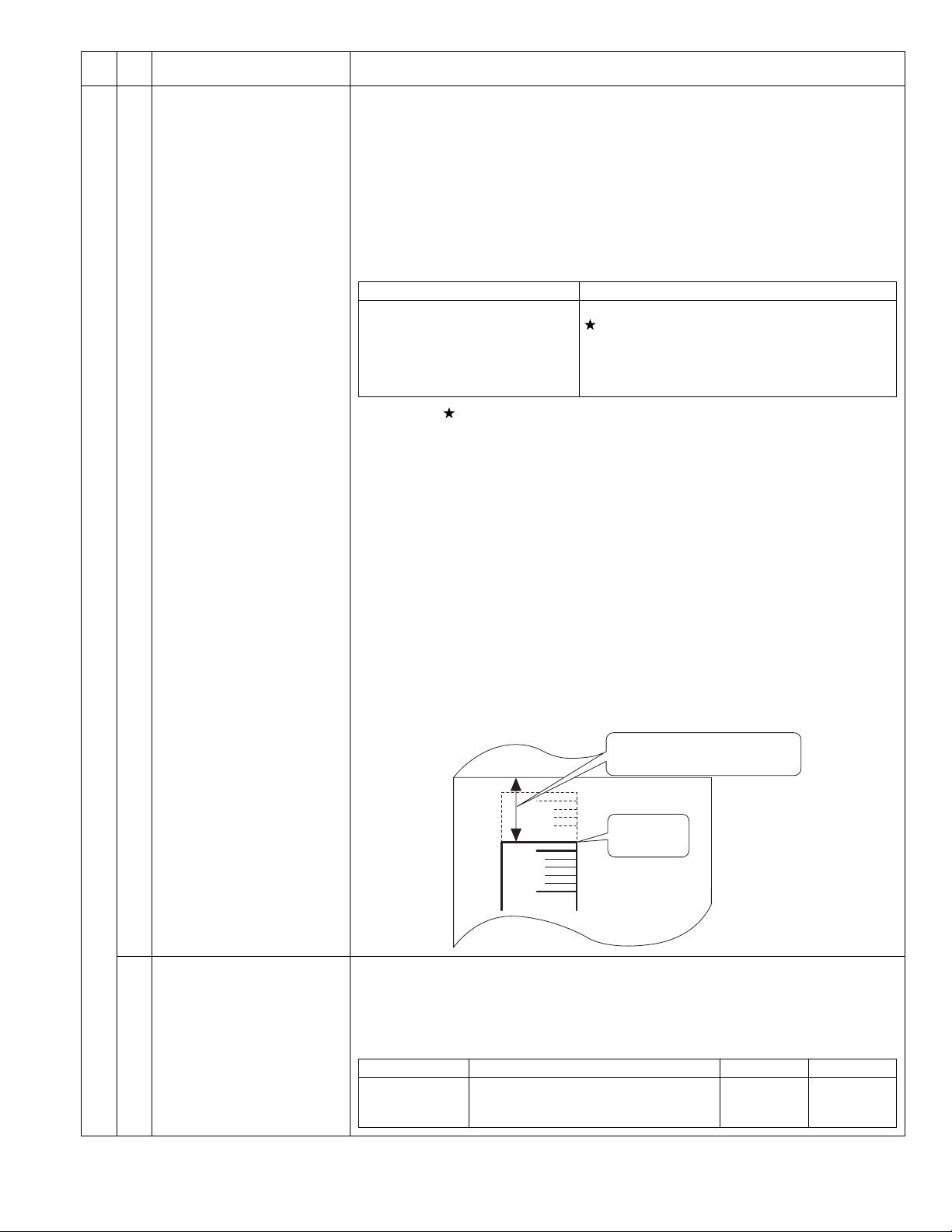
Main
code
Sub
code
Contents Details of operation
50 01 Image lead edge adjustment Used to adjust the copy image position and the lead edge void amount on the copy paper. This
adjustment is made by adjusting the image scan start position at 100% and the print start position
(resist roller ON timing).
(Operating procedure)
When this simulation is executed, the current set value is displayed in two digits. (Center value: 50)
When the [AUTO/TEXT/PHOTO] key is pressed, the setting mode and the display are switched.
Enter the adjustment value with the Numeric keys and press the [START] key, and the entered value
is set and a copy is made. (Adjustment range 1 ~ 99) When the [Interrupt] key is pressed, the
entered value is saved and the machine goes into the sub code entry standby mode. When the [CA]
key is pressed, the entered value is saved and the simulation is terminated. When the adjustment is
made with 1st tray paper feed, all the adjustment values at the paper feed ports become the same.
(When the adjustment value is increased by 1, the position is shifted by about 0.1mm.)
LED Adjustment mode
AUTO, 1st tray indicator
AUTO, 2nd tray indicator
AUTO, Bypass tray indicator
TEXT indicator
PHOTO indicator
AUTO, TEXT, PHOTO indicator
Print start position (1st tray paper feed)
Print start position (2nd / 3rd / 4th tray paper feed)
Print start position (Bypass tray)
Image lead edge void amount
Image scan start position
Image rear edge void amount
* The mark, " ", indicates that it is supported only for the installed model, and it is skipped for
non-installed models.
Note:When printing is made with bypass tray, use A3 paper.
When the adjustment value of the print start position is increased by 1, the resist roller ON
timing is delayed and the print image is reduced by 0.1mm. When the adjustment value of the
image scan start position is increased by 1, the scan start position is shifted to the home
position by 0.1mm.
[Adjustment procedure]
(1) Set the print start position (A) (AUTO exposure ON), the lead edge void amount (B) (TEXT ON),
and the scan start position (C) (PHOTO ON) to <1>, and make a 100% copy.
(2) Measure the image loss (R mm) of the scale. Set as C=10 x R (mm). (Example: Set to 40.)
When the value of C is increased by 10, the image loss is decreased by 1mm. (Default: 50)
(3) Measure the distance between the paper lead edge and the image print start position.
Set as A=10 x H (mm). (Example: Set to 50.)
When the value of A is increased by 10, the image lead edge is shifted toward the paper lead
edge by 1mm. (Default: 50)
(4) Set the lead edge void area as B=50 (2.5mm). (Default: 50)
When the value of B is increased by 10, the void is increased by about 1mm.
(For 25 or less, however, the void amount is zero.)
(Example)
06 Copy lead edge position
adjustment (SPF/RSPF)
(Only when the SPF/RSPF is
installed)
Distance from the paper lead edge
to the image lead edge H = 5mm
Image loss
5mm
10mm
R=4mm
Used to make the SPF copy lead edge position adjustment.
* When the adjustment value of the document scan start position is increased by 1, the scan start
timing is advanced by 0.1mm. The print image is shifted to the reverse side of the scan start
position.
(Adjustment range: 1 ~ 99, Default: 50)
<Adjustment items>
LED Item Default Variable range
AUTO indicator
TEXT indicator
PHOTO indicator
Front document scan position adjustment
Back document scan position adjustment
Rear edge void adjustment (SPF)
50
50
50
1 ~ 99
1 ~ 99
1 ~ 99
AR-5520 SIMULATIONS 7-20
Page 48

Main
code
Sub
code
Contents Details of operation
50 10 Paper off-center adjustment Used to adjust the positions of copy images on copy paper and the center offset position when
scanning the document.
(Operating procedure)
When this simulation is executed, the current set value is displayed. Enter the adjustment value with
the Numeric keys and press the [START] key, and the entered value is stored and a copy is made.
When the [Interrupt] key is pressed, the entered value is saved and the machine goes into the sub
code entry standby mode. When the [CA] key is pressed, the entered value is saved and the
simulation is terminated.
(When the set value is increased by 1, the position is shifted by 0.1mm.)
(Adjustment range: 1 ~ 99, Default: 50)
<Supplement>
When the adjustment value is increased, the image is shifted to the left. When the adjustment value
is decreased, the image is shifted to the right.
LED Adjustment mode
AUTO, 1st tray indicator
AUTO, 2nd tray indicator
AUTO, 3rd tray indicator
AUTO, 4th tray indicator
AUTO, Bypass tray indicator
TEXT, 1st tray indicator
Print center offset (1st tray paper feed)
Print center offset (2nd tray paper feed)
Print center offset (3rd tray paper feed)
Print center offset (4th tray paper feed)
Print center offset (Bypass tray)
2nd print center offset (1st tray paper feed)
When this mode is selected, the S-D mode is automatically set.
Supported for the installed models only. Skipped for the models without installation.
Note: When the adjustment value is too great, the outside area of shading may be scanned, resulting
in black streaks on copy paper.
When printing is made with bypass tray, use A3 paper.
When a document is scanned in the OC mode in the back surface center off-set adjustment
and printing is made in the S-D mode, the first document is scanned and then the second
document is scanned automatically.
12 Document off-center adjustment Used to make the document scan off-center adjustment.
(Adjustment range: 1 ~ 99, Default: 50)
* When the adjustment value is increased by 1, the print image is shifted by 0.1mm to the left
when the scan start position is put on the upper side.
<Adjustment item>
LED Item Default Variable range
AUTO indicator
TEXT indicator
Platen document scan
SPF document front scan
50
50
1 ~ 99
1 ~ 99
(Only when the SPF/RSPF is installed)
PHOTO indicator
RSPF document back scan
50
1 ~ 99
(Only when the RSPF is installed)
AR-5520 SIMULATIONS 7-21
Page 49

Main
code
Sub
code
Contents Details of operation
50 18 Duplex copy memory reverse
position adjustment
(Only when the SPF/RSPF is
installed or in the duplex mode)
Used to adjust the memory reverse position in duplex copy. When this simulation is executed, the
current correction value is displayed.
Enter a correction value with the Numeric keys and press the [START] key, and the entered value
will be saved. (Adjustment range: 1 ~ 99, Default: 50)
LED Item
AUTO indicator
TEXT indicator
OC memory reverse output position
SPF memory reverse output position
Printing of the front surface in the S-D mode and printing of the even pages in the D-S mode are
performed as reverse memory copying from the rear edge of the document.
When, therefore, the printing position adjustment of output image is required, perform the adjustment
as follows:
The image direction in reverse memory copying is shown in the figure below. That is, when the
document scan direction is as shown with the arrow, the output image is printed from the rear edge
of scanning. If, therefore, the print edge section is shifted, set the reference chart with the reference
position at the rear edge and use this simulation to change the set value in order to adjust the print
lead edge position.
Since printing is started at the print start position and performed from the last, saved data in the
memory to the head data, the lead edge position of an image is adjusted by changing the last data
position saved in the memory.
Document
transport
direction
Scanning lead edge
Paper
transport
direction
Print lead edge
Lead edge void (1)
Print start position
19 Duplex copy rear edge void
adjustment
(Duplex model only)
Scanning end position
(Scanning cut by void
Scanning
direction
Scanning
rear edge
(1) as default)
Rear edge void
Print rear edge
Note:A document is scanned in the OC mode. When printing is made in the S-D mode, the first
document is scanned and then the second document is automatically scanned.
Used to adjust the rear edge void amount in duplex copy.
(Operating procedure)
When this simulation is executed, the current set value is displayed in two digits.
(Adjustment range: 1 ~ 99, Center value: 50)
* When the set value is increased by 1, the void amount is increased by about 0.1mm.
Press the [AUTO/TEXT/PHOTO] key to select a suitable setting mode and a display. Enter the
adjustment value with the Numeric keys and press the [START] key, and the entered value is saved
and a copy is made. (Paper information is cleared after every copying).
When the [Interrupt] key is pressed, the entered value is saved and the machine goes into the sub
code entry standby mode. When the [CA] key is pressed, the entered value is saved and the
simulation is terminated.
LED Item
AUTO indicator
TEXT indicator
PHOTO indicator
Paper rear edge void amount (First print surface)
Paper rear edge void amount (Second print surface)
Print start position (duplex back surface)
AR-5520 SIMULATIONS 7-22
Page 50

Main
Sub
code
code
51 02 Resist amount adjustment Used to adjust the contact pressure of the machine resist roller and the RSPF resist roller onto the
53 08 SPF scanning position automatic
adjustment
(Only when the SPF/RSPF is
installed)
Contents Details of operation
paper.
(Operating procedure)
When this simulation is executed, the current set value is displayed.
When the [AUTO/TEXT/PHOTO] key is pressed, the following set items are changed sequentially.
Enter an adjustment value with the Numeric keys and press the [START] key, and the entered value
will be saved and a copy will be made. (Adjustment range: 1 ~ 99, Default: 50)
When the [CA] key is pressed, the entered value is saved and the simulation is terminated.
LED Adjustment mode
AUTO, 1st tray indicator
AUTO, 2nd tray indicator
AUTO, 3rd tray indicator
AUTO, 4th tray indicator
AUTO, Bypass tray indicator
AUTO, TEXT, PHOTO indicator
AUTO, TEXT indicator
AUTO, PHOTO indicator
TEXT, PHOTO indicator
TEXT indicator
Supported for the installed models only. Skipped for the models without installation.
Place the white chart so that it covers both the SPF scan glass and the OC glass. Close the OC
cover. When this simulation is executed, the current adjustment value is displayed as the initial
display. When the [START] key is pressed, the mirror unit scans from the home position to the SPF
scan position with the current adjustment value displayed, and the SPF glass cover edge is
calculated from the difference between the SPF glass cover edge and the OC side document glass
CCD output level.
* The default is 50, the adjustment range is 1 ~ 99, and the adjustment unit 1= about 0.127mm.
If the adjustment is completed normally, the adjusted value is displayed. If not, the Misfeed indicator
lights up with the current set value displayed. When the [START] key is pressed again with the
Misfeed indicator ON, the execution is repeated again. When the [Interrupt] key or the [CA] key is
pressed during execution, "- -" is displayed and the operation is canceled. The mirror returns to its
home position and the simulation mode is terminated. In the case when the [Interrupt] key is
pressed, the machine goes into the sub code input standby mode. In the case when the [CA] key is
pressed, all the lamps are turned off.
LED Display mode
AUTO indicator
TEXT indicator
1st tray paper feed
2nd tray paper feed
3rd tray paper feed
4th tray paper feed
Bypass tray
RSPF document feed (Front surface)
RSPF document feed (Back surface)
RSPF document (A5) paper feed (Back surface)
Duplex back surface
PS solenoid prior pulling time adjustment in manual
paper feed
SPF scan position automatic adjustment
SPF scan position manual adjustment
10 SPF document scan position
select setting
60 01 SDRAM (image memory area)
access check
Setting is changed depending on whether the SPF unit and the SPF document glass holding section
are glass dirt prevention parts or not.
For the combination of this machine and the AR-RP10/AR-SP10, the set value is set to [1].
If the set value is changed to [0], black streaks may be produced on a copy paper due to dirt on the
SPF glass.
When this simulation is executed, the current code number is displayed.
Enter a code number corresponding to the SPF unit to be used and press [START] key to save the
setting.
Code number Mode
0
1
Though this setting is changed, the other adjustment values are not affected. (The set value remain
unchanged.)
When replacing or installing the SPF unit, perform this simulation to set the position and then
execute the scan position automatic adjustment.
Access check to the SDRAM is made.
When this simulation is executed, the SDRAM check is started. Fusing execution. the start LED turns
OFF. If an error occurs, the following LED turns ON. When the operation is normally completed, the
START indicator is turned ON.
After completion of checking, press [CA] key to reboot the machine.
LED Display mode
Misfeed indicators
Paper required indicator
Set to the scan position equivalent to the old-type SPF unit (the previous
model of AR-SP6/RP6).
Set to the scan position for dirt prevention. *Default
Write end error
Read end error
AR-5520 SIMULATIONS 7-23
Page 51

Main
Sub
code
code
61 02 Laser power correction ON/OFF Used to set whether the laser power correction is performed or not halfway.
03 HSYNC output check When the [START] key is pressed, HSYNC is performed and the polygon motor is rotated for 30 sec.
63 01 Shading check The detection level of the white plate for shading is displayed.
07 SPF automatic correction
(Only when the SPF/RSPF is
installed)
64 01 Self print The optical system status is ignored and a self print is made. Also when a print command is sent
Contents Details of operation
When [START] key is pressed, the entered value is saved and the screen shifts to the sub code
input standby mode.
Code number Mode
0 Not correct
1 Correct *Default
Every time when HSYNC is detected, the ZOOM indicator is lighted for 100msec.
(Operating procedure)
When the [START] key is pressed in the sub code input standby mode, the mirror base unit moves to
the white plate for shading and the copy lamp is lighted. Until the light quantity of the copy lamp is
stabilized, the sub code of "01" is displayed on the 7-seg display. When the light quantity of the copy
lamp is stabilized, it is revised every second, and the level of one pixel at the CCD center where no
correction is made is detected for 10 sec, and the detected level is displayed in hexadecimal on the
7-seg display. After completion of 10 sec detection, the machine goes into the sub code input
standby mode.
The SPF white correction start pixel position is automatically adjusted.
This is performed after replacement of the lens. Open the SPF unit and press the [START] key, and
the position (which pixel) of the white sheet for SPF exposure correction in the SPF position is
displayed on the 7-seg display.
If the value is 93 ~ 229, it is displayed on the 7-seg display and is written into the EEPROM.
If the value is 0 ~ 92 or 230 ~ 999, it is displayed on the 7-seg display but is not written into the
EEPROM.
If the value is 1000 or above, "-------" is displayed on the 7-seg display and is not written into the
EEPROM.
The pixel position -34 written into the EEPROM is considered as the SPF white correction start pixel
of the machine.
When shi simulation is executed with the SPF unit closed, an error will occur.
from the host, printing is performed.
(Operating procedure)
When this simulation is executed, warm-up is performed and the START indicator is lighted.
(However, the scanner is invalid and no initial operation is made.)
Enter the code number with the Numeric keys, and select a tray with the PAPER SELECT key and
press the [START] key. The selected tray start paper feed and printing is performed in the selected
pattern.
* Only the tray lamp and the online lamp are lighted, and no other lamps are lighted.
Code
number
0 Grid pattern <1>1/236
1 Dot pattern <1>1/1
2 Regular pitch pattern
MbyN (Sub scan)
3 Regular pitch pattern
MbyN (Main scan)
4 Black background belt
(A4/A4R)(Paper F-R end)
5 Black background belt (All surface) No pattern AUTO indicator
6 White background belt (All surface) No pattern AUTO indicator
7 ht(All surface) No pattern AUTO indicator
8 Black square No pattern AUTO indicator
9 Lead edge black No pattern AUTO indicator
10 Form of No pattern AUTO indicator
* When the destination is of AB series, print data are made in A3 size.
(Therefore, A3 paper is desirable.)
* When the destination is of inch series, print data are made in WLT size.
(Therefore, WLT paper is desirable.)
Print pattern Image output Lighted LED
<2>1/128
<3>1/255
<4>2/254
<2>2/2
<3>1/255
<1>1/1
<2>1/2
<3>2/2
<1>1/1
<2>1/2
<3>2/2
<1>1%
<2>6%
<3>35%
AUTO indicator
TEXT indicator
PHOTO indicator
AUTO indicator & TEXT
indicator
AUTO indicator
TEXT indicator
PHOTO indicator
AUTO indicator
TEXT indicator
PHOTO indicator
AUTO indicator
TEXT indicator
PHOTO indicator
AUTO indicator
AUTO indicator
AUTO indicator
AR-5520 SIMULATIONS 7-24
Page 52

[8] USER PROGRAMS
The user programs allow the parameters of certain functions to be set, changed, or canceled as desired.
1. List of user programs
This copier has the following user programs.
1
Program
3
No
Description Default Parameters
"Auto clear time" automatically returns the copy settings to the initial
settings when a certain period of time elapses after a copy is made.
This program is used to select the period of time. "Auto clear time"
1
can also be disabled. 60sec
This function automatically switches the machine to a low power
consumption state if the set duration of time elapses without the
machine being used when the power is on.
The POWER SAVE indicator lights up, however, the keys on the
2
operation panel can be used. Normal operation automatically
resumes when a key on the operation panel is pressed, an original
is placed, a print job is received, or scanning is begun from a
computer.
This function automatically switches the machine to a state that
consumes even less power than preheat mode if the set duration of
time elapses without the machine being used when the power is on.
All lights except the POWER SAVE indicator and ON LINE indicator
3
go off. To resume normal operation, press the [START] key ( ).
Normal operation also resumes automatically when a print job is
received or scanning is begun from a computer. While in auto power
shut-off mode, no keys (except the [START] key ( )) can be used.
When copying using the SPF/RSPF, during the period of time that
the SPF/RSPF indicator blinks after an original has been scanned
4
(about 5 seconds), a subsequent original can be placed and
automatically fed into the machine.
Use this setting to enable or disable auto power shut-off.
5
When copying multiple originals onto a single sheet of paper (2 IN 1
/ 4 IN 1 copy), this function can be used to print a solid or broken
6
borderline around each original image.
When the auto paper select function is enabled and there is no
paper that is the same size as the original and loaded in the same
orientation, this function will automatically select paper of the same
size that is loaded in the opposite orientation, and rotate the image
7
90 degrees so that it is copied on the paper in the correct
orientation.
When the auto ratio select function is operating and the original and
paper are loaded in opposite orientations, this function rotates the
image so that it is copied on the paper in the correct orientation.
This function automatically selects paper that is the same size as
the original placed in the SPF/RSPF, or the same size as that
8
selected with the [ORIGINAL] key (only for sizes 5-1/2" x 8-1/2", 8-1/
2" x 11", 8-1/2" x 11"R, 8-1/2" x 14" and 11" x 14"). The function can
be disabled.
If the paper runs out during printing and there is paper of the same
size and orientation in another tray, this function automatically
9
switches to that tray (excluding the bypass tray). The function can be
disabled.
Use to enable or disable "Auditing mode".
10
"Auditing mode" is initially disabled.
Use to set up account numbers. Up to 20 accounts can be
11
established.
1min
5min
OFF
ON
OFF
ON
ON
ON
OFF
-
1 (OFF)
2 (10sec)
3 (20sec)
4 (60sec)
5 (90sec)
6 (120sec)
1 (1min)
2 (5min)
3 (30min)
4 (60min)
5 (120min)
6 (240min)
1 (5min)
2 (30min)
3 (60min)
4 (120min)
5 (240min)
0 (OFF)
1 (ON)
0 (OFF)
1 (ON)
1 (OFF)
2 (Solid line)
3 (Broken line)
0 (OFF)
1 (ON)
0 (OFF)
1 (ON)
0 (OFF)
1 (ON)
0(OFF)
1(ON)
None
Program name
Auto clear time
Preheat mode
Auto power shut-off timer
Stream feeding mode*
Auto power shut-off
setting
Border line for
2 IN 1 / 4 IN 1*
Rotation copy*
2
2
Auto paper select mode*
Auto tray switching*
3
Auditing mode
Account number entry
Account number change 12 Use to change an account number. - None
*1 On models with a SPF/RSPF.
*2 Setting cannot be made for the AR-5516S/AR-5520S (models which are not provided with e-sort). Though set to ON, it is disabled.
*3 Valid only for the tray 1 of the AR-5516/AR-5520/AR-5516D/AR-5520D.
AR-5520 USER PROGRAMS 8-1
Page 53

Program name
Program
No
Account number deletion
13
Number of copies per
account 14
Resetting account
Erase width adjustment*
15
2
16
Layout in 2 IN 1 copy*
2
Description Default Parameters
Use to delete an account number.
A single account number can be deleted, or all account numbers at
once.
This displays the number of copies made by each account.
The maximum count is 49,999. If this number is exceeded, the count
will start over from 0.
Use to reset the copy count of an account to 0.
The copy count of a single account or of all accounts can be reset.
Use this setting to set the width of erasure of shadows that appear
around the edges and at the binding margin when a book or similar
original is copied.
Use this setting to select the layout pattern when two original pages
are copied onto a single sheet of paper.
2 IN 1 copy
Delete
single
account
-
Reset single
account
1/2" (10mm)
0(Delete single account)
1(Delete all accounts)
None
0(Reset single account)
1(Reset all accounts)
1 (0" (0mm))
2 (1/4" (5mm))
3 (1/2" (10mm))
4 (3/4" (15mm))
5 (1" (20mm))
1 (Pattern 1)
2 (Pattern 2)
Layout in 4 IN 1 copy*
17
Pattern 1
2
Use this setting to select the layout pattern when four original pages
Pattern 2
are copied onto a single sheet of paper.
4 IN 1 copy
Pattern 1
1 (Pattern 1)
2 (Pattern 2)
3 (Pattern 3)
4 (Pattern 4)
Image rotation in duplex
copying*
3
18
Pattern 1 Pattern 2 Pattern 3 Pattern 4
When a one-sided portrait original is placed in a horizontal
orientation (8-1/2" x 11" or 8-1/2" x 14" size) for two-sided copying,
20
the top and bottom of the images on the front and back of the paper
Pattern 1
OFF
0 (OFF)
1 (ON)
will be opposite to each other,
Location of the margin*
Margin width*
2
2,*4
Use this setting to switch between the margin at the top edge and
21
the margin at the left edge.
Use this setting to set the margin width.
Left edge
1 (Left edge)
2 (Top edge)
1 (0" (0mm))
2 (1/4" (5mm))
22
1/2" (10mm)
3 (1/2" (10mm))
4 (3/4" (15mm))
5 (1" (20mm))
Resolution in Auto/Text
mode 23
The copy resolution in auto and text mode is normally 300 dpi.
If high-quality copies are preferred, use this setting to change the
300dpi
1 (300dpi)
2 (600dpi)
resolution to 600 dpi.
Memory allocated to
printer mode*
2
Use this to change the proportion of IMC memory used for printer
mode.
24
50%
1 (30%)
2 (40%)
3 (50%)
4 (60%)
5 (70%)
Key auto repeat
Use this setting to select whether or not holding down a key causes
repeated input of the key. For keys that normally cause a set value
25
to increase when held down (for example, holding down the [ZOOM]
ON
0 (OFF)
1 (ON)
key ( , )), this program can be used to have the set value not
change when the key is held down.
*2 Setting cannot be made for the AR-5516S/AR-5520S (models which are not provided with e-sort). Though set to ON, it is disabled.
*3 When there are two or more paper trays.
*4 On models with automatic two-sided copying.
AR-5520 USER PROGRAMS 8-2
Page 54

Program name
Key press time
Program
No
26
Description Default Parameters
Use this setting to select how long a key must be pressed for the
input to be accepted. By selecting a longer time, you can prevent
settings from being changed by the accidental pressing of a key.
Minimum
(current
response
speed)
1 (Minimum
(current response speed))
2 (0.5sec)
3 (1.0sec)
4 (1.5sec)
5 (2.0sec)
Audible signals volume
Base setting beep signal
Number of copies limit
Use close paper size
This sets the volume of beep signals.
27
Use this to sound a beep when a base setting is selected.
28
Use this setting to select 99 or 999 for the maximum number of
29
copies.
When this function is enabled, printing in printer mode will
automatically continue using a different size of paper if the specified
30
size of paper runs out in all trays. This feature does not function in
Low
(current
volume)
OFF
999 copies
OFF
1 (Low (current volume))
2 (High)
3 (OFF)
0 (OFF)
1 (ON)
1 (99 copies)
2 (999 copies)
0 (OFF)
1 (ON)
copy mode.
Default tray setting
Use this program to select a default tray. This tray is automatically
selected each time the power is turned on or each time the machine
reverts to the initial settings.
31
Tray 1
1 (1st tray)
2 (2nd tray)
3 (3rd tray)
4 (4th tray)
5 (Bypass tray)
Default exposure mode
Use this program to set "AUTO", "TEXT", or "PHOTO" as the default
exposure mode.
32
AUTO
1 (AUTO)
2 (TEEXT)
3 (PHOTO)
USB2.0 mode switch 33 Used to switch USB2.0 mode between Full-Speed and High-Speed. High-Speed 1(Full-Speed)
2(High-Speed)
Sort auto select*
1
34 Use this setting to select the default output mode for copying from
the SPF/RSPF.
Sort 1(OFF)
2(Sort)
3(Group)
*1 On models with a SPF/RSPF.
AR-5520 USER PROGRAMS 8-3
Page 55

2. Setting the user programs
1) Hold down the [Light] key ( ) until the alarm indicators
( , , , , ) blink.
•The display shows "- -" with the left hyphen blinking.
2) Enter the program number with the numeric keys.
•The selected program number blinks.
•For example, to select "Auto clear timer", press the [1] key.
Note:If you enter the wrong number, press the [CLEAR] key ( ) and
then enter the correct number.
3) Press the [START] key ( ).
•The selected program number stops blinking and lights steadily.
•The currently selected setting code blinks on the right side of the
display.
3. Toner cartridge life
The toner level is indicated by a 6-level display. Use it as a guideline for
replacing the toner cartridge.
1) Hold down the [Light] key ( ) until the alarm indicators ( , ,
, , ) blink.
•The display will show "- -".
2) Hold down the [Copy ratio display] key ( ) for more than 5
seconds.
•The approximate quantity of toner remaining will be indicated in the
display as a percentage. ("100", "75", "50", "25", "10" is displayed.)
When the percentage is less than 10%, "LO" will be displayed.
3) Press the [Light] key ( ) to return to the normal display.
•The alarm indicators ( , , , , ) go off. The display
returns to the number of copies display.
4) Enter the desired setting code by pressing a numeric key.
•The selected setting code blinks.
•For example, to select 90 seconds, press the [5] key.
Note:If you enter the wrong number, press the [CLEAR] key ( ) and
return to step 2).
5) Press the [START] key ( ).
•The selected setting code stops blinking and lights steadily.
Note:To select a setting for another system setting, press the [CLEAR]
key ( ) and then return to step 2.
6) Press the [Light] key ( ) to complete the settings.
•The alarm indicators ( , , , , ) go off and the display
returns to the number of copies display.
AR-5520 USER PROGRAMS 8-4
Page 56

[9]TROUBLE CODE LIST
1.Trouble code list
Main code Sub
code
E7 01 Duplex model memory error/ Image data error
02 LSU trouble
06 Image data decode error
10 Shading trouble (Black correction)
11 Shading trouble (White correction)
16 Abnormal laser output
F2 02 Toner supply abnormality
04 Improper cartridge (destination error, life cycle
error)
Identification error
Model error
Type error
Destination error
Data abnormality
Misc error
40 ATC sensor abnormality
F5 02 Copy lamp lighting abnormality
H2 00 Thermistor open
H3 00 Heat roller high temperature detection
H4 00 Heat roller low temperature detection
H5 01 5 continuous POUT not-reached error
L1 00 Scanner feed trouble
L3 00 Scanner return trouble
L4 01 Main motor lock detection
31 Fusing FAN lock detection
32 PSFAN lock detection
L6 10 Polygon motor lock detection
U2 04 EEPROM read/write error (serial communication
error)
11 Counter check sum error (EEPROM)
12 Adjustment value check sum error (EEPROM)
40 CRUM chip communication error
-- Auditor NOT READY
CH ON None Side door open
CH Blink None Developing cartridge not installed
Content
2.Details of trouble codes
Main
Sub
code
code
E7 01 Content Duplex model memory error/ Image data error
Detail 1. The memory capacity for the duplex model
Cause 1. The memory capacity on the MCU PWB is
Check
and
remedy
02 Content LSU trouble
Detail The BD signal from the LSU cannot be
Cause LSU connector or LSU harness defect or
Check
and
remedy
06 Content Image data decode error
Detail Image expansion error
Cause MCU PWB abnormality
Check
and
remedy
10 Content Shading trouble (Black correction)
Detail The CCD black scan level is abnormal when
Cause Improper connection of the CCD unit flat cable
Check
and
remedy
11 Content Shading trouble (White correction)
Detail The CCD white scan level is abnormal when
Cause Improper connection of the CCD unit flat cable
Check
and
remedy
machine is wrong. Insufficient memory
capacity.
2. Duplex setting is set for a single surface
model.
wrong.
2. Setting for a single surface model is wrong.
1. Use SIM26-39 to check to confirm that the
memory capacity is 64MB. If it is not 64MB,
replace the MCU PWB.
2. If SIM26-04 is set to 1, change the setting to
0. If it is 0, replace the MCU PWB.
detected in a certain cycle. (Always OFF or
always ON)
disconnection
Polygon motor rotation abnormality
Laser beams are not generated.
MCU PWB abnormality.
Check connection of the LSU connector.
Execute SIM 61-03 to check the LSU
operations.
Check that the polygon motor rotates normally.
Check that the laser emitting diode generates
laser beams.
Replace the LSU unit.
Replace the MCU PWB.
USB cable trouble
Replace the MCU PWB.
Replace the USB cable.
the shading.
CCD unit abnormality
MCU PWB abnormality.
Check connection of the CCD unit flat cable.
Check the CCD unit.
the shading.
Dirt on the mirror, the lens, and the reference
white plate
Copy lamp lighting abnormality
CCD unit abnormality
MCU PWB abnormality
(When occurred in the SPF scan position.)
Improper installation of the mirror unit
Clean the mirror, the lens, and the reference
white plate.
Check lighting and the light quantity of the copy
lamp (SIM05-03).
Check the CCD unit.
Check the MCU PWB.
Details of trouble
AR-5520 TROUBLE CODE LIST 9-1
Page 57

Main
Sub
code
code
E7 16 Content Abnormal laser output
Detail When the laser output is stopped, HSYNC is
Cause Laser abnormality
Check
and
remedy
F2 02 Content Toner supply abnormality
Detail When toner near end is detected with the toner
Cause ATC sensor abnormality
Check
and
remedy
04 Content •Improper cartridge (Destination error, life cycle
Detail •The destination of the machine differs from
Cause CRUM chip defect
Check
and
remedy
40 Content ATC sensor abnormality
Detail ATC sensor value abnormality
Cause Connector connection trouble
Check
and
remedy
detected.
MCU PWB abnormality.
Replace the LSU.
Replace the MCU PWB.
supply time of 50% or less.
When the toner supply time exceeds 300%.
Improper supply
Replace the toner cartridge.
Replace the developing unit.
error)
•Identific t ion error
•Model error
•Type error
•Destination error
•Data abnormality
•Misc error
that of the CRUM.
•The trade mark code of the CRUM differs.
•The company code of the CRUM differs.
•The boot program model code does not
coincide with the CRUM model code.
•When the CRUM type is other than genuine/
conversion/production rotation.
•The machine destination differs from the
CRUM destination.
•When an error value is included in the initial
check information.
•When the max. toner supply time is 00.
•When the print hard stop is 00.
•When the Misc information is other than "Not
used (FFh)."
Improper developing unit
Replace the toner dartridge.
Replace the developing unit.
Toner cartridge installation trouble
Sensor breakdown
Connect the connector again.
Install the toner cartridge again.
Replace the toner cartridge with a normal one.
Details of trouble
Main
Sub
code
code
F5 02 Content Copy lamp lighting abnormality
Detail The copy lamp does not turn on.
Cause Copy lamp abnormality
Check
and
remedy
H2 00 Content Thermistor open
Detail The thermistor is open.
Cause Thermistor abnormality
Check
and
remedy
H3 00 Content Heat roller high temperature detection
Detail The fusing temperature exceeds 240C°.
Cause Thermistor abnormality
Check
and
remedy
Copy lamp harness abnormality
CCD PWB harness abnormality.
Use SIM 5-3 to check the copy lamp
operations.
When the copy lamp lights up.
Check the harness and the connector between
the CCD unit and the MCU PWB.
When the copy lamp does not light up.
Check the harness and the connector between
the copy lamp unit and the MCU PWB.
Replace the copy lamp unit.
Replace the MCU PWB. "
The fusing unit is not installed.
Control PWB abnormality
Fusing section connector disconnection
The fusing unit is not installed.
Check the harness and the connector between
the thermistor and the PWB.
Use SIM 14 to clear the self diagnostic display.
Control PWB abnormality
Fusing section connector disconnection.
Use SIM 5-02 to check the heater lamp
blinking operation.
When the lamp blinks normally.
Check the thermistor and its harness.
Check the thermistor input circuit on the control
PWB.
When the lamp keeps ON.
Check the power PWB and the lamp control
circuit on the MCU PWB.
Use SIM 14 to clear the self diagnostic display.
Details of trouble
AR-5520 TROUBLE CODE LIST 9-2
Page 58
Main
Sub
code
code
H4 00 Content Heat roller low temperature detection
Detail When the fusing temperature is 150C° or less
Cause Thermistor abnormality
Check
and
remedy
H5 01 Content 5 continuous POUT not-reached error
Detail When 5 continuous not-reached jams to the
Cause Jam paper is not removed from the fusing unit.
Check
and
remedy
L1 00 Content Scanner feed trouble
Detail Though the specified steps of motor pulses are
Cause Mirror unit abnormality
Check
and
remedy
in 55 sec from starting warming-up.
When the warm-up complete temperature is
not reached in 30 sec from reaching 150C°.
When the fusing temperature is less than
100C° in 20 sec from the ready state.
When the fusing temperature is less than
145C° for more than 300ms in the ready state
or in printing.
When the fusing temperature is less than
100C° for more than 300ms in the standby
mode at a low temperature.
Heater lamp abnormality
Thermostat abnormality
Control PWB abnormality
Use SIM 5-02 to check the heater lamp
blinking operation.
When the lamp blinks normally.
Check the thermistor and its harness.
Check the thermistor input circuit on the control
PWB.
When the lamp does not light up.
Check for disconnection of the heater lamp and
the thermostat. Check the interlock switch.
Check the power PWB and the lamp control
circuit on the MCU PWB.
Use SIM 14 to clear the self diagnostic display.
paper exit sensor (POUT) occur.
The jam counter is backed up and it is used in
a job after turning on the power.
(Jam paper remains.)
Paper exit sensor breakdown or harness
connection trouble
Fusing unit installation trouble
Check for jam paper remaining in the fusing
unit. (winding, etc.)
Check the POUT sensor harness, and check
installation of the fusing unit.
Use SIM14 to clear the self diag display.
outputted, the mirror home position sensor
remains ON.
The scanner wire is disconnected.
The origin detection sensor abnormality
Mirror motor harness abnormality
Use SIM 1-1 to check the mirror reciprocating
operations.
When the mirror does not feed.
Check for disconnection of the scanner wire.
Check the harness and the connector between
the mirror motor and the MCU PWB.
Replace the mirror unit.
Replace the MCU PWB.
When the mirror does feed.
Use SIM 1-2 to check the mirror home position
sensor.
Details of trouble
Main
Sub
code
code
L3 00 Content Scanner return trouble
Detail Though the specified steps of motor pulses are
Cause Mirror unit abnormality
Check
and
remedy
L4 01 Content Main motor lock detection
Detail The main motor does not rotate.
Cause Main motor unit abnormality
Check
and
remedy
31 Content Fusing fan lock detection
Detail The fusing fan does not rotate.
Cause Fan trouble or harness contact trouble and
Check
and
remedy
32 Content PSFAN lock detection
Detail The PSFAN does not rotate.
Cause Fan trouble or harness contact trouble and
Check
and
remedy
outputted, the mirror home position sensor
does not turn ON.
Scanner wire disconnection
Origin detection sensor abnormality
Mirror motor harness abnormality
Use SIM 1-1 to check the mirror reciprocating
operations.
When the mirror does not return.
Check for disconnection of the scanner wire.
Check the harness and the connector between
the mirror motor and the MCU PWB.
Replace the mirror unit.
Replace the MCU PWB.
When the mirror does feed.
Use SIM 1-2 to check the mirror home position
sensor.
After rotation of the main motor, the motor lock
signal is detected for 1 sec or more.
During rotation of the main motor, the motor
lock signal is detected for 1 sec.
When the main motor is stopped, the motor
lock signal is not detected for 5sec or more.
(Though the motor is stationary, it is judged as
stable rotation.)
Improper connection or disconnection the main
motor and the harness.
MCU PWB abnormality
Use SIM 25-01 to check the main motor
operations.
Check connection of the main motor harness/
connector.
Replace the main motor.
Replace the MCU PWB.
Sampling is performed in 50msec interval, and
the normal signal cannot be detected 5 times
continuously in 1 sec.
disconnection
Use SIM05-02 to check the operations of the
fusing fan motor.
Heck connection of the fan harness and the
connector.
Replace the fan.
Replace the MCU PWB.
Sampling is performed in 50msec interval, and
the normal signal cannot be detected 5 times
continuously in 1 sec.
disconnection
Check connection of the fan harness and the
connector.
Replace the fan.
Replace the MCU PWB.
Details of trouble
AR-5520 TROUBLE CODE LIST 9-3
Page 59

Main
Sub
code
code
L6 10 Content Polygon motor lock detection
Detail The polygon motor does not rotate
Cause Polygon motor unit abnormality
Check
and
remedy
U2 04 Content EEPROM read/write error (Serial
Detail EEPROM access process error
Cause EEPROM abnormality
Check
and
remedy
11 Content Counter check sum error (EEPROM)
Detail Check sum error of the counter area in the
Cause EEPROM abnormality
Check
and
remedy
12 Content Adjustment value check sum error (EEPROM)
Detail Check sum error of the adjustment value area
Cause EEPROM abnormality
Check
and
remedy
40 Content CRUM chip communication error
Detail An error occurs during communication
Cause CRUM chip abnormality
Check
and
remedy
-- Content Auditor NOT READY
Detail
Cause
Check
and
remedy
None
CH
ON
Content Side door open
Detail The side door is open.
Cause Side door sensor abnormality
Check
and
remedy
After shifting the polygon motor, the motor lock
signal is detected for 20sec or more.
During rotation of the polygon motor, the motor
lock signal is detected for 1sec.
Improper connection or disconnection of the
polygon motor and the harness.
MCU PWB abnormality
Use SIM 61-3 to check the polygon motor
operations.
Check connection of the polygon motor
harness/connector.
Replace the polygon motor..
Replace the MCU PWB.
communication error)
Check that the EEPROM is properly set.
Use SIM 16 to cancel the trouble.
Replace the MCU PWB.
EEPROM
Check that the EEPROM is properly set.
Use SIM 16 to cancel the trouble.
Replace the MCU PWB.
in the EEPROM
Check that the EEPROM is properly set.
Use SIM 16 to cancel the trouble.
Replace the MCU PWB.
between the MCU and the CRUM chip.
The CRUM identification error occurs.
Developing unit disconnection
MCU PWB abnormality
Replace the toner cartridge.
Check installation of the developing unit.
Use SIM16 to cancel.
Replace the MCU PWB.
MCU PWB abnormality
Check that all the side doors are closed.
Replace the MCU PWB.
Details of trouble
Main
code
CH
Blink
Sub
code
None
Content Developing cartridge not installed
Detail The developing cartridge is not installed.
Cause Developing unit disconnection
Check
and
remedy
Communication with the CRUM cannot be
made in initial check of the CRUM.
MCU PWB abnormality
CRUM chip abnormality
Check installation of the developing unit.
Replace the MCU PWB.
Details of trouble
AR-5520 TROUBLE CODE LIST 9-4
Page 60

[10] MAINTENANCE
1. Maintenance table
X:Check(Clean, adjust, or replace when required.) O:Clean :Replace :Adjust :Lubricate
Unit name Part name
Drum
peripheral
Developing
section
Optical section Lamp unit Reflector O O O O
LSU Dust-proof glass O O O O
Paper feed
section
Paper transport
section
Fusing section Upper heat roller X O O
Drive section Gears - X X X
Paper exit
section
*1:Recommendable replacement time:50K(A4/Letter,6%print)
OPC drum Cleaning blade Side seal F/R X X X X
MC unit X
(MC charging electrode) - () () ()
(MC grid) - () () ()
(MC case) - () () ()
Transfer wire O O O O
Transfer paper guide O O O O
MC guide sheet (Cleaning blade attached) Drum fixing plate B X
Separation pawl
Star ring N2
Star ring φ 5
Pawl holder
Process frame unit X X X
Discharge holder O O O O
Developer X
DV seal X X X
Toner temperature sensor X X X X Check the sensor head surface.
DV side sheet X X X X
Mirror - O O O
No.2/3 mirror
unit
CCD peripheral Lens - O O O
Glass Table glass O O O O
Other Drive wire - X X X
Multi paper feed
section
PS roller O O O O
Transport (paper exit) rollers O O O O
Spring clutch O O O O
Pressure roller X O O O
Pressure roller bearing - X X O
Upper separation pawl X X X O
Lower separation pawl X X X O
Cleaning pad X X X
Belts - X X O
VOC filter
Mirror - O O O
Pulley - X X X
White Plate O O O O
Rail - X X X
Document cover O O O O
Take-up roller(manual / SPF) O O O O
Paper feed roller O O O
Spring clutch - O O O
When
calling
X
-
50K 100K 150K Remark
*1
AR-5520 MAINTENANCE 10-1
Page 61

2. Maintenance display system
Toner Life, 16K
Remaining
quantity
check *1
Remaining
quantity
LED ON Flash
Machine Operation allowed Stop
Developer Life 50K
LED ON at 50K of the
Machine Selection is available between Not Stop
Maintenance LED Selection is available among 50K, 25K,
Machine Not stop
*1: Installation of a new toner cartridge allows to display the remaining
quantity.
a. Press and hold the [Light] keys ([Light
and Dark] keys) for more than 5 sec, and
the machine will enter the user program
mode.
b. Press and hold the [%] key for more
than 5 sec, and the remaining quantity
will be displayed on the copy quantity
display in one of the following levels:
(Remaining quantity display levels:
100%, 75%, 50%, 25%, 10%, LO)
c. Press the [Light] keys ([Light and Dark]
keys) to cancel.
NEAR EMPTY
EMPTY
About 10%
developer count
and Stop by Service Simulation (SIM 26-
37) Setup.
(If Stop is selected, the LED will flash and
stop at 50K.)
* Default: Not Stop
* Clear: SIM 42-1
10K, 7.5K, 5K, and free (no lighting) with
SIM 21-1.
* Default: 50K
* Clear: SIM 20-1
C. DV seal attachment procedure
(When viewed from the front) (When view
Clearance with the
molt edge.
Must not be covered
0
Molt edge
reference
0.3
Side molt F Side molt R
.
DV Side
sheet F
0
0.5
0
0.5
Edge
reference
DVTH
molt
Attach with the
projection (rib)
reference
DV Side
sheet R
DVTH
Attach with the
line (mark-off line)
reference.
ed from the front)
Clearance with the
molt edge.
Must not be covered
0
molt
0.5
0
Molt edge
reference
0.3
.
3. Note for replacement of consumable parts
A. Toner cartridge
When a waste toner cartridge is removed from the machine, it must be
put in a polyethylene bag to avoid scattering of toner.
B. DV cartridge
Do not shake or put up the developer cartridge. Otherwise developer
may scatter.
AR-5520 MAINTENANCE 10-2
Page 62

[11]DISASSEMBLY AND ASSEMBLY
WARNING Before performing the disassembly procedure, be sure to
remove the power cord to prevent against an electric shock.
No. Item
1 High voltage section/Duplex transport section
2 Optical section
3 Fusing section
4 Paper exit section
5MCU
6 Optical frame unit
7LSU
8 Tray paper feed section/Paper transport section
9 Bypass tray section
10 Power section
11 Developing section
12 Process section
13 Others
1. High voltage section/Duplex transport section
No. Content
A Transfer charger unit
B Charger wire
C Duplex transport section
B.Charger wire
Installation: The spring tip must be between two reference ribs.
•The charger wire must be free from twist or bending.
•Be sure to put the charger wire in the V groove.
(2)
(1)
(3)
(1)
(5)
(4)
(2)
(3)
A.Transfer charger unit
(2)
(3)
C.Duplex transport section
(3)
(3)
(1)
(3)
(2)
(3)
(1)
(4)
(3)
(3)
(1)
(2)
(1)
(2)
(1)
(1)
AR-5520 DISASSEMBLY AND ASSEMBLY 11-1
Page 63

2.Optical section
Note: When disassembling or assembling the optical unit, be careful not
to touch the mirror and the reflector.
No. Content
A Table glass
B Copy lamp unit
CInverter PWB for copy lamp
DCopy lamp
E Lens unit
F Wire
A.Table glass
(1)
(2)
(1)
(3)
(3)
(4)
C.Inverter PWB for copy lamp
(1)
(2)
(1)
(1)
(1)
(3)
B.Copy lamp unit
Disassembly: Be sure to put No. 2/3 mirror unit to the positioning plate
(A).
Assembly: Put the notched surface of wire holder (3) downward,
tighten temporarily, and install.
Adjustment: Main scanning direction distortion balance adjustment
(A)
(4)
(3)
(1)
(A)
(4)
(2)
(3)
(2)
D.Copy lamp
(2)
(1)
(1)
(3)
(2)
AR-5520 DISASSEMBLY AND ASSEMBLY 11-2
Page 64

E.Lens unit
Note:Do not remove screws which are not indicated in the figure. If the
height of the base plate is changed, it cannot be adjusted in the
market.
Note:The CCD/lens unit is factory-adjusted before shipping.
Since these adjustments cannot be performed in the market.
Never touch the screws other than screw 2) of the CCD/lens unit.
(2)
(1)
(1)
(2)
(3)
(4)
(1)
(3)
F.W ir e
(1)
(4)
(3)
(4)
Lens unit attachment
<1>Attach the lens unit so that the lens unit number on the
lens adjustment plate is aligned with the scribe line on the
base plate.
Lens unit number
(
) direction
Reference line (0)
(+) direction
One division: 1.4mm
CCD adjustment value
+4 scales 5.0~
+3 scales 3.6~4.9
+2 scales 2.2~3.5
+1 scale 0.8~2.1
Reference -0.6~0.7
-1 scale -2.0~ -0.7
-2 scales -3.4~ -2.1
-3 scales -4.8~ -3.5
-4 scales ~ -4.9
(2)
<2>Make a sample copy at the above position, and measure
the magnification ratio.
<3>Change the installing position in the horizontal direction to
adjust the magnification ratio.
•When the copy image is longer than the original, shift to
the positive (+) direction.
•When the copy image is shorter than the original, shift to
the negative (-) direction.
* 1 scale of the scribed line corresponds to 0.34% of
magnification ratio.
* If this adjustment is not satisfactory, make a fine adjustment
with SIM 48-2.
AR-5520 DISASSEMBLY AND ASSEMBLY 11-3
Page 65

3.Fusing section
No. Contents
A Fusing unit
B Thermostat
C Thermistor
D Heater lamp
E Upper heat roller
F Separation pawl
G Lower heat roller
H Separation pawl
A.Fusing unit removal
(1)
C.Thermistor
Installation: When installing the thermistor, be sure to face the installing
projection (A) toward the installing surface.
Check that the thermistor is in contact with the upper heat
roller.
(1)
(A)
(2)
(1)
D.Heater lamp
Assembly: Insert the spring (A) into the hole (B) in the fusing frame.
B.Thermostat
(3)
(2)
M4×14
(2)
M3×10
(2)
(1)
(2)
(1)
(2)
(2)
(3)
Assembly: Put the paper guide earth spring (A) under the paper guide
(B) before fusing.
(A)
(B)
(B)
(A)
(1)
(1)
AR-5520 DISASSEMBLY AND ASSEMBLY 11-4
(2)
Page 66

(2)
Floil(GU2)
Grease(JFE552)
(1)
(1)
(2)
Assembly: Put the fusing harness (A) on the heater lamp (B) as shown
in the figure and fix them together.<R>Place the fusing
harness inside the rib (C).
E.Upper heat roller
Disassembly: There are three pawls on the fusing cover. Remove the
screws and slide the fusing cover to the right to remove.
The heater lamp is fixed on the fusing cover with a
screw. Slide the fusing cover to the front and remove the
screw, then remove the heater lamp.
(2)
(1)
(3)
F.Separation pawl
(1)
(2)
(3)
(2)
(3)
(1)
(2)
AR-5520 DISASSEMBLY AND ASSEMBLY 11-5
Page 67

G.Lower heat roller
Assembly: When installing the paper guide (3) before fusing, fix the
paper guide fixing plate with screws temporarily so that the
paper guide fixing plate (2) is in contact with the frame
bottom under fusing (A). Set the paper guide (3) before
fusing to the bottom line of the positioning reference (B),
and tighten the screw firmly.
Grease
(JFE552)
(4)
(3)
4.Paper exit section
No. Content
A Ozone filter
B Cooling fan
C Paper exit unit
D Paper exit sensor / duplex sensor
E Transport roller
F Paper exit roller
G Paper exit interface P.W.B.
A.Ozone filter
(1)
(2)
(1)
(2)
(A)
(2)
H.Separation pawl
(1)
(B)
(B)
100V
200V
(1)
(1)
(1)
(1)
(1)
(2)
(2)
B.Cooling fan
(2)
(3)
(2)
AR-5520 DISASSEMBLY AND ASSEMBLY 11-6
(2)
(2)
(3)
Page 68

C.Paper exit unit D.Paper exit sensor / duplex sensor
(2)
(2)
(2)
(2)
(4)
(2)
(1)
(3)
(A)Exit sensor
(B)Duplex sensor
(A)
E.Transport roller
(1)
(2)
(1)
(B)
(5)
(3)
(5)
(6)
(4)
(5)
(2)
(1)
(1)
(4)
(1)
(1)
(3)
(4)
(2)
(3)
AR-5520 DISASSEMBLY AND ASSEMBLY 11-7
Page 69

F.Paper exit roller
Assembly: Insert the spring pin so that the waveform (A) of the spring
pin faces in the longitudinal direction of the paper exit
drive gear long hole (B).<R>Be sure to insert two ribs (C)
into the groove (D).
(A)
(B)
(D)
(1)
5.MCU
No. Content
A MCU disassembly
A.MCU disassembly
Note:When replacing the MCU PWB, be sure to replace the EEPROM of
the MCU PWB to be replaced.
(1)
(1)
G.Paper exit interface P.W.B.
(3)
(2)
(2)
(2)
(C)
(3)
(2)
(C)
(2)
(2)
(3)
(1)
(2)
Note:When replacing the MCU PWB, be sure to restore the original
jumper conditions.
6.Optical frame unit
No. Content
A Optical frame unit
A.Optical frame unit
Installation: Install the optical unit in the sequence shown above.
(2)
(3)
(1)
(1)
(2)
(1)
(2)
AR-5520 DISASSEMBLY AND ASSEMBLY 11-8
(1)
(1)
(1)
(1)
(1)
Page 70

7. LSU
No. Content
A LSU unit
A. LSU unit
(2)
8. Tray paper feed section/Paper transport section
No. Content
A Middle frame unit
(2)
(2)
(2)
(4)
(2)
B Drive unit
C Solenoid (paper feed solenoid,, resist roller solenoid)
D Resist roller clutch / Resist roller
E Paper feed clutch/Paper feed roller (Semi-circular roller)
A. Middle frame unit
(2)
(1)
(1)
(3)
(1)
(4)
(2)
Assembly: Do not miss the door lock pawl.
(1)
(3)
(1)
(2)
(3)
(1)
(2)
(1)
(2)
(1)
(3)
(1)
(2)
Note:Do not disassemble the LSU.
Note:When replacing the LSU, be careful not to touch the dust-shield
glass.
Adjustment:
•Image lead edge position adjustment
•Image left edge position adjustment
•Paper off-center adjustment
AR-5520 DISASSEMBLY AND ASSEMBLY 11-9
Page 71

B.Drive unit
Assembly: Move down the clutch pawl as shown below, and avoid the
clutch and install.
(1)
(2)
D. Resist roller clutch/Resist roller
Apply grease (FG-40H)
to the gray area
(UKOG-0004QSZZ).
(1)
(2)
(3)
Moricote X56020
Grease G-484
C. Solenoid
(paper feed solenoid, resist roller solenoid)
(3)
(3)
(4)
E. Paper feed clutch/Paper feed roller
(Semi-circular roller)
Apply grease (FG-40H)
to the gray area
(UKOG-0004QSZZ).
(1)
(2)
(1)
(3)
(2)
(2)
AR-5520 DISASSEMBLY AND ASSEMBLY 11-10
Page 72

9.Bypass tray section
No. Content
A Bypass tray transport roller/Bypass tray paper feed roller
B Bypass tray paper feed
C Bypass tray solenoid
D Bypass tray transport clutch
E Pressure plate unit
F Bypass tray paper feed clutch
A. Bypass tray transport roller/Bypass tray paper feed
roller
Note:Push the lever at the right edge of the multi frame cover to the right
upper side and remove it.
B. Bypass tray paper feed
(3)
(4)
(2)
A
(1)
(2)
A
(5)
A
A
A
(1)
(2)
A
(3)
(4)
C. Bypass tray solenoid
(5)
(1)
(B)
(3)
(4)
(2)
(A)
(2)
(3)
(5)
(1)
(4)
G
I
I
R
N
O
(6)
(7)
Installation: Be careful of the installing direction of the bypass tray
transport roller (6)
AR-5520 DISASSEMBLY AND ASSEMBLY 11-11
(2)
When installing the solenoid, shift it in the arrow direction and install.
Page 73

D. Bypass tray transport clutch
(2)
F. Bypass tray paper feed clutch
Note: Push the lever at the right edge of the multi frame cover to the
right upper side and remove it.
(1)
(2)
(1)
(1)
(3)
(4)
Apply grease (FG-40H)
to the gray area
(UKOG-0004QSZZ).
Apply grease (FG-40H) (UKOG-0004QSZZ).
E.Pressure plate unit
(5)
A
A
(3)
(2)
A
(1)
(2)
(3)
(2)
(2)
(2)
(1)
(1)
(3)
(1)
(2)
(4)
Apply grease (FG-40H)
to the gray area
(UKOG-0004QSZZ).
(3)
AR-5520 DISASSEMBLY AND ASSEMBLY 11-12
Page 74
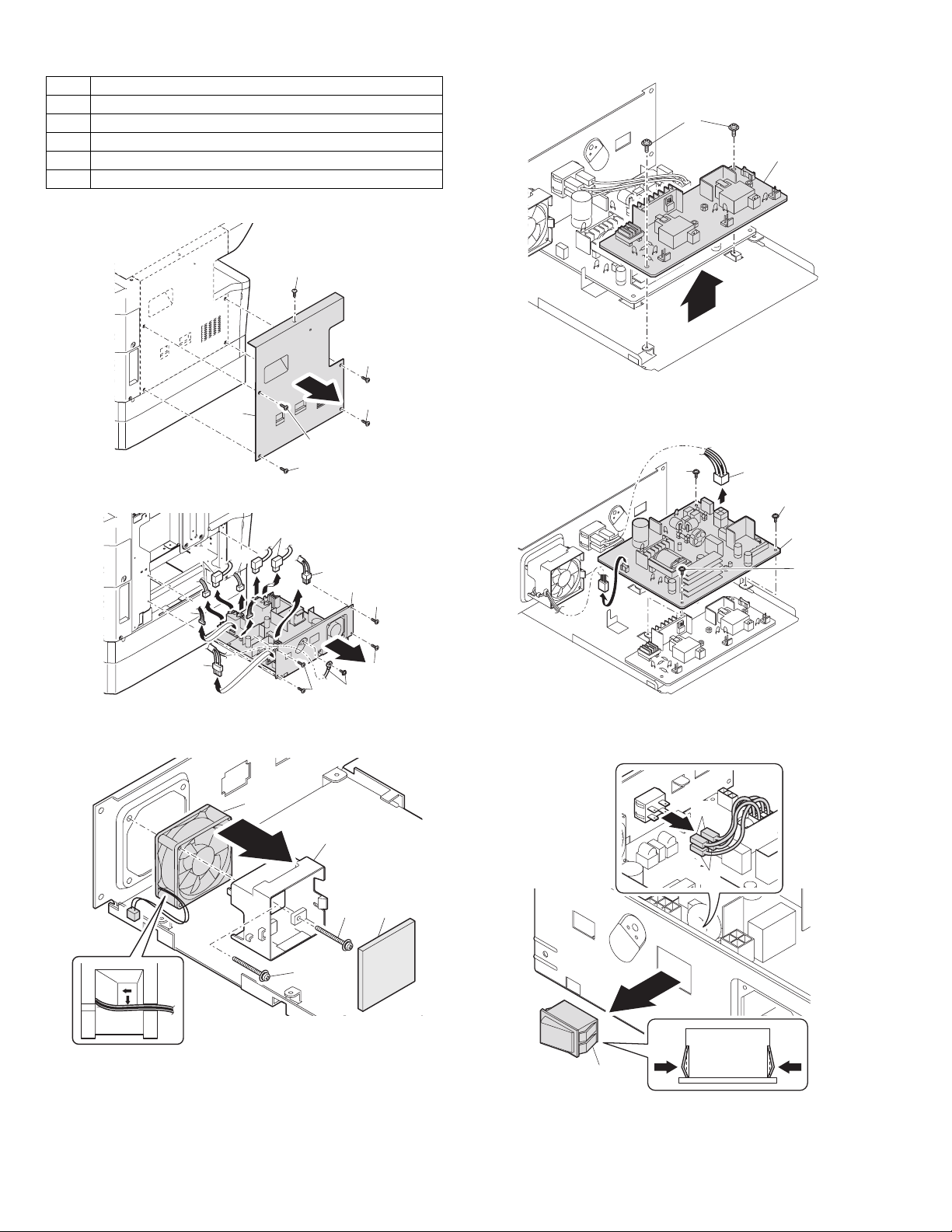
10.Power section
No. Content
A Power unit
BPower fan
C High voltage P.W.B.
DPower P.W.B.
EPower switch
A.Power unit
C. High voltage P.W.B.
(1)
(2)
(1)
(1)
B. Power fan
(2)
(2)
(2)
(2)
(2)
(4)
(2)
(1)
(1)
(1)
(2)
(3)
(2)
(3)
(1)
(1)
(1)
D. Power P.W.B.
E. Power switch
(2)
(1)
(2)
(3)
(2)
(1)
(2) (1)
(2)
AR-5520 DISASSEMBLY AND ASSEMBLY 11-13
(1)
(2)
Page 75

11.Developing section
No. Contents
A Developing box
B Developing doctor
C MG roller
A.Developing box
B.Developing doctor
C.MG roller
(1)
(5)
(4)
(3)
(2)
(3)
(2)
(1)
Adjustment: Developing doctor gap adjustment
(2)
(3)
Adjustment: MG roller main pole position adjustment
Note:Attach it to fit with the attachment reference when replacing the DV
blade.
Attaching
reference
0
0.5
AR-5520 DISASSEMBLY AND ASSEMBLY 11-14
DV blade
Page 76

12.Process section
No. Contents
A Drum unit
B Main charger unit
C Cleaning blade
A.Drum unit
When removing the drum, put the drum unit upside down to prevent
waste toner from spilling.
(1)
(2)
13.Others
No. Contents
AOperation P.W.B.
B Tray interface P.W.B.
C 2nd tray paper entry sensor / Paper empty sensor
D 2nd tray paper feed solenoid / Transport solenoid
E 2nd tray transport clutch
F 2nd tray transport roller
G 2nd tray paper feed clutch
H 2nd tray paper feed roller
I Main motor
J I/F P.W.B.
K Paper entry sensor
L Paper empty sensor
M Paper feed roller
A. Operation P.W.B.
When the drum is replaced, be sure to replace the drum positioning boss
with a new one, too.
B. Main charger unit
(1)
(2)
(1)
C.Cleaning blade
(5)
(6)
(5)
(5)
(5)
(4)
(3)
(3)
(1)
(7)
(2)
When installing a resistor, check to confirm that the terminal section is in
contact with the metal section of the cleaning blade.
AR-5520 DISASSEMBLY AND ASSEMBLY 11-15
Page 77

C. 2nd tray paper entry sensor / Paper empty sensor
(3)
(2)
(1)
(4)
(1)
(5)
(1)
(1)
(2)
B. Tray interface P.W.B.
(2)
(1) (1)
(1)
(3)
(3)
D. 2nd tray paper feed solenoid / Transport solenoid
(2)
(2)
(2)
(1)
(2)
(1)
(1)
(1)
(1)
(2)
(3)
(1)
AR-5520 DISASSEMBLY AND ASSEMBLY 11-16
Page 78

E.2nd tray transport clutch
G. 2nd tray paper feed clutch
Apply grease (FG-40H)
to the gray area
(UKOG-0004QSZZ).
F. 2nd tray transport roller
(1)
(2)
(2)
A
(2)
(1
(1)
(3)
Apply grease (FG-40H)
to the gray area
(UKOG-0004QSZZ).
H. 2nd tray paper feed roller
B
A
(1)
(1)
(2)
AR-5520 DISASSEMBLY AND ASSEMBLY 11-17
Page 79

I. Main motor
K. Paper empty sensor
(2)
(1)
J. Paper entry sensor
(3)
(2)
(1)
(3)
(2)
(1)
L. Paper feed roller
(1)
(3)
(2)
* When removing the paper feed roller, operate the paper feed clutch
with SIM 6-1, and keep the paper feed roller down as shown in the
figure above for operation.
(1)
(1)
(2)
AR-5520 DISASSEMBLY AND ASSEMBLY 11-18
Page 80

[12]FLASH ROM VERSION UP PROCEDURE
1.Preparation
Write the download data (the file with the extension dwl) to the main
body of AR-5516/AR-5520/AR-5516S/AR-5520S/AR-5516D/AR-5520D.
Necessary files for download
• Maintenance.exe (Maintenance software)
• ProcPegasus.mdl
• ProcPegasus.ini
• ProcPegasus.fmt
• Pegasus.inf
• Usbscan.sys
• Download file:***.dwl
<Note>
•The Download file(***.dwl ) and the like that are to be downloaded
should be copied, in advance, into folders that have a maintenance
program.
•When creating a folder for a maintenance tool in the PC, be sure that no
lengthy folder name is included in the path.
(Example)
Incorrect c:\Maintenance Download Tool
Correct c:\Maintenance\Downtool
2.Download procedure
1) Main body side:
Executable by performing the Service Simulation No. 49-01 (Flash
Rom program-writing mode).
(A word "d" appears on the operation panel to denote the download
mode status. )
3) PC side:
Boot the maintenance program. Select the model icon.
<Sample display>
4) PC side:
Confirm that the "Simulation Command List" tree is displayed on the
maintenance program.
5) PC side:
When the message "the main body has not got started running" is
displayed on the lowest area of the figure below after the
"maintenance program" is started up, select the "File" and then
"Reconnect" in the menu bar.
2) Connect the PC and the main body with the download cable
(USB cable).
6) PC side:
Confirm a tree is displayed under the "Special (MCU/IMC2/FAX)" on
the maintenance program". (If no tree is displayed, confirm that the
USB is connected and select the "Reconnect" (the above 5) again.)
AR-5520 FLASH ROM VERSION UP PROCEDURE 12-1
Page 81

7) PC side:
Double click "Special (MCU/MCU2/FAX)" in the main tree item to
develop the sub tree items, and double click "DWL Download" in the
sub tree items.
8) PC side:
Specify the download file (*.dwl).
9) PC side:
The download file is specified, download is automatically performed.
The AUTO PAPER SELECT indicator and START indicator will blink
approximately 15 seconds after the download file is specified.
10) PC side:
When the message below is displayed, download is completed.
Completion message: DOWNLOAD COMPLETED
12) After-process: Terminate the maintenance program, and turn on the
power of the main body.
After the download (data transmission) has been completed, exit the
software program. The USB cable can be removed at this point.
NOTE:
•For making a second connection with another machine, select the "File"
and "Reconnect" in the menu bar on the maintenance program at the
time of the USB being re-connected. Repeat the previous procedures
from the above 5).
* Forbidden actions while downloading (Important)
Failure in the download concerned may not allow you to conduct the
subsequent download procedures. Added care should be taken to avoid
having the situation below arise while downloading.
•Switching off the main body of AR-5516/AR-5520/AR-5516S/AR-
5520S/AR-5516D/AR-5520D.
•Disconnecting the download cable (USB cable).
* If the above inhibit item occurs during downloading:
Turn OFF and ON the power.
1) If "d" (which means downloading) is displayed on the operation
panel LED of the machine, perform downloading again.
2) If "d" (which means downloading) is not displayed on the operation
panel LED of the machine, turn OFF the power, and press and hold
the [Copy ratio display] key and the [READ-END] key and turn ON
the power. If, then, "d" (which means downloading) is displayed on
the operation panel LED of the machine, perform downloading
again.
If "d" is still not displayed, the MCU must be replaced.
NOTE (Important):
•Be sure that the power is not turned off and the USB cable is not
removed until the word "OFF" appears.
11) Main body side:
Wait until the word "OFF" appears on the operation panel.
The appearance of "OFF" indicates the completion of the download
(writing into ROM).
Turn the power off.
AR-5520 FLASH ROM VERSION UP PROCEDURE 12-2
3. Installation procedure
A. USB joint maintenance program installation
The driver is installed by plug and play.
B. Installation procedure on Windows XP
1) Machine side:
Executable by performing the Service Simulation No. 49-01 (Flash
Rom program-writing mode).
(A word "d" appears on the operation panel to denote the download
mode status. )
2) Connect the machine and the PC with a USB cable.
Page 82

3) Check that the following display is shown.
Select "Install from a list or the specific location" and press the NEXT
button.
4) Select "Include this location in the serch". If the retrieval area does
not include the folder which includes the maintenance tool driver
(Pegasus.inf), select "Browse"
If the folder path is properly shown, press the NEXT button to go to
procedure 7).
6) Check that the path to the folder which includes the maintenance
tool driver (Pegasus.inf) is shown, and press the NEXT button.
7)) Check that the following display is shown. Press the Continue
Anyway button.
5) Select the folder which includes the maintenance tool driver
(Pegasus.inf), and press the OK button.
(When the driver is included in the "C:\Pegasus" folder:)
8) When installation is completed, the following display is shown.
Press the Finish button.
The installation procedure (on Windows XP) is completed with the above
operation.
C. Installation procedure on Windows 2000
1) Machine side:
Executable by performing the Service Simulation No. 49-01 (Flash
Rom program-writing mode).
(A word "d" appears on the operation panel to denote the download
mode status. )
2) Connect the machine and the PC with a USB cable.
AR-5520 FLASH ROM VERSION UP PROCEDURE 12-3
Page 83

3) Check that the new hardware search wizard is shown. Press the
NEXT button.
4) Select "Serch for a suitable driver for my device" and press the
NEXT button.
7) Specify the folder which includes the maintenance tool driver
(Pegasus.inf), and press the OPEN button.
Check that the path to the folder which includes the maintenance
tool driver (Pegasus.inf) is properly displayed, and press the OK
button.
(When the maintenance tool driver is included in the folder of
"D:\Pegasus")
8) Press the NEXT button, and installation is started.
5) Select "Specify a location" and press the NEXT button.
6) Press the "Browse" button. Specify the folder which includes the
maintenance tool driver (Pegasus.inf)
9) When installation is completed, the following display is shown.
Press the Finish button.
The installation procedure of the joint maintenance program on Windows
2000 is completed with the above operation.
AR-5520 FLASH ROM VERSION UP PROCEDURE 12-4
Page 84

[13] ELECTRICAL SECTION
r
OPU PWB
Kronos2 ASIC
BGA 48 4pin
LSU
SDRAM
Simp:16MB
Dup+Esort :64MB
Flash ROM
16bit
Shift -
POWER SUPPLY
5VEN,24V
HVU
COIN VENDOR/ A UDITOR
SPF/ RSPF
USB2.0
High Speed
DEV IC E
or
USB- NIC
Card
Reg
DCDC
Clock
Gen.
Reg
DCDC
DC- DC
1.Block diagram
7seg LED
LED
)
3.3V
)
)
)
Expansion IO
Expansion IO
Expansion IO
SCAN1-6(
PSW(
PSL,ONL(
(1M*16bit)
Reg. 2 pcs
3.3V
Driver
SPFMOTOR
CCFL
SPMT0/1/2/3
Driver
SPFCLH
SPFPSOL
Lamp
Invertor
24V
Sensor
Selector
L1,2
/SPFCOVER,PAPER,
SPFOPEN,/SPFOUT
HOME
POSITION
W0,1,2,3
SENSOR
(D
TRAY DETECTION,
PAPER DETECTION,
PAPER PASS DETECTION,
Feed SOL , Pick up SOL
FSOL
CPU
H8S/2321
( Wait)
Y1
PSOL
(24.576MHz)
A[19…1]
DOOR DETECTION
SELIN1,2,3
OP-CLK
OP-LATCH
OP-DATA
D[15…0]
SELIN1,2,3
OP-BEO
2Mb(128k*16bit)
SRAM
KEYIN
2nd TRAY
UART
PWM
MHPS
CLON
ASIC Reset
3.3V
Reset IC
)
5V,3.3V
8bits ( MSB/LSB)
V3.3V5AV5
AD
AFE(AD9826)
M
A
C
B/W
CCD
16bit
P
X
G
C
D
S
(TCD1710)
5V
ADCCLK,SYNCH,
BSAMP,VSAMP
SDI,SCLK,LOAD,OBE
MODE
TG3
Ø
TG2,
Ø
TG,
Ø
2,
Ø
1,
Ø
CCD Driver
LVTT L
1L
Ø
CLB,
Ø
RB,
Ø
1.2V
5v
MCU-PWB
SCAN:16MHz
sequencer
CPU:24.576MHzSS-ON
(B
3.3V 3.3V
LSU/SYSTEM:20.309MHz
USB:48MHz
Tender: 128MB
(Max. 4-chip composition)
MasterCLK(14.7MHz)
CCD PWB
Scanner Unit
KEY
3.3V
HC151
START KEY
detection
*Support for DEV-Initial
Buzzer
CRUM
4K 16kbyte
EEPROM
SSCG
CPU CLK
PMCLK(2078.74(Hz))
PMD
Expansion IO ASIC
MM_BI0/BI1/PH_B
MM_AI0/AI1/PH_A
TM+,TM-
HC151
/MMD
LED
(24.576MHz)
* Supplied from ClockGen
/VIDEO
S/H
Loads
Other
APCSTT
MPFS,RRS,
Driver
Driver
/MMRDY
/MMRDY
/CV_COPY
/CV_COUNT,/CV_START,/CV_CA,
TC, GRID, MC, BIAS
/POFF,HL,PR
FW
/SYNC
Mirror Motor
MainMotor Toner Moto
CPFS1
SGS, SRRC , SPUS , SPPS ,
VFMCNT, VFM, MPFS, CPFS2 ,
/CV_DPX,/CV_SIZE0,1,2,3
FAN
for ozone
Countermeasures
Inputs
Other
SPPD
INTERRUPT
I/O
CPU
CPU
RTH DRST
AR-5520 ELECTRICAL SECTION 13-1
Page 85

2.Actual wiring diagram
ACTUAL WIRING DIAGRAM 1/7
POLYGON
MOTOR
MCFBGRIDMC
GB .MCFB HARNESS
APC-BD-
MC HARNESS
PWB
TC HARNESS
B3P-VH(BLACK)#250
B07B-PARK
(RED)
HVU
TC
#250
7
BC HARNESS
BC
INLET HARNESS
AC CORD
B03P-VL-LF(WHITE)
B04P-VL-
LF (WHITE)
B2P3-VH-LF
(WHITE)
230V ONLY
AC SW HARNESS
DH PS HARNESS
JAPAN ONLY
AC SWITCH
DEHUMIDIFIER
HEATER
SWITCH
B03B-XASK-
B15B-XASK-LF
(WHITE)
POWER PWB
15
LF
(WHITE)
B02P-VT-LF
(RED)
B02P-NV
B02P-NV
BIAS
GP1S58
MIRROR HP SENSOR
CCD PWB
COPY LAMP
MIRROR MOTOR
OPTICAL BASE PLATE
OPE-MCU FFC
FFC 1mm
22
22FMN
(BLACK)
SPF GROUND WIRE
SPF UN
ORIGINAL TRAY HARNESS
SCANNER HP HARNESS
SENSOR HARNESS
USB2.0
B06B-PARK
(RED)
USB PWB
B26B-PUDSS
(WHITE)
CCD-MCU FFCCL FFC
22
3
B03B-PH
(RED)
D-SUB25
32
4
04FE-BT-VK-N
4
B04B-PH
B04B-PASK×2(WHITE)
4
4
22FMN-BTRK-A(BLACK)
LSU
(UNIFICATION)
FE4-32-S15D3-FA
(WHITE)
(WHITE)
B6B-PH
USB INTERFACE
HARNESS
5
B06B-PASK
B12B-XASK-1
(WHITE)
6
HARNESS
DUP P-OUT
GP1S58
(WHITE)
B20B-PUDSS-1
(WHITE)
MCU-PWB
B5B-PH
(WHITE)
12
GP1S58
2
B2B-XH-A-K
(BLACK)
20
B3B-PH
(BLACK)
B3B-PH
(BLACK)
5
LSU-MCU
HARNESS
B12B-PASK
(WHITE)
B3B-PH
(RED)
B2B-XH-A-R
(RED)
B2B-XH-A-S
(WHITE)
B3B-PH
B3B-PH
(WHITE)
B3P-VH
B13B-PH
(WHITE)
B2P-VH
B05B-PASK
B3B-PH
(WHITE)
3
3
HARNESS
PS HARNESS
22
(WHITE)
B22B-PUDSS-1
B4B-PH
(RED)
3
PSOL
2
2
PICK UP
SOL
3
B4B-PH
(WHITE)
3
(BLACK)
22
(WHITE)
13
2
(WHITE)
(WHITE)
46
B4B-PH
(WHITE)
4
B04B-PASK
(WHITE)
HAND SOLENOID HARNESS
SIDE COVER SW
HARNESS
AUDITOR
OPTION
TONER
MOTOR
MAIN MOTOR
HARNESS
MAIN
MOTOR
CRM MCU
HARNESS
VLR-02V
TRAY DEHUMIDIFIER
P-IN HARNESS
PALR-02V
HANDEMPHARNESS
CASSETTE EMP
HARNESS
CASSETTE SW
HARNESS
DEV HARNESS
HL HARNESS
HEATER
PAP-02V-S
3
2
OZON FAN
JAPAN ONLY
FRONT COVER SWITCH
DV UNIT
SRU
1st TRAY
OR
D2X GP1A73 GP1S58 GP1S73
2nd TRAY
OR
MULTI CASETTE
VLR-02V
SIDE COVER SWITCH
OPERATION PANEL
COPY OP PWB
18
DUP MOTOR
DRUM INITIAL SW
CRU MODEL ONLY
DRUM SW
COOLING FAN
PAPER OUT
SENSOR
COOLING FAN
DUP
SENSOR
OPTION COIN VENDER
AR-5520 ELECTRICAL SECTION 13-2
THERMISTER
HEATER LAMP
FUSING HARNESS
Page 86

ACTUAL WIRING DIAGRAM 2/7
LSU UNI
(
1
PKBLGY
TONER MOTOR
BKPKBK
1
22
MCU PWB
DUP SENSOR PWB
2
3
TMB_O
DGND
< DUP P-OUT HARNESS >
BLGYPKBLGY
345
1
2
CN118(B6B-PH-K-S)
(PDPX)
PAPER OUT SENSOR PWB
1236
PKBLGY
)TUOP(DNGD (POUT)
FUSER
124
DNGDDMP/ DGND
TNCMFV/V42
CN138(B04B-PASK-1)
VFMOUT
COOLING FAN
PGND
VFM1_LOCK
FUSER
COOLING FAN
12433
TUOMFVV42
OZON FAN
2
3
1
KCOL_MFNZO1_TMD/
TUOMFNZO0_TM
DNGP2_TMD/
CN115(B03B-PH-K-K)
)1-KSAP-B50B(721NCKSAP-B50B
< LSU-MCU HARNESS >
D/
/PMRDY
/PMCLK
3
1
457
9
10
11
/PSRSOL
2121
CN123(B2B-XH-A-RD)
RD
PS SOL
CN124(B2B-XH-S) CN139(B04B-PASK-1)
RD
PICK UP SOL
2
1
BL
CN114(B5B-PH-K-S)
BL
/DMT_3
3
4
5
1
2
4
5
113
2
DGND
234
CN119(B4B-PH-K-S)
PKBLGY
1
RDWHBL
3
RDWHBL
321
CN116(B3B-PH-K-S)
(CASETTE)
1
2
BL
GY
3
CN129(B3B-PH-K-K)
(DRUM)
1
2
3
DUPLEX MOTOR
< MAIN MOTOR HARNESS >
5
2
3
< P-IN HARNESS >
RDWHBL
1
2
3
175767-3 CN121(B3B-PH-K-R)
< CASETTE EMP HARNESS >
RDWHBL
3
175767-3 CN120(B3B-PH-K-K)
< HANDEMP HARNESS >
PKBLGY
4
322
1
1
< CASETTE SW HARNESS >
BL
2
1
1
15778-2
(CRUM MODEL ONLY)
< DRUM SW HARNESS >
GY
2
1
2
15778-2
)
p-off 5Vp-off
/MMCLK /MMCLK
/MMRDY /MMRDY
/MMD /MMD
PGND PGND
INT24V INT24V
5Vp-off 5Vp-off
(HPEMPTY) (HPEMPTY)
DGND N.C
UNIFICATION
T
(PIN) (PIN)
5V
5Vp-off 5Vp-off
(CPEMPTY) (CPEMPTY)
DGND DGND
(CASETTE) N.C
DGND DGND
(DRUM) N.C
DGND DGND
DGND DGND
MAIN MOTOR
MOTOR
CZHR-08V-S CN108(B12B-PASK-1) CN131(B2P-VH)
APC
2
1
3
GND O_AMTDNGD
SHOLD (SHOLD) 5Vp-off
/VIDEO (VIDEO#) (PDPX)
8 847665
SW5V (LPSEL)
LPSEL DNGDCNYS/
/SYNC ffo-pV5V42 5Vp-off
N.C off-pV5V5TNI
APCSTT (/LDEN)
4
5
177622-5
24V TNCMFV/LOSPC/
P-GND VFM2_LOCK
PM PWB
/PMD PGND
123
/PMRDY
/PMCLK 24Vdup
HAND PAPER EMPTY SENSOR PWB
PAPER IN SENSOR
CASETTE SWITCH
CASETTE EMPTY SENSOR
AR-5520 ELECTRICAL SECTION 13-3
Page 87

ACTUAL WIRING DIAGRAM 3/7
GP1A71A1
3
5V
3
1
CN3(B07B-PASK) PHR-6
NEW
< RSPF/SPF BRANCH HARNESS >
SPFOPEN(BOOK SENSOR)
1
2
1
2123
SPFOPEN
CN1(B03B-PARK) DF-3S-2C
A/A/
1
2
PULSE
MOTOR
B/B/
6
425
3
4
L1
L2
2W2W2W
3W3W3WC.N
1W1W1W
OWOWOW
V5V5V5
SENSOR PWB
PAPER FEED UNIT
1V42C.N
1V421V42
NEW
<SENSOR HARNESS>
5
6
7
24V1
CN6(B20B-PUDSS) PALR-07V B7B-PH-K-S
123
22
1
1
1
567
4
463
55
3
4
9
785
3
SPF PSOL
11
22
77
PAP-07V-S
6
PALR-02V
6
11
14
20
PAP-02V-S
321
DF3-3S-2C
ORIGINAL TRAY
NEW
<ORIGINAL TRAY HARNESS>
PALR-06VF
11
2
DF3-3S-2C GP1A71A1
22
33
5101
16413
321
445566
714
S
123
PHR-3
PAP-06V-S GP1A71A1
8
PAPER ENTRY SENSOR
18
SPF GSOL
SPF RSOL
V-N
1
2
DSPF ONLY
1
2
SMP-02V-NC
<SPF PWB EARTH HARNESS >
12
2
LOSG/HLC/
1V42C.N
CN4(B2B-PH-K-S)
19
10
)C42-S0169-ASMI(2NC)A-KRTB-NMF22(601NC
LSP/LSP/DNGDDNGD
3CCV3CCV
3CCV3CCV
WSPWSP SGND
DGNDDNGD
12345
< OPE-MCU FFC >
1
2
3
456
MCU PWB
323130
SPF INTERFACE PWB
CN5(B26B-PUDSS)
24V REVOCFPSREVOCFPSREVOCFPS
24V DNGSDNGSDNGS
25
262316
SPMT3#
SPMT2#
6
18
SPMT0# LOSPFPSLOSP/
(SELIN3B) 1V421V42
(SELIN2B)
(PDOWNA)
SPFRSOL
7
5
212017
2
9
24
11
3
14
12
13115
19
22
CN7(B3B-PH-K-S) SMR-02
311
/SPFOUT
SGND
1
2
3
CN2(B3B-PH-K-K)
OP PWB
)EBORTS_PO()EBORTS_PO(2IHP_DCC2IHP_DCC
)A1NILES()A1NILES(0BD_EFA0BD_EFA
)A2NILES()A2NILES(1BD_EFA1BD_EFA
)A3NILES()A3NILES(2BD_EFA2BD_EFA
)1NACS()1NACS(3BD_EFA3BD_EFAAA)2NACS()2NACS(4BD_EFA4BD_EFA
NIYEKNIYEKEDOMEDOM
7
6
7
)3NACS()3NACS(5BD_EFA5BD_EFA
8
9
101311
12
8
9
101112
28
29
2524232221
27
26
)4NACS()4NACS(6BD_EFA6BD_EFABB)5NACS()5NACS(7BD_EFA7BD_EFA
13
)6NACS()6NACS(KCS_EFAKCS_EFA
141516
)KLC_PO()KLC_PO(DNGDDNGD
16
)HCTAL_PO()HCTAL_PO(KLCDAKLCDA
)ATAD_PO()ATAD_PO(NES_EFANES_EFA
171415
18
171819
19
20
)KLC_RZB()KLC_RZB(1IHP_DCC1IHP_DCC
LNO/L
19
20
20
NO/DNGDDNGD
181716
2
3
DNGDDNGD1DS_EFA1DS_EFA
21
22
< SPF HARNESS > NEW
123
4
21
22
CN110(DBR40-251F100)
PC_DCCPC_DCC
SR_DCCSR_DCC
GT_DCCGT_DCC
PMASBPMASB
DNGDDNGD
14
15
131211
10
56789
)B3NILES(V21V21
)B2NILES(V21V21
#3TMPS3CCV3CCV
V42PMASVPMASV
V42DNGDDNGD
9
8
765
)ANWODP(DNGDDNGD
#0TMPSDNGDDNGD
#2TMPSffo-pV5ffo-pV5
432
101112
LOSRFPSDNGDDNGD
SPFPSOL SPFPSOL
1
131415
16
)REVOCFPS/(DNGP (/SPFCOVER) 2L2L
PGND PGND
DGND DGND V5V5
DGND DGND 1L1L
PGND PGND DNGSDNGS
(YSPF) (YSPF) V5V5
1
CN111(04FE-BT-VK-N)
171819
)NEPOFPS()NOLC( (SPFOPEN)
#1TMPS)LC( SPMT1# DNGSDNG
234
212223
20
)TUOPFPS/(V42 (/SPFPOUT)
(SELIN1B) (SELIN1B) PULL UP
SPFCLH SPFCLH SGND
SPFGSOL SPFGSOL PAPER
(PDOWNB) (PDOWNB)
24
25
5V 5V
(SPFPAPER) (SPFPAPER) LOSRFPSLOSR/
MHPS
5Vp-off 1V421V42
2
1
CN112(B3B-PH-K-R)
DGND 24V1
3
SPF CLH
DF3-3S-2C
<SPF PAPER EXIT SENSOR HARNESS>
/SPFOUT
CN113(B4B-PH-K-S)
(PAPER EXIT SENSOR)
OUT_B+ 5V
OUT_A+
1
2
GP1A71A1
OUT_A-
OUT_B-
3
4
OPTICAL UNIT
CCD PWB
< CCD-MCU FFC >
567
123
4
CN1(FF4-32-S15D5) CN109(FF4-32-S15D3-FA)
< CL FFC >
8
9
10
11
121314
15
161718
31
272829
232425
19
20
21
26
22
32
30
UNIT
COPY LAMP
< SCANNER HP HARNESS >
Mirror HP
SENSOR PWB
MIRROR MOTOR
AR-5520 ELECTRICAL SECTION 13-4
Page 88

ACTUAL WIRING DIAGRAM 4/7
143
2
y
AC SW
< AC SW HARNESS >
BKWHBK
WH
1
243
P/S PWB (1/3)
123
4
567
PS FAN
CN102(B03B-XASK-LF)
8
AC CORD
< INLET HARNESS >
2
3
1
CN001(B03P-VL-LF)
PR
9
10
11
12
13
230V Onl
3
1
215
F-GND
Holder
TC high
voltage
781#052#
#187
CTCT
< TC HARNESS >
WH
2
CBCB
< BC HARNESS >
RD
1
TCS
Socket
Holder
14
MCFB HARNESS >
.
< MC HARNESS >
< GB
PK
BK
WH
132
AEH)L(RETAEH
1
2
P/S PWB (2/3)
BK
WH
< HL HARNESS >
2
1
VLR-02V CN002(B02P-VT-LF)
2
1
< PS HARNESS >
8
/POFF /POFF NEUTRAL in
CN107(P22B-PUDSS-1) CN101(B15B-XASK-LF) CN004(B04P-VL-LF)
MCU PWB
234
1
#250
MC
BFCMGRIDL
C.NBIAS
CN3(B3P-VH(BLACK)
GRIDDNGP
C.NDNG-F
CN4(B02P-NV(RED))
HVU PWB
/MC
/TC
4
2
3
5
1
CN1(B07B-PASK)
9
10
24VIN 24VIN LIVE in
24VIN 24VIN NEUTRAL out
15
16
17
11
13
14
12
5VIN 5VIN LIVE out
5VIN 5VIN
DGND DGND
DGND DGND
PSFMOUT PSFMOUT
18
PSFMLOCK PSFMLOCK PSFMOUT
PGND PGND PSFMLOCK
PGND PGND GND
PGND PGND
202119222
PR
3
4
1
FW FW LIVE
HL OUT HL OUT N.C
/MC NEUTRAL
/TC
GRIDL
/BIAS
6
7
5
PGND
INT24
(TCCNT-AN)
INT24
6
DV BIAS
(TCCNT-AN)
7
1
2
CN2(B02P-NV)
B4B-PH-K-S
DV UNIT
52025-0811 51010-0811
256
8
1
DV BIAS
2
56347
8
1
RDPLBR
GY
< DEV HARNESS >
RDPLBR
GY
1
2
3
CN126(B4B-PH-K-S)
24V 24V
(TCS) (TCS)
(DVS1) (DVS1)
PGND PGND
CRUM
3
N.C
1
4
7
N.C
N.C
2
TSHP-04V-K
1
2
ORLBPK
< CRM-MCU HARNESS >
ORLBPK
CN128(B04B-PASK-1) TSHR-04V-K
(SDA_CRUM) (SDA_CRUM)
(SCL_CRUM) (SCL_CRUM)
3
3
1
VCC3 VCC3
4
HAND PAPER
PICK UP SOL
4
GY
22
LOSPH/HPSOL/
V42V42
1
< HAND SOLENOID HARNESS >
GY
ORPLBK
4
DGND DGND
2
1 1
CN122(B2B-XH-K-K) B02B-PASK
HL
THERMOSTAT
< FUSING HARNESS >
THERMISTER
< THERMISTER HARNESS >
BK
2
3
1
CN135(B3B-PH-K-S) #250 #250
N.C )L(RET
RTH_IN
DGND )N(RETAEH)N(RETAEH
AR-5520 ELECTRICAL SECTION 13-5
Page 89

ACTUAL WIRING DIAGRAM 5/7
123
4
+DtnoC_BSUtnoC_BSU
D-
CN501(UBR23-4K2200)
GND+D_NBSU+D_NBSU
USB PWB
)2-KSAP-B60S(005NCCN102(B06B-PASK-1)
12354
Front Side Cover SW
SW
Shell5
Shield-D_NBSU-D_NBSU
6
< SIDE/FRONT COVER SWITCH HARNESS >
Side Cover SW
SW
MCU PWB
< USB HARNESS >
1
VCC3 SUBV3CCV
263
Vbus Vbus
RD
RD
CN101(B3P-VH)
123
V
N.C
24
INT24V(DSWS)
4
GND GND
AR-5520 ELECTRICAL SECTION 13-6
Page 90

ACTUAL WIRING DIAGRAM 6/7
(OPTION)
COIN VENDER
567
4
CV_COUNT
/CV_START
/CV_CA
8
9
0EZIS_VC/V42V42
XPD_VC/V42V42
N.C
123
24V
P-GND
/CV_COPY
CN133(B12B-XASK-1)
MCU PWB
101112
1EZIS_VC/)1LCSP()1LOSP(
2EZIS_VC/)1LOSF()1LOSF
3EZIS_VC/)2LCSP()2LOSP(
)3LCSP()3LOSP(
)2LOSF()2LOSF(
)3LOSF()3LOSF( CN134(B13B-PH-K-S)
AUDITOR
(OPTION)
123456789
YDAER_DUA/DNGDDNG-D
YPOC_DUA/DNGPDN
CNP_DUA/DNGPDNG-P
AC_DUA/DNGDDNG-D
DNGP)3Y(3Y
DUA/)1Y(1Y
V42)C1NILES(C1NILES
V5)2Y(2Y
DH3
DH4
ONLY FOR JAPAN
A-1
A-1
A-2
A-2
OPTION CASETTE ONLY FOR JAPAN
L-HDL-HD
N-HDN-HD
DH-L
A-2
A-2
A-2
DH-N
A-1
A-2
(ELP-02V) (ELR-02VF)
(ELP-02V) (ELR-02VF) (ELP-02V) (ELR-02VF)
DH2
A-1A-1
DEHUMIDIFIER HEATER
(PWB PATTERN ONLY)
123
12
13
10
11
)a_CNP/(ffo-pV5V5
CT_DUA/)C3NILES(C3NILES
C.N)C2NILES(C2NI
V42ffo-pV5V5
DGND
4
+24V
N,C
N,C
/DHROFF
CN130(B4B-PH-K-R)
A-1
DH1
A-2
A-2A-2
A-2
A-2
A-1
N-HDN-HD
A-1
L-HDL-HD
A-1
F)
A-1
OR
TO 2ND CS UNIT
123456789
<CS-MCU HARNESS>
239
1
MULTI CS UNIT
(B22B-PUDSS) CN132(B20B-PUDSS)
16
13
14
111022
15
17
201218
LES
181920
13
15
14
16
N.C
N.C
101112
4
19
17
(
8
5
6
7
21
G-P
DEHUMIDIFIER HEATER SWITCH
< DH PS HARNESS >
BK
L-HDL-HD
DH-N
A-1
A-1
A-2
B
(172074-1) WHITE
B
WH
3
1
(ELP-02V) (ELR-02VF) (ELP-02V) (ELR-02VF)
(ELP-02V) (ELR-02V
AR-5520 ELECTRICAL SECTION 13-7
LIVE LIVE
CN003(B2P3-VH-LF) (172074-7) RED
PS PWB (3/3)
NEUTRAL
Page 91

ACTUAL WIRING DIAGRAM 7/7
WEIVERAERTINUTINUSCDN2
WEIVERAERTINUTINUSCITLUM
CSS1
PPD1
PUDP-20V-S
DRS1
TO 2ND OR MAIN BODY
5Vp-off
5Vp-off
(Y3)
(Y2)
(Y1)
DGND
DGND
PGND
PGND
(FSOL3)
(PSCL3)
(FSOL2)
(PSCL2)
(FSOL1)
(PSCL1)
24V
24V
(UPPER UN)
(SELIN3C)
(SELIN2C)
(SELIN1C)
PWB
PSOL1
FSOL1
20
19
18
17
16
15
14
13
12
11
10
9
8
7
6
5
4
3
2
1
CASS1
< CS-MCU HARNESS >
HEATER DH1
1
22
(UPPER UN)
TO 2ND OR MAIN BODY
1
2
ELP-02V ELR-02V
JAPAN ONLY ELP-02V
N.C
16
N.C
14
5Vp-off
15
5Vp-off
13
(SELIN3C)
18
(SELIN2C)
12
(SELIN1C)
20
(Y3)
22
(Y2)
10
(Y1)
11
DGND
8
DGND
7
PGND
6
PGND
5
(FSOL3)
21
(PSCL3)
17
(FSOL2)
19
(PSCL2)
4
(FSOL1)
9
(PSCL1)
3
24V
2
24V
1
CS INTERFACE PWB
2ND CS
CN-A(B22B-PUDSS)
FOR LOWER OPTION CS
DH-L
1
1
ELR-02V
5Vp-off
5Vp-off
(SELIN3C)
(SELIN2C)
(SELIN1C)
N.C
(Y2)
(Y1)
DGND
DGND
PGND
PGND
N.C
N.C
(FSOL2)
(PSCL2)
(FSOL1)
(PSCL1)
24V
24V
CN-C(B20B-PUDSS)
2
20
19
18
17
16
15
14
13
12
11
10
9
8
7
6
5
4
3
2
1
CSS1
PPD1
PUDP-20V-S
DRS1
TO 2ND OR MAIN BODY
(UPPER UN)
5Vp-off
5Vp-off
(SELIN3C)
(SELIN2C)
(SELIN1C)
(Y3)
(Y2)
(Y1)
DGND
DGND
PGND
PGND
(FSOL3)
(PSCL3)
(FSOL2)
(PSCL2)
(FSOL1)
(PSCL1)
24V
24V
PWB
FSOL1 PSOL1
20
19
18
17
16
15
14
13
12
11
10
9
8
7
6
5
4
3
2
1
CASS1
< CS-MCU HARNESS >
1
ELP-02V
PSOL2
CASS2
PPD2 CSS2
JAPAN ONLY
NC
16
NC
14
5Vp-off
15
5Vp-off
13
(SELIN3C)
18
(SELIN2C)
12
(SELIN1C)
20
(Y3)
22
(Y2)
10
(Y1)
11
DGND
8
DGND
7
PGND
6
PGND
5
(FSOL3)
21
(PSCL3)
17
(FSOL2)
19
(PSCL2)
4
(FSOL1)
9
(PSCL1)
3
24V
2
24V
1
CN-A(B22B-PUDSS) LOWER UNIT
HEATER DH2
UPPER CS
1
22
(UPPER UN)
TO 2ND OR MAIN BODY
ELR-02V
DH-L
1
2
ELP-02V
CS INTERFACE PWB
MULTI CS
CN-C(B20B-PUDSS)
HEATER DH2
LOWER CS
2
11
ELR-02V
2
ELP-02V
5Vp-off
5Vp-off
(SELIN3C)
(SELIN2C)
(SELIN1C)
N.C
(Y2)
(Y1)
DGND
DGND
PGND
PGND
N.C
N.C
(FSOL2)
(PSCL2)
(FSOL1)
(PSCL1)
24V
24V
20
19
18
17
16
15
14
13
12
11
10
9
8
7
6
5
4
3
2
1
PSOL2
11
22
/PSOL1
12311
CN-B(B16B-PUDSS)
< ONE-STAGE TRAY HARNESS >
1
2
24V
/PSOL1 24V
1
2
SMR-02V-N SMP-02V-NC
SMR-02V-B SMP-02V-BC
PSOL1
24V 24V
FSOL1
422
/FSOL1 /FSOL1
175778-2
1 13
CASS1 CASS1
CASS1
9
2
D-GND D-GND
DRS1
14
15
DF3-3S-2C
1
D-GND CSS1 DH-L
16
2
PPD1 PPD1 DH-N
PPD1
113
5V 5V
8
12
DF3-3S-2C
123
D-GND
DRS1 N.C DH-N
5V N.C
DRS1
N.C
567
10
DF3-3S-2C
123
D-GND N.C DH-L
5V N.C
CSS1 N.C DH-N
CSS1
/PSOL1
1
2
CN-B(B16B-PUDSS)
<TWO-STAGE TRAY HARNESS>
2
11
24V
/PSOL1 24V
2
SMR-02V-N SMP-02V-NC UPPER UNIT
SMR-02V-B SMP-02V-BC
PSOL1
UPPER UNIT
3
4
22
1
24V 24V
/FSOL1 /FSOL1
FSOL1
13
175778-2
1
CASS1 CASS1
CASS1
D-GND D-GND
DRS1
14
15
DF3-3S-2C
112 9
D-GND CSS1 DH-L
2 16
PPD1 PPD1 DH-N
PPD1
3 11
5V 5V
8
12
DF3-3S-2C
1
2
3
D-GND
DRS1 CASS2 DH-N
DRS1
CSS2
10
5V PPD2
7
5
6
DF3-3S-2C
2
3
1
D-GND 24V DH-L
CSS1 /PSOL2 DH-N
5V N.C
CSS1
SMP-08V-NC
SMR-08V-N
<MULTI-STAGE HARNESS 2>
LOWER UNIT
222
111
2SSAC2SSAC
D-GND
D-GND
CASS2
2LOSP/2DP
V42
SMP-02V-NC SMR-02V-N
33
44
55
66
77
88
2SSC2SSC
V5V5
V5V5
D-GND
D-GND
P2DPP
312
1
2
D-GND
PPD2
3
D-GND
CSS2
AR-5520 ELECTRICAL SECTION 13-8
Page 92

LEAD-FREE SOLDER
The PWB’s of this model employs lead-free solder. The “LF” marks indicated on the PWB’s and the Service Manual mean “Lead-Free” solder.
The alphabet following the LF mark shows the kind of lead-free solder.
Example:
<Solder composition code of lead-free solder>
Solder composition
Sn-Ag-Cu
Sn-Ag-Bi
Sn-Ag-Bi-Cu
Sn-Zn-Bi
Sn-In-Ag-Bi
Sn-Cu-Ni
Sn-Ag-Sb
Bi-Sn-Ag-P
Bi-Sn-Ag
5mm
Lead-Free
Solder composition
code (Refer to the
table at the right.)
a
(1) NOTE FOR THE USE OF LEAD-FREE SOLDER THREAD
When repairing a lead-free solder PWB, use lead-free solder thread.
Never use conventional lead solder thread, which may cause a breakdown or an accident.
Since the melting point of lead-free solder thread is about 40°C higher than that of conventional lead solder thread, the use of the exclusive-use
soldering iron is recommendable.
Solder composition code
a
b
z
i
n
s
p
(2) NOTE FOR SOLDERING WORK
Since the melting point of lead-free solder is about 220°C, which is about 40°C higher than that of conventional lead solder, and its soldering capacity is
inferior to conventional one, it is apt to keep the soldering iron in contact with the PWB for longer time. This may cause land separation or may exceed
the heat-resistive temperature of components. Use enough care to separate the soldering iron from the PWB when completion of soldering is
confirmed.
Since lead-free solder includes a greater quantity of tin, the iron tip may corrode easily. Turn ON/OFF the soldering iron power frequently.
If different-kind solder remains on the soldering iron tip, it is melted together with lead-free solder. To avoid this, clean the soldering iron tip after
completion of soldering work.
If the soldering iron tip is discolored black during soldering work, clean and file the tip with steel wool or a fine filer.
Page 93
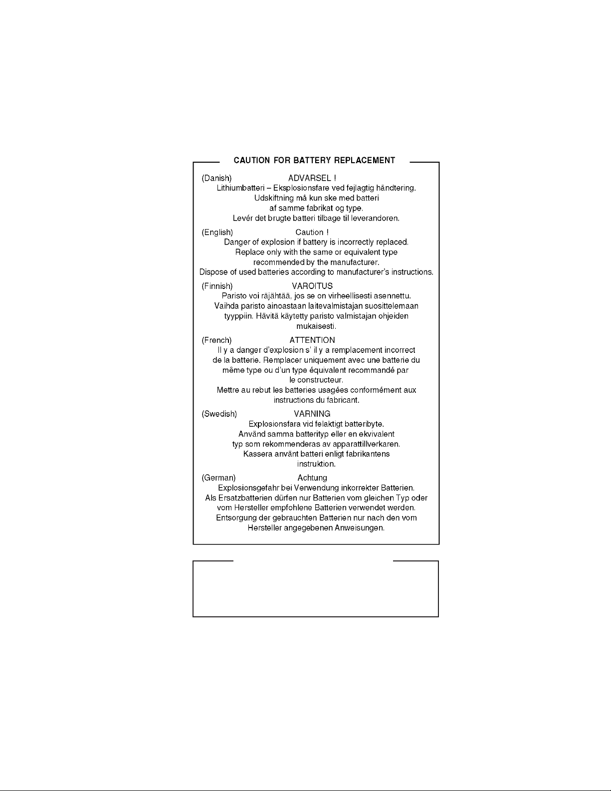
(For USA,CANADA)
CAUTION FOR BATTERY DISPOSAL
Contains lithium-ion battery. Must be disposed of properly.
Remove the battery from the product and contact
agencies for information on recycling and disposal options.
federal or state environmental
Page 94

c
c
COPYRIGHT 2008 BY SHARP CORPORATION
No part of this publication may be reproduced,
No part of this publication may be reproduced,
No part of this publication may be reproduced,
electronic, mechanical, photocopying, recording, or otherwise,
electronic, mechanical, photocopying, recording, or otherwise,
electronic, mechanical, photocopying, recording, or otherwise,
without prior written permission of the publisher.
without prior written permission of the publisher.
without prior written permission of the publisher.
Trademark acknowledgments
Trademark acknowledgments
Trademark acknowledgments
Windows and Windows NT are trademarks of Microsoft Corporation in the U.S.A.
Windows and Windows NT are trademarks of Microsoft Corporation in the U.S.A.
Windows and Windows NT are trademarks of Microsoft Corporation in the U.S.A.
and other countries.
and other countries.
and other countries.
IBM and PC/AT are trademarks of International Business Machines Corporation.
IBM and PC/AT are trademarks of International Business Machines Corporation.
IBM and PC/AT are trademarks of International Business Machines Corporation.
PCL is a trademark of Hewlett-Packard Company.
PCL is a trademark of Hewlett-Packard Company.
PCL is a trademark of Hewlett-Packard Company.
Pentium is a registered trademark of Intel Corporation.
Pentium is a registered trademark of Intel Corporation.
Pentium is a registered trademark of Intel Corporation.
All other trademarks and copyrights are the property of their respective owners.
All other trademarks and copyrights are the property of their respective owners.
All other trademarks and copyrights are the property of their respective owners.
c
All rights reserved.
All rights reserved.
All rights reserved.
Printed in Japan.
Printed in Japan.
Printed in Japan.
stored in a retrieval system, or transmitted,
stored in a retrieval system, or transmitted,
stored in a retrieval system, or transmitted,
in any form or by any means,
in any form or by any means,
in any form or by any means,
SHARP CORPORATION
SHARP CORPORATION
SHARP CORPORATION
Digital Document System Group
Digital Document System Group
Digital Document System Group
CS Promotion Center
Yamatokoriyama, Nara 639-1186, Japan
Yamatokoriyama, Nara 639-1186, Japan
Yamatokoriyama, Nara 639-1186, Japan
2008 September Printed in Japan
N
N
N
 Loading...