

Page 1
CODE : 00ZAR5320/A2E
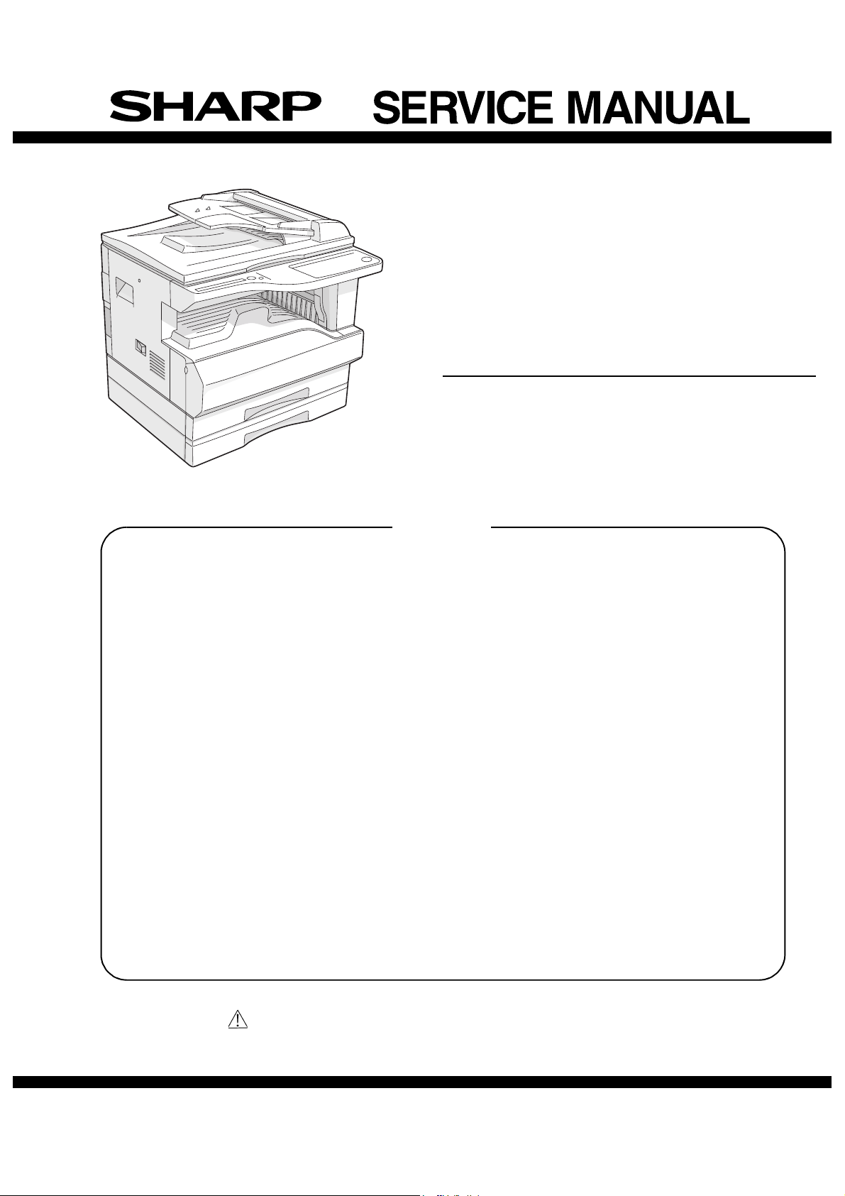
DIGITAL COPIER
MODEL AR-5320D
AR-5320D
(with option installed)
CONTENTS
[ 1 ] NOTE FOR THIS SERVICE MANUAL . . . . . . . . . . . . . . . Refer to AR-M160
[ 2 ] SPECIFICATIONS. . . . . . . . . . . . . . . . . . . . . . . . . . . . . . . . . . . . . AR-5320D
[ 3 ] CONSUMABLE PARTS. . . . . . . . . . . . . . . . . . . . . . . . . . . . . . . . . AR-5320D
[ 4 ] EXTERNAL VIEWS AND INTERNAL STRUCTURES . . . . . . . . . AR-5320D
[ 5 ] UNPACKING AND INSTALLATION . . . . . . . . . . . . . . . . . . . . . . . . AR-5320D
[ 6 ] ADJUSTMENTS . . . . . . . . . . . . . . . . . . . . . . . . . . . . . . . . Refer to AR-M160
[ 7 ] SIMULATIONS . . . . . . . . . . . . . . . . . . . . . . . . . . . . . . . . . . . . . . . AR-5320D
[ 8 ] USER PROGRAMS . . . . . . . . . . . . . . . . . . . . . . . . . . . . . . . . . . . AR-5320D
[ 9 ] TROUBLE CODE LIST . . . . . . . . . . . . . . . . . . . . . . . . . . . Refer to AR-M160
[10] MAINTENANCE . . . . . . . . . . . . . . . . . . . . . . . . . . . . . . . . . . . . . . AR-5320D
[11] DISASSEMBLY AND ASSEMBLY . . . . . . . . . . . . . . . . . . .Refer to AR-M160
[12] FLASH ROM VERSION UP PROCEDURE . . . . . . . . . . .Refer to AR-M160
[13] ELECTRICAL SECTION . . . . . . . . . . . . . . . . . . . . . . . . . . . . . . . . AR-5320D
Parts marked with ““ are important for maintaining the safety of the set.
Be sure to replace these parts with specified ones for maintaining the safety and performance of the set.
This document has been published to be used for
SHARP CORPORATION
after sales service only.
The contents are subject to change without notice.
Page 2
[1] NOTE FOR THIS SERVICE MANUAL
This Service Manual describes only the items related to the AR-5320D. For the other items common with the AR-M205, please refer to the AR-M160/
205 Service Manual (Document code:00ZARM205/A1E). The table below shows which document(s) should be referred to for each section. (Refer to
the document marked with O.)
[ 1 ] GENERAL O
[ 2 ] SPECIFICATIONS O
[ 3 ] CONSUMABLE PARTS O
[ 4 ] EXTERNAL VIEWS AND INTERNAL STRUCTURES O O Appearance / Internal / Operation panel
[ 5 ] UNPACKING AND INSTALLATION O O Changing the copy paper size in the tray
[ 6 ] ADJUSTMENTS O
[ 7 ] SIMULATIONS O O
[ 8 ] USER PROGRAMS O O
[ 9 ] TROUBLE CODE LIST O
[10] MAINTENANCE O
[11] DISASSEMBLY AND ASSEMBLY O
[12] FLASH ROM VERSION UP PROCEDURE O
[13] ELECTRICAL SECTION O O Block diagram / Actual wiring diagram 1/7
Section AR-M160/M205 AR-5320D Changed item
AR-5320D NOTE FOR THIS SERVICE MANUAL 1-1
Page 3
[2] SPECIFICATIONS
1. Copy mode
A. Type
Type Desk-top
Paper exit Wing less
B. Machine composition
AR-5320D 20-CPM multi function model
(1) Option
Machine Model
250 sheets paper feed unit AR-D24
250 sheets x 2 paper feed unit AR-D25
RSPF AR-RP6
Dual function board AR-EB7
256MB optional memory AR-SM5 option for AR-EB7
C. Copy speed
(1) Scan One Print many
AR-5320D Available
Condition: Copy speed in the normal copy from all the paper feed ports
including the manual paper feed port.
(2) Continuous copy speed (Sheets/min)
Paper size Normal
A3 11 11 11
B4 12 12 12
A4 20 20 20
AB
system
Inch
system
A4R 141414
B5 20 20 20
B5R 161616
11" X 17" 10 10 10
8.5" X 14" 12 12 12
8.5" X 13" 12 12 12
8.5" X 11" 20 20 20
8.5" X 11"R 15 15 15
8.5" X 5.5" 20 20 20
Enlargement
(200%)
D. First copy time
(1) Basic speed
First copy time 7.2sec (A4, 8.5" X 11"/1st tray/with OC)
(Polygon motor ready state)
E. Document
Max. document size A3, 11" X 17"
Document reference
position
Detection (Platen) None
Detection size A3, B4, A4, A4R, B5, B5R, A5
Left side center
11" X 17", 8.5" X 14", 8.5" X 13", 8.5" X 11",
8.5" X 11"R, 8.5" X 5.5"
(8.5" X 13" is detected by key input.)
Reduction
(50%)
(1) R-SPF
Standard/Option Option
AR-RP6
Document load
capacity
Document size
(Max. ~ Min.)
Document
replacement speed
Document set/Paper
feed direction
Document weight 56 ~ 90g/m·, 15 ~ 24 lbs
Document size
detection
Document mixture Copy mode: Not Available
40 sheets (Thickness 4mm or less)
A3 ~ A5
11" x 17" ~ 8.5" x 5.5"
(8.5" x 5.5", duplex is inhibited.)
20 sheets/min
(A4 , 8.5" x 11" normal copy)
Face up, Center reference,
Paper feed from the top
On the document feed tray
F. Paper feed
Copy size
(Max. ~ Min.)
Paper feed system 1 cassette + Multi manual paper feed
Paper feed capacity 250 x 2 (Paper feed tray)
Remaining quantity
detection
(1) Paper feed section of the copier
Paper feed
size
Side front Front
Paper feed
capacity
Detection Paper empty detection available, size detection
Weight 56 ~ 90g/m· (15 lbs. ~ 21 lbs.)
Special paper Recycled paper
(2) Manual paper feed section
Paper feed
size
Paper feed
capacity
Detection Size detection not available,
Weight 56 ~ 200g/m· (15 ~ 34 lbs.)
Special paper Recycled paper, OHP film, labels
Paper feed Single except for recycled paper
A3 ~ A6
11" x 17" ~ 8.5" x 5.5"
+ 100 (Multi bypass feed tray)
Cassette
section
Manual tray Only empty detection available
A3, B4, A4, A4R, B5, B5R, A5
11" x 17", 8.5" x 14", 8.5" x 13", 8.5" x 11",
8.5" x 11"R, 8.5" x 5.5"
(For A5 and 8.5" x 5.5", only No. 1 tray available.)
250 sheets
(56 ~ 90g/m· equivalent) (15 ~ 21 lbs.)
(by key input)
A3 ~ A6, 11" x 17" ~ 8.5" x 5.5"
100 sheets(56 ~ 80g/m·)
paper empty detection available
Only empty detection available
AR-5320D SPECIFICATIONS 2-1
Page 4
(3) Option paper feed unit
1-step paper feed unit 2-step paper feed unit
Model AR-D24 AR-D25
Paper feed size A3, B4, A4, A4R, B5, B5R
11" x 17", 8.5" x 14", 8.5" x 13",
8.5" x 11", 8.5" x 11"R
Capacity
(56 ~ 80gm·)
Paper weight 56 ~ 90 g/m· (15 ~ 21 lbs.)
Moisture preserving
heater
Paper empty detection Available
Paper size setting User setting
External dimensions
(W x D x H)
Weight About 4.7kg About 10kg
Special paper Recycled paper
Power Supplied from the machine
About 250 sheets x
1 tray
None
Paper size detection:None
590 x 471 x 88mm 590 x 471 x 173.5mm
About 250 sheets x
2 trays
G. Job speed
S-S (1st step) 100% (document replacement rate)
Condition:With SPF/RSPF A4/Letter Normal 1st tray
H. Multi copy
Max. number of multi copy 999 sheets
I. Warm-up time
Warm-up time 45 sec
Pre-heat Available
Jam recovery Within 45 sec
J. Copy magnification ratio
Fixed
magnification
ratio
Zooming 25 ~ 400%
Independent
zooming(vertical)
Independent zooming
(horizontal)
AB system:
50, 70, 81, 86, 100, 115, 122, 141, 200%
Inch system:
50, 64, 77, 95, 100, 121, 129, 141, 200%
SPF/RSPF(50 ~ 200%)
Available (25 ~ 400%)
SPF/RSPF(50 ~ 200%)
Available (25 ~ 400%)
SPF/RSPF(50 ~ 200%)
N. Paper exit / finishing
Paper exit section
capacity
Full detection None
Finishing Dual function board:
Electronic sort
capacity
Offset function Available (by the shifter)
Staple function None
(1) Electronic sort board (Option)
Electronic sort Sorting 100 sheets of A4 standard
Rotation copy If there is paper of same size as the document,
2 in 1, 4 in 1 Copies of 2 pages or 4 pages are integrated into
Edge erase Images surrounding the document are erased
Center erase The image at the center is erased when copying.
Margin shift Binding margin is made at the left edge of the set
Memory for
electronic sort
* Memory loading
capacity
Memory expansion DIMM memory slot x 1, max. 256MB x 1 slot +
USB2.0 Standard provision of E-sort
SPLC (JBIG-GDI) Supported when E-sort is installed.
ROPM Supported when E-sort is installed.
Face down 250 sheets
Option (AR-EB7)
A4 (8.5" x 11") standard document 100 sheets
documents
Grouping 100 sheets of A4 standard
documents
the image is rotated to copy even though the
paper is set in the different direction from the
document direction.
one surface. Divided by solid lines,
(Selectable by the user program.)
when copying. (Adjustable in 5 ~ 20mm by the
user program.)
(Adjustable in 5 ~ 20mm by the user program.)
documents.
(Adjustable in 5 ~ 20mm by the user program.)
16MB
A4 standard 100 pages
16MB (Max. 272MB in total)
K. Print density
Density mode Auto / Text / Photo
No. of manual
adjustment
Resolution Writing: 600 x 600dpi
Gradation Reading: 256 gradations
Toner save mode Set by the user program
5 steps (Text / Photo)
Reading: 600 (main) x 600 (sub) (PHOTO mode)
600 (main) x 300 (sub) (AE mode)
Writing: Binary
L. Void width
Void area Lead edge 1 ~ 4mm,
rear edge 4mm or less,
both sides 4mm or less
Image loss 4mm or less
M. Auto duplex
Standard/
Option
Standard provision
(D → D / D → S enable only when RSPF is installed)
AR-5320D SPECIFICATIONS 2-2
Page 5

O. Additional functions
APS O
AMS O
Auto tray switching O
Memory copy O
Rotation copy
E-sort O Option
Rotation sort X
Independent
zooming
1 set 2 copy O Enlargement invalid/SPF invalid
Binding margin Default AB series:
Edge erase Default AB series:
Center erase Default AB series:
Black/white
reverse
2in1/4in1
Sorter O Offset function (Shifter) provided
Preheating O The conditions are set by the user
Auto shut-off O The conditions are set by the user
User programming O
Total counter O Supports Total counter, Scan counter, and
Coin vendor
support
Auditor support O (Supports I/F only.)
Duplex O (Standard provision for the model of 20-
Toner save O (Set according to the destination)
Department
management
O
10mm (5, 10, 15, 20mm)
Inch series: 1/2 inch (1/4, 1/2, 3/4, 1 inch)
10mm (5, 10, 15, 20mm)
Inch series: 1/2 inch (1/4, 1/2, 3/4, 1 inch)
10mm (5, 10, 15, 20mm)
Inch series: 1/2 inch (1/4, 1/2, 3/4, 1 inch)
X
program.
program.
Copy counter.
O (Supports I/F only.)
sheet model only)
O (Copy: 20 Dept.)
S. Power source
Voltage AC120V, 220V, 230V, 240V ±15%
Frequency 50/60Hz common
T. Power consumption
Max. power consumption 1200W
* EnergyStar conformity
Average power consumption in
operation
Power consumption when
standby
Energy consumption efficiency Less than 25W
Less than 550W
5W(Not include option)
U. Digital performance
Resolution Reading 600 x 600dpi (PHOTO mode)
Writing 600 x 600dpi
Gradation Reading 256 gradations
Writing Binary
Memory Simplex:16MB Duplex:32MB
Hard disk None
600 x 300dpi (AE mode)
V. Printing function
Print speed <Standard>12ppm
Data resolution 600dpi
Option memory 16MB (with the AR-EB7 installed)
Printer driver Two drivers for the case when the AR-EB7 is
(With the AR-EB7 installed)
20ppm
256MB (AR-SM5) can be added to the AR-EB7.
installed and when it is not are automatically
installed by plug & play.
<Standard> SHARP GDI driver
<with the AR-EB7 installed> SPLC driver
O : Available :Installation of the option is required.
X : Not available
P. Other specifications
Photoconductor type OPC (Organic Photo Conductor)
Photoconductor drum dia. 30mm
Copy lamp Cold cathode fluorescent lamp (CCFL)
Developing system Dry 2-component magnetic brush
Charging system Saw teeth charging
Transfer system (+) DC corotron
Separation system (-) DC corotron
Fusing system Heat roller
Cleaning system Contact blade
development
Q. Package form
Body Body / Accessories
R. External view
External dimensions
(W x D x H)
Occupying area
(W x D)
Weight About 36.9kg (without DV-cartridge)
590 x 577 x 520 mm
590 x 531mm
(When the manual tray is installed.)
AR-5320D SPECIFICATIONS 2-3
Page 6
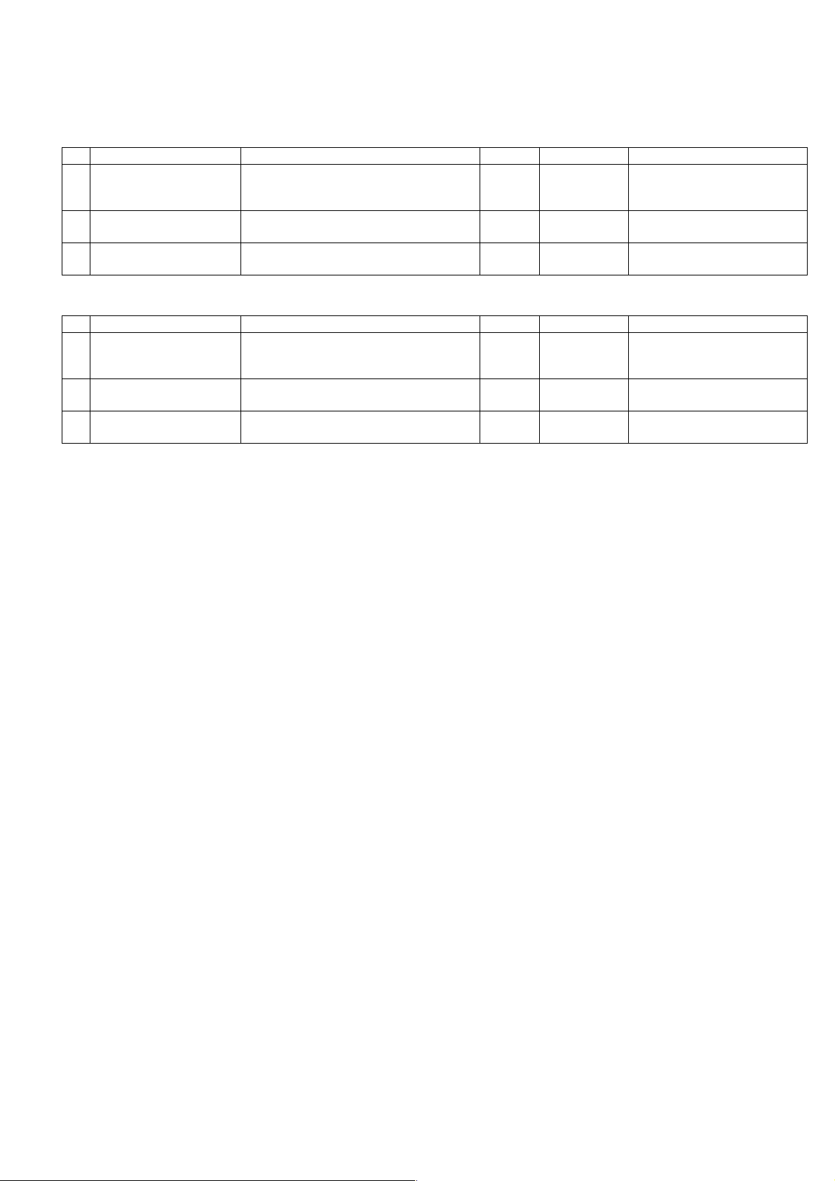
[3] CONSUMABLE PARTS
1. Supply system table
A. East Europe / Russia
NO Name Content Life Product name Remark
1 Toner cartridge(Black)
<With IC>
2 Developer Developer
3 Drum kit Drum
B. Latin America
NO Name Content Life Product name Remark
1 Toner cartridge(Black)
<With IC>
2 Developer Developer
3 Drum kit Drum
Toner
(Toner: Net Weight 537g)
Vinyl bag
(Developer : Net Weight 400g)
Drum fixing plate
Toner
(Toner: Net Weight 537g)
Vinyl bag
(Developer : Net Weight 400g)
Drum fixing plate
x10
160K AR-016LT Life setting by A4 6% document
x10
x10 500K AR-202LD LD=DV*10
x1x150K AR-202DM
x10
190K AR-016LT Life setting by A4 6% document
x10
x10 500K AR-202LD LD=DV*10
x1x150K AR-202DM
LT =T *1 0
LT =T *1 0
AR-5320D CONSUMABLE PARTS 3-1
Page 7
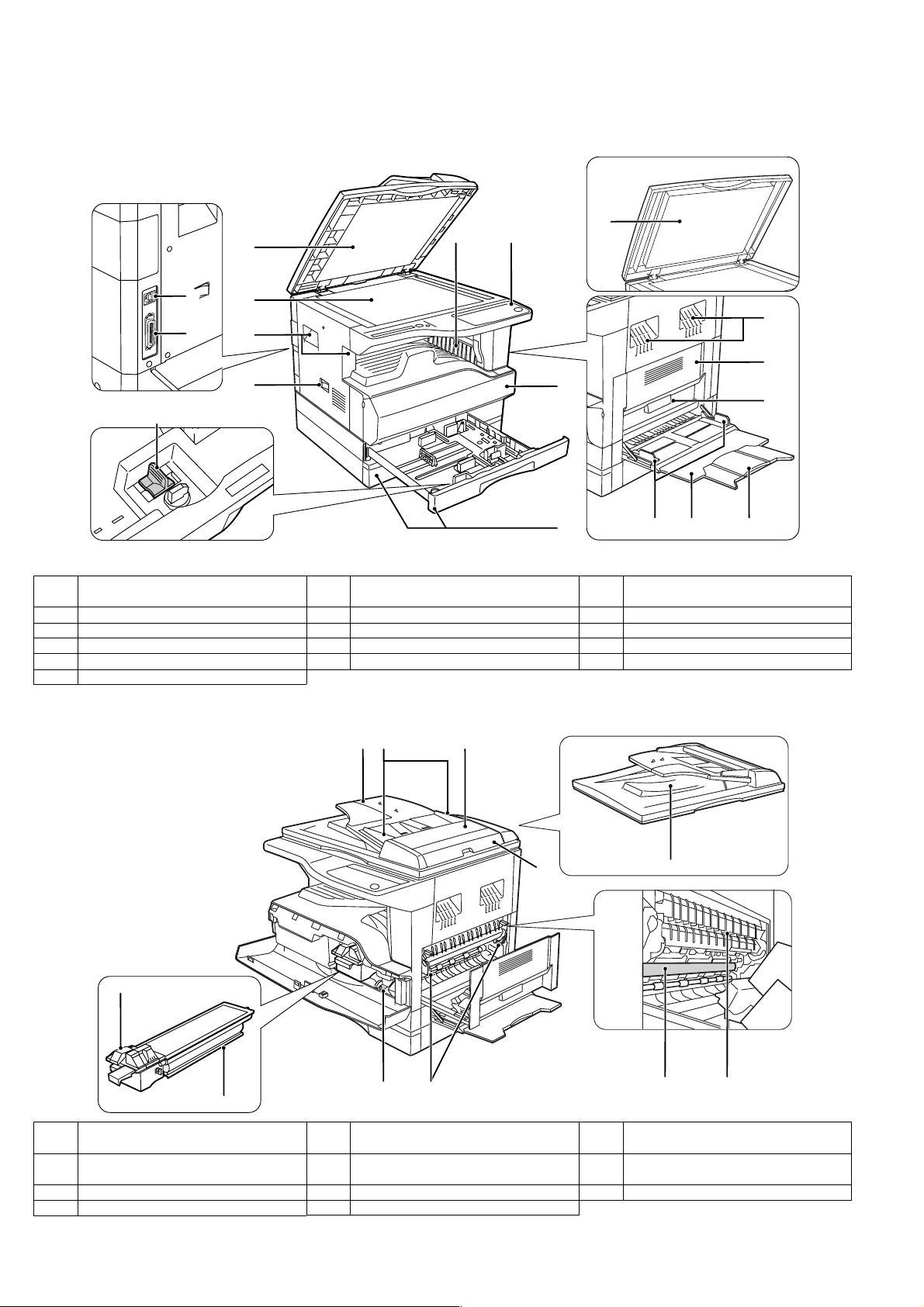
[4] EXTERNAL VIEWS AND INTERNAL STRUCTURES
1. Appearance
6 5
7
15
16
1
2
3
4
14
8
1
1 Document feeder cover (when the RSPF
is installed) /document cover
4 Power switch 5 Operation panel 6 Paper output tray
7 Front cover 8 Paper trays 9 Side cover
10 Side cover handle 11 Bypass tray guides 12 Bypass tray
13 Bypass tray extension 14 Charger cleaner 15 USB connector
16 Parallel connector
2 Document glass 3 Handles
3
9
10
131211
2. Internal
18
22
23
17 Document feeder tray
(when the RSPF is installed)
20 Right side cover
(when the RSPF is installed)
23 Toner cartridge 24 Roller rotating knob 25 Fusing unit release levers
26 Photoconductive drum 27 Fusing unit paper guide
18 Original guides
21 Exit area
24 25
(when the RSPF is installed)
(when the RSPF is installed)
1917
20
19 Feeding roller cover
22 Toner cartridge lock release lever
21
2726
(when the RSPF is installed)
AR-5320D EXTERNAL VIEWS AND INTERNAL STRUCTURES 4-1
Page 8
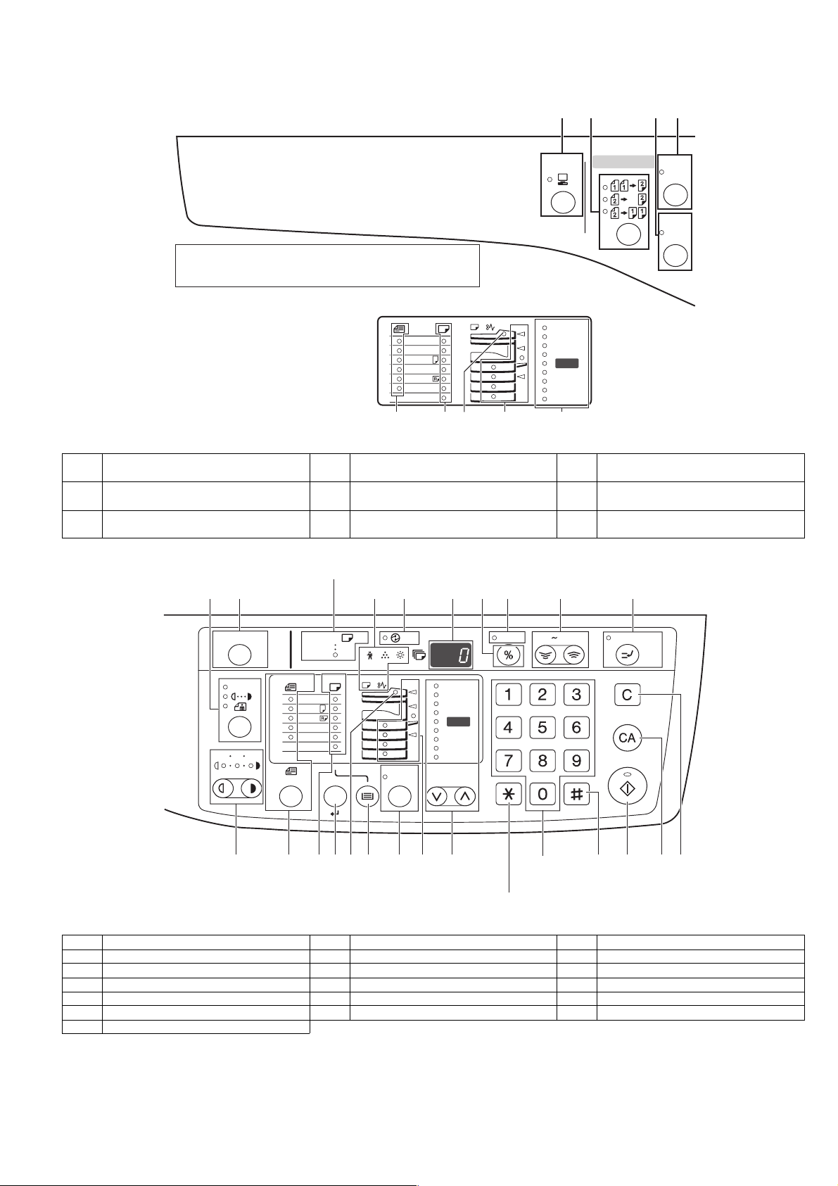
3. Operation Section
1 2 3 4
The indications of the operation panel may differ
depending on the country and the region.
The example of a display of inch series
11X17
X
14
8½
X
11
8½
X
5½
8½
X
11
8½
8½X13
EXTRA
7
8
1 ON LINE key/indicator 2 ORIGINAL TO COPY key/indicators
(Duplex model only)
4 XY-ZOOM key/indicator 5 RSPF indicator
(when the RSPF is installed)
7 ORIGINAL SIZE ENTER key /
8 PAPER SIZE indicators 9 PRESET RATIO selector keys /
ORIGINAL SIZE indicators
6
5
ON LINE
200
141
129
121
100
95
77
64
%
%
50
%
ORIGINAL TO COPY
XYZOOM
DUAL
PA G E
COPY
9
3 DUAL PAGE COPY key/indicator
6 Paper feed location / misfeed location
indicators
indicators
12
10
ACC.#-C
135
11
AU TO
20
EXTRA
ENTER
7
A3
A4
A4
A5
B4
AU TO
8
21
13
14
AU TO
%
5
22
23
6
15
200
141
122
115
100
9
16
17
ZOOM
%
%
86
81
70
50
%
18
25 400%
INTERRUPT
24 26
19
28
2725
Not used for this machine.
10 AUTO/TEXT/PHOTO key / indicators 11 AUDIT CLEAR key 12 AUTO PAPER SELECT indicator
13 Alarm indicators 14 POWER SAVE indicator 15 Display
16 Copy ratio display key 17 ZOOM indicator 18 Zoom keys
19 INTERRUPT key / indicator 20 Light and Dark keys / indicators 21 PAPER SIZE ENTER key
22 TRAY SELECT key 23 AUTO IMAGE key / indicator 24 Numeric keys
25 # key 26 START key / indicator 27 CLEAR ALL key
28 CLEAR key
AR-5320D EXTERNAL VIEWS AND INTERNAL STRUCTURES 4-2
Page 9
[5]UNPACKING AND INSTALLATION
A3
A4
A4
A5
B4
TRA
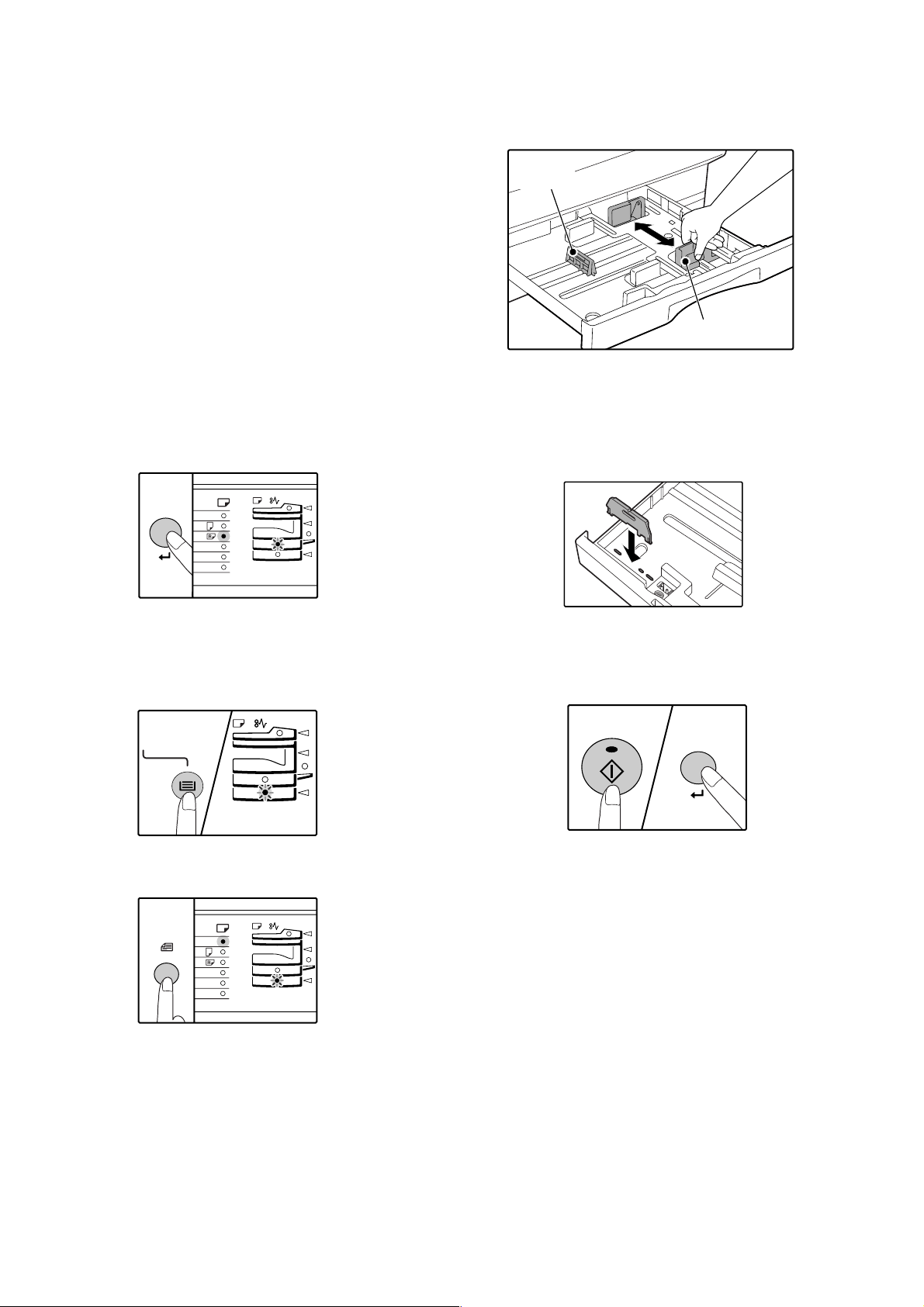
5. Changing a tray's paper size setting
Follow these steps to change a tray's paper size setting.
Note:
•The paper size setting cannot be changed when the machine has
stopped temporarily due to running out of paper or a misfeed, or during
interrupt copying.
•During printing (even in copy mode), the paper size setting cannot be
changed.
•A5 size paper can only be selected in upper paper tray.
•Do not load paper that is a different size than the paper size setting.
Copying will not be possible.
4) Squeeze the lock lever of the front guide and slide the front guide to
match the width of the paper, and move the left guide to the
appropriate slot as marked on the tray.
Left guide
Front guide
1) Hold down the [PAPER SIZE ENTER] key for more than 5 seconds
to set the selected paper size.
The currently selected paper feed location indicator will blink and the
corresponding paper size (which is currently set) indicator will light
steadily.
All other indicators will go out.
2) If the machine has two paper trays, use the [TRAY SELECT] key to
select the paper tray for which you wish to change the paper size
setting.
Each time the [TRAY SELECT] key is pressed, a paper tray will be
indicated with a blinking paper feed location indicator.
•The front guide is a slide-type guide. Grasp the locking knob on the
guide and slide the guide to the indicator line of the paper to be loaded.
•The left guide is an insert-type guide. Remove it and then insert it at the
indicator line of the paper to be loaded.
•When using 11" x 17" sized paper store the left guide in the slot at the
left front of the paper tray.
5) Press the [START] key and then the [PAPER SIZE ENTER] key.
To change the paper size setting of another tray, repeat steps 2) to 5)
after pressing the [START] key.
3) Use the [ORIGINAL SIZE ENTER] key to select the paper size.
The indicator of the selected paper size lights up.
ENTER
AR-5320D UNPACKING AND INSTALLATION 5-1
Note:Affix the paper size label for the paper size selected in step 3) to
the label position on the right end of the tray.
Important points when using the printer mode
•Make sure that the tray's paper size setting is the same as the tray's
paper size setting in the printer driver. For example, if the tray's paper
size setting is A4R, set "Setting Paper Size" to "A4-R". For more
information, see "CONFIGURING THE PRINTER DRIVER" in the
"Software Setup Guide".
Page 10
[7] SIMULATIONS
1. Entering the simulation mode
Perform the following procedure to enter the simulation mode.
"#" key Interrupt key "C" key Interrupt key
Main code Start key Sub code Start key
2. Canceling the simulation mode
When the clear all key is pressed, the simulation mode is cancelled.
When the interruption key is pressed, the process is interrupted and the
screen returns to the sub code entering display.
* After canceling the simulation mode, be sure to turn OFF/ON the
power and check the operation.
Note: If the machine is terminated by a jam error or paper empty during
copying in the adjustment by the simulation, recopying is required.
3. List of simulations
Main
Sub
code
code
01 01 Mirror scanning operation
02 Mirror home position sensor (MHPS) status display
06 Mirror scanning operation aging
02 01 Single paper feeder (SPF) aging
02 SPF sensor status display
03 SPF motor operation check
08 SPF paper feed solenoid operation check
09 RSPF reverse solenoid operation check
10 RSPF paper exit gate solenoid operation check
11 SPF PS release solenoid operation check
03 02 Shifter sensors status display
03 Shifter operation check
11 Shifter home position check
05 01 Operation panel display check
02 Fusing lamp and cooling fan operation check
03 Copy lamp lighting check
06 01 Paper feed solenoid operation check
02 Resist roller solenoid operation check
10 Main cassette semicircular roller cleaning
07 01 Warm-up display and aging with jam
06 Intermittent aging
08 Shifting with warm-up display
08 01 Developing bias output
02 Main charger output (Grid = HIGH)
03 Main charger output (Grid = LOW)
06 Transfer charger output
09 01 Duplex motor forward rotation check
02 Duplex motor reverse rotation check
04 Duplex motor RPM adjustment
05 Duplex motor switchback time adjustment
10 - Toner motor operation
14 - Trouble cancel (except for U2)
16 - U2 trouble cancel
20 01 Maintenance counter clear
21 01 Maintenance cycle setting
22 01 Maintenance counter display
02 Maintenance preset display
03 Jam memory display
04 Jam total counter display
05 Total counter display
06 Developing counter display
08 SPF counter display
09 Paper feed counter display
12 Drum counter display
13 CRUM type display
14 P-ROM version display
15 Trouble memory display
16 Duplex print counter display
17 Copy counter display
18 Printer counter display
19 Scanner mode counter display
<Not Available for AR-5320D>
21 Scanner counter display <Not Available for AR-5320D>
22 SPF jam counter display
Contents
AR-5320D SIMULATIONS 7-1
Page 11
Main
code
Sub
code
Contents
24 01 Jam total counter clear
02 Trouble memory clear
04 SPF counter clear
05 Duplex print counter clear
06 Paper feed counter clear
07 Drum counter clear
08 Copy counter clear
09 Printer counter clear
13 Scanner counter clear <Not Available for AR-5320D>
14 SPF jam total counter clear
15 Scanner mode counter clear
<Not Available for AR-5320D>
25 01 Main motor operation check
10 Polygon motor operation check
26 02 Size setting
03 Auditor setting
04 Copier duplex setting
05 Count mode setting
06 Destination setting
07 Machine condition check (CPM)
18 Toner save mode setting
30 CE mark conformity control ON/OFF
31 Auditor mode exclusive setup
36 Cancel of stop at maintenance life over
37 Cancel of stop at developer life over
38 Cancel of stop at drum life over
39 Memory capacity check
42 Transfer ON/OFF timing control setting
43 Side void amount setting
51 Copy temporary stop function setting
30 01 Paper sensor status display
42 01 Developing counter clear
43 01 Fusing temperature setting
10 Postcard paper feed cycle setting
<Not Available for AR-5320D>
11 Postcard size paper fusing temperature setting
<Not Available for AR-5320D>
12 Standby mode fusing fan rotation setting
13 Fusing paper interval control allow/inhibit setting
44 34 Transfer current setting
40 Setting of rotation time before toner supply
46 01 Copy density adjustment (300dpi)
02 Copy density adjustment (600dpi)
09 Copy exposure level adjustment, individual setting
(Text) 300dpi
10 Copy exposure level adjustment, individual setting
(Text) 600dpi
11 Copy exposure level adjustment, individual setting
(Photo) 600dpi
18 Image contrast adjustment (300dpi)
19 Exposure mode setting
(Gamma table setting/AE operation mode setting/
Photo image process setting)
20 SPF exposure correction
29 Image contrast adjustment (600dpi)
30 AE limit setting
31 Image sharpness adjustment
48 01 Main/sub scanning magnification ratio adjustment
05 SPF/RSPF mode sub scanning magnification ratio
adjustment in copying
Main
code
Sub
code
Contents
49 01 Flash ROM program writing mode
12 Standby mode fusing fan RPM setting<Additional>
50 01 Image lead edge adjustment
06 Copy lead edge position adjustment (SPF/RSPF)
10 Paper off-center adjustment
12 Document off-center adjustment
18 Memory reverse position adjustment in duplex copy
19 Rear edge void adjustment in duplex copy
51 02 Resist amount adjustment
53 08 SPF scanning position automatic adjustment
10 SPF scan position change-over setting
61 03 HSYNC output check
63 01 Shading check
07 SPF automatic correction
64 01 Self print
AR-5320D SIMULATIONS 7-2
Page 12
4. Contents of simulations
Main
Sub
code
code
01 01 Mirror scanning operation When the [START] key is pressed, the home position is checked in the first place, and the mirror
02 Mirror home position sensor
(MHPS) status display
06 Mirror scanning operation aging When the [START] key is pressed, the mirror base performs A3 full scanning at the set magnification
02 01 Single paper feeder (SPF) aging When the [START] key is pressed, the set magnification ratio is acquired and document transport
02 SPF sensor status display (In order to receive the sensor change notification, the load must be decreased.)
Contents Details of operation
base performs A3 full scanning once at the set magnification ratio speed. During this scanning, the
set magnification ratio is displayed. The mirror home position sensor status is displayed with the DV
replacement/OPC drum cartridge replacement lamp.
(The lamp lights up when the mirror is in the home position.)
During scanning, the copy lamp lights up.
When the [Interrupt] key is pressed, the operation is interrupted to go to the sub code input standby
mode.
Used to monitor the mirror home position sensor. When the sensor is ON, the DV replacement/OPC
drum cartridge replacement lamp is lighted. During that time, the display section displays the sub
code. When the [Interrupt] key is pressed, the machine goes to the sub code input standby mode.
(When the CA key is pressed, the simulation is terminated.)
ratio speed. During scanning, the set magnification ratio is displayed. After 3 seconds, the mirror
base performs full scanning again. During scanning, the set magnification ratio is displayed.
* When the [START] key is pressed again, the ready lamp turns and remains off.
The DV replacement/OPC drum cartridge replacement lamp displays the status of the mirror
home position sensor. (The lamp lights up when the mirror is in the home position.)
During aging, the copy lamp lights up. When the [Interrupt] key is pressed, the operation is
interrupted if operating, and the machine goes into the sub code input standby mode.
operation of single surface is performed in the case of SPF or document transport operation of
duplex surfaces is performed in the case of RSPF. Since, however, there is no limited condition for
this operation, it does not stop even at a paper jam. During operation, the LED on the display section
corresponding to the selected magnification ratio lights up, and the magnification ratio is displayed
on the 7-seg display. When the [Interrupt] key is pressed at that time, the machine goes to the sub
code input standby mode. When the [CA] key is pressed, the simulation is terminated.
The sensor status (ON/OFF) in the SPF can be checked with the following lamps.
When a sensor detects paper, it turns on. The open/close detection sensor turns on when the
machine is opened.
Display lamp Sensor
Toner supply lamp
Copier jam lamp
The DV replacement/OPC drum cartridge lamp
Paper empty lamp
SPF jam lamp
Manual paper feed lamp
Tray jam lamp
AE lamp
TEXT lamp
PHOTO lamp
SPF document set sensor
SPF document transport sensor
SPF unit (OC cover) open/close sensor
SPF paper exit sensor
SPF paper feed cover open/close sensor
SPF paper length sensor 1
SPF paper length sensor 2
SPF paper feed width sensor (small)
SPF paper feed width sensor (middle)
SPF paper feed width sensor (large)
When the [Interrupt] key is pressed, the machine goes to the sub code input standby mode.
When the [CA] key is pressed, the simulation is terminated.
03 SPF motor operation check When the [START] key is pressed, the motor rotates for 10 sec at the speed corresponding to the set
08 SPF paper feed solenoid operation
check
09 RSPF reverse solenoid operation
check
10 RSPF paper exit gate solenoid
operation check
magnification ratio. When the [Interrupt] key is pressed, the machine stops operation and goes to the
sub code input standby mode. When the [CA] key is pressed, the simulation is terminated.
The SPF paper feed solenoid (PSOL) is turned ON for 500msec and OFF for 500msec.
This operation is repeated 20 times.
After completion of the process, the machine goes to the sub code input standby mode.
When the [Interrupt] key is pressed during the process, the machine goes to the sub code input
standby mode. When the [CA] key is pressed, the simulation is terminated.
The RSPF reverse solenoid (PSOL) is turned ON for 500msec and OFF for 500msec.
This operation is repeated 20 times.
After completion of the process, the machine goes to the sub code input standby mode.
When the [Interrupt] key is pressed during the process, the machine goes to the sub code input
standby mode. When the [CA] key is pressed, the simulation is terminated.
The RSPF paper exit gate solenoid (GSOL) is turned ON for 500msec and OFF for 500msec.
This operation is repeated 20 times.
After completion of the process, the machine goes to the sub code input standby mode.
When the [Interrupt] key is pressed during the process, the machine goes to the sub code input
standby mode. When the [CA] key is pressed, the simulation is terminated.
AR-5320D SIMULATIONS 7-3
Page 13

Main
Sub
code
code
02 11 SPF PS release solenoid operation
check
Contents Details of operation
The SPF PS release solenoid (CLH) is turned ON for 500msec and OFF for 500msec. This operation
is repeated 20 times.
After completion of the process, the machine goes to the sub code input standby mode. When the
[Interrupt] key is pressed during the process, the machine goes to the sub code input standby mode.
When the [CA] key is pressed, the simulation is terminated.
03 02 Shifter sensors status display The shifter HP sensor is monitored. When the sensor is ON, the [Copier position jam lamp] is lighted.
During this operation, the display section displays the sub code. When the [Interrupt] key is pressed,
the machine goes to the sub code input standby mode. When the [CA] key is pressed, the simulation
is terminated.
03 Shifter operation check The shifter is reciprocated 4 times. During the process, the display section displays the sub code.
After completion of the process, the machine goes to the sub code input standby mode. When the
[Interrupt] key is pressed during the process, the machine goes to the sub code input standby mode.
When the [CA] key is pressed, the simulation is terminated. To stop the shifter, however, stop is in
the home position.
11 Shifter home position check The shifter is moved in one direction by the specified steps. The 7-seg LED displays the sub code.
While the shifter is moving, the shifter HP sensor is monitored. While the sensor is ON, the machine
position jam lamp is lighted.
3 key:
4 key:
5 key:
Step toward the front
Step toward the rear
Initial
When the [Interrupt] key is pressed during the process, the machine goes to the sub code input
standby mode. When the [CA] key is pressed, the simulation is terminated.
05 01 Operation panel display check <<LED check mode (ALL ON/Individual ON)>>
When the [START] key is pressed in the sub code input mode, all the LED's (including the 7-seg
lamps) are turned ON. After 5 sec of all ON, the machine goes to the sub code input standby mode.
When the [Mode select] key is pressed during all ON, the lighting mode is shifted to the individual ON
mode, where the LED's are individually lighted from the left top, to the left bottom, to the next line top,
to the bottom, and so on. (For the 7-seg lamps, the 3-digit lamps are lighted at once.)
After completion of lighting of all the lamps, the mode is shifted to the all ON mode.
After 5 sec of all ON mode, the machine goes to the sub code input standby mode.
Individual ON mode cycle: 300ms for ON 20ms for OFF
When the [Interrupt] key is pressed in the LCD check mode, the machine goes back to the sub code
input standby mode.
When the [CA] key is pressed, the simulation is terminated.
When the [START] key is pressed with all the lamps ON, the machine goes back to the key input
check mode.
<< Key input check mode>>
When the machine goes into the key input check mode, [- - -] is displayed on the copy quantity
display. Every time when a key on the operation panel is pressed, the input value is added on the
copy quantity display.
[- - -] [ 1] [ 2] •••.
When a key is pressed once, it is not counted again.
When the [START] key is pressed, the input number is added and displayed for 3 sec, and the
machine goes into the LED lighting check mode (LED all ON state). When the [Interrupt] key is
pressed for the first time, it is counted. When the key is pressed for the second time, the machine
goes into the sub code input mode. When the [CA] key is pressed for the first time, it is counted.
When the key is pressed for the second time, the simulation is terminated. (Note for the key input
check mode).
•Press the [START] key at the end. (When the key is pressed during the process, the machine goes
into the LED lighting check mode (all ON state).).
•When two or more keys are pressed simultaneously, they are ignored.
02 Fusing lamp and cooling fan
operation check
When the [START] key is pressed, the fusing lamp turns ON for 500ms and OFF for 500ms.
The operation is repeated 5 times. During this process, the cooling fan motor rotates.
After completion of the process, the machine goes into the sub code input standby mode.
03 Copy lamp lighting check When the [START] key is pressed, the copy lamp lights up for 5 sec. After completion of lighting, the
machine goes into the sub code input mode.
When the [Interrupt] key is pressed, the process is interrupted and the machine goes into the sub
code input standby mode. When the [CA] key is pressed, the simulation is terminated.
AR-5320D SIMULATIONS 7-4
Page 14

Main
Sub
code
code
06 01 Paper feed solenoid operation
check
Contents Details of operation
When this simulation is executed, the sub code is displayed on the 7-seg LED and the lamp
corresponding to the solenoid lights up.
Select a solenoid with the tray select key (the lamp corresponding to the solenoid lights up) and
press the [START] key, and the machine repeats operation of ON for 500ms and OFF for 500ms.
This operation is repeated 20 times.
After that, the machine goes into the sub code entry standby mode.
Display lamp Solenoid
Main cassette lamp
2nd cassette lamp
3rd cassette lamp
4th cassette lamp
Manual paper feed lamp
2nd cassette jam lamp
Machine jam lamp & 2nd cassette jam lamp
Main cassette paper feed solenoid
* 2nd cassette paper feed solenoid
* 3rd cassette paper feed solenoid
* 4th cassette paper feed solenoid
Manual paper feed solenoid
* 2nd cassette paper transport solenoid
* 3rd cassette transport solenoid
* Supported for the installed models only. Skipped for the models without installation.
02 Resist roller solenoid operation
check
When the [START] key is pressed in the sub code input state, the resist solenoid (RRS) turns ON for
500ms and OFF for 500ms. This operation is repeated 20 times.
After completion of the process, the machine goes into the sub code input standby mode.
When [INTERRUPT] key is pressed during the process, the machine goes into the sub code input
standby mode. When [CA] key is pressed, the simulation is terminated.
10 Cassette semi-circular roller
cleaning
First of all, remove the developer unit.
Enter the simulation code, specify the cassette to be cleaned with the tray select key, and press
START button. The main motor rotates to move the cassette semi-circular roller by half circle and
make the roller face downward.
After completion of cleaning, when INTERRUPT key is pressed, the machine goes into the sub code
entry standby mode and the roller returns to the original positions.
To clean another roller continuously, press INTERRUPT key to return the roller to the original
position, and execute the simulation again.
During the operation, the sub code is displayed on the display.
* When CA key is pressed, the simulation mode is terminated.
However, the roller returns to the original position by the initial operation.
07 01 Warm-up display and aging with
jam
Copying is repeated to make the set copy quantity. When this simulation is executed, warm-up is
started and warm-up time is counted up every second from 0 and displayed. After completion of
warm-up, warm-up time count is stopped. When the [CA] key is pressed, the ready lamp lights up.
After that, when the copy quantity is inputted with keys and the [START] key is pressed, copying is
repeated to make the set copy quantity. (Intermittent 0 sec)This simulation is canceled by turning off
the power or performing a simulation that executes hardware reset.
06 Intermittent aging Copying is repeated to make the set copy quantity. When this simulation is performed, warm-up is
performed and the ready lamp is lighted. Enter the copy quantity with the key and press the [START]
key, and copying is repeated to make the set copy quantity, the ready state remains for 3 sec, and
copying is repeated again to make the set copy quantity. These operations are repeated.
This simulation is canceled by turning off the power or performing a simulation that executes
hardware reset.
08 Shifting with warm-up display
(Shifting similar to pressing the CA
key)
When the simulation code is entered, warm-up is started and warm-up time is counted up every
second from 0 and displayed. When the [CA] key is pressed during counting up, the display section
displays "0" and count-up process stops. However, warm-up is continued.
After completion of warm-up, counting is stopped. Press the [CA] key to terminate the simulation
mode. (This simulation is similar to SIM07-01, but without the aging function.)
AR-5320D SIMULATIONS 7-5
Page 15

Main
code
Sub
code
Contents Details of operation
08 01 Developing bias output When the [START] key is pressed, the developing bias signal is turned ON for 30 sec.
However, to calculate the actual output value is calculated, execute SIM25-01.
After completion of the process, the machine goes into the sub code input standby mode.
When [INTERRUPT] key is pressed during the process, the machine goes into the sub code input
standby mode. When [CA] key is pressed, the simulation is terminated.
02 Main charger output (Grid = HIGH) When the [START] key is pressed, the main charger output is supplied for 30 sec in the grid voltage
HIGH mode. After completion of the process, the machine goes into the sub code input standby
mode.
When [INTERRUPT] key is pressed during the process, the machine goes into the sub code input
standby mode. When [CA] key is pressed, the simulation is terminated.
03 Main charger output (Grid = LOW) When the [START] key is pressed, the main charger output is supplied for 30 sec in the grid voltage
LOW mode. After completion of the process, the machine goes into the sub code input standby
mode.
When [INTERRUPT] key is pressed during the process, the machine goes into the sub code input
standby mode. When [CA] key is pressed, the simulation is terminated.
06 Transfer charger output Select an output mode with the [Mode select] key and press the [START] key. The transfer charger
output is delivered for 30 sec in the selected mode.
After 30 sec of transfer charger output, the machine goes into the sub code entry standby mode.
When [INTERRUPT] key is pressed during the process, the machine goes into the sub code input
standby mode. When [CA] key is pressed, the simulation is terminated.
Display lamp Output mode
AE mode lamp
TEXT mode lamp
AE mode lamp & PHOTO mode lamp
TEXT mode lamp & PHOTO mode lamp
AE & TEXT & PHOTO mode lamp
Normal size width: Front surface
Normal size width: Back surface
Small size width: Front surface
Small size width: Back surface
Manual paper feed mode
•Small size is Letter R (A4R) or smaller.
09 01 Duplex motor forward rotation
check
The duplex motor is driven in forward direction (in the paper exit direction) for 30 sec.
During the process, the display section displays the sub code.
After completion of the process, the machine goes into the sub code input standby mode.
When the [Interrupt] key is pressed, the machine goes into the sub code input standby mode.
When the [CA] key is pressed, the simulation is terminated.
02 Duplex motor reverse rotation
check
The duplex motor is driven in reverse direction for 30 sec.
During the process, the display section displays the sub code.
After completion of the process, the machine goes into the sub code input standby mode.
When the [Interrupt] key is pressed, the machine goes into the sub code input standby mode.
When the [CA] key is pressed, the simulation is terminated.
04 Duplex motor RPM adjustment When any key input is made, it is displayed on the display section.
When the [START] key is pressed, the set code data are acquired and stored in the EEPROM, and
the machine goes into the sub code input standby mode.
When, however, the [START] key is pressed outside the set range, it is not assured.
Set range: 1 - 13 Default: 4
At that time, when the [Interrupt] key is pressed, the data are not rewritten and the machine goes into
the sub code input standby mode.
When the [CA] key is pressed, the simulation is terminated without rewriting the data.
05 Duplex motor switchback time
adjustment
When any key input is made, it is displayed on the display section. When the [START] key is pressed,
the set code data are acquired and stored in the EEPROM, and the machine goes into the sub code
input standby mode.
Set range: 50 ~ 76 Default: 50
(Change quantity 1 1-2 phase 3 steps)
At that time, when the [Interrupt] key is pressed, the data are not rewritten and the machine goes into
the sub code input standby mode.
When the [CA] key is pressed, the simulation is terminated without rewriting the data.
10 - Toner motor operation When the [START] key is pressed, the toner motor is driven for 30 sec.
After completion of the process, the machine goes into the main code input standby mode.
When the [Interrupt] key is pressed, the machine goes into the main code input standby mode.
* If this simulation is executed with the toner cartridge installed, an over toner error may occur.
14 - Trouble cancel (except for U2) * Trouble to write into the EEPROM such as H trouble is canceled and hardware reset is
performed.
16 - U2 trouble cancel * U2 trouble is canceled and hardware reset is performed.
20 01 Maintenance counter clear When the [Start] key is pressed, the maintenance count value is cleared and "000000" is displayed.
(Alternate display of "000" and "000")
AR-5320D SIMULATIONS 7-6
Page 16

Main
code
Sub
code
Contents Details of operation
21 01 Maintenance cycle setting The current set maintenance cycle code is displayed (initial display), and the set data are stored.
Code Setting
0
1
2
3
4
5
5,000 sheets
7,500 sheets
10,000 sheets
25,000 sheets
50,000 sheets * Default
Free (999,999 sheets)
22 01 Maintenance counter display The maintenance counter value is displayed. (Alternate display by 3 digits)
02 Maintenance preset display (Valid
only when the destination is set to
The copy quantity corresponding to the code that is set with SIM21-01 is displayed.
(For example: 50,000 sheets)
EX Japan)
03 Jam memory display The LED of the latest jam position is lighted. Every time when the magnification ratio display key is
pressed, the jam memory data is acquired sequentially from the latest. The jam position is judged by
the acquired data and the corresponding LED is lighted. The 7-seg display indicates the jam number.
At that time, "A" is displayed on the upper first digit. When the last one is displayed, the latest one will
be displayed again. Max. 30 jams from the latest are stored. When the [Interrupt] key is pressed, the
machine goes into the sub code input standby mode. When the [CA] key is pressed, the simulation is
terminated.
04 Jam total counter display The jam total counter value is displayed. (Alternate display by 3 digits)
05 Total counter display The total counter value is displayed. (Alternate display by 3 digits)
06 Developing counter display The developing counter data is acquired and displayed on the 7-seg display. (Alternate display by 3
digits)
When the [Interrupt] key is pressed, the machine goes into the sub code input standby mode.
When the [CA] key is pressed, the simulation is terminated.
08 SPF counter display The SPF counter value is displayed. (Alternate display by 3 digits)
09 Paper feed counter display The counter value of the selected paper feed section is acquired from each variable, the data is
displayed on the 7-seg display according to the regulations. When this simulation is executed, the
value of the first cassette is displayed first. Press the tray select key to select the paper feed tray.
When the [Interrupt] key is pressed, the machine goes into the sub code input standby mode.
When the [CA] key is pressed, the simulation is terminated.
12 Drum counter display The drum counter and the drum rotating time are displayed.
To change the display mode, press the [Mode select] key.
Display lamp
AE mode lamp
TEXT mode lamp
Display mode
Drum counter
Drum rotating time
13 CRUM destination display When this simulation is executed, the CRUM destination set (written) in the CRUM chip is displayed.
This simulation is valid only for the models where the CRUM is valid.
7-seg display Meaning (CRUM destination) 7-seg display Meaning (CRUM destination)
00
01
02
03
Not set yet
BTA-A
BTA-B
BTA-C
04
99
12
BTA-E
Conversion
AL series
14 P-ROM version display The P-ROM version is displayed on the copy quantity display. The main code and the sub code are
alternatively displayed by 2 digits. The display interval is same as that of the counter display.
By pressing the fixed magnification ratio key, each version display is switched.
Display lamp (AB series) Display lamp (Inch series) Displayed version
141% 141% Machine program
15 Trouble memory display The trouble codes up to the latest one are acquired from the trouble memory data.
Every time when the magnification ratio display is pressed, the main code of the trouble is displayed
on the 1st ~ 2nd digit.
* The latest 20 troubles are stored in the memory.
The 3rd digit indicates the trouble history code, "A" ~ "J" (meaning of 1 ~ 10).
After "J" is displayed, "A" ~ "J" blinks. (Meaning of 11 ~ 20)
After "J" blinks (meaning of 20), "A" ~ "J" is lighted. (Returns to 1.)
When the [START] key is pressed, the sub code is displayed.
When the [Interrupt] key is pressed, the machine goes into the sub code input standby mode.
When the [CA] key is pressed, the simulation is terminated.
* Note that when the history code blinks, the trouble code and the sub code do not blink.
16 Duplex print counter display Data is acquired from the duplex print counter variable, and is displayed.
When the [Interrupt] key is pressed, the machine goes into the sub code input standby mode.
When the [CA] key is pressed, the simulation is terminated.
AR-5320D SIMULATIONS 7-7
Page 17

Main
code
Sub
code
Contents Details of operation
22 17 Copy counter display The copy counter value is displayed. (Alternate display by 3 digits) When the [Interrupt] key is
pressed, the machine goes into the sub code input standby mode. When the [CA] key is pressed, the
simulation is terminated.
18 Printer counter display The printer counter value is displayed. (Alternate display by 3 digits)When the [Interrupt] key is
pressed, the machine goes into the sub code input standby mode. When the [CA] key is pressed, the
simulation is terminated.
19 Scanner mode counter display
<Not Available for AR-5320D>
21 Scanner counter display
<Not Available for AR-5320D>
The scanner mode counter value is displayed. When the [Interrupt] key is pressed, the machine goes
into the sub code input standby mode. When the [CA] key is pressed, the simulation is terminated.
The scanner counter value is displayed. (Alternate display by 3 digits)When the [Interrupt] key is
pressed, the machine goes into the sub code input standby mode. When the [CA] key is pressed, the
simulation is terminated.
22 SPF jam counter display The SPF jam counter value is displayed. (Alternate display by 3 digits)When the [Interrupt] key is
pressed, the machine goes into the sub code input standby mode. When the [CA] key is pressed, the
simulation is terminated.
24 01 Jam total counter clear When the [START] key is pressed, the jam total count value is reset to zero, and zero is displayed.
02 Trouble memory clear The trouble memory and the EEPROM trouble history data are cleared and "000" is displayed on the
7-seg display. When the [Interrupt] key is pressed, the machine goes into the sub code input standby
mode. When the [CA] key is pressed, the simulation is terminated.
04 SPF counter clear When the [START] key is pressed, the SPF count value is reset to zero and displayed on the 7-seg
display. When the [Interrupt] key is pressed, the machine goes into the sub code input standby mode.
When the [CA] key is pressed, the simulation is terminated.
05 Duplex print counter clear The duplex print count data is cleared, and zero is displayed on the 7-seg display.
When the [Interrupt] key is pressed, the machine goes into the sub code input standby mode.
When the [CA] key is pressed, the simulation is terminated.
06 Paper feed counter clear The paper feed counter data of each paper feed section is cleared, and "000" is displayed on the 7-
seg display. When the [Interrupt] key is pressed, the machine goes into the sub code input standby
mode. When the [CA] key is pressed, the simulation is terminated.
07 Drum counter clear When the [START] key is pressed, the drum count and the drum roasting time are reset to zero, and
the drum counter value is displayed on the 7-seg LED. When the [Interrupt] key is pressed, the
machine goes into the sub code input standby mode. When the [CA] key is pressed, the simulation is
terminated.
08 Copy counter clear When the [START] key is pressed, the copy count value is reset to zero and displayed on the 7-seg
display. When the [Interrupt] key is pressed, the machine goes into the sub code input standby mode.
When the [CA] key is pressed, the simulation is terminated.
09 Printer counter clear When the [START] key is pressed, the printer count value is reset to zero and displayed on the 7-seg
display. When the [Interrupt] key is pressed, the machine goes into the sub code input standby mode.
When the [CA] key is pressed, the simulation is terminated.
13 Scanner counter clear When the [START] key is pressed, the scanner count value is reset to zero and displayed on the 7-
seg display. When the [Interrupt] key is pressed, the machine goes into the sub code input standby
mode. When the [CA] key is pressed, the simulation is terminated.
14 SPF jam total counter clear When the [START] key is pressed, the SPF jam total count value is reset to zero and displayed on
the 7-seg display. When the [Interrupt] key is pressed, the machine goes into the sub code input
standby mode. When the [CA] key is pressed, the simulation is terminated.
15 Scanner mode counter clear When the [START] key is pressed, the scanner mode count value is reset to zero and displayed on
the 7-seg display. When the [Interrupt] key is pressed, the machine goes into the sub code input
standby mode. When the [CA] key is pressed, the simulation is terminated.
25 01 Main motor operation check
(Cooling fan motor rotation check)
When the [START] key is pressed, the main motor (together with the duplex motor for the duplex
model) is driven for 30 sec. At that time, to save toner consumption, if the developing until is installed,
the developing bias, the main charger, and the grid are outputted. Since, in that case, laser discharge
is required when the motor stops, the polygon motor is driven simultaneously. Check if the
developing unit is installed or not. If it is not installed, the above high voltage is not outputted and only
the motor is rotated. After completion of 30 sec operation, the machine goes into the sub code input
standby mode.
* This simulation must not be executed by forcibly turning on the door open/close switch.
10 Polygon motor operation check When the [START] key is pressed, the polygon motor is rotated for 30 sec. After completion of 30 sec
operation, the machine goes into the sub code input standby mode.
AR-5320D SIMULATIONS 7-8
Page 18

Main
code
Sub
code
Contents Details of operation
26 02 Size setting Used to set Enable/Disable of the FC (8.5" x 13") size detection.
Code number Setting
0
1
FC detection Disable
FC detection Enable
* Default except for the following
* Default only for SCA/Philippines
Detection size when a document of the FC ((8.5" x 13") size is used
Unit to
be used
Destination Document size
Document SPF EX Japan AB
series (FC)
0 (Disable) 1 (Enable)
FC (8.5" x 13") B4 FC (8.5" x 13")
B4 B4 FC (8.5" x 13")
Setting
Inch series (FC) FC (8.5" x 13") LG (8.5" x 14") FC (8.5" x 13")
LG (8.5" x 14") LG (8.5" x 14") FC (8.5" x 13")
•For the other destinations, this setting is disabled.
03 Auditor setting Used to set the auditor.
Code number Mode
0
1
2
Built-in auditor mode
Coin vendor mode
Other
* When the coin vendor mode is selected, if the auditor setup is ON and the standard tray is
manual feed tray, the standard tray setup must be changed to the main cassette.
04 Copier duplex setting When this simulation is executed, the current set duplex code number is displayed. Enter the desired
code number of duplex setting and press the [START] key, and the entered code number is set.
Code number Mode
0
1
Without duplex
With duplex
* When this simulation is executed, the binding margin setup is automatically set to the default
(left side).
05 Count mode setting When any key input is made, it is displayed on the display section. When the [START] key is pressed,
the set code data are acquired and stored to the count mode set variable and in the EEPROM, and
the machine goes into the sub code input standby mode. However, if the [START] key is pressed
outside the set range, it is not assured. At that time, when the [Interrupt] key is pressed, the data are
not rewritten and the machine goes into the sub code input standby mode. When the [CA] key is
pressed, the simulation is terminated without rewriting the data.
[*1 : Total counter / Developer counter *2 : maintenance counter]
0:
1:
2:
3:
*1= Double count
*1= Single count
*1= Double count
*1= Single count
*2= Double count
*2 = Double count
*2= Single count
*2= Single count
06 Destination setting When this simulation is executed, the current set destination code number is displayed. Enter the
desired code number of the destination and press the [START] key to set the destination.
Code number Destination
0
1
2
3
4
5
6
Japan AB series
Inch series
EX Japan AB series
EX Japan inch series
EX Japan AB series (FC)
China (EX Japan AB series + China paper support)
Taiwan (EX Japan AB series + China paper support)
If this setting is changed, SIM46-19 setting is also changed accordingly.
(The paper size is also changed: AB series is changed to A4, and Inch series to Letter.
The AE limit setup is set to the default.
When the destination is changed (from Japan to EX Japan or from EX Japan to Japan),
the maintenance cycle is also set to the default accordingly.)
AR-5320D SIMULATIONS 7-9
Page 19

Main
code
Sub
code
Contents Details of operation
26 07 Machine condition check (CPM) When this simulation is executed, the current setting of the machine is displayed.
7-seg display Meaning (CPM information)
15
16
20
15CPM
16CPM
20CPM
18 Toner save mode setting Used to set ON/OFF of the toner save mode.
Code number Setting
0
1
Toner save OFF
Toner save ON
* The toner save mode of the user program is also changed accordingly.
30 CE mark conformity control ON/
OFF
When this simulation is executed, the current set code number of CE mark conformity is displayed.
Enter the desired code number of CE mark conformity and press the [START] key to set the code
number.
Code number Setting
0
1
CE mark conformity control OFF *Default for 100V system
CE mark conformity control ON
31 Auditor mode exclusive setup Used to set whether the manual fed tray can be used or not when the auditor mode is set to the coin
vendor mode.
Code number Setting
0
1
Exclusive setup OFF (Manual paper feed allowed)
Exclusive setup ON (Manual paper fed inhibited)
* When this is set to "Exclusive setup ON," if the auditor is set to the coin vendor mode and the
standard tray is set to the manual feed tray, the standard tray must be set to the main cassette.
36 Cancel of stop at maintenance life
over
Used to set stop at maintenance life over.
Code number Setting
0
1
Stop at maintenance life over
Cancel of stop at maintenance life over * Default
37 Cancel of stop at developer life
over
When this simulation is executed, the current set code number is displayed. Enter the desired code
number and press the [START] key to set the code number. The machine goes into the sub code
input state.
Code number Setting
0
1
Stop at developer life over
Cancel of stop at developer life over
38 Cancel of stop at drum life over When this simulation is executed, the current set code number is displayed. Enter the desired code
number and press the [START] key to set the code number.
Code number Setting
0
1
Stop at drum life over
Cancel of stop at drum life over
AR-5320D SIMULATIONS 7-10
Page 20

Main
code
Sub
code
Contents Details of operation
26 39 Memory capacity check When this simulation is executed, the current memory capacity is displayed.
7-seg display Meaning (Memory capacity)
42 Transfer ON/OFF timing control
setting
16
32
When this simulation is executed, the current setting value of transfer ON timing is displayed.
Enter a set value and press the [START] key to set the entered value, and the machine will go into
16MByte
32MByte
the sub code input standby mode.
When the [Mode select] key is pressed, the ON timing setting and the OFF timing setting are
alternatively selected. At that time, the setting is saved and written into the EEPROM.
Display lamp Setting mode Default
AE mode lamp
TEXT mode lamp
Transfer ON timing
Transfer OFF timing
•Setting range: 1 ~ 99
When the setting value is increased by 1, time is increased by 2ms.
•The default, 50, of transfer ON timing means "344ms passed from PS release."
The default, 50, of transfer OFF timing means "304ms passed from P-IN OFF."
43 Side void amount setting Used to set the side void amount on the both sides.
Enter a set value with the 10-key and press the [START] key, and the entered value will be saved and
the machine will go into the sub code input standby mode.
The setting range is 0 ~ 10. When the set value is increased by 1, the void amount is increased by
0.5mm. The default is 3 (= 1.5mm).
To select the setting mode, press the [Exposure mode select] key. The set value of the selected
mode is displayed on the copy quantity display. At that time, the set value is also saved.
Display lamp Setting mode
AE mode lamp
TEXT mode lamp
Side void amount (Right)
Side void amount (Left)
50
50
* When the setting value is increased by 1, time is increased by 0.5ms.
51 Copy temporary stop function
setting
When any key is pressed, it is displayed on the display section. When the [START] key is pressed,
the set code data is acquired and stored to the setting variable of sort/group copy temporary stop
function and to the EEPROM. The machine goes into the sub code input standby mode.
Code number Setting
0
1
Not stop
Stop * Default
When the [Interrupt] key is pressed at that time, the machine goes into the sub code input standby
mode without rewriting the data. When the [CA] key is pressed, the simulation mode is terminated
without rewriting the data.
* When this is set to "Stop," temporary stop is made for every 250 copies in one copy job.
30 01 Paper sensor status display The paper sensor status is displayed with the lamps on the operation panel.
* When each sensor detects paper, the corresponding lamp turns on.
Display lamp Sensor name
Developer lamp
Machine jam lamp
Toner lamp
Manual paper feed lamp
No. 1 cassette lamp
No. 2 cassette lamp
No. 3 cassette lamp
No. 4 cassette lamp
Tray jam lamp 1
Tray jam lamp 2
Paper empty lamp
Paper exit sensor
Duplex sensor
Paper entry sensor
Manual feed paper empty sensor
No. 1 tray paper empty sensor
No. 2 tray paper empty sensor
No. 3 tray paper empty sensor
No. 4 tray paper empty sensor
No. 2 tray paper feed sensor
No. 3 tray paper feed sensor
No. 4 tray paper feed sensor
42 01 Developing counter clear The developer counter data in the EEPROM is cleared and 0 is displayed on the 7-seg display.
When the [Interrupt] key is pressed at that time, the machine goes into the sub code input standby
mode. When the [CA] key is pressed, the simulation mode is terminated.
AR-5320D SIMULATIONS 7-11
Page 21

Main
Sub
code
code
43 01 Fusing temperature setting
(During normal copy)
Contents Details of operation
When the simulation is terminated, the current set value is displayed. When the [%] key is pressed,
the setting is changed. When the [START] key is pressed, the set content is written into the
EEPROM and the machine goes into the sub code input standby mode.
Set temperature (°C) Set temperature (°C)
160
165
170 * Default
175
180
10 Postcard paper feed cycle setting Used to set the paper feed cycle timing in postcard printing. (Pickup interval)[1] ~ [99]
(Center [50], Unit: 100msec)(Example: When 50, pickup interval = 100msec x 50)
11 Postcard size paper fusing
temperature setting
When this simulation is executed, the current set value is displayed. When the [%] key is pressed,
the setting is changed. When the [START] key is pressed, the set content is written into the
EEPROM and the machine goes into the sub code input standby mode.
Set temperature (°C) Set temperature (°C)
160
165
170
195 * Default
175
180
185
190
195
200
185
190
200
12 Standby mode fusing fan rotation
setting
When this simulation is executed, the current set code number is displayed. Enter the desired code
number and press the [START] key to set the code number.
Code number Setting
13 Fusing paper interval control allow/
inhibit setting
0
1
Used to set the paper feed timing of 21st and later page to A3 or WLT when multi copying or printing
paper of narrow width. (A3 or WLT depends on the destination.)
Low speed rotation *Default
High speed rotation
When this simulation is executed, the currently set code number is displayed. Enter a desired code
number and press the [START] key, and the entered code number is written into the EEPROM and
the machine goes into the sub code entry standby mode.
Code number Setting
0
1
Inhibit * Default
Allow
<Applicable paper>
1) Cassette paper feed: A4R, B5R, 8-1/2" X 14", 8-1/2" X 13", 8-1/2" X 11", A5, INV
2) Manual paper feed: A4R, B5R, 8-1/2" X 14", 8-1/2" X 13", 8-1/2" X 11", A5, INV,16KR
* A5 size for manual paper feed is valid only for EX Japan AB series.
44 34 Transfer current setting Used to set the transfer current for the front surface and that for the back surface. When this
simulation is executed, the current set value is displayed on the 7-seg display. Select the set value
with the zoom (Up/Down) keys and press the [START] key, and the set content is written into the
EEPROM and the machine goes into the sub code input standby mode. Press the [Mode select] key
to select each setting mode. At that time, the setup content is written into the EEPROM.
The set range is 90uA ~ 360uA in the increment of 10uA.
Display lamp Setting mode
AE mode lamp
TEXT mode lamp
AE mode lamp & PHOTO mode lamp
TEXT mode lamp & PHOTO mode lamp
AE & TEXT & PHOTO mode lamps
Normal size width: Front
Normal size width: Back
Small size width: Front
Small size width: Back
Manual paper feed
40 Setting of rotation time before
toner supply
* Small size paper must be Letter R (A4R) or smaller.
* For the special size of tray, use the normal size width.
Used to set the time interval between start of rotation (ready) of the main motor and start of toner
supply in previous rotation after supplying the power. [1] ~ [99] (Default [8], unit: sec)
AR-5320D SIMULATIONS 7-12
Page 22

Main
code
Sub
code
Contents Details of operation
46 01 Copy density adjustment (300dpi) Used to set the copy density for each mode.
(Operating procedure)
When this simulation is executed, warm-up and shading are operated, and the current set value is
displayed in two digits. (Default [50])
* The density LED is not lighted.
Change the set value and press the [START] key, and a copy is made according to the set value.
The greater the set value is, the darker the density is, and vise versa. In this case, only a copy at Exp.
3 can be made. When, however, the density is set darker, Exp.1 and Exp. 5 become darker, too.
If the dentistry is set lighter, Exp. 1 and Exp. 5 become lighter, too. To select a desired copy mode,
press the [Copy mode select] key. The selected copy mode set value is displayed on the copy
quantity display. (Adjustment range: 1 ~ 99)
Display lamp Copy mode
AE mode lamp
TEXT mode lamp
PHOTO mode lamp
TEXT mode lamp & PHOTO mode lamp
AE mode lamp & PHOTO mode lamp
AE mode (300dpi)
TEXT mode (300dpi)
PHOTO mode
TS mode (TEXT) (300dpi)
TS mode (AE) (300dpi)
02 Copy density adjustment (600dpi) Used to set the copy density for each mode.
(Operating procedure)
When this simulation is executed, warm-up and shading are operated, and the current set value is
displayed in two digits. (Default [50])Change the set value and press the [START] key, and a copy is
made according to the set value. The greater the set value is, the darker the density is, and vise
versa. In this case, only a copy at Exp. 3 can be made.
When, however, the density is set darker, Exp.1 and Exp. 5 become darker, too.
If the dentistry is set lighter, Exp. 1 and Exp. 5 become lighter, too.
To select a desired copy mode, press the [Copy mode select] key.
The selected copy mode set value is displayed on the copy quantity display.
(Adjustment range: 1 ~ 99)
Display lamp Copy mode
AE mode lamp
TEXT mode lamp
PHOTO mode lamp
TEXT mode lamp & PHOTO mode lamp
AE mode lamp & PHOTO mode lamp
09 Copy exposure level adjustment,
individual setting (Text) 300dpi
Used to adjust the shift amount and the inclination value for each density level (1 ~ 5) when the
exposure mode is the TEXT mode (including TS)
•The shift amount is the same as the gamma (gradation), and is used to set the overall brightness.
When the shift amount is increased, the overall brightness is decreased.
When the shift amount is decreased, the overall brightness is increased
•The inclination value changes the gamma (gradation).
When the set value is increased, the gamma is increased to increase the contrast.
(Clearer black and white images)
When the set value is decreased, the gamma is decreased to decrease the contrast.
(Increased gradation)
* Press the [%] key to switch between the shift amount and the inclination value.
The 7-seg display shows the mode.
The initial display is "Shift.
Shift is indicated as "b" (Brightness).
Inclination is indicated as "c" (Contrast).
(Example)
[b50] [%T] key [c50] [%] key [b50] [%] key [c50] •••
* Select the adjustment level with the [Density adjust] key.
The density LED displays the selected level (Exp. 1 ~ Exp. 5)
* Select TEXT or TEXT (TS) with the [Mode select] key.
Mode lamp Exposure mode to be adjusted
TEXT mode lamp
TEXT mode lamp & PHOT mode lamp
AE mode (600dpi)
TEXT mode (600dpi)
PHOTO mode
TS mode (TEXT) (600dpi)
TS mode (AE) (600dpi)
TEXT mode
TEXT (TS) mode
* Change the shift amount and the inclination value with the 10-key.
The set range is [1] ~ [99]. The default is [50].
Change the set value and press the [START] key, and a copy is made at the set value.
AR-5320D SIMULATIONS 7-13
Page 23

Main
code
Sub
code
Contents Details of operation
46 10 Copy exposure level adjustment,
individual setting (Text) 600dpi
11 Copy exposure level adjustment,
individual setting (Photo) 600dpi
Used to adjust the shift amount and the inclination value for each density level (1 ~ 5) when the
exposure mode is the TEXT mode (including TS)
•The shift amount is the same as the gamma (gradation), and is used to set the overall brightness.
When the shift amount is increased, the overall brightness is decreased.
When the shift amount is decreased, the overall brightness is increased
•The inclination value changes the gamma (gradation).
When the set value is increased, the gamma is increased to increase the contrast.
(Clearer black and white images)
When the set value is decreased, the gamma is decreased to decrease the contrast.
(Increased gradation)
* Press the [%] key to switch between the shift amount and the inclination value.
The 7-seg display shows the mode.
The initial display is "Shift.
Shift is indicated as "b" (Brightness).
Inclination is indicated as "c" (Contrast).
(Example)
[b50] [%T] key [c50] [%] key [b50] [%] key [c50] •••
* Select the adjustment level with the [Density adjust] key.
The density LED displays the selected level (Exp. 1 ~ Exp. 5)
* Select TEXT or TEXT (TS) with the [Mode select] key.
Mode lamp Exposure mode to be adjusted
TEXT mode lamp
TEXT mode lamp & PHOT mode lamp
TEXT mode
TEXT (TS) mode
* Change the shift amount and the inclination value with the 10-key.
The set range is [1] ~ [99]. The default is [50].
Change the set value and press the [START] key, and a copy is made at the set value.
Used to adjust the shift amount and the inclination value for each density level (1 ~ 5) when the
exposure mode is the PHOTO mode
•The shift amount is the same as the gamma (gradation), and is used to set the overall brightness.
When the shift amount is increased, the overall brightness is decreased.
When the shift amount is decreased, the overall brightness is increased
•The inclination value changes the gamma (gradation).
When the set value is increased, the gamma is increased to increase the contrast.
(Clearer black and white images)
When the set value is decreased, the gamma is decreased to decrease the contrast.
(Increased gradation)
* Press the [%] key to switch between the shift amount and the inclination value.
The 7-seg display shows the mode.
The initial display is "Shift."
Shift is indicated as "b" (Brightness).
Inclination is indicated as "c" (Contrast).
(Example)
[b50] [%T] key [c50] [%] key [b50] [%] key [c50] •••
* Select the adjustment level with the [Density adjust] key.
The density LED displays the selected level (Exp. 1 ~ Exp. 5)
* The [Mode select] key is invalid, and the PHOTO lamp lights up.
* Change the shift amount and the inclination value with the 10-key.
The set range is [1] ~ [99]. The default is [50].
Change the set value and press the [START] key, and a copy is made at the set value.
AR-5320D SIMULATIONS 7-14
Page 24

Main
code
Sub
code
Contents Details of operation
46 18 Image contrast adjustment
(300dpi)
Used to adjust the contrast for each mode.
(Operating procedure)
When this simulation is executed, warm-up and shading are performed, and the current set value is
displayed in two digits. (Default: 50)
* The density LED is not lighted.
Change the set value and press the [START] key, and a copy is made according to the set value.
The greater the set value is, the higher the contrast is.
The smaller the set value is, the lower the contrast is.
In this case, only a copy at Exp. 3 is made.
However, the contrasts at Exp.1 and Exp. 5 are also changed accordingly.
To select a desired copy mode, press the [Copy mode select] key.
The selected copy mode set value is displayed on the copy quantity display.
(Adjustment range: 1 ~ 99)
Display lamp Copy mode
AE mode lamp
TEXT mode lamp
PHOTO mode lamp
TEXT mode lamp & PHOTO mode lamp
AE mode lamp & PHOTO mode lamp
AE mode (300dpi)
TEXT mode (300dpi)
PHOTO mode
TS mode (TEXT) (300dpi)
TS mode (AE) (300dpi)
19 Exposure mode setting
(Gamma table setting / AE
operation mode setting / PHOTO
image process setting)
Used set for the following three exposure mode. Enter a code number and press the [START] key,
and the entered number is written into the EEPROM and the machine goes into the sub code entry
standby mode. (When the [Copy mode select] key is pressed, the number is written into the
EEPROM and the set item is changed.)
<<Gamma table setting>>
When this simulation is executed, the current set code number of gamma table is displayed.
(Default: Japan -1. EX Japan -2)
* When setting the gamma table, no "Mode lamps" are lighted.
Code number Setting (Gamma table)
1
2
Image quality priority mode * Default for Japan models
Toner consumption priority mode * Default for EX Japan models
* If this setting is changed, the set content of SIM46-30 is reset to the default.
<<AE mode>>
When the [Copy mode select] key is pressed in gamma table setting, the mode is changed to the AE
operation mode setting and the current set code number of the AE operation mode is displayed.
(Default: 0)
* When setting the AE operation mode, the "AE mode lamp" is lighted.
Code number Setting (AE operation mode)
0
1
Lead edge stop * Default
Rear time process
<Photo image process setting>
When the [Copy mode select] key is pressed during the AE operation mode setting, the setting mode
is changed to the photo image process setting and the currently set code number of the photo image
process setting is displayed.
* When in the photo image process setting, the [Photo mode lamp] is lighted.
Code number Setting (Photo image process setting)
1
2
Error diffusion process
Dither process * Default
* When this setting is changed, SIM 46-1/2/18/29 and SIM 46-31 Photo items are reset to the
default. (SIM 46-11 is also linked.)
AR-5320D SIMULATIONS 7-15
Page 25

Main
code
Sub
code
Contents Details of operation
46 20 SPF exposure correction Used to adjust the exposure correction amount in the SPF mode (for the OC mode).
(Operating procedure)
When this simulation is executed, the current set value is displayed.
Enter the adjustment value with the 10-key and press the [START] key.
The entered set value is stored and a copy is made.
When the [INTERRUPT] key is pressed, the entered value is saved and the machine goes into the
sub code entry standby mode. When the [CA] key is pressed, the entered value is saved and the
simulation is terminated. [1] ~ [99] (Center [50])
* The greater the set value is, the darker the density is. The smaller the set value is, the lighter the
density is.
* The exposure mode is TEXT fixed. The LED does not change, either.
The exposure level can not be adjusted.
29 Image contrast adjustment
(600dpi)
Used to adjust the contrast for each mode.
(Operating procedure)
When this simulation is executed, warm-up and shading are performed, and the current set value is
displayed in two digits. (Default: 50)
The density LED is not lighted.
Change the set value and press the [START] key, and a copy is made according to the set value.
The greater the set value is, the higher the contrast is.
The smaller the set value is, the lower the contrast is.
In this case, only a copy at Exp. 3 is made.
However, the contrasts at Exp.1 and Exp. 5 are also changed accordingly.
To select a desired copy mode, press the [Copy mode select] key.
The selected copy mode set value is displayed on the copy quantity display.
(Adjustment range: 1 ~ 99)
Display lamp Copy mode
AE mode lamp
TEXT mode lamp
PHOTO mode lamp
TEXT mode lamp & PHOTO mode lamp
AE mode lamp & PHOTO mode lamp
AE mode (600dpi)
TEXT mode (600dpi)
PHOTO mode
TS mode (TEXT) (600dpi)
TS mode (AE) (600dpi)
30 AE limit setting Used to set the AE and the limit value at AE (toner save).The set range is 0 ~ 31. The default is 0.
Change the setting and press the [START] key, and it will be written into the EEPROM and the
machine will go into the sub code input standby mode. When the [Copy mode select] key is pressed,
the machine goes back to the gamma table setting mode.
Display lamp Setting mode
AE mode lamp
AE mode lamp $ PHOTO mode lamp
Limit value for AE
Limit value for AE (Toner save)
<Remark>
When SIM26-60 (Destination setting) and SIM46-19 (Auto exposure mode) are changed, this set
content of this simulation is also changed to the default.
31 Image sharpness adjustment Used to adjust clear/shading of image for each mode.
(Operating procedure)
When this simulation is executed, warm-up and shading are performed, and the current set value is
displayed in two digits. (Default: 1)
Change the set value and press the [START] key, and a copy is made according to the set value.
Set value Image quality
0
1
2
Shading
Standard *Default
Clear
Use the [Copy mode select] key to select each copy mode. The code number of the selected copy
mode is displayed on the copy quantity display.
Display lamp Copy mode
AE mode lamp
TEXT mode lamp
PHOTO mode lamp
TEXT mode lamp & PHOTO mode lamp
AE mode lamp & PHOTO mode lamp
AE mode
TEXT mode
PHOTO mode
TS mode (TEXT)
TS mode (AE)
AR-5320D SIMULATIONS 7-16
Page 26

Main
Sub
code
code
48 01 Main scanning/sub scanning
direction magnification ratio
adjustment
Contents Details of operation
Used to adjust the magnification ratio in the main scanning direction (front/rear) and the sub
scanning direction.
Enter the adjustment value with the 10-key and press the [START] key, and the entered value is
saved a copy is made.
(When the set value is increased by 1, the magnification ratio is increased by 0.1 %.)
(Adjustment range: 1 ~ 99, Default: 50)
Lighting lamp Adjustment mode
TEXT lamp
PHOTO lamp
Main scanning direction magnification ratio adjustment
Sub scanning direction magnification ratio adjustment
05 SPF/RSPF mode sub scanning
magnification ratio adjustment in
copying
49 01 Flash ROM program writing mode (Operating procedure)
12 Standby mode fusing fan RPM
setting
The current SPF/RSPF mode sub scan direction magnification ratio adjustment value is displayed.
When the [START] key is pressed, the entered value is acquired and saved into the EEPROM, and a
copy is made. When the [CA] key is pressed instead, the simulation mode is terminated.
In RSPF adjustment, after the machine enters the copy mode of one page, select the single copy
mode with the duplex key to shift to the single copy mode, making two pages of single copy.
For printing, regardless of the density mode LED and the density level LED display, the density mode
= MANUAL, and density level = 3.
Lighting lamp Adjustment mode
AE lamp
TEXT lamp
When this simulation is executed, "d" is displayed on the copy quantity display and the machine
enters the Flash ROM program writing mode. Use the writing tool on the PC to write the program.
During writing, the display is made as follows. After completion of downloading, turn OFF/ON the
power to reset.
Status Copy quantity display Pre-heat lamp Ready lamp
Download data reception
Data delete start
Data writing (Boot section)
Data writing (Program section)
Sum check
Completion of downloading
Error status
* "*" in the error display indicates the error position.
1. Data reception error
2. Loader function transfer
3. Flash ROM delete
4. Flash ROM writing (Boot section)
When this simulation is executed, the currently set code number is displayed.
When [MODE SELECT] key is pressed, the normal setting and the high fusing temperature setting
are switched alternatively.
Enter the code number and press START key, and the number is written into the EEPROM and the
machine goes into the sub code entry standby mode.
Display lamp Setting mode Default
AE mode lamp Normal temperature control (190°C or less) Low speed rotation
TEXT mode Fusing temperature of 190°C or above High speed rotation
SPF/RSPF document surface magnification ratio adjustment
RSPF document back magnification ratio adjustment
"d"
"d"
"d"
"d"
"d"
"OFF"
"*E"
5. Flash ROM writing (Program section)
6. Sum check (Loader section)
7. Sum check (Boot section)
8. Sum check (Program section)
ON
ON
Flash
Flash
ON
OFF
OFF
OFF
ON
OFF
Flash
ON
OFF
OFF
Code number Setting
0
1
AR-5320D SIMULATIONS 7-17
Low speed rotation
High speed rotation
Page 27

Main
code
Sub
code
Contents Details of operation
50 01 Image lead edge adjustment Used to adjust the copy image position and the lead edge void amount on the copy paper. This
adjustment is made by adjusting the image scan start position at 100% and the print start position
(resist roller ON timing).
(Operating procedure)
When this simulation is executed, the current set value is displayed in two digits. (Center value: 50)
When the copy mode select key is pressed, the setting mode and the display are switched. Enter the
adjustment value with the 10-key and press the [START] key, and the entered value is set and a copy
is made. (Adjustment range 1 ~ 99) When the [INTERRUPT] key is pressed, the entered value is
saved and the machine goes into the sub code entry standby mode. When the [CA] key is pressed,
the entered value is saved and the simulation is terminated. When the adjustment is made with the
main cassette paper feed, all the adjustment values at the paper feed ports become the same.
(When the adjustment value is increased by 1, the position is shifted by about 0.1mm.)
Lighting lamp Adjustment mode
AE, Main cassette lamp
AE, 2nd cassette lamp
AE, Manual paper feed lamp
TEXT lamp
PHOTO lamp
AE, TEXT, PHOTO lamp
Print start position (Main cassette paper feed)
Print start position (2nd cassette paper feed)
Print start position (Manual paper feed)
Image lead edge void amount
Image scan start position
Image rear edge void amount
Note:When printing is made with manual paper feed, use A3 paper.
When the adjustment value of the print start position is increased by 1, the resist roller ON
timing is delayed and the print image is reduced by 0.1mm. When the adjustment value of the
image scan start position is increased by 1, the scan start position is shifted to the home
position by 0.1mm.
[Adjustment procedure]
(1) Set the print start position (A) (AE ON), the lead edge void amount (B) (TEXT ON), and the scan
start position (C) (PHOTO ON) to <1>, and make a 100% copy.
(2) Measure the image loss (R mm) of the scale. Set as C=10 x R (mm). (Example: Set to 40.)
When the value of C is increased by 10, the image loss is decreased by 1mm. (Default: 50)
(3) Measure the distance between the paper lead edge and the image print start position.
Set as A=10 x H (mm). (Example: Set to 50.)
When the value of A is increased by 10, the image lead edge is shifted toward the paper lead
edge by 1mm. (Default: 50)
(4) Set the lead edge void area as B=50 (2.5mm). (Default: 50)
When the value of B is increased by 10, the void is increased by about 1mm.
(For 25 or less, however, the void amount is zero.)
(Example)
06 Copy lead edge position
adjustment (SPF/RSPF)
Distance from the paper lead edge
to the image lead edge H = 5mm
Image loss
5mm
10mm
R=4mm
Used to make the SPF copy lead edge position adjustment.
* When the adjustment value of the document scan start position is increased by 1, the scan start
timing is advanced by 0.1mm. The print image is shifted to the reverse side of the scan start
position.
(Adjustment range: 1 ~ 99, Default: 50)
<Adjustment items>
Lighting lamp Item Default Variable range
AE
TEXT
PHOTO
Front document scan position adjustment
Back document scan position adjustment
Rear edge void adjustment (SPF)
50
50
50
1 ~ 99
1 ~ 99
1 ~ 99
AR-5320D SIMULATIONS 7-18
Page 28

Main
code
Sub
code
Contents Details of operation
50 10 Paper off-center adjustment Used to adjust the positions of copy images on copy paper and the center offset position when
scanning the document.
(Operating procedure)
When this simulation is executed, the current set value is displayed. Enter the adjustment value with
the 10-key and press the [START] key, and the entered value is stored and a copy is made.
When the [INTERRUPT] key is pressed, the entered value is saved and the machine goes into the
sub code entry standby mode. When the [CA] key is pressed, the entered value is saved and the
simulation is terminated.
(When the set value is increased by 1, the position is shifted by 0.1mm.)
<Supplement>
When the adjustment value is increased, the image is shifted to the left. When the adjustment value
is decreased, the image is shifted to the right.
Lighting lamp Adjustment mode
AE, Main cassette lamps
AE, 2nd cassette lamps
AE, 3rd cassette lamps
AE, 4th cassette lamps
AE, Manual paper feed lamps
TEXT, main cassette lamps
Print center offset (Main cassette paper feed)
Print center offset (2nd cassette paper feed)
Print center offset (3rd cassette paper feed)
Print center offset (4th cassette paper feed)
Print center offset (Manual paper feed)
2nd print center offset (Main cassette paper feed)
Supported for the installed models only. Skipped for the models without installation.
Note: When the adjustment value is too great, the outside area of shading may be scanned, resulting
in black streaks on copy paper.
When printing is made with manual paper feed, use A3 paper.
12 Document off-center adjustment Used to make the document scan off-center adjustment.
(Adjustment range: 1 ~ 99, Default: 50)
* When the adjustment value is increased by 1, the print image is shifted by 0.1mm to the left
when the scan start position is put on the upper side.
<Adjustment item>
Lighting lamp Item Default Variable range
AE
TEXT
PHOTO
Platen document scan
SPF document front scan
RSPF document back scan
50
50
50
1 ~ 99
1 ~ 99
1 ~ 99
18 Duplex copy memory reverse
position adjustment
Used to adjust the memory reverse position in duplex copy. When this simulation is executed, the
current correction value is displayed.
Enter a correction value with the 10-key and press the [START] key, and the entered value will be
saved. (The correction value range is 1 ~ 99. The default is 50.)
Lighting lamp Item
AE
TEXT
OC memory reverse output position
SPF memory reverse output position
Printing of the front surface in the S-D mode and printing of the even pages in the D-S mode are
performed as reverse memory copying from the rear edge of the document.
When, therefore, the printing position adjustment of output image is required, perform the adjustment
as follows:
The image direction in reverse memory copying is shown in the figure below. That is, when the
document scan direction is as shown with the arrow, the output image is printed from the rear edge
of scanning. If, therefore, the print edge section is shifted, set the reference chart with the reference
position at the rear edge and use this simulation to change the set value in order to adjust the print
lead edge position.
Since printing is started at the print start position and performed from the last, saved data in the
memory to the head data, the lead edge position of an image is adjusted by changing the last data
position saved in the memory.
Document
transport
direction
Scanning
direction
Scanning lead edge
Scanning end position
(Scanning cut by void
(1) as default)
Scanning
rear edge
Paper
transport
direction
Print lead edge
Lead edge void (1)
Print start position
Rear edge void
Print rear edge
AR-5320D SIMULATIONS 7-19
Page 29

Main
code
Sub
code
Contents Details of operation
50 19 Duplex copy rear edge void
adjustment
Used to adjust the rear edge void amount in duplex copy.
(Operating procedure)
When this simulation is executed, the current set value is displayed in two digits.
(Adjustment range: 1 ~ 99, Center value: 50)
* When the set value is increased by 1, the void amount is increased by about 0.1mm.
Press the copy mode select key to select a suitable setting mode and a display. Enter the adjustment
value with the 10-key and press the [START] key, and the entered value is saved and a copy is made.
(Paper information is cleared after every copying).
When the [INTERRUPT] key is pressed, the entered value is saved and the machine goes into the
sub code entry standby mode. When the [CA] key is pressed, the entered value is saved and the
simulation is terminated.
Lighting lamp Item
AE lamp
TEXT lamp
PHOTO lamp
Paper rear edge void amount (First print surface)
Paper rear edge void amount (Second print surface)
Print start position (duplex back surface)
51 02 Resist amount adjustment Used to adjust the contact pressure of the machine resist roller and the RSPF resist roller onto the
paper.
(Operating procedure)
When this simulation is executed, the current set value is displayed.
When the exposure mode key is pressed, the following set items are changed sequentially. Enter an
adjustment value with the 10-key and press the [START] key, and the entered value will be saved and
a copy will be made. (Adjustment range: 1 ~ 99, Default: 50)
When the [CA] key is pressed, the entered value is saved and the simulation is terminated.
Lighting lamp Adjustment mode
AE, Main cassette lamp
AE, 2nd cassette lamp
AE, 3rd cassette lamp
AE, 4th cassette lamp
AE, Manual paper feed lamp
AE, TEXT, PHOTO lamps
AE, TEXT lamps
AE, PHOTO lamp
TEXT, PHOTO lamps
Main cassette paper feed
2nd cassette paper feed
3rd cassette paper feed
4th cassette paper feed
Manual paper feed
RSPF document feed (Front surface)
RSPF document feed (Back surface)
RSPF document (A5) paper feed (Back surface)
Duplex back surface
Supported for the installed models only. Skipped for the models without installation.
53 08 SPF scanning position automatic
adjustment
Place the black chart so that it covers both the SPF scan glass and the OC glass. Close the OC
cover. When this simulation is executed, the current adjustment value is displayed as the initial
display. When the [START] key is pressed, the mirror unit scans from the home position to the SPF
scan position with the current adjustment value displayed, and the SPF glass cover edge is
calculated from the difference between the SPF glass cover edge and the OC side document glass
CCD output level.
* The default is 50, the adjustment range is 1 ~ 99, and the adjustment unit 1= about 0.127mm.
If the adjustment is completed normally, the adjusted value is displayed. If not, the jam lamp lights up
with the current set value displayed. When the [START] key is pressed again with the jam lamp ON,
the execution is repeated again. When the [Interrupt] key or the [CA] key is pressed during execution,
"- -" is displayed and the operation is canceled. The mirror returns to its home position and the
simulation mode is terminated. In the case when the [Interrupt key] is pressed, the machine goes
into the sub code input standby mode. In the case when the [CA] key is pressed, all the lamps are
turned off.
ON lamp Display mode
AE lamp
TEXT lamp
SPF scan position automatic adjustment
SPF scan position manual adjustment
10 SPF scan position change-over
setting
Used to change over the scan position depending on that the SPF unit and the SPF document glass
holder section are of anti-dirt glass or not.
When this simulation is executed, the currently set code number is displayed.
Enter the code number corresponding to the SPF unit to be used and press [START] key, and the
setting will be changed over.
Code No. Mode
0 Set to the scan position of the current mass production SPF unit. (Default)
1 Set to the scan position of the ant-dirt SPF unit.
Though this setting is changed, the other set values are not affected. (The other set values remain
unchanged.)
When replacing and installing the SPF unit, it is recommendable to use this simulation to set the
scan position and execute the scan position automatic adjustment.
AR-5320D SIMULATIONS 7-20
Page 30

Main
code
Sub
code
Contents Details of operation
61 03 HSYNC output check When the [START] key is pressed, HSYNC is performed and the polygon motor is rotated for 30 sec.
Every time when HSYNC is detected, the zoom lamp is lighted for 100msec.
63 01 Shading check The detection level of the white plate for shading is displayed.
(Operating procedure)
When the [START] key is pressed in the sub code input standby mode, the mirror base unit moves to
the white plate for shading and the copy lamp is lighted. Until the light quantity of the copy lamp is
stabilized, the sub code of "01" is displayed on the 7-seg display. When the light quantity of the copy
lamp is stabilized, it is revised every second, and the level of one pixel at the CCD center where no
correction is made is detected for 10 sec, and the detected level is displayed in hexadecimal on the
7-seg display. After completion of 10 sec detection, the machine goes into the sub code input
standby mode.
07 SPF automatic correction The SPF white correction start pixel position is automatically adjusted.
This is performed after replacement of the lens. Open the SPF unit and press the [START] key, and
the position (which pixel) of the white sheet for SPF exposure correction in the SPF position is
displayed on the 7-seg display.
If the value is 93 ~ 229, it is displayed on the 7-seg display and is written into the EEPROM.
If the value is 0 ~ 92 or 230 ~ 999, it is displayed on the 7-seg display but is not written into the
EEPROM.
If the value is 1000 or above, "-------" is displayed on the 7-seg display and is not written into the
EEPROM.
The pixel position -34 written into the EEPROM is considered as the SPF white correction start pixel
of the machine.
When shi simulation is executed with the SPF unit closed, an error will occur.
64 01 Self print The optical system status is ignored and a self print is made. Also when a print command is sent
from the host, printing is performed.
(Operating procedure)
When this simulation is executed, warm-up is performed and the ready lamp is lighted.
(However, the scanner is invalid and no initial operation is made.)
Enter the code number with the 10-key, and select a cassette with the cassette select key and press
the [START] key. The selected cassette start paper feed and printing is performed in the selected
pattern.
* Only the tray lamp and the online lamp are lighted, and no other lamps are lighted.
Printing is made in 1 by 2 mode, where one line is printed and the following two liens are not printed,
or in the grid pattern.
Code number Pattern
0
1
2
3
1 by 2
Grid pattern
White paper
Black background
* Print data are made on A3 size. (A3 paper is preferable.)
AR-5320D SIMULATIONS 7-21
Page 31

[8] USER PROGRAMS
The user programs allow the parameters of certain functions to be set, changed, or canceled as desired.
1. List of user programs
This copier has the following user programs.
1
Program
No
1
2
3
4
5
6
7
8
9
10
11
13
Description Default Parameters
"Auto clear time" automatically returns the copy settings to the initial
settings when a certain period of time elapses after a copy is made.
This program is used to select the period of time. "Auto clear time"
can also be disabled. 60sec
This function automatically switches the machine to a low power
consumption state if the set duration of time elapses without the
machine being used when the power is on.
The POWER SAVE indicator lights up, however, the keys on the
operation panel can be used. Normal operation automatically
resumes when a key on the operation panel is pressed, an original
is placed, a print job is received, or scanning is begun from a
computer.
This function automatically switches the machine to a state that
consumes even less power than preheat mode if the set duration of
time elapses without the machine being used when the power is on.
All lights except the POWER SAVE indicator and ON LINE indicator
go off. To resume normal operation, press the [START] key . Normal
operation also resumes automatically when a print job is received or
scanning is begun from a computer. While in auto power shut-off
mode, no keys (except the [START] key) can be used.
When copying using the SPF/RSPF, during the period of time that
the SPF/RSPF indicator blinks after an original has been scanned
(about 5 seconds), a subsequent original can be placed and
automatically fed into the machine.
Use this setting to enable or disable auto power shut-off.
When copying multiple originals onto a single sheet of paper (2 IN 1
/ 4 IN 1 copy), this function can be used to print a solid or broken
borderline around each original image.
When the auto paper select function is enabled and there is no
paper that is the same size as the original and loaded in the same
orientation, this function will automatically select paper of the same
size that is loaded in the opposite orientation, and rotate the image
90 degrees so that it is copied on the paper in the correct
orientation.
When the auto ratio select function is operating and the original and
paper are loaded in opposite orientations, this function rotates the
image so that it is copied on the paper in the correct orientation.
This function automatically selects paper that is the same size as
the original placed in the SPF/RSPF, or the same size as that
selected with the [ORIGINAL SIZE ENTER] key. The function can be
disabled.
If the paper runs out during printing and there is paper of the same
size and orientation in another tray, this function automatically
switches to that tray (excluding the bypass tray). The function can be
disabled.
Use to enable or disable "Auditing mode".
"Auditing mode" is initially disabled.
Use to set up account numbers.
Up to 20 accounts can be established.
Use to delete an account number.
A single account number can be deleted, or all account numbers at
once.
1min
5min
OFF
ON
OFF
ON
ON
ON
OFF
--
Delete
single
account
1 (OFF)
2 (10sec)
3 (20sec)
4 (60sec)
5 (90sec)
6 (120sec)
1 (1min)
2 (5min)
3 (30min)
4 (60min)
5 (120min)
6 (240min)
1 (5min)
2 (30min)
3 (60min)
4 (120min)
5 (240min)
0 (OFF)
1 (ON)
0 (OFF)
1 (ON)
1 (OFF)
2 (Solid line)
3 (Broken line)
0 (OFF)
1 (ON)
0 (OFF)
1 (ON)
0 (OFF)
1 (ON)
0 (OFF)
1 (ON)
0 (Delete single account)
1 (Delete all accounts)
Program name
Auto clear time
Preheat mode
Auto power shut-off timer
Stream feeding mode*
Auto power shut-off
setting
Border line for
2 IN 1 / 4 IN 1*
Rotation copy*
Auto paper select mode
Auto tray switching
Auditing mode
Account number entry
Account number change 12 Use to change an account number. - Account number deletion
*1 On models with a SPF/RSPF.
*2 On models with a dual function board.
2
2
AR-5320D USER PROGRAMS 8-1
Page 32

Program name
Program
No
Number of copies per
account 14
Resetting account
Erase width adjustment*
15
2
16
Layout in 2 IN 1 copy*
2
Description Default Parameters
This displays the number of copies made by each account.
The maximum count is 49,999. If this number is exceeded, the count
will start over from 0.
Use to reset the copy count of an account to 0.
The copy count of a single account or of all accounts can be reset.
Use this setting to set the width of erasure of shadows that appear
around the edges and at the binding margin when a book or similar
original is copied.
Use this setting to select the layout pattern when two original pages
are copied onto a single sheet of paper.
2 IN 1 copy
--
Reset single
account
0 (Reset single account)
1 (Reset all accounts)
1 (0" (0mm))
2 (1/4" (5mm))
1/2" (10mm)
3 (1/2" (10mm))
4 (3/4" (15mm))
5 (1" (20mm))
1 (Pattern 1)
2 (Pattern 2)
Layout in 4 IN 1 copy*
2
Offset of paper output tray
Image rotation in duplex
copying*
Margin width*
3
Location of the margin*
2
2,*3
Resolution in Auto/Text
mode
Memory allocated to
printer mode*
2
Key auto repeat
17
Pattern 1
Pattern 2
Use this setting to select the layout pattern when four original pages
are copied onto a single sheet of paper.
4 IN 1 copy
18
Pattern 1 Pattern 2 Pattern 3 Pattern 4
When enabled, this function offsets the position in the output tray of
19
interrupt copy jobs and sets of copies during sort/group copy.
When a one-sided portrait original is placed in a horizontal
20
orientation for two-sided copying, the top and bottom of the images
on the front and back of the paper will be opposite to each other,
Use this setting to switch between the margin at the top edge and
21
the margin at the left edge.
Use this setting to set the margin width.
22
This setting is used to change the copy resolution in AUTO and
TEXT mode from 600 x 300 dpi to 600 x 600 dpi
23
(high-quality mode).
Scanning is slower when high-quality mode is used.
Use this to change the proportion of IMC memory used for printer
mode.
24
Use this setting to select whether or not holding down a key causes
repeated input of the key. For keys that normally cause a set value
25
to increase when held down (for example, holding down the [ZOOM]
key), this program can be used to have the set value not change
when the key is held down.
Pattern 1
Pattern 1
ON
OFF
Left edge
1/2" (10mm)
300dpi
50%
ON
1 (Pattern 1)
2 (Pattern 2)
3 (Pattern 3)
4 (Pattern 4)
0 (OFF)
1 (ON)
0 (OFF)
1 (ON)
1 (Left edge)
2 (Top edge)
1 (0" (0mm))
2 (1/4" (5mm))
3 (1/2" (10mm))
4 (3/4" (15mm))
5 (1" (20mm))
1 (300dpi)
2 (600dpi)
1 (30%)
2 (40%)
3 (50%)
4 (60%)
5 (70%)
0 (OFF)
1 (ON)
*2 On models with a dual function board.
*3 On models with automatic two-sided copying.
AR-5320D USER PROGRAMS 8-2
Page 33

Program name
135
START
Key press time
Audible signals volume
Base setting beep signal
Number of copies limit
Use close paper size
Default tray setting
Default exposure mode
USB2.0 mode switch 33 Used to switch USB2.0 mode between Full-Speed and High-Speed. Full-Speed 1(Full-Speed)
Program
No
26
27
28
29
30
31
32
Description Default Parameters
Use this setting to select how long a key must be pressed for the
input to be accepted. By selecting a longer time, you can prevent
settings from being changed by the accidental pressing of a key.
This sets the volume of beep signals.
Use this to sound a beep when a base setting is selected.
Use this setting to select 99 or 999 for the maximum number of
copies.
When this function is enabled, printing in printer mode will
automatically continue using a different size of paper if the specified
size of paper runs out in all trays. This feature does not function in
copy mode.
Use this program to select a default tray. This tray is automatically
selected each time the power is turned on or each time the machine
reverts to the initial settings.
Use this program to set "AUTO", "TEXT", or "PHOTO" as the default
exposure mode.
Minimum
(Initial
response
speed)
Low
(Initial
volume)
OFF
999 copies
OFF
Tray 1
AUTO
1 (Minimum
(Initial response speed))
2 (0.5sec)
3 (1.0sec)
4 (1.5sec)
5 (2.0sec)
1 (Low (Initial volume))
2 (High)
3 (OFF)
0 (OFF)
1 (ON)
1 (99 copies)
2 (999 copies)
0 (OFF)
1 (ON)
1 (Tray 1)
2 (Tray 2)
3 (Tray 3)
4 (Tray 4)
5 (Bypass tray)
1 (AUTO)
2 (TEEXT)
3 (PHOTO)
2(High-Speed)
2. Setting the user programs
1) Hold down the [Light] key ( ) until the alarm indicators
( , , , , ) blink.
•"- -" appears in the display.
2) Enter the program number with the numeric keys.
•See "USER PROGRAMS" for the program numbers.
•The selected program number blinks.
•To select "Auto clear timer", press the [1] key.
Note:If you enter the wrong number, press the [CLEAR] key ( ) and
then enter the correct number.
3) Press the [START] key ( ).
•The selected program number stops blinking and lights steadily.
•The currently selected setting code blinks in the 1st digit of the
display.
4) Enter the desired setting code by pressing a numeric key.
•For the setting codes, see "USER PROGRAMS".
•The selected setting code blinks.
•To select 90 seconds, press the [5] key.
Note:If you enter the wrong number, press the [CLEAR] key ( ) and
return to step 2).
AR-5320D USER PROGRAMS 8-3
Page 34

5) Press the [START] key ( ).
START
•The selected setting code stops blinking and lights steadily.
Note:To select a setting for another user program, press the [CLEAR]
key ( ) and then return o step 2).
6) Press the [Light] key ( ) to complete the settings.
•The alarm indicators ( , , , , ) go off and the display
returns to the number of copies display.
3. Toner cartridge life
To find out the approximate quantity of toner remaining, follow the
procedure below.
1) Press and hold the light key for more than 5 seconds until all the
alarm indicators ( , , , , and ) blink and "--" appears in
the copy quantity display.
2) Press and hold the copy ratio display key for more than 5 seconds.
•The approximate quantity of toner remaining will be indicated as a
percent in the copy quantity display. ("100", "75", "50", "25", "10" or
"LO" is displayed. When "LO" is displayed, the toner is down to less
than 10%.)
3) Press the light key.
•All the alarm indicators will go out.
AR-5320D USER PROGRAMS 8-4
Page 35

[10] MAINTENANCE
1. Maintenance table
X:Check(Clean, adjust, or replace when required.) O:Clean :Replace :Adjust :Lubricate
Unit name Part name When calling 50K 100K 150K
Drum peripheral OPC drum -
Cleaning blade Side seal F/R X X X X
MC unit X
(MC charging electrode) - ( ) ( ) ( )
(MC grid) - () () ()
(MC case) - () () ()
Transfer wire O O O O
Transfer paper guide O O O O
MC guide sheet (Cleaning blade attached) Drum fixing plate B X
Process frame unit X X X
Discharge holder O O O O
Separation pawl
Star ring x 2 pcs
Developing section Developer -
DV seal - X X
DV under seal - - DV side seal - X X
Side Mylar - - -
Optical section Lamp unit Reflector O O O O
No.2/3 mirror unit Mirror O O O O
CCD peripheral Lens O O O O
Glass Table glass O O O O
Other Drive wire X X X X
LSU Dust-proof glass O O O O
Paper feed section Multi paper feed section Take-up roller(manual / SPF) O O O O
Paper transport section PS roller O O O O
Fusing section Upper heat roller O O O
Drive section Gears X X X X
Paper exit section Ozone filter*1 X X X X
*1:Recommendable replacement time:50K(A4/8.5" x 11",5%print)
Only for Viet Nam
Mirror O O O O
Pulley X X X X
White Plate O O O O
Rail X XXX
Document cover O O O O
Document size sensor O O O O
Paper feed roller O O O O
Spring clutch O O O O
Transport (paper exit) rollers O O O O
Spring clutch O O O O
Pressure roller O O O O
Pressure roller bearing X X X O
Upper separation pawl X X X O
Lower separation pawl X X X O
Cleaning pad X X X
Belts X X X O
X
AR-5320D MAINTENANCE 10-1
Page 36

2. Maintenance display system
Toner Life, 16K
Remaining
quantity
check *1
Remaining
quantity
LED ON Flash
Machine Operation allowed Stop
Developer Life 50K
LED ON at 50K of the
Machine Selection is available between Not Stop
Maintenance LED Selection is available among 50K, 25K,
Machine Not stop
*1: Installation of a new toner cartridge allows to display the remaining
quantity.
a. Press and hold the density adjustment
LIGHT key for more than 5 sec, and the
machine will enter the user program
mode.
b. Press and hold the "%" key for more
than 5 sec, and the remaining quantity
will be displayed on the copy quantity
display in one of the following levels:
(Remaining quantity display levels:
100%, 75%, 50%, 25%, 10%, LO)
c. Press the density adjustment LIGHT
key to cancel.
NEAR EMPTY
About 10%
developer count
and Stop by Service Simulation (SIM 26-
37) Setup.
(If Stop is selected, the LED will flash and
stop at 50K.)
* Default: Not Stop
* Clear: SIM 42-1
10K, 7.5K, 5K, and free (no lighting) with
SIM 21-1.
* Default: 50K
* Clear: SIM 20-1
EMPTY
C. DV seal attachment procedure
1) When attaching the DV side Mylar, check the position shown in the
figure below and attach it properly.
2) When attaching the DV side sheet, check the position shown in the
figure below and attach it properly.
(First of all, attach the DV side Mylar.)
3. Note for replacement of consumable parts
A. Toner cartridge
When a waste toner cartridge is removed from the machine, it must be
put in a polyethylene bag to avoid scattering of toner.
B. DV cartridge
Do not shake or put up the developer cartridge. Otherwise developer
may scatter.
* Be sure to attach the DV side sheet so that the notch is on the
outside.
AR-5320D MAINTENANCE 10-2
Page 37

[13] ELECTRICAL SECTION
1. Block diagram
7seg LED
LED
KEY
SPF
Driver
SPF
CCFL
MOTOR
SPMT0/1/2/3
Driver
SPFCLH,
SPFGSOL
SPFPSOL,
SPFRSOL
Lamp
Inverter
8bits(MSB/LSB)
AD 16bit
M
P
A
G
Sensor
/SPFCOVER,
PAPER,
HOME
24V
X
C
L1,2
SPFOPEN,
/SPFOUT
POSITION
SENSOR
ADCCLK,SYNCH,
Selector
W0,1,2,3
MHPS
5V,3.3V
LVTTL
BSAMP,VSAMP
SDI,SCLK,LOAD,OBE
MODE
PWM
CLON
3.3V
Software Reset
ASIC
(296pin)
3.3V
2nd CASSETTE
Feed SOL , Pick up SOL
CASSETTE DETECTION,
PAPER DETECTION,
Y1
FSOL
PSOL
UART
CPU
H8S/2320
(19.6608MHz)
1]
...
Reset IC
A[19
5V
OPU PWB
PAPER PASS DETECTION,
DOOR DETECTION
KIN1
PSW
SCAN1-6
SELIN1,2,3
SELIN1,2,3
OP-CLK
OP-LATCH
OP-DATA
OP-BEO
0]
1Mb(1Mb*1)
...
D[15
Flash ROM
SRAM
LC7935AN
PSL,ONL
I2C Bus
8Mbit
5V
4Kbyte
SSCG
LCX16374
HC151
START KEY
CRUM
EEPROM
CPU CLK(19.6608MHz)
MM_BI0/BI1/PH_B
MM_AI0/AI1/PH_A
TM+,TM-
HC151
/MMD
LED
COIN VENDOR/AUDITOR
HVU
POWER SUPPLY
PMCLK(2078.74(Hz))
PMD
/VIDEO
S/H
APCSTT
/SYNC
Driver
Driver
/MMRDY
/MMRDY
/CV_COPY
/CV_COUNT, /CV_START, /CV_CA,/CV_DPX, /CV_SIZE0, 1, 2, 3
TC,GRID,MC,
BIAS
FAN
/POFF,HL,PRFW3.3V,5VEN,5V,24V
Polygon
Motor
LSU
AFE(AD9826)
B/W
5V A5V 3.3V
CCD PWB
Scanner Unit
C
D
CCD
(TCD1710)
S
CCD Driver
5V
MCU-PWB
I/F PWB
I
EEE
128
IEEE 1284 I/F
USB I/F
LVC1284
PDIUSBP11AD
USB
4
Printer CLK(20.3094MHz)
1.1
SDRAM
Simp 16Mbyte
Scanner CLK(48MHz)
RIC
Download
MPFS,RRS,
SGS,SRRC,SPUS,SPPS, Toner MotorMain Motor Mirror Motor
Other Loads
VFMCNT,VFM,MPFS,CPFS2,
CPFS1
Other Inputs
SPPD
RTH DRST
CPU INTERRUPT
CPU I/O
AR-5320D ELECTRICAL SECTION 13-1
Page 38

3. Actual wiring diagram
ACTUAL WIRING DIAGRAM 1/7
POLYGON
MOTOR
APC-PWB
BD-PWB
LSU
GP1S58(C)
Mirror HP
SENSOR
CCD PWB
I/F
FFC
FFC
USB1.1
35FE-BT-VK-N
(WHITE)
FFC
SPF UN
ORIGINAL TRAY HARNESS
SENSOR HARNESS
SPF GROUND WIRE
MCFB
IEEE1284
(RED)
B3B-PH-K-R
SUB-D 25
GRIDMC
(BLACK)
FE4-32-S1505
TC
B7B-PH-K-S
(RED)
HVU
(WHITE)
35FE-BT-VK-N
B20B-PHDSS-B
MCU-PWB
BC
Bias
(BLACK)
B2B-XH-A-BK
B2B-XH-A-S
(WHITE)
(WHITE)
B12B-PHDSS-B
(RED)
B3B-PH-K-R
(WHITE)
(BLACK)
B3B-PH-K-BK
(WHITE)
B3B-PH-K-S
(WHITE)
B3P-VH
(WHITE)
B03P-VL
AC SW
B18B-PHDSS-B
(WHITE)
POWER PWB
(WHITE)
B26B-PHDSS-B
(RED)
B4B-PH-K-R
(RED)
B2B-XH-A-R
(WHITE)
B4B-PH-K-S
AC Cord
PICK UP SOL
3P TERMINAL
230V ONLY
(WHITE)
B3B-PH-K-S
(WHITE)
B4B-PH-K-S
PAPER IN
SENSOR
PS SOL
CASETTE EMPTY
CASETTE SWITCH
SENSOR
COOLING FUN
2nd CASETTE
Front Cover SW
HAND PAPER EMPTY
SENSOR
SENSOR
REACTOL
230V ONLY
Side Cover SW
COPY LAMP
OPTICAL BASE PLATE
Mirror MOTOR
IMSA-9610S-
24C
(BLACK)
GP1S58(O)
COPY OP PWB
OPERETION PANEL
(O) Normal Open :Low
(C) Normal Close :High
*
24FMN-BTRK-A
13FE-BT-VK-N
(WHITE)
FFC
13FE-BT-VK-N
(WHITE)
GP1A71A1(O)
SHIFTER
MOTOR
(BLACK)
FFC
SHIFTER HP
SENSOR
COOLING
FUN
04FE-BT-VK-N
(WHITE)
B4B-PH-K-S
COOLING
FUN
(WHITE)
B3B-PH-K-SX
2
(WHITE)
B6B-PH-K-S
(WHITE)
PAPER OUT
SENSOR
DUP
COOLING
FUN
MODEL WITH SHIFTER
COOLING
B3B-PH-K-BK
SENSOR
FUN
Option
B2P-VH
08FE-BT-VK-N
(BLACK)
B3B-PH-K-S
(WHITE)
FUSER
DRUM INITIAL SW
MODEL W/O SHIFTER
(WHITE)
FFC
(WHITE)
THERMISTER
(BLACK)
B4B-PH-K-BL
(WHITE)
B4B-PH-K-S
HEATER LAMP
TONER
MOTOR
MAIN
MOTOR
HAND PAPER PICK
UP SOLENOID
DEV UN
SRU
AR-5320D ELECTRICAL SECTION 13-2
Page 39

LEAD-FREE SOLDER
The PWB’s of this model employs lead-free solder. The “LF” marks indicated on the PWB’s and the Service Manual mean “Lead-Free” solder.
The alphabet following the LF mark shows the kind of lead-free solder.
Example:
<Solder composition code of lead-free solder>
Solder composition
Sn-Ag-Cu
Sn-Ag-Bi
Sn-Ag-Bi-Cu
Sn-Zn-Bi
Sn-In-Ag-Bi
Sn-Cu-Ni
Sn-Ag-Sb
Bi-Sn-Ag-P
Bi-Sn-Ag
5mm
Lead-Free
Solder composition
code (Refer to the
table at the right.)
a
(1) NOTE FOR THE USE OF LEAD-FREE SOLDER THREAD
When repairing a lead-free solder PWB, use lead-free solder thread.
Never use conventional lead solder thread, which may cause a breakdown or an accident.
Since the melting point of lead-free solder thread is about 40°C higher than that of conventional lead solder thread, the use of the exclusive-use
soldering iron is recommendable.
Solder composition code
a
b
z
i
n
s
p
(2) NOTE FOR SOLDERING WORK
Since the melting point of lead-free solder is about 220°C, which is about 40°C higher than that of conventional lead solder, and its soldering capacity is
inferior to conventional one, it is apt to keep the soldering iron in contact with the PWB for longer time. This may cause land separation or may exceed
the heat-resistive temperature of components. Use enough care to separate the soldering iron from the PWB when completion of soldering is
confirmed.
Since lead-free solder includes a greater quantity of tin, the iron tip may corrode easily. Turn ON/OFF the soldering iron power frequently.
If different-kind solder remains on the soldering iron tip, it is melted together with lead-free solder. To avoid this, clean the soldering iron tip after
completion of soldering work.
If the soldering iron tip is discolored black during soldering work, clean and file the tip with steel wool or a fine filer.
Page 40

c
c
COPYRIGHT 2008 BY SHARP CORPORATION
No part of this publication may be reproduced,
No part of this publication may be reproduced,
No part of this publication may be reproduced,
electronic, mechanical, photocopying, recording, or otherwise,
electronic, mechanical, photocopying, recording, or otherwise,
electronic, mechanical, photocopying, recording, or otherwise,
without prior written permission of the publisher.
without prior written permission of the publisher.
without prior written permission of the publisher.
Trademark acknowledgments
Trademark acknowledgments
Trademark acknowledgments
Windows and Windows NT are trademarks of Microsoft Corporation in the U.S.A.
Windows and Windows NT are trademarks of Microsoft Corporation in the U.S.A.
Windows and Windows NT are trademarks of Microsoft Corporation in the U.S.A.
and other countries.
and other countries.
and other countries.
IBM and PC/AT are trademarks of International Business Machines Corporation.
IBM and PC/AT are trademarks of International Business Machines Corporation.
IBM and PC/AT are trademarks of International Business Machines Corporation.
PCL is a trademark of Hewlett-Packard Company.
PCL is a trademark of Hewlett-Packard Company.
PCL is a trademark of Hewlett-Packard Company.
Pentium is a registered trademark of Intel Corporation.
Pentium is a registered trademark of Intel Corporation.
Pentium is a registered trademark of Intel Corporation.
All other trademarks and copyrights are the property of their respective owners.
All other trademarks and copyrights are the property of their respective owners.
All other trademarks and copyrights are the property of their respective owners.
c
All rights reserved.
All rights reserved.
All rights reserved.
Printed in Japan.
Printed in Japan.
Printed in Japan.
stored in a retrieval system, or transmitted,
stored in a retrieval system, or transmitted,
stored in a retrieval system, or transmitted,
in any form or by any means,
in any form or by any means,
in any form or by any means,
SHARP CORPORATION
Digital Document System Group
CS Promotion Center
Yamatokoriyama, Nara 639-1186, Japan
2008 Jan. Printed in Japan
N
N
N
 Loading...