

Page 1
SERVICE MANUAL
CODE: 00ZAR5132FM1E
DIGITAL COPIER NO.1
MODEL AR-5132
CONTENTS
[ 1 ] GENERAL . . . . . . . . . . . . . . . . . . . . . . . . . . . . . . . . . . . . . . . . . . . 1-1
[ 2 ] SPECIFICATIONS . . . . . . . . . . . . . . . . . . . . . . . . . . . . . . . . . . . . 2-1
[ 3 ] OPTIONS SPECIFICATIONS . . . . . . . . . . . . . . . . . . . . . . . . . . . . 3-1
[ 4 ] PART NAMES AND FUNCTION . . . . . . . . . . . . . . . . . . . . . . . . . . 4-1
[ 5 ] UNPACKING AND INSTRATION . . . . . . . . . . . . . . . . . . . . . . . . . 5-1
[ 6 ] PICTURE QUALITY ADJUSTMENT . . . . . . . . . . . . . . . . . . . . . . . 6-1
[ 7 ] DISASSEMBLY AND REASSEMBLY . . . . . . . . . . . . . . . . . . . . . . 7-1
[ 8 ] ADJUSTMENT . . . . . . . . . . . . . . . . . . . . . . . . . . . . . . . . . . . . . . . 8-1
[ 9 ] SIMULATION AND DIAGNOSTICS . . . . . . . . . . . . . . . . . . . . . . . 9-1
[10] MAINTENANCE AND OTHERS . . . . . . . . . . . . . . . . . . . . . . . . . 10-1
Parts marked with "!" is important for maintaining the safety of the set. Be sure to replace these parts with specified
ones for maintaining the safety and performance of the set.
This document has been published to be used for
SHARP CORPORATION
after sales service only.
The contents are subject to change without notice.
Page 2

CAUTION
This copier machine is a class 1 laser product that complies with 21CFR 1040.10 and 1040.11 of the
CDRH standard and IEC825. This means that this machine does not produce hazardous laser
radiation. The use of controls, adjustments or performance of procedures other than those specified
herein may result in hazardous radiation exposure.
This laser radiation is not a danger to the skin, but when an exact focusing of the laser beam is
achieved on the eye’s retina, there is the danger of spot damage to the retina.
The following cautions must be observed to avoid exposure of the laser beam to your eyes at the time
of servicing.
1) When a problem in the laser optical unit has occurred, the whole optical unit must be exchanged
as a unit, not as individual parts.
2) Do not look into the machine with the main switch turned on after removing the developer unit,
toner cartridge, and drum cartridge.
3) Do not look into the laser beam exposure slit of the laser optical unit with the connector connected
when removing and installing the optical system.
4) The safety interlock switch is equipped.
Do not defeat the safety interlock by inserting wedges or other items into the switch slot.
CLASS 1
LASER PRODUCT
LASER KLASSE 1
LASER WAVE – LENGTH : 785 ± 15nm
Pulse times : 5.66µs/7mm
Out put power : 0.3mW ∼ 0.6mW
CAUTION
INVISIBLE LASER RADIATION,
WHEN OPEN AND INTERLOCKS DEFEATED.
AVOID EXPOSURE TO BEAM.
VORSICHT
UNSICHTBARE LASERSTRAHLUNG,
WENN ABDECKUNG GEÖFFNET UND
SICHERHEITSVERRIEGELUNG ÜBERBRÜCKT.
NICHT DEM STRAHL AUSSETZEN.
VARO !
AVATTAESSA JA SUOJALUKITUS
OHITETTAESSA OLET ALTTIINA
NÄKYMÄTTÖMÄLLE LASERSÄTEILYLLE ÄLÄ
KATSO SÄTEESEEN.
ADVARSEL
USYNLIG LASERSTRÅLNING VED ÅBNING, NÅR
SIKKERHEDSBRYDERE ER UDE AF
FUNKTION. UNDGÅ UDSAETTELSE FOR
STRÅLNING.
VARNING !
OSYNLIG LASERSTRÅLNING NÄR DENNA DEL
ÄR ÖPPNAD OCH SPÄRREN ÄR URKOPPLAD.
BETRAKTA EJ STRÅLEN. – STRÅLEN ÄR
FARLIG.
Page 3

CONTENTS
[ 1 ] GENERAL . . . . . . . . . . . . . . . . . . . . . . . . . 1-1
1. Features of copying functions . . . . . . . . . 1-1
2. System outline (options) . . . . . . . . . . . . . . 1-2
[ 2 ] SPECIFICATIONS . . . . . . . . . . . . . . . . . . 2-1
1. Basic specifications . . . . . . . . . . . . . . . . . 2-1
2. Consumable parts . . . . . . . . . . . . . . . . . . 2-3
[ 3 ] OPTIONS SPECIFICATIONS . . . . . . . . 3-1
[ 4 ] PART NAME AND FUNCTION . . . . . . 4-1
1. External view . . . . . . . . . . . . . . . . . . . . . . 4-1
2. Internal structure . . . . . . . . . . . . . . . . . . . 4-2
3. Operation panel . . . . . . . . . . . . . . . . . . . . 4-3
4. Major parts . . . . . . . . . . . . . . . . . . . . . . . . 4-4
5. Sensor . . . . . . . . . . . . . . . . . . . . . . . . . . . 4-6
6. Clutches and solenoid . . . . . . . . . . . . . . . 4-8
7. Motor . . . . . . . . . . . . . . . . . . . . . . . . . . . . 4-9
8. PWB unit . . . . . . . . . . . . . . . . . . . . . . . . 4-10
9. Duplex copy tray . . . . . . . . . . . . . . . . . . 4-11
10. Desk unit (Major parts) . . . . . . . . . . . . . . 4-12
11. Desk unit (Sensor) . . . . . . . . . . . . . . . . . 4-13
12. RADF (Sensor) . . . . . . . . . . . . . . . . . . . . 4-14
13. RADF (Motor) . . . . . . . . . . . . . . . . . . . . . 4-15
14. RADF (Clutches and solenoid) . . . . . . . 4-15
15. RADF (PWB) . . . . . . . . . . . . . . . . . . . . . 4-16
[ 5 ] UNPACKING AND INSTALLATION .5-1
1. Use environment . . . . . . . . . . . . . . . . . . . 5-1
2. Unpacking . . . . . . . . . . . . . . . . . . . . . . . . 5-2
3. Setting-up procedure . . . . . . . . . . . . . . . . 5-4
[ 6 ] PICTURE QUALITY ADJUSTMENT . 6-1
1. I nitial setting of process control . . . . . . . . 6-1
2. Picture quality adjustment procedure . . . 6-2
[ 7 ] DISASSEMBLY AND
REASSEMBLY . . . . . . . . . . . . . . . . . . . . . 7-1
1. Process unit . . . . . . . . . . . . . . . . . . . . . . . 7-1
2. Manual feed copy unit . . . . . . . . . . . . . . . 7-2
3. Paper feed unit . . . . . . . . . . . . . . . . . . . . . 7-3
4. Transport base unit . . . . . . . . . . . . . . . . . 7-4
5. Fusing unit . . . . . . . . . . . . . . . . . . . . . . . . 7-5
6. Auto duplex unit . . . . . . . . . . . . . . . . . . . . 7-7
7. Main components at rear frame side . . . . 7-8
8. Operation panel unit/Document size
sensor PWB (light reception side) . . . . . 7-10
9. Optical unit . . . . . . . . . . . . . . . . . . . . . . . 7-11
10. LSU . . . . . . . . . . . . . . . . . . . . . . . . . . . . 7-14
11. PWB . . . . . . . . . . . . . . . . . . . . . . . . . . . . 7-15
12. RADF . . . . . . . . . . . . . . . . . . . . . . . . . . . 7-16
13. DESK UNIT . . . . . . . . . . . . . . . . . . . . . . 7-26
[ 8 ] ADJUSTMENT . . . . . . . . . . . . . . . . . . . . . 8-1
1. Developing section . . . . . . . . . . . . . . . . . . 8-1
2. Process section . . . . . . . . . . . . . . . . . . . . 8-3
3. Laser unit . . . . . . . . . . . . . . . . . . . . . . . . . 8-6
4. Optical section . . . . . . . . . . . . . . . . . . . . . 8-7
5. Document detection section . . . . . . . . . . 8-12
6. Others . . . . . . . . . . . . . . . . . . . . . . . . . . 8-14
[ 9 ] SIMULATION AND DIAGNOSTICS . . 9-1
1. Start and end of simulations . . . . . . . . . . 9-1
2. Simulation main code input screen . . . . . 9-1
3. Simulation sub code input screen . . . . . . 9-1
4. Simulation in-progress screen . . . . . . . . . 9-1
5. Setting input activation . . . . . . . . . . . . . . . 9-2
6. Exception processing . . . . . . . . . . . . . . . . 9-2
7. Simulation list . . . . . . . . . . . . . . . . . . . . . . 9-2
8. Detail of simulation . . . . . . . . . . . . . . . . . . 9-7
9. SELF-DIAGNOSTICS . . . . . . . . . . . . . . 9-93
10. KEY OPERATOR PROGRAM . . . . . . . 9-100
11. RADF test mode . . . . . . . . . . . . . . . . . 9-106
[10] MAINTENANCE AND OTHERS . . . . 10-1
1. Maintenance intervals and items to be
serviced . . . . . . . . . . . . . . . . . . . . . . . . . 10-1
2. Replacing ozone filter . . . . . . . . . . . . . . 10-2
3. Oiling and greasing positions . . . . . . . . . 10-2
4. Other maintenance intervals and items
to be serviced . . . . . . . . . . . . . . . . . . . . . 10-3
Page 4
[1] GENERAL
1. Features of copying functions
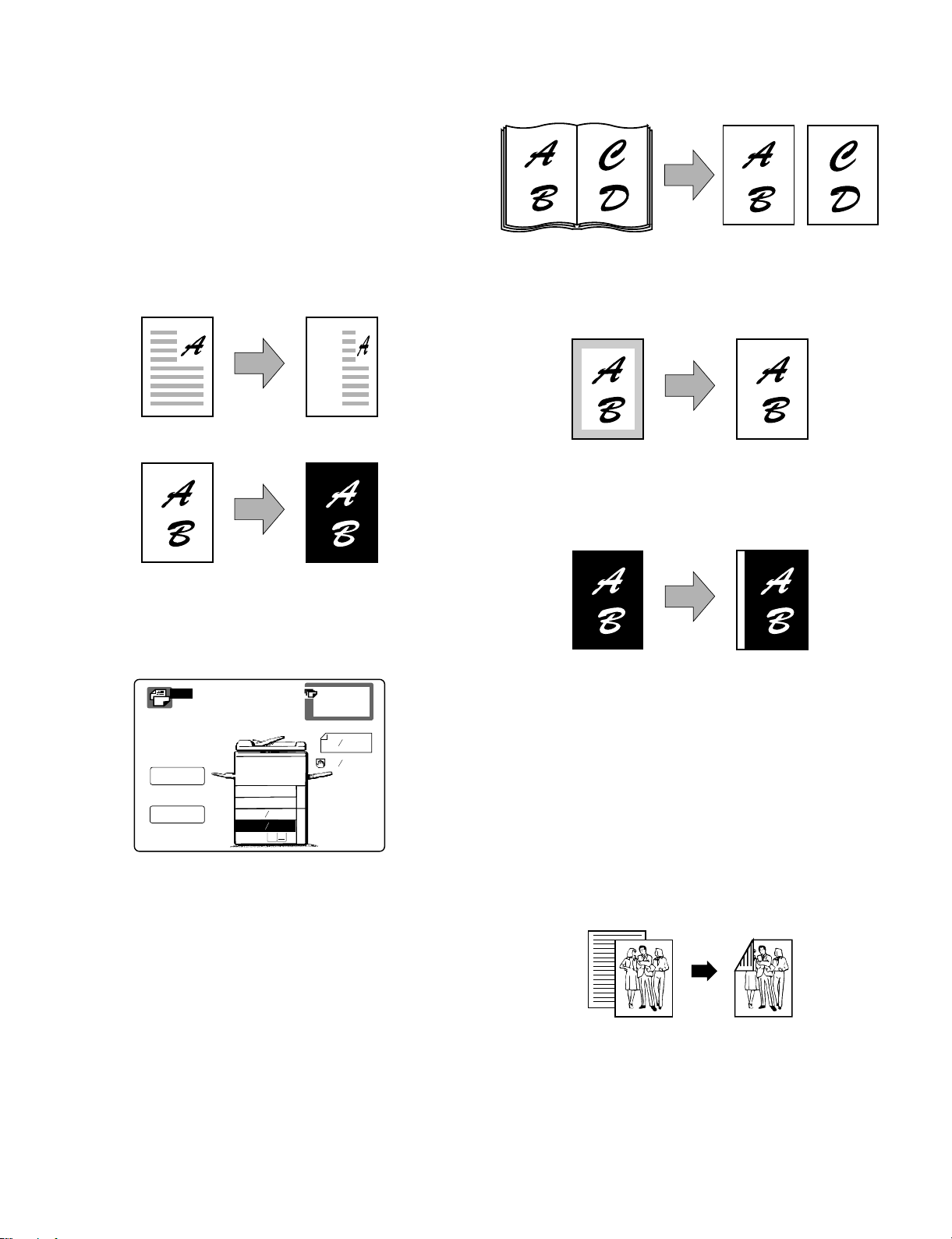
(1) Various functions in the digital system
Different from the conventional analog copiers, the original image
data scanned by the CCD sensor (which converts optical signals into
electrical signals) are converted into digital signals. With the printer kit
(option), in addition to copying functions, this machine can be connected with a computer to serve as a printer. The other features
include the independent zooming function and black-white reversing
function.
Independent z oomi ng copy
Black-white reversing copy
(6) 1-set 2-copy
The right and the left pages of a book, etc. can be copied into two
sheets of paper continuously.
(7) Edge erase copying
Shade at the copy edge can be automatically erased.
(6) Binding margin copying
Copying with binding margin can be made.
(2) Message screen
The message screen employs the LCD display with backlight, and
displays the operational descriptions and paper jam removal procedure, etc.
COPY
READY TO COPY.
COPY RATIO
100%
EXPOSURE
AUTO
AUTO PAPER
SELECT
DUPLEX
11X17
1.
1
2.
X14
8
2
1
3. 8
2
X11
0
ORIGINAL
1
X11
8
2
1
X11R
8
2
(3) Front loading paper tray
The paper trays including the two-step paper feed desk employ a
front loading system to facilitate paper loading.
(4) 351-step zooming by the electronic zooming
function
The electronic zooming function allows 351-step zooming from 50%
to 400% (1% increment).
(9) Copy conditions registration/recall
Nine sets of complicated copying procedures can be stored and
recalled when necessary.
(10) Key operator program
The key operator program is used by the key operator to set and
cancel the customer functions.
(11) Auto duplex copy
Duplex copy is made automatically.
Original Copy
(5) Paper/magnification ratio auto selection
When the desired magnification ratio is specified, the suitable paper
size is automatically selected by the original size detection function. If
the copy paper size is specified, then the suitable magnification ratio
is automatically selected.
1 – 1
Page 5
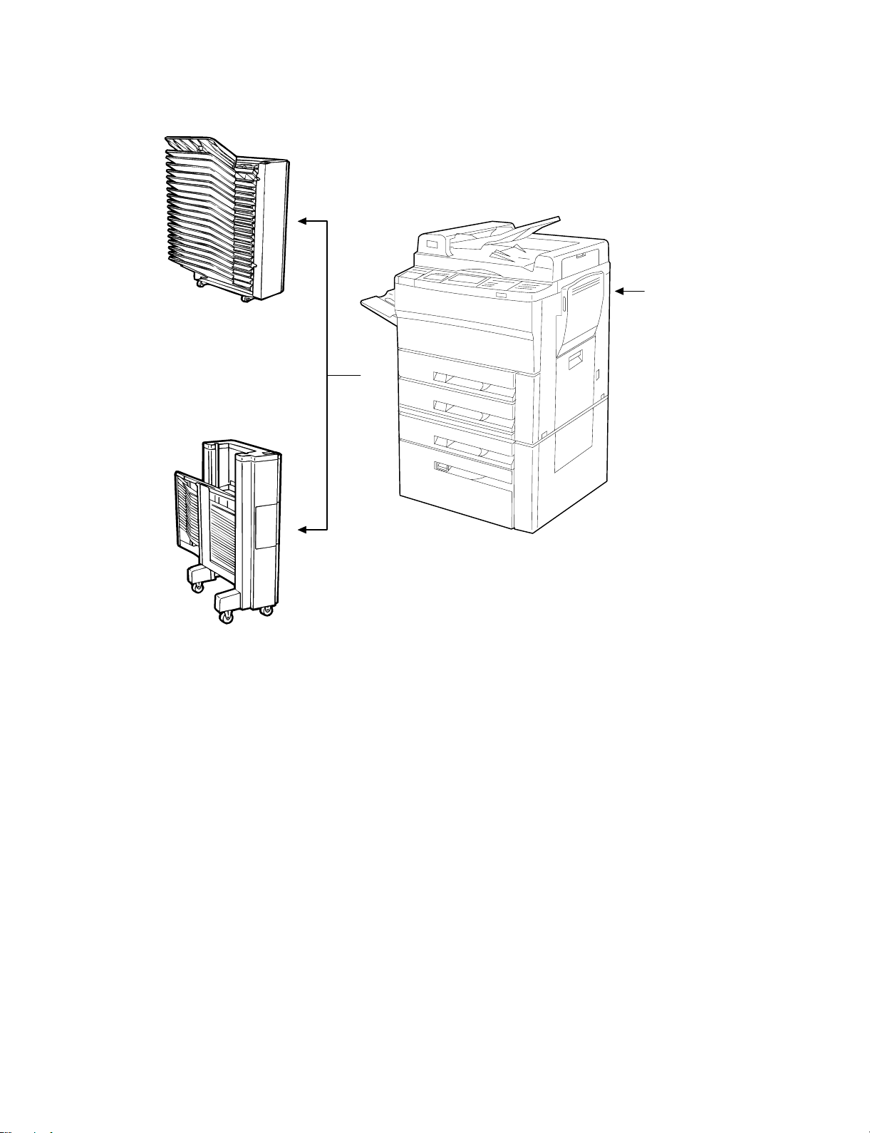
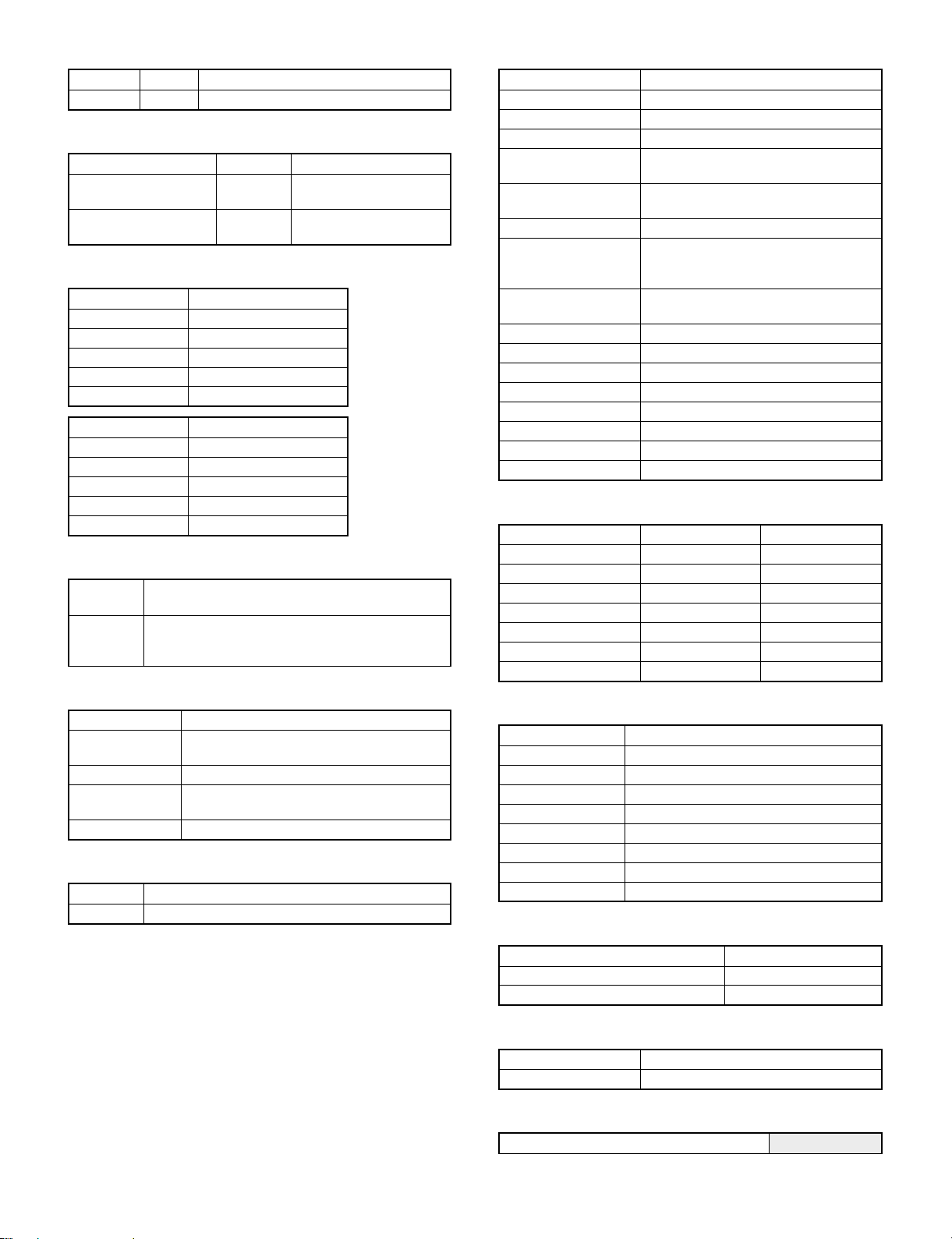
2. System outline (options)
20-bin sorter
(SF-S15)
Copied papers are sorted in the sequence
of pages or in each page automatically.
(Max. 20 sets of sorting is possible.)
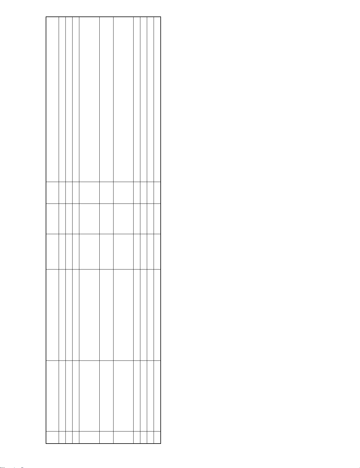
Staple sorter
(SF-S53N)
Printer kit
Connected to a computer
to allow the machine to
be used as a printer.
Copied papers are sorted in the sequence
of pages or in each page automatically.
(Max. 20 sets of sorting is possible.)
The sorted papers (in the sequence of
pages) can be stapled.
1 – 2
Page 6
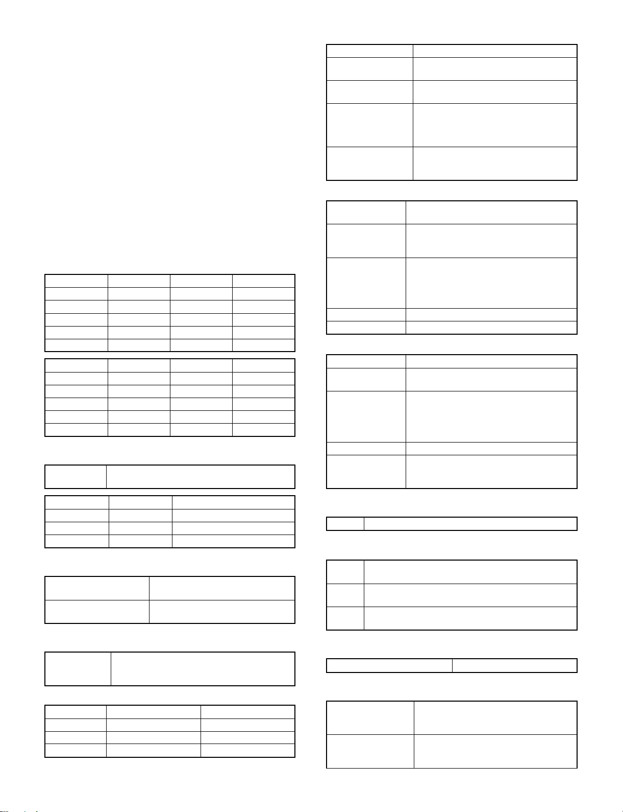
[2] SPECIFICATIONS
1. Basic specif icat io ns
(1) Type: Console
(The desk is standard equipment, but packaged
separately.)
(2) Copy system: Static electricity transfer, dry
copier
(3) Scanning system
Miniature optical, CCD linear sensor
Linear sequential scanning by light source
shifting
Basic scanning resolution: 400 dpi
(4) Copy speed
Paper size Normal Enlargement Reduction
Letter 32 17 23
W-letter 17 16 17
Legal 19 17 19
Letter-R 23 17 21
Invoice 32 17 23
Paper size Normal Enlargement Reduction
A4 32 17 23
A3 17 16 17
B4 19 17 19
A4R 23 17 21
A5 32 17 23
(5) First copy time
4.6 seconds When a sheet of A4 or letter size paper is fed
from the paper tray 1
1 Manual feed tray
Tray type Folding type (2-stage telescopic)
Copy paper size A3 ∼ A6R
Detectable paper size A3, B4, A4, A4R, A5
Feedable paper size Single feed: 56 ∼ 128 g/m
Special type of paper OHP with backing paper (backing paper is
W letter size ∼ invoice form
W-letter, Legal, Letter, Letter-R, Invoice
2
Multi feed: 56 ∼ 80 g/m2 (50 sheets)
(A4/Letter size or smaller when paper
weight is more than 104 g/m2)
removed when set), label paper, recycled
paper, blueprint paper, index paper
2 Paper tray 1/paper tray 2
Cassette type Paper tray 1: Inner type
Copy paper size A3 ∼ A5 (A5R is available only for inner type)
Size change To be performed only by service person
Paper tray 2: Integral with drawer
W letter size ∼ Invoice form
(Invoice form is available only for inner type)
• Changing regulating plate mounting position
• Moving size detection block
• Changing size display
Feedable paper size 56 ∼ 80 g/m2 (including recycled paper)
Capacity 500 sheets (total thickness: less than 54 mm)
3 Paper tray 3
Cassette type LCC (Large capacity cassette) type
Copy paper size A4
Size change To be performed only by service person
Letter
• Changing regulating plate mounting position
• Moving size detection block
• Changing size display
Feedable paper size 56 ∼ 80 g/m2 (including recycled paper)
Capacity 3000 sheets (1500 sheets for each stage)
Total thickness: less than 165 mm (Thickness
of 1500 sheets)
ADU No data ADU standard equipment
Paper tray 1 4.6 sec
Paper tray 2 5.3 sec
Paper tray 3 5.5 sec LCC
(6) Document
Max. document size 437 × 301 mm
(same for both AB/Inch systems)
Document positioning
reference point
Left center (when OC is used.)
(7) Paper feed
Paper feed port 500 sheets cassette × 2
Tray size (factory setting)
ADU ADU Standard
Paper tray 1 A3/W-letter Supplied as accessory
Paper tray 2 A4R/Legal
Paper tray 3 A4/Letter
3000 sheets cassette (LCC type)
Manual feed tray
(8) Job speed
S → S 32 sheets/min (10 documents and 1 copy per document)
Conditions: with duplex unit and without stapler
Excluding first copy.
S → D 20 surfaces/min (10 documents and 5 copies per
document)
D → D 20 surfaces/min (5 documents and 5 copies per
document)
D → S 25 surfaces/min (5 documents and 5 copies per
document)
(9) Multi copy mode
Maximum setting 999 copies
(10) Warm-up time
Power ON →
lighting of ready lamp
JAM recovery 10 sec. (reference value)
2 – 1
Approx. 90 sec.
Rated voltage input, ambient temperature
20°C, humidity 65%RH
(Varies depending on the fusing
temperature at which a paper jam occurs)
Page 7
(11) Fixed magnification
Inch series 10 steps 400, 200, 141, 129, 121, 100, 95, 77, 64, 50
AB series 10 steps 400, 200, 141, 122, 115, 100, 86, 81, 70, 50
(12) Zooming
Zooming 50 ∼ 400% Adjustable in steps of 1%
Independent zooming,
longitudinal
Independent zooming,
lateral
50 ∼ 400% Adjustable in steps of 1%
50 ∼ 400% Adjustable in steps of 1%
(13) Printing area
Paper size (mm)
A3 416 × 293
B4 360 × 253
A4 206 × 293
A4R 293 × 206
A5 144 × 206
Paper size (mm)
W Letter 428 × 275
Legal 352 × 212
Letter 212 × 275
Letter-R 275 × 212
Invoice 136 × 212
(14) Void area and image loss
Void area Less than 3 mm at leading edge, less than 3 mm at
trailing edge, less than 5 mm in the sum of both.
Image loss Less than 5 mm at leading edge, less than 5 mm at
sides of both leading and trailing edges
(at 100% magnification)
(15) ADU
Standard
Paper size A3, B4, A4, A4R, A5 (B5, B5R)
W-letter, Legal, Letter, Letter-R
Paper weight 56 ∼ 80 g/m
Capacity A4 ⋅ B5/Letter: 50 sheets
A3 ⋅ B4/W-letter, Legal: 30 sheets
Power source Supplied from the main body.
2
(16) Paper exit tray
Capacity 250 sheets
Sorter Option (For details, see optional specifications.)
(17) Additional functions
APS |
AMS |
Duplex copy |
Sorter Option
Copy condition
registration and call
Independent zooming 50 ∼ 400% in longitu dinal and lateral
1-set 2-copy Not available in enlargement mode
Binding margin Shift width: 9 mm, 3/8" (width is
Edge erase Width: 5 mm, 1/4"
Reverse video Entire surface only
Preheating function Adjustable by key operator program
Auto-power shut-off Adjustable by key operator program
Message display |
Guidance display | (images available)
Self-diagnostics |
Key operator program |
Process control |
9 copy functions
directions, each
adjustable, but binding direction is fixed)
(Setting by key operator program)
Adjustable by key operator program
(18) Machine configuration
Model
Main body AR-5132
RADF Standard
ADU Standard
DESK Standard
20 bin sorter SF-S15 Option
20 bin staple sorter SF-S53N Option
Printer kit AR-BD14 Option
(19) Other specifications
Photoconductor type OPC
OPC diameter 65 mm
Exposure lamp Halogen lamp
Developing 2-component inversion
Charging Scorotron
Transfer Corotron
Separation Corotron
Fusing Heat roller + separation pawl + cleaning roller
Cleaning Blade
(20) Appearance
Width × Depth × Height 638 × 680 × 1145 mm
Installation area (width × depth) 1236 × 680 mm
Weight About 143.9 kg
(21) Power supply
Power supply 120 V, 220 V ∼ 230 V, 240 V ±10%
Frequency 50/60 Hz
(22) Power consumption
Max. power consumption Less than 1.5 kW
2 – 2
Page 8
Package Remarks
name
Product
those supplied separately.
those supplied separately.
Fusing separation pawl (upper) × 4
Heat roller gear × 1
Fusing separation pawl (lower) × 2
Charging plate unit × 1
Drum separation pawl unit × 1
1 Drum OPC drum × 1 160 K AR-532DR 10
2 Developer (black) Developer (850 g) × 10 80 K (× 10) AR-532MD1 1 (AR-532ND1) × 10 = AR-532MD1
3 Toner (black) Toner cartridge (600 g) × 10 15 K (× 10) AR-532MT1 1 (AR-532NT1) × 10 = AR-532MT1
(1) SEC
NO. Name Description Life
2. Consumable parts
4 Upper heat roller kit Upper heat roller × 1 160 K AR-532UH 5 Replacement of fusing separation pawl for every 80 K should be done using
5 Lower heat roller kit Lower heat roller × 1 160 K SF-240LH 5 Replacement of fusing separation pawl for every 80 K should be done using
6 80K maintenance kit Cleaner blade × 1 80 K AR-532KA1 5
7 Cleaner blade Cleaner blade × 10 80 K (× 10) SF-222CB 1 (SF-228BL) × 10 = SF-222CB
8 Upper cleaning roller Upper cleaning roller × 10 80 K (× 10) SF-240UR 1 (SF-240RU) × 10 = SF-240UR
9 Lower cleaning roller Lower cleaning roller × 10 80 K (× 10) SF-235CR2 1 (SF-235RU) × 10 = SF-235CR2
10 Staple cartridge Staple cartridge × 5 5000 times × 5 SD-LS20 10 (SD-SC20) × 5 = SD-LS20
* When replacing parts other than those given above, use service parts.
2 – 3
Page 9

Package Remarks
name
Product
Order is received as SF-216LP.
Order is received as AR-532HG.
Order is received as SD-360LP.
Order is received as SF-240DP.
Order is received as AR-532SU.
Order is received as AR-532PU.
Order is received as SF-240BU.
Order is received as AR-532FL.
Order is received as AR-532CL.
Order is received as AR-532MC.
(2) SECL
1 Drum OPC drum × 1 160 K AR-532DR 10
2 Developer (black) Developer (850 g) × 10 80 K (× 10) AR-532MD1 1 (AR-532ND1) × 10 = AR-532MD1
NO. Name Description Life
Lower heat roller × 1
Toner receiving seal × 1
DV seal × 1
Heat roller gear × 1
3 Toner (black) Toner cartridge (600 g) × 10 15 K (× 10) AR-532MT1 1 (AR-532NT1) × 10 = AR-532MT1
4 160K maintenance kit Upper heat roller × 1 160 K AR-532KB 1
Lower cleaning roller × 1
Cleaner blade × 1
Toner recovery container × 4
Fusing separation pawl (upper) × 4
Fusing separation pawl (lower) × 2
Screen grid × 1
Charging plate unit × 1
Drum separation pawl unit × 1
5 80K maintenance kit Upper cleaning roller × 1 80 K AR-532KA 1
6 Staple cartridge Staple cartridge × 5 5000 times × 5 SD-LS20 10 (SD-SC20) × 5 = SD-LS20
7 Cleaner blade Cleaner blade × 10 80 K (× 10) SF-222CB 1 (SF-228BL) × 10 = SF-222CB
8 Upper cleaning roller Upper cleaning roller × 10 80 K (× 10) SF-240UR 1 (SF-240RU) × 10 = SF-240UR
9 Lower cleaning roller Lower cleaning roller × 10 80 K (× 10) SF-235CR2 1 (SF-235RU) × 10 = SF-235CR2
2 – 4
10 Upper heat roller Upper heat roller × 1 160 K AR-532HU 5
11 Fusing separation pawl (upper) Fusing separation pawl (upper) × 4 × 10 80 K (× 10) SF-216UP 1 SF-216LP = (SF-216MP) × 10 SF-216MP is supplied 4 pcs. for 1 copier.
12 Heat roller gear Heat roller gear × 10 160 K (× 10) AR-532HG 1 AR-532HG = (AR-532JG) × 10
13 Lower heat roller Lower heat roller × 1 160 K SF-240HR 5
14 Fusing separation pawl (lower) Fusing separation pawl (lower) × 2 × 10 80 K (× 10) SD-360LP 1 SD-360LP = (SD-360MP) × 10 SD-360MP is supplied 2 pcs. for 1 copier.
15 Drum separation pawl Drum separation pawl × 2 × 10 80 K (× 10) SF-240DP 1 SF-240DP = (SF-240EP) × 10 SF-240EP is supplied 2 pcs. for 1 copier.
16 Screen grid Screen grid × 10 80 K (× 10) AR-532SU 1 AR-532SU = (AR-532TU) × 10
17 Charging plate Charging plate × 10 80 K (× 10) AR-532PU 1 AR-532PU = (AR-532NU) × 10
18 Waste toner bottle Waste toner bottle × 1 SF-240TB 5
19 Heat insulation bushing Heat insulation bushing × 2 × 10 160 K (× 10) SF-240BU 1 SF-240BU = (SF-240DU) × 10
20 Ozone filter Ozone filter × 10 80 K (× 10) AR-532FL 1 AR-532FL = (AR-532JL) × 10
21 Copy lamp Copy lamp × 10 AR-532CL 1 AR-532CL = (AR-532DL) × 10
22 MC case MC case × 10 AR-532MC 1 AR-532MC = (AR-532NC) × 10
* When replacing parts other than those given above, use service parts.
Page 10

Package Remarks
name
Product
Order is received as SF-216UP.
Order is received as AR-532HG.
Order is received as SD-360LP.
Order is received as SF-240DP.
Order is received as AR-532SU.
Order is received as AR-532PU.
Order is received as SF-240BU.
Order is received as AR-532FL.
Order is received as AR-532CL.
Order is received as AR-532MC.
NO. Name Description Life
(3) Europe
1 Drum OPC drum × 1 160 K AR-532DM 10
2 Developer (black) Developer (850 g) × 10 80 K (× 10) AR-532LD1 1 (AR-532DV1) × 10 = AR-532LD1
3 Toner (black) Toner cartridge (600 g) × 10 15 K (× 10) AR-532LT1 1 (AR-532T1) × 10 = AR-532LT1
4 160K maintenance kit Upper heat roller × 1 160 K AR-532KB 1
Lower heat roller × 1
Toner receiving seal × 1
DV seal × 1
Heat roller gear × 1
Lower cleaning roller × 1
Cleaner blade × 1
Toner recovery container × 4
Fusing separation pawl (upper) × 4
Fusing separation pawl (lower) × 2
Screen grid × 1
Charging plate unit × 1
Drum separation pawl unit × 1
5 80K maintenance kit Upper cleaning roller × 1 80 K AR-532KA 1
6 Staple cartridge Staple cartridge × 5 5000 times × 5 SD-LS20 10 (SD-SC20) × 5 = SD-LS20
7 Cleaner blade Cleaner blade × 10 80 K (× 10) SF-222CB 1 (SF-228BL) × 10 = SF-222CB
8 Upper cleaning roller Upper cleaning roller × 10 80 K (× 10) SF-240UR 1 (SF-240RU) × 10 = SF-240UR
9 Lower cleaning roller Lower cleaning roller × 10 80 K (× 10) SF-235CR2 1 (SF-235RU) × 10 = SF-235CR2
2 – 5
10 Upper heat roller Upper heat roller × 1 160 K AR-532HU 5
11 Fusing separation pawl (upper) × 10 80 K (× 10) SF-216UP 1 SF-216UP = (SF-216TP) × 10 SF-216TP is supplied 4 pcs. for 1 copier.
12 Heat roller gear Heat roller gear × 10 160 K (× 10) AR-532HG 1 AR-532HG = (AR-532JG) × 10
13 Lower heat roller Lower heat roller × 1 160 K SF-240HR 5
14 Fusing separation pawl (lower) Fusing separation pawl (lower) × 2 × 10 80K (× 10) SD-360LP 1 SD-360LP = (SD-360MP) × 10 SD-360MP is supplied 2 pcs. for 1 copier.
15 Drum separation pawl Drum separation pawl × 2 × 10 80 K (× 10) SF-240DP 1 SF-240DP = (SF-240EP) × 10 SF-240EP is supplied 2 pcs. for 1 copier.
16 Screen grid Screen grid × 10 80 K (× 10) AR-532SU 1 AR-532SU = (AR-532TU) × 10
17 Charging plate Charging plate × 10 80 K (× 10) AR-532PU 1 AR-532PU = (AR-532NU) × 10
18 Waste toner bottle Waste toner bottle × 1 SF-240TB 5
19 Heat insulation bushing Heat insulation bushing × 2 × 10 160 K (× 10) SF-240BU 1 SF-240BU = (SF-240DU) × 10
20 Ozone filter Ozone filter × 10 80 K (× 10) AR-532FL 1 AR-532FL = (AR-532JL) × 10
21 Copy lamp Copy lamp × 10 AR-532CL 1 AR-532CL = (AR-532DL) × 10
22 MC case MC case × 10 AR-532MC 1 AR-532MC = (AR-532NC) × 10
* When replacing parts other than those given above, use service parts.
Page 11

Package Remarks
name
Product
Order is received as SF-216UP.
Order is received as AR-532HG.
Order is received as SD-360LP.
Order is received as SF-240DP.
Order is received as AR-532SU.
Order is received as AR-532PU.
Order is received as SF-240BU.
Order is received as AR-532FL.
Order is received as AR-532CL.
Order is received as AR-532MC.
(4) SCA
NO. Name Description Life
1 Drum OPC drum × 1 160 K AR-532DM 10
Lower heat roller × 1
Toner receiving seal × 1
2 Developer (black) Developer (850 g) × 10 80 K (× 10) AR-532LD1 1 (AR-532DV1) × 10 = AR-532LD1
3 Toner (black) Toner cartridge (600 g) × 10 15 K (× 10) AR-532LT1 1 (AR-532T1) × 10 = AR-532LT1
4 160K maintenance kit Upper heat roller × 1 160 K AR-532KB 1
DV seal × 1
Heat roller gear × 1
Lower cleaning roller × 1
Cleaner blade × 1
Toner recovery container × 4
Fusing separation pawl (upper) × 4
Fusing separation pawl (lower) × 2
Screen grid × 1
Charging plate unit × 1
Drum separation pawl unit × 1
5 80K maintenance kit Upper cleaning roller × 1 80 K AR-532KA 1
6 Staple cartridge Staple cartridge × 5 5000 times × 5 SD-LS20 10 (SD-SC20) × 5 = SD-LS20
7 Cleaner blade Cleaner blade × 10 80 K (× 10) SF-222CB 1 (SF-228BL) × 10 = SF-222CB
8 Upper cleaning roller Upper cleaning roller × 10 80 K (× 10) SF-240UR 1 (SF-240RU) × 10 = SF-240UR
9 Lower cleaning roller Lower cleaning roller × 10 80 K (× 10) SF-235CR2 1 (SF-235RU) × 10 = SF-235CR2
2 – 6
10 Upper heat roller Upper heat roller × 1 160 K AR-532HU 5
11 Fusing separation pawl (upper) Fusing separation pawl (upper) × 4 × 10 80 K (× 10) SF-216UP 1 SF-216UP = (SF-216TP) × 10 SF-216TP is supplied 4 pcs. for 1 copier.
12 Heat roller gear Heat roller gear × 10 160 K (× 10) AR-532HG 1 AR-532HG = (AR-532JG) × 10
13 Lower heat roller Lower heat roller × 1 160 K SF-240HR 5
14 Fusing separation pawl (lower) Fusing separation pawl (lower) × 2 × 10 80 K (× 10) SD-360LP 1 SD-360LP = (SD-360MP) × 10 SD-360MP is supplied 2 pcs. for 1 copier.
15 Drum separation pawl Drum separation pawl × 2 × 10 80 K (× 10) SF-240DP 1 SF-240DP = (SF-240EP) × 10 SF-240EP is supplied 2 pcs. for 1 copier.
16 Screen grid Screen grid × 10 80 K (× 10) AR-532SU 1 AR-532SU = (AR-532TU) × 10
17 Charging plate Charging plate × 10 80 K (× 10) AR-532PU 1 AF-532PU = (AR-532NU) × 10
18 Waste toner bottle Waste toner bottle × 1 SF-240TB 5
19 Heat insulation bushing Heat insulation bushing × 2 × 10 160 K (× 10) SF-240BU 1 SF-240BU = (SF-240DU) × 10
20 Ozone filter Ozone filter × 10 80 K (× 10) AR-532FL 1 AR-532FL = (AR-532JL) × 10
21 Copy lamp Copy lamp × 10 AR-532CL 1 AR-532CL = (AR-532DL) × 10
22 MC case MC case × 10 AR-532MC 1 AR-532MC = (AR-532NC) × 10
* When replacing parts other than those given above, use service parts.
Page 12
[3] OPTIONS SPECIFI C ATIONS
1. SF-S15
2. SF-S53N
Name 20-bin sorter
No. of bins 20 bins
Paper collection Copy face up
Capacity per bin Max. 50 sheets (100 sheets: Top bin)
Allowable paper size/weight
for collating
Power source Supplied from the copier.
Dimensions 500mm (W) × 520mm (D) × 957mm (H)
Weight About 13kg
Name Staple sorter
No. of bins 20 bins
Paper collection Copy face up
Capacity per bin Max. 50 sheets (250 sheets: Top bin)
Allowable paper size/weight
for collating
No. of sheets for stapling 50 sheets (80g/m2)
Power source Supplied from the copier.
Dimensions 475mm (W) × 597mm (D) × 995mm (H)
Weight About 42.1kg
Max. A3, Min.: B5 (Min. A6 for non-sort)
Non-sort: 52 ∼ 128g/m2,
Sort/Grouping: 56 ∼ 80g/m
Max.: A3, Min.: B5 (Non-sort: Min. A5),
Non-sort: 52 ∼ 128g/m2,
Sort/staple sort/grouping: 56 ∼ 89g/m
2
2
3 – 1
Page 13
[4] PART NAME AND FUNCTION
1
2 3 4 5
6
7 8 9
10
11
12 13
14 15 16 17
18
19
20
21
22
23 24
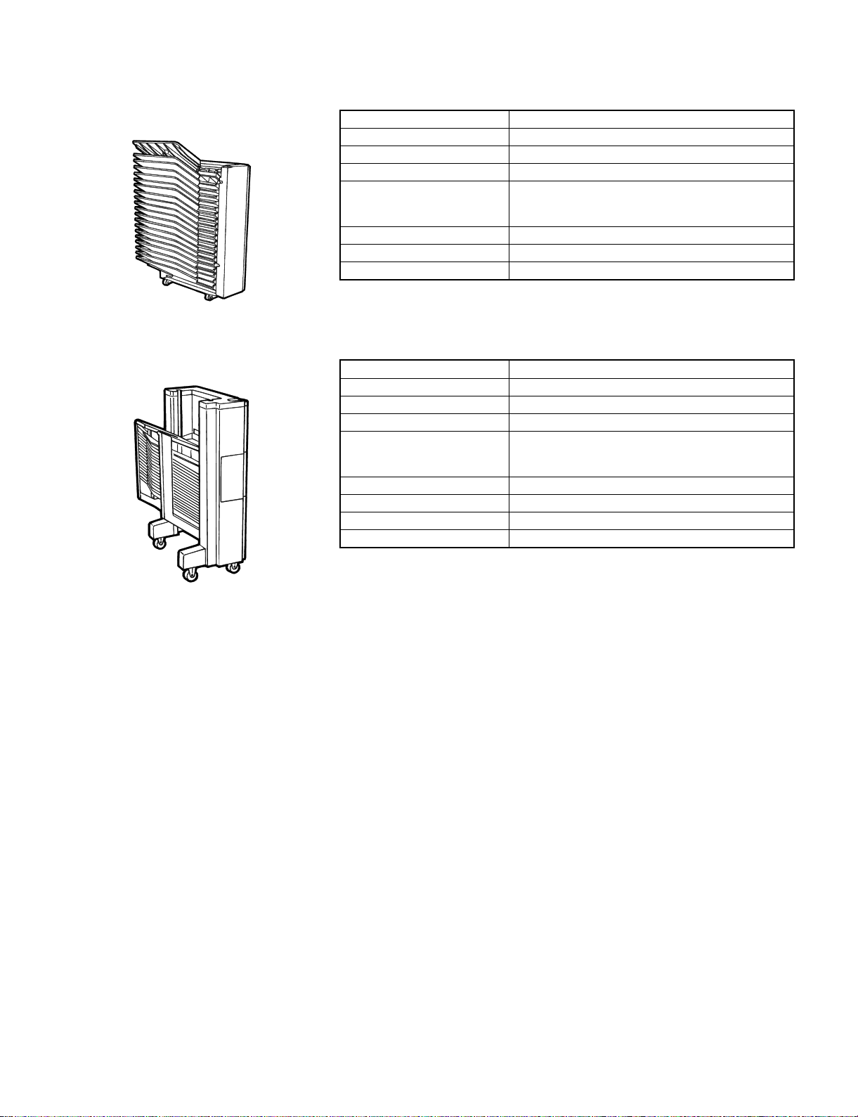
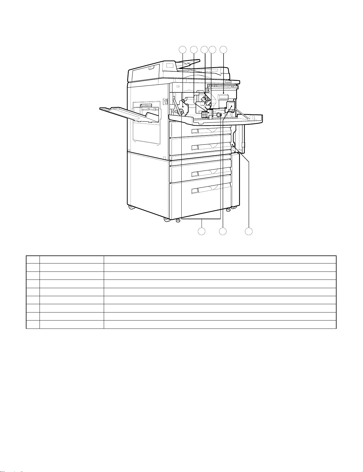
1. External view
No. Name Function
Exit tray Finished copies are deposited in the exit tray.
1
Paper clip tray Keep paper clip here.
2
Document feeder indicator Indicate document feeder condition.
3
RADF feeding roller cover Open to remove misfed documents.
4
Operation panel All copier controls are located here for easy operation.
5
Document guides Adjust to the size of the documents.
6
Document feeder tray Holds up to 50 documents.
7
Document feeder cover Open to make copies from the document glass.
8
Document glass All documents which cannot be copied from the RADF must be copied here.
9
RADF exit area Finished documents are output here.
F
RADF exit roller cover Open to remove misfed documents.
G
Manual feed tray paper guides Adjust to the width of the copy paper.
H
Manual feed tray Special papers (including transparency film) and copy paper can be fed from the manual feed tray.
I
Exit area cover Open to remove misfed paper.
J
Power switch Press to turn copier power on and off.
K
Duplex module The duplex module provides duplex copying capability.
L
Paper tray 1 Holds 500 sheets of 20 lb. bond paper. Copy paper size can be changed by changing the inner cassette.
M
Paper tray 2 Holds 500 sheets of 20 lb. bond paper.
N
Paper tray 3 Holds A4 or letter sized paper. Tray capacity is 3,000 sheets of 20 lb. bond paper.
O
Front cover Open to remove misfeeds and to service the copier.
P
Waste toner bottle cover Open to replace the Waste toner bottle.
Q
Handles Pull out to move the copier.
R
Upper side cover Open to remove misfeeds in the paper feed area.
S
Lower side cover Open to remove misfeeds in paper tray 2 and 3.
T
4 – 1
Page 14
2. Internal structure
1 5
6 7
8
2 3 4
No. Name Function
Fusing unit Fuses toner to paper.
1
Transport level Turn to open the paper transport section.
2
Corona unit The unit is used to charge the photoconductive drum.
3
Photoconductive drum Copy images are formed on the photoconductive drum.
4
Toner hopper Contains toner.
5
Roller rotating knobs Turn to remove misfed paper.
6
Toner hopper lock lever Pull down release the toner hopper.
7
Waste toner bottle Waste toner is collected here. Replace when a message appears in the display indicating the need to do so.
8
4 – 2
Page 15
There keys are not used for
the copier features.
PRINTE R
CA
ON LINE
COPY
CLEAR ALL
START
343332313029
10 11 12 13
3 4 5 6 7 8 9
2
P
INTERRUPT
PROGRAM
?
INFORMATIO N
SCROLL DISPLAY
0
ORIGINAL
READY TO COPY.
COPY
DUAL PAGE
COPY
EDGE
ERASE
MARGIN
SHIFT
B/W
REVERSE
XY-
ZOOM
X11
X11R
2
2
1
1
8
8
AUTO PAPER
COPY RATIO
AUTO
IMAGE
2
ORIGINAL TO COPY
11
23
1
456
X11
X14
2
2
1
1
11X17
8
SELECT
DUPLEX
1.
2. 8
3.
AUTO
100%
EXPOSURE
ZOOM
122
1
2
ODD
NUMBER
PRE-COUNT
ORIGINALS
EVEN
NUMBER
(ORIGINALS)
8
7
100%
GROUP
SORTER
STAPLE
SORT
C
0/
AUDIT CLEAR
TRAY SELECT
DARK
LIGHT
EXPOSURE
AUTO
MANUAL
PHOTO
SORT
28
27262524232220 21191817
16
1514
9
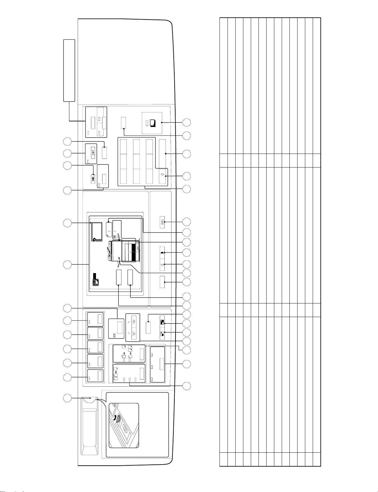
Light key
Dark key
Tray and paper size display
Original size display
Paper tray select key
Ten key pad
Auditor clear key
Clear key
U
V
W
X
Y
Z
[
\
Program
Original to copy key and indicator
Sorter key and indicator
Original to copy key and indicator
Zoom key
Reduction key
Enlargement key
100% key
I
J
K
L
M
N
O
P
Clear all key
Start key and indicator
]
^
Copy ratio display
Exposure display
Exposure key
Auto paper select display
Q
R
S
T
1
the
of
adjust-
best suit
to
display
vary the contrast
to
LCD contrast control
Use the contrast control
ment
message
the room lighting conditions.
3. Operation panel
LCD contrast volume
XY-zoom
Black white reverse
Margin shift
1
2
3
No. Name No. Name No. Name
4
Edge erase
Dual page copy
Auto image
5
6
7
LCD display
Copy quantity display
Operation information
Scroll display
Interrupt key and indicator
8
9
F
G
H
4 – 3
Page 16
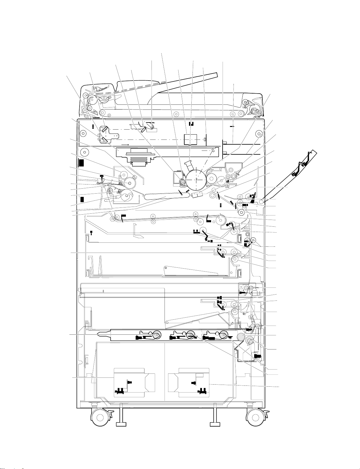
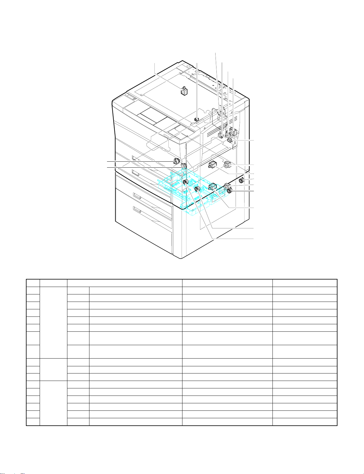
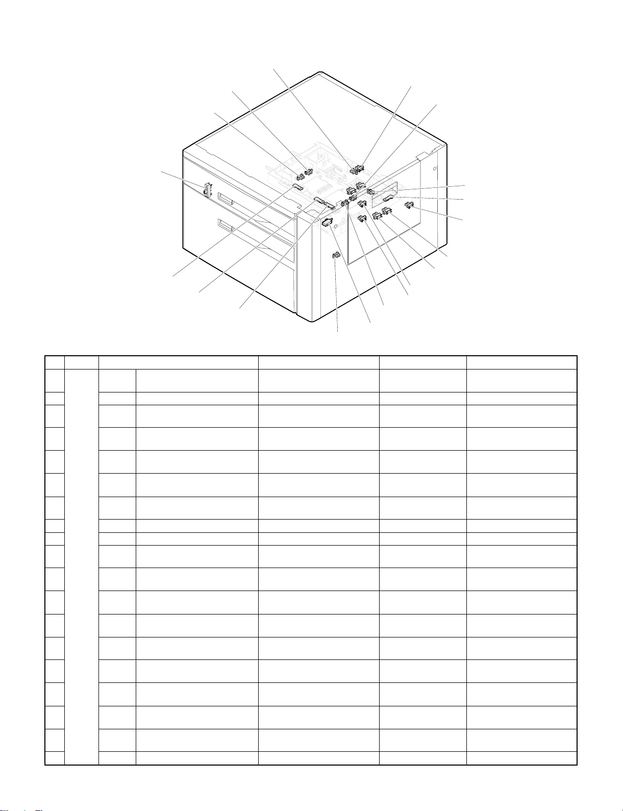
4. Major parts
3.3rd mirror
12.Drum separation unit
2.2nd mi r r or
10.Copy lamp
1.1st m ir r or
9.Cleaner unit
20.Main charger unit
16.Lens unit
24.Mother PWB
8.CCD PWB
15.ICU PWB
25.OPC drum
19.LSU
13.Fuser thermistor
50.Upper cleaning roller
51.Upper heat roller
14.Heater lamp
26.Paper exit select gate
52.Upper separation pawl
18.Lower sepatation pawl
17.Lower heat roller
46.Suction unit
45.Suction belt
28.Paper tray 1
pick-up roller
40.Printer PWB (option)
11.Developer unit
47.Transfer charger
44.Separation
charger
41.Res i st roll er
21.Manual feed pap er
feed roller
22.Manual feed pick-up roler
23.Manual feed separation roller
49.Transport roller (upper)
6.ADU reverse roller
5.ADU pi c k - u p ro l l er
7.ADU separation roller
48.Transport roler (lower)
4.ADU paper feed roller
27.Paper tray paper feed roller
29.Paper tray 1 separation roller
43.Resist roller (desk upper)
31.Paper tray 2 pick-up roler
30.Paper tray 2 paper feed roller
37.Paper tray 3
pick-up roller 2
34.Paper tray 3
lift-up unit 2
32.Paper tray 2 separation roller
42.Resist roller (desk lower)
35.Pap er tray 3 paper feed roller
38.Pap er t ra y 3 s eparation r o ller
36.Paper tray 3 pick-up roller 1
39.Paper tray 3 transport roller
33.Paper tray 3 lift-up unit 1
4 – 4
Page 17

No. Part name No. Part name No. Part name
1 1st mirror 19 LSU 37 Paper tray 3 pick-up roller 2
2 2nd mirror 20 Main charger unit 38 Paper tray 3 separation roller
3 3rd mirror 21 Manual feed paper feed roller 39 Paper tray 3 transport roller
4 ADU paper feed roller 22 Manual feed pick-up roller 40 Printer PWB (Option)
5 ADU pick-up roller 23 Manual feed separation roller 41 Resist roller
6 ADU reverse roller 24 Mother PWB 42 Resist roller (desk-lower)
7 ADU separation roller 25 OPC drum 43 Resist roller (desk-upper)
8 CCD PWB 26 Paper exit select gate 44 Separation charger
9 Cleaner unit 27 Paper tray 1 paper feed roller 45 Suction belt
10 Copy lamp 28 Paper tray 1 pick-up roller 46 Suction unit
11 Developer unit 29 Paper tray 1 separation roller 47 Transfer charger
12 Drum separation unit 30 Paper tray 2 paper feed roller 48 Transport roller (lower)
13 Fuser thermistor 31 Paper tray 2 pick-up roller 49 Transport roller (upper)
14 Heater lamp 32 Paper tray 2 separation roller 50 Upper cleaning roller
15 ICU PWB 33 Paper tray 3 lift-up unit 1 51 Upper heat roller
16 Lens unit 34 Paper tray 3 lift-up unit 2 52 Upper separation pawl
17 Lower heat roller 35 Paper tray 3 paper feed roller 53
18 Lower separation pawl 36 Paper tray 3 pick-up roller 1 54
4 – 5
Page 18
5. Sensor
7.MHPS
2.CSWF
10.P-SW
15.POD
3.CSWL
21.DPPD1
18.PSD
23.DTBHPS
34.DPTD2
41.LMS2
31.DLUD2
38.E2CLK 40.LMS1
30.DLUD1
37.E1CLK
8.MPED
16.PPD1
17.PPD2
1.BD
5.IR
9.OCSW
14.PLS2
13.PLS1
19.TFD
22.DPPD2
20.DPFD
25.DTWHPS
24.DTPID
4.CSWR
12.PID
6.LUD2
11.PED3
33.DPOD1
42.LUD3
43.PED3
34.DPOD2
27.DLPD1
26.DDOP
39.F/LSW
29.DLPD332.DPE2
28.DLPD2
35.DPTD1
4 – 6
Page 19

No Section Name Function Contact / output
1 Main body BD Laser beam sensor Detection of laser beam start position
2 CSWF Door switch Front Front door open / close detection ON when closed
3 CSWL Door switch L Left door open / close detection ON when closed
4 CSWR Door switch R Right door open / close detection ON when closed
5 IR Optical communication light-receiving sensor Optical communication module for PDA/ZR
6 LUD2 Paper tray 1 lift-up sensor Detection of paper tray 1 lift-up upper limit Low when lift plate detected
7 MHPS Mirror home position sensor Detection of mirror unit home position High at home position
8 MPED Manual feed tray paper empty detector Detection of paper in manual feed tray Low when paper is detected
9 OCSW OC switch Detection of OC cover operation Low when cover is open
10 P-SW Main Power switch Main power ON / OFF
11 PED3 Paper tray 1 paper empty sensor Detection of paper in paper tray 1 Low when paper is detected
12 PID Paper in sensor Detection of paper in cassette High when paper pass over
13 PLS1 Manual feed tray paper length sensor 1 Manual feed tray paper length sensor 1 Low when detected
14 PLS2 Manual feed tray paper length sensor 2 Manual feed tray paper length sensor 2 Low when detected
15 POD Paper exit sensor Detection of paper exit from fusing section Low when paper pass over
16 PPD1 Paper pass detector 1 Paper transport detection 1 Low when paper pass over
17 PPD2 Paper pass detector 2 Paper transport detection 2 Low when paper pass over
18 PSD Paper separation detector Detection of paper separation on the OPC drum Low when paper pass over
19 TFD Waste toner sensor Waste toner bottle full detection Low when full waste toner detected
20 ADU DPFD ADU paper exit detector Detecton of paper exit from ADU High when paper pass over
21 DPPD1 ADU Paper feed sensor 1 Detection of Paper feed in ADU position 1 High when paper pass over
22 DPPD2 ADU Paper feed sensor 2 Detection of Paper feed in ADU position 2 High when paper pass over
23 DTBHPS ADU rear plate home position sensor Detection of ADU rear plate home position Low at home position
24 DTPID ADU Tray sensor Detection of paper in ADU High when paper is detected
25 DTWHPS ADU alignment plate home position sensor Detection of ADU alignment plate home position Low at home position
26 Desk unit DDOP Desk side open/close sensor Desk side door open / close detection Low when desk side door is open
27 DLPD1 Desk paper pass sensor 0 Paper transport detection 0 High when paper pass over
28 DLPD2 Paper tray 3 paper pass sensor 1 Paper transport detection 1 High when paper pass over
29 DLPD3 Paper tray 3 paper pass sensor 2 Paper transport detection 2 High when paper pass over
30 DLUD1 Paper tray 3 lift-up sensor 1 Detection of paper tray 3 lift-up upper limit High when interrupted
31 DLUD2 Paper tray 3 lift-up sensor 2 Detection of paper tray 3 lift-up upper limit High when interrupted
32 DPE2 Paper tray 3 paper empty sensor Detection of paper in paper tray 3 High when paper is detected
33 DPOD1 Desk unit resist sensor 1 Paper pass detection 1 Low when paper is detected
34 DPOD2 Desk unit resist sensor 2 Paper pass detection 2 Low when paper is detected
35 DPTD1 Paper tray 3 paper quantity sensor 1 Detection of paper quantity in paper tray 3
36 DPTD2 Paper tray 3 paper quantity sensor 2 Detection of paper quantity in paper tray 3
37 E1CLK Paper tray 3 lift-up motor 1 encoder clock detector Lift-up motor encoder clock detection Pulse output
38 E2CLK Paper tray 3 lift-up motor 2 encoder clock detector Lift-up motor encoder clock detection Pulse output
39 F/LSW Front loading open/close switch Paper tray 3 open / close detection High when open
40
41
42 LUD3 Paper tray 2 lift-up sensor Detection of paper tray 2 lift-up upper limit Low when lift plate detected
43 PED3 Paper tray 2 paper empty sensor Detection of paper in paper tray 2 Low when paper is detected
LMS1 Limit sensor 1 Prevention against excessive height of cassette
paper.
LMS2 Limit sensor 2 Prevention against excessive height of cassette
paper.
High when interrupted
High when interrupted
4 – 7
Page 20
6. Clutches and solenoid
3.DGS
5.PSPS
9.DDC
6.RRC
8.TRCL
7.TRCH
4.MPFS
10.DPFC
11.DRRC
No. Section Name Function Type
1 Main body CPFC2 Paper tray 1 pick-up clutch Paper tray 1 pickup roller rotation Electromagnetic clutch
2 CPFS2 Paper tray 1 pick-up solenoid Paper tray 1 pickup roller pressing Electromagnetic solenoid
3 DGS Duplex gate solenoid Duplex gate rotation drive Electromagnetic solenoid
4 MPFS Manual feed tray pick-up solenoid Manual feed roller pressing Electromagnetic solenoid
5 PSPS Paper separate solenoid Separation roller pressing Electromagnetic solenoid
6 RRC Resist roller clutch Resist roller rotation Electromagnetic clutch
7
8
9 ADU DDC ADU drive clutch ADU drive Electromagnetic clutch
10 DPFC ADU paper feed clutch ADU paper feed roller rotation Electromagnetic clutch
11 DRRC ADU counter roller clutch ADU counter roller rotation Electromagnetic clutch
12 Desk unit BCL Paper tray 3 separation clutch Paper tray 3 separation roller rotation Electromagnetic clutch
13 DPFC1 Paper tray 2 pick-up clutch Paper tray 2 pickup roller rotation Electromagnetic solenoid
14 DPFS1 Paper tray 2 pick-up solenoid Paper tray 2 pickup roller pressing Electromagnetic solenoid
16 P1CL Paper tray 3 pick-up roller 1 clutch Paper tray 3 pickup roller 1 rotation Electromagnetic clutch
17 P2CL Paper tray 3 pick-up roller 2 clutch Paper tray 3 pickup roller 2 rotation Electromagnetic clutch
18 RCL Paper tray 3 resist roller clutch Paper tray 3 resist roller rotation Electromagnetic clutch
TRCH Paper transport roller clutch (High speed) Paper transport roller rotation (High
speed)
TRCL Paper transport roller clutch (Low speed) Paper transport roller rotation (Low
speed)
1.CRFC2
2.CPFS2
18.RCL
13.DPFC1
12.BCL
14.DPF S1
16.P1CL
17.P2CL
Electromagnetic clutch
Electromagnetic clutch
4 – 8
Page 21
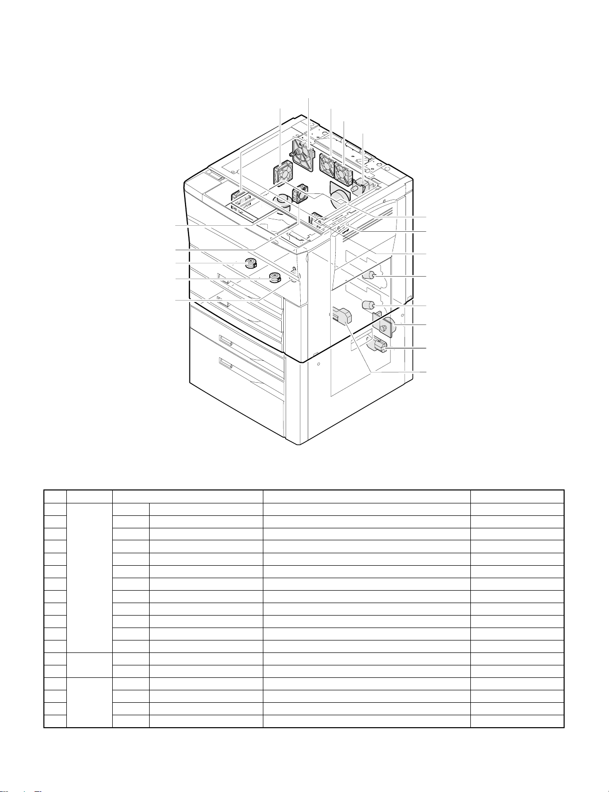
7. Motor
12.VFM
10.SM
1.CFM
4.LFM
3.DM
6.MM
9.SFM
2.DFM
5.LUM1
17.HMOT
15.E1MOT
18.LUM2
16.E2MOT
8.PM
7.PCFM
14.PAM2
13.PAM1
11.TM
No. Section Name Function Type
1 Main body CFM Cooling fan motor Optical system cooling DC brushless motor
2 DFM Power supply motor Power supply cooling DC brushless motor
3 DM Drum motor OPC drum, developing section drive DC brushless motor
4 LFM Process cooling fan motor Process control section cooling DC brushless motor
5 LUM1 Paper tray 1 lift-up motor Paper tray 1 lift-up DC motor
6 MM Main motor Paper feed, transport section drive DC brushless motor
7 PCFM Polygon cooling fan motor Polygon motor cooling DC brushless motor
8 PM Polygon motor Polygon mirror drive DC brushless motor
9 SFM Suction fan motor Suction unit cooling DC brushless motor
10 SM Mirror motor Scanner unit drive DC brushless motor
11 TM Toner motor Toner supply DC brushless motor
12 VFM Ventilation fan motor Ozone discharge DC brushless motor
13 ADU PAM1 ADU alignment plate motor ADU alignment plate drive DC stepping motor
14 PAM2 ADU rear plate motor ADU rear plate drive DC stepping motor
15 Desk unit E1MOT Paper tray 3 lift-up motor 1 Paper tray 3 lift-up DC motor
16 E2MOT Paper tray 3 lift-up motor 2 Paper tray 3 lift-up DC motor
17 HMOT Paper tray 3 transport motor Paper tray 3 paper transport DC brushless motor
18 LUM2 Paper tray 2 lift-up motor Paper tray 2 lift-up DC motor
4 – 9
Page 22
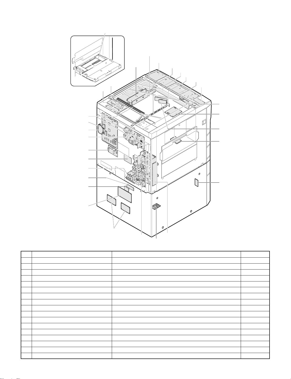
8. PWB unit
23.Manual feed tray paper size sensor PWB
24.Mother PWB
18.ICU PWB
30.Printer PWB
9.CCD drive PWB
25.Ope r at ion co ntrol PWB
13.Discharge lamp PWB
15.Docum ent size sensor PWB (Rec iev e side)
28.Process control volume PWB
21.LCD inverter PWB
20.LCD cont r ol PWB
22.LCD volume PWB
14.Doc ument size sensor PWB (Emit side)
29.Intreface PWB
26.PCU PWB
17.High voltage PWB
16.Drum motor PWB
1.Paper tray1 PWB
7.AC power supply (200V only)
2.Paper t ray2 cass et t e size sensor PWB
3.Paper tray2 lift up motor PWB
12.Desk main PWB
5.Paper tray3 lift up motor PWB
6.AC power supply
(200V: NF PWB)
10.DC power supply
11.Desk drive PWB
27.Polyg on motor drive P WB
19.Laser drive PWB
8.ADU PWB
4.Paper tray3 cassette size
swit ch PWB
No. Name Function
1 Paper tray 1 PWB Paper tray 1 paper size detection/Lift up motor drive
2 Paper tray 2 cassette size sensor PWB Paper tray 2 paper size detection
3 Paper tray 2 lift up motor PWB Lift up motor drive
4 Paper tray 3 cassette size switch PWB Paper tray 3 paper size setting
5 Paper tray 3 lift up motor PWB Lift up motor drive
6 AC power supply (200V: NF PWB) AC voltage supply (200V: Noise filter)
7 AC power supply (200V only) AC voltage supply (200V only)
8 ADU PWB Duplex unit drive
9 CCD drive PWB CCD drive
10 DC power supply DC voltage supply
11 Desk drive PWB Desk unit wiring interface
12 Desk main PWB Desk unit drive
13 Discharge lamp PWB Discharge lamp drive
14 Document size sensor PWB (Emit side) Document size detection (Light emitting side)
15 Document size sensor PWB (Receive side) Document size detection (Light receiving side)
16 Drum motor PWB Drum motor drive
17 High voltage PWB High voltage supply
4 – 10
Page 23

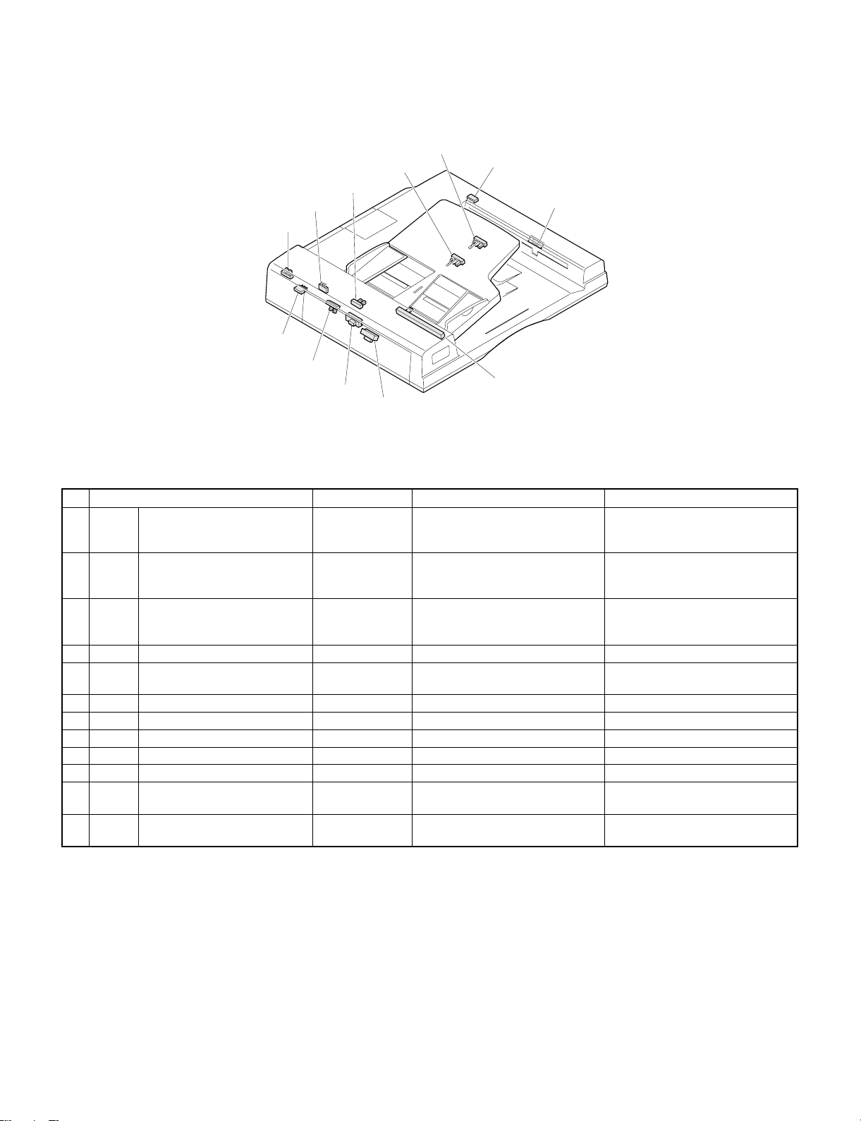
No. Name Function
1.APHPS2
2.DPPD1
3.APHPS1
4.DPPD25.DTPID 6.DPFD
7.PAM2 8.PAM1 9.DPFC 10.DRRC
11.DDC
12.ADUPWB
18 ICU PWB Image process control
19 Laser drive PWB Laser beam drive
20 LCD control PWB LCD display control
21 LCD inverter PWB LCD backlight lighting
22 LCD volume PWB LCD display density control
23 Manual feed tray paper size sensor PWB Manual feed tray paper size detection
24 Mother PWB ICU PWB, printer PWB interface
25 Operation control PWB Operation panel control
26 PCU PWB Process control
27 Polygon motor drive PWB Polygon motor drive
28 Process control volume PWB Bias voltage adjustment
29 Interface PWB Interface when connected with a personal computer Option
30 Printer PWB Used when the machine is used as a printer of the connected computer. Option
9. Duplex copy tray
Signal
name
1 APHPS2 ADU rear plate home position sensor Low when at home position Transmissive photosensor
2 DPPD1 ADU paper transport sensor-1 High when paper passes over Transmissive photosensor
3 APHPS1 ADU alignment plate home position sensor Low when over home position Transmissive photosensor
4 DPPD2 ADU paper transport sensor-2 High when paper detected Transmissive photosensor
5 DTPID ADU tray sensor High when paper detected Transmissive photosensor
6 DPFD ADU paper entry sensor High when paper detected Transmissive photosensor
7 PAM2 ADU rear plate motor ADU rear plate drive DC stepping motor
8 PAM1 ADU alignment plate motor ADU alignment plate drive DC stepping motor
9 DPFC ADU paper feed clutch ADU paper feed roller rotation Electromagnetic clutch
10 DRRC ADU counter roller clutch ADU counter roller rotation Electromagnetic clutch
11 DDC ADU drive clutch ADU drive Electromagnetic clutch
12 ADUPWB Diode PWB Duplex copy tray load driving
Name Output/Function Type
4 – 11
Page 24
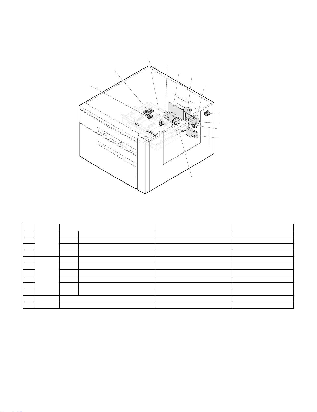
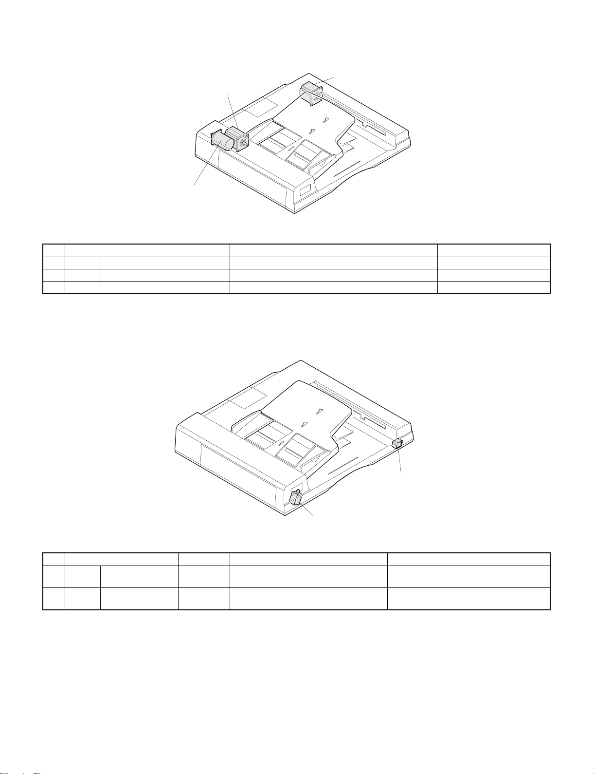
10. Desk unit (Major parts)
7.DPFS1
1.E1MOT
11.RCL
6.DPFC1
5.BCL
3.HMOT
4.LUM2
13.D es k mai n PWB
2.E2MOT
9.P1CL
12.Desk drive PWB
10.P2CL
No. Section Name Function Type
1 Motor E1MOT Paper tray 3 lift-up motor 1 Paper tray 3 lift-up DC motor
2 E2MOT Paper tray 3 lift-up motor 2 Paper tray 3 lift-up DC motor
3 HMOT Paper tray 3 transport motor Paper tray 3 paper transport DC brushless motor
4 LUM2 Paper tray 2 lift-up motor Paper tray 2 lift-up DC motor
5 Clutch
solenoid
6 DPFC1 Paper tray 2 pick-up clutch Paper tray 2 pick-up roller rotation Electromagnetic solenoid
7 DPFS1 Paper tray 2 pick-up solenoid Paper tray 2 pick-up roller pressing Electromagnetic solenoid
9 P1CL Paper tray 3 pick-up roller 1 clutch Paper tray 3 pick-up roller 1 clutch Electromagnetic clutch
10 P2CL Paper tray 3 pick-up roller 2 clutch Paper tray 3 pick-up roller 2 clutch Electromagnetic clutch
11 RCL Paper tray 3 resist clutch Paper tray 3 resist clutch Electromagnetic clutch
12 PWB Desk drive PWB Desk unit wiring interface
13 Desk main PWB Desk unit main control
BCL Paper tray 3 separation clutch Paper tray 3 separation roller rotation Electromagnetic clutch
4 – 12
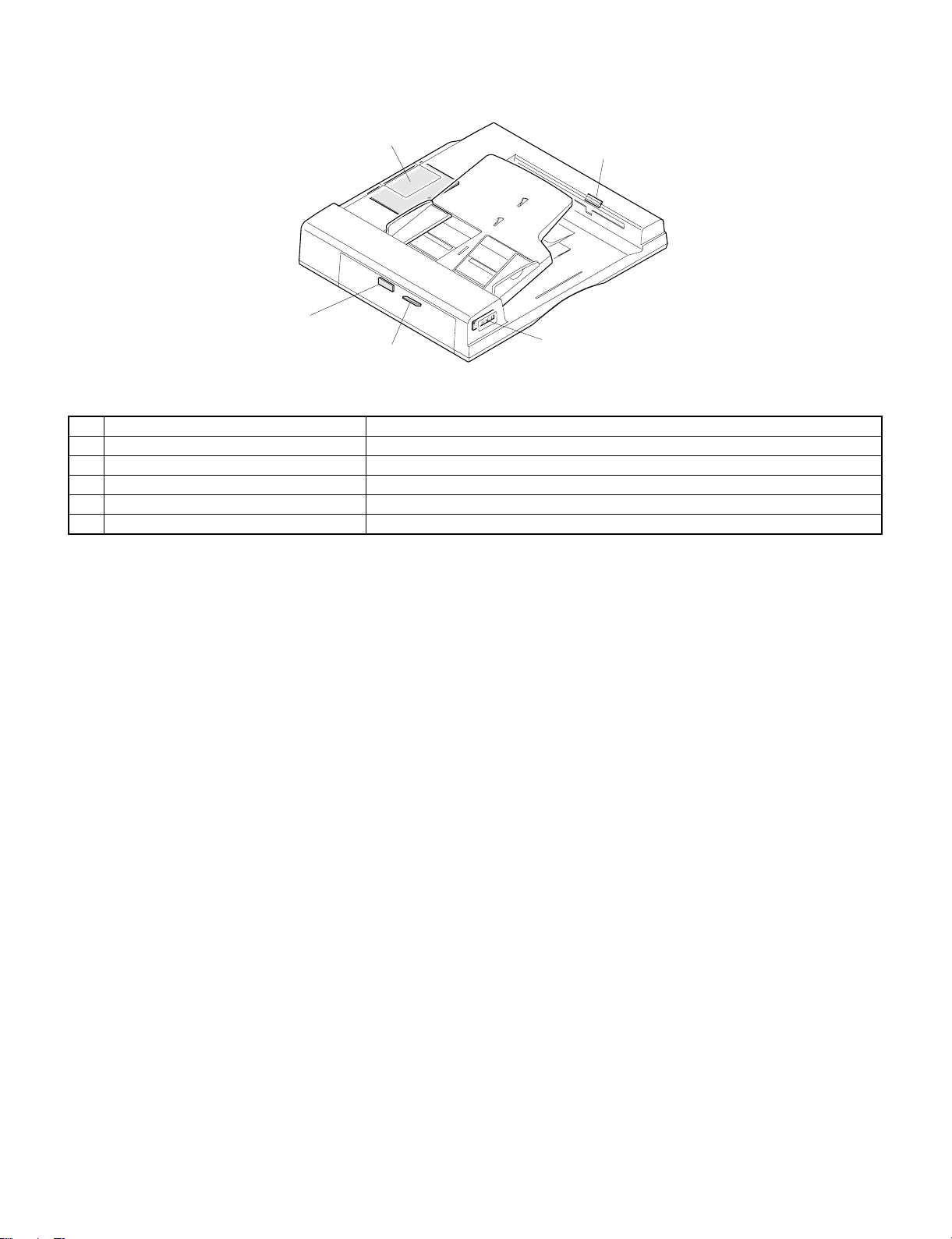
Page 25
11. Desk unit (Sensor)
19.SIZESW
7.DPE2
6.DLUD2
4.DLPD3
16.LMS2
3.DLPD2
11.DPTD2
13.E2CLK
15.LMS1
10.DPTD1
2.DLPD1
12.E1CLK
17.LUD3
18.PED3
8.DPOD1
9.DPOD2
5.DLUD1
14.F/LSW
1.DDO P
No. Section Name Function Type Contact/output
1 Desk
unit
2 DLPD1 Desk paper pass sensor 0 Paper transport detection 0 Reflection type sensor High when paper pass over
3 DLPD2 Paper tray 3 paper pass sensor1Paper transport detection 1 Reflection type sensor High when paper pass over
4 DLPD3 Paper tray 3 paper pass sensor2Paper transport detection 2 Reflection type sensor High when paper pass over
5 DLUD1 Paper tray 3 lift-up sensor 1 Paper tray 3 lift-up upper limit
6 DLUD2 Paper tray 3 lift-up sensor 2 Paper tray 3 lift-up upper limit
7 DPE2 Paper tray 3 paper empty
8 DPOD1 Desk unit resist sensor 1 Paper pass detection 1 Photo interrupter Low when paper is detected
9 DPOD2 Desk unit resist sensor 2 Paper pass detection 2 Photo interrupter Low when paper is detected
10 DPTD1 Paper tray 3 paper quantity
11 DPTD2 Paper tray 3 paper quantity
12 E1CLK Paper tray 3 lift-up motor 1
13 E2CLK Paper tray 3 lift-up motor 2
14 F/LSW Front loading open/close switch Paper tray 3 open/close
15 LMS1 Limit sensor 1 Prevention against excessive
16 LMS2 Limit sensor 2 Prevention against excessive
17 LUD3 Paper tray 2 lift-up sensor Paper tray 2 lift-up upper limit
18 PED3 Paper tray 2 paper empty
19 SIZESW Paper tray 3 paper size switch Paper tray 3 paper size setting Slide switch
DDOP Desk side open/close sensor Desk side door open/close Photo interrupter Low when desk side door is
open
Photo interrupter High when interrupted
detection
Photo interrupter High when interrupted
detection
sensor
sensor 1
sensor 2
encoder clock detector
encoder clock detector
sensor
Paper tray 3 paper empty
detection
Paper tray 3 paper quantity
detection
Paper tray 3 paper quantity
detection
Lift-up motor encoder clock
detection
Lift-up motor encoder clock
detection
detection
height of cassette paper
height of cassette paper
detection
Paper tray 2 paper empty
detection
Reflection type sensor High when paper is detected
Photo interrupter
Photo interrupter
Photo interrupter Pulse output
Photo interrupter Pulse output
Photo interrupter High when open
Photo interrupter High when interrupted
Photo interrupter High when interrupted
Photo interrupter Low when lift plate detected
Photo interrupter Low when paper is detected
4 – 13
Page 26
12. RADF (Sensor)
6.DLS1
4.DED
7.DSS
10.AUOD
8.DFMRS
11.FGOD
12.TGOD
3.RDD
9.DWS
1.DFD
5.DWVR
2.DTD
No. Name Type Function, operation Contact point, output
1 DFD Document feed sensor Reflection sensor Becomes H level when the leading
edge of document reaches the
resist roller.
2 DTD Document timing sensor Reflection sensor Becomes H level when the leading
edge of document reaches near the
transport belt.
3 RDD Reversion sensor Reflection sensor Becomes H level when the leading
edge of document is transported to
reversion/paper exit path.
4 DED Document end sensor Photo interrupter Detection of last paper in tray H level when document is detected.
5 DWVR Document width knob Slide knob Detection of document width on tray
(judged by resistance value)
6 DLS1 Document length sensor 1 Photo interrupter Detection of document length on tray H level when document is detected.
7 DSS Document setting sensor Photo interrupter Detection of document set on tray H level when document is detected.
8 DFMRS Paper feed motor rotation sensor Photo interrupter Detection of paper feed motor speed Pulse output
9 DWS Document width sensor Photo interrupter Detection of document width L level when document is detected.
10 AUOD ADF open/close switch Microswitch Detection of ADF unit operation L level when closed
11 FGOD Paper feed guide switch Microswitch Detection of paper feed guide
operation
12 TGOD Reflection guide switch Microswitch Detection of reversion cover
operation
H level when document is detected.
H level when document is detected.
H level when document is detected.
H level when document is detected.
L level when closed.
L level when closed.
4 – 14
Page 27
13. RADF (Motor)
3.DRM
2.DTM
1.DFM
No. Name Function, operation Type
1 DFM Paper feed motor Driving of pick-up roller, separation roller, and resist roller DC motor
2 DTM Transport motor Driving of transport belt roller Stepping motor
3 DRM Reversion motor Driving of reversion roller and paper exit roller Stepping motor
14. RADF (Clutches and solenoid)
2.DRSOL
1.DFSOL
No. Name Type Function, operation Contact point, output
1 DFSOL Paper feed solenoid DC solenoid Presses paper feed weight plate against
document to operate the shutter.
2 DRSOL Reversing solenoid DC solenoid Selects between paper exit and reversion
paths by driving reversing flapper.
Weight plate and shutter go down when
turned ON.
Reversion path is selected when turned ON.
4 – 15
Page 28
15. RADF (PWB)
1.Control PWB
2.Document f eed s enso r PW B
4.LE D PW B
3.Document timing sensor PWB
No. Name Function
1 Control PWB RADF control
2 Document feed sensor PWB Detection of document feed
3 Document timing sensor PWB Detection of document transport timing
4 LED PWB LED lighting
5 Reversing sensor PWB Detection of document reversing
5.Reversi ng sensor P WB
4 – 16
Page 29
[5] UNPACKING AND
INSTALLATION
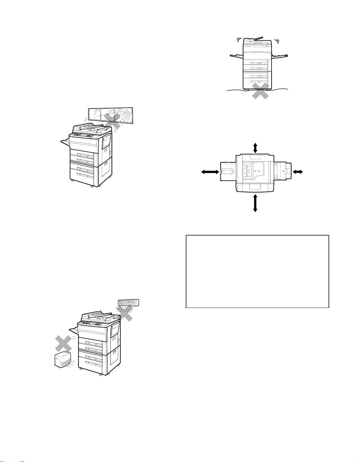
1. Use environment
To ensure safety and proper machine performance, please note the
following before initial installation and whenever the machine is to be
relocated.
(1) The copier should be installed near an accessible power outlet for
easy connection.
(4) Ensure that the area chosen for the machine location is level.
(5) Be sure to allow the required space around the machine for ser-
vicing and proper ventilation.
11-13/16"
(30 cm)
(2) Be sure to connect the power cord only to a power outlet that
meets the specified voltage and current requirements.
Also make certain the outlet is properly grounded.
The outlet must be kept apart from appliances that consume much
power, such as large motors.
(3) Do not install the machine where it is:
• damp or humid,
• exposed to direct sunlight,
• extremely dusty,
• poorly ventilated,
• subject to extreme temperature or humidity changes (e.g., near
an air conditioner or heater).
23-5/8"
(60 cm)
23-5/8"
(60 cm)
A small amount of ozone is produced within the copier during
operation.
The emission level is insufficient to cause any health hazard.
NOTE:
The present recommended long term exposure limit for ozone is
0.1 ppm (0.2 mg/m3) calculated as an 8 hr. time-weighted average
concentration.
However, since the small amount that is emitted may have an
objectionable odor, it is advisable to place the copier in a ventilated area.
11-13/16"
(30 cm)
5 – 1
Page 30
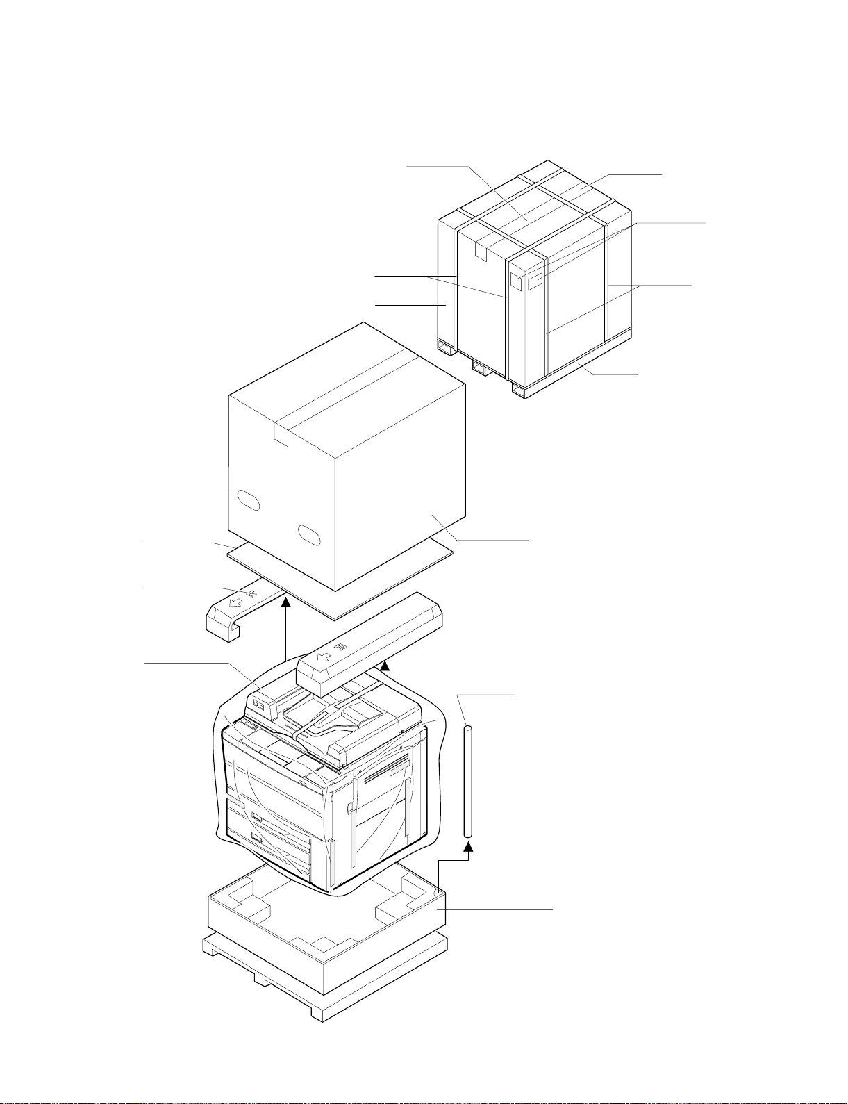
2. Unpacking
Craft tape
50 mm wide
PP band x 2
Stitcher x 4
Package box
indication label
PP band x 2
Skid UN
Upper reinforcing
material
Copier
Pack-AD (upper)
Support x 4
Bottom case assembly
PACK-CASE
PACK-CASE
(1) Package form drawing
The PPC unit and the desk unit are separately packaged.
Unpack the package in the following manner:
A. PPC section
a. Remove the PP band.
b. Remove the packing case.
c. Remove the inside pads and packaged items.
d. Remove the PPC unit.
5 – 2
Page 31

B. Desk unit
a. Cut the PP band.
b. Open the exterior box.
c. Remove the packaged items:
1) Remove the short spacer package assembly
2) Remove the screw package assembly A.
3) Remove the screw package assembly B.
4) Remove the instruction manual.
d. Remove the upper pad.
e. Remove the vinyl sheet.
f. Remove the desk unit.
Exterior box
Screw pa ckage assemb l y B
Taped to recession in the
upper pad
Screw package assembly A
Taped to re cession in the
upper pad
Lower pad
Instruc t io n Ma nu al
Short spacer package assembly
Taped to recession in upper pad
Upper pad
Copier vi nyl sheet
Desk unit
Bottom case
5 – 3
Page 32

3. Setting-up procedure
(1) Installing desk unit
A Place the copier on the desk
B Secure the copier to the desk
C Connect the desk relay harness
D Secure the desk on the floor
(2) Releasing optical system lock
(3) Setting fusing unit
A Removing fusing unit
B Pressurize heat roller
C Installing cleaning roller
(4) Cleaning charger roller
A Cleaning main charger unit
B Cleaning transfer/separation charger unit wire
(5) Installing RADF tray
A Connecting RADF tray connector
B Installing tray
(6) Setting developer unit
A Removing the developing unit
B Supplying the developer
C Adjusting toner density sensor level
D Checking process control sensor value
(7) Toner supply
(8) Setting up paper tray 1/2
(9) Setting up paper tray 3 (LCC tray)
A Paper size setting
B Adjust any center misalignment
(10) Checking copy density
(11) Installing sorter (SF-S53N) <option>
(12) Installing sorter (SF-S15) <option>
Included parts
Parts for use with the Deck unit
Mounting screws
(4 pcs.)
Parts for use with the SF-S53N
Caster spacers
(4 pcs.)
Caster mounti ng screws (M4 x 60)
(8 pcs.)
Be sure to unplug the copier before carrying out the
following procedures.
A. Place the copier on the desk.
Place the copier on the desk so that the feet of the copier fit into the
corresponding holes in the desk.
When doing this, be careful that the copier does not come to rest on
the paper guide or other parts of the desk that might be damaged by
the weight of the copier.
(1) Installing desk unit
Paper guide
B. Secure the copier to the desk.
Use the included four mounting screws to secure the copier to the
desk.
• In addition to securing the copier to the desk, these screws also
function to electrically ground the desk, so be sure to tighten all
mounting screws securely.
Left side
Copier
Right side
Copier
5 – 4
Mounting
screws
Desk
Desk
Mounting
screws
Page 33

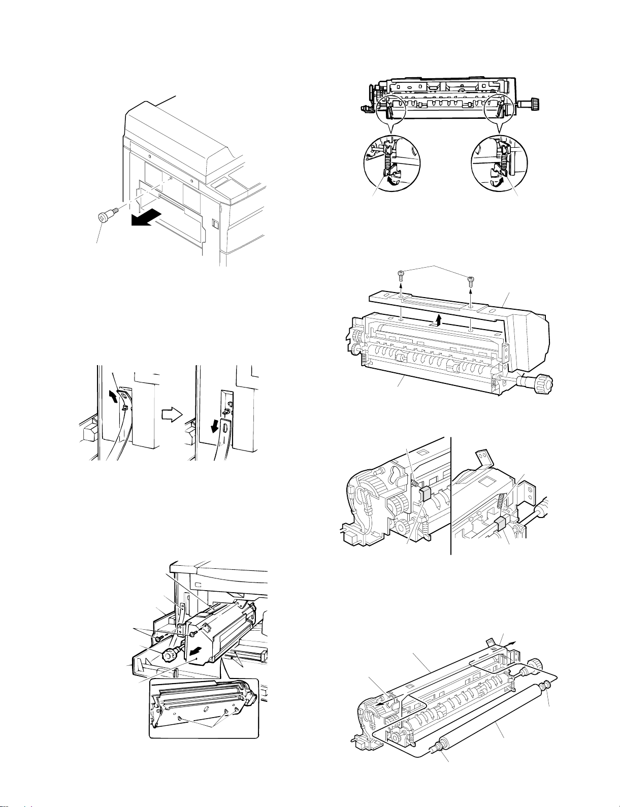
C. Connect the desk relay harness.
Mounting scr ew
Rear coverlet
Rear cabinet panel
Clamp
connector
a. Remove the rear coverlet of the copier.
Remove the mounting screw which holds the rear coverlet to the rear
cabinet panel, then remove the rear coverlet.
b. Connect the desk relay harness.
Remove the connector harness from the clamp which bundles the
desk relay harness together.
Next, remove the temporary connector which is attached to the connector of the desk relay harness, and connect the connector from the
copier into the connector on the desk.
* Note that the temporary connector will no longer be used.
c. Remount the rear coverlet of the copier.
Return the rear coverlet to its document position and use its mounting
screw to mount it.
Rear cabinet panel
Mounting scr ew
coverlet
D. Secure the desk on the floor.
Turn clockwise the two adjusters at the lower front of the desk to
lower them to the floor and secure the desk in place.
Use the caster lock levers on the front side (right and left) of the desk
to lock the casters in place.
Caster
Caster lock lever
Adjuster
Note:
Turning on the power with no desk connected causes the trouble
"U6-00," thereby disabling the machine operation.
5 – 5
Page 34
(2) Releasing optical system lock
Mirror unit fixing screw
Front cabinet band
Carrier strap
Front cabinet band
Paper exit area
Fixing screw
Roller rotation knob
Front cabinet
Fusi ng unit
Rib
Guide pin
Remove the 2nd/3rd mirror unit locks.
Remove the screws securing the 2nd/3rd mirrors on the left side of
the machine.
B. Pressuring heat roller
Move the pressuring levers at the front and rear sides of the fusing
unit as shown in the figure below. This applies pressure on the upper
and lower heat rollers.
(3) Setting fusing unit
A. Remove the fusing unit.
a. Lifting the paper exit knob, open the paper exit. Then, remove the
front cabinet band on the left side of the front cabinet.
Rear side
Pressing lever
Front side
Pressing lever
C. Installing cleaning roller
a. Remove the screw securing the fusing cover. Slide the fusing
cover toward you to remove it.
Fixing screw
Fusing cove r
Fusi ng unit
b. Remove the CL springs secured by tape onto the front and rear
sides of the fusing unit.
Rear side
CL spring
Front side
b. Remove the screw securing the fusing unit.
c. Holding the rotating knob of the fusing unit, remove the fusing unit
carefully pressing the front cabinet. At this time, use caution not to
let the guide pin at the bottom of the fusing unit contact the front
cabinet rib. Then, holding the carrier strap of the fusing unit,
remove the fusing unit.
CL sprin g
CL spring fixing tape
CL spring fixing tape
Note: Make sure to remove fixing tape carefully and thoroughly.
c. Pass the cleaning roller through the round hole in the rear side of
the fusing unit. Insert the cleaning roller through the front round
hole. Then, position the bearings of the cleaning rollers at both the
front side and the rear side.
Front side round hole
Fusing u nit
Rear side round hole
Bearing
Cleaning roller
Bearing
5 – 6
Page 35

d. Hook the CL spring on the front and rear frames of the fusing unit.
Rear side
CL spring
Front side
CL spring
Fixing screw
Fusing cov e r
Fusing unit
Front cabinet band
Paper exit area
Fixing angle
Fixing screw
Front cabinet
Fusing unit
Fixing angle
Positioning pin
Guide pin
Make sure that the CL spring presses the bearing as shown in the
figure below.
e. Reinstall the fusing cover which was removed in step a, and
secure it with screws.
(4) Cleaning the charger
A. Cleaning main charger unit electrode
a. Holding down the hook of the main charger unit, release the lock.
Pull out the main charger unit from the copier and remove it.
Main charger unit
b. Remove the screw securing the electrode to the rear side of the
main charger unit. Remove the electrode.
Fixing screw
Electrode
f. Place the guide pin at the bottom of the fusing unit in the groove
of the copier. Holding down the front cabinet, push in the fusing
unit slowly as far as possible.
At this time, make sure the positioning pin of the copier frame is
securely installed in the positioning hole in the fusing unit fixing
angle. Secure with the fixing screws which were removed in step
(3) A. b., and close the paper exit unit. Reinstall the front cabinet
band which was removed in step (3). A. a. Close the paper exit
unit.
Main charger unit
c. Stick the electrode cleaner to the tips of the electrode for cleaning
two or three times.
Electrode cleaner
Electrode
Note: • Do not move the cleaner with the electrode tips stuck
into the cleaner.
• Cleaning should be evenly on the whole area, but not
partly.
d. Install the electrode on the document position and secure with the
screw.
e. Slide the main charger unit along the copier guide securely to
stop.
Main charger unit
5 – 7
Page 36

B. Cleaning transfer/separation charger unit wire
Transport opening/closing lever
TC loc k plat e
Transfer/separation
charger unit
Transport opening/closing
lever
Separation charger guide
Charger case
A
Charger cleaner
Charge r wir e
a. Bring the transport opening/closing lever down to the left. Turn the
TC lock plate clockwise with a scale or a slotted screwdriver to
release the TC lock. Remove the transfer/separation charger unit
from the copier.
d. Install the separation charger guide on the charger case. Insert
the transfer charger unit, along the groove in the guide, all the way
to stop. Turn the TC lock plate counterclockwise to lock. Back off
the transport unit opening/closing lever clockwise to close the front
cabinet.
b. Remove the part A of the separation charger guide and slide the
guide in the direction indicated by the arrow, to remove the
separation charger guide from the charger case.
c. Clamp the transfer/separation charger wire with the charger
cleaner, and clean the wire by moving the cleaner in the direction
indicated by the arrow.
Transport opening/closing lever
Transport opening/closing
lever
TC lock plate
Transfer/separation
charger unit
(5) Installing RADF tray
A. Connect RADF tray connector
a. Temporarily install the tray fixing screws to connect the RADF
connector to the tray connector.
Tray side connector
Tray fixing
screw
ADF side connector
B. Installing tray
a. Install the tray as shown in the figure below, and secure with the
screws.
Tray fixing
screw
Tray
5 – 8
Page 37

(6) Setting up developer unit
Toner box lever
Developi n g unit loc k lev e rToner box lever
Developing unit lock lever
Carry strap
A. Removing the developing unit.
a. Open the front cabinet.
b. Tilt down the toner box lever and pull out the toner box until it
stops.
B. Supplying developer
a. Remove the connector which is connecting the toner hopper and
the developing unit.
Remove the five toner hopper fixing screws, the developing unit,
and remove the toner hopper.
c. Slide the developing unit lock lever in the arrow direction to
release lock, and hold the toner box lever and pull out the
developing unit until it stops.
[Note]
• When lock is released and the developing unit becomes free to
move, let go of the developing unit lock lever.
Fixing screw (silver)
Fixing screws (silv er )
Ton e r hopp er
Fixing screws (blue)
Developing unit
Fixing screw
(blue)
connector
b. While supplying developer from the developer supply port of the
developing unit, turn the MG gear clockwise with a screwdriver (+)
or a scale to completely supply developer into the developing unit.
Develo pe r
Developer s uppl y port
d. Hold the carry strap of the developing unit and slide the develop-
ing unit lock lever in the arrow direction to release lock. Then
remove the developing unit.
Deve loping unit
MG gear
c. Install the toner hopper to the developing unit, and fix it with the
five screws. Connect the 5P connector of the developing unit with
the toner hopper.
Fixing screw (silver)
Fixing screw (silver)
Ton e r hopp er
Fixing screw (blue)
Developing unit
Fixing screw
(blue)
5P connector
Note: If the hopper and the five screws are not securely fixed,
toner may flow into the developing unit when supplying
toner.
5 – 9
Page 38

C. Adjusting toner density sensor level
C 0 / 5
2
2
Toner box lever
Turn ON the power supply switch of the copier.
Note: Make sure the main charger unit is securely inserted, before
executing simulation 25-1 or 25-2.
a. Carry out the following key operation for the simulation 25-2.
b. The simulation 25-2 is finished in 3 minutes.
Note: Do not cancel the simulation during execution, because
automatic reading cannot be performed.
c. Cancel the simulation 25 with the CA key.
Note: The simulation 25-2 should be performed whenever the
developer is replaced with a new one. The developing adjustment value for servicing should be checked by executing the Sim 25-1. (If the Sim 25-2 is used for this purpose,
toner density trouble might occur.)
D. Checking process control sensor value
Execute Sim44-2 and Sim44-3, to make sure that the results are
within a range of 210 ±30. If any of the results are out of the range,
adjust, referring to the procedure described under "Image Adjustment."
d. Install the toner cartridge to the toner box as shown in the figure
below.
e. Move the toner cartridge in the arrow direction until it stops.
(7) Toner supply
A. Toner supply
a. Open the front cabinet.
b. Tilt down the toner box lever towards you and pull out the toner
box until it stops.
c. Shake the toner cartridge up and down about 5 times.
f. While holding the toner cartridge, pull the seal to supply toner.
[Note]
• It takes about 30 seconds to finish supplying toner.
g. Tap the top of the toner cartridge to put down toner attached
inside the toner cartridge.
Note: Though the cartridge look like that of the SF-2025/2030/
2040, its cap pawl shape and position are different and the
color of the cap slide section is brown for identification.
5 – 10
Page 39

h. Move the empty toner cartridge in the arrow direction to remove.
Toner box lever
Pa ck age fi xi ng scr e w
Package fixing screw
b. Changing the side plates F and R sizes (factory set for A/3 or
double letter size)
Install the side plates F and R on the tray, along with the mark-
ings, so that they form the paper size you want. Secure them with
screws.
i. Push the toner box slowly to the document position, and lift the
toner box lever.
Toner supply is completed with the above procedure. Close the front
cabinet.
Side plate R
Fixing screw
Side plate F
Fixing screw
c. Changing rear end plate position
Remove the rear end plate and reinstall it at the position which the
paper size you want is created.
Rear end plate
(8) Setting up paper tray 1/2
a. Removing the tray package fixing screws.
Remove the package fixing screws securing the paper pressing
plate in the tray.
d. Setting size detection spacer
Install the size detection spacer in an appropriate position so that
your desired paper size is created.
Size det e ction sp acer
(Example) A3 setting
5 – 11
Page 40

e. Changing paper size indication plate
A3
A4R
B4
B5
A4
B5R
A5
Size detection spacer setting
Dummy
slot
W Lett er
Legal
Letter R
Letter
Invoice
Paper siz e indi cat ion plate
Indication line label
Install the paper size indication plate so that the name of the
paper size you preset can be seen through the paper size indication window.
Note: Remember that the paper size indication plate carries
paper size names on its both face and back sides.
f. Setting paper
Set less than the specified amount of sheets of paper in the tray.
Push in the tray into the copier as far as possible.
5 – 12
Page 41

(9) Setting up paper tray 3
A. Paper size setting
a. Pull out the cassette.
Grasp the cassette by the handle and pull it out gently as far as it will
go.
b. Adjust the front and rear paper guides.
Remove the mounting screws holding the front and rear paper guides
(one screw per guide) in place.
Insert the tabs (two on the bottom of each paper guide) into the
cassette in the notches corresponding to the desired paper size.
Next, use the mounting screws to secure the top of the front and rear
paper guides (one screw per guide) in the positions corresponding to
the desired paper size.
Mounting screws
[example\ A4 setting
A4
Front pap er gu i de
LT
B5
c. Adjust the side guides
Remove the mounting screws (one per guide) holding the right and
left paper side guides in place.
Use the mounting screws to secure the right and left paper size
guides (one screw per guide) in the positions corresponding to the
paper size which has been set.
Mounting scr ew
Right paper side guide
Left paper side guide
Mounting screw
Where to set th e moun t ing scr ew for vari o us p aper si zes
A4 B5
A4
LT
B5
LT
B5
LT
A4
[example\ A4 setting
Rear paper guide (fron t p ape r gui d e)
Rear paper guide
Tab
Tab
5 – 13
Page 42

d. Set the paper size switch
Set the paper size switch to match the paper size which has been
set.
Paper size switch
LT
A4
B5
f. Place the paper in the cassette.
Place paper in the right paper cassette.When doing this, do not stack
the paper higher than the maximum height line indicated on the cassette.
Next, place paper in the left paper cassette.When doing this, do not
stack the paper higher than the maximum height line indicated on the
cassette.
e. Change the paper size indicator.
Remove the paper size indicator and re-insert it so that the paper size
for which the cassette has been set is visible in the paper size indication window.
Note that paper size indications are printed on both sides of the paper
size indicator.
Paper size indicator
Grasp the cassette by the handle and gently push it all the way into
the desk as far as it will go.
Plug the copier into a grounded outlet and turn the power switch on.
Then, follow the procedure below.
5 – 14
Page 43

B. Adjust any center misalignment.
Center adjuster
Direction A
Direction B
Center adjuster mounti ng screws
No adjustment should be needed for the unit as it is factory-set.
However, if it is off-center, adjust it according to the following procedure.
Make a copy. If it is off center as shown in fig. 1 or fig. 2, loosen the
two center adjuster mounting screws attached to the cassette and
adjust it following the prcedure below.
(10) Copy density check
After installing the copier, check the copy density. If the density is not
in the specified range, adjust it.
(Refer to the print quality adjustment.)
(11) Installing sorter (SF-S53N)
<option>
Included par ts
[Note]
When mounting the center adjuster, make sure that the mounting
screws are positioned in the same spot in their respective slots.
When off center as shown in fig. 1
Move the center adjuster in direction A and secure it with the two
mounting screws. Make a copy to check whether it is centered
properly.
Fig. 1
Center line of the first copy image
Paper center line
Caster screws
(M4 x 60): 8
Sorter mount ing pla te screw s
(M4 x 12): 2
Bracket screws
(M4 x 10): 2
Rail: 1
Rail screws A
(M4 x 6): 2
Rail screws B
(M4 x 6): 1
Rail mounting plate screws
(M4 x 14): 2
Caster spacers: 4
When off center as shown in fig. 2
Move the center adjuster in direction B and secure it with the two
mounting screws. Make a copy to check whether it is centered proerly.
Fig. 2
Center line of the first copy image
Paper center line
Sorter mounting plate: 1
Rail mounting plate: 1
5 – 15
Page 44
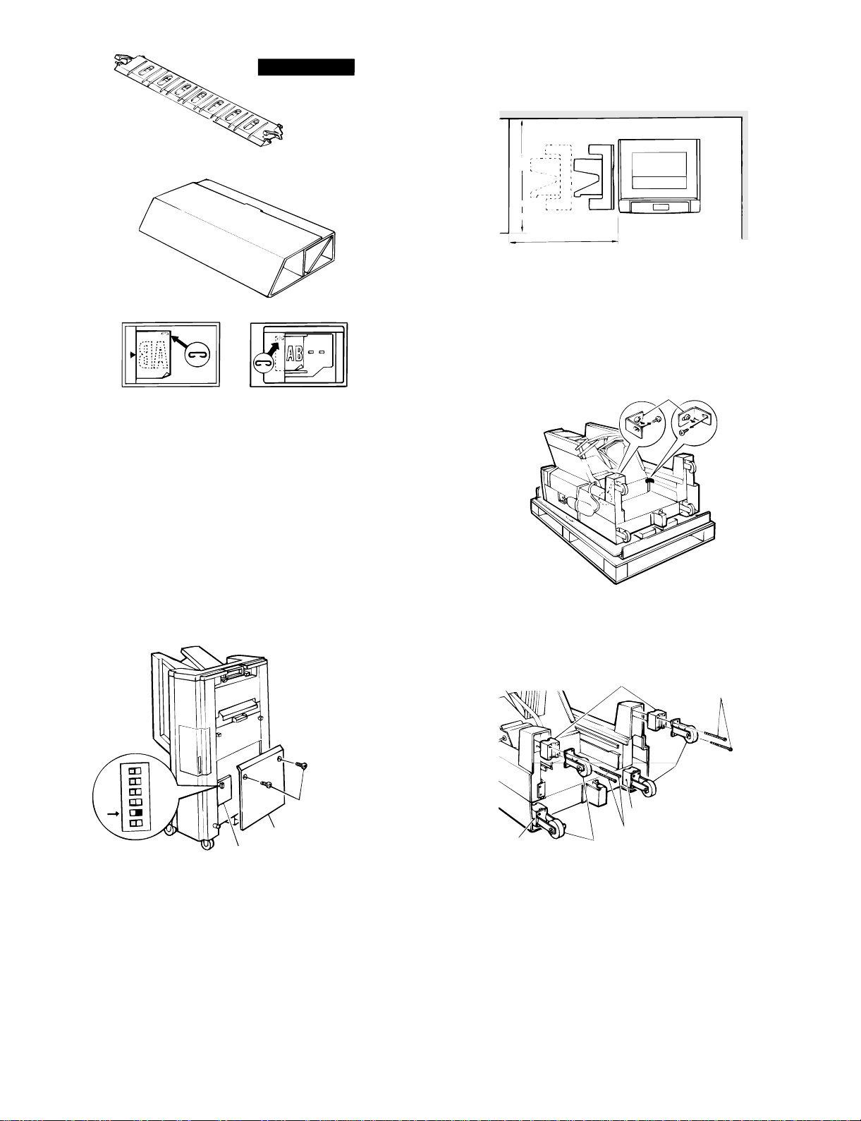
Support gui de: 1
Sorter protection mat: 1
Be sure that you have plenty of room around the
copier for work space.
Green label: 1
1.5m
1.0m
Remove the securing fixtures and attach the caster
spacers.
★ When performed on the skid.
Remove the securing fixtures (2).
Stapli ng l oc at ion labe l A: 1 Stapling loc ation labe l D: 1
In addition, the saper is required which is packed together with the
desk.
Before installing
Before installing to copier model, turn the DIP
switches to "ON".
Remove the 2 mounting screws securing the sorter control cover,
then remove the sorter control cover.
Next, move dip switch number 5 to the "ON" position (the dip
switches are attached to the sorter controller circuit board).
Reattach the sorter controller cover in its document position and
secure it with the 2 mounting screws.
ON
1
2
3
4
5
6
Dip switches
Sorter control circuit board
Mounting screws
Sorter control cover
Securing fi xt ures
Remove the caster screws (2 per caster) and take off the 4 casters.
Next, attach the casters and caster spacers using 2 screws each (M4
x 50) as shown in the figure.
Caster spacer s
Caster screws
Casters
Caster spacer
Caster screws
Caster spacer
Casters
5 – 16
Page 45

★ When not performed on the skid
Open the sorter protection mat, as shown in the figure, and position it
against the sorter’s casters. Lay the sorter down on the protection
mat.
Next, remove the securing fixtures (2).
Securing fixtures
Sorter protect i on mat
Unplug the copier’s power cord before carrying out
the following procedure.
A. Mounting of the staple sorter onto the copier.
1. Attach the sorter mounting plate.
Remove the screws (2) from the copier’s upper left cabinet panel.
Attach the sorter mounting plate with the 2 sorter mounting plate
screws (M4 × 12).
The sorter mounting plate screw holes are elongated; tighten the
screws so that the sorter mounting plate hangs down in its lowest
position.
Upper left ca bi net pa nel sc rew s
3
2
1
2
Remove the caster screws (2 per caster) and take off the 4 casters.
Next, attach the casters and caster spacers using 2 screws each (M4
x 50) as shown in the figure.
Caster spacer s
Caster spacer
Caster screws
CastersCaster spacer
Caster screws
Casters
Sorter mounting
plate screws
Sorter mounting
plate
2. Attach the support guide.
Attach the support guide by attaching its pawls (2 locations) to the
inside of the copier’s paper output section.
Pawls
Support gui de
3. Cut off the cut portions of the desk’s left cabinet
panel.
Cut off the 2 cut portions of the desk’s left cabinet panel.
Remove all the securing tape ( ) and securing
materials ( ) shown in the figures below.
Cut port i ons
Desk
5 – 17
Page 46
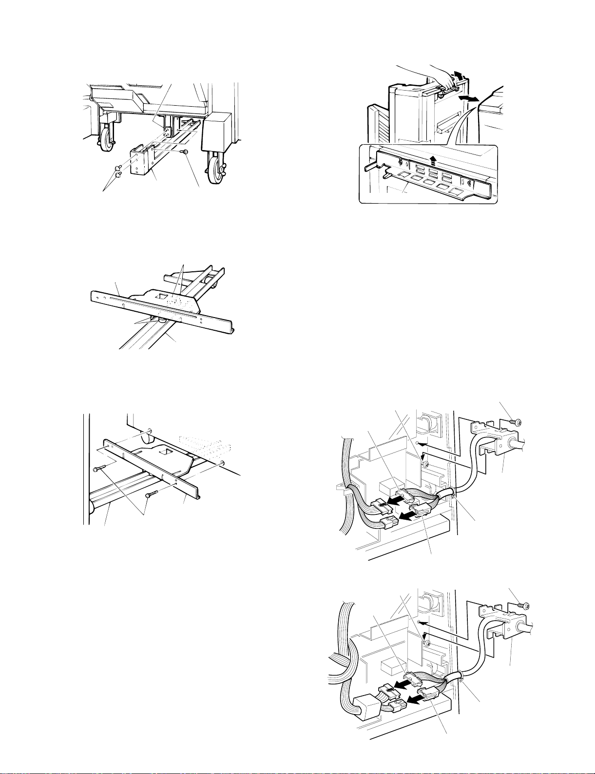
4. Attach the rail to the sorter.
Insert the rail into the rail mounting anchor, on the bottom of the
sorter, and attach them with the 2 rail screws A (M4 x 6) and 1 rail
screw B (M4 x 6).
Rail mounting anchor
2 Confirm that the staple sorter locks into place beside the copier.
If not, adjust the height of the sorter mounting plate until the staple
sorter locks securely into place.
Rail
Rail screws A
Rail screws B
5. Fit the rail mounting plate onto the rail.
Insert the rail between the rollers on the rail mounting plate as shown
in the figure.
Rollers
Rail mounting plate
Rollers
Rail
6. Attach the rail mounting plate to the copier desk.
Slide the rail, which was just attached to the sorter, under the copier
as shown in the figure. Attach the rail mounting plate to the copier
with the 2 rail mounting plate screws (M4 x 14).
Desk
Sorter mounting plate
8. Remove the copier’s rear cabinet panel and cut
off the cut portion of the left cabinet.
Remove the screws securing the copier’s rear cabinet panel and take
the panel off.
Next, cut off the cut portion (1 location) of the left cabinet panel.
9. Attach the sorter connectors.
Loosely screw in one of the two supplied bracket screws in the position shown in the figure.
Hook the bottom of the bracket in place over this screw, then insert
the other screw into the top of the bracket and tighten both screws
securely.
Connect the sorter’s 6-pin and 10-pin connectors to the copier’s 6-pin
and 10-pin connectors. Then insert the clasp of the tie band into the
hole on the bottom of the mounting plate for the circuit board.
Bracket
screws
6-pin
connector
Bracket screws
Rail mounting plate
Rail mo untin g p late sc r ews
Rail
7. Confirm that the staple sorter can be attached
and detached correctly.
1 Latch and unlatch the staple sorter from the copier to confirm that
it moves smoothly.
5 – 18
Bracket
screws
6-pin
connec tor
Bracket
Tie band
10-pin conn ec tor
Bracket screws
Bracket
Tie band
10-pin co nnec tor
Page 47

10. Reattach the rear cabinet panel.
Reattach the rear cabinet panel in its document position with the
mounting screws.
11. Affix the stapling location labels.
Affix the stapling location labels to the copier and RADF as shown in
the figure.
★ Copier
13. Set the mode.
• Perform the following key operations on the copier to set the
mode.
C
0 /
Performing the above operation will cause the current setting to
be displayed.
0 / 6
1
2
• The copier is equipped with the desk and RADF as standard. If an
optional sorter is installed, set to "15".
★ RADF
12. Affix the green label.
Lifting up on the staple sorter’s release lever, separate the sorter from
the copier.
Next, affix the green label to the paper output section handle as
shown in the figure.
Holding the staple sorter’s release lever, return the sorter to its document position. At this time, confirm that the staple sorter locks securely into place beside the copier.
Green label
1
5
B. Staple sorter operation check
1. Check the sort mode.
Make 20 copies in the sort mode and confirm that the copies are
distributed to the sort bins with no abnormal noises from the sorter.
2. Check the non-sort mode.
Make copies in the non-sort mode and confirm that they are sent to
the non-sort bin.
3. Use the RADF and check the staple sort mode.
Place 2 or more sheets in the ADF and make copies in the staple sort
mode. Confirm that the copies are distributed to the sort bins, that the
staple guide bar arranges the copies and that the stapler functions
properly.
If at this time the copies have not been stapled or the stapler is
jammed, adjust the staples by performing one of the following procedures.
If copies have not been stapled
1. Remove the staple cartridge.
Open the stapler cover, lift up on the staple cartridge and remove it
by pulling in the direction of the arrow.
Staple sorter
Paper output section handle
Plug the copier’s power cord into an electric outlet,
switch on the power, and then perform the
following procedure.
Staple cartridge
Stapler cover
5 – 19
Page 48

2. Check the staple cartridge.
Confirm that the sheets of staples in the cartridge are properly stacked.
If not, slide the staples back in the direction of the arrow while pressing in gently on the bottom of the cartridge.
3. Reinsert the staple cartridge.
Push the staple cartridge in horizontally until it clicks securely into
place.
Then close the stapler cover.
1. Remove the stapler unit.
Open the stapler cover and remove the mounting screw securing the
unit in place.
Next, remove the staple unit.
2. Open the stapling section.
Open the stapling section by pushing up on the stapling plate while
pressing on the stapling section release lever.
Stapling s ecti on rel ease l ev er
Stapling plate
Staple cartridge
Stapler c over
4. Confirm that papers are stapled correctly.
Place a set of papers in the 2nd bin (below the non-sort bin), check
the stapling location, and then press the manual staple key when it
lights up.
Next, remove the papers that were placed in the 2nd bin and confirm
that they have been stapled correctly.
At this time, if the papers still have not been stapled, repeat this
procedure once again.
Copy papers
Stapling l ocation
Copy papers
Copier
3. Remove the jammed staples.
Remove the jammed staples with the supplied tool as shown in the
figure.
* This tool can be found on the inside of the staple unit cover.
Tool
4. Close the stapling section.
Press down on the stapling plate and return it to its document position.
Next, return the stapling section release lever to its document position.
Stapling plate
This completes the staple sorter installation.
If staples have become jammed.
Stapling section
release lever
5 – 20
Page 49

5. Reinstall the staple unit.
Reinstall the staple unit in its document location using the mounting
screw to secure it in place.
Then close the stapler cover.
Staple unit
(12) Install a sorter. (SF-S15)
<Option>
Staple cover
Mounting s c rew
6. Confirm that papers are stapled correctly.
Place a set of papers in the 2nd bin (below the non-sort bin), check
the stapling location, and then press the manual staple key when it
lights up.
Next, remove the papers that were placed in the 2nd bin and confirm
that they have been stapled correctly.
At this time, if the papers still have not been stapled, repeat this
procedure once again.
Copy papers
Stapl ing location
Copy papers
Copier
SF-S15
Parts list
Support guide
Sorter se at
Sorter seat mounting
fixture (1 pc.)
Sorter seat mounting
screws A (2 pcs.)
Sorter seat mounting
screws B (1 pc.)
Bracket mounting
screws B (2 pcs.)
Unplug the copier and follow the procedure below.
1. Install the support guide.
Hook the pawls (two locations) of the support guide to the inside of
the copier paper exit end to install the guide as shown in Fig.
This completes the staple sorter installation.
Support guide
5 – 21
Page 50

2. Mount the sorter seat to the desk.
Remove the two cut-outs in the cabinet panel on the left side of the
desk.
Secure the two sorter seat mounting screws A to the desk.
Next, hook the sorter seat onto the two sorter seat mounting screws
A which were secured to the desk, and then use the one sorter seat
mounting screw B to secure the sorter seat mounting fixiture as
shown.
4. Place the sorter on the sorter seat.
While holding the handle, place the sorter on the sorter seat’s guide
rails and push it gently as far back as it will go.
When doing this, confirm that the rollers at the front of the sorter are
correctly seated on the sorter seat.
Rear
Guide rail
Guide ro ller
Guide rail
Guide ro ll er
Front
Sorter seat mounting
Cut-out
Sorter seat mounting
fixture
Sorter seat
screws A
Cut-out
Desk
Sorter seat mounting
screw B
3. Remove the front panel of the sorter.
Loosen the four mounting screws in the front panel of the sorter and
remove the panel.
Mounting
screws
Front panel
of sorter
Sorter
Sorter
Sorter seat
Handle
Sorter seat
5. Remove the rear cabinet panel from the copier
and cut out the notch in the cabinet panel.
Remove the four screws which secure the rear cabinet panel of the
copier to remove the rear cabinet panel.
Cut out the notch (one location) in the cabinet panel.
Mounting
screws
5 – 22
Page 51

6. Connect the sorter connectors.
10-pin connec tor
Tie band
Bracket
Bracket screws
Bracket
screws
6-pin
connect or
Bracket screws
Bracket
10-pin connector
6-pin
connector
Tie band
Bracket
screws
Use the two bracket mounting screws to secure the bracket attached
to the sorter harness to the frame of the copier.
Connect the 6-pin and 10-pin sorter connectors to the 6-pin and
10-pin connectors of the copier and insert the tie band into the hole
under the board installation part.
9. Adjust the clearance between the sorter and the
copier.
Push the sorter gently against the copier’s left cabinet panel. The
clearance spacers attached to the back of the sorter will determine
the standard clearance between the sorter and the copier. Turn the
adjustment knobs on the sorter seat to adjust the clearance so that
the spacers are touching the copier.
After adjusting the clearance, remove the clearance spacers.
Adjustment knobs
Sorter seat
7. Reattach the rear cabinet panel.
Use the four mounting screws to reattach the rear cabinet panel
removed in step (4) in its document position.
Clearance spacers
Standard
clearance
Clearance
spacers
10. Set the mode.
• Operate the keys on the copier to set the mode.
C 0 /
0 /
1
2
6
• The copier is equipped with the desk and RADF as standard. If an
optional sorter is installed, set to "15".
READY
51
8. Reattach the front panel of the sorter.
Use the four mounting screws to reattach the front panel of the sorter
removed in step (3) in its document position.
Mounting
screws
Mounting
screws
Front pan el
of sorter
5 – 23
Page 52

[6] PICTURE QUALITY
VR1
VR2
ADJUSTMENT
1. Initial setting of process control
Whenever the OPC drum or the process control PWB is replaced or
the sensor is cleaned or replaced, or before the picture density is
adjusted, check and if necessary adjust the process control initial
setting.
(1) Adjusting drum marking sensor output
1 Open the front door.
2 Remove the process cover on the drum cleaner unit.
(2) Adjusting process control sensor (picture
density sensor) output
1 Execute SIM 44-3.
The OPC rotates and the drum marking sensor output adjustment
value appears on the panel.
SIMULATION NO.44-3
ID SENSOR ADJUSTMENT
SENSOR RESPONSE:XXX
[PAUSE]KEY:END DISPLAY
2 Check to see if the output adjustment value displayed on the
panel is 210 ±30. If the value is not within the specified range,
adjust to the specified range with the VR-2 on the process control
PWB.
VR2
VR1
3 Execute SIM 44-2.
The OPC drum rotates and the drum marking sensor output adjustment value appears on the panel.
SIMULATION NO.44-2
DM SENSOR ADJUSTMENT
SENSOR RESPONSE:XXX
[PAUSE]KEY:END DISPLAY
4 Check to see if the output adjustment value displayed on the
panel is 210 ±30. If the value is not within the specified range,
adjust to the specified range with the VR-1 on the process control
PWB.
3 Reinstall the process cover.
4 Close the front door.
(3) Initializing OPC drum film wear correction
counter
The OPC drum rotating time counter counts up for every 20,000
seconds, correcting both the grid voltage and the laser power accordingly. (This operation should be performed only when the OPC drum
has been replaced.)
1 Execute SIM 24-7.
The panel appears like this.
SIMULATION NO.24-7
DRUM ADJUSTMENT TIME
WOULD YOU MIND IF CLEARING EXECUTE?
1. EXECUTE 2. CANCEL
SELECT WITH TEN KEY
2 Press the "1" key on the numeric keypad.
(4) Setting process control (picture density)
standard value
1 Execute SIM 44-4.
The LCD panel appears like this.
SIMULATION NO.44-4
PROCESS CONTROL INITIAL DENSITY SETUP
INITIAL DENSITY[XXX]:XXX
(0~255)
INPUT SETUP VALUE AND PRESS PRINT SW
2 Press the copy button. Make sure the standard value is 25. If the
value is not 25, adjust to 25 with the numeric keypad and press
the copy button.
3 Release the simulation mode.
6 – 1
Page 53

2. Picture quali ty adj ust m ent proced ur e
(1) Shading correction
Whenever any of the following services is performed, it is necessary
to set the shading white board correction value (SIM 63-2).
• Replacement of the copy lamp, copy lamp unit, CCD lens unit, the
2nd and 3rd mirror holder unit, or winding drive gear.
• Replacement or tension adjustment of the MB wire.
• Positional adjustment of the MB-B rail.
• When there occurs in the density of a half-tone area due to shad-
ing.
Before setting the shading whiteboard correction value, make sure:
• Each of the 1st to 3rd mirrors is free from dust or contamination.
• The standard whiteboard is clean.
• The table glass is free from dust or contamination.
• The A3 or W letter size paper to be placed on the document table
is free from contamination, folds, or wrinkles.
Setting procedure:
1 Lay 10 sheets of A3 or W letter size paper one on top of another
on the document table, as shown in the illustration below. (Do not
use recycled paper or color paper.) Use the white paper specified
by Sharp.
Points to be kept in mind when carrying out shading correction
• Lay A3 or W letter size paper, aligning their edges with the rear
edge of the table glass and the OR guide L alignment position.
(See the illustration.)
• When executing a simulation, do not hold down the A3 or W
letter size paper with the RADF.
• To securely hold in place, lay 2 copies of the Instruction Manual
on the sheets of A3 or W letter size paper to prevent them from
lifting.
2 Execute SIM 63-2.
SIMULATION No.63-2
SHADING WHITE BOARD CORRECTION
WITH A WHITE PAPER ON THE ORIGINAL
TABLE,TURN ON THE PRINT SWITCH.
PRINT SWITCH:EXECUTE SIMULATION
SIMULATION No.63-2
SHADING WHITE BOARD CORRECTION
CORRECTION VALUE IS SETTING.
[PAUSE]KEY:SUSPENDED ACTIVATION
SIMULATION No.63-2
SHADING WHITE BOARD CORRECTION
CORRECTION IS COMPLETED.
CORRECTION VALUE:XXX
[PAUSE]KEY:END DISPLAY
About 1 ∼ 4 min.
(2) Setting test chart
1 Lay a test chart (UKOG-0162FCZZ) on the document table at the
front frame side.
2 Lay 4 to 5 sheets of white paper (specified by Sharp), more than
120 mm wide and about 420 mm long, one on top of another on
the test chart, aligning their centers.
OR guide L
Align w i th t he ed ge of tabl e gl as s
Size of two copies of the attached
instruction manual
Align
A3/W letter
size paper
(100)
A3/W letter size paper
(50)
A3/W letter size paper
Align
Table glass
Area that can be
recognized by SIM63
UKOG-0162FCZZ
1
2
345
Test chart comparison table
UKOG-0162FCZZ
DENSITY No.
UKOG-0089CSZZ
DENSITY No.
KODAK GRAY
SCALE
12345678910W
0.1 0.2 0.3 0.5 1.9 0
123419A
67
8
SHARP CORPORATION
10 W
9
MADE IN JAPAN
6 – 2
Page 54

(3) Adjusting copy density
Execute SIM 46-01. After warming up, the ready lamp comes on and
at the same time, the current exposure level is displayed on the
panel.
AE_3.0 [ XXX ]
N_3.0 [ XXX ]
P_3.0 [ XXX ]
SFTP_3.0 [ XXX ]
30~170
AE: Automatic mode
N: Manual mode
P: Photo mode
SFTP: Soft focus photo mode
The copy density mode can be selected by using the copy density
key. The value of current copy density mode is displayed in reverse
video in brackets.
A. Adjusting copy density in the manual/Photo/Soft
focus photo modes
Select the picture quality mode (ex. manual mode) in which you
1
want to adjust the copy density, with the copy density key.
AE_3.0 [ XXX ]
N_3.0 [ XXX ]
P_3.0 [ XXX ]
SFTP_3.0 [ XXX ]
30~170
2 Make a copy.
Make sure that the "4" of the Sharp test chart UKOG-0162FCZZ is
copied and the "3" is not copied.
(for the UKOG-0089CSZZ, the "0.3" should be copied and the
"0.2" not copied.)
When too light:
Increase the value displayed on the COPIES MADE display.
When too dark:
Decrease the value displayed on the COPIES MADE display.
4
3
Not copied
Copied
The val ue can be set i n th e r a nge of 30 ∼ 170. The greater the set
value is, the darker the density is.
3 Press the copy density key to select the mode to be adjusted next,
and perform the same adjustment procedures.
(When the above set value is entered with exposure 3, the other
exposure (density) set values are automatically set.
B. Auto mode copy density adjustment
1 Select the auto mode with the copy density key.
AE_3.0 [ XXX ]
N_3.0 [ XXX ]
P_3.0 [ XXX ]
SFTP_3.0 [ XXX ]
30~170
2 Make a copy.
Check that "4" of Sharp test chart (UKOG-0162FCZZ) is copied
and "3" is not copied.
("0.3" of UKOG-0089CSZZ is copied and "0.2" is not copied.)
5 62
When too bright:
Increase the set value displayed on the copy quantity display.
When too dark:
Decrease the set value displayed on the copy quantity display.
4
3
5 62
Not copied
Copied
The val ue can be set i n th e r a nge of 30 ∼ 170. The greater the set
value is, the darker the density is.
When the copy density is within the reference range, the image adjustment is completed.
Note 1: SIM 46-2 allows to set the exposure level adjustment value
in each mode individually. (Refer to the section of simulations.)
(4) Image mode selection
Each image mode has two image expressions, which can be selected
with SIM 26-27.
When SIM 26-27 is executed, the following display is shown to allow
selection of 1 and 2 for each image mode.
SIMULATION NO.26-27
IMAGE DENSITY MODE SETTING
AUTO [X]:_1.(PEN) 2.(ORG)
MANUAL [X]:_1.(PEN) 2.(ORG)
PHOTO [X]:_1.(PHOTO1) 2.(PHOTO2)
SOFT_P [X]:_1.(SOFT_P1) 2.(SOFT_P2)
[|]KEY:MOVE PRINT SW:EXECUTE
Here are the characteristics of picture quality in each mode. Use them
as a rough guide.
(All the settings of picture quality are factory set for 1.)
12
Auto
Manual
Photo Calmness Enhancement of contours
Soft focus
photo
The settings "1" and "2" can be selected according to the purpose.
Reproduction of
characters and fine lines
Enhancement of contours
Rough patterns
High gray scale level
Calmness
Reproduction of
characters
Fine patterns
High density
(5) Selecting gray scale level
In SIM 46-7, it is possible to set the gray scale level in each picture
quality mode.
Execute SIM 46-7. The gray scale level adjustment value for each
picture quality mode appears. (The setting in each mode is factory set
for 10.)
SIMULATION NO.46-7
TONE ADJUSTMENT SETTING (COPY)
AUTO AE_3.0 (1~20) [XX]:XX
MANUAL N_3.0 (1~20) [XX]:XX
PHOTO P1_3.0 (1~20) [XX]:XX
SOFT_P SFT_3.0 (1~20) [XX]:XX
[|]KEY:MOVE PRINT SW:EXECUTE
The gray scale level is decreased by increasing the setting and increased by reducing the setting. The adjustment range from 1 to 20.
6 – 3
Page 55

[7] DISASSEMBLY AND
REASSEMBLY
(2) Cleaning plate
1 Remove the process unit from the machine.
2 Remove the upper drum frame unit from the process unit.
Remove the printer cable from the connector before trying to
service or repair a digital copier with an optional printing function,
with its rear cabinet removed.
If the copier is serviced or repaired with the printer cable
connected, the printer could start operating due to a command
that might be accidentally sent from the personal computer, thus
causing an accident.
1. Process un it
(1) OPC drum
1 Remove the process cover and detach the process unit from the
machine.
Process unit
Upper drum frame unit
Screw
3 Remove the cleaning blade.
Cleaning plate
Screw
Process cover
2 Loosen the screw securing the drum positioning plate FAS.
3 Turn the drum positioning plate FS clockwise to remove.
4 Remove the drum.
Drum
positioning
plate
OPC drum
(3) Toner receiving pan
1 Remove the process unit from the machine.
2 Remove the toner receiving pan.
7 – 1
Toner receiving pan
Page 56

(4) Separation pawl
1 Remove the process unit from the machine.
2 Remove the separation pawl unit from the process unit.
3 Remove the separation pawl unit (R).
B
Drum separation
pawl unit
A
AB
3 Remove the reverse roller unit.
Plastic E ring
Separation roller unit
Drum cleaner
2. Manual feed cop y unit
(1) Separation roller
1 Remove the right-side cabinet from the machine.
Right-side
cabinet
Screw
Screw
2 Remove the manual feed copy unit.
Lib
(2) Pick-up roller
1 Remove the manual feed tray unit.
2 Remove the manual paper feed solenoid.
3 Remove the connecting gear.
4 Remove the manual paper feed drive gear.
5 Remove the small spring clutch.
Spring clutch L
Manual paper
feed soleno id
Connecting
gear
Spring clutch S
6 Remove the spring.
7 Remove the bearing from the front side of the drive roller shaft
assembly.
8 Remove the drive roller shaft assembly.
Manual paper
feed drive gear
Screw
Spring
E ring, bearing
Screw
Drivin g r oll e r
shaft assembly
Manual feed copy unit
7 – 2
Page 57

9 Remove the pick-up roller from the drive roller shaft assembly.
Pick-up roller
F Remove the paper feed roller from the drive roller shaft assembly.
4 Remove the E ring.
5 Remove the pick-up roller lever.
E ring
Pick - up rolle r le v er
6 Remove both the paper feed roller and the pick-up roller.
Pick-up roller
Paper feed roller
3. Paper feed unit
(1) Paper feed roller and pick-up roller
1 Remove the spring clutch harness.
2 Remove a screw and the E-ring.
3 Displace the shaft toward the clutch until the pick-up roller lever
clears the frame.
E ring
Paper feed roller
Note: The paper feed roller should be installed so that the one-way
clutch is pointed toward the rear frame (clutch side).
The pick-up roller should be installed so that the projection is
pointed toward the rear frame.
(2) Separation roller
1 Remove the pressure spring.
2 Displace the shaft (with the gear).
3 Remove the separation roller.
Screw
Pressu re sp ri n g
Separation roller
Note: The reverse roller should be installed so that the projection is
pointed to toward the rear frame.
7 – 3
Page 58

(3) Solenoid
1 Remove the spring. Remove the solenoid lever.
2 Remove the solenoid.
Spring
Solenoid lever
Solenoid
2 Remove the paper feed-side roller toward the direction in which
the paper is fed.
3 Remove the suction holder.
4 Displace the suction transport belt toward the front frame and
remove.
Paper feed side roller
‘
Suction holder
Transport belt
”‘
Note: The solenoid should be reinstalled so that the harness is posi-
tioned upward.
4. Transport base unit
* Before detaching the transport base unit, remove the developer
tank, front cabinet, process unit and ADU unit.
(1) Suction transport belt
1 Remove the transport base unit from the machine.
Screw
(Front frame side)
Screw
(Front frame side)
Note: When reinstalling the transport base unit:
1 Make sure the arrow on the DV guide, the left groove in
the rail transport base of the multiple paper feed section,
and the marking on the fusing UN cover are aligned with
each other.
Coupling
Transport roller
2 Make sure the transport roller coupling is securely
engaged in the coupling of the copier. If properly engaged,
the roller can be rotated smoothly by hand. If not engaged
properly, the roller won’t rotate smoothly or noise can be
heard.
(2) PS roller
1 Remove the transport base unit from the machine.
2 Remove the DV guide.
Screw
Screw
Screw
DV guide
Screw
7 – 4
Page 59

3 Remove the spring and auxiliary roller.
4 Remove the PS roller. Loosen the set screw.
5 Remove the front frame-side gear and remove the bearing.
6 Remove the PS roller.
4 Displace the pressure spring lever and release the fusing pres-
sure.
5 Remove the screws securing the upper and lower units.
Spring
Auxiliary roller
PS roller
Spring
PS clutch
5. Fusing unit
(1) Upper and lower heat rollers
1 Remove the fusing cover and remove the front and rear heater
lamp harness connectors.
2 Remove the thermistor connector and thermostat connector.
3 Remove lamp holder unit. Remove the heater lamp.
Screw
Pressure
sprin g lever
6 Open the fusing unit.
7 Remove the upper heat roller assembly.
Open fusing unit
Fusing cover
Lamp holder unit
Heater lamp harness
Heater lamp
Upper heat roller
Gear iead edge(tapered)
(Note ) The gear is ta pere d
to identify the upper heat
roller from the othe models.
8 Open the lower pawl fitting plate assembly.
9 Remove the lower heat roller assembly.
Lower heat roller
Lower pawl fitting
plate assembly
[Note for reinstalling upper and lower heat rollers]
When reinstalling the lower heat roller, hook the pawl on the lower
pawl fitting plate before closing it. Return it in the document position
after closing.
7 – 5
Page 60

(Thermistor)
• Make sure the middle of the thermistor is in contact with the heat
rollers.
• Remove any foreign matter from the thermistor surface with al-
cohol.
Upper heat roller
3 Remove the upper cleaning roller.
Front round hole
Fusing unit
Rear round hole
Bearing
Thermistor
Thermistor
(Discharge brush)
Make sure the discharge brush is in contact with the upper heat roller.
(2) Upper and lower separation pawls
1 With the fusing unit opened, remove the upper and lower separa-
tion pawls.
Cleaning roller
Bearing
Rear side
CL spring
CL spring
Front side
Note: When reinstalling the upper cleaning roller, make sure the CL
spring holds the bearing in place.
(4) Lower cleaning rollers
Hook the front and rear lower cleaning rollers on the frame groove, to
release the compression pressure.
Upper separation pawl Lower separation pawl
(3) Upper cleaning rollers
1 Remove the front and rear CL springs.
2 Remove the front CL bearing and move it rearward.
CL springRear side
CL spring
Front side
Lower CL spring
Lower CL spring
7 – 6
Page 61

6. Auto duplex unit
(1) Pick-up roller
1 Pull out the duplex copy tray.
2 Remove the ADU front cover and front cover a.
9 Push down the spring holder and remove the pick-up roller unit
from the ADU.
F Remove the E ring from the side of the pick-up roller arm at the
rear frame.
G Remove the E ring from the side of the paper holding arm (at each
of the front and rear frames), and remove the pick-up roller.
a
Pick-up roller
E ring
E ring
E ring
3 Remove two sensor connectors.
4 Remove the screw securing fulcrum hold plate.
5 Remove the upper and lower transport paper guides from the
ADU.
Sensor connector
Screws
6 Remove the clutch lock plate.
7 Loosen the set screw and remove the clutch.
8 Remove the pick-up roller drive shaft.
(2) Paper feed roller
1 Remove the upper and lower transport paper guides from the
ADU.
2 Remove the clutch lock plate and remove the E ring at the clutch
side.
3 Displace the bearing and remove the paper feed roller drive shaft
toward the front frame.
4 Remove the paper feed roller.
Clutch lock plate
E ring
Paper feed roller
Paper feed roller shaft
Clutch lock
plate
E ring
Electrode
clutch
E ring
7 – 7
Page 62

(3) Separation roller
PCU PWB
Drum mot o r PWB
1 Remove the upper and lower paper guides from the ADU.
2 Remove the separation roller compression spring. Remove the
separation roller.
Remove feed
shaf t ro ll er
4 Remove the paper feed drive unit.
Paper feed
drive unit
Spring
Spring color Black White
Spring force Strong Weak
Note: The clutch springs should be reinstalled and secured so that
the projection is pointed downward. (Do not point it toward the
transport path.)
Spring
Front F Rear F
7. Main components at rear frame side
(1) Paper feed drive unit
1 Remove the cabinet from the machine.
2 Remove the PCU PWB, drum motor PWB, and connectors.
3 Remove the PCU PWB unit (including drum motor PWB) from the
machine.
(2) Paper feed speed-change unit
1 Remove the rear cabinet from the machine.
2 Remove the main PWB unit from the machine.
3 Remove the connection plate.
4 Remove the E ring securing the paper feed speed-change unit
pulley. Remove the drive belt.
Connection
plate
Drive belt
7 – 8
Page 63

5 Remove the speed-change clutch connector and paper feed
Paper feed
speed change
unit
speed-change unit.
7 Remove the main drive unit.
Connecting plate
Main drive unit
(3) Main drive unit
1 Remove the rear cabinet from the machine.
2 Remove the main PWB unit from the machine.
3 Remove the connecting plate.
4 Remove the E ring securing the paper feed speed-change unit
pulley and remove the drive belt.
5 Remove the high-voltage PWB connectors. Remove the GND har-
ness from the copier chassis.
6 Remove the high-voltage PWB from the main drive unit.
Main drive unit
(4) DC power supply PWB
1 Remove the rear cabinet from the machine.
2 Remove the right-side screws of the left cabinet.
3 Remove the fusing drawer unit and connector. Remove the
drawer unit.
High-voltage PWB
Drawer unit
Note: The fusing drawer unit should be reinstalled with the fusing
unit removed.
7 – 9
Page 64

4 Remove the AC and DC power supply PWB.
AC power s upply
DC power supply
8. Operation panel unit/Document size
sensor PWB (light reception side)
(1) Operation panel
1 Open the front cabinet of the machine and remove the middle
cabinet.
Middle cabinet
(5) Paper exit gate solenoid
1 Remove the rear cabinet from the machine.
2 Remove the right-side screws of the left cabinet.
3 Remove the fusing drawer unit.
4 Remove the paper exit gate solenoid.
Paper exit
gate solenoid
2 Remove the screws securing the glass holding plate at its front
right and left.
3 Remove the screws securing the magnet catch plate.
4 Remove the operation panel unit.
Screw
Operation
panel unit
7 – 10
Page 65

(2) Document size sensor PWB (light reception
side)
1 Remove the operation panel unit.
2 Remove the Document size sensor PWB.
Documen t size
sensor PWB
9. Optical unit
(1) Copy lamp unit
1 Remove the right and left document guides and table glass.
Table glass
(3) LCD unit
1 Remove the LCD control PWB from the operation panel unit.
2 Remove the angle securing the LCD control PWB, from the opera-
tion panel unit.
3 Remove the control PWB from the operation panel unit.
B
B
4 Remove the LCD unit.
LCD unit
2 Remove the dark box cover.
Dark box co ver
3 Remove the wire fixing plates at the front and rear frames of the
copy lamp unit. Remove the side plates (front and rear).
4 Remove the copy lamp unit by twisting it.
Copy lamp unit
7 – 11
F R
Remove
plate
securing
wire
Remove plate
secur ing wir e
Page 66

(2) Copy lamp
1 Remove the right and left document guides and remove the table
glass.
2 Displace the copy lamp unit to the notched part at the rear of the
upper cabinet.
3 Remove the copy lamp.
Note: When reinstalling the copy lamp, use caution not to have the
wrong direction.
How to stretch the mirror base wire
(Check the following in advance.)
Check the wire winding pulley stopping position.
Check the wire winding pulleys (front/rear) have a wire groove in the
same position.
(Visual checks)
If the two wire grooves are much different in their level, loosen two set
screws securing the pulleys and align the position of the two wire
winding pulleys (front/rear).
Tighten the two set screws securing the pulleys.
1 Hook the mirror base wire holder on the optical base hook.
2 Apply the mirror base B against the mirror base positioning plate.
Pass the front and rear mirror base wires through the outside
grooves in the mirror base B pulley.
3 Pass the mirror base wires through the grooves in the paper feed
pulley.
4 Pass the mirror base wires under the mirror base B and wind them
on the winding pulleys.
At this time, secure the wire groove of each winding pulley at its
upper position. Wind the mirror base wires 9 turns, with the 8th
wind settled into the groove.
F
The copy lamp should be reinstalled as shown above, so that
the copy lamp projection is located close to the R side.
R
(3) 2nd and 3rd mirror base unit
1 Remove the right and left document guides and remove the table
glass.
2 Remove the mirror base wire from the 2nd and 3rd mirror base
unit.
3 Move the 2nd and 3rd mirror base unit to the square hole in the
optical base and twist it to remove.
(Rear) (Front)
The 1st wind of the mirror base wires should be 9 ∼ 10 m m away
from the pulley groove toward the frame side.
5 Pass the mirror base wires through the groove in the paper exit
pulley.
6 Pass the mirror base wires through the inner groove in the mirror
base B pulley.
7 Pass the mirror base wire through the wire guide.
8 Hook the mirror base wire tension spring on the slot in the optical
base.
7 – 12
Page 67

(Rear frame side)
(Front frame side)
8
7
View looking from rear frame
4
2
5
2
4
6
4
6
1
5
8
2
3
6
1
3
2
4
6
4
7
View looking from front frame
4
7 – 13
Page 68

Copy lamp unit installation position
F
R
1 Pass the front and rear mirror base drive wires between the copy
lamp unit frame and the wire holder.
At this time, do not tighten the wire holding screw yet.
Change the direction of the front and rear lamp positioning plates.
2 Press the copy lamp unit against the positioning plate and tighten
the wire fixing screw.
2nd and 3rd mirror base unit installation position
This is performed to adjust the parallelism of the mirror base B
against the drum surface and document surface.
1 Turn the mirror base drive pulley by hand to let the mirror base B
come in contact with the mirror base positioning plate. If both the
front frame side and frame side of the mirror base B come in
contact with the mirror base positioning plate simultaneously, it
indicates that the mirror base B does not have proper parallelism.
A
10. LSU
(1) LSU
1 Remove the right and left document guides and remove the table
glass.
2 Remove the upper dark box cover and remove the LSU lead wire
cover.
LSU lead wire
cover
Upper dark box cover
7 – 14
Page 69

3 Open the front cabinet and remove the duct.
Laserstrahl
CAUTION
VORSICHT
ADVARSEL
VARNING
VARO!
LSU
Remove the process guide rail.
Process guide rail
3 Remove the right and left cabinets.
Upper right
cabinet
Right-side
cabinet
Duct
4 Remove the LSU lead wire connector.
5 Loosen the screws securing the laser unit.
6 Slide the LSU toward the front frame to remove.
Note: Reinstall the table glass with the cut surface pointed up-
ward.
Documcnt guide
Cut surface
Table glass
4 Remove the ICU PWB cover.
ICU PWB cover
5 Remove the ICU PWB.
Note: After reinstalling the LSU, adjust its distortion.
11. PWB
(1) ICU PWB
1 Remove the right and left document guides and remove the table
glass.
2 Remove the upper dark box cover.
ICU PWB
7 – 15
Page 70
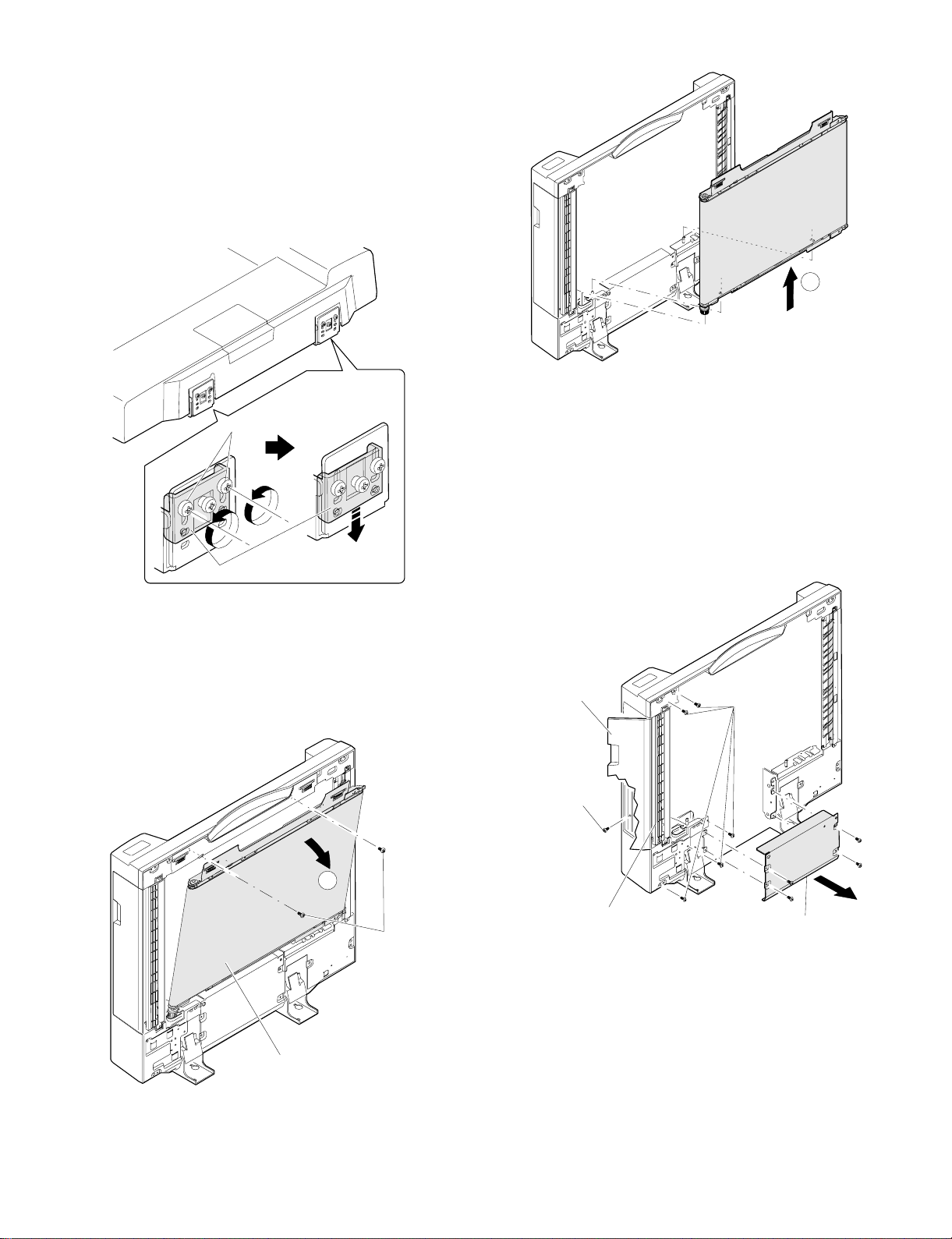
12. RADF
(1) Transport section opening
1 Loosen screws which are fixing the hinge stopper to allow the
hinge stopper to move.
2 Slide the hinge stopper downward by using the step screw, fit the
dove with the hole and tighten the fixing screws which were
loosen before.
3 Open the transport section.
B
Screw
Hinge stopper (Move down.)
(2) Belt unit disassembly
1 Open the transport section.
2 Remove screws as shown in the figure below, and remove the
belt unit as shown with arrow A and arrow B in this sequence.
(3) Paper feed unit disassembly
1 Open the transport section.
2 Remove the tray.
3 Remove screws which are fixing the lower cover, and remove the
lower cover.
4 Remove the fixing screws of the paper feed unit, open the paper
feed cover, and remove the fixing screw.
Paper feed
cover
Paper feed unit
fixing screw
Paper feed unit
fixing scr ews
Belt unit
A
Paper feed unit
Screw
7 – 16
Lower cover
Page 71

5 Remove the paper feed motor drive belt, and remove the four
g
harness connectors. Then remove the paper feed unit.
Harness
connector
(5) Separation roller disassembly
1 Open the paper feed cover.
2 Remove fixing screws of the separation unit, and remove the
separation unit.
Screw
Separation unit
Paper feed
unit
Paper feed motor
drive belt
Paper feed
motor
(4) Paper exit unit disassembly
1 Open the transport section and remove the lower cover.
2 Remove the fixing screws of the paper exit unit.
3 Remove the paper exit unit harness connector from the control
PWB, and pull out the harness from the edge saddle shown in the
figure below. Then remove the paper exit unit.
Edge saddle
Screw
Reverse
unit
3 Remove screws from the separation unit, and remove the separa-
tion roller holder unit.
Screw
Separatio n roller
holder unit
4 Remove springs from the separation roller holder, and remove the
bearing and the slide bearing. Remove the separation roller and
the spring clutch.
Screw
7 – 17
Spring
Slide shaft
bearing
Separation roller
Spring clu tch
Shaft bearin
Page 72

(6) Semi-circular roller, paper feed roller
disassembly
1 Open the paper feed cover.
2 Loosen fixing screws of the tray guide top, and remove fixing
screws of the side.
3 Remove the harness from the tray guide upper, and remove the
tray guide.
(Be car eful not to damage the harness.)
(7) Open/close switch attachment
When closing the transport section from the open state, adjust the
DF open SW plate so that the clearance between the glass surface
and the DF spacers L and R (front side) is 10 ∼ 40mm. Then tighten
the fixing screw.
Side fixing screw
Tray guide
Side fixing
screw
Harness
Top fixing screw
4 Remove the snaps from the both ends of the pickup shaft and the
separation shaft. (2 kinds of snaps)
5 Remove the pickup shaft bearing and the separation shaft bearing
on the front frame side.
6 Slide the pickup shaft toward the rear frame, and pull out the front
frame side from the chassis.
7 Remove the shaft stopper and the parallel pin from the pickup
shaft and remove the semi-circular shaft.
8 Slide the separation shaft toward the rear frame, and pull out the
front frame side from the chassis.
9 Remove the shaft stopper from the separation shaft, and remove
the paper feed roller.
10~40mm
Microswitch
Fixing
screw
DF open SW plate
(8) Document transport belt replacement
1 Remove the belt unit.
2 Remove the screws shown in the figure below to allow the belt
tension plate to be moved. Remove the transport belt with the left
and the right in parallel.
Document
transport
belt
Shaft stop
Pickup sha f t
Snap
Rear frame
side
Semi-circular roller
Parallel pin
Separation shaft
Snap
Bearing
Shaft stop
Paper feed
roller
Fron t frame
side
Screw
Belt tens io n plate
7 – 18
Page 73

[Note for assembly]
1 When installing the document transport belt, put the right and left
in parallel, and allow the same clearance between the spacer and
the belt in the front side and in the rear side.
(9) CONNECTOR LAYOUT
1 Control PWB peripheral
Spacer
Belt unit
Spacer
Spacer
Spacer
2 Check that the document transport belt is not on the belt guide.
Belt guide
Control PWB
Drive R harness
Drive I/F harness
IF harness
RU harness
Control PWB
TR1 har n ess
SNR harness
SENSOR I/F
harness
Transport belt
Belt guide
Transport belt
Control PWB
Transp o rt moto r (DTM )
LED harne ss
SENSOR I/F
harness
Drive I/F harness
7 – 19
Page 74

2 Paper feed motor peripheral
4 Reverse unit section (Front side)
Paper feed motor (DFM)
Paper feed m o tor
rotation sensor
Document
sensor (DSS)
TR2 harness
Drive F harness
SENSOR 2 harness
SENSOR ha rness
Paper feed
guide switch
(FGOD)
RU harness
Reverse solenoid (DRSOL)
5 Reverse unit section (Rear side)
Reverse guide switch
(TGD)
Reverse motor (DRM)
Control PWB
Paper fe ed mo t or
(DFM)
3 Paper feed section (Front side)
SENSOR 2
harness
Paper feed motor rotatio n
sensor (DRM RS)
RU harness
Drive R harness
6 Tray inside
Document length sensor 2 (DLS2)
(Inch seri es only)
Documentl length sensor 1 (DLS1)
Tray harness
Document end
sensor (DED)
Document width volume
sensor (DWVR)
Paper feed sole noi d (DFSOL)
SOL harness
7 – 20
Page 75

13. DESK UNIT
(1) Paper tray 2 section
A. Paper tray 2
a. Remove the stopper and pull out the paper tray 2.
(2) Paper tray 3 section (LCC tray)
A. Paper tray 3
a. Remove the desk cabinets R/L.
b. As shown in the figure, press the lever upward or downward, to
unlock the accuride and rail.
c. Remove the accuride and pull out the paper tray 3 unit.
Right st opper
Stopper
Notch
Guide rails
Guide
Rail
Cassette
side
Lever
B. Lift-up drive units L/R
a. Remove the paper tray 3.
b. Remove the front cover of the paper tray 3.
c. Remove the lift-up units L/R.
B. Paper pick-up unit
a. Pull out the paper tray 2.
b. Remove the right cabinet/front right cabinet.
c. Pull out the paper pick-up unit.
Mounting screw B
Paper fe ed unit
Guide rail
Lift-up drive un it L
Lift- up dri ve unit R
7 – 21
Page 76
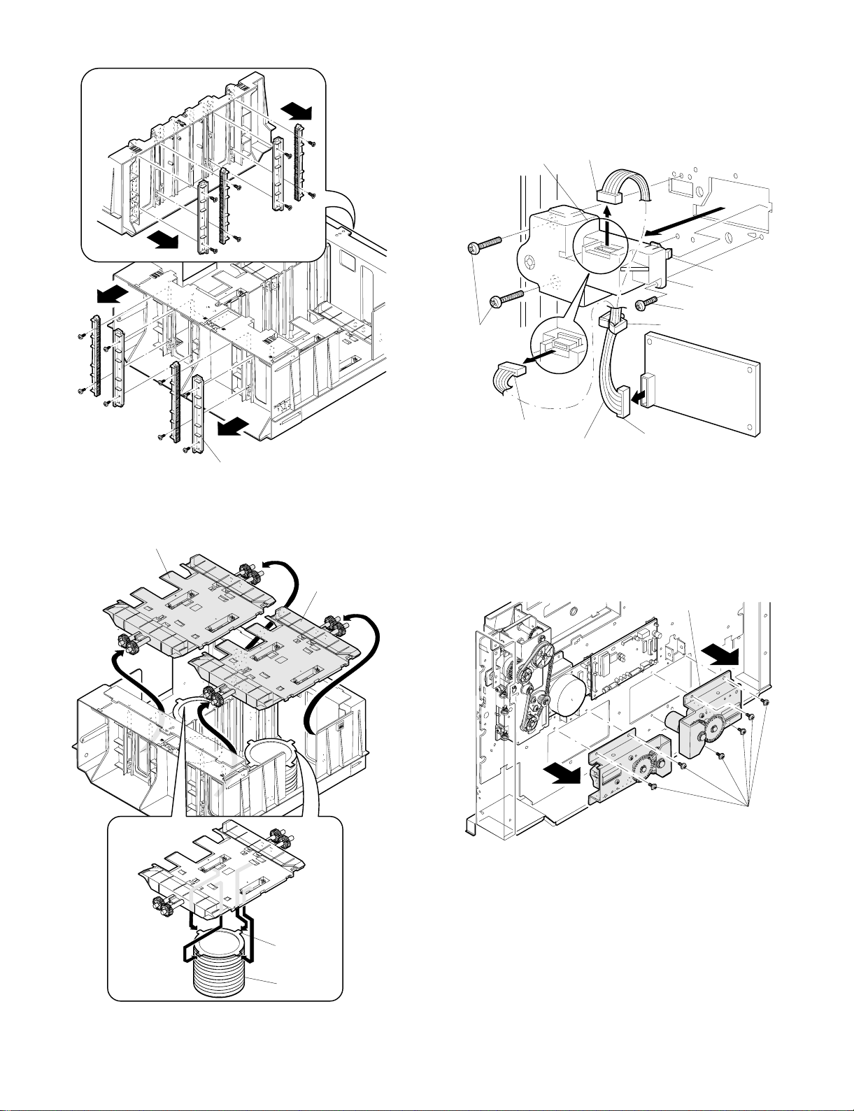
d. Remove the lifter guide rack.
(3) Desk back cabinet section
A. Paper tray 2 lift-up unit
a. Remove the desk back cabinet.
b. Pull out the connector and remove the paper tray 2 lift-up unit.
(At this time, use caution not to break the lift-up unit latch.
Lift-up gu ide rac k
C. Remove the damper latch and remove the main lifter.
Lift-up main unit R (with guide roller)
Lift-up main unit L
Type A
Mounting
screw(A)
Connector
(black)
Connector(black)
Type B
Relay
harness
Hook
Lift-up unit
Mounting screw(B)
Cord clip
Circuit board
Connector
(white)
B. Paper tray 3 lift-up unit
a. Remove the desk back cabinet.
b. Remove the harness from the wire saddle.
c. Remove the paper tray 3 lift-up unit 1 and paper tray 3 lift-up unit
2.
Drive units (2)
Latch
Damper
Note: When reinstalling the lifter guide rack, hold the main lifter
down against the lowest position. At this time, make sure the
main lifter is horizontal (in all directions).
(A) Screw
7 – 22
Page 77

C. Drive unit
a. Remove the desk back cabinet.
b. Remove the drive unit.
c. Remove the resist clutch harness.
d. Remove the paper transport motor unit.
(4) LCC paper transport section
A. LCC paper transport unit
a. Remove the desk cabinets R/L.
b. Remove the paper tray 2 and paper tray 3.
c. Remove the LCC paper transport unit.
Belt
Drive unit
Resist clutch harness
Note: When reinstalling, temporarily secure the paper transport
motor unit with screws (with the belt passed). After making
sure the belt is stretched by the paper transport motor unit’s
own weight, tighten the screw securely.
Transport
motor unit
D. Paper transport motor
a. Remove the back cabinet.
b. Remove the paper transport motor unit.
c. Remove the gear and detach the paper transport motor.
Note: When reinstalling, observe the following precautions:
• Do not leave the LCC paper transport unit halfway along the rail.
• Use caution not to get the harness caught in the parts.
B. Pick-up clutches 1, 2
a. Remove the LCC paper transport unit.
b. Remove the connector.
c. Turn the shaft so that the latch shown in the figure be positioned
for easy removal. Push up the latch with the precise slotted
screwdriver in the direction indicated by the arrow, to remove the
clutch.
Lock
Latch
Side view of clutch
Pick-up clutch 1 or 2
Latch
Note: When reinstalling, it is good practice to pass the belt through
the pulley between the drive unit and the paper transport
motor unit. This will make it easier to reinstall.
Pick-u p roller unit CEN or LEF
7 – 23
Page 78

Note:
• When removing, use caution not to break the latch. If the latch is
accidentally broken, remove all fragments of the part to prevent
any of them from getting caught in the gears and other parts.
• When reinstalling, push in the clutch until the latch settles in the
groove in the shaft.
• Make sure the snap ring of the clutch is settled in the groove in the
LCC paper transport unit.
C. Pick-up roller
a. Remove the LCC paper transport unit.
b. Hold down the pick-up roller from upside, to make it in the state as
shown in the figure.
Hold down
D. Separation roller clutch
a. Remove the LCC paper transport unit.
b. Remove the E-ring and detach the bearing.
c. Remove the connector.
d. Turn the shaft so that the latch shown in the figure be positioned
for easy removal. Push up the latch with the precise slotted
screwdriver in the direction indicated by the arrow, to remove the
clutch.
Lock
Latch
Side view of clutch
Joggl e
Screw
Latch
c. Remove the clip and detach the pick-up roller.
Clip
Shaft
Roller
Separation
clutch
Screw
E ring
Note:
Bearing
Screw
Screw
• When removing, use caution not to break the latch. When the latch
is accidentally broken, remove all fragments of the part to prevent
any of them from getting caught in the gears and other parts.
• When reinstalling, push in the clutch until the latch settles in the
groove in the shaft.
• Make sure the snap ring of the clutch is settled in the groove in the
LCC paper transport unit.
7 – 24
Page 79

E. Paper transport roller/Separation roller/Torque limiter
a. Open the desk right door.
b. Remove the one-way clutch and paper transport roller.
c. Remove the separation roller and torque limiter.
B. Resist sensor
a. Remove the resist roller unit.
b. Remove the resist roller sensor unit.
Resist sensor 1
Forward roller
(same as reverse roller)
One-way clutch
Torque limiter
Clip
Note: When reinstalling the torque limiter, align the notch with the
parallel pin on the shaft and make sure the torque limiter is
inserted to stop.
Reverse roller
(same as forward roller)
(5) Resist roller unit
A. Resist roller unit
a. Remove the desk cabinets R/L.
b. Remove the paper tray 2 and paper tray 3.
c. Remove the screws and slide the resist roller unit to the left to
remove it.
Blue lead wire
Resist s ens or unit
Harness unit
White lead wire
C. Resist roller
a. Remove the resist roller unit.
b. Remove the E-ring and detach the gear and belt.
c. Remove the clip.
d. Shift the resist roller to the left and remove it.
Resist roller
x 2 pcs.
resist roller unit
Screw
Resist sensor unit
Resist sensor 2
Screw
SP-resist PC
Frame unit
Resist unit
Screw A
Cable band
Screw B
Note: When reinstalling the resist roller unit, observe the following
precautions:
• The cable band should be tied together with the resist roller unit.
• Pay attention to the lengths of the screws A and B. (The screw A is
longer than the screw B.)
SP-resist PC
E ring 5
Resist roller
Note: When reinstalling the resist roller, install the gold color spring
at the upper side.
7 – 25
Page 80

[8] ADJUSTMENT
No. Item Contents Simulation
1 Developing
section
2 Process section (1) Adjusting high voltage output and balance A Using special measurement tools
3 Laser unit (1) Checking printing by laser unit
4 Optical section (1) Adjusting magnification in main-scanning direction
5 Document
detection section
6 Others (1) Printing off-center 50-10, 50-11
7 Paper tray 1/2 (1) Adjust any center misalignment
8 Paper tray 3 (1) Adjust any center misalignment
9 ADU (1) Adjust any matching guide 52-01
10 RADF (1) Adjust any center misalignment
(1) Adjusting developing doctor clearance
(2) Adjusting developing magnet roller main pole position
(3) Adjusting DV bias voltage 8-01
(4) Pay attention to the following points when installing
developing unit rollers
(5) Pay attention to the following points when attaching front
and rear developing side seals.
B Adjusting transfer charger current 8-06
C Adjusting main charger grid voltage 8-02
D Adjusting separation charger output 8-07
(2) Precautions in maintaining high-voltage charger unit A Main charger unit
B Transfer/separation charger unit
(adjusting distortion by self-printing mode)
(2) Adjusting magnification in sub-scanning direction 48-02
(3) Adjusting distortion in longitudinal direction
(4) Adjusting distortion in lateral direction
(5) Adjusting leading edge position of copy 50-01, 50-02
(1) Adjusting document detection arm unit 41-01
(2) Adjusting document detection level 41-02, 41-03
(2) Adjusting document off-center A Document table 50-12
(2) Adjust any center misalignment
(2) Document lead edge position adjustment 53
64-01
1. Developing section
(1) Adjusting developing doctor clearance
1 Remove the four screws securing the toner hopper and the
developer tank and 5-pin connector, to separate the toner tank
hopper from the developer tank.
2 Loosen the four screws A securing the DV doctor (2 at the front
and 2 at the rear frame).
3 Inse rt 0.05 mm clearance gauges at positions 50 ∼ 80 m m from
the end of the DV doctor.
0.03
0.55
0.03
A A
4 Press the DV doctor in the direction indicated by the arrow, and
tighten the DV doctor fixing screws (4 screws both at the front and
rear frames).
5 Make sure the clearance is 0.55+0.03-0.03 at the positions 50 ∼
80 mm from both ends of the DV doctors.
* Note: Use caution not to damage the DV doctor or MG roller
when inserting clearance gauges.
50mm
30mm
30mm
50mm
8 – 1
Page 81

(2) Adjusting developing magnet roller main pole
Keep needle
away 2 or 3 mm
P
20.5mm
A
20.5mm
position
1 Remove the four screws securing the toner hopper and the
developer tank and 5-pin connector, to separate the toner tank
hopper from the developer tank. Lay the developer tank on a level
surface.
2 Tie thread to a sewing needle or set screw, as shown above.
3 Holding one end of the thread, bring the needle close to the MG
roller keeping it horizontal. (Do not use a clip, because the MG
roller is so small that you cannot pinpoint the correct position.)
4 Keep the tip of the needle 2 ∼ 3 mm away from the MG roller
surface and mark its surface in a position which hits the line
extended from the needle’s end. (Do not let the tip of needle
contact the MG roller.)
(3) Adjusting DV bias voltage
1 Set the digital multi meter range for DC 400V or more.
2 Put the test rod between the DV bias output check pin (CP-B) and
the chassis (GND).
CPB
3 Execute SIM 8-1 to check the DV bias voltage.
DV bias in each mode Output voltage
Auto 8-1 –400 ±5V
Manual 8-1 –400 ±5V
Photo 8-1 –400 ±5V
Soft-focus photo 8-1 –400 ±5V
Toner saving 8-1 –350 ±5V
Printer 8-1 –400 ±5V
4 If the DV bias output voltage is not in the range shown in the
above table, change the set value again.
(4) Pay attention to the following points when
installing developing unit rollers
1 Direction of installing V rings
2 Make sure there is no clearance between the V ring and roller in
the marking position (@).
5 Measure the distance between the marking and the developer
tank shaded area P. Make sure the distance is 20.5 mm.
If the value is not as specified, loosen the screw A securing the
main pole adjustment plate and move the adjustment plate
properly in the direction indicated by the arrow.
V ring, φ8
V ring, φ8
(Rear) (Front)
MG roller
3 Installation of the φ8 ring, C ring 8 and φ6 V rings.
8 – 2
V ri ng φ6
(Re ar) (Front)
Roller SV (X1)
V ring φ6
Page 82

Developing magnet roller
V ri ng φ6V ring φ6
V ri ng φ6V ring φ6
(Rear) (Front)
B
A
C
D
1) Pay attention to the direction of the V rings.
2) Make sure there is no clearance at the area where the V rings
are in contact with each roller.
2. Process sect io n
(1) Adjusting high voltage output and balance
A. Using special measurement tools
Electrode sheet (UKOG-0110FCZZ)
(5) Pay attention to the following points when
attaching front and rear developing side seals
1 Clean the surface where the seals are to be attached, of lubricant
and foreign matter.
2 Make sure seals are securely attached, without peeling off.
UKOG-0110FCZZ
Electrode sheet harness (DHAI-0304FCZZ)
Orange
(Microswi tch)
(QSW-M0118FCZZ)
Orange
PHOG-0007FCZZ
QTIPH0017FCZZ
White
A
White
Red
Blue
Black
Green
Blue
Black
Yellow
Red
(QCLIZ0 005FCZZ)
(QCLIZ0006FCZZ)
(QCLIZ0010FCZZ)
(QCLIZ0004FCZZ)
(QCLIZ0 002FCZZ)
(Wiring diagram of section A)
Orange
White
300KΩ X 2
(VRN-RT2EK304F)
Blue
Black
B. Adjusting transfer charger current
Remove the developing unit, transfer/separation charger unit,
1
main charger unit and waster toner collection container.
2 Remove the process unit from the machine.
Do not hold the toner transport pipe when removing (reinstalling)
the process unit from the machine.
3 Remove the OPC drum from the process unit. Attach the
electrode sheet to the OPC drum with rubber bands and tape.
4 Install the OPC drum on the process unit. Install the process unit
on the machine.
5 Install the drum holder unit into the machine so that the electrode
sheet lead wire can be drawn out from the developer tank unit
side.
8 – 3
Page 83

Green clip
Orange
Orange
6 Clean the transfer charger wire and reinstall the transfer/separa-
tion charger unit into the machine. (Do not install the main charger
yet.)
7 Connect the electrode sheet to the digital multimeter (or an am-
meter). Turn the door switch ON by hand.
8 Check the drum current on both the front and rear frame sides.
The difference in current between the front and rear frame sides
must be less than 6.0 µA.
a. Turn the main switch ON and execute SIM 8-06. (THVG turns
on and stays on for about 30 seconds.)
b. Measure the drum current on the front and rear frame sides.
• When the microswitch is OFF: the drum current on the front
frame side is displayed.
• When the microswitch is ON: the drum current on the rear
frame side is displayed.
White
Red
White
Microswitch
Chassis
(area not painted)
Digital mu l ti m eter
(UKOGE0043FC01)
Yellow clip
Black clip
Black
Blue
2
(DCmA)
20
200
Blue clip
Red clip
(Note)
Make sure the black clip is completely grounded to the chassis of the
machine.
When UKGE0043CS01 is to be used:
Knob 1: Set to DCmA
Knob 2: Set to 2
Red clip: Connect to c
Blue clip: Connect to d
When a DC ammeter is to be used:
Red clip: Connect to the c of the DC ammeter.
Blue clip: Connect to the d of the DC ammeter.
(OFF)
N/C
N/O COM
N/C
N/O COM
c. Check that the difference in current between the front and rear
frames is less than 6.0 µA. If the difference is more than 6.0
µA, it indicates the charger unit is defective. Replace the
charger unit.
9 Adjust the THVG output current.
a. Tu rn t he ma in swit ch ON and exec ut e SIM 8- 06. (THVF turn s
on and stays on about 30 seconds.)
b. Adjust the THVG output current for +13.5 ±3 µA with the THVG
output adjustment VR201.
(ON)
VR201
C. Adjusting main charger grid voltage
This adjustment should be performed with the OPC drum installed.
The electrode sheet is not used.
1 Install the DV unit and drum holder unit on the copier. Turn the
copier ON. (The electrode sheet should not be used on the drum.)
2 Install the main charger unit on the copier. All charger units should
be installed on the copier.
3 Turn the main switch ON. Execute SIM 8-2 to check the grid
voltage setting.
Note: The value of the simulation 8-2 entered and actual output
voltage do not matched with each other.
8 – 4
Page 84

(Measurement at high-voltage PWB check point)
4 Remove the rear cabinet.
5 Connect the digital multimeter to the grid voltage output check pin
(CP-GB).
6 Set the digital multimeter for the DCV range. (Use a digital multi-
meter which allows measurement up to DC 1000V.)
7 Turn the door switch ON by hand.
8 Turn the main switch ON. Execute SIM 8-02 (select all modes
from auto mode to printer mode) to check the output voltage.
J401
D. Adjusting separation charger output
This adjustment should be performed with the electrode sheet not
used.
1 Install both the DV unit and drum holder unit on the copier. Power
the copier ON.
2 Install both the separation charger unit and the drum holder unit
on the copier. All charger units should be installed on the copier.
3 Remove the rear cabinet.
4 Connect the digital multimeter to the SHVG output check pin
J501.
J401
J501
Main charger grid voltage in each mode Output voltage
Auto 8-2 –490 ±5V
Manual 8-2 –490 ±5V
Photo 8-2 –490 ±5V
Soft-focus photo 8-2 –490 ±5V
Toner saving 8-2 –440 ±5V
Printer 8-2 –460 ±5V
9 If the output voltage is out of the specified range, adjust the output
voltage by changing the value being displayed (3 digits) (The
voltage varies 1 V for every 1 step.)
5 Set the digital multimeter for the DCV range.
6 Turn the door switch ON by hand.
7 Execute SIM 8-07. (SHVG turns on and stays on for about 30
seconds.)
8 During execution of the simulation, adjust the separation charger
output monitor voltage (bias voltage) for –400 ±10V with the
SHVG output adjustment knob VR-502.
(2) Precautions in maintaining high-voltage
charger unit
A. Main charger unit
1 Make sure the screen grid is free from twist, deformation or con-
tamination when installing it. Make sure it is securely settled in the
specified positioning groove.
8 – 5
Page 85

2 Make sure the saw blades are not deformed.
2 Make sure the charger wire is not twisted or kinked. Make sure it
is properly settled in the wire positioning groove in each holder.
mm
3~5
3 Make sure the charger case is clear of oil, contamination or
foreign matter.
4 Clean the wires with alcohol, if contaminated.
3 Make sure the screen grid or saw blade are not in contact with the
inside of the MC case (saw blade side).
4 To clean the MC saw blade, use a piece of styrofoam. Stick to the
saw blade perpendicularly to remove dirt.
B. Transfer/separation charger unit
The charger SP length is 11 ±0.5 mm.
1
mm
0.5
11
3. Laser unit
(1) Checking printing by laser unit
(adjusting distortion by self-printing mode)
1 Remove the right and left document guides and remove the table
glass.
2 Remove the dark box cover and LSU lead wire cover.
3 Open the front cabinet and remove the duct and process guide
rail.
4 Execute SIM 64-1.
C
0
READY TO COPY
SELF-PRINTING MODE 0
ALL 1by1
HEIGHT
COPY RATIO
255%
0 6
1
4
8 – 6
Page 86

Rs[
5
A copy showing a checked pattern in self-printing mode is made.
(Example)
0
1C
Direction in which paper is discharged
(Example)
Put a scale on the document so that the 50-mm marking is positioned
at the center of the document.
Copy magnification correction rate in main scanning direction
100 − 98
=
100
× 100 = 1
θ
6 Loosen the laser unit fixing screw.
If θ > 90°, move the laser unit in the direction of B so that θ is 90°.
If θ < 90°, move the laser unit in the direction of A so that θ is 90°.
A
B
A
100-mm scale
(original)
10 20 90 100 110
1mm
Copy image
2 mm (2%)
shorter than
10 20 90
100 110
original
5 Remove the right and left document guides and remove the table
glass.
6 Remove the dark box cover.
7 Draw lines on the lens CCD unit fixing plate, as shown below.
B
4. Optical section
(1) Adjusting magnification in main scanning
direction
1 Lay a scale on the document table, as shown below.
Main scanning
direction
Scale
2 Make a normal (100%) copy of A4 or letter size paper.
3 Compare the length of the scale image on the copy with the length
of the actual scale.
4 Find the copy magnification correction rate in the main scanning
direction by using the following equation.
Copy magnification correction rate in main scanning direction
the size of document – the size of copy image
=
the size of document
× 100%
A4
8 Loosen the three red screws securing the lens CCD unit fixing
plate.
A
B
8 – 7
Page 87

Screw (red) securing lens
10 20 30 40 50 60 70 80 90 50 10 0110 120130140
Scale
Sub scanning direction
CCD unit
* Under any circums t a nce,
do not loosen this screw.
Adjustment may beco m
easier by inserting front
cabinet hi ng e L angles
(bars).
* Two angles are needed.
AB
If the copy image is longer than the document, move the unit in
the direction of B.
If the copy image is shorter than the document, move the unit in
the direction of A.
(The length varies in steps of 0.2% by every 1 marking.)
Note: Under any circumstances, the red lens CCD unit
fixing screw should not be removed.
(2) Adjusting magnification in sub-scanning
direction
1 Lay a scale on the document table and execute SIM 48-02. The
machine enters the warm-up cycle and the ready lamp comes on.
At the same time, the current magnification setting is displayed
(any of 0 – 20). Make a normal (100%) copy and find the copy
magnification correction rate.
Copy magnification correction rate (MRCP)
the size of document – the size of copy image
=
the size of document
× 100 (%)
(Example 1)
Copy A Shorter
than the actual
10 20 90 100 110
size
Scale
(Original)
10 20 90 100 110
(Example 1)
Copy B Longer
thanthe actual
10
20 90 100 110
size
2 Change the displayed value by using the copy magnification cor-
rection rate obtained in step 1.
(Input value) = (preset value) + (copy magnification correction
rate %) × 10
• Example 1: 20 = 10 + 1 × 10
• Example 2: 10 = 10 + (–1 × 10)
Enter the input value and turn the print switch ON. The entered
value is stored in memory and the ready lamp goes out.
3 Release SIM 48-02.
(Note): Remember that the entry of simulating setting is up to 20.
(3) Adjusting distortion in longitudinal direction
This adjustment should be performed to correct the problem shown
below.
La
Direction in
which paper
Original
is discharged
• When the mirror base drive wire is replaced.
8 – 8
Lb
Copy
Page 88

1 Set a sheet of white A3 or W letter size paper on the document
table as shown below.
2 Make a normal (100%) copy.
3 Measure the widths of the leading and trailing edges of the copy.
(4) Adjusting distortion in lateral direction
If a copy image has a distortion in the lateral direction (or squareness
against the scanning direction) without showing any distortion in the
mirror base scanning direction, adjust the 2nd mirror base unit rail
height.
This adjustment should be performed if the phenomenon given below
appears.
Original Copy
1 Preparing adjustment document
Draw two lines correctly 10 mm away in parallel with each edge of
a sheet of A3 or W letter size white paper.
Parallel lines Parallel lines
Glass holder Align the edge of paper
with the edge of glass
A3 or W letter
size paper
holder.
If the black belt width at the leading edge (La) and the black belt
width (Lb) at the trailing edge are the same,
there is no need of adjustment. (You can ignore steps 4 ∼ 7.)
4 Loosen the screws securing the rear frame mirror base drive pul-
ley.
If La > Lb, turn the rear frame mirror base drive pulley in the
direction of A. (Do not move either of the flange or the mirror base
drive shaft.)
If La < Lb, turn the rear frame mirror base drive pulley in the
direction of B. (Do not move either of the flange or the mirror base
drive shaft.)
5 Tighten the screw securing the mirror base drive pulley.
6 Repeat steps 1 to 3.
7 If La = Lb, carry out steps 4 and 5. (If La = Lb, adjustment is
over.)
Repeat steps 1 to 6 until La = Lb.
10mm
10mm
10mm
10mm
White paper
2 Make a normal (100%) copy on a sheet of A3 or W letter size
paper.
3 Measure the following distances (La, Lb, Lc, and Ld) in the illustra-
tion below.
La
Lc
Direction in which
paper is discharged
A
Lb
Adjustment
1 Adjust by moving the mirror base B rail height up and down (in the
direction of indicated by the big arrow).
If La > Lb, move the paper exit-side mirror base B rail upward by
half the difference between La and Lb.
If La < Lb, move the paper exit-side mirror base B rail downward
by half the difference between Lb and La.
Example: If La is 12 mm and Lb is 9 mm, move the paper exit-
side mirror base B rail 1.5 mm upward.
8 – 9
Ld
Page 89

If Lc > Ld, move the paper feed-side mirror base B rail downward
by half the difference between Lc and Ld.
If Lc < Ld, move the paper feed-side mirror base B rail upward by
half the difference between Ld and Lc. (When moving the mirror
base rail, hold the mirror base rail handle.)
2 Adjust the mirror base rail properly using step 1, so that La = Lb
and Lc = Ld.
3 After adjustment, turn the mirror base drive pulley by hand to
operate both the mirror bases A and B fully, to make sure that
each mirror base does not interfere with other parts.
(Note): If the mirror base rail is moved extremely, the mirror bases
might interfere with other parts.
2
C
0 1
(Execute SIM 50.). After the machine has warmed up, the ready
lamp comes on. At the same time, the current setting of the leading edge position is displayed.
(Cassette adjustment)
CASSETTE ADJUSTMENT
RRC_A [ XX ]
RRC_B [ XX ]
DEN_B [ XX ]
0~99
Enter values 60, 0, and 20 for RRC-A, RRC-B and DEN-B.
0 5
Press keys in this order.
0
60
0
20
3 Set the magnification to 400% and make a copy.
(5) Adjusting leading edge position of copy
The leading edge position of copy can be adjusted by executing SIMs
50-01 and 50-02.
(normal 100% copy) Image loss: 0 ∼ 3 mm
(at leading and trailing edges)
Void area: 1 ∼ 3 mm
To adjust the leading edge of the copy, it is necessary to adjust the
tray (cassette) and manual feed positions.
<In the case of setting by executing SIM 50-01>
1 Lay a scale on the document table.
Scale
Enlargement key
•
(set for 400%, ready)
(A copy is made in a magnification of 400%.)
In SIM 50-01, measure the distances L1 and L2 on the copy, find
the values of RRC-A and RRC-B using the equation give below.
L2
L1
10 20 30
Leading edge of
scale image
Enlargement copy (400%)
L1: Distance from the leading edge of the scale image to the
10-mm marking (mm)
L2: Distance from the edge of the paper to the leading edge of
the scale image (mm)
Equation
RRC-A = 60 + (L1 × 10 – 320)/4
RRC-B = L2 × 10 – 20
4 Enter the values of RRC-A and RRC-B obtained by the above
equation.
Example:
L1 = 34 and L2 = 6.5
RRC-A = 60 + (34 × 10 – 320)/4 = 65
RRC-B = 6.5 × 10 – 20 = 45
8 – 10
Page 90

5 Make copies in magnifications of 400%, 100% and 50% each, and
check variations in the leading edge positions among these magnification settings. (about 1 mm)
6 Lay a scale and a sheet of A3 or W letter size white paper on the
document table, as shown below.
<In the case of setting by executing SIM 50-02.>
In SIM 50-02, the leading edge can be easily adjusted by setting the
values of L1 and L2.
1 Lay a scale on the document table.
Scale
Scale
50mm
A4
7 Make a copy in a magnification of 100%. Make sure the trailing
edge of the black background area falls on the scale image in a
position 1 to 3 mm away from its edge. If not, change the DEN-B
setting (trailing edge void).
Increasing the setting by one increases the void area about 0.1
mm; decreasing the setting by one decreases the void area about
0.1 mm.
Normal copy (100%)
Image loss
0 ~ 3 mm
Edge of black background section
Scale
2 (Execute SIM 50-02.) After the machine has warmed up, the
ready lamp comes on. At the same time, the display appears like
this. (cassette adjustment)
C
2
0
The machine gets in simulation mode 50-02,
starting warming up.
READY TO COPY
IMAGE POSITION 100
ADJUSTMENT (TRAY)
L1[0.1mm]
5
0
Copy sc a le ima g e
Trailing edge
of paper
Void area 1 ~ 3mm
8 Change the tray selection mode from cassette to manual, using
the tray selection key. Repeat steps 5 to 7. (There is no need to
adjust RRC-A. RRC-B and DEN-B need to be adjusted.)
9 Press the Clear key to release SIM 50-01.
The RRC-A setting can be adjusted in steps of 0.1 mm. Increasing
the setting increases the image loss (the document reading start point
is delayed); decreasing the setting reduces the image loss (the document reading start point is advanced).
The RRC-B setting can be adjusted in steps of 0.1 mm. Increasing
the setting reduces the void area at the leading edge of the paper;
decreasing the setting increases the void area.
COPY RATIO
400%
3 Make sure the "cassette" is selected. Set L1 to "0".
If the current setting is "manual", switch to "cassette" using the
tray selection key.
* By setting L1 to "0", the following adjustment values are auto-
matically set.
RRC-A: 60
RRC-B: 0
Trailing edge void (DEN-B): 20
4 Using the message feed key and the numeric keypad, set the
values of A and b to 0. Make copies in magnifications of 100%
and 400%.
0
C C
0 0 0
Enlargement key set for 400%, ready)
•
0
0
(A copy is made (100%)).
• Enlargement key (set for 400%, ready)
(A copy is made in a magnification of 400%.)
8 – 11
Page 91

5 Measure the distances L1 and L2 on the copied image and enter
the measured values in steps of 0.1 mm on the operation panel
display.
The screen can be switched over by using the message scroll key
(→).
L1
Edge
of
paper
10 20 30 40
Enlargement copy (400%)
L2
L1: Distance from the leading edge of the void area to the 10-mm
marking (mm)
L2: Distance from the edge of the paper to the leading edge of the
scale image (mm)
READY TO COPY
IMAGE POSITION 100
ADJUSTMENT (TRAY)
L2[0.1mm]
50
5. Document detection section
(1) Adjusting document detection arm unit
1 Adjusting OC switch On timing
(This adjustment should be performed at the manufacturer.)
Execute SIM 41-01.
• Loosen the document cover switch actuator adjustment screw
move the actuator, so that the OC switch changes from reverse
video to normal display when the height from the table glass to
the arm unit top is 32.0 ±0.5 mm with the document detection
arm unit being tilted slowly. (If the document cover switch On
timing is not proper, the document detection function might
malfunction.)
Original detection arm unit
32.0±0.5mm
Glass
Original cover switch act u ato r
COPY RATIO
400%
6 Measure the distance from the leading edge of the paper to the
leading edge of the scale image of each copy (400% and 100%),
and enter the measured values of L1 and L2 using the message
feed key and the numeric keypad. This automatically calculates
the values of RRC-A and RRC-B in SIM 50-01 and stores the
results in memory.
If the L1 = 24.5 mm, L2 = 15.0 mm
Input method
L1 = 24.5 mm ÷ 0.1 mm/step = 245
L2 = 15.0 mm ÷ 0.1 mm/step = 150
C C
1
2
5
4
5
0
7 After that, check and adjust the displacement, image loss and void
among different magnifications in the same manner as in SIM
50-01.
Actuator adjustment screw
(2) Adjusting document detection level
<AB format>
SIMULATION NO.41- 1
ORIGINAL SIZE PHOTOSENSOR CHECK
- B5 OCSW
A4
B5R
A4R
B4
A3
[PAUSE]KEY:END DISPLAY
<Inch format>
SIMULATION NO.41- 1
DOCUMENT SIZE PHOTOSENSOR CHECK
5•1/2" x 8•1/2"
11•1/2" x 8•1/2" OCSW
- 11•1/2" x 8 51/2"(R)
- 11•1/2" x 14"
11•1/2" x 17"
8 – 12
Page 92

(Entering document detection judgement level)
0 4 1
0 2
C
At this time, the ready lamp (RPL)
comes on.
The reference value which determines whether an document is
present or not is entered. In addition, the detection of the sensor is
monitored based on this value.
1
(Sensor check mode)
Execute SIM 41-01 to check photo sensor operation. (The system
automatically enters the check mode after document detection judgement level is entered.)
Photo sensor checking method
With the document cover opened and no document present, turn
2
the print switch (PSW) ON. The ready lamp goes out and then
comes on again. (The non-document sensor level is read.)
SIMULATION NO.41- 2
ORIGINAL SIZE PHOTOSENSOR SETUP
SET AN A3-SIZE COPY PAPER ON THE
ORIGINAL TABLE, AND TURN ON THE PRINT
SWITCH WITH THE ORIGINAL COVER OPENED.
[PAUSE]KEY:END DISPLAY
3 Lay a sheet of A3 or W letter size transfer paper on the document
table. With the document cover opened, turn the print switch ON.
(The document-present sensor level is read, and the judgement
level which determines whether an document is present or not is
stored in memory.)
(It is possible to check the sensor levels in SIM 41-03.)
C
0 1
0 4
1
* The layout of the photo sensors are as follows:
Receiving shaft
AB series Inch series
Paper size
1—
2B5
3 A4 Letter
4 B5R
5 A4R Letter-R
6 B4 Legal
7 A3 W-letter
(Checking light reception level and judgement level)
The light reception level and judgement level can be checked by
executing SIM 41-3.
1 Light reception level and setting level display mode
C
0 4
1
1234567
0 3
<AB format>
SIMULATION NO.41- 3
ORIGINAL SIZE PHOTOSENSOR SETUP
RCV LV SETUP
-- --- -- B5 XXX XXX
A4 XXX XXX
B5R XXX XXX
A4R XXX XXX
B4 XXX XXX
A3 XXX XXX
[PAUSE]KEY:END DISPLAY
<Inch format>
SIMULATION NO.41- 3
<Reference> Detection level setting principle
The sensor level with document and the sensor level without docu-
ment are read, and the average (central value) is stored in memory.
Sensor level witho ut
document
Sensor level
Judgement level
(Center value)
Sensor level with
document
DOCUMENT SIZE PHOTOSENSOR SETUP
RCV LV SETUP
5•1/2" x 8•1/2" XXX XXX
11•1/2" x 8•1/2" XXX XXX
-- --- -- 11•1/2" x 8•1/2"(R) XXX XXX
-- --- -- 11•1/2" x 14" XXX XXX
11•1/2" x 17" XXX XXX
• The light reception level and the setting level during the execu-
tion of the simulation are displayed on the LCD.
8 – 13
Page 93

6. Others
2 Execute SIM 50-12.
(1) Printing off-center
The printing off-center can be adjusted using manual paper feed as a
reference, in the following manner:
1 Check the setting of printing off-center in the manual paper feed
mode, by executing SIM 50-10.
2 Using manual paper feed setting as a reference, adjust the docu-
ment (OC cover) off-center. (refer to 5-(2).)
3 Execute SIMs 50-10 and 50-11, adjust the settings of the tray
(cassette) and ADU off-center according to the setting of manual
paper feed.
4 Adjust the tray and ADU off-center, referring to the setup proce-
dure.
(The tray and ADU off-center should be adjusted not by simula-
tions, but by mechanical means.)
(2) Adjusting document off-center
This adjustment should be performed in the manual paper feed
mode.
A. Document table
Lay a reference document on the document table.
1
(Prepare a reference document carrying an arrow at its center, as
shown below.)
C
The following message appears on the display.
READY TO COPY
IMAGE POSITION 20
After warming up,
ADJUSTMENT (DEN_B)
(0~99)
READY TO COPY
IMAGE POSITION 100
0 5
21
0
3 The RPL lamp comes on. Turn the print button On produces a
copy of the reference document. Changing the setting by 1 moves
the arrow 0.25 mm to respective directions.
Center
Center checking
chart
Original
1 2
• If the arrow is located above the center line as shown in 1,
increase the value displayed on the COPIES MADE section.
• If the arrow is located below the center line as shown in 2,
decrease the value displayed on the COPIES MADE section.
The value displayed can be changed by carrying out the following key
operation.
C
8 – 14
Page 94

7. Paper tray 1/2
a
b
Direction A
Direction B
a
b
(Reference figure)
a
b
Fig.1
Paper center line
Center line of the first copy image
Fig.2
Paper center line
Center line of the first copy image
(1) Adjust any center misalignment.
Make a copy, and if there is any center misalignment such as that
shown in Fig. 1 or Fig. 2, loosen the four screws (indicated by the
arrows) which secure the front cabinet panel.
NOTE:
The mounting screws a and b will be in the symmetrical positions
when they are tightened, as shown right.
8. Paper tray 3 (LCC tray)
(1) Adjust any center misalignment.
No adjustment should be needed for the unit as it is factory-set.
However, if it is off-center, adjust it according to the following procedure.
Make a copy. If it is off center as shown in fig. 1 or fig. 2, loosen the
two center adjuster mounting screws attached to the cassette and
adjust it following the prcedure below.
Center adjuster
• If misaligned as shown in Fig. 1
Move the front cabinet panel in direction A and retighten the two
mounting screws a and then the other two screws b. Make another
copy to confirm that the center is no longer misaligned.
• If misaligned as shown in Fig. 2
Move the front cabinet panel in direction B and retighten the two
mounting screws a and then the other two screws b. Make another
copy to confirm that the center is no longer misaligned.
Direction A
Direction B
Center adjuster mounting screws
[Note]
When mounting the center adjuster, make sure that the mounting
screws are positioned in the same spot in their respective slots.
When off center as shown in fig. 1
Move the center adjuster in direction A and secure it with the two
mounting screws. Make a copy to check whether it is centered
properly.
Fig. 1
Paper center line
Center line of the first copy image
8 – 15
Page 95

When off center as shown in fig. 2
C 0 /
2
5
1
0 /
CA
Set vaiue
5
0 / CA
Move the center adjuster in direction B and secure it with the two
mounting screws. Make a copy to check whether it is centered
proerly.
(Example) To set a value (15) with two digit, perform the following
opeartion:
51
CA
Fig. 2
Paper center line
Center line of the first copy image
9. ADU
(1) Adjust the matching guide.
1 Mark a duplex copy.
2 Remove the duplex unit from the copier main unit, and open the
paper guide.
3 Set the copy that has been made in step I or a sheet of the
same size on the duplex tray. Align the paper to either alignment
guide F, or R, to check the gap. Check to see if the gap between
either of the alignment guides and the paper is from 0 to 0.5 mm.
Paper guide
Changing the set value by (1) causes the matching guide width to
move 0.5mm to 0.6mm.
* Criterion for changing set value
1
Factory setting value
99
(Guide width becomes larger.) (Guide width becomes smaller.)
C. Perform the steps 1 to 3 again to check the width.
(2) Adjust the center misalignment
When copy result shows center dislocation as shown in Fig. 1 and
Fig. 2, loosen the four screws (indicated by ↓) that fix the front
cabinet.
b
Directi o n A
a
Direct i on B
Caution:
When you fix the front cabinet, the gap between a fixing screw and
the cabinet is symmetrical for the fixing screw sections a b.
(Referenc e dr aw i ng)
b
a
b
a
Matching guide R
Matching guide F
0 to 0.5mm
When the matching guide is not aligned properly, perform the following Procedure to adjust the matching guide.
A. Set the mode using the following key operation on the copier main
unit:
Then current set value is displayed.
B. To set the adjustment mode, input the set value as shown below
after the operation above:
(Example) To set a value (5) with one digit, perform the following
operation:
* In case of Fig. 1
Move the front cabinet to the direction A, tighten the fixing screws
a (2 pcs.) and b (2 pcs.) in this order, and make a copy again to
check that there is no center dislocation.
Fig.1
Paper center l i ne
Image center (i mage of fi rs t copy )
* In case of Fig. 2
Move the front cabinet to the direction B, tighten the fixing screws
a (2 pcs.) and b (2 pcs.) in this order, and make a copy again to
check that there is no center dislocation.
Fig.2
Paper center l i ne
Image center (i mage of fi rs t copy )
8 – 16
Page 96

10. RADF
Mounting s crew
Mark
AB
Center of document
Cent er of copy ( f irst c opy )
Fig.1
Fig.2
Center of copy (first copy)
Center of document
(1) Adjust any center misalignment.
Set the original on the tray and make a copy. When the copy slips out
of the center as Fig. 1 or Fig. 2, open the ADF cover, loosen the two
mounting screws and adjust the tray to correct position.
(2) Document lead edge position adjustment.
• The document lead edge position for RADF can be determined
using the SIM 53.
• For it had been factory set that the lead edge should stop on the
location 8, but it may be needed to make adjustment. It can be
adjusted within a range of 8mm (8 steps) at the stopper side and
7mm (7 steps) at the glass side. Adjustment can be done for each
mode of single sided, double sided, and light weight paper.
8
07123456
9 101112131415
★ Fig. 1
Move the tray in the direction A and secure it with the two mounting screws. Make sure that it is centered properly.
★ Fig. 2
Move the tray in the direction B and secure it with the two mounting screws. Make sure that it is centered properly.
8mm
Stopper
7mm
Glass
• Setup example
(1) If the lead edge of the document was still not to the stopper,
enter an optimum value.
Document
Stopper
Glass
(2) If the image at the lead edge of the document were to deform,
enter an optimum value to move to the glass side.
Document
Stopper
Glass
(3) If the document were to override the stopper, enter an optimum
value to move it to the glass side.
Document
Stopper
Glass
8 – 17
Page 97

[9] SIMULATION AND DIAGNOSTICS
3. Simulation sub code input screen
SIMULATION NO.XX- _
1. Start and end of sim ul ati on s
Note: The "PAUSE" key in the descriptions means the "INTER-
RUPT" key.
Simulation IN
The Simulation IN mode becomes only available from the Copy mode
screen.
In the simulation mode, printer operation is inhibited. Printer operation
is also inhibited in either of the Aging mode or the Adjustment Copy
mode. The printer selection key is disabled, too.
By operating the keys [C] – [PAUSE] – 0/g – [PAUSE], the simulation
main code input screen appears.
* If the interval between any two key operations is more than 5
seconds, the entry into the simulation mode is canceled.
(Ref.)
1 ∼ 9: Loading/ sensor checks
10 ∼ 19: Resetting troubles
20 ∼ 29: Counter/mode setting
30 ∼ 39: Sensor activation checks
40 ∼ 59: Adjustments
60 ∼ 69: Digital readout and printer
Simulation OUT
The simulation can be terminated by pressing the [CA] key.
1. X X X X X X X X X
2. X X X X X X X X X
n. X XX X X X X X X
INPUT SUB NO. AND PRESS PRINT SWITCH
1 If any trouble has occurred when the trouble code is requested,
the 7-segment readout displays the trouble code (main only).
[Note] The trouble code is canceled when the copier enters the
simulation IN mode.
2 Only the [PRINT] key LED comes on.
[Note] The [PRINT] key LED is usually OFF.
3 The sub code input area (2 digits) waits for the input of a sub
code.
[Numeric Key]: Sub code input
[Note] Codes are entered in the ring format.
[PRINT]: Sets entered data (if any).
[C]: Clears entered data (if any).
[PAUSE]: Returns to the main code input screen.
[Note] However, the main code is not cleared.
[CA]: Terminates simulation
[Others]: Cancels (ignores) entered data.
4 The simulation execution screen is displayed and the simulation is
executed.
2. Simulation main code input screen
SIMULATION NO. _
INPUT MAIN NO. AND PRESS PRINT SWITCH
1 If any trouble has occurred when the trouble code is requested,
the 7-segment readout displays the trouble code (main only).
[Note] The trouble code is canceled when the copier enters the
simulation IN mode.
[Note] The 7-segment readout becomes blank when the copier
enters the simulation IN mode.
2 Only the [PRINT] key LED comes on.
[Note] The [PRINT] key LED is usually OFF. It comes on when
the copier waits for the [PRINT] key to be turned ON in the
simulation mode.
3 The main code input area (2 digits) waits for the input of a main
code.
[Numeric Key]: Main code input
[Note] Codes are entered in the ring format.
[PRINT]: Sets entered data.
[C]: Clears entered data.
[CA]: Terminates simulation.
[Others]: Cancels (ignores) entered data.
4 If a simulation has a sub code, it should be executed on the sub
code input screen; a simulation does not have a sub code, it
should be executed on the simulation execution screen.
4. Simulation in-progress screen
SIMULATION NO.XX-XX
X X X X X X X X X
1 If any trouble has occurred when the trouble code is requested,
the 7-segment readout displays the trouble code (main only).
[Note] Any trouble code is not displayed during the execution of a
simulation.
The operation varies with different simulations, but it is roughly as
follows:
a After the execution of the simulation, the system waits for
[PAUSE].
b After the execution of the simulation, the simulation is ter-
minated.
c After the execution of the simulation, the simulation is ter-
minated and aging starts.
d A setting is entered and written in memory by pressing
[PRINT].
e Select an item with the numeric pad to execute the simulation.
After the simulation, the system waits for [PAUSE].
f Others
9 – 1
Page 98

5. Setting input activation
SIMULATION NO.XX-XX
X X X X SETTING [XXX] : XXX
(XXX~XXX)
INPUT SETUP VALUE AND PRESS PRINT SW
In the setting input screen, the effective range is indicated in ( ) and
the current setting is indicate d in [ ]. Behind the “:” is an input field
where the cursor blinks to prompt the operator to enter data.
• If there is no entry of data in the input field:
a Press [PRINT] to sound the error buzzer to prompt the
operator to enter data. (In the case where the system is set for
“Key click sound ON”.)
b Pressing the [PAUSE] key returns the screen to the preceding
screen, without setting any data.
[Note] The main code/sub code are not cleared.
7. Simulation list
• If there is the entry of data in the input field:
a If the entered d ata is valid, the c urrent setting in [ ] on th e
screen and in memory is updated by pressing the [PRINT] key.
(The current setting in [ ] is rewritte n.) After that, the screen
returns to the preceding one.
[Note] The main code/sub code are not cleared.
b Data in the input field can be cleared by pressing [CLEAR].
The entry of data is displayed, starting at the leftmost part of
the field. If data of more than the specified digits is entered or if
any invalid key is pressed, the input error buzzer sounds and
the entry of that data or the key is ignored. (In the case where
the system is set for “Key click sound ON”.)
6. Exception processing
1 If any “trouble” is received during the execution of a simulation,
the trouble code is displayed on the 7-segment display and the
system waists for [CA]. The trouble main/sub code modes on the
7-segment display can be switched over by pressing [PRINT].
[Note] Any trouble code is not displayed during the execution of a
simulation.
2 If the [PAUSE] key is pressed during the execution of a simula-
tion, the simulation is immediately suspended and the screen
returns to the preceding one.
[Note] The main code/sub code are not cleared.
3 If [CA] is pressed during the execution of a simulation, the execu-
tion of the simulation is stopped and the simulation is terminated.
Main
code
S-01 Checks optical system.
S-01 01 Checks mirror activation of optical system.
S-01 02 Displays operating status of optical system sensor.
S-02 Checks RADF aging.
S-02 01 RADF aging test.
S-02 02 Displays the operating status of the RADF sensor.
S-02 03 Checks forward rotation of paper feed motor.
S-02 04 Checks reverse rotation of paper feed motor.
S-02 05 Checks forward rotation of transport motor.
S-02 06 Checks reverse rotation of transport motor.
S-02 07 Checks rotation of paper eject and inversion motor.
S-02 08 Checks paper feed solenoid activation.
S-02 09 Check inversion selenoid activation.
S-03 Checks sorter activation.
S-03 02 Displays the operating status of sorter sensor.
S-03 03 Checks the activation of the transport motor.
S-03 04 Checks the activation of the bin shift motor. SF-S15 only
S-03 05 Checks the activation of the fan motor.
S-03 06 Checks the activation of the gate solenoid.
S-03 08 Checks the activation of the staple motor. SF-S53N only
S-03 09 Checks the activation of the paper holder solenoid. SF-S53N only
S-03 10 Checks the activation of the guide bar motor. SF-S53N only
S-04 Checks the activation of the desk.
S-04 02 Displays the operating status of the desk sensor.
S-04 03 Checks the upper tray cassette size switch.
S-04 04 Checks the lower tray (LCC) cassette size switch.
S-04 06 Checks the activation of the transport motor.
S-04 07 Checks the activation of the upper tray lift-up motor.
S-04 08 Checks the lift-up operation of the lower tray (LCC) cassette.
Sub
code
Content Remarks
Write in
memory
Adjustment
range
9 – 2
Page 99

Main
code
S-04 10 Checks the activation of the transport clutch.
S-04 11 Checks desk load (upper tray paper feed solenoid).
S-04 12 Checks desk load (upper tray paper feed clutch).
S-04 13 Checks desk load (lower tray (LCC) paper feed solenoid).
S-04 14 Checks desk load (lower tray (LCC) paper paper feed clutch).
S-05 Checks the lighting of lamps.
S-05 01 Checks operation panel display.
S-05 02 Checks lighting of heater lamp.
S-05 03 Checks lighting of copy lamp.
S-05 04 Checks lighting of discharge lamp.
S-05 06 Sets copy lamp lighting voltage. PCU 0-55
S-06 Checks the activation of copier components.
S-06 01 Copier main switch reset
S-06 02 Checks the activation of a copier component (PSPP) (Checks drum
S-07 Copy aging test.
S-07 01 Displays warm-up time and aging test with alert for paper misfeed.
S-07 02 Displays warm-up time and aging test without alert for paper
S-07 03 Copy aging test without alert for paper misfeed/fusing temperature
S-07 04 Warm-up disabled.
S-07 06 Intermittent aging.
S-07 07 Intermittent aging without alert for paper misfeed.
S-07 08 Displays warm-up time (without aging).
S-08 Checks developing bias voltage output.
S-08 01 Sets and checks developing bias voltage.
S-08 02 Sets and checks MHV (charging), GRID (Auto exposure mode). Setting is adjustable PCU 200-900
S-08 06 Checks THV (transfer).
S-08 07 Checks SHV (separation).
S-09 Checks ADU activations.
S-09 02 Displays ADU sensor status.
S-09 03 ADU trailing edge plate aging.
S-09 04 ADU alignment plate aging.
S-09 05 ADU loading (DGS).
Sub
code
separation solenoid for activation.).
misfeed.
control.
(Manual exposure mode) " " 200-900
(Photographic mode) " " 200-900
(Soft photographic mode) " " 200-900
(Toner save mode) " " 200-900
(Printer mode) " " 200-900
Content Remarks
Setting is adjustable PCU 0-700
(Auto exposure mode)
(Manual exposure mode) " " 0-700
(Photographic mode) " " 0-700
(Soft photographic mode) " " 0-700
(Toner save mode) " " 0-700
(Printer mode) " " 0-700
Write in
memory
Adjustment
range
S-10 Toner motor aging.
S-14 Clears troubles (excluding U2/PF trouble). PCU ---
S-16 Clears U2 trouble. PCU ---
S-17 Clears PF trouble. PCU ---
S-20 Clears maintenance counter. PCU --S-21 Maintenance cycle setting.
S-21 01 Sets maintenance cycle. PCU 0-5
9 – 3
Page 100

Main
code
S-22 Displays counters.
S-22 01 Displays maintenance counter.
S-22 02 Displays maintenance counter preset.
S-22 04 Displays JAM counter.
S-22 05 Displays total counter.
S-22 06 Displays developer counter.
S-22 07 Displays developer preset counter.
S-22 08 Displays RADF counter.
S-22 09 Displays tray and ADU counter.
S-22 10 Displays staple counter.
S-22 12 Displays drum adjustment counter.
S-22 13 Displays key operator code.
S-22 14 Displays ROM version.
S-22 15 Displays trouble counter.
S-22 16 Displays copy counter.
S-22 17 Displays PDA/ZR print counter.
S-22 20 Displays printer counter.
S-23 Prints counter/adjustment values. “Printing is possible
S-24 Clears special counters.
S-24 01 Clears JAM counter. PCU --S-24 02 Clears trouble counter. PCU --S-24 03 Clears tray and ADU counter. PCU --S-24 04 Clears RADF counter. PCU --S-24 05 Clears staple counter. PCU --S-24 07 Clears drum adjustment counter. PCU --S-24 08 Clears copy counter. PCU --S-24 09 Clears PDA/ZR printing counter. PCU --S-24 12 Clears printer counter.
S-25 Checks the activation of the main motor unit.
S-25 01 Checks activation of main motor drive unit.
S-25 02 Adjusts automatic developer. PCU 0-99
S-25 03 Sets toner control ignorance time during warm-up time. PCU 0-99
S-26 Setting.
S-26 01 Optional setting. PCU 0-15
S-26 02 Sets foolscap paper. PCU 1/2
S-26 03 Sets counter mode. PCU 0-3
S-26 06 Sets destination. PCU 1-9
S-26 15 Sets fusing curl correction mode. PCU 0/1
S-26 18 Sets toner save mode. PCU 1/2
S-26 26 Sets power save mode. PCU 0/1
S-26 27 Sets image density mode. PCU 1/2
S-27 Sets PPC communication parameters.
S-27 01 Sets PPC communication trouble. PCU 0/1
S-27 02 Sets PC/Modem telephone number. PC modem --S-27 03 Sets PC/Modem ID number. PC modem --S-27 04 Sets start/end of service. PC modem --S-27 05 Sets tag number. PCU --S-30 Displays the operating status of the paper/cassette sensors.
S-30 01 Displays the operating status of copier sensors.
S-30 02 Displays the operating status of paper size detection switch.
S-41 Checks document size detection sensor.
S-41 01 Checks document size detection sensor.
S-41 02 Adjusts document size detection sensor. PCU 0-255
S-41 03 Displays output value and setting of document size detection sensor.
Sub
code
Content Remarks
after warming up (print
PWB is needed.)”
Write in
memory
Adjustment
range
9 – 4
 Loading...