

SGS Thomson Microelectronics TMBYV10-60FILM Datasheet
®
TMBYV 10-60
SMALL SIGNAL SCH OTTKY DIOD E
DESCRIPTION
Metal to silicon rectifier diode in glass case featuring very low forward voltage drop and fast recovery
time, intended for low voltage switching mode
power supply, polarity protection and high frequency circuits.
August 1999 Ed: 1A
MELF
(Glass)
Symbol Parameter Value Unit
V
RRM
Repetitive Peak Reverse Voltage 60 V
I
F (AV)
Average Forward Current
T
i
= 25 °C
1A
I
FSM
Surge non Repetitive Forward Current
T
i
= 25 °C
t
p
= 10ms
20
Sinusoidal Pulse
A
T
i
= 25 °C
t
p
= 300µs
40
Rectangular Pulse
T
stg
T
j
Storage and Junction Temperature Range - 65 to + 150
- 65 to + 125
°
C
°
C
T
L
Maximum Lead Temperature for Soldering during 15s 260
°
C
ABSOLUTE MAXIMUM RA TINGS
(limiting values)
Symbol Parameter Value Unit
R
th (j - l)
Junction-leads 110
°
C/W
THERMAL RESISTANCE
1/5
2/5
Symbol Test Conditions Min. Typ. Max. Unit
I
R
*
T
j
= 25°C
V
R
= V
RRM
0.5
mA
T
j
= 100°C
10
VF*I
F
= 1A
T
j
= 25°C
0.7
V
I
F
= 3A 1
STATIC CHARACTERISTICS
ELECTRICAL CHARACTERISTICS
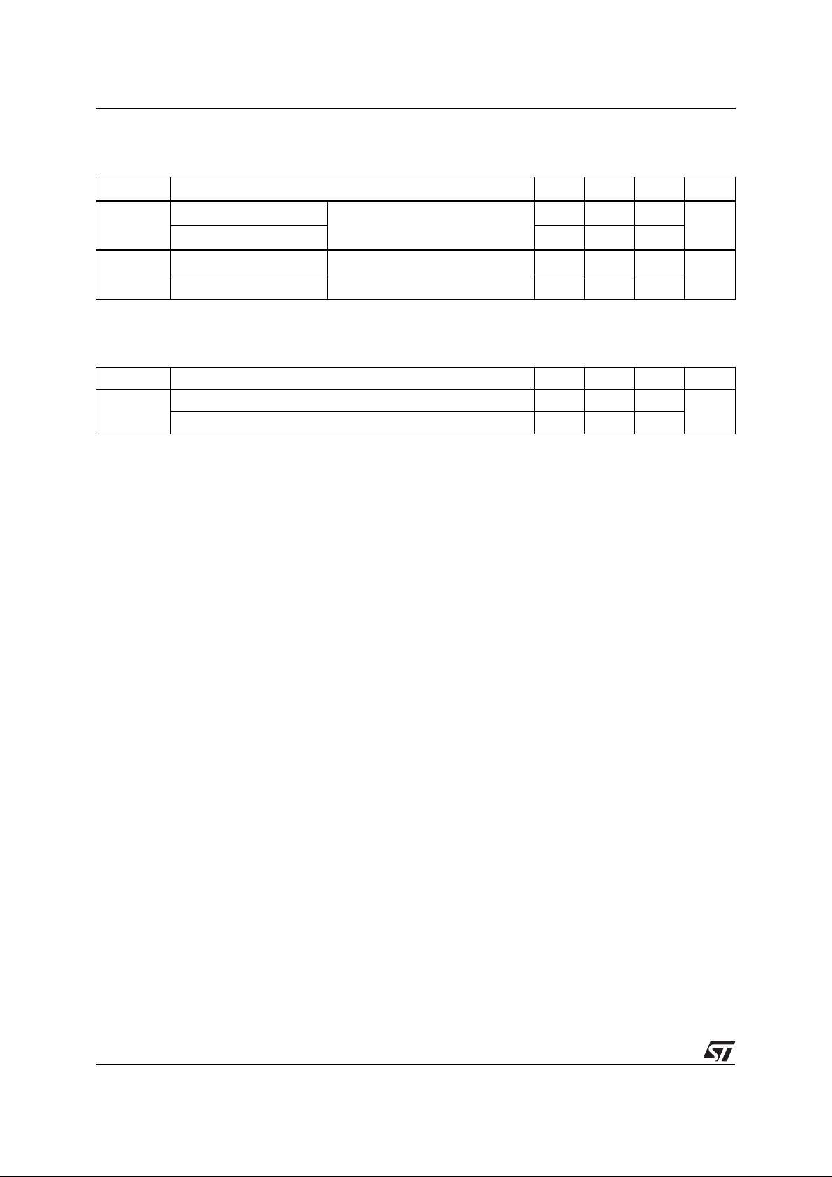
Symbol Test Conditions Min. Typ. Max. Unit
C
T
j
= 25°C VR = 0
150 pF
T
j
= 25°C VR = 5V
40
DYNAMIC CHARACTERISTICS
* Pulse test: t
p
≤
300µs δ < 2%
.
Forward current flow in a Schottky rectifier is due
to majority carrier conduction. S o r everse recovery
is not affected by s torage charge as in conventional
PN junction diodes.
Nevertheless, when the device switches from forward biased condition to reverse blocking state,
current is required to charge the depletion capacitance of the diode.
This current depends only of diode capacitance and
external circuit impedance. Satisfactory circuit behaviour analysis may be performed assuming that
Schottky rectifier consists of an ideal diode in parallel with a variable capacitance equal to the junction capacitance (see fig. 5 page 4/4).
TMBYV 10-60
 Loading...