

SGS Thomson Microelectronics TMBAT49FILM Datasheet
®
TMBAT 49
SMALL SIGNAL SC HO TTKY DIODE
DESCRIPTION
General purpose metal to silicon diode featuring
very low turn-on voltage and fast switching.
This device has integrated protection against excessive voltage such as electrostatic discharges.
August 1999 Ed 1A
MELF
(Glass)
Symbol Parameter Value Unit
V
RRM
Repetitive Peak Reverse Voltage 80 V
I
F
Forward Continuous Current
T
i
= 70 °C
500 mA
I
FRM
Repetitive Peak Forward Current
tp = 1s
δ ≤
0.5
3A
I
FSM
Surge non Repetitive Forward Current tp = 10ms 10 A
T
stg
T
j
Storage and Junction Temperature Range - 65 to + 150
- 65 to + 125
°
C
°
C
T
L
Maximum Temperature for Soldering during 15s 260
°
C
ABSOL UT E MAXIMUM RATINGS
(limiting values)
Symbol Test Conditions Value Unit
R
th(j-l)
Junction-leads 110
°
C/W
THERMAL RESISTANCE
* Pulse test: t
p
≤
300µs δ < 2%
.
Symbol Test Conditions Min. Typ. Max. Unit
I
R
*
T
j
= 25°CV
R
= 80V
200
µ
A
V
F
*
T
j
= 25°CI
F
= 10mA
0.32 V
T
j
= 25°CI
F
= 100mA
0.42
T
j
= 25°CI
F
= 1A
1
STATIC CHARACTERISTICS
ELECTRICAL CHARACT E RISTI CS
Symbol Test Conditions Min. Typ. Max. Unit
C
T
j
= 25°C f = 1MHz
V
R
= 0V 120 pF
V
R
= 5V 35
DYNAMIC CHARACTERI STICS
1/4
2/3
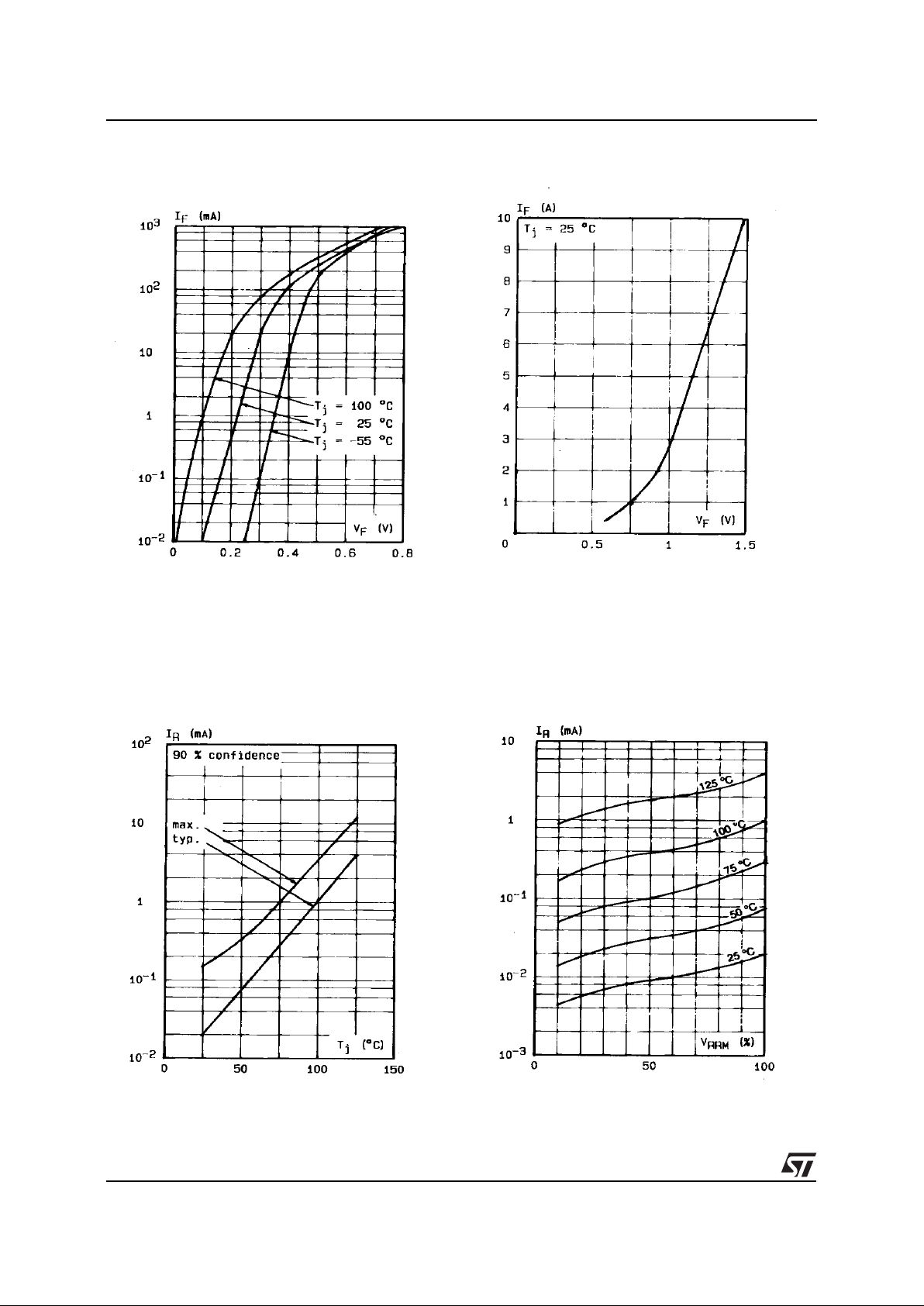
Figure 1. Forward current versus forward
voltage at low level (typical values).
Figure 2. Forward current versus forward
voltage at high level (typical values).
Figure 3. Reverse current versus junction
temperature.
Figure 4. Reverse current versus V
RRM
in per
cent.
TMBAT 49
 Loading...